JP6698046B2 - Heat conduction sheet - Google Patents
Heat conduction sheetDownload PDFInfo
- Publication number
- JP6698046B2 JP6698046B2JP2017065535AJP2017065535AJP6698046B2JP 6698046 B2JP6698046 B2JP 6698046B2JP 2017065535 AJP2017065535 AJP 2017065535AJP 2017065535 AJP2017065535 AJP 2017065535AJP 6698046 B2JP6698046 B2JP 6698046B2
- Authority
- JP
- Japan
- Prior art keywords
- heat
- sheet
- members
- distance
- diffusion sheet
- Prior art date
- Legal status (The legal status is an assumption and is not a legal conclusion. Google has not performed a legal analysis and makes no representation as to the accuracy of the status listed.)
- Active
Links
Images


Landscapes
- Cooling Or The Like Of Semiconductors Or Solid State Devices (AREA)
- Laminated Bodies (AREA)
Description
Translated fromJapanese本発明は、熱部材の間隔が変化し、又は間隔が変動しても伝熱特性が大きく変わらない熱伝導シートに関する。 The present invention relates to a heat conductive sheet whose heat transfer characteristics do not change significantly even if the distance between heat members changes or the distance changes.
電子、電気部品の中には、使用中あるいは製造中に温度が大きく変化するものがあり、様々な厚み調整が行われている。特許文献1には、静電チャック層と温度調整用ベース層との間に絶縁性有機フィルムを配置して厚み調整することが提案されている。特許文献2には、半導体レーザーモジュールに放熱板を一体化して放熱させ、半導体レーザーモジュールと回路基板との厚みを調整することが提案されている。特許文献3には、金属板の表面に突起を形成して凹凸面とし、凹部に接着樹脂を充填することが提案されている。 Some electronic and electric parts have a large temperature change during use or manufacturing, and various thickness adjustments are performed.
しかし、前記従来技術は、熱部材の間隔が変化し、又は間隔が変動したときに伝熱特性が大きく変化してしまう問題があり、さらなる改良が求められていた。 However, the above-mentioned conventional technique has a problem that the heat transfer characteristics greatly change when the distance between the heat members changes or when the distance changes, and further improvement has been demanded.
本発明は前記従来の問題を解決するため、熱部材の間隔が変化し、又は間隔が変動しても伝熱特性が大きく変わらない熱伝導シートを提供する。 In order to solve the above-mentioned conventional problems, the present invention provides a heat conductive sheet in which the heat transfer characteristics do not significantly change even if the distance between the heat members changes or the distance changes.
本発明の熱伝導シートは、熱部材間に配置する熱伝導シートであって、前記熱伝導シートは、熱拡散シートと、前記熱拡散シートを前記熱部材に面接触させて固定するための粘着材層を含み、前記熱拡散シートの粘着材層と反対の面には補強樹脂層が配置されており、前記熱部材間の間隔が変動しても、前記熱部材間の熱拡散シートの長さは一定であることを特徴とする。The heat conductive sheet of the present invention is a heat conductive sheet arranged between heat members, wherein the heat conductive sheet is an adhesive for fixing the heat diffusion sheet and the heat diffusion sheet in surface contact with the heat member.Reinforcement resin layer is disposed on the surface of the heat diffusion sheet opposite to the adhesive layer, including thematerial layer, and the length of the heat diffusion sheet between the heat members varies even if the distance between the heat members changes. Is constant.
本発明の熱伝導シートは、熱部材間に配置され、熱拡散シートと、前記熱拡散シートを前記熱部材に面接触させて固定するための粘着材層を含み、前記熱部材間の間隔が変動しても、前記熱部材間の熱拡散シートの長さは一定であることにより、熱部材の間隔が変化し、又は間隔が変動しても伝熱特性が大きく変わらない。 The heat conductive sheet of the present invention is disposed between heat members, and includes a heat diffusion sheet and an adhesive layer for fixing the heat diffusion sheet in surface contact with the heat member, and the gap between the heat members is Even if it fluctuates, since the length of the heat diffusion sheet between the heat members is constant, the distance between the heat members changes, or the heat transfer characteristics do not change significantly even if the distance changes.
本発明者は、熱部材の間隔が変化し、又は間隔が変動しても伝熱特性が大きく変わらない熱伝導シートを検討した。一般的にフーリエの法則から、厚み(L)が大きくなれば必然的に移動する熱量(Q)は小さくなる。これを図7で説明する。図7において、断面積A(m2)、の物体11の正面側が高温側(温度Th(K))であり、裏面が低温側(温度TC(K))であり、正面と裏面の距離L(m)としたとき、下記の式(数1)が成り立つ。The present inventor studied a heat conductive sheet that does not significantly change the heat transfer characteristics even if the distance between the heat members changes or the distance changes. Generally, according to Fourier's law, as the thickness (L) increases, the amount of heat (Q) that moves inevitably decreases. This will be described with reference to FIG. In FIG. 7, the front side of the

ここで、距離Lが大きくなった時に熱量Qを不変にするには、熱伝導率λ、面積Aを大きくする必要がある。しかし、実装後に面積Aを大きくすることは困難であることから、熱伝導率λを大きくすればよい。例えば、金属線などの磁性繊維状物を磁場で斜めに配向させ、高さ変化させる際、樹脂が膨張するのと併せて繊維も縦方向に膨張し、熱伝導に異方性を持たせことが考えられる。しかし、この方法では以下の問題がある。
(1)磁性繊維状物を斜めに配向させるには、技術的、量産的に難しい。
(2)実装後にシートが劣化(硬化)し、弾性が失われた場合、伸びが期待出来ない。
(3)配向具合が特性に大きく影響するため、品質保証としても難しい。Here, in order to make the heat quantity Q invariable when the distance L becomes large, it is necessary to increase the thermal conductivity λ and the area A. However, since it is difficult to increase the area A after mounting, the thermal conductivity λ may be increased. For example, when orienting a magnetic fibrous material such as a metal wire diagonally in a magnetic field and changing the height, the resin expands and the fiber also expands in the longitudinal direction, giving anisotropy in heat conduction. Is possible. However, this method has the following problems.
(1) It is technically and mass-producible to orient the magnetic fiber material obliquely.
(2) When the sheet deteriorates (cures) after mounting and loses elasticity, elongation cannot be expected.
(3) It is difficult to guarantee the quality because the orientation greatly affects the characteristics.
本発明は、以上の検討の中から着想され完成したものであり、熱部材間に配置され、熱拡散シートと、前記熱拡散シートを前記熱部材に面接触させて固定するための粘着材層を含み、前記熱部材間の間隔が変動しても、前記熱部材間の熱拡散シートの長さが一定となる熱伝導シートである。この熱伝導シートは、熱部材の間隔が変化し、又は間隔が変動しても熱部材間の熱拡散シートの長さは一定である。これにより、伝熱特性が大きく変わらない。熱部材間を圧縮したり、熱部材の振動が激しくても、この関係は変わらない。したがって、熱部材間を圧縮したり、熱部材の振動が激しい装置に好適に組み込むことができる。熱拡散シートの両主面に粘着材層を配置するのは、加熱部材と一体化するためである。 The present invention was conceived and completed from the above studies, and is arranged between heat members, and a heat diffusion sheet and an adhesive layer for fixing the heat diffusion sheet in surface contact with the heat member. And the length of the heat diffusion sheet between the heat members is constant even if the distance between the heat members changes. In this heat conductive sheet, the length of the heat diffusion sheet between the heat members is constant even if the distance between the heat members changes or the distance changes. As a result, the heat transfer characteristics do not change significantly. This relationship does not change even if the heat members are compressed or the heat members vibrate violently. Therefore, the space between the heat members can be compressed, and the heat members can be suitably incorporated into a device in which vibration is severe. The reason why the pressure-sensitive adhesive layers are arranged on both main surfaces of the heat diffusion sheet is to integrate with the heating member.
熱拡散シートの形状は、接触面間にある熱拡散シートの距離が変わらない形状であれば、いかなる形状でもよく、好ましくは断面から見て円弧又は屈曲を有する形状である。より好ましくは、長円形状又はU字状である。また、直線部分に粘着材層が一体化されているのが好ましい。直線部分に粘着材層が一体化されていると、熱伝導面積を広く取れ、熱部材間に固定できる。前記熱拡散シートの肉厚は、0.05〜1mmが好ましい。また、粘着材層の厚さは0.01〜5mmが好ましい。直径は本発明品の実装される装置の形状、サイズに合わせて任意に選択できる。 The shape of the heat diffusion sheet may be any shape as long as the distance of the heat diffusion sheet between the contact surfaces does not change, and is preferably a shape having an arc or a bend when viewed from the cross section. More preferably, it is oval or U-shaped. Further, it is preferable that the adhesive layer is integrated with the straight line portion. When the pressure-sensitive adhesive layer is integrated with the straight line portion, a large heat conduction area can be secured and the heat members can be fixed between the heat members. The thickness of the thermal diffusion sheet is preferably 0.05 to 1 mm. Moreover, the thickness of the adhesive layer is preferably 0.01 to 5 mm. The diameter can be arbitrarily selected according to the shape and size of the device on which the product of the present invention is mounted.
熱拡散シートは1本でもよいし、複数本配置してもよい。複数本並列に配置すると各熱拡散シートがつぶれる際には干渉しあい、強度は高くなる。 One heat diffusion sheet may be provided, or a plurality of heat diffusion sheets may be provided. When a plurality of heat diffusion sheets are arranged in parallel, they interfere with each other when they are crushed, and the strength is increased.
熱拡散シートは、グラファイトシート、金属箔及び熱伝導性シリコーンゴムシートから選ばれる少なくとも一つをシートとしたものが好ましい。前記金属箔は、例えばアルミニウム、銅及び金から選ばれる少なくとも一つである。これらは熱伝導率が高いからである。 The heat diffusion sheet is preferably a sheet made of at least one selected from a graphite sheet, a metal foil and a heat conductive silicone rubber sheet. The metal foil is at least one selected from aluminum, copper, and gold, for example. This is because these have high thermal conductivity.
熱拡散シートは、内層に補強樹脂層が配置されていてもよい。補強樹脂層は例えばポリイミド層であり、厚さは6〜100μmが好ましい。内層に補強樹脂層が配置されていると、熱拡散シートの補強になり、圧力をかけて長円状にしたときも潰れにくくなる。 The heat diffusion sheet may have a reinforcing resin layer as an inner layer. The reinforcing resin layer is, for example, a polyimide layer, and the thickness is preferably 6 to 100 μm. When the reinforcing resin layer is arranged as the inner layer, it serves as a reinforcement for the heat diffusion sheet, and is less likely to be crushed even when pressure is applied to form an oval shape.
前記粘着材層は、熱伝導性粘着材層であるのが好ましい。粘着材層は熱伝導性フィラーを含んでいてもよい。熱伝導性粘着材層には好ましくは熱伝導性フィラーを含ませる。これにより、全体として熱伝導性を上げることができる。 The adhesive layer is preferably a heat conductive adhesive layer. The adhesive layer may contain a heat conductive filler. The heat conductive adhesive material layer preferably contains a heat conductive filler. Thereby, the thermal conductivity can be improved as a whole.
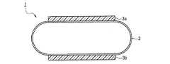
以下、図面を用いて説明する。図面中、同一符号は同一物を示す。図1は本発明の一実施態様における熱伝導シートの模式的断面図である。この熱伝導シート1は長円状の熱拡散シート2の両主面に粘着材層3a,3bが一体されている。粘着材層3a,3bは、両面テープに用いられるものであれば何でもよく、シリコーンゴム、シリコーンゲル、アクリル系粘着材層等を使用できる。この熱拡散部材は、熱部材の間隔が変化し又は間隔が変動しても、熱部材間の熱拡散シートの長さは一定である。 Hereinafter, description will be given with reference to the drawings. In the drawings, the same reference numerals indicate the same items. FIG. 1 is a schematic sectional view of a heat conductive sheet according to an embodiment of the present invention. In this heat
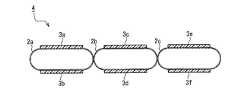
図2は本発明の別の実施態様における熱伝導シートの模式的断面図である。この熱伝導シート4は長円状の熱拡散シート2a−2cのそれぞれの両主面に粘着材層3a−3fが一体されている。この熱拡散部材も熱部材の間隔が変化し又は間隔が変動しても、熱部材間の熱拡散シートの長さは一定である。 FIG. 2 is a schematic sectional view of a heat conductive sheet according to another embodiment of the present invention. In this heat conductive sheet 4,
図3は本発明のさらに別の一実施態様における熱伝導シート5の模式的断面図であり、熱拡散シート2の内層に補強樹脂層6が一体化されている。この熱拡散部材も熱部材の間隔が変化し又は間隔が変動しても、熱部材間の熱拡散シートの長さは一定である。 FIG. 3 is a schematic cross-sectional view of the heat
図4A-Dは本発明のさらに別の一実施態様における熱伝導シートの模式的断面図である。図4Aの熱伝導シートは熱拡散シート11が外側に屈曲した例である。図4Bの熱伝導シートは熱拡散シート12が内側に屈曲した例である。図4Cの熱伝導シートは熱拡散シート13がジクザグ状に屈曲した形状の例である。図4Dの熱伝導シートは熱拡散シート14がZ字状に屈曲した形状の例である。
これらの熱拡散シートは粘着材層3a,3bにより熱部材である金属ブロック8,9に粘着一体化されて実装される。これらの熱拡散部材は、熱部材の間隔が変化し又は間隔が変動しても、熱部材間の熱拡散シートの長さは一定である。4A-D are schematic cross-sectional views of a heat conductive sheet according to still another embodiment of the present invention. The heat conduction sheet of FIG. 4A is an example in which the
These heat diffusion sheets are mounted by being adhesively integrated with the metal blocks 8 and 9 which are heat members by the
図5A-Dは本発明のさらに別の一実施態様における熱伝導シートの模式的断面図である。図5A-Cの熱拡散シート15〜17は、図4A-Cに示す熱拡散シートの左側屈曲部がないものである。図5Dは熱拡散シート18がU字形のシートの例である。これらの熱拡散シートも粘着材層3a,3bにより熱部材である金属ブロック8,9に粘着一体化されて実装される。これらの熱拡散部材は、熱部材の間隔が変化し又は間隔が変動しても、熱部材間の熱拡散シートの長さは一定である。 5A to 5D are schematic cross-sectional views of a heat conductive sheet according to still another embodiment of the present invention. The
以下実施例を用いて説明する。本発明は実施例に限定されるものではない。 An example will be described below. The invention is not limited to the examples.
<熱抵抗の測定方法>
ASTM D5470に従い、図6に示す方法により熱伝導シートの熱抵抗を測定した。図6において、金属ブロック8,9の間をスペーサーにより所定の距離Lを保持した。金属ブロック8,9の間には、シート状にした熱伝導シート1を配置した。金属ブロック8から金属ブロック9への定常状態における熱抵抗を測定した。すなわち、Coolingユニットは温度を10℃に設定されており、上部ヒーター部の温度が外気温度に対して±0.3℃になるよう電力をかけて測定した。熱抵抗値は下記式(数2)で算出する。
(数2) 熱抵抗値(Kcm2/W)=温度差ΔT(K)×製品面積(cm2)/通過する熱量(W)
得られた熱抵抗値(K・cm2/W)のKはケルビンである。金属ブロック8,9内には温度検出端挿入孔10a,10bに熱電対を入れて各金属ブロック8,9の温度を測定した。7はこの熱抵抗測定装置である。<Method of measuring thermal resistance>
According to ASTM D5470, the thermal resistance of the heat conductive sheet was measured by the method shown in FIG. In FIG. 6, a predetermined distance L was held between the metal blocks 8 and 9 by a spacer. The sheet-shaped
(Equation 2) Thermal resistance (Kcm2 /W) = Temperature difference ΔT (K) × Product area (cm2 )/Amount of heat passing (W)
K of the obtained thermal resistance value (K·cm2 /W) is Kelvin. Thermocouples were inserted into the temperature detection
(実施例1)
グラファイトシート、パナソニック社製、商品名”PGS EYG07 1810:厚さ100μm”を縦25mm,横50mm(幅)にカットし、長円状のシートにし、両主面に熱伝導性シリコーンゲル(富士高分子工業社製、商品名"30X-m"、 縦15mm,横15mm(幅)、厚さ0.3mm)を貼り付けた。このようにして図1に示す熱伝導シート1を作成した。この熱伝導シート1を図6に示す熱抵抗測定装置に入れ、室温(25℃)で定常状態における熱抵抗値を測定した。得られた熱抵抗値の結果は表1にまとめて示す。(Example 1)
Graphite sheet, manufactured by Panasonic Corporation, product name "PGS EYG07 1810: thickness 100 μm" is cut into a length of 25 mm and a width of 50 mm (width) to form an elliptical sheet, and heat conductive silicone gel (Fuji High A molecule name "30X-m", 15 mm long, 15 mm wide (width), thickness 0.3 mm) was attached to the molecule. Thus, the heat
表1から明らかなとおり、実施例1のシート状グラファイトシートは、ギャップ距離Lが2.0〜3.0mmまで変わっても、熱抵抗値の変化はなかった。このことから、実施例1のシート状グラファイトシートは、熱部材の間隔が変化し又は間隔が変動しても、熱部材間の熱拡散シートの長さは一定であり、伝熱特性が大きく変わらないことが確認できた。 As is clear from Table 1, in the sheet-shaped graphite sheet of Example 1, the thermal resistance value did not change even when the gap distance L changed from 2.0 to 3.0 mm. From this, in the sheet-shaped graphite sheet of Example 1, the length of the heat diffusion sheet between the heat members is constant even if the distance between the heat members changes or the distance changes, and the heat transfer characteristics greatly change. It was confirmed that there was no.
(実施例2)
グラファイトシートのサイズを縦25mm,横(幅)40mmとした以外は実施例1と同様に実験した。距離L:2.0mmのとき熱抵抗値は6.9K・cm2/W、距離L:2.5mmのとき熱抵抗値も6.9K・cm2/Wであり、熱部材の間隔が変化し又は間隔が変動しても、熱部材間の熱拡散シートの長さは一定であり、伝熱特性が大きく変わらないことが確認できた。なお、実施例1のシート状グラファイトシートに比べて熱抵抗値が低いのは、横(幅)のサイズが狭くなっているため、たわみ部分の距離(長さ)が短くなっており、熱拡散距離も短いためである。(Example 2)
An experiment was conducted in the same manner as in Example 1 except that the size of the graphite sheet was 25 mm in length and 40 mm in width (width). When the distance L: 2.0 mm, the thermal resistance value is 6.9 K·cm2 /W, and when the distance L: 2.5 mm, the thermal resistance value is 6.9 K·cm2 /W, and the distance between the heat members changes. It was confirmed that the length of the heat diffusion sheet between the heat members was constant and the heat transfer characteristics did not change significantly even if the distance or the spacing varied. It should be noted that the thermal resistance value is lower than that of the sheet-like graphite sheet of Example 1 because the lateral (width) size is narrow, and therefore the distance (length) of the flexure portion is short, resulting in thermal diffusion. This is because the distance is short.
(実施例3)
アルミニウム箔(厚さ50μm)を縦25mm,横50mm(幅)とした以外は実施例1と同様に実験した。距離L:2.5mmのとき熱抵抗値は8.3K・cm2/W、距離L:3.0mmのとき熱抵抗値も8.3K・cm2/Wであり、熱部材の間隔が変化し又は間隔が変動しても、熱部材間の熱拡散シートの長さは一定であり、伝熱特性が大きく変わらないことが確認できた。(Example 3)
An experiment was performed in the same manner as in Example 1 except that the aluminum foil (thickness 50 μm) was 25 mm long and 50 mm wide (width). When the distance L: 2.5 mm, the thermal resistance value is 8.3 K·cm2 /W, and when the distance L: 3.0 mm, the thermal resistance value is 8.3 K·cm2 /W, and the distance between the heat members changes. It was confirmed that the length of the heat diffusion sheet between the heat members was constant and the heat transfer characteristics did not change significantly even if the distance or the spacing varied.
(実施例4)
長円状シートの両主面の熱伝導性シリコーンゲルの代わりに両面テープ(リンテック社製、商品名”SI308NC”)、厚さ0.03mm、縦15mm,横15mm(幅)貼り付けた以外は実施例1と同様に実験した。距離L:2.0mmのとき熱抵抗値は5.7K・cm2/W、距離L:2.5mmのとき熱抵抗値も5.7K・cm2/Wであり、熱部材の間隔が変化し又は間隔が変動しても、熱部材間の熱拡散シートの長さは一定であり、伝熱特性が大きく変わらないことが確認できた。なお、粘着層の熱伝導率、厚さ、粘着強度による接触熱抵抗が製品の熱抵抗に影響することがわかった。(Example 4)
Double-sided tape (made by Lintec Co., Ltd., trade name "SI308NC"), thickness 0.03 mm,
(実施例5)
実施例1のグラファイトシートを使用し、図3の長円に変えて、図5Dに示すU字形のシートを作成し、両主面(直線部分)には両面テープ(リンテック社製、商品名”SI308NC”)、厚さ0.03mm、縦15mm,横15mm(幅)貼り付けた以外は実施例1と同様に実験した。距離L:2.5mmのとき熱抵抗値は15.7K・cm2/W、距離L:3.0mmのとき熱抵抗値は15.8K・cm2/Wであり、熱部材の間隔が変化し又は間隔が変動しても、熱部材間の熱拡散シートの長さは一定であり、伝熱特性が大きく変わらないことが確認できた。(Example 5)
Using the graphite sheet of Example 1 and replacing it with the ellipse of FIG. 3, a U-shaped sheet shown in FIG. 5D was prepared, and double-sided tape (made by Lintec Co., Ltd., product name) on both main surfaces (straight parts) SI308NC″), thickness 0.03 mm,
1,4,5 熱伝導シート
2,2a−2c,11−18 熱拡散シート
3a−3f 粘着材層
6 補強樹脂層
7 熱抵抗測定装置
8,9 熱部材(金属ブロック)
10a,10b 温度検出端挿入孔1, 4, 5
10a, 10b Temperature detection end insertion hole
Claims (7)
Translated fromJapanese前記熱伝導シートは、熱拡散シートと、前記熱拡散シートを前記熱部材に面接触させて固定するための粘着材層を含み、
前記熱拡散シートの粘着材層と反対の面には補強樹脂層が配置されており、
前記熱部材間の間隔が変動しても、前記熱部材間の熱拡散シートの長さは一定であることを特徴とする熱伝導シート。A heat conductive sheet arranged between heat members,
The heat conductive sheet includes a heat diffusion sheet, and an adhesive layer for fixing the heat diffusion sheet in surface contact with the heat member,
A reinforcing resin layer is arranged on the surface opposite to the adhesive layer of the heat diffusion sheet,
The heat conduction sheet, wherein the length of the heat diffusion sheet between the heat members is constant even if the distance between the heat members changes.
Priority Applications (1)
| Application Number | Priority Date | Filing Date | Title |
|---|---|---|---|
| JP2017065535AJP6698046B2 (en) | 2017-03-29 | 2017-03-29 | Heat conduction sheet |
Applications Claiming Priority (1)
| Application Number | Priority Date | Filing Date | Title |
|---|---|---|---|
| JP2017065535AJP6698046B2 (en) | 2017-03-29 | 2017-03-29 | Heat conduction sheet |
Publications (2)
| Publication Number | Publication Date |
|---|---|
| JP2018170357A JP2018170357A (en) | 2018-11-01 |
| JP6698046B2true JP6698046B2 (en) | 2020-05-27 |
Family
ID=64018942
Family Applications (1)
| Application Number | Title | Priority Date | Filing Date |
|---|---|---|---|
| JP2017065535AActiveJP6698046B2 (en) | 2017-03-29 | 2017-03-29 | Heat conduction sheet |
Country Status (1)
| Country | Link |
|---|---|
| JP (1) | JP6698046B2 (en) |
Families Citing this family (2)
| Publication number | Priority date | Publication date | Assignee | Title |
|---|---|---|---|---|
| JP2022033582A (en)* | 2020-08-17 | 2022-03-02 | 信越ポリマー株式会社 | Heat transfer members, electronic devices and batteries |
| WO2023073843A1 (en)* | 2021-10-27 | 2023-05-04 | ファナック株式会社 | Substrate fixing structure, machine, and robot |
Family Cites Families (4)
| Publication number | Priority date | Publication date | Assignee | Title |
|---|---|---|---|---|
| JPH04350958A (en)* | 1991-05-28 | 1992-12-04 | Matsushita Electric Ind Co Ltd | Heat dissipator of semiconductor integrated circuit |
| JPH1098289A (en)* | 1996-09-19 | 1998-04-14 | Sony Corp | Radiation structure of electronic component |
| JP5082970B2 (en)* | 2008-03-25 | 2012-11-28 | 富士通株式会社 | Circuit board equipment |
| JP5850160B2 (en)* | 2012-07-30 | 2016-02-03 | 株式会社村田製作所 | Electronics |
- 2017
- 2017-03-29JPJP2017065535Apatent/JP6698046B2/enactiveActive
Also Published As
| Publication number | Publication date |
|---|---|
| JP2018170357A (en) | 2018-11-01 |
Similar Documents
| Publication | Publication Date | Title |
|---|---|---|
| US9222735B2 (en) | Compliant multilayered thermally-conductive interface assemblies | |
| TWI489597B (en) | Compliant multilayered thermally-conductive interface assemblies and memory modules including the same | |
| US20100321897A1 (en) | Compliant multilayered thermally-conductive interface assemblies | |
| JP6846879B2 (en) | How to make a heat sink | |
| JP2003188323A (en) | Graphite sheet and its manufacturing method | |
| JP6698046B2 (en) | Heat conduction sheet | |
| TW201530081A (en) | Device and system for heat dissipation and manufacturing method thereof | |
| US10745561B2 (en) | Filler for heat transfer member and heat transfer member | |
| JP2009099753A (en) | heatsink | |
| JP2016066639A (en) | Heat sink having fins connected in different methods | |
| CN103493196A (en) | Heat sink with laminated fins and method for producing the same | |
| JP6446489B2 (en) | Heat spreader | |
| CN109427710A (en) | The manufacturing method of cooling fin and cooling fin | |
| JP5018195B2 (en) | Heat dissipation device | |
| JP2005159318A (en) | Heat conductor | |
| KR20150143578A (en) | Printed wiring board, manufacturing method for same, and thermally conductive body | |
| JP2014192401A (en) | Heat sink | |
| KR20140089725A (en) | Thermal diffusion sheet and the manufacturing method thereof | |
| US11268772B2 (en) | Heat transfer device | |
| CN103906411A (en) | Heat dissipation device and pressing member | |
| CN102802379A (en) | Radiation component and electronic equipment | |
| US20200296801A1 (en) | Material-removing heater device | |
| JP7442043B2 (en) | Thermal conductive sheets and electronic devices using them | |
| JP6634895B2 (en) | Electric heater | |
| KR20140075255A (en) | Thermal diffusion sheet and the manufacturing method thereof |
Legal Events
| Date | Code | Title | Description |
|---|---|---|---|
| A621 | Written request for application examination | Free format text:JAPANESE INTERMEDIATE CODE: A621 Effective date:20190314 | |
| A977 | Report on retrieval | Free format text:JAPANESE INTERMEDIATE CODE: A971007 Effective date:20191218 | |
| A131 | Notification of reasons for refusal | Free format text:JAPANESE INTERMEDIATE CODE: A131 Effective date:20200107 | |
| A521 | Request for written amendment filed | Free format text:JAPANESE INTERMEDIATE CODE: A523 Effective date:20200115 | |
| TRDD | Decision of grant or rejection written | ||
| A01 | Written decision to grant a patent or to grant a registration (utility model) | Free format text:JAPANESE INTERMEDIATE CODE: A01 Effective date:20200421 | |
| A61 | First payment of annual fees (during grant procedure) | Free format text:JAPANESE INTERMEDIATE CODE: A61 Effective date:20200427 | |
| R150 | Certificate of patent or registration of utility model | Ref document number:6698046 Country of ref document:JP Free format text:JAPANESE INTERMEDIATE CODE: R150 | |
| S531 | Written request for registration of change of domicile | Free format text:JAPANESE INTERMEDIATE CODE: R313531 | |
| R350 | Written notification of registration of transfer | Free format text:JAPANESE INTERMEDIATE CODE: R350 | |
| R250 | Receipt of annual fees | Free format text:JAPANESE INTERMEDIATE CODE: R250 | |
| R250 | Receipt of annual fees | Free format text:JAPANESE INTERMEDIATE CODE: R250 | |
| R250 | Receipt of annual fees | Free format text:JAPANESE INTERMEDIATE CODE: R250 |