JP6696580B2 - Control plane and user plane selection for data transmission - Google Patents
Control plane and user plane selection for data transmissionDownload PDFInfo
- Publication number
- JP6696580B2 JP6696580B2JP2018543258AJP2018543258AJP6696580B2JP 6696580 B2JP6696580 B2JP 6696580B2JP 2018543258 AJP2018543258 AJP 2018543258AJP 2018543258 AJP2018543258 AJP 2018543258AJP 6696580 B2JP6696580 B2JP 6696580B2
- Authority
- JP
- Japan
- Prior art keywords
- data
- context setup
- request message
- network node
- user plane
- Prior art date
- Legal status (The legal status is an assumption and is not a legal conclusion. Google has not performed a legal analysis and makes no representation as to the accuracy of the status listed.)
- Active
Links
- 230000005540biological transmissionEffects0.000titleclaimsdescription47
- 238000000034methodMethods0.000claimsdescription55
- 238000004891communicationMethods0.000claimsdescription37
- 238000005457optimizationMethods0.000claimsdescription29
- 230000001413cellular effectEffects0.000claimsdescription8
- 238000012986modificationMethods0.000claims1
- 230000004048modificationEffects0.000claims1
- 230000011664signalingEffects0.000description20
- 238000012546transferMethods0.000description15
- 238000012545processingMethods0.000description9
- 230000008859changeEffects0.000description7
- 238000010586diagramMethods0.000description6
- 238000012508change requestMethods0.000description5
- 230000006870functionEffects0.000description4
- 230000008569processEffects0.000description4
- 230000008901benefitEffects0.000description3
- 238000013500data storageMethods0.000description3
- 238000011157data evaluationMethods0.000description2
- 238000001514detection methodMethods0.000description2
- 238000007689inspectionMethods0.000description2
- 230000004044responseEffects0.000description2
- 239000000725suspensionSubstances0.000description2
- 101001055444Homo sapiens Mediator of RNA polymerase II transcription subunit 20Proteins0.000description1
- 102100026165Mediator of RNA polymerase II transcription subunit 20Human genes0.000description1
- 108091005487SCARB1Proteins0.000description1
- 102100037118Scavenger receptor class B member 1Human genes0.000description1
- 230000009471actionEffects0.000description1
- 230000004913activationEffects0.000description1
- 238000013459approachMethods0.000description1
- 230000006399behaviorEffects0.000description1
- 238000005516engineering processMethods0.000description1
- 230000000977initiatory effectEffects0.000description1
- 238000007726management methodMethods0.000description1
- 230000007246mechanismEffects0.000description1
- 230000035755proliferationEffects0.000description1
- 230000007704transitionEffects0.000description1
Images


Classifications
- H—ELECTRICITY
- H04—ELECTRIC COMMUNICATION TECHNIQUE
- H04W—WIRELESS COMMUNICATION NETWORKS
- H04W76/00—Connection management
- H04W76/10—Connection setup
- H04W76/12—Setup of transport tunnels
- H—ELECTRICITY
- H04—ELECTRIC COMMUNICATION TECHNIQUE
- H04L—TRANSMISSION OF DIGITAL INFORMATION, e.g. TELEGRAPHIC COMMUNICATION
- H04L67/00—Network arrangements or protocols for supporting network services or applications
- H04L67/01—Protocols
- H04L67/12—Protocols specially adapted for proprietary or special-purpose networking environments, e.g. medical networks, sensor networks, networks in vehicles or remote metering networks
- H—ELECTRICITY
- H04—ELECTRIC COMMUNICATION TECHNIQUE
- H04W—WIRELESS COMMUNICATION NETWORKS
- H04W24/00—Supervisory, monitoring or testing arrangements
- H04W24/08—Testing, supervising or monitoring using real traffic
- H—ELECTRICITY
- H04—ELECTRIC COMMUNICATION TECHNIQUE
- H04W—WIRELESS COMMUNICATION NETWORKS
- H04W4/00—Services specially adapted for wireless communication networks; Facilities therefor
- H04W4/70—Services for machine-to-machine communication [M2M] or machine type communication [MTC]
- H—ELECTRICITY
- H04—ELECTRIC COMMUNICATION TECHNIQUE
- H04W—WIRELESS COMMUNICATION NETWORKS
- H04W88/00—Devices specially adapted for wireless communication networks, e.g. terminals, base stations or access point devices
- H04W88/02—Terminal devices
- H—ELECTRICITY
- H04—ELECTRIC COMMUNICATION TECHNIQUE
- H04W—WIRELESS COMMUNICATION NETWORKS
- H04W88/00—Devices specially adapted for wireless communication networks, e.g. terminals, base stations or access point devices
- H04W88/16—Gateway arrangements
Landscapes
- Engineering & Computer Science (AREA)
- Computer Networks & Wireless Communication (AREA)
- Signal Processing (AREA)
- Health & Medical Sciences (AREA)
- Computing Systems (AREA)
- General Health & Medical Sciences (AREA)
- Medical Informatics (AREA)
- Mobile Radio Communication Systems (AREA)
Description
Translated fromJapanese本発明は、制御プレーンデータ伝送およびユーザプレーンデータ伝送の(再)選択の方法に関する。 The present invention relates to a method for (re) selection of control plane data transmissions and user plane data transmissions.
下記の略語および用語(違ったように述べられるとき)は、本発明において使用される。 The following abbreviations and terms (when stated differently) are used in the present invention.

以下の用語は、本発明において使用される。 The following terms are used in the present invention.
用語「サービングノード」、「MME/SGSN」、「MSC/SGSN/MME」、またはC−SGN(CIoTサービングゲートウェイノード)は、一般に、本発明の様々な実施形態を通じて使用され、コアネットワークと端末との間の制御プレーンシグナリング(NASシグナリングとして知られる)の終端であるモバイルネットワークにおいて、MSCなどの機能エンティティ、SGSNまたはMME、あるいはC−SGNその他の可能な制御プレーン機能エンティティを表す。サービングノード(MME/SGSN)は、モビリティおよびセッション管理を担う次世代ネットワークでの機能エンティティでもあり得る。 The terms “serving node”, “MME / SGSN”, “MSC / SGSN / MME”, or C-SGN (CIoT Serving Gateway Node) are commonly used throughout the various embodiments of the present invention to identify core networks and terminals. In the mobile network which is the end of the control plane signaling (known as NAS signaling) between the functional entities such as MSC, SGSN or MME, or C-SGN or other possible control plane functional entities. The Serving Node (MME / SGSN) may also be a functional entity in next generation networks responsible for mobility and session management.
用語「HSS/HLR」は、UEの加入者データが格納されるリポジトリを意味し、HSS、HLR、またはコンバインド(combined)エンティティのいずれかであり得る。 The term "HSS / HLR" means a repository in which UE subscriber data is stored and can be either an HSS, an HLR or a combined entity.
用語「端末」、「デバイス」、あるいは「ユーザ端末」または「UE」(ユーザ機器)または「MT」(移動体端末)は、これらの用語のすべてがネットワーク、モバイルネットワーク、または無線アクセスネットワークとデータおよびシグナリングを送受信するために使用される機器を同様に表すような相互交換可能な方法で使用される。 The terms "terminal", "device", or "user terminal" or "UE" (user equipment) or "MT" (mobile terminal) mean that all of these terms are network, mobile network, or radio access network and data. And used in an interchangeable manner to similarly represent the equipment used to send and receive signaling.
近年、モノのインターネット(IoT)技術およびマシンツーマシン(M2M)技術の普及により、第3世代パートナーシッププロジェクト(3GPP)のような標準化団体は、リリース10から、マシンタイプ通信(MTC)として知られる改善に取り組み始めた。エンドデバイスの価格や、そのようなデバイスを提供するための事業者のネットワークにおける価格をより一層下げるために、3GPPはセルラIoT(CIoT)と呼ばれる研究を行った。この研究では、超低複雑度で、電力が制約され、低データ転送速度であるIoTデバイスをサポートするための、アーキテクチャ拡張が検討され評価された。この研究を文書化したものは、3GPP TR23.720という文書に取り込まれている。結論は、1)必須の制御プレーン(CP)解決策(TRのセクション2に記載)を指定し、2)ユーザプレーン(UP)解決策(TRのセクション18に記載)を任意で指定することである。したがって、CP解決策は「ソリューション2」とも呼ばれ、UP解決策は「ソリューション18」とも呼ばれる。 With the recent proliferation of Internet of Things (IoT) and Machine-to-Machine (M2M) technologies, standardization bodies such as the 3rd Generation Partnership Project (3GPP) have improved from Release 10 known as Machine Type Communication (MTC). Started to work on. In order to further reduce the price of end devices and the price in the operator's network for providing such devices, 3GPP has conducted a study called Cellular IoT (CIoT). This study examined and evaluated architectural extensions to support IoT devices with very low complexity, power constraints, and low data rates. A documented version of this work is included in the 3GPP TR23.720 document. The conclusion is that 1) specify the mandatory control plane (CP) solution (described in
CIoT向けに最適化されたEPSは、通常のUEとは異なるトラフィックパターンをサポートし、既存のEPSと比べると一部のかつ必要な機能だけをサポートするだろう。単一の論理エンティティC−SGN(CIoT Serving Gateway Node)に機能の一部を実装することにより、CIoT向けに最適化されたEPSを有効にすることができる。モビリティ手順およびアタッチ手順は、対応するエンティティMME、S−GW、およびP−GW用の他の節に記載されるように実行される。単一ノード非ローミングCIoTアーキテクチャの例を図1に示す。レファレンスポイント(インタフェース)の詳細な説明は、仕様3GPP TS23.401および3GPP TS23.682にある。 EPS optimized for CIoT will support different traffic patterns than regular UEs and will only support some and necessary features compared to existing EPS. By implementing a part of the functions in a single logical entity C-SGN (CioT Serving Gateway Node), it is possible to enable EPS optimized for CIoT. The mobility and attach procedures are performed as described in other sections for the corresponding entities MME, S-GW and P-GW. An example of a single node non-roaming CIoT architecture is shown in FIG. A detailed description of the reference points (interfaces) can be found in the specifications 3GPP TS 23.401 and 3GPP TS 23.682.
CP解決策かUP解決策かの選択は、アタッチ手順中またはTAU手順中に行われる。UEは、下記を含む「優先ネットワーク動作」を指示する。
制御プレーンCIoT EPS最適化がサポートされているか
ユーザプレーンCIoT EPS最適化がサポートされているか
制御プレーンCIoT EPS最適化が望ましいか、それともユーザプレーンCIoT EPS最適化が望ましいか
S1−Uデータ転送がサポートされているか
コンバインドアタッチ(Combined Attach)無しのSMS転送が要求されているか
PDN接続無しのアタッチがサポートされているか
サービングノードは、アタッチまたはTAU受諾メッセージにて「サポートされたネットワーク動作」情報を送信する。The choice of CP or UP solution is made during the attach procedure or the TAU procedure. The UE directs "priority network operations" including:
Control plane CIOT EPS optimization is supported? User plane CioT EPS optimization is supported? Control plane CIoT EPS optimization is desired or user plane CIOT EPS optimization is desired S1-U data transfer is supported Yes? Is SMS transfer without Combined Attach required? Is support without PDN connection supported? The serving node sends the "supported network operation" information in the Attach or TAU Accept message.
CIoT EPS最適化において、UEは「PDN接続無しの受諾」をサポートすることができる。このことは、PDN接続が無いためにEPSベアラがアタッチ手順中に確立されないことを意味する。UEは、NAS (E)SMシグナリングを使用して、後の時点でPDN接続(IPまたは非IP)を要求することができる。 In the CIoT EPS optimization, the UE can support "accept without PDN connection". This means that the EPS bearer will not be established during the attach procedure because there is no PDN connection. The UE may request the PDN connection (IP or non-IP) at a later time using NAS (E) SM signaling.
サービングノードが、CP CIoT EPS最適化を使えるよう構成している場合、データは、UEとサービングノードとの間において、それらが関係するPDN接続のEPSベアラアイデンティティを含むNAS PDUで転送される。IPデータタイプと非IPデータタイプの両方がサポートされる。これは、RRCプロトコルおよびS1−APプロトコルのNASトランスポート機能、ならびに、MMEとS−GW間およびS−GWとP−GW間のGTP−uトンネルのデータ転送を使用することによって達成される。非IP接続がSCEFとともにMMEを介して提供される場合、データ転送はTS23.682に示されるように行われる。 If the serving node is configured to use CP CIoT Optimized, the data is transferred between the UE and the serving node in a NAS PDU containing the EPS bearer identities of the PDN connections with which they are involved. Both IP and non-IP data types are supported. This is achieved by using the NAS transport functions of RRC and S1-AP protocols and the data transfer of GTP-u tunnel between MME and S-GW and between S-GW and P-GW. If the non-IP connection is provided via MME with SCEF, the data transfer is done as shown in TS23.682.
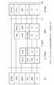
図2は、制御プレーンCIoT EPS最適化(すなわち、CP解決策)のためのモバイル発信(MO)データ伝送のシグナリングフローを示す。この図は、TS23.401に従う。ユーザデータ転送にCP解決策を使用する場合、MME(上り(UL)用)およびUE(下り(DL)用)は、NAS PDU内に含まれるEPSベアラアイデンティティ(EBI)を使用して、関連するEPSベアラを識別する。 FIG. 2 shows the signaling flow of mobile originated (MO) data transmission for control plane CIoT EPS optimization (ie CP solution). This figure complies with TS 23.401. When using the CP solution for user data transfer, the MME (for uplink (UL)) and UE (for downlink (DL)) are associated using the EPS bearer identity (EBI) contained in the NAS PDU. Identify the EPS bearer.
MMEがモバイル着信(MT)サービスにCP解決策を使用することを望む場合、TS23.401からの図3に手順例が示される。 If the MME wants to use the CP solution for mobile terminated (MT) services, an example procedure is shown in Figure 3 from TS23.401.
UEとS/PGWとの間の通信に関わる異なるプロトコルを表現するために、様々なインタフェースを介したプロトコルスタックを図4に示す。この図がCP CIoT最適化のためのプロトコルスタックを示すことに留意されたい。CIoT EPS最適化によって導入される1つの主な変更は、S11インタフェースを介した、すなわちMMEとSGWとの間のGTP−Uインタフェースのサポートである。 The protocol stacks through the various interfaces are shown in FIG. 4 in order to represent the different protocols involved in the communication between the UE and the S / PGW. Note that this figure shows the protocol stack for CP CIoT optimization. One major change introduced by the CIoT EPS optimization is the support of the GTP-U interface via the S11 interface, ie between MME and SGW.
必須として同意されたCPデータ伝送に加えて、UPデータ伝送を使用することも任意選択で可能である。ここで、主な特徴は、UEのASコンテキストをeNBに格納するためのRRC中止手順にある。この手順を図5に示す。これはTS23.401セクション5.3.4Aのとおりである。さらに、TS23.401セクション5.3.5Aでは、接続再開手順が説明されている。 In addition to the CP data transmission, which has been agreed as mandatory, it is optionally possible to use UP data transmission. Here, the main feature lies in the RRC termination procedure for storing the AS context of the UE in the eNB. This procedure is shown in FIG. This is as per TS 23.401 section 5.3.4A. Furthermore, TS 23.401 section 5.3.5A describes the connection resumption procedure.
CIoT EPS最適化は、LTE(EUTRAN)システムにも適用できる。特に、1つの目的は、低コスト特性を有する広帯域(WB)EUTRAN UE(例えば、cat−M)をカバーすることである。しかし、NB−IoTの可能なWB EUTRAN UEがNB−IoT解決策(CPまたはUP解決策)を使用する場合、RATを変更する際にいくつかの制約がある。例えば、UEが非IP接続をアクティベートした場合、UEは2G/3Gアクセスを再選択せず、非IP接続の使用を続ける。 The CIoT EPS optimization can also be applied to the LTE (EUTRAN) system. In particular, one purpose is to cover wideband (WB) EUTRAN UEs (eg cat-M) which have low cost characteristics. However, if a NB-IoT capable WB EUTRAN UE uses the NB-IoT solution (CP or UP solution), there are some restrictions in changing the RAT. For example, if the UE activates a non-IP connection, the UE does not reselect 2G / 3G access and continues to use the non-IP connection.
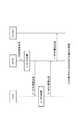
SCEFによる非IPデータ配信(NIDD)は、現在3GPP Tdoc S2−160832(TS23.682にて実現される必要がある)が手順を示しているが、3GPP TS23.682に保存されるだろう。NIDDは、UEとのモバイル発信(MO)およびモバイル着信(MT)の通信を処理するために使用され、通信に使用されるパケットはインターネットプロトコル(IP)に基づかない。非IPデータの配信のためのSCEFの構成は、図6の説明に示されており、詳細な説明は、3GPPTdoc S2−160832にある。 Non-IP Data Delivery (NIDD) via SCEF will be preserved in 3GPP TS23.682, although currently 3GPP Tdoc S2-160832 (needs to be implemented in TS23.682) shows the procedure. NIDD is used to handle mobile originated (MO) and mobile terminated (MT) communications with UEs, and the packets used for communications are not based on Internet Protocol (IP). The structure of SCEF for delivery of non-IP data is shown in the description of FIG. 6 and the detailed description is in 3GPP doc S2-1608832.
例として、図7は、SCS/ASが外部識別子またはMSISDNを用いて識別されるような所与のユーザに非IPデータを送信するための手順を示す。この手順では、非IPデータ用のEPSベアラの確立手順とSCEF構成手順(図6参照)が完了していることを前提とする。 As an example, FIG. 7 shows a procedure for sending non-IP data to a given user as the SCS / AS is identified using an external identifier or MSISDN. This procedure is based on the premise that the EPS bearer establishment procedure for non-IP data and the SCEF configuration procedure (see FIG. 6) have been completed.
問題の説明
上述の背景によれば、CP解決策およびUP解決策の選択は、アタッチ手順またはTAU手順中に起こり得る。ここでは、伝送方式の選択について説明するが、どのようにして再選択が達成されるかについては説明しない。伝送メカニズムの再選択は、例えば、CP伝送による大量のデータが非効率的であるためにデータサイズを変更する場合に起こり得る。Problem Description According to the background above, the choice of CP and UP solutions may occur during the attach procedure or the TAU procedure. Here, the selection of the transmission scheme will be described, but not how the reselection is achieved. Reselection of the transmission mechanism may occur, for example, when changing the data size due to the inefficiency of large amounts of data due to CP transmission.
データのCP伝送とUP伝送とを動的に切り替えることは、現在は不可能である。 CIoT EPS最適化をサポートするスマートフォンの場合に、さらにCP NB−IoTデータ伝送とWB−EUTRAN伝送との間の動的選択が提供される必要がある。 Dynamic switching between CP and UP transmission of data is currently not possible. In the case of smartphones that support CIoTT optimization, further dynamic selection between CPNB-IoT data transmission and WB-EUTRAN transmission needs to be provided.
CPデータ伝送かUPデータ伝送かの再選択がアタッチ手順を用いて行われると想定すると、問題となるのは、アタッチ手順が明示的なシグナリングと認証とを必要とするということである。これにより、(1)RANとCNにおけるシグナリング負荷と(2)CPとUPを切り替えるための遅延とが増大し得る。このことはユーザーエクスペリエンスに影響を与える可能性がある。 Given that the reselection of CP or UP data transmission is done using the attach procedure, the problem is that the attach procedure requires explicit signaling and authentication. This may increase (1) the signaling load on the RAN and CN and (2) the delay for switching between CP and UP. This can impact the user experience.
本発明の目的は、(1)RANおよびCNにおけるシグナリング負荷および(2)スイッチング遅延を最小限に抑えることによりCP伝送とUP伝送との動的切り替えのための解決策を提供することである。加えて、本発明では、動的切り替えが失敗する場合についても説明する。 It is an object of the present invention to provide a solution for dynamic switching between CP and UP transmissions by minimizing (1) signaling load in RAN and CN and (2) switching delay. In addition, the present invention also describes the case where the dynamic switching fails.
スマートフォン(WB−EUTRANおよびCIoT最適化が可能)が、現在WB−EUTRAN解決策で設定されている場合、ケースによっては、CPを用いるデータ伝送を使用することが望ましいことがある(例えば、MT−SMSまたはMT−NIDD配信の場合)。どのようにして効率的にそれを達成するかは、現在明確ではない。いくつかの(無線の)制限のために、MMEやUEは、NB−IoT解決策のみを適用することを決定できる。 If the smartphone (WB-EUTRAN and CIoT optimization possible) is currently configured with the WB-EUTRAN solution, in some cases it may be desirable to use data transmission with CP (eg MT- (For SMS or MT-NIDD delivery). It is currently unclear how to achieve that efficiently. Due to some (radio) limitations, the MME or UE may decide to apply only the NB-IoT solution.
1つの態様において、本発明は、制御プレーンCIoT(Cellular Internet of Things) EPS(Evolved Packet System)最適化を用いてデータを送信する手段と、データのデータサイズに基づいて、データがユーザプレーンで送信されるかどうかを決定する手段と、ユーザ装置コンテキストセットアップリクエストメッセージ(UE context setup request message)を無線アクセスネットワークノードへ送信する手段と、前記無線アクセスネットワークノードが無線ベアラを移動体端末に設定する際に、ユーザ装置コンテキストセットアップ完了メッセージ(UE context setup complete message)を前記無線アクセスネットワークノードから受信する手段と、前記移動体端末とパケットデータネットワーク(PDN)ゲートウェイ(P−GW)との間のPDNコネクション用の、サービングゲートウェイ(S−GW)への認容されたベアラのためのトンネルエンドポイント識別子(Tunnel Endpoint Identifier(TEID))を含むリソース変更要求メッセージ(modify resources request message)を送信する手段と、を備えるコアネットワークノードを提供する。 In one aspect, the present invention provides a means for sending data using the control plane Cellular Internet of Things (EPS) Evolved Packet System (EPS) optimization, and the data is sent in the user plane based on the data size of the data. Means for determining whether to be performed, means for transmitting a user equipment context setup request message (UE context setup request message) to the radio access network node, and the radio access network node setting up a radio bearer in the mobile terminal A means for receiving a user equipment context setup complete message from the radio access network node, and a PDN connection between the mobile terminal and a packet data network (PDN) gateway (P-GW). A means for sending a resource change request message including a tunnel endpoint identifier (Tunnel Endpoint Identifier (TEID)) for an admitted bearer to a serving gateway (S-GW). Provided is a core network node.
1つの態様において、本発明は、制御プレーンCIoT(Cellular Internet of Things) EPS(Evolved Packet System)最適化を用いてデータを送信し、データのデータサイズに基づいて、データがユーザプレーンで送信されるかどうかを決定し、ユーザ装置コンテキストセットアップリクエストメッセージ(UE context setup request message)を無線アクセスネットワークノードへ送信し、前記無線アクセスネットワークノードが無線ベアラを移動体端末に設定する際に、ユーザ装置コンテキストセットアップ完了メッセージ(UE context setup complete message)を前記無線アクセスネットワークノードから受信し、前記移動体端末とパケットデータネットワーク(PDN)ゲートウェイ(P−GW)との間のPDNコネクション用の、サービングゲートウェイ(S−GW)への認容されたベアラのためのトンネルエンドポイント識別子(Tunnel Endpoint Identifier(TEID))を含むリソース変更要求メッセージ(modify resources request message)を送信する、通信制御方法を提供する。 In one aspect, the invention transmits data using the control plane Cellular Internet of Things (EPS) Evolved Packet System (EPS) optimization and the data is transmitted in the user plane based on the data size of the data. User equipment context setup request message (UE context setup request message) to the radio access network node, and the radio access network node sets up a radio bearer to the mobile terminal, the user equipment context setup A serving gateway (S-) for a PDN connection between the mobile terminal and a packet data network (PDN) gateway (P-GW), receiving a completion message (UE context setup complete message) from the radio access network node. A communication control method for transmitting a resource change request message including a tunnel endpoint identifier (Tunnel End Point Identifier (TEID)) for an admitted bearer to a gateway (GW).
1つの態様において、本発明は、ユーザプレーンCIoT(Cellular Internet of Things) EPS(Evolved Packet System)最適化がサポートされているか否かを示すユーザプレーンCIoT指示子(indication)を含むユーザ装置コンテキストセットアップリクエストメッセージ(UE context setup request message)をコアネットワークノードから受信する手段と、移動体端末に無線ベアラを設定する手段と、前記コアネットワークノードにユーザ端末コンテキストセットアップ完了メッセージ(UE context setup complete message)を送信する手段と、を備える無線アクセスネットワークノードを提供する。 In one aspect, the present invention provides a user equipment context setup request including a user plane CIOT (Cellular Internet of Things) EPS (Evolved Packet System) optimization indicating whether or not it is supported. A means for receiving a message (UE context setup request message) from a core network node, a means for setting a radio bearer in a mobile terminal, and a user terminal context setup completion message (UE context setup complete message) for the core network node. And a means for doing so.
1つの態様において、本発明は、ユーザプレーンCIoT(Cellular Internet of Things) EPS(Evolved Packet System)最適化がサポートされているか否かを示すユーザプレーンCIoT指示子(indication)を含むユーザ装置コンテキストセットアップリクエストメッセージ(UE context setup request message)をコアネットワークノードから受信し、移動体端末に無線ベアラを設定し、前記コアネットワークノードにユーザ端末コンテキストセットアップ完了メッセージ(UE context setup complete message)を送信する、通信方法を提供する。 In one aspect, the present invention provides a user equipment context setup request that includes a user plane CIOT (Cellular Internet of Things) EPS (Evolved Packet System) optimization, and a user plane indicating whether or not optimization is supported. A communication method of receiving a message (UE context setup request message) from a core network node, setting a radio bearer in a mobile terminal, and transmitting a user terminal context setup complete message (UE context setup complete message) to the core network node. I will provide a.
(1)過大なPDUサイズがEPCに届くことによる誤った処理を回避または低減することができる(例えば、解決策1および解決策2)。
(2)制限されたNB−IoT制御プレーン帯域幅(例えば、RANノード内)における過負荷を、CP伝送からUP伝送への切り替えによって克服または緩和することができる。(1) Erroneous processing due to an excessively large PDU size reaching the EPC can be avoided or reduced (for example,
(2) Overload on the limited NB-IoT control plane bandwidth (eg, within the RAN node) can be overcome or mitigated by switching from CP transmission to UP transmission.
上述の問題を解決するために、様々な解決策が本明細書の様々な実施形態で説明される。 Various solutions are described in various embodiments herein to solve the above problems.
本発明における1つの解決策の考え方は、効率的な伝送方式に関する決定、すなわちCPを用いるかUPを用いるかの決定を、MMEが実行できるようにすることである。MMEにおける決定は、(1)伝送データのサイズ(または以下に列挙される他のデータ制限基準)に基づいて、あるいは(2)UEが経験した無線条件に基づくことができる。 The idea of one solution in the present invention is to allow the MME to make a decision regarding an efficient transmission scheme, ie whether to use CP or UP. The decision at the MME can be based on (1) the size of the transmitted data (or other data restriction criteria listed below), or (2) based on the radio conditions experienced by the UE.
本発明における1つの解決策(解決策1)では、MMEがPGW/SCEFおよびASに、EPCまたはRANが処理できる最大パケットサイズを通知する。これは、静的に設定された最大データサイズに基づく。Cプレーン解決策が選択されると、MMEはそれをPGW/SCEFおよびASに通知する。 In one solution in the invention (solution 1), the MME informs the PGW / SCEF and AS of the maximum packet size that the EPC or RAN can handle. It is based on a statically set maximum data size. When the C-plane solution is selected, the MME notifies it to PGW / SCEF and AS.
図8は解決策1の場合のシグナリングフローを示す。 FIG. 8 shows a signaling flow in the case of
新しいパラメータ:
HSSは、サブスクリプションデータ「処理指示子」を有する。このパラメータは、Cプレーン解決策が対応できるPDUの最大サイズを超える大きなサイズのDLパケットがEPCに届いた時のNW動作を指示する。パラメータは、下記の値を持たなければならない。
破棄、または
できるだけ多くのデータを転送
‐MMEは、GTP−Cメッセージによって「PDUの最大サイズ」という新しいパラメータを送信する。このパラメータは、NASが処理可能なPDUがどれだけ大量のデータであるかというNAS機能に基づいて設定される。例えば、複数のRRC処理がサポートされていない場合、この値は約1500バイトでなければならない。「PDUの最大サイズ」という情報は、PDU自体の最大サイズまたは「PDUの最大サイズ」を示すいくつかのビットとして表されうる。いくつかのビットが「PDUの最大サイズ」を示すために、MME/SGW/SCEFは、0:1000バイト、1:1500バイトなどを示す共通テーブルを有する。
‐PGWは、新しいパラメータ「処理指示子確認応答」を送信する。このパラメータは、「PDUの最大サイズ」と「処理指示子」の両方がPGWによって理解され、示された実施が可能か否かを示す。New parameters:
The HSS has a subscription data "processing specifier". This parameter indicates the NW operation when a large size DL packet exceeding the maximum size of the PDU that the C-plane solution can support reaches the EPC. The parameter must have the following values:
Discard or transfer as much data as possible-MME sends a new parameter "Maximum size of PDU" in GTP-C message. This parameter is set based on the NAS function of how much data the PDU that the NAS can process. For example, if multiple RRC operations are not supported, this value should be approximately 1500 bytes. The information "maximum size of PDU" may be represented as a number of bits indicating the maximum size of the PDU itself or the "maximum size of PDU". Since some bits indicate "maximum size of PDU", MME / SGW / SCEF has a common table indicating 0: 1000 bytes, 1: 1500 bytes and so on.
-PGW sends a new parameter "process specifier acknowledgment". This parameter indicates whether both the "maximum size of the PDU" and the "processing indicator" are understood by the PGW and the indicated implementation is possible.
PGWは、MMEからの命令に基づいてDL PDUパケットを処理する。
条件が合致する場合、すなわち、DLパケットサイズがCプレーン解決策の対応可能なPDUの最大サイズを超える場合、処理指示子に基づいて実施する。例えば、単にDLパケットを破棄してO&Mシステムに報告する。
解決策1の利点は、このアプローチでは、不要なユーザートラフィックがEPCに届くことである。The PGW processes the DL PDU packet based on the instruction from the MME.
If the conditions are met, that is, if the DL packet size exceeds the maximum size of the PDU that the C-plane solution can support, it is performed based on the processing indicator. For example, simply discard the DL packet and report to the O & M system.
The advantage of
同様に、非IP接続が確立されている場合、MMEはSCEFおよび/またはASに通知することができる。SCEFは新しいパラメータ「PDUの最大サイズ」をASに送信する。ASは、新しいパラメータ「処理指示子」を送信する。このパラメータは、大きなサイズのDLパケットまたはULパケットがEPCに届いた時のNWの動作を指示する。
ASの動作:ASは、「PDUの最大サイズ」に基づいて、示されたサイズよりも大きいPDUを送信しない。Similarly, the MME can notify the SCEF and / or AS if a non-IP connection is established. SCEF sends a new parameter "Maximum size of PDU" to AS. The AS sends a new parameter "process specifier". This parameter indicates the operation of the NW when a large size DL packet or UL packet reaches the EPC.
AS Behavior: The AS will not send PDUs larger than the indicated size based on "maximum PDU size".
解決策1は下記の利点をもたらす。すなわち、過大なPDUサイズがEPCに届くことによる誤った処理を回避することができる。
要するに、Cプレーン解決策が選択されると、MMEはPGW/SCEFおよびASにその旨を通知する。 In short, when the C-plane solution is selected, the MME notifies the PGW / SCEF and AS accordingly.
代替案:
「PDUの最大サイズ」を下記の情報の少なくとも1つと交換することができる。
a)UEが受信する総データ量
b)最大スループットまたはデータレート(特定の期間(例えば、秒/時間/日/週)あたり)
c)最大伝送回数(特定の期間(例えば、秒/時間/日/週)あたり)
d)UEが受信する総データ量が閾値を上回る/下回るかを示すフラグ
また、代替情報として、a)〜d)の中から2つ以上のパラメータとともに交換することができる。Alternative proposal:
"Maximum size of PDU" can be exchanged for at least one of the following information:
a) Total amount of data received by the UE b) Maximum throughput or data rate (per specific time period (eg seconds / hours / days / weeks))
c) Maximum number of transmissions (per specific period (eg, seconds / hours / day / week))
d) A flag indicating whether the total amount of data received by the UE exceeds or falls below a threshold value Also, as alternative information, it can be exchanged together with two or more parameters from a) to d).
装置が黙示的な「処理指示子」を有する場合、または「処理指示子」が他のメッセージにおいて交換される場合、セッション開始要求/応答は必ずしも「処理指示子」を含まなくてもよい。 The session initiation request / response does not necessarily include the "processing indicator" if the device has an implicit "processing indicator", or if the "processing indicator" is exchanged in another message.
上述の問題に対する他の解決策(解決策2と呼ぶ)は、(1)NB−IoT CPまたはUP解決策、あるいは(2)NB−IoT解決策およびWB−EUTRAN解決策を、ネットワーク内、好ましくはサービングノード内で異なる基準に基づいて動的に再選択することである。例えば、1つの基準は、大きなパケットサイズまたは大量のデータ(例えば、複数のデータセグメント/パケットに分散されている)に起因しうる。 Other solutions to the above problems (referred to as Solution 2) are (1) NB-IoT CP or UP solutions, or (2) NB-IoT and WB-EUTRAN solutions in the network, preferably Is to dynamically reselect within the serving node based on different criteria. For example, one criterion may be due to a large packet size or a large amount of data (eg, distributed over multiple data segments / packets).
UEがCプレーンを用いてCIoTのためにアタッチされている際、あるいはUEがCプレーン解決策をアクティベートさせた際に、大きなサイズのパケット(IPおよび非IP)を処理する必要がある場合、UE/MMEは、ネットワーク設定をユーザプレーン(UP)解決策に変換する。 If a large size packet (IP and non-IP) needs to be processed when the UE is attached for CIoT with the C-plane or when the UE activates the C-plane solution, the UE / MME translates the network settings into a user plane (UP) solution.
CPまたはUPの選択の決定は、ULにおいて送信される大量のデータに関するUEからの指示にも基づく。UEからネットワークへの指示は、例えば、以下のとおりである。
MOの場合、UEは、サービス要求手順や他のNASまたはRRCシグナリングメッセージなどにてMMEに示すことができる。
UEが既に接続済み状態またはアクティブ状態にある場合、UEはそれを決定する。
MTの場合、MMEは、アイドル−>接続済み遷移中にDRB確立のためにASコンテキストをeNBに送信する。
例えば、UEは、上記のケースにおいてUプレーン解決策(またはWB−EUTRAN)の要求を示すことができる。The decision of CP or UP selection is also based on the indication from the UE regarding the large amount of data transmitted in the UL. The instruction from the UE to the network is as follows, for example.
In case of MO, the UE can indicate to the MME in the service request procedure or other NAS or RRC signaling message.
If the UE is already in the connected or active state, the UE determines it.
In case of MT, MME sends AS context to eNB for DRB establishment during idle-> connected transition.
For example, the UE may indicate a U-plane solution (or WB-EUTRAN) request in the above case.
MO通信において、大量データの送信が予想されることをUEが分かっている場合、UEは以下の解決策のうちの1つを実行することができる。
‐UEはデタッチ手順を開始し、再度アタッチする。アタッチ要求メッセージにおいて、UEは、予想される大量データに基づいて異なるCP優先およびUP優先を指示する。例えば、UEは、大量データを伝送するために、UP解決策優先を示すことができる。
‐デタッチ手順およびアタッチ手順中のシグナリングの増加を回避するために、代替解決策では、UEはPDN接続の解放と再確立を開始することができる。PDN接続再確立の間、UEは、サービングノードに対して、a)大量データが予想される、またはb)UP解決策優先を示すことができる。
‐複数のPDN接続を有する場合、UEは、UEが要求したCIoT接続のためのPDN切断手順を開始し、次にUEは、UEが要求したUプレーン解決策を用いたPDN接続手順を開始する。In a MO communication, if the UE knows that a large amount of data is expected to be transmitted, the UE can perform one of the following solutions.
-The UE initiates the detach procedure and attaches again. In the Attach Request message, the UE indicates different CP and UP priorities based on the expected bulk data. For example, the UE may indicate UP solution priority for transmitting large amounts of data.
-In order to avoid increased signaling during detach and attach procedures, an alternative solution allows the UE to initiate the PDN connection release and re-establishment. During PDN connection re-establishment, the UE may indicate to the serving node a) large amount of data expected or b) UP solution preference.
-If it has multiple PDN connections, the UE initiates the PDN disconnect procedure for the CIoT connection requested by the UE, and then the UE initiates the PDN connection procedure with the U-plane solution requested by the UE .
解決策2の別の態様は、通常少量のデータしか送信しないアプリケーションもあれば、通常大量のデータを送信するアプリケーションもあるので、MMEがアプリケーション識別子(App ID)に基づいてUP解決策を起動するかどうかを決定できるというものである。アプリケーションは、例えば、TDFやPGW/SCEFといったネットワーク入口点(Network ingress point)でのディープパケットインスペクション(DPI)によって検出可能である。その後、PGWは、SGWおよびMMEへのシグナリングにApp IDを含めるので、MMEは、その後のデータに対してCP伝送またはUP伝送を適用するかを決定できる。 Another aspect of
一般に、解決策2は、UEがネットワークにアタッチされ、CIoT最適化のための制御プレーン解決策(すなわち、制御プレーンを介したデータ転送)が設定されているときに、大きなサイズのデータを処理する必要がある(例えば下りにて)というユースケースに対処する。制御プレーンを介したデータ転送が効率的でない、もしくは全く不可能であるため、制御プレーンCIoT最適化(すなわち、制御プレーンCPを介した伝送)からユーザプレーンCIoT最適化(すなわち、ユーザプレーンUPを介した伝送)に、あるいは、UEがLTE(WB−UTRAN)機能を有する場合はフルLTEユーザプレーンに動的に切り替えることが提案される。 In general,
解決策2.1
UEがアタッチされ制御プレーン伝送によるCIoTが設定されている間における、大量の非IPまたはIPデータ配信のための、制御プレーンCIoTからユーザプレーン(CIoTまたはフルLTE)への切り替え。大量の非IPまたはIPデータが、P−GWで終端されたPDN接続を介して伝送されると仮定する。Solution 2.1
Switching from control plane CIOT to user plane (CIoT or full LTE) for large amount of non-IP or IP data delivery while UE is attached and CIoT is set by control plane transmission. Suppose a large amount of non-IP or IP data is transmitted over a PDN connection terminated at the P-GW.
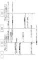
図9は、大量のDLデータが届き、UEがアイドルモードであって制御プレーンCIoTデータ転送のためにアタッチされた時の、CP CIoTからUP(CIoTまたはフルLTE)への切り替えを示す。 FIG. 9 shows a switch from CP CIoT to UP (CIoT or full LTE) when a large amount of DL data arrives and the UE is in idle mode and attached for control plane CIoT data transfer.
図9に示すステップを以下のように詳細に説明する。
1.CIoT可能なUE(CIoT機能を有するLTE UE、またはCIoT専用UE)はアタッチされ、制御プレーンCIoT最適化がデータ伝送のために設定されている。
2.下りデータが、P−GW機能エンティティに届く。あるいは、TDFが配備されている場合、DLデータはTDF、つまりこの機能エンティティで処理することができる。
3.P−GW(またはTDF)は、DPI(Deep Packet Inspection)を実行し、データの発信元(例えば、「App ID」によって識別される発信元アプリケーション)を識別することができる。P−GWは、DLパケットをS−GWに転送する。「App ID」は、DLパケットのGTP−Uヘッダに含めることができるし、あるいは、PGWとSGWとの間のGTP−Cプロトコル交換に含めることができる。
4.S−GWはDLパケットをバッファに格納し、可能な場合は、受信データサイズおよび送信者App IDを含めて、MMEに下りデータ通知を送信する。
5.MMEは、CP伝送またはUP伝送が適用可能であるかを判断するために受信したDDN要求を精査する。この目的のために、MMEはデータサイズをチェックして、制御プレーンを介したDLデータ配信を継続するか、あるいは、受信した下りデータが大量でありユーザプレーンを介して送信するほうが効率的である場合に利用可能なユーザプレーン(最適化されたCIoTユーザプレーンまたはLTEユーザプレーン)のうちの1つに切り替えるか、を評価する。また、MMEは、どの配信オプションを使用すべきか、すなわちCPとUPのどちらを使用すべきかを決定する際に、利用可能であれば、DLデータの起点(例えば、App ID)を考慮してもよい。
6.MMEは、S−GWに対してDDN確認応答でUEの呼び出しを確認応答する。
7.UEがアイドルモードである場合、MMEはUEを呼び出して、UEにサービス要求手順を実行させる。
8.MMEが(ステップ5におけるDLデータ評価に基づいて)UPデータ伝送を適用すると決定した場合、MMEは、S1−AP初期コンテキストセットアップ要求メッセージをRANノードに送信する。このステップは、データ無線ベアラ(DRB)をアクティベートする。MMEは、(NB−IoT RATの場合)UP CIoT使用のセットアップを明示的に指示するために、RANノードへの初期コンテキストセットアップ要求メッセージに「ユーザプレーンCIoT」指示を含めることができる。
9.RANノード(例えば、eNB)は、RRC接続再構成手順によって無線ベアラ確立を実行する。RANノードはまた、RRC接続再構成要求メッセージにおいて最適化されたCIoTユーザプレーンに対する優先をUEに示してもよい。
10.データ無線ベアラがセットアップされると、RANノードは、S1−APメッセージ初期コンテキストセットアップ完了をMMEに送信する。
注:初期コンテキストセットアップ手順が失敗した場合、あるいは、UEがステップ7で呼び出し手順の呼び出しに応答しない場合、MMEは下りデータ通知失敗指示メッセージをSGWに送信する。下りデータ通知失敗指示メッセージは、失敗の理由を示す新しい原因値を含むものとする。例えば、データサイズが制限値を超えている、制御プレーンからユーザプレーンへの切り替えが失敗する、など。
11.MMEは、受諾されたEPSベアラのTEIDを含むベアラ変更要求メッセージをS−GWに送信し、P−GWは、ベアラ変更応答で確認する。
12.こうして、ユーザプレーン(最適化されたCIoTまたはフルLTE)が確立され、DLデータを確立されたユーザプレーンを介してUEに配信することが可能になる。The steps shown in FIG. 9 will be described in detail as follows.
1. A CIoT-capable UE (an LTE UE having a CIoT function or a CIoT-only UE) is attached, and a control plane CIoT optimization is set for data transmission.
2. Downlink data arrives at the P-GW functional entity. Alternatively, if TDF is deployed, the DL data can be processed by TDF, this functional entity.
3. The P-GW (or TDF) can execute DPI (Deep Packet Inspection) and identify a data source (for example, a source application identified by “App ID”). The P-GW transfers the DL packet to the S-GW. The "App ID" can be included in the GTP-U header of the DL packet, or it can be included in the GTP-C protocol exchange between the PGW and the SGW.
4. The S-GW stores the DL packet in a buffer and, if possible, sends a downlink data notification to the MME, including the received data size and sender App ID.
5. The MME scrutinizes the received DDN request to determine if CP or UP transmission is applicable. For this purpose, it is more efficient for the MME to check the data size and continue DL data delivery via the control plane, or to receive a large amount of downlink data and send it via the user plane. Evaluate whether to switch to one of the available user planes (optimized CIoT user plane or LTE user plane). The MME may also consider the origin of DL data (eg, App ID), if available, in deciding which delivery option to use, ie, CP or UP. Good.
6. The MME acknowledges the call of the UE with a DDN acknowledgement to the S-GW.
7. When the UE is in idle mode, the MME calls the UE to let the UE perform the service request procedure.
8. If the MME decides (based on the DL data evaluation in step 5) to apply UP data transmission, the MME sends an S1-AP initial context setup request message to the RAN node. This step activates a data radio bearer (DRB). The MME may include a "user plane CIoT" indication in the initial context setup request message to the RAN node to explicitly indicate the setup of UP CIoT use (for NB-IoT RAT).
9. The RAN node (e.g., eNB) performs radio bearer establishment according to the RRC connection reconfiguration procedure. The RAN node may also indicate to the UE a priority for the optimized CIoT user plane in the RRC connection reconfiguration request message.
10. When the data radio bearer is set up, the RAN node sends an S1-AP message initial context setup complete to the MME.
Note: If the initial context setup procedure fails, or if the UE does not respond to the call of the calling procedure in step 7, the MME sends a downlink data notification failure indication message to the SGW. The downlink data notification failure instruction message shall include a new cause value indicating the reason for the failure. For example, the data size exceeds the limit, switching from the control plane to the user plane fails, etc.
11. The MME sends a bearer change request message including the TEID of the accepted EPS bearer to the S-GW, and the P-GW confirms with the bearer change response.
12. In this way, the user plane (optimized CIoT or full LTE) is established and the DL data can be delivered to the UE via the established user plane.
解決策2.2
UEがアイドルモードであって制御プレーンを用いたCIoT最適化が設定されている間の大量の非IPデータ配信のための制御プレーンCIoTからユーザプレーンCIoTへの切り替えSolution 2.2
Switching from control plane CIoT to user plane CIoT for large amount of non-IP data delivery while UE is in idle mode and CIoT optimization with control plane is set
図10は、大量のDL非IPデータが届いてUEがSCEFを介して制御プレーンCIoTデータ転送のためにアタッチされた時の、制御プレーンCIoTからユーザプレーン(CIoTまたはフルLTE)への切り替えを示す。 FIG. 10 shows switching from control plane CIoT to user plane (CIoT or full LTE) when a large amount of DL non-IP data arrives and the UE is attached for control plane CIoT data transfer via SCEF. ..
図10に示すステップを以下のように詳細に説明する。
1.CIoT可能なUE(CIoT機能を有するLTE UE、またはCIoT専用UE)は、制御プレーンCIoT最適化のためにアタッチされ、アイドルモードである。
2.非IPデータ配信要求がSCEFで受信される。
3.非IPデータ要求がSCEFによって承認される。SCEFは、非IPデータのサイズをチェックして、UEへの配信のために非IPデータサイズと非IPデータ自体とをMMEに提示する。
注:非IPデータサイズをSCS/ASからのNIDD配信要求に含めることが可能である。
4.MMEは、非IPデータサイズが制御プレーンを用いた少量データ伝送の制限内であるか否かを評価する。受信した下りデータが大量であり、ユーザプレーンを介してそのデータを送信する方が効率的である場合、UEによってサポートされるならば、MMEはCIoT最適化されたユーザプレーンまたはLTEユーザプレーンを確立すると決定してもよい。
5.UEがアイドルモードである場合、MMEはUEを呼び出し、UEはサービス要求を返す。
6.MMEは、S1−AP初期コンテキストセットアップ要求メッセージをRANノード(例えば、eNB)に送信する。MMEは、eNBとMMEとの間でS1ユーザプレーンが確立されるように、MMEによって割り当てられるS1ユーザプレーンTEIDを含める。このステップにより、無線ベアラおよびS1ベアラはアクティベートされる。MMEが(ステップ5のDLデータ評価に基づいて)最適化されたCIoTユーザプレーンを介してDLデータを配信すると決定した場合、MMEは、CIoT最適化ユーザプレーンタイプ配信の優先(または要求)を示すために、「ユーザプレーンCIoT」指示子を含める。
7.RANノードは、RRC接続再構成手順を用いて無線ベアラ確立を実行する。RANノード(例えば、eNB)は、RRC接続再構成要求メッセージにおいて、最適化されたCIoTユーザプレーンを優先することをUEに示してもよい。
8.ユーザプレーン無線ベアラがセットアップされると、RANノードは、MMEにS1−APメッセージ初期コンテキストセットアップ完了を送信する。MMEは、S1ユーザプレーンがMMEとeNBとの間に確立されると、ベアラ変更要求メッセージをS−GWに送信しない。初期コンテキストセットアップ手順が失敗した場合、またはUEがステップ5で呼び出し手順に対する呼び出しに応答しない場合、MMEはNIDD配信失敗指示メッセージをSCEFに送信する。NIDD配信失敗指示メッセージは、失敗の理由を示す新しい原因値を含むものとする。例えば、データサイズが限界を超えた、制御プレーンからユーザプレーンへの動的切り替えが失敗した、UEを呼び出すことができない、コンテキストが見つからない、中断(Suspension)によりUEを呼び出すことができない、UEが既に再アタッチされている、ハンドオーバ/TAU/RAU手順が進行中のため一時的に拒否されている、UEが応答していない、サービスが拒否されている、UEが既に再度アタッチされている、などである。SCEFがMMEからNIDD配信失敗指示メッセージを受信した場合、SCEFは、SCS/ASが配信失敗に対する適切な処置を取るために、NIDD配信失敗指示メッセージを新しい原因値をもってSCS/ASに送信する。新しい原因値とは、例えば、データサイズを超えた場合、制御プレーンからユーザプレーンへの動的切り替えが失敗する、UEを呼び出すことができない、コンテキストが見つからない、中断(Suspension)によりUEを呼び出すことができない、UEが既に再接続されている、ハンドオーバ/TAU/RAU手順が進行中のため一時的に拒否されている、UEが応答していない、サービスが拒否されている、UEが既に再接続しているなど。
9.こうして、ユーザプレーン(最適化されたCIoTまたはフルLTE)が確立され、DLデータをUEに配信することができる。The steps shown in FIG. 10 will be described in detail as follows.
1. CIoT-capable UEs (LTE UEs with CIoT capabilities or CIoT dedicated UEs) are attached for control plane CIoT optimization and are in idle mode.
2. A non-IP data delivery request is received at SCEF.
3. The non-IP data request is approved by the SCEF. The SCEF checks the size of the non-IP data and presents the non-IP data size and the non-IP data itself to the MME for delivery to the UE.
Note: Non-IP data size can be included in NIDD delivery request from SCS / AS.
4. The MME evaluates whether the non-IP data size is within the limits of small amount data transmission using the control plane. If there is a large amount of downlink data received and it is more efficient to send that data over the user plane, the MME will establish a CIoT optimized user plane or an LTE user plane if supported by the UE. Then you may decide.
5. If the UE is in idle mode, the MME calls the UE and the UE returns a service request.
6. The MME sends an S1-AP initial context setup request message to the RAN node (eg, eNB). The MME includes the S1 user plane TEID assigned by the MME so that the S1 user plane is established between the eNB and the MME. By this step, the radio bearer and S1 bearer are activated. If the MME decides to deliver DL data over the optimized CIoT user plane (based on the DL data evaluation in step 5), the MME indicates a priority (or request) for CIoT optimized user plane type delivery. For this purpose, a "user plane CIoT" indicator is included.
7. The RAN node performs radio bearer establishment using the RRC connection reconfiguration procedure. The RAN node (eg, eNB) may indicate to the UE in the RRC connection reconfiguration request message that it prioritizes the optimized CIoT user plane.
8. When the user plane radio bearer is set up, the RAN node sends an S1-AP message initial context setup complete to the MME. The MME does not send the bearer change request message to the S-GW when the S1 user plane is established between the MME and the eNB. If the initial context setup procedure fails or if the UE does not respond to the call for the call procedure in step 5, the MME sends a NIDD delivery failure indication message to the SCEF. The NIDD delivery failure indication message shall contain a new cause value indicating the reason for the failure. For example, the data size exceeds the limit, the dynamic switching from the control plane to the user plane has failed, the UE cannot be called, the context cannot be found, the UE cannot be called due to Suspension, the UE Already reattached, Temporarily rejected due to handover / TAU / RAU procedure in progress, UE not responding, service denied, UE already reattached, etc. Is. When the SCEF receives the NIDD delivery failure indication message from the MME, the SCEF sends the NIDD delivery failure indication message to the SCS / AS with a new cause value for the SCS / AS to take appropriate action for the delivery failure. The new cause value is, for example, when the data size is exceeded, the dynamic switching from the control plane to the user plane fails, the UE cannot be called, the context cannot be found, and the UE is called due to Suspension. Unable to do, the UE is already reconnected, is temporarily rejected because a handover / TAU / RAU procedure is in progress, the UE is not responding, service is denied, the UE is already reconnected Etc.
9. Thus, the user plane (optimized CIoT or full LTE) is established and DL data can be delivered to the UE.
解決策2.1および2.2では、下記の代替情報のうちの少なくとも1つを、データサイズ(または非IPデータサイズ)と交換できる。
a)最大スループットまたはデータレート(特定の期間(例えば、秒/時間/日/週)あたり)
b)最大伝送回数(特定の期間(例えば、秒/時間/日/週)あたり)
c)UEが受信する総データ量が閾値を上回る/下回るかどうかを示すフラグ。
また、代替情報として、a)〜c)のうちの2つ以上のパラメータと交換することができる。In solutions 2.1 and 2.2 at least one of the following alternatives can be exchanged for data size (or non-IP data size).
a) Maximum throughput or data rate (per specific time period (eg seconds / hours / days / weeks))
b) Maximum number of transmissions (per specific period (eg, seconds / hours / days / weeks))
c) A flag indicating whether the total amount of data received by the UE is above / below a threshold.
Also, as alternative information, two or more parameters of a) to c) can be exchanged.
上記の解決策2.1および2.2は、DLデータがMMEに届いた時にUEがアイドル状態にあると仮定する。さらに、他の解決策2.3を以下に説明する。この解決策では、DLデータがSGWまたはMMEに届いた時にUEが接続モードにあると仮定する。具体的には、CP伝送が設定され適用されているものとする。この解決策は、UEが接続モードにある間に無線インタフェース構成(すなわち、無線ベアラ)およびS1−Uベアラを変更することを提案する。 Solutions 2.1 and 2.2 above assume that the UE is idle when DL data arrives at the MME. Furthermore, another solution 2.3 is explained below. This solution assumes that the UE is in connected mode when DL data arrives at the SGW or MME. Specifically, it is assumed that CP transmission is set and applied. This solution proposes to change the radio interface configuration (ie radio bearer) and S1-U bearer while the UE is in connected mode.
図11に示すステップを以下のように詳細に説明する。
1.UEが接続状態である間、ユーザプレーンノードの1つ(RANノード、PGW、SGWのうちのいずれか)が、データサイズまたはデータ量が閾値を超えて増加していること、あるいは新しいアプリケーションがデータ伝送を開始したことを検出することができる。そのような検出にしたがって、SGW/PGWまたはRANノードは、ユーザプレーン上の変化した状況(増加したデータや、新しいアプリケーションなど)についてMMEに通知する。MME自体が、ユーザプレーン機能エンティティからの明示的な指示子を受けとることなく、増加したデータや開始された新しいアプリケーションを検出することも可能である。
例えば、ステップ1.1において、(図示しないが、PGWによって既に通知された)SGWが、GTP−Uヘッダ中にパケット長パラメータを示している、GTP−Uヘッダ中の新しいデータ/PDUサイズについてMMEに通知する。あるいは、SGWが、GTP−Cメッセージを使用して、新しいデータ量や新しいアプリケーション(例えば、App ID)について通知する。あるいは、ステップ1.2において、RANノードは、(例えば、特定の閾値を超えるバッファサイズに基づいて)SRB1/SRB2または制御プレーン上の増加したデータ伝送時間を検出することもできる。これは、限定されないが、制限された制御プレーン伝送帯域幅に好適に適用可能である。例えば、多くのIoT UEが同時にデータを受信し、RANノードの伝送バッファが増大しうることがあり、伝送遅延につながる。データPDUサイズが1.5キロバイト未満であり、SGW/PGWでは大量データとして検出されなかったとしても、eNBは、このような状況をMMEに示すことが可能である。そのような指示子の1つの例は、CP伝送チャネル/ベアラが、所与のセル内でサービスされる1つの特定のUEまたはすべてのUEのために、あるいは、所与のRANノードによって、過大な負荷をかけられることを意味する「CP負荷」である。このような検出にしたがって、RANノードは、変更されたデータ条件についてMMEに通知する。
2.MMEは、ユーザプレーン(RANノードまたはSGW/PGWのいずれか)から更新された情報を受信するか、あるいは、変更された状況を自ら検出した後で、使用されているCP伝送をUP伝送に切り替えるべきかどうかを判断することができる。MMEは、このようなCP伝送からUP伝送への切り替えが必要であると判断した場合、RANノード内のUEのコンテキストを変更する手順を、より具体的には、例えば、ASセキュリティのセットアップと可能なDRBの確立を変更する手順を開始する。例えば、S1−APベアラ変更手順を使用することができるが、RANノードにDRBおよびASセキュリティのアクティベーションを示す新しいパラメータを含めることができる。
3.MMEからの要求を受信すると、RANノード(例えば、eNB)は、まだ存在しない場合には、ASセットアップセキュリティセットアップを開始し、DRB(s)の確立を開始する。この目的のために、eNBはRRC接続再構成手順を使用することができる。
4.USはRRC接続再構成を確認する。
5.RANノード(eNB)は、正常な無線接続の変更についてMMEに応答する。
6.MMEは、SGWの再構成を実行する。この目的のために:
ステップ6.1において、MMEは、例えば、ベアラ変更要求手順を使用して、eNBのGTP−U TEIDでSGWを更新することによって、SGW GTP−U転送を再構成する。
ステップ6.2において、MMEは、S11インタフェースを介して既存のGTP−Uトンネル状態の解放を開始する。
オプションとして、コンバインドベアラ変更手順およびGTP−U解放手順を実行する新しいS11手順を指定してもよい。The steps shown in FIG. 11 will be described in detail as follows.
1. While the UE is in the connected state, one of the user plane nodes (RAN node, PGW, SGW) is increasing the data size or the amount of data beyond the threshold, or the new application is It is possible to detect that the transmission has started. Upon such detection, the SGW / PGW or RAN node informs the MME about the changed situation (increased data, new application, etc.) on the user plane. It is also possible for the MME itself to detect increased data or new applications started without receiving explicit directives from the user plane functional entity.
For example, in step 1.1, the SGW (not shown, already notified by the PGW) indicates the packet length parameter in the GTP-U header, the MME for the new data / PDU size in the GTP-U header. To notify. Alternatively, the SGW uses the GTP-C message to inform about the new data amount and the new application (for example, App ID). Alternatively, in step 1.2, the RAN node may detect an increased data transmission time on SRB1 / SRB2 or the control plane (eg, based on a buffer size above a certain threshold). This is preferably applicable to, but not limited to, limited control plane transmission bandwidth. For example, many IoT UEs may receive data at the same time, which may increase the transmission buffer of the RAN node, leading to transmission delay. Even if the data PDU size is less than 1.5 kilobytes and is not detected as a large amount of data by the SGW / PGW, the eNB can indicate such a situation to the MME. One example of such an indicator is that the CP transport channel / bearer is oversized for one particular UE or all UEs served in a given cell, or by a given RAN node. It is a "CP load" which means that a different load can be applied. Upon such detection, the RAN node informs the MME about the changed data condition.
2. The MME receives the updated information from the user plane (either the RAN node or the SGW / PGW) or switches the CP transmission used to the UP transmission after detecting the changed situation by itself. You can decide whether or not to do it. When the MME determines that it is necessary to switch from CP transmission to UP transmission, the MME can perform a procedure for changing the context of the UE in the RAN node, more specifically, for example, AS security setup Initiate a procedure to change the DRB establishment. For example, the S1-AP bearer change procedure may be used, but the RAN node may include new parameters indicating DRB and AS security activation.
3. Upon receiving the request from the MME, the RAN node (eg, eNB) initiates AS setup security setup and initiates DRB (s) establishment if it does not already exist. For this purpose, the eNB may use the RRC connection reconfiguration procedure.
4. The US confirms the RRC connection reconfiguration.
5. The RAN node (eNB) responds to the MME about a successful radio connection change.
6. The MME performs SGW reconfiguration. For this purpose:
In step 6.1, the MME reconfigures the SGW GTP-U transfer by updating the SGW with the GTP-U TEID of the eNB, eg using the bearer change request procedure.
In step 6.2, the MME initiates the release of the existing GTP-U tunnel state via the S11 interface.
Optionally, a new S11 procedure may be specified to perform the combined bearer change procedure and the GTP-U release procedure.
図11のように実行される手順の結果、ULデータおよびDLデータは、ユーザプレーン(NB−IoT UP最適化またはWB−EUTRAN UP伝送のいずれかを含む)を用いて伝送される。 As a result of the procedure performed as in FIG. 11, UL data and DL data are transmitted using the user plane (including either NB-IoT UP optimization or WB-EUTRAN UP transmission).
この解決策2.3で、UEが通常のように接続状態にい続けることが可能である一方、大量PDU処理が可能である。これにより、例えば、デタッチおよび再アタッチ手順を実行することに比べてシグナリングが低減する。 With this solution 2.3, it is possible for the UE to remain connected as usual, while allowing for large PDU processing. This reduces signaling compared to, for example, performing detach and reattach procedures.
さらなる実施形態では、接続モードのUEが、UEによって経験される悪い無線状態についてMMEに示すことが提案される。例えば、これは、UEがセルエッジに存在する場合(すなわち悪い無線状態、例えばUEが地下にある場合)に起こり得る。そのような場合、バッテリ電力を節約して到達可能性を確保するために、UEおよびネットワーク(MMS/SGSN)が以前に使用したUP伝送からCP伝送の使用を再選択することが提案される。
この目的のために、UEは、NASを介してMME/SGSNに悪い無線状態のシグナリングを示すことができる。別の代替案では、RANノードが悪い無線状態をMME/SGSNに示すことができる。MME/SGSNは、UP伝送からCP伝送に切り替えることによって無線接続の再構成を開始する。In a further embodiment, it is proposed that the UE in connected mode indicates to the MME about the bad radio conditions experienced by the UE. For example, this may occur if the UE is at the cell edge (ie bad radio conditions, eg the UE is underground). In such cases, it is proposed to reselect the use of CP transmissions from the UP transmissions previously used by the UE and the network (MMS / SGSN) in order to save battery power and ensure reachability.
For this purpose, the UE may indicate poor radio condition signaling to the MME / SGSN via NAS. In another alternative, the RAN node may indicate bad radio conditions to the MME / SGSN. The MME / SGSN initiates the reconfiguration of the wireless connection by switching from UP transmission to CP transmission.
解決策1の代替案は解決策2に適用可能である。 Alternatives to
以下の説明は、本発明に記載された全ての解決策に当てはまる。
本発明の実施形態によれば、移動体端末(例えば、UE)30は、ネットワークへの/からの(特に、RANノードからの)シグナリングに対応できるように変更される。移動体端末30は、図12に示すようなブロック図を用いて概略的に説明することができる。The following description applies to all the solutions described in the present invention.
According to embodiments of the present invention, the mobile terminal (eg UE) 30 is modified to accommodate signaling to / from the network (especially from the RAN node). The
図12に示すように、移動体端末(UE)30は、トランシーバ回路31と、ネットワーク(RANノード)と信号を送受信するための無線インタフェース32とを備える。移動体端末30は、自身の動作を制御するためのコントローラ33を備える。コントローラ33は、メモリ34に関連付けられている。 As shown in FIG. 12, a mobile terminal (UE) 30 includes a
ソフトウェアは、例えば、メモリ34に予めインストールされていてもよく、通信ネットワークを介して、または着脱可能なデータ記憶装置(RMD)からダウンロードされてもよい。コントローラ33は、この例では、メモリ34に格納されたプログラム命令またはソフトウェア命令によって移動体端末30の全体的な動作を制御するように構成される。図示のように、ソフトウェア命令は、とりわけ、オペレーティングシステム35および通信制御モジュール36を含む。 The software may be pre-installed in the
通信制御モジュール36は、移動体端末30とネットワークとの間の通信を制御する。通信制御モジュール36は、トランシーバ制御モジュール37を含む。 The
本発明の実施形態によれば、RANノード(例えば、eNB)40は、ネットワーク(MME/SGSN)への/からのシグナリングおよびUE30への/からのシグナリングに対応できるように変更される。RANノード40は、図13に示すようなブロック図を用いて概略的に説明することができる。 According to embodiments of the present invention, the RAN node (eg eNB) 40 is modified to accommodate signaling to / from the network (MME / SGSN) and to / from the
図13に示すように、RANノード40は、トランシーバ回路41と、サービングノードと信号を送受信するためのネットワークインタフェース42と、移動体端末30と信号を送受信するための無線インタフェース43とを備える。RANノード40は、自身の動作を制御するためのコントローラ44を備える。コントローラ44は、メモリ45に関連付けられている。 As shown in FIG. 13, the
ソフトウェアは、例えば、メモリ45に予めインストールされていてもよく、通信ネットワークを介して、または着脱可能なデータ記憶装置(RMD)からダウンロードされてもよい。コントローラ44は、この例では、メモリ45に格納されたプログラム命令またはソフトウェア命令によってRANノード40の全体的な動作を制御するように構成される。図示のように、ソフトウェア命令は、とりわけ、オペレーティングシステム46および通信制御モジュール47を含む。 The software may be pre-installed in the
通信制御モジュール47は、RANノード40と移動体端末30との間の通信、およびRANノード40とサービングノードとの間の通信を制御する。通信制御モジュール47は、トランシーバ制御モジュール48を含む。 The
本発明の実施形態によれば、サービングノード(MME/SGSN/MSC/C−SGN)50は、提案された解決策に従って動作することができるよう変更/拡張されるべきである。また、SGW、PGWおよびHSSへの変更が必要である。このために、サービングノード(MME/SGSN)50、SGW、PGW、SCEFまたはHSSは、図14のブロック図を用いて概略的に説明することができる。 According to the embodiments of the present invention, the serving node (MME / SGSN / MSC / C-SGN) 50 should be modified / extended to be able to operate according to the proposed solution. Also, changes to SGW, PGW and HSS are required. To this end, the serving node (MME / SGSN) 50, SGW, PGW, SCEF or HSS can be schematically described using the block diagram of FIG.
図14に示すように、サービングノード50は、トランシーバ回路51と、他のネットワークエンティティ(RANノード40)と信号を送受信するためのネットワークインタフェース52とを備える。サービングノード50は、自身の動作を制御するコントローラ53を備える。コントローラ53は、メモリ54に関連付けられている。 As shown in FIG. 14, the serving
ソフトウェアは、例えば、メモリ54に予めインストールされていてもよく、通信ネットワークを介して、または着脱可能なデータ記憶装置(RMD)からダウンロードされてもよい。コントローラ53は、この例では、メモリ54に格納されたプログラム命令またはソフトウェア命令によってサービングノード50の全体的な動作を制御するように構成される。図示のように、ソフトウェア命令は、とりわけ、オペレーティングシステム55および通信制御モジュール56を含む。 The software may be pre-installed in the
通信制御モジュール56は、サービングノード50と他のネットワークエンティティ(RANノード40)との間の通信を制御する。通信制御モジュール56は、トランシーバ制御モジュール57を含む。 The
本発明をその実施形態を参照して具体的に示し説明したが、本発明はこれらの実施形態に限定されるものではない。特許請求の範囲によって規定される本発明の精神および範囲から逸脱することなく、形式および詳細の様々な変更を行うことが可能なことは、当業者には理解されよう。 Although the present invention has been specifically shown and described with reference to the exemplary embodiments, the present invention is not limited to these exemplary embodiments. Those skilled in the art will appreciate that various changes in form and detail can be made without departing from the spirit and scope of the invention as defined by the claims.
本願は、2016年2月17日に特許出願された欧州特許出願EP16275027.7の特許出願に基づく優先権主張の利益を享受するものであり、当該特許出願に記載された内容は、全て本明細書に含まれるものとする。
The present application enjoys the benefit of the priority claim based on the patent application of European Patent Application EP16275027.7 filed on Feb. 17, 2016, and all contents described in the patent application are described in this specification. Included in the book.
Claims (9)
Translated fromJapanese前記第1のデータの送信後に受信した第2のデータのデータサイズに基づいて、以降のデータがユーザプレーンで移動体端末に送信されるかどうかを決定する決定手段と、
前記決定に基づいて、ユーザ装置コンテキストセットアップリクエストメッセージ(UE context setup request message)を無線アクセスネットワークノードへ送信する第2の通信手段と、
前記無線アクセスネットワークノードが無線ベアラを前記移動体端末に設定する際に、ユーザ装置コンテキストセットアップ完了メッセージ(UE context setup complete message)を前記無線アクセスネットワークノードから受信する受信手段と、
前記移動体端末とパケットデータネットワーク(PDN)ゲートウェイ(P-GW)との間のPDNコネクション用の、サービングゲートウェイ(S-GW)への認容されたベアラのためのトンネルエンドポイント識別子(Tunnel Endpoint Identifier (TEID))を含むリソース変更要求メッセージ(modify resources request message)を送信する第3の通信手段と、を備えるコアネットワークノード。Control plane CIoT (Cellular Internet of things) EPS (Evolved Packet System) and a first communication means for transmitting the first data using optimization,
Based on the data size of the second datareceived after the transmission of the first data, determining means for determining whether the subsequent data is transmitted to themobile terminal in the user plane,
Second communication means for transmitting a user equipment context setup request message (UE context setup request message) to the radio access network node based on the determination,
When the radio access network node to set the radio bearer tothe mobile terminal, receiving means for receiving user device context setup complete message (UE context setup complete message) from the radio access network node,
For a PDN connection between the mobile terminal and a Packet Data Network (PDN) Gateway (P-GW), a Tunnel Endpoint Identifier for an allowed bearer to a Serving Gateway (S-GW). (TEID)) and a third communication means for sending a modify resources request message (TEID)).
前記UE context setup complete messageはSI-AP Initial Context Setup Complete messageであり、
前記modify resources request messageはModify Bearer Request messageである、請求項1乃至3のいずれか1項に記載のコアネットワークノード。The UE context setup request message is S1-AP Initial Context Setup Request message,
The UE context setup complete message is SI-AP Initial Context Setup Complete message,
The core network node according to any one of claims 1 to3 , wherein the modify resources request message is a Modify Bearer Request message.
前記第1のデータの送信後に受信した第2のデータのデータサイズに基づいて、以降のデータがユーザプレーンで移動体端末に送信されるかどうかを決定し、
前記決定に基づいて、ユーザ装置コンテキストセットアップリクエストメッセージ(UE context setup request message)を無線アクセスネットワークノードへ送信し、
前記無線アクセスネットワークノードが無線ベアラを前記移動体端末に設定する際に、ユーザ装置コンテキストセットアップ完了メッセージ(UE context setup complete message)を前記無線アクセスネットワークノードから受信し、
前記移動体端末とパケットデータネットワーク(PDN)ゲートウェイ(P-GW)との間のPDNコネクション用の、サービングゲートウェイ(S-GW)への認容されたベアラのためのトンネルエンドポイント識別子(Tunnel Endpoint Identifier (TEID))を含むリソース変更要求メッセージ(modify resources request message)を送信する、通信制御方法。Control plane CIoT (Cellular Internet of things) EPS (Evolved Packet System) Sends the first data using optimization,
Based on the data size of the second datareceived after the transmission of the first data, determine whether the subsequent data is transmitted to themobile terminal in the user plane,
Sending a user equipment context setup request message (UE context setup request message) to the radio access network node based on the determination,
When the radio access network node to set the radio bearer tothe mobile terminal receives the user device context setup complete message (UE context setup complete message) from the radio access network node,
For a PDN connection between the mobile terminal and a Packet Data Network (PDN) Gateway (P-GW), a Tunnel Endpoint Identifier for an allowed bearer to a Serving Gateway (S-GW). A communication control method that sends a modify resources request message including (TEID)).
前記UE context setup complete messageはSI-AP Initial Context Setup Complete messageであり、
前記modify resources request messageはModify Bearer Request messageである、請求項5乃至7のいずれか1項に記載の通信方法。The UE context setup request message is S1-AP Initial Context Setup Request message,
The UE context setup complete message is SI-AP Initial Context Setup Complete message,
The communication method according to any one of claims5 to7 , wherein the modify resources request message is a Modify Bearer Request message.
コアネットワークノードは、
制御プレーンCIoT (Cellular Internet of things) EPS(Evolved Packet System)最適化を用いて第1のデータを送信する第1の通信手段と、
前記第1のデータの送信後に受信した第2のデータのデータサイズに基づいて、以降のデータがユーザプレーンで移動体端末に送信されるかどうかを決定する決定手段と、
前記決定に基づいて、ユーザ装置コンテキストセットアップリクエストメッセージ(UE context setup request message)を無線アクセスネットワークノードへ送信する第2の通信手段と、
前記無線アクセスネットワークノードが無線ベアラを前記移動体端末に設定する際に、ユーザ装置コンテキストセットアップ完了メッセージ(UE context setup complete message)を前記無線アクセスネットワークノードから受信する受信手段と、
前記移動体端末とパケットデータネットワーク(PDN)ゲートウェイ(P-GW)との間のPDNコネクション用の、サービングゲートウェイ(S-GW)への認容されたベアラのためのトンネルエンドポイント識別子(Tunnel Endpoint Identifier (TEID))を含むリソース変更要求メッセージ(modify resources request message)を送信する第3の通信手段と、を備え、
前記無線アクセスネットワークノードは、
前記ユーザプレーンCIoT indicationを含む前記UE context setup request messageを前記コアネットワークノードから受信する受信手段と、
前記移動体端末に前記無線ベアラを設定する設定手段と、
前記コアネットワークノードに前記UE context setup complete messageを送信する送信手段と、を備える、無線通信システム。Comprising a radio access network node and a core network node,
The core network node is
Control plane CIoT (Cellular Internet of things) EPS (Evolved Packet System) First communication means for transmitting the first data using optimization,
Based on the data size of the second datareceived after the transmission of the first data, the determining means for determining whether the subsequent data is transmitted to themobile terminal in the user plane,
Second communication means for transmitting a user equipment context setup request message (UE context setup request message) to the radio access network node based on the determination,
When the radio access network node to set the radio bearer tothe mobile terminal, receiving means for receiving user device context setup complete message (UE context setup complete message) from the radio access network node,
For a PDN connection between the mobile terminal and a Packet Data Network (PDN) Gateway (P-GW), a Tunnel Endpoint Identifier for an allowed bearer to a Serving Gateway (S-GW). (TEID)) including a third communication means for transmitting a resource modification request message (modify resources request message),
The radio access network node is
Receiving means for receiving the UE context setup request message including the user plane CIoT indication from the core network node,
Setting means for setting the radio bearer in the mobile terminal,
A wireless communication system, comprising: a transmitting unit that transmits the UE context setup complete message to the core network node.
Applications Claiming Priority (3)
| Application Number | Priority Date | Filing Date | Title |
|---|---|---|---|
| EP16275027 | 2016-02-17 | ||
| EP16275027.7 | 2016-02-17 | ||
| PCT/JP2017/004181WO2017141749A1 (en) | 2016-02-17 | 2017-02-06 | Selection of control plane and user plane for the data transmission |
Related Child Applications (1)
| Application Number | Title | Priority Date | Filing Date |
|---|---|---|---|
| JP2020068294ADivisionJP2020120392A (en) | 2016-02-17 | 2020-04-06 | Selection of control plane and user plane for data transmission |
Publications (2)
| Publication Number | Publication Date |
|---|---|
| JP2019511161A JP2019511161A (en) | 2019-04-18 |
| JP6696580B2true JP6696580B2 (en) | 2020-05-20 |
Family
ID=58108704
Family Applications (4)
| Application Number | Title | Priority Date | Filing Date |
|---|---|---|---|
| JP2018543258AActiveJP6696580B2 (en) | 2016-02-17 | 2017-02-06 | Control plane and user plane selection for data transmission |
| JP2020068294APendingJP2020120392A (en) | 2016-02-17 | 2020-04-06 | Selection of control plane and user plane for data transmission |
| JP2021171577AActiveJP7196983B2 (en) | 2016-02-17 | 2021-10-20 | Selection of control plane and user plane for data transmission |
| JP2022199482AActiveJP7485003B2 (en) | 2016-02-17 | 2022-12-14 | Control Plane and User Plane Selection for Data Transmission |
Family Applications After (3)
| Application Number | Title | Priority Date | Filing Date |
|---|---|---|---|
| JP2020068294APendingJP2020120392A (en) | 2016-02-17 | 2020-04-06 | Selection of control plane and user plane for data transmission |
| JP2021171577AActiveJP7196983B2 (en) | 2016-02-17 | 2021-10-20 | Selection of control plane and user plane for data transmission |
| JP2022199482AActiveJP7485003B2 (en) | 2016-02-17 | 2022-12-14 | Control Plane and User Plane Selection for Data Transmission |
Country Status (5)
| Country | Link |
|---|---|
| US (3) | US10616936B2 (en) |
| EP (1) | EP3417668B1 (en) |
| JP (4) | JP6696580B2 (en) |
| ES (1) | ES2922993T3 (en) |
| WO (1) | WO2017141749A1 (en) |
Families Citing this family (33)
| Publication number | Priority date | Publication date | Assignee | Title |
|---|---|---|---|---|
| US10893553B2 (en)* | 2016-01-14 | 2021-01-12 | Lg Electronics Inc. | Method for connecting with network at UE in wireless communication system and apparatus therefor |
| WO2017141749A1 (en)* | 2016-02-17 | 2017-08-24 | Nec Corporation | Selection of control plane and user plane for the data transmission |
| US10687202B2 (en)* | 2016-03-09 | 2020-06-16 | Lg Electronics Inc. | Method and device for configuring bearer for transmission of user data |
| US11044776B2 (en)* | 2016-03-27 | 2021-06-22 | Lg Electronics Inc. | Method for attempting network access from NB-IoT RAT |
| WO2017170122A1 (en)* | 2016-04-01 | 2017-10-05 | Nec Corporation | LOAD CONTROL FROM CONTROL PLANE CIoT EPS OPTIMISATION |
| WO2017189038A1 (en)* | 2016-04-29 | 2017-11-02 | Intel IP Corporation | CELLULAR IoT CONTROL AND USER PLANE SWITCHING |
| US10785696B2 (en) | 2016-06-21 | 2020-09-22 | Huawei Technologies Co., Ltd. | Systems and methods for user plane path selection, reselection, and notification of user plane changes |
| US10972552B2 (en)* | 2016-09-30 | 2021-04-06 | Huawei Technologies Co., Ltd. | Method and system for user plane path selection |
| US10531420B2 (en) | 2017-01-05 | 2020-01-07 | Huawei Technologies Co., Ltd. | Systems and methods for application-friendly protocol data unit (PDU) session management |
| US10917290B2 (en)* | 2017-02-22 | 2021-02-09 | Nokia Technologies Oy | Interface for a cloud radio access network |
| US10959066B2 (en)* | 2017-02-23 | 2021-03-23 | Nokia Technologies Oy | Method and system for access protocol optimization for narrow band Internet-of-Things devices within a network environment |
| WO2019057307A1 (en)* | 2017-09-25 | 2019-03-28 | Telefonaktiebolaget Lm Ericsson (Publ) | Data packet handling in a core network |
| JP6977153B2 (en)* | 2017-10-02 | 2021-12-08 | テレフオンアクチーボラゲット エルエム エリクソン(パブル) | Access stratum security in wireless communication systems |
| WO2019075748A1 (en) | 2017-10-20 | 2019-04-25 | Telefonaktiebolaget Lm Ericsson (Publ) | Configuration of a packet data network connection |
| CN108055660B (en)* | 2017-12-13 | 2021-03-30 | 青岛海信移动通信技术股份有限公司 | Method for transmitting data in network channel and Internet of things terminal |
| JP2019125844A (en)* | 2018-01-12 | 2019-07-25 | シャープ株式会社 | User device |
| WO2019160549A1 (en)* | 2018-02-15 | 2019-08-22 | Nokia Technologies Oy | Coordinated selection of ran and core user plane components in a wireless communications network |
| JP7123607B2 (en)* | 2018-04-09 | 2022-08-23 | シャープ株式会社 | User device, control device, and communication control method |
| US11304244B2 (en)* | 2018-05-04 | 2022-04-12 | Telefonaktiebolaget Lm Ericsson (Publ) | Devices and methods for connection establishment in wireless network |
| US11323948B2 (en)* | 2018-07-24 | 2022-05-03 | T-Mobile Usa, Inc. | Device management for NB-IoT devices |
| EP3857935A4 (en) | 2018-09-24 | 2023-01-04 | Nokia Technologies Oy | SYSTEMS AND PROCEDURES FOR SECURITY PROTECTION OF NAS MESSAGES |
| WO2020068149A1 (en)* | 2018-09-25 | 2020-04-02 | Hughes Network Systems, Llc | Efficient transport of internet of things (iot) traffic in terrestrial wireless and satellite networks |
| WO2020223898A1 (en)* | 2019-05-07 | 2020-11-12 | Oppo广东移动通信有限公司 | Information transmission method and apparatus, and network device |
| JP7326860B2 (en)* | 2019-05-17 | 2023-08-16 | 富士フイルムビジネスイノベーション株式会社 | system, program |
| KR102751536B1 (en)* | 2019-06-07 | 2025-01-07 | 삼성전자주식회사 | Electronic device and system for the same |
| BR112022002629A2 (en)* | 2019-08-14 | 2022-05-03 | Zte Corp | Network reselection for split network sharing architecture |
| US12185157B2 (en)* | 2019-09-18 | 2024-12-31 | Telefonaktiebolaget Lm Ericsson (Publ) | Subscriber/service based radio access network reliability |
| WO2021243518A1 (en)* | 2020-06-01 | 2021-12-09 | Nokia Shanghai Bell Co., Ltd. | Initial access of remote device via relay |
| US11736349B2 (en)* | 2020-08-19 | 2023-08-22 | Verizon Patent And Licensing Inc. | Systems and methods for providing firmware over-the-air delivery to internet of things user equipment |
| CN114125910B (en)* | 2020-08-31 | 2025-02-25 | 华为技术有限公司 | Tunnel keep-alive method, network device, system and storage medium |
| WO2023004769A1 (en)* | 2021-07-30 | 2023-02-02 | Oppo广东移动通信有限公司 | Data transmission method and apparatus, and terminal and network device |
| US20230337120A1 (en)* | 2022-04-13 | 2023-10-19 | T-Mobile Usa, Inc. | Serving gateway selection based on packet data network type |
| GB202211689D0 (en)* | 2022-08-10 | 2022-09-21 | Samsung Electronics Co Ltd | External exposure of control plane to user plane switch parameter |
Family Cites Families (25)
| Publication number | Priority date | Publication date | Assignee | Title |
|---|---|---|---|---|
| EP2509345A1 (en) | 2011-04-05 | 2012-10-10 | Panasonic Corporation | Improved small data transmissions for machine-type-communication (MTC) devices |
| JP5904206B2 (en) | 2011-09-30 | 2016-04-13 | 日本電気株式会社 | Communication system, communication method, and communication program |
| IN2015DN01108A (en)* | 2012-09-12 | 2015-06-26 | Nec Corp | |
| US9049588B2 (en)* | 2013-02-28 | 2015-06-02 | Blackberry Limited | Communicating data in a predefined transmission mode |
| US9265085B2 (en)* | 2013-12-31 | 2016-02-16 | Alcatel Lucent | Methods and systems for optimizing short data burst services over an LTE network |
| US9877141B2 (en)* | 2014-06-24 | 2018-01-23 | Telefonaktiebolaget Lm Ericsson (Publ) | Management of wireless devices in limited radio coverage |
| KR102224447B1 (en) | 2014-07-03 | 2021-03-08 | 콘비다 와이어리스, 엘엘씨 | Application data delivery service for networks supporting multiple transport mechanisms |
| WO2016182580A1 (en)* | 2015-05-14 | 2016-11-17 | Nokia Technologies Oy | Bearer setup in dual connectivity |
| US10231089B2 (en)* | 2015-06-23 | 2019-03-12 | Lg Electronics Inc. | Method for managing area of terminal in wireless communication system and apparatus therefor |
| WO2017003235A1 (en)* | 2015-06-30 | 2017-01-05 | 엘지전자(주) | Method for group message transmission in wireless communication system and apparatus therefor |
| US20180220289A1 (en)* | 2015-07-28 | 2018-08-02 | Lg Electronics Inc. | Method for managing plurality of location areas in wireless communication system and apparatus therefor |
| EP3332577B1 (en)* | 2015-08-07 | 2020-04-29 | Samsung Electronics Co., Ltd. | Terminal and communication method of the same |
| EP3334227B1 (en)* | 2015-08-31 | 2020-10-07 | Huawei Technologies Co., Ltd. | Paging method and apparatus for distributed gateway |
| CN108141751B (en)* | 2015-09-24 | 2021-11-02 | 三星电子株式会社 | Method for supporting lawful interception of remote proximity service UEs in a network |
| US10225768B2 (en)* | 2015-11-04 | 2019-03-05 | Lg Electronics Inc. | Serving node relocating method in wireless communication system and device for same |
| EP3346753B1 (en)* | 2015-11-06 | 2020-04-29 | Samsung Electronics Co., Ltd. | Method for transmitting data in ciot system and device therefor |
| WO2017099464A1 (en)* | 2015-12-07 | 2017-06-15 | 엘지전자 주식회사 | Method for performing s1 connection release by mobility management object, mobility management object, method for performing s1 connection release by base station, and base station |
| WO2017105077A1 (en)* | 2015-12-15 | 2017-06-22 | 엘지전자 주식회사 | User equipment and data reception method, and network node and data transmission method |
| WO2017116115A1 (en)* | 2015-12-29 | 2017-07-06 | 엘지전자 주식회사 | Method and device for establishing bearer for transmission of user data |
| US10652085B2 (en)* | 2016-01-07 | 2020-05-12 | Lg Electronics Inc. | Method for setting configuration of non-IP data delivery (NDID) in wireless communication system and device for same |
| CN106961456B (en)* | 2016-01-11 | 2022-01-18 | 北京三星通信技术研究有限公司 | IOT service determining method and device and IOT service behavior control method and device |
| EP3403465A1 (en)* | 2016-01-12 | 2018-11-21 | Intel Corporation | CELLULAR INTERNET OF THINGS (CIoT) OPTIMIZATIONS FOR NARROWBAND (NB) AND NON-NB IoT NETWORKS |
| WO2017126928A1 (en)* | 2016-01-20 | 2017-07-27 | 엘지전자 주식회사 | Method for changing connection mode and mobility management entity |
| US10932224B2 (en)* | 2016-01-21 | 2021-02-23 | Lg Electronics Inc. | Method and user equipment for receiving data, and method and base station for transmitting data |
| WO2017141749A1 (en)* | 2016-02-17 | 2017-08-24 | Nec Corporation | Selection of control plane and user plane for the data transmission |
- 2017
- 2017-02-06WOPCT/JP2017/004181patent/WO2017141749A1/ennot_activeCeased
- 2017-02-06USUS15/755,927patent/US10616936B2/enactiveActive
- 2017-02-06JPJP2018543258Apatent/JP6696580B2/enactiveActive
- 2017-02-06EPEP17706906.9Apatent/EP3417668B1/enactiveActive
- 2017-02-06ESES17706906Tpatent/ES2922993T3/enactiveActive
- 2020
- 2020-03-05USUS16/810,384patent/US10945300B2/enactiveActive
- 2020-04-06JPJP2020068294Apatent/JP2020120392A/enactivePending
- 2021
- 2021-01-21USUS17/154,790patent/US12028912B2/enactiveActive
- 2021-10-20JPJP2021171577Apatent/JP7196983B2/enactiveActive
- 2022
- 2022-12-14JPJP2022199482Apatent/JP7485003B2/enactiveActive
Also Published As
| Publication number | Publication date |
|---|---|
| US20180352593A1 (en) | 2018-12-06 |
| US12028912B2 (en) | 2024-07-02 |
| JP7485003B2 (en) | 2024-05-16 |
| US10945300B2 (en) | 2021-03-09 |
| JP2023030016A (en) | 2023-03-07 |
| JP2020120392A (en) | 2020-08-06 |
| US20200236723A1 (en) | 2020-07-23 |
| US20230093775A9 (en) | 2023-03-23 |
| WO2017141749A1 (en) | 2017-08-24 |
| US20220117016A1 (en) | 2022-04-14 |
| ES2922993T3 (en) | 2022-09-22 |
| JP2019511161A (en) | 2019-04-18 |
| EP3417668B1 (en) | 2022-07-06 |
| JP7196983B2 (en) | 2022-12-27 |
| JP2022009292A (en) | 2022-01-14 |
| EP3417668A1 (en) | 2018-12-26 |
| US10616936B2 (en) | 2020-04-07 |
Similar Documents
| Publication | Publication Date | Title |
|---|---|---|
| JP7485003B2 (en) | Control Plane and User Plane Selection for Data Transmission | |
| JP7306511B2 (en) | Load control with control plane CIoT EPS optimization | |
| US9674830B2 (en) | Method for processing data associated with session management and mobility management | |
| US10869342B2 (en) | Radio bearer establishment method and base station | |
| CN101594285B (en) | Method, device and system for using polymerizing maximal bit rate | |
| KR101751654B1 (en) | Systems for switching modes in wireless sessions | |
| US11272399B2 (en) | Data processing method, mobility management device, and terminal device | |
| US20150049719A1 (en) | Method and Apparatus for Establishing Direct Tunnel | |
| US9860792B2 (en) | Network device for supporting gateway change in mobile communication system, and method for operating same | |
| KR101449720B1 (en) | Method And Apparatus for Reducing Bearer Setup Time | |
| US20250287279A1 (en) | Notification of sgw change for one or more pdn connections when combined sgw/pgw/smf set is deployed | |
| WO2015144213A1 (en) | Methods and nodes for improved network signaling |
Legal Events
| Date | Code | Title | Description |
|---|---|---|---|
| A521 | Request for written amendment filed | Free format text:JAPANESE INTERMEDIATE CODE: A523 Effective date:20181012 | |
| A621 | Written request for application examination | Free format text:JAPANESE INTERMEDIATE CODE: A621 Effective date:20181012 | |
| A977 | Report on retrieval | Free format text:JAPANESE INTERMEDIATE CODE: A971007 Effective date:20190718 | |
| A131 | Notification of reasons for refusal | Free format text:JAPANESE INTERMEDIATE CODE: A131 Effective date:20190820 | |
| A521 | Request for written amendment filed | Free format text:JAPANESE INTERMEDIATE CODE: A523 Effective date:20191001 | |
| TRDD | Decision of grant or rejection written | ||
| A521 | Request for written amendment filed | Free format text:JAPANESE INTERMEDIATE CODE: A523 Effective date:20200319 | |
| A01 | Written decision to grant a patent or to grant a registration (utility model) | Free format text:JAPANESE INTERMEDIATE CODE: A01 Effective date:20200324 | |
| A61 | First payment of annual fees (during grant procedure) | Free format text:JAPANESE INTERMEDIATE CODE: A61 Effective date:20200406 | |
| R150 | Certificate of patent or registration of utility model | Ref document number:6696580 Country of ref document:JP Free format text:JAPANESE INTERMEDIATE CODE: R150 |