JP6695222B2 - Fluid equipment connection structure - Google Patents
Fluid equipment connection structureDownload PDFInfo
- Publication number
- JP6695222B2 JP6695222B2JP2016129730AJP2016129730AJP6695222B2JP 6695222 B2JP6695222 B2JP 6695222B2JP 2016129730 AJP2016129730 AJP 2016129730AJP 2016129730 AJP2016129730 AJP 2016129730AJP 6695222 B2JP6695222 B2JP 6695222B2
- Authority
- JP
- Japan
- Prior art keywords
- locking
- connection structure
- connecting member
- fluid device
- divided piece
- Prior art date
- Legal status (The legal status is an assumption and is not a legal conclusion. Google has not performed a legal analysis and makes no representation as to the accuracy of the status listed.)
- Active
Links
Images


Landscapes
- Flanged Joints, Insulating Joints, And Other Joints (AREA)
- Clamps And Clips (AREA)
- Gasket Seals (AREA)
Description
Translated fromJapanese本発明は、第1接続部を有する第1流体機器と、第2接続部を有する第2流体機器と、第1接続部及び第2接続部を接続する環状シール部材と、第1接続部及び第2接続部の接続状態を維持する連結部材と、を有し、連結部材は、第1分割片と第2分割片を備え、第1分割片と第2分割片の一端に回動可能な連結部を設けた流体機器接続構造に関するものである。 The present invention relates to a first fluid device having a first connecting portion, a second fluid device having a second connecting portion, an annular seal member connecting the first connecting portion and the second connecting portion, a first connecting portion, and A connecting member that maintains the connection state of the second connecting portion, the connecting member includes a first divided piece and a second divided piece, and the first divided piece and the second divided piece are rotatable at one end thereof. The present invention relates to a fluid device connection structure provided with a connecting portion.
従来、半導体製造工程や液晶製造工程などの薬液の制御には、流量制御弁や開閉弁などのバルブ類や、フィルタ、圧力センサや流量センサなどのセンサ類、継手ブロックや流路ブロックなどの配管ブロック類など、流体機器が使用される。近年、装置のコンパクト化のため、これら流体機器の接続部同士を、連結部材を用いて直接連結し、ユニット化することが行われている。 Conventionally, for controlling chemicals in semiconductor manufacturing processes and liquid crystal manufacturing processes, valves such as flow control valves and on-off valves, filters, sensors such as pressure sensors and flow sensors, piping such as joint blocks and flow path blocks, etc. Fluid devices such as blocks are used. In recent years, in order to make the device compact, the connecting portions of these fluid devices have been directly connected using a connecting member to form a unit.
図59は、従来の流体機器接続構造100の断面図である。図57は、図59のQQ断面図である。図58は、従来の流体機器接続構造100の連結部材106の増し締め状態の断面図である。
従来の流体機器接続構造100は、図59に示すように、第1及び第2流体機器101、102の第1及び第2接続部103、104を、環状シール部材105を介して接続し、第1及び第2接続部103、104の外周に連結部材106を取り付けて接続状態を維持する。連結部材106は、図57に示すように、第1分割片107と第2分割片108の両端部を係合させて構成されている。FIG. 59 is a cross-sectional view of a conventional fluid
As shown in FIG. 59, the conventional fluid
図59に示すように、第1分割片107は、第1接続部103の外周に形成された第1装着溝103aに配置される第1突部107aと、第2接続部104の外周に形成された第2装着溝104aに配置される第2突部107bとを有する。また、第2分割片108は、第1装着溝103aに配置される第1突部108aと、第2装着溝104aに配置される第2突部108bとを有する。
図57に示すように、第1及び第2分割片107、108の一端は、支軸111を介して回動可能に係合されている。一方、第1及び第2分割片107、108の他端は、第2分割片108の第1延設部108cに突設した係止爪108eを第1分割片107の第2延設部107cに形成した挿通孔107eに弾性変形させながら挿通した後、係止爪108eを復元させて第2延設部107cに係止させることにより、係合される。As shown in FIG. 59, the first divided
As shown in FIG. 57, one ends of the first and second divided
このような連結部材106は、支軸111を基点にして第1分割片107を第2分割片108に対して回動させ、係止爪108eを挿通孔107eに挿通して第2延設部107cに係止させることにより、第1及び第2分割片107、108の第1及び第2突部107a、107b、108a、108bを第1及び第2接続部103、104の第1及び第2装着溝103a、104aに配置する。第1及び第2接続部103、104は、外力が加わると互いに離れる方向へ移動しようとするが、第1及び第2装着溝103a、104aの端面側内側面が連結部材106の第1及び第2突部107a、107b、108a、108bに支持されて移動を制限され、接続状態が維持される。この接続状態が、連結部材106で第1及び第2接続部103、104を接続する通常使用状態である。 In such a connecting
第1及び第2接続部103、104と環状シール部材105と第1及び第2分割片107、108は、樹脂を材質とする。そのため、例えば、第1及び第2接続部103、104に高温の薬液と低温の純水を交互に流すと、第1及び第2接続部103、104がクリープ変形し、シール力が低下することがある。シール力が低下すると、液漏れが生じる。このような緊急時に、増し締めが行われる。 The first and second connecting
連結部材106は、第1及び第2分割片107、108の第1及び第2突部107a、107b、108a、108bの先端部に第1及び第2連結側テーパ面107f、107g、108f、108gを設けている。そして、第1及び第2接続部103、104には、第1及び第2連結側テーパ面107f、107g、108f、108gに摺接する第1及び第2接続側テーパ面103b、104bが、第1及び第2フランジ103c、104cに設けられている。さらに、図58に示すように、連結部材106には、第1及び第2分割片107、108を互いに近づけて第1及び第2接続部103、104を引き寄せ、シール力を増加させるための増し締め部材110が取り付けられるようになっている。 The connecting
増し締め部材110を第1分割片107の挿通孔107dに挿通して第2分割片108のボルト孔108dに締め付けることにより、第1及び第2分割片107、108を引き寄せて第1及び第2連結側テーパ面107f、107g、108f、108gを第1及び第2接続部103、104の第1及び第2接続側テーパ面103b、104bに摺接させ、第1及び第2接続部103、104を近づける。よって、流体機器接続構造100は、増し締め部材110を用いて締め付けることで、シール力を向上させることができる。 By inserting the additional tightening
しかしながら、従来の流体機器接続構造100には、次のような問題があった。
異常なクリープなどによりシール力が低下して、液漏れが生じると、緊急対応として、増し締め部材110を挿通孔107dとボルト孔108dに締め付ける増し締めが行われる。しかし、増し締め部材110を取りに行く手間がかかる。また、増し締め部材110による増し締め手段に気付かないこともある。ここで、半導体製造工程等で使用される薬液は、腐食性が高く、危険度の高いものがある。そのような場合、早急に漏れを止める必要があるが、従来の流体機器接続構造100では、手間がかかり、早急な対応が取れない問題があった。
また、増し締め部材110を用いて増し締めを行う際、増し締め部材110を強く締めすぎる恐れがあり、強く締めすぎると部材が破損して、別の漏れが発生する恐れがあり、問題であった。However, the conventional fluid
When the sealing force is reduced due to abnormal creep and liquid leakage occurs, as an emergency measure, the additional tightening
Further, when performing the retightening using the
本発明は、上記問題点を解決するためのものであり、液漏れ発生時に早急な対応を可能とし、部材の変形の恐れのない流体機器接続構造を提供することを目的とする。 The present invention is intended to solve the above problems, and an object of the present invention is to provide a fluid device connection structure capable of promptly responding to the occurrence of a liquid leak and having no risk of member deformation.
上記課題を解決するために、本発明の流体機器接続構造は、次のような構成を有している。
(1)第1接続部を有する第1流体機器と、第2接続部を有する第2流体機器と、第1接続部及び第2接続部を接続する環状シール部材と、第1接続部及び第2接続部の接続状態を維持する連結部材と、を有し、連結部材は、第1分割片と第2分割片を備え、第1分割片と第2分割片の一端に回動可能な連結部を設けた流体機器接続構造において、第1分割片は、第1係止部を備え、第2分割片は、第1係止部が係止する第1係止受け部を備え、連結部材は、第1係止部と第1係止受け部が係合する第1係止位置を備えること、第1分割片または第2分割片の一方は、第2係止部を備え、第1分割片または第2分割片の他方は、第2係止部が係止する第2係止受け部を備え、連結部材は、第2係止部と第2係止受け部が係合する第2係止位置を備えること、連結部材は、第1係止位置にあるときよりも、第2係止位置にあるときの方が、環状シール部材方向に近づいていること、連結部材が第1係止位置にあるときは、第1係止部と第1係止受け部のみが係合しており、連結部材が第2係止位置にあるときは、第2係止部と第2係止受け部のみが係合していること、を特徴とする。
(2)(1)に記載の流体機器接続構造において、第1係止位置にあるとき、第2係止部の先端にある第2段差部は、環状シール部材の軸方向と直交する方向から目視できない位置にあること、を特徴とする。In order to solve the above problems, the fluid device connection structure of the present invention has the following configuration.
(1) A first fluid device having a first connection portion, a second fluid device having a second connection portion, an annular seal member connecting the first connection portion and the second connection portion, a first connection portion and a first And a connecting member that maintains the connection state of the two connecting portions, the connecting member including a first divided piece and a second divided piece, and the first divided piece and the second divided piece are rotatably connected to one end. In the fluid device connection structure provided with a portion, the first split piece includes a first locking portion, and the second split piece includes a first locking receiving portion with which the first locking portion locks, and a connecting member. Has a first locking position where the first locking portion and the first locking receiving portion engage with each other, and one of the first divided piece or the second divided piece has a second locking portion, and The other of the split piece or the second split piece includes a second locking receiving portion that is locked by the second locking portion, and the connecting member is a first locking portion that engages the second locking portion and the second locking receiving portion. 2 the locking position is provided, the connecting member is closer to the annular seal member direction when it is in the second locking position than when it is in the first locking position,and the connecting member is the first When in the locking position, only the first locking part and the first locking receiving part are engaged, and when the connecting member is in the second locking position, the second locking part and the second locking part are engaged. Only the stopper portion is engaged .
(2) In the fluid device connection structure according to (1), when in the first locking position, the second stepped portion at the tip of the second locking portion is from a direction orthogonal to the axial direction of the annular seal member. It is characterized by being in a position where it cannot be seen.
(3)(1)または(2)に記載の流体機器接続構造において、第2係止部と第2係止受け部の当接面は、傾きが設けられていること、を特徴とする。
(4)(1)乃至(3)のいずれか一つに記載の流体機器接続構造において、第1係止部と第2係止部のうち少なくとも一方は対に設けられていること、を特徴とする。
(5)(1)乃至(3)のいずれか一つに記載の流体機器接続構造において、第1係止部の当接面と第2係止部の当接面は、互いに直交する関係にあること、を特徴とする。
(6)(1)乃至(3)のいずれか一つに記載の流体機器接続構造において、第1分割片または第2分割片に設けられた挿通孔を第1係止部が通過する際、挿通孔が広がり、第1係止部が通過後に挿通孔は元の形状に戻ること、を特徴とする。(3) In the fluid device connection structure according to (1) or (2), the abutting surfaces of the second locking portion and the second locking receiving portion are inclined.
(4) In the fluid device connection structure according to any one of (1) to (3), at least one of the first locking portion and the second locking portion is provided in a pair. And
(5) In the fluid device connection structure according to any one of (1) to (3), the contact surface of the first locking portion and the contact surface of the second locking portion are orthogonal to each other. There is a feature.
(6) In the fluid device connection structure according to any one of (1) to (3), when the first locking portion passes through an insertion hole provided in the first divided piece or the second divided piece, The insertion hole expands, and the insertion hole returns to its original shape after the first locking portion has passed.
本発明の流体機器接続構造の作用・効果を説明する。
上記(1)の構成によれば、第2係止位置に保持するための部材を必要とせず、連結部材を第1係止位置から第2係止位置に移動するだけで保持まで完了し、緊急時に早急な対応ができ、ボルトによる増し締めの締めすぎにより部材が変形する恐れがない。また、特別な治具を必要としないため、緊急時に早急な対応ができる。The operation and effect of the fluid device connection structure of the present invention will be described.
According to the configuration of (1) above, a member for holding the second locking position is not required, and the holding is completed only by moving the connecting member from the first locking position to the second locking position. Immediate response is possible in an emergency, and there is no risk of the members being deformed by overtightening with bolts. In addition, since no special jig is required, it is possible to respond promptly in an emergency.
上記(2)の構成によれば、通常使用状態の締め付けである第1係止位置で係止が完了した時に、第2係止位置における構造は外観から見え難いため、第2係止位置を意識することがない。そのため、第2係止位置まで締め付けようとすることを抑制できる。これにより、誤って通常使用時に第2係止位置まで締め付けてしまうことを抑制することができる。
上記(3)の構成によれば、第2係止部と第2係止受け部は、その角度により連結部材が開こうとする力が働くとさらに強く係合しあう方向に力が働く。増し締め状態を維持する第2係止位置では、環状シール部材の反発力により接続部同士が互いに離れる方向へ移動しようとするため、このことが有効に働く。According to the configuration of (2) above, when the locking is completed at the first locking position which is the tightening in the normal use state, the structure at the second locking position is hard to see from the outside, so that the second locking position is There is no awareness. Therefore, it is possible to suppress trying to tighten up to the second locking position. This can prevent the user from accidentally tightening the second locking position during normal use.
According to the configuration of (3), when the second locking portion and the second locking receiving portion exert a force to open the connecting member due to the angle, a force acts in a stronger engaging direction. At the second locking position where the retightening state is maintained, the repulsive force of the annular seal member tries to move the connecting portions in a direction away from each other, which works effectively.
上記(4)の構成によれば、係止部は対になっているため、係止部に意図せず触れてしまい、一方の係止部が外れた場合にも、他方の係止部は係止されており、連結部材が外れることを防ぐことができる。
上記(5)の構成によれば、係止部と係止受け部をコンパクトに配置することができ、連結部材自体をコンパクトにすることができる。
上記(6)の構成によれば、第1係止部を外すためには、挿入時のテーパを利用することができず、挿通孔を押し広げるための比較的大きな力が必要となるため、容易に外れることはなく、誤操作外れを防止することができる。According to the above configuration (4), since the locking portions are paired, the locking portions are inadvertently touched, and even when one of the locking portions is disengaged, the other locking portion is not Since it is locked, the connecting member can be prevented from coming off.
According to the above configuration (5), the locking portion and the locking receiving portion can be arranged compactly, and the connecting member itself can be made compact.
According to the configuration of (6) above, in order to release the first locking portion, the taper at the time of insertion cannot be used, and a relatively large force for expanding the insertion hole is required. It does not come off easily, and it is possible to prevent accidental removal.
<第1実施形態>
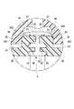
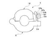
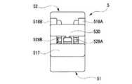
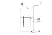
本発明の流体機器接続構造1の第1実施形態について、図面を参照しながら以下に詳細に説明する。図1は、第1実施形態の流体機器接続構造1の連結部材5が第1係止位置にあるときの平面図である。図2は、図1のAA断面図で、図3は、図2のCC断面図、図4は、図3のD部拡大図、図5は、図1のBB断面図である。図6は、連結部材5が第1係止位置にあるときの正面図で、図7は、その右側面図、図8は、その左側面図、図9は、その底面図、図10は、その斜視図である。なお、背面図は、正面図と対称であるため、省略する。
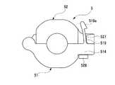
図11は、連結部材5が第2係止位置にあるときの平面図である。図12は、図10のEE断面図で、図13は、図12のGG断面図、図14は、図10のFF断面図である。図15は、連結部材5が第2係止位置にあるときの正面図で、図16は、その右側面図、図17は、その左側面図、図18は、その斜視図である。図19は、連結部材5が係止していない開いた状態にあるときの正面図である。
ここで、連結部材5の第1係止位置では、通常使用状態を示し、第2係止位置では、増し締め状態を示す。
なお、一対の部材について、A、Bの符号を用いて説明しているが、説明が煩雑になるため、適宜省略して説明する。<First Embodiment>
A first embodiment of a fluid device connection structure 1 of the present invention will be described below in detail with reference to the drawings. FIG. 1 is a plan view when the connecting
FIG. 11 is a plan view when the connecting
Here, the first locking position of the connecting
It should be noted that although the pair of members have been described using the reference numerals A and B, the description will be complicated and will be omitted as appropriate.
(流体機器接続構造の構成)
はじめに流体機器接続構造1の全体的な構成について説明する。
図3に示すように、流体機器接続構造1は、第1及び第2流体機器2、3の第1及び第2接続部21、31を、環状シール部材4を介して接続し、第1及び第2接続部21、31の外周に連結部材5を取り付けて接続状態を維持する。第1及び第2接続部21、31は、円筒状に構成されている。第1接続部21には流路29が形成され、第2接続部31には流路39が形成されている。
環状シール部材4は、PFA、PTFEなどの比較的硬くて耐腐食性があるフッ素樹脂を材質とする。環状シール部材4は、図4に示すように、本体部43と、本体部43の外周面から外径方向に張り出す張出部44と、張出部44の外周縁部に設けられた把持部45とを備える。本体部43には、環状シール溝46、47が形成されている。(Structure of fluid device connection structure)
First, the overall configuration of the fluid device connection structure 1 will be described.
As shown in FIG. 3, the fluid device connection structure 1 connects the first and
The
第1接続部21の環状シール部材4を装着する面には、端面22が形成されている。端面22には、外径方向に突出した係止凸部27が形成されている。端面22の内側には、本体部43の環状シール溝46に装着される圧入部24が形成されている。流路29方向の外周面には、連結部材5を装着するための装着溝23が環状に形成されている。端面22と装着溝23との間には、フランジ部25が設けられている。フランジ部25には、接続側テーパ面26が形成されている。 An
第2接続部31の環状シール部材4を装着する面には、端面32が形成されている。端面32には、外径方向に突出した係止凸部37が形成されている。端面32の内側には、本体部43の環状シール溝47に装着される圧入部34が形成されている。流路39方向の外周面には、連結部材5を装着するための装着溝33が環状に形成されている。端面32と装着溝33との間には、フランジ部35が設けられている。フランジ部35には、接続側テーパ面36が形成されている。 An
(連結部材の構成)
次に、連結部材5の第1及び第2流体機器2、3を接続する接続内部構成について説明する。
連結部材5は、図2に示すように、支軸53により連結され、回動可能な第1分割片51と第2分割片52を有する。連結部材5の第1分割片51と第2分割片52は、強度と耐腐食性があるフッ素樹脂を材質とする。第1分割片51と第2分割片52は、第1及び第2接続部21、31の外周に沿って取り付けられるように内周面が円弧状に形成されている。第1及び第2接続部21、31の間に装着した環状シール部材4の流路29、39軸心方向に第1及び第2接続部21、31を遠ざけるように作用する力に抗して、第1接続部21と第2接続部31の接続状態を維持している。
図3、4に示すように、連結部材5は、第1分割片51の第1突部511と第2分割片52の第2突部521を装着溝23に配置し、第1分割片51の第2突部512と第2分割片52の第2突部522を装着溝33に配置する。連結部材5には、第1及び第2接続部21、31の接続側テーパ面26、36に対応する位置に連結側テーパ面523、524が形成されている。連結部材5の第1及び第2分割片51、52と、第1及び第2接続部21、31の接続構造は、図3において上下対称であるため、第2分割片52の接続構造を説明することで、第1分割片51の接続構造の説明を省略する。(Structure of connecting member)
Next, a connection internal configuration for connecting the first and
As shown in FIG. 2, the connecting
As shown in FIGS. 3 and 4, in the connecting
次に、本発明の特徴である連結部材5の第1及び第2分割片51、52が係止する構成について説明する。連結部材5の全体的な構成は、図10に示す。
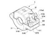
図2、10に示すように、第1分割片51の一端に設けた第1ヒンジ部513と、第2分割片52の一端に設けた第2ヒンジ部525は、支軸53を介して回動可能に係合されている。
第1分割片51の他端は、環状シール部材4の軸方向両側から一対の第1延設部514A、514Bが径方向外向きに延設されている。その一対の第1延設部514A、514Bの先端を繋ぐ第1延設部接合部517が形成されている。第1延設部514A、514Bには、第1延設部514から第2分割片52方向へ直立した一対の第1係止部519A、519Bがそれぞれ弾性変形可能に突設され形成されている。第1係止部519A、519Bの先端には、外向きに第1段差部519aA、519aBが形成されている。
第2分割片52の他端は、環状シール部材4の軸方向中央から一本の第2延設部526が外向きに延設されている。第2延設部526の先端は、T字形状に環状シール部材4の軸方向両側に広がって先端部530が形成されている。先端部530の内側には、第1係止部519A、519Bを弾性変形しながら係止する一対の第1係止受け部527A、527Bが設けられている。
図10に示すように、第1段差部519aA、519aBには、第1係止受け部527A、527Bと当接する第1係止部当接面519bA、519bBが設けられている。第1係止部当接面519bA、519bBは、その長手方向が環状シール部材4の軸方向と平行に配置している。第1係止受け部527A、527Bには、第1係止部519A、519Bと当接する第1係止受け部当接面527aA、527aBが設けられている。第1係止受け部当接面527aA、527aBは、その長手方向が環状シール部材4の軸方向と平行に設けられている。Next, the configuration in which the first and second divided
As shown in FIGS. 2 and 10, the
At the other end of the first divided
At the other end of the second divided
As shown in FIG. 10, first stepped portions 519aA and 519aB are provided with first locking portion contact surfaces 519bA and 519bB that come into contact with the first
第1係止部519A、519Bは、全長が第2延設部526の肉厚寸法より長くされている。これにより、連結部材5を第1及び第2接続部21、31の接続部分に装着した通常使用状態では、第1係止部519A、519Bが第1係止受け部527A、527Bに係止されて第1及び第2延設部514、526の間に図2に示す隙間S1を形成するようにしている。ここで、この隙間S1が形成された連結部材5の通常使用状態を、第1係止位置という。隙間S1がない図11に示す連結部材5の状態を、第2係止位置という。第1係止位置にあるときよりも、第2係止位置にあるときの方が、連結部材5は環状シール部材4方向に近づく。これにより増し締め状態となる。第1係止位置にあるときの第2係止部528A、528Bは、図5に示すように、第1延設部514A、514B及び第1延設部接合部517が取り囲む挿通孔529の内側に配置されている。 The
図5に示すように、第2分割片52の第2延設部526には、環状シール部材4の軸方向両側に一対の第2係止部528A、528Bが設けられている。第2係止部528A、528Bは、全長が第1延設部514の肉厚寸法より長くされている。第2係止部528A、528Bの先端には、環状シール部材4の軸方向外向きに第2段差部528aA、528aBが形成されている。
第1分割片51の第1延設部514A、514Bの第1係止部519が設けられた面の背向面であって内側には、第2係止部528A、528Bを弾性変形しながら係止する一対の第2係止受け部515A、515Bが設けられている。
第2係止部528と第2係止受け部515が当接した状態では、図14に示すように、第2段差部528aA、528aBに、第2係止受け部515A、515Bと当接する第2係止部当接面528bA、528bBが設けられ、第2係止受け部515A、518Bに、第2段差部528aA、528aBと当接する第2係止受け部当接面515aA、515aBが設けられている。第2係止部当接面528bA、528bBは、第2係止部528A、528Bの弾性変形による移動方向に対し、その先端側が、第2係止部528A、528Bの基部側に接近した面を有する。第2係止受け部当接面515aA、515aBは、当接の際、第2係止部当接面528bA、528bBに平行となる面を備えている。また、第2係止受け部当接面515aA、515aBと第2係止部当接面528bA、528bBは、その長手方向が環状シール部材4との軸方向と直交する方向に設けられている。As shown in FIG. 5, the second extending
While the
When the
(流体機器接続構造の作用)
はじめに、流体機器接続構造1の通常使用状態について図1から図9を用いて説明する。通常使用状態とは、第1及び第2流体機器2、3を、環状シール部材4を介して接続したあと、連結部材5を第1係止位置に設置した状態をいう。第1係止位置では、第1分割片51の第1係止部519が第2分割片52の第1係止受け部527に係合されている。
通常使用状態では、図6に示すように、連結部材5は、第1係止部519が第1係止受け部527に係止されており、第1及び第2延設部514、526の間には、図2に示すように隙間S1が形成される。連結部材5の内側は、図3に示すように、第1及び第2分割片51、52の第1及び第2突部511、521の突出方向先端と、装着溝23、33の底部との間の隙間Xがある。また、連結部材5の内周面と第1及び第2接続部31の外周面との間にも、隙間Xと同程度の隙間Yがある。(Function of fluid device connection structure)
First, a normal use state of the fluid device connection structure 1 will be described with reference to FIGS. 1 to 9. The normal use state is a state in which the first and
In the normal use state, as shown in FIG. 6, in the connecting
ここで、第1係止部519が第1係止受け部527と係止されたとき、第1係止部519のスナップの動きにより音が発生し、作業者に作業完了を知らせる。第2係止部528は、挿通孔529の内側に配置されており、外部から見えないため、作業者が第2係止部528を係合させようとすることはない。
第1実施形態では、環状シール部材4の両側に形成された環状シール溝46、47へ第1及び第2接続部21、31の圧入部24、34を圧入する作業を、事前に治具を使って実施し、連結部材5はその圧入状態を維持するために取り付けられる。通常使用状態においては、図3に示すように第1分割片51と第2分割片52が所定長さ近づけられており、環状シール部材4の両側に形成された環状シール溝46、47に第1及び第2接続部21、31の圧入部24、34が適切な位置で維持されているため、環状シール部材4のシール性能が十分な状態となる。Here, when the
In the first embodiment, the work of press-fitting the press-fitting
次に、流体機器接続構造1の増し締め状態について図11から図18を用いて説明する。
ここで、第1及び第2接続部21、31に高温の薬液と低温の純水を交互に流すと、第1及び第2接続部21、31がクリープ変形し、シール力が低下することがある。シール力が低下すると、液漏れが生じる。このような緊急時に、増し締めが行われる。増し締めが行われるとき、第1延設部接合部517と第2延設部526をつまんで第1分割片51と第2分割片52を近づけ、連結部材5を第2係止位置の状態にする。第1延設部接合部517と第2延設部526のつまみ部の平面が大きいので、工具等を用いて挟んだときに力が入りやすく、作業性が良い。増し締め状態では、第2分割片52の第2係止部528が第1分割片51の第2係止受け部515に係合する。これにより、第1及び第2延設部514、526の間の隙間S1はなくなる。Next, the retightening state of the fluid device connection structure 1 will be described with reference to FIGS. 11 to 18.
Here, when high-temperature chemical liquid and low-temperature pure water are alternately flown through the first and second connecting
連結部材5の内側は、第1分割片51と第2分割片52とが通常使用状態と比較してより近づけられるため、図4に示す接続側テーパ面26と連結側テーパ面523、接続側テーパ面36と連結側テーパ面524のテーパの作用力により、第1及び第2接続部21、31が近づけられ、環状シール部材4にフランジ部25とフランジ部35が押し付けられるため、シール力が強化される。図12に示すように、第1及び第2分割片51、52の第1及び第2突部511、521の突出方向先端と、装着溝23、33の底部との間の隙間Xは減少する。また、連結部材5の内周面と環状シール部材4の外周面との間の隙間Yは減少する。
さらに、第2係止位置では、環状シール部材4から反発力で第1及び第2分割片51、52を開こうとする際、第2係止部当接面528bA、528bBと第2係止受け部当接面515aA、515aBが当接すると、その面の傾き(かえり)により、当接面間の食付きが強まり、係止外れを防止している。
意図せず第1係止部519に触れてしまい、一方の第1係止部519Aが外れた場合にも、他方の第1係止部519Bにより連結部材5が外れることを防ぐことができる。また、第2係止部528も対になっているため、意図せず第2係止部528に触れてしまい、一方の第2係止部528Aが外れた場合にも、他方の第2係止部528Bにより連結部材5が外れることを防ぐことができる。On the inside of the connecting
Further, at the second locking position, when the first and second divided
Even if the first engaging
以上、説明したように、第1実施形態の流体機器接続構造1によれば、
(1)第1接続部21を有する第1流体機器2と、第2接続部31を有する第2流体機器3と、第1接続部21及び第2接続部31を接続する環状シール部材4と、第1接続部21及び第2接続部31の接続状態を維持する連結部材5と、を有し、連結部材5は、第1分割片51と第2分割片52を備え、第1分割片51と第2分割片52の一端に回動可能な連結部を設けた流体機器接続構造1において、第1分割片51は、第1係止部519を備え、第2分割片52は、第1係止部519が係止する第1係止受け部527を備え、連結部材5は、第1係止部519と第1係止受け部527が係合する第1係止位置を備えること、第2分割片52は、第2係止部528を備え、第1分割片51は、第2係止部528が係止する第2係止受け部515を備え、連結部材5は、第2係止部528と第2係止受け部515が係合する第2係止位置を備えること、連結部材5は、第1係止位置にあるときよりも、第2係止位置にあるときの方が、環状シール部材4方向に近づいていることを特徴とするので、増し締め用の第2係止部528は、その弾性変形により第2係止受け部515に係止されるため、一般的な工具を使って連結部材5を第1係止位置から第2係止位置に移動するだけで増し締めと保持まで完了する。第2係止位置に保持するための部材を必要とせず、早急な対応ができ、ボルト締付けなどの締めすぎによる部材変形する恐れがない。また、特別な治具を必要としないため、緊急時に早急な対応ができる。
さらに、第1係止部519と第2係止部528が独立して設けられているため、確実に引っ掛け部の強度を保つことが出来る。万が一、どちらかが破損しても、もう一方の係止部で締め付けを保持することができる。
(2)(1)に記載の流体機器接続構造1において、第1係止位置にあるとき、第2係止部528の先端にある第2段差部528aは、環状シール部材4の軸方向と直交する方向から目視できない位置にあることを特徴とするので、第1係止位置のところで第1係止部519の係止めが完了したとき、第2係止部528は、第1分割片51の挿通孔529の内側に位置し、外観からは見えにくい状態であるため、通常使用時に誤って第2係止位置まで締め付けてしまうことを防ぐことができる。As described above, according to the fluid device connection structure 1 of the first embodiment,
(1) A
Furthermore, since the
(2) In the fluid device connection structure 1 according to (1), when in the first locking position, the second step portion 528a at the tip of the
(3)(1)または(2)に記載の流体機器接続構造1において、第2係止部528の第2係止部当接面528bと第2係止受け部515の第2受け部当接面515aは、傾きが設けられていること、を特徴とするので、第2係止部528と第2係止受け部515はその角度により連結部材5が開こうとする力が働くとさらに強く係合しあう方向に力が働く。増し締め状態を維持する第2係止位置では、環状シール部材4の反発力により第1及び第2接続部21、31同士が互いに離れる方向へ移動しようとするため、このことが有効に働く。第2係止部当接面528bA、528bBと第2係止受け部当接面515aA、515aBが当接するとその面の傾き(かえり)により、増し締めにより発生した環状シール部材4からの反発力があっても、第2係止位置が外れることを防ぐことができる。
(4)(1)乃至(3)のいずれか一つに記載の流体機器接続構造1において、第1係止部519と第2係止部528のうち少なくとも一方は対に設けられていること、を特徴とするので、意図せず第1係止部519に触れてしまい、一方の第1係止部519Aが外れた場合にも、他方の第1係止部519Bにより連結部材5が外れることを防ぐことができる。第2係止部528も対になっているため、意図せず第2係止部528に触れてしまい、一方の第2係止部528Aが外れた場合にも、他方の第2係止部528Bにより連結部材5が外れることを防ぐことができる。
(5)(1)乃至(3)のいずれか一つに記載の流体機器接続構造1において、第1係止部519の第1係止部当接面519bA、519bBと第2係止部528の第2係止部当接面528bA、528bBは、互いに直交する関係にあること、を特徴とするので、第1係止部519の当接面の長手方向を環状シール部材4の軸方向と平行に設け、第2係止部528の当接面の長手方向を環状シール部材4の軸方向と直交に設けることで、第1係止部519と第2係止部528をコンパクトに配置でき、連結部材5自体をコンパクトにすることができる。(3) In the fluid device connection structure 1 according to (1) or (2), the second locking portion contact surface 528b of the
(4) In the fluid device connection structure 1 according to any one of (1) to (3), at least one of the
(5) In the fluid device connection structure 1 according to any one of (1) to (3), the first locking portion contact surfaces 519bA, 519bB and the
上記実施形態を以下のように変形して実施することもできる。
環状シール部材4の両側に形成された環状シール溝46、47へ、第1及び第2接続部21、31の圧入部24、34を圧入する作業は、別途治具を使って実施することに限らず、第1及び第2接続部21、31へ連結部材5を装着する際、互いの口元テーパ形状の摺接により圧入作業を同時実施することもできる。
また、第2係止部528の第2係止部当接面528bの傾き(かえり)を第1段差部519aに設けることもできる。
さらに、第1及び第2係止部519、528の第1係止部当接面519b、第2係止部当接面528bは、いずれも環状シール部材4の半径方向に合わせることができる。The above embodiment may be modified as follows.
The work of press-fitting the press-fitting
Further, the inclination (burr) of the second engaging portion contact surface 528b of the second
Furthermore, both the first locking
<第2実施形態>
次に、本発明の流体機器接続構造の第2実施形態について説明する。
第2実施形態の流体機器接続構造1は、連結部材6を除き、第1実施形態の流体機器接続構造1と構成が同じである。ここでは、第1実施形態と異なる点を中心に説明し、第1実施形態と共通する点は第1実施形態と同じ番号を付することで適宜説明を省略する。
図20は、第2実施形態の流体機器接続構造1の連結部材6が第1係止位置にあるときの平面図である。図21は、図20のHH断面図で、図22は、図20のJJ断面図である。図23は、連結部材6が第1係止位置にあるときの正面図で、図24は、その右側面図、図25は、その斜視図である。図26は、連結部材6が第2係止位置にあるときの正面図で、図27は、図26のKK断面図、図28は、図26のLL断面図である。図29は、連結部材6が第2係止位置にあるときの正面図で、図30は、その右側面図、図31は、その斜視図である。<Second Embodiment>
Next, a second embodiment of the fluid device connection structure of the present invention will be described.
The fluid device connection structure 1 of the second embodiment has the same configuration as the fluid device connection structure 1 of the first embodiment except for the connecting
FIG. 20 is a plan view when the connecting
連結部材6は、図21に示すように、第1分割片61と第2分割片62を有する。第1分割片61の一端は回動可能に係合され、第1分割片61の他端は、底面を有する空洞の第1延設部614が径方向外向きに延設されている。第1延設部614の内側底面から、板状の第1係止部618が弾性変形可能に突設され形成されている。第2係止部619の先端には、径方向内向きに一対の第2段差部619aが形成されている。第2係止部619には、さらに外側に向かって第1係止部618が弾性変形可能に突設され形成されている。第1係止部618の先端には、環状シール部材4の軸方向外向きに第1段差部618aが形成されている。
第2分割片62の他端は、中空状の第2延設部624が径方向外向きに延設されている。第2延設部624には、挿通孔629が貫いて形成されている。第2分割片62の先端の外周には、第2係止部619と係合する第2係止受け部626が径方向外側に向かって形成されている。第2延設部624の内側上面には、図22に示すように、第1係止部618と係合する第1係止受け部627A、627Bが形成されている。
通常使用状態では、連結部材6は、第1係止部618が第1係止受け部627に係止されており、図21に示すように、第1及び第2延設部614、624の間に隙間S2が形成され、連結部材6は第1係止位置にある。次に、増し締め状態は、シール力が低下して、液漏れが生じると、緊急対応としてとる状態で、連結部材6は第2係止位置にある。このとき、第1分割片61の第2係止部619が第2分割片62の第2係止受け部626に係合する。これにより、第1及び第2延設部614、624の間の隙間S2はなくなる。As shown in FIG. 21, the connecting
At the other end of the second divided
In the normal use state, in the connecting
以上、説明したように、第2実施形態の流体機器接続構造1によれば、
第1係止位置にあるとき、第2係止部619の先端にある第2段差部619aは、環状シール部材4の軸方向と直交する方向から目視できない位置にあること、を特徴とするので、第2係止部619は、第1係止位置のところで係止めが完了したときには、まだ第1分割片61の第2係止部619部が通過する挿通孔629の内側に在り外観からは見えないため、そこに第2係止部619があることは認識できない。さらに、第2係止受け部626についても、挿通孔629の内側に配置されているため、この位置に第2係止位置が在ることをさらに認識できないため、通常使用時に誤って第2係止位置まで締め付けてしまうことを、さらに抑制することができる。
その他の効果については第1実施形態と同じである。As described above, according to the fluid device connection structure 1 of the second embodiment,
When in the first locking position, the second stepped
Other effects are the same as those in the first embodiment.
<第3実施形態>
次に、本発明の流体機器接続構造の第3実施形態について説明する。
第3実施形態の流体機器接続構造1は、連結部材7を除き、第1実施形態の流体機器接続構造1と構成が同じである。ここでは、第1実施形態と異なる点を中心に説明し、第1実施形態と共通する点は第1実施形態と同じ番号を付することで適宜説明を省略する。
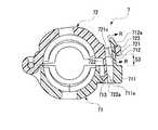
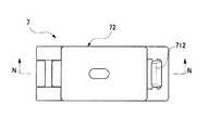
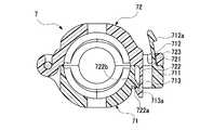
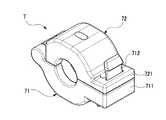
図32は、連結部材7が第1係止位置にあるときの平面図で、図33は、図32のMM断面図である。図34は、図33のRR断面図である。図35は、連結部材7が第1係止位置にあるときの正面図で、図36は、その右側面図、図37は、その斜視図である。図38は、連結部材7が第2係止位置にあるときの平面図で、図39は、図38のNN断面図である。図40は、連結部材7が第2係止位置にあるときの正面図で、図41は、その右側面図、図42は、その斜視図である。<Third Embodiment>
Next, a third embodiment of the fluid device connection structure of the present invention will be described.
The fluid device connection structure 1 of the third embodiment is the same as the fluid device connection structure 1 of the first embodiment except for the connecting
32 is a plan view when the connecting
連結部材7は、図37に示すように、第1分割片71と第2分割片72を有する。第1分割片71の一端は回動可能に係合され、第1分割片71の他端は、中空状の第1延設部711が径方向外向きに延設されている。第1延設部711には、挿通孔711aが貫いて形成されている。図33に示すように、第1延設部711の外側上面から、板状の第1係止部712が第2分割片72に向かって弾性変形可能に突設され形成されている。第1係止部712の先端には、径方向外向きに第1段差部712aが形成されている。挿通孔711aの径方向内側には、後述する第2係止部722と係合する第2係止受け部713が形成されている。
第2分割片72の他端は、中空状の第2延設部721が径方向外向きに延設されている。第2延設部721には挿通孔721cが貫いて形成されている。第2延設部721の径方向内側には、第1分割片71の第1延設部711に向かって第2係止部722が弾性変形可能に突設され形成されている。第2係止部722の先端には、径方向内向きに第2段差部722aが形成されている。第2延設部721の外側上面には、第1係止部712と係合する第1係止受け部723が形成されている。As shown in FIG. 37, the connecting
At the other end of the second divided
図34に示すように、第1段差部712aの環状シール部材4の軸方向両端には、先細りのテーパ712bA、712bBが設けられている。第2延設部721の挿通孔721cの環状シール部材4の軸方向両側面には、円周方向にボス721aA、721aBが突出して設けられている。ボス721aA、721aBの第1分割片71側にテーパ721bA、721bBが設けられている。第1係止部712が、第2延設部721の挿通孔721c内を第1分割片71側から通過する際、第1段差部712aのテーパ712bA、712bBが、両側のボス721aA、721aBのテーパ721bA、721bBを環状シール部材4の軸方向に押し広げながら比較的小さな推進力を加えるだけで進む。これにより、第1段差部712aが第1係止受け部723の位置を通過すると、第1係止部712の弾性力により第1係止受け部723側に倒れこみ、当接する。同時に、第1係止部712が両側のボス721aA、721aBから第1係止受け部723側に脱落し係止が完了する。
第1係止位置から第1係止部712を外すためには、挿入時のテーパを利用することができないため、ボス721aA、721aBを押し広げるための比較的大きな力が必要となる。そのため、第1係止部712は容易に外れることは無く、誤操作外れ防止とすることができる。As shown in FIG. 34, tapered tapers 712bA and 712bB are provided at both axial ends of the
In order to disengage the
通常使用状態では、連結部材7は、第1係止部712が第1係止受け部723に係止されており、図33に示すように、第1及び第2延設部711、721の間に隙間S3が形成され、連結部材7は第1係止位置にある。次に、増し締め状態は、シール力が低下して、液漏れが生じると、緊急対応としてとる状態で、連結部材7は第2係止位置にある。このとき、第2分割片72の第2係止部722が第1分割片71の第2係止受け部713に係合する。これにより、第1及び第2延設部711、721の間の隙間S3はなくなる。 In the normal use state, in the connecting
以上、説明したように、第3実施形態の流体機器接続構造1によれば、
第2分割片72に設けられた挿通孔721cを第1係止部712が通過する際、挿通孔721cが広がり、第1係止部712が通過後に挿通孔721cは元の形状に戻ること、を特徴とするので、第1係止部712を外すためには、挿入時のテーパ712bA、712bBを利用することができず、挿通孔721cを押し広げるための比較的大きな力が必要となる。そのため、第1係止部712は容易に外れることはなく、誤操作外れを防止することができる。第1係止位置の外れ止めを適切なボスの配置によりを設けたため、連結部材7の構造をシンプルにでき、コンパクトにできる。
その他の効果については第1実施例と同じである。As described above, according to the fluid device connection structure 1 of the third embodiment,
When the
Other effects are the same as those in the first embodiment.
<第1参考形態>
次に、本発明の流体機器接続構造の第1参考形態について説明する。
第2実施形態の流体機器接続構造1は、連結部材8を除き、第1実施形態の流体機器接続構造1と構成が同じである。ここでは、第1実施形態と異なる点を中心に説明し、第1実施形態と共通する点は第1実施形態と同じ番号を付することで適宜説明を省略する。
図43は、参考例の流体機器接続構造の連結部材8が第1係止位置にあるときの平面図である。図44は、図43のPP断面図である。図45は、連結部材8が第1係止位置にあるときの平面図で、図46は、その右側面図、図47は、その斜視図である。図48は、連結部材8が第2係止位置にあるときの断面図である。<First Reference Form>
Next, a first reference embodiment of the fluid device connection structure of the present invention will be described.
The fluid device connection structure 1 of the second embodiment has the same configuration as the fluid device connection structure 1 of the first embodiment except for the connecting
FIG. 43 is a plan view when the connecting
連結部材8は、図44に示すように、第1分割片81と第2分割片82を有する。第1分割片81の一端は回動可能に係合され、第1分割片81の他端は、環状シール部材4の軸方向中央に第1延設部811が環状シール部材4の径方向外向きに延設されている。第2分割片82の他端は、一対の第2延設部821A、821Bが環状シール部材4の径方向外向きに延設されている。第1延設部811から第2延設部821に向かって、板状の第1係止部812が弾性変形可能に突設され形成されている。第1係止部812の先端には、環状シール部材4の径方向内向きに第1段差部812aが形成されている。第1延設部811の径方向外側の面には、位置決め手段である凹部811aが形成されている。
第2分割片82の環状シール部材4の軸方向中央には、図44に示すように、第1係止部812と係止する第1係止受け部822が形成されている。第2延設部821A、821Bには、位置決め手段である凹部821aA、821aBが形成されている。図48に示すように、棒状のピン部材10を凹部811aと凹部821aA、821aBに嵌めることができる。As shown in FIG. 44, the connecting
As shown in FIG. 44, a first
通常使用状態では、連結部材8は、第1係止部812が第1係止受け部822に係止されており、図44に示すように、第1及び第2延設部811、821の間に隙間S4が形成され、連結部材8は第1係止位置にある。
図46に示すように、第1段差部812aの環状シール部材4の軸方向先端側面には先細りのテーパ812bA、812bBが設けられている。第2延設部821に囲まれる凹部の環状シール部材4の軸方向両側面には、ボス821bA、821bBが設けられている。ボス821bA、821bBの第1分割片81側にテーパ821cA、821cBが設けられている。第1係止部812が、第2延設部821の凹部を第1分割片81側から通過する際、第1段差部812aのテーパ812bA、812bBが、両側のボス821bA、821bBのテーパ821cA、821cBを環状シール部材4の軸方向に押し広げながら比較的小さな推進力を加えるだけで進む。第1段差部812aが第1係止受け部822の位置を通過すると、第1係止部812自身の弾性力により第1係止受け部822側に倒れこみ、当接する。同時に、第1係止部812が両側のボス821bA、821bBから第1係止受け部822側に脱落し係止が完了する。
第1係止位置から第1係止部812を外すためには、挿入時のテーパを利用することができず、ボス821bA、821bBを押し広げるための比較的大きな力が必要となる。そのため、容易に外れることは無く、誤操作外れ防止することができる。
次に、増し締め状態は、シール力が低下して、液漏れが生じると、緊急対応としてとる状態で、連結部材8は第2係止位置にある。このとき、図48に示すように、ピン部材10を凹部811aと凹部821aA、821aBに嵌めることにより第1及び第2延設部811、821を近づけることができる。これにより、第1及び第2延設部811、821の間の隙間S4はなくなる。In the normal use state, in the connecting
As shown in FIG. 46, tapered tapers 812bA and 812bB are provided on the axial end surface of the
In order to disengage the
Next, in the retightened state, when the sealing force is reduced and liquid leakage occurs, the
<第2参考形態>
次に、本発明の流体機器接続構造の第2参考形態について説明する。
図49の流体機器接続構造1は、連結部材9を除き、第1実施形態の流体機器接続構造1と構成が同じである。ここでは、第1実施形態と異なる点を中心に説明する。
連結部材9は、増し締め用の係止部やテーパ、作業性を考慮したヒンジ部を排除することで省スペース化に特化した連結部材である。
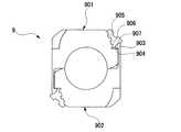
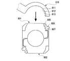
図49は、流体機器接続構造1の連結部材9が締付け状態にあるときの斜視図である。図50は、図49の正面図である。図51は、図50の右側面図である。なお、左側面図は、右側面図と対称であるため、省略する。図52から図54は、治具を用いて連結部材9の係止を解除するときの正面図である。図55は、第2参考形態の流体機器接続構造の連結部材がバルブ等の制御機器の面間にある図である。図56は、図55の平面図である。
連結部材9は、図49に示すように、第1分割片901と第2分割片902を有する。第1分割片901と第2分割片902は同一形状の部材であるため、第1分割片901の説明をすることで、第2分割片902の説明を省略する。
第1分割片901には、図50に示すように、第1係止部903と第1係止受け部904が形成されている。第1分割片901には、連結部材9を取り外す時に治具910の工具を使用できるように第1凹部905、第2凹部906、第3凹部907が形成されている。治具910は、図52に示すように、半月形状であり、その先端の内周面には、連結部材9を取り外す際に第1分割片901の第1凹部905、第2凹部906、第3凹部907に引掛けるための第1突起911、第2突起912、第3突起913が形成されている。
治具910の第3突起913を第3凹部907に挿入する際、図53に示すように、第1係止部903は、連結部材9の円周方向外側(図中矢印T方向)に弾性変形する。これにより、第1係止部903と第1係止受け部904の係止は解除される。次に、図54に示すように、治具910と係合された第1分割片901を矢印U方向に回転させると、第2分割片902から取り外すことができる。
本形態の連結部材9を用いることで、図55、56に示すように、バルブ等の制御機器の面間の範囲内で連結部材9を収めることが可能である。<Second reference form>
Next, a second reference embodiment of the fluid device connection structure of the present invention will be described.
The fluid device connection structure 1 of FIG. 49 has the same configuration as the fluid device connection structure 1 of the first embodiment except for the connecting
The connecting
FIG. 49 is a perspective view when the connecting
As shown in FIG. 49, the connecting
As shown in FIG. 50, the
When the
By using the connecting
なお、本実施形態は単なる例示にすぎず、本発明を何ら限定するものではない。したがって本発明は当然に、その要旨を逸脱しない範囲内で様々な改良、変形が可能である。 Note that the present embodiment is merely an example and does not limit the present invention. Therefore, the present invention is naturally capable of various improvements and modifications without departing from the scope of the invention.
1 流体機器接続構造
2 第1流体機器
3 第2流体機器
4 環状シール部材
5 連結部材
21 第1接続部
31 第2接続部
51 第1分割片
52 第2分割片
515 第1係止受け部
519 第1係止部
527 第1係止受け部
528 第2係止部DESCRIPTION OF SYMBOLS 1 Fluid
Claims (6)
Translated fromJapanese前記連結部材は、第1分割片と第2分割片を備え、前記第1分割片と前記第2分割片の一端に回動可能な連結部を設けた流体機器接続構造において、
前記第1分割片は、第1係止部を備え、前記第2分割片は、前記第1係止部が係止する第1係止受け部を備え、前記連結部材は、前記第1係止部と前記第1係止受け部が係合する第1係止位置を備えること、
前記第1分割片または前記第2分割片の一方は、第2係止部を備え、前記第1分割片または第2分割片の他方は、前記第2係止部が係止する第2係止受け部を備え、前記連結部材は、前記第2係止部と前記第2係止受け部が係合する第2係止位置を備えること、
前記連結部材は、前記第1係止位置にあるときよりも、前記第2係止位置にあるときの方が、前記環状シール部材方向に近づいていること、
前記連結部材が前記第1係止位置にあるときは、前記第1係止部と前記第1係止受け部のみが係合しており、前記連結部材が前記第2係止位置にあるときは、前記第2係止部と前記第2係止受け部のみが係合していること、
を特徴とする流体機器接続構造。A first fluid device having a first connection portion, a second fluid device having a second connection portion, an annular seal member that connects the first connection portion and the second connection portion, the first connection portion and the A connecting member that maintains the connection state of the second connecting portion,
In the fluid device connection structure, the connecting member includes a first divided piece and a second divided piece, and a rotatable connecting portion is provided at one end of the first divided piece and the second divided piece,
The first split piece includes a first locking portion, the second split piece includes a first locking receiving portion that is locked by the first locking portion, and the connecting member includes the first engaging member. A first locking position at which the locking portion and the first locking receiving portion engage with each other;
One of the first divided piece or the second divided piece includes a second locking portion, and the other of the first divided piece or the second divided piece is a second engagement member with which the second locking portion is locked. A stop receiving portion, and the connecting member includes a second locking position where the second locking portion and the second locking receiving portion are engaged with each other,
The connecting member is closer to the annular seal member when in the second locking position than in the first locking position,
When the connecting member is in the first locking position, only the first locking portion and the first locking receiving portion are engaged, and the connecting member is in the second locking position. Means that only the second locking portion and the second locking receiving portion are engaged,
A fluid device connection structure characterized by:
前記第1係止位置にあるとき、前記第2係止部の先端にある第2段差部は、前記環状シール部材の軸方向と直交する方向から目視できない位置にあること、
を特徴とする流体機器接続構造。The fluid device connection structure according to claim 1,
When in the first locking position, the second step portion at the tip of the second locking portion is in a position invisible from the direction orthogonal to the axial direction of the annular seal member,
A fluid device connection structure characterized by:
前記第2係止部と前記第2係止受け部の当接面は、傾きが設けられていること、
を特徴とする流体機器接続構造。The fluid device connection structure according to claim 1 or 2,
The contact surface between the second locking portion and the second locking receiving portion is provided with an inclination,
A fluid device connection structure characterized by:
前記第1係止部と前記第2係止部のうち少なくとも一方は対に設けられていること、
を特徴とする流体機器接続構造。The fluid device connection structure according to any one of claims 1 to 3,
At least one of the first locking portion and the second locking portion is provided in a pair,
A fluid device connection structure characterized by:
前記第1係止部の当接面と前記第2係止部の当接面は、互いに直交する関係にあること、
を特徴とする流体機器接続構造。The fluid device connection structure according to any one of claims 1 to 3,
The contact surface of the first locking portion and the contact surface of the second locking portion are orthogonal to each other,
A fluid device connection structure characterized by:
前記第1分割片または前記第2分割片に設けられた挿通孔を前記第1係止部が通過する際、前記挿通孔が広がり、前記第1係止部が通過後に前記挿通孔は元の形状に戻ること、
を特徴とする流体機器接続構造。The fluid device connection structure according to any one of claims 1 to 3,
When the first locking portion passes through the insertion hole provided in the first divided piece or the second divided piece, the insertion hole expands, and the insertion hole returns to the original state after the first locking portion has passed. Returning to shape,
A fluid device connection structure characterized by:
Priority Applications (1)
| Application Number | Priority Date | Filing Date | Title |
|---|---|---|---|
| JP2016129730AJP6695222B2 (en) | 2016-06-30 | 2016-06-30 | Fluid equipment connection structure |
Applications Claiming Priority (1)
| Application Number | Priority Date | Filing Date | Title |
|---|---|---|---|
| JP2016129730AJP6695222B2 (en) | 2016-06-30 | 2016-06-30 | Fluid equipment connection structure |
Related Parent Applications (1)
| Application Number | Title | Priority Date | Filing Date |
|---|---|---|---|
| JP2016059937Division | 2016-03-24 | 2016-03-24 |
Publications (2)
| Publication Number | Publication Date |
|---|---|
| JP2017172785A JP2017172785A (en) | 2017-09-28 |
| JP6695222B2true JP6695222B2 (en) | 2020-05-20 |
Family
ID=59972566
Family Applications (1)
| Application Number | Title | Priority Date | Filing Date |
|---|---|---|---|
| JP2016129730AActiveJP6695222B2 (en) | 2016-06-30 | 2016-06-30 | Fluid equipment connection structure |
Country Status (1)
| Country | Link |
|---|---|
| JP (1) | JP6695222B2 (en) |
Families Citing this family (3)
| Publication number | Priority date | Publication date | Assignee | Title |
|---|---|---|---|---|
| JP6903025B2 (en)* | 2018-03-22 | 2021-07-14 | 日本ピラー工業株式会社 | Fluid device |
| JP7372075B2 (en)* | 2019-08-07 | 2023-10-31 | 日本ピラー工業株式会社 | Connecting member |
| JP7457478B2 (en)* | 2019-09-26 | 2024-03-28 | 積水化学工業株式会社 | Resin pipe connection device |
Family Cites Families (7)
| Publication number | Priority date | Publication date | Assignee | Title |
|---|---|---|---|---|
| US4881760A (en)* | 1988-11-07 | 1989-11-21 | Stanley Aviation Corporation | Conduit coupling device with redundancy features |
| US5620210A (en)* | 1995-10-24 | 1997-04-15 | Stanley Aviation Corporation | Fluid conduit coupling |
| DE19650675C2 (en)* | 1996-12-06 | 2002-10-31 | Rasmussen Gmbh | profile clip |
| JP2003214583A (en)* | 2002-01-22 | 2003-07-30 | Zexel Valeo Climate Control Corp | Pipe joint structure, cover member and plug removing method |
| SE524585C2 (en)* | 2002-03-04 | 2004-08-31 | Aba Sweden Ab | Pipe coupling device comprising two articulated halves |
| JP4575973B2 (en)* | 2007-10-05 | 2010-11-04 | シーケーディ株式会社 | Fluid device connection structure and fluid device unit |
| JP5134573B2 (en)* | 2009-03-13 | 2013-01-30 | Ckd株式会社 | Fluid device connection structure and fluid device unit |
- 2016
- 2016-06-30JPJP2016129730Apatent/JP6695222B2/enactiveActive
Also Published As
| Publication number | Publication date |
|---|---|
| JP2017172785A (en) | 2017-09-28 |
Similar Documents
| Publication | Publication Date | Title |
|---|---|---|
| KR102262376B1 (en) | Connection seal structure and seal member | |
| US20200208594A1 (en) | Fluid connector with full insertion assurance cap disconnect tool | |
| KR200232262Y1 (en) | tube coupler | |
| JP6695222B2 (en) | Fluid equipment connection structure | |
| KR101695561B1 (en) | Connecting structure for connecting a pipe member to a target | |
| WO2014010235A1 (en) | Connector | |
| JP2009127809A (en) | Pipe joint part structure | |
| TWI537508B (en) | Quick release connector | |
| JP2019090503A (en) | Pipe joint | |
| JP2009079636A (en) | Swivel coupling | |
| JP2003176888A (en) | Plug-in type pipe fitting | |
| JP5417589B2 (en) | Pipe fitting | |
| JP4871749B2 (en) | Quick connector | |
| JP6171508B2 (en) | Pipe fitting | |
| JP4881753B2 (en) | Quick connector | |
| CN214618322U (en) | Connect buckle anti-disengaging structure soon | |
| WO2014010234A1 (en) | Connector | |
| JP7146885B2 (en) | Fittings and piping construction | |
| KR20230076491A (en) | socket joint for pipe connection | |
| JP2019039562A (en) | Connection part seal structure and seal member | |
| JP6284075B2 (en) | connector | |
| JP2019078387A (en) | Pipe joint | |
| JP3702671B2 (en) | Quick connector | |
| KR100446186B1 (en) | tube coupler | |
| JP4845511B2 (en) | Pipe fitting |
Legal Events
| Date | Code | Title | Description |
|---|---|---|---|
| A621 | Written request for application examination | Free format text:JAPANESE INTERMEDIATE CODE: A621 Effective date:20181205 | |
| A131 | Notification of reasons for refusal | Free format text:JAPANESE INTERMEDIATE CODE: A131 Effective date:20191015 | |
| A521 | Written amendment | Free format text:JAPANESE INTERMEDIATE CODE: A523 Effective date:20191205 | |
| TRDD | Decision of grant or rejection written | ||
| A01 | Written decision to grant a patent or to grant a registration (utility model) | Free format text:JAPANESE INTERMEDIATE CODE: A01 Effective date:20200331 | |
| A61 | First payment of annual fees (during grant procedure) | Free format text:JAPANESE INTERMEDIATE CODE: A61 Effective date:20200421 | |
| R150 | Certificate of patent or registration of utility model | Ref document number:6695222 Country of ref document:JP Free format text:JAPANESE INTERMEDIATE CODE: R150 |