JP6695113B2 - Furniture - Google Patents
FurnitureDownload PDFInfo
- Publication number
- JP6695113B2 JP6695113B2JP2015170868AJP2015170868AJP6695113B2JP 6695113 B2JP6695113 B2JP 6695113B2JP 2015170868 AJP2015170868 AJP 2015170868AJP 2015170868 AJP2015170868 AJP 2015170868AJP 6695113 B2JP6695113 B2JP 6695113B2
- Authority
- JP
- Japan
- Prior art keywords
- backrest
- main body
- seat
- advancing
- furniture
- Prior art date
- Legal status (The legal status is an assumption and is not a legal conclusion. Google has not performed a legal analysis and makes no representation as to the accuracy of the status listed.)
- Active
Links
- 238000005452bendingMethods0.000claimsdescription16
- 238000003780insertionMethods0.000claimsdescription8
- 230000037431insertionEffects0.000claimsdescription8
- 238000000926separation methodMethods0.000claimsdescription7
- 210000002414legAnatomy0.000description22
- 238000009434installationMethods0.000description20
- 239000011347resinSubstances0.000description17
- 229920005989resinPolymers0.000description17
- 239000002184metalSubstances0.000description8
- 238000000465mouldingMethods0.000description8
- 238000010586diagramMethods0.000description4
- 238000003466weldingMethods0.000description3
- JOYRKODLDBILNP-UHFFFAOYSA-NEthyl urethaneChemical compoundCCOC(N)=OJOYRKODLDBILNP-UHFFFAOYSA-N0.000description2
- 230000007423decreaseEffects0.000description2
- 210000001217buttockAnatomy0.000description1
- 230000006835compressionEffects0.000description1
- 238000007906compressionMethods0.000description1
- 230000000694effectsEffects0.000description1
- 230000005489elastic deformationEffects0.000description1
- 238000004519manufacturing processMethods0.000description1
- 239000000463materialSubstances0.000description1
- 230000013011matingEffects0.000description1
- 239000007769metal materialSubstances0.000description1
- 230000000149penetrating effectEffects0.000description1
- 230000002093peripheral effectEffects0.000description1
- 125000006850spacer groupChemical group0.000description1
Images


Classifications
- A—HUMAN NECESSITIES
- A47—FURNITURE; DOMESTIC ARTICLES OR APPLIANCES; COFFEE MILLS; SPICE MILLS; SUCTION CLEANERS IN GENERAL
- A47C—CHAIRS; SOFAS; BEDS
- A47C1/00—Chairs adapted for special purposes
- A47C1/02—Reclining or easy chairs
- A47C1/022—Reclining or easy chairs having independently-adjustable supporting parts
- A47C1/024—Reclining or easy chairs having independently-adjustable supporting parts the parts, being the back-rest, or the back-rest and seat unit, having adjustable and lockable inclination
- A47C1/0246—Reclining or easy chairs having independently-adjustable supporting parts the parts, being the back-rest, or the back-rest and seat unit, having adjustable and lockable inclination by means of screw-and-nut mechanism
- A—HUMAN NECESSITIES
- A47—FURNITURE; DOMESTIC ARTICLES OR APPLIANCES; COFFEE MILLS; SPICE MILLS; SUCTION CLEANERS IN GENERAL
- A47C—CHAIRS; SOFAS; BEDS
- A47C11/00—Benches not otherwise provided for
- A47C11/005—Benches not otherwise provided for having multiple separate seats
Landscapes
- Health & Medical Sciences (AREA)
- Dentistry (AREA)
- General Health & Medical Sciences (AREA)
- Chair Legs, Seat Parts, And Backrests (AREA)
- Chairs Characterized By Structure (AREA)
- Special Chairs (AREA)
Description
Translated fromJapanese本発明は、椅子等の什器に関するものである。 The present invention relates to furniture such as chairs.
公共施設の待合室等で用いられる椅子(什器)として、座を含む椅子本体部材(什器本体部材)の後部上面に、起立部材である背凭れが締結固定されたものが知られている(特許文献1参照)。 2. Description of the Related Art As a chair (furniture) used in a waiting room or the like of public facilities, there is known a chair body member (furniture body member) including a seat, to which a backrest, which is an upright member, is fastened and fixed (Patent Document 1).
特許文献1に記載の什器は、座と脚部を含む什器本体部材が略水平な支持杆に固定されるとともに、座の後部上面に背凭れが締結固定されている。背凭れは、座の下方から背凭れに挿通されたボルトの先端部が、背凭れ内に配置されたナットに螺合されることによって固定されている。背凭れは、ボルトの締め込みによって座に強く引き付けられることにより、座の後部に堅牢に締結される。また、背凭れの下面には凸部が設けられ、座の後部上面には、背凭れの凸部が嵌入される凹部が設けられている。座に対する背凭れの取付時には、背凭れ側の凸部が座側の凹部に嵌合されることによって背凭れと座の係合部の接触面積が大きく確保される。特許文献1に記載の什器は、これによって背凭れの支持強度の増大が図られている。 In the furniture described in
ところで、このような什器は、什器本体部材と起立部材の製造誤差や組付け誤差等によって什器本体部材に対する起立部材の設置角度にばらつきが生じることがある。この起立部材の設置角度のばらつきは、公共施設の待合室等で什器が複数並んで設置されるとき等に特に目立ち易い。 By the way, in such a furniture, the installation angle of the upright member with respect to the furniture main body member may vary due to a manufacturing error or an assembly error between the furniture main body member and the upright member. This variation in the installation angle of the upright members is particularly noticeable when a plurality of fixtures are installed side by side in a waiting room of a public facility.
そこで本発明は、什器本体部材に対する起立部材の設置角度を適切に調整することができる什器を提供しようとするものである。 Therefore, the present invention is intended to provide a fixture that can appropriately adjust the installation angle of the standing member with respect to the fixture main body member.
本発明に係る什器は、什器本体部材と、前記什器本体部材から上方に起立した状態で前記什器本体部材に対して連結され、前記什器本体部材の第1面に対向する第2面を有する起立部材と、前記什器本体部材の前記第1面と前記起立部材の前記第2面とを、複数箇所で連結する連結手段と、前記什器本体部材と前記起立部材の少なくともいずれか一方に設けられ、対向する前記第1面と前記第2面の間の一部の離間幅を調整する調整手段と、を備え、前記調整手段は、前記什器本体部材と前記起立部材の少なくともいずれか一方に進退位置調整可能に保持される進退部材を有し、前記連結手段は、前記進退部材の端面を前記第1面と前記第2面のいずれか一方に当接させることを特徴とする。
上記の構成により、什器本体部材に対する起立部材の設置角度を調整する場合には、調整手段によって対向した第1面と第2面の間の一部の離間幅を調整する。この状態において、第1面と第2面を連結手段によって連結する。これにより、什器本体部材に対する起立部材の設置角度は、調整手段の調整量に応じた角度に調整される。The fixture according to the present invention is a fixture main body member, and an upright having a second surface that is connected to the fixture main body member in a state of standing upright from the fixture main body member and that faces the first surface of the fixture main body member. A member, a connecting meansfor connecting the first surface of the furniture main body member and the second surface of the standing member at a plurality of locations, and provided on at least one of the furniture main body member and the standing member, Adjusting means for adjusting a separation width of a part between the first surface and the second surface facing each other,wherein the adjusting means moves the retracted position to at least one of the furniture main body member and the standing member. It has an advancing / retreating member that is held so that it can be adjusted, and the connecting means brings the end surface of the advancing / retreating member into contact with either the first surface or the second surface .
With the above configuration, when adjusting the installation angle of the standing member with respect to the furniture main body member, a part of the gap between the first surface and the second surface facing each other is adjusted by the adjusting means. In this state, the first surface and the second surface are connected by the connecting means. Thereby, the installation angle of the standing member with respect to the furniture main body member is adjusted to an angle according to the adjustment amount of the adjusting means.
前記調整手段は、ネジ機構を有している構成であっても良い。
この場合、ネジ機構を操作することにより、第1面と第2面の間の一部の離間幅を無段階に微調整することが可能になる。The adjusting means may have a screw mechanism.
In this case, by operating the screw mechanism, it becomes possible to finely adjust the separation width of a part between the first surface and the second surface in a stepless manner.
前記連結手段は、前記第1面と前記第2面とを、前記起立部材の厚み方向の一端部寄りとなる部分と、当該一端部寄りとなる部分よりも前記厚み方向の他端部寄りとなる部分とで連結するボルト及びナットを備えてなり、前記調整手段は、前記厚み方向の他端部寄りとなる部分において、前記什器本体部材と前記起立部材の少なくともいずれか一方に設けられている構成であっても良い。
上記の構成において、什器本体部材に対する起立部材の設置角度を調整する場合には、厚み方向の他端部寄りとなる部分のボルト及びナットによる締結を解除した状態で、調整手段によって第1面と第2面の間の一部の離間幅を調整する。この後、厚み方向の他端部寄りとなる部分をボルト及びナットによって締結すると、厚み方向の一端部寄りの当接部位を支点として起立部材の起立角度が変化する。
また、この構成の場合、厚み方向の一端部寄りとなる部分と、他端部寄り部分となる部分が、いずれもボルト及びナットによって連結されるため、全体の構成を簡素化することができる。The connecting means divides the first surface and the second surface into a portion closer to one end portion in the thickness direction of the standing member and a portion closer to the other end portion in the thickness direction than a portion closer to the one end portion. The adjusting means is provided on at least one of the furniture main body member and the standing member at a portion near the other end in the thickness direction. It may be configured.
In the above configuration, when adjusting the installation angle of the upright member with respect to the fixture main body member, the adjustment means is used to remove the first surface from the first surface in a state where the fastening by the bolt and the nut of the portion closer to the other end in the thickness direction is released. A part of the separation width between the second surfaces is adjusted. After that, when the portion closer to the other end in the thickness direction is fastened with a bolt and a nut, the standing angle of the standing member changes with the contact portion near the one end in the thickness direction as a fulcrum.
Further, in the case of this configuration, since the portion closer to one end portion in the thickness direction and the portion closer to the other end portion are connected by the bolt and the nut, the entire configuration can be simplified.
前記連結手段は、前記第1面と前記第2面とを、前記起立部材の厚み方向の一端部寄りとなる部分で相互に回動可能に連結する連結ピン及びピン嵌合部と、前記第1面と前記第2面とを、前記一端部寄りとなる部分よりも前記厚み方向の他端部寄りとなる部分で連結するボルト及びナットと、を備えてなり、前記調整手段は、前記厚み方向の他端部寄りとなる部分において、前記什器本体部材と前記起立部材の少なくともいずれか一方に設けられている構成であっても良い。
この構成において、什器本体部材に対する起立部材の設置角度を調整する場合には、厚み方向の他端部寄りとなる部分のボルト及びナットによる締結を解除した状態で、調整手段によって第1面と第2面の間の一部の離間幅を調整する。この後、厚み方向の他端部寄りとなる部分をボルト及びナットによって締結すると、連結ピンとピン嵌合部の嵌合部分を回動支点として、起立部材の起立角度が変化する。
また、この構成の場合、什器本体部材に対する起立部材の設置角度を変更するために、他端部寄りとなる部分をボルト及びナットによって締結したときに、連結ピンとピン嵌合部による嵌合部分を回動支点として起立部材の角度をスムーズに変化させることができる。したがって、この構成を採用することにより、起立部材の設置角度の調整を容易に行うことが可能になるとともに、起立部材や什器本体部材の一部に不要な応力が残留するのを抑制することができる。The connecting means connects the first surface and the second surface to each other so as to be rotatable relative to each other at a portion closer to one end in the thickness direction of the upright member, and the first and second fitting surfaces, A bolt and a nut for connecting the first surface and the second surface at a portion closer to the other end in the thickness direction than a portion closer to the one end, and the adjusting means include the thickness. A configuration may be provided in at least one of the furniture main body member and the standing member at a portion near the other end in the direction.
In this configuration, when adjusting the installation angle of the upright member with respect to the furniture main body member, the adjustment means is used to release the first surface and the first surface from the first surface with the bolts and nuts in the portion closer to the other end in the thickness direction released. A part of the separation width between the two surfaces is adjusted. After that, when the portion closer to the other end portion in the thickness direction is fastened with a bolt and a nut, the upright angle of the upright member changes with the fitting portion between the connecting pin and the pin fitting portion as a pivot.
Further, in the case of this configuration, in order to change the installation angle of the standing member with respect to the furniture main body member, when the portion near the other end is fastened with the bolt and the nut, the fitting portion by the connecting pin and the pin fitting portion is The angle of the upright member can be smoothly changed as a rotation fulcrum. Therefore, by adopting this configuration, it becomes possible to easily adjust the installation angle of the standing member, and it is possible to prevent unnecessary stress from remaining on a part of the standing member and the furniture main body member. it can.
前記進退部材は、前記ボルトの軸部が挿入される挿通孔を有している構成としても良い。
この場合、他端部寄りとなる部分のボルトとナットが締め込まれるときに、ボルトとナットによる締結力が調整手段の進退部材に効率良く伝達されるようになる。The advancing / retreating member may have an insertion hole into which the shaft portion of the bolt is inserted.
In this case, the fastening force of the bolt and the nut can be efficiently transmitted to the advancing / retreating member of the adjusting means when the bolt and the nut in the portion near the other end are tightened.
前記第1面と前記第2面の少なくとも一方は、前記他端部寄りとなる部分の前記ボルト及びナットによる締結に伴う面の撓み変形を許容する撓み許容部を備えている構成であっても良い。
この場合、他端部寄りとなる部分のボルトとナットが相互に締め込まれたときに、撓み許容部が撓み変形することにより、他端部寄りとなる部分の当接部位が広い面積で当接し易くなる。At least one of the first surface and the second surface may be provided with a bending allowance portion that allows the bending deformation of the surface of the portion closer to the other end portion due to the fastening with the bolt and the nut. good.
In this case, when the bolts and nuts of the portion near the other end are tightened together, the bending allowance portion deforms flexibly, so that the abutting portion of the portion near the other end has a large area. It will be easier to contact.
前記他端部寄りとなる部分に配置されている前記連結手段は、前記一端部寄りとなる部分に配置されている前記連結手段に対して、前記起立部材の幅方向に離間した位置に配置されており、前記撓み許容部は、前記一端部寄りとなる部分の前記連結手段の配置位置と、前記他端部寄りとなる部分の前記連結手段の配置位置の間に少なくとも設けられている構成であっても良い。
この場合、撓み許容部の撓み代を容易に大きく確保することが可能になり、他端部寄りとなる部分の当接部位が広い面積でより容易に当接し易くなる。The connecting means arranged at the portion closer to the other end is arranged at a position separated from the connecting means arranged at the portion closer to the one end in the width direction of the standing member. The bending allowance portion is provided at least between a position where the connecting means is arranged at a portion closer to the one end and a position where the connecting means is arranged at a portion closer to the other end. It may be.
In this case, the bending allowance of the bending allowance portion can be easily ensured to be large, and the abutting portion of the portion near the other end can easily come into contact with a large area.
前記第1面と前記第2面の連結部分の周囲は、前記第1面と前記第2面の対向する方向に弾性変形可能な弾性部材によって被覆されている構成としても良い。
この場合、第1面と第2面の連結部分の周囲が弾性部材によって被覆されているため、什器本体部材に対する起立部材の設置角度を調整した場合にも、弾性部材が第1面と第2面の連結部分の周囲で弾性変形して第1面と第2面の連結部分の周囲に隙間が生じなくなる。The periphery of the connecting portion between the first surface and the second surface may be covered with an elastic member that is elastically deformable in the direction in which the first surface and the second surface face each other.
In this case, since the periphery of the connecting portion of the first surface and the second surface is covered with the elastic member, even when the installation angle of the standing member with respect to the furniture main body member is adjusted, the elastic member is not connected to the first surface and the second surface. There is no gap around the connecting portion between the first surface and the second surface due to elastic deformation around the connecting portion between the surfaces.
本発明によれば、什器本体部材の第1面と起立部材の第2面の間の一部の離間幅を調整する調整手段を備えているため、什器本体部材に対する起立部材の設置角度を適切に調整することができる。 According to the present invention, since the adjusting means is provided for adjusting the separation width of a part between the first surface of the furniture main body member and the second surface of the upright member, the installation angle of the upright member with respect to the furniture main body member is appropriate. Can be adjusted to.
以下、本発明の実施形態を図面に基づいて説明する。
図1は、第1の実施形態に係る什器である椅子1の全体構成を示す図である。この椅子1は、公共施設の待合室等で用いられる椅子である。この椅子1は、同構造のものが、略水平に直線的に延出する断面矩形状の支持杆2に、横並びに並列に並んで支持固定されている。支持杆2は、長手方向の複数箇所に脚体3A,3B,3Cが取り付けられ、その脚体3A,3B,3Cを介してフロア上に設置されるようになっている。支持杆2は、複数の椅子1と着座者の荷重を支える関係上、剛性の高い金属材料によって形成されている。支持杆2には、各椅子1の両側に隣接して肘掛け4が取り付けられている。また、一部の隣接する椅子1の間には、脚体3Cに支持された物品載置台5が配置されている。Hereinafter, embodiments of the present invention will be described with reference to the drawings.
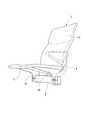
FIG. 1 is a diagram showing an overall configuration of a
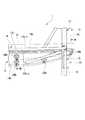
図2は、支持杆2に取り付けられた一つの椅子1を示す図であり、図3,図4は、椅子1の骨格部を示す図である。また、図5は、座11を裏面側から見た状態を示す図である。
椅子1は、着座者の臀部を支持する座11と、着座者の背部を支持する背凭れ12と、座11の左右の側縁部の下面から下方に延出して下端領域が支持杆2に固定される一対の連結脚13と、を備えている。この実施形態においては、座11と連結脚13とが什器本体部材を構成し、背凭れ12が起立部材を構成している。背凭れ12は、座11の後端部から上方に起立した状態において座11に連結されている。FIG. 2 is a view showing one
The
座11と連結脚13は、それぞれ骨格を成す金属製の座フレーム14と脚フレーム15を有している。脚フレーム15は、座フレーム14の左右両側の縁部に一体に結合されている。座フレーム14と左右の脚フレーム15とは、これらのほぼ全域が弾性を有する一体のモールド樹脂16(弾性部材)によって被覆されている。モールド樹脂16としては、例えば、ウレタン等が用いられる。 The
モールド樹脂16は、一体に結合した座フレーム14と左右の脚フレーム15とを成形型内に設置し、その状態で溶融したウレタン等の樹脂を射出充填して形成される。モールド樹脂16は、この成形時に、表面に微細な凹凸(シボ模様)を有する加飾層を成形型内にセットして、モールド樹脂16の表面に加飾層を一体に形成することが望ましい。これにより、成形されたモールド樹脂16の外表面には、外観や手触りの良い微細な凹凸模様が形成されることになる。 The
背凭れ12は、骨格を成す金属製の背凭れフレーム17を有し、座11や連結脚13と同様に背凭れフレーム17の外側のほぼ全域がモールド樹脂16によって被覆されている。この背凭れ12のモールド樹脂16の外表面についても、座11や連結脚13と同様にして微細な凹凸模様を形成することが望ましい。 The
図3に示すように、座フレーム14は、座11の左右両側の側辺と前辺に沿う略コ字状のフレームロッド14aと、座11の後端部に配置されてフレームロッド14aの左右の後端部に溶接固定される平板状の接合プレート14bと、を有している。略コ字状のフレームロッド14aの内側には、S字状の屈曲部が複数連なる金属製のクッションバネ18が複数並列に架設されている。 As shown in FIG. 3, the
図6は、一部を断面にして示した椅子1の側面図である。
接合プレート14bは、鉛直方向に対して上部が座11の前方側に向くように傾斜している。接合プレート14bの後部上方側を向く面は、背凭れフレーム17との連結面14b−uを構成している。接合プレート14bは、図3に示すように、左右の両縁部が座11の下面の連結脚13の延出位置よりも幅方向外側に延出している。さらに、接合プレート14bは、幅方向の略中央位置が下方に最大に膨出するように、下縁部が略円弧状に湾曲して形成されている。FIG. 6 is a side view of the
The joining
各脚フレーム15の下端には、下向きに略コ字状に開口する嵌合凹部20が形成されている。嵌合凹部20は、断面矩形状の支持杆2の略上半部に嵌合されるようになっている。 A
また、断面矩形状の支持杆2の略下半部には、図3,図6に示すように、上向きに開口する略コ字状の受け金具21が嵌合され、受け金具21がその状態において連結脚13にボルト22によって締結固定されるようになっている。受け金具21は、図6に示すように、上下方向に貫通する一対のボルト22によって脚フレーム15に締結固定されている。椅子1の各連結脚13は、受け金具21がこうして脚フレーム15に締結されることにより、支持杆2に固定されている。Further, as shown in FIGS. 3 and 6, a substantially U-shaped receiving metal fitting 21 having an upward opening is fitted to the substantially lower half portion of the supporting
背凭れフレーム17は、図3に示すように、複数のロッド材が溶接されて形成されたロッド骨格体17aと、ロッド骨格体17aの下端に溶接された接合プレート17bと、を有している。ロッド骨格体17aの上部には、S字状の屈曲部が複数連なる金属製のクッションバネ23が架設されている。
接合プレート17bは、その下面が座フレーム14との連結面17b−lを構成し、座フレーム14側の連結面14b−uに結合されるようになっている。接合プレート17bの連結面17b−lは、座フレーム14側の連結面14b−uと略同形状に形成されている。
この実施形態においては、座フレーム14の連結面14b−uが第1面を構成し、背凭れフレーム17の連結面17b−lが第2面を構成している。As shown in FIG. 3, the
The lower surface of the joining
In this embodiment, the connecting
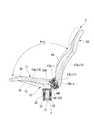
背凭れ12は、図4に示すように、背凭れフレーム17の接合プレート17bが座フレーム14の接合プレート14bに複数のボルト24A,24Bによって締結されることにより、座11に結合されている。
以下、説明の便宜上、背凭れ12については、椅子1の左右方向と合致する方向を幅方向と呼び、椅子1の左右方向と高さ方向に対して略直交し、かつ接合プレート17bに沿った方向を厚み方向と呼ぶ。この実施形態の場合、背凭れフレーム17側の接合プレート17bは、幅方向の両側の端縁の各一箇所がボルト24Aによって座フレーム14側の対応個所に締結され、幅方向中央位置の上下二箇所と、幅方向の各端縁と幅方向中央位置との間の各一箇所がボルト24Bによって座フレーム14側の接合プレート14bの対応箇所に締結されている。As shown in FIG. 4, the
Hereinafter, for convenience of description, with respect to the
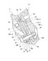
図7は、背凭れ12と座11の幅方向の一方の端縁の結合部と、幅方向中央位置の下部側の結合部が現れるように切った背凭れ12と座11の断面を示す図である。
図7に示すように、背凭れフレーム17の接合プレート17bの連結面17b−lには、座フレーム14の接合プレート14b方向に向かって突出する複数のボス部25A,25Bが一体に形成されている。ボス部25Aは、接合プレート17bの幅方向の両側の端縁の各一箇所に形成され、ボス部25Bは、接合プレート17bの幅方向中央位置の上下二箇所と、幅方向の各端縁と幅方向中央位置との間の各一箇所に形成されている。各ボス部25A,25Bには、ボルト24A,24Bの軸部が挿入される挿通孔26が形成されている。なお、ボス部25Aは、背凭れフレーム17の厚み方向全体で見たときに、背凭れフレーム17の厚み方向の一端部寄り(前上端部寄り)に配置されている。また、残余のボス部25Bは、ボス部25Aよりも背凭れフレーム17の厚み方向の他端部寄り(後下端部寄り)に配置されている。FIG. 7 is a view showing a cross section of the
As shown in FIG. 7, a plurality of
座フレーム14の接合プレート14bの連結面14b−uには、背凭れフレーム17側のボス部25Aと対向するように突出するボス部27が一体に形成されている。このボス部27には、ボルト24Aの軸部が挿入される挿通孔28が形成されている。また、座フレーム14側の接合プレート14bのうち、背凭れフレーム17側の各ボス部25Bと対向する位置には、一部が背凭れフレーム17側と逆側に膨出するように肉厚部29が設けられている。この肉厚部29には、ネジ孔30が形成されている。ネジ孔30には、略円筒状の進退部材31が螺合されている。なお、背凭れ12側のボス部25Aと座11側のボス部27の端面同士と、背凭れ12側のボス部25Bと座11側の進退部材31の端面同士は、それぞれ当接可能とされている。 The
図8は、進退部材31を示す図であり、図9は、進退部材31を回転調整する際の様子を示した図7と同様の図である。
進退部材31は、図8に示すように、外周面に雄ネジ32が形成され、軸心部には六角孔33が形成されている。進退部材31は、外周の雄ネジ32部分がネジ孔30に螺合される。進退部材31の雄ネジ32と、ネジ孔30の雌ネジ部分とは、進退部材31の突出高さを調整するためのネジ機構37を構成している。進退部材31とネジ孔30とは、座11側の第1面(連結面14b−u)と背凭れ12側の第2面(連結面17b−l)の間の一部の離間幅を調整する調整手段を構成している。FIG. 8 is a view showing the advancing / retreating
As shown in FIG. 8, the advancing / retreating
また、進退部材31は、図9に示すように、六角孔33に六角レンチ39が挿し込まれ、その状態で六角レンチ39によって回転操作される。進退部材31は、ネジ孔30に対するネジ込み量を操作することにより、接合プレート14bから背凭れフレーム17方向への突出高さが調整される。換言すると、進退部材31は、ネジ込み量を操作することにより、相手当接面である背凭れフレーム17側のボス部25Bとの当接位置を調整される。
なお、ネジ孔30と進退部材31の六角孔33にはボルト24Bの軸部が挿入される。進退部材31の六角孔33は、ボルト24Bの軸部が挿入される挿通孔を構成している。As shown in FIG. 9, the advancing / retreating
The shaft portion of the
また、図7,図9に示すように、背凭れフレーム17側の接合プレート17bの連結面17b−lと逆側の面には、各挿通孔26の周囲を取り囲むようにナット34A,34Bが溶接固定されている。ナット34Aは、接合プレート17b上のボス部25Aの背部に対応する箇所に固定され、ナット34Bは、接合プレート17b上のボス部25Bの背部に対応する箇所に固定されている。ナット34Aには、座フレーム14側のボス部27と背凭れフレーム17側のボス部25Aを貫通したボルト24Aの軸部が螺合される。また、ナット34Bには、座フレーム14側の進退部材31と背凭れフレーム17側のボス部25Bを貫通したボルト24Bの軸部が螺合される。なお、図7,図9中の符号35は、ボルト24Bの頭部と座フレーム14側の肉厚部29との間に介装されたスペーサである。
この実施形態の場合、ボルト24Aとナット34Aは、背凭れフレーム17の厚み方向の一端部寄りとなる部分を座フレーム14の対応箇所に連結するための連結手段を構成し、ボルト24Bとナット34Bは、背凭れフレーム17の厚み方向の他端部寄りとなる部分を座フレーム14の対応箇所に連結するための連結手段を構成している。Further, as shown in FIGS. 7 and 9, nuts 34A, 34B are provided on the surface of the
In the case of this embodiment, the
ここで、座フレーム14の接合プレート14bのうちの、ボス部27と進退部材31の保持部とは、背凭れ12の厚み方向と幅方向の両方について離間している。同様に、背凭れフレーム17の接合プレート17bのうちの、ボス部25Aとボス部25Bとは、背凭れ12の厚み方向と幅方向の両方について離間している。この実施形態の場合、接合プレート14b上におけるボス部27と進退部材31の保持部の間の領域と、接合プレート17b上におけるボス部25Aとボス部25Bの間の領域は、ボルト24B及びナット34Bの締結に伴う面の撓み変形を許容する撓み許容部40を構成している。なお、接合プレート14bや接合プレート17bは、これらの肉厚や材質等によって撓み易さを適宜設定することができるが、撓み許容部40は、接合プレート14b,17bのいずれか一方のみに設けるようにしても良い。 Here, in the
また、座フレーム14の接合プレート14bのうちの、ボス部27と進退部材31の各周囲は、弾性変形可能なモールド樹脂16によって被覆されている。背凭れフレーム17の接合プレート17bのうちの、ボス部25A,25Bの各周囲も同様に弾性変形可能なモールド樹脂16によって被覆されている。これらの部分に被覆されているモールド樹脂16は、背凭れフレーム17と座フレーム14をボルト24A,24Bとナット34A,34Bによって締結するときに、締結荷重を受けて撓み変形する。
なお、座11の下面側の後縁部のモールド樹脂16には、座11の下面の前方側から工具によって各ボルト24A,24Bにアクセスし得るように、作業孔41が形成されている。Further, the periphery of the
A working
実際に、座11の後部上面に背凭れ12を連結する場合には、座11の後部の接合プレート14bの連結面14b−uに、背凭れ12側の接合プレート17bの連結面17b−lを重ね合わせ、各ボルト24A,24Bを作業孔41に挿し込んだ後に、工具を用いて各ボルト24A,24Bの先端部を背凭れ12側の対応するナット34A,34Bに締め込む。このとき、座フレーム14側の進退部材31は、図7に示すように、ボス部27とほぼ同高さだけ突出しているものとする。ナット34A,34Bに対する各ボルト24A,24Bの締め込みが進むと、座フレーム14側のボス部27の端面が背凭れフレーム17側の対応するボス部25Aの端面に強固に押し付けられるとともに、座フレーム14側の進退部材31の端面が背凭れフレーム17側の対応するボス部25Bの端面に強固に押し付けられる。この結果、背凭れ12が座11に対して締結固定される。なお、このとき、座11側のボス部27や進退部材31の周囲に配置されているモールド樹脂16と、背凭れ12側のボス部25A,25Bの周囲に配置されているモールド樹脂16は相互に押し付けられて圧縮変形する。 In practice, when connecting the
また、この状態から座11に対する背凭れ12の設置角度を調整する場合には、作業孔41に工具を差し込んで、幅方向中央寄りに配置されているボルト24Bを弛めて取り外す(図9参照)。この後に、図9に示すように、ボルト24Bを取り去った作業孔41から進退部材31の六角孔33に六角レンチ39を挿し込み、六角レンチ39を回すことによって進退部材31の突出高さを変更する。図10は、進退部材31の突出高さを低く変更したときの状態を示している。 Further, when adjusting the installation angle of the
次に、この状態から作業孔41に再度ボルト24Bを挿し込み、工具によってボルト24Bの先端部を対応するナット34Bに締め込む。このとき、例えば、図10に示すように進退部材31の突出高さが低く変更されている場合には、ボルト24Bの締め込み可能な量が増大する。こうして、ボルト24Bが締め込まれると、背凭れ12が上部側のボス部25A,27同士の当接部を支点として傾動し、図11に示すように、座11に対する背凭れ12の設置角度が変更される。図11では、座11に対する背凭れ12の開き角度が、図6に示すAからA+αに拡がっている。
また、進退部材31の突出高さを高く変更した場合には、ボルト24Bの締め込み可能な量が減少し、座11に対する背凭れ12の開き角度が減少する。
なお、ボルト24Bが対応するナット34Bに対して締め込まれると、接合プレート14b,17bの撓み許容部40が撓み変形し、それによって進退部材31の端面とボス部25Bとがより広い面積で当接し易くなる。Next, from this state, the
Further, when the protrusion height of the advancing / retreating
When the
以上のように、この実施形態に係る椅子1においては、座11側の接合プレート14bに、調整手段を構成すネジ孔30と進退部材31が設けられているため、進退部材31の突出高さを調整することにより、座11に対する背凭れ12の設置角度を容易に、かつ適切に調整することができる。
なお、この実施形態においては、調整手段を構成するネジ孔30と進退部材31が座11側に設けられているが、ネジ孔30と進退部材31は、背凭れ12側に設けるようにしても良い。また、ネジ孔30と進退部材31は、座11側と背凭れ12側の両方に設けるようにしても良い。As described above, in the
In addition, in this embodiment, the
特に、この実施形態に係る椅子1においては、進退部材31がネジ機構37によって高さ調整可能とされているため、進退部材31の突出高さを無段階に容易に微調整することができる。 Particularly, in the
また、この実施形態に係る椅子1の場合、背凭れ12と座11の複数箇所の連結手段がすべてボルト24A,24Bとナット34A,34Bを主とする構成とされているため、全体の構成を簡素化できるという利点がある。 In addition, in the case of the
また、この実施形態に係る椅子1においては、進退部材31に六角孔33が設けられ、その六角孔33が、ボルト24Bの軸部を挿入する挿通孔として機能している。このため、ボルト24Bとナット34Bが相互に締め込まれたときに、ボルト24Bとナット34Bによる締結力が進退部材31に効率良く伝達される。このため、背凭れ12側のボス部25Bと進退部材31とを強固に押し当て、背凭れ12と座11の結合をより強固にすることができる。 Further, in the
さらに、この実施形態に係る椅子1では、座11側と背凭れ12側の少なくとも一方の接合プレート14b,17bに撓み許容部40が設けられているため、ボルト24Bがナット34Bに締め込まれたときに、撓み許容部40が撓み変形することにより、進退部材31の端面とボス部25Bの端面とをより広い面積で当接させることができる。したがって、この構造により、ボルト24Bとナット34Bによる締結固定をより安定させることができる。 Further, in the
特に、この実施形態においては、背凭れ12と座11の中央領域で突き合わせられるボス部25Bと進退部材31が、背凭れ12と座11の幅方向両側の端縁同士で突き合わせられるボス部25Aとボス部27に対して、背凭れ12の厚み方向と幅方向の両方に離間して配置されている。このため、撓み許容部40の撓み代を容易に大きく確保することができる。したがって、ボルト24Bとナット34Bの締め込み時に、進退部材31の端面とボス部25Bの端面とをより広い面積で当接させ易くなる。 In particular, in this embodiment, the
また、この実施形態に係る椅子1においては、座フレーム14側のボス部27と進退部材31の各周囲と、背凭れフレーム17側のボス部25A,25Bの各周囲が弾性変形可能なモールド樹脂16によって被覆されている。このため、座11に対する背凭れ12の設置角度を調整した場合にも、ボス部27,25A,25Bや進退部材31の周囲でモールド樹脂16が弾性変形することによって座11と背凭れ12の間に不要な隙間ができるのを防止することができる。 In addition, in the
つづいて、図12,図13に示す第2の実施形態について説明する。
第2の実施形態に係る什器は、第1の実施形態の椅子1と構成の一部のみが異なる椅子である。以下では、第1の実施形態との相違点を中心にして説明し、第1の実施形態と共通部分に同一符号を付して重複する説明を省略する。Next, a second embodiment shown in FIGS. 12 and 13 will be described.
The furniture according to the second embodiment is a chair that is different from the
図12は、第1の実施形態の図7に対応する図であり、図13は、第1の実施形態の図10に対応する図である。
第2の実施形態の椅子は、第1の実施形態の椅子とは、座フレーム14と背凭れフレーム17の幅方向両側の端縁同士を連結する連結手段の構成が異なっている。12 is a diagram corresponding to FIG. 7 of the first embodiment, and FIG. 13 is a diagram corresponding to FIG. 10 of the first embodiment.
The chair of the second embodiment is different from the chair of the first embodiment in the structure of the connecting means for connecting the edges of the
即ち、座フレーム14の接合プレート14bには、背凭れフレーム17方向に向かって突出する支持ボス50が突設され、支持ボス50に椅子の幅方向に沿って延出する連結ピン51が保持されている。これに対し、背凭れフレーム17の接合プレート17bには、座フレーム14方向に向かって突出する支持ボス52が突設され、その支持ボス52に、連結ピン51が回動可能に嵌合される嵌合孔53(ピン嵌合部)が形成されている。座フレーム14の接合プレート14bと、背凭れフレーム17の接合プレート17bの幅方向両側の端縁同士は、連結ピン51が嵌合孔53に嵌合されることによって相互に連結されている。
なお、この実施形態においては、連結ピン51が座11側に設けられ、嵌合孔53が背凭れ12側に設けられているが、連結ピン51を背凭れ12側に設け、嵌合孔53を座11側に受けるようにしても良い。That is, on the
Although the connecting
実際に、座11の後部上面に背凭れ12を連結する場合には、座フレーム14の接合プレート14bの幅方向両側の縁部に保持された連結ピン51を、背凭れフレーム17側の嵌合孔53に嵌合し、その状態で各ボルト24Bを作業孔41に差し込んだ後に、工具を用いて各ボルト24Bの先端部を背凭れフレーム17側の対応するナット34Bに締め込む。 In fact, when connecting the
図12は、座フレーム14の接合プレート14bから進退部材31を設定高さ突出させた状態を示しており、図13は、図12に示す状態から進退部材31の突出高さを低く変更した状態を示している。
例えば、図12に示す状態から座11に対する背凭れ12の設置角度を増大方向に変更する場合には、第1の実施形態と同様に、ボルト24Bを一旦外して六角レンチ等によって進退部材31を回転させ、それによって進退部材31の突出高さを変更する。この後、取り外したボルト24Bを再度対応するナット34Bに対して締め込む。こうして、ボルト24Bが対応するナット34Bに締め込まれると、背凭れ12が、連結ピン51の嵌合孔53との嵌合部分を支点として傾動し、図13に示すように、座11に対する背凭れ12の設置角度が変更させる。FIG. 12 shows a state in which the advancing / retreating
For example, when the installation angle of the
この第2の実施形態に係る椅子は、第1の実施形態と基本構成がほぼ同様であるため、第1の実施形態とほぼ同様の効果を得ることができる。ただし、この第2の実施形態に係る椅子の場合、座フレーム14の接合プレート14bと背凭れフレーム17の接合プレート17bの一部が、連結ピン51と嵌合孔53の嵌合によって回転可能に連結されている。このため、背凭れ12の設置角度を変更するためにボルト24Bを対応するナット34Bに締め込んだときに、連結ピン51と嵌合孔53による嵌合部分を支点として、背凭れ12の角度をスムーズに変化させることができる。したがって、この構造を採用することにより、背凭れ12の設置角度の調整を容易に行うことが可能になるとともに、座11や背凭れ12の一部に不要な応力が残留するのを抑制することができる。 Since the chair according to the second embodiment has substantially the same basic configuration as that of the first embodiment, it is possible to obtain substantially the same effect as that of the first embodiment. However, in the case of the chair according to the second embodiment, a part of the
なお、本発明は上記の実施形態に限定されるものではなく、その要旨を逸脱しない範囲で種々の設計変更が可能である。例えば、第1の実施形態においては、座11と背凭れ12の幅方向両側の端縁を連結するボルト24A及びナット34A部分には、調整手段であるネジ孔30と進退部材31が設けられていないが、幅方向両側の端縁のボルト24A及びナット34Aの設置部分にも調整手段を設けるようにしても良い。また、上記の各実施形態においては、連結手段であるボルト24B及びナット34Bと同軸に調整手段であるネジ孔30と進退部材31とが設けられているが、調整手段は連結手段と離間させて(非同軸に)配置するようにしても良い。たとえば、上記の第1の実施形態において、調整手段であるネジ孔30と進退部材31を座11と背凭れ12の幅方向の中央領域に配置してあれば、幅方向中央領域のボルト24B及びナット34Bを廃止することも可能である。 The present invention is not limited to the above embodiment, and various design changes can be made without departing from the scope of the invention. For example, in the first embodiment, a
また、上記の実施形態においては、座フレーム14の後端の接合プレート14bの連結面14b−uと、背凭れフレーム17の下端の接合プレート17bの連結面17b−lとは、傾斜した状態で相互に対向しているが、これらの連結面14b−u,17b−lは鉛直方向を向くように設定されていても良く、また、水平方向を向くように設定されていても良い。
さらに、上記の実施形態に係る什器は、背凭れ12が座11の後端部に起立状態で設置された椅子であるが、背凭れが脚部材の上部に起立状態で設置された椅子であっても良い。この場合には、脚部材と背凭れの相互に対向する面に、上記の実施形態と同様の連結手段や調整手段を設ける。
また、上述した各実施形態に係る什器は椅子であるが、什器は、椅子に限らず、什器本体部材に対して起立部材が結合されるものであれば、他の形態のものであっても良い。In the above embodiment, the connecting
Further, the furniture according to the above-described embodiment is a chair in which the
Further, the furniture according to each of the above-described embodiments is a chair, but the furniture is not limited to the chair, and other forms may be used as long as the standing member is coupled to the furniture main body member. good.
11 座(什器本体部材)
12 背凭れ(起立部材)
13 連結脚(什器本体部材)
16 モ−ルド樹脂(弾性部材)
24A,24B ボルト(連結手段)
30 ネジ孔(調整手段)
31 進退部材(調整手段)
33 六角孔(挿通孔)
34A,34B ナット(連結手段)
37 ネジ機構
40 撓み許容部
51 連結ピン(連結手段)
53 嵌合孔(ピン嵌合部,連結手段)11 seats (main body fixtures)
12 Backrest (standing member)
13 Connecting legs (main body of furniture)
16 mold resin (elastic member)
24A, 24B bolt (connecting means)
30 screw holes (adjustment means)
31 Advancement / retraction member (adjustment means)
33 Hexagonal hole (insertion hole)
34A, 34B nut (connecting means)
37
53 Fitting hole (pin fitting part, connecting means)
Claims (8)
Translated fromJapanese前記什器本体部材から上方に起立した状態で前記什器本体部材に対して連結され、前記什器本体部材の第1面に対向する第2面を有する起立部材と、
前記什器本体部材の前記第1面と前記起立部材の前記第2面とを、複数箇所で連結する連結手段と、
前記什器本体部材と前記起立部材の少なくともいずれか一方に設けられ、対向する前記第1面と前記第2面の間の一部の離間幅を調整する調整手段と、
を備え、
前記調整手段は、前記什器本体部材と前記起立部材の少なくともいずれか一方に進退位置調整可能に保持される進退部材を有し、
前記連結手段は、前記進退部材の端面を前記第1面と前記第2面のいずれか一方に当接させることを特徴とする什器。Furniture main body member,
A standing member that is connected to the furniture main body member in a state of standing upright from the furniture main body member and has a second surface facing the first surface of the furniture main body member;
Connection meansfor connecting the first surface of the furniture main body member and the second surface of the standing member at a plurality of points;
Adjustment means provided on at least one of the furniture main body member and the standing member, and adjusting a separation width of a part between the first surface and the second surface facing each other.
Equipped with
The adjusting means has an advancing / retreating member that is held in at least one of the furniture main body member and the standing member so that the advancing / retreating position can be adjusted.
The connecting means causes the end surface of the advancing / retreating member to contact either one of the first surface and the second surface .
前記調整手段は、前記厚み方向の他端部寄りとなる部分において、前記什器本体部材と前記起立部材の少なくともいずれか一方に設けられていることを特徴とする請求項1または2に記載の什器。The connecting means divides the first surface and the second surface into a portion closer to one end portion in the thickness direction of the standing member and a portion closer to the other end portion in the thickness direction than a portion closer to the one end portion. It is equipped with bolts and nuts that connect with
The furniture according to claim 1 or 2, wherein the adjusting means is provided on at least one of the furniture main body member and the upright member in a portion near the other end in the thickness direction. ..
前記調整手段は、前記厚み方向の他端部寄りとなる部分において、前記什器本体部材と前記起立部材の少なくともいずれか一方に設けられていることを特徴とする請求項1または2に記載の什器。The connecting means connects the first surface and the second surface to each other so as to be rotatable relative to each other at a portion closer to one end in the thickness direction of the upright member, and the first and second fitting surfaces, A bolt and a nut that connect the first surface and the second surface at a portion closer to the other end in the thickness direction than a portion closer to the one end,
The furniture according to claim 1 or 2, wherein the adjusting means is provided on at least one of the furniture main body member and the upright member in a portion near the other end in the thickness direction. ..
前記撓み許容部は、前記一端部寄りとなる部分の前記連結手段の配置位置と、前記他端部寄りとなる部分の前記連結手段の配置位置の間に少なくとも設けられていることを特徴とする請求項6に記載の什器。The connecting means arranged at the portion closer to the other end is arranged at a position separated from the connecting means arranged at the portion closer to the one end in the width direction of the standing member. And
The bending allowance portion is provided at least between an arrangement position of the connecting means in a portion closer to the one end portion and an arrangement position of the connecting means in a portion closer to the other end portion. The furniture according to claim 6.
Priority Applications (3)
| Application Number | Priority Date | Filing Date | Title |
|---|---|---|---|
| JP2015170868AJP6695113B2 (en) | 2015-08-31 | 2015-08-31 | Furniture |
| PCT/JP2016/075311WO2017038812A1 (en) | 2015-08-31 | 2016-08-30 | Article of furniture |
| CN201680031519.3ACN107613812B (en) | 2015-08-31 | 2016-08-30 | Daily utensil |
Applications Claiming Priority (1)
| Application Number | Priority Date | Filing Date | Title |
|---|---|---|---|
| JP2015170868AJP6695113B2 (en) | 2015-08-31 | 2015-08-31 | Furniture |
Publications (2)
| Publication Number | Publication Date |
|---|---|
| JP2017046784A JP2017046784A (en) | 2017-03-09 |
| JP6695113B2true JP6695113B2 (en) | 2020-05-20 |
Family
ID=58187626
Family Applications (1)
| Application Number | Title | Priority Date | Filing Date |
|---|---|---|---|
| JP2015170868AActiveJP6695113B2 (en) | 2015-08-31 | 2015-08-31 | Furniture |
Country Status (3)
| Country | Link |
|---|---|
| JP (1) | JP6695113B2 (en) |
| CN (1) | CN107613812B (en) |
| WO (1) | WO2017038812A1 (en) |
Family Cites Families (5)
| Publication number | Priority date | Publication date | Assignee | Title |
|---|---|---|---|---|
| IT1230040B (en)* | 1988-07-21 | 1991-09-24 | Zanotta S P A | SOFA OR SEATS WITH BACKS AND / OR ARMRESTS FREELY POSITIONABLE, AS WELL AS POSITIONABLE FURNITURE. |
| JP3639628B2 (en)* | 1995-01-11 | 2005-04-20 | 株式会社サーメル | Chair |
| JP5259993B2 (en)* | 2007-07-09 | 2013-08-07 | 株式会社岡村製作所 | Chair |
| CN102176847B (en)* | 2008-10-16 | 2014-04-09 | 株式会社冈村制作所 | Chair |
| JP5378870B2 (en)* | 2009-04-28 | 2013-12-25 | 株式会社岡村製作所 | Connection structure between seat and backrest |
- 2015
- 2015-08-31JPJP2015170868Apatent/JP6695113B2/enactiveActive
- 2016
- 2016-08-30WOPCT/JP2016/075311patent/WO2017038812A1/ennot_activeCeased
- 2016-08-30CNCN201680031519.3Apatent/CN107613812B/ennot_activeExpired - Fee Related
Also Published As
| Publication number | Publication date |
|---|---|
| CN107613812A (en) | 2018-01-19 |
| JP2017046784A (en) | 2017-03-09 |
| CN107613812B (en) | 2021-06-15 |
| WO2017038812A1 (en) | 2017-03-09 |
Similar Documents
| Publication | Publication Date | Title |
|---|---|---|
| KR101235150B1 (en) | Office chair | |
| JP2020058764A (en) | Chair | |
| KR100856576B1 (en) | Pelvic protective chair | |
| JP6608136B2 (en) | Chair turning mechanism and chair | |
| JP6695113B2 (en) | Furniture | |
| JP6078290B2 (en) | Chair | |
| WO2018207805A1 (en) | Support structure for fixture forming member, and fixture provided with same | |
| JP5184908B2 (en) | Chair with armrests | |
| JP2006271623A (en) | Chair | |
| JP7288023B2 (en) | bench seat device | |
| KR20110133942A (en) | Lumbar support device of chair | |
| JP2003135212A (en) | Connecting chair | |
| JP7458739B2 (en) | Load-bearing structures and fixtures | |
| WO2016063826A1 (en) | Chair | |
| JP6923356B2 (en) | Support structure of fixture components and fixtures equipped with it | |
| JP6155007B2 (en) | Connecting structure and fixtures | |
| JP2009106412A (en) | Leg equipment for furniture such as chairs | |
| JP5547842B1 (en) | Wheelchair removable table | |
| JP6905383B2 (en) | furniture | |
| JP6858624B2 (en) | Optional parts mounting structure, optional parts, and fixtures | |
| KR102514183B1 (en) | Office chair with elastic restoration structure of joint type backrest | |
| KR200284313Y1 (en) | A chair frame with back frame capable of flexible movement | |
| JP2006141859A (en) | Chair having waist supporting part | |
| JP7217105B2 (en) | Chair | |
| KR200411864Y1 (en) | Chair waist support |
Legal Events
| Date | Code | Title | Description |
|---|---|---|---|
| A621 | Written request for application examination | Free format text:JAPANESE INTERMEDIATE CODE: A621 Effective date:20180719 | |
| RD03 | Notification of appointment of power of attorney | Free format text:JAPANESE INTERMEDIATE CODE: A7423 Effective date:20181012 | |
| A131 | Notification of reasons for refusal | Free format text:JAPANESE INTERMEDIATE CODE: A131 Effective date:20190625 | |
| A601 | Written request for extension of time | Free format text:JAPANESE INTERMEDIATE CODE: A601 Effective date:20190826 | |
| A521 | Request for written amendment filed | Free format text:JAPANESE INTERMEDIATE CODE: A523 Effective date:20191021 | |
| TRDD | Decision of grant or rejection written | ||
| A01 | Written decision to grant a patent or to grant a registration (utility model) | Free format text:JAPANESE INTERMEDIATE CODE: A01 Effective date:20200327 | |
| A61 | First payment of annual fees (during grant procedure) | Free format text:JAPANESE INTERMEDIATE CODE: A61 Effective date:20200421 | |
| R150 | Certificate of patent or registration of utility model | Ref document number:6695113 Country of ref document:JP Free format text:JAPANESE INTERMEDIATE CODE: R150 | |
| R250 | Receipt of annual fees | Free format text:JAPANESE INTERMEDIATE CODE: R250 | |
| R250 | Receipt of annual fees | Free format text:JAPANESE INTERMEDIATE CODE: R250 | |
| R250 | Receipt of annual fees | Free format text:JAPANESE INTERMEDIATE CODE: R250 |