JP6694796B2 - Cell transfer device - Google Patents
Cell transfer deviceDownload PDFInfo
- Publication number
- JP6694796B2 JP6694796B2JP2016204575AJP2016204575AJP6694796B2JP 6694796 B2JP6694796 B2JP 6694796B2JP 2016204575 AJP2016204575 AJP 2016204575AJP 2016204575 AJP2016204575 AJP 2016204575AJP 6694796 B2JP6694796 B2JP 6694796B2
- Authority
- JP
- Japan
- Prior art keywords
- cells
- chip
- head
- sample
- unit
- Prior art date
- Legal status (The legal status is an assumption and is not a legal conclusion. Google has not performed a legal analysis and makes no representation as to the accuracy of the status listed.)
- Active
Links
- 238000012546transferMethods0.000titleclaimsdescription53
- 238000000034methodMethods0.000claimsdescription52
- 230000008569processEffects0.000claimsdescription22
- 238000012545processingMethods0.000claimsdescription20
- 230000012292cell migrationEffects0.000claimsdescription13
- 238000007599dischargingMethods0.000claimsdescription11
- 230000033001locomotionEffects0.000claimsdescription5
- 238000003384imaging methodMethods0.000description34
- 150000001875compoundsChemical class0.000description19
- 239000002609mediumSubstances0.000description19
- CIWBSHSKHKDKBQ-JLAZNSOCSA-NAscorbic acidChemical compoundOC[C@H](O)[C@H]1OC(=O)C(O)=C1OCIWBSHSKHKDKBQ-JLAZNSOCSA-N0.000description17
- 230000007246mechanismEffects0.000description14
- 238000010586diagramMethods0.000description11
- 230000000052comparative effectEffects0.000description9
- 238000012937correctionMethods0.000description9
- 238000004113cell cultureMethods0.000description6
- 239000000243solutionSubstances0.000description6
- 238000002474experimental methodMethods0.000description5
- 239000000463materialSubstances0.000description5
- 239000011159matrix materialSubstances0.000description5
- 238000012790confirmationMethods0.000description4
- 239000003814drugSubstances0.000description4
- 230000006870functionEffects0.000description4
- 239000011521glassSubstances0.000description4
- 238000011084recoveryMethods0.000description4
- 229940126062Compound ADrugs0.000description3
- PEDCQBHIVMGVHV-UHFFFAOYSA-NGlycerineChemical compoundOCC(O)COPEDCQBHIVMGVHV-UHFFFAOYSA-N0.000description3
- NLDMNSXOCDLTTB-UHFFFAOYSA-NHeterophylliin ANatural productsO1C2COC(=O)C3=CC(O)=C(O)C(O)=C3C3=C(O)C(O)=C(O)C=C3C(=O)OC2C(OC(=O)C=2C=C(O)C(O)=C(O)C=2)C(O)C1OC(=O)C1=CC(O)=C(O)C(O)=C1NLDMNSXOCDLTTB-UHFFFAOYSA-N0.000description3
- 239000006143cell culture mediumSubstances0.000description3
- 230000009087cell motilityEffects0.000description3
- 238000011109contaminationMethods0.000description3
- 229940079593drugDrugs0.000description3
- 230000003028elevating effectEffects0.000description3
- 230000035945sensitivityEffects0.000description3
- 238000012360testing methodMethods0.000description3
- 108091003079Bovine Serum AlbuminProteins0.000description2
- WSFSSNUMVMOOMR-UHFFFAOYSA-NFormaldehydeChemical compoundO=CWSFSSNUMVMOOMR-UHFFFAOYSA-N0.000description2
- 230000004308accommodationEffects0.000description2
- 230000004931aggregating effectEffects0.000description2
- 239000006285cell suspensionSubstances0.000description2
- 239000000356contaminantSubstances0.000description2
- 238000009795derivationMethods0.000description2
- 238000001514detection methodMethods0.000description2
- 238000007689inspectionMethods0.000description2
- LVTJOONKWUXEFR-FZRMHRINSA-NprotoneodioscinNatural productsO(C[C@@H](CC[C@]1(O)[C@H](C)[C@@H]2[C@]3(C)[C@H]([C@H]4[C@@H]([C@]5(C)C(=CC4)C[C@@H](O[C@@H]4[C@H](O[C@H]6[C@@H](O)[C@@H](O)[C@@H](O)[C@H](C)O6)[C@@H](O)[C@H](O[C@H]6[C@@H](O)[C@@H](O)[C@@H](O)[C@H](C)O6)[C@H](CO)O4)CC5)CC3)C[C@@H]2O1)C)[C@H]1[C@H](O)[C@H](O)[C@H](O)[C@@H](CO)O1LVTJOONKWUXEFR-FZRMHRINSA-N0.000description2
- 239000011347resinSubstances0.000description2
- 229920005989resinPolymers0.000description2
- 230000000717retained effectEffects0.000description2
- DAEPDZWVDSPTHF-UHFFFAOYSA-Msodium pyruvateChemical compound[Na+].CC(=O)C([O-])=ODAEPDZWVDSPTHF-UHFFFAOYSA-M0.000description2
- 206010052747Adenocarcinoma pancreasDiseases0.000description1
- 101100012466Drosophila melanogaster Sras geneProteins0.000description1
- 241001465754MetazoaSpecies0.000description1
- 239000012979RPMI mediumSubstances0.000description1
- 239000012980RPMI-1640 mediumSubstances0.000description1
- 239000003242anti bacterial agentSubstances0.000description1
- 229940088710antibiotic agentDrugs0.000description1
- -1antibodiesSubstances0.000description1
- 238000007630basic procedureMethods0.000description1
- 239000003153chemical reaction reagentSubstances0.000description1
- 238000012258culturingMethods0.000description1
- 230000007423decreaseEffects0.000description1
- 239000012091fetal bovine serumSubstances0.000description1
- 239000007850fluorescent dyeSubstances0.000description1
- 239000012634fragmentSubstances0.000description1
- 238000007710freezingMethods0.000description1
- 239000001963growth mediumSubstances0.000description1
- 239000012535impuritySubstances0.000description1
- 239000007788liquidSubstances0.000description1
- 239000004973liquid crystal related substanceSubstances0.000description1
- 230000003287optical effectEffects0.000description1
- 201000002094pancreatic adenocarcinomaDiseases0.000description1
- 238000005192partitionMethods0.000description1
- 239000002504physiological saline solutionSubstances0.000description1
- 230000002035prolonged effectEffects0.000description1
- 239000008213purified waterSubstances0.000description1
- 238000011160researchMethods0.000description1
- 230000004044responseEffects0.000description1
- 210000002966serumAnatomy0.000description1
- 229940054269sodium pyruvateDrugs0.000description1
- 239000013589supplementSubstances0.000description1
- 238000011282treatmentMethods0.000description1
- XLYOFNOQVPJJNP-UHFFFAOYSA-NwaterChemical compoundOXLYOFNOQVPJJNP-UHFFFAOYSA-N0.000description1
Images


Classifications
- C—CHEMISTRY; METALLURGY
- C12—BIOCHEMISTRY; BEER; SPIRITS; WINE; VINEGAR; MICROBIOLOGY; ENZYMOLOGY; MUTATION OR GENETIC ENGINEERING
- C12M—APPARATUS FOR ENZYMOLOGY OR MICROBIOLOGY; APPARATUS FOR CULTURING MICROORGANISMS FOR PRODUCING BIOMASS, FOR GROWING CELLS OR FOR OBTAINING FERMENTATION OR METABOLIC PRODUCTS, i.e. BIOREACTORS OR FERMENTERS
- C12M33/00—Means for introduction, transport, positioning, extraction, harvesting, peeling or sampling of biological material in or from the apparatus
- C12M33/04—Means for introduction, transport, positioning, extraction, harvesting, peeling or sampling of biological material in or from the apparatus by injection or suction, e.g. using pipettes, syringes, needles
- C12M33/06—Means for introduction, transport, positioning, extraction, harvesting, peeling or sampling of biological material in or from the apparatus by injection or suction, e.g. using pipettes, syringes, needles for multiple inoculation or multiple collection of samples
- C—CHEMISTRY; METALLURGY
- C12—BIOCHEMISTRY; BEER; SPIRITS; WINE; VINEGAR; MICROBIOLOGY; ENZYMOLOGY; MUTATION OR GENETIC ENGINEERING
- C12M—APPARATUS FOR ENZYMOLOGY OR MICROBIOLOGY; APPARATUS FOR CULTURING MICROORGANISMS FOR PRODUCING BIOMASS, FOR GROWING CELLS OR FOR OBTAINING FERMENTATION OR METABOLIC PRODUCTS, i.e. BIOREACTORS OR FERMENTERS
- C12M33/00—Means for introduction, transport, positioning, extraction, harvesting, peeling or sampling of biological material in or from the apparatus
- C12M33/04—Means for introduction, transport, positioning, extraction, harvesting, peeling or sampling of biological material in or from the apparatus by injection or suction, e.g. using pipettes, syringes, needles
- C—CHEMISTRY; METALLURGY
- C12—BIOCHEMISTRY; BEER; SPIRITS; WINE; VINEGAR; MICROBIOLOGY; ENZYMOLOGY; MUTATION OR GENETIC ENGINEERING
- C12M—APPARATUS FOR ENZYMOLOGY OR MICROBIOLOGY; APPARATUS FOR CULTURING MICROORGANISMS FOR PRODUCING BIOMASS, FOR GROWING CELLS OR FOR OBTAINING FERMENTATION OR METABOLIC PRODUCTS, i.e. BIOREACTORS OR FERMENTERS
- C12M23/00—Constructional details, e.g. recesses, hinges
- C12M23/02—Form or structure of the vessel
- C12M23/12—Well or multiwell plates
Landscapes
- Health & Medical Sciences (AREA)
- Life Sciences & Earth Sciences (AREA)
- Wood Science & Technology (AREA)
- Organic Chemistry (AREA)
- Engineering & Computer Science (AREA)
- Bioinformatics & Cheminformatics (AREA)
- Chemical & Material Sciences (AREA)
- Zoology (AREA)
- Biomedical Technology (AREA)
- Sustainable Development (AREA)
- Microbiology (AREA)
- Biotechnology (AREA)
- Biochemistry (AREA)
- General Engineering & Computer Science (AREA)
- General Health & Medical Sciences (AREA)
- Genetics & Genomics (AREA)
- Molecular Biology (AREA)
- Clinical Laboratory Science (AREA)
- Apparatus Associated With Microorganisms And Enzymes (AREA)
- Automatic Analysis And Handling Materials Therefor (AREA)
Description
Translated fromJapanese本発明は、細胞を保持するディッシュから細胞を受け入れるウェルを有するプレートへ細胞を移動させる細胞移動装置に関する。 The present invention relates to a cell transfer device for transferring cells from a cell-holding dish to a plate having wells for receiving the cells.
例えば医療や生物学的な研究の用途では、単細胞、或いは細胞が三次元的に凝集してなる細胞凝集塊(以下、これらを本明細書では単に細胞という)が、観察、薬効確認、検査若しくは培養等の処理作業のために、マトリクス配列されたウェルを有するマイクロプレートの、前記ウェルに収容されることがある。ウェルに収容される細胞は、細胞を収容可能な凹部を有するディッシュ上において選別される。この選別に先立ち、ディッシュ上には多量の細胞を含有する細胞培養液が分散され、前記凹部に細胞が保持される。そして、細胞を保持したディッシュの画像が撮像され、画像処理技術によって使用可能な細胞と、使用不可の細胞及び夾雑物とが区分される。しかる後、使用可能な細胞が、吸引チップによって前記凹部から吸引されると共に、吸引された細胞がマイクロプレートのウェルに吐出される(例えば、特許文献1参照)。 For example, in medical and biological research applications, single cells or cell aggregates formed by three-dimensionally aggregating cells (hereinafter, simply referred to as cells in the present specification) are used for observation, confirmation of drug efficacy, examination or For processing operations such as culturing, the microplate having wells arranged in a matrix may be housed in the wells. The cells housed in the wells are sorted on a dish having a recess capable of housing the cells. Prior to this selection, a cell culture solution containing a large amount of cells is dispersed on the dish, and the cells are retained in the recesses. Then, an image of the dish holding the cells is captured, and the usable cells are separated from the unusable cells and contaminants by the image processing technique. Thereafter, usable cells are sucked from the recess by the suction tip, and the sucked cells are discharged into the well of the microplate (for example, refer to Patent Document 1).
前記マイクロプレートにおける各種処理作業においては、複数種類の細胞を対象とすることが求められる場合がある。例えば、複数の検体から採取した細胞に、同じ化合物を反応させるような場合である。このような場合、従来の細胞移動装置では、例えば第1の検体から採取された第1細胞が撒かれた第1ディッシュからチップで当該第1細胞を吸引してマイクロプレートのウェルに吐出させ、続いて、第2の検体から採取された第2細胞が撒かれた第2ディッシュからチップで当該第2細胞を吸引して同じマイクロプレートの他のウェルの吐出させる、という動作が順次実行されることになる。 In various processing operations on the microplate, it may be required to target a plurality of types of cells. For example, this is a case where the same compound is reacted with cells collected from a plurality of specimens. In such a case, in the conventional cell migration device, for example, the first cells are aspirated from the first dish on which the first cells collected from the first sample are sprinkled and discharged into the wells of the microplate, Subsequently, an operation of sequentially aspirating the second cells with a chip from the second dish in which the second cells collected from the second sample are sprinkled and ejecting the cells from other wells of the same microplate is sequentially performed. It will be.
ここで、第1細胞の吸引のために第1ディッシュの細胞培養液中に進入したチップは、第2細胞の吸引には用いることができない。前記第1ディッシュの第1細胞の吸引に使用されたチップは、第1細胞そのもの或いはその断片をチップ内部に収容している、若しくはこれらがチップ表面に付着していることがある。このようなチップを第2細胞の吸引に用いると、当該第2細胞を保持すべきウェルに第1細胞が混入する可能性がある。また、前記第2ディッシュからの第2細胞の吸引の際に、前記チップに付帯している第1細胞を第2ディッシュに侵入させ、第2細胞のみの収容を企図している第2ディッシュ内に第1細胞を混入させてしまうことにもなり得る。このため上記の動作では、第1細胞の吸引と第2細胞の吸引との間に、チップの交換作業が必要となる。この交換作業は、同時に処理される細胞種類が多くなるほど多くなり、チップの廃棄数も増えることになる。また、培養器から細胞を取り出してディッシュに撒く段取り作業が、前記チップの交換作業の度に発生することとなり、多くの時間を要している。 Here, the chip that has entered the cell culture medium of the first dish for aspirating the first cells cannot be used for aspirating the second cells. The chip used for aspirating the first cells of the first dish may contain the first cells or fragments thereof inside the chip, or these may be attached to the surface of the chip. When such a chip is used for aspiration of the second cells, the first cells may be mixed in the wells that should hold the second cells. In addition, during the suction of the second cells from the second dish, the first cells incidental to the chip are allowed to enter the second dish, and the second cells are intended to accommodate only the second cells. The first cell may also be mixed into the. Therefore, in the above operation, a tip replacement operation is required between the suction of the first cells and the suction of the second cells. This replacement operation increases as the number of cell types processed at the same time increases, and the number of chips to be discarded also increases. Further, the setup work of taking out cells from the incubator and sprinkling them on the dish occurs every time the tip replacement work is performed, which requires a lot of time.
本発明は、細胞を保持するディッシュから細胞を受け入れるウェルを有するマイクロプレートへ細胞を移動させる細胞移動装置において、複数種類の細胞を効率良くマイクロプレートへ移動させ、チップの廃棄数を低減できるようにすることを目的とする。 INDUSTRIAL APPLICABILITY The present invention provides a cell transfer device for transferring cells from a dish holding cells to a microplate having wells for receiving cells, so that plural types of cells can be efficiently transferred to the microplate and the number of chips to be discarded can be reduced. The purpose is to do.
本発明の一局面に係る細胞移動装置は、それぞれ移動対象の細胞を保持する複数の保持部を有し、第1検体の細胞を保持する第1ディッシュと、第2検体の細胞を保持する第2ディッシュとを含むディッシュ群と、前記細胞を受け入れる複数のウェルを有するマイクロプレートと、吸引力及び吐出力を発生可能な複数のヘッドと、これらヘッドの各々に装着され前記細胞の吸引及び吐出を行うチップとを備え、前記ディッシュ群と前記マイクロプレートとの間を移動可能なヘッドユニットと、前記ヘッドの吸引力及び吐出力の発生を制御すると共に、前記ヘッドユニットの移動を制御する制御部と、を備え、前記マイクロプレートの前記ウェルは、m行×n列(m、nは1以上の整数)に配列されており、前記複数のヘッドは、前記ウェルのm行の配列ピッチのp倍(pは1以上の整数)で一列に配列されており、前記制御部は、前記複数のヘッドの少なくとも一部を、前記第1検体の移動のために用いられる第1検体用ヘッドと、前記第2検体の移動のために用いられる第2検体用ヘッドとに指定する処理と、前記複数のウェルの少なくとも一部を、前記第1検体の受け入れのために用いられる第1検体用ウェルと、前記第2検体の受け入れのために用いられる第2検体用ウェルとに指定する処理であって、1つの行に複数の前記第1及び第2検体用ウェルが含まれるように指定する処理と、前記第1検体の細胞を前記第1検体用ヘッドに装着された第1チップにより第1ディッシュから、次いで前記第2検体の細胞を前記第2検体用ヘッドに装着された第2チップにより第2ディッシュから、順次吸引させる吸引処理と、前記1つの行につき、前記第1チップから前記第1検体の細胞を前記第1検体用ウェルへ、前記第2チップから前記第2検体の細胞を前記第2検体用ウェルへ、それぞれ吐出させる吐出処理と、を実行することを特徴とする。A cell moving device according to one aspect of the present invention includes a plurality of holding units that respectively hold cells to be moved, a first dish that holds cells of a first sample, and a first dish that holds cells of a second sample. A group of dishes including two dishes, a microplate having a plurality of wells for receiving the cells, a plurality of heads capable of generating suction force and discharge force, and suction and discharge of the cells attached to each of these heads. A head unit that includes a chip for performing movement, and a head unit that is movable between the dish group and the microplate; and a control unit that controls generation of suction force and ejection force of the head, and controls movement of the head unit. , The wells of the microplate are arranged in m rows × n columns(m, n is an integer of 1 or more) , and the plurality of heads are p times the arrangement pitch of the m rows of the wells. (P is an integer of 1 or more) arranged in a line, and the control unit includes at least a part of the plurality of heads, a first sample head used to move the first sample, and A process for designating a second sample head used for moving the second sample, and a first sample well used for receiving at least a part of the plurality of wells; A process for designating a second sample well used for receiving the second sample, a process for designating one row to include a plurality of the first and second sample wells; The cells of the first sample are discharged from the first dish by the first chip mounted on the head for the first sample, and the cells of the second sample are then sampled by the second chip mounted on the head for the second sample. From the dish, aspiration process is performed in which the cells of the first sample are transferred from the first chip to the well for the first sample, and cells of the second sample are transferred from the second chip to the second sample for each row. It is characterized in that a discharge process for discharging each of the two sample wells is executed.
この細胞移動装置によれば、複数のヘッドの少なくとも一部を、第1検体用ヘッドと第2検体用ヘッドとに指定する処理が行われるので、各々のヘッドに装着される第1チップ、第2チップは、それぞれ第1検体の細胞、第2検体の細胞のみを吸引及び吐出できる。つまり、例えば第1検体の細胞の吸引のために第1ディッシュにアクセスする第1チップは、第2ディッシュにはアクセスすることはない。このため、ヘッドユニットによって細胞の吸引及び吐出が複数回行われる場合でも、途中でチップの交換を行う必要がない。従って、チップの交換作業に要する時間を省くことができると共に、チップの廃棄数も減らすことができる。 According to this cell transfer device, since at least a part of the plurality of heads is designated as the first sample head and the second sample head, the first chip attached to each head, the first chip The two chips can suction and discharge only the cells of the first sample and the cells of the second sample, respectively. That is, for example, the first chip that accesses the first dish for aspirating the cells of the first sample does not access the second dish. Therefore, even when cells are sucked and discharged a plurality of times by the head unit, it is not necessary to replace the chip midway. Therefore, the time required for the chip replacement work can be saved, and the number of chips discarded can be reduced.
上記の細胞移動装置において、前記制御部は、前記第1検体用ヘッドに装着された前記第1チップと、前記第2検体用ヘッドに装着された前記第2チップとから同時吐出が可能なように、第1検体用ウェルと第2検体用ウェルとを指定し、前記吐出処理において、前記第1チップの前記第1検体の細胞と、前記第2チップの前記第2検体の細胞とを同時吐出させることが望ましい。 In the above-mentioned cell transfer device, the control unit is configured to enable simultaneous ejection from the first chip mounted on the first sample head and the second chip mounted on the second sample head. In the ejection process, the cells of the first sample of the first chip and the cells of the second sample of the second chip are simultaneously specified in It is desirable to discharge.
この細胞移動装置によれば、第1、第2検体の細胞を第1、第2検体用ウェルへ同時吐出させることができるよう、マイクロプレートのウェルが指定されるので、細胞の吐出作業を効率良く実行させることができる。 According to this cell transfer device, the wells of the microplate are designated so that the cells of the first and second specimens can be simultaneously ejected to the wells for the first and second specimens, so that the cell ejection work can be performed efficiently. It can be executed well.
上記の細胞移動装置において、前記マイクロプレートの前記ウェルは、m行×n列に配列されており、前記ヘッドは、前記ウェルのm行又はn列の配列ピッチのp倍(pは1以上の整数)で一列に配列されていることが望ましい。 In the above-described cell transfer device, the wells of the microplate are arranged in m rows × n columns, and the head is p times the arrangement pitch of the wells in m rows or n columns (p is 1 or more). It is desirable that they are arranged in a line with integers).
この細胞移動装置によれば、細胞を複数のウェルへ同時吐出させる作業を、一層効率的に実行させることが可能となる。 According to this cell transfer device, it is possible to more efficiently perform the work of simultaneously ejecting cells into a plurality of wells.
上記の細胞移動装置において、未使用の前記チップをストックするチップストック部と、前記ヘッドに装着された前記チップの先端開口の位置を求めるチップ較正部と、をさらに備え、前記制御部は、前記吸引処理の前に、前記ヘッドユニットを前記チップストック部へ移動させると共に、前記ヘッドに未使用の前記チップを装着させる制御と、前記ヘッドユニットを前記チップ較正部へ移動させると共に、前記ヘッドに新たに装着された前記チップの先端開口の位置を求めさせる制御と、を実行することが望ましい。 In the above-mentioned cell transfer device, a chip stock unit that stocks the unused chip, and a chip calibration unit that obtains a position of a tip opening of the chip mounted on the head, further include: the control unit; Before the suction process, the head unit is moved to the chip stock unit, the head is mounted with the unused chip, the head unit is moved to the chip calibration unit, and the head unit is newly replaced. It is desirable to execute a control for obtaining the position of the tip opening of the tip mounted on the.
この細胞移動装置によれば、チップストック部にて未使用のチップがヘッドに装着され、チップ較正部にてチップの先端開口の位置が求められる機能が具備される。このような機能を有する細胞移動装置において、本発明によれば、新たなチップをヘッドに装着させ、チップの先端開口位置を求める動作の回数を少なくすることができる。 According to this cell transfer device, an unused chip is mounted on the head in the chip stock unit, and the chip calibration unit has a function of obtaining the position of the tip opening of the chip. According to the present invention, in the cell transfer device having such a function, it is possible to mount a new chip on the head and reduce the number of operations for obtaining the tip opening position of the chip.
上記の細胞移動装置において、使用後の前記チップを前記ヘッドから回収するチップ廃棄部をさらに備えることが望ましい。 It is preferable that the above-described cell transfer device further includes a chip discarding unit that collects the used chip from the head.
この細胞移動装置によれば、チップをヘッドから回収する機能が具備される一方で、チップの廃棄作業の回数を少なくすることができる。 According to this cell transfer device, while the function of recovering the chip from the head is provided, the number of chip disposal operations can be reduced.
本発明によれば、細胞を保持するディッシュから細胞を受け入れるウェルを有するマイクロプレートへ細胞を移動させる細胞移動装置において、複数種類の細胞を効率良くマイクロプレートへ移動させ、チップの廃棄数を低減できる細胞移動装置を提供することができる。 According to the present invention, in a cell transfer device for transferring cells from a dish holding cells to a microplate having wells for receiving cells, it is possible to efficiently transfer a plurality of types of cells to the microplate and reduce the number of chips to be discarded. A cell transfer device can be provided.
以下、本発明の実施形態を、図面に基づいて詳細に説明する。本発明において移動対象とされるのは、生体由来の細胞、特に細胞凝集塊(スフェロイド;spheroid)である。生体由来の細胞凝集塊は、細胞が数個〜数十万個凝集して形成されている。そのため、細胞凝集塊の大きさは様々である。生きた細胞が形成する細胞凝集塊は略球形であるが、細胞凝集塊を構成する細胞の一部が変質したり、死細胞となっていたりすると、細胞凝集塊の形状は歪になる、あるいは密度が不均一となる場合がある。細胞移動装置は、バイオ関連技術や医薬の分野における試験において、選別ステージ上のディッシュに担持された種々の形状を呈する複数の細胞凝集塊の中から、使用可能な細胞凝集塊をピッキッングし、これをマイクロプレートまで移動する。マイクロプレートでは、細胞凝集塊に対して、観察、薬効確認、検査、培養等の各種の処理が実行される。以下の説明では、上記のような細胞凝集塊を含む意味で、簡略的に細胞Cと表現する。 Hereinafter, embodiments of the present invention will be described in detail with reference to the drawings. In the present invention, cells to be transferred are cells derived from a living body, particularly cell aggregates (spheroids). A cell aggregate derived from a living body is formed by aggregating several to several hundred thousand cells. Therefore, the size of the cell aggregates varies. The cell aggregates formed by living cells are almost spherical, but if some of the cells that make up the cell aggregates are altered or become dead cells, the shape of the cell aggregates becomes distorted, or The density may be non-uniform. The cell migration device picks a usable cell aggregate from among a plurality of cell aggregates having various shapes carried on the dish on the selection stage in the test in the fields of biotechnology and medicine, To the microplate. In the microplate, various processes such as observation, drug efficacy confirmation, inspection, and culture are performed on the cell aggregate. In the following description, it is simply referred to as a cell C in the sense that it includes the above-mentioned cell aggregate.
[細胞移動装置の全体構成]
図1は、細胞移動装置Sの全体構成を概略的に示す図である。細胞移動装置Sは、水平な載置面(上面)を有する基台1(上述の選別ステージの一例)と、基台1の上面に組み付けられる細胞移動ライン10と、基台1の下方に配置されるカメラユニット5と、基台1の上方に配置され細胞Cの吸引及び吐出を行うチップ6が装着されるヘッドユニット61と、を含む。なお、図1には複数のカメラユニット5及びヘッドユニット61が描かれているが、これらは各ユニット5、61の移動位置P11〜P15、P21〜P23を示すもので、実際は各々1つのカメラユニット5及びヘッドユニット61が細胞移動装置Sに備えられている。勿論、各々複数台のユニット5、61を具備する細胞移動装置Sとしても良い。[Overall configuration of cell transfer device]
FIG. 1 is a diagram schematically showing the overall configuration of the cell transfer device S. The cell transfer device S includes a base 1 (an example of the above-described sorting stage) having a horizontal mounting surface (upper surface), a
基台1は、所定の剛性を有し、その一部又は全部が透光性の材料で形成される長方形の平板である。好ましい基台1は、ガラスプレートである。基台1をガラスプレートのような透光性材料によって形成することで、基台1の下方に配置されたカメラユニット5にて、基台1の上面に配置された細胞移動ライン10の各作業部を、当該基台1を通して撮像させることが可能となる。 The
細胞移動ライン10は、一の容器から細胞Cをチップ6で吸引し、これを他の容器まで運搬すると共に当該チップ6から細胞Cを吐出させる一連の細胞移動工程の実施に必要な複数の作業部を備える。これらの作業部は、基台1に対して左右方向に並べられて組み付けられている。細胞移動ライン10は、前記複数の作業部として、チップストック部11、チップ較正部12、選別部13、移載部14及びチップ廃棄部15を備える。 The
カメラユニット5は、CCDイメージセンサのような撮像素子(図略)と、前記撮像素子の受光面に光像を結像させるカメラレンズ51とを備える。カメラユニット5は、基台1と平行に左右方向に延びるガイドレール52に沿って、基台1の下方において左右方向に移動可能である。 The
ヘッドユニット61は、ヘッド本体62と、ヘッド本体62に保持され該ヘッド本体62に対して上下方向に進退可能な複数本のヘッド63とを備える。図1では一列に並んだ3本のヘッド63を例示しているが、ヘッド63の本数や配列には特に制限はない。ヘッドユニット61は、基台1と平行に左右方向に延びるガイドレール64に沿って、基台1の上方において左右方向に移動可能である。なお、図1では図示していないが、ヘッドユニット61は、図1の紙面と直交する方向(前後方向)にも移動可能である。 The
ヘッド63は、下端が開口した中空のロッドからなる。チップ6は、ヘッド63の下端に装着されている。チップ6は、先端開口6tを備えた先細りのチューブ状の部材である。ヘッド63の中空部内にはピストン機構が搭載されており、該ピストン機構の動作によって下端開口に吸引力及び吐出力が発生可能である。ヘッド本体62には、前記ピストン機構の動力部と、ヘッド63を上下方向に移動させる昇降機構及びその動力部とが内蔵されている。ヘッド63が吸引力及び吐出力を発生すると、ヘッド63に装着されたチップ6の先端開口6tにも吸引力及び吐出力が発生する。これにより、チップ6は先端開口6tを通して細胞Cの吸引及び吐出を行う。 The
[細胞移動ラインの詳細]
続いて、細胞移動ライン10の各作業部について説明する。チップストック部11は、未使用のチップ6を多数本保管する部位である。チップストック部11には、立設状態でマトリクス状に整列されたチップ6を保持するストック容器16が配置されている。チップ6は、その上端開口が上方に配向する状態で、ストック容器16に保持されている。つまり、上下方向に移動するヘッド63の下端に対して装着が容易に行い得る状態で、チップ6はストック容器16に保持されている。[Details of cell migration line]
Next, each working unit of the
チップ較正部12は、ヘッド63に装着されたチップ6の先端開口6tの位置(XYZ座標)を求める部位である。チップ較正部12には、ヘッド63に装着されたチップ6をカメラユニット5で撮像するための撮像ピット17が設けられている。チップ6の画像並びに撮像時における焦点位置情報に基づき、チップ6の先端開口6tのXYZ座標位置が求められる。 The
選別部13は、移動対象とする細胞Cを選別するための部位である。選別部13には、選別容器18が配置されている。選別容器18は、細胞Cの移動元となる容器であり、培地Lを貯留し、細胞選別用のディッシュ2(ディッシュ群)を、培地Lに浸漬される状態で保持している。ディッシュ2は、細胞Cを担持するプレートであり、細胞Cを個別に保持することが可能な保持凹部3(保持部)を上面に複数有している。 The sorting
培地Lは、細胞Cの性状を劣化させないものであれば特に限定されず、細胞Cの種類により適宜選定することができる。培地Lとしては、たとえば基本培地、合成培地、イーグル培地、RPMI培地、フィッシャー培地、ハム培地、MCDB培地、血清などの培地のほか、冷凍保存前に添加するグリセロール、セルバンカー(十慈フィールド株式会社製)等の細胞凍結液、ホルマリン、蛍光染色のための試薬、抗体、精製水、生理食塩水などを挙げることができる。たとえば、細胞Cとして生体由来の細胞であるBxPC−3(ヒト膵臓腺癌細胞)を用いる場合には、培地LとしてはRPMI−1640培地に牛胎児血清FBS(Fetal Bovine Serum)を10%混ぜたものに、必要に応じて抗生物質、ピルビン酸ナトリウムなどのサプリメントを添加したものを用いることができる。 The medium L is not particularly limited as long as it does not deteriorate the properties of the cells C, and can be appropriately selected depending on the type of the cells C. Examples of the medium L include basic medium, synthetic medium, eagle medium, RPMI medium, Fischer medium, ham medium, MCDB medium, serum and the like medium, as well as glycerol added before frozen storage, cell banker (Juji Field Co., Ltd.). Cell-freezing liquid such as those manufactured by K.K.), formalin, reagents for fluorescent staining, antibodies, purified water, physiological saline and the like. For example, when BxPC-3 (human pancreatic adenocarcinoma cell) derived from a living body is used as cell C, RPMI-1640 medium as medium L was mixed with 10% fetal bovine serum FBS (Fetal Bovine Serum). If necessary, supplements such as antibiotics and sodium pyruvate can be used.
選別容器18は、円柱形又は角柱型の形状を備え、その上面側に矩形の上面開口18Hを備えている。上面開口18Hは、細胞Cの投入、並びに、選別された細胞Cをピックアップするための開口である。ディッシュ2は、上面開口18Hの下方に配置されている。選別容器18及びディッシュ2は、透光性の樹脂材料やガラスで作製されたものが用いられる。これは、選別容器18の下方に配置されたカメラユニット5により、ディッシュ2に担持された細胞Cを観察可能とするためである。 The sorting
選別容器18には、図略の分注チップから、細胞培養液に分散された状態の複数の細胞Cが注入される。前記分注チップは、多量の細胞Cを含む細胞培養液を貯留するチューブから、細胞Cと共に細胞培養液を吸引し、当該分注チップ内に保持する。その後、前記分注チップは、選別容器18の上空位置へ移動され、上面開口18Hを通してディッシュ2の上面にアクセスする。そして、前記分注チップの先端開口が選別容器18の培地Lに浸漬された状態で、チップ内に保持された細胞Cが細胞培養液と共に吐出される。細胞移動装置Sは、上記チューブが配置される細胞ストック部及び前記分注チップを複数本保管する分注チップストック部を備えるが、これらの記載は図1では省いている。 A plurality of cells C in a state of being dispersed in a cell culture medium are injected into the sorting
図2は、ディッシュ2の上面図、図3は、図2のIII−III線断面図である。ここに例示するディッシュ2は、4枚の四角形の第1、第2、第3、第4ディッシュ2A、2B、2C、2Dが、1つの大きな四角形を作るように配列されてなるディッシュ群からなっている。これら第1〜第4ディッシュ2A〜2Dは、それぞれディッシュ本体20と、該ディッシュ本体20に形成される複数の保持凹部3とを備えている。ミクロンオーダーの細胞Cを保持させるディッシュ2の保持凹部3は微小サイズとなり、ディッシュ本体20としても自ずと薄肉のプレートが用いられることとなる。この場合、ディッシュサイズを大きくするとディッシュの平面度が出難くなるため、小サイズの第1〜第4ディッシュ2A〜2Dを集合させて所要のサイズのディッシュ2を形成している。 2 is a top view of the
本実施形態では、例えば人体や動物等の第1検体から採取された細胞Cを第1ディッシュ2Aの保持凹部3で保持させ、別の第2検体から採取された細胞Cを第2ディッシュ2Bの保持凹部3で保持させるというように、検体別に第1〜第4ディッシュ2A〜2Dが割り当てられることを想定している。この場合、前記分注チップは、検体別に準備された細胞Cを含む細胞培養液を、割り当てられた第1〜第4ディッシュ2A〜2D上にそれぞれ吐出する。 In the present embodiment, for example, cells C collected from a first sample such as a human body or an animal are held in the holding
第1〜第4ディッシュ2A〜2Dの各ディッシュ本体20は、所定の厚みを有する平板状の部材からなり、上面21と下面22とを有する。上面21には、移動対象となる細胞Cを保持する複数の保持凹部3が設けられている。ディッシュ2は、選別容器18内の培地L中に浸漬される。詳しくは、ディッシュ本体20の上面21が選別容器18内の培地L中に浸漬される一方、下面22が選別容器18の底板に対して間隔を置いた状態で、選別容器18内で保持される(図1参照)。 Each of the dish
保持凹部3の各々は、開口部31、底部32、筒状の壁面33、孔部34及び境界部35を含む。本実施形態では、上面視で正方形の保持凹部3がマトリクス状に配列されている例を示している。開口部31は、上面21に設けられた正方形の開口であり、選別用のチップ6の先端開口6tの進入を許容するサイズを有する。底部32は、ディッシュ本体20の内部であって、下面22の近くに位置している。底部32は、中心(前記正方形の中心)に向けて緩く下り傾斜する傾斜面である。筒状の壁面33は、開口部31から底部32に向けて鉛直下方に延びる壁面である。孔部34は、底部32の前記中心と下面22との間を鉛直に貫通する貫通孔である。孔部34の形状は上面視で正方形であり、開口部31と同心である。境界部35は、上面21に位置し、各保持凹部3の開口縁となる部分であって、保持凹部3同士を区画する稜線である。なお、保持凹部3の上面視形状は、丸形、三角形、五角形、六角形等であってもよく、これらがハニカム状、直線状、ランダムにディッシュ本体20へ配置されていても良い。或いは、一つの保持凹部3だけが備えられているディッシュ2としても良い。 Each of the holding recesses 3 includes an opening
各保持凹部3の底部32及び筒状の壁面33は、細胞Cを収容する収容空間3Hを区画している。収容空間3Hには、一般的には1個の細胞Cが収容されることが企図されている。従って、保持凹部3は、ターゲットとする細胞Cのサイズに応じて設定される。但し、多数の細胞Cを含む細胞培養液を選別容器18に分注する作業では、一つの保持凹部3に複数の細胞Cが入り込んでしまう場合がある。孔部34は、所望のサイズ以外の小さな細胞や夾雑物を収容空間3Hから逃がすために設けられている。従って、孔部34のサイズは、所望のサイズの細胞Cは通過できず、所望のサイズ以外の小さな細胞や夾雑物を通過させるサイズに選ばれている。これにより、選別対象となる細胞Cは保持凹部3にトラップされる一方で、夾雑物等は孔部34から選別容器18の底板に落下する。 The bottom 32 and the
移載部14は、選別部13において選別された細胞Cを移載するための部位である。移載部14には、マイクロプレート4が配置されている。マイクロプレート4は、細胞Cの移動先となる容器であり、細胞Cを受け入れる複数のウェル41を有する。1つのウェル41には、培地Lと共に必要個数(通常は1個)の細胞Cが収容される。マイクロプレート4もまた、透光性の樹脂材料やガラスで作製されたものが用いられる。これは、マイクロプレート4の下方に配置されたカメラユニット5により、マイクロプレート4に担持された細胞Cを観察可能とするためである。 The
図1に示すように、それぞれのウェル41は、テーパ部42と、該テーパ部42の下方に連なる筒状部43とを含む。テーパ部42は、マイクロプレート4の上面に円形の開口部を有し、前記上面から下方に向けて径小となるテーパ形状を有する。筒状部43は、上下方向に内径が均一な部分であり、その下端に底部を備える。図2に示したディッシュ2の例と同様に、複数枚の小マイクロプレートを例えばフレーム部材の中に集積する等して、1つのマイクロプレート4を形成するようにしても良い。 As shown in FIG. 1, each well 41 includes a tapered
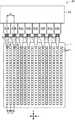
図4は、マイクロプレート4の上面図である。ウェル41は、m行×n列で、所定のピッチでマトリクス配列されている。マイクロプレート4として基準プレートが用いられる場合、その縦×横のサイズは、85.48mm×127.76mmである(ANSI(American National Standards Institute)のSLAS(Society for Laboratory Automation and Screening)によって2004年に規定された「Footprint Dimensions−for Microplates」参照)。この場合、一般的なウェル41の数は、図4に示す通り、m行×n列=24行×16列=384個である。これらウェル41が、マイクロプレート4の基材に所定のピッチでマトリクス配列されている。 FIG. 4 is a top view of the
図5は、複数のチップからマイクロプレートへ細胞の吐出態様を模式的に示す図であって、ヘッド63に装着されたチップの配列ピッチとウェル41の配列ピッチとの関係を示す図である。ここでは、ヘッド本体62に一列に配列された8本のヘッド63A、63B、63C、63D、63E、63F、63G、63Hが備えられ、これらヘッドにチップ6A、6B、6C、6D、6E、6F、6G、6Hが各々装着されているヘッドユニット61を例示している。 FIG. 5 is a diagram schematically showing an ejection mode of cells from a plurality of chips to the microplate, and is a diagram showing a relationship between the array pitch of the chips mounted on the
マイクロプレート4のウェル41が、x方向(行方向)に均等なピッチx1で配列されている。8本のヘッド63A〜63Hにそれぞれ装着されたチップ6A〜6H(各々の先端開口6t)は、x方向に前記ピッチx1の2倍のピッチx2で配列されている。チップ6A〜6Hのピッチx2は、ピッチx1の2倍に限らず、x1のp倍(pは1以上の整数)であれば良い。このようなヘッド63A〜63H(チップ6A〜6H)の配列としておけば、例えばチップ6Aの先端開口6tを、吐出ターゲットとする1つのウェル41と位置合わせすることで、自ずと他のチップ6B〜6Hも、順次x方向の一つ飛ばしのウェル41に各々位置合わせされるようになる。これにより、各チップ6A〜6Hから同時に細胞Cを吐出させ、各ウェル41に細胞Cを注入することができる。このような同時吐出を実行させることで、ヘッドユニット61の移動時間やヘッド63A〜63Hの昇降の回数を減らすことができ、細胞Cの移動に要する時間を短縮することができる。 The
ここで、上記の同時吐出とは、必ずしもチップ6A〜6Hからの細胞Cの吐出が同じタイミングで実行されることに限定されない。つまり、図5のようにウェル41とチップ6A〜6Hとの位置合わせが行われた状態で、全てのチップ6A〜6Hから同じタイミングで細胞Cを吐出させる態様、或いは、チップ6A〜6Hの一部又は全部について異なるタイミングで細胞を吐出させる態様等、ヘッドユニット61の移動を伴わないでチップ6A〜6Hから細胞Cを吐出させる各種態様を、本明細書では「同時吐出」と想定している。 Here, the above simultaneous ejection is not necessarily limited to the ejection of the cells C from the
チップ廃棄部15は、上述の吸引及び吐出動作を終えた使用後のチップ6がヘッド63から回収する部位である。チップ廃棄部15は、使用後のチップ6を収容するチップ回収容器19を含む。前記廃棄の際、使用済のチップ6を装備したヘッドユニット61がチップ回収容器19の開口部上に移動され、ヘッド63からチップ6の取り外し動作が実行される。この取り外し動作により、チップ6は、チップ回収容器19内に落下する。 The
[細胞移動動作の説明]
図1を参照して、細胞移動装置Sによる細胞移動動作について説明する。細胞移動動作の基本的な手順は、(1)ヘッド63へのチップ6の装着、(2)チップ6の先端開口6tの位置較正、(3)選別容器18(ディッシュ2)からの細胞Cのピッキング、(4)マイクロプレート4への細胞Cの移載、(5)チップ6の廃棄、である。これら手順を順次実行するため、ヘッドユニット61はガイドレール64に沿って、細胞移動ライン10の各作業部の上空を左から右へ移動される。カメラユニット5は、上記手順(2)の際に、先端開口6tの位置を求めるためにヘッド63に装着されたチップ6を撮像し、上記手順(3)の前に、使用可能な細胞Cの選定のためにディッシュ2を撮像し、上記手順(4)の後に、移載された細胞Cの確認のためにマイクロプレート4を撮像する。以下、各手順(1)〜(5)を説明する。[Explanation of cell movement]
With reference to FIG. 1, the cell movement operation by the cell movement device S will be described. The basic procedure of the cell transfer operation is (1) mounting the
上記手順(1)では、ヘッドユニット61はチップストック部11上のチップ装着位置P11に移動される。この際、ストック容器16に保持されているチップ6の一つと、ヘッド63の一つとが鉛直軸上で位置合わせされる位置で、ヘッドユニット61は停止される。そして、図1に点線で示すように、前記一つのヘッド63が下降され、当該ヘッドの下端にチューブ状のチップ6の上端部分が嵌合される。しかる後、ヘッド63が上昇される。他のヘッド63についても、同様にしてチップ6が装着される。 In the above procedure (1), the
続く手順(2)の実行のため、ヘッドユニット61はチップ較正部12上のチップ較正位置P12に移動される。この際、チップ6が新たに装着された一つのヘッド63が撮像ピット17の鉛直軸上で位置合わせされる位置で、ヘッドユニット61は停止される。一方、カメラユニット5も、チップ較正部12の撮像ピット17直下のチップ撮像位置P21へ移動される。そして、カメラユニット5により撮像ピット17上に位置するチップ6が撮像される。 In order to execute the subsequent procedure (2), the
先端開口6tの位置は、例えばコントラスト検出方式により求めることができる。具体的には、先端開口6tの下方の所定位置を撮像始点として、カメラレンズ51により数十ミクロン単位でフォーカス位置を上方にシフトさせつつ、カメラユニット5にチップ6の画像を順次撮像させる。撮像終点は、先端開口6tの上方であると確定できる所定位置である。得られた画像の中で、先端開口6tと推定されるラインが最も高いコントラストで写っている画像が撮像されたフォーカス位置を合焦位置と扱い、そのフォーカス距離に基づいて先端開口6tの座標位置が求められる。当該座標位置と、チップ6がヘッド63に正規に装着された場合の基準位置とが比較され、その差分から補正値が導出される。この補正値は、ヘッドユニット61(ヘッド63)の移動制御の際の補正値として利用される。他のヘッド63についても、同様な撮像及び補正値の導出が行われる。 The position of the
上記手順(3)では、ヘッドユニット61は選別部13上の細胞吸引位置P13に移動される。手順(3)の実行の前に、選別容器18内の第1〜第4ディッシュ2A〜2D上に各検体の細胞Cを含む細胞懸濁液が撒かれ、各ディッシュ2A〜2Dに細胞Cが担持される。そして、カメラユニット5が選別部13下のディッシュ撮像位置P22に移動され、細胞Cが担持された各ディッシュ2A〜2Dを撮像する。なお、カメラユニット5の画角はディッシュサイズに比べて小さいので、複数回の撮像が行われる。これらの画像に基づき、使用可能な細胞Cを判定し、その細胞Cが担持された保持凹部3の座標が特定される。そして、どの細胞Cを、どのヘッド63(チップ6)で、どのような順番で吸引させるかの吸引シーケンスが設定される。さらに、どのヘッド63(チップ6)から、マイクロプレート4のどのウェル41に吐出させるかの吐出シーケンスも設定される。
が設定される。In the procedure (3), the
Is set.
吸引シーケンスが設定されたら、手順(2)で得られた補正値を参照して、最初に吸引を行うチップ6と吸引ターゲットとするディッシュ2の保持凹部3との位置合わせが行われ、ヘッド63が下降される。チップ6の先端開口6tが選別容器18内の培地Lに突入し、且つターゲットの保持凹部3に対峙したら、ヘッド63に吸引力が発生される。これにより、ターゲットの保持凹部3に担持されている細胞Cが、チップ6内に吸引される。しかる後、ヘッド63が上昇される。以下、吸引シーケンスに従って、後続のチップ6と対応する保持凹部3とについて、順次上記と同様な動作が行われ、各チップ6に細胞Cが吸引される。 When the suction sequence is set, the position of the
上記手順(4)では、ヘッドユニット61は移載部14上の細胞吐出位置P14に移動される。すなわち、ヘッドユニット61はディッシュ2上からマイクロプレート4上へ移動される。ヘッドユニット61は、細胞Cを保持したチップ6と、吐出ターゲットのマイクロプレート4のウェル41とが鉛直方向に位置合わせされるように停止される。次いで、ヘッド63が、チップ6の先端開口6tがウェル41の開口に入り込むまで、下降される。そして、ヘッド63に吐出力が発生され、先端開口6tからチップ6内に保持されている細胞Cがウェル41へ吐出される。この吐出に際しては、先に図5に基づき説明したように、複数又は全部のヘッド63が同時に下降され、これらヘッド63に装着されたチップ6から同時に細胞Cが吐出される。 In the procedure (4), the
手順(4)では、カメラユニット5も、移載部14下のマイクロプレート撮像位置P23へ移動される。上述のウェル41への細胞Cの吐出が完了した後、カメラユニット5により細胞Cを担持したマイクロプレート4の画像が撮像される。これにより、マイクロプレート4における細胞Cの担持状況を把握することができる。この後、細胞Cを担持したマイクロプレート4は、細胞Cの観察、薬効確認、検査若しくは培養等の各種処理作業に供される。典型例としては、ウェル41に供試化合物が添加され、その反応を観察する実験が行われる。 In step (4), the
上記手順(5)では、ヘッドユニット61はチップ廃棄部15上のチップ廃棄位置P15に移動される。チップ廃棄部15には上面が開口したチップ回収容器19が配置されている。チップ回収容器19に対してヘッド63が下降され、さらにヘッド63内に内蔵されているチップ取り外し用ロッド(図略)が下降される。前記ロッドの下降によりチップ6が押圧され、ヘッド63からチップ6が取り外される。取り外されたチップ6は、チップ回収容器19内に落下する。この取り外し作業は、同じ検体の細胞Cの吸引及び吐出を行う場合は、チップ6の汚染度合いに応じて数回〜10回程度の吸引及び吐出で実行され、異なる検体の吸引及び吐出を行う場合は、検体が変わる度に実行される。 In the procedure (5), the
[検体別の細胞の吸引/吐出の態様]
本実施形態の細胞移動装置Sは、上述の通りの細胞移動動作を行うが、検体が複数存在する場合に、可及的にチップ6の交換作業を少なくすることができる手法を採用している。例えば、第1ディッシュ2A(図2)に第1検体から採取された細胞Cが、第2ディッシュ2Bに第2検体から採取された細胞Cが、各々担持されているとする。第1検体の細胞Cを吸引するために第1ディッシュ2Aの培地Lと接触したチップ6は、汚染の問題が生じるので、もはや第2検体の細胞Cの吸引のため第2ディッシュ2Bの培地Lには接触させることはできない。従って、第2検体の細胞Cの吸引のためには、チップ6の交換作業が必要となる。このような制限下で、本実施形態の細胞移動装置Sよれば、複数種の細胞Cを移動させる際にも、チップ交換作業の回数を抑制乃至は交換不要とすることができる。[Aspiration / Discharge Mode of Cells by Specimen]
The cell transfer device S of the present embodiment performs the cell transfer operation as described above, but employs a method that can reduce the replacement work of the
<比較例>
まず、検体が複数存在する場合における、細胞の吸引/吐出の態様の比較例を、図6に基づいて説明する。ここでは、図5に例示したように、8本のヘッド63A〜63Hが備えられ、これらに各々チップ6A〜6Hが装着されているヘッドユニット61にて、細胞Cの吸引及び吐出が行われるものとする。また、m行×n列=24行×16列のウェル41を具備するマイクロプレート4が用いられるものとする。チップ6A〜6Hの配列ピッチは、ウェル41の行方向のピッチの2倍とする。図6では、8本のチップ6A〜6Hをそれぞれ矢印で簡略化して示し、また、1行分の16個のウェル41を記載している。<Comparative example>
First, a comparative example of a mode of aspirating / discharging cells when a plurality of specimens are present will be described based on FIG. Here, as illustrated in FIG. 5, eight
比較例では、特定の個体に属する検体1の細胞Cと、検体1とは異なる個体に属する検体2の細胞Cとが存在する場合、まず検体1の細胞Cの吸引及び吐出が実行され、続いて検体2の細胞Cの吸引及び吐出が実行される、というように、単純に検体順に吸引及び吐出動作が行われる。 In the comparative example, when the cells C of the
一列に配列された8本のチップ6A〜6Hを用い、1行=16個のウェル41に細胞Cを同時吐出する場合、1行あたり2回の同時吐出動作が行われることになる。まず、例えば第1ディッシュ2Aから、使用可能と判定された検体1の細胞Cが、8本のチップ6A〜6Hにそれぞれ吸引される(1回目の吸引)。そして、ヘッドユニット61がマイクロプレート4まで移動され、チップ6A〜6Hに吸引された細胞Cが、1回目の吐出動作によって、16個のウェル41のうちの8個に吐出される。図6において、ウェル41の□に「1」の数字が記入されていることは、そのウェル41に検体1の細胞Cが吐出されたことを示す(以下、同じ)。つまり、1回目の吐出前は空であった16個のウェル41のうち、1回目の吐出によって一つ飛ばしの8個のウェル41に検体1の細胞Cが担持されることになる。 When eight
続いて、2回目の吸引として、第1ディッシュ2Aから検体1の細胞Cが、8本のチップ6A〜6Hにそれぞれ吸引される。そして、ヘッドユニット61がマイクロプレート4まで移動され、1回目の吐出動作において吐出対象とされなかった残りの8個のウェル41に、チップ6A〜6Hから細胞Cを吐出する2回目の吐出動作が実行される。これにより、1行=16個のウェル41の全てに、検体1の細胞Cが担持される。これと同じ動作が、所要の行数分だけ実行される。 Then, as the second suction, the cells C of the
この後、検体2の細胞Cの吸引及び吐出が実行されることになるが、その前に、チップ6の交換作業が必要となる。この交換作業は、ヘッドユニット61をチップ廃棄部15に移動させて、使用済のチップ6を取り外す作業と、ヘッドユニット61をチップストック部11に移動させて、未使用のチップ6をヘッド63へ装着させる作業と、ヘッドユニット61をチップ較正部12に移動させて、ヘッド63に新たに装着されたチップ6の先端開口6tのXYZ座標を求める作業とを含む。 After that, the suction and discharge of the cells C of the
上記交換作業の後、例えば第2ディッシュ2Bから、1回目の吸引として検体2の細胞Cが8本のチップ6A〜6Hにそれぞれ吸引され、ヘッドユニット61がマイクロプレート4まで移動される。次いで、チップ6A〜6Hに吸引された検体2の細胞Cが、1回目の吐出動作によって、16個のウェル41のうちの8個に吐出される。図6において、ウェル41の□に「2」の数字が記入されたものが、検体2の細胞Cが吐出されたウェル41である。この1回目の吐出によって一つ飛ばしの8個のウェル41に検体2の細胞Cが担持される。そして、2回目の吸引及び2回目の吐出が実行され、1行=16個のウェル41の全てに、検体2の細胞Cが担持される。これと同じ動作が、所要の行数分だけ実行される。他に検体が存在する場合は、上記と同じ動作が繰り返される。 After the replacement work, for example, the cells C of the
図7は、比較例の吐出方法が適用された場合の、マイクロプレート4における細胞Cの担持状況を示す上面図である。検体1の細胞Cが6行×16列のウェル41のグループに担持され、これに隣接する6行×16列のウェル41のグループに検体2の細胞C担持されている。このように細胞Cを担持するマイクロプレート4は、例えば、検体1の細胞Cを担持するウェル41の各々に「化合物A」が注液され、検体2の細胞Cを担持するウェル41の各々に「化合物B」が注液され、これらに対する各細胞Cの感応性を確認する実験等に供される。 FIG. 7 is a top view showing how cells C are carried on the
以上説明した比較例の方法では、異なる検体の細胞Cの吸引及び吐出動作へ移行する度に、上述のチップ6の交換作業が必要となる。当該交換作業には相応の時間を要するため、細胞移動動作を長時間化してしまう。しかも、前記交換作業は処理すべき検体数(細胞種類)が多くなるほど多くなり、多くの時間を要することになる。また、チップ6の廃棄数も増えることになり、コスト面からも好ましくない。さらに、検体1の細胞Cの吐出を終えた後に検体2の細胞Cをディッシュ2に撒くようにした場合、そのための段取り作業が前記交換作業の度に発生することとなり、多くの時間を消費することになる。 In the method of the comparative example described above, the replacement work of the
<実施形態>
次に、検体が複数存在する場合における、細胞の吸引/吐出の態様の第1実施形態を、図8に基づいて説明する。8本のチップ6A〜6Hを具備するヘッドユニット61が用いられる点、24行×16列のウェル41を具備するマイクロプレート4が用いられる点など、条件は上述の比較例と同じである。検体については、検体1〜検体4まで存在し、これら検体1〜4の細胞Cが、それぞれ第1〜第4ディッシュ2A〜2D(図2)に担持されているものとする。<Embodiment>
Next, a first embodiment of a mode of aspirating / discharging cells when a plurality of specimens exist will be described based on FIG. The conditions are the same as those of the above-described comparative example, such that the
本実施形態では、8本のヘッド63A〜63H(チップ6A〜6H)が、各検体1〜4に対して割り当てられる。図8では、チップ6A、6Bが検体1に(第1検体用ヘッド)、チップ6C、6Dが検体2に(第2検体用ヘッド)、チップ6E、6Fが検体3に、チップ6G、6Hが検体4に、各々割り当てられている(指定されている)例を示している。 In this embodiment, eight
1回目の吸引では、チップ6A、6Bは第1ディッシュ2Aにおいて検体1の細胞C、チップ6C、6Dは第2ディッシュ2Bにおいて検体2の細胞C、チップ6E、6Fは第3ディッシュ2Cにおいて検体3の細胞C、チップ6G、6Hは第4ディッシュ2Dにおいて検体4の細胞Cの吸引がそれぞれ行われる。そして、ヘッドユニット61がマイクロプレート4まで移動され、チップ6A〜6Hに吸引された細胞Cが、1回目の吐出動作によって、16個のウェル41のうち、一つ飛ばしの8個のウェル41に各々吐出される。図8に示されているように、この1回目の吐出によってウェル41に担持されるのは、検体1〜検体4の細胞Cの各2個である。 In the first suction, the
続いて、2回目の吸引として、上記と同様にして、第1〜第4ディッシュ2A〜2Dから検体1〜検体4の細胞Cが、8本のチップ6A〜6Hにそれぞれ2個ずつ吸引される。そして、ヘッドユニット61がマイクロプレート4まで移動され、1回目の吐出動作において吐出対象とされなかった残りの8個のウェル41に、チップ6A〜6Hから細胞Cを吐出する2回目の吐出動作が実行される。これにより、1行=16個のウェル41の各4個ずつに、検体1〜検体4の細胞Cがそれぞれ担持される。これと同じ動作が、所要の行数分だけ実行される。このように、検体別にヘッド63を指定し、各々の検体だけに対して吸引及び吐出を行わせることで、細胞移動作業中にチップ6の交換作業を省略若しくは交換回数を大きく減らすことができ、作業時間を短縮することができる。 Subsequently, as the second suction, in the same manner as above, two cells C of the first to
図9は、上記第1実施形態の吐出方法が適用された場合の、マイクロプレート4における細胞Cの担持状況を示す上面図である。検体1の細胞Cは、m1〜m24行×n1〜n4列のウェル41に、検体2の細胞Cは、m1〜m24行×n5〜n8列のウェル41に、検体3の細胞Cは、m1〜m24行×n9〜n12列のウェル41に、検体4の細胞Cは、m1〜m24行×n13〜n16列のウェル41に、それぞれ担持されている。 FIG. 9 is a top view showing how cells C are carried on the
このように細胞Cを担持するマイクロプレート4は、例えば図9に例示しているように、m1〜m6行×n1〜n16列のウェル41の各々に「化合物A」を注液し、m7〜m12行×n1〜n16列のウェル41の各々に「化合物B」を注液し、m13〜m18行×n1〜n16列のウェル41の各々に「化合物C」を注液し、m19〜m24行×n1〜n16列のウェル41の各々に「化合物D」を注液し、これら化合物A〜Dに対する各細胞Cの感応性を確認する実験等に供することができる。 As described above, for example, in the
例えば、検体1〜検体4のそれぞれについて4列ずつウェル41が指定されているので、各列で添加する化合物の濃度を変えるようにすることができる。具体的には、検体1について、1列目のウェル41には最も高濃度の化合物A〜Dを、4列目のウェル41には最も低濃度の化合物A〜Dというように、徐々に化合物濃度を低下させるようなウェル41の使用方法を例示できる。また、化合物A〜Dのそれぞれについて6行ずつウェル41が指定されているが、例えばこれら各行については全く同じ濃度分布とし(同じ濃度組合せを6つ作る)、実験サンプル数を増やすといったウェル41の使用方法を例示できる。 For example, since the
なお、上述したチップ6A〜6Hからマイクロプレート4のウェル41への細胞吐出動作において、化合物A〜Dを細胞吐出後にウェル41へ注液する場合は、チップ6A〜6Hの交換を要しない。一方、化合物A〜Dが予めウェル41へ注液する場合は、複数の吐出動作の間にチップ6A〜6Hの交換を要する。後者の場合、1回目の吐出動作の際に、チップ6A〜6Hがウェル41内の化合物A〜Dと接触することになる。この場合、チップ6A〜6Hを交換せずに2回目の吸引動作を実行させると、第1〜第4ディッシュ2A〜2Dの培地L及び検体1〜検体4が化合物A〜Dの影響を受けてしまうからである。 In the above-described cell discharge operation from the
図10は、第2実施形態に係る細胞の吸引/吐出方法を示す模式図である。ここでは、8つの検体;検体1〜検体8が存在し、チップ6Aが検体1に、チップ6Bが検体2に、チップ6Cが検体3に、チップ6Dが検体4に、チップ6Eが検体5に、チップ6Fが検体6に、チップ6Gが検体7に、チップ6Hが検体8に、各々指定されている例を示している。つまり、8本のヘッド63A〜63Hの各々に一つの検体が指定されている例を示している。 FIG. 10 is a schematic diagram showing a cell suction / discharge method according to the second embodiment. Here, there are eight specimens;
この例では、1回目の吸引では、チップ6A〜6Hの各々が、検体1〜検体8の細胞Cをそれぞれ吸引する。つまり、ヘッドユニット61が、検体1〜検体8の各々を担持するディッシュを巡回し、チップ6Aが検体1の細胞Cを吸引し、チップ6Bが検体2の細胞Cを吸引し、・・・というように、各チップが対象とする検体の細胞Cを順次吸引する。そして、ヘッドユニット61がマイクロプレート4まで移動され、チップ6A〜6Hに吸引された細胞Cが、1回目の吐出動作によって、16個のウェル41のうち、一つ飛ばしの8個のウェル41に各々吐出される。図10に示されているように、この1回目の吐出によってウェル41に担持されるのは、検体1〜検体8の細胞Cの各1個である。 In this example, in the first suction, the
続いて、2回目の吸引として、上記と同様にして各ディッシュから検体1〜検体8の細胞Cが、8本のチップ6A〜6Hにそれぞれ1個ずつ吸引される。そして、ヘッドユニット61がマイクロプレート4まで移動され、1回目の吐出動作において吐出対象とされなかった残りの8個のウェル41に、チップ6A〜6Hから細胞Cを吐出する2回目の吐出動作が実行される。これにより、1行=16個のウェル41の各2個ずつに、検体1〜検体8の細胞Cがそれぞれ担持される。これと同じ動作が、所要の行数分だけ実行される。本例のように検体数が多い場合、比較例の方式を採用するとチップ6の交換作業が多くなって作業時間が長くなり、またチップ6の廃棄数も多量となる。しかし、本実施形態によれば、細胞移動に要する作業時間を短縮し、チップ6のロスも減らすことができる。 Then, as the second suction, cells C of the
図11は、上記第2実施形態の吐出方法が適用された場合の、マイクロプレート4における細胞Cの担持状況を示す上面図である。検体1の細胞Cは、m1〜m24行×n1、n2列のウェル41に、検体2の細胞Cは、m1〜m24行×n3、n4列のウェル41に、検体3の細胞Cは、m1〜m24行×n5、n6列のウェル41に、検体4の細胞Cは、m1〜m24行×n7、n8列のウェル41に、検体5の細胞Cは、m1〜m24行×n9、n10列のウェル41に、検体6の細胞Cは、m1〜m24行×n11、n12列のウェル41に、検体7の細胞Cは、m1〜m24行×n13、n14列のウェル41に、検体8の細胞Cは、m1〜m24行×n15、n16列のウェル41に、それぞれ担持されている。 FIG. 11 is a top view showing how cells C are carried on the
このように細胞Cを担持するマイクロプレート4は、第1実施形態と同様に、m1〜m6行×n1〜n16列のウェル41の各々に「化合物A」を注液し、m7〜m12行×n1〜n16列のウェル41の各々に「化合物B」を注液し、m13〜m18行×n1〜n16列のウェル41の各々に「化合物C」を注液し、m19〜m24行×n1〜n16列のウェル41の各々に「化合物D」を注液し、これら化合物A〜Dに対する各細胞Cの感応性を確認する実験等に供することができる。この第2実施形態によれば、1つのマイクロプレート4で8つの検体に対し、同時に各種の処理を行うことができる。 In this manner, the
[細胞移動装置の電気的構成]
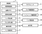
図12は、上記で説明した機能を有する細胞移動装置Sの電気的構成を示すブロック図である。細胞移動装置Sは、ヘッドユニット61(図1)の移動、ヘッド63の位置決め及び昇降、細胞Cの吸引及び吐出のためのヘッド63の吸引力及び吐出力の発生動作、並びにカメラユニット5の動作を制御する制御部7を備える。また、細胞移動装置Sは、カメラユニット5を水平移動させる機構としてカメラ軸駆動部53、ヘッドユニット61を水平移動させる機構としてヘッドユニット軸駆動部65、ヘッド63を昇降させる機構並びに吸引及び吐出動作を行わせる機構としてヘッド駆動部66、及び表示部67を備えている。[Electrical configuration of cell transfer device]
FIG. 12 is a block diagram showing the electrical configuration of the cell transfer device S having the functions described above. The cell transfer device S moves the head unit 61 (FIG. 1), positions and moves the
カメラ軸駆動部53は、ガイドレール52に沿ってカメラユニット5を、チップ撮像位置P21、ディッシュ撮像位置P22及びマイクロプレート撮像位置P23のいずれかへ移動させる駆動モータを含む。好ましい態様は、ガイドレール52に沿ってボールねじが敷設され、該ボールねじに螺合されたナット部材にカメラユニット5が取り付けられ、前記駆動モータが前記ボールねじを正回転又は逆回転させることにより、カメラユニット5を目標位置へ移動させる態様である。 The camera
ヘッドユニット軸駆動部65は、ガイドレール64に沿ってヘッドユニット61(ヘッド本体62)を移動させる駆動モータを含む。好ましい態様は、カメラ軸駆動部53と同様に、ボールねじ及びナット部材を具備し、前記駆動モータが前記ボールねじを正回転又は逆回転させる態様である。なお、ヘッド本体62をXYの2方向に移動させる場合は、ガイドレール64に沿った第1ボールねじ(X方向)と、第1ボールねじに螺合された第1ナット部材に装着された移動板に搭載された第2ボールねじ(Y方向)とを用いる。この場合、ヘッド本体62は第2ボールねじに螺合された第2ナット部材に装着される。 The head unit
ヘッド駆動部66は、先に説明したヘッド63を上下方向に移動させる昇降機構のための動力部、中空ロッドからなるヘッド63の中空部内に組み付けられるピストン機構を駆動するための動力部(例えばモータ)が相当する。上述の通り、昇降機構はヘッド本体62からヘッド63が下方に延び出した下降位置と、ヘッド本体62に大部分が収容された上昇位置との間で、ヘッド63を上下移動させる。ピストン機構の動力部は、ヘッド63内に配置されたピストン部材を昇降させることで、ヘッド63に装着されたチップ6の先端開口6tに、吸引力及び吐出力を発生させる。 The
表示部67は、液晶ディスプレイ等からなり、カメラユニット5により撮影された画像や、制御部7によって画像処理等がなされた画像などを表示する。 The
制御部7は、マイクロコンピュータ等からなり、機能的に、撮像制御部71、画像メモリ72、画像処理部73、ヘッド割当部74、ウェル割当部75、軸制御部76及びヘッド制御部77を備えている。 The
撮像制御部71は、カメラユニット5の撮像動作及び移動動作を制御する。本実施形態では撮像制御部71は、カメラユニット5に、チップ撮像位置P21においてヘッド63に装着されたチップ6の先端開口6tを撮像させる動作、ディッシュ撮像位置P22において細胞Cを担持したディッシュ2を撮像させる動作、及び、マイクロプレート撮像位置P23において細胞Cが移載されたマイクロプレート4を撮像させる動作を制御する。なお、ディッシュ2又はマイクロプレート4の撮像において、カメラユニット5の画角はこれらのサイズに比べて相当に小さいので、撮像制御部71は、カメラ軸駆動部53を制御してカメラユニット5をXY方向に微小移動させつつ、カメラユニット5にディッシュ2又はマイクロプレート4の撮像動作を実行させる。 The image capturing
画像メモリ72は、前記マイクロコンピュータに具備されている記憶領域や外部ストレージ等からなり、カメラユニット5により取得された画像データを一時的に格納する。 The
画像処理部73は、カメラユニット5が撮像し、画像メモリ72に格納された画像データを画像処理する。画像処理部73は、例えば、細胞Cを保持するディッシュ2又はマイクロプレート4の画像に基づき、ディッシュ2又はマイクロプレート4上における細胞Cの存在を画像上で認識する処理、細胞Cの分布を認識する処理、認識された細胞Cの形状を認識する処理などを、画像処理技術を用いて実行する。 The
ヘッド割当部74は、複数の検体の細胞Cが存在する場合に、複数のヘッド63のうち、いずれのヘッド63をどの検体用のヘッドとして用いるかを割り当てる。この割り当てのためにヘッド割当部74は、ヘッド63の各々に対して、いずれの検体の移動のために用いるかを指定する処理を行う。当該指定は、ユーザが指定する検体の数、ヘッド本体62が備えるヘッド63の本数、複数のディッシュからの吸引シーケンス、供試化合物の数等を参照して実行される。例えば、図8に示した通り、検体数=4、ヘッド63(チップ6)の本数=8の場合、ヘッド割当部74は、各検体用に2本ずつのヘッド63を指定する。 The head allocation unit 74 allocates which
ウェル割当部75は、マイクロプレート4のウェル41を、ヘッド割当部74が指定した各検体用ヘッド63のチップ6から各細胞Cを同時吐出が可能なように、各検体用ウェルとして割り当てる。この割り当てのためにウェル割当部75は、ウェル41の各々に対して、いずれの検体の受け入れのために用いるかを指定する処理を行う。例えば図8に例示したようなヘッド指定が設定された場合、ウェル割当部75は、図9に示すように384個のウェル41を、検体1=m1〜m24行×n1〜n4列(第1検体用ウェル)、検体2=m1〜m24行×n5〜n8列(第2検体用ウェル)、検体3=m1〜m24行×n9〜n12列、検体4=m1〜m24行×n13〜n16列、と指定する。これにより、8本のヘッド63で1行当たり2回の同時吐出で、全ウェル41に細胞Cを移載することができる。 The
軸制御部76は、ヘッドユニット軸駆動部65の動作を制御する。すなわち、軸制御部76は、ヘッドユニット軸駆動部65を制御することで、ヘッドユニット61を水平方向の所定の目標位置へ移動させる。ヘッド63(チップ6)の、吸引対象となるディッシュ2の保持凹部3の鉛直上空での位置決め、並びに吐出対象となるマイクロプレート4のウェル41の鉛直上空での位置決め、さらには較正処理時における撮像ピット17上での撮影対象となるチップ6の位置決めは、軸制御部76によるヘッドユニット軸駆動部65の制御によって実現される。 The
ヘッド制御部77は、ヘッド駆動部66を制御する。ヘッド制御部77は、ヘッド駆動部66の前記昇降機構のための動力部を制御することにより、制御対象とするヘッド63を所定の目標位置に向けて昇降させる。また、ヘッド制御部77は、制御対象とするヘッド63についての前記ピストン機構の動力部を制御することにより、所定のタイミングで当該ヘッド63に装着されているチップ6の先端開口6tに吸引力又は吐出力を発生させる。 The
[細胞移動装置の動作フローの説明]
図13は、細胞移動装置Sの動作の一例を示すフローチャートである。ここでは、図1に示すように、図略の分注チップにより各検体の細胞Cを含む細胞懸濁液が選別容器18に注入され、ディッシュ2上に各検体の細胞Cが既に保持されているものとする。制御部7は、ユーザから図略の入力装置を通して、検体数及び実験に供する化合物グループ数の入力を受け付ける(ステップS1)。通常、検体数のMaxは、ヘッド本体62に備えられているヘッド63の本数分である。また、検体数は、ヘッド63の本数で割り切れる数に制限することが望ましい。[Explanation of operation flow of cell transfer device]
FIG. 13 is a flowchart showing an example of the operation of the cell transfer device S. Here, as shown in FIG. 1, a cell suspension containing cells C of each sample is injected into the sorting
ステップS1の入力を受けてヘッド割当部74は、どのヘッド63(チップ6)で、どの検体の細胞Cを吸引/吐出させるかの指定(第1、第2検体用ヘッドの指定)、つまり検体別にヘッド63を指定する処理を行う(ステップS2)。その具体例は、図8、図10に例示した通りである。次いで、ウェル割当部75が、全てのヘッド63のチップ6から細胞Cを同時吐出させることを前提として、どのチップ6からマイクロプレート4のどのウェル41に吐出させるかの指定(第1、第2検体用ウェルの指定)、つまり検体別にウェル41を指定する処理を行う(ステップS3)。その具体例は、図9、図11に例示した通りである。 In response to the input in step S1, the head assigning unit 74 specifies which head 63 (chip 6) should be used to suck / discharge the cell C of which sample (specification of the first and second sample heads), that is, the sample. Separately, a process of designating the
以下、上記で説明した手順(1)〜(5)が実行される。先ず、軸制御部76がヘッドユニット軸駆動部65を制御して、ヘッドユニット61をチップストック部11上のチップ装着位置P11に移動させる。この際、ストック容器16に保持されている未使用のチップ6の一つと、最初に装着が行われるヘッド63とが鉛直軸上で位置合わせされる。その後、軸制御部76はヘッド駆動部66を制御して、前記位置合わせされたヘッド63を下降させ、当該ヘッド63の下端にターゲットのチップ6を装着させる(ステップS4)。他のヘッド63にも、同様にしてチップ6が装着される。 Hereinafter, the procedures (1) to (5) described above are executed. First, the
続いて、チップ6の撮像及び較正処理が行われる。すなわち、軸制御部76がヘッドユニット軸駆動部65を制御して、ヘッドユニット61をチップ較正部12上のチップ較正位置P12に移動させる。この際、チップ6が新たに装着された一つのヘッド63が撮像ピット17の鉛直軸上で位置合わせされる。また、撮像制御部71がカメラ軸駆動部53を制御して、カメラユニット5を撮像ピット17直下のチップ撮像位置P21へ移動させる。その後、ヘッド制御部77がヘッド駆動部66を制御して、撮像対象となるチップ6が装着されたヘッド63を下降させる。また、撮像制御部71は、カメラユニット5にチップ6の先端開口6tの画像を撮像させる。 Then, the imaging and calibration process of the
この撮像は、先端開口6tの下方の所定位置を撮像始点として、数十ミクロン単位でフォーカス位置を上方にシフトさせつつ、カメラユニット5にチップ6の画像を順次撮像させる方式が採られる。そして、例えば上記に例示したようなコントラスト検出方式により、新たにヘッド63に装着されたチップ6の先端開口6tの座標位置が求められる(ステップS5)。その後、上述の通り当該座標位置と基準位置とが比較され、その差分から補正値が導出される。他のヘッド63についても、同様な撮像及び補正値の導出が行われる。 This image pickup uses a method in which the
次に、撮像制御部71がカメラユニット5を選別部13下のディッシュ撮像位置P22に移動させ、カメラユニット5に細胞Cが担持されたディッシュ2(ディッシュ2A〜2D)の画像を撮像させる。取得された画像データは画像メモリ72に一時的に格納され、画像処理部73により実行される前記画像データに対する画像処理により、使用可能な細胞Cの判定処理、及びその使用可能な細胞Cが担持された保持凹部3の座標が特定される(ステップS6)。 Next, the
続いて制御部7は、ヘッド割当部74がステップS2で指定した各検体用ヘッド63(チップ6)に、どのような順番で各細胞Cを吸引させるかの吸引シーケンスを設定する。例えば、図2に示す第1〜第4ディッシュ2A〜2D上に検体1〜検体4の細胞Cが各々担持されている場合、どのような順序で各ディッシュ2A〜2Dに対して吸引動作を行うか、また、各ディッシュ2A〜2Dにおいて、どのような順序でそれぞれの保持凹部3から細胞Cを吸引するか等を、ステップS6で得られた座標データに基づき決定する。さらに制御部7は、ウェル割当部75がステップS3で指定した各検体用ウェル41に対して、どのような順序で各ヘッド63(チップ6)から細胞Cを吐出させるかの吐出シーケンスも設定する(ステップS7)。この吐出シーケンスの設定により、チップ6から同時吐出させる吐出回数pが決まることになる。 Subsequently, the
その後、チップ6による使用可能な細胞Cの吸引処理及び吐出処理が実行される。まず制御部7は、チップ6からの同時吐出の回数である吐出カウンタqをq=1に設定する(ステップS8)。そして、軸制御部76が、ヘッドユニット61を選別部13上の細胞吸引位置P13に移動させる。この際、ステップS5で得られた補正値を参照して、吸引シーケンス最初に吸引を行うチップ6と吸引ターゲットとするディッシュ2の保持凹部3との位置合わせが行われる。ヘッド制御部77がヘッド63を下降させると共に、ヘッド63に吸引力を発生させ、保持凹部3から細胞Cを吸引させる。しかる後、ヘッド制御部77はヘッド63を上昇させる。 After that, the suction process and the discharge process of usable cells C by the
以下、前記吸引シーケンスに従って、次のチップ6と次の保持凹部3との位置合わせ、ヘッド63の下降及び細胞Cの吸引、ヘッド63の上昇が繰り返される。つまり、例えば検体1(第1検体)の細胞Cが検体1用に指定されたヘッド63(第1検体用ヘッド)に装着されたチップ6(第1チップ)により第1ディッシュ2Aから吸引され、次いで検体2(第2検体)の細胞Cが検体2用に指定されたヘッド63(第2検体用ヘッド)に装着されたチップ6(第2チップ)により第2ディッシュ2Bから吸引されるというように、各検体の細胞Cが順次吸引されることになる(ステップS9)。 Thereafter, according to the suction sequence, the alignment of the
続いて軸制御部76が、ヘッドユニット61を移載部14上の細胞吐出位置P14に移動させる。この際、軸制御部76は、ステップS5で得られた補正値を参照して、細胞Cを保持したチップ6と、吐出ターゲットのマイクロプレート4のウェル41との鉛直方向における位置合わせを行う。また、撮像制御部71が、カメラユニット5を移載部14下のマイクロプレート撮像位置P23へ移動させる。 Subsequently, the
その後、ヘッド制御部77が全てのヘッド63を下降させると共に、各ヘッド63に吐出力を発生させ、全チップ6から細胞Cを同時に吐出させる。しかる後、ヘッド制御部77はヘッド63を上昇させる。これにより、検体1の細胞Cを保持するチップ6(第1チップ)から検体1用に指定されたウェル41(第1検体用ウェル)へ当該細胞Cが吐出され、検体2の細胞Cを保持するチップ6(第2チップ)から検体2用に指定されたウェル41(第2検体用ウェル)へ当該細胞Cが吐出されるという同時吐出が実行されるものである(ステップS10)。なお図8、図10の例では、1行当たり同時吐出が2回実行されることになる。なお、同時吐出は、列単位で行わせるようにしても良い。つまり、1つのm行又はn列について、前記同時吐出を1回若しくは複数回実行させるものであれば良い。 After that, the
1サイクルの吸引/吐出処理を終えると、制御部7は吐出カウンタqの値が、設定された吐出回数pに達しているか否かを確認する(ステップS11)。p=qではないとき(ステップS11でNO)、制御部7は吐出カウンタqをインクリメントし(ステップS12)、ステップSpに戻って次の吸引/吐出サイクルを実行させる。一方、p=qに至ったとき(ステップS11でYES)、制御部7はチップ6の廃棄処理を実行させる。もちろん、吸引/吐出サイクルの回数が極めて多い場合やチップ6の汚染が想定されるような場合は、全ての吸引/吐出サイクルが完了する前に、チップ6の廃棄処理を実行させるようにしても良い。 When one cycle of suction / discharge processing is completed, the
前記廃棄処理の際、軸制御部76は、ヘッドユニット61をチップ廃棄部15上のチップ廃棄位置P15に移動させる。そして、ヘッド制御部77がヘッド63を下降させ、さらにヘッド63内に内蔵されているチップ取り外し用ロッド(図略)を下降させることにより、ヘッド63からチップ6を押し出す。押し出されたチップ6は、チップ回収容器19に回収される(ステップS13)。以上で、制御部7は、1枚のマイクロプレート4に対する細胞Cの移動処理を終える。 At the time of the discarding process, the
以上説明した本実施形態に係る細胞移動装置Sによれば、ヘッド割当部74により複数のヘッド63が、各々の検体用ヘッドとして指定されるので、各々のヘッド63に装着されるチップ6は、それぞれ特定の検体の細胞Cのみを吸引及び吐出できる。つまり、例えば検体1の細胞Cの吸引のために第1ディッシュ2Aにアクセスするチップ6は、第2ディッシュ2Bにはアクセスすることはない。このため、ヘッドユニット61によって細胞Cの吸引及び吐出が複数回行われる場合でも、途中でチップ6の交換を行う必要がない。従って、チップ6の交換作業に要する時間を省くことができると共に、チップ6の廃棄数も減らすことができる。さらに、各検体の細胞を各検体用ウェルへ同時吐出させることができるよう、ウェル割当部75によりマイクロプレート4のウェル41が指定されるので、細胞Cの吐出作業を効率良く実行させることができる。 According to the cell migration device S according to the present embodiment described above, since the plurality of
なお、本発明において、各検体の細胞を各検体用ウェルへ、必ずしも同時吐出させなくとも良い。例えば、先ずは検体1の移動用に指定されたヘッド63から検体1の受け入れ用に指定されたウェル41へ吐出を行わせ、次いで検体2の移動用に指定されたヘッド63から検体2の受け入れ用に指定されたウェル41へ吐出を行わせるというような細胞Cの吐出作業としても良い。 In the present invention, the cells of each sample do not necessarily have to be ejected simultaneously into each sample well. For example, first, the
S 細胞移動装置
11 チップストック部
12 チップ較正部
13 選別部
14 移載部
15 チップ廃棄部
2 ディッシュ(ディッシュ群)
2A 第1ディッシュ
2B 第2ディッシュ
2C 第3ディッシュ
2D 第4ディッシュ
3 保持凹部(保持部)
4 マイクロプレート
41 ウェル
6 チップ
6t 先端開口
61 ヘッドユニット
63 ヘッド
7 制御部
74 ヘッド割当部
75 ウェル割当部
S
2A 1st dish 2B 2nd dish 2C
4
Claims (4)
Translated fromJapanese前記細胞を受け入れる複数のウェルを有するマイクロプレートと、
吸引力及び吐出力を発生可能な複数のヘッドと、これらヘッドの各々に装着され前記細胞の吸引及び吐出を行うチップとを備え、前記ディッシュ群と前記マイクロプレートとの間を移動可能なヘッドユニットと、
前記ヘッドの吸引力及び吐出力の発生を制御すると共に、前記ヘッドユニットの移動を制御する制御部と、を備え、
前記マイクロプレートの前記ウェルは、m行×n列(m、nは1以上の整数)に配列されており、
前記複数のヘッドは、前記ウェルのm行の配列ピッチのp倍(pは1以上の整数)で一列に配列されており、
前記制御部は、
前記複数のヘッドの少なくとも一部を、前記第1検体の移動のために用いられる第1検体用ヘッドと、前記第2検体の移動のために用いられる第2検体用ヘッドとに指定する処理と、
前記複数のウェルの少なくとも一部を、前記第1検体の受け入れのために用いられる第1検体用ウェルと、前記第2検体の受け入れのために用いられる第2検体用ウェルとに指定する処理であって、1つの行に複数の前記第1及び第2検体用ウェルが含まれるように指定する処理と、
前記第1検体の細胞を前記第1検体用ヘッドに装着された第1チップにより第1ディッシュから、次いで前記第2検体の細胞を前記第2検体用ヘッドに装着された第2チップにより第2ディッシュから、順次吸引させる吸引処理と、
前記1つの行につき、前記第1チップから前記第1検体の細胞を前記第1検体用ウェルへ、前記第2チップから前記第2検体の細胞を前記第2検体用ウェルへ、それぞれ吐出させる吐出処理と、
を実行することを特徴とする細胞移動装置。A dish group having a plurality of holding parts that respectively hold cells to be moved, and a first dish that holds the cells of the first sample and a second dish that holds the cells of the second sample;
A microplate having a plurality of wells for receiving the cells,
A head unit including a plurality of heads capable of generating suction force and discharge force, and a chip attached to each of these heads for suctioning and discharging the cells, and a head unit movable between the dish group and the microplate When,
A control unit that controls the generation of the suction force and the discharge force of the head, and controls the movement of the head unit,
The wells of the microplate are arranged in m rows × n columns(m and n are integers of 1 or more) ,
The plurality of heads are arranged in a line at ap times an arrangement pitch of m rows of the well (p is an integer of 1 or more),
The control unit is
A process of designating at least a part of the plurality of heads as a first sample head used for moving the first sample and a second sample head used for moving the second sample; ,
In a process of designating at least a part of the plurality of wells as a first sample well used for receiving the first sample and a second sample well used for receiving the second sample. And a process of designating that one row includes a plurality of the first and second sample wells,
The cells of the first sample are discharged from the first dish by the first chip mounted on the head for the first sample, and the cells of the second sample are then sampled by the second chip mounted on the head for the second sample. From the dish, the suction process that sucks sequentially,
Discharge for discharging cells of the first sample from the first chip to the well for the first sample and cells of the second sample from the second chip to the well for the second sample for each row. Processing and
A cell migration device, characterized in that
前記制御部は、
前記第1検体用ヘッドに装着された前記第1チップと、前記第2検体用ヘッドに装着された前記第2チップとから同時吐出が可能なように、第1検体用ウェルと第2検体用ウェルとを指定し、
前記吐出処理において、前記第1チップの前記第1検体の細胞と、前記第2チップの前記第2検体の細胞とを同時吐出させる、細胞移動装置。The cell migration device according to claim 1,
The control unit is
A first sample well and a second sample well for simultaneous ejection from the first chip mounted on the first sample head and the second chip mounted on the second sample head. Specify the well and
A cell transfer device which simultaneously ejects cells of the first specimen of the first chip and cells of the second specimen of the second chip in the ejection processing.
未使用の前記チップをストックするチップストック部と、
前記ヘッドに装着された前記チップの先端開口の位置を求めるチップ較正部と、をさらに備え、
前記制御部は、前記吸引処理の前に、
前記ヘッドユニットを前記チップストック部へ移動させると共に、前記ヘッドに未使用の前記チップを装着させる制御と、
前記ヘッドユニットを前記チップ較正部へ移動させると共に、前記ヘッドに新たに装着された前記チップの先端開口の位置を求めさせる制御と、
を実行する細胞移動装置。The cell migration device according toclaim 1 or 2 ,
A chip stock part that stocks the unused chips,
A chip calibration unit for determining the position of the tip opening of the chip mounted on the head;
The control unit, before the suction processing,
Control of moving the head unit to the chip stock portion and mounting the unused chip on the head,
Control for moving the head unit to the chip calibrating unit and determining the position of the tip opening of the chip newly attached to the head,
A cell transfer device for performing.
使用後の前記チップを前記ヘッドから回収するチップ廃棄部をさらに備える、細胞移動装置。The cell migration device according to any one ofclaims 1 to 3 ,
The cell transfer device further comprising a chip discarding unit that collects the used chip from the head.
Priority Applications (5)
| Application Number | Priority Date | Filing Date | Title |
|---|---|---|---|
| JP2016204575AJP6694796B2 (en) | 2016-10-18 | 2016-10-18 | Cell transfer device |
| EP17861674.4AEP3524667A4 (en) | 2016-10-18 | 2017-09-06 | Cell transfer apparatus |
| CN201780063224.9ACN109844090A (en) | 2016-10-18 | 2017-09-06 | Cell mobile device |
| US16/341,435US20200040295A1 (en) | 2016-10-18 | 2017-09-06 | Cell transfer apparatus |
| PCT/JP2017/032059WO2018074086A1 (en) | 2016-10-18 | 2017-09-06 | Cell transfer apparatus |
Applications Claiming Priority (1)
| Application Number | Priority Date | Filing Date | Title |
|---|---|---|---|
| JP2016204575AJP6694796B2 (en) | 2016-10-18 | 2016-10-18 | Cell transfer device |
Publications (2)
| Publication Number | Publication Date |
|---|---|
| JP2018064491A JP2018064491A (en) | 2018-04-26 |
| JP6694796B2true JP6694796B2 (en) | 2020-05-20 |
Family
ID=62019150
Family Applications (1)
| Application Number | Title | Priority Date | Filing Date |
|---|---|---|---|
| JP2016204575AActiveJP6694796B2 (en) | 2016-10-18 | 2016-10-18 | Cell transfer device |
Country Status (5)
| Country | Link |
|---|---|
| US (1) | US20200040295A1 (en) |
| EP (1) | EP3524667A4 (en) |
| JP (1) | JP6694796B2 (en) |
| CN (1) | CN109844090A (en) |
| WO (1) | WO2018074086A1 (en) |
Families Citing this family (3)
| Publication number | Priority date | Publication date | Assignee | Title |
|---|---|---|---|---|
| WO2021019625A1 (en)* | 2019-07-26 | 2021-02-04 | 株式会社島津製作所 | Cell picking device |
| JP2022084356A (en)* | 2020-11-26 | 2022-06-07 | 株式会社島津製作所 | Cell picking device and cell picking method |
| JP7725913B2 (en)* | 2021-07-28 | 2025-08-20 | 横河電機株式会社 | Cell suction support system |
Family Cites Families (10)
| Publication number | Priority date | Publication date | Assignee | Title |
|---|---|---|---|---|
| US7776584B2 (en)* | 2003-08-01 | 2010-08-17 | Genetix Limited | Animal cell colony picking apparatus and method |
| CN101416064B (en)* | 2006-03-28 | 2012-08-22 | 环球生物研究株式会社 | Micro plate treating device and micro plate treating method |
| US20110217725A1 (en)* | 2008-10-24 | 2011-09-08 | Kuraray Co., Ltd. | Cell culture kit, screening method, and method of manufacturing cell culture kit |
| KR101420094B1 (en)* | 2010-10-27 | 2014-07-17 | (주)바이오니아 | Automatic realtime PCR system for the various analysis of biological sample, method for Automatic nucleic acid purification and realtime quantification of gene amplification, method for automatic viable cell count of pathogenic bacteria using realtime quantitative PCR, method for automatically getting antigene density using quantitative immunity PCR |
| KR101762295B1 (en)* | 2012-02-10 | 2017-08-04 | (주)바이오니아 | Automatic analysis apparatus and method of biological samples |
| JP6495281B2 (en)* | 2013-08-12 | 2019-04-03 | インビボサイエンシーズ インコーポレイテッド | Automated cell culture system and method |
| CA2933017C (en)* | 2013-12-12 | 2019-05-21 | Yamaha Hatsudoki Kabushiki Kaisha | A moving apparatus for moving a subject using tips |
| EP3159396B1 (en)* | 2014-06-17 | 2019-12-18 | Yamaha Hatsudoki Kabushiki Kaisha | Object moving device |
| WO2016002066A1 (en)* | 2014-07-04 | 2016-01-07 | ヤマハ発動機株式会社 | Object moving device |
| US10138452B2 (en)* | 2014-08-05 | 2018-11-27 | Yamaha Hatsudoki Kabushiki Kaisha | Object-holding device |
- 2016
- 2016-10-18JPJP2016204575Apatent/JP6694796B2/enactiveActive
- 2017
- 2017-09-06EPEP17861674.4Apatent/EP3524667A4/ennot_activeWithdrawn
- 2017-09-06USUS16/341,435patent/US20200040295A1/ennot_activeAbandoned
- 2017-09-06WOPCT/JP2017/032059patent/WO2018074086A1/ennot_activeCeased
- 2017-09-06CNCN201780063224.9Apatent/CN109844090A/enactivePending
Also Published As
| Publication number | Publication date |
|---|---|
| CN109844090A (en) | 2019-06-04 |
| EP3524667A1 (en) | 2019-08-14 |
| JP2018064491A (en) | 2018-04-26 |
| US20200040295A1 (en) | 2020-02-06 |
| EP3524667A4 (en) | 2019-08-14 |
| WO2018074086A1 (en) | 2018-04-26 |
Similar Documents
| Publication | Publication Date | Title |
|---|---|---|
| DE602004010578T3 (en) | Apparatus and method for housing animal cell colonies | |
| JP6883648B2 (en) | Cell handling device | |
| JP6793244B2 (en) | Imaging system | |
| WO2017110005A1 (en) | Target object pick-up method | |
| JP6694796B2 (en) | Cell transfer device | |
| JPWO2018193719A1 (en) | Cell migration device and cell migration method | |
| CN104011196A (en) | Object Selecting Device And Object Selecting Method | |
| JP6913184B2 (en) | Biological object processing device | |
| JP6853880B2 (en) | Cell migration method and cell migration device | |
| WO2019150756A1 (en) | Movement method and movement device for biological subject | |
| JP6710772B2 (en) | Cell transfer device and cell transfer method | |
| EP3739036B1 (en) | Biological subject transfer device | |
| WO2025037480A1 (en) | Cell movement device and method | |
| WO2023233464A1 (en) | Cell transfer apparatus | |
| JP6735207B2 (en) | Cell imaging method |
Legal Events
| Date | Code | Title | Description |
|---|---|---|---|
| A621 | Written request for application examination | Free format text:JAPANESE INTERMEDIATE CODE: A621 Effective date:20190111 | |
| A131 | Notification of reasons for refusal | Free format text:JAPANESE INTERMEDIATE CODE: A131 Effective date:20191210 | |
| A521 | Request for written amendment filed | Free format text:JAPANESE INTERMEDIATE CODE: A523 Effective date:20200121 | |
| A131 | Notification of reasons for refusal | Free format text:JAPANESE INTERMEDIATE CODE: A131 Effective date:20200204 | |
| A521 | Request for written amendment filed | Free format text:JAPANESE INTERMEDIATE CODE: A523 Effective date:20200312 | |
| TRDD | Decision of grant or rejection written | ||
| A01 | Written decision to grant a patent or to grant a registration (utility model) | Free format text:JAPANESE INTERMEDIATE CODE: A01 Effective date:20200331 | |
| A61 | First payment of annual fees (during grant procedure) | Free format text:JAPANESE INTERMEDIATE CODE: A61 Effective date:20200420 | |
| R150 | Certificate of patent or registration of utility model | Ref document number:6694796 Country of ref document:JP Free format text:JAPANESE INTERMEDIATE CODE: R150 | |
| R250 | Receipt of annual fees | Free format text:JAPANESE INTERMEDIATE CODE: R250 | |
| R250 | Receipt of annual fees | Free format text:JAPANESE INTERMEDIATE CODE: R250 | |
| R250 | Receipt of annual fees | Free format text:JAPANESE INTERMEDIATE CODE: R250 |