JP6693594B2 - Head-up display, control method, program, and storage medium - Google Patents
Head-up display, control method, program, and storage mediumDownload PDFInfo
- Publication number
- JP6693594B2 JP6693594B2JP2019115444AJP2019115444AJP6693594B2JP 6693594 B2JP6693594 B2JP 6693594B2JP 2019115444 AJP2019115444 AJP 2019115444AJP 2019115444 AJP2019115444 AJP 2019115444AJP 6693594 B2JP6693594 B2JP 6693594B2
- Authority
- JP
- Japan
- Prior art keywords
- light
- image
- display
- front window
- vehicle
- Prior art date
- Legal status (The legal status is an assumption and is not a legal conclusion. Google has not performed a legal analysis and makes no representation as to the accuracy of the status listed.)
- Expired - Fee Related
Links
- 238000000034methodMethods0.000titleclaimsdescription9
- 230000010287polarizationEffects0.000claimsdescription34
- 230000003287optical effectEffects0.000claimsdescription13
- 238000012986modificationMethods0.000description11
- 230000004048modificationEffects0.000description11
- 238000002834transmittanceMethods0.000description7
- 238000004891communicationMethods0.000description6
- 238000001514detection methodMethods0.000description6
- 238000010586diagramMethods0.000description6
- 230000006870functionEffects0.000description6
- 238000012545processingMethods0.000description6
- 230000007423decreaseEffects0.000description3
- 230000000694effectsEffects0.000description3
- 239000004973liquid crystal related substanceSubstances0.000description2
- 230000000903blocking effectEffects0.000description1
- 239000000470constituentSubstances0.000description1
- 238000002474experimental methodMethods0.000description1
- 230000004313glareEffects0.000description1
- 230000000007visual effectEffects0.000description1
Images


Landscapes
- Instrument Panels (AREA)
Description
Translated fromJapanese本発明は、ヘッドアップディスプレイの表示の視認性を向上させる技術に関する。 The present invention relates to a technique for improving the visibility of a head-up display.
従来から、ヘッドアップディスプレイにおいて、投影部からの射出光の偏光方向を調整することで、虚像の視認性を向上させる技術が存在する。例えば、特許文献1には、偏光サングラス着用によって虚像を明瞭に視認できない場合に、虚像観察者のマニュアル操作に基づき、位相差板を光路上に配置することで、偏光サングラスでの透過率が向上する方向に偏光方向を変更させることが可能なヘッドアップディスプレイが開示されている。 Conventionally, in a head-up display, there is a technique for improving the visibility of a virtual image by adjusting the polarization direction of light emitted from a projection unit. For example, in
一般に、フロントウィンドウを介して虚像を視認させるヘッドアップディスプレイの場合、フロントウィンドウに入射する光の偏光方向によってフロントウィンドウでの反射率が異なり、これによって虚像の見た目上の輝度が変わる。また、フロントウィンドウは車種等によって形状や傾きが異なるため、車両ごとに最適な光の偏光方向は異なる。この点について、特許文献1は、何ら開示していない。 Generally, in the case of a head-up display in which a virtual image is visually recognized through the front window, the reflectance of the front window varies depending on the polarization direction of light incident on the front window, which changes the apparent brightness of the virtual image. Further, since the shape and the inclination of the front window are different depending on the vehicle type and the like, the optimal polarization direction of light is different for each vehicle. Regarding this point,
本発明は、上記のような課題を解決するためになされたものであり、虚像の視認性を好適に向上させることが可能なヘッドアップディスプレイを提供することを主な目的とする。 The present invention has been made to solve the above problems, and a main object of the present invention is to provide a head-up display capable of suitably improving the visibility of a virtual image.
請求項1に記載の発明は、車両のフロントウィンドウの反射面に画像を構成する光を投射するヘッドアップディスプレイであって、前記光を射出する光源と前期反射面との間の光路上に配置され、前記光の偏光面を回転させる位相変更手段と、前記位相変更手段の回転角度を制御する制御手段と、を備え、前記制御手段は、前記画像の表示位置に関する情報に基づき、前記画像を構成する光が前記反射面で反射する位置での前記フロントウィンドウの湾曲状態を認識し、当該湾曲状態に基づいて、前記画像を構成する光の前記反射面での反射率が向上する方向に前記偏光面を回転させるべく前記位相変更手段を制御することを特徴とする。
The invention according to
また、請求項2に記載の発明は、車両のフロントウィンドウの反射面に画像を構成する光を投射するヘッドアップディスプレイが実行する制御方法であって、前記光を射出する光源と前期反射面との間の光路上に配置され、前記光の偏光面を回転させる位相変更工程と、前記車両の車両情報を取得する取得工程と、前記位相変更工程の回転角度を制御する制御工程と、を有し、前記制御工程は、前記画像の表示位置に関する情報に基づき、前記画像を構成する光が前記反射面で反射する位置での前記フロントウィンドウの湾曲状態を認識し、当該湾曲状態に基づいて、前記画像を構成する光の前記反射面での反射率が向上する方向に前記偏光面を回転するように制御することを特徴とする。
The invention according to claim2is a control method executed by a head-up display that projects light forming an image on a reflective surface of a front window of avehicle, wherein a light source that emits the light and a previous reflective surface are provided. A phase changing step of rotating the polarization plane of the light, an acquisition step of acquiring vehicle information of the vehicle, and a control step of controlling a rotation angle of the phase changing step. However, the control step, based on the information about the display position of the image, to recognize the curved state of the front window at the position where the light forming the image is reflected by the reflective surface, based on the curved state, The polarization plane is controlled so as to rotate in a direction in which the reflectance of the light forming the image on the reflection plane is improved .
また、請求項3に記載の発明は、車両のフロントウィンドウの反射面に画像を構成する光を投射するヘッドアップディスプレイを制御するコンピュータが実行するプログラムであって、前記光を射出する光源と前期反射面との間の光路上に配置され、前記光の偏光面を回転させる位相変更手段と、前記位相変更手段の回転角度を制御する制御手段、として前記コンピュータを機能させ、前記制御手段は、前記画像の表示位置に関する情報に基づき、前記画像を構成する光が前記反射面で反射する位置での前記フロントウィンドウの湾曲状態を認識し、当該湾曲状態に基づいて、前記画像を構成する光の前記反射面での反射率が向上する方向に前記偏光面を回転させるべく前記位相変更手段を制御する。
According to athird aspect of the present invention, there is provideda program executed by a computer that controls a head-up display that projects light that forms an image on a reflective surface of a front window of avehicle. Arranged on the optical path between the reflection surface, the phase changing means for rotating the polarization plane of the light, and the control means for controlling the rotation angle of the phase changing means, to function the computer, the control means, Based on the information about the display position of the image, the curved state of the front window at the position where the light forming the image is reflected by the reflecting surface is recognized, and the light forming the image is recognized based on the curved state. The phase changing means is controlled to rotate the polarization plane in a direction in which the reflectance on the reflection surface is improved.
本発明の1つの好適な実施形態では、車両に設置され、光源から射出された画像を構成する光をフロントウィンドウの反射面で反射させることにより、前記画像を前記車両の室内から視認可能に表示するヘッドアップディスプレイであって、前記光源から射出された光の偏光面を回転させる位相差板と、前記車両の車両情報を取得する取得手段と、前記位相差板の回転角度を制御する制御手段と、を備え、前記位相差板は、前記光源と前記車両のフロントウィンドウの前記反射面との間の光路上に配置され、前記制御手段は、前記取得手段により取得された前記車両情報に基づいて、前記画像を構成する光の前記反射面での反射率が向上する方向に前記位相差板を回転させる。 In a preferred embodiment of the present invention, the image which is installed in a vehicle and which is emitted from a light source and which constitutes an image is reflected by a reflecting surface of a front window so that the image is displayed in a visible manner from the inside of the vehicle. Which is a head-up display, a retardation plate for rotating a polarization plane of light emitted from the light source, an acquisition unit for acquiring vehicle information of the vehicle, and a control unit for controlling a rotation angle of the retardation plate. And the phase difference plate is arranged on an optical path between the light source and the reflection surface of the front window of the vehicle, and the control means is based on the vehicle information acquired by the acquisition means. Then, the retardation film is rotated in a direction in which the reflectance of the light forming the image on the reflection surface is improved.
上記ヘッドアップディスプレイは、車両に設置され、光源から射出された画像を構成する光をフロントウィンドウの反射面で反射させることにより、画像を車両の室内から視認可能に表示する。ここで、上記「画像」は、虚像として表示される。ヘッドアップディスプレイは、位相差板と、取得手段と、制御手段とを備える。位相差板は、光源と車両のフロントウィンドウの反射面との間の光路上に配置され、光源から射出された光の偏光面を回転させる。取得手段は、車両の車両情報を取得する。制御部は、位相差板の回転角度を制御する。ここで、制御部は、取得手段により取得された車両情報に基づいて、画像を構成する光の反射面での反射率が向上する方向に位相差板を回転させる。この態様では、ヘッドアップディスプレイは、車種等によってフロントウィンドウの形状や傾きが異なることを勘案し、車両情報に基づいて、位相差板を回転させる。これにより、ヘッドアップディスプレイは、フロントウィンドウの反射面での画像を構成する光の反射率を高くし、画像の視認性を好適に向上させることができる。 The head-up display is installed in a vehicle and reflects an image of light emitted from a light source, which constitutes an image, on a reflection surface of a front window, so that the image can be visually displayed from inside the vehicle. Here, the "image" is displayed as a virtual image. The head-up display includes a retardation plate, an acquisition unit, and a control unit. The retardation plate is arranged on the optical path between the light source and the reflection surface of the front window of the vehicle, and rotates the polarization plane of the light emitted from the light source. The acquisition means acquires vehicle information of the vehicle. The control unit controls the rotation angle of the retardation plate. Here, the control unit rotates the phase difference plate in a direction in which the reflectance of the reflection surface of the light forming the image is improved, based on the vehicle information acquired by the acquisition unit. In this aspect, the head-up display rotates the retardation plate based on the vehicle information, considering that the shape and inclination of the front window are different depending on the vehicle type and the like. Thereby, the head-up display can increase the reflectance of the light forming the image on the reflecting surface of the front window, and can appropriately improve the visibility of the image.
上記ヘッドアップディスプレイの一態様では、前記制御手段は、前記取得手段により取得された前記車両情報が示すフロントウィンドウの取り付け角度、及び/又は湾曲状態に基づいて、前記画像を構成する光の前記反射面での反射率が向上する方向に前記位相差板を回転させる。この態様により、ヘッドアップディスプレイは、フロントウィンドウの取り付け角度及び/又は湾曲状態を勘案し、フロントウィンドウの反射面での画像を構成する光の反射率が向上する方向に、位相差板を好適に回転させることができる。 In one aspect of the head-up display, the control unit may reflect the reflection of light forming the image based on a mounting angle of a windshield and / or a curved state indicated by the vehicle information acquired by the acquisition unit. The retardation plate is rotated in the direction in which the reflectance on the surface is improved. According to this aspect, in the head-up display, the retardation plate is preferably arranged in the direction in which the reflectance of the light forming the image on the reflective surface of the front window is improved in consideration of the attachment angle and / or the curved state of the front window. It can be rotated.
上記ヘッドアップディスプレイの他の一態様では、前記制御手段は、前記画像の表示位置に関する情報に基づき、前記画像を構成する光が前記反射面で反射する位置での前記フロントウィンドウの湾曲状態を認識し、当該湾曲状態に基づいて、前記画像を構成する光の前記反射面での反射率が向上する方向に前記位相差板を回転させる。この態様によれば、表示する内容等に応じて画像の表示位置が異なる場合であっても、画像を構成する光の照射位置でのフロントウィンドウの湾曲状態に応じて画像を構成する光の偏光方向を調整し、反射面での反射率を好適に向上させることができる。 In another aspect of the head-up display, the control unit recognizes a curved state of the front window at a position where light forming the image is reflected by the reflecting surface, based on information about a display position of the image. Then, based on the curved state, the retardation plate is rotated in a direction in which the reflectance of the light forming the image on the reflection surface is improved. According to this aspect, even when the display position of the image differs depending on the displayed content, the polarization of the light forming the image according to the curved state of the front window at the irradiation position of the light forming the image. By adjusting the direction, the reflectance on the reflecting surface can be suitably improved.
上記ヘッドアップディスプレイの他の一態様では、ヘッドアップディスプレイは、前記車両の画像観察者のサングラスの着用の有無を判断する判断手段を更に備え、前記制御手段は、前記判断手段により前記画像観察者がサングラス着用有りと判断された場合、前記画像を構成する光の前記サングラスでの透過率が向上する方向に前記位相差板を回転させ、前記制御手段は、前記判断手段により前記画像観察者がサングラス着用無しと判断された場合、前記車両情報に基づいて前記画像を構成する光の前記反射面での反射率が向上する方向に前記位相差板を回転させる。この態様によれば、ヘッドアップディスプレイは、画像観察者のサングラス着用の有無に応じて、画像を構成する光の偏光方向を調整し、サングラスの着用時と非着用時のいずれにおいても画像を明確に視認させることができる。 In another aspect of the head-up display, the head-up display further includes a determination unit that determines whether or not the image viewer of the vehicle wears sunglasses, and the control unit causes the image viewer to perform the determination. When it is determined that sunglasses are worn, the phase difference plate is rotated in a direction in which the transmittance of light forming the image in the sunglasses is improved, and the control unit causes the image observer to determine by the determination unit. When it is determined that the sunglasses are not worn, the phase difference plate is rotated in the direction in which the reflectance of the light forming the image on the reflecting surface is improved based on the vehicle information. According to this aspect, the head-up display adjusts the polarization direction of the light forming the image according to whether or not the image observer wears sunglasses, and clears the image whether the sunglasses are worn or not. Can be visually confirmed.
上記ヘッドアップディスプレイの他の一態様では、ヘッドアップディスプレイは、前記車両の周囲の明るさを検知する検知手段を更に備え、前記制御手段は、前記検知手段により検知された前記車両の周囲の明るさが所定の明るさ以下の場合に、前記車両の周囲の明るさが暗くなるほど、前記画像を構成する光の前記反射面での反射率が低下する方向に前記位相差板を回転させる。この態様によれば、ヘッドアップディスプレイは、前記車両の周囲の明るさに応じて、画像が見やすいように、画像の見た目上の輝度を好適に調整することができる。 In another aspect of the head-up display, the head-up display further includes a detection unit that detects the brightness of the surroundings of the vehicle, and the control unit includes the brightness of the surroundings of the vehicle detected by the detection unit. Is less than or equal to a predetermined brightness, the retardation plate is rotated in a direction in which the reflectance of the light forming the image on the reflective surface decreases as the brightness around the vehicle decreases. According to this aspect, the head-up display can appropriately adjust the apparent brightness of the image according to the brightness of the surroundings of the vehicle so that the image can be easily viewed.
本発明の他の好適な実施形態では、車両に設置され、光源から射出された画像を構成する光をフロントウィンドウの反射面で反射させることにより、前記画像を前記車両の室内から視認可能に表示し、前記光源から射出された光の偏光面を回転させる位相差板を備えるヘッドアップディスプレイが実行する制御方法であって、前記車両の車両情報を取得する取得工程と、前記位相差板の回転角度を制御する制御工程と、を有し、前記位相差板は、前記光源と前記車両のフロントウィンドウの前記反射面との間の光路上に配置され、前記制御工程は、前記取得工程により取得された前記車両情報に基づいて、前記画像を構成する光の前記反射面での反射率が向上する方向に前記位相差板を回転させる。ヘッドアップディスプレイは、この制御方法を実行することで、フロントウィンドウの反射面での画像を構成する光の反射率を高くし、画像の視認性を好適に向上させることができる。 In another preferred embodiment of the present invention, the image which is installed in a vehicle and which is emitted from a light source and which constitutes an image is reflected by a reflecting surface of a front window so that the image is displayed in a visible manner from inside the vehicle. And a control method executed by a head-up display including a retardation plate that rotates a plane of polarization of light emitted from the light source, the obtaining step of obtaining vehicle information of the vehicle, and the rotation of the retardation plate. A control step of controlling an angle, wherein the retardation plate is arranged on an optical path between the light source and the reflection surface of the front window of the vehicle, and the control step is acquired by the acquisition step. Based on the vehicle information thus obtained, the retardation plate is rotated in a direction in which the reflectance of the light forming the image on the reflecting surface is improved. By executing this control method, the head-up display can increase the reflectance of the light forming the image on the reflective surface of the front window and can appropriately improve the visibility of the image.
本発明の他の好適な実施形態では、車両に設置され、光源から射出された画像を構成する光をフロントウィンドウの反射面で反射させることにより、前記画像を前記車両の室内から視認可能に表示し、前記光源から射出された光の偏光面を回転させる位相差板を備えるヘッドアップディスプレイを制御するコンピュータが実行するプログラムであって、前記車両の車両情報を取得する取得手段と、前記位相差板の回転角度を制御する制御手段として前記コンピュータを機能させ、前記位相差板は、前記光源と前記車両のフロントウィンドウの前記反射面との間の光路上に配置され、前記制御手段は、前記取得手段により取得された前記車両情報に基づいて、前記画像を構成する光の前記反射面での反射率が向上する方向に前記位相差板を回転させる。コンピュータは、このプログラムを実行することで、フロントウィンドウの反射面での画像を構成する光の反射率を高くし、画像の視認性を好適に向上させることができる。好適には、上記プログラムは、記憶媒体に記憶される。 In another preferred embodiment of the present invention, the image which is installed in a vehicle and which is emitted from a light source and which constitutes an image is reflected by a reflecting surface of a front window so that the image is displayed in a visible manner from inside the vehicle. And a program executed by a computer that controls a head-up display including a retardation plate that rotates a plane of polarization of light emitted from the light source, the acquisition means acquiring vehicle information of the vehicle, and the phase difference. The computer is caused to function as control means for controlling the rotation angle of the plate, the retardation plate is arranged on an optical path between the light source and the reflection surface of the front window of the vehicle, and the control means is Based on the vehicle information acquired by the acquisition unit, the phase difference plate is rotated in a direction in which the reflectance of the light forming the image on the reflection surface is improved. To. By executing this program, the computer can increase the reflectance of the light forming the image on the reflection surface of the front window and can appropriately improve the visibility of the image. Preferably, the program is stored in a storage medium.
以下、図面を参照して本発明の好適な第1〜第3実施例について説明する。 Hereinafter, preferred first to third embodiments of the present invention will be described with reference to the drawings.
<第1実施例>
[概略構成]
図1は、第1実施例に係るヘッドアップディスプレイシステムの概略構成を示す。図1に示すように、本実施例に係るヘッドアップディスプレイシステムは、主に、光源ユニット4と、位相差板5と、凹面鏡8と、を備え、フロントウィンドウ25と、天井部27と、ボンネット28と、ダッシュボード29とを備える車両Veに取り付けられる。<First embodiment>
[Schematic configuration]
FIG. 1 shows a schematic configuration of a head-up display system according to the first embodiment. As shown in FIG. 1, the head-up display system according to the present embodiment mainly includes a
光源ユニット4は、ダッシュボード29内に設けられ、現在地を含む地図情報や経路案内情報、走行速度、その他運転を補助する情報を示す表示像を構成する光(単に「表示光」とも呼ぶ。)を、ダッシュボード29内に設けられた凹面鏡8に向けて射出する。この場合、光源ユニット4の射出光は、偏光方向が揃った偏光レーザであり、所定の偏光面を有し、位相差板5で偏光方向が変更されて、凹面鏡8により反射される。凹面鏡8により反射された表示光は、ダッシュボード29に設けられた開口部89を介してフロントウィンドウ25へ到達し、さらにフロントウィンドウ25で反射することで運転者の目の位置(「アイポイント」とも呼ぶ。)に到達する。このように、光源ユニット4は、表示光を運転者の目の位置へ到達させて、運転者に虚像「Iv」を視認させる。 The
位相差板5は、入射する光に対して位相差を与えるための光学部品であり、1枚のλ/2板であってもよく、2枚重ねられたλ/4板であってもよい。位相差板5は、光源ユニット4から送信される制御信号に基づき、表示光の入射方向を回転軸として回転自在(即ち回転角度を調整自在)に構成される。そして、位相差板5は、位相差板5に入射する表示光に対し、回転角度が調整された後の位相差板5の光学軸と表示光の偏光面との角度差に応じ、表示光の偏光面を回転させる。 The
凹面鏡8は、光源ユニット4から射出された表示光を、ダッシュボード29に設けられた開口部89に向けて反射し、フロントウィンドウ25へ到達させる。この場合、凹面鏡8は、表示光が示す画像を拡大して反射する。 The
[機能構成]
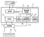
図2は、ヘッドアップディスプレイシステムの機能的な構成を表すブロック図である。図2に示すように、光源ユニット4は、車両Ve内に存在するナビゲーション装置1と通信可能であって、投射部40と、通信部41と、制御部43とを有する。[Function configuration]
FIG. 2 is a block diagram showing a functional configuration of the head-up display system. As shown in FIG. 2, the
ナビゲーション装置1は、ディスプレイや音声出力装置などの出力部、GPS受信機やジャイロセンサなどの自立測位装置、及び地図データなどを有し、車両Veの経路案内を実行する。ナビゲーション装置1は、光源ユニット4に対し、虚像Ivを表示するのに必要な情報を送信する。ナビゲーション装置1は、例えば、据置型の車載用ナビゲーション装置やスマートフォンなどの携帯端末である。 The
投射部40は、例えば画像が結像されるスクリーンを備えた投射装置であり、制御部43の制御に基づき、表示光を、フロントウィンドウ25に向けて射出する。通信部41は、ナビゲーション装置1や車両の制御部(ECU)などと通信を行い、虚像Ivの表示に必要な情報等を受信する。例えば、通信部41は、制御部43の制御に基づき、現在位置情報や車両の走行速度の情報、経路案内のルート情報などをナビゲーション装置1から受信する。 The
制御部43は、CPU(Central Processing Unit)、ROM(Read Only Memory)及びRAM(Random Access Memory)などを含んでおり、光源ユニット4全体の制御を行う。本実施例に係る制御部43は、車両情報取得部44と、表示制御部45と、位相差板回転制御部46とを有する。制御部43は、本発明における「取得手段」、「制御手段」及びプログラムを実行するコンピュータの一例である。 The
車両情報取得部44は、車両Veに関する情報(「車両情報Iw」とも呼ぶ。)を取得する。車両情報Iwは、フロントウィンドウ25の地面に対する取付角度(単に「取付角度」とも呼ぶ。)の情報、及び、フロントウィンドウ25を上端から観察した際のフロントウィンドウ25の各位置での湾曲状態(単に「湾曲状態」とも呼ぶ。)を示す情報を含む。例えば、車両情報取得部44は、車両情報Iwを、通信部41を介して車両の制御部から取得する。他の例では、車両情報取得部44は、車種(型式)ごとの車両情報Iwのデータベースを参照し、ユーザ入力により車両Veの車種等が指定された場合に、上述のデータベースから、車両Veに対応する車両情報Iwを抽出する。なお、上述のデータベースは、光源ユニット4が記憶してもよく、通信部41と通信可能なナビゲーション装置1又はサーバ装置等が記憶してもよい。 The vehicle
表示制御部45は、虚像Ivとして表示すべき画像を生成すると共に、フロントウィンドウ25上での虚像Ivの表示位置を決定し、生成した画像を示す虚像Ivが、決定した表示位置に表示されるように、投射部40に表示光を射出させる。このとき、表示制御部45は、運転者の顔を撮影する図示しないカメラの撮影画像に基づき、運転者のアイポイントを検出し、アイポイントに応じて虚像Ivの表示位置を変更してもよい。そして、表示制御部45は、虚像Ivのフロントウィンドウ25上での表示位置に関する情報(「表示位置情報Idp」とも呼ぶ。)を位相差板回転制御部46へ送信する。 The
位相差板回転制御部46は、位相差板5に対し、制御信号「Sc」を送信することで、位相差板5の回転角度を制御する。この場合、位相差板回転制御部46は、車両情報取得部44により取得された車両情報Iwと、表示制御部45から供給される表示位置情報Idpとに基づき、光源ユニット4から射出された表示光のフロントウィンドウ25の反射面での反射率を向上する方向に位相差板5を回転させる。具体的には、位相差板回転制御部46は、フロントウィンドウ25の取付角度と、虚像Ivの表示位置(即ち表示光の反射位置)でのフロントウィンドウ25の湾曲状態とに基づき、反射率が最大となるように、位相差板5の回転角度を調整する。この場合、例えば、位相差板回転制御部46は、想定され得るフロントウィンドウ25の取付角度及び湾曲状態の組み合わせごとに、設定すべき位相差板5の回転角度を示すマップを予め記憶しておき、当該マップを参照することで、位相差板5の回転角度を決定する。上述のマップは、例えば、実験又は理論計算に基づき予め生成され、光源ユニット4のメモリに記憶される。 The phase difference plate
[効果]
ここで、フロントウィンドウ25の取付角度及び湾曲状態に基づき位相差板5の回転角度を調整する処理の効果について、図3及び図4を参照して補足説明する。[effect]
Here, the effect of the process of adjusting the rotation angle of the
図3は、異なる車種の車両にヘッドアップディスプレイシステムが搭載された場合の車室内の側面図を示す。図3の例では、比較的小型の車両「Ve1」に対するフロントウィンドウ25及び表示光の光路等を実線により示し、比較的大型の車両「Ve2」に対するフロントウィンドウ25及び表示光の光路等を破線により示す。 FIG. 3 is a side view showing the interior of the vehicle when the head-up display system is installed in vehicles of different vehicle types. In the example of FIG. 3, the
図3に示すように、フロントウィンドウ25の取付角度は、車種によって異なる。具体的には、車両Ve1のフロントウィンドウ25の取付角度は、車両Ve2のフロントウィンドウ25の取付角度よりも大きい。そして、同一角度の偏光面を有する表示光がフロントウィンドウ25に入射する場合であっても、フロントウィンドウ25の取付角度によって、フロントウィンドウ25への入射角度が異なることに起因して、フロントウィンドウ25での反射率が異なる。よって、車種によっては、フロントウィンドウ25での表示光の反射率が、運転者の虚像Ivの視認性が最適となる反射率とならない場合がある。 As shown in FIG. 3, the mounting angle of the
以上を勘案し、位相差板回転制御部46は、車両情報Iwが示すフロントウィンドウ25の取付角度に基づき、位相差板5の回転角度を調整して表示光の偏光面の角度を変更する。これにより、位相差板回転制御部46は、車種によらずに、鮮明な虚像Ivを運転者に視認させることができる。 In consideration of the above, the phase difference plate
図4は、フロントウィンドウ25を上方から観察した図を示す。図4に示す範囲「DR1」、「DR2」は、虚像Ivの表示位置が異なる場合に、各虚像Ivに対応する表示光が入射するフロントウィンドウ25の範囲を示す。図4に示すように、表示光が入射する位置でのフロントウィンドウ25の湾曲状態は、虚像Ivの表示位置に応じて異なる。また、フロントウィンドウ25の形状は、車種によって異なるため、表示光が入射する位置でのフロントウィンドウ25の湾曲状態は、車種によっても異なる。従って、車種及び虚像Ivの表示位置によっては、フロントウィンドウ25での表示光の反射率が、運転者の虚像Ivの視認性が最適となる反射率とならない場合がある。 FIG. 4 shows a view of the
以上を勘案し、位相差板回転制御部46は、車両情報Iw及び表示位置情報Idpに基づき、虚像Ivの表示位置でのフロントウィンドウ25の湾曲状態を認識する。そして、位相差板回転制御部46は、当該湾曲状態に基づき、位相差板5の回転角度を調整して表示光の偏光面の角度を変更する。これにより、位相差板回転制御部46は、車種及び虚像Ivの表示位置によらずに、鮮明な虚像Ivを運転者に表示させることができる。 In consideration of the above, the phase difference plate
以上説明したように、第1実施例に係るヘッドアップディスプレイシステムは、車両Veに設置され、光源ユニット4から射出された表示光をフロントウィンドウ25の反射面で反射させることにより、虚像Ivを車両Veの室内から視認可能に表示する。ヘッドアップディスプレイシステムは、位相差板5と、光源ユニット4とを備える。位相差板5は、光源ユニット4とフロントウィンドウ25の反射面との間の光路上に配置され、光源ユニット4から射出された光の偏光面を回転させる。光源ユニット4は、車両情報Iwを取得する車両情報取得部44と、位相差板5の回転角度を制御する位相差板回転制御部46とを有する。ここで、位相差板回転制御部46は、車両情報取得部44により取得された車両情報Iwに基づいて、フロントウィンドウ25での表示光の反射率が向上する方向に位相差板5を回転させる。これにより、ヘッドアップディスプレイシステムは、フロントウィンドウ25での表示光の反射率を高くし、虚像Ivの視認性を好適に向上させることができる。 As described above, the head-up display system according to the first embodiment is installed in the vehicle Ve, and the display light emitted from the
<第2実施例>
第2実施例では、光源ユニット4の制御部43は、第1実施例の処理に加え、観察者である運転者のサングラスの着用の有無を判定し、サングラスを着用していると判断した場合には、サングラスでの表示光の透過率が最大となるように位相差板5の回転角度を定める。<Second embodiment>
In the second embodiment, in addition to the processing of the first embodiment, the
図5(A)は、第2実施例に係るヘッドアップディスプレイシステムの概略構成を示し、図5(B)は、第2実施例に係るヘッドアップディスプレイシステムの機能的なブロック図を示す。図5(A)、(B)に示すように、ヘッドアップディスプレイシステムには、運転者の顔を撮影する車室内撮影カメラ6が設けられる。また、図5(B)に示すように、制御部43は、サングラス着用判断部47を備える。なお、第1実施例と同様の構成については、適宜同一の符号を付し、その説明を省略する。 FIG. 5A shows a schematic configuration of the head-up display system according to the second embodiment, and FIG. 5B shows a functional block diagram of the head-up display system according to the second embodiment. As shown in FIGS. 5A and 5B, the head-up display system is provided with a vehicle interior photographing camera 6 that photographs the driver's face. Further, as shown in FIG. 5B, the
サングラス着用判断部47は、車室内撮影カメラ6が生成した画像を取得し、当該画像に対して公知の画像認識処理を行うことで、運転者のサングラスの着用の有無を判定する。そして、サングラス着用判断部47は、運転者のサングラスの着用の有無に関する情報(「サングラス着用情報Isg」とも呼ぶ。)を位相差板回転制御部46へ供給する。サングラス着用判断部47は、本発明における「判断手段」の一例である。 The sunglasses wearing
位相差板回転制御部46は、サングラス着用情報Isgに基づき、運転者がサングラスを着用していると判断した場合、当該サングラスが偏光サングラスであると見なし、偏光サングラスでの表示光の透過率が向上する方向に位相差板5を回転させる。具体的には、位相差板回転制御部46は、この場合、フロントウィンドウ25を反射した表示光が偏光サングラスに入射する際の透過率が最大となる位相差板5の回転角度を認識し、当該回転角度になるように位相差板5を回転させる。上述の透過率が最大となる回転角度は、例えば、実験又は理論的に導出され、光源ユニット4のメモリに予め記憶される。これにより、位相差板回転制御部46は、運転者が偏光サングラスを着用している場合であっても、好適に虚像Ivを視認させることができる。 When the driver judges that the driver wears sunglasses based on the sunglasses wearing information Isg, the retardation plate
一方、位相差板回転制御部46は、運転者がサングラスを着用していないと判断した場合、第1実施例と同様に位相差板5の回転角度を定める。即ち、位相差板回転制御部46は、この場合、車両情報Iw及び表示位置情報Idpに基づき、フロントウィンドウ25の取付角度及び虚像Ivの表示位置での湾曲状態を認識し、フロントウィンドウ25での表示光の反射率が最大となるように、位相差板5の回転角度を定める。 On the other hand, the phase difference plate
次に、第2実施例の効果について補足説明する。一般に、市場に広く普及している偏光サングラスは、眩しさや反射光を効果的にカットできるレンズを使用している。このレンズは、自然光を通しつつ紫外線や反射光をカットすることができ、視界を良好に保つ機能を有している。一方、ヘッドアップディスプレイシステムは、フロントウィンドウ25の反射光を運転者の目に入射させることで虚像Ivを視認させるため、運転者が偏光サングラスを着用している場合、虚像Ivの視認性が極めて低くなるという課題がある。 Next, the effect of the second embodiment will be supplementarily described. In general, polarized sunglasses that are widely used in the market use lenses that can effectively cut glare and reflected light. This lens has a function of blocking ultraviolet rays and reflected light while allowing natural light to pass therethrough, thereby maintaining a good visual field. On the other hand, in the head-up display system, the reflected light of the
以上を勘案し、第2実施例では、位相差板回転制御部46は、運転者がサングラスを着用しているとサングラス着用判断部47が判断した場合、フロントウィンドウ25を反射した表示光の偏光サングラスでの透過率が向上する方向に、位相差板5を回転させる。これにより、虚像Ivの観察者である運転者に、より鮮明な虚像Ivを視認させることができる。 In consideration of the above, in the second embodiment, the phase difference plate
<第3実施例>
第3実施例では、光源ユニット4の制御部43は、第1実施例の処理に加え、車外での明るさを検知し、当該明るさが暗いほど、フロントウィンドウ25での表示光の反射率が下がるように位相差板5の回転角度を定める。これにより、車外の明るさに適した輝度の虚像Ivを運転者に好適に視認させる。<Third embodiment>
In the third embodiment, in addition to the processing of the first embodiment, the
図6は、第3実施例に係るヘッドアップディスプレイシステムの機能的なブロック図を示す。図6に示すように、制御部43は、明るさ検知部48を備える。なお、第1実施例と同様の構成については、適宜同一の符号を付し、その説明を省略する。 FIG. 6 shows a functional block diagram of the head-up display system according to the third embodiment. As shown in FIG. 6, the
明るさ検知部48は、車外に取り付けられた図示しないセンサから取得した検出信号に基づき、又は、車両の制御部から取得したヘッドライトの点灯スイッチの状態を示す信号に基づき、車外の明るさを検出又は推定する。そして、明るさ検知部48は、検出又は推定した車外の明るさに適したフロントウィンドウ25での表示光の反射率になるように、位相差板5の回転角度を調整する。明るさ検知部48は、本発明における「検知手段」の一例である。 The
例えば、位相差板回転制御部46は、検出又は推定した車外の明るさの度合いが所定値より高い場合には、第1実施例と同様に、フロントウィンドウ25での表示光の反射率が最大となるように位相差板5の回転角度を定める。これにより、位相差板回転制御部46は、虚像Ivの見た目上の輝度を高くし、日中等の外が明るい時間帯であっても虚像Ivを好適に視認させる。
一方、位相差板回転制御部46は、検出又は推定した車外の明るさの度合いが所定値以下の場合に、車外が暗いほど、フロントウィンドウ25での表示光の反射率を下げて虚像Ivの輝度を低くするように、位相差板5の回転角度を調整する。この場合、位相差板回転制御部46は、例えば、車外の各明るさの度合いに適したフロントウィンドウ25での反射率のマップ等を予め記憶しておき、当該マップ等を参照し、検出又は推定した車外の明るさに好適なフロントウィンドウ25での表示光の反射率を認識する。そして、位相差板回転制御部46は、目標となるフロントウィンドウ25での表示光の反射率を達成するために必要な位相差板5の回転角度を認識し、当該回転角度になるように位相差板5を回転させる。この場合、好適には、位相差板回転制御部46は、車両情報Iw及び表示位置情報Idpから認識したフロントウィンドウ25の取付角度及び湾曲状態を勘案し、目標となるフロントウィンドウ25での表示光の反射率を達成するために必要な位相差板5の回転角度を認識する。For example, when the detected or estimated degree of brightness outside the vehicle is higher than a predetermined value, the phase difference plate
On the other hand, the phase difference plate
以上のように、第3実施例に係るヘッドアップディスプレイシステムは、車外の明るさを検知し、虚像Ivが当該明るさに適した輝度になるように、位相差板5の回転角度を定める。これにより、車外の明るさに適した輝度の虚像Ivを運転者に好適に視認させることができる。 As described above, the head-up display system according to the third embodiment detects the brightness outside the vehicle and determines the rotation angle of the
<変形例>
以下、上述の第1〜第3実施例に好適な変形例について説明する。以下の変形例は、任意に組み合わせて第1〜第3実施例に適用してもよい。<Modification>
Hereinafter, modified examples suitable for the above-described first to third embodiments will be described. The following modifications may be arbitrarily combined and applied to the first to third embodiments.
(変形例1)
位相差板回転制御部46は、位相差板5を回転させる代わりに、投射部40を回転させることで、表示光の偏光面の向きを調整してもよい。(Modification 1)
The phase difference plate
この場合、投射部40は、位相差板回転制御部46から送信される制御信号に基づき、光の射出方向を軸として回転自在に構成される。そして、位相差板回転制御部46は、第1〜第3実施例に基づき、表示光の偏光面の向きが最適な向きとなるように、投射部40の回転角度を定める。また、この場合、表示制御部45は、虚像Ivとして視認させる画像の向きが変わらないように、投射部40の回転角度に応じて、投射部40に射出させる画像の向きを変える。この態様によっても、ヘッドアップディスプレイシステムは、実施例と同様に、虚像Ivの視認性を好適に向上させることができる。 In this case, the
(変形例2)
光源ユニット4は、位相差板5を内部に有してもよい。この場合であっても、位相差板5は、投射部40から射出された光が照射される位置に配置される。(Modification 2)
The
(変形例3)
ナビゲーション装置1は、光源ユニット4の代わりに、位相差板5の回転角度の制御等の処理を実行してもよい。(Modification 3)
The
図7は、本変形例に係るヘッドアップディスプレイシステムの構成例を示す。図7の例では、ナビゲーション装置1は、位相差板5に対して制御信号Scを送信することで、位相差板5の回転角度を調整する。この場合、ナビゲーション装置1は、各実施例で説明した車両情報取得部44、表示制御部45、及び位相差板回転制御部46等の制御部43の処理を実行するCPU等を有し、第1〜第3実施例に基づき、フロントウィンドウ25での表示光の反射率が最適になるように位相差板5の回転角度を調整する。また、図7の例では、ナビゲーション装置1は、通信部41を介し、虚像Ivとして表示する画像や表示位置などを指定する制御信号を投射部40へ供給することで、投射部40に表示光を射出させる。 FIG. 7 shows a configuration example of a head-up display system according to this modification. In the example of FIG. 7, the
なお、本変形例では、ナビゲーション装置1のCPUは、本発明における「取得手段」、「制御手段」及びプログラムを実行するコンピュータの一例である。 In this modification, the CPU of the
(変形例4)
各実施例では、光源ユニット4は、現在位置情報や地図データなどの投射部40に表示光を射出させるのに必要な情報をナビゲーション装置1から受信した。これに代えて、光源ユニット4は、GPS受信機やジャイロセンサなどの自立測位装置、及び地図データなどを有し、ナビゲーション装置1と通信を行うことなく、虚像Ivとして表示させる画像等を生成し、表示光を射出してもよい。(Modification 4)
In each of the embodiments, the
(変形例5)
投射部40は、液晶ディスプレイであってもよい。この場合、液晶ディスプレイが光源ユニット4の機能を全て有してもよく、変形例3と同様にナビゲーション装置1が制御部43の機能を有してもよい。(Modification 5)
The
1 ナビゲーション装置
4 光源ユニット
5 位相差板
6 車室内撮影カメラ
8 凹面鏡
25 フロントウィンドウ
28 ボンネット
29 ダッシュボード1
Claims (5)
Translated fromJapanese前記光を射出する光源と前期反射面との間の光路上に配置され、前記光の偏光面を回転させる位相変更手段と、
前記位相変更手段の回転角度を制御する制御手段と、
を備え、
前記制御手段は、前記画像の表示位置に関する情報に基づき、前記画像を構成する光が前記反射面で反射する位置での前記フロントウィンドウの湾曲状態を認識し、当該湾曲状態に基づいて、前記画像を構成する光の前記反射面での反射率が向上する方向に前記偏光面を回転させるべく前記位相変更手段を制御することを特徴とするヘッドアップディスプレイ。A head-up display that projects light forming an image on a reflective surface of a front window of a vehicle,
Phase changing means arranged on the optical path between the light source for emitting the light and the early reflection surface, for rotating the polarization plane of the light,
Control means for controlling the rotation angle of the phase changing means,
Equipped with
The control meansrecognizes a curved state of the front window at a position where light forming the image is reflected by the reflecting surface, based on information about a display position of the image, and based on the curved state, the image A head-up display, characterizedin that thephase changing means is controlled so as to rotate thepolarization plane in a direction in which the reflectance of the light constituting the above is improved on the reflectionsurface .
前記光を射出する光源と前期反射面との間の光路上に配置され、前記光の偏光面を回転させる位相変更工程と、 A phase changing step of rotating the polarization plane of the light, which is disposed on the optical path between the light source that emits the light and the early reflection surface,
前記位相変更工程の回転角度を制御する制御工程と、 A control step of controlling the rotation angle of the phase changing step,
を有し、Have
前記制御工程は、前記画像の表示位置に関する情報に基づき、前記画像を構成する光が前記反射面で反射する位置での前記フロントウィンドウの湾曲状態を認識し、当該湾曲状態に基づいて、前記画像を構成する光の前記反射面での反射率が向上する方向に前記偏光面を回転するように制御することを特徴とする制御方法。 The control step recognizes a curved state of the front window at a position where light forming the image is reflected by the reflection surface, based on information about a display position of the image, and based on the curved state, the image The control method is characterized in that the polarization plane is controlled so as to rotate in a direction in which the reflectance of the light constituting the above is improved on the reflection surface.
前記光を射出する光源と前期反射面との間の光路上に配置され、前記光の偏光面を回転させる位相変更手段と、 Phase changing means arranged on the optical path between the light source for emitting the light and the early reflection surface, for rotating the polarization plane of the light,
前記位相変更手段の回転角度を制御する制御手段、 Control means for controlling the rotation angle of the phase changing means,
として前記コンピュータを機能させ、Functioning the computer as
前記制御手段は、前記画像の表示位置に関する情報に基づき、前記画像を構成する光が前記反射面で反射する位置での前記フロントウィンドウの湾曲状態を認識し、当該湾曲状態に基づいて、前記画像を構成する光の前記反射面での反射率が向上する方向に前記偏光面を回転させるべく前記位相変更手段を制御することを特徴とするプログラム。 The control means recognizes a curved state of the front window at a position where light forming the image is reflected by the reflecting surface, based on information about a display position of the image, and based on the curved state, the image A program for controlling the phase changing means so as to rotate the polarization plane in a direction in which the reflectance of the light constituting the above is improved on the reflection surface.
Priority Applications (1)
| Application Number | Priority Date | Filing Date | Title |
|---|---|---|---|
| JP2019115444AJP6693594B2 (en) | 2019-06-21 | 2019-06-21 | Head-up display, control method, program, and storage medium |
Applications Claiming Priority (1)
| Application Number | Priority Date | Filing Date | Title |
|---|---|---|---|
| JP2019115444AJP6693594B2 (en) | 2019-06-21 | 2019-06-21 | Head-up display, control method, program, and storage medium |
Related Parent Applications (1)
| Application Number | Title | Priority Date | Filing Date |
|---|---|---|---|
| JP2015004353ADivisionJP2016130066A (en) | 2015-01-13 | 2015-01-13 | Head-up display, control method, program, and storage medium |
Publications (2)
| Publication Number | Publication Date |
|---|---|
| JP2019196172A JP2019196172A (en) | 2019-11-14 |
| JP6693594B2true JP6693594B2 (en) | 2020-05-13 |
Family
ID=68538234
Family Applications (1)
| Application Number | Title | Priority Date | Filing Date |
|---|---|---|---|
| JP2019115444AExpired - Fee RelatedJP6693594B2 (en) | 2019-06-21 | 2019-06-21 | Head-up display, control method, program, and storage medium |
Country Status (1)
| Country | Link |
|---|---|
| JP (1) | JP6693594B2 (en) |
Families Citing this family (2)
| Publication number | Priority date | Publication date | Assignee | Title |
|---|---|---|---|---|
| JP7495447B2 (en)* | 2022-07-07 | 2024-06-04 | 矢崎総業株式会社 | Vehicle display device |
| TW202443242A (en)* | 2022-12-28 | 2024-11-01 | 日商索尼集團公司 | Display device and display system |
Family Cites Families (6)
| Publication number | Priority date | Publication date | Assignee | Title |
|---|---|---|---|---|
| US5303085A (en)* | 1992-02-07 | 1994-04-12 | Rallison Richard D | Optically corrected helmet mounted display |
| JP3573765B2 (en)* | 1993-03-18 | 2004-10-06 | カルソニックカンセイ株式会社 | Vehicle head-up display device |
| JP3313182B2 (en)* | 1993-04-21 | 2002-08-12 | 矢崎総業株式会社 | Display device for vehicles |
| DE102007007162A1 (en)* | 2007-02-09 | 2008-08-14 | GM Global Technology Operations, Inc., Detroit | Holographic information display |
| JP2012103331A (en)* | 2010-11-08 | 2012-05-31 | Denso Corp | Head-up display device for vehicle |
| JP6027727B2 (en)* | 2011-09-09 | 2016-11-16 | 矢崎総業株式会社 | Vehicle display device |
- 2019
- 2019-06-21JPJP2019115444Apatent/JP6693594B2/ennot_activeExpired - Fee Related
Also Published As
| Publication number | Publication date |
|---|---|
| JP2019196172A (en) | 2019-11-14 |
Similar Documents
| Publication | Publication Date | Title |
|---|---|---|
| JP6717856B2 (en) | Head up display device | |
| JP2016130066A (en) | Head-up display, control method, program, and storage medium | |
| JP6437532B2 (en) | Data display glasses with anti-glare screen | |
| US9823471B2 (en) | Display device | |
| US7199767B2 (en) | Enhanced vision for driving | |
| US8693103B2 (en) | Display device and display method | |
| US10971116B2 (en) | Display device, control method for placement of a virtual image on a projection surface of a vehicle, and storage medium | |
| JP2019166891A (en) | Information display device | |
| JP6674793B2 (en) | Driving support information display device | |
| CN109791300A (en) | Head-up display system | |
| CN114326119A (en) | Head-up display device and head-up display method | |
| US12361728B2 (en) | Vehicle display device | |
| JP6693594B2 (en) | Head-up display, control method, program, and storage medium | |
| JP7053857B2 (en) | Head-up display device | |
| KR20170008430A (en) | Head up display | |
| CN108931851A (en) | Head-up-display system and automobile | |
| US20250010720A1 (en) | Method, computer program and apparatus for controlling an augmented reality display device | |
| JP2022044136A (en) | Display control device, head-up display device, and display control method for head-up display device | |
| JP7182368B2 (en) | VEHICLE DISPLAY DEVICE, METHOD AND COMPUTER PROGRAM FOR CONTROLLING VEHICLE DISPLAY DEVICE | |
| EP4414770A1 (en) | Image projecting device and image projecting method | |
| JP7344635B2 (en) | heads up display device | |
| US20240176140A1 (en) | Display system, display control method, and storage medium | |
| US20240255756A1 (en) | Control apparatus, control method, storage medium, and movable apparatus | |
| JP2024007661A (en) | heads up display device | |
| CN120245718A (en) | Vehicle system for detecting polarized sunglasses |
Legal Events
| Date | Code | Title | Description |
|---|---|---|---|
| A621 | Written request for application examination | Free format text:JAPANESE INTERMEDIATE CODE: A621 Effective date:20190621 | |
| A711 | Notification of change in applicant | Free format text:JAPANESE INTERMEDIATE CODE: A711 Effective date:20190723 | |
| A521 | Request for written amendment filed | Free format text:JAPANESE INTERMEDIATE CODE: A821 Effective date:20190723 | |
| A521 | Request for written amendment filed | Free format text:JAPANESE INTERMEDIATE CODE: A523 Effective date:20190823 | |
| A521 | Request for written amendment filed | Free format text:JAPANESE INTERMEDIATE CODE: A523 Effective date:20190911 | |
| TRDD | Decision of grant or rejection written | ||
| A01 | Written decision to grant a patent or to grant a registration (utility model) | Free format text:JAPANESE INTERMEDIATE CODE: A01 Effective date:20200317 | |
| A977 | Report on retrieval | Free format text:JAPANESE INTERMEDIATE CODE: A971007 Effective date:20200319 | |
| A61 | First payment of annual fees (during grant procedure) | Free format text:JAPANESE INTERMEDIATE CODE: A61 Effective date:20200330 | |
| R150 | Certificate of patent or registration of utility model | Ref document number:6693594 Country of ref document:JP Free format text:JAPANESE INTERMEDIATE CODE: R150 | |
| LAPS | Cancellation because of no payment of annual fees |