JP6693060B2 - Display system, display device, display device control method, and program - Google Patents
Display system, display device, display device control method, and programDownload PDFInfo
- Publication number
- JP6693060B2 JP6693060B2JP2015135194AJP2015135194AJP6693060B2JP 6693060 B2JP6693060 B2JP 6693060B2JP 2015135194 AJP2015135194 AJP 2015135194AJP 2015135194 AJP2015135194 AJP 2015135194AJP 6693060 B2JP6693060 B2JP 6693060B2
- Authority
- JP
- Japan
- Prior art keywords
- unit
- data
- image
- display
- user
- Prior art date
- Legal status (The legal status is an assumption and is not a legal conclusion. Google has not performed a legal analysis and makes no representation as to the accuracy of the status listed.)
- Expired - Fee Related
Links
Images


Classifications
- G—PHYSICS
- G06—COMPUTING OR CALCULATING; COUNTING
- G06F—ELECTRIC DIGITAL DATA PROCESSING
- G06F3/00—Input arrangements for transferring data to be processed into a form capable of being handled by the computer; Output arrangements for transferring data from processing unit to output unit, e.g. interface arrangements
- G06F3/14—Digital output to display device ; Cooperation and interconnection of the display device with other functional units
- G06F3/1454—Digital output to display device ; Cooperation and interconnection of the display device with other functional units involving copying of the display data of a local workstation or window to a remote workstation or window so that an actual copy of the data is displayed simultaneously on two or more displays, e.g. teledisplay
- G—PHYSICS
- G02—OPTICS
- G02B—OPTICAL ELEMENTS, SYSTEMS OR APPARATUS
- G02B27/00—Optical systems or apparatus not provided for by any of the groups G02B1/00 - G02B26/00, G02B30/00
- G02B27/0093—Optical systems or apparatus not provided for by any of the groups G02B1/00 - G02B26/00, G02B30/00 with means for monitoring data relating to the user, e.g. head-tracking, eye-tracking
- G—PHYSICS
- G02—OPTICS
- G02B—OPTICAL ELEMENTS, SYSTEMS OR APPARATUS
- G02B27/00—Optical systems or apparatus not provided for by any of the groups G02B1/00 - G02B26/00, G02B30/00
- G02B27/01—Head-up displays
- G02B27/017—Head mounted
- G02B27/0172—Head mounted characterised by optical features
- G—PHYSICS
- G06—COMPUTING OR CALCULATING; COUNTING
- G06F—ELECTRIC DIGITAL DATA PROCESSING
- G06F3/00—Input arrangements for transferring data to be processed into a form capable of being handled by the computer; Output arrangements for transferring data from processing unit to output unit, e.g. interface arrangements
- G06F3/002—Specific input/output arrangements not covered by G06F3/01 - G06F3/16
- G06F3/005—Input arrangements through a video camera
- G—PHYSICS
- G06—COMPUTING OR CALCULATING; COUNTING
- G06F—ELECTRIC DIGITAL DATA PROCESSING
- G06F3/00—Input arrangements for transferring data to be processed into a form capable of being handled by the computer; Output arrangements for transferring data from processing unit to output unit, e.g. interface arrangements
- G06F3/01—Input arrangements or combined input and output arrangements for interaction between user and computer
- G06F3/011—Arrangements for interaction with the human body, e.g. for user immersion in virtual reality
- G06F3/012—Head tracking input arrangements
- G—PHYSICS
- G02—OPTICS
- G02B—OPTICAL ELEMENTS, SYSTEMS OR APPARATUS
- G02B27/00—Optical systems or apparatus not provided for by any of the groups G02B1/00 - G02B26/00, G02B30/00
- G02B27/01—Head-up displays
- G02B27/0101—Head-up displays characterised by optical features
- G02B2027/0138—Head-up displays characterised by optical features comprising image capture systems, e.g. camera
- G—PHYSICS
- G02—OPTICS
- G02B—OPTICAL ELEMENTS, SYSTEMS OR APPARATUS
- G02B27/00—Optical systems or apparatus not provided for by any of the groups G02B1/00 - G02B26/00, G02B30/00
- G02B27/01—Head-up displays
- G02B27/0101—Head-up displays characterised by optical features
- G02B2027/014—Head-up displays characterised by optical features comprising information/image processing systems
- G—PHYSICS
- G02—OPTICS
- G02B—OPTICAL ELEMENTS, SYSTEMS OR APPARATUS
- G02B27/00—Optical systems or apparatus not provided for by any of the groups G02B1/00 - G02B26/00, G02B30/00
- G02B27/01—Head-up displays
- G02B27/0101—Head-up displays characterised by optical features
- G02B2027/0141—Head-up displays characterised by optical features characterised by the informative content of the display
- G—PHYSICS
- G06—COMPUTING OR CALCULATING; COUNTING
- G06F—ELECTRIC DIGITAL DATA PROCESSING
- G06F3/00—Input arrangements for transferring data to be processed into a form capable of being handled by the computer; Output arrangements for transferring data from processing unit to output unit, e.g. interface arrangements
- G06F3/14—Digital output to display device ; Cooperation and interconnection of the display device with other functional units
- G06F3/1423—Digital output to display device ; Cooperation and interconnection of the display device with other functional units controlling a plurality of local displays, e.g. CRT and flat panel display
- G—PHYSICS
- G06—COMPUTING OR CALCULATING; COUNTING
- G06Q—INFORMATION AND COMMUNICATION TECHNOLOGY [ICT] SPECIALLY ADAPTED FOR ADMINISTRATIVE, COMMERCIAL, FINANCIAL, MANAGERIAL OR SUPERVISORY PURPOSES; SYSTEMS OR METHODS SPECIALLY ADAPTED FOR ADMINISTRATIVE, COMMERCIAL, FINANCIAL, MANAGERIAL OR SUPERVISORY PURPOSES, NOT OTHERWISE PROVIDED FOR
- G06Q10/00—Administration; Management
- G06Q10/06—Resources, workflows, human or project management; Enterprise or organisation planning; Enterprise or organisation modelling
- G—PHYSICS
- G09—EDUCATION; CRYPTOGRAPHY; DISPLAY; ADVERTISING; SEALS
- G09B—EDUCATIONAL OR DEMONSTRATION APPLIANCES; APPLIANCES FOR TEACHING, OR COMMUNICATING WITH, THE BLIND, DEAF OR MUTE; MODELS; PLANETARIA; GLOBES; MAPS; DIAGRAMS
- G09B5/00—Electrically-operated educational appliances
- G09B5/06—Electrically-operated educational appliances with both visual and audible presentation of the material to be studied
Landscapes
- Engineering & Computer Science (AREA)
- Physics & Mathematics (AREA)
- Theoretical Computer Science (AREA)
- General Physics & Mathematics (AREA)
- General Engineering & Computer Science (AREA)
- Human Computer Interaction (AREA)
- Optics & Photonics (AREA)
- Multimedia (AREA)
- User Interface Of Digital Computer (AREA)
- Controls And Circuits For Display Device (AREA)
- Closed-Circuit Television Systems (AREA)
- Testing, Inspecting, Measuring Of Stereoscopic Televisions And Televisions (AREA)
- Health & Medical Sciences (AREA)
- Audiology, Speech & Language Pathology (AREA)
- General Health & Medical Sciences (AREA)
Description
Translated fromJapanese本発明は、表示システム、表示装置、表示装置の制御方法、及び、プログラムに関する。 The present invention relates to a display system, a display device, a display device control method, and a program.
従来、作業を行う人を支援するため、頭部に装着するヘッドマウントディスプレイ(Head Mounted Display:HMD)と呼ばれる表示装置を使用する例が知られている(例えば、特許文献1参照)。特許文献1記載のシステムでは、作業者が装着するHMDが電子カメラを備え、HMDの電子カメラが撮像した作業対象が、指示者が操作するホストPCに表示される。指示者は、電子カメラが撮像した作業対象を見て、作業者のHMDに警告表示等を行わせる。 2. Description of the Related Art Conventionally, there is known an example of using a display device called a head mounted display (HMD) mounted on the head in order to support a person who performs a work (for example, refer to Patent Document 1). In the system described in
上記従来の構成では、作業を支援する側である指示者はPCに表示される画像から作業者の状態を把握するが、作業者から作業を支援する側に対し、よりわかりやすい態様で多くの情報を伝達することが望まれていた。
本発明は上記事情に鑑みてなされたものであり、頭部装着型の表示装置を使用して動作を行う人に対し、他の人が支援を行う場合に、動作に関する多くの情報をよりわかりやすく伝達できるようにすることを目的とする。In the above-described conventional configuration, the instructor, who is the side supporting the work, grasps the state of the worker from the image displayed on the PC, but the operator supporting the work receives a lot of information in a more understandable manner. Was desired to be transmitted.
The present invention has been made in view of the above circumstances, and when a person performing an operation using a head-mounted display device is assisted by another person, much information regarding the operation can be more easily understood. The purpose is to facilitate communication.
上記目的を達成するために、本発明は、複数の頭部装着型の表示装置を備えるシステムであって、前記表示装置は、使用者に画像を視認させるとともに外景を透過する表示部と、他の前記表示装置と通信する通信部と、前記使用者の視界と重なる範囲を撮像する撮像部と、前記使用者の状態に関する判定を行う判定部と、制御部と、を備え、前記制御部は、前記撮像部の撮像画像に基づき視界データを他の前記表示装置に送信し、前記判定部の判定結果に基づき、前記通信部により他の前記表示装置に通知データを送信し、他の前記表示装置から送信されるデータに基づき前記表示部に表示を実行させること、を特徴とする。
本発明によれば、複数の表示装置の間で視界に関するデータと入力に関するデータとを共有できるので、複数の使用者が表示装置を装着することにより、視界と操作とを共有できる。これにより、例えば、動作を行う人と動作を支援する人が互いに頭部装着型の表示装置を装着することで、動作に関する多くの情報をよりわかりやすく伝達できる。また、使用者の状態に関する判定を行うことにより、適切なタイミングで通知データを送信できる。従って、使用者が、他の使用者に対し作業等を支援し、或いは、作業等の実行状態の管理を容易に、的確に行うことができる。In order to achieve the above-mentioned object, the present invention is a system including a plurality of head-mounted display devices, wherein the display device allows a user to visually recognize an image and a display unit that transmits an outside scene, The communication unit that communicates with the display device, an image capturing unit that captures a range that overlaps the field of view of the user, a determination unit that determines the state of the user, and a control unit, the control unit, , Transmitting the view field data to the other display device based on the image captured by the image capturing unit, and transmitting the notification data to the other display device via the communication unit based on the determination result of the determining unit, and displaying the other display. The display unit is caused to execute a display based on data transmitted from the device.
According to the present invention, since the data related to the field of view and the data related to the input can be shared among the plurality of display devices, the field of view and the operation can be shared by a plurality of users wearing the display devices. Accordingly, for example, a person performing an action and a person supporting the action wear the head-mounted display device to each other, so that much information regarding the action can be transmitted in a more understandable manner. Further, the notification data can be transmitted at an appropriate timing by making a determination regarding the state of the user. Therefore, the user can assist other users with work or manage the execution state of work and the like easily and accurately.
また、本発明は、上記表示システムにおいて、前記判定部は、前記使用者の動作に基づき、前記使用者の状態が予め設定された通知を行うべき状態に該当するかを判定し、前記判定部が、前記使用者の状態が通知を行うべき状態に該当すると判定した場合に、前記制御部が前記通信部により他の前記表示装置に通知データを送信させること、を特徴とする。
本発明によれば、使用者が通知を行うべき状態であることを判定して、他の装置に対して通知データを送信できる。Further, in the display system according to the present invention, the determination unit determines whether the state of the user corresponds to a preset notification state based on the operation of the user, and the determination unit However, when it is determined that the state of the user corresponds to a state to be notified, the control unit causes the communication unit to transmit the notification data to another display device.
According to the present invention, it is possible to determine that the user is in a state to be notified and transmit the notification data to another device.
また、本発明は、上記表示システムにおいて、入力を認識する認識部を備え、前記判定部は、前記認識部が認識する入力に基づき前記使用者の状態を判定すること、を特徴とする。
本発明によれば、使用者または他の人による入力を認識して、使用者の状態を適切に判定できる。また、使用者または他の人は、入力を認識させることで、意図的に通知データを他の装置に送信させることができる。Further, the present invention is characterized in that, in the above display system, a recognition unit that recognizes an input is provided, and the determination unit determines the state of the user based on the input recognized by the recognition unit.
According to the present invention, the state of the user can be appropriately determined by recognizing the input by the user or another person. Further, the user or another person can intentionally cause the notification data to be transmitted to another device by recognizing the input.
また、本発明は、上記表示システムにおいて、音声を検出する音声処理部を備え、前記認識部は、前記音声処理部により検出される音声に基づき入力を認識すること、を特徴とする。
本発明によれば、音声による入力を行うことができ、複数の表示装置の間で、より容易に情報を伝達できる。Further, the present invention is characterized in that, in the above display system, a voice processing unit that detects voice is provided, and the recognition unit recognizes an input based on the voice detected by the voice processing unit.
According to the present invention, it is possible to perform input by voice, and it is possible to more easily transmit information between a plurality of display devices.
また、本発明は、上記表示システムにおいて、前記制御部は、前記音声処理部により検出される音声に基づき前記認識部が認識する入力を示すデータを他の前記表示装置に送信すること、を特徴とする。
本発明によれば、表示装置に対して音声により入力された内容を、他の表示装置を装着する使用者に知らせることができる。Further, in the display system according to the present invention, the control unit transmits data indicating an input recognized by the recognition unit based on a voice detected by the voice processing unit to another display device. And
According to the present invention, it is possible to notify the user wearing another display device of the content input by voice to the display device.
また、本発明は、上記表示システムにおいて、前記表示部の動きを検出する動き検出部を備え、前記認識部は、前記動き検出部が検出する動きに基づき入力を認識すること、を特徴とする。
本発明によれば、表示部または表示部を装着した使用者の動きによる入力を行うことができる。Further, the present invention is characterized in that, in the above display system, a motion detection unit that detects a motion of the display unit is provided, and the recognition unit recognizes an input based on the motion detected by the motion detection unit. ..
According to the present invention, it is possible to perform input by the movement of the display unit or the user wearing the display unit.
また、本発明は、上記表示システムにおいて、前記認識部は、前記撮像部の撮像画像に基づき入力を認識すること、を特徴とする。
本発明によれば、撮像画像から入力を認識できるので、より容易に入力を行うことができる。Further, in the display system according to the present invention, the recognition unit recognizes an input based on a captured image of the imaging unit.
According to the present invention, since the input can be recognized from the captured image, the input can be performed more easily.
また、本発明は、上記表示システムにおいて、前記制御部は、動作を案内する案内情報、前記動作の実行順を指定する順序情報、及び、前記動作の実行状態を示す状態情報を含む動作案内データを再生する再生処理を行い、前記再生処理において前記表示部に表示を実行し、前記認識部で認識する入力に基づいて再生中の前記動作案内データの状態情報を更新し、前記通信部によって、前記再生処理を行った前記動作案内データを他の前記表示装置に送信すること、を特徴とする。
本発明によれば、表示装置を装着して動作を実行する使用者に対して動作を案内でき、この案内に従って動作をした記録を含むデータを、他の表示装置が引き継いで使用できる。Further, in the display system according to the present invention, the control unit includes operation guide data including guide information that guides an operation, order information that specifies an execution order of the operation, and status information that indicates an execution state of the operation. Is performed, display is performed on the display unit in the reproduction process, state information of the motion guidance data being reproduced is updated based on an input recognized by the recognition unit, and the communication unit The operation guide data that has been subjected to the reproduction processing is transmitted to another display device.
According to the present invention, it is possible to guide a motion to a user who wears the display device and executes the motion, and other display devices can continue to use the data including the record of the motion in accordance with the motion.
また、本発明は、上記表示システムにおいて、前記撮像部は、前記使用者が注視する方向と重なる範囲を撮像すること、を特徴とする。
本発明によれば、使用者が注視する方向の画像を他の使用者に見せることができる。Further, the present invention is characterized in that, in the display system, the image capturing unit captures an image of a range overlapping with a direction in which the user is gazing.
According to the present invention, the image in the direction in which the user is gazing can be shown to other users.
また、上記目的を達成するために、本発明は、頭部装着型の表示装置において、使用者に画像を視認させるとともに外景を透過する表示部と、他の前記表示装置と通信する通信部と、前記使用者の視界と重なる範囲を撮像する撮像部と、前記使用者の状態に関する判定を行う判定部と、制御部と、を備え、前記制御部は、前記撮像部の撮像画像に基づき視界データを他の前記表示装置に送信し、前記判定部の判定結果に基づき、前記通信部により他の前記表示装置に通知データを送信し、他の前記表示装置から送信されるデータに基づき前記表示部に表示を実行させること、を特徴とする。
本発明によれば、他の表示装置との間で、視界に関するデータと入力に関するデータとを共有できる。これにより、例えば複数の使用者がそれぞれ表示装置を装着した構成において、視界と操作とを共有できる。この場合、動作を行う人と動作を支援する人が互いに表示装置を装着することで、動作に関する多くの情報をよりわかりやすく伝達できる。また、使用者の状態に関する判定を行うことにより、適切なタイミングで通知データを送信できる。In order to achieve the above object, the present invention provides, in a head-mounted display device, a display unit that allows a user to visually recognize an image and transmits an outside scene, and a communication unit that communicates with another display device. An imaging unit that captures a range that overlaps the field of view of the user, a determination unit that determines the state of the user, and a control unit, and the control unit includes a visual field based on an image captured by the imaging unit. Data is transmitted to the other display device, notification data is transmitted to the other display device by the communication unit based on the determination result of the determination unit, and the display is performed based on the data transmitted from the other display device. It is characterized by causing a section to execute a display.
According to the present invention, it is possible to share data relating to the field of view and data relating to input with other display devices. Thereby, for example, in a configuration in which a plurality of users respectively wear the display devices, the field of view and the operation can be shared. In this case, the person performing the action and the person supporting the action wear the display device with each other, so that much information regarding the action can be transmitted in a more understandable manner. Further, the notification data can be transmitted at an appropriate timing by making a determination regarding the state of the user.
また、上記目的を達成するために、本発明は、使用者に画像を視認させるとともに外景を透過する表示部を備える頭部装着型の表示装置において、前記使用者の視界と重なる範囲を撮像し、前記使用者の状態に関する判定を行い、撮像画像データに基づき視界データを他の前記表示装置に送信し、前記使用者の状態に関する判定結果に基づき、他の前記表示装置に通知データを送信し、他の前記表示装置から送信されるデータに基づき前記表示部に表示を実行させること、を特徴とする。
本発明によれば、他の表示装置との間で、視界に関するデータと入力に関するデータとを共有できる。これにより、例えば複数の使用者がそれぞれ表示装置を装着した構成において、視界と操作とを共有できる。この場合、動作を行う人と動作を支援する人が互いに表示装置を装着することで、動作に関する多くの情報をよりわかりやすく伝達できる。また、使用者の状態に関する判定を行うことにより、適切なタイミングで通知データを送信できる。Further, in order to achieve the above object, the present invention provides a head-mounted display device that includes a display unit that allows a user to visually recognize an image and transmits an outside scene, and images a range that overlaps with the field of view of the user. , Determines the state of the user, transmits the view field data to the other display device based on the captured image data, and transmits the notification data to the other display device based on the determination result of the state of the user. And causing the display unit to execute display based on data transmitted from the other display device.
According to the present invention, it is possible to share data relating to the field of view and data relating to input with other display devices. Thereby, for example, in a configuration in which a plurality of users respectively wear the display devices, the field of view and the operation can be shared. In this case, the person performing the action and the person supporting the action wear the display device with each other, so that much information regarding the action can be transmitted in a more understandable manner. Further, the notification data can be transmitted at an appropriate timing by making a determination regarding the state of the user.
また、本発明は、使用者に画像を視認させるとともに外景を透過する表示部を備える頭部装着型の表示装置を制御するコンピューターが実行可能なプログラムとして構成できる。このプログラムは、前記コンピューターにより、前記使用者の視界と重なる範囲を撮像し、前記使用者の状態に関する判定を行い、撮像画像データに基づき視界データを他の前記表示装置に送信し、前記使用者の状態に関する判定結果に基づき、他の前記表示装置に通知データを送信し、他の前記表示装置から送信されるデータに基づき前記表示部に表示を実行させるプログラムである。また、本発明は、このプログラムを記憶した記憶媒体として構成してもよい。 Further, the present invention can be configured as a program that can be executed by a computer that controls a head-mounted display device that includes a display unit that allows a user to visually recognize an image and transmits an outside scene. This program, by the computer, to capture a range that overlaps with the field of view of the user, to determine the state of the user, and transmits the field of view data to the other display device based on the captured image data, the user Is a program that transmits notification data to the other display device based on the determination result regarding the state of, and causes the display unit to execute display based on the data transmitted from the other display device. Further, the present invention may be configured as a storage medium that stores this program.
図1は、本発明を適用した実施形態に係る表示システム1の概略構成図である。
表示システム1は、複数のHMD100を備え、それぞれのHMD100は通信ネットワーク4を介して相互に通信可能に接続する。HMD100は、使用者が頭部に装着する表示装置であり、頭部装着型表示装置(ヘッドマウントディスプレイ、Head Mounted Display)とも呼ばれる。HMD100は、使用者が、虚像を視認すると同時に外景も直接視認可能な光学透過型のHMDである。なお、以下の説明では、HMD100によって使用者が視認する虚像を便宜的に「表示画像」とも呼ぶ。また、画像データに基づいて生成された画像光を射出することを「画像を表示する」ともいう。FIG. 1 is a schematic configuration diagram of a
The
図1に例示する3台のHMD100は異なる使用者が装着し、例えば3人の使用者がそれぞれHMD100を装着して、同時に使用できる。以下では、説明の便宜のため、3台のHMD100を、HMD100A、100B、100Cとする。HMD100A、100B、100Cの使用場所をそれぞれサイトA、B、Cとする。
表示システム1は、動作を行う使用者がHMD100B、100Cを装着し、動作の指示や管理を行う使用者がHMD100Aを装着し、HMD100A、100B、100Cの間で指示や管理のための情報を送受信する。サイトA、B、Cは、通信ネットワーク4に接続可能であれば地理的制約はなく、遠隔地であってもよいし、近接した場所であってもよい。また、以下の説明では3台のHMD100A、100B、100Cを通信ネットワーク4に接続する例を示すが、表示システム1が備えるHMD100の数に制限はない。The three
In the
図2は、表示システム1におけるHMD100A、100B、100Cの配置例を示す図である。
HMD100100B、100Cは、例えば、工場の作業ラインFAで作業者が作業を行うサイトB、Cに配置される。サイトBで作業を行う作業者UBがHMD100Bを装着し、サイトCで作業を行う作業者UCがHMD100Cを装着する。
作業ラインFAでは、作業の対象である部品等の対象OBが矢印方向に搬送され、作業者UB、UCは対象OBに対して指示された作業を行う。
作業ラインFAを管理する管理者UAは、管理者用のサイトAにおいて、HMD100Aを装着して使用する。管理者UAは、表示システム1を使用して、作業者UB、UCが行う作業の支援及び作業の進行状況の管理等を行う。FIG. 2 is a diagram showing an arrangement example of the
The
In the work line FA, the target OB, such as a part that is the target of the work, is conveyed in the arrow direction, and the workers UB and UC perform the work instructed to the target OB.
The administrator UA who manages the work line FA mounts and uses the
図2では、製造工場などの工場において、管理者がHMD100を装着し、作業者がHMD100を装着し、作業者が行う作業の支援、作業の進行状況の管理、作業結果の品質管理等を行う適用例を示したが、表示システム1を適用可能な対象は、これに限らず、次の適用例1〜4が挙げられる。
例1:倉庫を有する作業所において、倉庫内を移動して品物をピックアップする作業者、及び管理者がHMD100を装着する。作業者のHMD100により、倉庫内の移動の導線を表示し案内し、ピックアップする品物を指示する。作業管理者がHMD100を装着して、作業の進行状況の管理等を行う。
例2:工事現場において、作業者のHMD100により、設計図面に基づき地中内の配管等の直接視認できない設備等の位置を表示し案内する。工事管理者がHMD100を装着して、工事の進行状況の管理を行う。
例3:HMD100を装着し移動する使用者に対して移動経路の案内や道案内を行う。移動の管理者がHMD100を装着し、使用者の移動状況や位置を管理する。
例4:医療機関においてHMD100を装着する医療従事者に対し、診療、診察或いは他の行為の支援を行う。HMD100を装着する支援者が、医療従事者が実行する行為の確認、進行状況の管理等を行う。In FIG. 2, in a factory such as a manufacturing factory, the manager wears the
Example 1: In a work place having a warehouse, a worker who moves inside the warehouse and picks up an item and a manager wear the
Example 2: At the construction site, the operator's
Example 3: A user who wears the
Example 4: Supporting medical treatment, medical examination, or other actions to a medical worker wearing the
通信ネットワーク4は、公衆回線網、専用線、携帯電話回線を含む無線通信回線、及び、これらの回線のバックボーン通信回線など、各種の通信回線またはその組合せで実現され、その具体的構成は限定されない。通信ネットワーク4は、遠隔地を接続できる広域通信回線網であってもよいし、特定の施設や建物内に敷設されたLAN(Local Area Network)であってもよい。また、通信ネットワーク4、上記各種通信回線を接続するサーバー装置、ゲートウェイ装置、ルーター装置等のネットワーク機器を含んでもよい。また、通信ネットワーク4が複数の通信回線で構成されてもよい。HMD100A、100B、100Cは、通信ネットワーク4を構成する無線アクセスポイント(図示略)等の装置と無線通信を実行することにより、通信ネットワーク4を介して相互にデータを送受信する。 The
HMD100A、100B、100Cは、共通の構成を有するものとして説明する。HMD100A、100B、100Cを区別しない場合、HMD100と表記する。
HMD100は、使用者である指令者が頭部に装着する画像表示部20、及び、画像表示部20を制御する制御装置10を備える。画像表示部20は、使用者の頭部に装着された状態で使用者に虚像を視認させる。制御装置10は、使用者がHMD100を操作するコントローラーとしても機能する。The
The
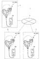
図3は、HMD100の外観構成を示す説明図である。
画像表示部20は、使用者の頭部に装着される装着体であり、本実施形態では眼鏡形状を有する。画像表示部20は、右保持部21と、右表示駆動部22と、左保持部23と、左表示駆動部24と、右光学像表示部26と、左光学像表示部28と、右カメラ61(撮像部)と、左カメラ62(撮像部)と、マイク63とを備える。右光学像表示部26及び左光学像表示部28は、それぞれ、使用者が画像表示部20を装着した際に使用者の右及び左の眼前に位置するように配置されている。右光学像表示部26の一端と左光学像表示部28の一端とは、使用者が画像表示部20を装着した際の使用者の眉間に対応する位置で、互いに連結されている。FIG. 3 is an explanatory diagram showing an external configuration of the
The
右保持部21は、右光学像表示部26の他端である端部ERから、使用者が画像表示部20を装着した際の使用者の側頭部に対応する位置にかけて、延伸して設けられた部材である。同様に、左保持部23は、左光学像表示部28の他端である端部ELから、使用者が画像表示部20を装着した際の使用者の側頭部に対応する位置にかけて、延伸して設けられた部材である。右保持部21及び左保持部23は、眼鏡のテンプル(つる)のようにして、使用者の頭部に画像表示部20を保持する。 The
右表示駆動部22と左表示駆動部24とは、使用者が画像表示部20を装着した際の使用者の頭部に対向する側に配置されている。なお、右表示駆動部22及び左表示駆動部24を総称して単に「表示駆動部」とも呼び、右光学像表示部26及び左光学像表示部28を総称して単に「光学像表示部」とも呼ぶ。 The right
表示駆動部22,24は、液晶ディスプレイ241,242(Liquid Crystal Display、以下「LCD241,242」と呼ぶ)、図4〜図6を参照して後述する投写光学系251,252等を含む。
右光学像表示部26及び左光学像表示部28は、導光板261,262(図4)と、調光板20Aとを備える。導光板261,262は、光透過性の樹脂等によって形成され、表示駆動部22,24が出力する画像光を、使用者の眼に導く。調光板20Aは、薄板状の光学素子であり、使用者の眼の側とは反対の側である画像表示部20の表側を覆うように配置される。調光板20Aは、光透過性がほぼ無いもの、透明に近いもの、光量を減衰させて光を透過するもの、特定の波長の光を減衰又は反射するもの等、種々のものを用いることができる。調光板20Aの光学特性(光透過率など)を適宜選択することにより、外部から右光学像表示部26及び左光学像表示部28に入射する外光量を調整して、虚像の視認のしやすさを調整できる。本実施形態では、少なくとも、HMD100を装着した使用者が外の景色を視認できる程度の光透過性を有する調光板20Aを用いる場合について説明する。調光板20Aは、右導光板261及び左導光板262を保護し、右導光板261及び左導光板262の損傷や汚れの付着等を抑制する。
調光板20Aは、右光学像表示部26及び左光学像表示部28に対し着脱可能としてもよく、複数種類の調光板20Aを交換して装着可能としてもよいし、省略してもよい。The
The right optical
The
右カメラ61は、HMD100の前面において右保持部21側の端部に配置される。また、左カメラ62は、HMD100の前面において左保持部23側の端部に配置される。右カメラ61、左カメラ62は、CCDやCMOS等の撮像素子及び撮像レンズ等を備えるデジタルカメラであり、単眼カメラであってもステレオカメラであってもよい。
右カメラ61及び左カメラ62は、HMD100の表側方向、換言すれば、HMD100を装着した状態における使用者の視界方向の少なくとも一部の外景を撮像する。別の表現では、右カメラ61及び左カメラ62の少なくとも一方は、使用者の視界と重なる範囲または方向を撮像する。より詳細には、右カメラ61及び左カメラ62の少なくとも一方は、使用者が注視する方向を撮像する。右カメラ61及び左カメラ62の画角の広さは適宜設定可能であるが、本実施形態では、後述するように、使用者が右光学像表示部26、左光学像表示部28を通して視認する外界を含む画角である。さらに、調光板20Aを通した使用者の視界の全体を撮像できるように右カメラ61、左カメラ62の撮像範囲が設定されているとより好ましい。
右カメラ61及び左カメラ62は、制御部140が備える撮像制御部161(図6)の制御に従って撮像を実行し、撮像画像データを撮像制御部161に出力する。The
The
The
距離センサー64は、右光学像表示部26と左光学像表示部28との境目部分に配置される。使用者が画像表示部20を装着した状態で、距離センサー64の位置は、水平方向においては使用者の両眼のほぼ中間であり、鉛直方向においては使用者の両眼より上である。
距離センサー64は、予め設定された測定方向に位置する測定対象物までの距離を検出する。距離センサー64は、例えば、LEDやレーザーダイオード等の光源と、光源が発する光が測定対象物に反射する反射光を受光する受光部とを有する。この場合、距離センサー64は、制御部140の制御に従い、三角測距処理や時間差に基づく測距処理を実行する。また、距離センサー64は、超音波を発する音源と、測定対象物で反射する超音波を受信する検出部とを備える構成としてもよい。この場合、距離センサー64は、制御部140の制御に従い、超音波の反射までの時間差に基づき測距処理を実行する。なお、距離センサー64は光源や受光部、或いは音源と検出部とを備え、測距処理を制御部140が行ってもよい。
本実施形態の距離センサー64の測定方向は、HMD100の表側方向であり、右カメラ61及び左カメラ62の撮像方向と重複する。The
The
The measurement direction of the
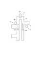
図4は、画像表示部20が備える光学系の構成を示す要部平面図である。図4には説明のため使用者の左眼LE及び右眼REを図示する。
左表示駆動部24は、LED等の光源と拡散板とを有する左バックライト222、左バックライト222の拡散板から発せられる光の光路上に配置される透過型の左LCD242を備える。また、左LCD242を透過した画像光Lを導くレンズ群等を備えた左投写光学系252を備える。左LCD242は、複数の画素をマトリクス状に配置した透過型液晶パネルである。FIG. 4 is a main-portion plan view showing the configuration of the optical system included in the
The left
左投写光学系252は、左LCD242から射出された画像光Lを並行状態の光束にするコリメートレンズを有する。コリメートレンズにより並行状態の光束にされた画像光Lは、左導光板262に入射される。左導光板262は、画像光Lを反射する複数の反射面が形成されたプリズムであり、画像光Lは、左導光板262の内部において複数回の反射を経て左眼LE側に導かれる。左導光板262には、左眼LEの眼前に位置するハーフミラー262A(反射面)が形成される。
ハーフミラー262Aで反射した画像光Lは左眼LEに向けて左光学像表示部28から射出され、この画像光Lが左眼LEの網膜に像を結び、使用者に画像を視認させる。The left projection
The image light L reflected by the
右表示駆動部22は、左表示駆動部24と左右対称に構成される。右表示駆動部22は、LED等の光源と拡散板とを有する右バックライト221、右バックライト221の拡散板から発せられる光の光路上に配置される透過型の右LCD241を備える。また、右LCD241を透過した画像光Lを導くレンズ群等を備えた右投写光学系251を備える。右LCD241は、複数の画素をマトリクス状に配置した透過型液晶パネルである。 The right
右投写光学系251は、右LCD241から射出された画像光Lを並行状態の光束にするコリメートレンズを有する。コリメートレンズにより並行状態の光束にされた画像光Lは、右導光板261に入射される。右導光板261は、画像光Lを反射する複数の反射面が形成されたプリズムであり、画像光Lは、右導光板261の内部において複数回の反射を経て右眼RE側に導かれる。右導光板261には、右眼REの眼前に位置するハーフミラー261A(反射面)が形成される。
ハーフミラー261Aで反射した画像光Lは右眼REに向けて右光学像表示部26から射出され、この画像光Lが右眼REの網膜に像を結び、使用者に画像を視認させる。The right projection
The image light L reflected by the
使用者の右眼REには、ハーフミラー261Aで反射した画像光Lと、調光板20Aを透過した外光OLとが入射する。左眼LEには、ハーフミラー262Aで反射した画像光Lと、調光板20Aを透過した外光OLとが入射する。このように、HMD100は、内部で処理した画像の画像光Lと外光OLとを重ねて使用者の眼に入射させ、使用者にとっては、調光板20Aを透かして外景が見え、この外景に重ねて、画像光Lによる画像が視認される。このように、HMD100は、シースルー型の表示装置として機能する。 The image light L reflected by the
なお、左投写光学系252と左導光板262とを総称して「左導光部」とも呼び、右投写光学系251と右導光板261とを総称して「右導光部」と呼ぶ。右導光部及び左導光部の構成は上記の例に限定されず、画像光を用いて使用者の眼前に虚像を形成する限りにおいて任意の方式を用いることができ、例えば、回折格子を用いても良いし、半透過反射膜を用いても良い。 The left projection
画像表示部20は、制御装置10に接続部40を介して接続する。接続部40は、制御装置10に接続される本体コード48、右コード42、左コード44、及び、連結部材46を備える。右コード42及び左コード44は、本体コード48が2本に分岐したコードである。右コード42は、右保持部21の延伸方向の先端部APから右保持部21の筐体内に挿入され、右表示駆動部22に接続される。同様に、左コード44は、左保持部23の延伸方向の先端部APから左保持部23の筐体内に挿入され、左表示駆動部24に接続される。 The
連結部材46は、本体コード48と、右コード42及び左コード44との分岐点に設けられ、イヤホンプラグ30を接続するためのジャックを有する。イヤホンプラグ30からは、右イヤホン32及び左イヤホン34が延伸する。イヤホンプラグ30の近傍にはマイク63が設けられる。イヤホンプラグ30からマイク63までは一本のコードにまとめられ、マイク63からコードが分岐して、右イヤホン32と左イヤホン34のそれぞれに繋がる。 The connecting
マイク63は、例えば図3に示すように、マイク63の集音部が使用者の視線方向を向くように配置され、音声を集音して、音声信号を音声処理部187(図6)に出力する。マイク63は、例えばモノラルマイクであってもステレオマイクであってもよく、指向性を有するマイクであってもよいし、無指向性のマイクであってもよい。 As shown in FIG. 3, for example, the
右コード42、左コード44、及び、本体コード48は、デジタルデータを伝送可能なものであればよく、例えば金属ケーブルや光ファイバーで構成できる。また、右コード42と左コード44とを一本のコードにまとめた構成としてもよい。 The
画像表示部20と制御装置10とは、接続部40を介して各種信号を伝送する。本体コード48の連結部材46とは反対側の端部、及び、制御装置10には、互いに嵌合するコネクター(図示略)が設けられる。本体コード48のコネクターと制御装置10のコネクターとを嵌合し、或いは、この嵌合を外すことで、制御装置10と画像表示部20とを接離できる。 The
制御装置10は、HMD100を制御する。制御装置10は、決定キー11、点灯部12、表示切替キー13、輝度切替キー15、方向キー16、メニューキー17、及び電源スイッチ18を含むスイッチ類を備える。また、制御装置10は、使用者が手指で操作するトラックパッド14を備える。 The
決定キー11は、押下操作を検出して、制御装置10で操作された内容を決定する信号を出力する。点灯部12は、LED(Light Emitting Diode)等の光源を備え、光源の点灯状態により、HMD100の動作状態(例えば、電源のON/OFF)を通知する。表示切替キー13は、押下操作に応じて、例えば、画像の表示モードの切り替えを指示する信号を出力する。 The
トラックパッド14は、接触操作を検出する操作面を有し、操作面に対する操作に応じて操作信号を出力する。操作面における検出方式は限定されず、静電式、圧力検出式、光学式等を採用できる。輝度切替キー15は、押下操作に応じて画像表示部20の輝度の増減を指示する信号を出力する。方向キー16は、上下左右方向に対応するキーへの押下操作に応じて操作信号を出力する。電源スイッチ18は、HMD100の電源オン/オフを切り替えるスイッチである。 The
図5は、画像表示部20の要部構成を示す図であり、(A)は画像表示部20を使用者の頭部側から見た要部斜視図、(B)は右カメラ61及び左カメラ62の画角の説明図である。なお、図5(A)では画像表示部20に繋がる右コード42、左コード44等の図示を省略する。 5A and 5B are diagrams showing the main configuration of the
図5(A)は、画像表示部20の使用者の頭部に接する側、言い換えれば使用者の右眼RE及び左眼LEに見える側である。別の言い方をすれば、右光学像表示部26及び左光学像表示部28の裏側が見えている。
図5(A)に示すように、HMD100は、ハーフミラー261A、及び、ハーフミラー262Aが使用者の眼に画像光を反射することによって、表示領域を形成する。HMD100はハーフミラー261A、262Aにより画像光を反射して使用者の眼に、虚像を認識させる。このため、本実施形態では、表示領域はハーフミラー261A、262Aそのものではなく、ハーフミラー261A、262Aに反射した画像光を使用者が知覚する領域である。なお、画像表示部20が、ハーフミラー261A、262Aに実際に画像を結像させる構成とした場合には、ハーフミラー261A、262Aが表示領域に相当する。表示領域は、右LCD241及び左LCD242に対応し、これらLCD241、242に表示される画像を使用者が視認する領域である。例えば、右LCD241及び左LCD242の表示可能な領域(表示可能領域)の全体に画像を表示すると、使用者に、表示領域の全体のサイズの画像を視認させることができる。FIG. 5A is a side of the
As shown in FIG. 5A, the
このように、使用者の右眼REに画像光を照射するハーフミラー261A、及び、左眼LEに画像光を照射するハーフミラー262Aにより、略四角形の表示画像が視認される。また、ハーフミラー261A、262Aを含む右光学像表示部26及び左光学像表示部28の全体が、上述したように外光を透過する。このため、使用者には、右光学像表示部26及び左光学像表示部28の全体を透過する外景と、ハーフミラー261A、262Aで反射される画像光で構成される表示画像とが、重なって視認される。 In this way, a substantially square display image is visually recognized by the
右カメラ61は、上記のように右保持部21側の端部に、画像表示部20の前方を向いて配置され、左カメラ62は、左保持部23側の端部に配置される。また、距離センサー64は、右光学像表示部26と左光学像表示部28との中央において、前方を向いて配置される。
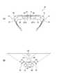
図5(B)は、右カメラ61、左カメラ62、及び距離センサー64の位置を、使用者の右眼RE及び左眼LEとともに平面視で模式的に示す図である。右カメラ61の画角(撮像範囲)をCR、左カメラ62の画角(撮像範囲)をCLで示す。なお、図3(B)には水平方向の画角CR、CLを示すが、右カメラ61及び左カメラ62の実際の画角は、一般的なデジタルカメラと同様に上下方向に拡がる。As described above, the
FIG. 5B is a diagram schematically showing the positions of the
画角CRと画角CLとは、画像表示部20の中央位置に対してほぼ左右対称であり、画角CRと画角CLは、いずれも画像表示部20の中央位置の真正面方向を含む。このため、画像表示部20の中央位置の正面で、画角CR、CLが重なる。
例えば、図5(B)に示すように、画像表示部20の正面方向に対象OBがある場合、対象OBは画角CR及び画角CLのどちらにも含まれる。このため、右カメラ61の撮像画像と、左カメラ62の撮像画像のいずれも、対象OBが写る。ここで、使用者が対象OBを注視すると、使用者の視線は、図中符号RD、LDに示すように対象OBに向けられる。一般に、人間の視野角は水平方向におよそ200度、垂直方向におよそ125度とされ、そのうち情報受容能力に優れる有効視野は水平方向に30度、垂直方向に20度程度である。さらに、人間が注視する注視点が迅速に安定して見える安定注視野は、水平方向に60〜90度、垂直方向に45度〜70度程度とされている。
従って、注視点が対象OBである場合、視線RD、LDを中心として水平方向に30度、垂直方向に20度程度が有効視野であり、水平方向に60〜90度、垂直方向に45度〜70度程度が安定注視野であり、水平方向に約200度、垂直方向に約125度が視野角となる。The angle of view CR and the angle of view CL are substantially symmetrical with respect to the central position of the
For example, as shown in FIG. 5B, when the target OB is in the front direction of the
Therefore, when the gazing point is the target OB, the effective visual field is about 30 degrees in the horizontal direction and about 20 degrees in the vertical direction about the lines of sight RD and LD, and the effective field of view is 60 to 90 degrees in the horizontal direction and 45 degrees in the vertical direction. A stable fixation field is about 70 degrees, and a viewing angle is about 200 degrees in the horizontal direction and about 125 degrees in the vertical direction.
また、HMD100を装着する使用者が画像表示部20を透過して右光学像表示部26及び左光学像表示部28を透過して視認する実際の視野を、実視野(FOV:Field Of View)と呼ぶ。本実施形態の構成で、実視野は、右光学像表示部26及び左光学像表示部28を透過して使用者が視認する実際の視野(後述する視野VR)に相当する。実視野は、図5(B)を参照して説明した視野角及び安定注視野より狭いが、有効視野より広い。 The actual field of view that a user wearing the
右カメラ61及び左カメラ62は、使用者の視野よりも広い範囲を撮像可能であることが好ましく、具体的には、画角CR、CLの全体が、少なくとも使用者の有効視野よりも広いことが好ましい。また、画角CR、CLの全体が、使用者の実視野よりも広いことが、より好ましい。さらに好ましくは、画角CR、CLの全体が、使用者の安定注視野よりも広く、最も好ましくは、画角CR、CLの全体が使用者の視野角よりも広い。 It is preferable that the
このため、右カメラ61及び左カメラ62は、画角CRと画角CLとが、図5(B)に示すように画像表示部20の前方で重なるように配置される。また、右カメラ61及び左カメラ62を広角カメラで構成してもよい。すなわち、右カメラ61及び左カメラ62が、撮像レンズとして、いわゆる広角レンズを備え、広い画角を撮像できる構成としてもよい。広角レンズには、超広角レンズ、準広角レンズと呼ばれるレンズを含んでもよいし、単焦点レンズであってもズームレンズであってもよく、複数のレンズからなるレンズ群を右カメラ61及び左カメラ62が備えてもよい。また、右カメラ61の画角CRと左カメラ62の画角CLとは同じ角度でなくてもよい。また、右カメラ61の撮像方向と左カメラ62の撮像方向とは、完全に平行である必要はない。右カメラ61の撮像画像と、左カメラ62の撮像画像とを重ね合わせた場合に、使用者の視野よりも広い範囲が撮像されていればよい。 Therefore, the
図5(B)には、距離センサー64の検出方向を符号64Aで示す。本実施形態で、距離センサー64は、画像表示部20の中央位置から正面方向に位置する物体までの距離を検出可能に構成され、例えば対象OBまでの距離を検出する。HMD100を装着した使用者は、注視する方向に頭を向けるため、注視する対象は画像表示部20の正面にあると考えることができる。このため、画像表示部20の中央に配置された距離センサー64が、画像表示部20の正面を検出方向64Aとすれば、使用者が注視する対象までの距離を検出できる。 In FIG. 5B, the detection direction of the
また、図5(A)に示すように、画像表示部20の使用者側には視線センサー68が配置される。視線センサー68は、使用者の右眼RE、及び、左眼LEのそれぞれに対応するように、右光学像表示部26と左光学像表示部28との中央位置に一対、設けられる。視線センサー68は、例えば、使用者の右眼REと左眼LEとをそれぞれ撮像する一対のカメラで構成される。視線センサー68は、制御部140(図6)の制御に従って撮像を行い、制御部140が、撮像画像データから右眼RE及び左眼LEの眼球表面における反射光や瞳孔の画像を検出し、視線方向を特定する。 Further, as shown in FIG. 5A, the line-of-
図6は、HMD100を構成する各部の機能ブロック図である。
HMD100は、コンテンツの供給元となる種々の外部機器OAを接続するインターフェイス125を備える。インターフェイス125は、例えば、USBインターフェイス、マイクロUSBインターフェイス、メモリーカード用インターフェイス等の有線接続に対応したインターフェイスを用いることができ、無線通信インターフェイスで構成してもよい。外部機器OAは、HMD100に画像を供給する画像供給装置であり、パーソナルコンピューター(PC)、携帯電話端末、携帯型ゲーム機等が用いられる。FIG. 6 is a functional block diagram of each unit constituting the
The
制御装置10は、制御部140、入力情報取得部110、記憶部120、送信部(Tx)51及び送信部(Tx)52を有する。
入力情報取得部110は、操作部135に接続される。操作部135は、上記のトラックパッド14、方向キー16、電源スイッチ18等を含み、入力情報取得部110は、操作部135から入力される信号に基づき、入力内容を取得する。また、制御装置10は、電源部(図示略)を備え、制御装置10及び画像表示部20の各部に電源を供給する。The
The input
記憶部120は、不揮発性の記憶装置であって、種々のコンピュータープログラム、および、これらのプログラムに係るデータを記憶する。また、記憶部120は、画像表示部20に表示する静止画像や動画像のデータを記憶しても良い。
記憶部120は、設定データ121を記憶する。設定データ121は、制御部140が使用する各種の設定値を含む。設定データ121が含む設定値は、予め操作部135の操作で入力された値であってもよいし、通信部117またはインターフェイス125を介して外部機器OAまたは他の装置(図示略)から設定値を受信して記憶してもよい。
また、記憶部120は、HMD100A、100B、100Cが送受信する各種のデータを記憶する。The
The
The
図7は、記憶部120が記憶するデータを模式的に示す図である。
記憶部120は、設定データ121、及び、送信先設定データ122を記憶する。また、記憶部120は、データを記憶する記憶領域として、送信データ記憶部126、及び、受信データ記憶部127を有する。送信データ記憶部126及び受信データ記憶部127は記憶部120の記憶領域を論理的あるいは仮想的に区切って設けることができ、例えばハードウェアとして区分される必要はない。FIG. 7 is a diagram schematically showing data stored in the
The
送信データ記憶部126は、HMD100が、他のHMD100に対して送信するデータを記憶する。つまり、送信データ記憶部126が記憶するデータは通信部117により、他のHMD100に送信される。一方、受信データ記憶部127は通信部117が受信したデータを記憶する。通信部117が受信するデータは、他のHMD100から通信ネットワーク4を経由して送信されたデータである。 The transmission
送信データ記憶部126は、送信用のデータとして、視界データ131、通知データ132、及び、動作案内データ133を記憶する。また、受信データ記憶部127は、通信部117が受信する視界データ131、通知データ132、動作案内データ133を記憶する。
送信データ記憶部126が記憶する視界データ131、通知データ132及び動作案内データ133は、それぞれ、受信データ記憶部127が記憶する視界データ131、通知データ132及び動作案内データ133と同一であってもよい。また、ヘッダー、属性、データフォーマット等が異なっていてもよい。The transmission
The
視界データ131は、右カメラ61及び左カメラ62の撮像画像データから一部を切り出したデータ、或いは撮像画像データの全体を含む画像データである。つまり、視界データ131は、使用者が見ている外界、すなわち視界の画像に相当する。視界データ131は静止画像データを含んでもよいし、動画像(映像)データを含んでもよく、音声データを含んでもよい。また、音声データを含み画像データを含まない構成としてもよい。HMD100は、視界データ131を送信することにより、使用者が見ている外界(視界)の画像を送信できる。また、HMD100は、他のHMD100から送信される視界データ131を再生し表示することで、他のHMD100の使用者が見ている視界を再現できる。 The
通知データ132は、HMD100において入力された内容を示すデータを含む。HMD100に対する入力は、後述するように、制御装置10の操作による入力、音声認識を利用した音声入力、画像表示部20に対するノック操作による入力、右カメラ61及び左カメラ62の撮像範囲に手等の指示体を写すことによるジェスチャー入力等である。通知データ132を送信することで、HMD100は、他のHMD100に対して入力内容を送信できる。また、他のHMD100から送信される通知データ132に基づく表示を行うことで、他のHMD100における入力の内容を知ることができる。 The
図8は、記憶部120に記憶されるデータの構成例を示す模式図であり、(A)は送信先設定データ122の例を示し、(B)は動作案内データ133の構成例を示す。
送信先設定データ122は、HMD100がデータを送信する送信先を定めるデータである。図1に示す表示システム1において、HMD100A、100B、100Cは、データを送信する送信先について、それぞれ異なる制約を設けることができる。例えば、HMD100Aは管理者UAが装着して使用し、HMD100B、100Cは作業者UB、UCが装着する。使用者が管理者や作業者かに応じて、データの送信先を設定できる。送信先設定データ122では、送信先となるHMD100を特定するIDと、送信するデータの種類とが対応付けて設定される。FIG. 8 is a schematic diagram showing a configuration example of data stored in the
The
図8(A)は、作業者UBが使用するHMD100Bが有する送信先設定データ122の例である。HMD100Bは、HMD100A(図中のID:0001)に対しては視界データ131及び通知データ132を送信できる。また、HMD100C(図中のID:0003)には通知データ132のみを送信できる。 FIG. 8A is an example of the
同様の設定として、例えば、HMD100Aが記憶する送信先設定データ122では、HMD100B、100Cに対して通知データを送信できるよう設定される。また、例えば、HMD100Cが記憶する送信先設定データ122では、HMD100Aに対して視界データ131と通知データ132を送信でき、HMD100Bに対して通知データ132を送信できる。
送信先設定データ122は、HMD100が記憶し送信するデータの一部について設定するデータであってもよい。例えば、後述する動作案内データ133は、送信先設定データ122の制約を受けず、表示システム1内の他のHMD100に送信可能な構成とすることができる。As a similar setting, for example, the transmission
The
動作案内データ133は、HMD100を装着する使用者に対して動作を案内する表示や音声出力を行うためのデータである。動作案内データ133は、図8(B)に示すように、動作の内容を案内する案内情報133a、動作の実行順を指定する順序情報133b、及び、動作の実行状態を示す状態情報133cを含む。 The
順序情報133bが示す動作の実行順序は、動作の相対的な順序であり、動作案内データ133が含む動作が一つの場合は順序が対応づけられなくてもよい。
動作案内データ133が含むそれぞれの動作は、項目(タイトル)が付され、図8(B)の例では順序情報133bを兼ねて作業1、作業2…の項目が付されている。動作とは、使用者が行う行動または行為を指し、使用者の身体の動きであってもよいし思考や判断を含んでもよい。動作案内データ133の一つの動作が、実際には複数の動作を含むシーケンスに対応してもよい。
案内情報133aは、動作を行う使用者に対して動作の内容の説明等を行うために出力されるテキスト、静止画像、映像、音声等を含む。The execution order of the operations indicated by the
Items (titles) are attached to the respective actions included in the
The
状態情報133cは、動作案内データ133に含まれる動作の実行の履歴に関するデータである。例えば、状態情報133cは、案内情報133aの進捗履歴や実行履歴に関するデータである。図8(B)の例では、状態情報133cは、動作が完了したことを示す「完了」、動作の実行が開始されてから完了するまでの間の状態を示す「実行中」および動作の実行が開始されていないことを示す「未実行」に設定される。
状態情報133cは、使用者の動作の進行に伴って変化する。後述するように、状態情報133cは、制御部140の制御により、動作の進行に伴って更新される。The
The
制御部140には、3軸センサー113、GPS115、通信部117及び音声認識部114が接続される。3軸センサー113は3軸の加速度センサーであり、制御部140は3軸センサー113の検出値を取得する。3軸センサー113により、制御部140は、制御装置10の動きを検出することができ、例えば制御装置10を振る等の操作を検出できる。また、3軸センサー113は9軸センサーに置き換えてもよい。この場合、制御部140は、3軸の加速度センサー、3軸の角速度センサー、及び3軸の地磁気センサーの検出値を取得し、例えば、制御装置10の姿勢、向き、動きを検出できる。
GPS115は、アンテナ(図示略)を備え、GPS(Global Positioning System)信号を受信し、制御装置10の現在位置を算出する。GPS115は、GPS信号に基づいて求めた現在位置や現在時刻を制御部140に出力する。また、GPS115はGPS信号に含まれる情報に基づいて現在時刻を取得し、制御部140が計時する時刻を修正させる機能を備えていてもよい。The
The
通信部117は、無線LAN(WiFi(登録商標))、Miracast(登録商標)、Bluetooth(登録商標)等の規格に準じた無線データ通信を実行する。
外部機器OAが、通信部117に無線接続された場合、制御部140は、コンテンツデータを通信部117より取得して、画像表示部20に画像を表示させる。一方、外部機器OAが、インターフェイス125に有線接続された場合、制御部140は、コンテンツデータをインターフェイス125より取得して、画像表示部20に画像を表示させる。通信部117及びインターフェイス125は、外部機器OAからコンテンツデータを取得するデータ取得部DAとして機能する。The
When the external device OA is wirelessly connected to the
制御部140は、プログラムを実行するCPU(図示略)、CPUが実行するプログラムやデータを一時的に格納するRAM(図示略)、及び、CPUが実行する基本制御プログラムやデータを不揮発的に記憶するROM(図示略)を備える。制御部140は、記憶部120が記憶するコンピュータープログラムを読み出して実行し、オペレーティングシステム(OS)150、画像処理部160として機能する。また、撮像制御部161、入力認識部162(認識部)、AR表示制御部163、状態検出部164、通信制御部165、判定部166、音声処理部187、及び、表示制御部190として機能する。 The
画像処理部160は、コンテンツに含まれる画像信号を取得する。画像処理部160は、取得した画像信号から、垂直同期信号VSyncや水平同期信号HSync等の同期信号を分離する。また、画像処理部160は、分離した垂直同期信号VSyncや水平同期信号HSyncの周期に応じて、PLL(Phase Locked Loop)回路等(図示略)を利用してクロック信号PCLKを生成する。画像処理部160は、同期信号が分離されたアナログ画像信号を、A/D変換回路等(図示略)を用いてディジタル画像信号に変換する。画像処理部160は、変換後のディジタル画像信号を、対象画像の画像データ(図中、Data)として、1フレームごとに、制御部140のRAMに格納する。この画像データは、例えばRGBデータである。
なお、画像処理部160は、必要に応じて、画像データの解像度を右表示駆動部22及び左表示駆動部24に適した解像度に変換する解像度変換処理を行ってもよい。また、画像処理部160は、画像データの輝度や彩度を調整する画像調整処理、3D画像データから2D画像データを作成し、或いは2D画像データから3D画像データを生成する2D/3D変換処理等を実行してもよい。The
The
画像処理部160は、クロック信号PCLK、垂直同期信号VSync、水平同期信号HSync、RAMに格納された画像データDataのそれぞれを、送信部51、52を介して送信する。送信部51、52は、トランシーバーとして機能し、制御装置10と画像表示部20との間におけるシリアル伝送を実行する。なお、送信部51を介して送信される画像データDataを「右眼用画像データ」と呼び、送信部52を介して送信される画像データDataを「左眼用画像データ」と呼ぶ。 The
表示制御部190は、右表示駆動部22及び左表示駆動部24を制御する制御信号を生成し、この制御信号により、右表示駆動部22及び左表示駆動部24のそれぞれによる画像光の生成及び射出を制御する。具体的には、右LCD制御部211による右LCD241の駆動ON/OFF、右バックライト制御部201による右バックライト221の駆動ON/OFFを制御する。また、表示制御部190は、左LCD制御部212による左LCD242の駆動ON/OFF、左バックライト制御部202による左バックライト222の駆動ON/OFFを制御する。 The
音声処理部187は、コンテンツに含まれる音声信号を取得し、取得した音声信号を増幅して、右イヤホン32および左イヤホン34に出力する。また、音声処理部187は、マイク63により集音される音声を取得してディジタル音声データに変換する。音声処理部187は、ディジタル音声データに対して予め設定された処理を行ってもよい。 The
画像表示部20は、上記の右カメラ61、左カメラ62、及び距離センサー64を備える。また、画像表示部20は、インターフェイス25と、右表示駆動部22と、左表示駆動部24と、右光学像表示部26としての右導光板261と、左光学像表示部28としての左導光板262と、9軸センサー66と、視線センサー68とを備える。 The
9軸センサー66(動き検出部)は、加速度(3軸)、角速度(3軸)、地磁気(3軸)を検出するモーションセンサーである。制御部140は、画像表示部20が使用者の頭部に装着されているとき、9軸センサー66の検出値に基づいて使用者の頭部の動きを検出できる。例えば、制御部140は、9軸センサー66の検出値に基づき、画像表示部20の傾きの大きさと傾きの向きを推定できる。 The 9-axis sensor 66 (motion detection unit) is a motion sensor that detects acceleration (3 axes), angular velocity (3 axes), and geomagnetism (3 axes). The
インターフェイス25は、右コード42と左コード44とが接続されるコネクターを備える。インターフェイス25は、送信部51から送信されるクロック信号PCLK、垂直同期信号VSync、水平同期信号HSync、画像データDataを、対応する受信部(Rx)53、54に出力する。また、インターフェイス25は、表示制御部190から送信される制御信号を、対応する受信部53、54、右バックライト制御部201又は左バックライト制御部202に出力する。
また、インターフェイス25は、右カメラ61、左カメラ62、距離センサー64、9軸センサー66及び視線センサー68を接続するインターフェイスである。右カメラ61、左カメラ62の撮像データ、距離センサー64の検出結果、9軸センサー66による加速度(3軸)、角速度(3軸)、地磁気(3軸)の検出結果、及び、視線センサー68の検出結果は、インターフェイス25を介して制御部140に送られる。The
The
右表示駆動部22は、上述した右バックライト221、右LCD241、及び右投写光学系251を備える。また、右表示駆動部22は、受信部53、右バックライト(BL)221を制御する右バックライト(BL)制御部201、及び、右LCD241を駆動する右LCD制御部211を備える。 The right
受信部53は、送信部51に対応するレシーバーとして動作し、制御装置10と画像表示部20との間におけるシリアル伝送を実行する。右バックライト制御部201は、入力された制御信号に基づいて、右バックライト221を駆動する。右LCD制御部211は、受信部53を介して入力されたクロック信号PCLKと、垂直同期信号VSyncと、水平同期信号HSyncと、右眼用画像データDataと、に基づいて、右LCD241を駆動する。 The receiving
左表示駆動部24は、右表示駆動部22と同様の構成を有する。左表示駆動部24は、上述した左バックライト222、左LCD242、及び左投写光学系252を備える。また、左表示駆動部24は、受信部54、左バックライト222を駆動する左バックライト制御部202、及び、左LCD242を駆動する左LCD制御部212を備える。 The left
受信部54は、送信部52に対応するレシーバーとして動作し、制御装置10と画像表示部20との間におけるシリアル伝送を実行する。左バックライト制御部202は、入力された制御信号に基づいて、左バックライト222を駆動する。左LCD制御部212は、受信部54を介して入力されたクロック信号PCLKと、垂直同期信号VSyncと、水平同期信号HSyncと、右眼用画像データDataと、に基づいて、左LCD242を駆動する。
なお、右バックライト制御部201と、右LCD制御部211と、右バックライト221と、右LCD241とを総称して、右の「画像光生成部」とも呼ぶ。同様に、左バックライト制御部202と、左LCD制御部212と、左バックライト222と、左LCD242とを総称して、左の「画像光生成部」とも呼ぶ。The receiving
The right
撮像制御部161は、右カメラ61及び左カメラ62を制御して撮像を実行させ、撮像画像データを取得する。撮像制御部161は、右カメラ61及び左カメラ62のいずれか一方にのみ撮像を実行させてもよいし、両方に撮像を実行させてもよい。 The
入力認識部162は、HMD100に対する入力を検出し、認識する。入力認識部162は、入力情報取得部110から入力される信号に基づいて、操作部135に対する操作を検出する。また、入力認識部162は、マイク63で集音された音声を音声処理部187が解析し、予め設定された音声コマンドであると判定された場合に、この音声コマンドの入力を検出する。また、入力認識部162は、右カメラ61及び/又は左カメラ62の撮像画像から、使用者の手等の指示体の画像を検出し、この指示体の位置、方向、或いは動きが予め設定されたジェスチャーに相当すると判定した場合に、ジェスチャー入力を検出する。また、入力認識部162は、画像表示部20が備える9軸センサー66の検出値のパターンが、画像表示部20をノックする操作に該当すると判定した場合に、画像表示部20に対するノック操作を入力として検出する。また、入力認識部162は、右カメラ61及び/又は左カメラ62の撮像画像から、二次元コードやバーコード等の入力用マーカーの画像を検出した場合に、マーカー読取入力を検出する。入力認識部162は、右カメラ61及び/または左カメラ62の撮像画像データから、指示体やマーカーを検出する場合に、視線センサー68により検出される使用者の視線方向に対応する指示体やマーカーを検出してもよい。 The
また、HMD100は、使用者が足で操作するフットスイッチ(図示略)を備えた構成としてもよい。フットスイッチは制御部140または操作部135に有線接続されてもよいし、Bluetooth(登録商標)等の無線通信により通信部117に接続されてもよい。この場合、入力認識部162は、フットスイッチの操作を検出して入力として認識する。 Further, the
AR表示制御部163は、記憶部120が記憶するデータを読み出し、画像処理部160及び表示制御部170を制御して、画像やテキストを画像表示部20により表示させる。ここで、AR表示制御部163は、画像やテキストを、使用者の視野に存在する実空間の対象の位置に合わせて、AR表示してもよいし、3D(立体)表示してもよく、2D(平面)表示してもよい。また、AR表示制御部163は記憶部120から読み出したデータに基づき、音声処理部187を制御して、右イヤホン32、左イヤホン34から音声を出力させてもよい。 The AR
具体的には、AR表示制御部163は、受信データ記憶部127に記憶される視界データ131に基づいて、他のHMD100の使用者の視界の静止画像または映像を表示する。ここで、音声を出力させてもよい。
また、AR表示制御部163は、受信データ記憶部127の動作案内データ133を読み出し、この動作案内データ133に基づいて、動作を案内する静止画像、動画像、テキスト等を表示する。ここで、AR表示制御部163は、複数の動作に対応する案内情報133aを、順序情報133bで規定される順序に従って並べてリスト形式で、表示してもよい。また、案内情報133aを、1つずつまたは設定された数ずつ、順序情報133bで規定される順序に従って、切り替えて表示してもよい。Specifically, the AR
Further, the AR
状態検出部164は、AR表示制御部163が動作案内データ133に基づく表示を行う間に、動作案内データ133の案内情報133aに対応する動作(作業)の実行状態を検出する。
状態検出部164が実行状態を検出する処理は、例えば、右カメラ61及び/又は左カメラ62の撮像画像データを解析して行われる。この場合、状態検出部164は撮像画像データから動作の対象や、動作に使用される器具、道具、使用者の身体等の少なくともいずれかを検出する。状態検出部164は、動作の対象、動作に使用される器具、道具、使用者の身体等の位置、サイズ、色、形状等に基づいて、動作の実行状態に関するデータを生成する。The
The process of detecting the execution state by the
また、状態検出部164は、動作案内データ133の項目についてAR表示制御部163が表示する状態で、入力認識部162が検出する入力に基づき、項目に対応する動作の実行状態を検出してもよい。 Further, the
入力認識部162が、右カメラ61及び/または左カメラ62の撮像画像データから、指示体やマーカーを検出する場合、予め設定された特徴量を使用してもよい。状態検出部164が右カメラ61及び/または左カメラ62の撮像画像データから動作の対象、動作に使用される器具、道具、使用者の身体等の位置、サイズ、色、形状等を検出する場合も同様である。この特徴量は、撮像画像から画像を検出する処理に用いるデータであり、画像の特徴量等である。例えば、物体である対象物を検出する場合に、この物体を撮像した場合の撮像画像の色、形状、その他の特徴を示す特徴量が設定データに含まれる。この場合、入力認識部162、状態検出部164は、外景画像の画像データから物体の画像を抽出する処理を行い、抽出した物体の画像の特徴量を算出し、算出した特徴量と、設定データ121に含まれる特徴量とを比較照合する。特徴量が近い値であり、或いは同一である場合は、外景画像から抽出した画像の物体を対象物として認識できる。また、対象物について複数の特徴量が設定データ121に含まれる場合、入力認識部162、状態検出部164は複数の特徴量に基づき外景画像から対象物を検出し、認識できる。 When the
なお、入力認識部162や状態検出部164が画像から対象や指示体を認識する方法は、上記のように画像の特徴量に基づき対象物の画像を認識する方法に限定されない。例えば、使用者の指示により、外景画像に含まれる物体等から対象や指示体を選択してもよい。この場合、使用者の指示は、音声による指示であってもよく、マイク63で集音された音声を音声処理部187がテキスト変換することにより、入力認識部162や状態検出部164が対象を認識し、特定するための情報を取得する。例えば、色や対象の形状など、撮像画像における対象物の特徴を指定する音声がテキスト変換された場合に、入力認識部162、状態検出部164は、指定された特徴に該当する画像を撮像画像から検出して、認識する。対象物に関する情報の入力方法は、上述したように、入力認識部162が検出可能な入力を利用できる。 The method of recognizing the target or the indicator from the image by the
判定部166は、HMD100の使用者の状態を判定する。より具体的には、使用者の状態が、HMD100から他のHMD100へ通知データ132を送信すべき状態に該当するか否かを判定する。通知データ132を送信すべき状態と判定する基準、或いは条件は、予め設定され、例えば記憶部120に設定データとして記憶される。例えば、入力認識部162が所定の入力を検出し認識したことを、判定基準とすることができる。この場合、判定部166は、入力認識部162が予め設定された条件に該当する入力を認識した場合に、使用者の状態が、通知データ132を送信すべき状態であると判定する。 The
判定部166が判定に利用する基準、或いは条件は、入力認識部162が認識する入力に関する内容に限定されない。例えば、判定部166は、9軸センサー66の検出値に基づいて使用者の頭部または身体の動きが予め設定された動きに該当するか否かを判定してもよい。また、視線センサー68の検出値に基づいて使用者の視線の動きが予め設定された動きに該当するか否かを判定してもよい。また、筋電計(図示略)、脈拍測定装置(図示略)、血圧測定装置(図示略)、血中酸素濃度測定装置(図示略)等のバイタルセンサーをHMD100に設け、これらのバイタルセンサーの測定値、検出値に基づき判定を行ってもよい。これらの場合、使用者が通知データ132の送信を意図していなくても、使用者の身体の状態を判定できる。例えば、使用者が、通知データ132の送信を希望していながら、入力認識部162が認識し得る入力を行うことができない状態である場合に、判定部166が使用者の状態を判定できる。
さらに、判定部166が、入力認識部162が認識する入力、9軸センサー66や視線センサー68の検出値、及び、バイタルセンサーの検出値について、学習を実行し、使用者の状態に関する判定の基準または条件を設定あるいは変更してもよい。この学習は、判定部166がAI(Artificial Intelligence:人工知能)エンジンを有し、自律的に学習を行ってもよい。また、予め判定部166に設定されるアルゴリズムに従って、判定部166が、判定の基準あるいは条件を最適化してもよい。The criterion or condition used by the
Further, the
図2に示した例で、作業者UBの作業に支障が発生した場合、作業者UBは管理者UAまたは作業者UCに通知データ132を送信することが適切であるが、作業者UBが、支障を解消する作業に気を取られて、HMD100の操作を行えない可能性がある。この場合、作業者UBの状態を判定することで、ラインにおける問題の発生の検出、及び、問題発生箇所の特定をすることができる。そして、他の作業者や管理者による援助等の対処が可能となる。そして、通知データ132を送信するとともに、右カメラ61及び/又は左カメラ62の撮像画像を送信することにより、発生した問題の状況を、当事者である作業者UB以外の管理者UAや作業者UCが、速やかに確認できる。 In the example shown in FIG. 2, when the work of the worker UB is hindered, it is appropriate that the worker UB sends the
通信制御部165は、通信部117を制御して、通信ネットワーク4に接続される無線アクセスポイント(図示略)等との間の無線通信を実行させる。
なお、表示システム1を構成する複数のHMD100が互いに近接した位置にある場合、すなわち、複数のHMD100が、相互に通信部117が無線信号を送受信可能な範囲内にある場合、通信ネットワーク4を経由せずに、直接、通信部117と通信部117との間で無線通信を行ってもよい。The
In addition, when the plurality of
図9は、表示システム1の動作を示すフローチャートである。
以下の説明では図1及び図2に示したように、作業を管理する管理者UAがHMD100Aを装着して使用し、作業者UBがHMD100Bを装着して使用し、作業者UCがHMD100Cを装着して使用する例を説明する。
図9(A)はHMD100Bの動作を示し、図9(B)はHMD100Aの動作を示す。FIG. 9 is a flowchart showing the operation of the
In the following description, as shown in FIGS. 1 and 2, the administrator UA who manages the work wears and uses the
9A shows the operation of the
作業を開始するにあたり、HMD100Aでは動作開始の指示が入力され(ステップS31)、HMD100Bでも動作開始の指示が入力される(ステップS11)。
HMD100Aは、予め送信データ記憶部126に記憶された動作案内データ133を送信し(ステップS32)、HMD100Bは動作案内データ133を受信して受信データ記憶部127に記憶する(ステップS12)。When starting the work, the operation start instruction is input in the
The
HMD100BのAR表示制御部163は、受信データ記憶部127の動作案内データ133に基づいて、静止画像、動画像、テキスト等の表示及び/又は音声の出力等を開始する(ステップS13)。これにより、HMD100Bを装着する作業者UBは動作案内データ133に基づく案内に従って、対象OB(図2)に対する作業を行える。 The AR
また、HMD100Bの入力認識部162は、作業開始に合わせて、右カメラ61及び/又は左カメラ62による撮像と、音声処理部187による音声検出を開始する(ステップS14)。 In addition, the
HMD100Bは、入力認識部162の機能により、右カメラ61及び/又は左カメラ62の撮像画像データから視界データ131を生成し、送信データ記憶部126に記憶し、この視界データ131をHMD100Aに送信する(ステップS15)。視界データ131の生成及び送信の周期は、動作案内データ133や設定データ121に含まれるデータで指定される。 The
入力認識部162は、入力の検出の有無を判定する(ステップS17)。入力を検出した場合(ステップS17;YES)、入力認識部162は入力内容に対応する通知データ132を生成して送信データ記憶部126に記憶し、HMD100Aに送信し(ステップS18)、ステップS19に移行する。また、入力が無いと判定した場合(ステップS17;NO)、入力認識部162はステップS19に移行する。 The
ステップS19で、状態検出部164は、動作状態が変化したか否かを判定する(ステップS19)。動作が開始された場合、動作が完了した場合など、動作状態が変化した場合(ステップS19;YES)、状態検出部164は、受信データ記憶部127に記憶した動作案内データ133の状態情報133cを更新し(ステップS20)、ステップS21に移行する。また、動作状態が変化しない場合(ステップS19;NO)、ステップS21に移行する。 In step S19, the
HMD100Aは、HMD100Bから視界データ131が送信された場合に、この視界データ131を受信して受信データ記憶部127に記憶する(ステップS34)。HMD100AのAR表示制御部163は、受信した視界データ131に基づき、HMD100Bの作業者UBの視界に相当する静止画像、動画像、音声等を出力する(ステップS35)。 When the
また、HMD100Aは、HMD100Bから通知データ132が送信された場合に、この通知データ132を受信して受信データ記憶部127に記憶する(ステップS36)。HMD100AのAR表示制御部163は、受信した通知データ132に基づき、HMD100Bにおける入力内容を示すテキスト、静止画像、動画像、音声等を出力する(ステップS37)。 In addition, when the
HMD100Aの入力認識部162は、入力の検出の有無を判定する(ステップS38)。入力を検出した場合(ステップS38;YES)、入力認識部162は入力内容に対応する通知データ132を生成して送信データ記憶部126に記憶し、HMD100Bに送信し(ステップS39)、ステップS40に移行する。また、入力が無いと判定した場合(ステップS38;NO)、入力認識部162はステップS40に移行する。 The
ステップS39で、HMD100Aの入力認識部162は、通知データ132を複数のHMD100B、100Cに同時に送信してもよい。この場合、複数のHMD100B、100Cに同じ通知データ132を送信してもよいし、異なる通知データ132を生成して送信してもよい。送信先は、その度、管理者UAの入力により指定してもよいし、送信先設定データ122により従って決定してもよい。 In step S39, the
ステップS23で、HMD100Bの制御部140は、終了の条件が成立したか否かを判定する(ステップS23)。終了の条件は、ステップS12で受信した動作案内データ133に含まれる全ての動作が完了した場合、入力認識部162により終了の指示の入力を検出した場合等である。終了の条件が成立しない場合(ステップS23;NO)、制御部140はステップS15に戻る。また、終了の条件が成立した場合(ステップS23;YES)、制御部140は本処理を終了する。処理の終了時に、制御部140は、受信データ記憶部127に記憶した動作案内データ133を、送信データ記憶部126にコピーして、HMD100Aに送信してもよい。また、動作を終了することをHMD100Aに通知する通知データ132を送信してもよい。 In step S23, the
ステップS40で、HMD100Aの制御部140は、終了の条件が成立したか否かを判定する(ステップS40)。終了の条件は、HMD100Bから動作を終了することが通知された場合、入力認識部162により終了の指示の入力を検出した場合等である。終了の条件が成立しない場合(ステップS40;NO)、制御部140はステップS34に戻る。また、終了の条件が成立した場合(ステップS40;YES)、制御部140は本処理を終了する。なお、処理の終了時に、制御部140は、表示システム1に含まれる他の全てのHMD100に対して、終了を通知する通知データ132を送信してもよい。この場合、管理者UAが使用するHMD100A以外のHMD100が、HMD100Aから終了を通知する通知データ132を受信した場合に動作を終了するよう設定されていてもよい。 In step S40, the
なお、図9(A)に示すフローチャートでは、HMD100Bで入力を検出し(ステップS17)、動作状態の変化を検出し(ステップS19)、通知データ132を受信し(ステップS21)、終了を判定する(ステップS23)処理を、各ステップで順次行う構成とした。本発明はこれに限定されず、上述した各ステップの動作は、割り込み処理としてもよい。つまり、HMD100Bの制御部140は、ステップS11で動作を開始した後、入力の検出(ステップS17)、動作状態の変化の検出(ステップS19)、通知データ132の受信(ステップS21)、終了の指示(ステップS23)を待機する。そして、入力や動作を検出した場合に、ステップS17、S19、S21、S23の動作を割り込み処理として開始してもよい。図9(B)のステップS34、S38、S39、S40も同様である。 In the flowchart shown in FIG. 9A, the
図10は、表示システム1の動作を示すフローチャートであり、動作を実行する作業者UB、UCが使用するHMD100B、100Cの間で、動作に関するデータを引き継ぐ動作を示す。図10(A)はHMD100Bの動作を示し、図10(B)はHMD100Cを示し、HMD100BからHMD100Cに動作を引き継ぐ例を示す。
図10の動作は、HMD100Bが動作案内データ133に従って動作を実行する間、すなわち、図9(A)のステップS13〜S23の間に実行される。FIG. 10 is a flowchart showing the operation of the
The operation of FIG. 10 is executed while the
HMD100Bの入力認識部162は、動作引継を指示する入力を検出し(ステップS51)、動作を引き継ぐHMD100に対する動作の引継要請の入力を検出する(ステップS52)。入力認識部162は、動作の引継の要請に関する入力内容に基づき、通知データ132を生成して送信データ記憶部126に記憶し、HMD100Cに送信する(ステップS53)。 The
HMD100CのAR表示制御部163は、HMD100Bから通知データ132を受信して受信データ記憶部127に記憶し(ステップS61)、受信した通知データ132に基づきテキスト、静止画像、映像、音声等を出力する(ステップS62)。 The AR
HMD100Bの制御部140は、受信データ記憶部127に記憶した動作案内データ133を送信データ記憶部126にコピーして、HMD100Bに送信する(ステップS54)。この動作案内データ133は、受信データ記憶部127に記憶されHMD100Bにおける動作の進行に伴って更新されたデータである。
HMD100Cの制御部140は、動作案内データ133を受信して受信データ記憶部127に記憶する(ステップS63)。AR表示制御部163は、動作案内データ133を受信したことの通知を生成してHMD100Bに送信し(ステップS64)、受信した動作案内データ133に基づいて、静止画像、動画像、テキスト等の表示及び/又は音声の出力等を開始する(ステップS65)。ここで、AR表示制御部163は、受信した動作案内データ133に含まれる状態情報133cに従って、実行中または未実行の動作から、案内情報133aを出力する。従って、HMD100Cを装着する作業者UCは、HMD100Bを装着する作業者UBが実行した動作の続きから、動作案内データ133に基づく案内に従って対象OB(図2)に対する作業を行える。The
The
また、HMD100Bの制御部140は、HMD100Cから動作案内データ133の受信に関する通知を受信し(ステップS55)、本処理を終了する。ここで、HMD100Bの制御部140は、受信データ記憶部127に記憶した動作案内データ133を消去してもよい。また、送信データ記憶部126に記憶した動作案内データ133も消去してもよい。これにより、複数のHMD100が重複して保持されなくなるので、動作の混乱を避けることができる。
なお、ステップS11、S12における動作引継の指示、及び要請の入力は、HMD100Aにおいて行ってもよい。この場合、動作引継を指示する通知データ132が、HMD100Aから、HMD100B及びHMD100Cに送信され、この通知データ132に従ってHMD100BとHMD100Cが図10の動作を開始すればよい。Further, the
The operation takeover instruction and the request input in steps S11 and S12 may be performed by the
図11は、表示システムにおける表示例を示す図である。図11(A)はHMD100B、100Cが作業者UB、UCに対して表示する例を示し、図11(B)はHMD100B、100Cが作業者UB、UCに対して表示する別の例を示す。図11(C)はHMD100Aにおいて表示される例を示す。
図11(A)〜(C)では、VRは使用者(管理者UA、作業者UB、UC)の視野を示し、V1は、HMD100が画像を表示して使用者に視認させることが可能な領域、すなわち画像表示部20の表示領域を示す。表示領域V1は、たとえば、使用者の視野VRのほぼ中央に位置し、視野VRよりも狭い。表示領域V1は視野VRと同じサイズであってもよく、サイズ及び位置は図11(A)〜(C)の例に限定されない。FIG. 11 is a diagram showing a display example in the display system. FIG. 11A shows an example displayed by the
In FIGS. 11A to 11C, VR indicates the field of view of the user (administrator UA, worker UB, UC), and V1 allows the
図11(A)では、AR表示制御部163は、動作案内データ133の案内情報133aを一覧表示するリストSRを表示する。リストSRは、動作案内データ133に含まれる案内情報133aを、順序情報133bで指定される順序に従って並べたリストである。リストSRには、案内情報133aのタイトルと内容を表示してもよい。また、順序情報133bで指定される順序を表示してもよい。
リストSRには、案内情報133aの表示位置に対応づけて、チェックボックスCHが配置される。チェックボックスCHは、動作案内データ133の動作が完了したことを示す。AR表示制御部163は、状態検出部164が動作の完了を検出した場合に、チェックボックスCHの表示状態を、動作完了を示す状態に変更する。これに伴い、状態検出部164は、受信データ記憶部127の動作案内データ133において状態情報133cを更新すればよい。動作案内データ133が含む案内情報133aが1つの場合、リストSRは一つの動作の内容とチェックボックスCHとを含む構成となる。In FIG. 11A, the AR
A check box CH is arranged in the list SR in association with the display position of the
リストSRは、チェックボックスCHを有しない構成とすることもできる。この場合、AR表示制御部163は、状態検出部164により動作が完了したことが検出された項目を、リストSRから削除してもよい。また、リストSRにおける表示色や表示輝度を変化させてもよい。 The list SR may be configured without the check box CH. In this case, the AR
図7(B)の例は、動作案内データ133の案内情報133aを一つ、または予め設定された数ずつ表示する例である。この例では、表示領域V1に、案内情報133aを1つずつ、吹き出し形式の表示部Dに表示する。表示部Dの端部を、対象OBにおいて動作の対象となる位置を示す矢印形式としてもよい。また、表示部Dに表示された案内情報133aに対応する動作の対象の位置に、マーカーMを表示してもよい。図11(B)の例では、表示部Dに表示された案内情報133aに対応する動作が完了したことが状態検出部164により検出されると、AR表示制御部163は、動作案内データ133に含まれる次の順序の案内情報133aを表示部Dに表示する。このように、表示部Dには、案内情報133aが、項目の動作の実行順に従って、順次、表示される。 The example of FIG. 7B is an example in which the
リストSRや表示部Dの表示位置、表示態様は、適宜に変更可能であり、例えば、リストSRや表示部Dを、動作案内データ133の項目に対応する動作の対象OBに重なる位置に表示してもよい。また、対象OBに重ならない位置に表示すれば、動作の妨げにならず、項目を見ながら動作しやすくなるという利点がある。また、リストSRや表示部Dを3D(立体)表示してもよいし、2D(平面)画像として表示してもよい。さらに、リストSRや表示部Dを、右表示駆動部22と左表示駆動部24のいずれか一方にのみ表示してもよい。 The display position and display mode of the list SR and the display unit D can be changed as appropriate. For example, the list SR and the display unit D are displayed at a position overlapping the target OB of the motion corresponding to the item of the
また、図11(A)、(B)では、表示領域V1に、視線センサー68により検出した使用者の視線方向を示すポインターPを表示してもよい。 In addition, in FIGS. 11A and 11B, a pointer P indicating the line-of-sight direction of the user detected by the line-of-
図11(C)の例は、HMD100Aが、HMD100B、100Cから送信される視界データ131に基づく静止画像を表示する例である。表示領域V1には、HMD100Bの視界データ131に基づく視界表示VW1と、HMD100Cの視界データ131に基づく視界表示VW2とが並べて表示される。視界表示VW1、VW2には、それぞれ、送信元のHMD100B、100Cを示すIDが対応付けて表示される。この場合、管理者UAは、作業者UB、UCの視界を同時に見ることが可能である。
また、視界表示VW1、VW2のそれぞれには、作業者UBの視線方向、及び、作業者UCの視線方向を示すポインターPが表示される。ポインターPの表示位置を示すデータが視界データ131に含まれていれば、ポインターPを表示できる。The example in FIG. 11C is an example in which the
Further, a pointer P indicating the line-of-sight direction of the worker UB and the line-of-sight direction of the worker UC is displayed on each of the visual field displays VW1 and VW2. If the data indicating the display position of the pointer P is included in the
このように、表示システム1では、複数のHMD100のうち、管理者用のHMD100として予め設定されたHMD100Aにおいて、他のHMD100B、100Cの視界を画像として表示できる。また、HMD100B、100Cで入力された内容、または入力に対応する内容が、通知データ132としてHMD100Aに送信され、HMD100Aで出力できる。従って、表示システム1では、動作を実行する複数の実行者について、動作案内データ133により動作を支援し、動作の実行状況を把握できる。 As described above, in the
HMD100における入力は、上述したように音声で入力することができ、ジェスチャーを検出してGUI操作を可能とすることもできる。また、フットスイッチによる入力や画像表示部20に対するノック操作も可能である。入力認識部162には、フットスイッチの入力、ノック操作の入力に対応する入力内容が、予め設定されてもよい。例えば、フットスイッチがオンにされた場合に、予め設定データ121により設定されたメッセージが通知データ132として送信されてもよい。また、例えば、画像表示部20のノック操作により、右カメラ61及び左カメラ62の撮像画像データが、メッセージとともに、或いは、設定された画像処理が施された状態で、通知データ132としてHMD100Aに送信されてもよい。この場合、フットスイッチやノック操作、或いは他の入力操作により、管理者UAに対する緊急連絡や、支援の要求などを行うことができる。また、フットスイッチの入力、ノック操作の入力または他の入力を検出した場合の送信先を、送信先設定データ122により設定してもよい。この場合、例えば緊急時に、1つのHMD100から他の全てのHMD100に対し、緊急のメッセージを送信して、表示させることができる。 The input on the
そして、複数のHMD100による作業者(実行者)の支援や管理を、別室や遠隔地に設けられた管理者用のサイトAで、HMD100Aにより管理でき、実行者の視点及び動作内容を確認できる。作業ラインFAでの作業について、HMD100を装着した実行者ごとのロスタイムの測定、作業不具合による不良発生の発見等を迅速に行える。この場合、作業ラインFAのロスタイムを低減できトータルスループットを向上させることができる。 Then, the support and management of the worker (executor) by the plurality of
また、複数のHMD100で動作案内データ133に基づく出力を行うことで、作業支援の画像を教示画像として表示させ、作業順序の統一、作業者毎の同期を図ることができる。実行者の交代が必要な場合、図10で説明したように、HMD100の間で作業の引き継ぎができ、同じ作業手順を引き継げる。 Further, by outputting the plurality of
さらに、表示システム1を活用することで、通信ネットワーク4で相互に接続されたHMD100の間で、いずれかのHMD100を使用する作業者が手空き状態なのか否かを、判定できる。このため、手空き状態の作業者のサイトに、必要な部材を効率良く供給できるように、管理者UAが情報を発信することが可能である。 Furthermore, by utilizing the
また、HMD100AからHMD100B、100Cに通知データ132を送信し通知を出力させる機能を利用して、画像表示部20に、必要部材の供給を促す合図としてのインジケーターを表示させてもよい。このように、HMD100の装着者の間で情報交換を行うことで、部品の供給、作業の引き継ぎ等がスムーズに行われ、連続して一連の作業が継続できる。 In addition, an indicator may be displayed on the
図12は、本発明の具体的な適用例を示す説明図である。図2に示した作業ラインのように、複数の作業者UB、UC、UDがHMD100を装着し、管理者UAがHMD100を装着し、作業者UB、UC、UDが管理者UAの管理のもとに作業をする例である。管理者UAが装着するHMD100をHMD100Aとし、作業者UB、UC、UDが装着するHMD100をHMD100B、100C、100Dとする。それぞれのHMD100A、100B、100C、100Dは上述したHMD100の構成を有する。 FIG. 12 is an explanatory diagram showing a specific application example of the present invention. As in the work line shown in FIG. 2, a plurality of workers UB, UC, UD wear the HMD100, a manager UA wears the HMD100, and workers UB, UC, UD manage the manager UA. This is an example of working with and. The
作業者UBの作業に関して支障が発生し、HMD100Bの判定部166が、作業者UBの状態が通知データ132を送信するべき状態と判定した場合、図12(A)に示すようにHMD100BからHMD100Aに対し通知データ132が送信される(ステップST1)。通知データ132の送信先は上述の送信先設定データ122により設定され、例えば、HMD100A、100C、100Dを含むグループである。この通知データ132により、管理者UA、作業者UC、UDは作業者UBに支障が発生したことを知ることができる。 When a problem occurs in the work of the worker UB and the
続いて、図12(B)に示すように、管理者UAの操作によりHMD100Aから指示を含む通知データ132がHMD100Cに送信される(ステップST2)。或いは、作業者UCの操作によりHMD100CからHMD100Aに、支援の申し出の通知データ132が送信される(ステップST3)。この相互の通知データ132の送受信により、作業者UCが作業者UBの代替を行うことが決定される。 Subsequently, as shown in FIG. 12B, the
その後、図12(C)に示すように、作業者UCが作業者UBを代替することを示す通知データ132が、管理者UAの操作により、HMD100AからHMD100B及びHMD100Dに送信される(ステップS4)。 Thereafter, as shown in FIG. 12C, the
そして、作業ラインから作業者UBが離脱して、作業者UCが作業者UBの代わりに作業サイトに移動する。ここで、作業者UCの入力により、HMD100Bから、HMD100A及びHMD100Dに対し、交代完了を示す通知データ132が送信される。
また、図12(C)と図12(D)の状態の間で、作業者UBが離脱する際に、HMD100BからHMD100Cに対し、動作案内データを送信してもよい。Then, the worker UB leaves the work line, and the worker UC moves to the work site instead of the worker UB. Here, the
Further, between the states of FIG. 12C and FIG. 12D, when the worker UB leaves, the operation guide data may be transmitted from the
このように、本発明を適用することで、ライン作業での1台の使用者のロスタイム、作業不具合による不良発生を迅速に発見でき、ライン全体のロスタイムを低減できトータルスループットを向上させることができる。それぞれの作業者は、自分の作業、行動の動作を簡単に早く他のHMD装着者と互いに共有、確認でき、チーム作業、行動、の確度を向上させることができる。そして、HMD100を装着する使用者どうしで情報を共有し、HMD100が他のHMD100と並列的に、ループ的に、或いは直列的に情報共有化することができる。また、管理者は、作業ラインの近傍に限らず、管理が可能な位置であればどこにいてもよく、この管理者のHMD100が独占的に情報を集約し管理することも可能である。例えば、送信先設定データ122の設定、判定部166の判定の基準や条件により、情報共有の範囲や手順をTPO(使用用途)により使い分けができる。 As described above, by applying the present invention, it is possible to quickly find the loss time of one user in the line work, the defect occurrence due to the work defect, reduce the loss time of the entire line and improve the total throughput. .. Each worker can easily and quickly share and confirm his / her work and action motions with other HMD wearers, and can improve the accuracy of team work and action. Then, the users wearing the
以上説明したように、本発明を適用した実施形態に係る表示システム1は、複数の頭部装着型のHMD100を備える。HMD100は、使用者に画像を視認させるとともに外景を透過する画像表示部20と、他のHMD100と通信する通信部117とを備える。HMD100は、使用者の視界と重なる範囲を撮像する右カメラ61、左カメラ62と、使用者の状態を判定する判定部166と、制御部140と、を備える。制御部140は、撮像画像に基づき視界データ131を他のHMD100に送信し、判定部166の判定結果に応じて、通信部117により他のHMD100に通知データ132を送信する。また、他のHMD100から送信されるデータに基づき画像表示部20に表示を実行させる。このため、表示システム1で、複数のHMD100の間で視界に関するデータと入力に関するデータとを共有できる。これにより、複数の使用者がHMD100を装着することにより、視界と操作とを共有できる。例えば、動作を行う人と動作を支援する人が互いに頭部装着型のHMD100を装着することで、動作に関する多くの情報をよりわかりやすく伝達できる。従って、使用者が、他の使用者に対し作業等を支援し、或いは、作業等の実行状態の管理を容易に、的確に行うことができる。 As described above, the
また、入力認識部162は、音声処理部187により検出される音声に基づき入力を認識するので、HMD100において音声による入力を行うことができ、複数のHMD100の間で、より容易に情報を伝達できる。
制御部140は、音声処理部187により検出される音声に基づき入力認識部162が認識する入力を示すデータを他のHMD100に送信する。これにより、HMD100に対して音声により入力された内容を、他のHMD100を装着する使用者に知らせることができる。Further, since the
The
また、HMD100は、入力を認識する入力認識部162を備え、判定部166は、入力認識部162が認識する入力に基づき使用者の状態を判定する。このため、使用者または他の人による入力を認識して、使用者の状態を適切に判定できる。また、使用者または他の人は、入力を認識させることで、意図的に通知データを他の装置に送信させることができる。 The
画像表示部20の動きを検出する9軸センサー66を備え、入力認識部162は、9軸センサー66が検出する動きに基づき入力を認識してもよく、この場合、画像表示部20または画像表示部20を装着した使用者の動きによる入力を行うことができる。
入力認識部162は、右カメラ61、左カメラ62の撮像画像に基づき入力を認識してもよく、この場合、より容易に入力を行うことができる。
また、制御部140は、動作を案内する案内情報133a、動作の実行順を指定する順序情報133b、及び、動作の実行状態を示す状態情報133cを含む動作案内データ133を再生する再生処理を行う。この再生処理において画像表示部20にテキスト、静止画像、動画像等の表示を実行する。入力認識部162で認識する入力に基づいて再生中の動作案内データ133の状態情報133cを更新し、通信部117によって、再生処理を行った動作案内データ133を他のHMD100に送信する。これにより、HMD100を装着して動作を実行する使用者に対して動作を案内でき、この案内に従って動作をした記録を含むデータを、他のHMD100が引き継いで使用できる。The 9-
The
In addition, the
なお、この発明は上記各実施形態の構成に限られるものではなく、その要旨を逸脱しない範囲において種々の態様において実施することが可能である。 The present invention is not limited to the configurations of the above-described embodiments, and can be implemented in various modes without departing from the scope of the invention.
上記各実施形態において、使用者が表示部を透過して外景を視認する構成は、右光学像表示部26及び左光学像表示部28が外光を透過する構成に限定されない。例えば外景を視認できない状態で画像を表示する表示装置にも適用可能である。具体的には、右カメラ61及び/又は左カメラ62の撮像画像、この撮像画像に基づき生成される画像やCG、予め記憶された映像データや外部から入力される映像データに基づく映像等を表示する表示装置に、本発明を適用できる。この種の表示装置としては、外景を視認できない、いわゆるクローズ型の表示装置を含むことができる。また、AR表示、MR表示、或いはVR表示といった処理を行わず、外部から入力される映像データまたはアナログ映像信号を表示する表示装置も、本発明の適用対象として勿論含まれる。 In each of the above embodiments, the configuration in which the user sees the outside scene through the display unit is not limited to the configuration in which the right optical
また、例えば、画像表示部20に代えて、例えば帽子のように装着する画像表示部等の他の方式の画像表示部を採用してもよく、使用者の左眼に対応して画像を表示する表示部と、使用者の右眼に対応して画像を表示する表示部とを備えていればよい。また、本発明の表示装置は、例えば、自動車や飛行機等の車両に搭載されるヘッドマウントディスプレイとして構成されてもよい。また、例えば、ヘルメット等の身体防護具に内蔵されたヘッドマウントディスプレイとして構成されてもよい。この場合、使用者の身体に対する位置を位置決めする部分、及び、当該部分に対し位置決めされる部分を装着部とすることができる。 Further, for example, instead of the
さらに、上記実施形態では、画像表示部20と制御装置10とが分離され、接続部40を介して接続された構成を例に挙げて説明したが、制御装置10と画像表示部20とが一体に構成され、使用者の頭部に装着される構成とすることも可能である。
また、制御装置10として、ノート型コンピューター、タブレット型コンピューター又はデスクトップ型コンピューターを用いてもよい。また、制御装置10として、ゲーム機や携帯型電話機やスマートフォンや携帯型メディアプレーヤーを含む携帯型電子機器、その他の専用機器等を用いてもよい。また、制御装置10が画像表示部20と分離して構成され、制御装置10と画像表示部20との間で無線通信により各種信号を送受信する構成としてもよい。Further, in the above-described embodiment, the
A laptop computer, a tablet computer, or a desktop computer may be used as the
また、例えば、画像表示部20において画像光を生成する構成として、有機EL(有機エレクトロルミネッセンス、Organic Electro-Luminescence)のディスプレイと、有機EL制御部とを備える構成としてもよい。また、画像光を生成する構成として、LCOS(Liquid crystal on silicon, LCoSは登録商標)や、デジタル・マイクロミラー・デバイス等を用いることもできる。 Further, for example, the
本発明でいう「表示部」は、画像光を出射する構成に相当し、以下の説明ではHMD100が画像光を出射することを、「表示する」と呼ぶ。
上記各実施形態では、図5を参照して説明した左右の画像光生成部により画像光を生成し、図3に示す右光学像表示部26及び左光学像表示部28によって、使用者の右眼と左眼のそれぞれに向けて画像光を照射し、使用者の右眼と左眼のそれぞれに画像光を入射させる構成を例示する。「表示部」の構成はこれに限定されない。すなわち、画像光を照射するものであれば、図の構成に限定されない。例えば本実施形態の構成では、ハーフミラー261A、262Aを有する「右導光部」及び「左導光部」によって、使用者の眼に向けて画像光を出射する。また、画像光を生成する構成として、右バックライト221及び左バックライト222と、右LCD241及び左LCD242とを備える。「表示部」はこれらの構成を必須としない。The “display unit” in the present invention corresponds to a configuration that emits image light, and in the following description that the
In each of the above-described embodiments, image light is generated by the left and right image light generation units described with reference to FIG. 5, and the right optical
例えば、画像表示部20の右表示駆動部22及び左表示駆動部24のいずれか、又は両方に内蔵する機構によって生成される画像光を、画像表示部20の使用者側すなわち使用者の眼を向く側に設けられる反射機構により反射して、使用者の眼に出射してもよい。ここで、反射機構は、例えばMEMS(Micro Electro Mechanical Systems)ミラーを用いた走査光学系を採用することもできる。すなわち、画像光生成部が射出する光を走査するMEMSミラーを有する走査光学系を備え、この走査光学系で走査される光が使用者の眼に直接入射する構成としてもよい。また、走査光学系により走査される光によって虚像が形成される光学部材を、画像表示部20に設けてもよい。この光学部材はMEMSミラーが走査する走査光による虚像を形成する。この場合、MEMSミラーが光を走査することにより、虚像形成面に虚像が形成され、この虚像を使用者が眼で捉えることで、画像が視認(認識)される。この場合の光学部品は、例えば上記実施形態の右導光板261及び左導光板262のように、複数回の反射を経て光を導くものであってもよく、ハーフミラー面を利用してもよい。 For example, the image light generated by a mechanism incorporated in either or both of the right
また、走査光学系はMEMSミラーを備えた構成に限定されない。画像光を生成する機構も、レーザー光を発するレーザー光源であってもよい。例えば、レーザー網膜投影型のヘッドマウントディスプレイに対して本発明を適用することも可能である。すなわち、光射出部が、レーザー光源と、レーザー光源を使用者の眼に導く光学系とを備え、レーザー光を使用者の眼に入射させて網膜上を走査し、網膜に結像させることにより、使用者に画像を視認させる構成を採用してもよい。
また、走査される光を受ける虚像形成面に代えて、回折格子を用いて使用者の眼に画像光を導く構成であってもよい。つまり、光学部材の内部で画像光を導光させるものに限らず、使用者の眼に向けて画像光を屈折及び/又は反射させて導く機能のみを有するものであってもよい。Further, the scanning optical system is not limited to the configuration including the MEMS mirror. The mechanism for generating image light may also be a laser light source that emits laser light. For example, the present invention can be applied to a laser retinal projection type head mounted display. That is, the light emitting unit includes a laser light source and an optical system that guides the laser light source to the user's eye, causes the laser light to enter the user's eye, scans the retina, and forms an image on the retina. Alternatively, a configuration may be adopted in which the user visually recognizes the image.
Further, instead of the virtual image forming surface that receives the scanned light, a diffraction grating may be used to guide the image light to the eyes of the user. That is, the optical member is not limited to the one that guides the image light inside, and may have only the function of refracting and / or reflecting the image light toward the user's eyes.
MEMS等を有する走査光学系を備えた構成では、画像表示部20における走査光学系の取り付け角度を変更することで、使用者が画像を視認する位置、すなわち画像の表示位置を変更できる。従って、上記各実施形態で表示位置を変更する処理において、右LCD241、左LCD242における画像の表示位置を変更する動作に代えて、走査光学系の角度を変更する動作を行ってもよい。 In the configuration including the scanning optical system having the MEMS or the like, the position where the user visually recognizes the image, that is, the display position of the image can be changed by changing the mounting angle of the scanning optical system in the
また、画像光を使用者の眼に導く光学系としては、外部から装置に向けて入射する外光を透過する光学部材を備え、画像光とともに使用者の眼に入射させる構成を採用できる。また、使用者の眼の前方に位置して使用者の視界の一部または全部に重なる光学部材を用いてもよい。 Further, as the optical system for guiding the image light to the user's eye, it is possible to adopt a configuration in which an optical member that transmits external light incident from the outside toward the device is transmitted and is made incident on the user's eye together with the image light. Moreover, you may use the optical member located ahead of a user's eyes and overlapping a part or all of a user's visual field.
また、上記各実施形態では使用者の眼前に位置する右光学像表示部26及び左光学像表示部28の一部に、ハーフミラー261A、262Aにより虚像が形成される構成を例示した。本発明はこれに限定されず、右光学像表示部26及び左光学像表示部28の全面または大部分を占める面積を有する表示領域に、画像を表示する構成としてもよい。この場合、画像の表示位置を変化させる動作において、画像を縮小する処理を含めてもよい。 Further, in each of the above-described embodiments, the configuration in which the virtual image is formed by the half mirrors 261A and 262A is illustrated in a part of the right optical
さらに、本発明の光学素子は、ハーフミラー261A、262Aを有する右導光板261、左導光板262に限定されず、画像光を使用者の眼に入射させる光学部品であればよく、具体的には、回折格子、プリズム、ホログラフィー表示部を用いてもよい。 Further, the optical element of the present invention is not limited to the right
また、図6に示した各機能ブロックのうち少なくとも一部は、ハードウェアで実現してもよいし、ハードウェアとソフトウェアの協働により実現される構成としてもよく、図6に示した通りに独立したハードウェア資源を配置する構成に限定されない。また、制御部140が実行するプログラムは、記憶部120または制御装置10内の記憶装置に記憶されてもよいし、外部の装置に記憶されたプログラムを通信部117、インターフェイス125を介して取得して実行する構成としてもよい。また、制御装置10に形成された構成のうち、操作部135のみが単独の使用者インターフェイス(UI)として形成されてもよい。また、制御装置10に形成された構成が重複して画像表示部20に形成されていてもよい。例えば、図6に示す制御部140が制御装置10と画像表示部20との両方に形成されていてもよいし、制御装置10に形成された制御部140と画像表示部20に形成されたCPUとが行う機能が別々に分けられている構成としてもよい。 Further, at least some of the functional blocks shown in FIG. 6 may be realized by hardware, or may be realized by the cooperation of hardware and software. As shown in FIG. The configuration is not limited to the arrangement of independent hardware resources. Further, the program executed by the
1…表示システム、4…通信ネットワーク、10…制御装置、20…画像表示部(表示部)、21…右保持部、22…右表示駆動部、23…左保持部、24…左表示駆動部、25…インターフェイス、26…右光学像表示部、28…左光学像表示部、61…右カメラ(撮像部)、62…左カメラ(撮像部)、66…9軸センサー(動き検出部)、68…視線センサー、100、100A、100B、100C…頭部装着型表示装置(表示装置)、117…通信部、120…記憶部、121…設定データ、122…送信先設定データ、125…インターフェイス、126…送信データ記憶部、127…受信データ記憶部127、131…視界データ、132…通知データ、133…動作案内データ、133a…案内情報、133b…順序情報、133c…状態情報、140…制御部、150…オペレーティングシステム、160…画像処理部、161…撮像制御部、162…入力認識部(認識部)、163…AR表示制御部、164…状態検出部、165…通信制御部、187…音声処理部、190…表示制御部、201…右バックライト制御部、202…左バックライト制御部、211…右LCD制御部、212…左LCD制御部、221…右バックライト、222…左バックライト、241…右LCD、242…左LCD、251…右投写光学系、252…左投写光学系、261…右導光板、262…左導光板、261A、262A…ハーフミラー。 DESCRIPTION OF
Claims (9)
Translated fromJapanese前記表示装置は、
使用者に画像を視認させるとともに外景を透過する表示部と、
他の複数の前記表示装置と通信する通信部と、
前記使用者の視界と重なる範囲を撮像する撮像部と、
前記使用者の状態に関する判定を行う判定部と、
入力を認識する認識部と、
音声を検出する音声処理部と、
制御部と、
送信先に対応する他の複数の前記表示装置毎に、前記送信先となる表示装置を特定するIDと、送信するデータの種類とが対応付けられて記憶されている送信データ記憶部と、
を備え、
前記送信するデータの種類は、視界データと、通知データとであり、
前記制御部は、前記撮像部の撮像画像に基づき前記視界データを生成し、
前記認識部は、前記音声処理部により検出される音声に基づき入力を認識し、
前記制御部は、前記音声処理部により検出される音声に基づき前記認識部が認識する入力に対応する前記通知データを生成し、
前記判定部は、前記認識部が認識する入力に基づき前記使用者の状態を判定し、
前記制御部は、前記判定部の判定結果に基づき、前記送信先に対応する他の複数の前記表示装置の各々に、前記IDと対応付けられて記憶された種類のデータを送信し、
他の複数の前記表示装置から送信されるデータに基づき前記表示部に表示すること、
を特徴とする表示システム。A system comprising a plurality of head-mounted display devices,
The display device,
A display unit that allows the user to visually recognize the image and transmits the outside scene,
A communication unit that communicates with another plurality of the display devices,
An image pickup unit for picking up an image of a range overlapping with the field of view of the user,
A determination unit that determines the state of the user,
A recognition unit that recognizes the input,
A voice processing unit that detects voice,
A control unit,
A transmission data storage unit that stores, for each of the plurality of other display devices corresponding to the transmission destination, an ID that identifies the display device thatis the transmission destination, anda type of data to be transmittedin associationwith each other.
Equipped with
Type of datato be the transmission includes a visibility datasequence by the notification data,
The control unit generates the visual field data based on an image captured by the image capturing unit,
The recognition unit recognizes an input based on a voice detected by the voice processing unit,
The control unit generates the notification data corresponding to the input recognized by the recognition unit based on the voice detected by the voice processing unit,
The determination unit determines the state of the user based on the input recognized by the recognition unit,
Wherein the control unit, based on said determination of the determination result, the each of the other plurality of the display device corresponding to the destination, and transmitsthepre-Symbol IDtype, which is stored in association with the data,
Displaying on the display unit based on data transmitted from the other plurality of display devices;
Display system characterized by.
前記判定部が、前記使用者の状態が通知を行うべき状態に該当すると判定した場合に、前記制御部が前記通信部により他の複数の前記表示装置に通知データを送信させること、
を特徴とする請求項1記載の表示システム。The determination unit determines, based on the operation of the user, whether the state of the user corresponds to a state in which a preset notification should be given,
When the determination unit determines that the state of the user corresponds to a state to be notified, the control unit causes the communication unit to transmit notification data to the other display devices,
The display system according to claim 1, wherein:
前記認識部は、前記動き検出部が検出する動きに基づき入力を認識すること、
を特徴とする請求項1記載の表示システム。A motion detection unit for detecting the motion of the display unit,
The recognition unit recognizes an input based on a motion detected by the motion detection unit,
The display system according to claim 1, wherein:
を特徴とする請求項1又は3に記載の表示システム。The recognition unit recognizes an input based on a captured image of the imaging unit,
The display system according to claim 1 or 3, wherein.
前記再生処理において前記表示部に表示を実行し、前記認識部で認識する入力に基づいて再生中の前記動作案内データの状態情報を更新し、
前記通信部によって、前記再生処理を行った前記動作案内データを他の複数の前記表示装置に送信すること、
を特徴とする請求項1から4のいずれかに記載の表示システム。The control unit performs a reproduction process of reproducing operation guide data including guide information that guides an operation, order information that specifies an execution order of the operation, and state information that indicates an execution state of the operation,
In the reproduction process, display is performed on the display unit, and status information of the motion guidance data being reproduced is updated based on an input recognized by the recognition unit,
Transmitting the operation guide data that has been subjected to the reproduction processing to the other plurality of display devices by the communication unit,
The display system according to any one of claims 1 to 4, wherein:
を特徴とする請求項1から5のいずれかに記載の表示システム。The image capturing unit captures an image of a range overlapping with a direction in which the user is gazing,
The display system according to any one of claims 1 to 5, wherein:
使用者に画像を視認させるとともに外景を透過する表示部と、
他の複数の前記表示装置と通信する通信部と、
前記使用者の視界と重なる範囲を撮像する撮像部と、
前記使用者の状態に関する判定を行う判定部と、
入力を認識する認識部と、
音声を検出する音声処理部と、
制御部と、
送信先に対応する他の複数の前記表示装置毎に、前記送信先となる表示装置を特定するIDと、送信するデータの種類とが対応付けられて記憶されている送信データ記憶部と、
を備え、
前記送信するデータの種類は、視界データと、通知データとであり、
前記制御部は、前記撮像部の撮像画像に基づき前記視界データを生成し、
前記認識部は、前記音声処理部により検出される音声に基づき入力を認識し、
前記制御部は、前記音声処理部により検出される音声に基づき前記認識部が認識する入力に対応する前記通知データを生成し、
前記判定部は、前記認識部が認識する入力に基づき前記使用者の状態を判定し、
前記制御部は、前記判定部の判定結果に基づき、前記送信先に対応する他の複数の前記表示装置の各々に、前記IDと対応付けられて記憶された種類のデータを送信し、
他の複数の前記表示装置から送信されるデータに基づき前記表示部に表示すること、
を特徴とする表示装置。In a head-mounted display device,
A display unit that allows the user to visually recognize the image and transmits the outside scene,
A communication unit that communicates with another plurality of the display devices,
An image pickup unit for picking up an image of a range overlapping with the field of view of the user,
A determination unit that determines the state of the user,
A recognition unit that recognizes the input,
A voice processing unit that detects voice,
A control unit,
A transmission data storage unit that stores, for each of the other plurality of display devices corresponding to the transmission destination, an ID that identifies the display device thatis the transmission destination anda type of data to be transmittedin associationwith each other.
Equipped with
Type of datato be the transmission includes a visibility datasequence by the notification data,
The control unit generates the visual field data based on an image captured by the image capturing unit,
The recognition unit recognizes an input based on a voice detected by the voice processing unit,
The control unit generates the notification data corresponding to the input recognized by the recognition unit based on the voice detected by the voice processing unit,
The determination unit determines the state of the user based on the input recognized by the recognition unit,
Wherein the control unit, based on said determination of the determination result, the each of the other plurality of the display device corresponding to the destination, and transmitsthepre-Symbol IDtype, which is stored in association with the data,
Displaying on the display unit based on data transmitted from the other plurality of display devices,
A display device characterized by.
送信先に対応する他の複数の前記表示装置毎に、前記送信先となる表示装置を特定するIDと、送信するデータの種類とが対応付けられて記憶されており、
前記送信するデータの種類は、視界データと、通知データとであり、
前記使用者の視界と重なる範囲を撮像し、
撮像画像に基づき前記視界データを生成し、
音声を検出し、検出された音声に基づき入力を認識し、
認識された入力に対応する前記通知データを生成し、
前記認識された入力に基づき前記使用者の状態を判定し、
前記使用者の状態に関する判定結果に基づき、前記送信先に対応する他の複数の前記表示装置の各々に、前記IDと対応付けられて記憶された種類のデータを送信し、
他の複数の前記表示装置から送信されるデータに基づき前記表示部に表示すること、
を特徴とする表示装置の制御方法。In a head-mounted display device that includes a display unit that allows a user to visually recognize an image and transmits an outside scene,
Every other plurality of the display device corresponding to the destination, and the ID for identifying the display deviceserving as the transmission destination is storedand the type of datato be transmitted isassociated,
Type of datato be the transmission includes a visibility datasequence by the notification data,
Imaging a range that overlaps with the field of view of the user,
Generates the visibility data based on the captured image,
Detects voice, recognizes input based on the detected voice,
Generate the notification data corresponding to the recognized input,
Determining the state of the user based on the recognized input,
Wherein based on the determination result on the state of the user, the each of the other plurality of the display device corresponding to the destination, and transmitsthepre-Symbol IDtype of data stored in association with,
Displaying on the display unit based on data transmitted from the other plurality of display devices,
And a method for controlling a display device.
送信先に対応する他の複数の前記表示装置毎に、前記送信先となる表示装置を特定するIDと、送信するデータの種類とが対応付けられて記憶されており、
前記送信するデータの種類は、視界データと、通知データとであり、
前記コンピューターにより、
前記使用者の視界と重なる範囲を撮像し、
撮像画像に基づき前記視界データを生成し、
音声を検出し、検出された音声に基づき入力を認識し、
認識された入力に対応する前記通知データを生成し、
前記認識された入力に基づき前記使用者の状態を判定し、
前記使用者の状態に関する判定結果に基づき、前記送信先に対応する他の複数の前記表示装置の各々に、前記IDと対応付けられて記憶された種類のデータを送信し、
他の複数の前記表示装置から送信されるデータに基づき前記表示部に表示する、プログラム。A computer-executable program for controlling a head-mounted display device that includes a display unit that allows a user to visually recognize an image and transmits an outside scene,
Every other plurality of the display device corresponding to the destination, and the ID for identifying the display deviceserving as the transmission destination is storedand the type of datato be transmitted isassociated,
Type of datato be the transmission includes a visibility datasequence by the notification data,
By the computer,
Imaging a range that overlaps with the field of view of the user,
Generates the visibility data based on the captured image,
Detects voice, recognizes input based on the detected voice,
Generate the notification data corresponding to the recognized input,
Determining the state of the user based on the recognized input,
Wherein based on the determination result on the state of the user, the each of the other plurality of the display device corresponding to the destination, and transmitsthepre-Symbol IDtype of data stored in association with,
A program for displaying on the display unit based on data transmitted from a plurality of other display devices.
Priority Applications (3)
| Application Number | Priority Date | Filing Date | Title |
|---|---|---|---|
| JP2015135194AJP6693060B2 (en) | 2015-07-06 | 2015-07-06 | Display system, display device, display device control method, and program |
| US15/097,879US10048922B2 (en) | 2015-07-06 | 2016-04-13 | System, apparatus, and method for displaying information on a head mounted display |
| US16/035,086US10564919B2 (en) | 2015-07-06 | 2018-07-13 | Display system, display apparatus, method for controlling display apparatus, and program |
Applications Claiming Priority (1)
| Application Number | Priority Date | Filing Date | Title |
|---|---|---|---|
| JP2015135194AJP6693060B2 (en) | 2015-07-06 | 2015-07-06 | Display system, display device, display device control method, and program |
Publications (2)
| Publication Number | Publication Date |
|---|---|
| JP2017016056A JP2017016056A (en) | 2017-01-19 |
| JP6693060B2true JP6693060B2 (en) | 2020-05-13 |
Family
ID=57731100
Family Applications (1)
| Application Number | Title | Priority Date | Filing Date |
|---|---|---|---|
| JP2015135194AExpired - Fee RelatedJP6693060B2 (en) | 2015-07-06 | 2015-07-06 | Display system, display device, display device control method, and program |
Country Status (2)
| Country | Link |
|---|---|
| US (2) | US10048922B2 (en) |
| JP (1) | JP6693060B2 (en) |
Families Citing this family (29)
| Publication number | Priority date | Publication date | Assignee | Title |
|---|---|---|---|---|
| US9503623B2 (en) | 2014-06-03 | 2016-11-22 | Applied Minds, Llc | Color night vision cameras, systems, and methods thereof |
| US20170146800A1 (en)* | 2015-11-23 | 2017-05-25 | Gulfstream Aerospace Corporation | System and method for facilitating cross-checking between flight crew members using wearable displays |
| JP2017136142A (en)* | 2016-02-02 | 2017-08-10 | セイコーエプソン株式会社 | Information terminal, motion evaluation system, motion evaluation method, motion evaluation program, and recording medium |
| RU2729045C2 (en)* | 2016-03-21 | 2020-08-04 | Конинклейке Филипс Н.В. | Adaptive lighting system for mirror component and method for controlling adaptive lighting system |
| JP6620063B2 (en) | 2016-04-21 | 2019-12-11 | 株式会社ソニー・インタラクティブエンタテインメント | Image processing apparatus and image processing method |
| WO2017192467A1 (en) | 2016-05-02 | 2017-11-09 | Warner Bros. Entertainment Inc. | Geometry matching in virtual reality and augmented reality |
| US10805600B2 (en)* | 2016-07-29 | 2020-10-13 | Applied Minds, Llc | Methods and associated devices and systems for enhanced 2D and 3D vision |
| JP6440910B2 (en)* | 2016-07-29 | 2018-12-19 | 三菱電機株式会社 | Display device, display control device, and display control method |
| EP3585254B1 (en) | 2017-02-24 | 2024-03-20 | Masimo Corporation | Medical device cable and method of sharing data between connected medical devices |
| US11024064B2 (en)* | 2017-02-24 | 2021-06-01 | Masimo Corporation | Augmented reality system for displaying patient data |
| JP2018142764A (en)* | 2017-02-27 | 2018-09-13 | セイコーエプソン株式会社 | Display system, display device, and control method of display device |
| JP6568130B2 (en)* | 2017-03-23 | 2019-08-28 | Kddi株式会社 | Worker terminal, supporter terminal and video transmission method of remote work support system |
| CN117373636A (en) | 2017-05-08 | 2024-01-09 | 梅西莫股份有限公司 | System for pairing a medical system with a network controller using an adapter |
| CN118055104A (en) | 2017-05-10 | 2024-05-17 | 优玛尼股份有限公司 | Wearable multimedia device and cloud computing platform with application ecosystem |
| US12230029B2 (en) | 2017-05-10 | 2025-02-18 | Humane, Inc. | Wearable multimedia device and cloud computing platform with laser projection system |
| US10883862B2 (en)* | 2017-10-24 | 2021-01-05 | Mitutoyo Corporation | Measurement-data collecting apparatus and computer program |
| US11422670B2 (en)* | 2017-10-24 | 2022-08-23 | Hewlett-Packard Development Company, L.P. | Generating a three-dimensional visualization of a split input device |
| CN109725418B (en)* | 2017-10-30 | 2020-10-16 | 华为技术有限公司 | Display device, method and device for adjusting image presentation of display device |
| JPWO2020013313A1 (en)* | 2018-07-12 | 2021-03-18 | 株式会社東芝 | Omnidirectional shooting system and omnidirectional shooting method |
| JP7058621B2 (en)* | 2019-02-22 | 2022-04-22 | 株式会社日立製作所 | Video recorder and head-mounted display |
| CN110264818B (en)* | 2019-06-18 | 2021-08-24 | 国家电网有限公司 | An augmented reality-based training method for the disassembly and assembly of the unit's inlet valve |
| JP2021067899A (en)* | 2019-10-28 | 2021-04-30 | 株式会社日立製作所 | Head-mounted type display device and display content control method |
| JP7340792B2 (en)* | 2019-11-06 | 2023-09-08 | パナソニックIpマネジメント株式会社 | Work display method and work display device |
| KR102201178B1 (en)* | 2020-09-22 | 2021-01-11 | 단암시스템즈 주식회사 | Apparatus and method for evaluating performance through simultaneous acquisition on synchronized acquisition channels |
| DE102020126953B3 (en)* | 2020-10-14 | 2021-12-30 | Bayerische Motoren Werke Aktiengesellschaft | System and method for detecting a spatial orientation of a portable device |
| JP7585006B2 (en)* | 2020-11-19 | 2024-11-18 | キヤノン株式会社 | Glasses-type information device, method and program thereof |
| WO2022219801A1 (en)* | 2021-04-16 | 2022-10-20 | コピン コーポレーション | Video display system |
| JP2023078881A (en)* | 2021-11-26 | 2023-06-07 | キヤノン株式会社 | IMAGE PROJECTION DEVICE AND CONTROL METHOD OF IMAGE PROJECTION DEVICE |
| WO2023137758A1 (en)* | 2022-01-24 | 2023-07-27 | 深圳市大疆创新科技有限公司 | Control method for movable platform, head-mounted device, system, and storage medium |
Family Cites Families (17)
| Publication number | Priority date | Publication date | Assignee | Title |
|---|---|---|---|---|
| JP2007320715A (en) | 2006-05-31 | 2007-12-13 | Seikatsu Kyodo Kumiai Coop Sapporo | Work relation information provision system and work relation information provision method |
| JP2008113317A (en) | 2006-10-31 | 2008-05-15 | Konica Minolta Holdings Inc | Remote operation support system |
| AT10520U3 (en)* | 2008-09-05 | 2013-10-15 | Knapp Systemintegration Gmbh | DEVICE AND METHOD FOR THE VISUAL SUPPORT OF PICKING PROCESSES |
| JP5104679B2 (en)* | 2008-09-11 | 2012-12-19 | ブラザー工業株式会社 | Head mounted display |
| JP5521727B2 (en) | 2010-04-19 | 2014-06-18 | ソニー株式会社 | Image processing system, image processing apparatus, image processing method, and program |
| WO2012108530A1 (en) | 2011-02-10 | 2012-08-16 | 株式会社ニコン | Method of adjusting electro-optic modulator in laser device, and laser device |
| JP5423716B2 (en)* | 2011-03-30 | 2014-02-19 | ブラザー工業株式会社 | Head mounted display |
| US8994613B1 (en)* | 2012-01-06 | 2015-03-31 | Michael Johnson | User-experience customization |
| JP5334145B1 (en)* | 2012-06-29 | 2013-11-06 | トーヨーカネツソリューションズ株式会社 | Support system for picking goods |
| JP2014071756A (en)* | 2012-09-28 | 2014-04-21 | Brother Ind Ltd | Work assistance system and program |
| JP5787099B2 (en)* | 2012-11-06 | 2015-09-30 | コニカミノルタ株式会社 | Guidance information display device |
| JP6077010B2 (en)* | 2012-12-19 | 2017-02-08 | 株式会社日立製作所 | Work support terminal and work support system |
| US20150355463A1 (en) | 2013-01-24 | 2015-12-10 | Sony Corporation | Image display apparatus, image display method, and image display system |
| US9632313B1 (en)* | 2014-03-27 | 2017-04-25 | Amazon Technologies, Inc. | Augmented reality user interface facilitating fulfillment |
| US20160027218A1 (en)* | 2014-07-25 | 2016-01-28 | Tom Salter | Multi-user gaze projection using head mounted display devices |
| US20160202947A1 (en)* | 2015-01-09 | 2016-07-14 | Sony Corporation | Method and system for remote viewing via wearable electronic devices |
| US20160300179A1 (en)* | 2015-04-13 | 2016-10-13 | Real Picking, LLC | Holographic picking system and method for picking products utilizing a holographic picking system |
- 2015
- 2015-07-06JPJP2015135194Apatent/JP6693060B2/ennot_activeExpired - Fee Related
- 2016
- 2016-04-13USUS15/097,879patent/US10048922B2/enactiveActive
- 2018
- 2018-07-13USUS16/035,086patent/US10564919B2/enactiveActive
Also Published As
| Publication number | Publication date |
|---|---|
| JP2017016056A (en) | 2017-01-19 |
| US10048922B2 (en) | 2018-08-14 |
| US20170010850A1 (en) | 2017-01-12 |
| US10564919B2 (en) | 2020-02-18 |
| US20180341454A1 (en) | 2018-11-29 |
Similar Documents
| Publication | Publication Date | Title |
|---|---|---|
| JP6693060B2 (en) | Display system, display device, display device control method, and program | |
| US11231897B2 (en) | Display system, display device, information display method, and program | |
| US11301034B2 (en) | Display device, control method for display device, and computer program | |
| US20160133051A1 (en) | Display device, method of controlling the same, and program | |
| US20140225812A1 (en) | Head mounted display, control method for head mounted display, and image display system | |
| CN105739095B (en) | Display device and control method of display device | |
| JP6554948B2 (en) | Display device, display device control method, and program | |
| US9794684B2 (en) | Head-mounted display device, control method for the same, and computer program | |
| JP6590050B2 (en) | Display device, display system, display device control method, and program | |
| CN105319714A (en) | Display apparatus, method for controlling display apparatus, and program | |
| JP6600945B2 (en) | Head-mounted display device, head-mounted display device control method, and computer program | |
| JP2018148257A (en) | Head mounted display device and control method for the same | |
| JP2016224086A (en) | Display device, control method of display device and program | |
| JP2018142857A (en) | Head mounted display device, program, and control method of head mounted display device | |
| CN105549203A (en) | Display apparatus and method for controlling display apparatus | |
| JP2017134575A (en) | Display device, display device control method, and program | |
| JP2016122177A (en) | Display device and control method of display device | |
| JP6135162B2 (en) | Head-mounted display device, head-mounted display device control method, and image display system | |
| JP6733401B2 (en) | Display system, display device, information display method, and program | |
| JP2015087523A (en) | Head-mounted display device, head-mounted display device control method, and image display system | |
| JP2016090853A (en) | Display device, display device control method, and program | |
| JP2017062650A (en) | Display system, display unit, information display method, and program | |
| JP2016116066A (en) | Display device and control method of display device | |
| JP2016181864A (en) | Display device and control method of display device | |
| JP2016163136A (en) | Display device and control method for display device |
Legal Events
| Date | Code | Title | Description |
|---|---|---|---|
| A621 | Written request for application examination | Free format text:JAPANESE INTERMEDIATE CODE: A621 Effective date:20180607 | |
| A977 | Report on retrieval | Free format text:JAPANESE INTERMEDIATE CODE: A971007 Effective date:20190131 | |
| A131 | Notification of reasons for refusal | Free format text:JAPANESE INTERMEDIATE CODE: A131 Effective date:20190212 | |
| A521 | Request for written amendment filed | Free format text:JAPANESE INTERMEDIATE CODE: A523 Effective date:20190405 | |
| A131 | Notification of reasons for refusal | Free format text:JAPANESE INTERMEDIATE CODE: A131 Effective date:20191001 | |
| A521 | Request for written amendment filed | Free format text:JAPANESE INTERMEDIATE CODE: A523 Effective date:20191126 | |
| A131 | Notification of reasons for refusal | Free format text:JAPANESE INTERMEDIATE CODE: A131 Effective date:20191217 | |
| A521 | Request for written amendment filed | Free format text:JAPANESE INTERMEDIATE CODE: A523 Effective date:20200131 | |
| TRDD | Decision of grant or rejection written | ||
| A01 | Written decision to grant a patent or to grant a registration (utility model) | Free format text:JAPANESE INTERMEDIATE CODE: A01 Effective date:20200317 | |
| A61 | First payment of annual fees (during grant procedure) | Free format text:JAPANESE INTERMEDIATE CODE: A61 Effective date:20200330 | |
| R150 | Certificate of patent or registration of utility model | Ref document number:6693060 Country of ref document:JP Free format text:JAPANESE INTERMEDIATE CODE: R150 | |
| LAPS | Cancellation because of no payment of annual fees |