JP6690668B2 - Extraction raw material crusher - Google Patents
Extraction raw material crusherDownload PDFInfo
- Publication number
- JP6690668B2 JP6690668B2JP2018103641AJP2018103641AJP6690668B2JP 6690668 B2JP6690668 B2JP 6690668B2JP 2018103641 AJP2018103641 AJP 2018103641AJP 2018103641 AJP2018103641 AJP 2018103641AJP 6690668 B2JP6690668 B2JP 6690668B2
- Authority
- JP
- Japan
- Prior art keywords
- raw material
- powder
- outer peripheral
- peripheral surface
- crushing
- Prior art date
- Legal status (The legal status is an assumption and is not a legal conclusion. Google has not performed a legal analysis and makes no representation as to the accuracy of the status listed.)
- Active
Links
Images


Classifications
- A—HUMAN NECESSITIES
- A47—FURNITURE; DOMESTIC ARTICLES OR APPLIANCES; COFFEE MILLS; SPICE MILLS; SUCTION CLEANERS IN GENERAL
- A47J—KITCHEN EQUIPMENT; COFFEE MILLS; SPICE MILLS; APPARATUS FOR MAKING BEVERAGES
- A47J31/00—Apparatus for making beverages
- A47J31/42—Beverage-making apparatus with incorporated grinding or roasting means for coffee
- A—HUMAN NECESSITIES
- A47—FURNITURE; DOMESTIC ARTICLES OR APPLIANCES; COFFEE MILLS; SPICE MILLS; SUCTION CLEANERS IN GENERAL
- A47J—KITCHEN EQUIPMENT; COFFEE MILLS; SPICE MILLS; APPARATUS FOR MAKING BEVERAGES
- A47J42/00—Coffee mills; Spice mills
- A47J42/22—Coffee mills; Spice mills having pulverising beaters or rotary knives
- A47J42/26—Coffee mills; Spice mills having pulverising beaters or rotary knives mechanically driven
- A—HUMAN NECESSITIES
- A47—FURNITURE; DOMESTIC ARTICLES OR APPLIANCES; COFFEE MILLS; SPICE MILLS; SUCTION CLEANERS IN GENERAL
- A47J—KITCHEN EQUIPMENT; COFFEE MILLS; SPICE MILLS; APPARATUS FOR MAKING BEVERAGES
- A47J42/00—Coffee mills; Spice mills
- A47J42/38—Parts or details
- A47J42/40—Parts or details relating to discharge, receiving container or the like; Bag clamps, e.g. with means for actuating electric switches
Landscapes
- Engineering & Computer Science (AREA)
- Food Science & Technology (AREA)
- Mechanical Engineering (AREA)
- Apparatus For Making Beverages (AREA)
- Processing Of Solid Wastes (AREA)
- Extraction Or Liquid Replacement (AREA)
- Disintegrating Or Milling (AREA)
- Crushing And Pulverization Processes (AREA)
Description
Translated fromJapanese本発明は、抽出原料の粉砕装置に関し、より詳細には、例えばカップ式自動販売機や飲料ディスペンサ等に適用され、コーヒー等の飲料を抽出するのに用いられるコーヒー豆等の抽出原料を粉砕する粉砕装置に関するものである。 The present invention relates to a crushing apparatus for brewing raw materials, and more specifically, it is applied to, for example, a cup type vending machine or a beverage dispenser, and crushes a brewing raw material such as coffee beans used for extracting a beverage such as coffee. The present invention relates to a crushing device.
従来、例えばコーヒー豆等の抽出原料の粉砕装置として、例えば特許文献1に提案されたコーヒーミルが知られている。このコーヒーミルは、回転刃と、固定刃と、スクリュと、回転羽根を備えている。 BACKGROUND ART Conventionally, for example, a coffee mill proposed in Patent Document 1 is known as a crushing device for an extraction raw material such as coffee beans. This coffee mill includes a rotary blade, a fixed blade, a screw, and rotary blades.
回転刃は、駆動源であるモータの水平に延びる回転軸に直結された駆動軸の先端側に設けられている。固定刃は、駆動軸が貫通した状態で、回転刃と対向するように配置されたリング状のものである。スクリュは、駆動軸の外周面に設けられ、コーヒー豆を回転刃と固定刃との間に送出するためのものである。回転羽根は、回転刃の外周側に、該回転刃と一体に回転するように設けられている。 The rotary blade is provided on the tip side of the drive shaft that is directly connected to the horizontally extending rotary shaft of the motor that is the drive source. The fixed blade is a ring-shaped member arranged so as to face the rotary blade with the drive shaft penetrating therethrough. The screw is provided on the outer peripheral surface of the drive shaft and is for delivering the coffee beans between the rotary blade and the fixed blade. The rotary blade is provided on the outer peripheral side of the rotary blade so as to rotate integrally with the rotary blade.
またコーヒーミルは、その外殻を構成するケーシングを備え、このケーシングの所定の内壁面と、回転刃及び固定刃の外周面との間には、それらの刃によって粉砕されたコーヒー豆(以下、コーヒー粉ともいう)が送出されるとともに上記回転羽根が周回移動する送出通路が画成されている。またケーシングには、スクリュの上方側にコーヒー豆が上方から投入される投入口が設けられる一方、送出通路の下方側にコーヒー粉を下方に排出する排出通路が設けられている。 Further, the coffee mill includes a casing that forms the outer shell thereof, and between the predetermined inner wall surface of the casing and the outer peripheral surfaces of the rotary blade and the fixed blade, coffee beans crushed by those blades (hereinafter, A delivery passage is defined in which the rotary vanes are moved around while the coffee powder is also delivered. Further, the casing is provided with a charging port for charging coffee beans from above on the upper side of the screw, and a discharging passage for discharging coffee powder downwardly on the lower side of the delivery passage.
そのようなコーヒーミルにおいては、モータが駆動し、これと前後してコーヒー豆が投入口より投入されると、コーヒー豆は回転するスクリュによって回転刃と固定刃と間に送出され、両刃の間で粉砕されてコーヒー粉となる。コーヒー粉は、回転刃の遠心力により、送出通路に送出され、該送出通路を周回移動する回転羽根により掻き集められ、排出通路を通じて下方に排出される。 In such a coffee mill, when the motor is driven and the coffee beans are put in from the charging port around this time, the coffee beans are sent between the rotary blade and the fixed blade by the rotating screw, and the space between the blades is increased. Is ground into coffee powder. The coffee grounds are delivered to the delivery passage by the centrifugal force of the rotary blades, scraped by the rotating blades that orbit the delivery passage, and discharged downward through the discharge passage.
ところで、上述したコーヒーミルにおいては、コーヒー豆が回転刃と固定刃とにより粉砕されることにより、また送出通路に送出されたコーヒー粉が回転羽根により掻き集められることにより、コーヒー粉は、静電気により帯電してしまうことが知られている。 By the way, in the above-described coffee mill, coffee beans are pulverized by the rotary blade and the fixed blade, and the coffee powder delivered to the delivery passage is scraped by the rotary blades. It is known to do.
その結果、コーヒー粉がコーヒーミルの内部に付着して残留しやすくなり、投入されたコーヒー豆の量に対し、生成されたコーヒー粉の量が少なくなってしまい、コーヒー粉の供給精度の低下を招来していた。 As a result, the coffee powder is likely to adhere to the inside of the coffee mill and remain, and the amount of coffee powder produced is less than the amount of coffee beans input, reducing the accuracy of coffee powder supply. I was invited.
本発明は、上記実情に鑑みて、粉原料が装置内部に付着して残留することを低減させ、粉原料を良好に排出させることができる抽出原料の粉砕装置を提供することを目的とする。 The present invention has been made in view of the above circumstances, and an object thereof is to provide a pulverizing apparatus for an extraction raw material, which can reduce the adhesion and remaining of the raw material powder inside the apparatus and can satisfactorily discharge the raw material powder.
上記目的を達成するために、本発明に係る抽出原料の粉砕装置は、自身の中心軸を中心として回転可能に構成され、供給された抽出原料を回転しながら粉砕し、該粉砕された抽出原料である粉原料を前記中心軸の径方向に送り出す回転粉砕部と、前記回転粉砕部の外周面に対向しつつ該外周面全体を囲うように配設され、該外周面との間に前記粉原料が送り出される送出通路を画成する通路壁部と、前記送出通路を移動自在の可動部を有し、該可動部が該送出通路を移動することにより該送出通路に送り出された粉原料を収集し、かつ前記通路壁部に形成された吐出口から粉原料を吐出する原料吐出部とを備えた抽出原料の粉砕装置であって、前記通路壁部は、帯電列上、前記抽出原料と帯電する傾向が近い材質により構成されたことを特徴とする。 In order to achieve the above-mentioned object, the pulverizing apparatus of the extraction raw material according to the present invention is configured to be rotatable around its own central axis, pulverizes the supplied extraction raw material while rotating, and the pulverized extraction raw material. A rotary crushing unit that feeds out the powder raw material in the radial direction of the central axis, and is arranged so as to surround the entire outer peripheral surface while facing the outer peripheral surface of the rotary crushing unit, and the powder between the outer peripheral surface. A raw material is delivered to the delivery passage by a passage wall portion that defines a delivery passage through which the raw material is delivered and a movable portion that is movable in the delivery passage. A crushing device for an extraction raw material, comprising: a raw material discharge part that collects and discharges a powder raw material from a discharge port formed in the passage wall part; Characterized by a material that has a similar tendency to be charged To.
また本発明は、上記抽出原料の粉砕装置において、前記通路壁部は、アルミニウム又はポリプロピレンにより構成されたことを特徴とする。 Further, the present invention is characterized in that, in the pulverizing apparatus for the extraction raw material, the passage wall portion is made of aluminum or polypropylene.
また本発明は、上記抽出原料の粉砕装置において、常態においては前記吐出口を略閉塞する一方、前記原料吐出部により前記粉原料が吐出される場合には、該粉原料に押圧されることにより弾性変形して前記吐出口を開放する抵抗片部を備えたことを特徴とする。 Further, the present invention, in the pulverizing apparatus for the above-mentioned extraction raw material, while the discharge port is substantially closed in the normal state, when the powder raw material is discharged by the raw material discharge part, it is pressed against the powder raw material. It is characterized by comprising a resistance piece portion which is elastically deformed to open the discharge port.
また本発明は、上記抽出原料の粉砕装置において、前記吐出口から吐出された前記粉原料を下方に案内する案内部材を備え、前記抵抗片部は、前記案内部材に着脱可能に設けられたことを特徴とする。 Further, the present invention is, in the above-mentioned pulverizing apparatus for extraction raw material, provided with a guide member for guiding the powder raw material discharged from the discharge port downward, and the resistance piece portion is detachably provided on the guide member. Is characterized by.
また、本発明に係る抽出原料の粉砕装置は、自身の中心軸を中心として回転可能に構成され、供給された抽出原料を回転しながら粉砕し、該粉砕された抽出原料である粉原料を前記中心軸の径方向に送り出す回転粉砕部と、前記回転粉砕部の外周面に対向しつつ該外周面全体を囲うように配設され、該外周面との間に前記粉原料が送り出される送出通路を画成する通路壁部と、前記送出通路を移動自在の可動部を有し、該可動部が該送出通路を移動することにより該送出通路に送り出された粉原料を収集し、かつ前記通路壁部に形成された吐出口から粉原料を吐出する原料吐出部とを備えた抽出原料の粉砕装置であって、前記回転粉砕部に対して微量の水を供給する水供給手段を備えたことを特徴とする。 Further, the pulverizing apparatus of the extraction raw material according to the present invention is configured to be rotatable around its own central axis, pulverizes the supplied extraction raw material while rotating, and the powder raw material which is the pulverized extraction raw material is A rotary crushing section for sending out in the radial direction of the central axis, and a delivery passage which is arranged so as to surround the entire outer peripheral surface while facing the outer peripheral surface of the rotary crushing section, and from which the powder raw material is sent out. And a movable part that is movable in the delivery passage, the movable part moves in the delivery passage to collect the powder raw material delivered to the delivery passage, and the passage A pulverizing apparatus for extracting raw material, comprising: a raw material discharging section for discharging a powdered raw material from a discharge port formed on a wall section, comprising water supply means for supplying a small amount of water to the rotary crushing section. Is characterized by.
また本発明は、上記抽出原料の粉砕装置において、前記水供給手段は、前記抽出原料の粉砕前に前記水を供給することを特徴とする。 Further, the present invention is characterized in that, in the above-mentioned extraction raw material pulverizing apparatus, the water supply means supplies the water before the extraction raw material is pulverized.
本発明によれば、通路壁部が、帯電列上、抽出原料と帯電する傾向が近い材質により構成されているので、送出通路を通過する粉原料が通路壁部に接しても両者の間では電荷の移動が起こりにくくなり、静電気の発生を低減させることができる。これにより、粉原料が装置内部に付着して残留することを低減させ、粉原料を良好に排出させることができるという効果を奏する。 According to the present invention, since the passage wall portion is made of a material that tends to be electrically charged with the extraction raw material on the charging line, even if the powder raw material passing through the delivery passage comes into contact with the passage wall portion, it is not The movement of charges is less likely to occur, and the generation of static electricity can be reduced. As a result, there is an effect that the powder raw material is reduced from adhering and remaining inside the apparatus, and the powder raw material can be satisfactorily discharged.
また本発明によれば、水供給手段が、回転粉砕部に対して微量の水を供給するので、粉原料が生成される際に、水分により静電気の発生を低減させることができる。これにより、粉原料が装置内部に付着して残留することを低減させ、粉原料を良好に排出させることができるという効果を奏する。 Further, according to the present invention, since the water supply unit supplies a small amount of water to the rotary crushing unit, it is possible to reduce the generation of static electricity due to water when the powder raw material is generated. As a result, there is an effect that the powder raw material is reduced from adhering and remaining inside the apparatus, and the powder raw material can be satisfactorily discharged.
以下に添付図面を参照して、本発明に係る抽出原料の粉砕装置の好適な実施の形態について詳細に説明する。 BEST MODE FOR CARRYING OUT THE INVENTION With reference to the accompanying drawings, preferred embodiments of a pulverizing apparatus for an extraction raw material according to the present invention will be described in detail below.
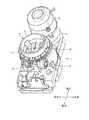
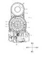
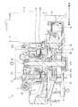
図1〜図4は、それぞれ本発明の実施の形態である抽出原料の粉砕装置を示すもので、図1は斜視図、図2は側面図、図3は平面図、図4は縦断面図である。ここで例示する抽出原料の粉砕装置は、例えばカップ式自動販売機や飲料ディスペンサ等に適用され、抽出原料であるコーヒー豆を粉砕するコーヒーミルであり、以下においては、粉砕装置をコーヒーミルとして説明する。 1 to 4 each show an apparatus for pulverizing an extraction raw material according to an embodiment of the present invention. FIG. 1 is a perspective view, FIG. 2 is a side view, FIG. 3 is a plan view, and FIG. 4 is a vertical sectional view. Is. The crushing device for the extraction raw material exemplified here is a coffee mill that is applied to, for example, a cup-type vending machine, a beverage dispenser, or the like, and crushes coffee beans that are the extraction raw material. In the following, the crushing device is described as a coffee mill. To do.
コーヒーミル1は、図には明示しない原料キャニスタから供給されたコーヒー豆を粉砕して粉原料であるコーヒー粉を生成し、図には明示しない抽出容器にコーヒー粉を供給するものであり、ケース1aを備えている。 The coffee mill 1 crushes coffee beans supplied from a raw material canister not shown in the figure to generate coffee powder as a powder raw material, and supplies the coffee powder to an extraction container not shown in the figure. 1a is provided.
ケース1aは、コーヒーミル1の外殻を構成するものであり、複数の部品を互いに組み付けることにより形成されている。このケース1aには、ミル本体部2が配設されている。 The
ミル本体部2は、上半分がケース1aの上方に突出した状態で該ケース1aに配設されている。このミル本体部2の後方には、該ミル本体部2を駆動させるためのモータ3が配設され、該ミル本体部2の前方には、該ミル本体部2から吐出されたコーヒー粉を抽出容器に供給するための粉原料供給部4が配設されている。そのようなミル本体部2は、図5にも示すように、作動時に不動となる不動ミル部10と、作動時に回転する回転ミル部20とを備えて構成されている。 The
図6は、図5に示した不動ミル部10を示す斜視図であり、図7は、図5に示した不動ミル部10を示す分解斜視図である。これら図6及び図7にも示すように、不動ミル部10は、ホッパ11と、粗粉砕リング12と、上側細粉砕リング13とを備えて構成されている。 FIG. 6 is a perspective view showing the
ホッパ11は、上下方向に延びる円筒状に形成され、上方から投入されたコーヒー豆を受け取るものである。このホッパ11は、例えばプラスチック等の樹脂の成形品から成り、その外周面には、上下方向の中央より若干上方となる位置にギア部111が設けられている。またホッパ11の外周面の下半部には雄ネジ部112が形成されており、この雄ネジ部112がねじ込まれた状態でホッパ11がケース1aに取り付けられている。よって、図1〜図4に示すように、ギア部111に噛み合うウォームギア5aを有する粒度調整ネジ5を適宜回すことにより、不動ミル部10がケース1aに対して回るように移動しながら昇降し、不動ミル部10の上側細粉砕リング13と、回転ミル部20を構成する後述する下側細粉砕リング24との隙間が調整される。これにより、上側細粉砕リング13及び下側細粉砕リング24により粉砕されるコーヒー豆の粒度を調整することができる。 The
粗粉砕リング12は、ホッパ11の内側下部にねじ止めされ、コーヒー豆を比較的粗い状態に粉砕(以下、粗粉砕ともいう)するためのものである。この粗粉砕リング12は、例えばアルミニウムやその合金等の所定の金属から成り、周壁が比較的厚い円筒状に形成されている。 The coarse crushing
この粗粉砕リング12の底部には、周方向の全体に亘って延びるとともに内方に突出する粉砕凸部121が設けられている。この粉砕凸部121は、回転ミル部20を構成する後述する原料フィーダ21と協働して、コーヒー豆を粗粉砕するものであり、該原料フィーダ21との間に、コーヒー豆の粒径よりも小さい所定の間隔を隔てた状態で突出するように構成されている。 At the bottom of the coarse crushing
また粉砕凸部121は、所定の厚みを有しており、その上面が原料フィーダ21と直交する平面に沿うように形成され、その上面に連なりかつ原料フィーダ21に対向する先端面122が、上面とで直角を為す角部を形成している。更に粉砕凸部121には、その周方向に沿って、凹状に形成された複数の凹部123が設けられている。各凹部123は、粉砕凸部121の上面と先端面122との間に亘って開放するように形成されている。 Further, the crushing
上記粗粉砕リング12の内面には、粉砕凸部121の上方に、周方向に沿って複数の凹部124が形成されている。各凹部124は、粗粉砕リング12の上面から内面に亘って開放するように形成されており、その内面が粗粉砕リング12の径方向に略沿うように形成された三角形状の三角面124aと、この三角面124aに連なり、円弧状に延びるように形成された円弧面124bとで構成されている。 On the inner surface of the coarse crushing
上側細粉砕リング13は、粗粉砕リング12の下面にねじ止めされ、下側細粉砕リング24と協働して、粗粉砕されたコーヒー豆を、より細かい状態に粉砕(以下、細粉砕ともいう)するためのものである。この上側細粉砕リング13は、例えばステンレス等の所定の金属から成り、粗粉砕リング12の粉砕凸部121の内径よりも若干大きい内径を有するとともに、粗粉砕リング12の外径よりも若干大きい外径を有している。 The upper
また上側細粉砕リング13は、内側から外側に向かって厚さが次第に大きくなるように形成されており、傾斜した下面の粉砕面13aには、各々が径方向に延びるとともに、周方向に沿って配置された多数の刃131が形成されている。 The upper
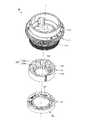
図8及び図9は、それぞれ図5に示した回転ミル部20を示す斜視図であり、図10は、図5に示した回転ミル部20を示す分解斜視図である。これら図8〜図10にも示すように、回転ミル部20は、原料フィーダ21と、ミルギア22と、原料吐出プレート(原料吐出部)23と、下側細粉砕リング(回転粉砕部)24と、通路壁リング(通路壁部)25と、案内部材26とを備えて構成されている。 8 and 9 are perspective views showing the
原料フィーダ21は、上下方向に延び、ホッパ11に投入されたコーヒー豆を下方に送出するためのものである。この原料フィーダ21は、例えばアルミニウムやその合金等の所定の金属から成り、回転部211と螺旋凸部212とを有している。 The
回転部211は、上下方向に所定長さ延びる円筒状に形成されている。螺旋凸部212は、回転部211の外周面から所定長さ突出し、回転部211の上端部から下端部に亘って時計回りの方向に一周するように螺旋状に延在している。 The
そのような原料フィーダ21は、上下方向に延びる回転軸213が回転部211に下方から挿入され、その上端から上方に突出した回転軸213に上端部に図示せぬナットが螺合して締め付けられることにより、回転軸213に固定されている。尚、回転軸213は、その下端部及び上下方向の中央よりも若干下側の位置において、ケース1aの内部に固定された軸受214によって回転自在に支持されている。 In such a
ミルギア22は、原料フィーダ21の回転軸213の下部に固定されている。このミルギア22は、比較的大きな径を有するはすば歯車で構成され、図4に示したように、回転軸213の上下の軸受214間に固定されている。またミルギア22は、モータ3の出力軸に固定された駆動ギア3aに噛み合う中間ギア3bに噛合している。 The
原料吐出プレート23は、ミルギア22の上方に固定されており、コーヒー豆の粉砕時に後述する送出通路27に送出されたコーヒー粉を収集して吐出するものである。この原料吐出プレート23は、下側細粉砕リング24の外径よりも一回り大きい径を有する円板状に形成されており、その外周部には、中心に対して周方向に沿って互いに等角度毎に配置され、上方に突出する複数の羽根部(可動部)231が設けられている。 The raw
下側細粉砕リング24は、原料吐出プレート23上にねじ止めされ、上側細粉砕リング13と協働して、粗粉砕されたコーヒー豆を、細粉砕するためのものである。この下側細粉砕リング24は、例えばステンレス等の所定の金属から成り、上側細粉砕リング13と上下対称に形成されている。また下側細粉砕リング24は、内側から外側に向かって厚さが次第に大きくなるように形成されており、傾斜した上面の粉砕面24aには、各々が径方向に延びるとともに、周方向に沿って配置された多数の刃241が形成されている。 The lower
通路壁リング25は、原料吐出プレート23の外径よりも若干大きい内径を有する円筒状に構成されている。図11に示すように、通路壁リング25には、その内外を連通する吐出口251が設けられている。このように構成された通路壁リング25は、その内周面が上側細粉砕リング13及び下側細粉砕リング24の外周面に対向し、かつその外周面全体を囲うようにケース1aに固定されている。これにより、上側細粉砕リング13及び下側細粉砕リング24の外周面と通路壁リング25の内周面との間に、上側細粉砕リング13及び下側細粉砕リング24からコーヒー粉が送出される送出通路27が画成されている。 The
そのような通路壁リング25は、帯電列上、コーヒー豆と帯電する傾向が近い材質により構成されており、具体的には、アルミニウム又はポリプロピレンにより構成されている。 Such a
案内部材26は、例えばポリアセタール等の樹脂の成形品から成り、上記吐出口251を覆う態様で通路壁リング25に取り付けられている。この案内部材26は、吐出口251から吐出されるコーヒー粉を下方に案内して上記粉原料供給部4に案内するためのものである。 The
そのような案内部材26は、抵抗片部28を有している。抵抗片部28は、例えばステンレス等の所定の金属から構成された平板状部材であり、図12に示すように、その上端部分が案内部材26の挟持部261に下方から挿入されて挟み込まれるように保持されて吐出口251を略閉塞している。つまり、抵抗片部28は、案内部材26に着脱可能に保持されており、上端部分が挟持されることにより、上下方向の中央から下方部分は、弾性変形可能である。 Such a
以上のように構成されたコーヒーミル1におけるコーヒー豆の粉砕動作について説明する。原料キャニスタから所定量のコーヒー豆がホッパ11に投入されると、コーヒーミル1は、これに前後してモータ3が駆動し、駆動ギア3a及び中間ギア3bを介してミルギア22が回転駆動する。これにより、回転ミル部20の回転軸213が上方から見て反時計回りの方向に回転し、これに伴い原料フィーダ21、原料吐出プレート23及び下側細粉砕リング24も上方から見て反時計回りの方向に回転する。 The crushing operation of coffee beans in the coffee mill 1 configured as above will be described. When a predetermined amount of coffee beans is put into the
ホッパ11のコーヒー豆は、原料フィーダ21に到達すると、この原料フィーダ21により下方に送られる。この場合、原料フィーダ21の螺旋凸部212と粗粉砕リング12の粉砕凸部121とが協働して、コーヒー豆を粗粉砕する。具体的には、原料フィーダ21の周囲のコーヒー豆は、螺旋凸部212による上方からの押圧力が作用し、そのコーヒー豆が粗粉砕リング12の粉砕凸部121の先端部に上方から押し付けられることによって剪断される。これにより、原料フィーダ21と粉砕凸部121との間を通過可能なサイズに粗粉砕されたコーヒー豆は、原料フィーダ21により、上側細粉砕リング13とのスペースを通って、上側細粉砕リング13と下側細粉砕リング24との間に送られる。 When the coffee beans in the
上述したように粗粉砕されたコーヒー豆は、回転する下側細粉砕リング24による遠心力によって、その径方向に送られながら、上側細粉砕リング13及び下側細粉砕リング24の粉砕面13a,24aによってより細かく、細粉砕される。この細粉砕によって生成されたコーヒー粉は、上側細粉砕リング13と下側細粉砕リング24との間から送出通路27に送出される。またこの場合、原料吐出プレート23の回転に伴い、複数の羽根部231が送出通路27を周回移動し、これらの羽根部231によって送出通路27のコーヒー粉が収集されながら、吐出口251から吐出される。 The coffee beans roughly crushed as described above are fed in the radial direction by the centrifugal force of the rotating lower
このように吐出口251からコーヒー粉が吐出されると、該コーヒー粉に押圧された抵抗片部28が、図12の破線で示すように吐出口251から離隔する態様で撓んで弾性変形する。これにより、コーヒー粉は、案内部材26を介して粉原料供給部4に案内された後、抽出容器に供給される。 When the coffee powder is discharged from the
以上説明したように、コーヒーミル1によれば、通路壁リング25が、帯電列上、コーヒー豆と帯電する傾向が近い材質であるアルミニウムやポリプロピレンにより構成されているので、送出通路27を通過するコーヒー粉が通路壁リング25に接しても両者の間では電荷の移動が起こりにくくなり、静電気の発生を低減させることができる。これにより、コーヒー粉が装置内部に付着して残留することを低減させ、コーヒー粉を良好に排出させることができる。しかも、静電気の発生を低減させることにより、粉原料供給部4の内壁面やその下流となる抽出容器の内壁面においてもコーヒー粉が付着して残留することを抑制でき、コーヒーミル1に供給されたコーヒー豆の量に対して抽出容器に対するコーヒー粉の供給量が低下してしまうことを抑制することができるとともに、残留するコーヒー粉により抽出容器が汚されてしまうことを抑制することができる。 As described above, according to the coffee mill 1, since the
特に、案内部材26に設けられた抵抗片部28が、常態においては吐出口251を略閉塞する一方、原料吐出プレート23によりコーヒー粉が吐出される場合には、該コーヒー粉に押圧されることにより弾性変形して吐出口251を開放するので、かかる抵抗片部28が吐出口251から吐出されるコーヒー粉の抵抗部材として作用し、送出通路27においてコーヒー粉と通路壁リング25との接触割合を増大させることができる。その結果、静電気の発生を良好に低減させることができる。 In particular, the
また抵抗片部28が案内部材26に着脱可能に設けてあるので、抵抗片部28を容易に交換可能であるとともに、専用の工具等を不要とし、抵抗片部28の取付性を向上させることができる。 Further, since the
図13は、本発明の実施の形態である抽出原料の粉砕装置の変形例を示す斜視図である。ここで例示する抽出原料の粉砕装置は、例えばカップ式自動販売機や飲料ディスペンサ等に適用され、抽出原料であるコーヒー豆を粉砕するコーヒーミル1′である。 FIG. 13 is a perspective view showing a modified example of the extraction raw material crushing apparatus according to the embodiment of the present invention. The extraction raw material pulverizing apparatus exemplified here is a coffee mill 1'which is applied to, for example, a cup type vending machine, a beverage dispenser or the like, and pulverizes coffee beans which are extraction raw materials.
かかるコーヒーミル1′では、上述したコーヒーミル1と同様に、ケース1aにミル本体部2、モータ3及び粉原料供給部4が配設されて構成されており、更にミル本体部2に対して微量(例えば1〜3グラム程度)の水を供給する水供給部(水供給手段)30が設けられている。この水供給部30は、原料キャニスタよりホッパ11に所定量のコーヒー豆が投入される直前に微量の水を供給するものである。 In the coffee mill 1 ′, like the above-described coffee mill 1, the case
このようにミル本体部2に対して水供給部30が微量の水を供給することで、回転ミル部20を構成する下側細粉砕リング24の回転によってコーヒー粉が生成される際に、水分により静電気の発生を低減させることができる。これにより、コーヒー粉が装置内部に付着して残留することを低減させ、コーヒー粉を良好に排出させることができる。 In this way, the
特に、水供給部30が、原料キャニスタよりホッパ11に所定量のコーヒー豆が投入される直前に微量の水を供給するので、コーヒー豆の粉砕時の熱等で水分を蒸発させることができ、ミル本体部2にカビ等が発生することを抑制することができる。 In particular, since the
以上、本発明の好適な実施の形態及びその変形例について説明したが、本発明はこれらに限定されるものではなく、種々の変更を行うことができる。 Although the preferred embodiment of the present invention and its modifications have been described above, the present invention is not limited to these, and various modifications can be made.
上述した実施の形態では、通路壁リング25としてアルミニウム又はポリプロピレンを例示したが、本発明においては、通路壁部の材質は、抽出原料の材質により変わるものであり、帯電列上、抽出原料と帯電する傾向が近い材質であればどのような材質であってもよい。 Although aluminum or polypropylene is illustrated as the
上述した実施の形態では、抵抗片部28が案内部材26に着脱可能に設けられていたが、本発明においては、抵抗片部は、案内部材以外に設けられていてもよい。 In the embodiment described above, the
1 コーヒーミル
1a ケース
2 ミル本体部
10 不動ミル部
11 ホッパ
12 粗粉砕リング
13 上側細粉砕リング
20 回転ミル部
21 原料フィーダ
22 ミルギア
23 原料吐出プレート
231 羽根部
24 下側細粉砕リング
25 通路壁リング
251 吐出口
26 案内部材
27 送出通路
28 抵抗片部1
Claims (4)
Translated fromJapanese前記回転粉砕部の外周面に対向しつつ該外周面全体を囲うように配設され、該外周面との間に前記粉原料が送り出される送出通路を画成する通路壁部と、
前記送出通路を移動自在の可動部を有し、該可動部が該送出通路を移動することにより該送出通路に送り出された粉原料を収集し、かつ前記通路壁部に形成された吐出口から粉原料を吐出する原料吐出部と
を備えた抽出原料の粉砕装置であって、
前記通路壁部は、帯電列上、前記抽出原料と帯電する傾向が近い材質により構成されるもので、
前記吐出口から吐出された前記粉原料を下方に案内する案内部材と、
常態においては前記吐出口を略閉塞する一方、前記原料吐出部により前記粉原料が吐出される場合には、該粉原料に押圧されることにより弾性変形して前記吐出口を開放する抵抗片部と
を備え、
前記抵抗片部は、上端部分が前記案内部材の挟持部に挿入されて着脱可能に挟持された金属製のものであることを特徴とする抽出原料の粉砕装置。A rotary crushing unit configured to be rotatable about its own central axis, crushing the supplied extraction raw material while rotating, and sending out a powdered raw material that is the pulverized extraction raw material in the radial direction of the central axis,
A passage wall portion that is arranged so as to surround the entire outer peripheral surface while facing the outer peripheral surface of the rotary crushing unit, and that defines a delivery passage for sending out the powder raw material between the outer peripheral surface and the outer peripheral surface,
The delivery passage has a movable portion that is movable, and the movable portion moves in the delivery passage to collect the powder raw material delivered to the delivery passage, and from a discharge port formed in the passage wall portion. A raw material discharge unit for discharging a powder raw material, comprising:
Said passageway wall, the triboelectric series,in shall be constituted of a material tendency closer to charging to the extraction rawmaterial,
A guide member for guiding the powder raw material discharged from the discharge port downward,
In the normal state, while the discharge port is substantially closed, when the powder material is discharged by the raw material discharge part, the resistance piece part that is elastically deformed by being pressed by the powder raw material and opens the discharge port When
Equipped with
The said resistance piece part is a metal thing which the upper end part was inserted in the holding part of the said guide member, and was hold | maintained detachably , The crushing apparatus of the extraction raw material characterizedby the above-mentioned .
前記回転粉砕部の外周面に対向しつつ該外周面全体を囲うように配設され、該外周面との間に前記粉原料が送り出される送出通路を画成する通路壁部と、
前記送出通路を移動自在の可動部を有し、該可動部が該送出通路を移動することにより該送出通路に送り出された粉原料を収集し、かつ前記通路壁部に形成された吐出口から粉原料を吐出する原料吐出部と
を備えた抽出原料の粉砕装置であって、
前記回転粉砕部に対して微量の水を供給する水供給手段を備えたことを特徴とする抽出原料の粉砕装置。A rotary crushing unit configured to be rotatable about its own central axis, crushing the supplied extraction raw material while rotating, and sending out a powdered raw material that is the pulverized extraction raw material in the radial direction of the central axis,
A passage wall portion that is arranged so as to surround the entire outer peripheral surface while facing the outer peripheral surface of the rotary crushing unit, and that defines a delivery passage for sending out the powder raw material between the outer peripheral surface and the outer peripheral surface,
The delivery passage has a movable portion that is movable, and the movable portion moves in the delivery passage to collect the powder raw material delivered to the delivery passage, and from a discharge port formed in the passage wall portion. A raw material discharge unit for discharging a powder raw material, comprising:
A pulverizing apparatus for extracting raw material, comprising water supply means for supplying a small amount of water to the rotary pulverizing section.
Priority Applications (4)
| Application Number | Priority Date | Filing Date | Title |
|---|---|---|---|
| JP2018103641AJP6690668B2 (en) | 2018-05-30 | 2018-05-30 | Extraction raw material crusher |
| PCT/JP2019/018400WO2019230314A1 (en) | 2018-05-30 | 2019-05-08 | Device for crushing extraction raw material |
| KR1020207030655AKR102445076B1 (en) | 2018-05-30 | 2019-05-08 | Crushing device for extraction raw materials |
| CN201980029532.9ACN112055552B (en) | 2018-05-30 | 2019-05-08 | Crushing device for extracting raw materials |
Applications Claiming Priority (1)
| Application Number | Priority Date | Filing Date | Title |
|---|---|---|---|
| JP2018103641AJP6690668B2 (en) | 2018-05-30 | 2018-05-30 | Extraction raw material crusher |
Publications (2)
| Publication Number | Publication Date |
|---|---|
| JP2019205783A JP2019205783A (en) | 2019-12-05 |
| JP6690668B2true JP6690668B2 (en) | 2020-04-28 |
Family
ID=68697341
Family Applications (1)
| Application Number | Title | Priority Date | Filing Date |
|---|---|---|---|
| JP2018103641AActiveJP6690668B2 (en) | 2018-05-30 | 2018-05-30 | Extraction raw material crusher |
Country Status (4)
| Country | Link |
|---|---|
| JP (1) | JP6690668B2 (en) |
| KR (1) | KR102445076B1 (en) |
| CN (1) | CN112055552B (en) |
| WO (1) | WO2019230314A1 (en) |
Families Citing this family (5)
| Publication number | Priority date | Publication date | Assignee | Title |
|---|---|---|---|---|
| IT201900013392A1 (en)* | 2019-07-31 | 2021-01-31 | Gruppo Cimbali Spa | Antistatic grinder device for roasted coffee beans intended for the formation of a beverage |
| US20240407603A1 (en)* | 2021-09-23 | 2024-12-12 | Whirlpool Corporation | Coffee grinder |
| CA3194245A1 (en)* | 2021-12-03 | 2023-06-03 | Daito Giken, Inc. | Coffee machine |
| CN114271682A (en)* | 2022-01-28 | 2022-04-05 | 中山市思雅电器科技有限公司 | Automatic drying and bean grinding coffee machine |
| JP7684666B1 (en) | 2023-12-27 | 2025-05-28 | Hario株式会社 | Coffee mill |
Family Cites Families (13)
| Publication number | Priority date | Publication date | Assignee | Title |
|---|---|---|---|---|
| JPS55138422A (en)* | 1979-04-18 | 1980-10-29 | Matsushita Electric Industrial Co Ltd | Coffee maker |
| JP3178194B2 (en) | 1993-11-05 | 2001-06-18 | 富士電機株式会社 | Coffee mill |
| US5950941A (en)* | 1998-05-04 | 1999-09-14 | Grindmaster Corporation | Dissipator for reducing electrostatic charge in fines generated by a coffee grinder |
| JP3583312B2 (en)* | 1999-05-28 | 2004-11-04 | 株式会社 伊藤園 | Method and apparatus for producing coffee beverage |
| JP2001297373A (en)* | 2000-04-13 | 2001-10-26 | Matsushita Refrig Co Ltd | Coffee mill for automatic vending machine |
| AU2009292722B8 (en)* | 2008-09-17 | 2017-01-19 | Koninklijke Douwe Egberts B.V. | System and method for preparing coffee beverage |
| JP6019546B2 (en)* | 2011-07-11 | 2016-11-02 | 凸版印刷株式会社 | Measuring spoon |
| JP5849519B2 (en)* | 2011-08-12 | 2016-01-27 | 富士電機株式会社 | Beverage extraction material crusher |
| CN102309256B (en)* | 2011-09-19 | 2013-10-09 | 美的集团股份有限公司 | Coffee bean grinder and coffeemaker with same |
| CN202515436U (en)* | 2011-11-30 | 2012-11-07 | 伟嘉电业有限公司 | coffee bean grinder |
| CN203263138U (en)* | 2013-05-24 | 2013-11-06 | 快达实业有限公司 | coffee grinder |
| WO2015077237A2 (en)* | 2013-11-20 | 2015-05-28 | Starbucks Corporation D/B/A Starbucks Coffee Company | Cooking system power management |
| JP6791685B2 (en)* | 2016-09-01 | 2020-11-25 | ツインバード工業株式会社 | coffee maker |
- 2018
- 2018-05-30JPJP2018103641Apatent/JP6690668B2/enactiveActive
- 2019
- 2019-05-08WOPCT/JP2019/018400patent/WO2019230314A1/ennot_activeCeased
- 2019-05-08KRKR1020207030655Apatent/KR102445076B1/enactiveActive
- 2019-05-08CNCN201980029532.9Apatent/CN112055552B/enactiveActive
Also Published As
| Publication number | Publication date |
|---|---|
| CN112055552A (en) | 2020-12-08 |
| JP2019205783A (en) | 2019-12-05 |
| WO2019230314A1 (en) | 2019-12-05 |
| CN112055552B (en) | 2022-08-23 |
| KR20200133384A (en) | 2020-11-27 |
| KR102445076B1 (en) | 2022-09-19 |
Similar Documents
| Publication | Publication Date | Title |
|---|---|---|
| JP6690668B2 (en) | Extraction raw material crusher | |
| JP5849519B2 (en) | Beverage extraction material crusher | |
| JP6871582B2 (en) | Coffee bean crushing mechanism | |
| JP6033364B1 (en) | Coffee grinder | |
| JP2018069136A (en) | Electric milling machine | |
| JP2015039555A (en) | Mill device | |
| JP5765113B2 (en) | Beverage extraction material crusher | |
| JP5577918B2 (en) | Beverage powder raw material metering device | |
| CN118284355A (en) | Coffee grinder | |
| JP3945957B2 (en) | Coffee mill equipment | |
| KR20150143111A (en) | Crusher | |
| JP6358898B2 (en) | Beverage production equipment | |
| JP2016015998A (en) | Coffee bean pulverization device | |
| JP2017018869A (en) | Crushing classifier | |
| JP2001224979A (en) | Pulverizing machine | |
| JP5469981B2 (en) | Powder raw material supply equipment | |
| CN208436969U (en) | Newtype drug pulverizer | |
| JP4080118B2 (en) | Tea leaf grinder | |
| KR20190030353A (en) | Eco-friendly food crusher | |
| US360284A (en) | Feeder for grinding-mills | |
| US559980A (en) | Rock crushing and grinding apparatus | |
| JP2002331251A (en) | Disposer | |
| JP2024036195A (en) | Grinding device | |
| JPS63286114A (en) | Grinder of coffee beans | |
| US457146A (en) | Ments |
Legal Events
| Date | Code | Title | Description |
|---|---|---|---|
| A621 | Written request for application examination | Free format text:JAPANESE INTERMEDIATE CODE: A621 Effective date:20191011 | |
| A131 | Notification of reasons for refusal | Free format text:JAPANESE INTERMEDIATE CODE: A131 Effective date:20191119 | |
| A521 | Request for written amendment filed | Free format text:JAPANESE INTERMEDIATE CODE: A523 Effective date:20200120 | |
| TRDD | Decision of grant or rejection written | ||
| A01 | Written decision to grant a patent or to grant a registration (utility model) | Free format text:JAPANESE INTERMEDIATE CODE: A01 Effective date:20200310 | |
| A61 | First payment of annual fees (during grant procedure) | Free format text:JAPANESE INTERMEDIATE CODE: A61 Effective date:20200323 | |
| R150 | Certificate of patent or registration of utility model | Ref document number:6690668 Country of ref document:JP Free format text:JAPANESE INTERMEDIATE CODE: R150 | |
| R250 | Receipt of annual fees | Free format text:JAPANESE INTERMEDIATE CODE: R250 | |
| R250 | Receipt of annual fees | Free format text:JAPANESE INTERMEDIATE CODE: R250 | |
| R250 | Receipt of annual fees | Free format text:JAPANESE INTERMEDIATE CODE: R250 |