JP6689850B2 - Graphic user interface of biopsy device - Google Patents
Graphic user interface of biopsy deviceDownload PDFInfo
- Publication number
- JP6689850B2 JP6689850B2JP2017528162AJP2017528162AJP6689850B2JP 6689850 B2JP6689850 B2JP 6689850B2JP 2017528162 AJP2017528162 AJP 2017528162AJP 2017528162 AJP2017528162 AJP 2017528162AJP 6689850 B2JP6689850 B2JP 6689850B2
- Authority
- JP
- Japan
- Prior art keywords
- tissue sample
- tissue
- probe
- sample holder
- button
- Prior art date
- Legal status (The legal status is an assumption and is not a legal conclusion. Google has not performed a legal analysis and makes no representation as to the accuracy of the status listed.)
- Active
Links
- 238000001574biopsyMethods0.000titleclaimsdescription290
- 239000000523sampleSubstances0.000claimsdescription608
- FAPWRFPIFSIZLT-UHFFFAOYSA-MSodium chlorideChemical compound[Na+].[Cl-]FAPWRFPIFSIZLT-UHFFFAOYSA-M0.000claimsdescription27
- 239000011780sodium chlorideSubstances0.000claimsdescription25
- 238000004891communicationMethods0.000claimsdescription21
- 238000005070samplingMethods0.000claimsdescription18
- 210000001519tissueAnatomy0.000description454
- 238000000034methodMethods0.000description55
- 239000003550markerSubstances0.000description30
- 239000012530fluidSubstances0.000description26
- 238000010304firingMethods0.000description16
- 230000006870functionEffects0.000description14
- 238000007789sealingMethods0.000description12
- 230000008878couplingEffects0.000description11
- 238000010168coupling processMethods0.000description11
- 238000005859coupling reactionMethods0.000description11
- 239000000463materialSubstances0.000description11
- 238000003825pressingMethods0.000description10
- 230000007704transitionEffects0.000description9
- 210000000481breastAnatomy0.000description8
- 238000010079rubber tappingMethods0.000description8
- 238000005520cutting processMethods0.000description6
- 238000005516engineering processMethods0.000description6
- 230000007246mechanismEffects0.000description6
- 230000005855radiationEffects0.000description6
- 238000012546transferMethods0.000description6
- 238000013459approachMethods0.000description5
- 230000008569processEffects0.000description5
- 230000004044responseEffects0.000description5
- 238000001356surgical procedureMethods0.000description5
- 210000001124body fluidAnatomy0.000description4
- 238000004140cleaningMethods0.000description4
- 239000008280bloodSubstances0.000description3
- 210000004369bloodAnatomy0.000description3
- 239000003086colorantSubstances0.000description3
- 238000003780insertionMethods0.000description3
- 230000037431insertionEffects0.000description3
- 210000004872soft tissueAnatomy0.000description3
- 241000894006BacteriaSpecies0.000description2
- IAYPIBMASNFSPL-UHFFFAOYSA-NEthylene oxideChemical compoundC1CO1IAYPIBMASNFSPL-UHFFFAOYSA-N0.000description2
- 239000004775TyvekSubstances0.000description2
- 229920000690TyvekPolymers0.000description2
- 230000009471actionEffects0.000description2
- 210000000577adipose tissueAnatomy0.000description2
- 230000015572biosynthetic processEffects0.000description2
- 239000010839body fluidSubstances0.000description2
- 230000008859changeEffects0.000description2
- 238000012790confirmationMethods0.000description2
- 238000010276constructionMethods0.000description2
- 229940079593drugDrugs0.000description2
- 239000003814drugSubstances0.000description2
- 238000012377drug deliveryMethods0.000description2
- 238000005286illuminationMethods0.000description2
- 238000011503in vivo imagingMethods0.000description2
- 238000007689inspectionMethods0.000description2
- 230000013011matingEffects0.000description2
- 230000008520organizationEffects0.000description2
- 230000000149penetrating effectEffects0.000description2
- 230000001954sterilising effectEffects0.000description2
- 238000004659sterilization and disinfectionMethods0.000description2
- 238000003860storageMethods0.000description2
- 238000002604ultrasonographyMethods0.000description2
- 230000000007visual effectEffects0.000description2
- 206010053567CoagulopathiesDiseases0.000description1
- 206010018852HaematomaDiseases0.000description1
- 230000005355Hall effectEffects0.000description1
- 208000032843HemorrhageDiseases0.000description1
- 230000004913activationEffects0.000description1
- 230000006978adaptationEffects0.000description1
- 210000003484anatomyAnatomy0.000description1
- 230000000712assemblyEffects0.000description1
- 238000000429assemblyMethods0.000description1
- 230000008901benefitEffects0.000description1
- 239000012472biological sampleSubstances0.000description1
- 230000000740bleeding effectEffects0.000description1
- 230000035602clottingEffects0.000description1
- 230000000295complement effectEffects0.000description1
- 230000008602contractionEffects0.000description1
- 238000010586diagramMethods0.000description1
- 230000002452interceptive effectEffects0.000description1
- 229940127554medical productDrugs0.000description1
- 239000002184metalSubstances0.000description1
- 238000012986modificationMethods0.000description1
- 230000004048modificationEffects0.000description1
- 230000007170pathologyEffects0.000description1
- 238000002360preparation methodMethods0.000description1
- 210000002307prostateAnatomy0.000description1
- 239000007787solidSubstances0.000description1
- 238000007920subcutaneous administrationMethods0.000description1
- 210000001685thyroid glandAnatomy0.000description1
- 238000013519translationMethods0.000description1
- 238000012800visualizationMethods0.000description1
Images


Classifications
- A—HUMAN NECESSITIES
- A61—MEDICAL OR VETERINARY SCIENCE; HYGIENE
- A61B—DIAGNOSIS; SURGERY; IDENTIFICATION
- A61B10/00—Instruments for taking body samples for diagnostic purposes; Other methods or instruments for diagnosis, e.g. for vaccination diagnosis, sex determination or ovulation-period determination; Throat striking implements
- A61B10/02—Instruments for taking cell samples or for biopsy
- A61B10/0233—Pointed or sharp biopsy instruments
- A61B10/0266—Pointed or sharp biopsy instruments means for severing sample
- A61B10/0275—Pointed or sharp biopsy instruments means for severing sample with sample notch, e.g. on the side of inner stylet
- A—HUMAN NECESSITIES
- A61—MEDICAL OR VETERINARY SCIENCE; HYGIENE
- A61B—DIAGNOSIS; SURGERY; IDENTIFICATION
- A61B34/00—Computer-aided surgery; Manipulators or robots specially adapted for use in surgery
- A61B34/25—User interfaces for surgical systems
- A—HUMAN NECESSITIES
- A61—MEDICAL OR VETERINARY SCIENCE; HYGIENE
- A61B—DIAGNOSIS; SURGERY; IDENTIFICATION
- A61B10/00—Instruments for taking body samples for diagnostic purposes; Other methods or instruments for diagnosis, e.g. for vaccination diagnosis, sex determination or ovulation-period determination; Throat striking implements
- A61B10/0096—Casings for storing test samples
- A—HUMAN NECESSITIES
- A61—MEDICAL OR VETERINARY SCIENCE; HYGIENE
- A61B—DIAGNOSIS; SURGERY; IDENTIFICATION
- A61B10/00—Instruments for taking body samples for diagnostic purposes; Other methods or instruments for diagnosis, e.g. for vaccination diagnosis, sex determination or ovulation-period determination; Throat striking implements
- A61B10/02—Instruments for taking cell samples or for biopsy
- A61B2010/0225—Instruments for taking cell samples or for biopsy for taking multiple samples
- A—HUMAN NECESSITIES
- A61—MEDICAL OR VETERINARY SCIENCE; HYGIENE
- A61B—DIAGNOSIS; SURGERY; IDENTIFICATION
- A61B17/00—Surgical instruments, devices or methods
- A61B2017/00017—Electrical control of surgical instruments
- A61B2017/00199—Electrical control of surgical instruments with a console, e.g. a control panel with a display
Landscapes
- Health & Medical Sciences (AREA)
- Life Sciences & Earth Sciences (AREA)
- Engineering & Computer Science (AREA)
- Surgery (AREA)
- General Health & Medical Sciences (AREA)
- Animal Behavior & Ethology (AREA)
- Veterinary Medicine (AREA)
- Biomedical Technology (AREA)
- Heart & Thoracic Surgery (AREA)
- Medical Informatics (AREA)
- Molecular Biology (AREA)
- Public Health (AREA)
- Pathology (AREA)
- Human Computer Interaction (AREA)
- Robotics (AREA)
- Nuclear Medicine, Radiotherapy & Molecular Imaging (AREA)
- Surgical Instruments (AREA)
- Sampling And Sample Adjustment (AREA)
Description
Translated fromJapanese本発明は、生検装置のグラフィックユーザインタフェースに関する。 The present invention relates to a graphic user interface for a biopsy device.
生検サンプルは、多様な装置を使用して多様な医療施術で多様な方法で得られた。生検装置は、定位誘導、超音波誘導、MRI誘導、PEM誘導、BSGI誘導、又は他の方法で使用されることができる。例えば、一部の生検装置は、患者から1つ以上の生検サンプルを採取するために、片手を使用して一回の挿入でユーザが完全に操作することができる。また、一部の生検装置は、例えば、流体の伝達(例えば、加圧空気、食塩水、大気、真空等)、電力の伝達、及び/又は命令の伝達などのような真空モジュール及び/又は制御モジュールに接続されることができる。その他の生検装置は、テザリング(tethered)、又は他の装置と接続されることなく、完全に又は少なくとも部分的に作動可能であり得る。 Biopsy samples were obtained in a variety of ways with a variety of medical procedures using a variety of devices. The biopsy device can be used with stereotactic guidance, ultrasound guidance, MRI guidance, PEM guidance, BSGI guidance, or other methods. For example, some biopsy devices can be fully manipulated by a user with one insertion using one hand to obtain one or more biopsy samples from a patient. Also, some biopsy devices may include vacuum modules and / or, for example, fluid transfer (eg, pressurized air, saline, atmosphere, vacuum, etc.), power transfer, and / or command transfer, etc. It can be connected to the control module. Other biopsy devices may be fully or at least partially operable without tethered or interfacing with other devices.
単なる例示的な生検装置及び生検システム構成要素が1996年6月18日に発行された「自動化された生検及び軟組織採取方法及び装置」という名称の米国特許第5,526,822号;1999年7月27日に発行された「自動化された生検及び軟組織採取装置」という名称の米国特許第5,928,164号;2000年1月25日に発行された米国特許第6,017,316号「自動化された生検装置用真空制御システム及び方法」;2000年7月11日に発行された米国特許第6,086,544号「自動化された手術生検装置のための制御装置」;2000年12月19日に発行された米国特許第6,162,187号「外科用流体収集装置」;2002年8月13日に発行された「作動モードを選択するための遠隔制御を有する外科用生検システムを使用する方法」という名称の米国特許第6,432,065号;2003年9月11日に発行された米国特許第6,626,849号「MRI互換外科的生検装置」;2004年6月22日に発行された米国特許第6,752,768号「手術モードを選択するための遠隔制御を有する手術生検システム」;2008年10月8日に発行された米国特許第7,442,171号「外科的生検装置用遠隔サムホイール」;2010年1月19日に発行された「手動回転可能ピアッサー(Manual Rotatable Piercer)」という名称の米国特許第7,648,466号;2010年11月23日に発行された「生検装置組織ポート調整(Biopsy Device Tissue Port Adjustment)」という名称の米国特許第7,837,632号;2010年12月1日に発行された「テザーレス生検装置のためのクラッチ及びバルブシステム」という名称の米国特許第7,854,706号;2011年3月29日に発行された米国特許第7,914,464号の「手術モードを選択するための遠隔制御を有する手術生検システム」;2011年5月10日に発行された「生検装置のための真空タイミングアルゴリズム」という名称の米国特許第7,938,786号;2011年12月21日に発行された「回転可能にリンクされたサムホイール及び組織サンプルホルダを有する組織生検装置」という名称の米国特許第8,083,687号;及び2012年2月21日に発行された米国特許第8,118,755号、「生検サンプル保管」に開示されている。上記引用された米国特許の各々の開示は本願に参照として含まれる。 No. 5,526,822 entitled "Automated Biopsy and Soft Tissue Collection Methods and Devices," issued June 18, 1996, merely exemplary biopsy devices and biopsy system components; US Pat. No. 5,928,164 entitled “Automated Biopsy and Soft Tissue Harvester” issued July 27, 1999; US Pat. No. 6,017 issued January 25, 2000. , 316, "Vacuum control system and method for automated biopsy device"; U.S. Pat. No. 6,086,544, issued July 11, 2000, "Controller for automated surgical biopsy device." U.S. Pat. No. 6,162,187 issued Dec. 19, 2000 "Surgical fluid collector"; issued Aug. 13, 2002 "Remote control for selecting mode of operation." Existence US Pat. No. 6,432,065 entitled “Method of Using a Surgical Biopsy System”; US Pat. No. 6,626,849 “MRI Compatible Surgical Biopsy” issued Sep. 11, 2003. Device "; U.S. Patent No. 6,752,768, issued June 22, 2004" Surgical biopsy system with remote control for selecting surgical mode "; Issued October 8, 2008 U.S. Pat. No. 7,442,171, "Remote Thumbwheel for Surgical Biopsy Devices"; U.S. Pat. No. 7, entitled "Manually Rotatable Piercer", issued January 19, 2010. 648,466; "Biopsy Device Tissue Port Ad," issued November 23, 2010. US Pat. No. 7,837,632; US Pat. No. 7,854,706, entitled “Clutch and Valve System for Tetherless Biopsy Devices,” issued Dec. 1, 2010. No .; US Pat. No. 7,914,464, issued Mar. 29, 2011, "Surgical biopsy system with remote control for selecting surgical mode", issued May 10, 2011. U.S. Pat. No. 7,938,786 entitled "Vacuum Timing Algorithm for Biopsy Devices"; "Tissue with rotatably linked thumbwheel and tissue sample holder," issued December 21, 2011. U.S. Pat. No. 8,083,687 entitled "Biopsy Device"; and U.S. Pat. No. 8,118,755 issued Feb. 21, 2012. No., "Biopsy sample storage". The disclosure of each of the above cited US patents is incorporated herein by reference.
付加的な例示的な生検装置及び生検システム構成要素は、2006年4月6日に公開された「生検装置及び方法」という名称の米国出願公開番号第2006/0074345号;2008年6月19日に公開された「真空制御モジュールを有する生検システム」という名称の米国出願公開番号第2008/0146962号;2008年9月4日に公開された「生検装置による生体サンプル提示」という名称の米国出願公開番号第2008/0214955号;2008年9月11日に公開された「生検サンプル保管」という名称の米国出願公開番号第2008/0221480号;2009年5月21日に公開された「生検システム制御モジュール用グラフィックユーザインタフェース」という名称の米国出願公開番号第2009/0131821号;2009年5月21日に公開された「生体システム制御モジュール上のアイコンに基づくユーザインタフェース」という名称の米国出願公開番号第2009/0131820号;2009年8月27日に公開された「生検装置用針チップ」という名称の米国出願公開番号第2009/0216152号;2010年5月6日に公開された「回転可能な組織サンプルホルダを有する生検装置」という名称の米国出願公開番号第2010/0113973号;2010年6月17日に公開された「ピストルグリップ(Pistol Grip)を用いた手作動式テザーレス生検装置」という名称の米国出願公開番号第2010/0152610号;2010年6月24日に公開された「中央サムホイールを含む生検装置」という名称の米国出願公開番号第2010/0160819号;2010年6月24日に公開された「離散組織チャンバを有する生検装置」という名称の米国出願公開番号第2010/0160824号;2010年12月16日に公開された「再使用可能な部分を有するテザーレス(Tetherless)生検装置」という名称の米国出願公開番号第2010/0317997号;2012年5月3日に公開された「針発射(Needle Firing)を備えたハンドヘルド生検装置」という名称の米国出願公開番号第2012/0109007号;2012年10月18日に公開された「電動式針発射生検装置」という名称の米国出願公開番号第2012/0265095号;2012年11月8日に公開された「多岐管整列機能及び組織センサを有する生検装置」という名称の米国出願公開番号第2012/0283563号;2012年12月6日に公開された「生検装置用針組立体及びブレード組立体」という名称の米国出願公開番号第2012/0310110号;2013年2月14日に公開された「生検装置のためのアクセスチャンバ及びマーカー」という名称の米国出願公開番号第2013/0041256号;2013年2月28日に公開された「バルクチャンバ及び病理学チャンバを有する生検装置組織サンプルホルダ」という名称の米国出願公開番号第2013/0053724号;2013年6月13日に公開された「スライド−インプローブを有する生検装置」という名称の米国出願公開番号第2013/0150751号;2013年12月5日に公開された「生検装置制御」という名称の米国出願公開番号第2013/0324882号;2013年8月22日に公開された「生検装置バルブアセンブリ」という名称の米国出願公開番号第2013/0218047号;及び2014年2月6日に公開された「生検システム」という名称の米国出願公開番号第2014/0039343号に開示されている。前記米国特許出願公報の各々の開示は本願に参照として引用されている。 Additional exemplary biopsy devices and biopsy system components are described in US Application Publication No. 2006/0074345, entitled "Biopsy Devices and Methods," published April 6, 2006; U.S. Application Publication No. 2008/0146962 entitled "Biopsy System with Vacuum Control Module", published 19th May; "Presentation of biological sample by biopsy device", published 4th September 2008 US Application Publication No. 2008/0214955 entitled; US Application Publication No. 2008/0221480 entitled "Biopsy Sample Storage" published September 11, 2008; published May 21, 2009 US Application Publication No. 2009/013 entitled "Graphic User Interface for Biopsy System Control Modules" No. 821; published on May 21, 2009; US Application Publication No. 2009/0131820 entitled "User Interface Based on Icon on Biological System Control Module"; Published on August 27, 2009; US Application Publication No. 2009/0216152 entitled "Biopsy Device Needle Tip"; US Application Publication Number entitled "Biopsy Device with Rotatable Tissue Sample Holder" published May 6, 2010 No. 2010/0113973; US Application Publication No. 2010/0152610; June 2010, entitled "Hand Operated Tetherless Biopsy Device Using Pistol Grip," Published June 17, 2010. Of the name "Biopsy device including the central thumbwheel" released on the 24th of March U.S. Application Publication No. 2010/0160819; published on June 24, 2010 entitled "Biopsy Device with Discrete Tissue Chamber" U.S. Application Publication No. 2010/0160824; Dec. 16, 2010. Published U.S. Application Publication No. 2010/0317997 entitled "Tetherless Biopsy Device with Reusable Part"; published "Needle Firing" published May 3, 2012. U.S. Application Publication No. 2012/0109007 entitled "Handheld Biopsy Device Equipped"; No .; “Manifold Alignment Function and Organization Center” published on November 8, 2012. United States Application Publication No. 2012/0283563 entitled "Biopsy Device with a Biopsy Device; United States Application Publication Number No." Needle Assembly and Blade Assembly for a Biopsy Device "published December 6, 2012. 2012/0310110; published on February 14, 2013, US Application Publication No. 2013/0041256 entitled "Access Chambers and Markers for Biopsy Devices"; Published February 28, 2013 U.S. Application Publication No. 2013/0053724 entitled "Biopsy Device Tissue Sample Holder with Bulk Chamber and Pathology Chamber"; "Biopsy Device with Slide-In Probe" published June 13, 2013. US Application Publication No. 2013/0150751 entitled; Published December 5, 2013 U.S. Application Publication No. 2013/0324882 entitled "Biopsy Device Control"; US Application Publication No. 2013/0218047 entitled "Biopsy Device Valve Assembly" published August 22, 2013; And U.S. Application Publication No. 2014/0039343, entitled "Biopsy System," published February 6, 2014. The disclosure of each of the foregoing US patent application publications is incorporated herein by reference.
一部の環境では後に参照できるように生検部位の位置を表示することが好ましい場合がある。例えば、組織サンプルが生検部位から採られる前、途中又は後に1つ以上のマーカーが生検サイトに沈殿され得る。代表的なマーカー配置道具は、米国オハイオ州シンシナティ市にあるDevicor Medical Products,Inc.のMAMMOMARK(商標)、MICROMARK(登録商標)及びCORMARK(商標)ブランドデバイスを含む。生検サイトをマーキングするための他の例示的な装置及び方法は、2009年8月20日に公開された「生検方法」という名称の米国出願公開番号第2009/0209854号;2009年10月29日に公開された「映像に有用な装置」という名称の米国出願公開番号第2009/0270725号;2010年2月25日に公開された「生検マーカー伝達装置」という名称の米国出願公開番号第2010/0049084号;2011年3月24日に公開された「フレキシブル生検マーカー伝達装置」という名称の米国出願公開番号第2011/0071423号;2011年3月24日に公開された「生検マーカー伝達装置」という名称の米国出願公開番号第2011/0071424号;2011年3月24日に公開された「位置決定構成要素を有する生検マーカー伝達装置」という名称の米国出願公開番号第2011/0071391号;2001年5月8日に発行された米国特許第6,228,055号「身体組織の特定位置を表示して定義するための装置」;2002年4月16日に発行された「皮下共同マーキング装置及び方法」という名称の米国特許第6,371,904号;2006年1月31日に発行された「生体内のイメージングのための組織サイトマーカー」という名称の米国特許第6,993,375号;2006年2月7日に発行された「映像化可能な生検サイトマーカー(Imageable Biopsy Site Marker)」という名称の米国特許第6,996,433号;2006年5月16日に発行された米国特許第7,044,957号「組織を定義して表示する装置」;2006年5月16日に発行された「生体内のイメージングのための組織サイトマーカー」という名称の米国特許第7,047,063号;2007年6月12日に発行された米国特許第7,229,417号「生検部位のマーキング方法」;及び2008年12月16日に発行された米国特許第7,465,279号「マーカー装置及び外科的生検装置を用いた共同マーカー配置方法」に開示されている。上記引用された米国特許及び米国公開特許の各々の開示は本願に参照として含まれる。 In some circumstances it may be preferable to display the location of the biopsy site for later reference. For example, one or more markers may be deposited at the biopsy site before, during or after the tissue sample is taken from the biopsy site. A typical marker placement tool is Device Medical Products, Inc., located in Cincinnati, Ohio, USA. Includes MAMMOMARK ™, MICROMMARK ™ and CORMARK ™ brand devices. Other exemplary devices and methods for marking biopsy sites are described in US Application Publication No. 2009/0209854, entitled "Biopsy Method," published August 20, 2009; October 2009. U.S. Application Publication No. 2009/0270725 entitled "Devices Useful for Video", published 29th; U.S. Application Publication Number, entitled "Biopsy Marker Transmitter," published 25 Feb 2010 No. 2010/0049084; US Application Publication No. 2011/0071423 entitled "Flexible Biopsy Marker Transmitter" published March 24, 2011; "Biopsy published March 24, 2011. US Application Publication No. 2011/0071424 entitled "Marker Transmitter"; "Position" published March 24, 2011 U.S. Application Publication No. 2011/0071391 entitled "Biopsy Marker Transmitter with Constant Components"; U.S. Pat. No. 6,228,055 issued May 8, 2001, "Determining specific locations of body tissue. Device for Displaying and Defining "; US Pat. No. 6,371,904 entitled" Subcutaneous Joint Marking Device and Method, "issued Apr. 16, 2002; issued Jan. 31, 2006 U.S. Patent No. 6,993,375 entitled "Tissue Site Marker for In Vivo Imaging"; "Imageable Biopsy Site Marker," issued Feb. 7, 2006. ) ”US Pat. No. 6,996,433; US Pat. No. 7,044 issued May 16, 2006. 957, "Device for defining and displaying tissue"; US Pat. No. 7,047,063, entitled "Tissue site marker for in vivo imaging", issued May 16, 2006; 2007. U.S. Patent No. 7,229,417, "Method for marking biopsy sites," issued June 12, and U.S. Patent No. 7,465,279, "Marker Device and, issued December 16, 2008." Collaborative marker placement method using a surgical biopsy device ". The disclosures of each of the above cited US patents and US published patents are incorporated herein by reference.
生検サンプルを得るために様々なシステム及び方法が作られて用いられたが、 本発明者以前の何者も添付された請求範囲に説明された発明を作る又は使用したことはないと信じられる。 While various systems and methods have been made and used to obtain biopsy samples, it is believed that no one before the inventor has made or used the invention described in the appended claims.
プローブセット、ホルスタ及びユーザインタフェースを含む生検システムが提供される。プローブセットは複数のプローブを含む。プローブセットの各プローブは、プローブ本体、針、カッタ及び組織サンプルホルダを含む。組織サンプルホルダはカッタと連結され1つ以上の組織サンプルを収容する。ホルスタはプローブセットの各プローブに選択的に固定できる。ユーザインタフェースはホルスタと通信する。ユーザインタフェースはディスプレイを含む。ユーザインタフェースはプローブセットの選択されたプローブがホルスタに固定される時、プローブセットのどのプローブがホルスタに固定されるかを識別するように構成される。 A biopsy system is provided that includes a probe set, a holster and a user interface. The probe set includes a plurality of probes. Each probe of the probe set includes a probe body, a needle, a cutter and a tissue sample holder. The tissue sample holder is coupled to the cutter and contains one or more tissue samples. The holster can be selectively affixed to each probe in the probe set. The user interface is in communication with the holster. The user interface includes a display. The user interface is configured to identify which probe of the probe set is fixed to the holster when the selected probe of the probe set is fixed to the holster.
本発明の実施形態は、従来の内視鏡及び開放手術器具だけでなくロボット補助手術での適用を有する。 Embodiments of the present invention have application in robotic assisted surgery as well as conventional endoscopes and open surgical instruments.
単なる例として、ここに記述された実施形態は手術前に処理されることができる。まず、新しい装備又は中古装備を手に入れて必要な場合は治療できる。その後、装備を滅菌できる。1つの殺菌技術で、機器はプラスチック又はTYVEKバックのような密閉かつ封止された容器に置かれる。その後、コンテナと道具はガンマ線、X線又は高エネルギー電子のように容器を貫通できる放射線分野に配置されることができる。放射線は装備と容器のバクテリアを殺すことができる。その後、殺菌された器具は殺菌された容器に貯蔵されることができる。密閉された容器は医療機関で開封されるまで装備を滅菌状態に維持できる。ベータ又はガンマ線、エチレンオキサイド又はスチームを含むがこれに限定されない任意の他の技術を使用して装置を滅菌させることができる。 By way of example only, the embodiments described herein can be processed before surgery. First, you can get new or used equipment and treat it if needed. The equipment can then be sterilized. In one sterilization technique, the device is placed in a hermetically sealed container such as a plastic or TYVEK bag. The container and tool can then be placed in the radiation field where it can penetrate the container like gamma rays, X-rays or high energy electrons. Radiation can kill bacteria in equipment and containers. The sterilized instrument can then be stored in the sterilized container. The sealed container can keep the equipment sterile until it is opened in a medical facility. The device can be sterilized using any other technique, including but not limited to beta or gamma radiation, ethylene oxide or steam.
本明細書はこの技術を特に指摘して明白に請求する請求範囲で結論を結ぶが、同じ参照番号が同じ要素を識別し添付図面と共に行われた特定例に対する次の説明からこの技術がよりよく理解されると思われる。
図面はいかなる方法でも制限を意図するものではなく、技術の多様な実施形態は必ずししも図面に図示しているとは限らないものを含んで多様な他の方法で行うことができる。本明細書に統合されて明細書の一部を形成する添付された図面は本技術の様々な側面を図示し、説明と共にこの技術の原理を説明する役割を行う。しかし、この技術は表示された正確な配置に限らないことを理解するべきである。 The drawings are not intended to be limiting in any way and that various embodiments of the technology may be carried out in a variety of other ways, including those not necessarily shown in the drawings. The accompanying drawings, which are incorporated in and form a part of the specification, illustrate various aspects of the present technology and, together with the description, serve to explain the principles of the technology. However, it should be understood that this technique is not limited to the exact placement shown.
本発明の多様な側面の特定例に対する次の説明は、その範囲を制限するために用いられるべきではない。技術の他の例、特徴、態様、変形及び利点は技術を遂行するために考慮された最善のモードのうち1つの説明方式による次の説明から当業者に明白になるであろう。理解されるように、ここに述べられた技術は技術から逸脱しない範囲で他の異なる明らかな態様を示すことができる。 したがって、図面及び説明は本質的に例示的なものであると見なされるべきであって、制限的であってはならない。 The following description of specific examples of various aspects of the invention should not be used to limit its scope. Other examples, features, aspects, variations and advantages of the technology will be apparent to those skilled in the art from the following description, in accordance with one of the best modes contemplated for carrying out the technology. As will be appreciated, the techniques described herein may exhibit other distinct and obvious aspects without departing from the technique. Therefore, the drawings and description are to be regarded as illustrative in nature and not restrictive.
I.例示的な生検システムの概要
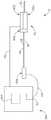
図1は、生検装置10及び真空制御モジュール400を含む例示的な生検システム2を示す。本実施形態の生検装置10は、図2−3に示すように、プローブ100及びホルスタ200を含む。針110はプローブ100から遠く延長され患者の組織に挿入されて組織サンプルを得る。このような組織サンプルは、以下でより詳細に説明されるように、プローブ100の近位端部で組織サンプルホルダ300に沈殿される。本明細書で「ホルスタ(holster)」という用語の使用はホルスタ200の任意の部分に挿入されるプローブ100の任意の部分を必要とすると読まれてはならないことを理解するべきである。本実施形態で、ホルスタ200は、プローブ100をホルスタ200に解除可能に固定するためにプローブ100のシャシー106によって収容される一対のプロング(prongs)208を含む。特に、プローブ100はホルスタ200に対してその最終位置の近くでホルスタ200の最上部に位置し、プローブ100は末端部に滑り落ちてプロング208に完全に結合される。また、プローブ100はユーザが両側タブ104を同時に加圧してプローブ100をホルスタから後方に引っ張ることができるようにプロング208を分離させるために内向に加圧されることができる1セットの弾性タブ104を使用してプローブ100をホルスタ200から分離する。もちろん、プローブ100とホルスタ200の分離可能な結合を提供するために多様な他の類型の構造、構成要素、フィーチャー(feature)(例えば、ベイオネットマウント、ラッチ、クランプ、クリップ、スナップフィッティングなど)が用いられてもよい。また、一部の生検装置10で、プローブ100及びホルスタ200は2つの構成要素が分離されることができないように単一構造又は一体構造であってもよい。単なる例示として、プローブ100及びホルスタ200が分離可能な構成要素として提供されるバージョンで、プローブ100は一回用(使い捨て)構成要素として提供されてもよいが、一方で、ホルスタ200は再使用可能な構成要素として提供されてもよい。プローブ100とホルスタ200の間の他の適した構造的及び機能的関係は本明細書の教示を考慮すれば当業者に明白であろう。I. Overview of Exemplary Biopsy System FIG. 1 shows an
生検装置10の一部変形例は、プローブ100がホルスタ200と結合される時を検出するように構成されたプローブ100及び/又はホルスタ200内の1つ以上のセンサ(図示せず)を含むことができる。このようなセンサ又は他のフィーチャーは特定の類型のプローブ100及びホルスタ200のみが共に結合されるように許容することができる。付加的に又は代案的には、このようなセンサは適切なプローブ100とホルスタ200が共に結合されるまでプローブ100及び/又はホルスタ200の1つ以上の機能を作動不能にするよう構成されることができる。単なる1つの例示的な実施形態で、プローブ100はホルスタ200と結合される時、ホルスタ200内のホール効果センサ(図示せず)又は一部の他のタイプのセンサによって検出される磁石(図示せず)を含む。さらに他の単なる例示的な例として、RFID技術を使用して伝導性表面又は電極の間の物理的接触を利用して及び/又は当業者に明白な数多くの他の方式でプローブ100とホルスタ200の結合が検出されてもよい。本願での教示の観点から本技術分野の当業者に理解されるであろう。もちろん、このようなセンサ及び特徴は必要に応じて変更又は省略されてもよい。 Some variations of
本実施形態の生検装置10は、テーブル又は固定物に装着され、定位的誘導下で用いられるように構成される。もちろん、超音波誘導、MRI誘導、PEM誘導、BSGI誘導又は他の方法で生検装置10が代わりに用いられてもよい。生検装置10は、生検装置10がユーザの片手で操作されることができるようにサイズ合わせ及び構成されることができることを理解するべきである。特に、ユーザは片手だけを使用して生検装置10を掴んで針110を患者の乳房に挿入して患者の乳房内で1つ又は複数の組織サンプルを収集できる。代案的には、ユーザは1つ以上の手及び/又は任意の好ましい補助装置で生検装置10を把握できる。一部の設定で、ユーザは、針110を患者の乳房に一度のみ挿入することによって複数の組織サンプルを捕獲できる。このような組織サンプルは組織サンプルホルダ300に空気圧式で沈殿されることができ、後で分析のために組織サンプルホルダ300から回収され得る。本願に記述された例は時々患者の乳房から生検サンプルを獲得することを言及するが、生検装置10は患者の解剖学(例:前立腺、甲状腺等)で多様な他の目的及び多様な他の部分で多様な他の手順で用いられてもよいことを理解するべきである。生検装置10の多様な例示的な構成要素、フィーチャー、構成及び作動は、以下でより詳細に説明される。他の適切な構成要素、特徴、構成及び動作は本明細書の教示を考慮すれば当業者に明白であろう。 The
II.例示的なホルダ
図3に示すように、本例のホルスタ200は、共に固定される上部ハウジングカバー202、側面パネル204及びハウジングベース206を含む。ギア212,230は上部ハウジングカバー202を介して露出され、プローブ100とホルスタ200が共に結合される時、プローブ100のギア130,140、特にギア230,140は針110内のカッタ150の作動組立体を駆動させる。ギア212,130は針110を回転させるために使用される。ギア240はホルスタ200の近位端部に位置してプローブ100のギア182と噛み合って組織サンプルホルダ300のマニフォールド310を回転させる。II. Exemplary Holder As shown in FIG. 3, the
前述のように、ギア212の回転はプローブ100に対する針110の回転を提供する。本例で、ギア212はノブ210を回転させることによって回転される。特に、ノブ210はノブ210の回転がギア212を回転させるように一連のギア(図示せず)及びシャフト(図示せず)によってギア212と結合される。第2ノブ210はホルスタ200の他側から延長される。単なる例として、米国出願公開番号第2008/0214955号の教示に従って針回転機構が構成されることができ、この出願の開示内容は本願に参照として引用されている。さらに他の単なる例示的な実施形態として、米国出願公開番号第2010/0160819号の教示に従って針回転機構が構成されることができ、この出願の開示内容は本願に参照として引用されている。一部の他のバージョンで、針110はモータによって回転される。さらに他の変形で、針110はサムホイール116を回転させることによって単純に回転される。針110の回転が提供され得る多様な他の適切な方法が本明細書の教示の観点から当業者に明白であろう。また、一部のバージョンは針110の回転を提供しなくてもよいことを理解するべきである。 As mentioned above, rotation of
また、ホルスタ200は、針110及び発射針110と遠位で結合する発射ロッド226及びフォーク222を含む。単なる例として、このような発射は生検装置10が患者の乳房に隣接するチップ112を具備した定位定着テーブル固定装置又は他の固定装置に装着される場合に有用な場合があり、その結果、針110を患者の乳房へ誘導する。針発射機構はプローブ100の固定された構成要素に対して任意の適切な距離でチップ112を駆動させるために任意の適切な運動範囲によって針110を駆動するように構成されることができる。
本実施形態で、針発射機構は、発射ロッド226及び発射フォーク222を介して針110と結合される。発射ロッド226と発射フォーク222は共に一体として固定される。発射フォーク222は針110のハブ部材120をそこに収容する一対のプロング224を含む。針110が発射ロッド226及びフォーク222と一体で移動するようにプロング224が環状フランジ118とサムホイール116の間に位置する。それにもかかわらず、プローブ100がホルスタ200と結合される時、フォーク222がハブ部材120に容易に固定されることができるようにプロング224はハブ部材120を除去可能に収容し;その結果、プローブ100がホルスタ200から分離される時、ハブ部材120はフォーク222から容易に除去されることができる。プロング224はハブ部材120がプロング224の間で回転できるように構成される。他の適切な構成要素、構成及び関係は本明細書の教示を考慮すれば当業者に明白であろう。本実施形態の針発射機構の内部構成要素は2014年10月14日に発行された「自動化された針発射を有する生検装置」という名称の米国特許第8,858,465号(この開示は本願に参照として引用される)に記載のように構成されて配列される。 In this embodiment, the needle firing mechanism is coupled to
ホルスタ200はギア230,240を駆動して組織サンプルホルダ300のカッタ150及び回転マニフォールド310を回転及び平行移動させるモータ(図示せず)を含む。また、ホルスタ200は、発射ロッド226を駆動して針110を装着又は発射するように作動可能なモータ(図示せず)を含む。本明細書で言及された全てのモータは本例でホルスタ200内に含まれ、ケーブル90を介して真空制御モジュール400から電力を供給される。また、データはケーブル90を介して真空制御モジュール400とホルスタ200の間で通信され得る。以下でより詳細に説明されるように、このようなデータは制御モジュール400に統合されたタッチスクリーン410上に特定のグラフィックユーザインタフェーススクリーンを表示するために制御モジュール400によって用いられてもよい。一部の他のバージョンで、1つ以上のモータはホルスタ200及び/又はプローブ100内に位置する1つ以上のバッテリによって電力が供給される。したがって、ここで説明された他の構成要素のように、ケーブル90は単なる選択的なものであることを理解するべきである。さらに他の単なる例示的な変形として、ケーブル90は加圧流体媒体をホルスタ200に伝達する導管で代替されることができるように空圧駆動されることができる。さらに他の単なる例示的な変形として、ケーブル90はホルスタ200の外部に位置するモータによって駆動された1つ以上の回転駆動ケーブルを含むことができる。2つ又は3つのモータが単一モータとして結合されてもよいことを理解するべきである。多様なモータが駆動されることができる他の適切な方法は本明細書の教示の観点から当業者に明白であろう。
III.例示的なプローブ
実施形態のプローブ100は、組織サンプルを得るために患者の組織内に挿入されるプローブ100から遠位方向に延長される針110を含む。これらの組織サンプルはプローブ100の近位端部で組織サンプルホルダ300に沈殿される。図1に示すように、真空制御モジュール400は、真空、食塩水、大気、及び排気を、プローブ100に選択的に提供するように作動可能なバルブアセンブリ500及びチューブ20,30,40,60を介して、プローブ100と連結されている。本実施形態のバルブ組立体の内部構成要素は、2013年8月22日に公開された「生検装置バルブアセンブリ」という名称の米国出願公開番号第2013/0218047に開示されており、この開示は本願に参照として含まれる。III. Exemplary
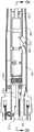
図1−6に示すように、プローブ100は、共に固定されるシャシー106及び上部ハウジング102を含む。図3に最もよく示すように、ギア140はシャシー106の開放部107を介して露出し、プローブ100でカッタ作動機構を駆動するように作動可能である。図3に示すように、さらに他のギア130はシャシー106を介して露出され、以下でより詳細に説明される針110を回転させるように作動可能である。プローブ100及びホルスタ200が共に結合される時、プローブ100のギア140はホルスタ200の露出されたギアと噛み合う。同様に、プローブ100のギア130はプローブ100とホルスタ200が共に結合される時、ホルスタ200の露出されたギア212と噛み合う。 As shown in FIGS. 1-6, the
A.例示的な針組立体
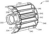
本例の針110は、組織貫通チップ112、チップ112に隣接するように位置した側面開口114及びハブ部材120を有するカニューレ113を含む。組織貫通チップ112は多量の力を要求することなくチップ112の挿入以前に組織に予め形成される必要がない組織を貫通するように構成される。代案的には、所望する場合は、チップ112は鈍くて(例えば、丸い、平たい等)よい。単なる例として、チップ112は2014年8月12日に発行された「生検装置用針組立体及びブレード組立体」という名称の米国特許第8,801,742号(この開示は本願に参照として引用される)の任意の教示に従って構成されることができ、その開示内容は本願に参照として引用されている。さらに他の単なる例示的な例として、チップ112は本明細書で参考文献として引用された米国出願公開番号第2013/0150751号の教示のうち少なくとも一部に従って構成されることができる。チップ112に用いられ得る他の適切な構成は本明細書の教示を考慮すれば当業者に明白であろう。A. Exemplary Needle Assembly The
側面開口114は、装置10の作動中に突出された組織を収容できる大きさである。鋭い末端エッジ152を有する管形カッタ150は針110内に位置する。カッタ150は側面開口114を介して突出された組織から組織サンプルを切断するために針110及び 側面開口114の先に対して回転及び並進運動するように操作できる。例えば、カッタ150は伸張された位置から収縮された位置へ移動され、組織がそれを介して突出できるように側面開口114を「開放」できる。後退した位置から突出された組織を切断するために延長された位置に戻る。以下でより詳細に述べられるように、針110は針110の長さ方向軸を中心に任意の所望の各位置で側面開口114を配向させるために回転されることができる。このような針110の回転はハブ部材120によって本例で容易になり、これはより詳細に後述される。 The
図6に最もよく図示されたように、また、針110は、チップ112の近位部分から近位方向に延長される縦方向壁190を含む。この例で、壁190はカニューレ113の全体長さに沿って延長されないが、所望する場合は、壁190がカニューレ113の全体長さを延長できることを理解するべきである。壁190はカッタ150に対して側面かつ平行する第2ルーメン(lumen)192の遠位部分を限定する。カッタ150が図6に示すように最も近位位置にある時、カッタ150の遠位切削エッジ152の位置に隣接する縦方向位置で壁近位が終結される。カッタ150の外部及びカニューレ113の内部は共に壁190の近位端部に隣接する針110の長さで第2ルーメン192の近位部分を限定する。 As best illustrated in FIG. 6,
壁190は第2ルーメン192と壁190の上及び側面開口114下のカニューレ113内の領域の間に流体連通を提供する複数の開放部194を含む。これはより詳細に後述されるように、第2ルーメン192とカッタ150の内部によって形成されたルーメン151の間の流体連通を提供する。開放部194は少なくとも1つの開放部194が側面開口114の遠位エッジから末端である縦方向位置に位置するように配列される。したがって、カッタ150のルーメン151と第2ルーメン192はカッタ150が側面開口114の遠位エッジの縦方向位置に対して遠位の縦方向位置であるカッタ150の遠位切削エッジの長さ方向位置に位置する位置に前進しても流体連通状態に維持されることができる。このような構成の一例は、2011年4月5日に発行された「自動化された生検及び軟組織収集方法及び装置」という名称の米国特許第7,918,803号に開示されており、その開示内容は本願に参照として含まれる。もちろん、ここに記述された任意の他の構成要素と同様に、任意の他の適切な構成が用いられてもよい。 The wall 190 includes a plurality of
針110内には複数の外部開放部(図示せず)が形成されてもよく、第2ルーメン192と流体連通されてもよい。例えば、このような外部開放部は2007年2月8日に公開された「真空補助下出血調節が可能な生検装置」という名称の米国特許公開番号第2007/0032742号の教示に従って構成されることができ、その開示内容は本願に参照として含まれる。もちろん、本明細書に説明された他の構成要素と同様に、針110内のこのような外部開放部は単なる選択的なものである。 A plurality of external openings (not shown) may be formed in the
本実施形態のハブ部材120は、ハブ部材120と針110が互いに一体で回転して並進するように針110に対してオーバーモールドされる。単なる例として、針110は金属で形成されることができ、ハブ部材120は針110に対してオーバーモールドされたプラスチック材料で形成されてハブ部材120を針110に一体的に固定及び形成できる。その代わりに、ハブ部材120及び針110は任意の他の適切な材料で形成されることができ、任意の他の適切な方式でともに固定されてもよい。ハブ部材120は、環状フランジ118及びサムホイール116を含む。ギア130は、ハブ部材120の近位部分150上にスライド移動可能に同軸に配置されてハブ部材120に固定されギア130が回転すると、ハブ部材120と針110が回転するようになり;しかし、ハブ部材120と針110はギア130に対して並進運動できる。ギア130はギア212によって回転可能に駆動される。代案的には、針110はサムホイール116を回転させることによって回転されてもよい。針110の受動回転が提供され得る多様な他の適切な方法が本明細書の教示の観点から当業者に明白であろう。また、針110の回転は、ここに引用された多様な参考文献に記載された多様な形態の自動針回転を含む多様な方式で自動化できることを理解するべきである。 The
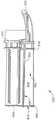
図4−7に示すように、マニフォールド122は、針110の近位端部に提供される。マニフォールド122は中空内部124を形成し中空内部124と流体連通するポート126を含む。図6に最もよく示すように、中空内部124は、さらに、針110の第2ルーメン192と流体連通する。ポート126は、マニフォールド122が第2ルーメン192とチューブ46の間に流体連通を提供するようにチューブ46と結合される。さらに、針110が針110の発射又は針110の再配置のような各々の場合にマニフォールド122に対して並進及び/又は回転しても、マニフォールド122は、針110の外部に対して封止され、マニフォールド122が第2ルーメン192とチューブ46の間に流体密カップリングを提供する。 As shown in FIGS. 4-7, the manifold 122 is provided at the proximal end of the
図4に示すように、針110には除去可能なカバー115が提供され得る。本実施形態のカバー115はサムホイール116と結合してカバー115を針110に除去可能に固定するように構成された弾性的に偏向されたラッチ117を含む。カバー115は、チップ112との不注意な接触から生検装置10のユーザを保護するようにラッチ117がサムホイール116と噛み合う時、チップ112を覆うように構成される。カバー115は、さらに、カニューレ113に対して封止するためにカバー115の近位端部及び/又は遠位端部の近くに1つ以上のワイパーシールを含むことができる。単なる例として、カバー115はその開示内容が本願に参照として引用されている米国出願公開番号第2013/0150751号の教示に従って構成されることができる。カバー115に対する多様な他の適切な構成が本明細書の教示の観点から当業者に明白であろう。もちろん、必要であれば、カバー115は単純に省略されてもよい。また、本明細書に記載された他の構成要素と同様に、針110は多様な方法で変更、改造、置換又は補充されることができることを理解するべきである。その針110は多様な代案的な特徴、構成要素、構成及び機能を有することができる。例えば、針110は本願に参照として引用された米国出願公開番号第2008/0214955号及び/又は本願に引用された任意の他の参考文献の開示内容に従って構成されることができる。 As shown in FIG. 4, the
B.例示的なカッタ組立体
前述のように、カッタ150は、針110に対して同時に並進運動及び回転して側面開口114を介して突出した組織から組織サンプルを切断する。図5−7に最もよく示すように、カッタ150はカッタ150に一体で固定されるオーバーモールド160を含む。オーバーモールド160は、オーバーモールド160の中央領域に一般に平滑かつ円筒状である遠位部分166、ねじ162及びオーバーモールド160の近位部分に沿って延長される1セットの六角形平坦部164を含む。遠位部分166は、マニフォールド122内に延長される。カッタ150が並進移動され相手回転される場合にもマニフォールド122が第2ルーメン192とチューブ46間の流体密結合を維持するようにマニフォールド122は末端部分166を封止する。B. Exemplary Cutter Assembly As mentioned above, the
ギア140は、平坦部164上に位置し平坦部164を補完する1セットの内部平坦部(図示せず)を含む。したがって、ギア140が回転される時ギア140はオーバーモールド160及びカッタ150を回転させる。しかし、オーバーモールド160は、ギア140に対してスライド可能で、ギア140がシャシー160に対して縦方向に固定されているにもかかわらずカッタ150はシャシー160に対して並進運動できる。ギア140はギア230によって回転される。図7−8に最もよく図示されたように、ナット142はオーバーモールド160のねじ162と関連する。特に、ナット142はオーバーモールド160のねじ162と噛み合う内部ねじ144を含む。ナット142はシャシー160に対して固定式で固定される。したがって、ギア140がカッタ150及びオーバーモールド160を回転させる時、カッタ150はねじ144,162の噛み合いによって同時に並進する。一部の変形例で、前述したカッタ作動構成要素は本願に参照として引用された米国出願公開番号第2008/0214955号の記載内容から具現され得る。さらに他の単なる例示的な例として、カッタ150は空圧モータなどを使用して回転及び/又は変換され得る。カッタ150が作動されることができるさらに他の適合した方法は本明細書の教示の観点から当業者に明白であろう。
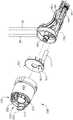
C.例示的な組織サンプルホルダアセンブリ
本実施形態の組織サンプルホルダ300は、カッタ150によって切断されてカッタ150のルーメン151を介して近位に伝達される組織サンプルを収容するように構成された複数の個別チャンバを提供する。特に、以下でより詳細に説明されるように、組織サンプルホルダ300は、マニフォールド310と除去可能に結合される組織収容トレー330を含む。マニフォールド310は、回転部材180のグリップ形状部184と除去可能に結合される。回転部材180は、シャシー106に対して縦方向に固定されシャシー106に対して回転可能である。回転部材180は、プローブ100とホルスタ200が共に結合される時、ホルスタ200のギア240と噛み合う一体型ギア182を含む。ギア182,240は、マニフォールド310を回転させるように協力して以下でより詳細に説明されるようにカッタ150のルーメン151に対して組織チャンバをインデクシングする。透明カバー302は、マニフォールド310の近くに位置しシャシー106に除去可能に固定される。ベイオネットフィーチャーがカバー302とシャシー106の間のカップリングを提供する間、任意の適切な類型のカップリングが用いられてもよいことを理解するべきである。マニフォールド310は、カバー302内で自由に回転できる。しかし、カバー302がシャシー106から除去される時、マニフォールド310がシャシー106に対して分離されることができるようにマニフォールド310はカバーと噛み合う。換言すれば、マニフォールド310は、シャシー106からカバー302を結合及び除去することによってシャシー106に対して選択的に結合及び除去されることができる。C. Exemplary Tissue Sample Holder Assembly
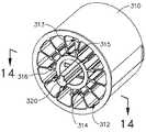
1.例示的なマニフォールド
図12−14によく示すように、本実施形態のマニフォールド310は、マニフォールド310を介して長さ方向に延長されマニフォールド310の中心軸を中心に角をなす通路312形状の多数のチャンバを限定する。図14に最もよく図示されたように、側面凹部314は各々の通路312の遠位部分と関連する。棚316は各通路312と関連側面凹部314の間の境界を確定する。後述するように、通路312はトレー330を収容し、凹部314は空気通路を提供する。追加的な通路313及び凹部315はプラグ370と関連づけられ、これは以下でより詳細に説明される。マニフォールド310は、さらに、グリップ形状部184と除去可能に結合するように構成された中央シャフト320を含む。中央シャフト320は、上述のようにシャシー106とカバー302を結合する時、グリップ形状部184と結合する。中央シャフト320とグリップ形状部184の間の結合はギア182の回転時にマニフォールド310の回転を提供する。1. Exemplary Manifold As best shown in FIGS. 12-14, the
図10−11に最もよく図示されたように、シャシー106の遠位端部に封止部材170が提供されてマニフォールド310の遠位面と接触する。本実施形態で、封止部材170はゴムを含むが、任意の他の適切な材料(ら)が用いられてもよいことを理解するべきである。封止部材170は、カッタ150を収容しカッタ150の外部に対して封止する縦方向に延長するカッタシール172を含む。カッタ150の近位端部はカッタ150の全体移動範囲にわたってカッタシール172内に維持される。カッタシール172は、カッタ150の回転及び並進移動を含んでこの全範囲の運動中にカッタ150に対して流体密を維持する。開放部174は、カッタシール170の近位端部に位置する。この開放部174は12時方向の位置にある通路312,313と整列されるように構成される。他の開放部176は、開放部174の下に位置する。開放部176は、12時方向位置にある凹部314,315のうちいずれか1つと整列されるように構成される。図9及び図11に最もよく図示されたように、開放部176は、チューブ20と結合されたポート178と流体連通する。したがって、封止部材170はチューブ20と凹部314,315が12時方向に位置にある流体連通を提供する。以下でより詳細に説明されるように、マニフォールド310は、12時方向の位置でこのような凹部314,315と関連通路312,313の間に流体連通をさらに提供する。これによってカッタ150のルーメン(lumen)151が形成される。換言すれば、封止部材170及びマニフォールド310は協力してチューブ20とカッタ150のルーメン151の間に流体連通を提供し、これによって通路312,313及び凹部314,315は12時方向に位置する。本実施形態の封止部材170は、マニフォールド310が封止部材170に対して回転される場合にもマニフォールド310の遠位面に対して流体密を維持することを理解するべきである。 As best illustrated in FIGS. 10-11, a sealing
2.例示的な組織ホルダトレー
前述のように、組織サンプルホルダトレー330は、マニフォールド310を移動可能に結合するように構成される。図15−17に最もよく示すように、本例の各組織サンプルホルダトレー330は、グリップ332、近位壁334及び近位壁334から遠位方向に延長される複数のストリップ340を含む。ストリップ340は、マニフォールド310の関連通路312内に挿入されるように大きさが定められて構成される。各ストリップ340は、一対の側壁344と床342を含む。各々の一対の側壁344と床342は共に対応する組織サンプルチャンバ346を形成する。開放部348は、各々の組織サンプルチャンバ346の遠位端部に提供される。開放部は封止部材170の開放部174と一致するように大きさ及び位置が設定される。したがって、カッタ150のルーメン151は12時方向の位置にある通路312に挿入されたストリップ340の組織サンプルチャンバ346と流体連通する。図11に最もよく示すように、ストリップ340は各々のストリップ340の遠位端部がマニフォールド310の相応する棚316から支持部を収容するように構成される。各々の床342はストリップ340の組織サンプルチャンバ346とストリップ340と関連づけられた通路312の側面凹部314の間の流体連通を提供する複数の開放部345を含む。したがって、真空、大気などは側面凹部314、開放部345及び組織サンプルチャンバ346を介してカッタ150のルーメン151に追加的に伝達される。生検装置10の作動中に、カッタ150の遠位エッジ152によって切断された組織サンプルはカッタ150のルーメン151を介して近位に伝達され、カッタ150のルーメン151と整列される組織サンプルチャンバ346内に沈殿される。生検装置10の作動中に複数の組織サンプルが互いに異なる組織サンプルチャンバ346に個別的に沈殿されることができるようにマニフォールド310は組織サンプルチャンバ346をカッタ150のルーメン151と連続的に整列させるように回転される。ルーメン151を介して引っ張られる体液及び食塩水などは組織サンプルホルダ300及びチューブ20を通過して真空キャニスタ70に最終的に沈殿されるであろう。2. Exemplary Tissue Holder Tray As mentioned above, the tissue
各ストリップ340は、さらに、ストリップ340が通路312内に完全に挿入される時、通路312の内部に対して封止する一対のワイパーシール343,349を含む。ワイパーシール343,349は、組織サンプルチャンバ346のための流体密を提供してマニフォールド310からストリップ340の除去に対する摩擦抵抗を提供する。グリップ332は、組織サンプルチャンバ346に沈殿された組織サンプルを回収したり直接観察するために生検手順の間又は以後にマニフォールド310からストリップ340の除去を容易にするよう構成される。トレー330は、さらに、各組織サンプルチャンバ346と関連づけられた数字表示338を含む。また、トレー330はトレー330の平坦化を容易にするピンチ領域336を含む。特に、ピンチ領域336は、トレー330がマニフォールド310内に挿入するためのアーチ型構成を形成できるように十分な柔軟性を提供する;トレー330がトレー330内の組織サンプルの検査のためにマニフォールド310から除去された後、トレー330のような一般に平らな形状を形成できるようにする。 Each
マニフォールド310及び/又はトレー330は、数多くの他の方式で構成されることができることを理解するべきである。単なる例として、マニフォールド310及び/又はトレー330は、本明細書に参照として含まれた米国出願公開番号第2008/0214955号の教示のうち少なくとも一部に従って構成されることができる。さらに他の単なる例示的な実施形態として、マニフォールド310及び/又はトレー330は、本明細書に参照として含まれた米国出願公開番号第2010/0160824号の教示のうち少なくとも一部に従って構成されることができる。組織サンプルホルダ300は、必ずしもカッタ150のルーメン151と同軸にチャンバ346を配置する必要はないということを理解するべきである。組織サンプルホルダ300は、他の適切な方式でカッタ150に対してチャンバ346をインデクシングできる。例えば、チャンバ346は、ルーメン151の軸から常にオフセットされた軸に沿って、ルーメン151の軸に対して傾斜したり垂直である軸に沿って又は他の軸に沿って延長されることができる。同様に、マニフォールド310はルーメン151の軸に対して傾斜する又は垂直である軸を中心に回転できることを理解するべきである。本明細書の教示を考慮すれば当業者にはさらに他の適合した構成が明白であろう。 It should be appreciated that the manifold 310 and / or the
3.例示的な附属チャンバ及びプラグ
図12及び図18に最もよく図示されたように、上述のように、本例の組織サンプルホルダ300はマニフォールド310の専用通路313に収容されるプラグ370を含む。プラグ370はグリップ372及び縦方向延長本体374を含む。本体374は、通路313長さの一部を通って延長され、凹部315の近位端部に対応する縦方向位置で遠位に終結される。プラグ370は、プラグ370が通路313に完全に挿入される時、通路313の内部に対して封止する一対のシール376,378を含む。したがって、プラグ370が通路313に挿入される時、シール376,378は通路313を流体状態に維持させる。通路313は生検部位マーカーアプリケータのシャフトを収容するように構成される。通路313は、生検部位に薬などを伝達するための器具を受ける場合もある。単なる例として、通路313は、通路313と従来の薬剤伝達装置の間のインタフェースを提供するように構成されたアダプタを収容できる。そのようなアダプタ及び通路313のような通路に対する他の用途/構成の例は本明細書に参照として含まれる米国出願公開番号第2008/0221480号に開示されている。プラグ370及び/又は通路313は、本明細書に参照として含まれる米国出願公開番号第2013/0041256号の教示のうち少なくとも一部に従って構成されて作動可能であってもよい。本明細書の教示を考慮すれば当業者にはさらに他の適合した構成が明白であろう。一部の他のバージョンで、プラグ370及び/又は通路313は単純に省略される。3. Exemplary Additional Chambers and Plugs As best shown in FIGS. 12 and 18, as described above, the
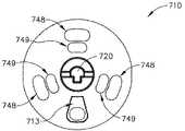
D.例示的な代替組織サンプルホルダアセンブリ
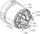
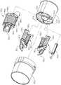
図19−29は、前述した組織サンプルホルダ300に類似している例示的な代替組織サンプルホルダ700を図示する。本実施形態の組織サンプルホルダ700は、カッタ150によって切断されカッタ150のルーメン151を介して近位に伝達される組織サンプルを収容するように構成された複数の個別チャンバを提供する。特に、以下でより詳細に説明されるように、組織サンプルホルダ700は、マニフォールド710と除去可能に結合される組織収容トレー730を含む。マニフォールド710は、回転部材180のグリップ形状部184と除去可能に結合される。回転部材180は、シャシー106に対して縦方向に固定されてシャシー106に対して回転可能である。回転部材180は、プローブ100とホルスタ200が共に結合される時、ホルスタ200のギア240と噛み合う一体型ギア182を含む。ギア182,240は、マニフォールド710を回転させるように協力して、以下でより詳細に説明されるように、カッタ150のルーメン151に対して組織チャンバをインデクシングする。透明なカバー702は、マニフォールド710の近くに位置しシャシー106に除去可能に固定される。ベイオネットフィーチャーがカバー702とシャシー106の間のカップリングを提供する間、任意の適切な類型のカップリングが用いられてもよいことを理解するべきである。マニフォールド710は、カバー702内で自由に回転できる。しかし、カバー702がシャシー106から除去される時、マニフォールド710がシャシー106に対して分離されることができるようにマニフォールド710はカバー702と噛み合う。換言すれば、マニフォールド710は、シャシー106からカバー702を結合及び除去することによってシャシー106に選択的に結合及び除去されることができる。D. Exemplary Alternative Tissue Sample Holder Assembly FIGS. 19-29 illustrate an exemplary alternative
図23及び図24に最もよく図示されたように、本例のマニフォールド710は、マニフォールド710を通って縦方向に延長されマニフォールド710の中心軸を中心に角をなすように配列された通路712形状の多数のチャンバを形成する。マニフォールド310とは異なって、本例のマニフォールドは、マニフォールド310の凹部314及び棚316に類似している構造を省略する。その代わりに、以下でより詳細に説明されるように、通路712は空圧通路を形成するトレー730及びトレー730を収容する。同様に、単一通路713(ただし、凹部は無い)だけがプラグ770と関連づけられ、これはまた以下でより詳細に説明される。マニフォールド710は、さらに、グリップ形成部184と除去可能に結合するように構成された中央シャフト720を含む。中央シャフト720は、ギア182の回転時、マニフォールド710の回転を提供するためにシャシー106とカバー702を結合する時、グリップ形状部184と結合する。 As best shown in FIGS. 23 and 24, the
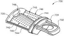
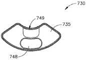
前述のように、組織サンプルホルダトレー730は、マニフォールド710と移動可能に結合するように構成される。図26−29に最もよく図示されたように、本例の各組織サンプルホルダトレー730は、近位壁734から遠位壁735まで遠位方向に延長されたグリップ732、近位壁734及びストリップ740を含む。ストリップ740は、マニフォールド710の単一通路712内に挿入されるように大きさが定められて構成される。組織サンプルホルダトレー330とは異なって、組織サンプルホルダトレー730は、以下でより詳細に説明されるように、マニフォールド710の全体通路712を占める。ストリップ740は、一対の側壁744と床742を含む。側壁744及び床742は共に対応する組織サンプルチャンバ746を限定する。また、側壁744及びバー742は共に組織サンプルホルダトレー330のストリップ340とは異なって空圧通路714を形成する。特に、床742が遠位方向に延長されるとともに床742は上方に傾斜している。それに対応して、側壁744は床742の上方に向かって傾斜を収容するために床742と結合する角のあるエッジを有する。このような曲率は単なる選択事項ではあるが、床742は空圧通路の体積を追加的に増加させる曲率を含むことができる。 As mentioned above, the tissue
組織サンプルホルダトレー730の遠位壁735は、前述した封止部材170と結合できる2つの開放部748,749を提供する。開放部748は、封止部材170の開放部174と一致するように大きさ及び位置が設定される。したがって、カッタ150のルーメン151は、12時方向の位置にある通路712に挿入されたストリップ740の組織サンプルチャンバ746と流体連通する。同様に、開放部749は、空圧通路714と真空を連通させるために封止部材170の開放部176と一致するように大きさ及び位置が設定される。各々の側壁744及び床742は、ストリップ340の組織サンプルチャンバ346と空圧通路714の間の流体連通を提供する複数の開放部745を含む。したがって、チューブ20を介して開放部176に伝達された真空、大気空気などは空圧通路714、開放部745及び組織サンプルチャンバ746を介してカッタ150のルーメン151に追加的に伝達される。生検装置10の作動中に、カッタ150の遠位エッジ152によって切断された組織サンプルはカッタ150のルーメン151を介して近位に伝達され、カッタ150のルーメン151と整列された組織サンプルチャンバ746に沈殿される。生検装置10の作動中に複数の組織サンプルが互いに異なる組織サンプルチャンバ746に個別的に沈殿されることができるようにするために、マニフォールド710は回転されてカッタ150のルーメン151と組織サンプルチャンバ746を連続的に整列させる。代案的には、各々の組織サンプルチャンバ746は、新しい組織サンプルチャンバ746をカッタ150のルーメン151と整列させるために回転される前に所定個数の組織サンプルを収集できる。それにもかかわらず、ルーメン151を介して引っ張られる体液及び食塩水などは組織サンプルホルダ700及びチューブ20を通過して真空キャニスタ70に最終的に沈殿される。The
マニフォールド710及び/又はトレー730は、数多くの他の方式で構成されることができることを理解するべきである。単なる例として、マニフォールド710及び/又はトレー730は、本明細書に参照として引用された米国出願公開番号第2008/0214955号の教示のうち少なくとも一部に従って構成されることができる。他の単純な例示として、マニフォールド710及び/又はトレー730は、本明細書に参照として含まれた米国出願公開番号第2010/0160824号の教示のうち少なくとも一部に従って構成されることができる。組織サンプルホルダ700は、必ずしもカッタ150のルーメン151と同軸にチャンバ746を位置させる必要はないということを理解するべきである。組織サンプルホルダ700は、他の適切な方式でカッタ150に対してチャンバ746をインデクシングできる。例えば、チャンバ746は、ルーメン151の軸から常にオフセットされた軸に沿って、ルーメン151の軸に対して傾斜している若しくは垂直する軸に沿って、又は他の軸に沿って延長されることができる。同様に、マニフォールド710は、ルーメン151の軸に対して斜め又は垂直の軸を中心に回転できることを理解するべきである。しかし、他の構成で、マニフォールド710は、プローブ100又はホルスタ200内のモータによって回転又はインデクシングされてもよいことを理解するべきである。しかし、さらに他の例で、組織サンプルホルダは、ユーザの手によって手動で回転されてもよい。単なる例として、このような手動で回転可能なマニフォールド710は、2014年9月24日に出願された「MRI生検システム(MRI Biopsy System)」という名称の米国特許出願番号第62/054,523号(この開示は本願に参照として含まれる)の教示のうち少なくとも一部に従って構成されることができる。本明細書の教示を考慮すれば当業者にはさらに他の適合した構成が明白であろう。 It should be appreciated that the manifold 710 and / or
図24に最もよく図示され前述したように、本例の組織サンプルホルダ700は、マニフォールド710の専用通路713に収容されるプラグ770を含む。プラグ770は、グリップ772及び縦方向延長本体774を含む。本体774は、通路長さ713の一部を通って延長される。プラグ770は、さらに、プラグ770が通路713に完全に挿入される時、通路713の内部に対して封止する前述したシール376,378に類似している多数のシールを含むことができる。前述した通路313に類似している通路713は、生検部位マーカーアプリケータのシャフトを収容するように構成される。通路713は、生検部位に薬などを伝達するための器具をさらに受ける場合もある。単なる例として、通路713は、通路713と従来の薬剤伝達装置の間のインタフェースを提供するように構成されたアダプタを収容できる。そのようなアダプタ及び通路713のような通路に対する他の用途/構成の例は、本明細書に参照として引用された米国出願公開番号第2008/0221480号に開示されている。プラグ770及び/又は通路713は、本明細書に参照として引用された米国出願公開番号第2013/0041256号の教示のうち少なくとも一部に従って構成されて作動可能であってもよい。本明細書の教示を考慮すれば当業者にはさらに他の適合した構成が明白であろう。一部の他のバージョンで、プラグ770及び/又は通路713は単純に省略される。 As best shown in FIG. 24 and described above, the
単なる例示として、組織サンプルホルダ300,700は、2014年11月13日に出願された米国特許出願番号第14/469,761号(発明の名称「生検装置用組織収集組立体」)に開示されている内容に従って構成されることができる。組織サンプルホルダ300,700がとれるさらに他の適合した形態は本明細書の教示を考慮すれば当業者に明白であろう。 By way of example only, a tissue sample holder 300,700 is disclosed in US patent application Ser. No. 14 / 469,761 filed Nov. 13, 2014 (Title Collection Assembly for Biopsy Devices). It can be configured according to what is being done. Still other suitable configurations for
IV.例示的なグラフィックユーザインタフェース
A.例示的な初期設定画面
図30−34は、生検システム2のセットアップする間にタッチスクリーン410上にディスプレイされることができる例示的なスクリーン1000,1020,1040,1060,1080を図示する。特に、図30に示す画面1000は、ホルスタ200のグラフ表現1002及びプローブ100をホルスタ200に付着するためのテキスト命令1006を有するプローブ100のグラフィック表現1004を含む。スクリーン1000は、さらに、音量調整ボタン1008、明るさ調整ボタン1010及び設定調整ボタン1012を含む。本明細書で「ボタン」という用語が用いられるが、移動可能な特徴を有する電子機械的ボタンを必要とすると読まれてはならないことを理解するべきである。この用語は対話形アイコン及びフラットタッチスクリーンの他の特徴を含むことができる。ユーザが音量調整ボタン1008をタップすると、サブ−スクリーンがポップアップされてユーザが真空制御モジュール400によって放出されたオーディオフィードバックに対するボリュームレベルを選択できる。ユーザが明るさ調整ボタン1010をタップすると、ユーザがタッチスクリーン410の明るさレベルを選択できるようにサブ−スクリーンがポップアップされるであろう。ユーザが設定調整ボタン1012をタップすると、ユーザが真空制御モジュール400(例えば、言語等)に対する多様な設定を調整できるサブ−スクリーンがポップアップされるであろう。IV. Exemplary Graphic User Interface Exemplary Initialization Screens FIGS. 30-34 illustrate
ユーザがプローブ100をホルスタ200に付着した途端、タッチスクリーン410は自動的に図31に示すスクリーン1020に遷移する。したがって、真空制御モジュール400は、プローブ100がホルスタ200に付着される時を感知するように構成された回路を含むと理解するべきである。例えば、一部の例で、プローブ100は、磁石を含むことができ、ホルスタ200はプローブ100の磁石によって生成された磁場を検出するように構成されたセンサを含むことができる。このような回路がとれる多様な他の形態が本明細書の教示の観点から当業者に明白であろう。スクリーン1020は、ホルスタ200のグラフィック表現1022及びプローブ100のグラフィック表現1024を含み、トレースタイルを選択するためのテキスト命令1026を含む。本例で、ユーザは組織サンプルホルダ300又は組織サンプルホルダ700がプローブ100と結合されるか否かに基づいて「トレースタイル」を選択できる。スクリーン1020は、さらに、上述のように、音量調整ボタン1008、明るさ調整ボタン1010及び設定調整ボタン1012を含む。 As soon as the user attaches the
ホルスタ200に付着されたプローブ100で、トレー選択ボタン1028がスクリーン1020上に見える。特に、トレー選択ボタン1028は、2つのトレースタイル選択ボタン1030,1032及びデフォルトカップメニューボタン1034を含む。各々のトレースタイル選択ボタン1030,1032は前述した組職サンプルホルダアセンブリ300,700のうち1つをグラフィックで表す。したがって、用語「個別」は、組織サンプルホルダアセンブリ300内の各々の組織収容チャンバが1つのみの個別組織サンプルを保有するように構成されることを示す。同様に、「バルク」トレー選択ボタン1032は、前述した組織サンプルホルダアセンブリ700をグラフィックで表す。したがって、スクリーン1020はどの組織サンプルホルダアセンブリ300,700がプローブ100に付着されるかに関するユーザ入力を受信するように構成される。ユーザが与えられたトレースタイル選択ボタン1030,1032を選択すると、以下で詳しく説明されるように、ユーザは与えられたサンプルスクリーン1200,2200にタッチスクリーン410を切り替えるためにメニュー進行ボタン1036を押すことができる。ユーザがスタイル選択ボタン1030,1032のうち1つを押した時、その特定のスタイル選択ボタン1030,1032は明るく発光し、カラーを変更して及び/又は他の特定のスタイル選択ボタン1030,1032が活性化されたことを示す視覚的フィードバックを提供できる。付加的に又は代案的には、非活性のスタイル選択ボタン1030,1032は暗くしたり、カラーを変更したり及び/又は他の特定のスタイル選択ボタン1030,1032が活性化されていないことを示す視覚的フィードバックを提供できる。 With
個別トレー選択ボタン1030に関してここで用いられた「個別」符号は各組織サンプルチャンバ346が1つの単一組織サンプルのみを収容するように構成/使用されるように組織サンプルホルダ組立体300の使用を示す。同様に、バルクトレー選択ボタン1032に関する「バルク」符号は、各組織サンプルチャンバ746が複数の組織サンプルを収容するように構成/使用されるように組織サンプルホルダアセンブリ700の使用を示す。トレースタイル選択ボタン1030,1032は、本明細書で「個別」又は「バルク」トレー構成に対応すると言及されたが、他の例で、組織サンプルホルダ300,700は「個別」又は「バルク」に特徴づけられる場合もある。 The “individual” designations used herein with respect to the individual
デフォルトカップメニューボタン1034がユーザによって選択されると、タッチスクリーン410は図32に示すスクリーン1040へ移動する。スクリーン1040は、デフォルトトレースタイル選択ボタン1042、デフォルトカップタイプを選択するためのテキスト命令1044、確認ボタン1046及び取り消しボタン1048を含む。スクリーン1040は、さらに、上述のように、音量調整ボタン1008、明るさ調整ボタン1010及び設定調整ボタン1012を含む。デフォルトトレースタイル選択ボタン1042は、個別デフォルト選択ボタン1050、バルクデフォルト選択ボタン1052及びデフォルト選択ボタン1054を含む。個別デフォルト選択ボタン1050は、組織サンプルホルダアセンブリ300をグラフィックで表すものとして図示され、バルクデフォルト選択ボタン1052は、組織サンプルホルダアセンブリ700をグラフィックで表すものものとして図示された。したがって、ユーザは組織サンプルホルダアセンブリ300又は組織サンプルホルダアセンブリ700とともに、一般に生検システム2が使用されるということを表すために個別デフォルト選択ボタン1050又はバルクデフォルト選択ボタン1052を選択できる。これはユーザが組織サンプルホルダアセンブリ300又は組織ホルダアセンブリ700のみを使用する臨床環境で好ましい場合がある。デフォルトが選択された合、スクリーン1020は全体的にスキップされることができ、タッチスクリーン410は、上述したスクリーン1060に進むことができる。ユーザが好まない又は組織サンプルホルダアセンブリ300,700を相互交換可能に使用する場合、ユーザはデフォルト選択ボタン1050を選択できない。デフォルト選択ボタン1050がユーザによって操作されない場合、プローブ100がホルスタ200に付着される時、タッチスクリーン410はスクリーン1000からスクリーン1020へ進むであろう。ユーザがデフォルト設定を選択すると、ユーザは確認ボタン1046を押してデフォルト設定を格納してスクリーン1020に戻ることができる。代案的には、ユーザが単にデフォルト設定を取り消すことを望む場合は、ユーザはデフォルト設定を格納することなく取り消しボタン1048を押してスクリーン1020へ戻ることができる。 When the default
図33は、スクリーン1060を図示する。スクリーン1060は個別トレー選択ボタン1030がグラフィック的に結合されたことを除けばスクリーン1020と実質的に同じである。特に、個別トレー選択ボタン1030は、ユーザが個別トレー選択ボタン1030を選択したことを示す暗い外観を有すると図示されている。これに対して、バルクトレー選択ボタン1032は、図31に示すように維持される。個別トレー選択ボタン1030が選択されると、生検システムは、テキスト命令1062によって提示されたように初期化を準備がする。次いで、ユーザは、以下でより詳細に説明されるように、タッチスクリーン410をスクリーン1200に遷移させるメニュー進行ボタン1036を押すことによって生検システム2を初期化できる。 FIG. 33 illustrates the
図34は、スクリーン1080を図示する。スクリーン1080はバルクトレー選択ボタン1032がグラフィック的に結合されていることを除けばスクリーン1020と実質的に同じである。また、スクリーン1080は、一連のゲージ選択ボタン1084を含む。バルクトレー選択ボタン1032は、ユーザがバルクトレー選択ボタン1032を選択したことを示すために暗い外観を有するように図示されている。これに対して、個別トレー選択ボタン1030は図31に示すように維持される。 FIG. 34 illustrates the
ゲージ選択ボタン1084は、10ゲージ選択ボタン1086及び8ゲージ選択ボタン1088を含む。各ゲージ選択ボタン1086,1088は針110の可能なゲージ大きさに対応する。したがって、ユーザはプローブ100が具備する針110の実際のゲージ大きさに対応する適切なゲージ大きさを選択できる。選択されたゲージ選択ボタン1086,1088は、選択されたゲージ選択ボタン1086,1088の近くの暗いアウトラインを使用してグラフィックで表示されることができる。本例示で、10つのゲージ選択ボタン1086が選択された場合は同様に識別されることができるが、8つのゲージ選択ボタン1088が選択されると図示される。図34は、10ゲージ又は8ゲージの針110に対応するゲージ選択ボタン1084を具体的に示すが、他の例で、針110は任意の他のゲージ大きさを有してもよく、ゲージ選択ボタン1084は、本明細書の教示の観点から当業者に明白なように調整されることができることを理解するべきである。 The
バルクトレー選択ボタン1032を選択して適切なゲージ選択ボタン1086,1088を選択すると、生検システムがテキスト命令1082に表示されたように初期化を準備する。次いで、ユーザは、以下でより詳細に説明されるように、タッチスクリーン410をスクリーン2200に遷移させるメニュー進行ボタン1036を押すことによって生検システム2を初期化できる。 Selecting the bulk tray
図35は、生検システム2に対して前述したスクリーン1000,1020,1040,1060,1080を使用する設定手順1100のフローチャートを図示する。理解できるように、ブロック1102は、ユーザがスクリーン1000に関して上述したように、プローブ100をホルスタ200に付着する時、手順が開始されることを指示する。一旦、プローブ100が付着されると、ブロック1104は、ユーザがスクリーン1020に対して上述のように、12個の組織収容トレー330又は3つの組織収容トレー730のうちいずれか1つに対して構成された適切な組織サンプルアセンブリ300,700を選択できることを示す。このステップで、ユーザは、スクリーン1040と関連して上述したように、将来の手順のためにデフォルト組織サンプルアセンブリ300,700を選択的に選択できる。このようなステップは、図35に示すように点線で示すブロック1106で示す。 FIG. 35 illustrates a flow chart of a setting procedure 1100 using the
ブロック1110で表示されたように、組織サンプルホルダ組立体300の使用が選択されると、ユーザはブロック1112によって指示されたように、スクリーン1060に関して上述のように直接初期化を進めることができる。初期化の後、タッチスクリーン410は、図35で、ブロック1114によって指示されたように、組織サンプルホルダアセンブリ300が装着された場合にプローブ100に対応するサンプルスクリーン1200に自動的に転換されることができ、以下でより詳しく説明される。 Once the use of the tissue
ブロック1120に表示されたように、組織サンプルホルダ組立体700の使用が選択されると、ユーザは、ブロック1122によって指示されたように、プローブ100の適切な針ゲージを選択できる。本例で、ユーザはブロック1124及びブロック1126にそれぞれ表示された10ゲージ針又は8ゲージ針のうち1つを選択できる。このような選択は上述した画面1080に対応する。選択された特定針ゲージにかかわらず、ユーザは、図35のブロック1128によって表示され上述したように、スクリーン1080に対して初期化を開始することができる。一旦、初期化が完了すると、タッチスクリーン410は、図35でブロック1130によって指示するように、組織サンプルホルダアセンブリ300が装着される時、プローブ100に対応するサンプルスクリーン2200に自動的に転換でき、以下でより詳細に説明される。 Once the use of the tissue
B.12個のトレー組織サンプルホルダのための例示的なサンプルスクリーン
図36は、上述のように、スクリーン1060を図示する。以上で説明したように、スクリーン1060は初期化の前に表示される。初期化を開始するために、ユーザは、メニュー進行ボタン1036を押すことができる。初期化が開始されると、タッチスクリーン410は、図37に示すように、サンプルスクリーン1200に自動的に遷移する。サンプルスクリーン1200は、プローブ100が組織サンプルホルダアセンブリ300を備えている時、プローブ100を制御するように構成される。一部の例で、初期化は予め決定された量の時間を必要とする場合がある。したがって、初期化の間、サンプルスクリーン1200は暗くなるか、うす暗くなるか、あるいはユーザに初期化プロセスが依然として発生していることを表すために遮断されることができる。一部のバージョンで、そのような所定の時間量は5秒であってもよい。一部の他のバージョンで、予め決定された量の時間は用いられる特定制御モジュール400、用いられる特定制御モジュール400の内部構成要素、用いられる特定制御モジュールプローブ100、当業者に自明な任意の他の変数のような多様な変数に応じて増加又は減少する場合がある。B. Exemplary Sample Screen for Twelve Tray Tissue Sample Holder FIG. 36 illustrates
サンプルスクリーン1200は、カッタ制御領域1210、組織サンプルホルダ制御領域1260及び真空制御領域1280を含む。一般に、領域1210,1260,1280は与えられた機能がカッタ150、組織サンプルホルダ300又は制御モジュール400によって供給される真空を制御するか否かによって多様な生検システム2機能をグループ化する。このような生検システム2の機能は、各々の特定領域1210,1260,1280と関連して以下でさらに詳しく記述される。生検システム2の各機能が与えられた方式で構成されるが、他の例では代案的な組織体系が用いられてもよいことを理解するべきである。サンプルスクリーン1200は、さらに、音量調整ボタン1008、明るさ調整ボタン1010及び待機ボタン1202を含む。待機ボタン1202は、一般に生検システム2を待機モードに位置させるように動作可能に構成され、以下でより詳細に説明されるようにタッチスクリーン410を待機スクリーン1290に転換させる。 The
1.例示的なカッタインタフェース特徴
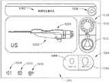
図37に示すように、スクリーン1200のカッタ制御領域1210は、針110の遠位端部のグラフィック表現1212、カッタ150のグラフィック表現1214、「開口設定」ボタン1218及び生検設定ボタン1219を含む。1. Exemplary Cutter Interface Features As shown in FIG. 37, the
ユーザが「開口設定」ボタン1218をタップすると、タッチスクリーン410は、図38に示すスクリーン1208に遷移する。暗い領域1260,1280と、暗いボタン1219、そして、針110の遠位端部のグラフィック表現1212上に現れる追加ボタン1215,1216,1217を除けばスクリーン1208はスクリーン1200に類似している。 When the user taps the “set aperture”
ボタン1215,1216,1217は、ユーザが生検装置10の作動中にカッタ150が近位的に後退できる位置を制限することによって側面開口114の有効長さを定義することができるようにする。すなわち、ボタン1215,1216,1217は、ユーザが生検装置10の作動中にカッタ150の遠位エッジ152に対して最も近位にある位置を設定できるようにする。特に、ボタン1215は、生検装置10の作動中にカッタ150の遠位エッジ152に最も近い位置を設定し、カッタ150が遠位方向に進む前に側面開口114はカッタ150によってのみ12mm開放されるようにする。カッタ150が遠位方向に進む前に生検装置10の作動中にカッタ150の遠位エッジ152に対して近位位置を設定してカッタ150が遠位方向に進む前に側面開口114はカッタ150によって完全に開放されるようにする。もちろん、このような増加は単なる例示に過ぎず、任意の他の適切な増加が用いられてもよい。本例で、生検システム2は、ユーザがスクリーン1208を介して互いに異なる開口大きさを選択しなかった場合に完全開放された開口114をデフォルトに設定できる。
ユーザが特定ボタン1215,1216,1217をタップすると、スクリーン1208はグラフィック表現1214の遠位端部がユーザによって丁度選択された位置と一致するようにカッタ150のグラフィック表現1214を位置させることによってフィードバックを提供する。グラフィック表現1214のこのような位置指定は位置指定が後でユーザによって変更されるまで続けることができる。例えば、図37は、生検装置10の使用中18mm位置のグラフィック表現1214を図示する。 When the user taps the
単なる例として、システム2は、2009年4月14日に発行された「可変側面開口を有する生検装置」という名称の米国特許第7,517,322号(この開示内容は本願に参照として含まれる)の少なくとも一部の教示に従って前述した「可変開口」機能を提供できる;及び/又は米国出願公開番号第2008/0214955号(この開示内容は本願に参照として含まれる)の少なくとも一部の教示に従って提供できる。一部のバージョンで、前述したカッタ150のグラフィック表現1214は、第1カラーで提供され;カッタ150の第2グラフィック表現は第2カラーで提供される。この2番目のグラフィック表現はカッタの実際位置をリアルタイムで表す。 By way of example only,
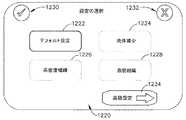
ユーザがスクリーン1200で生検設定ボタン1219をタップすると、タッチスクリーン410は、図39に示すスクリーン1220に遷移する。スクリーン1220は、ユーザが生検システム2の4つの互いに異なる予め決定された動作設定1222,1224,1226,1228の中から選択できるようにする。各々の所定の動作設定1222,1224,1226,1228は、一般的な臨床条件に対応する特定の生検システム2設定を含む。このような設定は、真空持続時間、適用された食塩水量(使用される場合)及び/又はカッタ150が針110内で前進する速度に対する設定を含むことができる。例えば、ユーザは一般的な目的のために好ましい場合がある予め決定された設定に生検システム2を設定するためにデフォルト設定ボタン1222をタップすることができる。同様に、ユーザは生検装置100の使用内に生検位置に伝達される食塩水のような流体の量を最小化しようとする時、好ましい場合がある所定の設定に生検システム2を設定するために流体減少ボタン1224をタップすることができる。高密度組織ボタン1226は、生検装置2が相対的により高密度の組職を生検するために使用される手順に好ましい場合がある予め決定された設定に生検システム2を設定するようにユーザによってタップされることができる。最後に、脂肪組織ボタン1228は、ユーザによってタップされて生検過程中により低密度の脂肪組織が遭遇し得る手順に好ましい場合がある予め決定された設定に生検システム2を設定できる。When the user taps
一旦、ユーザが与えられた所定の動作設定1222,1224,1226,1228を選択すると、選択された設定に対する所定のボタン1222,1224,1226,1228の色を暗くしたり変更することによってユーザの選択が図示される。例えば、デフォルト設定ボタン1222は、図39で選択されると図示される。スクリーン1220は、確認ボタン1230及び取り消しボタン1232をさらに含む。所定の選択的動作設定1222,1224,1226,1228をタップすると、ユーザは選択を格納しサンプルスクリーン1200に戻るために確認ボタン1230をタップすることができる。代案的には、ユーザは、選択された設定1222,1224,1226,1228を格納又は選択することなくサンプルスクリーン1200へ戻るためにいつでも取り消しボタン1232を押すことができる。 Once the user has selected a given
ユーザが生検システム2設定に対する追加制御を望む場合、ユーザは高級設定ボタン1234をタップすることができる。ユーザが高級設定ボタン1234をタップすると、タッチスクリーン410は、図40に示すように、スクリーン1240に遷移する。スクリーン1240は、ユーザに生検システム2の特定設定に対するより多くの制御を提供するように構成される。特に、スクリーン1240は、真空持続時間調整領域1241、運送食塩水調整領域1242及びカッタ速度調整領域1243を含む。各領域1241,1242,1243は、調整スライダ1244,1245,1246及びロック設定ボタン1247,1248,1249を含む。各々の調整スライダ1244,1245,1246は、一般にユーザが与えられた設定に対して予め決定された範囲を通って表示器をスライドすることによって与えられた設定を調整できるようにする。各ロック設定ボタン1247,1248,1249は、ユーザがパワーダウン/パワーアップサイクルが発生した後、生検システム2の後続使用のために選択された設定をメモリに格納するようにする。ロック設定ボタン1247,1248,1249が使用されない場合、与えられた設定は生検システム2の電源が切れるまで与えられた選択されたレベルで維持されることができる;又は与えられた設定が新しいレベルに調整される。If the user wants additional control over the
また、各領域1241,1242,1243は、与えられた設定が生検手順に対して実際にどのような影響を及ぼすかをグラフィックでユーザに知らせるグラフィック表現1250,1251,1253を含む。例えば、真空持続期間調整領域1241は、針110の側面開口114内に引っ張られる組織のグラフィック表現1250を含む。組織が側面開口に引っ張られるために真空が加えられる時間の量はユーザが調整スライダ1244の長さに沿ってその指を滑らせることによって調節されることができる。ユーザが調整スライダ1244を使用して設定を調整すると、ユーザはロック設定ボタン1247をタップして設定を格納することができる。 Each
運送食塩水調整領域1242は、食塩水を使用して針110を介して運搬された組織サンプルを示すグラフィック表現1251を含む。使用された食塩水の特定量は調整スライダ1245の長さに沿って指を滑らせることによってユーザによって調節されることができる。ユーザが調整スライダ1245を使用して設定を調整すると、ユーザはロック設定ボタン1248をタップして設定を格納することができる。Shipping
カッタ速度調整領域1243は、カッタ150の前進のための速度を示すグラフィック表現1252を含む。調整スライダ1246は、調整スライダ1246の長さに沿って指を滑らせて遅い速度、標準速度及び速い速度から選択を可能にできる。単なる例示として、遅い速度が選択された場合、カッタ150の前進の間にモータは低速が選択された場合、カッタ150の収縮中に約12000RPMで回転できる。モータは標準速度が選択された場合、カッタ150が前進する間に約20000RPMで回転し、標準速度が選択された場合、カッタ150が後退する間に約20000RPMで回転できる。モータ244は、速い速度が選択された場合、カッタ150の前進の間に約25000RPMで、速い速度が選択された場合、カッタ150の後退の間に約25000RPMで回転できる。もちろん、任意の他の適合した速度が用いられてもよい。ユーザは生検中の組織の性質及び/又は他の考慮事項に基づいてこれらの速度のうち1つを選択できる。ユーザが調整スライダ1246を使用して設定を調整すると、ユーザはロック設定ボタン1248をタップして設定を格納することができる。前記言及された速度値は任意の他の適切な速度が提供されることができるように単なる例にすぎないことを理解するべきである。 The cutter
もちろん、ここに記述された真空制御モジュール400の他の特徴と同様に、真空持続時間調整領域1241、運搬食塩水調整領域1242及びカッタ速度調整領域1243は所望する場合は省略できる。例えば、一部のバージョンは、以上で説明された多様な設定を単一設定で提供できる。Of course, like other features of the
また、図39を参照すると、スクリーン1220は、確認ボタン1254及び取り消しボタン1256をさらに含む。調整スライダ1244,1245,1246を使用して1つ以上の設定を調整すると、ユーザは確認ボタン1254をタップして選択を格納してサンプルスクリーン1200へ戻ることができる。代案的には、ユーザは、調整スライダ1244,1245,1246を使用して行われた任意の調整を格納せずサンプルスクリーン1200へ戻るためにいつでも取り消しボタン1256を押すことができる。ユーザが上述した予め決定された設定1222,1224,1226,1228を代わりに使用するために画面1208へ戻ることを望む場合、ユーザは調整スライダ1244,1245,1246を介して行われた任意の設定調整を格納することなくタッチスクリーン410をスクリーン1208に再度切り替えるようにする簡単な設定ボタン1258をタップしてそのようにすることができる。 Also, referring to FIG. 39, the
タッチスクリーン410を介したカッタ150の制御と関連づけられた前述した特徴は、単なる例示に過ぎないことを理解するべきである。必要に応じて修正、代替、補充又は省略できることを意味する。タッチスクリーン410を介してカッタ150の制御を提供するために用いられ得る多様な他の特徴は本明細書の教示を考慮すれば当業者に明白するはずである。 It should be understood that the features described above associated with controlling the
2.例示的な組織サンプルホルダインタフェース特徴
図37に戻ると、スクリーン1200の組織サンプルホルダ制御領域1260は「マーカーモード」ボタン1262、「ビュー位置設定」ボタン1264、組織サンプルホルダ300のグラフィック表現及び「チャンバ7へ進む」ボタン1268を含む。「マーカーモード」ボタン1262は、通路313がカッタ150と整列されるように組織サンプルホルダアセンブリ300を前進させるためにユーザによってタップすることができる。組織サンプルホルダ組立体300がこのような位置に前進する時、ユーザは通路313及びカッタルーメン151を介してマーカー伝達装置を挿入できる。一部の例で、カッタ150は、カッタ150の遠位エッジ152が側面開口114の近位端部と遠位端部の間に位置するように開口設定ボタン1218を介して設定され、側面開口114が部分的にのみ開放されるようにする。この場合、特定マーカーは側面開口114の開口が減少されるため生検装置10と互換できない場合がある。したがって、「マーカーモード」ボタン1262は、ユーザに小型マーカーのみを使用したり側面開口114を完全に開けるように開口設定ボタン1218を介してカッタ150を調整することをユーザに想起させるための図41に示す「小型」表示器1263を含むことができる。2. Exemplary Tissue Sample Holder Interface Features Returning to FIG. 37, the tissue sample
「ビュー位置設定」ボタン1264は、ユーザが組織サンプルを取得する度に組織サンプルホルダ300のどの側が組織サンプルの提示のために指定されるかを選択できるようにする。特に、ユーザは、組織サンプル提示のための4つの位置、すなわち12時方向位置、3時方向位置、6時方向位置及び9時方向位置を選択できる。図42から理解できるように、ユーザが「ビュー位置設定」ボタン1264をタップすると、グラフィック表現1266が完全に照明されたままの間スクリーン1200はほの暗くなったり非活性状態を示すことができる。また、選択ボタン1265が現れてもよい。組織サンプル提示のための与えられた位置を選択するために、ユーザは与えられた時計回り位置に対応する与えられた選択ボタン1265を選択できる。これらの位置は組織サンプルホルダ300の中心軸に対する角度位置に対応する。もちろん、任意の他の適切な位置オプションが提供されてもよい。ユーザは生検装置10に対するユーザの物理的位置、隣接する装置の位置などのような考慮事項に基づいて、切断された組織サンプルの最上の可視性をユーザに提供するための位置を選択できる。ユーザが「ビュー位置設定」ボタン1264を使用して提示位置を積極的に選択しない場合は、12時方向位置のようない以上で羅列された位置(又はある他の位置)のうち1つをデフォルトに自動的に選択されることができることを理解するべきである。組織サンプル提示に対するさらに詳細な内容は、以下でより詳細に説明される。組織サンプル提示の例に関する追加的な細部事項は、本明細書に参照として引用された米国出願公開番号第2008/0214955号に記載されている。 The "set view position"
生検装置10の作動中に、図37に示すスクリーン1200の組織サンプルホルダ制御領域1260は、組織サンプルホルダ300のグラフィック表現1266で各チャンバ346を連続的に満たすことを示す。特に、図43は、グラフィック表現1266で残りのチャンバを照明するために用いられたカラーと他のカラーでグラフィック表現1266にこれらの初めて6つのチャンバを照明することによって、最初の6つのチャンバ346がフルであることを図示する。したがって、各々の組織サンプルが収集される時、グラフィック表現1266のチャンバは組織サンプルホルダ組立体300の充電を示すために連続的に色を変化させる。「チャンバ7へ進む」ボタン1268が使用される場合、組織サンプルホルダアセンブリ300は初めて6つのチャンバ346をスキップできる。「チャンバ7へ進む」がタップされると、その省略されたチャンバ346はグラフィック表現1266の他のカラーで照明されることができる。すなわち、グラフィック表現1266は、1つのカラーで利用可能なチャンバ、他のカラーで占有されたチャンバ及びさらに他のカラーで省略されたチャンバを表すことができる。 During operation of
上述のように、一部の例で、ユーザは組織サンプルホルダアセンブリ300内のチャンバ346をスキップしようとすることができる。そのために、ユーザは1つの動作で6つのチャンバ346に対応する増加でマニフォールド310を回転させるために「チャンバ7へ進む」ボタン1268をタップすることができる。換言すれば、「チャンバ7へ進む」ボタン1268をタップすると、どのチャンバ346がカッタ150のルーメン151と予め整列されたかにかかわらず、マニフォールド310がカッタ150のルーメン151に組織サンプルホルダ組立体300の第7チャンバ346をインデクシングさせる。このような特徴は、ユーザが6つ未満の組織サンプルが得られた生検手順の中間にマニフォールド310から第1トレー330(第1の6つのチャンバ346を提供)を除去した場合に好ましい場合があり;ユーザは(第2トレー330の第1チャンバ346になる)第7チャンバ346から開始する生検手順を続けることを望む。一部のバージョンでは「チャンバ7へ進む」ボタン1268をタップすると、自動的にマニフォールド310が漸進的に回転して6つではなく単一チャンバ346をスキップするように増加される。例えば、これは第1組織サンプルが5時方向位置などでチャンバ346に沈殿された場合に好ましい場合がある。 As mentioned above, in some examples, the user may attempt to skip
また、ユーザがプローブ100から組織サンプルホルダ300を除去して組織サンプルを追加的に獲得するために新しい組織サンプルホルダ300をプローブ100と結合しようとする生検手順の間(例えば、針が依然として患者の乳房に挿入される)に発生し得る。ユーザがこれを遂行する時、ユーザは図43に示すように「チャンバリセット」ボタン1270をタップすることができる。「チャンバリセット」ボタン1270は、「チャンバ7へ進む」ボタン1268がタップされた後、スクリーン1200上に表面化する。本例で、「チャンバリセット」ボタン1270は、「チャンバ7へ進む」ボタン1268を代替するように図示される。他のバージョンでは「チャンバリセット」ボタン1270が別途現れてもよい。ユーザが「チャンバリセット」ボタン1270をタップすると、真空制御モジュール400は全てのチャンバ346が空いていることを表すために組織サンプルホルダ300のグラフィック表現1266を再設定する。 Also, during a biopsy procedure in which a user removes the
タッチスクリーン410を介した組織サンプルホルダ300の制御と関連づけられた前述した特徴は単なる例示的なものであることを理解するべきである;必要に応じて修正、代替、補充又は省略できることを意味する。タッチスクリーン410を介して組織サンプルホルダ300の制御を提供するために用いられ得る多様な他の特徴は本明細書の教示を考慮すれば当業者に明白であろう。 It should be understood that the above-mentioned features associated with the control of the
3.例示的な真空インタフェース特徴
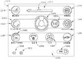
依然として図37を参照すると、スクリーン1200の真空制御領域1280は、「真空レベル設定」ボタン1282、「クリーンカップ」ボタン1284及び「正常真空」ボタン1286を含む。ユーザが「真空レベル設定」ボタン1282をタップすると、スクリーン1200は図44に示すように暗くなり、その結果、領域1210,1260は暗く、ボタン1284,1286も暗い。また、一般に左側から右側へ長さが増加するバーセット1288が現れる。ボタン1282はユーザが真空ポンプによって提供される真空の量を選択できるようにする。特に、ユーザは真空レベルを選択するためにバーセット1288の特定バーをタップすることができる。代案的には、ユーザは所望の真空レベルに到達するまで自らの指をバー1288に沿ってスライドさせた後、タッチスクリーン410から指を離すことができる。特定真空レベルは左側から右側へバー1288の長さが増加するとともにグラフィックで表示される。すなわち、ユーザが右にバーを選択するほど真空水準が高くなる。所望の真空レベルが選択されると、ユーザは「真空レベル設定」ボタン1282をタップして図37に示すスクリーン1200に戻すことができる。図37に示すように、「真空レベル設定」ボタン1282は「真空レベル設定」ボタン1282に統合されたバーセット1283によって選択された真空レベルを持続的にディスプレイする。3. Exemplary Vacuum Interface Features Still referring to FIG. 37, the
また、図37を参照すると、ユーザは組織サンプルホルダ組立体300内に含まれた任意の組織のクリーニングを開始するために「クリーンカップ」ボタン1284を選択できる。例えば、ユーザが「クリーンカップ」ボタン1284をタップする場合、生検システム2は組織サンプルホルダ組立体300に食塩水を自動的に伝達できる。次に、生検システム2は組織サンプルホルダ組立体300で真空を開始して食塩水を任意の組織サンプルを介して、そして、組織サンプルホルダ組立体300の外に引き出すことができる。このような食塩水及び真空の組み合わせは組織サンプルから血液及び/又は他の破片を效果的にフラッシュすることができるので組織サンプルの視角化を容易にする。一部の実施形態で、「クリーンカップ」ボタン1284は、2つのボタンに分離され、他のボタンが組織サンプルホルダアセンブリ300で真空を開始するように構成される間に1つのボタンが組織サンプル組織内の真空を開始するように、他のボタンが構成される間に1つのボタンが組織サンプルホルダ組立体300に食塩水を伝達するように構成されることができる。もちろん、本明細書に説明された他の特徴と同様に、所望する場合は「クリーンカップ」ボタン1284が省略されてもよい。Also referring to FIG. 37, the user can select the “clean cup”
ユーザは「正常真空」サイクルを開始するために「正常真空」ボタン1286をタップすることができる。ユーザは次いで「正常真空」サイクルを停止させるためにボタン1286を再度押すことができる。追加的に又は代案的には、ユーザが生検装置10を作動させて組織サンプルを抽出したり他のユーザ入力を提供する時、「正常真空」サイクルが自動的に中断できる。「正常真空」サイクルは、生検部位で持続的な吸入を提供することが好ましい場合がある場合に用いられ得る。例えば、若干の生検サンプルを得た後、ユーザは内部の組織サンプルを検査するためにマニフォールド310からトレー330を抽出することを望む場合がある。ユーザはこの時間の間、特にユーザがより多くの生検サンプルを得ようとする場合、患者の乳房に針110を挿入されたまま置くことを望む場合がある。したがって、生検装置10は、この時間の間実質的にアイドル状態にある。このアイドル時間の間に生検装置10内で一種の空気流れを提供することが好ましい場合がある。単なる例として、吸入が血液を持っていけるように生検部位が顕著に出血する場合には、生検部位で吸入を提供することが好ましい場合がある。追加的に又は代案的には、生検装置10を介した空気流れを維持することは、プローブ100の特定内部構成要素で血液及び/又は他の体液が凝固する可能性を減少させることができる;及び/又は生検部位で血腫形成の可能性を減少させることができる。 The user can tap the "normal vacuum"
タッチスクリーン410を介した真空制御と関連づけられた前述した特徴は単なる例示に過ぎないことを理解するべきである。必要に応じて修正、代替、補充又は省略できることを意味する。タッチスクリーン410を介した真空制御を提供するために用いられ得る多様な他の特徴は本明細書の教示を考慮すれば当業者に明白であろう。同様に、タッチスクリーン410を介して制御できるシステム2の多様な他の特徴、及びそのような特徴がタッチスクリーン410を介して制御できる方法は本明細書の教示の観点から当業者に明白であろう。 It should be understood that the above-described features associated with vacuum control via
4.例示的な待機モード
前述のように、サンプル画面1200は待機ボタン1202を含む。待機ボタン1202は、ユーザが待機モデルを入力するためにタップされることができる。特に、待機ボタン1202がタップされる時、タッチスクリーン410はスクリーン1290に遷移して待機モードに入る。図45から理解できるように、スクリーン1290はサンプルスクリーン1200がタッチスクリーン410によってディスプレイされる生体システム2の活性モードに戻ることを許可するバックボタン1292を除けば実質的にスクリーン1060に類似している。他のスクリーンは、さらに、待機ボタン1202を含むことができることを理解するべきである;又は待機ボタン1202は簡単に省略されてもよい。4. Exemplary Standby Mode As described above, the
5.「個別」モードでの生検システムの例示的な動作
図46は、前述した制御モジュール400の動作状態をフローチャート2000で図示する。フローチャート2000は図35に示すフローチャート1100の続きであることを理解するべきである。特に、フローチャート1100は、組織サンプルホルダ組立体300がプローブに付着される時、ブロック1114で終わるということを注目するべきである。上述のように、ブロック1114は、上述されたサンプルスクリーン1200に対応する。サンプルスクリーン1200は、ブロック1114で始まって図46のフローチャートでブロック1114で類似に表示される。サンプルスクリーン1200は、図46のフローチャートのブロック1114に類似しているように図示され、図16のフローチャートはブロック114で開始される。上述のように、スクリーン1200は、ユーザが進行できるいくつかの可能なオプションを提供する。例えば、ユーザは、ブロック2022によって表示されたように、開口設定ボタン1218をタップして側面開口114に対してカッタ150によって限定された開口を設定できる。この場合に、ボタン1215,1216,1217は、ブロック2050、2052、2054によって指示されたように、複数の互いに異なる開口設定の間で選択するために用いられることができる。所定の開口大きさが選択されると、ユーザはブロック1114に表示されたように、サンプルスクリーン1200へ戻ることができる。5. Exemplary Operation of Biopsy System in "Individual" Mode FIG. 46 illustrates in a
ユーザは、ブロック2024,2056によって指示されたように、生検設定ボタン1219を押すことによって生検設定画面1220に入ることができる。一旦、タッチスクリーン410がブロック2056に表示されたように、スクリーン1220に切り替えられると、ユーザは、ブロック2060,2062,2064,2066によって指示されたように、予め決定された設定1222,1224,1226,1228を選択できる。代案的には、ユーザは、ブロック2070によって指示されたように、高級生検設定を調整するためにスクリーン1240に入ることを選択できる。上述のように、ユーザは、ブロック2080,2082,2084によって指示されたように、調整スライダ1244,1245,1246を使用して真空持続時間、運送食塩水及びカッタ速度を選択的に調整することができる。どのスクリーン1220,1240がユーザによって使用されるかにかかわらず、ユーザは、一旦、設定に対する任意の変更が行われると、ブロック1114によって指示されたように、サンプルスクリーン1200へ戻ることができる。The user can enter
ユーザは、ブロック2028に表示されたように、「マーカーモード」ボタン1262を押してマーカーモードを開始することができる。「小型」表示器1263の照明はブロック2044によって表示される。「小型(petite)」表示器1263が照明されるか否かにかかわらず、上述のように、生検システム2がマーカーモードにある時、サンプルスクリーン1200がディスプレイされたまま維持される。 The user may press the “marker mode”
サンプルスクリーン1200から、ユーザは、ブロック2026によって表示されたように「ビュー位置設定」ボタン1264を押すこともできる。理解できるように、「ビュー位置設定」ボタン1264が押されると、タッチスクリーン410は、サンプルスクリーン1200を継続してディスプレイする。しかし、上述のように、組織サンプルホルダアセンブリ300のグラフィック表現1266は(例えば、ほの暗かったり暗くなるサンプルスクリーン1200の他の特徴によって)残りのサンプルスクリーン1200に比べて強調されることができる。選択ボタン1265は、さらに、ユーザが上述のように所望のビュー位置を選択できるように現れることができる。 From the
ユーザは、さらに、ブロック2032によって表示されたように、サンプルスクリーン1200から「チャンバ7へ進む」ボタン1268を押すことができる。以上で説明したように、「チャンバ7へ進む」ボタン1268を押すと、組織サンプルホルダアセンブリ300が第7チャンバ346へ進むようになる。ブロック2046は、前述のように、「チャンバ7へ進む」ボタン1268が押された後に「チャンバリセット」ボタン1270が現れ、ユーザがグラフィック表現1266を再設定できるようにする。 The user may also press the “go to
ユーザは、さらに、ブロック2030によって表示されたように、「真空レベル設定」ボタン1282を押すことによってサンプルスクリーン1200から生検システム2の真空レベルを設定できる。上述のように、「真空レベル設定」ボタン1282が押されると、サンプルスクリーン1200はタッチスクリーン410上に維持されるが、真空レベルの調整を許容する1セットのバー1288を強調するために多様な特徴が暗くなったりほの暗くなる。所望の真空レベルが設定されると、ユーザは「真空レベル設定」ボタン1282を再度押して残りのサンプルスクリーン2010を再度活性化できる。 The user can also set the vacuum level of
ブロック2020は、2つの真空モードがサンプルスクリーン1200から活性化されることができることを表す。例えば、ブロック2040は、前述した組織サンプルホルダアセンブリ300に食塩水及び真空を提供する手順を活性化するために「クリーンカップ」ボタン1284が押されたことを表す。ブロック2042は、正常真空モードが「正常真空」ボタン1286を押すことによって活性化されることができることを表す。「クリーンカップ」ボタン1284又は「正常真空」ボタン1286が押されたか否かにかかわらず、2つの場合はいずれもサンプルスクリーンはタッチスクリーン410上に見られる。
もちろん、前述した動作順序は単なる例示的な例に過ぎない。多様な他の動作順序が前述したこと以外にも又は代わりに提供され得る。他の適切な動作順序は本明細書の教示を考慮すれば当業者に明白であろう。 Of course, the operation sequence described above is merely an example. Various other operational sequences may be provided in addition to or in the alternative. Other suitable sequences of operations will be apparent to those of ordinary skill in the art in view of the teachings herein.
C.3つのトレー組織サンプルホルダのための例示的なサンプルスクリーン
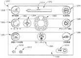
図47は、前述のように画面1080を図示する。以上で説明したように、画面1080は初期化以前に表示される。このステップで、バルクトレー選択ボタン1032を介してバルクサンプリングモードが選択されて組織サンプルホルダ700が生検装置100とともに使用される。初期化を開始するために、ユーザはメニュー進行ボタン1036を押すことができる。初期化が開始されると、タッチスクリーン410は、図48に示すように、サンプルスクリーン2200に自動的に遷移する。サンプルスクリーン2200は、プローブ100が組織サンプルホルダアセンブリ700を具備する時、プローブ100を制御するように構成される。サンプルスクリーン2200は、本願で別に言及されない限り、上述したサンプルスクリーン1200と実質的に同じことを理解するべきである。C. Exemplary Sample Screens for Three Tray Tissue Sample Holders FIG. 47 illustrates
サンプルスクリーン2200は、カッタ制御領域2210、組織サンプルホルダ制御領域2260及び真空制御領域2280を含む。一般に、領域2210,2260,2280は、前述した領域1210,1260,1280に類似している。生検システム2の各機能がこの例で特定の方式で編成されているが、代案的な組織図が他の例で用いられ得ることを理解するべきである。サンプルスクリーン2200は、さらに、音量調整ボタン1008、明るさ調整ボタン1010及び待機ボタン2202を含む。待機ボタン2202は、一般に生検システム2を待機モードに位置させるように動作可能に構成されてタッチスクリーン410が待機スクリーン2290に切り替えられるようにする。 The
1.例示的なカッタインタフェース特徴
図48に示すように、スクリーン2200のカッタ制御領域2210は、針110の遠位端部のグラフィック表現2212、カッタ150のグラフィック表現2214、「開口設定」ボタン2218及び生検設定ボタン2219を含む。1. Exemplary Cutter Interface Features As shown in FIG. 48, the
ユーザが「開口設定」ボタン2218をタップすると、タッチスクリーン410は、図49に示すスクリーン2208に遷移する。スクリーン2208は、領域2260,2280が暗く、ボタン2219が暗くて追加ボタン2215,2216,2217が針110の遠位端部のグラフィック表現2212に重なって現れることを除けばスクリーン2200に類似している。ボタン2215,2216,2217は、ユーザが生検装置10の作動中にカッタ150の遠位エッジ152に対して最も近位の位置を設定できるようにする。特に、ボタン2215は、生検装置10の作動中にカッタ150の遠位エッジ152に最も近い位置を設定し、カッタ150が遠位方向に進行する前に側面開口114はカッタ150によってのみ12mm開放されるようにする。ボタン2216は、生検装置10の作動中にカッタ150の遠位エッジ152に対して最も近位の位置を設定し、この時、側面開口114はカッタ150が遠位方向に進行する前にカッタ150によって18mmのみ開く。ボタン2217は、生検装置10の作動中にカッタ150の遠位エッジ152に対して最も近位の位置を設定し、この時、カッタ150が遠位方向に進行する前にカッタ150によって側面開口114が完全に開放される。もちろん、このような増加は、単なる例示にすぎず、任意の他の適切な増加が用いられてもよい。本例で、生検システム2はユーザがスクリーン2208を介して互いに異なる開口大きさを選択しない場合に完全に開放された開口114設定をデフォルトとするであろう。 When the user taps the “open aperture setting”
ユーザが特定ボタン2215,2216,2217をタップすると、スクリーン2208はグラフィック表現2214の遠位端部がユーザによって丁度選択された位置と一致するようにカッタ150のグラフィック表現2214の位置を変更することによってフィードバックを提供する。グラフィック表現2214のこのような位置指定は位置指定が後でユーザによって変更されるまで続けることができる。例えば、図49は、生検装置10の使用中の18mm位置のグラフィック表現2214を図示する。 When the user taps a
単なる例として、システム2は、2009年4月14日に発行された「可変側面開口を有する生検装置」という名称の米国特許第7,517,322号(この開示内容は本願に参照として含まれる)の教示のうち少なくとも一部に従って;及び/又は米国出願公開番号第2008/0214955号の教示のうち少なくとも一部に従って前述した「可変開口」機能を提供できる。一部のバージョンで、前述したカッタ150のグラフィック表現2214は、第1カラーで提供され;カッタ150の第2グラフィック表現は第2カラーで提供される。この2番目のグラフィック表現はカッタの実際位置をリアルタイムで表す。 By way of example only,
また、図48を参照すると、ユーザが生検設定ボタン2219をタップすると、タッチスクリーン410は、図50に示すスクリーン2220に遷移する。スクリーン2220は、ユーザが生検システム2の4つの互いに異なる予め決定された動作設定2222,2224,2226,2228の中から選択できるようにする。予め決定された各々の動作設定2222,2224,2226,2228は前述した予め決定された動作設定1222,1224,1226,1228と実質的に同じで、各々の所定動作設定2222,2224,2226,2228はここで繰り返さない。一旦、ユーザが与えられた所定動作設定2222,2224,2226,2228を選択すると、選択された設定に対する所定のボタン2222,2224,2226,2228の色を暗くしたり変更することによってユーザ選択が図示される。例えば、デフォルト設定ボタン2222は、図50で選択されると図示される。スクリーン2220は、確認ボタン2230及び取り消しボタン2232をさらに含む。与えられた予め決定された動作設定2222,2224,2226,2228をタップすることに応じて、ユーザは選択を格納してサンプルスクリーン2200へ戻るために確認ボタン2230をタップすることができる。代案として、ユーザは選択を行なわず又は選択された設定2222,2224,2226,2228を格納することなくサンプルスクリーン2200へ戻るためにいつでも取り消しボタン2232をタップすることができる。 Further, referring to FIG. 48, when the user taps
ユーザが生検システム2設定に対する追加制御を望む場合、ユーザは高級設定ボタン2234を押すことができる。ユーザが高級設定ボタン2234をタップすると、タッチスクリーン410は、図51に示すようにスクリーン2240に遷移する。スクリーン2240は、前述したスクリーン1240に類似している。特に、スクリーン2240は、真空持続時間調整領域2241、運送食塩水調整領域2242及びカッタ速度調整領域2243を含む。しかし、スクリーン1240と異なって、スクリーン2240は、以下でより詳細に説明される自動進入限界調整機能部2257をさらに含む。If the user desires additional control over the
各領域2241,2242,2243は、調整スライダ2244,2245,2246及びロック設定ボタン2247,2248,2249を含む。調整スライダ2244,2245,2246及びロック設定ボタン2247,2248,2249は、調整スライダ1244,1245,1246及びロック設定ボタン1247,1248,1249と実質的に同じで、このような特徴に対する詳細な説明はここで繰り返さない。また、各領域2241,2242,2243は、前述したグラフィック表現1250,1251,1253と実質的に類似しているグラフィック表現2250,2251,2253を含み、このような特徴に対する詳細な説明はここで繰り返さない。 Each
上述のように、スクリーン2240は、自動進入限界調整機能部2257をさらに含む。用語「自動進入限界」は、様々な組織サンプルを収集するために組織サンプルホルダアセンブリ700とともに使用される機能を示す。一般に、本明細書の他の所で言及されたように、各々の組織サンプルチャンバ746は、複数の組織サンプルを収容するように構成される。したがって、与えられたチャンバ746は、所定数の組織サンプル獲得サイクルの間、カッタ150でインデクシングされたまま維持されることができる。所定数の組織獲得サイクルに到達すると、組織サンプルホルダ組立体は、次のチャンバ746で進むことができる。したがって、自動進入限界調整機能部2257は、組織サンプルホルダ組立体がカッタ150で次のチャンバ746をインデクシングする時を決定する時に使用される所定数の組織獲得サイクルを調整するために用いられ得る。ロック設定ボタン2259は、さらに、自動進入限界調整機能部2257と関して後で設定のためにメモリに設定を格納することができる。 As described above, the
もちろん、ここに記述された真空制御モジュール400の他の特徴と同様に、真空持続時間調整領域2241、運送食塩水調整領域2242、カッタ速度調整領域2243及び自動進入限界調整機能部2257は所望の場合は省略されてもよい。例えば、一部のバージョンは、以上で説明された多様な設定を単一設定で提供できる。Of course, like the other features of the
スクリーン2220は、確認ボタン2254及び取り消しボタン2256をさらに含む。調整スライダ2244,2245,2246及び/又は自動進入限界調整機能部2257を使用して1つ以上の設定を調整する時、ユーザは確認ボタン2254をタップして選択事項を格納してサンプル画面2200へ戻ることができる。代案的には、ユーザは調整スライダ2244,2245,2246及び/又は自動進入限界調整機能部を使用して行われた任意の調整を格納することなくサンプルスクリーン2200へ戻るためにいつでも取り消しボタン2256をタップすることができる。ユーザが以上で説明された所定の設定2222,2224,2226,2228を使用する代わりにスクリーン2208へ戻ることを望む場合、ユーザは、簡単設定ボタン2258を軽くタッチすることによって調整スライダ2244,2245,2246及び自動進入限界調整機能部2257を介して設定された設定を格納することなくタッチスクリーン410がスクリーン1208に再度切り替えるようにすることができる。 The
タッチスクリーン410を介したカッタ150の制御と関連づけられた前述した特徴は、単なる例示に過ぎないということを理解するべきである。必要に応じて、修正、代替、補充又は省略できることを意味する。タッチスクリーン410を介してカッタ150の制御を提供するために用いられ得る多様な他の特徴は本明細書の教示を考慮すれば当業者に明白であろう。 It should be appreciated that the features described above associated with controlling the
2.例示的な組織サンプルホルダインタフェース特徴
また、図48に示すように、スクリーン2200の組織サンプルホルダ制御領域2260は、「マーカーモード」ボタン2262、「自動進入」ボタン2264、組織サンプルホルダ300のグラフィック表現2266及び「ニューカップ」ボタン2268を含む。「マーカーモード」ボタン2262は、通路713がカッタ150と整列されるように組織サンプルホルダアセンブリ700を前進させるためにユーザによってタップされることができる。組織サンプルホルダ組立体700がこのような位置に前進する時、ユーザは通路713及びカッタルーメン151を介してマーカー伝達装置を挿入してマーカーを針110を介して生検サイトに伝達できる。一部の例で、カッタ150は、カッタ150の遠位エッジ152が側面開口114の近位端部と遠位端部の間に位置するように開口設定ボタン1218を介して設定されることができ、この時、側面開口114は単に部分的に開放されている。この場合、特定マーカーは、側面開口114の開口が減少されるため生検装置10と互換できない場合がある。したがって、「マーカーモード」ボタン2262は、図52に示すように、小型マーカーだけを使用したり側面開口114を完全に開けるように設定された開口ボタン2218を介してカッタ150を調整するようにユーザに想起させる「小型(petite)」表示器2263を含むことができる。2. Exemplary Tissue Sample Holder Interface Features Also, as shown in FIG. 48, the tissue sample
「自動進入」ボタン2264は、ユーザが自動進入モードを選択できるようにする。上述のように、自動進入モードは、組織サンプルホルダ組立体700が次のチャンバ746でインデクシングされる前に予め決定された数の組織サンプルが組織サンプルホルダ組立体700の単一チャンバ746に収集されるようにする。このような特徴は大量の組織を除去しなければならない手順に好ましい場合がある。自動進入モードが非活性の場合、組織サンプルアセンブリ700は、組織ホルダアセンブリ300に対して前述のように漸進的に前進できる。「自動進入」ボタン2264がユーザによって押されると、「自動進入」ボタン2264が点灯する。また、前進する前に行われる組織サンプル収集サイクルの特定数は「自動進入」ボタン2264に直接ディスプレイされることができる。上述のように、組織サンプル収集サイクルの特定数は、ユーザが生検設定ボタン2219を介して高級生検設定に入ることによって調整されることができる。 The "automatic entry" button 2264 allows the user to select the automatic entry mode. As described above, the automatic approach mode is such that a predetermined number of tissue samples are collected in a
特定チャンバ746が所望のレベルを満たしか、全てのチャンバ746が所望のレベルで満たされると、ユーザは組織サンプルホルダアセンブリ700から1つ以上の組織収容トレー730を除去できる。グラフィック表現2266を再設定するために、ユーザは「ニューカップ」ボタン2268をタップすることができる。一旦、グラフィック表現2266が再設定されると、ユーザは新しい組織収容トレー730を使用して追加的な組織サンプルの採取を開始することができる。 Once the
タッチスクリーン410を介した組織サンプルホルダ300の制御と関連づけられた前述した特徴は単なる例示的なものであることを理解するべきである;必要に応じて修正、代替、補充又は省略できることを意味する。タッチスクリーン410を介して組織サンプルホルダ300の制御を提供するために用いられ得る多様な他の特徴は本明細書の教示を考慮すれば当業者に明白であろう。 It should be understood that the above-mentioned features associated with the control of the
3.例示的な真空インタフェース特徴
依然として図48を参照すると、スクリーン2200の真空制御領域2280は、「真空レベル設定」ボタン2282、「排水」ボタン2284、「リンス」ボタン2285、及び「正常真空」ボタン2286を含む。一般に、「真空レベル設定」ボタン2282及び「正常真空」ボタン2286は、前述した「真空レベル設定」ボタン1282及び「正常真空」ボタン1286と実質的に同じであるため、「真空レベル設定」ボタン2282と「正常真空」ボタン2286は、ここで繰り返して説明されない。3. Exemplary Vacuum Interface Features Still referring to FIG. 48, the
しかし、スクリーン1200と異なって、スクリーン2200は、「クリーンカップ」ボタン1284と関連して上述したように、クリーンカップモードのための別途のボタン2284、2285を含む。特に、ユーザはまず「排水」ボタン2284をタップしてクリーンカップモードに関与することができる。「排水」ボタン2284をタップすると、食塩水及び/又は体液のような過剰流体がチャンバ746から除去されることができる。「リンス(Rinse)」ボタン2285は、次いで食塩水を組織サンプルホルダアセンブリ700のチャンバ746に提供するようにタップされることができ、チャンバ746内に含まれた任意の組織サンプルを灌漑する。チャンバ746へ伝達された食塩水は再度「排水」ボタン2284をタップして除去できる。もちろん、前記手順は単なる例示的なものであり、他の例で、ボタン2284,2285は所望の通り任意の順序で用いられる、又は全く用いられない場合もある。However, unlike the
タッチスクリーン410を介した真空制御と関連づけられた前述した特徴は単なる例示に過ぎないことを理解するべきである。必要に応じて、修正、代替、補充又は省略できることを意味する。タッチスクリーン410を介した真空制御を提供するために用いられ得る多様な他の特徴は本明細書の教示を考慮すれば当業者に明白であろう。同様に、タッチスクリーン410を介して制御できるシステム2の多様な他の特徴、及びそのような特徴がタッチスクリーン410を介して制御できる方法は、本技術分野の当業者に明白であろう。 It should be understood that the above-described features associated with vacuum control via
4.例示的な待機モード
上述のように、サンプルスクリーン2200は、待機ボタン2202を含む。待機ボタン2202は、ユーザが待機モデルを入力するためにタップされることができる。特に、待機ボタン2202がタップされる時、タッチスクリーン410は、スクリーン2290へ移動して待機モードに入る。図53から理解できるように、スクリーン2290は、サンプルスクリーン2200がタッチスクリーン410によってディスプレイされる生検システム2の活性モードに戻ることを許すバックボタン2292を除けばスクリーン2290は、前述したスクリーン1080と実質的に類似している。他のスクリーンは、さらに、待機ボタン2202を含むことができるということを理解するべきである;又は待機ボタン2202は簡単に省略できる。4. Exemplary Standby Mode As described above, the
5.「バルク(bulk)」モードでの生検システムの例示的な動作
図54は、前述した制御モジュール400の動作状態をフローチャート2400で図示する。フローチャート2400は、図35に示すフローチャート1100の続きである。特に、フローチャート1100は、組織サンプルホルダアセンブリ700がプローブ100に付着される時、ブロック1130で終わる。上述のように、ブロック1130は、上述したサンプルスクリーン2200に対応する。サンプルスクリーン2200は、ブロック1130で始まるフローチャート2000を有する図54のブロック1130によって類似に表示される。上述のように、スクリーン2200は、ユーザが続行できるいくつかの可能なオプションを提供する。例えば、ユーザは、ブロック2422によって表示されたように開口設定ボタン2218をタップすることによって側面開口114に対してカッタ150によって限定された開口を設定できる。この場合に、ボタン2215,2216,2217は、ブロック2450,2452,2454によって指示されたように、複数の互いに異なる開口設定の間で選択するために用いられてもよい。所定の開口大きさが選択されると、ユーザはブロック1130に表示されたように、サンプルスクリーン2200へ戻ることができる。5. Exemplary Operation of Biopsy System in “Bulk” Mode FIG. 54 illustrates in a
ユーザは、ブロック2424,2456によって指示されたように、生検設定ボタン2219を押すことによって生検設定画面2220に入ることができる。ブロック2456によって表示されたように、タッチスクリーン410がスクリーン2220に切り替えられると、ユーザはブロック2460,2462,2464,2466によって指示されたように、予め決定された設定2222,2224,2226,2228を選択できる。代案的には、ユーザはブロック2470によって指示されたように、高級生検設定を調整するためにスクリーン2240に入ることを選択できる。上述のように、ユーザはブロック2480,2482によって指示されたように、調整スライダ1244,1245,1246及び自動進入限界調整機能部2257を使用する自動進入限界を使用してブロック2480,2482,2484,2486で表示される真空持続時間、運送食塩水及びカッタ速度を選択的に調整することができる。どのスクリーン2220,2240がユーザによって使用されるかにかかわらず、ユーザは、一旦、設定に対する任意の変更が行われると、ブロック1130によって指示されたように、サンプルスクリーン2200へ戻ることができる。The user can enter biopsy settings screen 2220 by pressing
ユーザは、ブロック2428によって表示されたように「マーカーモード」ボタン2262を押すことによってマーカーモードを開始できる。「小型」表示器2263の照明はブロック2446によって表示される。「小型(petite)」表示器2263が点灯するか否かにかかわらず、以上で説明したように、生検装置2がマーカーモードにある時、サンプルスクリーン2200が表示されている。 The user may enter marker mode by pressing the "marker mode"
ユーザは、さらに、ブロック2430に表示されたように、「真空レベル設定」ボタン2282を押すことによってサンプルスクリーン2200から生検システム2の真空レベルを設定できる。上述のように、「真空レベル設定」ボタン2282が押されると、サンプルスクリーン2200はタッチスクリーン410上に維持されるが、真空レベルの調整を許容するバーセット2288を強調するために多様な機能が暗く又はほの暗く表示される。所望の真空レベルが設定されると、ユーザは「真空レベル設定」ボタン2282を再度押して残りのサンプルスクリーン2200を再度活性化できる。 The user can also set the vacuum level of
ブロック2420は、3つの真空モードがサンプルスクリーン2200から活性化されることができることを表す。例えば、ブロック2440は、前述した組織サンプルホルダアセンブリ700に真空を提供する手順を活性化するために「排水」ボタン2284が押されることができることを表す。ブロック2442は、前述した組織サンプルホルダアセンブリ700に食塩水を提供する手順を活性化するために「リンス」ボタン2285が押されることができることを表す。ブロック2444は、「正常真空」ボタン2286を押して正常真空モードが活性化されることができることを表す。「排水」ボタン1284、「リンス」ボタン2285又は「正常真空」ボタン1286が押されたか否かにかかわらず、2つの場合はいずれもサンプルスクリーンはタッチスクリーン410上に見られる。
V.例示的な組み合わせ
下記実施例は、本明細書の教示が結合されるか、又は適用されることができる多様な非−包括的な方法に関する。次の例は本出願又は本出願の後続出願にいつでも提示されることができる請求項の適用範囲を制限するためのものではないことを理解するべきである。兔責条項はない。次の例は単なる例示的な目的のためにのみ提供される。本明細書の多様な教示が多数の他の方式で配列されて適用されることができるということが考慮される。また、いくつかの変形例は以下の例で言及された特定特徴を省略することもできる。したがって、発明者又は発明者が関心を持つ継承者によって今後明示的に明示されない限り、以下に言及された特徴又は特徴のうちいかなるものも重要と見なされるべきではない。この申請書又はこの申請書と関連づけられた後続資料に以下に言及されたこと以外の追加機能を含む請求がある場合、その追加機能は特許可能性と関連して追加されたものとみなされない。V. Illustrative Combinations The following examples relate to various non-comprehensive ways in which the teachings herein may be combined or applied. It should be understood that the following examples are not intended to limit the scope of the claims, which may be presented at any time in this application or any subsequent application of this application. There is no liability clause. The following example is provided for illustrative purposes only. It is contemplated that the various teachings herein may be arranged and applied in numerous other ways. In addition, some modifications may omit the specific features mentioned in the following examples. Therefore, none of the features or characteristics mentioned below should be considered significant unless explicitly stated hereafter by the inventor or a successor of interest to the inventor. If this application or any subsequent material associated with this application claims to include additional features other than those mentioned below, such additional features are not considered to have been added in connection with patentability.
実施例1
生検システムは、(a)複数のプローブを含むプローブセット、前記プローブセットの各々のプローブは(i)プローブ本体、(ii)針、(iii)カッタ、及び(iv)1つ以上の組織サンプルを収容するために前記カッタと連通する組織サンプルホルダを含み;(b)ホルスタ(holster)、前記ホルスタは前記プローブセットの各プローブに選択的に固定されることができ;及び(c)ユーザインタフェースを含み、ここで、前記ユーザインタフェースは前記ホルスタと通信し、前記ユーザインタフェースはディスプレイを含み、前記ユーザインタフェースは選択されたプローブが前記ホルスタに固定される時、前記プローブセットのどのプローブが固定されるかを識別するように構成される。
実施例2
実施例1の生検システムにおいて、プローブセットの各プローブの組織サンプルホルダは組織サンプリング属性を含む。
実施例3
実施例2の生検システムにおいて、少なくとも1つのプローブに対する組織サンプリング属性は個別組織収集構成を含み、少なくとも1つのプローブに対する組織サンプリング属性はバルク組織収集構成を含む。
実施例4
実施例2及び3のうちいずれか1つ以上の生体システムにおいて、ユーザインタフェースは複数のグラフィック組織サンプルホルダ表現を提供するように構成され、各グラフィック組織サンプルホルダ表現はプローブセットの各プローブの組織サンプルホルダに対応する。
実施例5
実施例4の生検システムにおいて、ユーザインタフェースはプローブセットの特定のプローブがホルスタに付着される時、特定のグラフィック組織サンプルホルダ表現を識別するように構成される。Example 1
The biopsy system includes (a) a probe set including a plurality of probes, each probe of the probe set includes (i) a probe body, (ii) a needle, (iii) a cutter, and (iv) one or more tissue samples. A tissue sample holder in communication with the cutter for accommodating a cutter; (b) a holster, the holster can be selectively secured to each probe of the probe set; and (c) a user interface. Wherein the user interface is in communication with the holster, the user interface includes a display, and the user interface includes which probe of the probe set is fixed when the selected probe is fixed to the holster. It is configured to identify
Example 2
In the biopsy system of Example 1, the tissue sample holder of each probe in the probe set includes tissue sampling attributes.
Example 3
In the biopsy system of Example 2, the tissue sampling attribute for at least one probe comprises an individual tissue collection configuration and the tissue sampling attribute for at least one probe comprises a bulk tissue collection configuration.
Example 4
In the biological system of any one or more of Examples 2 and 3, the user interface is configured to provide a plurality of graphical tissue sample holder representations, each graphical tissue sample holder representation being a tissue sample for each probe of the probe set. Corresponds to the holder.
Example 5
In the biopsy system of Example 4, the user interface is configured to identify a particular graphic tissue sample holder representation when a particular probe of the probe set is attached to the holster.
実施例6
実施例1の生検システムにおいて、前記プローブセットは第1プローブ及び第2プローブを含み、前記第1プローブは第1組織サンプルホルダを含み、前記第2プローブは第2組織サンプルホルダを含む。
実施例7
実施例6の生検システムにおいて、第1組織サンプルホルダは第1組織収集属性を有し、第2組織サンプルホルダは第2組織収集属性を有する。
実施例8
実施例7の生検システムにおいて、前記第1組織収集属性は個別組織収集構成に構成される前記第1組織サンプルホルダに対応し、前記第2組織収集属性はバルク組織収集構成に構成された前記第2組織サンプルホルダに対応することを特徴とする。
実施例9
実施例8の生検システムにおいて、前記第1組織サンプルホルダは複数の個別組織チャンバを形成し、各々の個別組織チャンバは個別組織サンプルを収容するように構成されることを特徴とする。
実施例10
実施例9の生検システムにおいて、第1組織サンプルホルダは12個の個別組織チャンバを含む。Example 6
In the biopsy system of Example 1, the probe set includes a first probe and a second probe, the first probe includes a first tissue sample holder, and the second probe includes a second tissue sample holder.
Example 7
In the biopsy system of Example 6, the first tissue sample holder has a first tissue collection attribute and the second tissue sample holder has a second tissue collection attribute.
Example 8
In the biopsy system of Example 7, the first tissue collection attribute corresponds to the first tissue sample holder configured in an individual tissue collection configuration and the second tissue collection attribute is configured in a bulk tissue collection configuration. It corresponds to the second tissue sample holder.
Example 9
The biopsy system of Example 8, wherein the first tissue sample holder defines a plurality of individual tissue chambers, each individual tissue chamber being configured to receive an individual tissue sample.
Example 10
In the biopsy system of Example 9, the first tissue sample holder comprises 12 individual tissue chambers.
実施例11
実施例8の生検システムにおいて、前記第2組織サンプルホルダは少なくとも1つのバルク組織サンプルチャンバを形成し、前記1つ以上のバルク組織サンプルチャンバは複数の組織サンプルを収容するように構成されることを特徴とする。
実施例12
実施例11の生検システムにおいて、前記第2組織サンプルホルダは1つ以上の個別サンプルトレーを含み、前記サンプルトレーは単一バルク組織チャンバ内にスライド移動可能に配置されるように構成されることを特徴とする。
実施例13
実施例12の生検システムにおいて、前記少なくとも1つのサンプルトレーは床及びベースから延長される一対の側壁を含み、前記床及び一対の側壁は組織収容チャンバを限定し、前記組織収容チャンバは複数の組織サンプルを収容するように構成されることを特徴とする。
実施例14
実施例13の生検システムにおいて、前記一対の側壁の各々の側壁は各々の側壁が前記ベースから遠位に延長されるとともに上方に向かってテーパー状をなす。
実施例15
実施例13の生検システムにおいて、前記複数のトレー各々のトレーは複数の真空開放部を含み、前記複数の真空開放部はこれを通じて真空を伝達するように構成されることを特徴とする。Example 11
The biopsy system of Example 8, wherein the second tissue sample holder forms at least one bulk tissue sample chamber, and the one or more bulk tissue sample chambers are configured to contain a plurality of tissue samples. Is characterized by.
Example 12
The biopsy system of Example 11, wherein the second tissue sample holder comprises one or more individual sample trays, the sample trays being configured to be slidably disposed within a single bulk tissue chamber. Is characterized by.
Example 13
In the biopsy system of Example 12, the at least one sample tray includes a pair of sidewalls extending from a floor and a base, the floor and the pair of sidewalls defining a tissue containing chamber, the tissue containing chamber comprising a plurality of sidewalls. It is characterized in that it is adapted to receive a tissue sample.
Example 14
In the biopsy system of Example 13, each sidewall of the pair of sidewalls extends distally from the base and tapers upwardly.
Example 15
The biopsy system of Example 13 is characterized in that each tray of the plurality of trays includes a plurality of vacuum opening portions, and the plurality of vacuum opening portions are configured to transfer a vacuum therethrough.
実施例16
生検システムは、(a)生検装置、前記生検装置は身体から延長される針を含み;(b)制御モジュール、前記制御モジュールはユーザインタフェースを含み、前記制御モジュールは前記生検装置と通信し;及び(c)組織サンプルホルダセットを含み、前記組織サンプルホルダセットは、(i)第1組織サンプルホルダ、前記第1組織サンプルホルダは複数の組織収集部材を含み、前記複数の組織収集部材は第1組織収集属性を定義し;及び(ii)第2組織サンプルホルダを含み、前記第2組織サンプルホルダは複数の組織収集部材を含み、前記複数の組織収集部材は第2組織収集属性を定義し、前記第1組織サンプルホルダ及び前記第2組織サンプルホルダは前記生検装置と選択可能かつ相互交換可能に結合され得る。
実施例17
実施例16の組織サンプルホルダにおいて、前記制御モジュールの前記ユーザインタフェースは前記第1組織サンプルホルダ又は前記第2組織サンプルホルダが前記生検装置と関連づけられているか否かを表示するように構成されることを特徴とする。
実施例18
実施例16の組織サンプルホルダにおいて、前記制御モジュールのユーザインタフェースは組織サンプルホルダ表示器を含み、前記組織サンプルホルダ表示器は前記組織サンプルホルダセットの前記第1組織収集属性及び前記第2組織収集属性それぞれをグラフィックで描写するように構成されることを特徴とする。
実施例19
実施例16の組織サンプルホルダにおいて、前記制御モジュールのユーザインタフェースは第1サンプル収集制御及び第2サンプル収集制御を含み、前記制御モジュールは前記第1組織サンプルホルダと前記生検装置の関連に応じて前記第1サンプル収集制御を活性化するように構成され、制御モジュールは第2組織サンプルホルダと生検装置の結合に応じて第2サンプル収集制御を活性化するように構成される。
実施例20
生検システムを使用して複数の組織サンプルを収集する方法であって、前記生検システムは、生検装置、制御モジュール及び組織サンプルホルダセットを含み、前記生検装置は、本体から延長される針及び複数の組織サンプルを切断するために針に対して移動可能に配置されたカッタを含み、前記制御モジュールはユーザインタフェースを含み、前記組織サンプルホルダセットは前記生検装置と交換可能に結合された複数の組織サンプルホルダを含み、上記方法は、(a)選択された組織サンプルホルダを生検装置と関連づけるステップ−選択された組織サンプルホルダは組織収集属性を有する;(b)前記選択された組織サンプルホルダを前記生検装置と関連づけることに応じて前記ユーザインタフェースと関連づけられた複数のサンプルモード表示器の単一サンプリングモード表示器を識別するステップ;(c)組織サンプルを生検装置のカッタを介して選択された組織サンプルホルダ内に移送するステップ;(d)選択された組織サンプルホルダの組織収集属性に基づいて生検装置に対して選択された組織サンプルホルダをインデクシングするステップ;及び(e)所定の組織サンプルが選択された組織サンプルホルダに沈殿されるまでステップ(c)及び(d)を繰り返すステップを含む。Example 16
The biopsy system includes (a) a biopsy device, the biopsy device including a needle extending from the body; (b) a control module, the control module including a user interface, the control module including the biopsy device. And (c) a tissue sample holder set, said tissue sample holder set comprising: (i) a first tissue sample holder, said first tissue sample holder comprising a plurality of tissue collection members; The member defines a first tissue collection attribute; and (ii) includes a second tissue sample holder, the second tissue sample holder includes a plurality of tissue collection members, and the plurality of tissue collection members has a second tissue collection attribute. And the first tissue sample holder and the second tissue sample holder may be selectably and interchangeably coupled to the biopsy device.
Example 17
In the tissue sample holder of Example 16, the user interface of the control module is configured to display whether the first tissue sample holder or the second tissue sample holder is associated with the biopsy device. It is characterized by
Example 18
The tissue sample holder of Example 16, wherein the user interface of the control module includes a tissue sample holder indicator, the tissue sample holder indicator being the first tissue collection attribute and the second tissue collection attribute of the tissue sample holder set. It is characterized in that each is configured to be depicted graphically.
Example 19
In the tissue sample holder of Example 16, the control module user interface includes a first sample collection control and a second sample collection control, the control module depending on an association between the first tissue sample holder and the biopsy device. The control module is configured to activate the first sample collection control and the control module is configured to activate the second sample collection control in response to the coupling of the second tissue sample holder and the biopsy device.
Example 20
A method of collecting multiple tissue samples using a biopsy system, the biopsy system including a biopsy device, a control module and a tissue sample holder set, the biopsy device extending from a body. A needle and a cutter movably disposed relative to the needle for cutting a plurality of tissue samples, the control module includes a user interface, and the tissue sample holder set is replaceably coupled to the biopsy device. A plurality of tissue sample holders, the method comprising the steps of: (a) associating the selected tissue sample holders with a biopsy device-the selected tissue sample holders have a tissue collection attribute; Multiple samples associated with the user interface in response to associating a tissue sample holder with the biopsy device A single-sampling mode indicator of the cord indicator; (c) transferring the tissue sample through the cutter of the biopsy device into the selected tissue sample holder; (d) the selected tissue sample. Indexing the selected tissue sample holder to the biopsy device based on the tissue collection attributes of the holder; and (e) step (c) and until a predetermined tissue sample is deposited on the selected tissue sample holder. The step of repeating (d) is included.
実施例21
生検装置であって、(a)本体;(b)針;(c)カッタ;及び(d)組織サンプルホルダを含み、前記組織サンプルホルダは(i)外側カップ、(ii)内側部材を含み、前記内側部材は複数のキャビティを限定し、前記内側部材は前記外側カップに対して回転可能で、(iii)複数の別個のサンプルトレーを含み、前記複数のトレーの各々のトレーは前記複数のキャビティの個別キャビティにスライド移動可能に配置されるように構成され、前記複数のキャビティのうち1つのキャビティは、各々のサンプルトレーの床及びベースから遠く延長される一対の側壁を含み、床及び一対の側壁は組織収容チャンバを限定し、組織収容チャンバは複数の組織サンプルを収容するように構成される。
実施例22
実施例21の生検装置において、各サンプルトレーの床は床がベースから遠位に延長されるとともに上方に向かって傾斜する。
実施例23
実施例22の生検装置において、前記一対の側壁の各々の側壁は各々の側壁が前記ベースから遠位に延長されるとともに上方に向かってテーパー状をなす。
実施例24
実施例21の生検装置において、前記複数のトレーの各々のトレーは複数の真空開放部を含み、前記複数の真空開放部はこれを通じて真空を伝達するように構成されることを特徴とする。
実施例25
実施例24の生検装置において、前記複数の真空開放部は各々のサンプルトレーの床上に配置されることを特徴とする。Example 21
A biopsy device comprising: (a) body; (b) needle; (c) cutter; and (d) tissue sample holder, said tissue sample holder comprising (i) outer cup, (ii) inner member. , The inner member defines a plurality of cavities, the inner member is rotatable with respect to the outer cup, and (iii) includes a plurality of separate sample trays, each tray of the plurality of trays comprising: Each of the plurality of cavities is configured to be slidably disposed in an individual cavity of the cavities, wherein one cavity includes a floor of each sample tray and a pair of sidewalls extending away from the base. Side walls define a tissue containing chamber, the tissue containing chamber configured to contain a plurality of tissue samples.
Example 22
In the biopsy device of Example 21, the floor of each sample tray is sloped upward with the floor extending distally from the base.
Example 23
In the biopsy device of Example 22, each sidewall of the pair of sidewalls extends distally from the base and tapers upward.
Example 24
The biopsy device of Example 21, wherein each tray of the plurality of trays includes a plurality of vacuum opening parts, and the plurality of vacuum opening parts are configured to transfer a vacuum therethrough.
Example 25
The biopsy device of Example 24 is characterized in that the plurality of vacuum release parts are arranged on the floor of each sample tray.
実施例26
実施例25の生検装置において、前記複数の真空開放部は前記複数の側壁の各々の側壁上に追加的に配置されることを特徴とする。
実施例27
実施例21の生検装置において、各々のサンプルトレーの床はアーチ型側面の横断面形状を含むことを特徴とする。
実施例28
実施例21の生検装置において、前記複数のサンプルトレーの各々のサンプルトレーは遠位壁及び近位壁を追加的に含み、前記遠位壁は前記床及び前記一対の側壁の遠位端部に配置され、前記近位壁は前記ベースと関連づけられ、床及び一対の側壁は近位壁から遠位に延長される。
実施例29
実施例28の生検装置において、前記遠位壁は第1開放部及び第2開放部を含み、前記第1開放部はこれを通じて組織サンプルを収容するように構成され、前記第2開放部はこれを通じて真空を収容するように構成されることを特徴とする。
実施例30
実施例28の生検装置において、前記近位壁はベース壁に隣接して配置されることを特徴とする。Example 26
The biopsy device of Example 25 is characterized in that the plurality of vacuum release parts are additionally arranged on each side wall of the plurality of side walls.
Example 27
The biopsy device of Example 21 is characterized in that the floor of each sample tray includes an arched lateral cross-sectional shape.
Example 28
The biopsy device of Example 21, wherein each sample tray of the plurality of sample trays additionally comprises a distal wall and a proximal wall, the distal wall comprising the floor and the distal ends of the pair of sidewalls. And the proximal wall is associated with the base and the floor and a pair of side walls extend distally from the proximal wall.
Example 29
The biopsy device of Example 28, wherein the distal wall includes a first opening and a second opening, the first opening is configured to receive a tissue sample therethrough, and the second opening is It is characterized by being configured to accommodate a vacuum therethrough.
Example 30
The biopsy device of Example 28 is characterized in that the proximal wall is disposed adjacent to the base wall.
実施例31
実施例30の生検装置において、前記近位壁及び前記遠位壁のうち1つ以上は前記内部部材の複数のキャビティを限定する内壁と封止式で結合するように構成されることを特徴とする。
実施例32
実施例30の生検装置において、グリップはベース壁から近位に延長される。
実施例33
実施例21の生検装置において、各サンプルトレーの床は各々のサンプルトレーが内部部材の各々のキャビティ内に配置される時、真空キャビティを部分的に限定するように構成される。
実施例34
実施例33の生検装置において、前記真空キャビティは真空ソースと通じ、前記床は組織収容チャンバと真空キャビティの間で真空を伝達するように構成されることを特徴とする。
実施例35
実施例21の生検装置において、前記一対の側壁の各々の側壁は床に対して鈍角に配置されることを特徴とする。Example 31
The biopsy device of Example 30, wherein one or more of the proximal wall and the distal wall are configured to sealingly mate with an inner wall defining a plurality of cavities of the inner member. And
Example 32
In the biopsy device of Example 30, the grip extends proximally from the base wall.
Example 33
In the biopsy device of Example 21, the bed of each sample tray is configured to partially define a vacuum cavity when each sample tray is placed within each cavity of the inner member.
Example 34
The biopsy device of Example 33, wherein the vacuum cavity communicates with a vacuum source and the bed is configured to transfer a vacuum between the tissue containing chamber and the vacuum cavity.
Example 35
The biopsy device of Example 21 is characterized in that each side wall of the pair of side walls is arranged at an obtuse angle with respect to the floor.
実施例36
組織サンプルホルダであって、前記組織サンプルホルダは、生検装置と関連して使用するように構成され、前記生検装置は本体から延長される針を含み、複数の組織サンプルを切断するために針に対して移動可能に配置されるカッタを含み、前記組織サンプルホルダは、(a)カップ;(b)回転部材、前記回転部材は複数の組織キャビティ及び器具ポートを限定し;(c)複数の組織収集部材を含み、各々の組織収集部材は、(i)ベース、(ii)前記ベースから遠位に延長される床、(iii)前記ベースから遠位に延長される一対の側壁、及び(iv)遠位壁を含み、前記床、前記一対の側壁及び前記遠位壁は集合的に組織収集チャンバを限定し、前記組織収集チャンバは複数の組織サンプルを収容するように構成され、各々の組織収集部材は前記回転部材の各々のキャビティ内に除去可能に固定されるように構成されることを特徴とする。
実施例37
実施例36の組織サンプルホルダにおいて、プラグをさらに含み、前記プラグは回転部材の器具ポート内に除去可能に配置されるように構成されることを特徴でしたみな。
実施例38
実施例36の組織サンプルホルダにおいて、前記回転部材はカップに対して回転して生検装置のカッタに単一組織キャビティ又は器具ポートをインデクシングするように構成される。
実施例39
実施例38の組織サンプルホルダにおいて、前記回転部材は前記カップに対して手動で回転できるように構成されることを特徴とする。
実施例40
生検装置から複数の組織サンプルを収集するために組織サンプルホルダを使用する方法において、前記生検装置は、本体から延長される針及び複数の組織サンプルを切断するために針に対して移動可能に配置されたカッタを含み、前記組織サンプルホルダは(a)カップ;(b)回転部材、前記回転部材は複数の組織キャビティ及び器具ポートを限定し;(c)複数の組織収集部材、各々の組織収集部材は、(i)ベース、(ii)前記ベースから遠位に延長される床、(iii)前記ベースから遠位に延長される一対の側壁、及び(iv)遠位壁を含み、上記方法は、(a)回転部材をカップに対して回転させて複数の組織キャビティの第1組織キャビティを生検装置のカッタにインデクシングするステップ;(b)組織サンプルを生検装置のカッタを介して回転部材の第1組織キャビティに移送し、組織サンプルを相応する第1組織収集部材に沈殿させるステップ;(c)所定数の組織サンプルが第1組織収集部材に沈殿されるまでステップ(b)を繰り返すステップ;(d)回転部材をカップに対して回転させて複数の組織キャビティの第2組織キャビティを生検装置のカッタにインデクシングするステップ;(e)組織サンプルを生検装置のカッタを介して回転部材の第2組織キャビティ内に移送し、組織サンプルを対応する第2組織収集部材に沈殿させるステップ;及び(f)所定の組織サンプルが第2組織収集部材に沈殿されるまでステップ(e)を繰り返すステップを含む。Example 36
A tissue sample holder, the tissue sample holder configured for use in connection with a biopsy device, the biopsy device including a needle extending from a body, for cutting a plurality of tissue samples. A tissue sample holder, the tissue sample holder comprising: (a) a cup; (b) a rotating member, the rotating member defining a plurality of tissue cavities and instrument ports; And (ii) a base extending distally from the base, (iii) a pair of sidewalls extending distally from the base, and (Iv) includes a distal wall, the floor, the pair of sidewalls and the distal wall collectively defining a tissue collection chamber, the tissue collection chamber configured to accommodate a plurality of tissue samples, each Organization Collecting member is characterized by being configured to be removably secured within the cavity of each of said rotary member.
Example 37
The tissue sample holder of Example 36 further comprising a plug, the plug configured to be removably disposed within the instrument port of the rotating member.
Example 38
In the tissue sample holder of Example 36, the rotating member is configured to rotate relative to the cup to index a single tissue cavity or instrument port into the biopsy device cutter.
Example 39
The tissue sample holder of Example 38 is characterized in that the rotating member is configured to be manually rotatable with respect to the cup.
Example 40
In a method of using a tissue sample holder to collect multiple tissue samples from a biopsy device, the biopsy device is movable relative to the needle extending from the body and the plurality of tissue samples for cutting. A tissue sample holder comprising: (a) a cup; (b) a rotating member, the rotating member defining a plurality of tissue cavities and instrument ports; and (c) a plurality of tissue collecting members, respectively. The tissue collection member includes (i) a base, (ii) a floor extending distally from the base, (iii) a pair of sidewalls extending distally from the base, and (iv) a distal wall, The method comprises: (a) rotating a rotating member relative to a cup to index the first tissue cavity of the plurality of tissue cavities into a cutter of a biopsy device; (b) biopsying the tissue sample. Through the cutter to the first tissue cavity of the rotating member to deposit the tissue sample on the corresponding first tissue collecting member; (c) until a predetermined number of tissue samples are deposited on the first tissue collecting member. Repeating step (b); (d) rotating the rotating member relative to the cup to index the second tissue cavity of the plurality of tissue cavities into the cutter of the biopsy device; (e) the tissue sample of the biopsy device. Through the cutter of the rotating member into the second tissue cavity of the rotating member to deposit the tissue sample on the corresponding second tissue collecting member; and (f) a predetermined tissue sample is deposited on the second tissue collecting member. Up to and including step (e).
実施例41
実施例1の生検システムにおいて、前記ユーザインタフェースのディスプレイはプローブセット選択インタフェース及び1つ以上のサンプリングインタフェースを含む。
実施例42
実施例41の生検システムにおいて、前記プローブ選択インタフェースは複数のプローブ選択入力を受信するように構成され、各プローブ選択入力は前記プローブセットの各プローブに対応することを特徴とする。
実施例43
実施例41の生検システムにおいて、前記1つ以上のサンプリングインタフェースは針制御、組織サンプルホルダディスプレイ及びサンプルモードセレクタを含み、前記サンプルモードセレクタは複数の組織サンプル収集属性を操作するように構成されることを特徴とする。
実施例44
実施例43の生検システムにおいて、サンプルモードセレクタは真空レベル設定セレクタ、クリーンカップセレクタ及び正常真空セレクタを含む
実施例45
実施例44の生検システムにおいて、前記真空レベル設定セレクタは複数の所定の真空レベルの間で前記プローブに供給される真空レベルを変換させるように構成されることを特徴とする。Example 41
In the biopsy system of Example 1, the display of the user interface includes a probe set selection interface and one or more sampling interfaces.
Example 42
The biopsy system of Example 41, wherein the probe selection interface is configured to receive a plurality of probe selection inputs, each probe selection input corresponding to each probe of the probe set.
Example 43
In the biopsy system of Example 41, the one or more sampling interfaces include a needle control, a tissue sample holder display and a sample mode selector, the sample mode selector configured to manipulate a plurality of tissue sample collection attributes. It is characterized by
Example 44
In the biopsy system of Example 43, the sample mode selector comprises a vacuum level setting selector, a clean cup selector and a normal vacuum selector. Example 45
The biopsy system of Example 44, wherein the vacuum level setting selector is configured to convert the vacuum level supplied to the probe between a plurality of predetermined vacuum levels.
実施例46
実施例44の生検システムにおいて、前記クリーンカップセレクタはクリーンカップモードを開始するように構成され、前記クリーンカップモードは前記プローブの組織サンプルホルダに食塩水を供給するように構成されることを特徴とする。
実施例47
実施例44の生検システムにおいて、前記正常真空モードは前記プローブセットの特定のプローブの前記針を介した真空の正常な流れに対応するように構成されることを特徴とする。
Example 46
The biopsy system of Example 44, wherein the clean cup selector is configured to initiate a clean cup mode, the clean cup mode being configured to supplysaline to the tissue sample holder of the probe. And
Example 47
The biopsy system of Example 44 is characterized in that the normal vacuum mode is configured to correspond to a normal flow of vacuum through the needle of a particular probe of the probe set.
VI.結論
ここで参照として含まれたと言及された全ての特許、出版物又はその他公開資料は全体的に又は部分的に、本願に編入された内容が既存の定義、陳述及び表現と相反しない限り、又は本明細書に開示された他の開示物質を含むことができる。したがって、必要によっては、ここに明示的に記述されたような開示は本願に参照として引用された相反する全ての内容を代替する。本願に参照として引用された任意の材料又はその一部は、既存の定義、陳述又はここに明示されたその他公示資料と衝突する部分は該当公示された資料と既存の公示資料の間に衝突が発生しない範囲内でのみ統合される。VI. CONCLUSION All patents, publications or other published materials mentioned as being incorporated herein by reference, in whole or in part, unless the content incorporated into this application conflicts with existing definitions, statements and representations, or Other disclosed materials disclosed herein can be included. Accordingly, where appropriate, the disclosure as expressly set forth herein replaces all conflicting subject matter cited herein by reference. Any material, or any portion thereof, cited as a reference in this application conflicts with an existing definition, statement or other publicly available material set forth herein to the extent that there is a conflict between the published material and any existing publicly available material. It is integrated only to the extent that it does not occur.
本発明の実施形態は、従来の内視鏡及び開放手術器具だけでなくロボット補助手術での適用を有する。 Embodiments of the present invention have application in robotic assisted surgery as well as conventional endoscopes and open surgical instruments.
単なる例として、ここに記述された実施形態は手術前に処理されることができる。まず、新しい装備又は中古装備を手に入れて必要な場合は治療できる。その後、装備を滅菌できる。1つの殺菌技術で、機器はプラスチック又はTYVEKバックのような密閉かつ封止された容器に置かれる。その後、コンテナと道具はガンマ線、X線又は高エネルギー電子のように容器を貫通できる放射線分野に配置されることができる。放射線は装備と容器のバクテリアを殺すことができる。その後、殺菌された器具は殺菌された容器に貯蔵されることができる。密閉された容器は医療機関で開封されるまで装備を滅菌状態に維持できる。ベータ又はガンマ線、エチレンオキサイド又はスチームを含むがこれに限定されない任意の他の技術を使用して装置を滅菌させることができる。 By way of example only, the embodiments described herein can be processed before surgery. First, you can get new or used equipment and treat it if needed. The equipment can then be sterilized. In one sterilization technique, the device is placed in a hermetically sealed container such as a plastic or TYVEK bag. The container and tool can then be placed in the radiation field where it can penetrate the container like gamma rays, X-rays or high energy electrons. Radiation can kill bacteria in equipment and containers. The sterilized instrument can then be stored in the sterilized container. The sealed container can keep the equipment sterile until it is opened in a medical facility. The device can be sterilized using any other technique, including but not limited to beta or gamma radiation, ethylene oxide or steam.
本明細書に開示された装置の実施形態は、少なくとも1つの使用後に再使用のために再調整されてもよい。再調整(reconditioning)は、装置の分解ステップ、特定部分の洗浄又は交替、後続再組立てステップの組み合わせを含んでもよい。特に、本明細書に開示された装置の実施例は分解されてもよく、装置の任意の数の特定部分又は部分が任意の組み合わせに選択的に代替又は除去されてもよい。特定の部品を洗浄及び/又は交替する時、装置の実施例は、再調整設備で又は手術手順の直前に外科チームによって後続使用のために再組立てられてもよい。当業者は装置の再生(reconditioning)が解体、洗浄/交替及び再組立てのための多様な技術を利用できるということを理解できるであろう。そのような技術の使用及びその結果の再生された装置はいずれも本願の範囲内にある。 Embodiments of the devices disclosed herein may be reconditioned for reuse after at least one use. Reconditioning may include a combination of disassembly steps of the device, cleaning or replacement of specific parts, and subsequent reassembly steps. In particular, the embodiments of the device disclosed herein may be disassembled, and any number of the particular parts or parts of the device may be selectively replaced or removed in any combination. When cleaning and / or replacing certain components, the device embodiments may be reassembled for subsequent use at a reconditioning facility or by a surgical team immediately prior to a surgical procedure. One of ordinary skill in the art will appreciate that reconditioning of a device can utilize a variety of techniques for disassembly, cleaning / replacement, and reassembly. Both the use of such techniques and the resulting reclaimed device are within the scope of the present application.
本発明の多様な実施形態が図示されて説明されたので、本願に記述された方法及びシステムの追加適応は本発明の範囲から逸脱することなく当業者による適切な変形によって達成できる。このような潜在的変形のいくつかが言及されており、他の物は当業者に明白であろう。例えば、例示、実施形態、幾何学的構造、材料、寸法、比率、ステップなどは例示的なものであって必須ではない。したがって、本発明の範囲は、以下の請求項の観点から考慮されるべきであって、明細書及び図面に図示されて記述された構造及び動作の細部事項に制限されないと理解される。 Now that various embodiments of the invention have been illustrated and described, further adaptations of the methods and systems described herein can be accomplished by one of ordinary skill in the art without departing from the scope of the invention. Some of these potential variations are mentioned, others will be apparent to those skilled in the art. For example, illustrations, embodiments, geometric structures, materials, dimensions, ratios, steps, etc. are exemplary and not required. It is therefore understood that the scope of the present invention should be considered in terms of the following claims and is not limited to the details of construction and operation shown and described in the specification and drawings.
〔実施の態様〕
(1) (a)複数のプローブを含むプローブセット、前記プローブセットの各々のプローブは
(i)プローブ本体、
(ii)針、
(iii)カッタ、及び
(iv)組織サンプルホルダを含み、前記組織サンプルホルダは1つ以上の組織サンプルを収容するために前記カッタと連通し;
(b)ホルスタ(holster)、前記ホルスタは前記プローブセットの各プローブに選択的に固定されることができ;及び
(c)ユーザインタフェースを含み、前記ユーザインタフェースは前記ホルスタと通信し、前記ユーザインタフェースはディスプレイを含み、前記ユーザインタフェースは選択されたプローブが前記ホルスタに固定される時、前記プローブセットのどのプローブが固定されるかを識別するように構成される生検システム。
(2) 前記プローブセットの各プローブの前記組織サンプルホルダは組織サンプリング属性を含む実施態様1に記載の生検システム。
(3) 少なくとも1つのプローブに対する前記組織サンプリング属性は個別組織収集構成を含み、少なくとも1つのプローブに対する前記組織サンプリング属性はバルク組織収集構成を含む実施態様2に記載の生検システム。
(4) 前記ユーザインタフェースは複数のグラフィック組織サンプルホルダ表現を提供するように構成され、各グラフィック組織サンプルホルダ表現は前記プローブセットの各プローブの組織サンプルホルダに対応する実施態様2に記載の生検システム。
(5) 前記ユーザインタフェースは前記プローブセットの特定のプローブが前記ホルスタに付着される時、特定のグラフィック組織サンプルホルダ表現を識別するように構成される実施態様4に記載の生検システム。[Embodiment]
(1) (a) A probe set including a plurality of probes, each probe of the probe set is (i) a probe body,
(Ii) needle,
(Iii) a cutter, and (iv) a tissue sample holder, the tissue sample holder in communication with the cutter for containing one or more tissue samples;
(B) a holster, the holster may be selectively secured to each probe of the probe set; and (c) includes a user interface, the user interface communicating with the holster, and the user interface. Is a display and the user interface is configured to identify which probe of the probe set is locked when the selected probe is locked to the holster.
(2) The biopsy system according to
(3) The biopsy system according to
(4) The biopsy of
(5) The biopsy system of
(6) 前記プローブセットは第1プローブ及び第2プローブを含み、前記第1プローブは第1組織サンプルホルダを含み、前記第2プローブは第2組織サンプルホルダを含む実施態様1に記載の生検システム。
(7) 前記第1組織サンプルホルダは第1組織収集属性を有し、前記第2組織サンプルホルダは第2組織収集属性を有する実施態様6に記載の生検システム。
(8) 前記第1組織収集属性は個別組織収集構成に構成される前記第1組織サンプルホルダに対応し、前記第2組織収集属性はバルク組織収集構成に構成された前記第2組織サンプルホルダに対応する実施態様7に記載の生検システム。
(9) 前記第1組織サンプルホルダは複数の個別組織チャンバを形成し、各々の個別組織チャンバは個別組織サンプルを収容するように構成される実施態様8に記載の生検システム。
(10) 前記第1組織サンプルホルダは12個の個別組織チャンバを含む実施態様9に記載の生検システム。(6) The biopsy according to
(7) The biopsy system according to embodiment 6, wherein the first tissue sample holder has a first tissue collection attribute and the second tissue sample holder has a second tissue collection attribute.
(8) The first tissue collection attribute corresponds to the first tissue sample holder configured in an individual tissue collection configuration, and the second tissue collection attribute corresponds to the second tissue sample holder configured in a bulk tissue collection configuration. A corresponding biopsy system according to
(9) The biopsy system of
(10) The biopsy system according to embodiment 9, wherein the first tissue sample holder includes 12 individual tissue chambers.
(11) 前記第2組織サンプルホルダは少なくとも1つのバルク組織サンプルチャンバを形成し、前記1つ以上のバルク組織サンプルチャンバは複数の組織サンプルを収容するように構成される実施態様8に記載の生検システム。
(12) 前記第2組織サンプルホルダは1つ以上の個別サンプルトレーを含み、前記サンプルトレーは単一バルク組織チャンバ内にスライド移動可能に配置されるように構成される実施態様11に記載の生検システム。
(13) 前記ユーザインタフェースの前記ディスプレイはプローブセット選択インタフェース及び1つ以上のサンプリングインタフェースを含む実施態様1に記載の生検システム。
(14) 前記プローブ選択インタフェースは複数のプローブ選択入力を受信するように構成され、各プローブ選択入力は前記プローブセットの各プローブに対応する実施態様13に記載の生検システム。
(15) 前記1つ以上のサンプリングインタフェースは針制御、組織サンプルホルダディスプレイ及びサンプルモードセレクタを含み、前記サンプルモードセレクタは複数の組織サンプル収集属性を操作するように構成される実施態様13に記載の生検システム。(11) The live tissue according to
(12) The raw tissue according to embodiment 11, wherein the second tissue sample holder comprises one or more individual sample trays, the sample tray being configured to be slidably disposed within a single bulk tissue chamber. Inspection system.
(13) The biopsy system according to
(14) The biopsy system according to embodiment 13, wherein the probe selection interface is configured to receive a plurality of probe selection inputs, each probe selection input corresponding to each probe of the probe set.
(15) The one or more sampling interfaces include a needle control, a tissue sample holder display and a sample mode selector, wherein the sample mode selector is configured to manipulate a plurality of tissue sample collection attributes. Biopsy system.
(16) (a)生検装置、前記生検装置は本体から延長される針を含み;
(b)制御モジュール、前記制御モジュールはユーザインタフェースを含み、前記制御モジュールは前記生検装置と通信し;及び
(c)組織サンプルホルダセットを含み、
前記組織サンプルホルダセットは、
(i)第1組織サンプルホルダ、前記第1組織サンプルホルダは複数の組織収集部材を含み、前記複数の組織収集部材は第1組織収集属性を定義し;及び
(ii)第2組織サンプルホルダを含み、前記第2組織サンプルホルダは複数の組織収集部材を含み、前記複数の組織収集部材は第2組織収集属性を定義し、前記第1組織サンプルホルダ及び前記第2組織サンプルホルダは前記生検装置と選択可能かつ相互交換可能に結合する生検システム。
(17) 前記制御モジュールの前記ユーザインタフェースは前記第1組織サンプルホルダ又は前記第2組織サンプルホルダが前記生検装置と関連づけられているか否かを表示するように構成される実施態様16に記載の組織サンプルホルダ。
(18) 前記制御モジュールの前記ユーザインタフェースは組織サンプルホルダ表示器を含み、前記組織サンプルホルダ表示器は前記組織サンプルホルダセットの前記第1組織収集属性及び前記第2組織収集属性のそれぞれをグラフィックで描写するように構成される実施態様16に記載の組織サンプルホルダ。
(19) 前記制御モジュールの前記ユーザインタフェースは第1サンプル収集制御及び第2サンプル収集制御を含み、前記制御モジュールは前記第1組織サンプルホルダと前記生検装置の関連に応じて前記第1サンプル収集制御を活性化するように構成され、前記制御モジュールは前記第2組織サンプルホルダと前記生検装置の結合に応じて前記第2サンプル収集制御を活性化するように構成される実施態様16に記載の組織サンプルホルダ。
(20) 生検システムを使用して複数の組織サンプルを収集する方法であって、
前記生検システムは、生検装置、制御モジュール及び組織サンプルホルダセットを含み、前記生検装置は本体から延長される針及び複数の組織サンプルを切断するために針に対して移動可能に配置されたカッタを含み、前記制御モジュールはユーザインタフェースを含み、前記組織サンプルホルダセットは前記生検装置と交換可能に結合された複数の組織サンプルホルダを含み、
上記方法は
(a)選択された組織サンプルホルダを前記生検装置と関連づけるステップ−選択された組織サンプルホルダは組織収集属性を有する;
(b)前記選択された組織サンプルホルダを前記生検装置と関連づけることに応じて前記ユーザインタフェースと関連づけられた複数のサンプルモード表示器の単一サンプリングモード表示器を識別するステップ;
(c)組織サンプルを前記生検装置の前記カッタを介して前記選択された組織サンプルホルダ内に移送するステップ;
(d)前記選択された組織サンプルホルダの前記組織収集属性に基づいて前記生検装置に対して前記選択された組織サンプルホルダをインデクシングするステップ;及び
(e)所定の組織サンプルが前記選択された組織サンプルホルダに沈殿されるまでステップ(c)及び(d)を繰り返すステップを含む生検システムを使用して複数の組織サンプルを収集する方法。(16) (a) a biopsy device, the biopsy device including a needle extending from the body;
(B) a control module, the control module including a user interface, the control module in communication with the biopsy device; and (c) including a tissue sample holder set,
The tissue sample holder set is
(I) a first tissue sample holder, the first tissue sample holder including a plurality of tissue collection members, the plurality of tissue collection members defining a first tissue collection attribute; and (ii) a second tissue sample holder. And the second tissue sample holder includes a plurality of tissue collection members, the plurality of tissue collection members defining a second tissue collection attribute, the first tissue sample holder and the second tissue sample holder being the biopsy. A biopsy system that is selectably and interchangeably coupled to the device.
(17) The embodiment of claim 16, wherein the user interface of the control module is configured to display whether the first tissue sample holder or the second tissue sample holder is associated with the biopsy device. Tissue sample holder.
(18) The user interface of the control module includes a tissue sample holder indicator, and the tissue sample holder indicator graphically represents each of the first tissue collection attribute and the second tissue collection attribute of the tissue sample holder set. 17. The tissue sample holder of embodiment 16 configured to be depicted.
(19) The user interface of the control module includes a first sample collection control and a second sample collection control, the control module depending on the association between the first tissue sample holder and the biopsy device. 17. The embodiment according to claim 16, wherein the control module is configured to activate a control and the control module is configured to activate the second sample collection control in response to coupling of the second tissue sample holder and the biopsy device. Tissue sample holder.
(20) A method of collecting multiple tissue samples using a biopsy system, the method comprising:
The biopsy system includes a biopsy device, a control module and a tissue sample holder set, the biopsy device being movable relative to the needle for cutting a needle and a plurality of tissue samples extending from the body. A cutter, the control module includes a user interface, the tissue sample holder set includes a plurality of tissue sample holders exchangeably coupled to the biopsy device,
The method comprises: (a) associating a selected tissue sample holder with the biopsy device-the selected tissue sample holder has a tissue collection attribute;
(B) identifying a single sampling mode indicator of a plurality of sample mode indicators associated with the user interface in response to associating the selected tissue sample holder with the biopsy device;
(C) transferring a tissue sample into the selected tissue sample holder via the cutter of the biopsy device;
(D) indexing the selected tissue sample holder to the biopsy device based on the tissue collection attributes of the selected tissue sample holder; and (e) a predetermined tissue sample has been selected. A method of collecting multiple tissue samples using a biopsy system comprising repeating steps (c) and (d) until they are deposited in a tissue sample holder.
Claims (14)
Translated fromJapanese(i)プローブ本体、
(ii)針、
(iii)カッタ、及び
(iv)組織サンプルホルダを含み、前記組織サンプルホルダは1つ以上の組織サンプルを収容するために前記カッタと連通し;
(b)ホルスタ(holster)、前記ホルスタは前記プローブセットの各プローブに選択的に固定されることができ;及び
(c)ユーザインタフェースを含み、前記ユーザインタフェースは前記ホルスタと通信し、前記ユーザインタフェースはディスプレイを含み、前記ユーザインタフェースは選択されたプローブが前記ホルスタに固定される時、前記プローブセットのどのプローブが固定されるかを識別するように構成され、
前記プローブセットの各プローブの前記組織サンプルホルダは組織サンプリング属性を含み、少なくとも1つのプローブに対する前記組織サンプリング属性は個別組織収集構成を含み、少なくとも1つのプローブに対する前記組織サンプリング属性はバルク組織収集構成を含む、生検システム。(A) a probe set including a plurality of probes, each probe of the probe set includes (i) a probe body,
(Ii) needle,
(Iii) a cutter, and (iv) a tissue sample holder, the tissue sample holder in communication with the cutter for containing one or more tissue samples;
(B) a holster, the holster may be selectively secured to each probe of the probe set; and (c) includes a user interface, the user interface communicating with the holster, and the user interface. Includes a display, the user interface configured to identify which probe of the probe set is locked when the selected probe is locked to the holster,
The tissue sample holder of each probe of the probe set includes a tissue sampling attribute, the tissue sampling attribute for at least one probe includes an individual tissue collection configuration, and the tissue sampling attribute for at least one probe includes a bulk tissue collection configuration. Including, biopsy system.
前記ユーザインタフェースのディスプレイはタッチスクリーンを含み、前記タッチスクリーンは、クリーンカップボタン及び真空レベル設定ボタンを含み、前記ユーザインタフェースは、前記クリーンカップボタンの操作により前記組織サンプルホルダに食塩水を伝達し、前記真空レベル設定ボタンの操作により真空レベルを設定し、設定した前記真空レベルを表示するように構成されている、請求項1〜13のいずれかに記載の生検システム。A vacuum control module is further included, the vacuum control module being coupled to the probe via a valve assembly and tubing operable to selectively provide vacuum, saline, atmosphere, and exhaust to the probe. And
The display of the user interface includes a touch screen, the touch screen includes a clean cup button and a vacuum level setting button, and the user interface transmits saline to the tissue sample holder by operating the clean cup button, The biopsy system according to claim 1, which is configured to set a vacuum level by operating the vacuum level setting button and display the set vacuum level.
Applications Claiming Priority (3)
| Application Number | Priority Date | Filing Date | Title |
|---|---|---|---|
| US201462084634P | 2014-11-26 | 2014-11-26 | |
| US62/084,634 | 2014-11-26 | ||
| PCT/US2015/062580WO2016086084A1 (en) | 2014-11-26 | 2015-11-25 | Graphical user interface for biopsy device |
Related Child Applications (1)
| Application Number | Title | Priority Date | Filing Date |
|---|---|---|---|
| JP2020069642ADivisionJP7055830B2 (en) | 2014-11-26 | 2020-04-08 | Biopsy device graphic user interface |
Publications (3)
| Publication Number | Publication Date |
|---|---|
| JP2018500072A JP2018500072A (en) | 2018-01-11 |
| JP2018500072A5 JP2018500072A5 (en) | 2020-01-16 |
| JP6689850B2true JP6689850B2 (en) | 2020-04-28 |
Family
ID=56075020
Family Applications (2)
| Application Number | Title | Priority Date | Filing Date |
|---|---|---|---|
| JP2017528162AActiveJP6689850B2 (en) | 2014-11-26 | 2015-11-25 | Graphic user interface of biopsy device |
| JP2020069642AActiveJP7055830B2 (en) | 2014-11-26 | 2020-04-08 | Biopsy device graphic user interface |
Family Applications After (1)
| Application Number | Title | Priority Date | Filing Date |
|---|---|---|---|
| JP2020069642AActiveJP7055830B2 (en) | 2014-11-26 | 2020-04-08 | Biopsy device graphic user interface |
Country Status (6)
| Country | Link |
|---|---|
| US (2) | US10314563B2 (en) |
| EP (1) | EP3223716B1 (en) |
| JP (2) | JP6689850B2 (en) |
| KR (2) | KR102560348B1 (en) |
| CN (2) | CN107205735B (en) |
| WO (1) | WO2016086084A1 (en) |
Families Citing this family (18)
| Publication number | Priority date | Publication date | Assignee | Title |
|---|---|---|---|---|
| DE102016110764A1 (en)* | 2016-06-11 | 2017-12-14 | medwork GmbH | Collecting container for receiving tissue samples and / or polyps |
| KR102672534B1 (en) | 2016-12-02 | 2024-06-07 | 데비코어 메디컬 프로덕츠, 인코포레이티드 | Multi-chamber tissue sample cup for biopsy device |
| US10456164B2 (en) | 2017-10-02 | 2019-10-29 | URO-1, Inc. | Anti-microbial medical injection assemblies for onabotulinumtoxina delivery and methods of use thereof |
| US10463797B2 (en) | 2017-09-07 | 2019-11-05 | URO-1, Inc. | Incremental syringe |
| US11460382B2 (en)* | 2017-12-19 | 2022-10-04 | Devicor Medical Products, Inc. | Tissue collection and processing cassette |
| US11202622B2 (en)* | 2018-06-20 | 2021-12-21 | Devicor Medical Products, Inc. | Tissue sample holder with enhanced fluid management |
| USD905867S1 (en) | 2018-08-31 | 2020-12-22 | Devicor Medical Products, Inc. | Bulk sample tray |
| USD933837S1 (en) | 2018-08-31 | 2021-10-19 | Devicor Medical Products, Inc. | Probe body |
| USD925058S1 (en) | 2018-08-31 | 2021-07-13 | Devicor Medical Products, Inc. | Sample cup |
| USD888235S1 (en) | 2018-08-31 | 2020-06-23 | Devicor Medical Products, Inc. | Tip protector |
| USD913522S1 (en) | 2018-11-16 | 2021-03-16 | Devicor Medical Products, Inc. | Individual sample tray |
| USD905234S1 (en) | 2018-11-16 | 2020-12-15 | Devicor Medical Products, Inc. | Sterile cover |
| USD974561S1 (en)* | 2019-05-17 | 2023-01-03 | Boston Scientific Scimed Inc. | Radial ultrasound needle biopsy device |
| CN110176300B (en)* | 2019-05-28 | 2024-01-09 | 上海联影医疗科技股份有限公司 | Puncture needle selection method, puncture needle selection device, server and storage medium |
| US11903569B2 (en) | 2019-12-31 | 2024-02-20 | URO-1, Inc. | Biopsy system with a core collector that remains radially centered in an outer cannula while severing a tissue sample |
| CA3179231A1 (en)* | 2020-04-08 | 2021-10-14 | Bibbinstruments Ab | Biopsy instrument, kit of parts and method |
| EP4355191A1 (en)* | 2021-06-15 | 2024-04-24 | Ambu A/S | Medical visualisation device with programmable buttons |
| USD1025089S1 (en)* | 2021-07-07 | 2024-04-30 | Xin Wang | Waste bin with user control buttons |
Family Cites Families (160)
| Publication number | Priority date | Publication date | Assignee | Title |
|---|---|---|---|---|
| US3844272A (en) | 1969-02-14 | 1974-10-29 | A Banko | Surgical instruments |
| JPS5869527A (en) | 1981-10-20 | 1983-04-25 | 富士写真フイルム株式会社 | High frequency knife and endoscope using same |
| GB8324442D0 (en) | 1983-09-13 | 1983-10-12 | Matburn Holdings Ltd | Electrosurgical system |
| US4878493A (en) | 1983-10-28 | 1989-11-07 | Ninetronix Venture I | Hand-held diathermy apparatus |
| US4739759A (en) | 1985-02-26 | 1988-04-26 | Concept, Inc. | Microprocessor controlled electrosurgical generator |
| EP0225973A3 (en) | 1985-11-01 | 1988-06-29 | Hewlett-Packard Company | Electromagnetic field probe |
| JPS62125481A (en) | 1985-11-26 | 1987-06-06 | インターナショナル・ビジネス・マシーンズ・コーポレーション | Pattern recognition equipment |
| DE3703218A1 (en) | 1987-01-31 | 1988-08-11 | Licentia Gmbh | Current limiting for a three-phase invertor which is operated using a servo controller (follow-up controller) |
| US5335671A (en) | 1989-11-06 | 1994-08-09 | Mectra Labs, Inc. | Tissue removal assembly with provision for an electro-cautery device |
| US5415169A (en) | 1989-11-21 | 1995-05-16 | Fischer Imaging Corporation | Motorized mammographic biopsy apparatus |
| US5159929A (en) | 1990-06-14 | 1992-11-03 | Morris G Ronald | Insulated rf shield |
| EP0598780B1 (en) | 1991-08-12 | 1999-03-03 | Karl Storz GmbH & Co. | Surgical high-frequency generator for cutting tissues |
| US6022347A (en) | 1991-08-12 | 2000-02-08 | Karl Storz Gmbh & Co. | High-frequency surgical generator for adjusted cutting and coagulation |
| US5289520A (en) | 1991-11-27 | 1994-02-22 | Lorad Corporation | Stereotactic mammography imaging system with prone position examination table and CCD camera |
| US5697882A (en) | 1992-01-07 | 1997-12-16 | Arthrocare Corporation | System and method for electrosurgical cutting and ablation |
| US5305760A (en) | 1992-02-07 | 1994-04-26 | Interflo Medical Inc. | Method for rejecting electrical interference from physiological measurements |
| US6182069B1 (en) | 1992-11-09 | 2001-01-30 | International Business Machines Corporation | Video query system and method |
| US5400267A (en) | 1992-12-08 | 1995-03-21 | Hemostatix Corporation | Local in-device memory feature for electrically powered medical equipment |
| GB2287319B (en) | 1994-03-12 | 1998-02-25 | John Francis Cockburn | Medical apparatus for ultrasonic methods of ultrasonic imaging |
| US5526822A (en) | 1994-03-24 | 1996-06-18 | Biopsys Medical, Inc. | Method and apparatus for automated biopsy and collection of soft tissue |
| US5649547A (en) | 1994-03-24 | 1997-07-22 | Biopsys Medical, Inc. | Methods and devices for automated biopsy and collection of soft tissue |
| DE69507307T2 (en) | 1994-08-02 | 1999-09-09 | Bernaz | FLEXIBLE ELECTRODE TO TREAT THE SKIN WITH HIGH FREQUENCY |
| JPH10508504A (en) | 1994-09-16 | 1998-08-25 | バイオプシス メディカル インコーポレイテッド | Method and apparatus for identifying and marking tissue |
| US5643255A (en) | 1994-12-12 | 1997-07-01 | Hicor, Inc. | Steerable catheter with rotatable tip electrode and method of use |
| US5848177A (en) | 1994-12-29 | 1998-12-08 | Board Of Trustees Operating Michigan State University | Method and system for detection of biological materials using fractal dimensions |
| US5814044A (en) | 1995-02-10 | 1998-09-29 | Enable Medical Corporation | Apparatus and method for morselating and removing tissue from a patient |
| GB2298368B (en) | 1995-02-22 | 1999-01-20 | John Francis Cockburn | Medical needle assembly for use in ultrasound imaging |
| US5807304A (en) | 1995-03-09 | 1998-09-15 | Cockburn; John F. | Medical needle for use in ultrasound imaging |
| JPH10506564A (en) | 1995-06-06 | 1998-06-30 | ヴァリーラブ・インコーポレーテッド | Digital waveform generation for electrosurgical generators |
| US5617857A (en) | 1995-06-06 | 1997-04-08 | Image Guided Technologies, Inc. | Imaging system having interactive medical instruments and methods |
| US5640956A (en) | 1995-06-07 | 1997-06-24 | Neovision Corporation | Methods and apparatus for correlating ultrasonic image data and radiographic image data |
| US5829439A (en) | 1995-06-28 | 1998-11-03 | Hitachi Medical Corporation | Needle-like ultrasonic probe for ultrasonic diagnosis apparatus, method of producing same, and ultrasonic diagnosis apparatus using same |
| KR19990029038A (en) | 1995-07-16 | 1999-04-15 | 요아브 빨띠에리 | Free aiming of needle ceramic |
| US5785708A (en) | 1995-09-19 | 1998-07-28 | Lp Systems Corporation | Epilator probeholder |
| US5772659A (en) | 1995-09-26 | 1998-06-30 | Valleylab Inc. | Electrosurgical generator power control circuit and method |
| US5658819A (en) | 1995-11-01 | 1997-08-19 | United Technologies Corporation | Antifuse structure and process for manufacturing the same |
| US5769086A (en) | 1995-12-06 | 1998-06-23 | Biopsys Medical, Inc. | Control system and method for automated biopsy device |
| US6458121B1 (en) | 1996-03-19 | 2002-10-01 | Diapulse Corporation Of America | Apparatus for athermapeutic medical treatments |
| DE19623840A1 (en) | 1996-06-14 | 1997-12-18 | Berchtold Gmbh & Co Geb | High frequency electrosurgical generator |
| US5836943A (en) | 1996-08-23 | 1998-11-17 | Team Medical, L.L.C. | Electrosurgical generator |
| US6117126A (en) | 1996-08-29 | 2000-09-12 | Bausch & Lomb Surgical, Inc. | Surgical module with independent microprocessor-based communication |
| WO1998014129A1 (en) | 1996-09-30 | 1998-04-09 | Minnesota Mining And Manufacturing Company | Powered surgical instruments and control unit |
| US6246782B1 (en) | 1997-06-06 | 2001-06-12 | Lockheed Martin Corporation | System for automated detection of cancerous masses in mammograms |
| US6017316A (en) | 1997-06-18 | 2000-01-25 | Biopsys Medical | Vacuum control system and method for automated biopsy device |
| US6066296A (en) | 1997-09-23 | 2000-05-23 | Array Medical, Inc. | Sample addition, reagent application, and testing chamber |
| US6217510B1 (en) | 1997-10-02 | 2001-04-17 | Olympus Optical Co., Ltd. | Endoscopes and endoscope devices which image regular observation images and fluorescent images as well as which provide easier operation of treatment tools |
| CA2286107C (en) | 1998-02-10 | 2007-01-09 | Biosense, Inc. | Improved catheter calibration |
| US6162216A (en) | 1998-03-02 | 2000-12-19 | Guziak; Robert Andrew | Method for biopsy and ablation of tumor cells |
| US6540695B1 (en) | 1998-04-08 | 2003-04-01 | Senorx, Inc. | Biopsy anchor device with cutter |
| US6347241B2 (en) | 1999-02-02 | 2002-02-12 | Senorx, Inc. | Ultrasonic and x-ray detectable biopsy site marker and apparatus for applying it |
| US6238342B1 (en) | 1998-05-26 | 2001-05-29 | Riverside Research Institute | Ultrasonic tissue-type classification and imaging methods and apparatus |
| JP4559630B2 (en) | 1998-11-25 | 2010-10-13 | ユナイテッド ステイツ サージカル コーポレイション | Biopsy system |
| EP1143845A4 (en) | 1998-11-25 | 2004-10-06 | Fischer Imaging Corp | User interface system for mammographic imager |
| US6371904B1 (en) | 1998-12-24 | 2002-04-16 | Vivant Medical, Inc. | Subcutaneous cavity marking device and method |
| US6725083B1 (en) | 1999-02-02 | 2004-04-20 | Senorx, Inc. | Tissue site markers for in VIVO imaging |
| US6086544A (en) | 1999-03-31 | 2000-07-11 | Ethicon Endo-Surgery, Inc. | Control apparatus for an automated surgical biopsy device |
| US6203541B1 (en) | 1999-04-23 | 2001-03-20 | Sherwood Services Ag | Automatic activation of electrosurgical generator bipolar output |
| US6689142B1 (en) | 1999-04-26 | 2004-02-10 | Scimed Life Systems, Inc. | Apparatus and methods for guiding a needle |
| GB9911956D0 (en) | 1999-05-21 | 1999-07-21 | Gyrus Medical Ltd | Electrosurgery system and method |
| US20030181898A1 (en) | 1999-05-28 | 2003-09-25 | Bowers William J. | RF filter for an electrosurgical generator |
| US6981941B2 (en) | 1999-06-02 | 2006-01-03 | Power Medical Interventions | Electro-mechanical surgical device |
| US6391024B1 (en) | 1999-06-17 | 2002-05-21 | Cardiac Pacemakers, Inc. | RF ablation apparatus and method having electrode/tissue contact assessment scheme and electrocardiogram filtering |
| US6607528B1 (en) | 1999-06-22 | 2003-08-19 | Senorx, Inc. | Shapeable electrosurgical scalpel |
| US6162187A (en) | 1999-08-02 | 2000-12-19 | Ethicon Endo-Surgery, Inc. | Fluid collection apparatus for a surgical device |
| WO2001017452A1 (en) | 1999-09-08 | 2001-03-15 | Curon Medical, Inc. | System for controlling a family of treatment devices |
| US6238388B1 (en) | 1999-09-10 | 2001-05-29 | Alan G. Ellman | Low-voltage electrosurgical apparatus |
| US6432065B1 (en) | 1999-12-17 | 2002-08-13 | Ethicon Endo-Surgery, Inc. | Method for using a surgical biopsy system with remote control for selecting and operational mode |
| US6428487B1 (en) | 1999-12-17 | 2002-08-06 | Ethicon Endo-Surgery, Inc. | Surgical biopsy system with remote control for selecting an operational mode |
| US6901156B2 (en) | 2000-02-04 | 2005-05-31 | Arch Development Corporation | Method, system and computer readable medium for an intelligent search workstation for computer assisted interpretation of medical images |
| US20040181219A1 (en) | 2000-02-08 | 2004-09-16 | Gyrus Medical Limited | Electrosurgical instrument and an electrosugery system including such an instrument |
| GR1004180B (en) | 2000-03-28 | 2003-03-11 | ����������� ����� ��������� (����) | Method and system for characterization and mapping of tissue lesions |
| US7274810B2 (en) | 2000-04-11 | 2007-09-25 | Cornell Research Foundation, Inc. | System and method for three-dimensional image rendering and analysis |
| US6351660B1 (en) | 2000-04-18 | 2002-02-26 | Litton Systems, Inc. | Enhanced visualization of in-vivo breast biopsy location for medical documentation |
| EP1157667A3 (en) | 2000-05-25 | 2003-07-02 | Ethicon Endo-Surgery, Inc. | Electrosurgical generator with RF leakage reduction |
| US6585664B2 (en) | 2000-08-02 | 2003-07-01 | Ethicon Endo-Surgery, Inc. | Calibration method for an automated surgical biopsy device |
| ATE369800T1 (en) | 2000-09-24 | 2007-09-15 | Medtronic Inc | MOTOR CONTROL SYSTEM FOR A SURGICAL HANDPIECE |
| US6602203B2 (en) | 2000-10-13 | 2003-08-05 | Ethicon Endo-Surgery, Inc. | Remote thumbwheel for a surgical biopsy device |
| US6804385B2 (en) | 2000-10-24 | 2004-10-12 | Oncosis | Method and device for selectively targeting cells within a three-dimensional specimen |
| AU2002232517A1 (en) | 2000-11-10 | 2002-06-03 | Mentor Corporation | Automated implantation system for radioisotope seeds |
| JP3996734B2 (en) | 2000-11-20 | 2007-10-24 | 株式会社日立メディコ | Inspection device using nuclear magnetic resonance |
| US6632183B2 (en) | 2001-02-12 | 2003-10-14 | Thermal Technologies, Inc. | Perfusion sensitive biopsy extractor |
| JP2002320325A (en) | 2001-04-18 | 2002-10-31 | Toenec Corp | Power transmission and distribution equipment |
| US6993175B2 (en) | 2001-09-07 | 2006-01-31 | Quest Diagnostics Investments Incorporated | Methods for measuring microvascular density in tumors |
| JP4450622B2 (en) | 2001-09-28 | 2010-04-14 | アンジオ ダイナミクス インコーポレイテッド | Impedance-controlled tissue peeling device and method |
| US6626849B2 (en) | 2001-11-01 | 2003-09-30 | Ethicon Endo-Surgery, Inc. | MRI compatible surgical biopsy device |
| US7169155B2 (en) | 2001-12-14 | 2007-01-30 | Scimed Life Systems, Inc. | Methods and apparatus for guiding a needle |
| US20040153005A1 (en) | 2002-01-03 | 2004-08-05 | Krueger John A. | Bone marrow aspiration device with curved tip |
| US7285117B2 (en) | 2002-03-15 | 2007-10-23 | Boston Scientific Scimed, Inc. | Medical device control systems |
| EP1542591A2 (en) | 2002-08-29 | 2005-06-22 | Computerized Medical Systems, Inc. | Methods and systems for localizing a medical imaging probe and for spatial registration and mapping of a biopsy needle during a tissue biopsy |
| US7347829B2 (en) | 2002-10-07 | 2008-03-25 | Suros Surgical Systems, Inc. | Introduction system for minimally invasive surgical instruments |
| US6960209B2 (en) | 2002-10-23 | 2005-11-01 | Medtronic, Inc. | Electrosurgical methods and apparatus for making precise incisions in body vessels |
| US7418119B2 (en) | 2002-10-31 | 2008-08-26 | Siemens Computer Aided Diagnosis Ltd. | Display for computer-aided evaluation of medical images and for establishing clinical recommendation therefrom |
| CA2505727A1 (en) | 2002-11-13 | 2004-05-27 | Artemis Medical, Inc. | Devices and methods for controlling initial movement of an electrosurgical electrode |
| US20050119646A1 (en) | 2002-11-13 | 2005-06-02 | Artemis Medical, Inc. | Devices and methods for controlling movement of an electrosurgical electrode |
| US8388540B2 (en) | 2002-12-13 | 2013-03-05 | Boston Scientific Scimed, Inc. | Method and apparatus for orienting a medical image |
| US7660623B2 (en) | 2003-01-30 | 2010-02-09 | Medtronic Navigation, Inc. | Six degree of freedom alignment display for medical procedures |
| US7542791B2 (en) | 2003-01-30 | 2009-06-02 | Medtronic Navigation, Inc. | Method and apparatus for preplanning a surgical procedure |
| US7474407B2 (en) | 2003-02-20 | 2009-01-06 | Applied Science Innovations | Optical coherence tomography with 3d coherence scanning |
| US7257244B2 (en) | 2003-02-24 | 2007-08-14 | Vanderbilt University | Elastography imaging modalities for characterizing properties of tissue |
| US7715896B2 (en) | 2003-03-21 | 2010-05-11 | Boston Scientific Scimed, Inc. | Systems and methods for internal tissue penetration |
| US20040202357A1 (en) | 2003-04-11 | 2004-10-14 | Perz Cynthia B. | Silhouette image acquisition |
| US20040267121A1 (en) | 2003-06-12 | 2004-12-30 | Sarvazyan Armen P. | Device and method for biopsy guidance using a tactile breast imager |
| DE10327237A1 (en) | 2003-06-17 | 2005-01-13 | Trumpf Medizin Systeme Gmbh + Co. Kg | Electrosurgical instrument for an endoscope |
| US20050004579A1 (en) | 2003-06-27 | 2005-01-06 | Schneider M. Bret | Computer-assisted manipulation of catheters and guide wires |
| DE10334074A1 (en) | 2003-07-25 | 2005-02-24 | Siemens Ag | Medical 3-D image virtual channel viewing unit processes preoperative tomography data to show virtual channel linked to instrument position |
| US20050159676A1 (en) | 2003-08-13 | 2005-07-21 | Taylor James D. | Targeted biopsy delivery system |
| JP2005102750A (en) | 2003-09-26 | 2005-04-21 | Olympus Corp | Electrosurgical power supply apparatus |
| DE502004009815D1 (en) | 2003-10-29 | 2009-09-10 | Celon Ag Medical Instruments | Medical device for the electrotomy |
| AU2003294390A1 (en) | 2003-11-20 | 2005-07-14 | Sherwood Services Ag | Electrosurgical pencil with plurality of controls |
| US7465279B2 (en) | 2004-03-31 | 2008-12-16 | Ethicon Endo-Surgery, Inc. | Marker device and method of deploying a cavity marker using a surgical biopsy device |
| US7708751B2 (en) | 2004-05-21 | 2010-05-04 | Ethicon Endo-Surgery, Inc. | MRI biopsy device |
| US20060074345A1 (en) | 2004-09-29 | 2006-04-06 | Hibner John A | Biopsy apparatus and method |
| US8795195B2 (en) | 2004-11-29 | 2014-08-05 | Senorx, Inc. | Graphical user interface for tissue biopsy system |
| US7517322B2 (en) | 2005-03-04 | 2009-04-14 | Ethicon Endo-Surgery, Inc. | Biopsy device with variable side aperture |
| US10492749B2 (en) | 2005-05-03 | 2019-12-03 | The Regents Of The University Of California | Biopsy systems for breast computed tomography |
| WO2007002146A2 (en) | 2005-06-22 | 2007-01-04 | The Research Foundation Of State University Of New York | System and method for computer aided polyp detection |
| US7867173B2 (en) | 2005-08-05 | 2011-01-11 | Devicor Medical Products, Inc. | Biopsy device with replaceable probe and incorporating vibration insertion assist and static vacuum source sample stacking retrieval |
| US7854707B2 (en) | 2005-08-05 | 2010-12-21 | Devicor Medical Products, Inc. | Tissue sample revolver drum biopsy device |
| DE102006004692A1 (en) | 2006-01-31 | 2007-08-09 | Siemens Ag | An imaging medical device and method for such a device |
| AU2007258679B2 (en)* | 2006-06-05 | 2013-02-21 | Senorx, Inc. | Biopsy system with integrated ultrasonic imaging |
| US8702623B2 (en)* | 2008-12-18 | 2014-04-22 | Devicor Medical Products, Inc. | Biopsy device with discrete tissue chambers |
| US7981049B2 (en)* | 2006-12-13 | 2011-07-19 | Devicor Medical Products, Inc. | Engagement interface for biopsy system vacuum module |
| US20140039343A1 (en)* | 2006-12-13 | 2014-02-06 | Devicor Medical Products, Inc. | Biopsy system |
| US7938786B2 (en) | 2006-12-13 | 2011-05-10 | Devicor Medical Products, Inc. | Vacuum timing algorithm for biopsy device |
| US9345457B2 (en) | 2006-12-13 | 2016-05-24 | Devicor Medical Products, Inc. | Presentation of biopsy sample by biopsy device |
| US20130324882A1 (en) | 2012-05-30 | 2013-12-05 | Devicor Medical Products, Inc. | Control for biopsy device |
| US20120283563A1 (en)* | 2011-05-03 | 2012-11-08 | Moore Kyle P | Biopsy device with manifold alignment feature and tissue sensor |
| US20080221478A1 (en)* | 2007-03-07 | 2008-09-11 | Ritchie Paul G | Integrated Imaging and Biopsy System with Integrated Control Interface |
| US20090131819A1 (en)* | 2007-11-20 | 2009-05-21 | Ritchie Paul G | User Interface On Biopsy Device |
| US8454531B2 (en) | 2007-11-20 | 2013-06-04 | Devicor Medical Products, Inc. | Icon-based user interface on biopsy system control module |
| US20090131821A1 (en) | 2007-11-20 | 2009-05-21 | Speeg Trevor W V | Graphical User Interface For Biopsy System Control Module |
| US7854706B2 (en) | 2007-12-27 | 2010-12-21 | Devicor Medical Products, Inc. | Clutch and valving system for tetherless biopsy device |
| US20090209853A1 (en) | 2008-02-19 | 2009-08-20 | Parihar Shailendra K | Biopsy site marker applier |
| US20090216151A1 (en)* | 2008-02-27 | 2009-08-27 | Speeg Trevor W V | Biopsy Probe With Hypodermic Lumen |
| US8622924B2 (en) | 2008-02-27 | 2014-01-07 | Devicor Medical Products, Inc. | Needle tip for biopsy device |
| WO2009146176A1 (en)* | 2008-04-14 | 2009-12-03 | Blake Larson | Device and method for mri-guided breast interventions |
| US8532748B2 (en) | 2008-04-23 | 2013-09-10 | Devicor Medical Products, Inc. | Devices useful in imaging |
| US8532747B2 (en) | 2008-08-22 | 2013-09-10 | Devicor Medical Products, Inc. | Biopsy marker delivery device |
| US20100152610A1 (en) | 2008-12-16 | 2010-06-17 | Parihar Shailendra K | Hand Actuated Tetherless Biopsy Device with Pistol Grip |
| US20100160819A1 (en) | 2008-12-18 | 2010-06-24 | Parihar Shailendra K | Biopsy Device with Central Thumbwheel |
| US8083687B2 (en) | 2008-12-18 | 2011-12-27 | Devicor Medical Products, Inc. | Tissue biopsy device with rotatably linked thumbwheel and tissue sample holder |
| US8206316B2 (en) | 2009-06-12 | 2012-06-26 | Devicor Medical Products, Inc. | Tetherless biopsy device with reusable portion |
| US20110071423A1 (en) | 2009-09-21 | 2011-03-24 | Speeg Trevor W V | Flexible biopsy marker delivery device |
| US8371443B2 (en) | 2009-09-22 | 2013-02-12 | Devicor Medical Products, Inc. | Biopsy marker delivery device |
| US20110071391A1 (en) | 2009-09-24 | 2011-03-24 | Speeg Trevor W V | Biopsy marker delivery device with positioning component |
| US20110152715A1 (en) | 2009-12-22 | 2011-06-23 | Cook Incorporated | Biopsy needle with vacuum assist |
| US8764680B2 (en)* | 2010-11-01 | 2014-07-01 | Devicor Medical Products, Inc. | Handheld biopsy device with needle firing |
| US9072523B2 (en)* | 2010-11-05 | 2015-07-07 | Ethicon Endo-Surgery, Inc. | Medical device with feature for sterile acceptance of non-sterile reusable component |
| JP5167328B2 (en)* | 2010-11-12 | 2013-03-21 | 富士フイルム株式会社 | Biopsy needle, specimen collection unit and biopsy device |
| US8858465B2 (en) | 2011-04-14 | 2014-10-14 | Devicor Medical Products, Inc. | Biopsy device with motorized needle firing |
| US8801742B2 (en) | 2011-06-01 | 2014-08-12 | Devicor Medical Products, Inc. | Needle assembly and blade assembly for biopsy device |
| US8938285B2 (en) | 2011-08-08 | 2015-01-20 | Devicor Medical Products, Inc. | Access chamber and markers for biopsy device |
| US9326755B2 (en)* | 2011-08-26 | 2016-05-03 | Devicor Medical Products, Inc. | Biopsy device tissue sample holder with bulk chamber and pathology chamber |
| US9955955B2 (en) | 2011-12-05 | 2018-05-01 | Devicor Medical Products, Inc. | Biopsy device with slide-in probe |
| WO2013122992A1 (en) | 2012-02-15 | 2013-08-22 | Devicor Medical Products, Inc. | Biopsy device valve assembly |
| EP2838435B1 (en) | 2012-04-16 | 2020-03-25 | Hathaway, Jeff M. | Biopsy device |
| KR102031274B1 (en)* | 2012-08-13 | 2019-10-14 | 데비코어 메디컬 프로덕츠, 인코포레이티드 | Biopsy system |
| EP2967510B1 (en)* | 2013-03-15 | 2019-07-24 | Devicor Medical Products, Inc. | Biopsy device |
| US9271797B2 (en)* | 2013-07-02 | 2016-03-01 | Gyrus Acmi, Inc. | Robotic surgery |
| CN105517496B (en) | 2013-08-28 | 2018-11-30 | 德威科医疗产品公司 | Tissue Collection Assembly for Biopsy Devices |
- 2015
- 2015-11-25JPJP2017528162Apatent/JP6689850B2/enactiveActive
- 2015-11-25CNCN201580074528.6Apatent/CN107205735B/enactiveActive
- 2015-11-25KRKR1020217025307Apatent/KR102560348B1/enactiveActive
- 2015-11-25WOPCT/US2015/062580patent/WO2016086084A1/enactiveApplication Filing
- 2015-11-25KRKR1020177014408Apatent/KR102290891B1/enactiveActive
- 2015-11-25CNCN202210113592.2Apatent/CN114391890B/enactiveActive
- 2015-11-25EPEP15863319.8Apatent/EP3223716B1/enactiveActive
- 2015-11-25USUS14/951,549patent/US10314563B2/enactiveActive
- 2019
- 2019-04-26USUS16/395,339patent/US20190247028A1/ennot_activeAbandoned
- 2020
- 2020-04-08JPJP2020069642Apatent/JP7055830B2/enactiveActive
Also Published As
| Publication number | Publication date |
|---|---|
| US20190247028A1 (en) | 2019-08-15 |
| US20160166331A1 (en) | 2016-06-16 |
| KR20210102487A (en) | 2021-08-19 |
| JP2020104005A (en) | 2020-07-09 |
| CN107205735B (en) | 2022-02-22 |
| CN114391890A (en) | 2022-04-26 |
| WO2016086084A1 (en) | 2016-06-02 |
| CN114391890B (en) | 2023-07-21 |
| EP3223716B1 (en) | 2021-08-04 |
| KR20170099874A (en) | 2017-09-01 |
| KR102290891B1 (en) | 2021-08-20 |
| EP3223716A1 (en) | 2017-10-04 |
| JP2018500072A (en) | 2018-01-11 |
| JP7055830B2 (en) | 2022-04-18 |
| CN107205735A (en) | 2017-09-26 |
| EP3223716A4 (en) | 2018-07-25 |
| US10314563B2 (en) | 2019-06-11 |
| KR102560348B1 (en) | 2023-07-28 |
Similar Documents
| Publication | Publication Date | Title |
|---|---|---|
| JP6689850B2 (en) | Graphic user interface of biopsy device | |
| US20220031291A1 (en) | Biopsy system | |
| EP2882347B1 (en) | Biopsy system | |
| US11426148B2 (en) | Biopsy device with slide-in probe | |
| KR102356798B1 (en) | Biopsy device with slide-in probe | |
| KR102365969B1 (en) | Tissue sample holder with bulk tissue collection feature | |
| KR20160048774A (en) | Tissue collection assembly for biopsy device |
Legal Events
| Date | Code | Title | Description |
|---|---|---|---|
| A521 | Request for written amendment filed | Free format text:JAPANESE INTERMEDIATE CODE: A523 Effective date:20170728 | |
| A621 | Written request for application examination | Free format text:JAPANESE INTERMEDIATE CODE: A621 Effective date:20181116 | |
| A977 | Report on retrieval | Free format text:JAPANESE INTERMEDIATE CODE: A971007 Effective date:20190712 | |
| A131 | Notification of reasons for refusal | Free format text:JAPANESE INTERMEDIATE CODE: A131 Effective date:20190827 | |
| A521 | Request for written amendment filed | Free format text:JAPANESE INTERMEDIATE CODE: A523 Effective date:20191127 | |
| A524 | Written submission of copy of amendment under article 19 pct | Free format text:JAPANESE INTERMEDIATE CODE: A524 Effective date:20191127 | |
| A131 | Notification of reasons for refusal | Free format text:JAPANESE INTERMEDIATE CODE: A131 Effective date:20200107 | |
| A521 | Request for written amendment filed | Free format text:JAPANESE INTERMEDIATE CODE: A523 Effective date:20200122 | |
| TRDD | Decision of grant or rejection written | ||
| A01 | Written decision to grant a patent or to grant a registration (utility model) | Free format text:JAPANESE INTERMEDIATE CODE: A01 Effective date:20200310 | |
| A61 | First payment of annual fees (during grant procedure) | Free format text:JAPANESE INTERMEDIATE CODE: A61 Effective date:20200408 | |
| R150 | Certificate of patent or registration of utility model | Ref document number:6689850 Country of ref document:JP Free format text:JAPANESE INTERMEDIATE CODE: R150 | |
| R250 | Receipt of annual fees | Free format text:JAPANESE INTERMEDIATE CODE: R250 | |
| R250 | Receipt of annual fees | Free format text:JAPANESE INTERMEDIATE CODE: R250 | |
| R250 | Receipt of annual fees | Free format text:JAPANESE INTERMEDIATE CODE: R250 |