JP6689634B2 - Emitter and drip irrigation tubes - Google Patents
Emitter and drip irrigation tubesDownload PDFInfo
- Publication number
- JP6689634B2 JP6689634B2JP2016054104AJP2016054104AJP6689634B2JP 6689634 B2JP6689634 B2JP 6689634B2JP 2016054104 AJP2016054104 AJP 2016054104AJP 2016054104 AJP2016054104 AJP 2016054104AJP 6689634 B2JP6689634 B2JP 6689634B2
- Authority
- JP
- Japan
- Prior art keywords
- flow path
- irrigation liquid
- tube
- pressure
- closing
- Prior art date
- Legal status (The legal status is an assumption and is not a legal conclusion. Google has not performed a legal analysis and makes no representation as to the accuracy of the status listed.)
- Expired - Fee Related
Links
- 230000002262irrigationEffects0.000titleclaimsdescription191
- 238000003973irrigationMethods0.000titleclaimsdescription191
- 239000007788liquidSubstances0.000claimsdescription170
- XLYOFNOQVPJJNP-UHFFFAOYSA-NwaterSubstancesOXLYOFNOQVPJJNP-UHFFFAOYSA-N0.000claimsdescription73
- 230000006837decompressionEffects0.000claimsdescription17
- 238000004891communicationMethods0.000claimsdescription11
- 238000011144upstream manufacturingMethods0.000claimsdescription7
- 238000007599dischargingMethods0.000claimsdescription6
- 230000002265preventionEffects0.000claimsdescription5
- 238000005192partitionMethods0.000claimsdescription4
- 239000000463materialSubstances0.000description15
- 238000000034methodMethods0.000description9
- 238000010586diagramMethods0.000description7
- 239000011347resinSubstances0.000description7
- 229920005989resinPolymers0.000description7
- 238000005304joiningMethods0.000description5
- 239000012528membraneSubstances0.000description5
- 239000004698PolyethyleneSubstances0.000description4
- -1polyethylenePolymers0.000description4
- 229920000573polyethylenePolymers0.000description4
- 229920001296polysiloxanePolymers0.000description3
- 229920001971elastomerPolymers0.000description2
- 239000003337fertilizerSubstances0.000description2
- 239000002689soilSubstances0.000description2
- 239000000853adhesiveSubstances0.000description1
- 230000001070adhesive effectEffects0.000description1
- 230000000903blocking effectEffects0.000description1
- 230000000295complement effectEffects0.000description1
- 238000005520cutting processMethods0.000description1
- 230000007423decreaseEffects0.000description1
- 230000000694effectsEffects0.000description1
- 238000001746injection mouldingMethods0.000description1
- 230000007774longtermEffects0.000description1
- 238000004519manufacturing processMethods0.000description1
- 239000000203mixtureSubstances0.000description1
- 239000000575pesticideSubstances0.000description1
- 239000000126substanceSubstances0.000description1
- 238000003466weldingMethods0.000description1
Images


Classifications
- A—HUMAN NECESSITIES
- A01—AGRICULTURE; FORESTRY; ANIMAL HUSBANDRY; HUNTING; TRAPPING; FISHING
- A01G—HORTICULTURE; CULTIVATION OF VEGETABLES, FLOWERS, RICE, FRUIT, VINES, HOPS OR SEAWEED; FORESTRY; WATERING
- A01G25/00—Watering gardens, fields, sports grounds or the like
- A01G25/02—Watering arrangements located above the soil which make use of perforated pipe-lines or pipe-lines with dispensing fittings, e.g. for drip irrigation
- A01G25/023—Dispensing fittings for drip irrigation, e.g. drippers
- A—HUMAN NECESSITIES
- A01—AGRICULTURE; FORESTRY; ANIMAL HUSBANDRY; HUNTING; TRAPPING; FISHING
- A01G—HORTICULTURE; CULTIVATION OF VEGETABLES, FLOWERS, RICE, FRUIT, VINES, HOPS OR SEAWEED; FORESTRY; WATERING
- A01G25/00—Watering gardens, fields, sports grounds or the like
- A01G25/16—Control of watering
- Y—GENERAL TAGGING OF NEW TECHNOLOGICAL DEVELOPMENTS; GENERAL TAGGING OF CROSS-SECTIONAL TECHNOLOGIES SPANNING OVER SEVERAL SECTIONS OF THE IPC; TECHNICAL SUBJECTS COVERED BY FORMER USPC CROSS-REFERENCE ART COLLECTIONS [XRACs] AND DIGESTS
- Y02—TECHNOLOGIES OR APPLICATIONS FOR MITIGATION OR ADAPTATION AGAINST CLIMATE CHANGE
- Y02A—TECHNOLOGIES FOR ADAPTATION TO CLIMATE CHANGE
- Y02A40/00—Adaptation technologies in agriculture, forestry, livestock or agroalimentary production
- Y02A40/10—Adaptation technologies in agriculture, forestry, livestock or agroalimentary production in agriculture
- Y02A40/22—Improving land use; Improving water use or availability; Controlling erosion
Landscapes
- Life Sciences & Earth Sciences (AREA)
- Engineering & Computer Science (AREA)
- Water Supply & Treatment (AREA)
- Environmental Sciences (AREA)
- Soil Sciences (AREA)
- Infusion, Injection, And Reservoir Apparatuses (AREA)
- Nozzles (AREA)
Description
Translated fromJapanese本発明は、エミッタおよび当該エミッタを有する点滴灌漑用チューブに関する。 The present invention relates to an emitter and a drip irrigation tube having the emitter.
以前から、植物の栽培方法の一つとして点滴灌漑法が知られている。点滴灌漑法とは、植物が植えられている土壌上に点滴灌漑用チューブを配置し、点滴灌漑用チューブから土壌へ、水や液体肥料などの灌漑用液体を滴下する方法である。近年、点滴灌漑法は、灌漑用液体の消費量を最小限にすることが可能であるため、特に注目されている。 The drip irrigation method has been known as one of the methods for cultivating plants. The drip irrigation method is a method in which a drip irrigation tube is placed on the soil where a plant is planted, and an irrigation liquid such as water or liquid fertilizer is dripped from the drip irrigation tube to the soil. In recent years, the drip irrigation method has attracted particular attention because it can minimize the consumption of irrigation liquid.
点滴灌漑用チューブは、通常、灌漑用液体が吐出される複数の貫通孔が形成されたチューブと、各貫通孔から灌漑用液体を吐出するための複数のエミッタ(「ドリッパ」ともいう)とを有する。また、エミッタの種類としては、チューブの内壁面に接合して使用されるエミッタ(例えば、特許文献1参照)と、チューブに外側から突き刺して使用されるエミッタとが知られている。 A drip irrigation tube usually comprises a tube having a plurality of through holes through which the irrigation liquid is discharged, and a plurality of emitters (also called “drippers”) for discharging the irrigation liquid through the through holes. Have. Known types of emitters are an emitter that is used by being joined to the inner wall surface of a tube (for example, refer to Patent Document 1) and an emitter that is used by being pierced into a tube from the outside.
特許文献1には、チューブの内壁面に接合されるエミッタが記載されている。特許文献1に記載のエミッタは、灌漑用液体を取り入れるための取水口を有する第1部材と、灌漑用液体を排出するための排出口を有する第2部材と、第1部材および第2部材の間に配置された膜部材とを有する。第1部材の内側には、取水口を取り囲むように配置された弁座部が形成され、減圧流路を構成する減圧溝が開口している。膜部材には、減圧溝の下流端に対応する位置に貫通孔が形成されている。
第1部材、膜部材および第2部材を積層することで、減圧流路が形成されるとともに、膜部材が弁座部に接触して取水口を閉塞する。また、取水口から排出口まで、灌漑用液体が流れる流路が形成される。 By stacking the first member, the membrane member, and the second member, the decompression flow path is formed, and the membrane member contacts the valve seat portion to close the water intake port. In addition, a channel through which the irrigation liquid flows is formed from the intake port to the discharge port.
特許文献1に記載のエミッタでは、チューブ内の灌漑用液体の圧力が所定の圧力以上となった場合に、取水口を閉塞している膜部材が灌漑用液体によって押し込まれて、灌漑用液体がエミッタ内に流入するようになっている。エミッタ内に流入した灌漑用液体は、減圧流路により減圧されて定量的に排出口から排出される。 In the emitter described in
しかしながら、特許文献1に記載のエミッタを使用した点滴灌漑用チューブでは、チューブ内の灌漑用液体の圧力が所定の圧力以上にならないと、灌漑用液体がエミッタ内に流入しないため、チューブ内における灌漑用液体の圧力が極めて低い場合に機能しない。このため、灌漑用液体をチューブに送るための送液ポンプ近傍のエミッタは適切に機能するが、送液ポンプから離れた位置に配置されたエミッタは適切に機能しない。したがって、灌水する位置によって、供給される灌漑用液体の流量が変化してしまうとともに、灌水可能距離が制限されてしまうという問題があった。 However, in the drip irrigation tube using the emitter described in
そこで、本発明の目的は、灌漑用液体の圧力が高圧の場合だけでなく、低圧の場合であっても灌漑用液体を定量的に吐出できるエミッタおよび点滴灌漑用チューブを提供することである。 Therefore, an object of the present invention is to provide an emitter and a drip irrigation tube that can quantitatively discharge the irrigation liquid not only when the pressure of the irrigation liquid is high but also when the pressure is low.
上記の課題を解決するため、本発明に係るエミッタは、エミッタ本体と、前記エミッタ本体の第1面側に配置された可撓性を有するフィルムと、前記フィルムを前記エミッタ本体に対して位置決めするためのカバーと、から構成され、灌漑用液体を流通させるチューブの内壁面であり、かつ前記チューブの内外を連通する吐出口に対応する位置に接合され、前記チューブ内の前記灌漑用液体を前記吐出口から定量的に前記チューブ外に吐出するためのエミッタであって、前記灌漑用液体を取り入れるための取水部と、前記第1面と表裏関係にあり、前記吐出口に面する前記エミッタ本体の第2面に配置され、前記灌漑用液体を吐出するための吐出部と、前記取水部および前記吐出部を繋ぎ、前記灌漑用液体を流通させる第1流路と、前記取水部および前記吐出部を繋ぎ、前記灌漑用液体を流通させる第2流路と、前記第1面に開口した流量減少用凹部および前記流量減少用凹部の開口部を塞いだ前記フィルムを含み、前記第1流路に配置され、前記チューブ内の前記灌漑用液体の圧力に応じて、前記フィルムが変形することにより前記吐出口への前記灌漑用液体の流量を減少させる流量減少部と、前記第1面に開口した流路開閉用凹部および前記流路開閉用凹部の開口部を塞いだ前記フィルムを含み、前記第2流路に配置され、前記チューブ内の前記灌漑用液体の圧力に応じて、前記フィルムが変形することにより前記第2流路を開放および閉塞する流路開閉部と、前記流量減少部より上流の前記第1流路に配置され、前記取水部から取り入れられた前記灌漑用液体の圧力を減圧させて、前記流量減少部に導く減圧流路と、前記流路開閉部より上流の前記第2流路に配置され、前記取水部から取り入れられた前記灌漑用液体の圧力を、前記減圧流路を流れた前記灌漑用液体の圧力より高い圧力を維持した状態で、前記流路開閉部に導くバイパス流路と、を有し、前記チューブを流れる前記灌漑用液体の圧力が第1圧力未満の場合、前記取水部から取り入れられた前記灌漑用液体は、前記減圧流路および前記バイパス流路を通って、前記吐出部に導かれ、前記チューブを流れる前記灌漑用液体の圧力が前記第1圧力以上である場合、前記流路開閉部により前記第2流路が閉塞され、前記取水部から取り入れられた前記灌漑用液体は、前記減圧流路を通って前記吐出部に導かれる。 In order to solve the above-mentioned problems, an emitter according to the present invention has an emitter body, a flexible film arranged on the first surface side of the emitter body, and the film is positioned with respect to the emitter body. A cover for, which is an inner wall surface of a tube for circulating the irrigation liquid, and is joined to a position corresponding to a discharge port communicating the inside and outside of the tube, and the irrigation liquid in the tube is An emitter for quantitatively discharging from the discharge port to the outside of the tube, a water intake portion for taking in the irrigation liquid, and the emitter main body facing the discharge port in a front-back relationship with the first surface. A first flow path, which is disposed on the second surface of the water supply device, discharges the irrigation liquid, connects the water intake part and the discharge part, and circulates the irrigation liquid; And a second flow path for connecting the discharge part to allow the irrigation liquid to flow therethrough, a flow rate reducing recess opened in the first surface, and the film closing the opening of the flow rate reducing recess, A flow rate reducing unit that is disposed in one flow path and reduces the flow rate of the irrigation liquid to the discharge port by deforming the film according to the pressure of the irrigation liquid in the tube; A groove for opening and closing a flow passage opening and a film that covers the opening of the recess for opening and closing the flow passage, the film is disposed in the second flow passage, depending on the pressure of the irrigation liquid in the tube, The irrigation liquid that is placed in the flow path opening / closing part that opens and closes the second flow path by the deformation of the film and the first flow path upstream of the flow rate reducing part, and is taken in from the water intake part. Depressurize The pressure reduction channel leading to the flow rate reducing section and the second channel upstream of the channel opening / closing section, the pressure of the irrigation liquid taken from the water intake section A bypass flow path leading to the flow path opening / closing part while maintaining a pressure higher than the pressure of the flowing irrigation liquid, and the pressure of the irrigation liquid flowing through the tube is less than a first pressure. The irrigation liquid introduced from the water intake part is guided to the discharge part through the depressurization flow path and the bypass flow path, and the pressure of the irrigation liquid flowing through the tube is equal to or higher than the first pressure. In this case, the second flow path is closed by the flow path opening / closing section, and the irrigation liquid taken in from the water intake section is guided to the discharge section through the depressurizing flow path.
また、上記の課題を解決するため、本発明に係る点滴灌漑用チューブは、灌漑用液体を吐出するための吐出口を有するチューブと、前記チューブの内壁面の前記吐出口に対応する位置に接合された、本発明に係るエミッタとを有する。 Further, in order to solve the above problems, the drip irrigation tube according to the present invention is joined to a tube having a discharge port for discharging the irrigation liquid and a position corresponding to the discharge port on the inner wall surface of the tube. And an emitter according to the present invention.
本発明に係るエミッタおよび点滴灌漑用チューブは、チューブ内の灌漑用液体の圧力が高圧の場合だけでなく、チューブ内の灌漑用液体の圧力が低圧の場合であっても灌漑用液体を定量的に吐出できる。また、本発明に係るエミッタおよび点滴灌漑用チューブは、定量灌水を長距離に亘り行うこともできる。 The emitter and the drip irrigation tube according to the present invention quantitatively measure the irrigation liquid not only when the pressure of the irrigation liquid in the tube is high but also when the pressure of the irrigation liquid in the tube is low. Can be discharged. In addition, the emitter and the drip irrigation tube according to the present invention can also carry out a fixed amount of irrigation over a long distance.
以下、本発明に係る実施の形態について、図面を参照して詳細に説明する。 Hereinafter, embodiments according to the present invention will be described in detail with reference to the drawings.
(点滴灌漑用チューブおよびエミッタの構成)
図1は、本発明の一実施の形態に係る点滴灌漑用チューブ100の軸に沿う方向における断面図である。(Structure of drip irrigation tube and emitter)
FIG. 1 is a cross-sectional view in a direction along an axis of a
図1に示されるように、点滴灌漑用チューブ100は、チューブ110と、エミッタ120とを有する。 As shown in FIG. 1, the
チューブ110は、灌漑用液体を流すための管である。チューブ110の材料は、特に限定されない。本実施の形態では、チューブ110の材料は、ポリエチレンである。チューブ110の管壁には、チューブ110の軸方向において、所定の間隔(例えば、200〜500mm)で灌漑用液体を吐出するための複数の吐出口111が形成されている。吐出口111の開口部の直径は、灌漑用液体を吐出することができれば特に限定されない。本実施の形態では、吐出口111の開口部の直径は、1.5mmである。チューブ110の内壁面の吐出口111に対応する位置には、エミッタ120がそれぞれ接合される。チューブ110の軸方向に垂直な断面形状および断面積は、チューブ110の内部にエミッタ120を配置することができれば特に限定されない。 The tube 110 is a tube for flowing the irrigation liquid. The material of the tube 110 is not particularly limited. In the present embodiment, the material of the tube 110 is polyethylene. In the tube wall of the tube 110, a plurality of ejection ports 111 for ejecting the irrigation liquid are formed at predetermined intervals (for example, 200 to 500 mm) in the axial direction of the tube 110. The diameter of the opening of the discharge port 111 is not particularly limited as long as the irrigation liquid can be discharged. In the present embodiment, the diameter of the opening of the ejection port 111 is 1.5 mm. The
点滴灌漑用チューブ100は、エミッタ120の裏面をチューブ110の内壁面に接合することによって作製される。チューブ110と、エミッタ120とを接合する方法は、特に限定されない。チューブ110と、エミッタ120とを接合する方法の例には、エミッタ120またはチューブ110を構成する樹脂材料の溶着や、接着剤による接着などが含まれる。通常、吐出口111は、チューブ110と、エミッタ120とを接合した後に形成される。なお、吐出口111は、チューブ110と、エミッタ120とを接合する前に形成されてもよい。 The
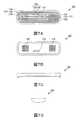
エミッタ120は、吐出口111を覆うようにチューブ110の内壁面に接合されている。エミッタ120の形状は、チューブ110の内壁面に密着して、吐出口111を覆うことができれば特に限定されない。本実施の形態では、チューブ110の軸方向に垂直なエミッタ120の断面における、チューブ110の内壁面に接合する裏面の形状は、チューブ110の内壁面に沿うように、チューブ110の内壁面に向かって凸の略円弧形状である。また、エミッタ120の平面形状は、四隅がR面取りされた略矩形である。エミッタ120の大きさは、特に限定されない。本実施の形態では、エミッタ120の長辺方向の長さは25mmであり、短辺方向の長さは8mmであり、高さは2.5mmである。 The
図2〜図4は、エミッタ120の構成を示す図である。図2Aは、エミッタ120を表面(第1面)側から見た斜視図であり、図2Bは、エミッタ120を裏面(第2面)側から見た斜視図である。図3Aは、エミッタ120の平面図であり、図3Bは、底面図であり、図3Cは、正面図であり、図3Dは、右側面図である。図4Aは、図3Aに示されるA−A線の断面図であり、図4Bは、図3Aに示されるB−B線の断面図であり、図4Cは、図3Aに示されるC−C線の断面図である。図5は、エミッタ本体121の構成を示す図である。図5Aは、エミッタ本体121の平面図であり、図5Bは、底面図であり、図5Cは、正面図であり、図5Dは、右側面図である。図6は、フィルム122の構成を示す図である。図6Aは、フィルム122の平面図であり、図6Bは、正面図であり、図6Cは、右側面図である。図7は、カバー123の構成を示す図である。図7Aは、カバー123の平面図であり、図7Bは、底面図であり、図7Cは、正面図であり、図7Dは、右側面図である。 2 to 4 are diagrams showing the configuration of the
図2〜図4に示されるように、エミッタ120は、エミッタ本体121と、フィルム122と、カバー123とから構成されている。すなわち、本実施の形態に係るエミッタ120は、3体構造である。また、エミッタ120は、取水部131と、減圧流路141と、流量減少部161と、流路開閉部171と、バイパス流路151と、吐出部181とを有する。 As shown in FIGS. 2 to 4, the
エミッタ本体121には、エミッタ120の主要な部分が形成されている。図4A〜Cおよび図5A〜Dに示されるように、本実施の形態では、エミッタ本体121には、減圧流路141を構成する減圧溝142と、流量減少部161を構成する流量減少用凹部162と、バイパス流路151を構成するバイパス溝152と、流路開閉部171を構成する流路開閉用凹部172と、吐出部181とが形成されている。減圧溝142と、流量減少用凹部162と、構成するバイパス溝152と、流路開閉用凹部172とは、第1面に開口している。また、吐出部181は、第2面に配置されている。 The main body of the
フィルム122は、チューブ110内の灌漑用液体の圧力に応じて変形し、吐出部181に送られる灌漑用液体の液量を調整する。フィルム122は、エミッタ本体121の表面(第1面)側に配置されている。フィルム122の平面視形状は、前述の機能を発揮できれば特に限定されない。図6A〜Cに示されるように、本実施の形態では、フィルム122の平面視形状は、エミッタ本体121の第1面の外形と同じである。また、図4A〜Cおよび図6A〜Cに示されるように、本実施の形態では、フィルム122は、流量減少部161を構成する第1ダイヤフラム部166と、流路開閉部171を構成する第2ダイヤフラム部176とを有し、かつ取水部131を構成する第2取水用貫通孔134が形成されている。フィルム122の厚さは、例えば0.3mmである。 The
カバー123は、フィルム122をエミッタ本体121の第1面に対して位置決めする。カバー123の形状は、前述の機能を発揮できれば特に限定されない。図7A〜Dに示されるように、本実施の形態では、カバー123は、1面を開放した箱状に形成されている。また、カバー123は、その内部にフィルム122を第1面に配置したエミッタ本体121を嵌め込むように形成されている。また、本実施の形態では、カバー123には、取水部131を構成する取水用スクリーン部132と、流量減少部161を構成する第1スクリーン部167と、流路開閉部171を構成する第2スクリーン部177とが形成されている。 The
フィルム122をエミッタ本体121の第1面側に配置し、フィルム122がカバー123の底面に接触するように、エミッタ本体121をカバー123に嵌め込むことで、エミッタ120が作製される。 The
エミッタ本体121およびカバー123の材料は、カバー123にエミッタ本体121を嵌め込むことができる程度の弾性を有していれば、特に限定されない。エミッタ本体121およびカバー123の材料の例には、ポリエチレンやシリコーンなどの樹脂と、ゴムとが含まれる。本実施の形態では、エミッタ本体121およびカバー123の材料は、製造コストおよび要求される弾性を満たす観点から、ポリエチレンである。また、フィルム122の材料は、チューブ110内の灌漑用液体の圧力に応じて適度に変形することができれば特に限定されない。フィルム122の材料の例には、ポリエチレンやシリコーンなどの樹脂と、ゴムとが含まれる。本実施の形態では、フィルム122の材料は、要求される弾性を満たす観点から、シリコーンである。なお、本実施の形態では、エミッタ本体121およびカバー123と、フィルム122とは、異なる材料で成形されているが、同じ材料でそれぞれ成形されていてもよい。エミッタ本体121、フィルム122およびカバー123の可撓性は、弾性を有する樹脂材料の使用によって調整することができる。エミッタ本体121、フィルム122およびカバー123の可撓性の調整方法の例には、弾性を有する樹脂の選択や、硬質の樹脂材料に対する弾性を有する樹脂材料の混合比の調整などが含まれる。エミッタ本体121、フィルム122およびカバー123は、例えば、射出成形によってそれぞれ製造できる。また、フィルム122は、市販されているフィルムを切り出して作製してもよい。 The material of the
エミッタ本体121の第1面にフィルム122を配置することにより、減圧溝142およびバイパス溝152は、それぞれ減圧流路141およびバイパス流路151となる。また、流量減少用凹部162および流路開閉用凹部172は、それぞれ流量減少部161および流路開閉部171となる。また、フィルム122が配置されたエミッタ本体121にカバー123が取り付けられることにより、取水用スクリーン部132、第1取水用貫通孔133および第2取水用貫通孔134は、取水部131となる。これにより、取水部131、減圧流路141、流量減少部161および吐出部181から構成され、取水部131と吐出部181とを繋ぐ第1流路153が形成される。また、取水部131、バイパス流路151、流路開閉部171および吐出部181から構成され、取水部131と吐出部181とを繋ぐ第2流路154が形成される。第1流路153および第2流路154は、いずれも取水部131から吐出部181まで灌漑用液体を流通させる。 By disposing the
取水部131は、エミッタ120の表面側に配置されている(図4A参照)。取水部131は、取水用スクリーン部132、第1取水用貫通孔133(図7A参照)および第2取水用貫通孔134(図6A参照)を有する。 The
取水用スクリーン部132は、エミッタ120に取り入れられる灌漑用液体中の浮遊物がエミッタ本体121内に侵入することを防止する。取水用スクリーン部132は、カバー123の表面側全体に形成されている。取水用スクリーン部132は、チューブ110内に対して開口しており、カバー凹部135および複数の凸条136を有する。 The water
カバー凹部135は、カバー123の上面の全体に形成されている1つの凹部である。カバー凹部135の深さは特に限定されず、エミッタ120の大きさによって適宜設定される。カバー凹部135の底面上には複数の凸条136が配置されている。また、カバー凹部135の底面には、第1取水用貫通孔133、流量減少用貫通孔168および流路開閉用貫通孔178がそれぞれ開口している(図7Aおよび図7B参照)。 The
複数の凸条136は、カバー凹部135の底面上に配置されている。凸条136の配置および数は、カバー凹部135の開口部側から灌漑用液体を取り入れつつ、灌漑用液体中の浮遊物の侵入を防止することができれば特に限定されない。本実施の形態では、凸条136は、エミッタ120の長軸方向に沿って配置されている。凸条136は、カバー凹部135の底面からカバー123の表面に向かうにつれて幅が小さくなるように形成されていてもよいし、カバー凹部135の底面からカバー123の表面まで同じ幅に形成されていてもよい。 The plurality of
第1取水用貫通孔133は、カバー凹部135の底面に開口している。第1取水用貫通孔133の形状および数は、カバー凹部135の内部に取り込まれた灌漑用液体を、第2取水用貫通孔134を介してエミッタ本体121内に導くことができれば特に限定されない。本実施の形態では、第1取水用貫通孔133は、カバー凹部135の底面の長軸方向に沿って形成された5つの矩形の穴である(図7B参照)。 The first water intake through
第2取水用貫通孔134は、フィルム122に形成されている。第2取水用貫通孔134の形状および数は、第1取水用貫通孔133から取り込まれた灌漑用液体を減圧流路141およびバイパス流路151に導くことができれば特に限定されない。本実施の形態では、第2取水用貫通孔134の形状は、2つの円形である(図6A参照)。 The second water intake through
チューブ110内を流れてきた灌漑用液体は、取水用スクリーン部132によって浮遊物がカバー凹部135内に侵入することが防止されつつ、第1取水用貫通孔133および第2取水用貫通孔134を介してエミッタ本体121内に取り込まれる。 The irrigation liquid flowing in the tube 110 is prevented from entering the cover recessed
減圧流路141(減圧溝142)は、流量減少部161より上流の第1流路153に配置されており、取水部131と、流量減少部161とを接続する。減圧流路141(減圧溝142)は、取水部131から取り入れられた灌漑用液体の圧力を減圧させて、流量減少部161に導く。減圧流路141は、エミッタ120の中央部分に配置されている。減圧流路141は、減圧溝142と、減圧溝142の開口部を塞ぐフィルム122とから構成されている。減圧溝142は、エミッタ本体121の表面(第1面)に形成されている。減圧溝142の形状は、減圧流路141となった場合に、前述の機能を発揮することができれば特に限定されない。本実施の形態では、減圧溝142の平面視形状は、ジグザグ形状である。減圧溝142は、内側面から突出する略三角柱形状の凸部143が灌漑用液体の流れる方向に沿って交互に配置されている。凸部143は、平面視したときに、先端が減圧溝142の中心軸を超えないように配置されている。フィルム122がエミッタ本体121の第1面に配置されることにより、減圧溝142と、フィルム122の裏面の一部とにより、減圧流路141が形成される。取水部131から取り込まれた灌漑用液体のうち、少なくとも一部の灌漑用液体は、減圧流路141により減圧されて流量減少部161に導かれる。詳細は後述するが、減圧流路141は、主として灌漑用液体の圧力が高圧の場合に機能する。 The decompression flow path 141 (decompression groove 142) is arranged in the
バイパス流路151(バイパス溝152)は、流路開閉部171より上流の第2流路154に配置されており、取水部131および流路開閉部171を接続する。バイパス流路151(バイパス溝152)は、取水部131から取り入れられた灌漑用液体の圧力を、減圧流路141(減圧溝142)を流れた灌漑用液体の圧力より高い圧力を維持した状態で、流路開閉部171に導く。フィルム122がエミッタ本体121の第1面に配置されることにより、バイパス溝152と、フィルム122の裏面の一部とにより、バイパス流路151が形成される。取水部131から取り込まれた灌漑用液体のうち、一部の灌漑用液体は、バイパス流路151を通過して流路開閉部171に導かれる。詳細は後述するが、バイパス流路151は、灌漑用液体の圧力が低圧の場合にのみ機能する。 The bypass flow passage 151 (bypass groove 152) is arranged in the
なお、バイパス溝152には、流路用スクリーン部が配置されていてもよい。流路用スクリーン部は、取水用スクリーン部132で捕集できなかった灌漑用液体中の浮遊物を捕集する。流路用スクリーン部の形態は、前述の機能を発揮することができれば特に限定されない。たとえば、流路用スクリーン部は、バイパス溝152の底面上に配置された、円柱形状の複数の突起である。 The
流量減少部161は、第1流路153内において減圧流路141と吐出部181との間に配置されている。流量減少部161は、チューブ110内の灌漑用液体の圧力に応じて灌漑用液体の流量を減少させつつ、灌漑用液体を吐出部181に送る。流量減少部161の構成は、前述の機能を発揮することができれば特に限定されない。本実施の形態では、流量減少部161は、流量減少用凹部162と、第1弁座部163と、連通溝164と、吐出部181に連通した第1吐出用貫通孔165と、フィルム122の一部である第1ダイヤフラム部166と、第1スクリーン部167と、を有する。 The flow
流量減少用凹部162の平面視形状は、特に限定されない。流量減少用凹部162の平面視形状は、四隅がR面取りされた略矩形であってもよいし、略円形であってもよい。本実施の形態では、流量減少用凹部162の平面視形状は、四隅がR面取りされた略矩形である。流量減少用凹部162の底面には、吐出部181に連通した第1吐出用貫通孔165が開口しており、第1弁座部163が配置されている。また、流量減少用凹部162の側面には、減圧流路141(減圧溝142)が接続されている。流量減少用凹部162の深さは、特に限定されず、連通溝164および減圧溝142の深さ以上であればよい。 The plan view shape of the flow
第1吐出用貫通孔165は、流量減少用凹部162の底面の中央部分に開口しており、吐出部181に連通している。第1弁座部163は、第1吐出用貫通孔165を取り囲むように流量減少用凹部162の底面に配置されている。第1弁座部163は、チューブ110を流れる灌漑用液体の圧力が第2圧力以上の場合に、第1ダイヤフラム部166が密着可能に形成されている。第1弁座部163に第1ダイヤフラム部166が接触することによって、流量減少用凹部162から吐出部181に流れ込む灌漑用液体の流量を減少させる。第1弁座部163の形状は、前述の機能を発揮することができれば特に限定されない。本実施の形態では、第1弁座部163の形状は、円環状の凸部である。第1弁座部163の第1ダイヤフラム部166が密着可能な領域の一部には、流量減少用凹部162の内部と第1吐出用貫通孔165を連通する連通溝164が形成されている。 The first discharge through
第1ダイヤフラム部166は、フィルム122の一部である。第1ダイヤフラム部166は、流量減少用凹部162の内部とチューブ110の内部とを仕切るように配置されている。第1ダイヤフラム部166は、チューブ110内の灌漑用液体の圧力に応じて、第1弁座部163に接触するように変形する。具体的には、第1ダイヤフラム部166は、灌漑用液体の圧力が高くなるにつれて、第1弁座部163に向かって変形し、やがて第1弁座部163に接触する。第1ダイヤフラム部166が第1弁座部163に密着している場合であっても、第1ダイヤフラム部166は、減圧流路141の端部、第1吐出用貫通孔165および連通溝164を閉塞しないため、減圧流路141から送られてきた灌漑用液体は、連通溝164および第1吐出用貫通孔165を通って、吐出部181に送られうる。 The
第1スクリーン部167は、灌漑用液体の圧力をほとんど変化させることなく、灌漑用液体を第1ダイヤフラム部166の表面に送る。第1スクリーン部167は、カバー凹部135の一部と、一部の凸条136と、流量減少用貫通孔168とを有する。流量減少用貫通孔168は、カバー123の底部であって、第1ダイヤフラム部166に対応した位置に形成されている。流量減少用貫通孔168の形状および数は、前述の機能を発揮できれば特に限定されない。流量減少用貫通孔168の平面視形状は、円形であってもよいし、矩形であってもよい。本実施の形態では、流量減少用貫通孔168の平面視形状は、矩形である。また、流量減少用貫通孔168の数は、単数であってもよいし、複数であってもよい。本実施の形態では、流量減少用貫通孔168の数は、カバー凹部135の底面の短軸方向に沿って形成された5つの長孔である。それぞれの長孔は、複数の凸条136により覆われているため、表側から見た場合、1つの流量減少用貫通孔168は、多数の貫通孔に分かれているように見える The
流路開閉部171は、第2流路154内において、バイパス流路151と吐出部181との間に配置されている。流路開閉部171は、チューブ110内の圧力に応じて第2流路154を開放して、灌漑用液体を吐出部181に送る。流路開閉部171の構成は、前述の機能を発揮することができれば特に限定されない。本実施の形態では、流路開閉部171は、流路開閉用凹部172と、第2弁座部173と、吐出部181に連通した第2吐出用貫通孔175と、フィルム122の一部である第2ダイヤフラム部176と、第2スクリーン部177と、を有する。 The flow path opening /
流路開閉用凹部172の平面視形状は、特に限定されない。流路開閉用凹部172の平面視形状は、四隅がR面取りされた略矩形であってもよいし、略円形であってもよい。本実施の形態では、流路開閉用凹部172の平面視形状は、四隅がR面取りされた略矩形である。流路開閉用凹部172の底面には、吐出部181に連通した第2吐出用貫通孔175と、第2弁座部173とが配置されている。また、流路開閉用凹部172の側面には、バイパス流路151(バイパス溝152)が接続されている。第2弁座部173は、第1弁座部163より第1面側に位置するように形成されている。これにより、フィルム122が灌漑用液体の圧力により変形した場合に、フィルム122は、第1弁座部163より先に第2弁座部173に接触する。 The plan view shape of the flow path opening /
第2吐出用貫通孔175は、流路開閉用凹部172の底面の中央部分に開口しており、吐出部181に連通している。第2弁座部173は、第2吐出用貫通孔175を取り囲むように流路開閉用凹部172の底面に配置されている。また、第2弁座部173は、第2ダイヤフラム部176に面して非接触に配置され、チューブ110を流れる灌漑用液体の圧力が第1圧力以上の場合、第2ダイヤフラム部176が密着できるように形成されている。チューブ110を流れる灌漑用液体の圧力が第1圧力以上の場合、第2ダイヤフラム部176は、第2弁座部173に密着して第2吐出用貫通孔175を閉塞し、その結果として第2流路154を閉塞する。第2弁座部173の形状は、前述の機能を発揮することができれば特に限定されない。本実施の形態では、第2弁座部173は、円環状の凸部である。 The second discharge through
第2ダイヤフラム部176は、フィルム122の一部である。第2ダイヤフラム部176は、流路開閉用凹部172の内部とチューブ110の内部とを仕切るように配置されている。第2ダイヤフラム部176は、チューブ110内の灌漑用液体の圧力に応じて、第2弁座部173に接触するように変形する。具体的には、第2ダイヤフラム部176は、灌漑用液体の圧力が高くなるにつれて、第2弁座部173に向かって変形し、灌漑用液体の圧力が第1圧力に到達すると、第2弁座部173に接触する。これにより、第2流路154(第2吐出用貫通孔175)は閉塞される。 The
第2スクリーン部177は、灌漑用液体の圧力をほとんど変化させることなく、灌漑用液体を第2ダイヤフラム部176の表面に送る。第2スクリーン部177は、カバー凹部135の一部と、一部の凸条136と、流路開閉用貫通孔178とを有する。流路開閉用貫通孔178は、カバー123の底部であって、第2ダイヤフラム部176に対応した位置に形成されている。流路開閉用貫通孔178の形状および数は、前述の機能を発揮できれば特に限定されない。流路開閉用貫通孔178の平面視形状は、円形であってもよいし、矩形であってもよい。本実施の形態では、流路開閉用貫通孔178の平面視形状は、矩形である。また、流路開閉用貫通孔178の数は、単数であってもよいし、複数であってもよい。本実施の形態では、流路開閉用貫通孔178の数は、カバー凹部135の底面の短軸方向に沿って形成された5つの長孔である。それぞれの長孔は、複数の凸条136により覆われているため、表側から見た場合、1つの流路開閉用貫通孔178は、多数の貫通孔に分かれているように見える。 The
吐出部181は、吐出口111に面するエミッタ120の裏面側に配置されている。吐出部181は、第1吐出用貫通孔165および第2吐出用貫通孔175からの灌漑用液体をチューブ110の吐出口111に送る。吐出部181の構成は、前述の機能を発揮することができれば特に限定されない。本実施の形態では、吐出部181は、吐出用凹部182と、一対の吐出用溝183と、一対の侵入防止部184とを有する。 The
吐出用凹部182は、エミッタ本体121の裏面に開口している。吐出用凹部182の平面視形状は、略矩形である。吐出用凹部182の対向する側面には、一対の吐出用溝183が対向して開口している。 The
一対の侵入防止部184は、吐出口111からの異物の侵入を防止する。侵入防止部184の位置は、前述の機能を発揮することができれば特に限定されない。本実施の形態では、侵入防止部184は、エミッタ120をチューブ110に接合した場合に、第1吐出用貫通孔165および吐出口111の間と、第2吐出用貫通孔175および吐出口の間とに位置するように配置されている。 The pair of
(点滴灌漑用チューブおよびエミッタの動作)
次に、点滴灌漑用チューブ100の動作について説明する。まず、チューブ110内に灌漑用液体が送液される。灌漑用液体の例には、水、液体肥料、農薬およびこれらの混合液が含まれる。点滴灌漑用チューブ100へ送液される灌漑用液体の圧力は、簡易に点滴灌漑法を導入できるように、またチューブ110およびエミッタ120の破損を防止するため、0.1MPa以下であることが好ましい。チューブ110内の灌漑用液体は、取水部131からエミッタ本体121内に取り込まれる。具体的には、チューブ110内の灌漑用液体は、凸条136間の隙間からカバー凹部135に入り込み、第1取水用貫通孔133および第2取水用貫通孔134を通過する。このとき、取水部131は、取水用スクリーン部132(凸条136間の隙間)を有しているため、灌漑用液体中の浮遊物を除去することができる。(Operation of drip irrigation tube and emitter)
Next, the operation of the
取水部131から取り込まれた灌漑用液体は、バイパス流路151の上流端部に到達する。バイパス流路151に到達した灌漑用液体は、バイパス流路151の下流に向かって流れ出すとともに、減圧流路141に流れ込む。このとき、灌漑用液体は、減圧流路141と比較して圧力損失の少ないバイパス流路151を先行して進む。バイパス流路151に流れ込んだ灌漑用液体は、流路開閉部171に流れ込む。 The irrigation liquid taken in from the
流路開閉部171に流れ込んだ灌漑用液体は、流路開閉部171が開いている場合には吐出部181に流れ込む。吐出部181に流れ込んだ灌漑用液体は、チューブ110の吐出口111からチューブ110外に吐出される。一方、減圧流路141に流れ込んだ灌漑用液体は、流量減少部161に到達する。流量減少部161に流れ込んだ灌漑用液体は、吐出部181に流れ込む。吐出部181に流れ込んだ灌漑用液体は、チューブ110の吐出口111からチューブ110外に吐出される。 The irrigation liquid that has flowed into the flow path opening /
前述したように、流量減少部161では、チューブ110内の灌漑用液体の圧力に応じて第1ダイヤフラム部166によって灌漑用液体の流量が制御され、流路開閉部171では、チューブ110内の灌漑用液体の圧力に応じて第2ダイヤフラム部176によって灌漑用液体の流量が制御される。そこで、チューブ110内の灌漑用液体の圧力に応じた流路開閉部171および流量減少部161の動作について説明する。 As described above, in the flow
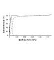
図8A〜Cは、流量減少部161と、流路開閉部171との動作の関係を示すエミッタ120の断面図である。図8Aは、チューブ110に灌漑用液体が送液されていない場合における断面図であり、図8Bは、チューブ110内の灌漑用液体の圧力が第1圧力である場合における断面図であり、図8Cは、チューブ110内の灌漑用液体の圧力が第1圧力を超える第2圧力である場合における断面図である。図9は、チューブ110内の灌漑用液体の圧力と、吐出口111から滴下される灌漑用液体の流量との関係の一例を示すグラフである。図9の実線は、吐出口111から滴下される灌漑用液体の総流量を示しており、図9の破線は、第2流路154を流れた(バイパス流路151を通った)灌漑用液体の流量を示しており、図9の一点鎖線は、第1流路153を流れた(減圧流路141を通った)灌漑用液体の流量を示している。図9の横軸は、灌漑用液体の圧力(MPa)を示しており、縦軸は、吐出口111から吐出された灌漑用液体の流量(L/h)を示している。 8A to 8C are cross-sectional views of the
チューブ110内に灌漑用液体を送液する前では、フィルム122に灌漑用液体の圧力が加わらないため、第1ダイヤフラム部166および第2ダイヤフラム部176は、変形していない(図8A参照)。 Before the irrigation liquid is fed into the tube 110, the pressure of the irrigation liquid is not applied to the
チューブ110内に灌漑用液体を送液し始めると、流量減少部161の第1ダイヤフラム部166は、第1弁座部163に向かって変形し始める。また、流路開閉部171の第2ダイヤフラム部176は、第2弁座部173に向かって変形し始める。しかしながら、この状態では、第1ダイヤフラム部166が第1弁座部163に接触しておらず、かつ第2ダイヤフラム部176が第2弁座部173に接触していないため、取水部131から取り入れられた灌漑用液体は、第1流路153(減圧流路141、流量減少部161および吐出部181)および第2流路154(バイパス流路151、流路開閉部171、流量減少部161および吐出部181)の両方を通って、チューブ110の吐出口111から外部に吐出される。このように、チューブ110内への灌漑用液体の送液開始時や、チューブ110内の灌漑用液体の圧力が低圧の場合などでは、取水部131から取り入れられた灌漑用液体は、減圧流路141およびバイパス流路151の両方を通って吐出される。 When the liquid for irrigation is started to be fed into the tube 110, the
チューブ110内の灌漑用液体の圧力が第1圧力に到達すると、第2ダイヤフラム部176が第2弁座部173に接触して、第2流路154を閉塞する(図8B参照)。このとき、第1ダイヤフラム部166は、第1弁座部163に接触していない。このように、チューブ110内の灌漑用液体の圧力がフィルム122を変形させるほど高くなると、第2ダイヤフラム部176が第2弁座部173に近接するため、第2流路154を通って吐出される灌漑用液体の液量は減少する。そして、チューブ110内の灌漑用液体の圧力が第1圧力に到達すると、第2流路154内の灌漑用液体は、吐出口111から吐出されなくなる。その結果、取水部131から取り入れられた灌漑用液体は、第1流路153を通って、チューブ110の吐出口111から外部に吐出される。 When the pressure of the irrigation liquid in the tube 110 reaches the first pressure, the
チューブ110内の灌漑用液体の圧力がさらに高まると、第1ダイヤフラム部166は、第1弁座部163に向かってさらに変形する。通常は、灌漑用液体の圧力が高くなるにつれて、第1流路153を流れる灌漑用液体の量が増大するはずであるが、本実施の形態に係るエミッタ120では、減圧流路141で灌漑用液体の圧力を減少させるとともに、第1ダイヤフラム部166と第1弁座部163との間隔を狭めることで、第1流路153を流れる灌漑用液体の量の過剰な増大を防止している。そして、チューブ110内の灌漑用液体の圧力が第1圧力を超える第2圧力以上である場合に、第1ダイヤフラム部166は、第1弁座部163に接触する(図8C参照)。この場合であっても、第1ダイヤフラム部166は、流量減少用貫通孔168、連通溝164および第1吐出用貫通孔165を塞がないため、取水部131から取り入れられた灌漑用液体は、連通溝164を通って、チューブ110の吐出口111から外部に吐出される。このように、流量減少部161は、チューブ110内の灌漑用液体の圧力が第2圧力以上である場合、第2ダイヤフラム部176が第2弁座部173に接触することにより、第1流路153を流れる灌漑用液体の液量の増大を抑制する(図9に示される一点鎖線参照)。 When the pressure of the irrigation liquid in the tube 110 is further increased, the
このように、流量減少部161および流路開閉部171は、チューブ110内の灌漑用液体の圧力に応じて、それぞれを流れる液量が相互に補完されるように機能するため、本実施の形態に係る点滴灌漑用チューブ100は、灌漑用液体の圧力が低圧および高圧のいずれの場合であっても、一定量の灌漑用液体をチューブ110外に吐出できる(図9に示される実線参照)。 As described above, the flow
(効果)
以上のように、本実施の形態に係る点滴灌漑用チューブ100は、主として低圧時に作動する流路開閉部171と、主として高圧時に作動する流量減少部161を有するため、チューブ110内の灌漑用液体の圧力に依存せず、灌漑用液体を定量的に滴下することができる。(effect)
As described above, since the
なお、本実施の形態では、減圧溝142およびバイパス溝152は、第1面に開口しており、フィルム122によりそれぞれの開口部を塞ぐことで、第1流路153および第2流路154となるが、それぞれ第2面に開口していてもよい。この場合、減圧溝142の開口部およびバイパス溝152の開口部は、チューブ110の内壁面で塞がれる。また、第1流路153および第2流路154は、エミッタ本体121の内部にそれぞれ形成されていてもよい。 In addition, in the present embodiment, the
なお、本実施の形態では、第1弁座部163および第2弁座部173の位置(高さ)を変えることにより、フィルム122が変形した場合に接触するタイミングを調整したが、第1弁座部163および第2弁座部173の位置(高さ)は、同じ深さであってもよい。この場合、第1ダイヤフラム部166および第2ダイヤフラム部176の厚みや材料(弾性)を変えることにより、フィルム122が変形した場合に接触するタイミングを調整してもよい。 In the present embodiment, the contact timing when the
また、本実施の形態では、流量減少部161および流路開閉部171は、独立しているが、流量減少部161および流路開閉部171は連通していてもよい。 Further, in the present embodiment, the flow
本発明によれば、滴下すべき液体の圧力によって適切な速度での液体の滴下が可能なエミッタを簡易に提供することが可能である。したがって、点滴灌漑や耐久試験などの、長期の滴下を要する技術分野への上記エミッタの普及および当該技術分野のさらなる発展が期待される。 According to the present invention, it is possible to easily provide an emitter capable of dropping liquid at an appropriate speed depending on the pressure of the liquid to be dropped. Therefore, it is expected that the emitter will be spread to technical fields that require long-term drip such as drip irrigation and durability test, and further development of the technical fields.
100 点滴灌漑用チューブ
110 チューブ
111 吐出口
120 エミッタ
121 エミッタ本体
122 フィルム
123 カバー
131 取水部
132 取水用スクリーン部
133 第1取水用貫通孔
134 第2取水用貫通孔
135 カバー凹部
136 凸条
141 減圧流路
142 減圧溝
143 凸部
151 バイパス流路
152 バイパス溝
153 第1流路
154 第2流路
161 流量減少部
162 流量減少用凹部
163 第1弁座部
164 連通溝
165 第1吐出用貫通孔
166 第1ダイヤフラム部
167 第1スクリーン部
168 流量減少用貫通孔
171 流路開閉部
172 流路開閉用凹部
173 第2弁座部
175 第2吐出用貫通孔
176 第2ダイヤフラム部
177 第2スクリーン部
178 流路開閉用貫通孔
181 吐出部
182 吐出用凹部
183 吐出用溝
184 侵入防止部100 Drip irrigation tube 110 Tube 111
Claims (6)
Translated fromJapanese前記灌漑用液体を取り入れるための取水部と、
前記第1面と表裏関係にあり、前記吐出口に面する前記エミッタ本体の第2面に配置され、前記灌漑用液体を吐出するための吐出部と、
前記取水部および前記吐出部を繋ぎ、前記灌漑用液体を流通させる第1流路と、
前記取水部および前記吐出部を繋ぎ、前記灌漑用液体を流通させる第2流路と、
前記第1面に開口した流量減少用凹部および前記流量減少用凹部の開口部を塞いだ前記フィルムを含み、前記第1流路に配置され、前記チューブ内の前記灌漑用液体の圧力に応じて、前記フィルムが変形することにより前記吐出口への前記灌漑用液体の流量を減少させる流量減少部と、
前記第1面に開口した流路開閉用凹部および前記流路開閉用凹部の開口部を塞いだ前記フィルムを含み、前記第2流路に配置され、前記チューブ内の前記灌漑用液体の圧力に応じて、前記フィルムが変形することにより前記第2流路を開放および閉塞する流路開閉部と、
前記流量減少部より上流の前記第1流路に配置され、前記取水部から取り入れられた前記灌漑用液体の圧力を減圧させて、前記流量減少部に導く減圧流路と、
前記流路開閉部より上流の前記第2流路に配置され、前記取水部から取り入れられた前記灌漑用液体の圧力を、前記減圧流路を流れた前記灌漑用液体の圧力より高い圧力を維持した状態で、前記流路開閉部に導くバイパス流路と、
を有し、
前記チューブを流れる前記灌漑用液体の圧力が第1圧力未満の場合、前記取水部から取り入れられた前記灌漑用液体は、前記減圧流路および前記バイパス流路を通って、前記吐出部に導かれ、
前記チューブを流れる前記灌漑用液体の圧力が前記第1圧力以上である場合、前記流路開閉部により前記第2流路が閉塞され、前記取水部から取り入れられた前記灌漑用液体は、前記減圧流路を通って前記吐出部に導かれる、
エミッタ。An emitter main body, a flexible film arranged on the first surface side of the emitter main body, and a cover for positioning the film with respect to the emitter main body, and circulates the irrigation liquid. An emitter that is an inner wall surface of the tube and is joined to a position corresponding to a discharge port that communicates the inside and the outside of the tube, and that quantitatively discharges the irrigation liquid in the tube from the discharge port to the outside of the tube. And
An intake part for taking in the irrigation liquid,
An ejecting portion which is in front-back relation with the first surface and which is disposed on the second surface of the emitter body facing the ejection port and ejects the irrigation liquid;
A first flow path that connects the water intake section and the discharge section and circulates the irrigation liquid;
A second flow path for connecting the water intake section and the discharge section and allowing the irrigation liquid to circulate;
It includes a flow rate reducing recess opened on the first surface and the film closing the opening of the flow rate reducing recess, is arranged in the first flow path, and is arranged according to the pressure of the irrigation liquid in the tube. A flow rate reducing section that reduces the flow rate of the irrigation liquid to the discharge port by deforming the film,
The flow path opening / closing recess opening on the first surface and the film closing the opening of the flow path opening / closing recess are disposed in the second flow path, and are set to the pressure of the irrigation liquid in the tube. Accordingly, a flow path opening / closing portion that opens and closes the second flow path by deforming the film,
A decompression flow path that is arranged in the first flow path upstream of the flow rate reduction section, reduces the pressure of the irrigation liquid taken in from the water intake section, and leads to the flow rate reduction section;
The pressure of the irrigation liquid, which is arranged in the second flow path upstream of the flow path opening / closing section and is taken from the water intake section, is maintained higher than the pressure of the irrigation liquid that has flowed through the decompression flow path. A bypass flow path leading to the flow path opening / closing section in a state where
Have
When the pressure of the irrigation liquid flowing through the tube is less than a first pressure, the irrigation liquid taken from the water intake part is guided to the discharge part through the depressurization flow path and the bypass flow path. ,
When the pressure of the irrigation liquid flowing through the tube is equal to or higher than the first pressure, the flow passage opening / closing unit closes the second flow passage, and the irrigation liquid taken from the water intake unit is reduced in pressure. Guided to the discharge section through a flow path,
The emitter.
前記減圧流路からの前記灌漑用液体は、前記流量減少部を通って前記吐出部に導かれ、
前記バイパス流路からの前記灌漑用液体は、前記流路開閉部を通って前記吐出部に導かれる、
請求項1に記載のエミッタ。The flow rate reducing section and the flow path opening / closing section are independent,
The irrigation liquid from the reduced pressure flow path is guided to the discharge unit through the flow rate reduction unit,
The irrigation liquid from the bypass channel is guided to the discharge section through the channel opening / closing section,
The emitter according to claim 1.
前記減圧流路が内面に開口した前記流量減少用凹部と、
前記流量減少用凹部の内部と前記チューブの内部とを仕切るように配置された、前記フィルムの第1ダイヤフラム部と、
前記流量減少用凹部の内面に開口し、前記吐出部に連通する流量減少用貫通孔と、
前記流量減少用貫通孔を取り囲むように、前記第1ダイヤフラム部に面して非接触に配置され、前記チューブを流れる前記灌漑用液体の圧力が前記第1圧力を超える第2圧力以上の場合、前記第1ダイヤフラム部が密着可能な第1弁座部と、
前記第1弁座部の前記第1ダイヤフラム部が密着可能な面に形成され、前記流量減少用凹部の内部と前記流量減少用貫通孔とを連通する連通溝と、を含む、
請求項1または請求項2に記載のエミッタ。The flow rate reducing section,
The flow rate reducing recess having an opening on the inner surface of the pressure reducing channel,
A first diaphragm portion of the film, which is arranged so as to partition the inside of the recess for flow rate reduction and the inside of the tube;
A flow rate reducing through hole that opens to the inner surface of the flow rate reducing recess and communicates with the discharge section;
When the pressure of the irrigation liquid flowing through the tube is equal to or higher than a second pressure, which is arranged in a non-contact manner so as to surround the flow rate reducing through hole and faces the first diaphragm portion, A first valve seat portion to which the first diaphragm portion can adhere,
A communication groove that is formed on a surface of the first valve seat portion to which the first diaphragm portion can adhere, and includes a communication groove that communicates the inside of the flow rate reducing recess with the flow rate reducing through hole.
The emitter according to claim 1 or 2.
前記バイパス流路が内面に開口した前記流路開閉用凹部と、
前記流路開閉用凹部の内部と前記チューブの内部とを仕切るように配置された、前記フィルムの第2ダイヤフラム部と、
前記流路開閉用凹部の内面に開口し、前記吐出部に連通する流路開閉用貫通孔と、
前記流路開閉用貫通孔を取り囲むように、前記第2ダイヤフラム部に面して非接触に配置され、前記チューブを流れる前記灌漑用液体の圧力が前記第1圧力以上の場合、前記第2ダイヤフラム部が密着可能な第2弁座部と、を含む、
請求項1〜3のいずれか一項に記載のエミッタ。The flow path opening and closing unit,
The flow path opening and closing recessed portion in which the bypass flow path is open to the inner surface,
A second diaphragm portion of the film, arranged so as to partition the inside of the flow path opening / closing recess and the inside of the tube;
A flow path opening / closing through hole that opens to the inner surface of the flow path opening / closing recess and communicates with the discharge unit,
When the pressure of the irrigation liquid flowing through the tube is equal to or higher than the first pressure, the second diaphragm is arranged in a non-contact manner so as to surround the flow path opening / closing hole and faces the second diaphragm portion. A second valve seat portion that can be in close contact with the portion,
The emitter according to any one of claims 1 to 3.
前記チューブの内壁面の前記吐出口に対応する位置に接合された、請求項1〜5のいずれか一項に記載のエミッタと、
を有する、点滴灌漑用チューブ。A tube having a discharge port for discharging the irrigation liquid,
The emitter according to any one of claims 1 to 5, which is joined to a position corresponding to the discharge port on the inner wall surface of the tube,
A drip irrigation tube.
Priority Applications (6)
| Application Number | Priority Date | Filing Date | Title |
|---|---|---|---|
| JP2016054104AJP6689634B2 (en) | 2016-03-17 | 2016-03-17 | Emitter and drip irrigation tubes |
| EP17766256.6AEP3430888A4 (en) | 2016-03-17 | 2017-02-22 | DROPPER AND TUBE FOR DROP-IN-DROP IRRIGATION |
| CN201780016312.3ACN108882681A (en) | 2016-03-17 | 2017-02-22 | Transmitter and trickle irrigation delivery pipe |
| US16/085,685US10806104B2 (en) | 2016-03-17 | 2017-02-22 | Emitter, and tube for drip irrigation |
| PCT/JP2017/006564WO2017159251A1 (en) | 2016-03-17 | 2017-02-22 | Emitter, and tube for drip irrigation |
| IL261800AIL261800A (en) | 2016-03-17 | 2018-09-16 | Emitter, and tube for drip irrigation |
Applications Claiming Priority (1)
| Application Number | Priority Date | Filing Date | Title |
|---|---|---|---|
| JP2016054104AJP6689634B2 (en) | 2016-03-17 | 2016-03-17 | Emitter and drip irrigation tubes |
Publications (2)
| Publication Number | Publication Date |
|---|---|
| JP2017163925A JP2017163925A (en) | 2017-09-21 |
| JP6689634B2true JP6689634B2 (en) | 2020-04-28 |
Family
ID=59850258
Family Applications (1)
| Application Number | Title | Priority Date | Filing Date |
|---|---|---|---|
| JP2016054104AExpired - Fee RelatedJP6689634B2 (en) | 2016-03-17 | 2016-03-17 | Emitter and drip irrigation tubes |
Country Status (6)
| Country | Link |
|---|---|
| US (1) | US10806104B2 (en) |
| EP (1) | EP3430888A4 (en) |
| JP (1) | JP6689634B2 (en) |
| CN (1) | CN108882681A (en) |
| IL (1) | IL261800A (en) |
| WO (1) | WO2017159251A1 (en) |
Families Citing this family (2)
| Publication number | Priority date | Publication date | Assignee | Title |
|---|---|---|---|---|
| JP6719297B2 (en)* | 2016-06-29 | 2020-07-08 | 株式会社エンプラス | Emitter and drip irrigation tubes |
| IL259501B2 (en)* | 2018-05-21 | 2024-12-01 | Ari Nimrod | Dripper for periodic, volumetric irrigation |
Family Cites Families (90)
| Publication number | Priority date | Publication date | Assignee | Title |
|---|---|---|---|---|
| US2762397A (en)* | 1952-06-24 | 1956-09-11 | Hays Mfg Co | Flow control device |
| US3777980A (en)* | 1972-11-03 | 1973-12-11 | Allport Davies | Irrigation fitting |
| US3896999A (en)* | 1973-09-28 | 1975-07-29 | Jaime Sahagun Barragan | Anti-clogging drip irrigation valve |
| IL44502A (en)* | 1974-03-26 | 1979-10-31 | Lego Lemelstrich Ltd | Flow restrictor for irrigation systems |
| US4054152A (en)* | 1975-03-11 | 1977-10-18 | Nippondenso Co., Ltd. | Check valve |
| US4084749A (en)* | 1976-04-11 | 1978-04-18 | Mordeki Drori | Flow reducing devices particularly useful as drip emitters for drip irrigation |
| IL50766A (en)* | 1976-10-26 | 1983-06-15 | Hydro Plan Eng Ltd | Irrigation emitter unit |
| DE2729458C3 (en)* | 1977-06-30 | 1981-07-16 | Arcu Armaturindustri AB, Alstermo | Flow regulator, especially for installation between a water crane and a water pipe end |
| IL67824A (en)* | 1977-11-24 | 1985-08-30 | Hydro Plan Eng Ltd | Irrigation drip emitter unit |
| US4161291A (en)* | 1978-11-01 | 1979-07-17 | Clarence Bentley | Emitter |
| IL58176A0 (en)* | 1979-09-04 | 1979-12-30 | Bron Dan | A self-regulating nozzle for a liquid supply line |
| US4344576A (en)* | 1980-09-15 | 1982-08-17 | Smith Allan L | Trickle flow irrigation valve |
| US4613080A (en)* | 1984-06-29 | 1986-09-23 | Rain Bird Sprinkler Mfg. Corp. | Multiple outlet trickle irrigation unit |
| US4817875A (en)* | 1987-09-21 | 1989-04-04 | David Karmeli | Flexible pipe for trickle irrigation |
| US5183208A (en)* | 1990-07-20 | 1993-02-02 | Agroteam Consultants Ltd. | Drip irrigation emitter |
| IL96106A (en)* | 1990-10-25 | 1998-04-05 | Hydro Plan Eng Ltd | Fluid flow control unit for example for an irrigation emitter |
| US5111996A (en)* | 1991-02-27 | 1992-05-12 | Drip Irrigation Systems, Ltd. | Incremental pressure-compensating drip irrigation emitter |
| US5400973A (en)* | 1993-07-30 | 1995-03-28 | Cohen; Amir | Pressure responsive regulated flow restrictor useful for drip irrigation |
| US5636797A (en)* | 1993-07-30 | 1997-06-10 | Cohen; Amir | Drip irrigation emitter and flow control unit included therein |
| US5413282A (en)* | 1993-10-28 | 1995-05-09 | James Hardie Irrigation, Inc. | Pressure compensating emitter with shut down flush |
| US5465905A (en)* | 1994-03-17 | 1995-11-14 | Mister Dripper Company, Llc | Irrigation system with multi-functional irrigation control valves |
| US6085986A (en)* | 1994-05-03 | 2000-07-11 | Yu; Michael | Oscillating disk drives |
| US5711482A (en)* | 1994-05-03 | 1998-01-27 | Yu; Michael | Resilient disk drip irrigation devices |
| US5615838A (en)* | 1995-03-10 | 1997-04-01 | Drip Irrigation Systems, Ltd. | In-line retention drip emitter |
| US5727733A (en)* | 1996-01-19 | 1998-03-17 | Gideon Ruttenberg | Pulsating devices |
| US5813603A (en)* | 1996-02-16 | 1998-09-29 | Vernay Laboratories, Inc. | Low throughput water system flow control members and methods of inhibiting swelling of such members |
| IL118377A (en)* | 1996-05-22 | 2001-12-23 | Cohen Amir | Irrigation emitters having reduced sensitivity to clogging |
| US5820029A (en)* | 1997-03-04 | 1998-10-13 | Rain Bird Sprinkler, Mfg. Corp. | Drip irrigation emitter |
| IL121967A (en)* | 1997-10-14 | 2001-06-14 | Hydro Plan Eng Ltd | Emitter unit |
| IL122777A (en)* | 1997-12-28 | 2003-12-10 | Amir Cohen | Valve controlled drip irrigation lines |
| US5988211A (en)* | 1998-07-06 | 1999-11-23 | Randolph W. Cornell | I.V. flow controller |
| IL131716A (en)* | 1998-12-21 | 2006-09-05 | Amir Cohen | Drip irrigation emitters |
| GR20000100065A (en)* | 2000-02-28 | 2001-10-31 | Emitter with water inlet filter and method of assembly thereof | |
| US6464152B1 (en)* | 2000-04-06 | 2002-10-15 | Eurodrip, S.A. | Self-cleaning pressure compensating irrigation drip emitter |
| US6886761B2 (en)* | 2000-08-21 | 2005-05-03 | Amir Cohen | Drip irrigation hose and method and apparatus for making same |
| WO2002074444A2 (en)* | 2001-03-16 | 2002-09-26 | The Toro Company | Drip irrigation emitter |
| ITSV20010012A1 (en)* | 2001-04-20 | 2002-10-20 | Irritec Srl | SELF-COMPENSATING EMITTER FOR DROP DROP IRRIGATION |
| WO2004018794A1 (en)* | 2002-08-11 | 2004-03-04 | Hugo Weber | Cleaning system for surfaces exposed to poor weather conditions |
| ES2223241B1 (en)* | 2002-10-02 | 2006-05-16 | Irrimon, S.A.U. | SELF-COMPENSATING DRIP IRRIGATION ISSUER, WITH UNIDIRECTIONAL FLOW DEVICE. |
| US20050284966A1 (en)* | 2004-06-23 | 2005-12-29 | Defrank Michael | Emitter |
| US20060144965A1 (en)* | 2005-01-05 | 2006-07-06 | Ron Keren | Irrigation flushing system |
| IL167015A (en)* | 2005-02-21 | 2013-01-31 | Plastro Irrigation Systems Ltd | In-line system of mini sprinklers and method and apparatus for making same |
| US7445168B2 (en)* | 2005-05-04 | 2008-11-04 | A.I. Innovations, N.V. | Anti-syphon emitter |
| US20090283613A1 (en)* | 2005-08-17 | 2009-11-19 | Tzvi Barkai | Foam silicone parts in irrigation emitters |
| IL171482A (en)* | 2005-10-19 | 2014-12-31 | Zvi Einav | Drip emitter with an independent non-drain valve |
| WO2007052272A2 (en)* | 2005-11-01 | 2007-05-10 | Naandan Jain Irrigation C.S. Ltd. | Drip irrigation apparatus |
| US20070108318A1 (en)* | 2005-11-14 | 2007-05-17 | Shay Mamo | Irrigation emitter |
| EP1966666B1 (en)* | 2005-12-27 | 2009-11-25 | Netafim Ltd. | Fluid flow control regulator |
| US7648085B2 (en)* | 2006-02-22 | 2010-01-19 | Rain Bird Corporation | Drip emitter |
| ITSV20060018A1 (en)* | 2006-07-10 | 2008-01-11 | Irritec S R L | ADJUSTABLE EMITTER FOR FLUIDS IN PARTICULAR IRRIGATION SYSTEMS |
| US8141589B2 (en)* | 2006-07-19 | 2012-03-27 | Netafim, Ltd. | Fluid flow labyrinth |
| US20090020634A1 (en)* | 2007-07-19 | 2009-01-22 | Netafim Ltd. | Flexible diaphragm for an irrigation system |
| US7681810B2 (en)* | 2008-02-21 | 2010-03-23 | Netafim, Ltd. | Irrigation emitter |
| US8079385B2 (en)* | 2008-04-09 | 2011-12-20 | Liquid Molding Systems, Inc. | Valve assembly |
| US8663525B2 (en)* | 2008-10-20 | 2014-03-04 | Shay Mamo | Internally pressure compensated non-clogging drip emitter |
| US8511585B2 (en)* | 2008-12-23 | 2013-08-20 | Netafim, Ltd. | Drip irrigation emitter |
| US8628032B2 (en)* | 2008-12-31 | 2014-01-14 | Rain Bird Corporation | Low flow irrigation emitter |
| US8439282B2 (en)* | 2009-02-06 | 2013-05-14 | Rain Bird Corporation | Low flow irrigation emitter |
| IL204685A (en)* | 2009-03-23 | 2014-07-31 | Rosenberg Avner | Fluid control devices particularly useful in drip irrigation emitters |
| US20100282873A1 (en)* | 2009-05-06 | 2010-11-11 | Mattlin Jeffrey L | Drip Emitter and Methods of Assembly and Mounting |
| AU2011216852B2 (en)* | 2010-02-18 | 2015-11-19 | Netafim Ltd | Drip irrigation emitter |
| GB2484924A (en)* | 2010-10-25 | 2012-05-02 | Amirim Products Dev & Patents Ltd | An on line drip irrigation emitter having an inlet filtering dvice |
| US9291276B2 (en)* | 2011-03-30 | 2016-03-22 | Netafim, Ltd. | Irrigation valve |
| US9485923B2 (en)* | 2012-03-26 | 2016-11-08 | Rain Bird Corporation | Elastomeric emitter and methods relating to same |
| JP6180410B2 (en)* | 2012-05-24 | 2017-08-16 | 株式会社エンプラス | Drip irrigation dripper and drip irrigation apparatus provided with the same |
| EP2893801B1 (en)* | 2012-09-06 | 2018-03-14 | Enplas Corporation | Drip-irrigating dripper and drip irrigation device provided with same |
| ES2650374T3 (en)* | 2012-09-28 | 2018-01-18 | Enplas Corporation | Dropper for drip irrigation and drip irrigation device |
| US9253950B1 (en)* | 2012-10-04 | 2016-02-09 | Hunter Industries, Inc. | Low flow emitter with exit port closure mechanism for subsurface irrigation |
| ES2697201T3 (en)* | 2012-12-17 | 2019-01-22 | Enplas Corp | Drip irrigation dripper and drip irrigation device provided with the same |
| US9872444B2 (en)* | 2013-03-15 | 2018-01-23 | Rain Bird Corporation | Drip emitter |
| US9258949B2 (en)* | 2013-06-19 | 2016-02-16 | National Diversified Sales, Inc. | Adjustable drip emitter |
| US9307705B2 (en)* | 2013-10-02 | 2016-04-12 | Eurodrip Industrial Commercial Agricultural Societe Anonyme | Pressure compensating drip irrigation emitter |
| EP3075233B1 (en)* | 2013-11-27 | 2019-04-24 | Enplas Corporation | Emitter and drip irrigation tube |
| ES2733624T3 (en)* | 2013-11-27 | 2019-12-02 | Enplas Corp | Emitter and drip irrigation tube |
| ES2747262T3 (en)* | 2013-11-27 | 2020-03-10 | Enplas Corp | Emitter and drip irrigation tube |
| WO2015080116A1 (en)* | 2013-11-27 | 2015-06-04 | 株式会社エンプラス | Emitter, and tube for drip irrigation |
| ES2788630T3 (en)* | 2013-12-16 | 2020-10-22 | Enplas Corp | Emitter and drip irrigation tube |
| US10327396B2 (en)* | 2013-12-27 | 2019-06-25 | Enplas Corporation | Emitter, and drip irrigation tube |
| ES2804709T3 (en)* | 2014-01-10 | 2021-02-09 | Enplas Corp | Emitter and drip irrigation tube |
| US20160057947A1 (en)* | 2014-09-02 | 2016-03-03 | Rain Bird Corporation | Drip emitter with copper and partition |
| US20170205013A1 (en)* | 2014-11-21 | 2017-07-20 | Duane K. Smith | Fittings and connectors for irrigation systems |
| IL239847A (en)* | 2015-02-01 | 2017-04-30 | Guilboa S A C | Integral valve |
| JP6532757B2 (en)* | 2015-05-28 | 2019-06-19 | 株式会社エンプラス | Emitter and drip irrigation tube |
| FR3042576B1 (en)* | 2015-10-14 | 2018-04-27 | Aqualone | FLUID VALVE HYSTERESIS |
| EP3370506A4 (en)* | 2015-11-04 | 2019-06-26 | Terracuity Technologies Ltd. | Drip irrigation emitter, an irrigation pipe with a plurality of such emitters, method for producing such emitters and method of irrigation using them |
| US10426104B2 (en)* | 2015-11-20 | 2019-10-01 | Massachusetts Institute Of Technology | Pressure compensating emitter having very low activation pressure and large operating range |
| WO2017093882A1 (en)* | 2015-12-03 | 2017-06-08 | Netafim Ltd | Drip emitter |
| JP6719297B2 (en) | 2016-06-29 | 2020-07-08 | 株式会社エンプラス | Emitter and drip irrigation tubes |
| US10626998B2 (en)* | 2017-05-15 | 2020-04-21 | Rain Bird Corporation | Drip emitter with check valve |
| US20180338434A1 (en)* | 2017-05-23 | 2018-11-29 | Rain Bird Corporation | Manual Flush Drip Emitter |
- 2016
- 2016-03-17JPJP2016054104Apatent/JP6689634B2/ennot_activeExpired - Fee Related
- 2017
- 2017-02-22EPEP17766256.6Apatent/EP3430888A4/ennot_activeWithdrawn
- 2017-02-22USUS16/085,685patent/US10806104B2/ennot_activeExpired - Fee Related
- 2017-02-22WOPCT/JP2017/006564patent/WO2017159251A1/ennot_activeCeased
- 2017-02-22CNCN201780016312.3Apatent/CN108882681A/enactivePending
- 2018
- 2018-09-16ILIL261800Apatent/IL261800A/enunknown
Also Published As
| Publication number | Publication date |
|---|---|
| EP3430888A4 (en) | 2019-10-16 |
| WO2017159251A1 (en) | 2017-09-21 |
| JP2017163925A (en) | 2017-09-21 |
| US20190029193A1 (en) | 2019-01-31 |
| US10806104B2 (en) | 2020-10-20 |
| EP3430888A1 (en) | 2019-01-23 |
| IL261800A (en) | 2018-10-31 |
| CN108882681A (en) | 2018-11-23 |
Similar Documents
| Publication | Publication Date | Title |
|---|---|---|
| JP6719297B2 (en) | Emitter and drip irrigation tubes | |
| JP6533158B2 (en) | Emitter and drip irrigation tube | |
| US9992939B2 (en) | Emitter and drip irrigation tube | |
| JP6532763B2 (en) | Emitter and drip irrigation tube | |
| JP6541220B2 (en) | Emitter and drip irrigation tube | |
| JP6577319B2 (en) | Emitter and drip irrigation tubes | |
| JP6429796B2 (en) | Emitter and drip irrigation tubes | |
| US9943045B2 (en) | Emitter and drip irrigation tube | |
| WO2017098858A1 (en) | Emitter and drip irrigation tube | |
| CN107613757A (en) | Emitter and delivery tube for drip irrigation | |
| JP6667227B2 (en) | Emitter and drip irrigation tube | |
| JP6689634B2 (en) | Emitter and drip irrigation tubes | |
| JP6710602B2 (en) | Emitter and drip irrigation tubes | |
| JP6429577B2 (en) | Emitter and drip irrigation tubes | |
| JP7036668B2 (en) | Emitter and drip irrigation tube | |
| JP6837377B2 (en) | Emitter and drip irrigation tubes | |
| JP6831738B2 (en) | Emitter and drip irrigation tubes | |
| JP6831741B2 (en) | Emitter and drip irrigation tubes | |
| WO2021045032A1 (en) | Emitter and drip irrigation tube | |
| JP2019054758A (en) | Emitter and drip irrigation tube | |
| WO2016136695A1 (en) | Emitter and drip irrigation tube | |
| JP2018161113A (en) | Method of manufacturing emitter |
Legal Events
| Date | Code | Title | Description |
|---|---|---|---|
| A621 | Written request for application examination | Free format text:JAPANESE INTERMEDIATE CODE: A621 Effective date:20190205 | |
| RD02 | Notification of acceptance of power of attorney | Free format text:JAPANESE INTERMEDIATE CODE: A7422 Effective date:20190617 | |
| RD04 | Notification of resignation of power of attorney | Free format text:JAPANESE INTERMEDIATE CODE: A7424 Effective date:20191030 | |
| TRDD | Decision of grant or rejection written | ||
| A01 | Written decision to grant a patent or to grant a registration (utility model) | Free format text:JAPANESE INTERMEDIATE CODE: A01 Effective date:20200317 | |
| A61 | First payment of annual fees (during grant procedure) | Free format text:JAPANESE INTERMEDIATE CODE: A61 Effective date:20200408 | |
| R150 | Certificate of patent or registration of utility model | Ref document number:6689634 Country of ref document:JP Free format text:JAPANESE INTERMEDIATE CODE: R150 | |
| LAPS | Cancellation because of no payment of annual fees |