JP6688829B2 - Machine Tools - Google Patents
Machine ToolsDownload PDFInfo
- Publication number
- JP6688829B2 JP6688829B2JP2018072333AJP2018072333AJP6688829B2JP 6688829 B2JP6688829 B2JP 6688829B2JP 2018072333 AJP2018072333 AJP 2018072333AJP 2018072333 AJP2018072333 AJP 2018072333AJP 6688829 B2JP6688829 B2JP 6688829B2
- Authority
- JP
- Japan
- Prior art keywords
- tool
- shank
- spindle
- exchanging
- insertion portion
- Prior art date
- Legal status (The legal status is an assumption and is not a legal conclusion. Google has not performed a legal analysis and makes no representation as to the accuracy of the status listed.)
- Active
Links
Images


Classifications
- B—PERFORMING OPERATIONS; TRANSPORTING
- B23—MACHINE TOOLS; METAL-WORKING NOT OTHERWISE PROVIDED FOR
- B23B—TURNING; BORING
- B23B31/00—Chucks; Expansion mandrels; Adaptations thereof for remote control
- B23B31/006—Conical shanks of tools
- B—PERFORMING OPERATIONS; TRANSPORTING
- B23—MACHINE TOOLS; METAL-WORKING NOT OTHERWISE PROVIDED FOR
- B23Q—DETAILS, COMPONENTS, OR ACCESSORIES FOR MACHINE TOOLS, e.g. ARRANGEMENTS FOR COPYING OR CONTROLLING; MACHINE TOOLS IN GENERAL CHARACTERISED BY THE CONSTRUCTION OF PARTICULAR DETAILS OR COMPONENTS; COMBINATIONS OR ASSOCIATIONS OF METAL-WORKING MACHINES, NOT DIRECTED TO A PARTICULAR RESULT
- B23Q3/00—Devices holding, supporting, or positioning work or tools, of a kind normally removable from the machine
- B23Q3/155—Arrangements for automatic insertion or removal of tools, e.g. combined with manual handling
- B23Q3/1552—Arrangements for automatic insertion or removal of tools, e.g. combined with manual handling parts of devices for automatically inserting or removing tools
- B23Q3/1554—Transfer mechanisms, e.g. tool gripping arms; Drive mechanisms therefore
- B—PERFORMING OPERATIONS; TRANSPORTING
- B23—MACHINE TOOLS; METAL-WORKING NOT OTHERWISE PROVIDED FOR
- B23Q—DETAILS, COMPONENTS, OR ACCESSORIES FOR MACHINE TOOLS, e.g. ARRANGEMENTS FOR COPYING OR CONTROLLING; MACHINE TOOLS IN GENERAL CHARACTERISED BY THE CONSTRUCTION OF PARTICULAR DETAILS OR COMPONENTS; COMBINATIONS OR ASSOCIATIONS OF METAL-WORKING MACHINES, NOT DIRECTED TO A PARTICULAR RESULT
- B23Q11/00—Accessories fitted to machine tools for keeping tools or parts of the machine in good working condition or for cooling work; Safety devices specially combined with or arranged in, or specially adapted for use in connection with, machine tools
- B23Q11/0042—Devices for removing chips
- B23Q11/005—Devices for removing chips by blowing
- B—PERFORMING OPERATIONS; TRANSPORTING
- B23—MACHINE TOOLS; METAL-WORKING NOT OTHERWISE PROVIDED FOR
- B23Q—DETAILS, COMPONENTS, OR ACCESSORIES FOR MACHINE TOOLS, e.g. ARRANGEMENTS FOR COPYING OR CONTROLLING; MACHINE TOOLS IN GENERAL CHARACTERISED BY THE CONSTRUCTION OF PARTICULAR DETAILS OR COMPONENTS; COMBINATIONS OR ASSOCIATIONS OF METAL-WORKING MACHINES, NOT DIRECTED TO A PARTICULAR RESULT
- B23Q11/00—Accessories fitted to machine tools for keeping tools or parts of the machine in good working condition or for cooling work; Safety devices specially combined with or arranged in, or specially adapted for use in connection with, machine tools
- B23Q11/02—Devices for removing scrap from the cutting teeth of circular or non-circular cutters
- B—PERFORMING OPERATIONS; TRANSPORTING
- B23—MACHINE TOOLS; METAL-WORKING NOT OTHERWISE PROVIDED FOR
- B23Q—DETAILS, COMPONENTS, OR ACCESSORIES FOR MACHINE TOOLS, e.g. ARRANGEMENTS FOR COPYING OR CONTROLLING; MACHINE TOOLS IN GENERAL CHARACTERISED BY THE CONSTRUCTION OF PARTICULAR DETAILS OR COMPONENTS; COMBINATIONS OR ASSOCIATIONS OF METAL-WORKING MACHINES, NOT DIRECTED TO A PARTICULAR RESULT
- B23Q3/00—Devices holding, supporting, or positioning work or tools, of a kind normally removable from the machine
- B23Q3/155—Arrangements for automatic insertion or removal of tools, e.g. combined with manual handling
- B23Q3/157—Arrangements for automatic insertion or removal of tools, e.g. combined with manual handling of rotary tools
- B23Q3/15713—Arrangements for automatic insertion or removal of tools, e.g. combined with manual handling of rotary tools a transfer device taking a single tool from a storage device and inserting it in a spindle
- B23Q3/1572—Arrangements for automatic insertion or removal of tools, e.g. combined with manual handling of rotary tools a transfer device taking a single tool from a storage device and inserting it in a spindle the storage device comprising rotating or circulating storing means
- B23Q3/15726—Arrangements for automatic insertion or removal of tools, e.g. combined with manual handling of rotary tools a transfer device taking a single tool from a storage device and inserting it in a spindle the storage device comprising rotating or circulating storing means the storage means rotating or circulating in a plane parallel to the axis of the spindle
- B23Q3/1574—Arrangements for automatic insertion or removal of tools, e.g. combined with manual handling of rotary tools a transfer device taking a single tool from a storage device and inserting it in a spindle the storage device comprising rotating or circulating storing means the storage means rotating or circulating in a plane parallel to the axis of the spindle the axis of the stored tools being arranged perpendicularly to the rotating or circulating plane of the storage means
- B—PERFORMING OPERATIONS; TRANSPORTING
- B23—MACHINE TOOLS; METAL-WORKING NOT OTHERWISE PROVIDED FOR
- B23B—TURNING; BORING
- B23B2231/00—Details of chucks, toolholder shanks or tool shanks
- B23B2231/04—Adapters
- B—PERFORMING OPERATIONS; TRANSPORTING
- B23—MACHINE TOOLS; METAL-WORKING NOT OTHERWISE PROVIDED FOR
- B23Q—DETAILS, COMPONENTS, OR ACCESSORIES FOR MACHINE TOOLS, e.g. ARRANGEMENTS FOR COPYING OR CONTROLLING; MACHINE TOOLS IN GENERAL CHARACTERISED BY THE CONSTRUCTION OF PARTICULAR DETAILS OR COMPONENTS; COMBINATIONS OR ASSOCIATIONS OF METAL-WORKING MACHINES, NOT DIRECTED TO A PARTICULAR RESULT
- B23Q3/00—Devices holding, supporting, or positioning work or tools, of a kind normally removable from the machine
- B23Q3/155—Arrangements for automatic insertion or removal of tools, e.g. combined with manual handling
- B23Q3/1552—Arrangements for automatic insertion or removal of tools, e.g. combined with manual handling parts of devices for automatically inserting or removing tools
- B23Q3/1554—Transfer mechanisms, e.g. tool gripping arms; Drive mechanisms therefore
- B23Q2003/155414—Transfer mechanisms, e.g. tool gripping arms; Drive mechanisms therefore the transfer mechanism comprising two or more grippers
- B23Q2003/155418—Transfer mechanisms, e.g. tool gripping arms; Drive mechanisms therefore the transfer mechanism comprising two or more grippers the grippers moving together
- B—PERFORMING OPERATIONS; TRANSPORTING
- B23—MACHINE TOOLS; METAL-WORKING NOT OTHERWISE PROVIDED FOR
- B23Q—DETAILS, COMPONENTS, OR ACCESSORIES FOR MACHINE TOOLS, e.g. ARRANGEMENTS FOR COPYING OR CONTROLLING; MACHINE TOOLS IN GENERAL CHARACTERISED BY THE CONSTRUCTION OF PARTICULAR DETAILS OR COMPONENTS; COMBINATIONS OR ASSOCIATIONS OF METAL-WORKING MACHINES, NOT DIRECTED TO A PARTICULAR RESULT
- B23Q3/00—Devices holding, supporting, or positioning work or tools, of a kind normally removable from the machine
- B23Q3/155—Arrangements for automatic insertion or removal of tools, e.g. combined with manual handling
- B23Q3/1552—Arrangements for automatic insertion or removal of tools, e.g. combined with manual handling parts of devices for automatically inserting or removing tools
- B23Q3/1554—Transfer mechanisms, e.g. tool gripping arms; Drive mechanisms therefore
- B23Q2003/155414—Transfer mechanisms, e.g. tool gripping arms; Drive mechanisms therefore the transfer mechanism comprising two or more grippers
- B23Q2003/155425—Transfer mechanisms, e.g. tool gripping arms; Drive mechanisms therefore the transfer mechanism comprising two or more grippers pivotable
- B23Q2003/155428—Transfer mechanisms, e.g. tool gripping arms; Drive mechanisms therefore the transfer mechanism comprising two or more grippers pivotable about a common axis
- B—PERFORMING OPERATIONS; TRANSPORTING
- B23—MACHINE TOOLS; METAL-WORKING NOT OTHERWISE PROVIDED FOR
- B23Q—DETAILS, COMPONENTS, OR ACCESSORIES FOR MACHINE TOOLS, e.g. ARRANGEMENTS FOR COPYING OR CONTROLLING; MACHINE TOOLS IN GENERAL CHARACTERISED BY THE CONSTRUCTION OF PARTICULAR DETAILS OR COMPONENTS; COMBINATIONS OR ASSOCIATIONS OF METAL-WORKING MACHINES, NOT DIRECTED TO A PARTICULAR RESULT
- B23Q3/00—Devices holding, supporting, or positioning work or tools, of a kind normally removable from the machine
- B23Q3/155—Arrangements for automatic insertion or removal of tools, e.g. combined with manual handling
- B23Q3/1552—Arrangements for automatic insertion or removal of tools, e.g. combined with manual handling parts of devices for automatically inserting or removing tools
- B23Q3/1554—Transfer mechanisms, e.g. tool gripping arms; Drive mechanisms therefore
- B23Q2003/155414—Transfer mechanisms, e.g. tool gripping arms; Drive mechanisms therefore the transfer mechanism comprising two or more grippers
- B23Q2003/155425—Transfer mechanisms, e.g. tool gripping arms; Drive mechanisms therefore the transfer mechanism comprising two or more grippers pivotable
- B23Q2003/155435—Transfer mechanisms, e.g. tool gripping arms; Drive mechanisms therefore the transfer mechanism comprising two or more grippers pivotable and linearly movable
- B23Q2003/155439—Transfer mechanisms, e.g. tool gripping arms; Drive mechanisms therefore the transfer mechanism comprising two or more grippers pivotable and linearly movable along the pivoting axis
- Y—GENERAL TAGGING OF NEW TECHNOLOGICAL DEVELOPMENTS; GENERAL TAGGING OF CROSS-SECTIONAL TECHNOLOGIES SPANNING OVER SEVERAL SECTIONS OF THE IPC; TECHNICAL SUBJECTS COVERED BY FORMER USPC CROSS-REFERENCE ART COLLECTIONS [XRACs] AND DIGESTS
- Y10—TECHNICAL SUBJECTS COVERED BY FORMER USPC
- Y10T—TECHNICAL SUBJECTS COVERED BY FORMER US CLASSIFICATION
- Y10T483/00—Tool changing
- Y10T483/15—Tool changing with means to condition or adjust tool or tool support
Landscapes
- Engineering & Computer Science (AREA)
- Mechanical Engineering (AREA)
- Automatic Tool Replacement In Machine Tools (AREA)
- Auxiliary Devices For Machine Tools (AREA)
Description
Translated fromJapaneseこの発明は、工作機械に関する。 This invention relates to a machine tool.
従来の工作機械に関して、たとえば、特開平7−285046号公報(特許文献1)には、工具を着脱自在に装着するための主軸工具装着部が設けられた主軸を備えるマシニングセンタが開示されている。工具(2面拘束ツール)の交換時、主軸工具装着部のテーパ面および端面と、工具のテーパ面および端面との間に隙間が設けられるように、工具を停止させ、この間、その隙間に清掃用エアを通過させることにより、工具のテーパ面および端面を清掃する。 Regarding a conventional machine tool, for example, Japanese Unexamined Patent Publication No. 7-285046 (Patent Document 1) discloses a machining center including a spindle provided with a spindle tool mounting portion for detachably mounting a tool. When exchanging a tool (two-face constraint tool), stop the tool so that a gap is provided between the taper surface and end surface of the spindle tool mounting part and the taper surface and end surface of the tool, and clean the gap during that time. Clean the taper and end faces of the tool by passing the working air.
また、特開2004−268177号公報には、工具交換機構を備える工作機械が開示されている(特許文献2)。特許文献2に開示された工作機械においては、工具交換機構に備わった駆動モータを利用して工具を振動させることにより、工具のテーパ部に付着した切粉を除去する。 Further, Japanese Patent Laid-Open No. 2004-268177 discloses a machine tool having a tool changing mechanism (Patent Document 2). In the machine tool disclosed in
上記のとおり、工具自動交換時に、工具に付着した切屑を除去する手法が各種提案されている。しかしながら、工具に付着する切屑の量や態様は様々であるため、特許文献1および特許文献2に開示された手法を用いたとしても、工具から切屑を十分に除去できないおそれがある。 As described above, various methods have been proposed for removing the chips attached to the tool when the tool is automatically replaced. However, since the amount and the form of the chips attached to the tool are various, even if the method disclosed in
そこで本発明の目的は、上記の課題を解決することであり、工具に付着した切屑を効率的に除去することが可能な工作機械を提供することである。 Therefore, an object of the present invention is to solve the above problems, and to provide a machine tool capable of efficiently removing chips attached to a tool.
この発明の1つの局面に従った工作機械は、工具のシャンク部が挿入される開口形状をなす工具挿入部を有し、工具を装着可能な工具装着部と、工具を把持しながら、工具装着部に装着される工具を交換する工具交換部と、工具交換部による工具の交換時に、工具挿入部と、工具のシャンク部との間の隙間に空気を供給可能に構成される空気供給部と、工具挿入部に工具のシャンク部を挿入しつつ、工具挿入部と、工具のシャンク部との間に隙間を設けた状態において、工具および工具挿入部が相互に所定方向に沿って往復移動するように、工具装着部および工具交換部の少なくともいずれか一方の駆動を制御する制御装置とを備える。工具挿入部には、工具のシャンク部が一方向から挿入される。工具装着部は、工具のシャンク部が工具挿入部の所定位置まで挿入された場合に、工具をクランプするツールクランプ装置をさらに有する。工具および工具挿入部が相互に往復移動する間、工具のシャンク部は、所定位置から、工具のシャンク部の挿入方向とは反対方向に離れた位置に配置される。
この発明の別の局面に従った工作機械は、工具のシャンク部が挿入される開口形状をなす工具挿入部を有し、工具を装着可能な工具装着部と、工具を把持しながら、工具装着部に装着される工具を交換する工具交換部と、工具交換部による工具の交換時に、工具挿入部と、工具のシャンク部との間の隙間に空気を供給可能に構成される空気供給部と、工具挿入部に工具のシャンク部を挿入しつつ、工具挿入部と、工具のシャンク部との間に隙間を設けた状態において、工具および工具挿入部が相互に所定方向に沿って往復移動するように、工具装着部および工具交換部の少なくともいずれか一方の駆動を制御する制御装置とを備える。A machine tool according to one aspect of the present invention has a tool insertion portion having an opening shape into which a shank portion of the tool is inserted, and a tool mounting portion capable of mounting the tool and a tool mounting portion while gripping the tool. A tool exchanging part for exchanging a tool mounted on the part, and an air supplying part configured to supply air to a gap between the tool inserting part and the shank part of the tool when the tool exchanging part exchanges the tool. While inserting the shank portion of the tool into the tool insertion portion, while the gap is provided between the tool insertion portion and the shank portion of the tool, the tool and the tool insertion portion reciprocate along a predetermined direction. Thus, the control device that controls the drive of at least one of the tool mounting portion and the tool exchanging portion is provided. The shank portion of the tool is inserted into the tool insertion portion from one direction. The tool mounting portion further includes a tool clamp device that clamps the tool when the shank portion of the tool is inserted to a predetermined position of the tool insertion portion. While the tool and the tool insertion portion reciprocate with respect to each other, the shank portion of the tool is arranged at a position away from the predetermined position in a direction opposite to the insertion direction of the shank portion of the tool.
A machine tool according toanother aspect of the present invention has a tool insertion portion having an opening shape into which a shank portion of the tool is inserted, the tool mounting portion capable of mounting the tool, and the tool mounting portion while gripping the tool. A tool exchanging part for exchanging a tool mounted on the part, and an air supplying part configured to supply air to a gap between the tool inserting part and the shank part of the tool when the tool exchanging part exchanges the tool. While inserting the shank portion of the tool into the tool insertion portion, while the gap is provided between the tool insertion portion and the shank portion of the tool, the tool and the tool insertion portion reciprocate along a predetermined direction. Thus, the control device that controls the drive of at least one of the tool mounting portion and the tool exchanging portion is provided.
このように構成された工作機械によれば、工具および工具挿入部を相互に所定方向に沿って往復移動させることにより、工具挿入部と、工具のシャンク部との間の隙間を流れる空気流れに乱れを生じさせることができる。これにより、工具に付着した切屑を効率的に除去することができる。 According to the machine tool configured as described above, by reciprocally moving the tool and the tool insertion portion along a predetermined direction, an air flow flowing in a gap between the tool insertion portion and the shank portion of the tool is generated. It can cause turbulence. Thereby, the chips attached to the tool can be efficiently removed.
また好ましくは、工具挿入部には、工具のシャンク部が一方向から挿入される。所定方向は、工具のシャンク部の挿入方向である。 Further, preferably, the shank portion of the tool is inserted into the tool insertion portion from one direction. The predetermined direction is the insertion direction of the shank portion of the tool.
このように構成された工作機械によれば、工具および工具挿入部を相互に所定方向に沿って往復移動させる際、工具装着部と工具のシャンク部とが相互に干渉し難くなる。 According to the machine tool configured as described above, when the tool and the tool insertion portion are reciprocally moved along a predetermined direction, the tool mounting portion and the shank portion of the tool are less likely to interfere with each other.
また好ましくは、制御装置は、工具挿入部に対して工具のシャンク部を一方向に挿入するとともに、工具挿入部と、工具のシャンク部との間に隙間が生じる第1位置にて、工具挿入部に対する工具のシャンク部の挿入を停止させるステップと、第1位置と、第1位置から見て、工具のシャンク部の挿入方向とは反対方向に位置する第2位置との間で、工具および工具挿入部を相互に往復移動させるステップとを実行するように、工具装着部および工具交換部の少なくともいずれか一方の駆動を制御する。 Further preferably, the control device inserts the shank portion of the tool into the tool insertion portion in one direction, and inserts the tool at the first position where a gap is formed between the tool insertion portion and the shank portion of the tool. Between the step of stopping the insertion of the shank portion of the tool with respect to the tool portion and the second position, which is located in a direction opposite to the insertion direction of the shank portion of the tool when viewed from the first position, The driving of at least one of the tool mounting unit and the tool exchanging unit is controlled so as to execute the step of reciprocally moving the tool insertion unit.
このように構成された工作機械によれば、工具および工具挿入部を相互に所定方向に沿って往復移動させる際、工具装着部と工具のシャンク部とが相互にさらに干渉し難くなる。 According to the machine tool configured as described above, when the tool and the tool insertion portion are reciprocally moved along a predetermined direction, the tool mounting portion and the shank portion of the tool are less likely to interfere with each other.
また好ましくは、工具挿入部には、工具のシャンク部が一方向から挿入される。所定方向は、工具のシャンク部の挿入方向に直交する平面に平行な方向である。 Further, preferably, the shank portion of the tool is inserted into the tool insertion portion from one direction. The predetermined direction is a direction parallel to a plane orthogonal to the insertion direction of the shank portion of the tool.
このように構成された工作機械によれば、工具のシャンク部の挿入方向に直交する平面内において、工具挿入部と、工具のシャンク部との間の隙間の大きさを変化させることができる。これにより、その隙間を流れる空気流れに乱れを生じさせることができる。 According to the machine tool configured as described above, the size of the gap between the tool insertion portion and the shank portion of the tool can be changed in the plane orthogonal to the insertion direction of the shank portion of the tool. As a result, it is possible to cause turbulence in the air flow flowing through the gap.
以上に説明したように、この発明に従えば、工具に付着した切屑を効率的に除去することが可能な工作機械を提供することができる。 As described above, according to the present invention, it is possible to provide a machine tool capable of efficiently removing chips attached to a tool.
この発明の実施の形態について、図面を参照して説明する。なお、以下で参照する図面では、同一またはそれに相当する部材には、同じ番号が付されている。 Embodiments of the present invention will be described with reference to the drawings. In the drawings referred to below, the same or corresponding members are designated by the same reference numerals.
(実施の形態1)
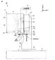
図1は、この発明の実施の形態1における工作機械を示す正面図である。図1を参照して、工作機械10は、立形マシニングセンタである。工作機械10は、ベッド12と、コラム13と、主軸頭41と、テーブル16と、工具マガジン21と、工具交換部31とを有する。(Embodiment 1)
1 is a front view showing a machine tool according to a first embodiment of the present invention. Referring to FIG. 1,
ベッド12は、コラム13、主軸頭41およびテーブル16等を搭載するためのベース部材であり、工場などの据え付け面に設置されている。 The
ベッド12には、コラム13が立設されている。コラム13には、主軸頭41が取り付けられている。主軸頭41は、鉛直方向に平行なZ軸方向に沿ってスライド移動可能に設けられている。コラム13および主軸頭41には、主軸頭41のZ軸方向へのスライド移動を可能とするための送り機構、案内機構、および、駆動源としてのサーボモータなどが適宜、設けられている。 A
主軸頭41は、主軸筒42と、主軸43とを有する。主軸筒42は、Z軸方向に沿って筒状に延びる形状を有する。主軸43は、主軸筒42により回転可能に支持されている。主軸43は、モータ駆動により、Z軸に平行な中心軸101を中心に回転する。主軸43には、加工対象であるワークを加工するための工具200が装着される。主軸43は、工具200を装着可能な工具装着部として設けられている。 The
テーブル16は、ワークを固定するための装置である。テーブル16は、サドル(不図示)を介して、ベッド12に取り付けられている。 The table 16 is a device for fixing the work. The table 16 is attached to the
サドルは、ベッド12に対して、水平方向に平行であり、Z軸方向に直交するY軸方向(前後方向)にスライド移動可能に設けられている。テーブル16は、サドルに対して、水平方向に平行であり、Z軸およびY軸に直交するX軸方向(左右方向)にスライド移動可能に設けられている。ベッド12、サドルおよびテーブル16には、サドルのY軸方向へのスライド移動およびテーブル16のX軸方向へのスライド移動を可能とするための送り機構、案内機構、および、駆動源としてのサーボモータなどが適宜、設けられている。 The saddle is parallel to the
工具マガジン21は、加工目的に応じて工具を順次、加工エリアに供給するため、複数の工具を格納する装置である。工具マガジン21には、主軸43に装着されるドリルやエンドミル、フライス等の工具200が格納されている。 The
工具マガジン21は、複数の工具ポット22と、支持プレート23と、カバー体24とを有する。 The
複数の工具ポット22の各々には、工具200が着脱可能に保持されている。支持プレート23は、複数の工具ポット22を、環状の搬送経路に沿って一定間隔で支持している。カバー体24は、複数の工具ポット22と、支持プレート23とを取り囲むように設けられている。カバー体24には、開口部25が設けられている。支持プレート23が回転駆動されることにより、工具ポット22が周方向に搬送される。 The
工具交換部31は、自動工具交換装置(ATC:Automatic Tool Changer)である。工具交換部31は、工具200を把持しながら、主軸43に装着される工具200を交換する。工具交換部31は、主軸43と、工具マガジン21(工具ポット22)との間で工具200を交換する。 The
工具交換部31は、工具交換アーム32と、進退用サーボモータ33と、回転用サーボモータ34とを有する。 The
進退用サーボモータ33および回転用サーボモータ34は、工具交換アーム32を駆動させるための装置である。進退用サーボモータ33の出力軸は、回転運動を直線運動に変換する運動変換機構(不図示)を介して、工具交換アーム32に接続されている。進退用サーボモータ33からの動力が工具交換アーム32に伝達されることにより、工具交換アーム32は、Z軸に平行な中心軸102に沿ってスライド移動する(上昇、下降する)。回転用サーボモータ34の出力軸は、動力伝達機構(不図示)を介して工具交換アーム32に接続されている。回転用サーボモータ34からの動力が工具交換アーム32に伝達されることにより、工具交換アーム32は、中心軸102を中心に旋回する。 The advancing / retreating
工具交換アーム32は、その構成部位として、把持部32pおよび把持部32qを有する。把持部32pおよび把持部32qは、中心軸102を挟んで対称に設けられている。工具交換アーム32は、把持部32pおよび把持部32qの間でアーム状に延びる形状を有する。把持部32pおよび把持部32qの各々は、工具200を把持可能に構成されている。工具交換アーム32は、2本の工具200を同時に把持することが可能なダブルアームタイプである。 The
自動工具交換時、工具交換アーム32が下降することにより、工具交換アーム32に把持された工具200が、主軸43および工具ポット22から抜き出される。工具交換アーム32が180°旋回することにより、工具交換アーム32の把持部32pに把持された工具200の位置と、工具交換アーム32の把持部32qに把持された工具200の位置とが、入れ替わる。工具交換アーム32が上昇することにより、工具交換アーム32に把持された工具200が、主軸43および工具ポット22に挿入される。 At the time of automatic tool exchange, the
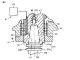
図2は、図1中の主軸頭の主軸端面側を示す断面図である。図1および図2を参照して、主軸43は、複数のベアリング46によって、主軸筒42に回転可能に支持されている。図2中において、主軸43には、工具200がクランプ状態で装着されている。 FIG. 2 is a sectional view showing a spindle end surface side of the spindle head in FIG. With reference to FIGS. 1 and 2, the
主軸43は、工具挿入部44を有する。工具挿入部44は、後述する工具200のシャンク部201(シャンクテーパ部201s)が挿入される開口形状をなしている。工具挿入部44は、加工エリア内で開口する開口面を有し、その開口面から中心軸101の軸方向に沿って筒状に延びる開口形状をなしている。工具挿入部44は、下方を向いて開口している。 The
工具挿入部44は、拘束面45を有する。拘束面45は、中心軸101を中心にしてその軸方向に沿って延びる円筒形の内周面からなる。拘束面45は、中心軸101の軸方向に沿って直径が変化するテーパ形状を有する。 The
主軸43は、ツールクランプ装置48をさらに有する。ツールクランプ装置48は、主軸43に工具200をクランプ可能なように構成されている。ツールクランプ装置48をクランプ動作させることによって、工具200が主軸43にクランプされ、ツールクランプ装置48をアンクランプ動作させることによって、工具200が主軸43からアンクランプされる。 The
一例として、工具200を把持可能なコレットと、中心軸101の軸方向に沿って前後移動することによって、コレットを開閉動作させるドローバーと、ドローバーに嵌装される皿バネと、ドローバーに油圧を作用させる油圧機構とを有するツールクランプ装置48が用いられている。この場合に、皿バネのバネ力によって工具200をクランプ力を得て、油圧機構で発生する油圧によって工具200のアンクランプ力を得る。 As an example, a collet capable of gripping the
工具200は、シャンク部201と、プルスタッド部202と、刃部203とを有する。シャンク部201は、シャンクテーパ部201sと、シャンクフランジ部201tとから構成されている。 The
シャンクテーパ部201sは、中心軸101の軸方向に沿って直径が変化するテーパ形状を有する。シャンクテーパ部201sは、工具200のクランプ時に工具挿入部44の拘束面45と面接触する。これにより、工具200は、主軸43に対して面拘束される。シャンクフランジ部201tは、中心軸101の軸方向におけるシャンクテーパ部201sの一方端から鍔状に広がる形状を有する。シャンクフランジ部201tは、工具200の自動工具交換時に、工具交換アーム32の把持部32pおよび把持部32qにより把持される。 The
プルスタッド部202は、中心軸101の軸方向におけるシャンクテーパ部201sの他方端に接続されている。プルスタッド部202は、工具200のクランプ時に、ツールクランプ装置48(コレット)により中心軸101の軸方向に沿って主軸43内に引っ張られる。 The
工作機械10は、コンピュータによる数値制御によって、ワーク加工のための各種動作が自動化されたNC(Numerically Control)工作機械である。 The
工作機械10は、制御装置51をさらに有する。制御装置51は、工作機械10に備え付けられ、工作機械10における各種動作を制御するための制御盤である。制御装置51は、たとえば、直交3軸(X軸、Y軸、Z軸)における各種構造体のスライド移動や、工具マガジン21および工具交換部31の動作、後述する空気供給部61によるエアパージ動作を制御する。 The
図3および図4は、自動工具交換時の工具に対するエアパージ工程を示す断面図である。図3および図4中には、図2中の2点鎖線IIIで囲まれた範囲が拡大して示されている。 3 and 4 are cross-sectional views showing an air purging process for a tool at the time of automatic tool change. In FIGS. 3 and 4, the range surrounded by the chain double-dashed line III in FIG. 2 is shown enlarged.
図1から図4を参照して、工作機械10は、空気供給部61をさらに有する。空気供給部61は、工具自動交換時に、主軸43の工具挿入部44と、工具200のシャンク部201との間の隙間210に空気を供給可能に構成されている。 With reference to FIGS. 1 to 4, the
空気供給部61は、エアコンプレッサ63と、空気流通孔62と、バルブ(不図示)とを有する。空気流通孔62は、主軸43に設けられている。空気流通孔62は、拘束面45に開口している。空気流通孔62は、拘束面45の複数個所に開口してもよい。エアコンプレッサ63は、圧縮空気を供給可能に構成されている。空気流通孔62には、エアコンプレッサ63からの空気が供給される。バルブは、エアコンプレッサ63から供給される空気の経路上に設けられている。 The
バルブが開状態とされると、空気流通孔62から隙間210に向けて空気が噴射される。空気が主軸端面側に向けて隙間210を通過することにより、工具200に付着した切屑が除去される。バルブが閉状態にされると、空気流通孔62から隙間210に向けた空気の噴射が停止する。 When the valve is opened, air is ejected from the
図5は、自動工具交換およびエアパージの工程の流れを示すフローチャート図である。図6は、自動工具交換時における工具交換アームの動き(進退運動,旋回運動)を示すグラフである。図7は、自動工具交換時における工具の速度変化を示すグラフである。図7中では、上昇時における工具200の速度がマイナスで示され、下降時における工具200の速度がプラスで示されている。 FIG. 5 is a flow chart showing the flow of steps of automatic tool replacement and air purging. FIG. 6 is a graph showing the movement (advancing and retracting movement, turning movement) of the tool changing arm during automatic tool changing. FIG. 7 is a graph showing changes in tool speed during automatic tool change. In FIG. 7, the speed of the
図1から図7を参照して、主軸43に装着される工具200の自動工具交換の工程と、その自動工具交換に伴って主軸43にて実行される工具200に対するエアパージ工程とについて説明する。 With reference to FIGS. 1 to 7, an automatic tool changing process of the
まず、図5中のS101のステップにおいて、工具マガジン21内の工具200を、待機位置まで移動させるとともに、主軸43を工具交換位置まで移動させる。 First, in step S101 in FIG. 5, the
工具マガジン21において、次のワーク加工に用いられる工具200Kを装着する工具ポット22を、カバー体24に設けられた開口部25の位置(割り出し位置)まで搬送する。工具ポット22を、図示しない旋回機構により90°旋回させることにより、割り出し位置から待機位置に移動させる。工具ポット22が待機位置にある時、工具ポット22に保持された工具200Kの中心軸が、中心軸101および中心軸102と平行な方向(Z軸方向)となる。 In the
工具200Jが装着された主軸43を、工具200Jを用いたワーク加工が完了した後、上記の工具ポット22の待機位置と隣り合う工具交換位置まで移動させる。 After the machining of the work using the
次に、図5中のS102のステップにおいて、加工エリア内と加工エリア外とを遮蔽するシャッター(不図示)を開いた状態で、工具交換アーム32を原位置(工具交換アーム32が、Y軸方向に沿ってアーム状に延びる位置)から90°旋回させる。 Next, in step S102 in FIG. 5, with the shutter (not shown) that shields the inside and the outside of the processing area opened, the
このとき、把持部32pが、主軸43に装着された工具200Jを把持し、把持部32qが、待機位置にある工具ポット22に保持された工具200Kを把持する(図1に示す状態)。工具200Jが把持部32pにより把持されたタイミングで、主軸43における工具200Jのクランプを解除する。 At this time, the
次に、図5中のS103のステップにおいて、工具交換アーム32を下降させるとともに、工具交換アーム32を180°旋回運動させる(図6中の位置A→位置Bに対応)。 Next, in step S103 in FIG. 5, the
これにより、主軸43から工具200Jを抜き出し、工具ポット22から工具200Kを抜き出すとともに、工具200JをZ軸方向において工具ポット22と対向する位置まで移動させ、工具200KをZ軸方向において主軸43と対向する位置まで移動させる。 As a result, the
次に、図5中のS104のステップにおいて、工具交換アーム32を上昇させて、エアブロー下端位置まで移動させる(図6中の位置B→位置C、図7中の時間t1→時間t2に対応)。 Next, in step S104 in FIG. 5, the
この際、工具交換アーム32を、V2の速度により移動させる。図3中には、工具交換アーム32をエアブロー下端位置(図6中の位置C)まで移動させた時の工具200が示されている。工具200のシャンクテーパ部201sは、工具挿入部44に挿入されている。シャンクテーパ部201sと、工具挿入部44の拘束面45との間には、隙間210(210C)が設けられている。隙間210(210C)には、空気流通孔62を通じて空気が噴射されている。 At this time, the
次に、図5中のS105のステップにおいて、工具交換アーム32を上昇させて、エアブロー上端位置まで移動させる(図6中の位置C→位置D、図7中の時間t2→時間t3に対応)。 Next, in step S105 in FIG. 5, the
この際、工具交換アーム32を、先のステップのV2よりも低速のV1の速度により移動させる。図4中には、工具交換アーム32をエアブロー上端位置(図6中の位置D)まで移動させた時の工具200が示されている。シャンクテーパ部201sと、工具挿入部44の拘束面45との間には、隙間210(210D)が設けられている。 At this time, the
隙間210は、中心軸101に直交する平面により切断された場合に、中心軸101を中心とするリング形状をなしている。隙間210は、中心軸101の半径方向におけるリング幅が一定となるリング形状をなしている。 The
図3および図4に示されるように、隙間210Dの大きさは、隙間210Cの大きさよりも小さい。中心軸101に直交する任意の平面220により切断された場合に得られる隙間210Dの面積は、同じ平面220により切断された場合に得られる隙間210Cの面積よりも小さい。平面220上において、中心軸101の半径方向における隙間210Dの長さ(リング幅)R1は、中心軸101の半径方向における隙間210Cの長さ(リング幅)R2よりも小さい。 As shown in FIGS. 3 and 4, the size of the gap 210D is smaller than the size of the
次に、図5中のS106のステップにおいて、工具交換アーム32をエアブロー上端位置にて一定時間だけ停止させる(図7中の時間t3→時間t4に対応)。 Next, in step S106 in FIG. 5, the
次に、図5中のS107のステップにおいて、工具交換アーム32を、エアブロー上端位置と、エアブロー下端位置との間で繰り返し上昇、下降させる(図6中の位置D→位置C→位置D→位置C→…、図7中の時間t4〜時間t9に対応)。 Next, in step S107 in FIG. 5, the
この際、工具交換アーム32を、V1の速度により、繰り返し上昇、下降させる。工具挿入部44に工具200Kのシャンク部201が挿入され、工具挿入部44と、工具200Kのシャンク部201との間に隙間210が設けられた状態において、工具200Kが、工具挿入部44に対してZ軸方向に沿って往復移動する。 At this time, the
上記ステップにおいて、工具200KがZ軸方向において微小に振動する現象が得られるように、エアブロー上端位置(位置D)と、エアブロー下端位置(位置C)との間の距離、および、工具200Kを往復移動させる周期が設定されることが好ましい。 In the above step, the distance between the air blow upper end position (position D) and the air blow lower end position (position C) and the
エアブロー上端位置(位置D)と、エアブロー下端位置(位置C)との間の距離は、特に限定されないが、たとえば、0.5mm以上5mm以下の範囲であってもよいし、1mm以上3mm以下の範囲であってもよい。 The distance between the air blow upper end position (position D) and the air blow lower end position (position C) is not particularly limited, but may be, for example, in the range of 0.5 mm or more and 5 mm or less, or 1 mm or more and 3 mm or less. It may be a range.
次に、図5中のS108のステップにおいて、工具交換アーム32をエアブロー上端位置にて一定時間だけ停止させる(図7中の時間t9→時間t10に対応)。 Next, in step S108 in FIG. 5, the
次に、図5中のS109のステップにおいて、工具交換アーム32を上昇させて、挿入完了位置まで移動させる(図6中の位置D→位置E、図7中の時間t10→時間t11に対応)。この際、工具交換アーム32を、V1の速度により上昇させる。主軸43において工具200Kをクランプする。 Next, in step S109 in FIG. 5, the
次に、図5中のS110のステップにおいて、工具交換アーム32を90°旋回させて、原位置に戻す。以上の工程により、主軸43に装着される工具200の自動工具交換が完了する。 Next, in step S110 in FIG. 5, the
本実施の形態における工作機械10では、制御装置51が、工具挿入部44に工具200のシャンク部201を挿入しつつ、工具挿入部44と、工具200のシャンク部201との間に隙間210を設けた状態において、工具200が工具挿入部44に対して所定方向に沿って往復移動するように、工具交換部31の駆動を制御する。 In the
このような構成によれば、工具200の往復運動に伴って隙間210の大きさが増減を繰り返すことによって、隙間210における空気流れの速度が刻々と変化する。これにより、隙間210における空気流れに乱れを生じさせて、工具200に付着した切屑を効率的に除去することができる。 With such a configuration, the size of the
また、工具200が工具挿入部44に対して往復運動する所定方向は、工具挿入部44に対する工具200のシャンク部201の挿入方向(Z軸方向)である。 The predetermined direction in which the
このような構成によれば、中心軸101の半径方向における隙間210の長さ(リング幅)が、中心軸101を中心とする周方向において均一となるため、工具挿入部44の拘束面45と、工具200のシャンクテーパ部201sとが、相互に干渉し難くなる。また、工具200に付着した切屑を効率的に除去する効果を、中心軸101を中心とする周方向においてばらつきなく奏することができる。 According to such a configuration, the length (ring width) of the
また、制御装置51は、工具挿入部44に対して工具200のシャンク部201を一方向に挿入するとともに、工具挿入部44と、工具200のシャンク部201との間に隙間210が生じる第1位置(図6中の位置D)にて、工具挿入部44に対する工具200のシャンク部201の挿入を停止させるステップ(S105に対応)と、第1位置(図6中の位置D)と、第1位置(図6中の位置D)から見て、工具200のシャンク部201の挿入方向とは反対方向に位置する第2位置(図6中の位置C)との間で、工具200を工具挿入部44に対して往復移動させるステップ(S107に対応)とを実行するように、工具交換部31の駆動を制御する。 In addition, the
このような構成によれば、S105のステップにて、工具挿入部44を隙間210が生じる第1位置に停止させてから、S107のステップにて、第1位置と、第1位置から見て隙間210が大きくなる方向にある第2位置との間で工具200を往復移動させる。このため、工具挿入部44の拘束面45と、工具200のシャンクテーパ部201sとが、相互にさらに干渉し難くなる。 With such a configuration, in step S105, the
なお、S107のステップにおいて、工具200を工具挿入部44に対して往復移動させる際に、主軸43(主軸頭41)を上昇、下降させてもよい。また、工具交換アーム32の上昇および下降と、主軸43(主軸頭41)の上昇および下降とを同時に実行することにより、工具200および工具挿入部44を相互に上下方向に沿って往復移動させてもよい。 In step S107, the spindle 43 (spindle head 41) may be raised or lowered when the
本発明が適用される工作機械は、立形マシニングセンタに限られず、たとえば、横形マシニングセンタ、または、旋削機能とミーリング機能とを有する複合加工機であってもよい。 The machine tool to which the present invention is applied is not limited to the vertical machining center, and may be, for example, a horizontal machining center or a multi-tasking machine having a turning function and a milling function.
(実施の形態2)
本実施の形態では、図5中のS107のステップにおいて、工具200および工具挿入部44を相互に往復移動させる形態の各種変形例について説明する。(Embodiment 2)
In the present embodiment, various modifications of the mode in which the
図8は、工具および工具挿入部を相互に往復移動させる形態の第1変形例を示す断面図である。図8中には、中心軸101に直交する平面により切断された主軸頭41の断面が模式的に示されている。 FIG. 8: is sectional drawing which shows the 1st modification of the form which reciprocates a tool and a tool insertion part mutually. In FIG. 8, a cross section of the
図1および図8を参照して、図5中のS107のステップにおいて、工具交換アーム32を、中心軸102を中心とする順方向および逆方向に交互に旋回させる。これにより、工具200を、工具挿入部44に対して、工具中心位置Pと工具中心位置Qとの間で、中心軸102を中心とする周方向に沿って往復移動させる。 With reference to FIGS. 1 and 8, in step S107 in FIG. 5, the
図9は、工具および工具挿入部を相互に往復移動させる形態の第2変形例を示す断面図である。図9中には、中心軸101に直交する平面により切断された主軸頭41の断面が模式的に示されている。なお、本変形例では、主軸頭41が、水平面(X軸−Y軸平面)内において移動可能に構成されているものとする。 FIG. 9: is sectional drawing which shows the 2nd modification of the form which reciprocates a tool and a tool insertion part mutually. In FIG. 9, a cross section of the
図1および図9を参照して、図5中のS107のステップにおいて、主軸43(主軸頭41)を、水平面(X軸−Y軸平面)内において、工具200の工具中心Pを中心にして円周を描くように移動させる。これにより、工具挿入部44を、工具200に対して、主軸中心位置101Aと主軸中心位置101Bとの間で、工具中心Pを中心する周方向に沿って往復運動させる。 1 and 9, in step S107 in FIG. 5, the spindle 43 (spindle head 41) is centered on the tool center P of the
図8および図9中に示す変形例においては、工具200および工具挿入部44が相互に往復運動する所定方向が、工具挿入部44に対する工具200のシャンク部201の挿入方向に直交する平面(X軸−Y軸平面)に平行な方向である。 In the modification shown in FIGS. 8 and 9, the predetermined direction in which the
このように構成された、この発明の実施の形態2における工作機械によれば、実施の形態1に記載の効果を同様に奏することができる。 According to the machine tool of the second embodiment of the present invention configured in this manner, the effects described in the first embodiment can be similarly obtained.
今回開示された実施の形態はすべての点で例示であって制限的なものではないと考えられるべきである。本発明の範囲は上記した説明ではなくて特許請求の範囲によって示され、特許請求の範囲と均等の意味および範囲内でのすべての変更が含まれることが意図される。 The embodiments disclosed this time are to be considered as illustrative in all points and not restrictive. The scope of the present invention is shown not by the above description but by the claims, and is intended to include meanings equivalent to the claims and all modifications within the scope.
この発明は、自動工具交換時の工具に対するエアパージ機構を備えた工作機械に適用される。 INDUSTRIAL APPLICABILITY The present invention is applied to a machine tool provided with an air purging mechanism for tools during automatic tool change.
10 工作機械、12 ベッド、13 コラム、16 テーブル、21 工具マガジン、22 工具ポット、23 支持プレート、24 カバー体、25 開口部、31 工具交換部、32 工具交換アーム、32p,32q 把持部、33 進退用サーボモータ、34 回転用サーボモータ、41 主軸頭、42 主軸筒、43 主軸、44 工具挿入部、45 拘束面、46 ベアリング、48 ツールクランプ装置、51 制御装置、61 空気供給部、62 空気流通孔、63 エアコンプレッサ、101,102 中心軸、101A,101B 主軸中心位置、200,200J,200K 工具、201 シャンク部、201s シャンクテーパ部、201t シャンクフランジ部、202 プルスタッド部、203 刃部、210,210C,210D 隙間、220 平面。 10 machine tools, 12 beds, 13 columns, 16 tables, 21 tool magazines, 22 tool pots, 23 support plates, 24 cover bodies, 25 openings, 31 tool changing parts, 32 tool changing arms, 32p, 32q gripping parts, 33 Advance / retreat servo motor, 34 rotation servo motor, 41 spindle head, 42 spindle cylinder, 43 spindle, 44 tool insertion part, 45 restraining surface, 46 bearing, 48 tool clamp device, 51 control device, 61 air supply part, 62 air Circulation hole, 63 air compressor, 101, 102 center axis, 101A, 101B main shaft center position, 200, 200J, 200K tool, 201 shank part, 201s shank taper part, 201t shank flange part, 202 pull stud part, 203 blade part, 210, 210C, 210 Gap, 220 plane.
Claims (4)
Translated fromJapanese工具を把持しながら、前記工具装着部に装着される工具を交換する工具交換部と、
前記工具交換部による工具の交換時に、前記工具挿入部と、工具のシャンク部との間の隙間に空気を供給可能に構成される空気供給部と、
前記工具挿入部に工具のシャンク部を挿入しつつ、前記工具挿入部と、工具のシャンク部との間に隙間を設けた状態において、工具および前記工具挿入部が相互に所定方向に沿って往復移動するように、前記工具装着部および前記工具交換部の少なくともいずれか一方の駆動を制御する制御装置とを備え、
前記工具挿入部には、工具のシャンク部が一方向から挿入され、
前記工具装着部は、工具のシャンク部が前記工具挿入部の所定位置まで挿入された場合に、工具をクランプするツールクランプ装置をさらに有し、
工具および前記工具挿入部が相互に往復移動する間、工具のシャンク部は、前記所定位置から、工具のシャンク部の挿入方向とは反対方向に離れた位置に配置される、工作機械。A tool mounting portion having a tool insertion portion having an opening shape into which the shank portion of the tool is inserted, and a tool mounting portion capable of mounting a tool,
A tool exchanging section for exchanging the tool mounted on the tool mounting section while gripping the tool,
At the time of exchanging the tool by the tool exchanging part, an air supply part configured to be able to supply air to the gap between the tool insertion part and the shank part of the tool,
While inserting the shank portion of the tool into the tool insertion portion, with the gap provided between the tool insertion portion and the shank portion of the tool, the tool and the tool insertion portion reciprocate along a predetermined direction. A control device that controls driving of at least one of the tool mounting portion and the tool exchange portion so as to move,
In the tool insertion portion, the shank portion of the tool is inserted from one direction,
The tool mounting portion further has a tool clamp device for clamping the tool when the shank portion of the tool is inserted to a predetermined position of the tool insertion portion,
The machine tool, wherein the shank portion of the tool is arranged at a position away from the predetermined position in a direction opposite to the insertion direction of the shank portion of the tool while the tool and the tool insertion portion reciprocate with respect to each other .
前記工具挿入部に対して工具のシャンク部を一方向に挿入するとともに、前記工具挿入部と、工具のシャンク部との間に隙間が生じる第1位置にて、前記工具挿入部に対する工具のシャンク部の挿入を停止させるステップと、
前記第1位置と、前記第1位置から見て、工具のシャンク部の挿入方向とは反対方向に位置する第2位置との間で、工具および前記工具挿入部を相互に往復移動させるステップと、を実行するように、前記工具装着部および前記工具交換部の少なくともいずれか一方の駆動を制御する、請求項2に記載の工作機械。The control device is
The shank part of the tool is inserted into the tool insertion part in one direction, and the shank of the tool with respect to the tool insertion part is located at a first position where a gap is created between the tool insertion part and the shank part of the tool. The step of stopping the insertion of the part,
Reciprocatingly moving the tool and the tool insertion portion to and from each other between the first position and a second position that is located in a direction opposite to the insertion direction of the shank portion of the tool when viewed from the first position; The machine tool according to claim 2, wherein driving of at least one of the tool mounting portion and the tool exchanging portion is controlled so as to execute the.
Priority Applications (4)
| Application Number | Priority Date | Filing Date | Title |
|---|---|---|---|
| JP2018072333AJP6688829B2 (en) | 2018-04-04 | 2018-04-04 | Machine Tools |
| US16/365,838US10792735B2 (en) | 2018-04-04 | 2019-03-27 | Machine tool |
| EP19166844.1AEP3549716B1 (en) | 2018-04-04 | 2019-04-02 | Machine tool |
| CN201910267046.2ACN110340721B (en) | 2018-04-04 | 2019-04-03 | machine tool |
Applications Claiming Priority (1)
| Application Number | Priority Date | Filing Date | Title |
|---|---|---|---|
| JP2018072333AJP6688829B2 (en) | 2018-04-04 | 2018-04-04 | Machine Tools |
Publications (2)
| Publication Number | Publication Date |
|---|---|
| JP2019181590A JP2019181590A (en) | 2019-10-24 |
| JP6688829B2true JP6688829B2 (en) | 2020-04-28 |
Family
ID=66223609
Family Applications (1)
| Application Number | Title | Priority Date | Filing Date |
|---|---|---|---|
| JP2018072333AActiveJP6688829B2 (en) | 2018-04-04 | 2018-04-04 | Machine Tools |
Country Status (4)
| Country | Link |
|---|---|
| US (1) | US10792735B2 (en) |
| EP (1) | EP3549716B1 (en) |
| JP (1) | JP6688829B2 (en) |
| CN (1) | CN110340721B (en) |
Families Citing this family (3)
| Publication number | Priority date | Publication date | Assignee | Title |
|---|---|---|---|---|
| JP6737847B2 (en)* | 2018-07-31 | 2020-08-12 | ファナック株式会社 | Spindle device |
| JP6998288B2 (en)* | 2018-10-31 | 2022-01-18 | 日精ホンママシナリー株式会社 | Spindle for rotary tools with tool seating confirmation function |
| CN113894299B (en)* | 2021-09-30 | 2022-12-06 | 珠海格力电器股份有限公司 | Main shaft gas cleaning device |
Family Cites Families (29)
| Publication number | Priority date | Publication date | Assignee | Title |
|---|---|---|---|---|
| DE2754636A1 (en)* | 1977-12-08 | 1979-06-13 | Droop & Rein | Endless tool magazine for machine tool - has tapered shanks of cutting tools cleaned by blast of air through perforations in conical wall |
| JPS60172B2 (en)* | 1981-12-21 | 1985-01-07 | 東芝機械株式会社 | Main spindle structure of vertical lathe |
| US4504824A (en)* | 1982-11-17 | 1985-03-12 | Houdaille Industries, Inc. | Tool detection system |
| DE3930070C2 (en)* | 1989-09-09 | 1993-12-16 | Chiron Werke Gmbh | Machine tool with blow-out tool holder |
| JP2852561B2 (en)* | 1990-10-24 | 1999-02-03 | 株式会社森精機製作所 | Tool holder of spindle unit with automatic tool changer |
| JPH0529656U (en)* | 1991-09-30 | 1993-04-20 | 豊田工機株式会社 | Machine tool tool for removing chips from spindle |
| JPH07285046A (en)* | 1994-04-19 | 1995-10-31 | Hitachi Seiki Co Ltd | Tool mounting method and machine tool for machine tool |
| JPH0957582A (en)* | 1995-08-11 | 1997-03-04 | Kitamura Mach Co Ltd | Main spindle device |
| JPH1190762A (en)* | 1997-05-27 | 1999-04-06 | Chiron Werke Gmbh & Co Kg | Machine tool |
| JPH11138382A (en)* | 1997-11-12 | 1999-05-25 | Okuma Corp | Main spindle device |
| JP3055019B1 (en)* | 1999-02-22 | 2000-06-19 | ホーコス株式会社 | Chip suction type machine tool |
| JP2000308935A (en)* | 1999-04-28 | 2000-11-07 | Howa Mach Ltd | Tool replacing device and device and machine tool |
| TW431251U (en)* | 2000-01-29 | 2001-04-21 | Sun Ho Wei | Automatic blowing device for spindle releasing and holding cutting tools of cutting machine center |
| US20020045521A1 (en)* | 2000-10-16 | 2002-04-18 | Hideki Mochida | Spindle unit for a machine tool |
| US6939094B2 (en)* | 2003-01-28 | 2005-09-06 | Macro Technologies Inc. | Autonomous power interface for modifying limited rotation speed of a machine |
| JP3764432B2 (en) | 2003-03-06 | 2006-04-05 | ファナック株式会社 | Tool chip prevention / removal method and tool changer |
| JP2005081489A (en)* | 2003-09-08 | 2005-03-31 | Nippei Toyama Corp | Cleaning method and device of tool holder fitting part of spindle device in machine tool |
| JP3883996B2 (en)* | 2003-09-30 | 2007-02-21 | 三洋化成工業株式会社 | Flame retardant for polyester synthetic fiber |
| US7568867B2 (en)* | 2006-10-18 | 2009-08-04 | Bryan Steve M | Air driven spindle assembly |
| JP4764450B2 (en)* | 2008-03-31 | 2011-09-07 | 三菱重工業株式会社 | Tool contact state detection device for machine tools |
| JP2010105088A (en)* | 2008-10-29 | 2010-05-13 | Mazda Motor Corp | Device for removing swarf from machine tool |
| MX2012005655A (en)* | 2009-11-18 | 2012-08-08 | Komatsu Ntc Ltd | Tool magazine and machining center. |
| US9162335B2 (en)* | 2012-01-20 | 2015-10-20 | Air Turbine Technology, Inc. | Auto changer spindle mounting assembly |
| US9375816B2 (en)* | 2012-07-11 | 2016-06-28 | Air Turbine Technology, Inc. | Auto changer spindle mounting assembly adapted to drill tap machines |
| JP6314066B2 (en)* | 2014-09-08 | 2018-04-18 | Dmg森精機株式会社 | Machine Tools |
| JP3198538U (en)* | 2015-04-17 | 2015-07-09 | 株式会社アーレスティ | Blade tool gripping device |
| JP6306617B2 (en)* | 2016-01-05 | 2018-04-04 | ファナック株式会社 | Machine tool with chip discharge device |
| CN206643615U (en)* | 2016-12-13 | 2017-11-17 | 宁波海天精工股份有限公司 | A kind of function switching structure for being applied to main shaft tool changing air blowing and central water outlet |
| JP6297128B1 (en)* | 2016-12-16 | 2018-03-20 | Dmg森精機株式会社 | Machine Tools |
- 2018
- 2018-04-04JPJP2018072333Apatent/JP6688829B2/enactiveActive
- 2019
- 2019-03-27USUS16/365,838patent/US10792735B2/enactiveActive
- 2019-04-02EPEP19166844.1Apatent/EP3549716B1/enactiveActive
- 2019-04-03CNCN201910267046.2Apatent/CN110340721B/enactiveActive
Also Published As
| Publication number | Publication date |
|---|---|
| EP3549716A1 (en) | 2019-10-09 |
| CN110340721B (en) | 2022-03-15 |
| JP2019181590A (en) | 2019-10-24 |
| EP3549716B1 (en) | 2021-01-27 |
| US20190308251A1 (en) | 2019-10-10 |
| US10792735B2 (en) | 2020-10-06 |
| CN110340721A (en) | 2019-10-18 |
Similar Documents
| Publication | Publication Date | Title |
|---|---|---|
| JP5026884B2 (en) | Machine tool with automatic tool changer | |
| JP5497582B2 (en) | Horizontal machining center | |
| JP6314066B2 (en) | Machine Tools | |
| CN108655802B (en) | Machine tool system and moving method | |
| CN205380492U (en) | Machine tool | |
| JP6688829B2 (en) | Machine Tools | |
| JP6917135B2 (en) | Machine Tools | |
| JP2016144853A (en) | Machine Tools | |
| TWI464024B (en) | Lathe device | |
| JP2019010726A (en) | Machine tool for machining workpiece | |
| JP5289910B2 (en) | Press machine | |
| EP1247611B1 (en) | A multi-axis work centre, for multiple production, in particular for wood working | |
| JP6209568B2 (en) | Machine Tools | |
| KR200393854Y1 (en) | Workpiece loading device for lathe | |
| KR100633571B1 (en) | Machining Center of Machining Center | |
| JP3780144B2 (en) | Work reversing device | |
| JPH0890302A (en) | Metal cutting machine tool | |
| KR20220124534A (en) | Apparatus for cutting inside of an object | |
| JP2005279835A (en) | Composite machining machine and turning method | |
| JP2017222018A (en) | Machine tool and machining method by machine tool | |
| CN113829065A (en) | Multi-task type work machine assembly | |
| JP2002011601A (en) | Lathe | |
| JPH0890303A (en) | Numerically controlled automatic lathe | |
| JP2551292B2 (en) | Cutting equipment | |
| JP4722636B2 (en) | Compound lathe tool changer |
Legal Events
| Date | Code | Title | Description |
|---|---|---|---|
| A621 | Written request for application examination | Free format text:JAPANESE INTERMEDIATE CODE: A621 Effective date:20190313 | |
| A131 | Notification of reasons for refusal | Free format text:JAPANESE INTERMEDIATE CODE: A131 Effective date:20200121 | |
| A521 | Request for written amendment filed | Free format text:JAPANESE INTERMEDIATE CODE: A523 Effective date:20200310 | |
| TRDD | Decision of grant or rejection written | ||
| A01 | Written decision to grant a patent or to grant a registration (utility model) | Free format text:JAPANESE INTERMEDIATE CODE: A01 Effective date:20200331 | |
| A61 | First payment of annual fees (during grant procedure) | Free format text:JAPANESE INTERMEDIATE CODE: A61 Effective date:20200406 | |
| R150 | Certificate of patent or registration of utility model | Ref document number:6688829 Country of ref document:JP Free format text:JAPANESE INTERMEDIATE CODE: R150 | |
| R250 | Receipt of annual fees | Free format text:JAPANESE INTERMEDIATE CODE: R250 |