JP6687495B2 - Component mounting line - Google Patents
Component mounting lineDownload PDFInfo
- Publication number
- JP6687495B2 JP6687495B2JP2016202405AJP2016202405AJP6687495B2JP 6687495 B2JP6687495 B2JP 6687495B2JP 2016202405 AJP2016202405 AJP 2016202405AJP 2016202405 AJP2016202405 AJP 2016202405AJP 6687495 B2JP6687495 B2JP 6687495B2
- Authority
- JP
- Japan
- Prior art keywords
- housing
- component mounting
- substrate
- reflow
- air
- Prior art date
- Legal status (The legal status is an assumption and is not a legal conclusion. Google has not performed a legal analysis and makes no representation as to the accuracy of the status listed.)
- Active
Links
- 239000000758substrateSubstances0.000claimsdescription61
- 229910000679solderInorganic materials0.000claimsdescription30
- 238000010438heat treatmentMethods0.000description20
- 238000001816coolingMethods0.000description15
- 238000007639printingMethods0.000description9
- 238000005192partitionMethods0.000description6
- 238000000034methodMethods0.000description5
- 239000000428dustSubstances0.000description4
- 238000011144upstream manufacturingMethods0.000description4
- 238000007664blowingMethods0.000description2
- 230000005611electricityEffects0.000description2
- 238000005516engineering processMethods0.000description2
- 230000003068static effectEffects0.000description2
- 238000010586diagramMethods0.000description1
- 239000000155meltSubstances0.000description1
- 238000012986modificationMethods0.000description1
- 230000004048modificationEffects0.000description1
- 238000005476solderingMethods0.000description1
Images


Landscapes
- Electric Connection Of Electric Components To Printed Circuits (AREA)
- Supply And Installment Of Electrical Components (AREA)
Description
Translated fromJapanese本明細書に開示する技術は、部品実装ラインに関する。 The technology disclosed in this specification relates to a component mounting line.
特許文献1には、ハウジングの内部において基板の上にはんだを介して電子部品を実装する部品実装装置が開示されている。 Patent Document 1 discloses a component mounting apparatus that mounts electronic components on a substrate inside a housing via solder.
部品実装装置では、装置内の各機器から生じる熱によって、ハウジングの内部の空気の温度が高くなることがある。例えば部品実装装置がヘッドを動かすためのXYロボットを備えている場合、XYロボットが動作したときに発生する熱によって、ハウジングの内部の空気の温度が高くなる。また、例えば部品実装装置がヘッドを動かすための駆動機構としてリニアモーターを備えている場合、リニアモーターが動作したときに発生する熱によって、ハウジングの内部の空気の温度が高くなる。特に近年では、多数の電子部品を素早く実装するために、ヘッドを高速で動かすことが求められている。しかしながら、ヘッドを高速で動かそうとすると、ヘッドを動かすためのXYロボットやリニアモーターの動作が高速になり、それらから発生する熱の量が更に多くなる。そうすると、ハウジングの内部の空気の温度が更に高くなる。 In the component mounting apparatus, the temperature of the air inside the housing may increase due to the heat generated from each device in the apparatus. For example, when the component mounting apparatus includes an XY robot for moving the head, the temperature of the air inside the housing rises due to the heat generated when the XY robot operates. Further, for example, when the component mounting apparatus includes a linear motor as a drive mechanism for moving the head, the temperature of the air inside the housing rises due to the heat generated when the linear motor operates. Particularly in recent years, it has been required to move the head at high speed in order to quickly mount a large number of electronic components. However, if an attempt is made to move the head at high speed, the operation of the XY robot or the linear motor for moving the head becomes faster, and the amount of heat generated from them increases further. Then, the temperature of the air inside the housing becomes higher.
また、ハウジングの内部の空気の温度が高くなると、それに伴ってハウジングの内部の空気の湿度が低くなり、その結果として、ハウジングの内部で静電気が発生し易くなる。ハウジングの内部で静電気が発生すると、電子部品が故障する原因になり得る。 Further, when the temperature of the air inside the housing becomes high, the humidity of the air inside the housing becomes low accordingly, and as a result, static electricity is easily generated inside the housing. The generation of static electricity inside the housing can cause electronic components to fail.
そこで、部品実装装置のハウジングの内部の空気をハウジングの外部に排気する方法が考えられる。例えば部品実装装置の周囲に空気を排気する方法が考えられる。しかしながら、この方法では、排気される高温の空気によって部品実装装置の周囲にいる作業者が不快感を覚えることがある。 Therefore, a method of exhausting the air inside the housing of the component mounting apparatus to the outside of the housing can be considered. For example, a method of exhausting air around the component mounting device can be considered. However, in this method, the worker who is around the component mounting apparatus may feel discomfort due to the exhausted high temperature air.
また、ハウジングの内部において電子部品を実装する部品実装装置では、ハウジングの内部の圧力を外部の圧力より高くすることがある。これによって、ハウジングの内部が正圧になり、ハウジングの外部からハウジングの内部に塵埃が入ることが抑制される。そのため、ハウジングの内部が清浄な状態に維持される。しかしながら、ハウジングの内部の圧力を外部の圧力より高くすると、ハウジングの内部の空気がハウジングの外部に流出することがある。ハウジングの内部の空気の温度が高い状態で、その空気がハウジングの外部に流出すると、部品実装装置の周囲にいる作業者が不快感を覚えることがある。そこで本明細書は、部品実装装置で生じる熱を有効に利用することができる技術を提供する。 Further, in a component mounting device that mounts electronic components inside the housing, the pressure inside the housing may be higher than the pressure outside. As a result, the inside of the housing has a positive pressure, and dust is suppressed from entering the inside of the housing from the outside of the housing. Therefore, the inside of the housing is maintained in a clean state. However, if the pressure inside the housing is made higher than the pressure outside, the air inside the housing may flow out to the outside of the housing. When the temperature of the air inside the housing is high and the air flows out of the housing, an operator around the component mounting apparatus may feel uncomfortable. Therefore, the present specification provides a technique capable of effectively utilizing the heat generated in the component mounting apparatus.
本明細書に開示する部品実装ラインは、第1ハウジングの内部において基板の上にはんだを介して電子部品を実装する部品実装装置と、基板の上に電子部品が実装された後に、基板と電子部品の間に介在しているはんだを第2ハウジングの内部においてリフローするリフロー装置と、前記部品実装装置と前記リフロー装置に接続されており、前記部品実装装置の前記第1ハウジングの内部の空気を前記リフロー装置の前記第2ハウジングの内部に送るダクトと、を備えている。 The component mounting line disclosed in the present specification includes a component mounting apparatus that mounts an electronic component on a substrate via solder inside a first housing, and a substrate mounting device that mounts an electronic component on the substrate and then mounts the electronic component on the substrate. A reflow device for reflowing the solder interposed between the components inside the second housing, and the component mounting device and the reflow device, which are connected to the air inside the first housing of the component mounting device. A duct for feeding the inside of the second housing of the reflow device.
このような構成では、基板の上に電子部品を実装するために部品実装装置が動作したときに装置内の各機器から生じる熱をリフロー装置に送ることによって、その熱をリフロー装置で有効に利用することができる。 In such a configuration, when the component mounting apparatus operates to mount electronic components on the board, heat generated by each device in the apparatus is sent to the reflow apparatus, so that the heat can be effectively used in the reflow apparatus. can do.
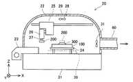
実施例に係る部品実装ラインについて図面を用いて説明する。図1に示すように、実施例に係る部品実装ライン1は、印刷装置90と部品実装装置20とリフロー装置40とダクト60を備えている。印刷装置90と部品実装装置20とリフロー装置40は並んで配置されている。ダクト60の一端部は部品実装装置20に接続されており、他端部はリフロー装置40に接続されている。ダクト60は、部品実装装置20からリフロー装置40まで延びている。 A component mounting line according to the embodiment will be described with reference to the drawings. As shown in FIG. 1, the component mounting line 1 according to the embodiment includes a
印刷装置90は、図2に示すように、電子部品200を実装するための基板100にはんだ300を印刷する装置である。印刷装置90は、ペースト状のはんだ300を基板100の上面にスクリーン印刷する。印刷装置90は、部品実装装置20よりも上流側に配置されている。印刷装置90によってはんだ300が印刷された基板100が、印刷装置90から部品実装装置20へ送られる。 As shown in FIG. 2, the
図3に示すように、部品実装装置20は、電子部品200を基板100に実装する装置である。部品実装装置20は、ベース21とハウジング22(第1ハウジングの一例)を備えている。ハウジング22は、ベース21の上に配置されており、ベース21を覆っている。部品実装装置20は、ハウジング22の内部において電子部品200を基板100に実装する。電子部品200は、上記の印刷装置90によって基板100に印刷されたはんだ300を介して、基板100の上に実装される。 As shown in FIG. 3, the
また、部品実装装置20は、フィーダー23とコンベア24を備えている。フィーダー23は、ハウジング22に対して着脱可能に構成されている。フィーダー23は、ハウジング22の前部に取り付けられる。フィーダー23は、ハウジング22に取り付けられた状態で、複数の電子部品200をハウジング22の内部に供給する。コンベア24は、ベース21の上に配置されている。コンベア24は、電子部品200を実装するための基板100を搬送する装置である。このコンベア24は、基板100をハウジング22の内部に搬入し、ハウジング22の内部において基板100を保持し、ハウジング22の外部に基板100を搬出する。コンベア24は、電子部品200を基板100に実装するときに基板100を保持している。ハウジング22の側面には、基板100の出入口39が形成されている。基板100の出入口39から基板100が搬入または搬出される。 The
また、部品実装装置20は、XYロボット25とヘッド26を備えている。XYロボット25とヘッド26は、ハウジング22の内部に配置されている。XYロボット25は、フィーダー23とコンベア24の上方において、ヘッド26をモーター駆動によってX方向とY方向に動かす装置である。ヘッド26を動かすための駆動機構としては、ヘッド26を高速で動かす観点から例えばリニアモーターを用いることが好ましい。ヘッド26は、フィーダー23とコンベア24の上方において両者の間を往復移動する。また、ヘッド26は、電子部品200を保持するためのノズル27を備えている。ヘッド26は、ノズル27をモーター駆動によってZ方向に動かすことができる。ノズル27は、フィーダー23によって供給された電子部品200を吸着して保持する。また、ノズル27は、保持した電子部品200を、コンベア24に保持されている基板100の上で解放して基板100に実装する。基板100に印刷されたはんだ300の上に電子部品200が配置される。 Further, the
また、部品実装装置20は、吸気ファン28とフィルタ29を備えている。吸気ファン28とフィルタ29は、ハウジング22の上部に取り付けられている。吸気ファン28は、ハウジング22の外部の空気をハウジング22の内部に吸気する装置である。吸気ファン28がハウジング22の外部の空気を内部に吸気することによって、ハウジング22の内部の圧力が外部の圧力よりも高くなる。吸気ファン28は、ハウジング22の内部の圧力を高める圧力装置の一例である。ハウジング22の内部の圧力を外部の圧力より高めることによって、ハウジング22の隙間を通じてハウジング22の外部から内部に塵埃が入ることが抑制される。例えば、ベース21とハウジング22の間の隙間やフィーダー23とハウジング22の間の隙間を通じてハウジング22の内部に塵埃が入ることが抑制される。吸気ファン28によって吸気される空気はフィルタ29を通過する。フィルタ29は、ハウジング22の外部から内部に吸気される空気に含まれている塵埃を捕集する。フィルタ29としては、例えば、HEPA(High Efficiency Particulate Air Filter)フィルタを用いることができる。 The
また、部品実装装置20は、排気ファン31を備えている。また、部品実装装置20には、ダクト60が接続されている。排気ファン31は、ハウジング22の後部に取り付けられている。ダクト60は、部品実装装置20のハウジング22の後部に固定されている。排気ファン31は、ダクト60と向かい合うように配置されている。排気ファン31は、ダクト60の開口部の正面に配置されている。排気ファン31は、ハウジング22の内部の空気をダクト60に排気する。部品実装装置20が動作する際に、部品実装装置20の各構成要素から熱が発生することがある。例えば、XYロボット25がヘッド26を動かす際に、XYロボット25から熱が発生することがある。あるいは、ヘッド26がノズル27を動かす際に、ノズル27から熱が発生することがある。このように、部品実装装置20の各構成要素から熱が発生することによって、ハウジング22の内部の空気の温度が上昇することがある。排気ファン31は、温度が上昇したハウジング22の内部の空気を排気する。 Further, the
図4に示すように、リフロー装置40は、基板100と電子部品200の間のはんだ300をリフローする装置である。リフロー装置40は、基板100と電子部品200をはんだ付けする装置である。リフロー装置40は、基板100と電子部品200の間に介在しているはんだ300を加熱して溶かし、溶かしたはんだ300を冷却して固めることによって基板100と電子部品200をはんだ付けする。 As shown in FIG. 4, the
リフロー装置40は、予熱ゾーン401と加熱ゾーン402と冷却ゾーン403を備えている。予熱ゾーン401と加熱ゾーン402と冷却ゾーン403は、基板100の搬送方向に並んで配置されている。予熱ゾーン401は、基板100の搬送方向の上流側に配置されている。予熱ゾーン401は、加熱ゾーン402よりも上流側に配置されている。加熱ゾーン402は、予熱ゾーン401と冷却ゾーン403の間に配置されている。加熱ゾーン402は、冷却ゾーン403よりも上流側に配置されている。冷却ゾーン403は、基板100の搬送方向の下流側に配置されている。予熱ゾーン401では、基板100と電子部品200の間のはんだ300が予熱される。加熱ゾーン402では、基板100と電子部品200の間のはんだ300が加熱される。冷却ゾーン403では、基板100と電子部品200の間のはんだ300が冷却される。 The
リフロー装置40は、コンベア41とハウジング42(第2ハウジングの一例)を備えている。コンベア41は、ハウジング42の内部に配置されている。コンベア41は、ハウジング42の入口426から出口424まで延びている。コンベア41は、ハウジング42の入口426から出口424まで基板100を搬送する装置である。ハウジング42の入口426からハウジング42の内部に基板100が搬入される。また、ハウジング42の出口424からハウジング42の外部に基板100が搬出される。 The
ハウジング42は、複数(2個)の仕切壁43を備えている。複数の仕切壁43は、基板100の搬送方向に並んでいる。複数の仕切壁43は、ハウジング42の内部の空間を基板100の搬送方向に仕切っている。複数の仕切壁43によってハウジング42の内部の空間が仕切られることによって、予熱ゾーン401と加熱ゾーン402と冷却ゾーン403が形成されている。 The
予熱ゾーン401は、ハウジング42の入口426側に形成されている。予熱ゾーン401におけるハウジング42の内部には、複数(2個)の予熱ヒーター411と複数(2個)の予熱ファン412が配置されている。コンベア41の上側と下側に、それぞれ予熱ヒーター411と予熱ファン412が配置されている。各予熱ヒーター411は、コンベア41によって搬送されている基板100を加熱する。各予熱ヒーター411は、後述する各加熱ヒーター421よりも低温で基板100を加熱する。各予熱ファン412は、基板100に向けて送風する。各予熱ファン412が送風することによって、各予熱ヒーター411の熱が基板100に送られる。 The preheating
加熱ゾーン402は、予熱ゾーン401よりもハウジング42の出口424側に形成されている。加熱ゾーン402におけるハウジング42の内部には、複数(2個)の加熱ヒーター421と複数(2個)の加熱ファン422が配置されている。コンベア41の上側と下側に、それぞれ加熱ヒーター421と加熱ファン422が配置されている。各加熱ヒーター421は、コンベア41によって搬送されている基板100を加熱する。各加熱ヒーター421は、上述した各予熱ヒーター411よりも高温で基板100を加熱する。各加熱ファン422は、基板100に向けて送風する。各加熱ファン422が送風することによって、各加熱ヒーター421の熱が基板100に送られる。 The
冷却ゾーン403は、加熱ゾーン402よりもハウジング42の出口424側に形成されている。冷却ゾーン403におけるハウジング42の内部には、複数(2個)の冷却器431と複数(2個)の冷却ファン432が配置されている。コンベア41の上側と下側に、それぞれ冷却器431と冷却ファン432が配置されている。各冷却器431は、コンベア41によって搬送されている基板100を冷却する。各冷却ファン432は、基板100に向けて送風する。各冷却ファン432が送風することによって、各冷却器431の冷気が基板100に送られる。 The
リフロー装置40には、ダクト60が接続されている。ダクト60は、リフロー装置40の予熱ゾーン401に接続されている。ダクト60は、予熱ゾーン401におけるハウジング42の前部に固定されている。ダクト60は、部品実装装置20のハウジング22の内部の空気をリフロー装置40のハウジング42の内部に送る。 A
以上の説明から明らかなように、実施例に係る部品実装ライン1は、ハウジング22の内部において基板100の上にはんだ300を介して電子部品200を実装する部品実装装置20と、部品実装装置20のハウジング22の内部の圧力を外部の圧力より高くする吸気ファン28と、部品実装装置20によって基板100の上に電子部品200が実装された後に、基板100と電子部品200の間に介在しているはんだ300をハウジング42の内部においてリフローするリフロー装置40と、部品実装装置20とリフロー装置40に接続されており、部品実装装置20のハウジング22の内部の空気をリフロー装置40のハウジング42の内部に送るダクト60と、を備えている。 As is apparent from the above description, the component mounting line 1 according to the embodiment includes the
このような構成では、基板100に電子部品200を実装するために部品実装装置20が動作すると、部品実装装置20の各機器から生じる熱によって、部品実装装置20のハウジング22の内部の空気の温度が高くなることがある。例えば、XYロボット25がヘッド26を動かす際に、XYロボット25から熱が発生し、その熱によってハウジング22の内部の空気の温度が高くなることがある。また、上記の構成では、吸気ファン28によってハウジング22の内部の圧力を外部の圧力より高くしているので、ハウジング22の内部の空気がハウジング22の隙間から外部に流出し易くなっている。例えば、ベース21とハウジング22の間の隙間やフィーダー23とハウジング22の間の隙間を通じて、ハウジング22の内部の空気が外部に流出し易くなっている。そのため、そのままにしておくと、ハウジング22の内部の高温の空気が外部に流出してしまい、流出した高温の空気によって部品実装装置20の周囲にいる作業者が不快感を覚える可能性がある。そこで、上記の構成では、ダクト60によって、部品実装装置20のハウジング22の内部の空気をリフロー装置40のハウジング42の内部に送るようにしている。リフロー装置40のハウジング42の内部では、基板100と電子部品200の間のはんだ300をリフローしている。リフロー装置40では高温ではんだ300をリフローする。そのため、部品実装装置20で生じた高温の空気をダクト60によってリフロー装置40に送ることにより、高温の空気をリフロー装置40で有効に利用することができる。 In such a configuration, when the
また、上記の部品実装ライン1では、リフロー装置40のハウジング42に入口426と出口424が形成されている。電子部品200が実装された後の基板100が入口426からハウジング42の内部に搬入される。また、はんだ300がリフローされた後の基板100が出口424から外部に搬出される。ダクト60は、リフロー装置40のハウジング42の出口424よりも入口426に近い位置に接続されている。 In the component mounting line 1 described above, an
このような構成によれば、リフロー装置40のハウジング42の入口426に近い部分に高温の空気を送ることができる。例えば、予熱ゾーン401におけるハウジング42の内部に高温の空気を送ることができる。そのため、リフロー装置40のハウジング42において比較的温度が低い部分に高温の空気を送ることができるので、部品実装装置20で生じる熱をより有効に利用することができる。 With such a configuration, high temperature air can be sent to a portion of the
また、ヘッド26を動かすための駆動機構としてリニアモーターを用いている場合は、高速動作によって熱が生じ易いので上記の構成が特に有効である。 Further, when a linear motor is used as a drive mechanism for moving the head 26, heat is likely to be generated by high-speed operation, so the above configuration is particularly effective.
また、上記の部品実装ライン1では、部品実装装置20によって電子部品200が実装された基板100がリフロー装置40に送られる。このような構成によれば、リフロー装置40に送られる基板100と空気が、同じ部品実装装置20に由来する。これによって、基板100に電子部品200を実装する際に、リフロー装置40に空気を送るための部品実装装置20が確実に動作するので、リフロー装置40に高温の空気を確実に送ることができる。また、部品実装装置20とリフロー装置40が繋がっているので、部品実装ライン1の構成を簡素にすることができる。 In the component mounting line 1 described above, the
以上、一実施例について説明したが、具体的な態様は上記実施例に限定されるものではない。以下の説明において、上述の説明における構成と同様の構成については、同一の符号を付して説明を省略する。 Although one embodiment has been described above, the specific mode is not limited to the above embodiment. In the following description, the same components as those in the above description will be designated by the same reference numerals and description thereof will be omitted.
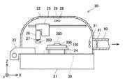
他の実施例に係る部品実装ライン1は、図5に示すように、送気ファン61を備えていてもよい。送気ファン61は、ダクト60の内部に配置されている。送気ファン61は、ダクト60の内部を流れる空気を部品実装装置20側からリフロー装置40側へ送る。送気ファン61の風量は、部品実装装置20のハウジング22の内部が正圧に維持されるように調節されている。 The component mounting line 1 according to another embodiment may include an
リフロー装置40でははんだ300をリフローするので、その温度が部品実装装置20の温度より高くなることが考えられる。そのため、リフロー装置40側から部品実装装置20側へ高温の空気が逆流する可能性がある。そこで、ダクト60の内部に送気ファン61を配置することによって、部品実装装置20側からリフロー装置40側へ空気を流し、空気が逆流しないようにしている。これによって、高温の空気を部品実装装置20からリフロー装置40へ確実に送ることができる。 Since the
また、上記の実施例では、部品実装装置20によって基板100の上にはんだ300を介して電子部品200が実装された後に、その基板100がリフロー装置40に送られ、リフロー装置40によってはんだ300がリフローされるとともに、部品実装装置20とリフロー装置40がダクト60によって接続されており、その部品実装装置20のハウジング22の内部の空気がリフロー装置40のハウジング42の内部に送られる構成であった。すなわち、リフロー装置40に送られる基板100と空気が、同じ部品実装装置20に由来する構成であった。しかしながら、この構成に限定されるものではない。他の実施例では、リフロー装置40に送られる基板100と空気が、異なる部品実装装置に由来する構成であってもよい。例えば、部品実装装置20によって基板100の上にはんだ300を介して電子部品200が実装された後に、その基板100がリフロー装置40に送られると共に、他の部品実装装置のハウジングの内部の空気がリフロー装置40のハウジング42の内部に送られてもよい。あるいは、他の部品実装装置によって基板100の上にはんだ300を介して電子部品200が実装された後に、その基板100がリフロー装置40に送られると共に、部品実装装置20のハウジング22の内部の空気がリフロー装置40のハウジング42の内部に送られてもよい。このような構成によっても、部品実装装置で生じる熱を有効に利用することができる。また、吸気ファン28(圧力装置の一例)を省略してもよい。 Further, in the above-described embodiment, after the
以上、本発明の具体例を詳細に説明したが、これらは例示に過ぎず、特許請求の範囲を限定するものではない。特許請求の範囲に記載の技術には、以上に例示した具体例を様々に変形、変更したものが含まれる。本明細書または図面に説明した技術要素は、単独であるいは各種の組合せによって技術的有用性を発揮するものであり、出願時請求項記載の組合せに限定されるものではない。また、本明細書または図面に例示した技術は複数目的を同時に達成し得るものであり、そのうちの一つの目的を達成すること自体で技術的有用性を持つものである。 Specific examples of the present invention have been described above in detail, but these are merely examples and do not limit the scope of the claims. The technology described in the claims includes various modifications and changes of the specific examples illustrated above. The technical elements described in the present specification or the drawings exert technical utility alone or in various combinations, and are not limited to the combinations described in the claims at the time of filing. In addition, the technique illustrated in the present specification or the drawings can simultaneously achieve a plurality of objects, and achieving the one object among them has technical utility.
1 :部品実装ライン
20 :部品実装装置
21 :ベース
22 :ハウジング
23 :フィーダー
24 :コンベア
25 :XYロボット
26 :ヘッド
27 :ノズル
28 :吸気ファン
29 :フィルタ
31 :排気ファン
39 :出入口
40 :リフロー装置
41 :コンベア
42 :ハウジング
43 :仕切壁
60 :ダクト
61 :送気ファン
90 :印刷装置
100 :基板
200 :電子部品
300 :はんだ
401 :予熱ゾーン
402 :加熱ゾーン
403 :冷却ゾーン
411 :予熱ヒーター
412 :予熱ファン
421 :加熱ヒーター
422 :加熱ファン
424 :出口
426 :入口
431 :冷却器
432 :冷却ファン1: Component mounting line 20: Component mounting device 21: Base 22: Housing 23: Feeder 24: Conveyor 25: XY robot 26: Head 27: Nozzle 28: Intake fan 29: Filter 31: Exhaust fan 39: Inlet / outlet 40: Reflow device 41: conveyor 42: housing 43: partition wall 60: duct 61: air supply fan 90: printing device 100: substrate 200: electronic component 300: solder 401: preheating zone 402: heating zone 403: cooling zone 411: preheating heater 412: Preheating fan 421: Heating heater 422: Heating fan 424: Outlet 426: Inlet 431: Cooler 432: Cooling fan
Claims (5)
Translated fromJapanese基板の上に電子部品が実装された後に、基板と電子部品の間に介在しているはんだを第2ハウジングの内部においてリフローするリフロー装置と、
前記部品実装装置と前記リフロー装置に接続されており、前記部品実装装置の前記第1ハウジングの内部の空気を前記リフロー装置の前記第2ハウジングの内部に送るダクトと、を備えている部品実装ライン。A component mounting apparatus for mounting an electronic component on a substrate via solder inside the first housing;
A reflow device that reflows the solder, which is interposed between the board and the electronic component, inside the second housing after the electronic component is mounted on the board;
A component mounting line that is connected to the component mounting apparatus and the reflow apparatus, and includes a duct that sends air inside the first housing of the component mounting apparatus to the inside of the second housing of the reflow apparatus. .
前記ダクトが、前記リフロー装置の前記第2ハウジングの前記出口よりも前記入口に近い位置に接続されている、請求項1から4のいずれか一項に記載の部品実装ライン。The second housing of the reflow device is provided with an inlet for loading a substrate on which electronic components are mounted and an outlet for unloading a substrate on which solder has been reflowed.
The component mounting line according to any one of claims 1 to 4, wherein the duct is connected to a position closer to the inlet than the outlet of the second housing of the reflow device.
Priority Applications (1)
| Application Number | Priority Date | Filing Date | Title |
|---|---|---|---|
| JP2016202405AJP6687495B2 (en) | 2016-10-14 | 2016-10-14 | Component mounting line |
Applications Claiming Priority (1)
| Application Number | Priority Date | Filing Date | Title |
|---|---|---|---|
| JP2016202405AJP6687495B2 (en) | 2016-10-14 | 2016-10-14 | Component mounting line |
Publications (2)
| Publication Number | Publication Date |
|---|---|
| JP2018064052A JP2018064052A (en) | 2018-04-19 |
| JP6687495B2true JP6687495B2 (en) | 2020-04-22 |
Family
ID=61966857
Family Applications (1)
| Application Number | Title | Priority Date | Filing Date |
|---|---|---|---|
| JP2016202405AActiveJP6687495B2 (en) | 2016-10-14 | 2016-10-14 | Component mounting line |
Country Status (1)
| Country | Link |
|---|---|
| JP (1) | JP6687495B2 (en) |
Families Citing this family (1)
| Publication number | Priority date | Publication date | Assignee | Title |
|---|---|---|---|---|
| DE112022007717T5 (en)* | 2022-08-30 | 2025-06-18 | Fuji Corporation | PCB processing machine |
Family Cites Families (5)
| Publication number | Priority date | Publication date | Assignee | Title |
|---|---|---|---|---|
| US6354481B1 (en)* | 1999-02-18 | 2002-03-12 | Speedline Technologies, Inc. | Compact reflow and cleaning apparatus |
| JP4211564B2 (en)* | 2003-10-16 | 2009-01-21 | パナソニック株式会社 | Substrate transport tray, substrate transport device, and electronic component mounting device |
| JP4291393B2 (en)* | 2008-02-25 | 2009-07-08 | パナソニック株式会社 | Electronic component mounting equipment |
| JP2012064907A (en)* | 2010-09-20 | 2012-03-29 | Toyota Motor Corp | Mounting machine with neutralizing function and neutralization method |
| KR20160064905A (en)* | 2014-11-28 | 2016-06-08 | 한화테크윈 주식회사 | System and method for mounting electric element |
- 2016
- 2016-10-14JPJP2016202405Apatent/JP6687495B2/enactiveActive
Also Published As
| Publication number | Publication date |
|---|---|
| JP2018064052A (en) | 2018-04-19 |
Similar Documents
| Publication | Publication Date | Title |
|---|---|---|
| EP2585245B1 (en) | Compression box for reflow oven heating and related method | |
| JP5801047B2 (en) | Reflow soldering apparatus and method | |
| JP2008124112A (en) | Reflow soldering method and apparatus | |
| JP2011171714A5 (en) | ||
| JP6687495B2 (en) | Component mounting line | |
| JP5264079B2 (en) | Heating device | |
| JP7445180B2 (en) | soldering equipment | |
| JPH10284832A (en) | Reflow soldering device | |
| JP3083035B2 (en) | Soldering equipment | |
| JP7587958B2 (en) | Transport heating device | |
| KR20160111498A (en) | Forced convection pre-heater for wave solder machine and related method | |
| JP6194807B2 (en) | Hume recovery device | |
| JP3597878B2 (en) | Atmosphere furnace exhaust gas suction device | |
| JP3404768B2 (en) | Reflow equipment | |
| JP2018162932A (en) | Reflow device | |
| JP4092258B2 (en) | Reflow furnace and temperature control method for reflow furnace | |
| JP2004195476A (en) | Cooling device for soldering, and reflow device | |
| JP2008221329A (en) | Heating apparatus | |
| JP3582989B2 (en) | Reflow soldering equipment | |
| JP5849163B1 (en) | Bonding apparatus and bonding method | |
| JP4017388B2 (en) | Reflow soldering equipment | |
| WO2019058546A1 (en) | Work device | |
| JP3245187U (en) | Reflow furnace | |
| JPH11298135A (en) | Heating furnace for soldering | |
| JPH04269895A (en) | Reflow solder method for printed board |
Legal Events
| Date | Code | Title | Description |
|---|---|---|---|
| A621 | Written request for application examination | Free format text:JAPANESE INTERMEDIATE CODE: A621 Effective date:20190808 | |
| TRDD | Decision of grant or rejection written | ||
| A01 | Written decision to grant a patent or to grant a registration (utility model) | Free format text:JAPANESE INTERMEDIATE CODE: A01 Effective date:20200317 | |
| A977 | Report on retrieval | Free format text:JAPANESE INTERMEDIATE CODE: A971007 Effective date:20200318 | |
| A61 | First payment of annual fees (during grant procedure) | Free format text:JAPANESE INTERMEDIATE CODE: A61 Effective date:20200402 | |
| R150 | Certificate of patent or registration of utility model | Ref document number:6687495 Country of ref document:JP Free format text:JAPANESE INTERMEDIATE CODE: R150 | |
| R250 | Receipt of annual fees | Free format text:JAPANESE INTERMEDIATE CODE: R250 | |
| R250 | Receipt of annual fees | Free format text:JAPANESE INTERMEDIATE CODE: R250 | |
| R250 | Receipt of annual fees | Free format text:JAPANESE INTERMEDIATE CODE: R250 |