JP6686156B2 - Methods of manufacturing medical devices and stent delivery systems - Google Patents
Methods of manufacturing medical devices and stent delivery systemsDownload PDFInfo
- Publication number
- JP6686156B2 JP6686156B2JP2018544201AJP2018544201AJP6686156B2JP 6686156 B2JP6686156 B2JP 6686156B2JP 2018544201 AJP2018544201 AJP 2018544201AJP 2018544201 AJP2018544201 AJP 2018544201AJP 6686156 B2JP6686156 B2JP 6686156B2
- Authority
- JP
- Japan
- Prior art keywords
- stent
- distal
- medical device
- region
- shaft
- Prior art date
- Legal status (The legal status is an assumption and is not a legal conclusion. Google has not performed a legal analysis and makes no representation as to the accuracy of the status listed.)
- Active
Links
Images


Classifications
- A—HUMAN NECESSITIES
- A61—MEDICAL OR VETERINARY SCIENCE; HYGIENE
- A61F—FILTERS IMPLANTABLE INTO BLOOD VESSELS; PROSTHESES; DEVICES PROVIDING PATENCY TO, OR PREVENTING COLLAPSING OF, TUBULAR STRUCTURES OF THE BODY, e.g. STENTS; ORTHOPAEDIC, NURSING OR CONTRACEPTIVE DEVICES; FOMENTATION; TREATMENT OR PROTECTION OF EYES OR EARS; BANDAGES, DRESSINGS OR ABSORBENT PADS; FIRST-AID KITS
- A61F2/00—Filters implantable into blood vessels; Prostheses, i.e. artificial substitutes or replacements for parts of the body; Appliances for connecting them with the body; Devices providing patency to, or preventing collapsing of, tubular structures of the body, e.g. stents
- A61F2/95—Instruments specially adapted for placement or removal of stents or stent-grafts
- A61F2/962—Instruments specially adapted for placement or removal of stents or stent-grafts having an outer sleeve
- A61F2/966—Instruments specially adapted for placement or removal of stents or stent-grafts having an outer sleeve with relative longitudinal movement between outer sleeve and prosthesis, e.g. using a push rod
- A—HUMAN NECESSITIES
- A61—MEDICAL OR VETERINARY SCIENCE; HYGIENE
- A61F—FILTERS IMPLANTABLE INTO BLOOD VESSELS; PROSTHESES; DEVICES PROVIDING PATENCY TO, OR PREVENTING COLLAPSING OF, TUBULAR STRUCTURES OF THE BODY, e.g. STENTS; ORTHOPAEDIC, NURSING OR CONTRACEPTIVE DEVICES; FOMENTATION; TREATMENT OR PROTECTION OF EYES OR EARS; BANDAGES, DRESSINGS OR ABSORBENT PADS; FIRST-AID KITS
- A61F2/00—Filters implantable into blood vessels; Prostheses, i.e. artificial substitutes or replacements for parts of the body; Appliances for connecting them with the body; Devices providing patency to, or preventing collapsing of, tubular structures of the body, e.g. stents
- A61F2/82—Devices providing patency to, or preventing collapsing of, tubular structures of the body, e.g. stents
- A61F2/86—Stents in a form characterised by the wire-like elements; Stents in the form characterised by a net-like or mesh-like structure
- A61F2/90—Stents in a form characterised by the wire-like elements; Stents in the form characterised by a net-like or mesh-like structure characterised by a net-like or mesh-like structure
- A—HUMAN NECESSITIES
- A61—MEDICAL OR VETERINARY SCIENCE; HYGIENE
- A61F—FILTERS IMPLANTABLE INTO BLOOD VESSELS; PROSTHESES; DEVICES PROVIDING PATENCY TO, OR PREVENTING COLLAPSING OF, TUBULAR STRUCTURES OF THE BODY, e.g. STENTS; ORTHOPAEDIC, NURSING OR CONTRACEPTIVE DEVICES; FOMENTATION; TREATMENT OR PROTECTION OF EYES OR EARS; BANDAGES, DRESSINGS OR ABSORBENT PADS; FIRST-AID KITS
- A61F2/00—Filters implantable into blood vessels; Prostheses, i.e. artificial substitutes or replacements for parts of the body; Appliances for connecting them with the body; Devices providing patency to, or preventing collapsing of, tubular structures of the body, e.g. stents
- A61F2/95—Instruments specially adapted for placement or removal of stents or stent-grafts
- A61F2/962—Instruments specially adapted for placement or removal of stents or stent-grafts having an outer sleeve
- A—HUMAN NECESSITIES
- A61—MEDICAL OR VETERINARY SCIENCE; HYGIENE
- A61M—DEVICES FOR INTRODUCING MEDIA INTO, OR ONTO, THE BODY; DEVICES FOR TRANSDUCING BODY MEDIA OR FOR TAKING MEDIA FROM THE BODY; DEVICES FOR PRODUCING OR ENDING SLEEP OR STUPOR
- A61M25/00—Catheters; Hollow probes
- A61M25/0009—Making of catheters or other medical or surgical tubes
- A—HUMAN NECESSITIES
- A61—MEDICAL OR VETERINARY SCIENCE; HYGIENE
- A61M—DEVICES FOR INTRODUCING MEDIA INTO, OR ONTO, THE BODY; DEVICES FOR TRANSDUCING BODY MEDIA OR FOR TAKING MEDIA FROM THE BODY; DEVICES FOR PRODUCING OR ENDING SLEEP OR STUPOR
- A61M25/00—Catheters; Hollow probes
- A61M25/0043—Catheters; Hollow probes characterised by structural features
- A61M25/005—Catheters; Hollow probes characterised by structural features with embedded materials for reinforcement, e.g. wires, coils, braids
- A61M25/0052—Localized reinforcement, e.g. where only a specific part of the catheter is reinforced, for rapid exchange guidewire port
- A—HUMAN NECESSITIES
- A61—MEDICAL OR VETERINARY SCIENCE; HYGIENE
- A61M—DEVICES FOR INTRODUCING MEDIA INTO, OR ONTO, THE BODY; DEVICES FOR TRANSDUCING BODY MEDIA OR FOR TAKING MEDIA FROM THE BODY; DEVICES FOR PRODUCING OR ENDING SLEEP OR STUPOR
- A61M25/00—Catheters; Hollow probes
- A61M25/01—Introducing, guiding, advancing, emplacing or holding catheters
- A61M25/0105—Steering means as part of the catheter or advancing means; Markers for positioning
- A61M25/0108—Steering means as part of the catheter or advancing means; Markers for positioning using radio-opaque or ultrasound markers
- A—HUMAN NECESSITIES
- A61—MEDICAL OR VETERINARY SCIENCE; HYGIENE
- A61M—DEVICES FOR INTRODUCING MEDIA INTO, OR ONTO, THE BODY; DEVICES FOR TRANSDUCING BODY MEDIA OR FOR TAKING MEDIA FROM THE BODY; DEVICES FOR PRODUCING OR ENDING SLEEP OR STUPOR
- A61M25/00—Catheters; Hollow probes
- A61M25/01—Introducing, guiding, advancing, emplacing or holding catheters
- A61M25/0105—Steering means as part of the catheter or advancing means; Markers for positioning
- A61M25/0133—Tip steering devices
- A61M25/0152—Tip steering devices with pre-shaped mechanisms, e.g. pre-shaped stylets or pre-shaped outer tubes
- A—HUMAN NECESSITIES
- A61—MEDICAL OR VETERINARY SCIENCE; HYGIENE
- A61F—FILTERS IMPLANTABLE INTO BLOOD VESSELS; PROSTHESES; DEVICES PROVIDING PATENCY TO, OR PREVENTING COLLAPSING OF, TUBULAR STRUCTURES OF THE BODY, e.g. STENTS; ORTHOPAEDIC, NURSING OR CONTRACEPTIVE DEVICES; FOMENTATION; TREATMENT OR PROTECTION OF EYES OR EARS; BANDAGES, DRESSINGS OR ABSORBENT PADS; FIRST-AID KITS
- A61F2/00—Filters implantable into blood vessels; Prostheses, i.e. artificial substitutes or replacements for parts of the body; Appliances for connecting them with the body; Devices providing patency to, or preventing collapsing of, tubular structures of the body, e.g. stents
- A61F2/95—Instruments specially adapted for placement or removal of stents or stent-grafts
- A61F2/9522—Means for mounting a stent or stent-graft onto or into a placement instrument
- A—HUMAN NECESSITIES
- A61—MEDICAL OR VETERINARY SCIENCE; HYGIENE
- A61F—FILTERS IMPLANTABLE INTO BLOOD VESSELS; PROSTHESES; DEVICES PROVIDING PATENCY TO, OR PREVENTING COLLAPSING OF, TUBULAR STRUCTURES OF THE BODY, e.g. STENTS; ORTHOPAEDIC, NURSING OR CONTRACEPTIVE DEVICES; FOMENTATION; TREATMENT OR PROTECTION OF EYES OR EARS; BANDAGES, DRESSINGS OR ABSORBENT PADS; FIRST-AID KITS
- A61F2240/00—Manufacturing or designing of prostheses classified in groups A61F2/00 - A61F2/26 or A61F2/82 or A61F9/00 or A61F11/00 or subgroups thereof
- A61F2240/001—Designing or manufacturing processes
- A—HUMAN NECESSITIES
- A61—MEDICAL OR VETERINARY SCIENCE; HYGIENE
- A61F—FILTERS IMPLANTABLE INTO BLOOD VESSELS; PROSTHESES; DEVICES PROVIDING PATENCY TO, OR PREVENTING COLLAPSING OF, TUBULAR STRUCTURES OF THE BODY, e.g. STENTS; ORTHOPAEDIC, NURSING OR CONTRACEPTIVE DEVICES; FOMENTATION; TREATMENT OR PROTECTION OF EYES OR EARS; BANDAGES, DRESSINGS OR ABSORBENT PADS; FIRST-AID KITS
- A61F2250/00—Special features of prostheses classified in groups A61F2/00 - A61F2/26 or A61F2/82 or A61F9/00 or A61F11/00 or subgroups thereof
- A61F2250/0014—Special features of prostheses classified in groups A61F2/00 - A61F2/26 or A61F2/82 or A61F9/00 or A61F11/00 or subgroups thereof having different values of a given property or geometrical feature, e.g. mechanical property or material property, at different locations within the same prosthesis
- A61F2250/0039—Special features of prostheses classified in groups A61F2/00 - A61F2/26 or A61F2/82 or A61F9/00 or A61F11/00 or subgroups thereof having different values of a given property or geometrical feature, e.g. mechanical property or material property, at different locations within the same prosthesis differing in diameter
- A—HUMAN NECESSITIES
- A61—MEDICAL OR VETERINARY SCIENCE; HYGIENE
- A61F—FILTERS IMPLANTABLE INTO BLOOD VESSELS; PROSTHESES; DEVICES PROVIDING PATENCY TO, OR PREVENTING COLLAPSING OF, TUBULAR STRUCTURES OF THE BODY, e.g. STENTS; ORTHOPAEDIC, NURSING OR CONTRACEPTIVE DEVICES; FOMENTATION; TREATMENT OR PROTECTION OF EYES OR EARS; BANDAGES, DRESSINGS OR ABSORBENT PADS; FIRST-AID KITS
- A61F2250/00—Special features of prostheses classified in groups A61F2/00 - A61F2/26 or A61F2/82 or A61F9/00 or A61F11/00 or subgroups thereof
- A61F2250/0058—Additional features; Implant or prostheses properties not otherwise provided for
- A61F2250/0096—Markers and sensors for detecting a position or changes of a position of an implant, e.g. RF sensors, ultrasound markers
- A61F2250/0098—Markers and sensors for detecting a position or changes of a position of an implant, e.g. RF sensors, ultrasound markers radio-opaque, e.g. radio-opaque markers
- A—HUMAN NECESSITIES
- A61—MEDICAL OR VETERINARY SCIENCE; HYGIENE
- A61M—DEVICES FOR INTRODUCING MEDIA INTO, OR ONTO, THE BODY; DEVICES FOR TRANSDUCING BODY MEDIA OR FOR TAKING MEDIA FROM THE BODY; DEVICES FOR PRODUCING OR ENDING SLEEP OR STUPOR
- A61M25/00—Catheters; Hollow probes
- A61M25/0021—Catheters; Hollow probes characterised by the form of the tubing
- A61M25/0023—Catheters; Hollow probes characterised by the form of the tubing by the form of the lumen, e.g. cross-section, variable diameter
- A61M2025/0024—Expandable catheters or sheaths
- A—HUMAN NECESSITIES
- A61—MEDICAL OR VETERINARY SCIENCE; HYGIENE
- A61M—DEVICES FOR INTRODUCING MEDIA INTO, OR ONTO, THE BODY; DEVICES FOR TRANSDUCING BODY MEDIA OR FOR TAKING MEDIA FROM THE BODY; DEVICES FOR PRODUCING OR ENDING SLEEP OR STUPOR
- A61M25/00—Catheters; Hollow probes
- A61M25/0021—Catheters; Hollow probes characterised by the form of the tubing
- A61M25/0023—Catheters; Hollow probes characterised by the form of the tubing by the form of the lumen, e.g. cross-section, variable diameter
- A61M25/0026—Multi-lumen catheters with stationary elements
- A61M2025/0039—Multi-lumen catheters with stationary elements characterized by lumina being arranged coaxially
- A—HUMAN NECESSITIES
- A61—MEDICAL OR VETERINARY SCIENCE; HYGIENE
- A61M—DEVICES FOR INTRODUCING MEDIA INTO, OR ONTO, THE BODY; DEVICES FOR TRANSDUCING BODY MEDIA OR FOR TAKING MEDIA FROM THE BODY; DEVICES FOR PRODUCING OR ENDING SLEEP OR STUPOR
- A61M25/00—Catheters; Hollow probes
- A61M25/01—Introducing, guiding, advancing, emplacing or holding catheters
- A61M2025/0175—Introducing, guiding, advancing, emplacing or holding catheters having telescopic features, interengaging nestable members movable in relations to one another
Landscapes
- Health & Medical Sciences (AREA)
- Engineering & Computer Science (AREA)
- Biomedical Technology (AREA)
- Life Sciences & Earth Sciences (AREA)
- Animal Behavior & Ethology (AREA)
- Veterinary Medicine (AREA)
- Public Health (AREA)
- Heart & Thoracic Surgery (AREA)
- General Health & Medical Sciences (AREA)
- Transplantation (AREA)
- Vascular Medicine (AREA)
- Oral & Maxillofacial Surgery (AREA)
- Cardiology (AREA)
- Biophysics (AREA)
- Pulmonology (AREA)
- Anesthesiology (AREA)
- Hematology (AREA)
- Prostheses (AREA)
- Materials For Medical Uses (AREA)
- Media Introduction/Drainage Providing Device (AREA)
Description
Translated fromJapanese本開示は、医療用デバイス、及び医療用デバイスを製造する方法に関する。より詳細には、本開示は縮小された外形を有するステント送達システムに関する。 The present disclosure relates to medical devices and methods of making medical devices. More particularly, the present disclosure relates to stent delivery systems having a reduced profile.
多種多様の体内医療用デバイスが、医療用に、例えば血管内に用いるために、開発されてきた。これらのデバイスのうちの一部にはガイドワイヤ、カテーテルなどが挙げられる。これらのデバイスは様々な異なる製造方法のうちのいずれか1つによって製造され、かつ様々な方法のうちのいずれか1つに従って使用されうる。 A wide variety of intracorporeal medical devices have been developed for medical use, eg, intravascular applications. Some of these devices include guidewires, catheters and the like. These devices may be manufactured by, and used in accordance with, any one of a variety of different manufacturing methods.
既知の医療用デバイス及び方法の中では、各々がある一定の長所及び短所を有する。代替の医療用デバイス、並びに医療用デバイスを製造及び使用するための代替方法を提供することが現在も必要とされている。 Among the known medical devices and methods, each has certain advantages and disadvantages. There is still a need to provide alternative medical devices and alternative methods for making and using medical devices.
本開示は、医療用デバイスのための設計、材料、製造方法、及び用途の代替案を提供する。例示的な医療用デバイスが開示される。医療用デバイスは、
ステント受け領域を有している内側シャフトと、
内側シャフトの周りに配置されたバンパーシャフトと、
内側シャフトの周りに摺動可能に配置された留置シースであって、留置シースは本体領域及び先端側ステントカバー領域を有しており、先端側ステントカバー領域は本体領域の外径よりも小さい外径を有している、留置シースと、
を含んでなる。The present disclosure provides alternative designs, materials, manufacturing methods, and applications for medical devices. An exemplary medical device is disclosed. Medical device
An inner shaft having a stent receiving area,
With a bumper shaft arranged around the inner shaft,
An indwelling sheath slidably disposed around an inner shaft, the indwelling sheath having a body region and a distal stent cover region, the distal stent cover region having an outer diameter smaller than an outer diameter of the body region. An indwelling sheath having a diameter,
Comprises.
上記の実施形態のうちいずれかの別例として又は追加として、ステント受け領域に沿って配置されたステントをさらに含んでなる。
上記の実施形態のうちいずれかの別例として又は追加として、バンパーシャフトは、本体区間と、本体区間の外径よりも小さい外径を備えた先端側区間とを有する。Alternatively or in addition to any of the above embodiments, it further comprises a stent disposed along the stent receiving area.
Alternatively or in addition to any of the above embodiments, the bumper shaft has a body section and a distal section having an outer diameter smaller than the outer diameter of the body section.
上記の実施形態のうちいずれかの別例として又は追加として、第1移行部が留置シースの本体領域と先端側ステントカバー領域との間に配置され、第2移行部がバンパーシャフトの本体区間と先端側区間との間に配置され、ステント長を有しているステントが内側部材に沿って配置され、第1移行部及び第2移行部は、留置シースがステントを覆って先端側に伸長しているときに距離をおいて離隔されている。 Alternatively or in addition to any of the above embodiments, the first transition is disposed between the body region of the indwelling sheath and the distal stent cover region and the second transition is the body section of the bumper shaft. A stent having a stent length, which is arranged between the distal section and the stent, is arranged along the inner member, and the first transition section and the second transition section are arranged such that the indwelling sheath extends distally over the stent. Are separated by a distance.
上記の実施形態のうちいずれかの別例として又は追加として、距離は少なくともステント長と同じ長さである。
上記の実施形態のうちいずれかの別例として又は追加として、距離は少なくともステント長の1.25倍である。Alternatively or in addition to any of the above embodiments, the distance is at least as long as the stent length.
Alternatively or in addition to any of the above embodiments, the distance is at least 1.25 times the stent length.
上記の実施形態のうちいずれかの別例として又は追加として、距離は少なくともステント長の1.5倍である。
上記の実施形態のうちいずれかの別例として又は追加として、バンパーシャフトに隣接して位置付けられたバンパーをさらに含んでなり、バンパーはバンパーシャフトの外径よりも大きい外径を有している。Alternatively or in addition to any of the above embodiments, the distance is at least 1.5 times the stent length.
Alternatively or in addition to any of the above embodiments, the method further comprises a bumper positioned adjacent to the bumper shaft, the bumper having an outer diameter greater than the outer diameter of the bumper shaft.
上記の実施形態のうちいずれかの別例として又は追加として、先端側ステントカバー領域は、患者の膝と足関節との間の距離を渡すのに適した長さを有する。
上記の実施形態のうちいずれかの別例として又は追加として、留置シースの少なくとも一部分に沿って配置された外側シャフトをさらに含んでなる。Alternatively or in addition to any of the above embodiments, the distal stent cover region has a length suitable for passing the distance between the patient's knee and ankle.
Alternatively or in addition to any of the above embodiments, it further comprises an outer shaft disposed along at least a portion of the deployment sheath.
上記の実施形態のうちいずれかの別例として又は追加として、階段式移行領域が留置シースの本体領域と留置シースの先端側ステントカバー領域との間に配置される。
上記の実施形態のうちいずれかの別例として又は追加として、傾斜式移行領域が留置シースの本体領域と留置シースの先端側ステントカバー領域との間に配置される。Alternatively or in addition to any of the above embodiments, a step transition region is disposed between the body region of the indwelling sheath and the distal stent cover region of the indwelling sheath.
Alternatively or in addition to any of the above embodiments, a tilted transition region is located between the body region of the indwelling sheath and the distal stent cover region of the indwelling sheath.
ステント送達システムを製造する方法が開示される。該方法は、
内側シャフトの周りにバンパーシャフトを配置するステップであって、内側シャフトはステント受け領域を有している、ステップと、
内側シャフトの周りに配置される留置シースを配置するステップであって、留置シースは、本体領域、先端側ステントカバー領域、及び本体領域と先端側ステントカバー領域との間の第1移行部を有し、先端側ステントカバー領域は本体領域の外径よりも小さい外径を有している、ステップと、
ステントをステント受け領域に沿って配置するステップであって、ステントはステント長を有している、ステップと、
バンパーシャフトは、本体部分、先端側部分、及び本体部分と先端側部分との間の第2移行部を有することと、
第1移行部は、少なくともステント長と同じ長さを有する距離だけ第2移行部から離隔されていることと、
を含んでなる。A method of manufacturing a stent delivery system is disclosed. The method is
Disposing a bumper shaft around the inner shaft, the inner shaft having a stent receiving area,
Deploying an indwelling sheath disposed about the inner shaft, the indwelling sheath having a body region, a distal stent cover region, and a first transition between the body region and the distal stent cover region. The distal stent cover region has an outer diameter smaller than the outer diameter of the main body region,
Disposing the stent along the stent receiving area, the stent having a stent length;
The bumper shaft has a body portion, a tip portion, and a second transition between the body portion and the tip portion;
The first transition is separated from the second transition by a distance having at least the same length as the stent length;
Comprises.
上記の実施形態のうちいずれかの別例として又は追加として、距離は少なくともステント長の1.25倍である。
上記の実施形態のうちいずれかの別例として又は追加として、距離は少なくともステント長の1.5倍である。Alternatively or in addition to any of the above embodiments, the distance is at least 1.25 times the stent length.
Alternatively or in addition to any of the above embodiments, the distance is at least 1.5 times the stent length.
医療用デバイスシステムが開示される。該医療用デバイスシステムは、
ステント受け領域を有している内側シャフトと、
ステント受け領域に沿って配置された自己拡張式ステントであって、ステント長を有しているステントと、
内側シャフトの周りに配置されたバンパーシャフトと、
内側シャフトの周りに摺動可能に配置された留置シースであって、留置シースは、本体領域、先端側ステントカバー領域、及び本体領域と先端側ステントカバー領域との間の第1移行部を有し、先端側ステントカバー領域は本体領域の外径よりも小さい外径を有している、留置シースと、
バンパーシャフトは、本体部分、先端側部分、及び本体部分と先端側部分との間の第2移行部を有することと、
第1移行部は、少なくともステント長と同じ長さを有する距離だけ第2移行部から離隔されていることと、
留置シースに連結されたハンドルと、
を含んでなる。A medical device system is disclosed. The medical device system comprises
An inner shaft having a stent receiving area,
A self-expanding stent disposed along a stent receiving area, the stent having a stent length,
With a bumper shaft arranged around the inner shaft,
An indwelling sheath slidably disposed about an inner shaft, the indwelling sheath having a body region, a distal stent cover region, and a first transition between the body region and the distal stent cover region. The distal side stent cover region has an outer diameter smaller than the outer diameter of the main body region, and an indwelling sheath,
The bumper shaft has a body portion, a tip portion, and a second transition between the body portion and the tip portion;
The first transition is separated from the second transition by a distance having at least the same length as the stent length;
A handle connected to the indwelling sheath,
Comprises.
上記の実施形態のうちいずれかの別例として又は追加として、距離は少なくともステント長の1.25倍である。
上記の実施形態のうちいずれかの別例として又は追加として、距離は少なくともステント長の1.5倍である。Alternatively or in addition to any of the above embodiments, the distance is at least 1.25 times the stent length.
Alternatively or in addition to any of the above embodiments, the distance is at least 1.5 times the stent length.
上記の実施形態のうちいずれかの別例として又は追加として、留置シースの少なくとも一部分に沿って配置された外側シャフトをさらに含んでなる。
上記の実施形態のうちいずれかの別例として又は追加として、第1移行部、第2移行部、又は両方が傾斜式移行部を備えている。Alternatively or in addition to any of the above embodiments, it further comprises an outer shaft disposed along at least a portion of the deployment sheath.
As an alternative or in addition to any of the above embodiments, the first transition, the second transition, or both include tilted transitions.
いくつかの実施形態についての上記概要は、本開示の各々の開示された実施形態又はあらゆる実装について説明するようには意図されていない。以降の図面及び詳細な説明は、これらの実施形態についてより詳細に例を示す。 The above summary of some embodiments is not intended to describe each disclosed embodiment or every implementation of the present disclosure. The figures and the detailed description that follow more particularly exemplify these embodiments.
本開示は、添付図面に関する以下の詳細な説明を考慮すればより完全に理解可能である。 The present disclosure may be more fully understood in view of the following detailed description of the accompanying drawings.
本開示には様々な改変形態及び代替形態が可能であるが、その具体像は図中に例として示されており、かつ詳細に説明されることになる。しかし当然のことながら、意図されるのは本発明を説明された特定の実施形態に限定することではない。それどころか、意図されているのは、本開示の趣旨及び範囲の内にある全ての改変形態、等価物、及び代替形態を対象とすることである。 While various modifications and alternatives are possible in this disclosure, specifics thereof have been shown by way of example in the drawings and will be described in detail. However, it should be understood that the intention is not to limit the invention to the particular embodiments described. On the contrary, the intention is to cover all modifications, equivalents, and alternatives falling within the spirit and scope of the disclosure.
以降の定義された用語については、特許請求の範囲又は本明細書中の他所において異なる定義が与えられないかぎり、これらの定義が適用されるものとする。
全ての数値は、本明細書中においては明示的に示されるか否かに関わらず用語「約」によって修飾されていると見なされる。用語「約」は一般に、当業者がその挙げられた値と等価である(例えば、同じ機能又は結果を有している)と考えるであろう数値の範囲を指す。多くの場合、用語「約」は最も近い有効数字に丸められる数を含みうる。For the following defined terms, these definitions shall be applied, unless a different definition is given in the claims or elsewhere in this specification.
All numerical values are considered herein to be modified by the term "about," whether or not explicitly indicated. The term “about” generally refers to a range of numbers that one of skill in the art would consider equivalent to the recited value (eg, having the same function or result). In many cases, the term "about" may include the number rounded to the nearest significant number.
端点による数値範囲の記述には、その範囲内の全ての数が含まれる(例えば、1〜5は、1、1.5、2、2.75、3、3.80、4、及び5を含んでいる)。
本明細書及び添付の特許請求の範囲において使用されるように、単数形「1つの(a)」、「1つの(an)」及び「その(the)」は、内容がそうでないことを明らかに示していないかぎり、複数の指示物を含む。本明細書及び添付の特許請求の範囲において使用されるように、用語「又は、若しくは(or)」は一般に、内容がそうでないことを明らかに示していないかぎり、「(〜及び…の)うち少なくともいずれか一方(and/or)」を含んでいる意味で使用される。The description of numerical ranges by endpoints includes all numbers within that range (eg, 1 to 5 are 1, 1.5, 2, 2.75, 3, 3.80, 4, and 5). Including).
As used in this specification and the appended claims, the singular forms "a", "an" and "the" are clear that the content is not. Includes multiple indicators unless otherwise indicated. As used in this specification and the appended claims, the term "or" or "or" generally refers to "of (to and ...) unless the content clearly dictates otherwise. The term "and / or" is used in the meaning.
留意されるのは、「実施形態」、「いくつかの実施形態」、「他の実施形態」などへの本明細書中における言及は、その記載された実施形態が1以上の特定の特徴、構造、及び特性のうち少なくともいずれかを備えうることを示している、ということである。しかしながら、そのような記述は必ずしも、全ての実施形態がその特定の特徴、構造、及び特性のうち少なくともいずれかを備えることを意味してはいない。加えて、特定の特徴、構造、及び特性のうち少なくともいずれかが1つの実施形態に関して記載される場合、当然ながらそのような特徴、構造、及び特性のうち少なくともいずれかは、そうでないことが明白に述べられないかぎり、明示的に記載されるか否かに関わらず他の実施形態に関して(connection whith)も使用可能である。 It should be noted that references herein to "embodiments", "some embodiments", "other embodiments", etc., refer to that described embodiment as to one or more particular features, It means that the structure and / or the property can be provided. However, such description does not necessarily mean that all the embodiments include the specific features, structures, and / or characteristics. In addition, where particular features, structures and / or characteristics are described in connection with one embodiment, it is, of course, obvious that such features, structures and / or characteristics are not. Unless stated otherwise, connection with other embodiments may be used, whether explicitly stated or not.
以下の詳細な説明は図面を参照して読まれるべきであり、図面において異なる図中の同様の要素には同じ番号が付けられている。図面(必ずしも一定の縮尺ではない)は例示の実施形態を示しており、本発明の範囲を限定するようには意図されていない。 The following detailed description should be read with reference to the drawings, in which like elements in different drawings are numbered the same. The drawings (not necessarily to scale) show exemplary embodiments and are not intended to limit the scope of the invention.
数多くの機械的特質が、ステント送達システム(例えば自己拡張式ステント送達システム)にとって重要となりうる。これらの特質のうちの一部としては、追従性(trackability)、押し込み性(pushability)、伝送に関する特質(ステント留置力)、デバイスの外形などが挙げられる。これらの特質のうちの1つにおける変化が1以上の他の特質に影響を与えうることは理解できる。例えば、ステント送達システムの外形を縮小することが望ましい場合がある。このことは、アクセス部位の大きさを最小限にすること、及び、小さな解剖学的構造上の脈管/標的部へのアクセスを可能にすること、のうち少なくともいずれか一方の助けになりうる。外形を縮小すると同時に、比較的深部の脈管部位にアクセスするために、押し込み性及び追従性のうち少なくともいずれか一方を所望のレベルに維持することが望ましい場合がある。本明細書中に開示されるのは、例えば外形、押し込み性、及び追従性を含む機械的特質の望ましいバランスを提供するように設計されたステント送達システムである。これにより、本明細書中に開示されたシステムが、ステントの送達及び留置のうち少なくともいずれか一方のために、例えば「膝より下方」又はそうでなければ膝と足関節との間の標的脈管などの比較的小さな解剖学的構造上の領域にアクセスすることを可能にすることができる。他の標的、例えば末梢血管、心臓血管、頚動脈、神経脈管、その他の脈管場所、又は他の体管腔なども企図される。 Numerous mechanical properties can be important for stent delivery systems (eg, self-expanding stent delivery systems). Some of these attributes include trackability, pushability, transmission characteristics (stent placement force), device profile, and the like. It is understood that changes in one of these characteristics can affect one or more other characteristics. For example, it may be desirable to reduce the profile of the stent delivery system. This may help minimize the size of the access site and / or allow access to small anatomical vessels / targets. . It may be desirable to maintain a desired level of pushability and / or compliance at a desired level in order to access a relatively deep vascular site while reducing the profile. Disclosed herein are stent delivery systems designed to provide the desired balance of mechanical properties including profile, pushability, and compliance. This allows the system disclosed herein to provide a target pulse for delivery and / or placement of a stent, eg, “below the knee” or otherwise between the knee and ankle. It may be possible to access a relatively small anatomical area such as a tube. Other targets are also contemplated, such as peripheral blood vessels, cardiovascular, carotid, neurovascular, other vascular locations, or other body lumens.
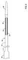
図1は、例示的なステント送達システム10を例証している。システム10は、長尺状シャフト12、及び該シャフト12に連結されたハンドル14を備えうる。一般に、システム10は患者の体管腔内の対象エリアへとステント、グラフト、体内プロテーゼなどを送達するために使用可能である。体管腔は、心臓の近くに(例えば心臓血管の内部若しくは近くに)、末梢血管内に、神経脈管内に、又は任意の他の適切な場所にある血管であってもよい。ステントの留置には、ステントの送達の間ステントを覆うか又はそうでなければカバーするように設計されている留置シース16の基端側への引き込みが含まれうる。留置シース16の引き込みには、ハンドル14に一般に配置される駆動部材18の駆動が含まれうる。図1に例証された実施例において、駆動部材18は、留置シース16の基端側への引き込みを遂行するために医師が回転させることが可能なサムホイールである。多数の他の駆動部材が企図される。加えて、シャフト12はさらに、先端側チップ26を終端とする内側シャフト又はライナー(例えば図3に例証されるような内側シャフト24)も備えうる。 FIG. 1 illustrates an exemplary
留置シース16は歯竿19に連結されてもよい。歯竿19は、駆動部材18の上にあるか又は同部材に隣接したギア/歯に係合するように設計された、突部又は歯(図示せず)を備えうる。プルハンドル20及びルアーフィッティング22も歯竿19の基端部に配置可能である。プルハンドル20は、留置シース16の迅速な又は進路通りの引き込みを可能にすることができる。ルアーフィッティング22は、システム10の様々な部品をフラッシュするために使用可能である。ルアーフィッティング22はさらに、ガイドワイヤアクセスポートとしての役割も果たすことができる。 The indwelling
ある場合には、システム10は外側シャフト28を備えうる。外側シャフト28は、留置シース16に沿った摩擦の低減により留置力を低減するのに役立つ場合がある。摩擦をさらに低減するために、シリコーン潤滑剤のような潤滑剤が、留置シース16、外側シャフト28、及びシステム10の他の部品の一部に沿って配置されてもよい。図2に示されるように、例示的なステント送達システム110(形態及び機能において本明細書中に開示された他のシステムに類似しうる)は、外側シャフト28を省略してもよいし、又はそうでなければ外側シャフト28を欠いている。例えば、システム10は「三軸の」システムである(例えば、内側シャフト24、留置シース16、及び外側シャフト28を備えており、さらにバンパーシャフト38も備えている)と考えられる一方、システム110は「二軸の」又は「共軸の」システムである(例えば、内側シャフト24及び留置シース16を備えており、さらにバンパーシャフト38も備えている)と考えられる。 In some cases, the
上記に示されるように、システム10及びシステム110のうち少なくともいずれか一方は縮小された外形を有することが望ましいかもしれない。ある場合には、留置シース16は本体領域30及び先端側ステントカバー領域32を備えうる。先端側ステントカバー領域32は、本体領域30と比較して縮小された外径を有しうる。例えば、本体領域30は、約4〜8フレンチ(1.333〜2.667mm;0.053〜0.105インチ)、又は約5〜6フレンチ(1.667〜2mm;0.066〜0.079インチ)、又は約5.5フレンチ(1.833mm;0.072インチ)の外径を有しうる。先端側ステントカバー領域32は、約4〜8フレンチ(1.333〜2.667mm;0.053〜0.105インチ)、又は約4〜6フレンチ(1.333〜2mm;0.053〜0.079インチ)、又は約5フレンチ(1.667;0.066インチ)の外径を有しうる。本体領域30は、約76.2〜177.8cm(約30〜70インチ)、又は約88.9〜139.7cm(約35〜55インチ)、又は約104.9cm(約41.3インチ)の長さを有しうる。先端側ステントカバー領域32は、約10〜30インチ(25.4〜76.2cm)若しくは約15〜20インチ(38.1〜50.8cm)ほど、又は約17.7インチ(45cm)の長さを有しうる。少なくとも一部の場合には、先端側ステントカバー領域32の長さは、膝と足関節との間の脈管の場所にアクセスするのに適切であるように、おおよそ患者の膝と足関節との間の距離であってもよい。寸法の範囲が本明細書中に提示されているが、他の寸法も企図される。 As indicated above, it may be desirable for
ある場合には、先端側ステントカバー領域32は、留置シース16の壁厚を縮小することにより形成可能である。そのような場合、留置シース16の内径はほぼ一定のままであってもよい。別例として、留置シース16の壁厚がほぼ一定のままであってもよい。そのような場合、本体領域30の内径は、先端側ステントカバー領域32の内径よりも大きくてよい。本体領域30及び先端側ステントカバー領域32のうち少なくともいずれか一方の壁厚及び内径が両方とも変化しうるその他の事例も企図される。 In some cases, the distal
システム10(及びシステム110のうち少なくともいずれか一方)は、図3に例証されるような内側部材24を備えうる。少なくともいくつかの実施形態では、内側部材24は管状構造であってもよく、よってルーメン(図示せず)を備えうる。ルーメンは、内側部材24の長さの少なくとも一部分に沿って伸びるガイドワイヤルーメンであってもよい。従って、システム10(及びシステム110のうち少なくともいずれか一方)は、脈管構造中の所望の標的場所へとガイドワイヤ上を前進させることができる。少なくともある場合には、内側シャフト24及び該シャフトを通って伸びるルーメンのうち少なくともいずれか一方は、適切なガイドワイヤを収容する大きさに作ることができる。例えば、内側シャフト24は、0.36mm(0.014インチ)のガイドワイヤ、0.46mm(0.018インチ)のガイドワイヤ、0.89mm(0.035インチ)のガイドワイヤ、又は他の適切なサイズのものを収容するのに適した内径を有しうる。そのため、内側シャフト24は、約0.25〜1.3mm(約0.010〜0.050インチ)、約0.30〜0.64mm(約0.012〜0.025インチ)、約0.51mm(約0.020インチ)、又は他の対応する大きさの内径を有しうる。加えて、又は代替実施形態では、ルーメンは、システム10(及びシステム110のうち少なくともいずれか一方)の一部分、構成部分、又は全てについてフラッシング、潅流、吸引などが行われるのを可能にする潅流/吸引ルーメンであってもよい。 System 10 (and / or system 110) may include an
内側シャフト24は、編組体、コイル、又は同種のもののような補強材(図示せず)を備えてもよい。ある場合には、補強材は内側シャフト24の全長に沿って伸びてもよい。他の場合には、補強材は内側シャフト24の1以上の離散した部分に沿って伸びてもよい。
内側部材24は、ステント(例えば、図4のステント36)をその周りに配置可能なステント受け領域34を備えうる。ステント受け領域34の長さ及び構成のうち少なくともいずれか一方は様々であってもよい。例えば、ステント受け領域34はステントがその上に配置されるのに十分な長さを有しうる。システム10(及びシステム110のうち少なくともいずれか一方)に利用されるステントの長さが長くなるにつれて、ステント受け領域34の長さも長くなることは理解されよう。
ステント受け領域34に沿って、又はそうでなければ該領域に隣接して配置されて、1以上の潅流ポート(図示せず)があってもよい。潅流ポートは、内側部材24のルーメンを通して流体を注入し、かつポートを通して流すことができるように、内側部材24の壁を通して伸びていてもよい。これはいくつかの理由で望ましいかもしれない。例えばポートは、医師が、該ポートを通して流体を潅流させることにより、ステント近くで捕捉される場合のある気泡を抜くことを可能にすることができる。加えて、ポートは、廃棄してよい流体を内側部材24に沿って吸引するために使用することができる。ポートはさらに、システム10(及びシステム110のうち少なくともいずれか一方)を販売用に準備する際に関わる場合のある滅菌及び/又はその他の準備処理のステップに役立つ場合がある。 There may be one or more perfusion ports (not shown) located along or otherwise adjacent to the
先端側チップ26は内側部材24の先端部に取り付けられてもよいし、他の方法で先端部に配置されてもよい。先端側チップ26は概して、システム10に概ね非外傷性の先端部を提供する丸みを帯びた形状又は平滑な形状を有しうる。先端側チップ26はさらに、該チップに形成された1以上の切り取り部(cutout)又は平ら部(flat)(図示せず)を備えてもよい。本開示においては、平ら部は、先端側チップ26の外側寸法又は外形が縮小される場である、先端側チップ26の切り取り部又は平らな部分であると理解できる。「平ら部」という名称は、これらの領域が、一般に丸みを帯びた外形を有しうる先端側チップ26の残りの部分と比較して、幾分「平らな」外観を有しうるという事実から来る。しかしながら平ら部の形状は、多数の形状が企図されるので平らである又は平面であることに限定されるようには意図されない。平ら部は、留置シース16が先端側チップ26と当接するか又は他の方法で接触するときに内側部材24と留置シース16との間に隙間又は空間が画成されるのを可能にすることができる。 The
図4は、システム10(及びシステム110のうち少なくともいずれか一方)の何らかのさらなる構造を備えた内側部材24を例証する。図4に示されるように、ステント36が内側部材24の周りに(例えば、内側部材24のステント受け領域34の周りに)配置されている。いくつかの実施形態では、ステント36は自己拡張式ステントである。従って、ステント36は外側に向かって拡張するように付勢されることができる。このため、ステント36は厳密な意味では内側部材24に「装荷され」ないかもしれず、むしろ内側部材24の周りに配置されているか又は同部材を取り囲んでいると考えることができる。ステント36はその後、留置シース16の内側に拘束されうる。しかしながら、代替実施形態では、ステント36は、圧接又は任意の他の適切な機械的把持機構によって、内側部材24に直接装荷されることもできる。 FIG. 4 illustrates
バンパーシャフト38も内側部材24の上に配置されうる。少なくともいくつかの実施形態では、バンパーシャフト38は、内側部材24の基端部に隣接する位置から内側部材24の先端部の基端側の位置へと延在することができる。バンパーシャフト38は、バンパーを備えること又はそうでなければバンパーとして機能することが可能であり、よって、ステント36の航行及び留置のうち少なくともいずれか一方の際の、ステント36の何らかの望ましからぬ基端側への移動を低減及び/又は防止することができる。バンパーシャフト38は、編組体、コイル、又は同種のもののような補強材(図示せず)を備えることができる。ある場合には、補強材はバンパーシャフト38の全長に沿って伸びてもよい。他の場合には、補強材はバンパーシャフト38の1以上の離散した部分に沿って伸びてもよい。 The
留置シース16と同じように、バンパーシャフト38は本体区間40および先端側区間42を備えうる。先端側区間42は、本体区間40の外径に対して縮小された外径を有しうる。第1移行部41が区間40/42の間に配置されてもよい。ある場合には、第1移行部41は、図4に示されるような傾斜式移行部又はテーパ状部の形態をとることができる。他の場合には、第1移行部41は、階段状の移行部(例えば、本体区間40から先端側区間42への90度の降段)であってもよい。その他の移行部も企図される。先端側区間42はバンパーシャフト38の壁厚を縮小することにより形成されうる。そのような場合、バンパーシャフト38の内径はほぼ一定のままであることができる。別例として、バンパーシャフト38の壁厚がほぼ一定のままであってもよい。そのような場合、本体区間40の内径は先端側区間42の内径よりも大きくてよい。 Like the indwelling
ある場合には、バンパーとして機能するバンパーシャフト38ではなく、別個のバンパー45が図5に示されるようにバンパーシャフト38及び内側部材24のうち少なくともいずれか一方に結合されてもよい。バンパー45は、例えばステント留置の際に、ステント36の基端側への移動を低減するのに役立つことができる。 In some cases, rather than
図6は、システム10(及びシステム110のうち少なくともいずれか一方)のさらなる構造を例証する。留置シース16は、内側部材24、バンパーシャフト38、及びステント36の上に配置されている。留置シース16は、留置シース16がステント36を覆って配置されるようになっている、例えば図6に示されるような第1の配置状態と、留置シース16がステント36の実質的に基端側の位置まで基端側に引き込まれている第2の配置状態との間で変化するように構成される。一般に、第1の配置状態は、体管腔内の適切な場所へのシステム10(及びシステム110のうち少なくともいずれか一方)の航行の際に利用可能であり、第2の配置状態はステント36を留置するために使用することができる。 FIG. 6 illustrates additional structure of system 10 (and / or system 110). Indwelling
少なくともいくつかの実施形態では、留置シース16は、部分30と部分32との間に第2移行領域43を備えうる。留置シース16はさらに、該シースに埋設又は他の方法で具備された補強部材44を備えうる。補強部材44は様々な異なる構成を有することができる。例えば、補強部材44は、編組体、コイル、メッシュ、これらの組み合わせなど、又は任意の他の適切な構成を備えることができる。いくつかの実施形態では、補強部材44は留置シース16の全長に沿って延在してもよい。他の実施形態では、補強部材44は、留置シース16の長さの1以上の部分に沿って延在してもよい。留置シース16はさらに、放射線不透性マーカー46を備えることができる。一般に、放射線不透性マーカー46は、留置シース16の先端部48に隣接して配置することができる。1以上のさらなる放射線不透性マーカー46が、留置シース16の他の部分又はシステム10(及びシステム110のうち少なくともいずれか一方)の他の部分に沿って配置されてもよい。マーカーバンド46は、留置シース16の先端部48が、システム10(及びシステム110のうち少なくともいずれか一方)の前進及びステント36の留置のうち少なくともいずれか一方の際に蛍光透視法で視覚化されるのを可能にすることができる。留置シース16はさらに、ポリテトラフルオロエチレン(PTFE)又は他の適切な材料を含む内部層又は内張りを備えることができる。 In at least some embodiments,
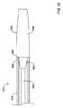
図7に示されるように、先端側ステントカバー領域32は第1の長さL1を有する。バンパーシャフト38の先端側区間42は第2の長さL2を有する。ステント36は第3の長さL3を有する。第2移行部43は第1移行部41から距離D1だけ離隔されている。距離D1は、ステントの長さL3以上であってもよい(例えば、留置シース16がステント36を覆って先端側へ伸長される場合)。これにより、第2移行部43が第1移行部41と接触する前に留置シース16を引き込んでステント36を留置させることが可能となる。換言すれば、ステント36を留置するために、留置シース16は、留置シース16の先端部がステント36の基端部より基端側に配置される位置まで基端側へと引き込まれることになる。先端側ステントカバー領域32はバンパーシャフト38の外径よりも小さい内径を有しうるので、留置シース16が基端側へ引き込まれることが可能な距離は距離D1によって制限されうる。よって、留置シース16を基端側へ引き込んでステント36を留置するためには、距離D1はステントの長さL3以上である。ある場合には、距離D1は、ステントの長さL3と少なくとも同じ、又はL3の約1〜5倍、又はL3の約1〜3倍、又はL3の約1〜2倍、又はL3の約1.25〜1.5倍の長さであってもよい。少なくともいくつかの場合には、距離D1は、約1〜30cm、又は約5〜20cm、又は約10〜15cm、又は約15cm程度であってもよい。 As shown in FIG. 7, the distal
図8は、ステント36を留置するために基端側へ引き込まれた留置シース16を例証している。例えば、留置シース16は、第1移行部41が第2移行部43に隣接して配置されている配置状態へと基端側に引き込まれることが可能である。こうなると、自己拡張式であるステント36は、例えば標的領域の内部で、拡張することができる。距離D1がステントの長さL3と等しいか又はほぼ等しい場合、第1移行部41及び第2移行部43は互いに接触しうることに留意すべきである。距離D1がステントの長さL3より大きい場合には、第1移行部41及び第2移行部43は軸方向に間隔を置いて離隔されうる。
FIG. 8 illustrates the
図9〜13はその他の企図される管状部材(例えば、留置シース16及びバンパーシャフト38のうち少なくともいずれか一方)を例証する。本開示に関しては、図9〜13は、留置シース16及びバンパーシャフト38のうち少なくともいずれか一方に利用可能な他の構成の例として理解することができる。例えば、図9は、第1の区間101、第2の区間102、及び区間101と102との間の階段移行部103を有している管状部材100を例証している。よって、管状部材は、階段移行部によって隔てられた2つの区間を一般に備えていることが企図される。図10は、第1の区間201、第2の区間202、及び第3の区間203を有している管状部材200を例証している。階段移行部204は区間201と202との間に配置可能である。階段移行部205は区間202と203との間に配置可能である。よって、管状部材は、階段式移行部によって隔てられた少なくとも3つの別個の区間を一般に備えていることが企図される。すなわち、管状部材は、各区間が少なくとも1つの階段式移行部によって隣接区間から識別可能であるような、多数の区間及び多数の階段式移行部が交互になっている構成を一般に備えていることが企図される。図11は、第1の区間301、第2の区間302、及び第3の区間303を有している管状部材300を例証している。傾斜式移行部304は区間301と302との間に配置可能である。傾斜式移行部305は区間302と303との間に配置可能である。よって、傾斜式移行部によって隔てられた3つの区間を一般に備えている管状部材が企図される。図12は、第1の区間401、第2の区間402、第3の区間403、及び第4の区間404を有している管状部材400を例証している。階段移行部405は区間401と402との間に配置可能である。階段移行部406は区間402と403との間に配置可能である。階段移行部407は区間403と404との間に配置可能である。よって、階段式移行部によって隔てられた4つの区間を一般に備えている管状部材が企図される。図13は、第1の区間501、第2の区間502、第3の区間503、及び第4の区間504を有している管状部材500を例証している。傾斜式移行部505は区間501と502との間に配置可能である。傾斜式移行部506は区間502と503との間に配置可能である。傾斜式移行部507は区間503と504との間に配置可能である。よって、傾斜式移行部によって隔てられた4つの区間を備えている管状部材が企図される。すなわち、管状部材は、各区間が少なくとも1つの傾斜式移行部によって隣接区間から識別可能であるような、多数の区間及び多数の傾斜式移行部が交互になっている構成を一般に備えていることが企図される。特に、他の管状部材であって、適切な数(例えば1、2、3、4個若しくはそれ以上)の移行部を備えていること、及び、階段式移行部、傾斜式移行部、若しくは両方を利用すること、のうち少なくともいずれかである管状部材が企図される。 9-13 illustrate other contemplated tubular members (eg, indwelling
図14〜17は、企図されたチップ構成のうちのいくつかを例証している。例えば、図14は、留置シース16の先端側ステントカバー領域32の内径ID以下である外径ODを有している先端側チップ26を備えたシステム10を例証する。図15は、形態及び機能において本明細書中に開示された他のシステムに類似しうるシステム610であって、内側部材624が先端側チップ626を備えているシステムを例証する。先端側チップ626は、基端側レッジ650、狭小領域652、及び先端側テーパ状領域654を有している。図16に示されるように、狭小領域652は留置シース616(例えば、留置シース616の先端側ステントカバー領域)の内側に嵌合するように設計可能であり、かつレッジ650は、留置シース616の先端部648に当接することができる。図17は、形態及び機能において本明細書中に開示された他のシステムに類似しうるシステム710であって、留置シース716及び内側シャフト724を備えているシステムを例証する。先端側チップ726は内側シャフト724に結合されることができる。先端側チップ726は、レッジ(例えば図15〜16に示されるようなレッジ650)ではなく滑らかに推移する直径を有することができる。加えて、留置シース716の先端部は、面取り又は他の方法で丸みを付けられたチップを有しうる。その他のチップの幾何学的形状及び外形も企図される。 14-17 illustrate some of the contemplated chip configurations. For example, FIG. 14 illustrates
本明細書中に開示されたシステムの様々な構成要素及び本明細書中に開示された様々な管状部材に使用することが可能な材料には、医療用デバイスに一般に関連するものが挙げられる。簡潔にするために、以降の論考はシステム10の留置シース16及びその他の構成要素について述べる。しかしながら、これは本明細書中に記載されるデバイス及び方法を限定するように意図されるものではない、というのも、その論考は本明細書中に開示された他の類似の管状部材及び管状部材又はデバイスの構成要素のうち少なくともいずれかに適用可能であるからである。 Materials that can be used for the various components of the systems disclosed herein and the various tubular members disclosed herein include those commonly associated with medical devices. For brevity, the discussion that follows describes indwelling
留置シース16及びシステム10のその他の構成要素のうち少なくともいずれかは、金属、金属合金、ポリマー(そのいくつかの例は以下に開示される)、金属‐ポリマー複合材料、セラミックス、これらの組み合わせなど、又はその他の適切な材料から作製することができる。適切なポリマーのいくつかの例には、ポリテトラフルオロエチレン(PTFE)、エチレンテトラフルオロエチレン(ETFE)、フッ素化エチレンプロピレン(FEP)、ポリオキシメチレン(POM、例えばデュポン(DuPont)から入手可能なDELRIN(登録商標))、ポリエーテルブロックエステル、ポリウレタン(例えば、ポリウレタン85A)、ポリプロピレン(PP)、ポリ塩化ビニル(PVC)、ポリエーテルエステル(例えば、DSMエンジニアリングプラスチックス(DSM Engineering Plastics)から入手可能なARNITEL(登録商標))、エーテル系若しくはエステル系共重合体(例えばブチレン/ポリ(アルキレンエーテル)フタラート、及びデュポンから入手可能なHYTREL(登録商標)のような他のポリエステルエラストマー、のうち少なくともいずれか)、ポリアミド(例えば、バイエル(Bayer)から入手可能なDURETHAN(登録商標)、エルフ・アトケム(Elf Atochem)から入手可能なCRISTAMID(商標)、VESTAMID(登録商標)など)、弾性ポリアミド、ブロックポリアミド/エーテル、ポリエーテルブロックアミド(PEBA、例えば商品名PEBAX(登録商標)として入手可能なもの)、エチレン酢酸ビニル共重合体(EVA)、シリコーン、ポリエチレン(PE)、Marlex(登録商標)高密度ポリエチレン、Marlex(登録商標)低密度ポリエチレン、直鎖状低密度ポリエチレン(例えばREXELL(商標))、ポリエステル、ポリブチレンテレフタラート(PBT)、ポリエチレンテレフタラート(PET)、ポリトリメチレンテレフタラート、ポリエチレンナフタラート(PEN)、ポリエーテルエーテルケトン(PEEK)、ポリイミド(PI)、ポリエーテルイミド(PEI)、ポリフェニレンスルフィド(PPS)、ポリフェニレンオキシド(PPO)、ポリパラフェニレンテレフタルアミド(例えばKEVLAR(登録商標))、ポリスルホン、ナイロン、ナイロン12(EMSアメリカン・グリロン(EMS American Grilon)から入手可能なGRILAMID(登録商標)など)、ペルフルオロ(プロピルビニルエーテル)(PFA)、エチレンビニルアルコール、ポリオレフィン、ポリスチレン、エポキシ、ポリ塩化ビニリデン(PVdC)、ポリ(スチレン‐b‐イソブチレン‐b‐スチレン)(例えば、SIBS及びSIBS50Aのうち少なくともいずれか)、ポリカーボネート、アイオノマー、生体適合性ポリマー、他の適切な材料、又はこれらの混合物、組み合わせ、共重合体、ポリマー/金属複合材料など、が挙げられる。いくつかの実施形態では、シースには液晶ポリマー(LCP)を混ぜ合わせることが可能である。例えば、該混合物は最大で約6パーセントのLCPを含有することが可能である。 Indwelling
適切な金属及び金属合金のいくつかの例としては、ステンレス鋼、例えば304V、304L及び316LVステンレス鋼など、軟鋼、ニッケル‐チタン合金、例えば線形弾性及び超弾性のうち少なくともいずれか一方のニチノール(登録商標)など、他のニッケル合金、例えばニッケル‐クロム‐モリブデン合金(例えば、UNS:N06625、例えばINCONEL(登録商標)625など、UNS:N06022、例えばHASTELLOY(登録商標)C‐22(商標)など、UNS:N10276、例えばHASTELLOY(登録商標)C276(商標)、その他のHASTELLOY(登録商標)合金など、及び同種のもの)、ニッケル銅合金(例えば、UNS:N04400、例えばMONEL(登録商標)400、NICKELVAC(商標)400、NICORROS(登録商標)400など、及び同種のもの)、ニッケル‐コバルト‐クロム‐モリブデン合金(例えば、UNS:R30035、例えばMP35‐N(商標)など)、ニッケル‐モリブデン合金(例えば、UNS:N10665、例えばHASTELLOY(登録商標)ALLOY B2(商標)など)、他のニッケル‐クロム合金、他のニッケル‐モリブデン合金、他のニッケル‐コバルト合金、他のニッケル鉄合金、他のニッケル銅合金、他のニッケル‐タングステン若しくはタングステン合金など、コバルト‐クロム合金、コバルト‐クロム‐モリブデン合金(例えば、UNS:R30003、例えばELGILOY(登録商標)、PHYNOX(登録商標)など、及び同種のもの)、白金強化型(platinum enriched)ステンレス鋼、チタン、これらの組み合わせ、並びに同種のもの、又は任意の他の適切な材料、が挙げられる。 Some examples of suitable metals and metal alloys include stainless steels such as 304V, 304L and 316LV stainless steels, mild steels, nickel-titanium alloys such as linear and / or superelastic nitinol. Other nickel alloys, such as nickel-chromium-molybdenum alloys (e.g. UNS: N06625, e.g. INCONEL (R) 625, UNS: N06022, e.g. HASTELLOY (R) C-22 (TM), etc., UNS: N10276, such as HASTELLOY® C276 ™, other HASTELLOY® alloys, and the like, and nickel copper alloys (eg, UNS: N04400, such as
少なくともいくつかの実施形態では、システム10の部分又は全部が、放射線不透性物質を添加されるか、同物質で作製されるか、又はそうでなければ同物質を含むことができる。放射線不透性物質は、医療処置の際に、蛍光透視スクリーン上に又は別の撮像技法に関して比較的鮮明な画像を生み出すことが可能な材料であると了解されている。この比較的鮮明な画像は、システム10のユーザが同システムの位置を決定する助けとなる。放射線不透性物質のいくつかの例には、限定するものではないが、金、白金、パラジウム、タンタル、タングステン合金、放射線不透性の増量剤が加えられたポリマー材料などが挙げられる。加えて、他の放射線不透性のマーカーバンド及びコイルのうち少なくともいずれかが、同じ結果を達成するためにシステム10の設計に組み込まれることも可能である。 In at least some embodiments, some or all of
いくつかの実施形態では、ある程度の磁気共鳴画像(MRI)適合性がシステム10に付与される。例えば、システム10又はその一部が、画像をほとんど歪めずかつアーチファクト(例えば画像中のギャップ)をほとんど作出しない材料で作製されることが可能である。例えば、ある種の強磁性体は、MRI画像にアーチファクトを作出するかもしれないので、適切ではない場合がある。システム10又はその一部はさらに、MRI装置が撮像することが可能な材料から作製されてもよい。これらの特性を示すいくつかの材料には、例えば、タングステン、コバルト‐クロム‐モリブデン合金(例えばUNS:R30003、例えばELGILOY(登録商標)、PHYNOX(登録商標)など)、ニッケル‐コバルト‐クロム‐モリブデン合金(例えばUNS:R30035、例えばMP35‐N(商標)など)、ニチノール(登録商標)、及び同種のもの、並びにその他のものが挙げられる。 In some embodiments, some degree of magnetic resonance imaging (MRI) compatibility is imparted to
米国特許第9,084,692号明細書は参照により本願に組み込まれる。
当然のことであるが、本開示は多くの点において例証であるにすぎない。細部、特に形状、大きさ、及びステップの配置構成に関して、本開示の範囲を超えることなく変更を加えることができる。これは、適切である限りにおいて、使用されている1つの例示的な実施形態の特徴のうちのいずれかを他の実施形態において使用することを含みうる。本発明の範囲は、当然ながら、添付の特許請求の範囲が表現されている言語において規定される。U.S. Patent No. 9,084,692 is incorporated herein by reference.
Of course, the present disclosure is, in many respects, merely illustrative. Changes may be made in details, particularly in matters of shape, size, and arrangement of steps without exceeding the scope of the present disclosure. This may include the use of any of the features of one exemplary embodiment being used in other embodiments, where appropriate. The scope of the invention is, of course, defined in the language in which the appended claims are expressed.
Claims (15)
Translated fromJapaneseステント受け領域を有している内側シャフトと、
前記内側シャフトの周りに配置されたバンパーシャフトと、
前記内側シャフトの周りに摺動可能に配置された留置シースとを備え、
前記留置シースは、その留置シースに連結されたハンドルと、そのハンドルから延びるとともに、使用中に患者の体内に配置されるように構成された本体領域及び先端側ステントカバー領域とを有し、前記先端側ステントカバー領域は前記本体領域の外径よりも小さい外径を有する医療用デバイス。A medical device,
An inner shaft having a stent receiving area,
A bumper shaft arranged around the inner shaft,
And an indwelling sheath slidably arranged around the inner shaft,
The indwellingsheath,possessa handle connected to the indwelling sheath extends from the handle anda body region and distal stent coverregion configured to be disposed within a patient duringuse, themedical Ryoyo device distal end stent cover regionto have a smaller outer diameter than the outer diameter of the main body region.
内側シャフトの周りにバンパーシャフトを配置するステップであって、前記内側シャフトはステント受け領域を有している、ステップと、
前記内側シャフトの周りに配置される留置シースを配置するステップであって、前記留置シースは、その留置シースに連結されたハンドルと、そのハンドルから延びるとともに、使用中に患者の体内に配置されるように構成された本体領域、先端側ステントカバー領域、及び前記本体領域と前記先端側ステントカバー領域との間の第1移行部を有し、前記先端側ステントカバー領域は前記本体領域の外径よりも小さい外径を有している、ステップと、
ステントを前記ステント受け領域に沿って配置するステップであって、前記ステントはステント長を有している、ステップと、
前記バンパーシャフトは、本体部分、先端側部分、及び前記本体部分と前記先端側部分との間の第2移行部を有することと、
前記第1移行部は、少なくとも前記ステント長と同じ長さを有する距離だけ前記第2移行部から離隔されていることと、を含んでなる方法。A method of manufacturing a stent delivery system, the method comprising:
Disposing a bumper shaft around the inner shaft, the inner shaft having a stent receiving region,
Disposing a deployment sheath disposed about the inner shaft, the deployment sheathbeing a handle coupled to the deploymentsheath, extending from the handle, and being located within a patient's body during use. hasso constructed the body region, a first transition between the distal stent cover region, and between the body region and the distal-side stent cover region, the distal-side stent cover region outer diameter of the main body region A step having an outer diameter smaller than,
Disposing a stent along the stent receiving area, the stent having a stent length, and
The bumper shaft has a main body portion, a distal end portion, and a second transition portion between the main body portion and the distal end portion;
The first transition is separated from the second transition by a distance having at least the same length as the stent length.
Applications Claiming Priority (3)
| Application Number | Priority Date | Filing Date | Title |
|---|---|---|---|
| US201662300355P | 2016-02-26 | 2016-02-26 | |
| US62/300,355 | 2016-02-26 | ||
| PCT/US2017/019361WO2017147429A1 (en) | 2016-02-26 | 2017-02-24 | Stent delivery systems with a reduced profile |
Publications (2)
| Publication Number | Publication Date |
|---|---|
| JP2019506241A JP2019506241A (en) | 2019-03-07 |
| JP6686156B2true JP6686156B2 (en) | 2020-04-22 |
Family
ID=58264625
Family Applications (1)
| Application Number | Title | Priority Date | Filing Date |
|---|---|---|---|
| JP2018544201AActiveJP6686156B2 (en) | 2016-02-26 | 2017-02-24 | Methods of manufacturing medical devices and stent delivery systems |
Country Status (5)
| Country | Link |
|---|---|
| US (1) | US11065137B2 (en) |
| EP (1) | EP3419568B1 (en) |
| JP (1) | JP6686156B2 (en) |
| CN (1) | CN109069281B (en) |
| WO (1) | WO2017147429A1 (en) |
Families Citing this family (2)
| Publication number | Priority date | Publication date | Assignee | Title |
|---|---|---|---|---|
| CN113081192B (en)* | 2021-02-09 | 2022-10-28 | 中国人民解放军海军军医大学第一附属医院 | Extendable tubular medical device |
| CN114376770B (en)* | 2022-03-24 | 2022-08-02 | 上海纽脉医疗科技股份有限公司 | Delivery system for implanting an artificial prosthesis in a patient |
Family Cites Families (143)
| Publication number | Priority date | Publication date | Assignee | Title |
|---|---|---|---|---|
| US3613684A (en) | 1969-09-19 | 1971-10-19 | David S Sheridan | Trocar catheters |
| ES8705239A1 (en) | 1984-12-05 | 1987-05-01 | Medinvent Sa | A device for implantation and a method of implantation in a vessel using such device. |
| US4665918A (en) | 1986-01-06 | 1987-05-19 | Garza Gilbert A | Prosthesis system and method |
| US6071273A (en) | 1988-02-29 | 2000-06-06 | Scimed Life Systems, Inc. | Fixed wire dilatation balloon catheter |
| US4906232A (en) | 1988-03-01 | 1990-03-06 | Abbott Laboratories | Intravascular delivery device |
| DE9010130U1 (en) | 1989-07-13 | 1990-09-13 | American Medical Systems, Inc., Minnetonka, Minn. | Instrument for attaching an expansion implant |
| US5163905A (en) | 1990-01-12 | 1992-11-17 | Don Michael T Anthony | Regional perfusion dissolution catheter |
| US5238004A (en) | 1990-04-10 | 1993-08-24 | Boston Scientific Corporation | High elongation linear elastic guidewire |
| US5221261A (en) | 1990-04-12 | 1993-06-22 | Schneider (Usa) Inc. | Radially expandable fixation member |
| US5071407A (en) | 1990-04-12 | 1991-12-10 | Schneider (U.S.A.) Inc. | Radially expandable fixation member |
| US5158548A (en) | 1990-04-25 | 1992-10-27 | Advanced Cardiovascular Systems, Inc. | Method and system for stent delivery |
| US5628783A (en) | 1991-04-11 | 1997-05-13 | Endovascular Technologies, Inc. | Bifurcated multicapsule intraluminal grafting system and method |
| US5443907A (en) | 1991-06-18 | 1995-08-22 | Scimed Life Systems, Inc. | Coating for medical insertion guides |
| US5833706A (en) | 1991-07-05 | 1998-11-10 | Scimed Life Systems, Inc. | Single operator exchange perfusion catheter having a distal catheter shaft section |
| DE59208848D1 (en) | 1991-10-11 | 1997-10-09 | Angiomed Ag | Device for expanding a stenosis |
| CA2081424C (en) | 1991-10-25 | 2008-12-30 | Timothy A. Chuter | Expandable transluminal graft prosthesis for repair of aneurysm |
| US5201757A (en) | 1992-04-03 | 1993-04-13 | Schneider (Usa) Inc. | Medial region deployment of radially self-expanding stents |
| US5599300A (en) | 1992-05-11 | 1997-02-04 | Arrow Precision Products, Inc. | Method for electrosurgically obtaining access to the biliary tree with an adjustably positionable needle-knife |
| US5707376A (en) | 1992-08-06 | 1998-01-13 | William Cook Europe A/S | Stent introducer and method of use |
| US5336178A (en) | 1992-11-02 | 1994-08-09 | Localmed, Inc. | Intravascular catheter with infusion array |
| JPH08500757A (en) | 1992-12-30 | 1996-01-30 | シュナイダー・(ユーエスエイ)・インコーポレーテッド | Device for deploying a stent implantable in the body |
| US5346471A (en) | 1993-03-22 | 1994-09-13 | Raulerson J Daniel | Dual lumen catheter |
| US5772609A (en) | 1993-05-11 | 1998-06-30 | Target Therapeutics, Inc. | Guidewire with variable flexibility due to polymeric coatings |
| US5445646A (en) | 1993-10-22 | 1995-08-29 | Scimed Lifesystems, Inc. | Single layer hydraulic sheath stent delivery apparatus and method |
| US5989280A (en) | 1993-10-22 | 1999-11-23 | Scimed Lifesystems, Inc | Stent delivery apparatus and method |
| US5571135A (en) | 1993-10-22 | 1996-11-05 | Scimed Life Systems Inc. | Stent delivery apparatus and method |
| US6139510A (en) | 1994-05-11 | 2000-10-31 | Target Therapeutics Inc. | Super elastic alloy guidewire |
| US5683451A (en) | 1994-06-08 | 1997-11-04 | Cardiovascular Concepts, Inc. | Apparatus and methods for deployment release of intraluminal prostheses |
| US5743874A (en)* | 1994-08-29 | 1998-04-28 | Fischell; Robert E. | Integrated catheter for balloon angioplasty and stent delivery |
| JP3130318B2 (en) | 1994-10-27 | 2001-01-31 | シュナイダー(ユーエスエー)インク | Stent delivery device |
| US6017577A (en) | 1995-02-01 | 2000-01-25 | Schneider (Usa) Inc. | Slippery, tenaciously adhering hydrophilic polyurethane hydrogel coatings, coated polymer substrate materials, and coated medical devices |
| US5571168A (en) | 1995-04-05 | 1996-11-05 | Scimed Lifesystems Inc | Pull back stent delivery system |
| DE69626108T2 (en) | 1995-04-14 | 2003-11-20 | Boston Scientific Ltd., St. Michael | STENTING DEVICE WITH ROLLING MEMBRANE |
| US5534007A (en) | 1995-05-18 | 1996-07-09 | Scimed Life Systems, Inc. | Stent deployment catheter with collapsible sheath |
| DE69633263T2 (en) | 1995-05-25 | 2005-09-08 | Medtronic, Inc., Minneapolis | STENT ARRANGEMENT |
| US5674242A (en) | 1995-06-06 | 1997-10-07 | Quanam Medical Corporation | Endoprosthetic device with therapeutic compound |
| US5700269A (en) | 1995-06-06 | 1997-12-23 | Corvita Corporation | Endoluminal prosthesis deployment device for use with prostheses of variable length and having retraction ability |
| US5788707A (en) | 1995-06-07 | 1998-08-04 | Scimed Life Systems, Inc. | Pull back sleeve system with compression resistant inner shaft |
| ATE177928T1 (en) | 1995-11-14 | 1999-04-15 | Schneider Europ Gmbh | DEVICE FOR STENT IMPLANTATION |
| US5980483A (en) | 1996-05-21 | 1999-11-09 | Dimitri; Mauro | Drainage catheter for continent urinary neo-bladders |
| US6077295A (en) | 1996-07-15 | 2000-06-20 | Advanced Cardiovascular Systems, Inc. | Self-expanding stent delivery system |
| US6391032B2 (en) | 1996-08-23 | 2002-05-21 | Scimed Life Systems, Inc. | Stent delivery system having stent securement means |
| NL1003984C2 (en) | 1996-09-09 | 1998-03-10 | Cordis Europ | Catheter with internal stiffening bridges. |
| US5968068A (en)* | 1996-09-12 | 1999-10-19 | Baxter International Inc. | Endovascular delivery system |
| US5954764A (en) | 1996-09-20 | 1999-09-21 | Parodi; Juan Carlos | Device for concurrently placing an endovascular expander with an endovascular prosthesis |
| US5772669A (en) | 1996-09-27 | 1998-06-30 | Scimed Life Systems, Inc. | Stent deployment catheter with retractable sheath |
| US5843090A (en) | 1996-11-05 | 1998-12-01 | Schneider (Usa) Inc. | Stent delivery device |
| US5830181A (en) | 1997-02-07 | 1998-11-03 | Advanced Cardiovascular Systems, Inc. | Perfusion catheter with high flow distal tip |
| US5817101A (en) | 1997-03-13 | 1998-10-06 | Schneider (Usa) Inc | Fluid actuated stent delivery system |
| US5891154A (en) | 1997-05-06 | 1999-04-06 | Advanced Cardiovascular System, Inc. | Passive perfusion stent delivery system |
| US6221467B1 (en) | 1997-06-03 | 2001-04-24 | Scimed Life Systems, Inc. | Coating gradient for lubricious coatings on balloon catheters |
| US5906619A (en) | 1997-07-24 | 1999-05-25 | Medtronic, Inc. | Disposable delivery device for endoluminal prostheses |
| US6206888B1 (en) | 1997-10-01 | 2001-03-27 | Scimed Life Systems, Inc. | Stent delivery system using shape memory retraction |
| US6330884B1 (en) | 1997-11-14 | 2001-12-18 | Transvascular, Inc. | Deformable scaffolding multicellular stent |
| EP1039864B1 (en) | 1997-11-14 | 2006-12-27 | Boston Scientific Limited | Multi-sheath delivery catheter |
| US6280467B1 (en) | 1998-02-26 | 2001-08-28 | World Medical Manufacturing Corporation | Delivery system for deployment and endovascular assembly of a multi-stage stented graft |
| US6019778A (en) | 1998-03-13 | 2000-02-01 | Cordis Corporation | Delivery apparatus for a self-expanding stent |
| US6425898B1 (en) | 1998-03-13 | 2002-07-30 | Cordis Corporation | Delivery apparatus for a self-expanding stent |
| EP1067882A1 (en) | 1998-03-31 | 2001-01-17 | Salviac Limited | A delivery catheter |
| US6776791B1 (en) | 1998-04-01 | 2004-08-17 | Endovascular Technologies, Inc. | Stent and method and device for packing of same |
| US6033413A (en) | 1998-04-20 | 2000-03-07 | Endocare, Inc. | Stent delivery system |
| US6117140A (en) | 1998-06-26 | 2000-09-12 | Scimed Life Systems, Inc. | Stent delivery device |
| US6120522A (en) | 1998-08-27 | 2000-09-19 | Scimed Life Systems, Inc. | Self-expanding stent delivery catheter |
| EP1447057A1 (en) | 1998-09-30 | 2004-08-18 | Bard Peripheral Vascular, Inc. | Delivery mechanism for implantable stent |
| US6139524A (en) | 1998-10-16 | 2000-10-31 | Scimed Life Systems, Inc. | Stent delivery system with perfusion |
| US6059813A (en) | 1998-11-06 | 2000-05-09 | Scimed Life Systems, Inc. | Rolling membrane stent delivery system |
| WO2000027462A1 (en) | 1998-11-06 | 2000-05-18 | The Furukawa Electric Co., Ltd. | NiTi-TYPE MEDICAL GUIDE WIRE AND METHOD OF PRODUCING THE SAME |
| US6544278B1 (en) | 1998-11-06 | 2003-04-08 | Scimed Life Systems, Inc. | Rolling membrane stent delivery system |
| US6254609B1 (en) | 1999-01-11 | 2001-07-03 | Scimed Life Systems, Inc. | Self-expanding stent delivery system with two sheaths |
| US6514228B1 (en) | 1999-03-05 | 2003-02-04 | Scimed Life Systems, Inc. | Balloon catheter having high flow tip |
| US6379365B1 (en) | 1999-03-29 | 2002-04-30 | Alexis Diaz | Stent delivery catheter system having grooved shaft |
| US6726712B1 (en) | 1999-05-14 | 2004-04-27 | Boston Scientific Scimed | Prosthesis deployment device with translucent distal end |
| US6375676B1 (en) | 1999-05-17 | 2002-04-23 | Advanced Cardiovascular Systems, Inc. | Self-expanding stent with enhanced delivery precision and stent delivery system |
| US6858034B1 (en) | 1999-05-20 | 2005-02-22 | Scimed Life Systems, Inc. | Stent delivery system for prevention of kinking, and method of loading and using same |
| US6176849B1 (en) | 1999-05-21 | 2001-01-23 | Scimed Life Systems, Inc. | Hydrophilic lubricity coating for medical devices comprising a hydrophobic top coat |
| US6168617B1 (en) | 1999-06-14 | 2001-01-02 | Scimed Life Systems, Inc. | Stent delivery system |
| US6398802B1 (en) | 1999-06-21 | 2002-06-04 | Scimed Life Systems, Inc. | Low profile delivery system for stent and graft deployment |
| US6287329B1 (en) | 1999-06-28 | 2001-09-11 | Nitinol Development Corporation | Stent keeper for a self-expanding stent delivery system |
| US6709667B1 (en) | 1999-08-23 | 2004-03-23 | Conceptus, Inc. | Deployment actuation system for intrafallopian contraception |
| US6331184B1 (en) | 1999-12-10 | 2001-12-18 | Scimed Life Systems, Inc. | Detachable covering for an implantable medical device |
| US6368301B1 (en) | 1999-12-21 | 2002-04-09 | Advanced Cardiovascular Systems, Inc. | Catheter having a soft distal tip |
| US6322586B1 (en) | 2000-01-10 | 2001-11-27 | Scimed Life Systems, Inc. | Catheter tip designs and method of manufacture |
| CN1268306C (en) | 2000-02-07 | 2006-08-09 | S&G生物工程株式会社 | Vascular graft and graft guide |
| US6391050B1 (en) | 2000-02-29 | 2002-05-21 | Scimed Life Systems, Inc. | Self-expanding stent delivery system |
| US6942688B2 (en) | 2000-02-29 | 2005-09-13 | Cordis Corporation | Stent delivery system having delivery catheter member with a clear transition zone |
| US7947059B2 (en) | 2000-03-02 | 2011-05-24 | Boston Scientific Scimed, Inc. | Multilayer medical device |
| US7660621B2 (en) | 2000-04-07 | 2010-02-09 | Medtronic, Inc. | Medical device introducer |
| US6613014B1 (en) | 2000-06-09 | 2003-09-02 | Advanced Cardiovascular Systems, Inc. | Catheter hub with detachable push device |
| US6743219B1 (en) | 2000-08-02 | 2004-06-01 | Cordis Corporation | Delivery apparatus for a self-expanding stent |
| US6602226B1 (en) | 2000-10-12 | 2003-08-05 | Scimed Life Systems, Inc. | Low-profile stent delivery system and apparatus |
| US6533751B2 (en)* | 2001-01-09 | 2003-03-18 | Andrew Cragg | Micro catheter and guidewire system having improved pushability and control |
| US20020095203A1 (en) | 2001-01-18 | 2002-07-18 | Intra Therapeutics, Inc. | Catheter system with spacer member |
| US6736839B2 (en) | 2001-02-01 | 2004-05-18 | Charles Cummings | Medical device delivery system |
| US6660031B2 (en) | 2001-04-11 | 2003-12-09 | Scimed Life Systems, Inc. | Multi-length delivery system |
| US6761733B2 (en) | 2001-04-11 | 2004-07-13 | Trivascular, Inc. | Delivery system and method for bifurcated endovascular graft |
| US6726714B2 (en) | 2001-08-09 | 2004-04-27 | Scimed Life Systems, Inc. | Stent delivery system |
| US6939352B2 (en) | 2001-10-12 | 2005-09-06 | Cordis Corporation | Handle deployment mechanism for medical device and method |
| US6866669B2 (en) | 2001-10-12 | 2005-03-15 | Cordis Corporation | Locking handle deployment mechanism for medical device and method |
| US6989024B2 (en) | 2002-02-28 | 2006-01-24 | Counter Clockwise, Inc. | Guidewire loaded stent for delivery through a catheter |
| US6951675B2 (en) | 2003-01-27 | 2005-10-04 | Scimed Life Systems, Inc. | Multilayer balloon catheter |
| WO2004071352A1 (en) | 2003-02-14 | 2004-08-26 | Salviac Limited | Stent delivery and deployment system |
| US20040267348A1 (en) | 2003-04-11 | 2004-12-30 | Gunderson Richard C. | Medical device delivery systems |
| GB0310714D0 (en) | 2003-05-09 | 2003-06-11 | Angiomed Ag | Fluid flow management in stent delivery system |
| ATE418306T1 (en) | 2003-09-02 | 2009-01-15 | Abbott Lab | INTRODUCTION SYSTEM FOR A MEDICAL DEVICE |
| US8292943B2 (en) | 2003-09-03 | 2012-10-23 | Bolton Medical, Inc. | Stent graft with longitudinal support member |
| US7993384B2 (en) | 2003-09-12 | 2011-08-09 | Abbott Cardiovascular Systems Inc. | Delivery system for medical devices |
| US7758625B2 (en)* | 2003-09-12 | 2010-07-20 | Abbott Vascular Solutions Inc. | Delivery system for medical devices |
| US7867268B2 (en)* | 2003-09-24 | 2011-01-11 | Boston Scientific Scimed, Inc. | Stent delivery system for self-expanding stent |
| US20050113804A1 (en) | 2003-10-03 | 2005-05-26 | Von Lehe Cathleen | Variable diameter delivery catheter |
| US7967829B2 (en) | 2003-10-09 | 2011-06-28 | Boston Scientific Scimed, Inc. | Medical device delivery system |
| US7326236B2 (en) | 2003-12-23 | 2008-02-05 | Xtent, Inc. | Devices and methods for controlling and indicating the length of an interventional element |
| US20050154439A1 (en) | 2004-01-08 | 2005-07-14 | Gunderson Richard C. | Medical device delivery systems |
| US8012192B2 (en) | 2004-02-18 | 2011-09-06 | Boston Scientific Scimed, Inc. | Multi-stent delivery system |
| US8137397B2 (en) | 2004-02-26 | 2012-03-20 | Boston Scientific Scimed, Inc. | Medical devices |
| US7285130B2 (en) | 2004-04-27 | 2007-10-23 | Boston Scientific Scimed, Inc. | Stent delivery system |
| WO2005112824A1 (en) | 2004-05-14 | 2005-12-01 | Boston Scientific Scimed, Inc | Stent delivery handle and assembly formed therewith |
| US7955370B2 (en) | 2004-08-06 | 2011-06-07 | Boston Scientific Scimed, Inc. | Stent delivery system |
| US7393358B2 (en) | 2004-08-17 | 2008-07-01 | Boston Scientific Scimed, Inc. | Stent delivery system |
| US20060074477A1 (en) | 2004-09-29 | 2006-04-06 | Medtronic Vascular, Inc. | Self-expanding stent delivery system |
| US7691139B2 (en) | 2004-12-28 | 2010-04-06 | Cook Incorporated | Unidirectional delivery system |
| US7632296B2 (en) | 2005-03-03 | 2009-12-15 | Boston Scientific Scimed, Inc. | Rolling membrane with hydraulic recapture means for self expanding stent |
| US7740652B2 (en) | 2005-03-30 | 2010-06-22 | Boston Scientific Scimed, Inc. | Catheter |
| US20060247661A1 (en)* | 2005-04-20 | 2006-11-02 | Richards Kathryn E | Joint for operatively coupling a contoured inner compression member and an inner guide channel member for medical device delivery systems |
| US9463426B2 (en) | 2005-06-24 | 2016-10-11 | Boston Scientific Scimed, Inc. | Methods and systems for coating particles |
| WO2007005799A1 (en) | 2005-06-30 | 2007-01-11 | Abbott Laboratories | Delivery system for a medical device |
| JP2009507617A (en) | 2005-09-14 | 2009-02-26 | ネオガイド システムズ, インコーポレイテッド | Method and apparatus for performing transluminal and other operations |
| US8808346B2 (en) | 2006-01-13 | 2014-08-19 | C. R. Bard, Inc. | Stent delivery system |
| US8518098B2 (en)* | 2006-02-21 | 2013-08-27 | Cook Medical Technologies Llc | Split sheath deployment system |
| US20070208350A1 (en) | 2006-03-06 | 2007-09-06 | Gunderson Richard C | Implantable medical endoprosthesis delivery systems |
| WO2008076330A1 (en) | 2006-12-15 | 2008-06-26 | Soteira, Inc. | Drills and methods for vertebrostenting |
| JP5491870B2 (en) | 2007-02-02 | 2014-05-14 | ボストン サイエンティフィック リミテッド | Medical system |
| US9149379B2 (en) | 2007-07-16 | 2015-10-06 | Cook Medical Technologies Llc | Delivery device |
| US8114144B2 (en) | 2007-10-17 | 2012-02-14 | Abbott Cardiovascular Systems Inc. | Rapid-exchange retractable sheath self-expanding delivery system with incompressible inner member and flexible distal assembly |
| US8758421B2 (en) | 2008-01-30 | 2014-06-24 | Boston Scientific Scimed, Inc. | Medical systems and related methods |
| US20100137966A1 (en)* | 2008-12-01 | 2010-06-03 | Cook Incorporated | System and method for sequentially deploying two or more implantable medical devices |
| US20110118817A1 (en)* | 2009-11-17 | 2011-05-19 | Boston Scientific Scimed, Inc. | Stent delivery system |
| US8864811B2 (en)* | 2010-06-08 | 2014-10-21 | Veniti, Inc. | Bi-directional stent delivery system |
| EP2640324B1 (en) | 2010-11-17 | 2015-02-18 | Boston Scientific Scimed, Inc. | Stent delivery system |
| EP3375413B1 (en) | 2010-11-17 | 2025-03-26 | Boston Scientific Scimed, Inc. | Stent delivery system |
| US8784468B2 (en)* | 2010-11-17 | 2014-07-22 | Boston Scientific Scimed, Inc. | Stent delivery systems and locking members for use with stent delivery systems |
| US9119740B2 (en)* | 2012-08-09 | 2015-09-01 | Cook Medical Technologies Llc | Introducer sheath |
| CN102764165B (en)* | 2012-08-13 | 2015-01-07 | 宁波健世生物科技有限公司 | Percutaneous aorta or aorta valve stent conveying system |
| US9675456B2 (en) | 2012-11-02 | 2017-06-13 | Medtronic, Inc. | Transcatheter valve prosthesis delivery system with recapturing feature and method |
- 2017
- 2017-02-24JPJP2018544201Apatent/JP6686156B2/enactiveActive
- 2017-02-24CNCN201780026211.4Apatent/CN109069281B/enactiveActive
- 2017-02-24WOPCT/US2017/019361patent/WO2017147429A1/ennot_activeCeased
- 2017-02-24USUS15/441,811patent/US11065137B2/enactiveActive
- 2017-02-24EPEP17709872.0Apatent/EP3419568B1/enactiveActive
Also Published As
| Publication number | Publication date |
|---|---|
| US20170246017A1 (en) | 2017-08-31 |
| CN109069281B (en) | 2021-03-09 |
| EP3419568A1 (en) | 2019-01-02 |
| WO2017147429A1 (en) | 2017-08-31 |
| US11065137B2 (en) | 2021-07-20 |
| EP3419568B1 (en) | 2021-09-08 |
| CN109069281A (en) | 2018-12-21 |
| JP2019506241A (en) | 2019-03-07 |
Similar Documents
| Publication | Publication Date | Title |
|---|---|---|
| CN109069794B (en) | Guide extension catheter with expandable balloon | |
| US9974679B2 (en) | Stent delivery system | |
| JP4917089B2 (en) | Implant delivery device | |
| US11013894B2 (en) | Trap balloon catheter with trap balloon retainer | |
| AU2011329760A1 (en) | Stent delivery system | |
| US12376980B2 (en) | Stent delivery systems with a reconstraining member | |
| JP6686156B2 (en) | Methods of manufacturing medical devices and stent delivery systems | |
| US20190125566A1 (en) | Medical device delivery system with force reduction member | |
| EP3737343B1 (en) | Stent delivery system with displaceable deployment mechanism | |
| CN111295162A (en) | Medical device with end member | |
| US20200253765A1 (en) | Stent delivery systems | |
| US20240407935A1 (en) | Stent Delivery Systems with Enhanced Accuracy | |
| EP3280481B1 (en) | Trap balloon catheter with trap balloon retainer | |
| JP2025517480A (en) | Medical Device Release System |
Legal Events
| Date | Code | Title | Description |
|---|---|---|---|
| A621 | Written request for application examination | Free format text:JAPANESE INTERMEDIATE CODE: A621 Effective date:20180830 | |
| A977 | Report on retrieval | Free format text:JAPANESE INTERMEDIATE CODE: A971007 Effective date:20190614 | |
| A131 | Notification of reasons for refusal | Free format text:JAPANESE INTERMEDIATE CODE: A131 Effective date:20190625 | |
| A521 | Request for written amendment filed | Free format text:JAPANESE INTERMEDIATE CODE: A523 Effective date:20190924 | |
| TRDD | Decision of grant or rejection written | ||
| A01 | Written decision to grant a patent or to grant a registration (utility model) | Free format text:JAPANESE INTERMEDIATE CODE: A01 Effective date:20200303 | |
| A61 | First payment of annual fees (during grant procedure) | Free format text:JAPANESE INTERMEDIATE CODE: A61 Effective date:20200401 | |
| R150 | Certificate of patent or registration of utility model | Ref document number:6686156 Country of ref document:JP Free format text:JAPANESE INTERMEDIATE CODE: R150 | |
| R250 | Receipt of annual fees | Free format text:JAPANESE INTERMEDIATE CODE: R250 | |
| R250 | Receipt of annual fees | Free format text:JAPANESE INTERMEDIATE CODE: R250 | |
| R250 | Receipt of annual fees | Free format text:JAPANESE INTERMEDIATE CODE: R250 |