JP6685695B2 - Terminal and imaging device - Google Patents
Terminal and imaging deviceDownload PDFInfo
- Publication number
- JP6685695B2 JP6685695B2JP2015214419AJP2015214419AJP6685695B2JP 6685695 B2JP6685695 B2JP 6685695B2JP 2015214419 AJP2015214419 AJP 2015214419AJP 2015214419 AJP2015214419 AJP 2015214419AJP 6685695 B2JP6685695 B2JP 6685695B2
- Authority
- JP
- Japan
- Prior art keywords
- shape
- terminal
- display
- image
- unit
- Prior art date
- Legal status (The legal status is an assumption and is not a legal conclusion. Google has not performed a legal analysis and makes no representation as to the accuracy of the status listed.)
- Expired - Fee Related
Links
Images


Classifications
- G—PHYSICS
- G06—COMPUTING OR CALCULATING; COUNTING
- G06F—ELECTRIC DIGITAL DATA PROCESSING
- G06F3/00—Input arrangements for transferring data to be processed into a form capable of being handled by the computer; Output arrangements for transferring data from processing unit to output unit, e.g. interface arrangements
- G06F3/01—Input arrangements or combined input and output arrangements for interaction between user and computer
- G06F3/016—Input arrangements with force or tactile feedback as computer generated output to the user
- G—PHYSICS
- G06—COMPUTING OR CALCULATING; COUNTING
- G06F—ELECTRIC DIGITAL DATA PROCESSING
- G06F3/00—Input arrangements for transferring data to be processed into a form capable of being handled by the computer; Output arrangements for transferring data from processing unit to output unit, e.g. interface arrangements
- G06F3/01—Input arrangements or combined input and output arrangements for interaction between user and computer
- G06F3/048—Interaction techniques based on graphical user interfaces [GUI]
- G06F3/0481—Interaction techniques based on graphical user interfaces [GUI] based on specific properties of the displayed interaction object or a metaphor-based environment, e.g. interaction with desktop elements like windows or icons, or assisted by a cursor's changing behaviour or appearance
- G06F3/04817—Interaction techniques based on graphical user interfaces [GUI] based on specific properties of the displayed interaction object or a metaphor-based environment, e.g. interaction with desktop elements like windows or icons, or assisted by a cursor's changing behaviour or appearance using icons
- G—PHYSICS
- G06—COMPUTING OR CALCULATING; COUNTING
- G06F—ELECTRIC DIGITAL DATA PROCESSING
- G06F3/00—Input arrangements for transferring data to be processed into a form capable of being handled by the computer; Output arrangements for transferring data from processing unit to output unit, e.g. interface arrangements
- G06F3/01—Input arrangements or combined input and output arrangements for interaction between user and computer
- G06F3/048—Interaction techniques based on graphical user interfaces [GUI]
- G06F3/0481—Interaction techniques based on graphical user interfaces [GUI] based on specific properties of the displayed interaction object or a metaphor-based environment, e.g. interaction with desktop elements like windows or icons, or assisted by a cursor's changing behaviour or appearance
- G06F3/0482—Interaction with lists of selectable items, e.g. menus
- G—PHYSICS
- G06—COMPUTING OR CALCULATING; COUNTING
- G06F—ELECTRIC DIGITAL DATA PROCESSING
- G06F3/00—Input arrangements for transferring data to be processed into a form capable of being handled by the computer; Output arrangements for transferring data from processing unit to output unit, e.g. interface arrangements
- G06F3/01—Input arrangements or combined input and output arrangements for interaction between user and computer
- G06F3/048—Interaction techniques based on graphical user interfaces [GUI]
- G06F3/0484—Interaction techniques based on graphical user interfaces [GUI] for the control of specific functions or operations, e.g. selecting or manipulating an object, an image or a displayed text element, setting a parameter value or selecting a range
- G06F3/04845—Interaction techniques based on graphical user interfaces [GUI] for the control of specific functions or operations, e.g. selecting or manipulating an object, an image or a displayed text element, setting a parameter value or selecting a range for image manipulation, e.g. dragging, rotation, expansion or change of colour
- G—PHYSICS
- G06—COMPUTING OR CALCULATING; COUNTING
- G06F—ELECTRIC DIGITAL DATA PROCESSING
- G06F3/00—Input arrangements for transferring data to be processed into a form capable of being handled by the computer; Output arrangements for transferring data from processing unit to output unit, e.g. interface arrangements
- G06F3/01—Input arrangements or combined input and output arrangements for interaction between user and computer
- G06F3/048—Interaction techniques based on graphical user interfaces [GUI]
- G06F3/0484—Interaction techniques based on graphical user interfaces [GUI] for the control of specific functions or operations, e.g. selecting or manipulating an object, an image or a displayed text element, setting a parameter value or selecting a range
- G06F3/04847—Interaction techniques to control parameter settings, e.g. interaction with sliders or dials
- G—PHYSICS
- G06—COMPUTING OR CALCULATING; COUNTING
- G06F—ELECTRIC DIGITAL DATA PROCESSING
- G06F3/00—Input arrangements for transferring data to be processed into a form capable of being handled by the computer; Output arrangements for transferring data from processing unit to output unit, e.g. interface arrangements
- G06F3/01—Input arrangements or combined input and output arrangements for interaction between user and computer
- G06F3/048—Interaction techniques based on graphical user interfaces [GUI]
- G06F3/0484—Interaction techniques based on graphical user interfaces [GUI] for the control of specific functions or operations, e.g. selecting or manipulating an object, an image or a displayed text element, setting a parameter value or selecting a range
- G06F3/0486—Drag-and-drop
- G—PHYSICS
- G06—COMPUTING OR CALCULATING; COUNTING
- G06F—ELECTRIC DIGITAL DATA PROCESSING
- G06F3/00—Input arrangements for transferring data to be processed into a form capable of being handled by the computer; Output arrangements for transferring data from processing unit to output unit, e.g. interface arrangements
- G06F3/01—Input arrangements or combined input and output arrangements for interaction between user and computer
- G06F3/048—Interaction techniques based on graphical user interfaces [GUI]
- G06F3/0487—Interaction techniques based on graphical user interfaces [GUI] using specific features provided by the input device, e.g. functions controlled by the rotation of a mouse with dual sensing arrangements, or of the nature of the input device, e.g. tap gestures based on pressure sensed by a digitiser
- G06F3/0488—Interaction techniques based on graphical user interfaces [GUI] using specific features provided by the input device, e.g. functions controlled by the rotation of a mouse with dual sensing arrangements, or of the nature of the input device, e.g. tap gestures based on pressure sensed by a digitiser using a touch-screen or digitiser, e.g. input of commands through traced gestures
- G06F3/04883—Interaction techniques based on graphical user interfaces [GUI] using specific features provided by the input device, e.g. functions controlled by the rotation of a mouse with dual sensing arrangements, or of the nature of the input device, e.g. tap gestures based on pressure sensed by a digitiser using a touch-screen or digitiser, e.g. input of commands through traced gestures for inputting data by handwriting, e.g. gesture or text
- H—ELECTRICITY
- H04—ELECTRIC COMMUNICATION TECHNIQUE
- H04N—PICTORIAL COMMUNICATION, e.g. TELEVISION
- H04N23/00—Cameras or camera modules comprising electronic image sensors; Control thereof
- H04N23/60—Control of cameras or camera modules
- H04N23/62—Control of parameters via user interfaces
- H—ELECTRICITY
- H04—ELECTRIC COMMUNICATION TECHNIQUE
- H04N—PICTORIAL COMMUNICATION, e.g. TELEVISION
- H04N23/00—Cameras or camera modules comprising electronic image sensors; Control thereof
- H04N23/60—Control of cameras or camera modules
- H04N23/63—Control of cameras or camera modules by using electronic viewfinders
- H04N23/631—Graphical user interfaces [GUI] specially adapted for controlling image capture or setting capture parameters
- H04N23/632—Graphical user interfaces [GUI] specially adapted for controlling image capture or setting capture parameters for displaying or modifying preview images prior to image capturing, e.g. variety of image resolutions or capturing parameters
- H—ELECTRICITY
- H04—ELECTRIC COMMUNICATION TECHNIQUE
- H04N—PICTORIAL COMMUNICATION, e.g. TELEVISION
- H04N23/00—Cameras or camera modules comprising electronic image sensors; Control thereof
- H04N23/60—Control of cameras or camera modules
- H04N23/63—Control of cameras or camera modules by using electronic viewfinders
- H04N23/633—Control of cameras or camera modules by using electronic viewfinders for displaying additional information relating to control or operation of the camera
- H—ELECTRICITY
- H04—ELECTRIC COMMUNICATION TECHNIQUE
- H04N—PICTORIAL COMMUNICATION, e.g. TELEVISION
- H04N23/00—Cameras or camera modules comprising electronic image sensors; Control thereof
- H04N23/60—Control of cameras or camera modules
- H04N23/66—Remote control of cameras or camera parts, e.g. by remote control devices
- H—ELECTRICITY
- H04—ELECTRIC COMMUNICATION TECHNIQUE
- H04N—PICTORIAL COMMUNICATION, e.g. TELEVISION
- H04N23/00—Cameras or camera modules comprising electronic image sensors; Control thereof
- H04N23/60—Control of cameras or camera modules
- H04N23/67—Focus control based on electronic image sensor signals
- H04N23/675—Focus control based on electronic image sensor signals comprising setting of focusing regions
- H—ELECTRICITY
- H04—ELECTRIC COMMUNICATION TECHNIQUE
- H04N—PICTORIAL COMMUNICATION, e.g. TELEVISION
- H04N23/00—Cameras or camera modules comprising electronic image sensors; Control thereof
- H04N23/60—Control of cameras or camera modules
- H04N23/69—Control of means for changing angle of the field of view, e.g. optical zoom objectives or electronic zooming
- G—PHYSICS
- G06—COMPUTING OR CALCULATING; COUNTING
- G06F—ELECTRIC DIGITAL DATA PROCESSING
- G06F2203/00—Indexing scheme relating to G06F3/00 - G06F3/048
- G06F2203/01—Indexing scheme relating to G06F3/01
- G06F2203/014—Force feedback applied to GUI
- G—PHYSICS
- G06—COMPUTING OR CALCULATING; COUNTING
- G06F—ELECTRIC DIGITAL DATA PROCESSING
- G06F2203/00—Indexing scheme relating to G06F3/00 - G06F3/048
- G06F2203/048—Indexing scheme relating to G06F3/048
- G06F2203/04809—Textured surface identifying touch areas, e.g. overlay structure for a virtual keyboard
Landscapes
- Engineering & Computer Science (AREA)
- General Engineering & Computer Science (AREA)
- Theoretical Computer Science (AREA)
- Human Computer Interaction (AREA)
- Physics & Mathematics (AREA)
- General Physics & Mathematics (AREA)
- Multimedia (AREA)
- Signal Processing (AREA)
- User Interface Of Digital Computer (AREA)
- Position Input By Displaying (AREA)
Description
Translated fromJapanese本発明は、操作装置に関し、特にタッチ検出を備えた操作装置及びそれを有する撮像装置及び携帯情報端末関するものである。 The present invention relates to an operating device, and more particularly to an operating device having touch detection, an imaging device having the same, and a personal digital assistant.
従来、液晶パネル等のディスプレイ上に、いわゆるタッチパネルが配置された情報表示・入力装置では、ディスプレイ画面上に例えば仮想ボタンの画像等が表示されている。その状態で、仮想キーの表示位置に対応したタッチパネルエリア上を、ユーザが指先やスタイラスペンのペン先などで触れることにより、その仮想ボタンに割り当てられている情報を入力もしくは選択するようなことが可能となされている。このようなタッチパネルの表面形状は、ほぼ平坦であり、ユーザ入力については視覚的誘導に依拠しているため、近接するボタンを手触りで区別できず、正確にデータを入力することが本質的に難しい。そこで、触覚的誘導を提供可能なユーザインターフェースが提案されている。 Conventionally, in an information display / input device in which a so-called touch panel is arranged on a display such as a liquid crystal panel, for example, an image of a virtual button or the like is displayed on the display screen. In that state, the user may touch or touch the touch panel area corresponding to the display position of the virtual key with a fingertip or a stylus pen tip to input or select the information assigned to the virtual button. It is possible. Since the surface shape of such a touch panel is almost flat and the user's input relies on visual guidance, it is essentially difficult to accurately input data because the adjacent buttons cannot be distinguished by touch. . Therefore, a user interface capable of providing tactile guidance has been proposed.
例えば、特許文献1では表面層の下の空洞部を拡張させることにより表面の特定領域を変形させ、触覚的誘導をユーザに与えることを可能としているユーザインターフェースが開示されている。
また、特許文献2では信号により可逆的に伸張制御される複数の凹凸出力用の素子を、柔軟性をもつシート間に配列し前記の凹凸出力用の素子それぞれを外部より制御する端子を持つ凹凸表示装置が開示されている。For example,
Further, in
特許文献1,2に開示された従来技術では、ユーザが指先やスタイラスペンのペン先などで操作を行った際、意図通りの動作が行われたかを認識するためにはディスプレイを目視する必要があった。 In the related art disclosed in
本発明は、例えば、ユーザへの通知の点で有利な端末を提供することを目的とする。Anobject of the present inventionis to providea terminal whichis advantageous in termsof notifyinga user,for example .
本発明の端末は、前記端末の表面への操作を検出する検出部と、前記表面に配置され、形状が可変に構成された形状可変部と、前記表面に表示を行うディスプレイと、前記ディスプレイによって前記表面内の場所に表示されたアイコンの機能が、前記ディスプレイによって表示されたオブジェクトであって、前記アイコンへドラッグされたオブジェクトまたはドラッグされるオブジェクトに対しては許可されていない場合、前記表面内の前記場所が変形するように、前記検出部によって検出された操作に基づいて、前記形状可変部の制御を行う制御部と、を有することを特徴とする。Theterminal of the present invention includesa detection unit that detects an operation on the surface of the terminal, a shape variable unit that is arranged on the surface and configured to have a variable shape, a display that displays on the surface, and a display. If the function of the icon displayed in the location on the surface is not permitted for the object displayed by the display and dragged or dragged to the icon, then the surface And a control unit that controls the shape changing unit based on an operation detected by the detection unit so that the place is deformed .
本発明によれば、例えば、ユーザへの通知の点で有利な端末を提供することができる。According to the present invention,for example , it is possible to providea terminaladvantageous in termsof notifyingthe user.
以下に、本発明の好ましい実施の形態を、添付の図面に基づいて詳細に説明する。 Hereinafter, preferred embodiments of the present invention will be described in detail with reference to the accompanying drawings.
以下、図1〜8を参照して、本発明の第1の実施例による、操作装置(ユーザインターフェース装置)について説明する。本実施例では、ユーザインターフェース装置の一例として、撮像装置であるデジタルカメラ1の画像管理機能のユーザインターフェースを例にとって説明する。 Hereinafter, an operating device (user interface device) according to a first embodiment of the present invention will be described with reference to FIGS. In the present embodiment, as an example of the user interface device, a user interface of the image management function of the
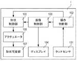
図1は、本発明の第1の実施例であるユーザインターフェース装置の構成を示している。 FIG. 1 shows the configuration of a user interface device according to a first embodiment of the present invention.
タッチセンサ(検出手段)101は、例えば表示装置の表示面に搭載される静電容量型の従来のタッチセンサであり、指先やスタイラスペンのペン先が近接することによる静電容量の変化に基づいて、ユーザ入力を検出する。すなわち、必ずしもディスプレイ104への接触を検出の必須とするものではない。ユーザ入力の検出方法の詳細に関しては後述する。操作判断部102は、タッチセンサ101によるユーザ入力のパターンにより、タッチ操作、スライド操作など、どのような操作かを判断する。操作判断の詳細に関しては後述する。 The touch sensor (detection unit) 101 is, for example, a conventional electrostatic capacitance type touch sensor mounted on the display surface of a display device, and is based on a change in electrostatic capacitance due to the proximity of a fingertip or a stylus pen tip. Detect user input. That is, the contact with the
なお、本明細書中でスライド操作とは、指やタッチペンなどでのタッチ操作によってタッチセンサ101での接触の検出が途切れることなく、かつ、接触を検出している位置が連続的に変化している場合に、スライド操作がなされているものとする。より具体的には、例えば、指やタッチペンなどでディスプレイ104の表面に触れて表面を摺動して移動する状態をスライド操作とする。厳密には、以下の実施例で例示するように、表面に触れなくてもディスプレイ104の表面近傍に指やタッチペンがあることで検出可能である場合もある。従って上述の通り、触覚の検知手段が検出した状態で、その検出が途切れることなく、その検出位置が連続的に変化している場合をスライド操作があったものとする。 Note that in this specification, the sliding operation means that the touch detection by the
画像制御部103は、操作判断部102により判断したユーザ操作に応じて、ディスプレイ104に表示させる画像を制御する。ディスプレイ104は視覚的な方法でユーザとのインターフェースになるように機能し、例えば従来の液晶ディスプレイなどである。 The
形状制御部105は操作判断部102により判断したユーザ操作、及び画像制御部103により制御される画像位置に応じて、形状可変部107のアクチュエータ106を制御する。アクチュエータ106は形状可変部107の形状を変化させる動力部であり、形状可変部107はタッチディスプレイとともに構成され、タッチディスプレイ上に凸部を形成するための部材である。詳細については後述する。 The
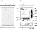
次に、図2を用いて、デジタルカメラ1の外部構成について説明を行う。
図2(a)は、デジタルカメラ1の画像表示機能におけるユーザインターフェースを示している。Next, the external configuration of the
FIG. 2A shows a user interface in the image display function of the
デジタルカメラ1は、ディスプレイ画面10を有しており、該ディスプレイ画面10には、複数の画像表示領域201と、削除ボタン202と、保護ボタン203と、メニューボタン204が構成される。ディスプレイ画面10は、通常平坦な面(第1の形状)をしているが、ユーザに触覚的誘導を与えるために、平坦面の特定領域を凸形状(第2の形状)に変形することが可能なディスプレイ(以下、触覚UIとも記載する)である。本実施例の画像管理機能時は、各ボタンに対して、触覚UIにより表面を凸形状に変形させる。 The
画像表示領域201は、画像管理機能において画像を表示する領域であり、複数の画像表示領域201によりサムネイル表示を行っている。また、画像表示領域201は、画像を選択するタッチ操作、表示する画像群を変更するスライド操作1(スワイプ操作とも呼ばれる)、及び画像を移動させるスライド操作2(ドラッグ操作とも呼ばれる)の入力を受け付けることができる。各操作の詳細については後述する。 The
削除ボタン202は、例えばごみ箱のアイコンが表示されており、選択されている画像を削除する操作を受けつける入力部である。保護ボタン203は、たとえば錠のアイコンが表示されており、選択されている画像を保護する操作を受けつける入力部である。メニューボタン204は、たとえばMenuと表示されており、画像を管理するための機能を選択するメニュー表示を行う操作を受け付ける入力部である。さらに、デジタルカメラ1は、各ボタンに接続されるアクチュエータであるポンプ部206が1つ構成され、触覚UIにより表面を凸形状に変形させることができる。 The
これらのボタンはサムネイル画像を選択したのちに押し込み操作を行う方法に加え、スライド操作2によりサムネイル画像をボタンの上まで移動させる方法でも入力を受け付けることが可能である。 In addition to the method of pressing a thumbnail image and then pressing the button, these buttons can also be input by a method of moving the thumbnail image to above the button by a
また、デジタルカメラ1は、画像管理機能に加え、画像撮影機能や設定変更機能など、様々な機能を有しており、ディスプレイ画面10は、その機能に従って、様々な表示または入力検出、及び触覚UIによる凸形状への変形操作を行う。たとえば図2(b)に示す画像撮影機能におけるユーザインターフェースでは、ディスプレイ画面10全体をライブビュー表示領域として使用し、触覚UIによる凸形状への変形は行わず平面状態に操作する。これにより、ディスプレイ画面10を最大限活用し構図及びカメラの状態を確認することができ、また凸形状による視認性の悪化を防ぐとこができる。 In addition to the image management function, the
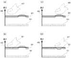
続いて、図3を用いてアクチュエータ106及び形状可変部107の詳細について説明する。
図3は、各ボタンの触覚UIの断面構成を示した図であり、図3(a)は触覚UIが平坦な状態、図3(b)はユーザに触覚的誘導を与えるため、触覚UIを凸形状に変形させた状態を示した図である。なお、図1で説明した内容と同様の構成要素は、同一符号で示し、説明を省略する。Next, details of the
FIG. 3 is a diagram showing a cross-sectional configuration of the tactile UI of each button. FIG. 3A shows a state in which the tactile UI is flat, and FIG. 3B shows tactile UI for giving a tactile guidance to the user. It is the figure which showed the state deformed to convex shape. It should be noted that the same components as those described with reference to FIG.
触覚UIは、透明シート301、透明基板302、空洞部303、タッチセンサ101、ディスプレイ104、アクチュエータであるポンプ部206により構成される。 The tactile UI is composed of a
透明シート(形状可変部)301、空洞部303、ポンプ部206は、以下で説明する形状可変手段を構成する。透明シート301は、伸縮性を有する透明エラストマー材等により形成され、ディスプレイ画面の表面に設けられるとともにディスプレイ画面の略々全面を覆うように配置される。さらに透明シート301は、流動体の導入(加圧)によって空洞部303が拡張すると変形し、流動体の抽出(減圧)によって空洞部303が収縮すると通常の平面状態に戻るように機能する。透明基板302は、透明シート301を支持して空洞部303を少なくとも部分的に規定するように機能する。透明基板302は、好適には硬質である。空洞部303は、流動体を保持し、収縮した体積状態(図3(a)に示す)(第1の状態)と、拡張した体積状態(図3(b)に示す)(第2の状態)を有するように機能する。流動体は、好適には液体であるが、気体またはその他の物質であっても良い。また、空洞部303は流路を介してポンプ部206との連結されている。ポンプ部206は、空洞部303内の流動体の体積を変更するように機能する。すなわち、収縮した体積状態から拡張した体積状態に空洞部303を拡張し、最終的に透明シート301の特定領域(空洞部の上部)を変形させる。空洞部303の体積状態の変更は、ポンプ部206から流動体を追加(流入)、除去(流出)することにより変更する。すなわち、形状制御部105は、ポンプ部206を制御し、変形可能な透明シート301の形状を変えることにより、触覚UIの表面の一部の形状を、各ボタンの領域(表面の一部の領域)の表面形状を該一部の領域以外の領域に対して変化させることができる。 The transparent sheet (shape changing portion) 301, the
以上により、触覚UIは、ディスプレイ画面10上に凸形状を形成することができ、ディスプレイ104により表示する入力グラフィックと併用して用いることで、ユーザにより押下でき、タッチセンサ101上の入力位置を知らせるボタンとして機能する。 As described above, the tactile UI can form a convex shape on the
次に、図4により、タッチセンサ101によるユーザ入力の検出方法について説明する。 Next, a method of detecting a user input by the
図4は、タッチパネル及び触覚UIにおけるユーザ入力とタッチセンサ101の検出閾値との関係を示した図であり、触覚UIの断面構成を示している。図4(a)は凸形状に変形していない場所における、ユーザ入力が検出されない状態を示し、図4(b)は凸形状に変形していない場所における、ユーザ入力が検出される状態を示している。同様に、図4(c)は凸形状に変形した場所における、ユーザ入力が検出されない状態を示し、図4(d)は凸形状に変形した場所における、ユーザ入力が検出される状態を示している。図1及び図3で説明した内容と同様の構成要素は、同一符号で示し、説明を省略する。 FIG. 4 is a diagram showing a relationship between a user input on the touch panel and the tactile UI and a detection threshold value of the
指先401は、ユーザが触覚UIを操作する際の指先であり、触覚UIへの入力操作を示している。 The
検出閾値402は、タッチセンサ101において検出された静電容量の変化量から求めた指先の高さに対して、ユーザ入力を検出するか否かを判定する閾値を示している。
検出閾値402は、触覚UIの全域において、凸形状の高さよりも低く、かつ平坦面よりも高く設定される。指先401の高さが、検出閾値402よりも低い(タッチセンサ101に近い)と、触覚UIが操作されたと認識し、ユーザ入力を検出する。The
The
図4(a)は、触覚UIを指先で触れていない状態を示している。この状態では、指先401は検出閾値402よりも高いため、ユーザ入力は検出されない。図4(b)は、触覚UIの平坦面を指先で触れている状態を示している。この状態では、指先401は検出閾値402よりも低くなるため、触覚UIはユーザ入力を検出する。 FIG. 4A shows a state where the tactile UI is not touched with a fingertip. In this state, since the
図4(c)は、凸形状を指先で触れた状態を示している。この状態では、指先401は透明シート301に触れているものの、検出閾値402よりも高いため、ユーザ入力は検出されない。図4(d)は、凸形状を指先401で押し込んだ状態を示している。この状態では、指先401は検出閾値402よりも低くなるため、触覚UIはユーザ入力を検出する。すなわち、凸形状を形成した領域においては、凸形状を押しこむ操作を行うことで初めてユーザ入力を検出するため、ユーザは従来のボタンと同様の操作感を得ることができる。FIG.4 (c) has shown the state which touched the convex shape with the fingertip. In this state, the
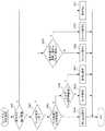
続いて、図5のフローチャートを用いて、操作判断部102によるユーザ入力による操作判断処理について説明を行う。 Next, the operation determination process by the user input by the
S501では指先401の高さが検出閾値402より低いか判断し、低い場合(ユーザ入力があることを検出中である場合)はS502へ、高い場合(ユーザ入力がない場合)はS511へと進む。
S502では操作が継続している間のユーザ入力位置が一定であるか判断し、一定である場合はS503へ、一定でない(移動している、スライドしている)場合はS508へと進む。
S503ではユーザ入力位置が凸形状位置であるかどうか判断し、凸形状位置である場合はS504へ、凸形状位置でない場合はS505へと進む。
S504ではユーザ入力は押し込み操作だと判断し、処理を終了する。
S505では、ユーザ入力がある閾値時間以上経過したか判断し、経過していない場合はS506へ、経過した場合はS507へと進む。
S506ではユーザ入力はタッチ操作だと判断し、処理を終了する。
S507ではユーザ入力は長押し操作だと判断し、処理を終了する。
S508では、直前のユーザ入力が長押し操作かスライド操作2であったか判断し、長押し操作かスライド操作2であった場合はS510へ、長押し操作かスライド操作2でなかった場合はS509へと進む。
S509ではユーザ入力はスライド操作1だと判断し、処理を終了する。
S510ではユーザ入力はスライド操作2だと判断し、処理を終了する。
S511は指の高さが検出閾値内にない場合であり、ユーザ入力が無いと判断できるので、処理を終了する。In step S501, it is determined whether or not the height of the
In S502, it is determined whether the user input position is constant while the operation is continued. If it is constant, the process proceeds to S503, and if it is not constant (moving or sliding), the process proceeds to S508.
In S503, it is determined whether the user input position is a convex position, and if it is a convex position, the process proceeds to S504, and if it is not the convex position, the process proceeds to S505.
In S504, it is determined that the user input is a push-in operation, and the process ends.
In S505, it is determined whether the user input has passed a certain threshold time or more. If not, the process proceeds to S506, and if it has passed, the process proceeds to S507.
In S506, it is determined that the user input is a touch operation, and the process ends.
In step S507, it is determined that the user input is a long press operation, and the process ends.
In S508, the user input immediately before it is determined whether a long press operation or sliding
In step S509, it is determined that the user input is the
In S510, it is determined that the user input is the
S511 is a case where the height of the finger is not within the detection threshold and it can be determined that there is no user input, so the process ends.
以上の処理フローにより、ユーザ入力による操作の判断を最適に行うことが可能となる。 With the above processing flow, it becomes possible to optimally judge the operation by the user input.
ここで、図6〜図8を用いて、画像管理機能の一機能であるスライド操作2による画像の削除について説明を行う。 Here, the deletion of an image by the
図6はスライド操作2による画像の削除についての触覚UIの動作を示すフローチャートである。 FIG. 6 is a flowchart showing the operation of the tactile UI for deleting an image by the
S601ではユーザ操作がスライド操作2であるか判断し、スライド操作2である場合はS602へ、スライド操作2でない場合はS606へ進む。
S602ではユーザの入力位置が削除ボタンの上かどうか判断し、削除ボタンの上である場合はS603へ、削除ボタンでない場合はS605へ進む。
S603ではスライド操作2で選択している画像が保護状態であるか判断し、保護状態である場合はS604へ、保護状態でない場合はS605へ進む。
S604では、削除ボタン部の形状を凸状態に制御し、処理を終了する。これにより、ユーザは削除ボタン部へのスライド操作2が無効であることを触覚で直感的に認知することが可能となる。
S605では、削除ボタン部の形状を平坦状態に制御し、処理を終了する。これにより、ユーザは形状可変部を触覚的に認知することがなく、違和感なく削除ボタン部へのスライド操作2が可能となる。
S606では、タッチ操作で選択している画像が保護状態であるか判断し、保護状態である場合はS607へ、保護状態でない場合はS608へ進む。
S607では、削除ボタン部の形状を平坦状態に制御し、処理を終了する。これにより、ユーザは削除ボタンへの押し込み操作が無効であることを認知することができる。
S608では、削除ボタンの形状を凸状態に制御し、処理を終了する。これにより、ユーザは削除ボタンを押し込みボタンとして使用可能であることを触覚で直感的に認知することが可能となる。また触覚UIは、押し込み操作時にボタンが凹むことで入力を受け付けるため、ユーザは従来のボタンと同様の操作感を得ることができる。In S601, it is determined whether the user operation is the
In S602, it is determined whether or not the input position of the user is above the delete button. If it is above the delete button, the process proceeds to S603, and if it is not the delete button, the process proceeds to S605.
In step S603, it is determined whether the image selected by the
In S604, the shape of the delete button part is controlled to be in a convex state, and the process ends. As a result, the user can intuitively and tactually recognize that the
In step S605, the shape of the delete button unit is controlled to be flat, and the process ends. As a result, the user can perform the
In step S606, it is determined whether or not the image selected by the touch operation is in the protected state. If the image is in the protected state, the process proceeds to step S607. If not, the process proceeds to step S608.
In step S607, the shape of the delete button unit is controlled to be flat, and the process ends. This allows the user to recognize that the push-down operation on the delete button is invalid.
In step S608, the shape of the delete button is controlled to be convex, and the process ends. As a result, the user can intuitively recognize by tactile sense that the delete button can be used as the push button. Further, since the tactile UI receives an input when the button is depressed during the pressing operation, the user can obtain the same operational feeling as the conventional button.
続いて、図7はスライド操作2による画像の削除について、スライド操作2により削除操作を行う画像が保護されていない場合についての触覚UIの動作を示す図である。なお、図2(a)と同様の構成については同符号を付し、説明を省略する。 Next, FIG. 7 is a diagram showing an operation of the tactile UI regarding deletion of an image by the
指先701は、サムネイル画像8の位置であり、スライド操作2の開始位置である。
指先702は、削除ボタン202の位置であり、スライド操作2の終了位置である。The
The
図7(a)はスライド操作2を行う前の状態であり、画像1〜9がサムネイル表示されている。選択されている画像8は保護されていないため、削除ボタン202を含む各ボタンは、凸状態となっている(S608)。 FIG. 7A shows a state before performing the
図7(b)はサムネイル画像8に対してスライド操作2を開始した状態を示す図である。すなわち、サムネイル画像8上でのタッチ操作が閾値時間以上続くと(S505)、長押し操作と判断し(S507)、選択されたサムネイル画像8の枠を強調表示する。その後検出位置が変化すると(S502)、スライド操作2の開始と判断し(S510)、削除ボタン202を含む各ボタンは、平坦な状態に変化する(S605)。 FIG. 7B is a diagram showing a state where the
図7(c)はスライド操作2中を示す図である。すなわち、スライド操作2開始時に選択されたサムネイル画像8が指先701から指先702への移動に追従して表示される。その際、削除ボタン202を含む各ボタンは、サムネイル画像8が保護されていないため、平坦な状態のままである(S605)。 FIG. 7C is a diagram showing the middle of the
図7(d)はスライド操作2終了時の図であり、図7(c)の状態で指を離した際の動作を示す。画像8が削除され、サムネイル表示上に画像8は表示しない。また、選択画像は削除した画像8の次に構成されている画像9となり、画像9が保護されていない場合は、削除ボタン202を含む各ボタンは、凸状態に変化する(S608)。なお、削除を実行する前に、削除を実行して良いかを確認するようにしてもよい。 FIG. 7D is a diagram at the end of the
以上のように、保護されていない画像についてはスライド操作2により快適に削除操作を行うことができる。 As described above, the deletion operation can be comfortably performed by the
続いて、図8はスライド操作2による画像の削除について、スライド操作2により削除操作を行う画像が保護されている場合についての触覚UIの動作を示す図である。なお、構成は図7と同様であるため、同符号を付し、説明を省略する。 Next, FIG. 8 is a diagram showing an operation of the tactile UI regarding deletion of an image by the
図8(a)はスライド操作2を行う前の状態であり、画像1〜9がサムネイル表示されている。選択されている画像8は保護されているため、削除ボタン202を含む各ボタンは、平坦な状態となっている(S607)。 FIG. 8A shows a state before performing the
図8(b)はサムネイル画像8に対してスライド操作2を開始した状態を示す図であり、図7(b)と同等のため説明を省略する。 FIG. 8B is a diagram showing a state in which the
図8(c)はスライド操作2中を示す図である。すなわち、スライド操作2開始時に選択されたサムネイル画像8が指先701から指先702への移動に追従して表示される。その際、削除ボタン202を含む各ボタンは、サムネイル画像8が保護されているため、指先702の位置になると凸状態へと変化する(S604)。 FIG. 8C is a diagram showing the middle of the
図8(d)はスライド操作2終了時の図であり、図8(c)の状態で指を離した際の動作を示す。画像8は保護されているため削除されず、即ちスライド操作2前の図8(a)と同じ状態となる。また、削除ボタン202を含む各ボタンは、平面状態に変化する(S608)。Figure 8 (d) is a diagram at the time of the
以上のように、保護されている画像に対してスライド操作2により削除操作を要求された際に、図8(c)に示すように削除ボタンを凸状態へと変化させることで、ユーザは触覚で直感的に削除操作が無効であることを認知することが可能となる。 As described above, when the
なお、S604において凸状態へと変化させたが、これに限るものではなく、たとえば凸状態と平坦な状態とを定期的に(交互に)繰り返すようにしてもよい。
また、図8(b)において、サムネイル画像8に対してスライド操作2を開始した時点で、操作されている対象のサムネイル画像8は保護されているので、この操作対象に対し無効となる操作(処理)である削除ボタンを凸状態へと変化させるようにしてもよい。すなわち、制御手段は、検出手段によって操作(保護されているサムネイル画像のドラッグ操作)が検出された時点で、その操作による処理が無効となる対象である削除ボタン(無効な処理に対応する位置の形状可変部)の形状を変更してユーザへ通知を行うようにしてもよい。また、ドラッグ操作されている対象を判断して、その対象に対する処理(操作)が無効となるような処理(操作)を示す位置の触覚UI(削除ボタン等)の形状を凸状態へと変化させるようにしてもよい。Although the state is changed to the convex state in S604, the present invention is not limited to this. For example, the convex state and the flat state may be periodically (alternately) repeated.
Further, in FIG. 8B, when the
以上説明したとおり、スライド操作2による削除操作が無効である場合に、触覚的誘導を用いて直感的にユーザへ通知をすることが可能となる。 As described above, when the delete operation by the
なお、本実施例では形状可変部に相当する3つのボタンに対してポンプが1つのみである構成において説明を行ったが、それぞれのボタンに対してポンプを有し、それぞれの形状を独立して変化させることが可能な構成でも同様の効果を奏することができる。その際、S602に示した判断を行わず、スライド操作2により選択された画像が保護状態である場合に、削除ボタンのみを凸状態としてもよい。 In the present embodiment, the description has been given of the configuration in which only one pump is provided for the three buttons corresponding to the shape changing section, but each pump has a pump and each shape is independent. The same effect can be obtained even with a configuration that can be changed by changing. At that time, if the image selected by the
また、例えば、本実施例においてはディスプレイが平坦である場合の説明を行ったが、これに限るものではなく、湾曲している表面に変形部材を構成したユーザインターフェース装置においても同様の効果を奏することができる。 Further, for example, although the case where the display is flat has been described in the present embodiment, the present invention is not limited to this, and a user interface device in which a deformable member is formed on a curved surface also exhibits the same effect. be able to.
また、触覚UIの形状を変化させる構成として、空洞部に流動体を流入する例を用いて説明したが、これに限られる訳ではなく、表面の形状を変化させユーザに触覚的誘導を与えられる構成であれば何でもよい。さらには、形状変化として凸形状を例にあげて説明をしたがこれに限られることはなく、凹状態や凸凹状態、また電気的特性により表面の摩擦係数を変化させる構成においても同様の効果を得ることができる。 Further, although the configuration in which the shape of the tactile UI is changed has been described by using the example in which the fluid flows into the cavity, the present invention is not limited to this, and the shape of the surface can be changed to give a tactile guidance to the user. Any configuration is acceptable. Furthermore, the convex shape has been described as an example of the shape change, but the present invention is not limited to this, and the same effect can be obtained in a concave state, an irregular state, or a configuration in which the friction coefficient of the surface is changed according to electrical characteristics. Obtainable.
また、本実施例において、ユーザの入力を検出する構成として、静電容量型のタッチセンサのみでタッチ操作、長押し操作、スライド操作1、スライド操作2、押し込み操作を判別する例について説明したが、これに限られる訳ではない。例えば、静電容量型のタッチセンサに加えて、空洞部に圧電センサを構成し、ユーザが凸形状を押し込むことによる空洞部内の圧力の変化を検出し、ユーザの押込み操作を検出するようにしても良い。 Further, in the present embodiment, an example in which a touch operation, a long press operation, a
続いて、以下、図9〜図13を参照して、本発明の第2の実施例による、操作装置(ユーザインターフェース装置)について説明する。本実施例では、ユーザインターフェース装置の一例として、撮像装置であるデジタルカメラ2の画像表示機能のユーザインターフェースを例にとって説明する。 Subsequently, an operation device (user interface device) according to a second embodiment of the present invention will be described below with reference to FIGS. 9 to 13. In the present embodiment, as an example of the user interface device, a user interface having an image display function of the
図9は、本発明の第2の実施例であるユーザインターフェース装置の構成を示している。なお、図1と同様の構成については同符号を付し、説明を省略する。
形状制御部905は実施例1とは異なる判断にて動作するため別符号を付す。
アクチュエータ906及び形状可変部907は、実施例1におけるアクチュエータ106及び形状可変部107と異なるため別符号を付す。これらの詳細については後述する。FIG. 9 shows the configuration of the user interface device according to thesecond embodiment of the present invention. The same components as those in FIG. 1 are designated by the same reference numerals and the description thereof will be omitted.
The
Since the
次に、図10を用いて、デジタルカメラ2の外部構成及び画像表示機能時の動作について説明を行う。 Next, the external configuration of the
図10(a)に示すように、デジタルカメラ2のディスプレイ画面20にタッチセンサ101とディスプレイ104は重なって構成され、略々全面に形状可変部907が構成されている。具体的には縦に5か所、横に7か所の、計35か所に形状可変部907を有し、左上から右に907a1、907b1、・・・、907g1、また下に907a1、907a2、・・・、907a5とする。すなわち、右下の形状可変部は907g5となる。また、デジタルカメラ2は形状可変部907ごとにアクチュエータ906であるポンプを有し、形状制御部905はそれぞれのアクチュエータ(ポンプ)906を用いて、それぞれの形状変形部の形状を、独立して制御することが可能である。 As shown in FIG. 10A, the
即ち、実施例1との差異としては、ディスプレイ画面20の略々全面に形状可変部907が構成されていることと、形状制御部905はそれぞれの形状変形部の形状を、独立して制御することが可能であることが挙げられる。 That is, the difference from the first embodiment is that the
以上のように、ディスプレイ画面20は、通常平坦な面をしているが、ユーザに触覚的誘導を与えるために、平坦面の特定領域を凸形状に変形することが可能なディスプレイ(以下、触覚UIとも記載する)である。本実施例の画像表示機能時は、各ボタン(複数の領域から構成される一部の領域)に対して、触覚UIにより表面を凸形状に変形させる。 As described above, the
デジタルカメラ2における画像表示機能は、図10(a)に示すように、ディスプレイ画面20全体に画像が表示される。そして、たとえば左右方向へのスライド操作1で表示画像を次の画像、前の画像へと切り替える動作を行う。 With the image display function of the
また、図10(b)はデジタルカメラ2で撮影した画像が保存されている構成を示す。デジタルカメラ2は撮影した画像をグループごとにまとめて保存しており、撮影時にどのグループに保存するか、画像撮影機能時のメニューにて切り替えが可能である。画像表示機能時には、Photo0101の次がPhoto0102、さらに次がPhoto0201、のように、スライド操作1により次の画像が要求された際には、グループを超えて順次表示を行う。 Further, FIG. 10B shows a configuration in which an image taken by the
なお、画像表示機能時には、形状可変部907は通常、平坦な状態となっている。これは、形状が変化していると画像の視認性が悪くなるためである。一方、デジタルカメラ2は、画像表示機能以外の機能である場合に、凸形状をボタンとして使用する。例えば、実施例1で示した画像管理機能時には各ボタンに合わせて凸形状を形成する。 Note that the
アクチュエータ906及び形状可変部907の構造の詳細については実施例1の図3と同等であるため説明を省略する。 The details of the structures of the
また、タッチセンサ101によるユーザ入力の検出方法についても実施例1の図4と同等であるため説明を省略する。 Further, the method of detecting the user input by the
また、操作判断部102によるユーザ入力による操作判断処理についても実施例1の図5と同等であるため説明を省略する。 Further, the operation determination process by the user input by the
続いて、図11、図12を用いて画像表示機能時の画像変更について説明を行う。 Subsequently, the image change at the image display function will be described with reference to FIGS. 11 and 12.
図11はスライド操作1による画像の切り替えについての触覚UIの動作を示すフローチャートである。 FIG. 11 is a flowchart showing the operation of the tactile UI for switching the image by the
S1101ではユーザ操作がスライド操作1であるか判断し、スライド操作1である場合はS1102へ、スライド操作1でない場合はS1104へ進む。
S1102では切り替える前後の画像のグループが同一か判断し、同一でない場合はS1103へ、同一である場合はS1104へ進む。
S1103では、全ての形状可変部を凸状態にし、処理を終了する。
S1104では、全ての形状可変部を平坦な状態にし、処理を終了する。User operation in S1101, it is determined whether the
In S1102, it is determined whether the image groups before and after switching are the same. If they are not the same, the process proceeds to S1103. If they are the same, the process proceeds to S1104.
In S1103, all the shape variable parts are made to be in a convex state, and the processing is ended.
In S1104, all the shape variable parts are made flat, and the process ends.
以上のフローチャートにより、スライド操作1による画像切り替え時にグループをまたいで画像が切り替わった際に、ディスプレイ画面20の略全面に配置されている形状可変部907が凸形状へと変化する(S1103)。また、スライド操作1が終了すると、全ての形状可変部を平坦にし(S1104)、画像の視認性低下を防ぐことができる。 According to the above flow chart, when the images are switched over the groups when the images are switched by the
図12はユーザによる画像変更を要求するスライド操作1を示す。なお、図10(b)と同様の構成については同符号を付し、説明を省略する。
図12(a)はスライド操作1を上面から示した図である。FIG. 12 shows a
FIG. 12A is a diagram showing the
指先1201は、スライド操作1の開始位置であり、指先1202は、スライド操作1の終了位置である。また軌跡1203は、スライド操作1時の指先の軌跡である。指先1202は指先1201よりも左側に位置しており、操作判断部はスライド操作1の方向が左方向であることから、次の画像へと切り替える操作であると判断する。 The
図10(b)で示した保存画像の構成において、現在Photo0101が表示されているときに、図12(a)で示す左スライド操作1が実行された場合、Photo0102が表示される。その際、Photo0101とPhoto0102のグループが同一であるため(S1102)、図12(b)で示す断面図のように、形状可変部は平坦な状態のままとなる(S1104)。 In the configuration of the saved image shown in FIG. 10B, when the
続いて、さらに図12で示す左スライド操作1が実行された場合、Photo0201が表示される。その際、Photo0102とPhoto0201のグループが異なるため(S1102)、図12(c)で示す断面図のように、形状可変部はスライド操作1の間、凸形状となる(S1103)。 Subsequently, when the
すなわち、軌跡1203上に位置している形状可変部907a3〜907e3も凸形状となり、これにより、スライド操作1中にユーザが凹凸を感じることができ、触覚的誘導により直感的にグループが変化したことを知ることができる。 That is, the shape changing parts 907a3 to 907e3 located on the
なお、本実施例では形状変化部すべてを凸形状とすることで通知を行ったが、これに限ることはなく、スライド操作1の速度及び方向から、今後指先が通過する軌跡を推定し、その軌跡に応じた形状可変部のみを凸形状としてもよい。即ち、指先1201から左方向にスライド操作1があることを検出した際に、図13(a)に示すように、今後指先が通過する形状可変部907a3〜907e3のみを凸形状とし、その周囲については平坦な形状としてもよい。また、軌跡を厳密に推定することは難しいため、図13(b)に示すように、指先1201の位置から、スライド操作1の方向の上下一定角度以内にある形状可変部のみを凸形状とし、その周囲については平坦な形状としてもよい。またさらには、図13(c)に示すように、スライド操作1の方向に加え、スライド操作1の速度に応じて、現在の指先の位置からある時間T内に到達する距離にある形状可変部のみを凸形状とし、その周囲については平坦な形状としてもよい。この時間Tとは、形状可変部の形状を平坦な状態から凸状態へと変化させるために必要な時間から算出される。さらには、スライド操作1中常に凹凸により通知を行う必要はなく、図13(d)に示すように、1か所のみ凸形状とすることでもユーザへ通知を行うことが可能である。 In addition, in the present embodiment, the notification is made by making all the shape changing parts convex, but the present invention is not limited to this, and the trajectory through which the fingertip will pass is estimated from the speed and direction of the
また、保存するフォルダが変化した際に形状を変化させてユーザに通知を行ったが、これに限ることはなく、たとえば次のようなタイミングで通知を行ってもよい。すなわち、写真に記録されている撮影日やGPS位置情報、使用したレンズ情報等が変化したとき、画像の最後でさらに次の画像へと切り替える操作が発生したとき、画像のサイズや形式が変化したとき、等である。 Although the shape is changed and the user is notified when the folder to save is changed, the present invention is not limited to this, and the notification may be performed at the following timing, for example. That is, when the shooting date, GPS position information, used lens information, etc. recorded in the photograph change, or when an operation for switching to the next image occurs at the end of the image, the size or format of the image has changed. And so on.
また、次の画像が動画である場合には毎回通知を行ってもよい。動画の場合ユーザは再生を実行する必要があるが、静止画と動画が混在して保存されている場合、表示している画像が動画か否か判断する必要がある。そこで、動画である場合は触覚的誘導によりユーザに通知を行うことで、ユーザは瞬時に、次に表示される画像が動画であることを認知することができる。さらには、動画である場合、凸形状を生成してユーザに通知を行った後に形状可変部を平坦状態へと戻さずに、凸形状を動画の再生を促す押し込みボタンとして利用することもできる。 Further, when the next image is a moving image, the notification may be given every time. In the case of a moving image, the user needs to execute reproduction, but when a still image and a moving image are mixedly stored, it is necessary to determine whether or not the displayed image is a moving image. Therefore, in the case of a moving image, by notifying the user by tactile guidance, the user can instantly recognize that the image displayed next is a moving image. Furthermore, in the case of a moving image, it is possible to use the convex shape as a push button for promoting the reproduction of the moving image without generating the convex shape and notifying the user and then returning the variable shape portion to the flat state.
さらには、複数の要因で通知を行いたい場合、凹凸のパターンを変化させてもよい。例えばグループが変わるときには図13(d)に示すような1か所のみの凸形状による通知を行い、最後の画像で次の画像がない時には全面を凸形状にして通知を行うこともできる。 Furthermore, when it is desired to notify by a plurality of factors, the uneven pattern may be changed. For example, when the group is changed, it is also possible to notify by using only one convex shape as shown in FIG. 13D, and when the last image has no next image, the entire surface may be convex and the notification may be performed.
また、複数位置のスライド操作による写真の拡大、縮小が可能な場合、例えば最大サイズで表示している際にさらに拡大を要求する操作がなされた際にも、形状を変化させてユーザに通知を行ってもよい。 In addition, if the photo can be enlarged or reduced by a slide operation at multiple positions, for example, even when an operation that requires further enlargement is performed when the image is displayed at the maximum size, the shape is changed and the user is notified. You can go.
なお、本実施例ではデジタルカメラの画像表示機能を例に挙げて説明を行ったが、これに限ることはなく、さまざまな製品の、さまざまな機能において同様の効果を奏することができる。 Although the image display function of the digital camera has been described as an example in the present embodiment, the present invention is not limited to this, and similar effects can be obtained in various functions of various products.
例えば携帯情報端末の文書データ表示機能時にも同様の効果を奏することができる。その場合は、例えば次のようなタイミングで通知を行うことが考えられる。すなわち、文章の最初や最後になった際、次の文章へ切り替わった際、文章内の章が切り替わった際、文章内に動画やアニメーションが埋め込まれている際、などが挙げられる。 For example, the same effect can be obtained even when the document data display function of the portable information terminal is used. In that case, for example, the notification may be performed at the following timing. That is, when the sentence is at the beginning or end, when it is switched to the next sentence, when a chapter in the sentence is switched, when a moving image or animation is embedded in the sentence, and the like.
また、例えば、本実施例においてはディスプレイが平坦である場合の説明を行ったが、これに限るものではなく、湾曲している表面に変形部材を構成したユーザインターフェース装置においても同様の効果を奏することができる。 Further, for example, although the case where the display is flat has been described in the present embodiment, the present invention is not limited to this, and a user interface device in which a deformable member is formed on a curved surface also exhibits the same effect. be able to.
また、触覚UIの形状を変化させる構成として、空洞部に流動体を流入する例を用いて説明したが、これに限られる訳ではなく、表面の形状を変化させユーザに触覚的誘導を与えられる構成であれば何でもよい。さらには、形状変化として凸形状を例にあげて説明をしたがこれに限られることはなく、凹状態や凸凹状態、また電気的特性により表面の摩擦係数を変化させる構成においても同様の効果を得ることができる。 Further, although the configuration in which the shape of the tactile UI is changed has been described by using the example in which the fluid flows into the cavity, the present invention is not limited to this, and the shape of the surface can be changed to give a tactile guidance to the user. Any configuration is acceptable. Furthermore, the convex shape has been described as an example of the shape change, but the present invention is not limited to this, and the same effect can be obtained in a concave state, an irregular state, or a configuration in which the friction coefficient of the surface is changed according to electrical characteristics. Obtainable.
このように、形状制御部(制御手段)は、タッチセンサへの操作による装置への指令(スライド操作での次の画像への移動など)に対する指令先からの応答(画像情報の変化など)に応じて、形状可変部の形状を変更してユーザへ通知する。 In this way, the shape control unit (control means) responds to a command (such as moving to the next image by a sliding operation) to the device by operating the touch sensor from a command destination (such as a change in image information). Accordingly, the shape of the shape changing unit is changed and the user is notified.
また、本実施例において、ユーザの入力を検出する構成として、静電容量型のタッチセンサのみでタッチ操作、スライド操作、押し込み操作を判別する例について説明したが、これに限られる訳ではない。例えば、静電容量型のタッチセンサに加えて、空洞部に圧電センサを構成し、ユーザが凸形状を押し込むことによる空洞部内の圧力の変化を検出し、ユーザの押込み操作を検出するようにしても良い。 In addition, in the present embodiment, an example in which a touch operation, a slide operation, and a push operation are discriminated by only a capacitance type touch sensor has been described as a configuration for detecting a user input, but the present invention is not limited to this. For example, in addition to the capacitance type touch sensor, a piezoelectric sensor is configured in the cavity, and the change in the pressure in the cavity caused by the user pushing the convex shape is detected and the pushing operation by the user is detected. Is also good.
続いて、以下、図14〜図16を参照して、本発明の第3の実施例による、操作装置(ユーザインターフェース装置)について説明する。本実施例では、ユーザインターフェース装置の一例として、携帯情報端末(PDA:Personal Digital Assistant)3のデジタルカメラ遠隔操作機能のユーザインターフェースを例にとって説明する。 Subsequently, an operation device (user interface device) according to a third embodiment of the present invention will be described below with reference to FIGS. 14 to 16. In this embodiment, a user interface of a digital camera remote control function of a personal digital assistant (PDA) 3 will be described as an example of the user interface device.
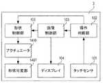
図14は、本発明の第3の実施例であるユーザインターフェース装置の構成を示している。なお、図1と同様の構成については同符号を付し、説明を省略する。
アクチュエータ1406及び形状可変部1407は、他の実施例におけるアクチュエータ及び形状可変部と異なる構造のため別符号を付す。これらの詳細については後述する。
なお、不図示のデジタルカメラとの接続は、無線でもよいし、有線でもよい。FIG. 14 shows the configuration of the user interface device according to the third embodiment of the present invention. The same components as those in FIG. 1 are designated by the same reference numerals and the description thereof will be omitted.
The
The connection with a digital camera (not shown) may be wireless or wired.
次に、図15を用いて、携帯情報端末3の外部構成及びデジタルカメラ遠隔操作機能の例を示す。 Next, an example of the external configuration of the
図15(a)に示すように、携帯情報端末3のディスプレイ画面30にタッチセンサ101とディスプレイ104は重なって構成され、全面に形状可変部1407が構成されている。そして、形状可変部1407により、ディスプレイ画面30の任意の位置の形状を可変し、凸部を生成することが可能である。詳細については後述する。 As shown in FIG. 15A, the
携帯情報端末3におけるデジタルカメラ遠隔操作機能の例を、図15(b)に示す。
カメラ画像表示エリア1501は、接続しているデジタルカメラが撮影している映像を表示するエリアである。また、カメラ画像表示エリア1501内の任意の場所をタッチすることで、フォーカスエリアを設定し、またその場所にフォーカスを合わせるオートフォーカス操作を実行することができる。An example of the digital camera remote control function in the
The camera
カメラ情報表示エリア1502はカメラに設定されている情報を表示するエリアであり、撮影モードやデジタルカメラの電池の残量、撮影可能枚数等を表示する。 The camera
メニューボタン1503はデジタルカメラや携帯情報端末3のデジタルカメラ遠隔操作機能に関する様々な設定変更を行うためのメニューを表示させるボタンである。 The
ズーム操作エリア1504はデジタルカメラのズーム操作を携帯情報端末3から遠隔で操作するためのエリアである。ユーザは、スライダー1504aをタッチ操作により選択したのち、そのままスライドバー1504bに沿って上下にスライド操作を行うことで、ズームの操作が可能である。操作ガイド部1504cは、通常平面状態であり、スライダー1504aを選択した際に凸状態へと変化することで、スライダー1504aをスライドバー1504bに沿って操作しやすくするためのガイド部である。また、表示バー1504dは全域の相対的なズーム位置を表示する表示部である。ズーム操作についての詳細は後述する。 The
フォーカス操作エリア1505はデジタルカメラのフォーカス操作を携帯情報端末3から遠隔で操作するためのエリアであり、+ボタン1505a、−ボタン1505b、及びスライダー1505cを用いての操作が可能となっている。+ボタン1505a、−ボタン1505bはタッチ操作に加え、長押し操作により連続的に操作が可能となっている。また、スライダー1505c及びスライドバー1505dは、フォーカス全域の相対的なフォーカス位置として、右側が無限側、左側が至近側を示す。さらに、スライダー1505cをタッチ操作により選択したのち、そのままスライドバー1505dに沿って左右にスライド操作を行うことで、フォーカス操作を行うこともできる。また、操作ガイド部1505eは、ズームの操作ガイド部1504cと同様であるため説明を省略する。フォーカス操作の詳細については後述する。 The
自動露出設定エリア1506はデジタルカメラの自動露出設定を携帯情報端末3から遠隔で設定するためのエリアであり、+ボタン1506a、−ボタン1506b、を用いての設定が可能となっている。 The automatic
画像評価値表示エリア1507は、画像の評価値を表示するエリアであり、例えばコントラスト評価値や、ベクトルスコープ評価値等である。また、設定されたフォーカスエリアの拡大画像であってもよい。 The image evaluation
レリーズボタン1508は遠隔で操作しているデジタルカメラのレリーズを行うボタンである。レリーズボタン1508は凸形状を成し、押し込み操作によりレリーズを行う。
デジタルカメラ遠隔操作機能において、通常時はレリーズボタン1508が凸形状を成し、その他のボタンやエリアは平面状態となっている。A
In the digital camera remote control function, normally, the
続いて、図16を用いてアクチュエータ1406及び形状可変部1407の詳細について説明する。 Next, details of the
図16は、各ボタンの触覚UIの断面構成を示した図であり、図16(a)は触覚UIが平坦な状態、図16(b)はユーザに触覚的誘導を与えるため、触覚UIを凸形状に変形させた状態を示した図である。なお、図3で説明した内容と同様の構成要素は、同一符号で示し、説明を省略する。 FIG. 16 is a diagram showing a cross-sectional structure of the tactile UI of each button. FIG. 16A shows a state in which the tactile UI is flat, and FIG. 16B shows tactile UI for giving tactile guidance to the user. It is the figure which showed the state deformed to convex shape. The same components as those described with reference to FIG. 3 are designated by the same reference numerals, and the description thereof will be omitted.
触覚UIは、透明シート301、伸縮素材1602、電極1603、タッチセンサ101、ディスプレイ104により構成される。1602は電気信号により伸縮する透明な伸縮素材であり、アクチュエータ906と形状可変部907を兼ねる。1603は伸縮素材1602に電気信号を伝達する電極であり、透明であることが望ましい。 The tactile UI is composed of a
図16(a)は電極1603により、伸縮素材1602が収縮する信号を出力している状態であり、ディスプレイ画面上が平坦となっている。一方、図16(b)は電極1603により、伸縮素材1602のうちの1602a、1602b、1602cに対して、膨張する信号を出力している状態であり、ディスプレイ上に凸部が生成されている。 FIG. 16A shows a state in which a signal for contracting the
さらに、携帯情報端末3は、伸縮素材1602がディスプレイ画面上に二次元に配置されており、形状制御部105は電極1603を用いて伸縮素材1602ごとに伸縮を制御可能である。 Further, in the
以上により、触覚UIは、ディスプレイ画面30上の任意の位置、任意の形状、任意の大きさで凸形状を形成することが可能である。さらには、伸縮素材1602はそれぞれのサイズが小さい方が望ましく、ディスプレイの画素サイズ以下であれば、画面上の画像と一致して凸部を生成することが可能となる。そして、ディスプレイ画面30により表示する入力グラフィックと併用して用いることで、ユーザにより押下でき、タッチセンサ101上の入力位置を知らせるボタンとして機能する。 As described above, the tactile UI can form a convex shape at any position, any shape, and any size on the
なお、タッチセンサ101によるユーザ入力の検出方法、及び操作判断部102によるユーザ入力による操作判断処理については、それぞれ実施例1の図4、図5と同等であり、説明を省略する。 The method of detecting a user input by the
次に、フォーカスの+ボタン1505a操作における携帯情報端末3のデジタルカメラ遠隔操作機能のユーザインターフェース動作についての説明を行う。 Next, the user interface operation of the digital camera remote control function of the
フォーカスの+ボタン1505aは通常平坦状態となっている。そして、ユーザは+ボタン1505aを長押し操作している時間に応じて、フォーカスの位置指令を無限側へと更新し、遠隔操作しているデジタルカメラのフォーカスを無限側へ操作することができる。また、駆動したフォーカスの全域に対する相対的な位置はスライダー1505cによって表示される。 The focus +
ここで、フォーカスが無限端へと駆動してもなお+ボタン1505aを長押し操作している場合、+ボタン1505aの形状を凸状態へと変形させる。これにより、フォーカスがユーザの操作に応じて動作することができないことを、操作を行っている指先に対して触覚的誘導により通知を行うことができる。
なお、フォーカスの−ボタン1505bや自動露出設定エリア1506でも同等である。Here, even if the focus is driven to the infinite end, if the +
The same applies to the focus minus
続いて、ズームのスライダー操作における携帯情報端末3のデジタルカメラ遠隔操作機能のユーザインターフェース動作についての説明を行う。 Next, the user interface operation of the digital camera remote control function of the
ズーム操作エリアのスライダー1504aがスライドバー1504bの中心にあると停止していることを示し、スライダー1504aを上方向へと操作すると、ズームが望遠方向に、下方向へと操作すると、ズームが広角方向に駆動する。即ち、スライドバー1504b上の任意の位置へスライド操作を行うことで、スライダー1504aが操作位置に移動し、操作位置に応じてズーム駆動のための速度指令を、操作時間だけ出力する。これにより、操作位置に応じて駆動速度が変化し、スライダー1504aが中心に近いほど低速で、中心から離れた位置まで操作すると高速でズームが駆動する。さらに、スライド操作によりズームを操作中に指を離すと、スライダー1504aがスライドバー1504bの中心に戻り、ズームの駆動が停止する。 When the
ここで、ズームのスライダー1504a、スライドバー1504b、及び操作ガイド部1504cは通常平坦状態となっている。そして、ユーザがスライダー1504aをタッチ操作により選択すると、操作ガイド部1504cが凸状態へと変化させる。これにより、スライドバー1504bを囲うように凸形状が生成され、スライド操作にてズーム操作可能な範囲を、操作を行っている指先に対して触覚的誘導により通知を行うことができる。また、操作が無効となる方向に凸形状を生成することで、ユーザが操作しづらくなるので、より快適にズームを操作することができる。 Here, the
またさらには、スライドバー1504bの中心も凸形状を成すことで、逆方向への操作へと切り替わる位置を触覚的誘導により通知してもよい。 Furthermore, the center of the
また、スライダー1504aを上方へと操作し望遠側へズームを操作していて、ズームが望遠端に達した場合、フォーカスの+ボタン操作で説明したのと同様に、スライダー1504aを凸形状に変形させてもよい。すなわち、スライダー1504aは指先に追従して移動するため、指先の位置が凸形状に変化することとなる。これにより、ズームがユーザの操作に応じて動作することができないことを、操作を行っている指先に対して触覚的誘導により通知を行うことができる。なお、広角側への操作の場合も同様である。 When the
また、フォーカス操作エリアのスライダー操作における操作ガイド部1505eについても、ズーム操作エリアの操作ガイド部1504cと同様であるため説明を省略する。 Further, the
このように、形状制御部(制御手段)は、タッチセンサへの操作による装置への指令(スライド操作でのズーム・フォーカスの位置操作など)に対する指令先(デジタルカメラ)からの応答(可動端であることなど)に応じて、形状可変部の形状を変更してユーザへ通知する。 As described above, the shape control unit (control means) responds to a command (a zoom / focus position operation by slide operation, etc.) from the command destination (digital camera) to the device by operating the touch sensor (at the movable end). The shape of the variable shape part is changed and the user is notified.
以上説明したとおり、形状可変部を凸形状にすることで、ユーザへの触覚的誘導による通知として機能させることができる。形状可変部による凸形状をボタンとして機能させるだけではなく、ユーザへの触覚的誘導による通知として機能させることで、さらに表現豊かな触覚UIを提供することが可能となる。 As described above, by making the shape variable portion convex, it is possible to function as a notification by tactile guidance to the user. It is possible to provide a more expressive tactile UI by not only functioning the convex shape of the shape changing unit as a button but also functioning as a notification by tactile guidance to the user.
また、本実施例では携帯情報端末のデジタルカメラ遠隔操作機能について説明を行ったが、これに限ることはなく、さまざまな機器のさまざまな機能において、同様の効果を奏することができる。例えば監視カメラの遠隔操作機におけるパン、チルトの操作においてもズームやフォーカスの操作と同様の動作を行うことで、同様の効果を奏することができる。 Further, although the digital camera remote control function of the portable information terminal has been described in the present embodiment, the present invention is not limited to this, and similar effects can be obtained in various functions of various devices. For example, the same effect can be obtained by performing the same operation as the zoom and focus operations in the pan and tilt operations in the remote operation device of the surveillance camera.
なお、例えば、本実施例においてはディスプレイが平坦である場合の説明を行ったが、これに限るものではなく、湾曲している表面に変形部材を構成したユーザインターフェース装置においても同様の効果を奏することができる。 Note that, for example, although the case where the display is flat has been described in the present embodiment, the present invention is not limited to this, and a user interface device having a deformable member on a curved surface also exhibits the same effect. be able to.
また、触覚UIの形状を変化させる構成として、電気信号により伸縮可能な素材を用いる例について説明したが、これに限られる訳ではなく、表面の形状を変化させユーザに触覚的誘導を与えられる構成であれば何でもよい。さらには、形状変化として凸形状を例にあげて説明をしたがこれに限られることはなく、凹状態や凸凹状態、また電気的特性により表面の摩擦係数を変化させる構成においても同様の効果を得ることができる。 Also, as the configuration for changing the shape of the tactile UI, an example of using a material that can be expanded and contracted by an electric signal has been described, but the invention is not limited to this, and a configuration in which the surface shape is changed and tactile guidance can be given to the user. Anything will do. Furthermore, the convex shape has been described as an example of the shape change, but the present invention is not limited to this, and the same effect can be obtained in a concave state or an irregular state, or in a configuration in which the friction coefficient of the surface is changed depending on the electrical characteristics. Obtainable.
また、本実施例において、ユーザの入力を検出する構成として、静電容量型のタッチセンサのみでタッチ操作、スライド操作1、押し込み操作を判別する例について説明したが、これに限られる訳ではない。例えば、静電容量型のタッチセンサに加えて、押し込み操作により電極に流れる逆起電流を検知しても良い。 Further, in the present embodiment, as the configuration for detecting the input of the user, the example in which the touch operation, the
以上、本発明の好ましい実施形態について説明したが、本発明はこれらの実施形態に限定されず、その要旨の範囲内で種々の変形及び変更が可能である。 Although the preferred embodiments of the present invention have been described above, the present invention is not limited to these embodiments, and various modifications and changes can be made within the scope of the gist thereof.
101 タッチセンサ(検出手段)
105 形状制御部(制御手段)
301 透明シート(形状可変部、形状可変手段)
303 空洞部(形状可変手段)
106 ポンプ(形状可変手段)101 touch sensor (detection means)
105 Shape control unit (control means)
301 transparent sheet (shape changing part, shape changing means)
303 Cavity (shape changing means)
106 Pump (shape changing means)
Claims (11)
Translated fromJapanese前記端末の表面への操作を検出する検出部と、
前記表面に配置され、形状が可変に構成された形状可変部と、
前記表面に表示を行うディスプレイと、
前記ディスプレイによって前記表面内の場所に表示されたアイコンの機能が、前記ディスプレイによって表示されたオブジェクトであって、前記アイコンへドラッグされたオブジェクトまたはドラッグされるオブジェクトに対しては許可されていない場合、前記表面内の前記場所が変形するように、前記検出部によって検出された操作に基づいて、前記形状可変部の制御を行う制御部と、
を有することを特徴とする端末。A terminal,
A detection unit that detects an operation on the surface of the terminal,
A shape changing portion arranged on the surface and having a variable shape;
A display for displaying on the surface,
If the function of the icon displayed at the location in the surface by the display is not allowed for the object displayed by the display and dragged or dragged to the icon, A control unit that controls the shape changing unit based on an operation detected by the detection unit so that the place in the surface is deformed,
A terminal characterized by having.
前記撮像装置は、撮像光学系と、前記撮像光学系から受光する撮像素子と、を有する、
ことを特徴とする請求項1ないし請求項3のうちいずれか1項に記載の端末。The terminal is an imaging device,
The image pickup device includes an image pickup optical system and an image pickup element that receives light from the image pickup optical system.
The terminal according to claim 1, wherein the terminal is a terminal.
前記端末の表面へのスライド操作を検出する検出部と、
前記表面に配置され、形状が可変に構成された形状可変部と、
前記形状可変部の制御を行う制御部と、
を有し、
前記制御部は、第1形状と前記第1形状とは異なる第2形状とに空間的に交互に前記形状可変部が形成されるようにして、前記検出部により検出された操作に対応する処理の無効性に関して、ユーザに情報を与える、
ことを特徴とする端末。A terminal,
A detection unit that detects aslide operation on the surface of the terminal,
A shape changing portion arranged on the surface and having a variable shape;
A control unit for controlling the shape changing unit,
Have
The control unit performs processing corresponding to an operation detected by the detection unit such that the shape changing unit isspatially alternately formed in a first shape and a second shape different from the first shape. Informs the user about the invalidity of
A terminal characterized by that.
前記制御部は、前記ディスプレイにより前記場所に表示されたアイコンに基づいて、該場所での前記形状可変部が前記第1形状と前記第2形状とに空間的に交互に形成されるようにする、
ことを特徴とする請求項6に記載の端末。A display for displaying on the surface,
The control unit causes the shape variable unit at the location to bespatially alternately formed into the first shape and the second shape based on an icon displayed at the location by the display. ,
The terminal according to claim6 , wherein the terminal is a terminal.
前記端末の表面への操作を検出する検出部と、
前記表面に配置され、形状が可変に構成された形状可変部と、
前記形状可変部の制御を行う制御部と、
前記表面に表示を行うディスプレイと、
を有し、
前記制御部は、前記検出部により検出された、ある場所への操作と、前記ディスプレイにより前記場所に表示されたアイコンとに基づいて、前記ディスプレイにより表示されたオブジェクトがドラッグされた前記アイコンの機能が前記オブジェクトに対して許可されていない場合、前記場所での前記形状可変部が第1形状と前記第1形状とは異なる第2形状とに交互に形成されるようにして、前記検出部により検出された操作に対応する処理の無効性に関して、ユーザに情報を与える、
ことを特徴とする端末。A terminal,
A detection unit that detects an operation on the surface of the terminal,
A shape changing portion arranged on the surface and having a variable shape;
A control unit for controlling the shape changing unit,
A display for displaying on the surface,
Have
The control unit is a function of the icon in which the object displayed on the display is draggedbased on an operation to a certain place detected by the detection unit and an icon displayed on the place on the display. If is not allowed for the object,as the deformable portion inthe locations are alternately formed in adifferent secondshape and thefirst shapefirstshape,the detecting unit Informs the user about the invalidity of the process corresponding to the operation detected by
Terminal, characterized in that.
受光を行う撮像素子と、
前記撮像装置のユーザインターフェースとして機能する請求項1ないし請求項10のうちいずれか1項に記載の端末と、
を有することを特徴とする撮像装置。An imaging device,
An image sensor that receives light,
The terminal according to any one of claims 1 to10 , which functions as a user interface of the imaging device,
An image pickup apparatus comprising:
Priority Applications (3)
| Application Number | Priority Date | Filing Date | Title |
|---|---|---|---|
| JP2015214419AJP6685695B2 (en) | 2015-10-30 | 2015-10-30 | Terminal and imaging device |
| US15/298,613US10444839B2 (en) | 2015-10-30 | 2016-10-20 | Terminal, and image pickup apparatus including the same |
| US16/562,905US20190391657A1 (en) | 2015-10-30 | 2019-09-06 | Terminal, and image pickup apparatus including the same |
Applications Claiming Priority (1)
| Application Number | Priority Date | Filing Date | Title |
|---|---|---|---|
| JP2015214419AJP6685695B2 (en) | 2015-10-30 | 2015-10-30 | Terminal and imaging device |
Related Child Applications (1)
| Application Number | Title | Priority Date | Filing Date |
|---|---|---|---|
| JP2019107800ADivisionJP6799637B2 (en) | 2019-06-10 | 2019-06-10 | Terminal and imaging device |
Publications (3)
| Publication Number | Publication Date |
|---|---|
| JP2017084253A JP2017084253A (en) | 2017-05-18 |
| JP2017084253A5 JP2017084253A5 (en) | 2018-12-13 |
| JP6685695B2true JP6685695B2 (en) | 2020-04-22 |
Family
ID=58634608
Family Applications (1)
| Application Number | Title | Priority Date | Filing Date |
|---|---|---|---|
| JP2015214419AExpired - Fee RelatedJP6685695B2 (en) | 2015-10-30 | 2015-10-30 | Terminal and imaging device |
Country Status (2)
| Country | Link |
|---|---|
| US (2) | US10444839B2 (en) |
| JP (1) | JP6685695B2 (en) |
Families Citing this family (40)
| Publication number | Priority date | Publication date | Assignee | Title |
|---|---|---|---|---|
| WO2013169849A2 (en) | 2012-05-09 | 2013-11-14 | Industries Llc Yknots | Device, method, and graphical user interface for displaying user interface objects corresponding to an application |
| CN108958550B (en) | 2012-05-09 | 2021-11-12 | 苹果公司 | Device, method and graphical user interface for displaying additional information in response to user contact |
| HK1208275A1 (en) | 2012-05-09 | 2016-02-26 | 苹果公司 | Device, method, and graphical user interface for moving and dropping a user interface object |
| CN108241465B (en) | 2012-05-09 | 2021-03-09 | 苹果公司 | Method and apparatus for providing haptic feedback for operations performed in a user interface |
| EP3410287B1 (en) | 2012-05-09 | 2022-08-17 | Apple Inc. | Device, method, and graphical user interface for selecting user interface objects |
| AU2013259630B2 (en) | 2012-05-09 | 2016-07-07 | Apple Inc. | Device, method, and graphical user interface for transitioning between display states in response to gesture |
| WO2013169843A1 (en) | 2012-05-09 | 2013-11-14 | Yknots Industries Llc | Device, method, and graphical user interface for manipulating framed graphical objects |
| WO2013169865A2 (en) | 2012-05-09 | 2013-11-14 | Yknots Industries Llc | Device, method, and graphical user interface for moving a user interface object based on an intensity of a press input |
| WO2013169842A2 (en) | 2012-05-09 | 2013-11-14 | Yknots Industries Llc | Device, method, and graphical user interface for selecting object within a group of objects |
| EP2847662B1 (en) | 2012-05-09 | 2020-02-19 | Apple Inc. | Device, method, and graphical user interface for providing feedback for changing activation states of a user interface object |
| CN105264479B (en) | 2012-12-29 | 2018-12-25 | 苹果公司 | Apparatus, method and graphical user interface for navigating a user interface hierarchy |
| KR102001332B1 (en) | 2012-12-29 | 2019-07-17 | 애플 인크. | Device, method, and graphical user interface for determining whether to scroll or select contents |
| CN105144057B (en) | 2012-12-29 | 2019-05-17 | 苹果公司 | For moving the equipment, method and graphic user interface of cursor according to the cosmetic variation of the control icon with simulation three-dimensional feature |
| WO2014105279A1 (en) | 2012-12-29 | 2014-07-03 | Yknots Industries Llc | Device, method, and graphical user interface for switching between user interfaces |
| US10095396B2 (en) | 2015-03-08 | 2018-10-09 | Apple Inc. | Devices, methods, and graphical user interfaces for interacting with a control object while dragging another object |
| US9632664B2 (en) | 2015-03-08 | 2017-04-25 | Apple Inc. | Devices, methods, and graphical user interfaces for manipulating user interface objects with visual and/or haptic feedback |
| US9639184B2 (en) | 2015-03-19 | 2017-05-02 | Apple Inc. | Touch input cursor manipulation |
| US20170045981A1 (en) | 2015-08-10 | 2017-02-16 | Apple Inc. | Devices and Methods for Processing Touch Inputs Based on Their Intensities |
| US9891811B2 (en) | 2015-06-07 | 2018-02-13 | Apple Inc. | Devices and methods for navigating between user interfaces |
| US10200598B2 (en) | 2015-06-07 | 2019-02-05 | Apple Inc. | Devices and methods for capturing and interacting with enhanced digital images |
| US9830048B2 (en) | 2015-06-07 | 2017-11-28 | Apple Inc. | Devices and methods for processing touch inputs with instructions in a web page |
| US9860451B2 (en) | 2015-06-07 | 2018-01-02 | Apple Inc. | Devices and methods for capturing and interacting with enhanced digital images |
| US10235035B2 (en) | 2015-08-10 | 2019-03-19 | Apple Inc. | Devices, methods, and graphical user interfaces for content navigation and manipulation |
| US9880735B2 (en) | 2015-08-10 | 2018-01-30 | Apple Inc. | Devices, methods, and graphical user interfaces for manipulating user interface objects with visual and/or haptic feedback |
| US10572147B2 (en)* | 2016-03-28 | 2020-02-25 | Verizon Patent And Licensing Inc. | Enabling perimeter-based user interactions with a user device |
| DK179594B1 (en) | 2016-06-12 | 2019-02-25 | Apple Inc. | USER INTERFACE FOR MANAGING CONTROLLABLE EXTERNAL DEVICES |
| CN110162233B (en)* | 2018-02-13 | 2020-06-05 | 北京仁光科技有限公司 | Screen icon adjusting method, device and equipment and computer readable storage medium |
| US20190302986A1 (en)* | 2018-03-30 | 2019-10-03 | Canon Kabushiki Kaisha | Operation apparatus and method for controlling the same |
| CN114845122B (en)* | 2018-05-07 | 2024-04-30 | 苹果公司 | User interface for viewing live video feeds and recording video |
| CN111427587B (en)* | 2019-05-30 | 2023-08-29 | 杭州海康威视数字技术股份有限公司 | Target deleting method and device |
| US11363071B2 (en) | 2019-05-31 | 2022-06-14 | Apple Inc. | User interfaces for managing a local network |
| US10904029B2 (en) | 2019-05-31 | 2021-01-26 | Apple Inc. | User interfaces for managing controllable external devices |
| KR20210042621A (en)* | 2019-10-10 | 2021-04-20 | 삼성전자주식회사 | Electronic device and method for controlling zoom rate of camera thereof |
| JP7383552B2 (en)* | 2020-03-31 | 2023-11-20 | キヤノン株式会社 | Electronic equipment and its control method |
| US11513667B2 (en) | 2020-05-11 | 2022-11-29 | Apple Inc. | User interface for audio message |
| US11589010B2 (en) | 2020-06-03 | 2023-02-21 | Apple Inc. | Camera and visitor user interfaces |
| WO2022051112A1 (en) | 2020-09-05 | 2022-03-10 | Apple Inc. | User interfaces for managing audio for media items |
| US11481069B2 (en)* | 2020-09-15 | 2022-10-25 | International Business Machines Corporation | Physical cursor control in microfluidic display devices |
| US20220365667A1 (en) | 2021-05-15 | 2022-11-17 | Apple Inc. | User interfaces for managing accessories |
| US12379827B2 (en) | 2022-06-03 | 2025-08-05 | Apple Inc. | User interfaces for managing accessories |
Family Cites Families (29)
| Publication number | Priority date | Publication date | Assignee | Title |
|---|---|---|---|---|
| JPH06332601A (en) | 1993-05-21 | 1994-12-02 | Matsushita Electric Ind Co Ltd | Ruggedness display device and its controller, and stereoscopic input/output interface device |
| AU2002348831A1 (en)* | 2001-12-12 | 2003-06-23 | Koninklijke Philips Electronics N.V. | Display system with tactile guidance |
| DE10340188A1 (en) | 2003-09-01 | 2005-04-07 | Siemens Ag | Screen with a touch-sensitive user interface for command input |
| KR100987773B1 (en)* | 2003-12-30 | 2010-10-13 | 삼성전자주식회사 | File management method of digital camera and digital camera performing the same |
| KR101397152B1 (en)* | 2007-06-12 | 2014-05-20 | 삼성전자주식회사 | Digital multimedia reproduction apparatus and the method thereof |
| US9298261B2 (en)* | 2008-01-04 | 2016-03-29 | Tactus Technology, Inc. | Method for actuating a tactile interface layer |
| US8547339B2 (en)* | 2008-01-04 | 2013-10-01 | Tactus Technology, Inc. | System and methods for raised touch screens |
| JP5264298B2 (en)* | 2008-06-04 | 2013-08-14 | キヤノン株式会社 | Image processing apparatus and image processing method |
| JP5251463B2 (en)* | 2008-12-03 | 2013-07-31 | ソニー株式会社 | Imaging device |
| US9600070B2 (en)* | 2008-12-22 | 2017-03-21 | Apple Inc. | User interface having changeable topography |
| JP5471124B2 (en)* | 2009-07-29 | 2014-04-16 | ソニー株式会社 | Image search apparatus, image search method, and image search program |
| JP2011097441A (en)* | 2009-10-30 | 2011-05-12 | Sony Corp | Information processing apparatus, image display method and computer program |
| JP5437786B2 (en)* | 2009-12-21 | 2014-03-12 | 京セラ株式会社 | Tactile presentation device |
| KR101616875B1 (en)* | 2010-01-07 | 2016-05-02 | 삼성전자주식회사 | Touch panel and electronic device including the touch panel |
| WO2011133605A1 (en)* | 2010-04-19 | 2011-10-27 | Tactus Technology | Method of actuating a tactile interface layer |
| WO2012108203A1 (en)* | 2011-02-10 | 2012-08-16 | 京セラ株式会社 | Electronic device and method of controlling same |
| JP5265819B2 (en)* | 2011-06-07 | 2013-08-14 | パナソニック株式会社 | Electronics |
| JPWO2013111557A1 (en)* | 2012-01-24 | 2015-05-11 | パナソニックIpマネジメント株式会社 | Electronics |
| JP2013203155A (en) | 2012-03-27 | 2013-10-07 | Aisin Aw Co Ltd | Operation input system |
| JP5620947B2 (en)* | 2012-06-27 | 2014-11-05 | キヤノン株式会社 | Electronic device, control method therefor, program, and storage medium |
| JP6004855B2 (en)* | 2012-09-14 | 2016-10-12 | キヤノン株式会社 | Display control apparatus and control method thereof |
| JP2014071700A (en)* | 2012-09-28 | 2014-04-21 | Panasonic Mobile Communications Co Ltd | Display control device, display control method and program |
| US9690378B2 (en)* | 2013-01-30 | 2017-06-27 | Olympus Corporation | Operation apparatus |
| JP6304932B2 (en) | 2013-03-12 | 2018-04-04 | オリンパス株式会社 | Information device and information transmission method |
| US9307112B2 (en)* | 2013-05-31 | 2016-04-05 | Apple Inc. | Identifying dominant and non-dominant images in a burst mode capture |
| US9557813B2 (en)* | 2013-06-28 | 2017-01-31 | Tactus Technology, Inc. | Method for reducing perceived optical distortion |
| KR102319684B1 (en)* | 2015-06-22 | 2021-11-02 | 엘지전자 주식회사 | Deformable display device and operating method thereof |
| KR20170008041A (en)* | 2015-07-13 | 2017-01-23 | 엘지전자 주식회사 | Mobile terminal and control method thereof |
| KR101729564B1 (en)* | 2015-09-07 | 2017-05-02 | 엘지전자 주식회사 | Mobile terminal and method for controlling the same |
- 2015
- 2015-10-30JPJP2015214419Apatent/JP6685695B2/ennot_activeExpired - Fee Related
- 2016
- 2016-10-20USUS15/298,613patent/US10444839B2/ennot_activeExpired - Fee Related
- 2019
- 2019-09-06USUS16/562,905patent/US20190391657A1/ennot_activeAbandoned
Also Published As
| Publication number | Publication date |
|---|---|
| JP2017084253A (en) | 2017-05-18 |
| US20170123497A1 (en) | 2017-05-04 |
| US20190391657A1 (en) | 2019-12-26 |
| US10444839B2 (en) | 2019-10-15 |
Similar Documents
| Publication | Publication Date | Title |
|---|---|---|
| JP6685695B2 (en) | Terminal and imaging device | |
| US10070044B2 (en) | Electronic apparatus, image sensing apparatus, control method and storage medium for multiple types of user interfaces | |
| US9389722B2 (en) | User interface device that zooms image in response to operation that presses screen, image zoom method, and program | |
| JP2009505294A (en) | Touch control display device | |
| JP6757140B2 (en) | Display control device and its control method, program, and storage medium | |
| JP2017084253A5 (en) | Terminal and imaging device | |
| JP2007264808A (en) | Display input device and imaging device | |
| JP2013070303A (en) | Photographing device for enabling photographing by pressing force to screen, photographing method and program | |
| JP2009140368A (en) | Input device, display device, input method, display method, and program | |
| JP5787238B2 (en) | Control device, operation control method, and operation control program | |
| KR20160019369A (en) | Information processing apparatus, display control method, and storage medium | |
| US9298305B2 (en) | Display control apparatus and method | |
| JP6799637B2 (en) | Terminal and imaging device | |
| EP2483767A1 (en) | Method relating to digital images | |
| JP2006195768A (en) | Display with input device | |
| JP5223992B2 (en) | Electronic device, control method, program | |
| CN106961545B (en) | Display control apparatus and control method thereof | |
| JP5976166B2 (en) | Shooting device, shooting method and program capable of shooting by pressing on screen | |
| JP2019179466A (en) | Manipulation device and control method therefor | |
| JP2006140700A (en) | Digital camera | |
| JP5560796B2 (en) | Image display device, image operation method, and program | |
| JP4670971B2 (en) | Input device | |
| JP5789017B2 (en) | Electronic device, control method, program | |
| JP2014167774A (en) | Tactile sensation providing device and electronic device | |
| JP6487781B2 (en) | Operating device, imaging device having the same, and portable information terminal |
Legal Events
| Date | Code | Title | Description |
|---|---|---|---|
| RD05 | Notification of revocation of power of attorney | Free format text:JAPANESE INTERMEDIATE CODE: A7425 Effective date:20171214 | |
| RD04 | Notification of resignation of power of attorney | Free format text:JAPANESE INTERMEDIATE CODE: A7424 Effective date:20180126 | |
| A521 | Request for written amendment filed | Free format text:JAPANESE INTERMEDIATE CODE: A523 Effective date:20181030 | |
| A621 | Written request for application examination | Free format text:JAPANESE INTERMEDIATE CODE: A621 Effective date:20181030 | |
| A131 | Notification of reasons for refusal | Free format text:JAPANESE INTERMEDIATE CODE: A131 Effective date:20190411 | |
| A977 | Report on retrieval | Free format text:JAPANESE INTERMEDIATE CODE: A971007 Effective date:20190417 | |
| A521 | Request for written amendment filed | Free format text:JAPANESE INTERMEDIATE CODE: A523 Effective date:20190610 | |
| A131 | Notification of reasons for refusal | Free format text:JAPANESE INTERMEDIATE CODE: A131 Effective date:20190827 | |
| A521 | Request for written amendment filed | Free format text:JAPANESE INTERMEDIATE CODE: A523 Effective date:20191028 | |
| TRDD | Decision of grant or rejection written | ||
| A01 | Written decision to grant a patent or to grant a registration (utility model) | Free format text:JAPANESE INTERMEDIATE CODE: A01 Effective date:20200303 | |
| A61 | First payment of annual fees (during grant procedure) | Free format text:JAPANESE INTERMEDIATE CODE: A61 Effective date:20200401 | |
| R151 | Written notification of patent or utility model registration | Ref document number:6685695 Country of ref document:JP Free format text:JAPANESE INTERMEDIATE CODE: R151 | |
| LAPS | Cancellation because of no payment of annual fees |