JP6682948B2 - Information processing device - Google Patents
Information processing deviceDownload PDFInfo
- Publication number
- JP6682948B2 JP6682948B2JP2016063084AJP2016063084AJP6682948B2JP 6682948 B2JP6682948 B2JP 6682948B2JP 2016063084 AJP2016063084 AJP 2016063084AJP 2016063084 AJP2016063084 AJP 2016063084AJP 6682948 B2JP6682948 B2JP 6682948B2
- Authority
- JP
- Japan
- Prior art keywords
- unit
- image
- information
- person
- detector
- Prior art date
- Legal status (The legal status is an assumption and is not a legal conclusion. Google has not performed a legal analysis and makes no representation as to the accuracy of the status listed.)
- Active
Links
- 230000010365information processingEffects0.000titleclaimsdescription24
- 238000001514detection methodMethods0.000claimsdescription50
- 238000013459approachMethods0.000claimsdescription26
- 238000000034methodMethods0.000claimsdescription26
- 230000002093peripheral effectEffects0.000description42
- 238000012546transferMethods0.000description20
- 238000004891communicationMethods0.000description18
- 230000006870functionEffects0.000description13
- 238000012545processingMethods0.000description10
- 238000004458analytical methodMethods0.000description8
- 238000010586diagramMethods0.000description5
- 230000032258transportEffects0.000description4
- 239000003086colorantSubstances0.000description3
- 238000003384imaging methodMethods0.000description3
- 238000012790confirmationMethods0.000description2
- 238000000605extractionMethods0.000description2
- 239000000969carrierSubstances0.000description1
- 239000002131composite materialSubstances0.000description1
- 230000006866deteriorationEffects0.000description1
- 239000000463materialSubstances0.000description1
- 239000000203mixtureSubstances0.000description1
- 238000012544monitoring processMethods0.000description1
- 230000002265preventionEffects0.000description1
Images


Classifications
- H—ELECTRICITY
- H04—ELECTRIC COMMUNICATION TECHNIQUE
- H04N—PICTORIAL COMMUNICATION, e.g. TELEVISION
- H04N1/00—Scanning, transmission or reproduction of documents or the like, e.g. facsimile transmission; Details thereof
- H04N1/00002—Diagnosis, testing or measuring; Detecting, analysing or monitoring not otherwise provided for
- H04N1/00026—Methods therefor
- H04N1/00037—Detecting, i.e. determining the occurrence of a predetermined state
- G—PHYSICS
- G03—PHOTOGRAPHY; CINEMATOGRAPHY; ANALOGOUS TECHNIQUES USING WAVES OTHER THAN OPTICAL WAVES; ELECTROGRAPHY; HOLOGRAPHY
- G03G—ELECTROGRAPHY; ELECTROPHOTOGRAPHY; MAGNETOGRAPHY
- G03G21/00—Arrangements not provided for by groups G03G13/00 - G03G19/00, e.g. cleaning, elimination of residual charge
- H—ELECTRICITY
- H04—ELECTRIC COMMUNICATION TECHNIQUE
- H04N—PICTORIAL COMMUNICATION, e.g. TELEVISION
- H04N1/00—Scanning, transmission or reproduction of documents or the like, e.g. facsimile transmission; Details thereof
- H04N1/00002—Diagnosis, testing or measuring; Detecting, analysing or monitoring not otherwise provided for
- H04N1/00007—Diagnosis, testing or measuring; Detecting, analysing or monitoring not otherwise provided for relating to particular apparatus or devices
- H04N1/00015—Reproducing apparatus
- H—ELECTRICITY
- H04—ELECTRIC COMMUNICATION TECHNIQUE
- H04N—PICTORIAL COMMUNICATION, e.g. TELEVISION
- H04N1/00—Scanning, transmission or reproduction of documents or the like, e.g. facsimile transmission; Details thereof
- H04N1/00002—Diagnosis, testing or measuring; Detecting, analysing or monitoring not otherwise provided for
- H04N1/00026—Methods therefor
- H04N1/00058—Methods therefor using a separate apparatus
- H—ELECTRICITY
- H04—ELECTRIC COMMUNICATION TECHNIQUE
- H04N—PICTORIAL COMMUNICATION, e.g. TELEVISION
- H04N1/00—Scanning, transmission or reproduction of documents or the like, e.g. facsimile transmission; Details thereof
- H04N1/00002—Diagnosis, testing or measuring; Detecting, analysing or monitoring not otherwise provided for
- H04N1/00071—Diagnosis, testing or measuring; Detecting, analysing or monitoring not otherwise provided for characterised by the action taken
- H04N1/00074—Indicating or reporting
- H—ELECTRICITY
- H04—ELECTRIC COMMUNICATION TECHNIQUE
- H04N—PICTORIAL COMMUNICATION, e.g. TELEVISION
- H04N1/00—Scanning, transmission or reproduction of documents or the like, e.g. facsimile transmission; Details thereof
- H04N1/00127—Connection or combination of a still picture apparatus with another apparatus, e.g. for storage, processing or transmission of still picture signals or of information associated with a still picture
- H04N1/00249—Connection or combination of a still picture apparatus with another apparatus, e.g. for storage, processing or transmission of still picture signals or of information associated with a still picture with a photographic apparatus, e.g. a photographic printer or a projector
- H04N1/00251—Connection or combination of a still picture apparatus with another apparatus, e.g. for storage, processing or transmission of still picture signals or of information associated with a still picture with a photographic apparatus, e.g. a photographic printer or a projector with an apparatus for taking photographic images, e.g. a camera
- H—ELECTRICITY
- H04—ELECTRIC COMMUNICATION TECHNIQUE
- H04N—PICTORIAL COMMUNICATION, e.g. TELEVISION
- H04N2201/00—Indexing scheme relating to scanning, transmission or reproduction of documents or the like, and to details thereof
- H04N2201/0077—Types of the still picture apparatus
- H04N2201/0094—Multifunctional device, i.e. a device capable of all of reading, reproducing, copying, facsimile transception, file transception
Landscapes
- Engineering & Computer Science (AREA)
- Multimedia (AREA)
- Signal Processing (AREA)
- Health & Medical Sciences (AREA)
- Biomedical Technology (AREA)
- General Health & Medical Sciences (AREA)
- Physics & Mathematics (AREA)
- General Physics & Mathematics (AREA)
- Accessory Devices And Overall Control Thereof (AREA)
- Control Or Security For Electrophotography (AREA)
- Burglar Alarm Systems (AREA)
Description
Translated fromJapanese本発明は、情報処理装置に関する。The present invention relates to aninformation processing device.
従来、コピー機やプリンタなどといった画像形成装置では、トナーや用紙などといった消耗品が消費された場合にユーザが補充できるように、消耗品が取出自在となっていることが多い。このような画像形成装置を例えばオフィスなどで複数のユーザによって使用すると、害意を持ったユーザによって消耗品が盗難される場合がある。そこで、消耗品の盗難を防止する機能が搭載された画像形成装置が提案されている。 2. Description of the Related Art Conventionally, in image forming apparatuses such as copiers and printers, it is often possible to take out consumables so that the user can replenish them when they are consumed. When such an image forming apparatus is used by a plurality of users in, for example, an office, the consumable item may be stolen by a malicious user. Therefore, an image forming apparatus equipped with a function of preventing the theft of consumables has been proposed.
例えば特許文献1には、給紙カセットにロックが設けられた画像形成装置が開示されている。 For example, Patent Document 1 discloses an image forming apparatus in which a paper feed cassette is provided with a lock.
また、例えば特許文献2には、カバーの1回の開閉の前後で、給紙カセットの用紙が減少している場合に警報を出力する画像形成装置が開示されている。 Further, for example, Patent Document 2 discloses an image forming apparatus that outputs an alarm when the number of sheets in a sheet feeding cassette is reduced before and after one opening / closing of a cover.
更に、例えば特許文献3には、消耗品の取り外しを検知するセンサに連動して作動される監視カメラを備えたカラー複写複合機が開示されている。 Further, for example, Patent Document 3 discloses a color copying multifunction machine including a monitoring camera that is operated in conjunction with a sensor that detects the removal of consumables.
しかしながら、特許文献1や特許文献2の画像形成装置では、盗難が生じた場合に盗難者を特定することが出来ない。また、特許文献3の画像形成装置でも、画像形成装置のカバーなどで盗難者の顔が隠れてしまって特定できない虞がある。 However, the image forming apparatuses of Patent Document 1 and Patent Document 2 cannot identify the thief when theft occurs. Further, even in the image forming apparatus of Patent Document 3, there is a possibility that the face of the thief may be hidden by the cover of the image forming apparatus or the like and cannot be identified.
本発明は、消耗品の取り出しに連動して撮影される場合に較べて盗難者の特定が確実な情報処理装置を提供することを目的とする。SUMMARY OF THE INVENTION It is an object of the present invention to provide aninformation processing device in which the thief can be identified more reliably than when an image is taken in conjunction with the removal of a consumable item.
請求項1に係る情報処理装置は、
消耗品を搭載した装置に設けられ、その装置に対する人物の接近を検知する接近検知器と、
上記人物が撮影された画像を、上記接近検知器によりその人物の接近が検知された場合に取得する画像取得部と、
上記消耗品の上記装置からの持ち去りを検知する取出検知器と、
上記取出検知器で上記持ち去りが検知された場合に、その検知前の最も近い時間に上記画像取得部で取得された画像を、その検知の情報と対応付けて記録する記録部と、
を備えたことを特徴とする。
請求項2に係る情報処理装置は、請求項1に係る情報処理装置において、
上記記録部が、持ち去られた上記消耗品の量および価格の少なくとも一方について上記検知の情報として記録することを特徴とする。
請求項3に係る情報処理装置は、請求項1または2に係る情報処理装置において、
上記記録部に記録された情報を、予め決められた報知方法で報知する報知部を更に備えたことを特徴とする。Theinformation processing apparatus according to claim 1,
An approach detector that is provided in a device equipped with consumables and detects the approach of a person to the device,
An image obtained by capturing the image of the person, when an approach of the person is detected by the approach detector,
Anejection detector that detectsremoval of the consumable item from the device,
When the removal detector is detected in the take-out detector, the image acquired by theimage acquisition unit at the closest time before the detection, a recording unit that records the information in association with the detection information,
It is characterized by having.
An information processing apparatus according to claim 2 is the information processing apparatus according to claim 1,
It is characterized in that the recording unit records at least one of the amount and the price of the consumable product taken away as the detection information.
An information processing apparatus according to claim 3 is the information processing apparatus according to claim 1 or 2,
It is characterized by further comprising a notifying unit for notifying the information recorded in the recording unit by a predetermined notifying method .
請求項4に係る情報処理装置は、
装置に収容された対象物の前記装置からの持ち去りを検知する取出検知器と、
上記取出検知器で前記持ち去りが検知された場合に、その検知前の時間に人物が撮影された画像を、その検知の情報と対応付けて記録する記録部と、
を備えたことを特徴とする。
請求項5に係る情報処理装置は、請求項4に係る情報処理装置において、
上記記録部が、持ち去られた上記消耗品の量および価格の少なくとも一方について上記検知の情報として記録することを特徴とする。
請求項6に係る情報処理装置は、請求項4に係る情報処理装置において、
上記装置に対する人物の接近を検知する接近検知器と、
上記人物が撮影された画像を、上記接近検知器により当該人物の接近が検知された場合に取得する画像取得部と、を更に備え、
上記記録部は、上記画像取得部によって取得された画像を記録することを特徴とする。
請求項7に係る情報処理装置は、請求項6に係る情報処理装置において、
上記記録部に記録された情報を、予め決められた報知方法で報知する報知部を更に備えたことを特徴とする。An information processing apparatus according to claim 4 is
An ejection detector for detecting removal of an object contained in the device from the device,
When the carry-out is detected by the take-out detector, an image of a person photographed at a time before the detection, a recording unit that records the information in association with the detection information,
It is characterized by having.
An information processing apparatus according to claim 5 is the information processing apparatus according to claim 4,
It is characterized in that the recording unit records at least one of the amount and the price of the consumable product taken away as the detection information.
An information processing apparatus according to claim 6 is the information processing apparatus according to claim 4,
An approach detector for detecting the approach of a person to the device,
An image obtained by capturing the image of the person, further comprising an image acquisition unit that acquires when the approach detector detects the approach of the person,
The recording unit records the image acquired by the image acquisition unit.
An information processing apparatus according to claim 7 is the information processing apparatus according to claim 6,
It is characterized by further comprising a notifying unit for notifying the information recorded in the recording unit by a predetermined notifying method .
請求項1および請求項4に係る情報処理装置によれば、消耗品の取り出しに連動して撮影される場合に較べて盗難者を確実に特定することができる。According to theinformation processing device according to thefirst and fourth aspects, it is possible to more reliably identify the thief as compared with the case where the image is taken in conjunction with the removal of the consumable item.
請求項3および請求項7に係る情報処理装置によれば、盗難の発生を報知相手に知らせることができる。According to theinformation processing device according toclaims 3 and 7, it is possible to notify the notification partner of the occurrence of theft.
本発明の実施形態について、以下図面を参照して説明する。 Embodiments of the present invention will be described below with reference to the drawings.
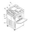
図1は、本発明の盗難防止装置の一実施形態が搭載された、本発明の画像形成装置の一実施形態に相当する複合機の外観図である。 FIG. 1 is an external view of a multi-functional peripheral, which is equipped with an embodiment of an anti-theft device of the present invention and corresponds to an embodiment of an image forming apparatus of the present invention.
図1に示す複合機100は、プリンタ、コピー機、スキャナ、ファクシミリとしての機能を有している。 The multifunction peripheral 100 shown in FIG. 1 has functions as a printer, a copying machine, a scanner, and a facsimile.
複合機100は、外観上、本体部101の上部に読取部102が載った構造を有する。読取部102は原稿の画像を読み取るものである。 The
また、複合機100の上部の正面側に操作部103および表示部104が配備されていて、複合機100の利用者はこの操作部103を、複合機100の正面側に立って操作する。 Further, the
操作部103は、利用者が複合機100に動作などを指示するために操作するものであり、表示部104は、複合機100の動作状態や複合機100に対する操作内容などを表示するものである。 The
本体部101の正面側には、開閉カバー101aと用紙トレイ101bが備えられており、開閉カバー101aは、トナーカートリッジなどの交換時や紙詰まりなどの際に利用者によって開かれる。用紙トレイ101bは、用紙の補充時などに利用者によって本体部101から引き出される。 An opening /
複合機100には、本発明の盗難防止装置の一実施形態が搭載されており、盗難者を特定する画像を撮影で得るため、複合機100には撮影部(カメラ)105も備えられている。 An embodiment of the antitheft device of the present invention is installed in the
図2は、図1に示す複合機100のハードウェア構成を概念的に示した構成図である。 FIG. 2 is a block diagram conceptually showing the hardware structure of the multifunction peripheral 100 shown in FIG.
複合機100には、図1にも示した読取部102、操作部103、表示部104、撮影部105、が備えられているとともに、上述した本体部101内には、画像形成部106、制御部107、通信部108も備えられている。 The multifunction peripheral 100 includes the
画像形成部106は、例えば電子写真方式などで用紙上に画像を形成するものであり、本発明にいう画像形成部の一例に相当する。この画像形成部106の詳細は後で説明する。 The
通信部108は、パーソナルコンピュータなどの外部機器からプリント用の画像データ等を得る機能や、複合機100の管理者に対して複合機100の内部状態などを送信する機能などを担うものである。 The
制御部107は、複合機100全体の動作制御を担うものであって、例えばCPUなどの演算素子やROMなどの記憶手段やタイマなどを備えたいわゆるボードコンピュータである。なお、近年では、MCU(Micro Controller Unit)として複合機100内の各所に制御機能が分散配備されていることも多いが、説明の便宜上、ここでは1つの制御部107に制御機能が集中しているものとする。 The
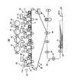
図3は、画像形成部106の構成例を示す図である。 FIG. 3 is a diagram illustrating a configuration example of the
図1に示す画像形成部106は、YMCKの各色に対応した4つの画像エンジン10が並列的に配置されたタンデム型の電子写真装置であり、単色の画像をプリントすることができるほか、4色のトナー像からなるフルカラーの画像をプリントすることができる。 The
各画像エンジン10は、感光体ドラム11、帯電装置12、露光装置13、現像装置14、一次転写装置15、および感光体クリーナ16を備えている。画像エンジン10が備えた各要素のうち、感光体ドラム11、帯電装置12、現像装置14、および感光体クリーナ16は、画像形成部106に対し着脱自在に装着されたドラムカートリッジ17に一体化されている。このドラムカートリッジ17は、図1に示された開閉カバー101aを開いた開口から画像形成部106に対して着脱される。画像形成部106には、開閉カバー101aの開閉を検知するカバースイッチ21が設けられている。このカバースイッチ21はメカニカルスイッチであり、図2に示す制御部107は、このカバースイッチ21の状態を確認することで開閉カバー101aの開閉状態を確認する。 Each
画像エンジン10の感光体ドラム11は表面に感光体層が設けられたドラムであり、表面に形成される像を保持して矢印A方向に回転する。帯電装置12、露光装置13、現像装置14、一次転写装置15、および感光体クリーナ16は、感光体ドラム11の周囲に矢印Aの方向の順に配置されている。 The photoconductor drum 11 of the
帯電装置12は、感光体ドラム11の表面を帯電させる装置である。露光装置13は、画像信号に応じた光を感光体ドラム11に照射することで、感光体ドラム11の表面に静電的な潜像を形成する。現像装置14は、トナーを含んだ現像剤を用いて感光体ドラム11の表面を現像する。一次転写装置15は、感光体ドラム11上のトナー像を中間転写ベルト31に転写する。感光体クリーナ16は、感光体ドラム11の表面を清掃する。 The charging
画像形成部106には、各画像エンジン10に対応した複数(ここでは4つ)のトナーカートリッジ18が画像形成部106に対し着脱自在に装着されており、各トナーカートリッジ18にはYMCK各色のトナーが収容されている。現像装置14には対応するトナーカートリッジ18からトナーが供給される。このトナーカートリッジ18も、図1に示された開閉カバー101aを開いた開口から画像形成部106に対して着脱される。 In the
上述したドラムカートリッジ17は、使用に伴って感光体ドラム11の劣化などが生じると交換されるものであり、本発明にいう消耗品の一例に相当する。また、画像形成部106内のドラムカートリッジ17が装着されている箇所は、本発明にいう消耗品搭載部の一例に相当する。 The above-mentioned drum cartridge 17 is replaced when the photosensitive drum 11 deteriorates due to use, and corresponds to an example of a consumable item according to the present invention. Further, the portion of the
ドラムカートリッジ17には、感光体ドラム11の使用時間などを含んだドラム情報が記録されたメモリ17aが備えられており、このメモリ17aと無線で通信してドラム情報の読み書きを行うドラム情報通信器22が画像形成部106に備えられている。図2に示す制御部107は、このドラム情報通信器22を介して、ドラムカートリッジ17に対するドラム情報の読み書きを行うとともにドラムカートリッジ17の抜き取りも検知する。 The drum cartridge 17 is provided with a
トナーカートリッジ18は、使用に伴ってトナーが消耗されると交換されるものであり、本発明にいう消耗品の一例に相当する。また、画像形成部106内のトナーカートリッジ18が装着されている箇所は、本発明にいう消耗品搭載部の一例に相当する。 The
トナーカートリッジ18には、トナーの残量などを含んだトナー情報が記録されたメモリ18aが備えられており、このメモリ18aと無線で通信してトナー情報の読み書きを行うトナー情報通信器23が画像形成部106に備えられている。図2に示す制御部107は、このトナー情報通信器23を介して、トナーカートリッジ18に対するトナー情報の読み書きを行うとともにトナーカートリッジ18の抜き取りも検知する。 The
画像形成部106には、転写ユニット30、二次転写装置40、定着装置50、用紙搬送部60も備えられている。転写ユニット30は中間転写ベルト31を備え、中間転写ベルト31は、画像形成部10および二次転写装置40を経由して矢印Bの方向に循環移動する。中間転写ベルト31には各画像エンジン10からトナー像が転写され、中間転写ベルト31はそのトナー像を保持して二次転写装置40へと搬送する。 The
用紙搬送部60は、用紙トレイ101bに収容された用紙Pを取り出して搬送ロール61で、二次転写装置40および定着装置50を経由させて搬送するものである。 The
二次転写装置40では、中間転写ベルト31上のトナー画像と用紙Pが重なり、電圧の印加によってトナー画像が用紙Pに転写される。 In the
定着装置50は、トナー像を加熱し加圧して用紙P上に定着させる。 The fixing
用紙トレイ101bに収容された用紙Pは、本発明にいう記録材の一例に相当するとともに、画像形成部106の稼働に伴い消耗されるので、本発明にいう消耗品の一例にも相当する。画像形成部10には、用紙トレイ101bに収容された用紙Pの残量を検知する用紙残量検知器24と、用紙トレイ101bの引出しを検知するトレイスイッチ25を備えている。用紙残量検知器24は、用紙トレイ101b内の用紙Pを、用紙搬送部60が取り出せる高さまで持ち上げる時の高さによって残量を検知するものであり、トレイスイッチ25はメカニカルスイッチである。図2に示す制御部107は、用紙残量検知器24によって検知された残量を取得するとともに、トレイスイッチ25の状態を確認することによって用紙トレイ101bの引出しも検知する。用紙残量検知器24は、本発明にいう取出検知器の一例に相当する。 The paper P stored in the
次に、図1および図2に示す複合機100に組み込まれた盗難防止装置の機能について説明する。 Next, the function of the anti-theft device incorporated in the multifunction peripheral 100 shown in FIGS. 1 and 2 will be described.
図4は、本発明の盗難防止装置の一実施形態としての機能構成を示す機能ブロック図である。 FIG. 4 is a functional block diagram showing a functional configuration as one embodiment of the anti-theft device of the present invention.
機能としての盗難防止装置200は、撮影部201、分析部202、記憶部203、取出検知部204、メール発行部205、表示部206を備えている。盗難防止装置200における撮影部201および表示部206は、ハードウェアとしては、図1および図2に示す撮影部105および表示部104がそれぞれ担っている。また、盗難防止装置200における分析部202および記憶部203は、ハードウェアとしては、図2に示す制御部107が担っている。更に、盗難防止装置200における取出検知部204は、ハードウェアとしては、図2に示す制御部107と、図3で説明したドラム情報通信器22や用紙残量検知器24との組み合わせが担っている。更にまた、盗難防止装置200におけるメール発行部205は、ハードウェアとしては、図2に示す制御部107と通信部108との組み合わせが担っている。 The
撮影部201は、撮影範囲である複合機100周辺の画像を常時撮影するものである。この撮影により、複合機100の利用者については、複合機100に接近中の様子を示す画像や接近後の顔の画像などが得られる。この撮影部201が、本発明にいう画像取得部の一例に相当する。 The
分析部202は、撮影部201による撮影で得られた画像を分析して人物や顔等を検出するものである。分析方法については、従来知られた任意の分析方法が採用され得るので、ここでは詳細説明は省略するが、複合機100に対する人物の接近と、複合機100周辺に到達後の滞在は区別されて検知されるものとする。この分析部202が、本発明にいう接近検知器の一例に相当する。 The
持ち去り検知部204は、図3で説明したドラム情報通信器22や用紙残量検知器24などを介して消耗品の持ち去りを検知し、検知時刻などを含んだ検知情報を生成するものである。また、持ち去り検出部204は、持ち去りの検知に関連して、図3で説明したカバースイッチ21やトレイスイッチ25を介した開閉確認なども行う。この持ち去り検知部204が、本発明にいう持ち去り検知器の一例に相当する。 The carry-out
記憶部203は、撮影部201による撮影で得られた画像を一時的に記憶する機能と、その画像を、持ち去り検知部204で生成された検知情報とともに保存する機能とを有するものである。また、本実施形態では、記憶部203は、上述したドラム情報やトナー情報も記憶し、更に、用紙トレイ101bにおける用紙の残量も記憶する。この記憶部203が、本発明にいう記録部の一例に相当する。なお、記憶部203は、いわゆる不揮発性の記憶手段を有しており、複合機100の電源が切られた場合であっても記憶内容を保持している。 The
メール発行部205は、記憶部203に検知情報が記憶される度に、その検知情報と画像を複合機100の管理者に宛てて送る電子メールを作成して送信する。 Every time the detection information is stored in the
表示部206は、記憶部203に記憶された検知情報の一覧を、管理者が複合機100にアクセスした場合に、管理者の指示を待たずに警告表示する。また、一覧に記載された検知情報に対応付けられている画像については、管理者の指示に応じて表示する。 The
メール発行部205は、本発明にいう報知部の一例に相当し、表示部206は、本発明にいう報知部の他の一例に相当する。 The
以下、盗難防止装置200の動作についてフローチャートを参照しながら説明する。また、フローチャートの説明に際して図1〜4も、特に図番を断らず符号を示して参照するものとする。 The operation of the
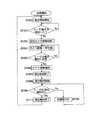
図5は、複合機100の通常の処理中における盗難防止装置200の動作手順を示すフローチャートである。 FIG. 5 is a flowchart showing an operation procedure of the
図5のフローチャートが示す通常処理の動作は、後述する電源オン時の処理動作が終了すると開始される。 The operation of the normal processing shown by the flowchart of FIG. 5 is started when the processing operation at the time of power-on, which will be described later, is completed.
この通常処理の動作が開始されると、撮影部201および分析部202により、複合機100に対する人物(利用者)の接近検知が開始され(ステップS101)、接近が検知されるまで待機状態となる(ステップS102;N)。 When the operation of this normal process is started, the
複合機100に対する利用者の接近が検知された場合(ステップS102;Y)は、前回の撮影で得られて一時的に記憶部203に記憶されていた画像が削除され(ステップS103)、今回の撮影で得られた画像が一時的に記憶部203に記憶される(ステップS104)。利用者の撮影と画像の記憶は、利用者が複合機100の前に到着するまで継続される(ステップS105;N)。 When the user's approach to the multifunction peripheral 100 is detected (step S102; Y), the image obtained by the previous shooting and temporarily stored in the
利用者が複合機100の前に到着すると(ステップS105;Y)、一時的に記憶部203に記憶されている画像の中から、利用者の顔が大きく明確に判別される画像が選択される(ステップS106)。そして、接近検知が終了され(ステップS107)、複合機100周辺における利用者の滞在検知が開始される(ステップS108)。 When the user arrives in front of the multi-function peripheral 100 (step S105; Y), an image in which the user's face is large and clearly discriminated is selected from the images temporarily stored in the
その後、複合機100周辺に利用者が滞在している間(ステップS109;N)は、複合機100は利用者が指示したコピー処理やプリント処理などを受け付けて実行する(ステップS110)。このとき、画像形成部106の稼働に伴って用紙やトナーが消費され、感光体ドラムの劣化も徐々に進む。このため、記憶部203に記憶されているドラム情報やトナー情報や用紙の残量が適宜に更新される。また、ステップS110で受け付けられる処理としては、複合機100の電源を切る処理も含まれ、電源を切る処理が実行された場合には、図5に示すフローチャートの流れにかかわらず、通常処理の動作が終了する。 After that, while the user stays around the multifunction peripheral 100 (step S109; N), the multifunction peripheral 100 accepts and executes the copy process and the print process instructed by the user (step S110). At this time, paper and toner are consumed as the
上記ステップS109で、複合機100周辺における利用者の滞在が検知できなくなった場合(ステップS109;Y)は、利用者の滞在検知が終了し(ステップS111)、上記ステップS101に動作が戻って、上述した各ステップが繰り返される。 If the user's stay in the vicinity of the multifunction peripheral 100 cannot be detected in step S109 (step S109; Y), the user's stay detection ends (step S111), and the operation returns to step S101. The steps described above are repeated.
次に、利用者が複合機100の消耗品を交換するときに盗難防止装置200が実行する消耗品交換処理について説明する。 Next, a consumable item replacement process executed by the
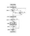
図6は、消耗品交換処理における盗難防止装置の動作手順を示すフローチャートである。 FIG. 6 is a flowchart showing the operation procedure of the anti-theft device in the consumable item replacement process.
この消耗品交換処理の動作は、開閉カバー101aの開放と用紙トレイ101bの引出しのいずれかが検知されると開始される。また、この消耗品交換処理の動作が開始される際には、図5のステップS108で開始された利用者の滞在検知が継続中であるものとする。 The operation of the consumable item replacement process is started when either opening of the opening /
消耗品交換処理が開始されると、開閉カバー101aの開放や用紙トレイ101bの引出しが検知される前に記憶部203に記憶されていたドラム情報やトナー情報や用紙の残量が「交換前残量」として取出検知部204に読み出される(ステップS201)。その後、消耗品の交換や補充が完了したことを表す開閉カバー101aの閉鎖や用紙トレイ101bの押し戻しが検知されず(ステップS202;No)、利用者も滞在中である(ステップS203;No)間は、待機状態となる。 When the consumables replacement process is started, the drum information, the toner information, and the remaining amount of the paper stored in the
消耗品の交換や補充の完了を表す開閉カバー101aの閉鎖や用紙トレイ101bの押し戻しが検知されたか(ステップS202;Yes)、利用者の滞在終了が検知された(ステップS203;Yes)場合には、取出検知部204は「交換後残量」として、ドラム情報通信器22およびトナー情報通信器23を介して現在のドラム情報およびトナー情報を取得し、用紙残量検知器24によって検知された現在の残量を取得する(ステップS204)。 When the closing of the open /
取出検知部204は、「交換前残量」に対して「交換後残量」が、予め決められた閾値以上に減少している場合や、ドラム情報通信器22およびトナー情報通信器23の少なくとも一方がトナーカートリッジ18およびドラムカートリッジ17の少なくとも一方について抜き取られたままであることを検知している場合には、消耗品の持ち去りが生じたと判定する(ステップS205;Yes)。 The
そして、取出検知部204は、記憶部203に一時的に記憶されている最新の人物画像と、現在時刻と、持ち去りが生じた消耗品の種別と、「交換前残量」および「交換後残量」と、を対応付けて記憶部203に保存記録として記憶させる(ステップS206)。ここで、現在時刻と消耗品種別と「交換前残量」と「交換後残量」とを併せたものが上述した検出情報である。この検出情報と対応付けられた人物画像は、人物(利用者)が複合機100に接近してきたときに撮影された画像であるため、人物を特定するために有効な顔などがよく写っていることが期待でき、消耗品の取り出しに連動した撮影に較べて盗難者の特定が確実である。 Then, the
このように、人物画像と検出情報が対応付けられて記憶部203に記録されると、その検出情報と人物画像とを含んだ電子メールがメール発行部205によって生成されて管理者宛に送信される(ステップS207)。このような電子メールは、消耗品の持ち出しが生じた場合に直ちに発行されるので即時性に優れている。 In this way, when the person image and the detection information are associated and recorded in the
電子メールの送信後は、記憶部203に記憶されていたドラム情報やトナー情報や用紙の残量が現在の情報や残量に更新されて(ステップS208)消耗品交換処理が終了する。 After sending the e-mail, the drum information, the toner information, and the remaining amount of the paper stored in the
なお、ステップS205で、持ち去りが無いと判定された場合(ステップS205;No)は、人物画像や検出情報の記録は行われず、ドラム情報やトナー情報や用紙の残量が更新されて(ステップS208)消耗品交換処理が終了する。 If it is determined in step S205 that there is no carry-out (step S205; No), the person image and the detection information are not recorded, and the drum information, the toner information, and the remaining amount of paper are updated (step S205). S208) The consumable item replacement process ends.
なお、一旦はステップS205で持ち去りが生じたと判断された場合であっても、一定時間内に残量などが復帰した場合には、単に、交換品や補充品を取りに行っただけとも考えられるので、記憶部203の保存記録から削除してもよく、あるいは重要度が低いことを表した情報を付与してもよい。また、消耗品が持ち去られた量や価格などに応じた重要度を表した情報を保存記録に付与してもよい。 Even if it is determined in step S205 that the product has been taken away, if the remaining amount or the like is restored within a certain period of time, it may be considered that a replacement product or a replacement product is simply taken. Therefore, the information may be deleted from the storage record of the
次に、複合機100の電源投入に際して実行される電源オン処理について説明する。 Next, a power-on process executed when the power of the multifunction peripheral 100 is turned on will be described.
図7は、電源オン処理における盗難防止装置の動作手順を示すフローチャートである。 FIG. 7 is a flowchart showing the operation procedure of the anti-theft device in the power-on process.
電源オン処理は、複合機100の電源が投入されると開始され、まず、記憶部203に記憶されているドラム情報やトナー情報や用紙の残量が「交換前残量」として取出検知部204に読み出される(ステップS301)。次に、取出検知部204は「交換後残量」として、ドラム情報通信器22およびトナー情報通信器23を介して現在のドラム情報およびトナー情報を取得し、用紙残量検知器24によって検知された現在の残量を取得する(ステップS302)。 The power-on process is started when the power of the multifunction peripheral 100 is turned on. First, the drum information and the toner information stored in the
取出検知部204は、「交換前残量」に対して「交換後残量」が、予め決められた閾値以上に減少している場合や、ドラム情報通信器22およびトナー情報通信器23の少なくとも一方がトナーカートリッジ18およびドラムカートリッジ17の少なくとも一方について抜き取られたままであることを検知している場合には、電源の切断中に消耗品の持ち去りが生じたと判定する(ステップS303;Yes)。 The
そして、取出検知部204は、記憶部203に一時的に記憶されている最新の人物画像と上述した検出情報とを対応付けて記憶部203に保存記録として記憶させる(ステップS304)。このときの人物画像は、複合機100の電源を切った利用者の画像であり、この人物画像に写っている人物(利用者)は、消耗品を持ち出した盗難者である可能性が高い。このような人物画像は、消耗品の取り出しに連動した撮影では得られない人物画像であり、盗難者の特定が確実である。 Then, the
このように、人物画像と検出情報が対応付けられて記憶部203に記録されると、その検出情報と人物画像とを含んだ電子メールがメール発行部205によって生成されて管理者宛に送信され(ステップS305)、電源オン処理が終了する。 In this way, when the person image and the detection information are associated and recorded in the
なお、ステップS304で、持ち去りが無いと判定された場合(ステップS304;No)は、そのまま電源オン処理が終了する。 When it is determined in step S304 that there is no carry-out (step S304; No), the power-on process ends as it is.
以上説明したように、本発明の盗難防止装置によれば、消耗品の取り出しに連動して撮影される場合に較べて盗難者が確実に特定される。 As described above, according to the antitheft device of the present invention, the thief can be identified more reliably than in the case where the image is taken in conjunction with the removal of the consumable item.
なお、上記実施形態では、1つの撮影部(カメラ)で接近検知と人物撮影を行う例が示されているが、本発明にいう接近検知器と撮影機は、複数のカメラで分担される構成であってもよいし、接近検知器として焦電センサのようなカメラ以外の手段が用いられてもよい。 In the above-described embodiment, an example in which the approach detection and the person shooting are performed by one shooting unit (camera) is shown, but the approach detector and the shooting machine according to the present invention are shared by a plurality of cameras. Alternatively, means other than a camera such as a pyroelectric sensor may be used as the approach detector.
また、上記実施形態では、本発明にいう画像取得部の一例として、盗難防止装置に備えられた撮影部によって撮影画像を取得するものが示されているが、本発明にいう画像取得部は、盗難防止装置外に設けられた例えば監視カメラなどから画像を取得するものであってもよい。このような変形例の場合、人物の接近が本発明にいう接近検知器によって検知されると、この盗難防止装置が搭載された自装置の周辺などを撮影している監視カメラやネットワークカメラに対して画像取得部が接近時の画像を要求して取得する。そして、消耗品の持ち去りが検知された場合には、その取得した画像と持ち去り検知とが対応付けられて保存される。このような変形例では、自装置に搭載された撮影機によって画像を取得する場合に較べて自装置の周辺における撮影の死角が少ないことが期待され、接近者がより確実に撮影されると期待される。 Further, in the above embodiment, as an example of the image acquisition unit according to the present invention, the one that acquires a captured image by the imaging unit provided in the anti-theft device is shown, but the image acquisition unit according to the present invention is The image may be acquired from, for example, a surveillance camera provided outside the anti-theft device. In the case of such a modified example, when the approach of the person is detected by the approach detector according to the present invention, the surveillance camera or the network camera which takes a picture of the periphery of the self-apparatus equipped with the anti-theft device, etc. The image acquisition unit requests and acquires an image when approaching. Then, when the removal of the consumable item is detected, the acquired image and the removal detection are stored in association with each other. In such a modified example, it is expected that there will be less blind spots for photographing in the vicinity of the own device than in the case where an image is taken by a photographing device mounted in the own device, and it is expected that an approaching person will be more surely photographed. To be done.
また、上記実施形態では、本発明にいう報知部の一例として、電子メールによる報知と表示画面による報知を行うものが示されているが、本発明にいう報知部の報知方法は、電子メールによる即時性に優れた報知でも、検知情報を用紙上にプリントしたレポート出力による記録の保存性に優れた報知でも、画面表示による確認の容易性に優れた報知でもよい。また、本発明にいう報知部は必須ではなく、本発明の盗難防止装置は、管理者が記録にアクセスして検出情報や人物画像を取得する保安性に優れた形態であってもよい。 Further, in the above-described embodiment, as an example of the notifying unit according to the present invention, the one for notifying by e-mail and notifying by the display screen is shown. The notification may be excellent in immediacy, may be a notification in which the detection information is printed on a paper and is excellent in storage stability of records, or may be a notification in which confirmation by a screen display is easy. Further, the notification unit according to the present invention is not essential, and the antitheft device of the present invention may be in a form with excellent security such that the administrator accesses the record and acquires the detection information and the person image.
また、上記実施形態では、本発明の盗難防止装置が画像形成装置に組み込まれている例が示されているが、本発明の盗難防止装置は、画像形成装置以外の装置に組み込まれてもよい。 Further, in the above embodiment, an example in which the anti-theft device of the present invention is incorporated in the image forming apparatus is shown, but the anti-theft device of the present invention may be incorporated in a device other than the image forming device. .
また、上記実施形態では、複数の像保持体を備えたいわゆるタンデム方式を例として説明したが、本発明の画像形成装置は、1つの像保持体上に複数色のトナー像を形成するいわゆるリボルバ式の画像形成装置であってもよい。 Further, in the above-described embodiment, the so-called tandem system provided with a plurality of image carriers has been described as an example, but the image forming apparatus of the present invention is a so-called revolver that forms toner images of a plurality of colors on one image carrier. Type image forming apparatus may be used.
また、上記説明では画像形成装置の一例として複合機を示したが、本発明の画像形成装置はモノクロ専用機であってもよく、ファクシミリやコピー機やカラープリンタであってもよい。 Further, in the above description, a multi-function peripheral is shown as an example of the image forming apparatus, but the image forming apparatus of the present invention may be a monochrome dedicated machine, or may be a facsimile machine, a copying machine or a color printer.
また、上記説明では画像形成装置の一例として、中間転写ベルトを用いた間接転写方式の画像形成装置を示したが、本発明の画像形成装置は、画像形成部から用紙に直接トナー像が転写される直接転写方式の画像形成装置であってもよい。 Further, in the above description, an indirect transfer type image forming apparatus using an intermediate transfer belt is shown as an example of the image forming apparatus, but in the image forming apparatus of the present invention, the toner image is directly transferred from the image forming unit to the paper. The image forming apparatus may be a direct transfer type image forming apparatus.
100……複合機、101……本体部、102……読取部、103……操作部、104……表示部、105……撮影部(カメラ)、106……画像形成部、107……制御部、108……通信部、200……盗難防止装置、201……撮影部、202……分析部、203……記憶部、204……持ち去り検知部、205……メール発行部、206……表示部100 ... Composite machine, 101 ... Main body section, 102 ... Reading section, 103 ... Operation section, 104 ... Display section, 105 ... Shooting section (camera), 106 ... Image forming section, 107 ...
Claims (7)
Translated fromJapanese前記人物が撮影された画像を、前記接近検知器により該人物の接近が検知された場合に取得する画像取得部と、
前記消耗品の前記装置からの持ち去りを検知する取出検知器と、
前記取出検知器で前記持ち去りが検知された場合に、その検知前の最も近い時間に前記画像取得部で取得された画像を、その検知の情報と対応付けて記録する記録部と、
を備えたことを特徴とする情報処理装置。An approach detector that is provided in a device equipped with consumables and detects the approach of a person to the device,
An image acquisition unit that acquires an image of the person, when the approach detector detects the approach of the person,
Anejection detector for detectingremoval of the consumable item from the device,
When the take-out detector is detected by the take-out detector, an image acquired by theimage acquisition unit at the closest time before the detection, a recording unit that records the information in association with the detection information,
Aninformation processing apparatus comprising:
前記取出検知器で前記持ち去りが検知された場合に、その検知前の時間に人物が撮影された画像を、その検知の情報と対応付けて記録する記録部と、 When the take-out detector is detected by the take-out detector, an image of a person photographed at a time before the detection, a recording unit that records the image in association with the detection information,
を備えたことを特徴とする情報処理装置。An information processing apparatus comprising:
前記人物が撮影された画像を、前記接近検知器により該人物の接近が検知された場合に取得する画像取得部と、を更に備え、
前記記録部は、前記画像取得部によって取得された画像を記録することを特徴とする請求項5に記載の情報処理装置。An approach detector for detecting the approach of a person to the device,
An image acquisition unit that acquires an image of the person captured when the approach detector detects the approach of the person,
The information processing apparatus according to claim 5, wherein the recording unit records the image acquired by the image acquisition unit .
Priority Applications (3)
| Application Number | Priority Date | Filing Date | Title |
|---|---|---|---|
| JP2016063084AJP6682948B2 (en) | 2016-03-28 | 2016-03-28 | Information processing device |
| US15/218,471US20170279976A1 (en) | 2016-03-28 | 2016-07-25 | Antitheft apparatus and image forming apparatus |
| CN201610796388.XACN107239025B (en) | 2016-03-28 | 2016-08-31 | Anti-theft equipment and image forming equipment |
Applications Claiming Priority (1)
| Application Number | Priority Date | Filing Date | Title |
|---|---|---|---|
| JP2016063084AJP6682948B2 (en) | 2016-03-28 | 2016-03-28 | Information processing device |
Publications (2)
| Publication Number | Publication Date |
|---|---|
| JP2017182107A JP2017182107A (en) | 2017-10-05 |
| JP6682948B2true JP6682948B2 (en) | 2020-04-15 |
Family
ID=59899095
Family Applications (1)
| Application Number | Title | Priority Date | Filing Date |
|---|---|---|---|
| JP2016063084AActiveJP6682948B2 (en) | 2016-03-28 | 2016-03-28 | Information processing device |
Country Status (3)
| Country | Link |
|---|---|
| US (1) | US20170279976A1 (en) |
| JP (1) | JP6682948B2 (en) |
| CN (1) | CN107239025B (en) |
Family Cites Families (9)
| Publication number | Priority date | Publication date | Assignee | Title |
|---|---|---|---|---|
| JP3726695B2 (en)* | 2001-04-03 | 2005-12-14 | オムロン株式会社 | Vehicle theft monitoring system, vehicle mounted device, vehicle abnormality monitoring method, vehicle theft monitoring method, vehicle theft monitoring program, and computer-readable recording medium recording the same |
| US6982810B2 (en)* | 2001-09-14 | 2006-01-03 | Hewlett-Packard Development Company, L.P. | Detecting theft of print substance from a printing device |
| JP2004080309A (en)* | 2002-08-15 | 2004-03-11 | Fuji Photo Film Co Ltd | Digital camera |
| JP3925395B2 (en)* | 2002-11-07 | 2007-06-06 | 株式会社デンソー | Vehicle antitheft device and vehicle antitheft system |
| JP2005142991A (en)* | 2003-11-10 | 2005-06-02 | Murata Mach Ltd | Color copy composite machine |
| JP2009122946A (en)* | 2007-11-14 | 2009-06-04 | Fujitsu Ten Ltd | Information storage device |
| JP2011232519A (en)* | 2010-04-27 | 2011-11-17 | Brother Ind Ltd | Image processing device |
| CN202771446U (en)* | 2012-07-23 | 2013-03-06 | 高育新 | Face image acquisition and recognition apparatus |
| JP6289154B2 (en)* | 2014-02-18 | 2018-03-07 | キヤノン株式会社 | System having information processing apparatus and network camera, information processing apparatus and login method thereof |
- 2016
- 2016-03-28JPJP2016063084Apatent/JP6682948B2/enactiveActive
- 2016-07-25USUS15/218,471patent/US20170279976A1/ennot_activeAbandoned
- 2016-08-31CNCN201610796388.XApatent/CN107239025B/enactiveActive
Also Published As
| Publication number | Publication date |
|---|---|
| CN107239025B (en) | 2021-05-11 |
| US20170279976A1 (en) | 2017-09-28 |
| CN107239025A (en) | 2017-10-10 |
| JP2017182107A (en) | 2017-10-05 |
Similar Documents
| Publication | Publication Date | Title |
|---|---|---|
| JP6208516B2 (en) | Image forming apparatus, image forming apparatus control method, program, and recording medium | |
| CN111050012B (en) | Image forming apparatus, storage medium, and control method | |
| JP2009143141A (en) | Image forming apparatus | |
| US7808662B2 (en) | Removing print job from printing queue for image-forming device and temporarily holding print job | |
| JP6444022B2 (en) | Image forming apparatus, image forming apparatus control method, program, and recording medium | |
| JP6396235B2 (en) | Image forming apparatus | |
| JP2008199386A (en) | Image forming apparatus, image forming method, and image forming program | |
| JP6682948B2 (en) | Information processing device | |
| JP6503422B2 (en) | Image forming apparatus, control method of image forming apparatus, program, and recording medium | |
| JP4906748B2 (en) | Image forming apparatus | |
| US11561487B2 (en) | Image forming apparatus for regulating removal of developer storage portion, regulation method | |
| JP6361521B2 (en) | Image forming apparatus | |
| JP2004054112A (en) | Image processing apparatus, method for ordering consumables for image processing apparatus, storage medium, and program | |
| JP5790111B2 (en) | Image forming apparatus, control method, and control program | |
| JP2009222892A (en) | Image forming apparatus and life determination method of imaging unit in the image forming apparatus | |
| JP2023035386A (en) | Image forming device, control method therefor and computer program | |
| JP2006086693A (en) | Image reading apparatus and image reading method | |
| JP5401515B2 (en) | Image forming apparatus | |
| JP7005253B2 (en) | Image forming device | |
| JP6780613B2 (en) | Image forming device and image forming system | |
| JP6121318B2 (en) | Image forming apparatus | |
| JP2009078411A (en) | Image forming apparatus and its management system | |
| JP2019032533A (en) | Image forming apparatus | |
| JP2005017590A (en) | Image forming unit and image forming apparatus using it | |
| JP2005091905A (en) | Image forming apparatus, process cartridge, and double-sided printing control method |
Legal Events
| Date | Code | Title | Description |
|---|---|---|---|
| A621 | Written request for application examination | Free format text:JAPANESE INTERMEDIATE CODE: A621 Effective date:20190228 | |
| A131 | Notification of reasons for refusal | Free format text:JAPANESE INTERMEDIATE CODE: A131 Effective date:20191105 | |
| A521 | Written amendment | Free format text:JAPANESE INTERMEDIATE CODE: A523 Effective date:20191224 | |
| TRDD | Decision of grant or rejection written | ||
| A01 | Written decision to grant a patent or to grant a registration (utility model) | Free format text:JAPANESE INTERMEDIATE CODE: A01 Effective date:20200225 | |
| A61 | First payment of annual fees (during grant procedure) | Free format text:JAPANESE INTERMEDIATE CODE: A61 Effective date:20200309 | |
| R150 | Certificate of patent or registration of utility model | Ref document number:6682948 Country of ref document:JP Free format text:JAPANESE INTERMEDIATE CODE: R150 | |
| S533 | Written request for registration of change of name | Free format text:JAPANESE INTERMEDIATE CODE: R313533 | |
| R350 | Written notification of registration of transfer | Free format text:JAPANESE INTERMEDIATE CODE: R350 |