JP6682627B2 - Electrocautery hemostatic clip - Google Patents
Electrocautery hemostatic clipDownload PDFInfo
- Publication number
- JP6682627B2 JP6682627B2JP2018521593AJP2018521593AJP6682627B2JP 6682627 B2JP6682627 B2JP 6682627B2JP 2018521593 AJP2018521593 AJP 2018521593AJP 2018521593 AJP2018521593 AJP 2018521593AJP 6682627 B2JP6682627 B2JP 6682627B2
- Authority
- JP
- Japan
- Prior art keywords
- clip
- clip arm
- pair
- arm
- proximal
- Prior art date
- Legal status (The legal status is an assumption and is not a legal conclusion. Google has not performed a legal analysis and makes no representation as to the accuracy of the status listed.)
- Active
Links
Images


Classifications
- A—HUMAN NECESSITIES
- A61—MEDICAL OR VETERINARY SCIENCE; HYGIENE
- A61B—DIAGNOSIS; SURGERY; IDENTIFICATION
- A61B18/00—Surgical instruments, devices or methods for transferring non-mechanical forms of energy to or from the body
- A61B18/04—Surgical instruments, devices or methods for transferring non-mechanical forms of energy to or from the body by heating
- A61B18/12—Surgical instruments, devices or methods for transferring non-mechanical forms of energy to or from the body by heating by passing a current through the tissue to be heated, e.g. high-frequency current
- A61B18/14—Probes or electrodes therefor
- A—HUMAN NECESSITIES
- A61—MEDICAL OR VETERINARY SCIENCE; HYGIENE
- A61B—DIAGNOSIS; SURGERY; IDENTIFICATION
- A61B18/00—Surgical instruments, devices or methods for transferring non-mechanical forms of energy to or from the body
- A61B18/04—Surgical instruments, devices or methods for transferring non-mechanical forms of energy to or from the body by heating
- A61B18/12—Surgical instruments, devices or methods for transferring non-mechanical forms of energy to or from the body by heating by passing a current through the tissue to be heated, e.g. high-frequency current
- A—HUMAN NECESSITIES
- A61—MEDICAL OR VETERINARY SCIENCE; HYGIENE
- A61B—DIAGNOSIS; SURGERY; IDENTIFICATION
- A61B17/00—Surgical instruments, devices or methods
- A61B17/12—Surgical instruments, devices or methods for ligaturing or otherwise compressing tubular parts of the body, e.g. blood vessels or umbilical cord
- A61B17/122—Clamps or clips, e.g. for the umbilical cord
- A61B17/1227—Spring clips
- A—HUMAN NECESSITIES
- A61—MEDICAL OR VETERINARY SCIENCE; HYGIENE
- A61B—DIAGNOSIS; SURGERY; IDENTIFICATION
- A61B17/00—Surgical instruments, devices or methods
- A61B17/12—Surgical instruments, devices or methods for ligaturing or otherwise compressing tubular parts of the body, e.g. blood vessels or umbilical cord
- A61B17/128—Surgical instruments, devices or methods for ligaturing or otherwise compressing tubular parts of the body, e.g. blood vessels or umbilical cord for applying or removing clamps or clips
- A61B17/1285—Surgical instruments, devices or methods for ligaturing or otherwise compressing tubular parts of the body, e.g. blood vessels or umbilical cord for applying or removing clamps or clips for minimally invasive surgery
- A—HUMAN NECESSITIES
- A61—MEDICAL OR VETERINARY SCIENCE; HYGIENE
- A61B—DIAGNOSIS; SURGERY; IDENTIFICATION
- A61B18/00—Surgical instruments, devices or methods for transferring non-mechanical forms of energy to or from the body
- A61B18/04—Surgical instruments, devices or methods for transferring non-mechanical forms of energy to or from the body by heating
- A61B18/12—Surgical instruments, devices or methods for transferring non-mechanical forms of energy to or from the body by heating by passing a current through the tissue to be heated, e.g. high-frequency current
- A61B18/1206—Generators therefor
- A—HUMAN NECESSITIES
- A61—MEDICAL OR VETERINARY SCIENCE; HYGIENE
- A61B—DIAGNOSIS; SURGERY; IDENTIFICATION
- A61B18/00—Surgical instruments, devices or methods for transferring non-mechanical forms of energy to or from the body
- A61B18/04—Surgical instruments, devices or methods for transferring non-mechanical forms of energy to or from the body by heating
- A61B18/12—Surgical instruments, devices or methods for transferring non-mechanical forms of energy to or from the body by heating by passing a current through the tissue to be heated, e.g. high-frequency current
- A61B18/14—Probes or electrodes therefor
- A61B18/1442—Probes having pivoting end effectors, e.g. forceps
- A61B18/1445—Probes having pivoting end effectors, e.g. forceps at the distal end of a shaft, e.g. forceps or scissors at the end of a rigid rod
- A61B18/1447—Probes having pivoting end effectors, e.g. forceps at the distal end of a shaft, e.g. forceps or scissors at the end of a rigid rod wherein sliding surfaces cause opening/closing of the end effectors
- A—HUMAN NECESSITIES
- A61—MEDICAL OR VETERINARY SCIENCE; HYGIENE
- A61B—DIAGNOSIS; SURGERY; IDENTIFICATION
- A61B18/00—Surgical instruments, devices or methods for transferring non-mechanical forms of energy to or from the body
- A61B18/04—Surgical instruments, devices or methods for transferring non-mechanical forms of energy to or from the body by heating
- A61B18/12—Surgical instruments, devices or methods for transferring non-mechanical forms of energy to or from the body by heating by passing a current through the tissue to be heated, e.g. high-frequency current
- A61B18/14—Probes or electrodes therefor
- A61B18/1492—Probes or electrodes therefor having a flexible, catheter-like structure, e.g. for heart ablation
- A—HUMAN NECESSITIES
- A61—MEDICAL OR VETERINARY SCIENCE; HYGIENE
- A61B—DIAGNOSIS; SURGERY; IDENTIFICATION
- A61B17/00—Surgical instruments, devices or methods
- A61B17/00234—Surgical instruments, devices or methods for minimally invasive surgery
- A61B2017/00292—Surgical instruments, devices or methods for minimally invasive surgery mounted on or guided by flexible, e.g. catheter-like, means
- A—HUMAN NECESSITIES
- A61—MEDICAL OR VETERINARY SCIENCE; HYGIENE
- A61B—DIAGNOSIS; SURGERY; IDENTIFICATION
- A61B18/00—Surgical instruments, devices or methods for transferring non-mechanical forms of energy to or from the body
- A61B2018/00053—Mechanical features of the instrument of device
- A61B2018/00059—Material properties
- A61B2018/00071—Electrical conductivity
- A61B2018/00077—Electrical conductivity high, i.e. electrically conducting
- A—HUMAN NECESSITIES
- A61—MEDICAL OR VETERINARY SCIENCE; HYGIENE
- A61B—DIAGNOSIS; SURGERY; IDENTIFICATION
- A61B18/00—Surgical instruments, devices or methods for transferring non-mechanical forms of energy to or from the body
- A61B2018/00053—Mechanical features of the instrument of device
- A61B2018/00059—Material properties
- A61B2018/00071—Electrical conductivity
- A61B2018/00083—Electrical conductivity low, i.e. electrically insulating
- A—HUMAN NECESSITIES
- A61—MEDICAL OR VETERINARY SCIENCE; HYGIENE
- A61B—DIAGNOSIS; SURGERY; IDENTIFICATION
- A61B18/00—Surgical instruments, devices or methods for transferring non-mechanical forms of energy to or from the body
- A61B2018/00053—Mechanical features of the instrument of device
- A61B2018/00107—Coatings on the energy applicator
- A61B2018/00136—Coatings on the energy applicator with polymer
- A—HUMAN NECESSITIES
- A61—MEDICAL OR VETERINARY SCIENCE; HYGIENE
- A61B—DIAGNOSIS; SURGERY; IDENTIFICATION
- A61B18/00—Surgical instruments, devices or methods for transferring non-mechanical forms of energy to or from the body
- A61B2018/00315—Surgical instruments, devices or methods for transferring non-mechanical forms of energy to or from the body for treatment of particular body parts
- A61B2018/00482—Digestive system
- A61B2018/00494—Stomach, intestines or bowel
- A—HUMAN NECESSITIES
- A61—MEDICAL OR VETERINARY SCIENCE; HYGIENE
- A61B—DIAGNOSIS; SURGERY; IDENTIFICATION
- A61B18/00—Surgical instruments, devices or methods for transferring non-mechanical forms of energy to or from the body
- A61B2018/00571—Surgical instruments, devices or methods for transferring non-mechanical forms of energy to or from the body for achieving a particular surgical effect
- A61B2018/00589—Coagulation
- A—HUMAN NECESSITIES
- A61—MEDICAL OR VETERINARY SCIENCE; HYGIENE
- A61B—DIAGNOSIS; SURGERY; IDENTIFICATION
- A61B18/00—Surgical instruments, devices or methods for transferring non-mechanical forms of energy to or from the body
- A61B2018/00571—Surgical instruments, devices or methods for transferring non-mechanical forms of energy to or from the body for achieving a particular surgical effect
- A61B2018/00595—Cauterization
- A—HUMAN NECESSITIES
- A61—MEDICAL OR VETERINARY SCIENCE; HYGIENE
- A61B—DIAGNOSIS; SURGERY; IDENTIFICATION
- A61B18/00—Surgical instruments, devices or methods for transferring non-mechanical forms of energy to or from the body
- A61B2018/00982—Surgical instruments, devices or methods for transferring non-mechanical forms of energy to or from the body combined with or comprising means for visual or photographic inspections inside the body, e.g. endoscopes
- A—HUMAN NECESSITIES
- A61—MEDICAL OR VETERINARY SCIENCE; HYGIENE
- A61B—DIAGNOSIS; SURGERY; IDENTIFICATION
- A61B18/00—Surgical instruments, devices or methods for transferring non-mechanical forms of energy to or from the body
- A61B18/04—Surgical instruments, devices or methods for transferring non-mechanical forms of energy to or from the body by heating
- A61B18/12—Surgical instruments, devices or methods for transferring non-mechanical forms of energy to or from the body by heating by passing a current through the tissue to be heated, e.g. high-frequency current
- A61B18/14—Probes or electrodes therefor
- A61B2018/1405—Electrodes having a specific shape
- A61B2018/1412—Blade
- A61B2018/1415—Blade multiple blades
- A—HUMAN NECESSITIES
- A61—MEDICAL OR VETERINARY SCIENCE; HYGIENE
- A61B—DIAGNOSIS; SURGERY; IDENTIFICATION
- A61B18/00—Surgical instruments, devices or methods for transferring non-mechanical forms of energy to or from the body
- A61B18/04—Surgical instruments, devices or methods for transferring non-mechanical forms of energy to or from the body by heating
- A61B18/12—Surgical instruments, devices or methods for transferring non-mechanical forms of energy to or from the body by heating by passing a current through the tissue to be heated, e.g. high-frequency current
- A61B18/14—Probes or electrodes therefor
- A61B18/1442—Probes having pivoting end effectors, e.g. forceps
- A61B2018/1462—Tweezers
- A—HUMAN NECESSITIES
- A61—MEDICAL OR VETERINARY SCIENCE; HYGIENE
- A61B—DIAGNOSIS; SURGERY; IDENTIFICATION
- A61B18/00—Surgical instruments, devices or methods for transferring non-mechanical forms of energy to or from the body
- A61B18/04—Surgical instruments, devices or methods for transferring non-mechanical forms of energy to or from the body by heating
- A61B18/12—Surgical instruments, devices or methods for transferring non-mechanical forms of energy to or from the body by heating by passing a current through the tissue to be heated, e.g. high-frequency current
- A61B18/14—Probes or electrodes therefor
- A61B2018/1475—Electrodes retractable in or deployable from a housing
- A—HUMAN NECESSITIES
- A61—MEDICAL OR VETERINARY SCIENCE; HYGIENE
- A61B—DIAGNOSIS; SURGERY; IDENTIFICATION
- A61B18/00—Surgical instruments, devices or methods for transferring non-mechanical forms of energy to or from the body
- A61B18/04—Surgical instruments, devices or methods for transferring non-mechanical forms of energy to or from the body by heating
- A61B18/12—Surgical instruments, devices or methods for transferring non-mechanical forms of energy to or from the body by heating by passing a current through the tissue to be heated, e.g. high-frequency current
- A61B18/14—Probes or electrodes therefor
- A61B2018/1495—Electrodes being detachable from a support structure
- A—HUMAN NECESSITIES
- A61—MEDICAL OR VETERINARY SCIENCE; HYGIENE
- A61B—DIAGNOSIS; SURGERY; IDENTIFICATION
- A61B90/00—Instruments, implements or accessories specially adapted for surgery or diagnosis and not covered by any of the groups A61B1/00 - A61B50/00, e.g. for luxation treatment or for protecting wound edges
- A61B90/03—Automatic limiting or abutting means, e.g. for safety
- A61B2090/037—Automatic limiting or abutting means, e.g. for safety with a frangible part, e.g. by reduced diameter
Landscapes
- Health & Medical Sciences (AREA)
- Surgery (AREA)
- Life Sciences & Earth Sciences (AREA)
- Engineering & Computer Science (AREA)
- Biomedical Technology (AREA)
- Public Health (AREA)
- Nuclear Medicine, Radiotherapy & Molecular Imaging (AREA)
- Veterinary Medicine (AREA)
- General Health & Medical Sciences (AREA)
- Heart & Thoracic Surgery (AREA)
- Medical Informatics (AREA)
- Molecular Biology (AREA)
- Animal Behavior & Ethology (AREA)
- Physics & Mathematics (AREA)
- Otolaryngology (AREA)
- Plasma & Fusion (AREA)
- Reproductive Health (AREA)
- Vascular Medicine (AREA)
- Surgical Instruments (AREA)
Description
Translated fromJapanese本発明は、電気焼灼止血クリップに関する。 The present invention relates to an electrocautery hemostatic clip.
医師は、より積極的に介入的な治療上の内視鏡を用いた処置を進んで行う傾向が強くなってきており、それは、たとえば、より大きい病変(たとえば、癌性の塊)の除去、粘膜の下の組織を治療するために消化(GI)管の中の粘膜層の下での穿孔、組織の全層除去、GI管を通して装置を挿入し、次いで、GI管の外側の組織を治療するためにGI系の器官を突き通すこと、及び、手術後の諸問題(たとえば、手術後の漏出、外科的ステープル・ラインの破壊、吻合部漏出)の内視鏡による治療/修復を含む。これらの処置は、GI管の壁部を穿孔若しくは損傷させるリスクを増加させる可能性があり、又は、処置の一部として、GI管壁部の閉塞を必要とする可能性がある。内視鏡による閉塞は、コストを低減させ、これらの処置に関連する外傷及び不都合を低減させることが可能である。しかしながら、従来の組織閉塞装置は、特定の組織欠損を閉じるには不十分である可能性がある。 Physicians are becoming more willing to be more aggressive in interventional therapeutic endoscopic procedures, such as removal of larger lesions (eg, cancerous masses), Perforation under the mucosal layer in the digestive (GI) tract to treat tissue under the mucosa, full-thickness removal of tissue, inserting the device through the GI tract, then treating tissue outside the GI tract To penetrate an organ of the GI system to do so, and endoscopic treatment / repair of post-surgical problems (eg, post-surgical leakage, surgical staple line disruption, anastomotic leakage). These procedures may increase the risk of perforating or damaging the wall of the GI tract, or may require occlusion of the GI tract wall as part of the procedure. Endoscopic occlusions can reduce costs and reduce trauma and inconvenience associated with these procedures. However, conventional tissue occluding devices can be insufficient to close certain tissue defects.
本発明は、組織治療のための装置であって、近位端部から遠位端部へ長手方向に延びるとともに全長にわたって延びるチャネルを含み、かつ、装置の近位部に解放可能に連結されるカプセルと、近位端部が前記カプセルの前記チャネルの中に摺動可能に受け入れられるクリップ・アームと、を備える。前記クリップ・アームは、当該クリップ・アームの遠位端部が相互に離間するように前記カプセルの遠位端部を越えて遠位側に延出する開配置と、当該クリップ・アームの前記遠位端部が相互に引き寄せられるように前記カプセルの内面によって拘束される閉配置との間で移動可能である。前記クリップ・アームには、近位部と遠位部とを含むコア部材が連結され、前記近位部と前記遠位部とは、予め設定された荷重を受けた場合に、相互に分離するように相互に解放可能に連結される。前記コア部材には、導電性の制御部材が連結され、制御部材の近位端部は、電流を前記クリップ・アームに供給するために電源に接続される。 The present invention is a device for tissue treatment, comprising a channel extending longitudinally from the proximal end to the distal end and extending the entire length, and releasably coupled to the proximal portion of the device. A capsule and a clip arm having a proximal end slidably received within the channel of the capsule. The clip arm has an open configuration extending distally beyond the distal end of the capsule such that the distal ends of the clip arm are spaced apart from each other; It is moveable between a closed arrangement in which the proximal ends are constrained by the inner surface of the capsule so that they are drawn towards each other. A core member including a proximal portion and a distal portion is connected to the clip arm, and the proximal portion and the distal portion are separated from each other when subjected to a preset load. Are releasably connected to each other. An electrically conductive control member is coupled to the core member, and the proximal end of the control member is connected to a power source for supplying electrical current to the clip arm.
一実施態様において、前記装置の近位部は、可撓性部材と、前記可撓性部材の遠位端のブッシングとを含んでいてもよい。
一実施態様において、前記可撓性部材と前記ブッシングとは、当該可撓性部材を電流から保護するために非導電性要素によって相互に離間されていてもよい。In one embodiment, the proximal portion of the device may include a flexible member and a bushing at the distal end of the flexible member.
In one embodiment, the flexible member and the bushing may be separated from each other by a non-conductive element to protect the flexible member from electrical current.
一実施態様において、前記コア部材の前記近位部と前記遠位部とは、破壊可能なリンクによって相互に連結されていてもよい。
一実施態様において、前記カプセルは、絶縁されているか、又は非導電性材料から形成されているか、のいずれか一方であってもよい。In one embodiment, the proximal and distal portions of the core member may be interconnected by a breakable link.
In one embodiment, the capsule may be either insulated or formed of a non-conductive material.
一実施態様において、前記カプセルは、導電性材料から形成されていてもよい。
一実施態様において、前記制御部材の一部分は、前記装置の近位部を保護するために絶縁されていてもよい。In one embodiment, the capsule may be made of a conductive material.
In one embodiment, a portion of the control member may be insulated to protect the proximal portion of the device.
一実施態様において、電流が前記クリップ・アームの所望の部分に供給されるように当該クリップ・アームの一部分が絶縁されていてもよい。
一実施態様において、前記コア部材の前記近位部は、前記クリップ・アームの近位端部を嵌合するための拘束タブを含んでいてもよく、前記遠位部は、前記クリップ・アームのそれぞれを経由して横方向に延びる対応の切欠を嵌合させるための整合突出部を含んでいる。前記コア部材の前記遠位部は、解放可能に連結する何らかの手段を介して前記クリップ・アームに連結されていてもよく、解放可能に連結する何らかの手段は、たとえば、前記クリップ・アーム若しくは前記コア部材のいずれかの変形可能な部分、又は、前記クリップ・アーム若しくは前記コア部材のうちの1つに固定して連結される中間要素であり、そのそれぞれは、予め設定された荷重を受けた場合に、コア部材及びクリップ・アームの関係を断つように構成され得る。In one embodiment, a portion of the clip arm may be insulated so that current is supplied to the desired portion of the clip arm.
In one embodiment, the proximal portion of the core member may include a restraining tab for mating the proximal end of the clip arm, the distal portion of the clip arm Includes alignment protrusions for mating corresponding notches extending laterally therethrough. The distal portion of the core member may be connected to the clip arm via some means for releasable connection, such as any means for releasable connection may be, for example, the clip arm or the core. Any deformable part of the member or intermediate element fixedly connected to one of the clip arm or the core member, each of which when subjected to a preset load Can be configured to break the relationship between the core member and the clip arm.
一実施態様において、前記クリップ・アームの前記遠位端部は、当該クリップ・アームを介して電気エネルギーを受けた場合に把持した組織を焼灼するために、相互に向かって横方向に延びる鋭利な歯を含んでいてもよい。 In one embodiment, the distal ends of the clip arms are sharpened laterally toward one another to ablate the grasped tissue when receiving electrical energy through the clip arms. It may include teeth.
一実施態様において、前記クリップ・アームの内面は、電気エネルギーを受けた場合に組織を凝固させるように構成されていてもよい。
また、本発明は、近位部と遠位部とを備えたクリッピング装置に関する。前記近位部は、近位端部から遠位端部へ長手方向に延びる可撓性部材と、前記可撓性部材の遠位端部に連結されたブッシングとを含む。前記遠位部は、当該遠位部が近位部から配置可能になるように前記近位部に解放可能に連結されており、前記遠位部は、ブッシングに解放可能に連結されたカプセルを含んでおり、前記カプセルは、近位端部から遠位端部へ長手方向に延びるとともに全長にわたって延びるチャネルを含んでおり、近位端部から延びるクリップ・アームが前記カプセルの前記チャネルの中に摺動可能に受け入れられる。前記クリップ・アームは、当該クリップ・アームの遠位端部が前記カプセルの遠位端部を越えて遠位側に延びて相互に離間する開配置と、当該クリップ・アームが前記カプセルの内面によって拘束され、前記クリップ・アームの遠位端部が相互に引き寄せられる閉配置との間で移動可能である。前記クリップ・アームの前記近位端部には、コア部材が連結されており、前記コア部材は、予め設定された荷重を受けた場合に、機能しなくなるように設計された破壊可能なリンクによって相互に連結された近位部と遠位部とを含む。前記コア部材には、近位端部が電流を前記クリップ・アームに供給するために電源に接続された導電性の制御ワイヤが連結される。In one embodiment, the inner surface of the clip arm may be configured to coagulate tissue when subjected to electrical energy.
The present invention also relates to a clipping device having a proximal portion and a distal portion. The proximal portion includes a flexible member extending longitudinally from the proximal end to the distal end and a bushing coupled to the distal end of the flexible member. The distal portion is releasably coupled to the proximal portion such that the distal portion is deployable from the proximal portion, the distal portion including a capsule releasably coupled to a bushing. The capsule includes a channel extending longitudinally from the proximal end to the distal end and extending the entire length, with a clip arm extending from the proximal end in the channel of the capsule. Slidably received. The clip arm has an open configuration in which the distal end of the clip arm extends distally beyond the distal end of the capsule and is spaced apart from each other; and the clip arm is defined by an inner surface of the capsule. Restrained and moveable between a closed configuration in which the distal ends of the clip arms are drawn together. A core member is coupled to the proximal end of the clip arm by a breakable link designed to fail when subjected to a preset load. It includes a proximal portion and a distal portion interconnected. A conductive control wire is coupled to the core member, the proximal end of which is connected to a power source to supply current to the clip arm.
一実施態様において、前記クリッピング装置は、前記制御ワイヤの一部分に広がる絶縁シースをさらに含む。
一実施態様において、前記クリップ・アームの前記遠位端部は、相互に向かって横方向に延びる鋭利な歯を含む。In one embodiment, the clipping device further comprises an insulating sheath extending over a portion of the control wire.
In one embodiment, the distal ends of the clip arms include sharp teeth extending laterally toward each other.
一実施態様において、前記クリップ・アームの一部分は絶縁され得る。
また、本発明は、目標組織を治療するための方法であって、本方法は、カプセルと、遠位端部が相互に離間する開配置と遠位端部が相互に引き寄せ合う閉配置との間で移動可能に前記カプセルの中に摺動可能に収容されるクリップ・アームとを含み、クリッピング装置の近位部に解放可能に連結されるとともに当該近位部から配置可能な前記クリッピング装置の遠位部を、生体の中の目標領域まで挿入する工程と、前記クリップ・アームを目標組織に接触させて位置決めする工程と、目標組織を治療するために、カプセル及びクリップ・アームのうちの1つに接続された導電性部材を介して電気的なエネルギーをクリップ・アームに供給する工程と、を備える方法に関する。In one embodiment, a portion of the clip arm may be insulated.
The invention also provides a method for treating target tissue, the method comprising a capsule and an open configuration in which the distal ends are spaced apart from each other and a closed configuration in which the distal ends are drawn toward each other. A clip arm slidably received within the capsule so as to be movable therebetween, the clipping device releasably coupled to and deployable from a proximal portion of the clipping device. Inserting the distal portion into a target region in the body, positioning the clip arm in contact with the target tissue, and treating one of the capsule and the clip arm to treat the target tissue. Supplying electrical energy to the clip arm via a conductive member connected to one of the two.
一実施態様において、目標組織に接触させて前記クリップ・アームを位置決めする工程は、当該クリップ・アームの内面が目標組織に接触して設置され、目標組織を凝固させるように開配置に前記クリップ・アームを移動させる工程を含んでいてもよい。 In one embodiment, positioning the clip arm in contact with target tissue comprises placing the clip arm in an open configuration such that an inner surface of the clip arm is placed in contact with the target tissue and coagulates the target tissue. The step of moving the arm may be included.
一実施態様において、目標組織に接触して前記クリップ・アームを位置決めする工程は、当該クリップ・アームの遠位端部において鋭利な歯同士の間に目標組織を把持し、当該目標組織を焼灼する工程を含んでいてもよい。 In one embodiment, positioning the clip arm in contact with target tissue grasps the target tissue between sharp teeth at the distal end of the clip arm and cauterizes the target tissue. The process may be included.
一実施態様において、本方法は、開配置における前記クリップ・アームの当該遠位端部同士の間に組織の目標部分を位置決めし、前記組織の目標部分を把持するために閉配置に当該クリップ・アームを引き寄せることによって、前記組織の目標部分を挟持する工程をさらに備えていてもよい。 In one embodiment, the method positions a target portion of tissue between the distal ends of the clip arms in an open configuration and positions the clip portion in the closed configuration to grasp the target portion of the tissue. The method may further include the step of pinching the target portion of the tissue by pulling the arm.
一実施態様において、本方法は、クリップ・アームを閉配置でロックする工程、及び、装置の近位部から遠位部を配置する工程をさらに備えていてもよい。 In one embodiment, the method may further comprise locking the clip arms in a closed configuration and deploying the proximal to distal portions of the device.
本発明は、以下の説明及び添付の図面を参照してさらに理解され得、図面において、同様の要素は、同じ参照番号を用いて参照されている。本発明は、組織の穿孔、欠損、及び出血の少なくとも何れか1つを治療するための内視鏡クリッピング装置を対象とする。とりわけ、本発明の例示的な実施形態は、挟持能力及び凝固能力の両方を有する止血クリップを説明している。クリッピング装置の一部分は、所望の凝固効果を実現するために、絶縁されるか、又は、非導電性材料から形成されていてもよい。本明細書で使用される場合、「近位」及び「遠位」という用語は、装置のユーザに向かう方向(近位)、装置のユーザから離れる方向(遠位)を指すことを意図しているということに留意すべきである。 The present invention may be further understood with reference to the following description and the accompanying drawings, in which like elements are referenced with the same reference numerals. The present invention is directed to an endoscopic clipping device for treating at least one of tissue perforation, defect, and bleeding. Among other things, exemplary embodiments of the present invention describe a hemostatic clip having both pinching and coagulating capabilities. A portion of the clipping device may be either insulated or made of a non-conductive material to achieve the desired solidification effect. As used herein, the terms "proximal" and "distal" are intended to refer to a direction toward the user of the device (proximal), away from the user of the device (distal). It should be noted that
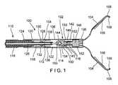
図1に示されているように、本発明の例示的な実施形態による装置100は、たとえば、内視鏡の動作経路を通して、治療対象の目標組織に向かって生体の中へ挿入可能な遠位部102を備える。装置は、身体を通る曲がりくねった経路を横断すること、たとえば、生体の開口を経由してアクセスされた生体の内腔を通して挿入される内視鏡の動作経路を通過することを許容する十分な可撓性を有する。遠位部102は、カプセル106の長手方向チャネル122の中に摺動可能に受け入れられた一対のクリップ・アーム104を含む。クリップ・アーム104は、当該クリップ・アーム104の遠位端部108が目標組織を受け入れるように相互に離間する開配置と、当該クリップ・アーム104の遠位端部108が目標組織を把持するために相互に向き合う閉配置との間で移動可能である。遠位部102は、装置100の近位部110に解放可能に連結されており、前記近位部110は、身体の外側に残留し、当該遠位部102が配置される際にユーザが操作可能なハンドル(図示せず)を含む。クリップ・アーム104は、カプセル106の中に延びる制御部材112によって、開配置と閉配置との間で移動可能である。制御部材112の近位端部は、ハンドルに設けたアクチュエータに連結される。本実施形態において、制御部材112の遠位端部114は、クリップ・アーム104の近位端部116に連結される。また、制御部材112の近位端部は、より詳細に下記に説明するように、目標組織にエネルギーを供給するために、制御部材112を介してクリップ・アーム104に電流を供給するエネルギー供給源に接続されていてもよい。 As shown in FIG. 1, a
装置100の近位部110は、カプセル106をハンドルに連結する可撓性部材118を含む。可撓性部材118は、生体の曲がりくねった経路さえも通って装置100の遠位部102を挿入することを容易にするために、たとえば、ワイヤのコイル、又は、何らかの別の適切な可撓性構造体として形成されていてもよい。カプセル106は、カプセル106に解放可能に連結されるブッシング120を介して可撓性部材118に連結されていてもよい。制御部材112は、クリップ・アーム104と連結されるように、可撓性部材118、ブッシング120、及びカプセル106を通って延びている。可撓性部材118とブッシング120とは、電気的に絶縁され、若しくは非導電性の材料から形成され、又は電気的に絶縁され、かつ、非導電性の材料から形成されて、ユーザ、周囲の器具、及び、目標とされていない組織が影響を受けないように保護する。絶縁体は、粉末コーティング若しくは収縮チュービングを使用して、又は、たとえば、プラスチック及び/若しくはセラミックなどのような、非導電性コンポーネントを使用することによって、生成し得る。絶縁材料は、アセタール(POM)、エポキシ、FEP、ポリイミド、PVDF、フェノール樹脂、PFA、ポリカーボネート、ポリスルホン、PVC、ポリフェニレンサルファイド、ポリエーテルイミド、シリコーン、ポリエーテルエーテルケトン(PEEK)、ポリテトラフルオロエチレン(PTFE)、及びポリエチレンを含んでいてもよい。絶縁体の厚さは、0.0005インチ(0.0127mm)から0.020インチ(0.508mm)の間にあることが可能であり、より具体的には、0.002インチ(0.0508mm)から0.006インチ(0.1524mm)の間にあることが可能である。 The
ブッシング120は、可撓性部材118の遠位端部126に取り付けられている近位端部124から、カプセル106に解放可能に連結されるブッシング遠位端部128へ長手方向に延びている。一実施形態において、ブッシング120は、カプセル106の対応する連結タブ132を受け入れるために、当該ブッシング120を横方向に連通する少なくとも1つの開口部130を含んでいてもよい。しかしながら、ブッシング120は、複数の開口部130を含んでいてもよく、特定の一実施形態においては、直径方向に互いに対向する一対の開口部130を含む。カプセル106及び可撓性部材118と同様に、ブッシング120は、周囲の領域がブッシング120を通る制御部材112を通る電流によって影響を受けることを防止するために、絶縁され、若しくは非導電性材料から形成され、又は、絶縁され、かつ、非導電性材料から形成されていてもよい。別の実施形態において、可撓性部材118及びブッシング120を通る予め設定された長さの制御部材112は、電流が制御部材112から装置100の周囲の部分へ流れることを防止するために、絶縁され、若しくはシース158によってカバーされ、又は、絶縁され、かつ、シース158によってカバーされていてもよい。制御部材112を囲繞する絶縁体及びシース158の少なくともいずれか一方は、クリッピング装置の周辺部に対して追加的な保護を提供し得る。しかしながら、本実施形態において、可撓性部材118及びブッシング120は、絶縁/非導電性であることは必要とされない。
カプセル106は、ブッシング120に形成された一対の開口部130に対応するいくつかの連結タブ132を含む。カプセル106は、近位端部134から遠位端部136へ長手方向に延びているとともに、当該カプセル106を長手方向に通って延びるチャネル122を含む。連結タブ132は、当該連結タブ132がブッシング120の開口部130のうちの対応するものの中に受け入れられる場合にカプセル106及びブッシング120が相互に連結されるように、近位端部134から半径方向内向きに延びている。カプセル106はまた、当該カプセル106の近位部に沿ってカプセル106を横方向に通る一対の窓138を含む。一対の窓138は、さらに詳細に下記に説明されるように、クリップ・アーム104の近位端部116に設けたロッキング部材140を受け入れる寸法、形状を有する。本装置100は、開口部130と連結タブ132とによってブッシング120とカプセル106とを連結するものとして示されているが、ブッシング120とカプセル106とが相互に解放可能に連結されており、本装置100の遠位部102の配置時に解放可能である限りにおいて、ブッシング120とカプセル106とは、さまざまな方式のいずれかによって相互に連結されてもよい。 The
本実施形態のクリップ・アーム104は、予め設定された荷重を受けた場合に、近位部144と遠位部146とが相互に分離するように、相互に解放可能に連結された近位部144と遠位部146とを含むコア部材142によって制御部材112に連結される。一実施形態において、解放可能な連結は、予め設定された荷重を受けた場合に、分離又は破壊するように設計された破壊可能なリンク148であってもよい。破壊可能なリンクは、連結が予め設定された荷重を受けるまでは適切な場所に残存し、前記荷重が作用した場合に機能しなくなる限りにおいて、溶接又は他の適切な連結として形成されてもよい。コア部材142は、制御部材112に流れた電流がコア部材142を通ってクリップ・アーム104に至るように、導電性の材料から形成されている。制御部材112の遠位端部114は、たとえば、近位部144に形成され、拡大された遠位端部114に対応する寸法、形状を有するキャビティ154の中に受け入れられる当該遠位端部114によって、近位部144に連結される。このように、制御部材112がカプセル106に対して相対的に長手方向に動かされた際、コア部材142、したがってクリップ・アーム104は、カプセル106に対して相対的に動かされる。 The
本実施形態の近位部144は、クリップ・アーム104の近位端部116を嵌合させるために、近位部144の両側に配置される一対のタブ150を含む。遠位部146は、クリップ・アーム104の一部分を通して横方向に延び、対応した寸法、形状が設定される切欠を嵌合させるためにそれぞれが対応するタブ150の1つに対して長手方向に整合する整合突出部152を含む。整合突出部152は、それぞれに対するクリップ・アーム104との整合を維持する。コア部材142は、破壊可能なリンク148によって相互に連結された部分を有する単一の要素として説明されて示されているが、クリップ・アーム104は、他のメカニズムによってそれぞれが連結するとともに整合していてもよい。たとえば、コア部材142は、当業者によって理解されるように、単一のものであってもよく、又は、分離可能なジョイントによるさまざまな方式で相互に連結される2つ以上の別々の要素から構成されてもよい。 The
クリップ・アーム104は、当該クリップ・アーム104がカプセル106の遠位端部136を超えて遠位側に動かされた際にクリップ・アーム104の遠位端部108が相互に開配置に離間するように、開配置に付勢されている。クリップ・アーム104がカプセル106内へ近位側に引き込まれた場合、当該クリップ・アーム104は、カプセル106の内面と接触することによって、閉配置に移動し、カプセル106によって閉じた位置に保持される。上述のように、クリップ・アーム104は、制御部材112によって開配置と閉配置との間で移動する。クリップ・アーム104は、制御部材112に流れた電流がクリップ・アーム104に流れて当該クリップ・アーム104と接触している目標組織に至るように、導電性の材料から形成されている。閉配置にクリップ・アーム104を引き寄せるために必要とされる引っ張り距離は、制御部材112の導電性部分、コア部材142、及びクリップ・アーム104が、可撓性部材118のいずれの導電性部分にも決して引き込まれないようなものとなるように、クリップ・アーム104とカプセル106とが構成されている。 The
クリップ・アーム104の小さい電流放出領域を備えた特徴部、たとえば、鋭利なエッジなどは、焼灼エッジ又は切除エッジとして使用され得る。たとえば、クリップ・アーム104の遠位端部108における鋭利な歯109は、相互に横方向に延びて、歯109、歯109の間に組織を把持した際に、当該鋭利な歯109に接触している組織を焼灼するために使用され得る。大きい電流放出領域を備えた特徴部、たとえば、滑らかな表面などは、凝固のために使用されてもよい。たとえば、クリップ・アーム104の長手沿いの内面156(すなわち、クリップ・アーム104が相互に引き寄せられている場合に相互に面するクリップ・アーム104の表面)は、組織に押圧されている場合に凝固効果をもたらすために使用されてもよい。別の例において、クリップ・アーム104は、遠位端部108の鋭利な歯109が相互に接合されて滑らかな遠位エッジを形成するように、閉配置に移動してもよい。この滑らかな遠位エッジは、より小さい領域の組織を凝固させるために使用され得る。さらに別の例において、クリップ・アーム104の遠位表面は、閉配置において、目標組織に押圧され、組織を凝固させることが可能である。クリップ・アーム104の異なる領域が組織に押圧された際に、当該組織に対して異なる効果をもたらし得る。しかして、先端部の幾何学形状及び材料構造は、組織に作用する電流密度を変化させ得る。大きい領域、たとえば、クリップ・アーム104の内面又は外面などは、凝固に関してより低い電流密度効果をもたらす。より小さく、より鋭利な領域、たとえば、クリップ・アーム104の先端部又は鋭利な歯109などは、切除に関してより高い電流密度効果をもたらす。例示的な実施形態は、完全に導電性のものとして、クリップ・アーム104のすべてを示して説明しているが、その所望の部分が導電性となるように、クリップ・アーム104の一部分を絶縁することも可能である。たとえば、クリップ・アーム104の遠位先端部だけが導電性であることが望まれ得る。 Features with a small current emitting area of the
上述のように、装置100は、目標領域を治療するために望まれるとき又は必要な場合には、目標組織の焼灼や切除、凝固、及び挟持の少なくとも何れか1つを行う。焼灼及び凝固効果は、制御部材112の近位端部に接続された電源の投入及び遮断によって制御され得る。組織を焼灼又は凝固することが望まれる場合には、電源は、電流がクリップ・アーム104に流れるように、投入され得る。所望の焼灼及び/又は凝固効果が実現された場合、又は、装置100の挟持機能を利用することが望まれる場合には、挟持された組織へのエネルギーのさらなる印加を施すことなくクリップ・アーム104が目標組織に位置決めされて当該目標組織を挟持するように、電源が遮断される。目標組織がクリップ・アーム104の間に位置決めされると、クリップ・アーム104は、より詳細に下記に説明されるように、装置100の遠位部102が目標組織に配置され得るように、閉配置に移動可能である。 As described above, the
例示的な方法によれば、装置100の遠位部102は、たとえば、内視鏡の動作経路を通して、生体の中の目標領域まで挿入され得る。遠位部102は、閉配置で動作経路を通して挿入され得る。しかしながら、遠位部102が目標領域に到達すると、制御部材112をカプセル106に対して遠位側に移動させることによって、クリップ・アーム104は、開配置へ移動可能である。クリップ・アーム104は、開配置と閉配置との間で移動可能なものであり、所望の効果を実現し得る仕方で、組織を把持するか、組織に接触するか、その両方を行う。たとえば、切除するために、クリップ・アーム104の遠位端部108は、開配置で、切除される組織の領域の周辺に位置決めされ得る。クリップ・アーム104は、切除が望まれる目標領域の部分がクリップ・アーム104の遠位端部108の鋭利なエッジ又は歯109同士の間に把持され得るように、閉配置に引き寄せられ得る。制御部材112を流れる電流がクリップ・アーム104に流れて遠位端部108に至り、把持されている組織を焼灼/切除するように、電源が投入され得る。また、目標領域の中の組織の一部分を凝固することが望まれる。一例において、クリップ・アーム104は、内面156が治療対象の組織に接触するように、開配置で治療対象の組織の一部分にわたって位置決めされてもよい。クリップ・アーム104は、組織との接触の面積を増加させるように、閉配置にわずかに移動してもよい。別の例において、閉配置にあるクリップ・アーム104は、組織を凝固させるための滑らかな遠位エッジを形成し得る。滑らかな遠位エッジは、より多くの組織の目標とされた部分を凝固させるために使用され得る。電源を投入することにより、電流がクリップ・アーム104に流れ、クリップ・アーム104が接触している組織を凝固させる。所望の焼灼や凝固効果が達成されるまで、上述の工程が繰り返され得る。 According to an exemplary method, the
所望の焼灼や凝固が完了した場合、又は、装置100の挟持態様を利用することが望まれる場合には、電源が遮断されるとともに、クリップ・アーム104が組織の挟持対象となる部分周辺に位置決めされ得る。組織の挟持対象となる部分がクリップ・アーム104の間に位置決めされると、クリップ・アーム104は、組織が当該クリップ・アーム104の間に把持されるように、閉配置に移動される。クリップ・アーム104は、組織の所望の部分が把持されるまで、開配置と閉配置との間で移動可能である。1つの特定の実施形態において、コア部材142の近位端部160が近位に移動し、カプセル106の連結タブ132に接触するまで、制御部材112をさらに近位に引き寄せることによって、装置100の遠位部102は、クリップ・アーム104が閉配置の状態で配置され得る。タブ132に対する近位方向の力は、ブッシング120の開口部130からタブ132を押し出し、ブッシング120からカプセル106を解放する。制御部材112のさらなる近位方向の運動は、クリップ・アーム104を閉配置でロックするべく窓138に嵌合させるために、クリップ・アーム104の近位端部116を解放するように、コア部材142との関係を解消する。コア部材142の近位部144は、カプセル106から外へ近位側に引き寄せられ、それによって、装置100の遠位部102を近位部から分離し、装置を体の中に配置する。 When the desired cauterization or coagulation is completed, or when it is desired to utilize the pinching aspect of the
上述の配置工程は、装置100の遠位部がどのように配置され得るかということの1つの例である。クリップ・アーム104を閉配置でロックしつつ、カプセル106をブッシング120から解放する配置である限りにおいて、遠位部102は、コア部材142の構成、及び/又はブッシング120とカプセル106との間の連結に応じて、さまざまな異なる方式で配置され得る。 The placement process described above is one example of how the distal portion of
代替的な実施形態によれば、図2に示されるように、装置100’は、上述の装置100と概ね同様であり、カプセル106’の中に摺動可能に受け入れられ、制御部材112’によって開配置と閉配置との間で移動されるクリップ・アーム104’を含む遠位部102’を備える。装置100’は、装置100と概ね同じ仕方で使用され得る。しかしながら、カプセル106’は、絶縁されていたり、非導電性材料から形成されていたりするのではなく、むしろ、電気的なエネルギーが流れ得るように導電性材料から形成されている。たとえば、電気的なエネルギーは、装置100に関連して概ね既述しているように、制御部材112’を通り、カプセル106’と接触するコア部材142’及びクリップ・アーム104’の少なくとも何れか一方によってカプセル106’に伝わり得る。 According to an alternative embodiment, as shown in FIG. 2, the device 100 'is generally similar to the
装置100と同様に、遠位部102’は、ブッシング120’によって、装置100’の近位部110’の可撓性部材118’に解放可能に連結される。しかしながら、近位部110’は、ブッシング120’と可撓性部材118’との間に位置決めされ、可撓性部材118’を電流からさらに保護する非導電性セパレータ162’をさらに含む。上述の装置100と概ね同様に、可撓性部材118’はまた、制御ワイヤ112’の内部に延びている制御ワイヤ112’の被覆部、及び非導電性シース158’を有する制御ワイヤ112’の被覆部の少なくとも何れか一方によって、電流から保護され得る。 Similar to
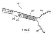
図3および図4に示されるように、別の例示的な実施形態による装置200は、上述の装置100と概ね同様であり、開配置と閉配置との間でカプセル206の中を摺動可能である一対のクリップ・アーム204を備える。しかしながら、制御部材212によってクリップ・アーム204まで電流を流すのではなく、クリップ・アーム204による焼灼や凝固は、むしろ誘導結合又は容量結合によって活性化され得る。とりわけ、導電性コイル264は、カプセル206の外面の周りに延びることが可能である。導電性コイル264は、上述のようにクリップ・アーム204が装置100と概ね同様の様式で組織を焼灼させたり凝固させたりするべく、電源供給時に当該導電性コイル264がクリップ・アーム204に電気的なエネルギーを与える電界を生成するように、装置200の近位端部において電源に接続され得る。クリップ・アーム204は、導電性コイル264によって活性化されるので、制御部材212は、絶縁されており、若しくは、非導電性材料から形成されており、又は、絶縁され、かつ、非導電性材料から形成されている。 As shown in FIGS. 3 and 4, a
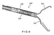
図5および図6に示されるように、代替的な実施形態による装置200’は、装置200と概ね同様である。しかしながら、装置200’は、カプセルの外部周辺の導電性コイルではなく、むしろカプセル206’の内面周辺に延びて、カプセル206’の中に摺動可能に受け入れられるクリップ・アーム204’を活性化させるための電界を生成させる導電性コイル264’を備える。図示されていない別の実施形態において、導電性コイルが、カプセル206’の壁部の中に埋め込まれていてもよい。 As shown in FIGS. 5 and 6,
装置200、200’は、装置100と概ね同様の様式で使用され得る。とりわけ、クリップ・アーム204、204’は、上述のように、組織を焼灼、凝固、挟持の少なくとも何れか1つのために使用され得る。 The
本発明の要旨及び範囲から逸脱することなく、本発明の構造及び方法について変更可能である。したがって、本発明は、当業者によって企図され得るこの開示の修正例及び変形例をカバーすることが意図されている。 Changes may be made in the structure and method of the present invention without departing from the spirit or scope of the invention. Therefore, the present invention is intended to cover modifications and variations of this disclosure that may be contemplated by those skilled in the art.
Claims (13)
Translated fromJapanese近位端部が、前記カプセルの前記チャネルの中に摺動可能に受け入れられ、遠位端部が、相互に離間するように前記カプセルの遠位端部を越えて遠位側に延出する開配置と、相互に引き寄せられるように前記カプセルの内面によって拘束される閉配置との間で移動可能な一対のクリップ・アームと、
前記一対のクリップ・アームに連結され、予め設定された荷重を受けた場合に相互に分離するように、相互に解放可能に連結された近位部と遠位部とを含むコア部材と、
前記コア部材に連結され、近位端部が電流を前記一対のクリップ・アームに供給するために電源に接続された、導電性の制御部材と、を備え、
前記一対のクリップ・アームの一方である第1のクリップ・アームは、第1のクリップ・アーム被覆部と、第1のクリップ・アーム導電部とを含み、前記第1のクリップ・アーム導電部の第1の部分は、前記第1のクリップ・アームが通電された際に組織を焼灼するように構成され、前記第1のクリップ・アーム導電部の第2の部分は、前記第1のクリップ・アームが通電された際に組織を凝固するように構成される、組織治療のための装置。A capsule that includes a channel extending longitudinally from the proximal end to the distal end and extending the entire length and is releasably coupled to the proximal portion of the device;
A proximal end is slidably received in the channel of the capsule and a distal end extends distally beyond the distal end of the capsule so as to be spaced apart from each other. A pair of clip arms moveable between an open configuration and a closed configuration constrained by the inner surface of the capsule to be drawn together.
A core member coupled to the pair of clip arms and including a proximal portion and a distal portion releasably coupled to each other so as to separate from each other when subjected to a preset load;
A conductive control member coupled to the core member and having a proximal end connected to a power source for supplying current to the pair of clip arms.
A first clip arm,which is one of the pair of cliparms, includes a first clip arm covering portion and a first clip arm conductive portion, and the first clip arm conductive portion includes a first clip arm conductive portion. the first portion, thefirst clip arm is configured to ablate tissue when energized, a second portion of the first clip arm conductive portion, saidfirst clip A device for tissue treatment configured to coagulate tissue when an arm is energized.
前記近位部から配置可能になるように前記近位部に解放可能に連結された遠位部と、
を備え、前記遠位部は、
前記ブッシングに解放可能に連結され、近位端部から遠位端部へ長手方向に延びるとともに全長にわたって延びるチャネルを含むカプセルと、
近位端部から延び、前記カプセルの前記チャネルの中に摺動可能に受け入れられる一対のクリップ・アームと、を含み、前記一対のクリップ・アームは、当該一対のクリップ・アームの遠位端部が相互に離間するように前記カプセルの前記遠位端部を越えて遠位側に延びる開配置と、当該一対のクリップ・アームの前記遠位端部が相互に引き寄せられるように前記一対のクリップ・アームが前記カプセルの内面によって拘束される閉配置との間で移動可能であり、
前記一対のクリップ・アームの近位端部に連結され、予め設定された荷重を受けた場合に機能しなくなるように設計された破壊可能なリンクによって相互に連結された近位部と遠位部とを含むコア部材と、
前記コア部材に連結され、近位端部が電流を前記一対のクリップ・アームに供給するために電源に接続された導電性の制御ワイヤと、を備え、
前記一対のクリップ・アームの一方である第1のクリップ・アームは、第1のクリップ・アーム被覆部と、第1のクリップ・アーム導電部とを含み、前記第1のクリップ・アーム導電部の第1の部分は、前記第1のクリップ・アームが通電された際に組織を焼灼するように構成され、前記第1のクリップ・アーム導電部の第2の部分は、前記第1のクリップ・アームが通電された際に組織を凝固するように構成される、クリッピング装置。A proximal portion including a flexible member extending longitudinally from the proximal end to the distal end and a bushing coupled to the distal end of the flexible member;
A distal portion releasably coupled to the proximal portion such that it can be deployed from the proximal portion,
And the distal portion comprises
A capsule releasably coupled to the bushing and comprising a channel extending longitudinally from the proximal end to the distal end and extending the entire length,
A pair of clip arms extending from the proximal ends and slidably received in the channels of the capsule, the pair of clip arms being at the distal ends of the pair of clip arms. An open arrangement extending distally beyond the distal ends of the capsules so that they are spaced apart from each other, and the pair of clips so that the distal ends of the pair of clip arms are drawn together. The arm being moveable between a closed configuration in which it is constrained by the inner surface of the capsule,
A proximal portion and a distal portion connected to the proximal ends of the pair of clip arms and interconnected by a breakable link designed to fail when subjected to a preset load. A core member including and
A conductive control wire coupled to the core member and having a proximal end connected to a power source to supply current to the pair of clip arms;
A first clip arm,which is one of the pair of cliparms, includes a first clip arm covering portion and a first clip arm conductive portion, and the first clip arm conductive portion includes a first clip arm conductive portion. the first portion, thefirst clip arm is configured to ablate tissue when energized, a second portion of the first clip arm conductive portion, saidfirst clip A clipping device configured to coagulate tissue when the arm is energized.
Applications Claiming Priority (3)
| Application Number | Priority Date | Filing Date | Title |
|---|---|---|---|
| US201562262729P | 2015-12-03 | 2015-12-03 | |
| US62/262,729 | 2015-12-03 | ||
| PCT/US2016/062063WO2017095626A1 (en) | 2015-12-03 | 2016-11-15 | Electrocautery hemostasis clip |
Publications (2)
| Publication Number | Publication Date |
|---|---|
| JP2018534994A JP2018534994A (en) | 2018-11-29 |
| JP6682627B2true JP6682627B2 (en) | 2020-04-15 |
Family
ID=57460605
Family Applications (1)
| Application Number | Title | Priority Date | Filing Date |
|---|---|---|---|
| JP2018521593AActiveJP6682627B2 (en) | 2015-12-03 | 2016-11-15 | Electrocautery hemostatic clip |
Country Status (6)
| Country | Link |
|---|---|
| US (2) | US10307202B2 (en) |
| EP (2) | EP3359060B1 (en) |
| JP (1) | JP6682627B2 (en) |
| CN (2) | CN108289686B (en) |
| AU (1) | AU2016364950B2 (en) |
| WO (1) | WO2017095626A1 (en) |
Families Citing this family (398)
| Publication number | Priority date | Publication date | Assignee | Title |
|---|---|---|---|---|
| US20070084897A1 (en) | 2003-05-20 | 2007-04-19 | Shelton Frederick E Iv | Articulating surgical stapling instrument incorporating a two-piece e-beam firing mechanism |
| US9060770B2 (en) | 2003-05-20 | 2015-06-23 | Ethicon Endo-Surgery, Inc. | Robotically-driven surgical instrument with E-beam driver |
| US11998198B2 (en) | 2004-07-28 | 2024-06-04 | Cilag Gmbh International | Surgical stapling instrument incorporating a two-piece E-beam firing mechanism |
| US8215531B2 (en) | 2004-07-28 | 2012-07-10 | Ethicon Endo-Surgery, Inc. | Surgical stapling instrument having a medical substance dispenser |
| US11890012B2 (en) | 2004-07-28 | 2024-02-06 | Cilag Gmbh International | Staple cartridge comprising cartridge body and attached support |
| US9072535B2 (en) | 2011-05-27 | 2015-07-07 | Ethicon Endo-Surgery, Inc. | Surgical stapling instruments with rotatable staple deployment arrangements |
| US7934630B2 (en) | 2005-08-31 | 2011-05-03 | Ethicon Endo-Surgery, Inc. | Staple cartridges for forming staples having differing formed staple heights |
| US7669746B2 (en) | 2005-08-31 | 2010-03-02 | Ethicon Endo-Surgery, Inc. | Staple cartridges for forming staples having differing formed staple heights |
| US11246590B2 (en) | 2005-08-31 | 2022-02-15 | Cilag Gmbh International | Staple cartridge including staple drivers having different unfired heights |
| US9237891B2 (en) | 2005-08-31 | 2016-01-19 | Ethicon Endo-Surgery, Inc. | Robotically-controlled surgical stapling devices that produce formed staples having different lengths |
| US10159482B2 (en) | 2005-08-31 | 2018-12-25 | Ethicon Llc | Fastener cartridge assembly comprising a fixed anvil and different staple heights |
| US11484312B2 (en) | 2005-08-31 | 2022-11-01 | Cilag Gmbh International | Staple cartridge comprising a staple driver arrangement |
| US20070106317A1 (en) | 2005-11-09 | 2007-05-10 | Shelton Frederick E Iv | Hydraulically and electrically actuated articulation joints for surgical instruments |
| US8708213B2 (en) | 2006-01-31 | 2014-04-29 | Ethicon Endo-Surgery, Inc. | Surgical instrument having a feedback system |
| US20110295295A1 (en) | 2006-01-31 | 2011-12-01 | Ethicon Endo-Surgery, Inc. | Robotically-controlled surgical instrument having recording capabilities |
| US7845537B2 (en) | 2006-01-31 | 2010-12-07 | Ethicon Endo-Surgery, Inc. | Surgical instrument having recording capabilities |
| US11793518B2 (en) | 2006-01-31 | 2023-10-24 | Cilag Gmbh International | Powered surgical instruments with firing system lockout arrangements |
| US11278279B2 (en) | 2006-01-31 | 2022-03-22 | Cilag Gmbh International | Surgical instrument assembly |
| US8820603B2 (en) | 2006-01-31 | 2014-09-02 | Ethicon Endo-Surgery, Inc. | Accessing data stored in a memory of a surgical instrument |
| US8186555B2 (en) | 2006-01-31 | 2012-05-29 | Ethicon Endo-Surgery, Inc. | Motor-driven surgical cutting and fastening instrument with mechanical closure system |
| US20120292367A1 (en) | 2006-01-31 | 2012-11-22 | Ethicon Endo-Surgery, Inc. | Robotically-controlled end effector |
| US7753904B2 (en) | 2006-01-31 | 2010-07-13 | Ethicon Endo-Surgery, Inc. | Endoscopic surgical instrument with a handle that can articulate with respect to the shaft |
| US20110024477A1 (en) | 2009-02-06 | 2011-02-03 | Hall Steven G | Driven Surgical Stapler Improvements |
| US11224427B2 (en) | 2006-01-31 | 2022-01-18 | Cilag Gmbh International | Surgical stapling system including a console and retraction assembly |
| US8992422B2 (en) | 2006-03-23 | 2015-03-31 | Ethicon Endo-Surgery, Inc. | Robotically-controlled endoscopic accessory channel |
| US8322455B2 (en) | 2006-06-27 | 2012-12-04 | Ethicon Endo-Surgery, Inc. | Manually driven surgical cutting and fastening instrument |
| US10568652B2 (en) | 2006-09-29 | 2020-02-25 | Ethicon Llc | Surgical staples having attached drivers of different heights and stapling instruments for deploying the same |
| US11980366B2 (en) | 2006-10-03 | 2024-05-14 | Cilag Gmbh International | Surgical instrument |
| US8684253B2 (en) | 2007-01-10 | 2014-04-01 | Ethicon Endo-Surgery, Inc. | Surgical instrument with wireless communication between a control unit of a robotic system and remote sensor |
| US11291441B2 (en) | 2007-01-10 | 2022-04-05 | Cilag Gmbh International | Surgical instrument with wireless communication between control unit and remote sensor |
| US8632535B2 (en) | 2007-01-10 | 2014-01-21 | Ethicon Endo-Surgery, Inc. | Interlock and surgical instrument including same |
| US20080169333A1 (en) | 2007-01-11 | 2008-07-17 | Shelton Frederick E | Surgical stapler end effector with tapered distal end |
| US11039836B2 (en) | 2007-01-11 | 2021-06-22 | Cilag Gmbh International | Staple cartridge for use with a surgical stapling instrument |
| US7673782B2 (en) | 2007-03-15 | 2010-03-09 | Ethicon Endo-Surgery, Inc. | Surgical stapling instrument having a releasable buttress material |
| US11564682B2 (en) | 2007-06-04 | 2023-01-31 | Cilag Gmbh International | Surgical stapler device |
| US8931682B2 (en) | 2007-06-04 | 2015-01-13 | Ethicon Endo-Surgery, Inc. | Robotically-controlled shaft based rotary drive systems for surgical instruments |
| US7753245B2 (en) | 2007-06-22 | 2010-07-13 | Ethicon Endo-Surgery, Inc. | Surgical stapling instruments |
| US11849941B2 (en) | 2007-06-29 | 2023-12-26 | Cilag Gmbh International | Staple cartridge having staple cavities extending at a transverse angle relative to a longitudinal cartridge axis |
| US8636736B2 (en) | 2008-02-14 | 2014-01-28 | Ethicon Endo-Surgery, Inc. | Motorized surgical cutting and fastening instrument |
| US7819298B2 (en) | 2008-02-14 | 2010-10-26 | Ethicon Endo-Surgery, Inc. | Surgical stapling apparatus with control features operable with one hand |
| US7866527B2 (en) | 2008-02-14 | 2011-01-11 | Ethicon Endo-Surgery, Inc. | Surgical stapling apparatus with interlockable firing system |
| US8758391B2 (en) | 2008-02-14 | 2014-06-24 | Ethicon Endo-Surgery, Inc. | Interchangeable tools for surgical instruments |
| US8573465B2 (en) | 2008-02-14 | 2013-11-05 | Ethicon Endo-Surgery, Inc. | Robotically-controlled surgical end effector system with rotary actuated closure systems |
| US9179912B2 (en) | 2008-02-14 | 2015-11-10 | Ethicon Endo-Surgery, Inc. | Robotically-controlled motorized surgical cutting and fastening instrument |
| US11986183B2 (en) | 2008-02-14 | 2024-05-21 | Cilag Gmbh International | Surgical cutting and fastening instrument comprising a plurality of sensors to measure an electrical parameter |
| JP5410110B2 (en) | 2008-02-14 | 2014-02-05 | エシコン・エンド−サージェリィ・インコーポレイテッド | Surgical cutting / fixing instrument with RF electrode |
| US9585657B2 (en) | 2008-02-15 | 2017-03-07 | Ethicon Endo-Surgery, Llc | Actuator for releasing a layer of material from a surgical end effector |
| US9386983B2 (en) | 2008-09-23 | 2016-07-12 | Ethicon Endo-Surgery, Llc | Robotically-controlled motorized surgical instrument |
| US8210411B2 (en) | 2008-09-23 | 2012-07-03 | Ethicon Endo-Surgery, Inc. | Motor-driven surgical cutting instrument |
| US11648005B2 (en) | 2008-09-23 | 2023-05-16 | Cilag Gmbh International | Robotically-controlled motorized surgical instrument with an end effector |
| US9005230B2 (en) | 2008-09-23 | 2015-04-14 | Ethicon Endo-Surgery, Inc. | Motorized surgical instrument |
| US8608045B2 (en) | 2008-10-10 | 2013-12-17 | Ethicon Endo-Sugery, Inc. | Powered surgical cutting and stapling apparatus with manually retractable firing system |
| US8517239B2 (en) | 2009-02-05 | 2013-08-27 | Ethicon Endo-Surgery, Inc. | Surgical stapling instrument comprising a magnetic element driver |
| RU2525225C2 (en) | 2009-02-06 | 2014-08-10 | Этикон Эндо-Серджери, Инк. | Improvement of drive surgical suturing instrument |
| US8851354B2 (en) | 2009-12-24 | 2014-10-07 | Ethicon Endo-Surgery, Inc. | Surgical cutting instrument that analyzes tissue thickness |
| US8220688B2 (en) | 2009-12-24 | 2012-07-17 | Ethicon Endo-Surgery, Inc. | Motor-driven surgical cutting instrument with electric actuator directional control assembly |
| US8783543B2 (en) | 2010-07-30 | 2014-07-22 | Ethicon Endo-Surgery, Inc. | Tissue acquisition arrangements and methods for surgical stapling devices |
| US9351730B2 (en) | 2011-04-29 | 2016-05-31 | Ethicon Endo-Surgery, Llc | Tissue thickness compensator comprising channels |
| US9788834B2 (en) | 2010-09-30 | 2017-10-17 | Ethicon Llc | Layer comprising deployable attachment members |
| US9629814B2 (en) | 2010-09-30 | 2017-04-25 | Ethicon Endo-Surgery, Llc | Tissue thickness compensator configured to redistribute compressive forces |
| US10945731B2 (en) | 2010-09-30 | 2021-03-16 | Ethicon Llc | Tissue thickness compensator comprising controlled release and expansion |
| US9016542B2 (en) | 2010-09-30 | 2015-04-28 | Ethicon Endo-Surgery, Inc. | Staple cartridge comprising compressible distortion resistant components |
| US9386988B2 (en) | 2010-09-30 | 2016-07-12 | Ethicon End-Surgery, LLC | Retainer assembly including a tissue thickness compensator |
| US11812965B2 (en) | 2010-09-30 | 2023-11-14 | Cilag Gmbh International | Layer of material for a surgical end effector |
| US11925354B2 (en) | 2010-09-30 | 2024-03-12 | Cilag Gmbh International | Staple cartridge comprising staples positioned within a compressible portion thereof |
| US12213666B2 (en) | 2010-09-30 | 2025-02-04 | Cilag Gmbh International | Tissue thickness compensator comprising layers |
| US11298125B2 (en) | 2010-09-30 | 2022-04-12 | Cilag Gmbh International | Tissue stapler having a thickness compensator |
| US8695866B2 (en) | 2010-10-01 | 2014-04-15 | Ethicon Endo-Surgery, Inc. | Surgical instrument having a power control circuit |
| AU2012250197B2 (en) | 2011-04-29 | 2017-08-10 | Ethicon Endo-Surgery, Inc. | Staple cartridge comprising staples positioned within a compressible portion thereof |
| US11207064B2 (en) | 2011-05-27 | 2021-12-28 | Cilag Gmbh International | Automated end effector component reloading system for use with a robotic system |
| US9044230B2 (en) | 2012-02-13 | 2015-06-02 | Ethicon Endo-Surgery, Inc. | Surgical cutting and fastening instrument with apparatus for determining cartridge and firing motion status |
| BR112014024098B1 (en) | 2012-03-28 | 2021-05-25 | Ethicon Endo-Surgery, Inc. | staple cartridge |
| MX358135B (en) | 2012-03-28 | 2018-08-06 | Ethicon Endo Surgery Inc | Tissue thickness compensator comprising a plurality of layers. |
| JP6224070B2 (en) | 2012-03-28 | 2017-11-01 | エシコン・エンド−サージェリィ・インコーポレイテッドEthicon Endo−Surgery,Inc. | Retainer assembly including tissue thickness compensator |
| US9101358B2 (en) | 2012-06-15 | 2015-08-11 | Ethicon Endo-Surgery, Inc. | Articulatable surgical instrument comprising a firing drive |
| US12383267B2 (en) | 2012-06-28 | 2025-08-12 | Cilag Gmbh International | Robotically powered surgical device with manually-actuatable reversing system |
| JP6290201B2 (en) | 2012-06-28 | 2018-03-07 | エシコン・エンド−サージェリィ・インコーポレイテッドEthicon Endo−Surgery,Inc. | Lockout for empty clip cartridge |
| US9408606B2 (en) | 2012-06-28 | 2016-08-09 | Ethicon Endo-Surgery, Llc | Robotically powered surgical device with manually-actuatable reversing system |
| US20140005718A1 (en) | 2012-06-28 | 2014-01-02 | Ethicon Endo-Surgery, Inc. | Multi-functional powered surgical device with external dissection features |
| US20140001231A1 (en) | 2012-06-28 | 2014-01-02 | Ethicon Endo-Surgery, Inc. | Firing system lockout arrangements for surgical instruments |
| US11278284B2 (en) | 2012-06-28 | 2022-03-22 | Cilag Gmbh International | Rotary drive arrangements for surgical instruments |
| US9289256B2 (en) | 2012-06-28 | 2016-03-22 | Ethicon Endo-Surgery, Llc | Surgical end effectors having angled tissue-contacting surfaces |
| US9282974B2 (en) | 2012-06-28 | 2016-03-15 | Ethicon Endo-Surgery, Llc | Empty clip cartridge lockout |
| BR112014032776B1 (en) | 2012-06-28 | 2021-09-08 | Ethicon Endo-Surgery, Inc | SURGICAL INSTRUMENT SYSTEM AND SURGICAL KIT FOR USE WITH A SURGICAL INSTRUMENT SYSTEM |
| BR112015021082B1 (en) | 2013-03-01 | 2022-05-10 | Ethicon Endo-Surgery, Inc | surgical instrument |
| RU2672520C2 (en) | 2013-03-01 | 2018-11-15 | Этикон Эндо-Серджери, Инк. | Hingedly turnable surgical instruments with conducting ways for signal transfer |
| US9629629B2 (en) | 2013-03-14 | 2017-04-25 | Ethicon Endo-Surgey, LLC | Control systems for surgical instruments |
| US9808244B2 (en) | 2013-03-14 | 2017-11-07 | Ethicon Llc | Sensor arrangements for absolute positioning system for surgical instruments |
| BR112015026109B1 (en) | 2013-04-16 | 2022-02-22 | Ethicon Endo-Surgery, Inc | surgical instrument |
| US9826976B2 (en) | 2013-04-16 | 2017-11-28 | Ethicon Llc | Motor driven surgical instruments with lockable dual drive shafts |
| US9775609B2 (en) | 2013-08-23 | 2017-10-03 | Ethicon Llc | Tamper proof circuit for surgical instrument battery pack |
| MX369362B (en) | 2013-08-23 | 2019-11-06 | Ethicon Endo Surgery Llc | Firing member retraction devices for powered surgical instruments. |
| US9962161B2 (en) | 2014-02-12 | 2018-05-08 | Ethicon Llc | Deliverable surgical instrument |
| US20150272580A1 (en) | 2014-03-26 | 2015-10-01 | Ethicon Endo-Surgery, Inc. | Verification of number of battery exchanges/procedure count |
| BR112016021943B1 (en) | 2014-03-26 | 2022-06-14 | Ethicon Endo-Surgery, Llc | SURGICAL INSTRUMENT FOR USE BY AN OPERATOR IN A SURGICAL PROCEDURE |
| US10004497B2 (en) | 2014-03-26 | 2018-06-26 | Ethicon Llc | Interface systems for use with surgical instruments |
| US10013049B2 (en) | 2014-03-26 | 2018-07-03 | Ethicon Llc | Power management through sleep options of segmented circuit and wake up control |
| US12232723B2 (en) | 2014-03-26 | 2025-02-25 | Cilag Gmbh International | Systems and methods for controlling a segmented circuit |
| US10327764B2 (en) | 2014-09-26 | 2019-06-25 | Ethicon Llc | Method for creating a flexible staple line |
| CN106456159B (en) | 2014-04-16 | 2019-03-08 | 伊西康内外科有限责任公司 | Fastener Cartridge Assembly and Nail Retainer Cover Arrangement |
| CN106456176B (en) | 2014-04-16 | 2019-06-28 | 伊西康内外科有限责任公司 | Fastener Cartridge Including Extensions With Different Configurations |
| US20150297225A1 (en) | 2014-04-16 | 2015-10-22 | Ethicon Endo-Surgery, Inc. | Fastener cartridges including extensions having different configurations |
| BR112016023825B1 (en) | 2014-04-16 | 2022-08-02 | Ethicon Endo-Surgery, Llc | STAPLE CARTRIDGE FOR USE WITH A SURGICAL STAPLER AND STAPLE CARTRIDGE FOR USE WITH A SURGICAL INSTRUMENT |
| US10470768B2 (en) | 2014-04-16 | 2019-11-12 | Ethicon Llc | Fastener cartridge including a layer attached thereto |
| US11311294B2 (en) | 2014-09-05 | 2022-04-26 | Cilag Gmbh International | Powered medical device including measurement of closure state of jaws |
| BR112017004361B1 (en) | 2014-09-05 | 2023-04-11 | Ethicon Llc | ELECTRONIC SYSTEM FOR A SURGICAL INSTRUMENT |
| US10135242B2 (en) | 2014-09-05 | 2018-11-20 | Ethicon Llc | Smart cartridge wake up operation and data retention |
| US10105142B2 (en) | 2014-09-18 | 2018-10-23 | Ethicon Llc | Surgical stapler with plurality of cutting elements |
| US11523821B2 (en) | 2014-09-26 | 2022-12-13 | Cilag Gmbh International | Method for creating a flexible staple line |
| CN107427300B (en) | 2014-09-26 | 2020-12-04 | 伊西康有限责任公司 | Surgical suture buttresses and auxiliary materials |
| US10076325B2 (en) | 2014-10-13 | 2018-09-18 | Ethicon Llc | Surgical stapling apparatus comprising a tissue stop |
| US9924944B2 (en) | 2014-10-16 | 2018-03-27 | Ethicon Llc | Staple cartridge comprising an adjunct material |
| US11141153B2 (en) | 2014-10-29 | 2021-10-12 | Cilag Gmbh International | Staple cartridges comprising driver arrangements |
| US10517594B2 (en) | 2014-10-29 | 2019-12-31 | Ethicon Llc | Cartridge assemblies for surgical staplers |
| US9844376B2 (en) | 2014-11-06 | 2017-12-19 | Ethicon Llc | Staple cartridge comprising a releasable adjunct material |
| US10736636B2 (en) | 2014-12-10 | 2020-08-11 | Ethicon Llc | Articulatable surgical instrument system |
| MX389118B (en) | 2014-12-18 | 2025-03-20 | Ethicon Llc | SURGICAL INSTRUMENT WITH AN ANVIL THAT CAN BE SELECTIVELY MOVED ON A DISCRETE, NON-MOBILE AXIS RELATIVE TO A STAPLE CARTRIDGE. |
| US10085748B2 (en) | 2014-12-18 | 2018-10-02 | Ethicon Llc | Locking arrangements for detachable shaft assemblies with articulatable surgical end effectors |
| US9844375B2 (en) | 2014-12-18 | 2017-12-19 | Ethicon Llc | Drive arrangements for articulatable surgical instruments |
| US9987000B2 (en) | 2014-12-18 | 2018-06-05 | Ethicon Llc | Surgical instrument assembly comprising a flexible articulation system |
| US9943309B2 (en) | 2014-12-18 | 2018-04-17 | Ethicon Llc | Surgical instruments with articulatable end effectors and movable firing beam support arrangements |
| US9844374B2 (en) | 2014-12-18 | 2017-12-19 | Ethicon Llc | Surgical instrument systems comprising an articulatable end effector and means for adjusting the firing stroke of a firing member |
| US11154301B2 (en) | 2015-02-27 | 2021-10-26 | Cilag Gmbh International | Modular stapling assembly |
| JP2020121162A (en) | 2015-03-06 | 2020-08-13 | エシコン エルエルシーEthicon LLC | Time dependent evaluation of sensor data to determine stability element, creep element and viscoelastic element of measurement |
| US10441279B2 (en) | 2015-03-06 | 2019-10-15 | Ethicon Llc | Multiple level thresholds to modify operation of powered surgical instruments |
| US10687806B2 (en) | 2015-03-06 | 2020-06-23 | Ethicon Llc | Adaptive tissue compression techniques to adjust closure rates for multiple tissue types |
| US9901342B2 (en) | 2015-03-06 | 2018-02-27 | Ethicon Endo-Surgery, Llc | Signal and power communication system positioned on a rotatable shaft |
| US10548504B2 (en) | 2015-03-06 | 2020-02-04 | Ethicon Llc | Overlaid multi sensor radio frequency (RF) electrode system to measure tissue compression |
| US9924961B2 (en) | 2015-03-06 | 2018-03-27 | Ethicon Endo-Surgery, Llc | Interactive feedback system for powered surgical instruments |
| US9993248B2 (en) | 2015-03-06 | 2018-06-12 | Ethicon Endo-Surgery, Llc | Smart sensors with local signal processing |
| US10245033B2 (en) | 2015-03-06 | 2019-04-02 | Ethicon Llc | Surgical instrument comprising a lockable battery housing |
| US10617412B2 (en) | 2015-03-06 | 2020-04-14 | Ethicon Llc | System for detecting the mis-insertion of a staple cartridge into a surgical stapler |
| US10433844B2 (en) | 2015-03-31 | 2019-10-08 | Ethicon Llc | Surgical instrument with selectively disengageable threaded drive systems |
| US10835249B2 (en) | 2015-08-17 | 2020-11-17 | Ethicon Llc | Implantable layers for a surgical instrument |
| US10105139B2 (en) | 2015-09-23 | 2018-10-23 | Ethicon Llc | Surgical stapler having downstream current-based motor control |
| US10238386B2 (en) | 2015-09-23 | 2019-03-26 | Ethicon Llc | Surgical stapler having motor control based on an electrical parameter related to a motor current |
| US10299878B2 (en) | 2015-09-25 | 2019-05-28 | Ethicon Llc | Implantable adjunct systems for determining adjunct skew |
| US11890015B2 (en) | 2015-09-30 | 2024-02-06 | Cilag Gmbh International | Compressible adjunct with crossing spacer fibers |
| US10478188B2 (en) | 2015-09-30 | 2019-11-19 | Ethicon Llc | Implantable layer comprising a constricted configuration |
| US10433846B2 (en) | 2015-09-30 | 2019-10-08 | Ethicon Llc | Compressible adjunct with crossing spacer fibers |
| US10980539B2 (en) | 2015-09-30 | 2021-04-20 | Ethicon Llc | Implantable adjunct comprising bonded layers |
| US10368865B2 (en) | 2015-12-30 | 2019-08-06 | Ethicon Llc | Mechanisms for compensating for drivetrain failure in powered surgical instruments |
| US10292704B2 (en) | 2015-12-30 | 2019-05-21 | Ethicon Llc | Mechanisms for compensating for battery pack failure in powered surgical instruments |
| US10265068B2 (en) | 2015-12-30 | 2019-04-23 | Ethicon Llc | Surgical instruments with separable motors and motor control circuits |
| US11213293B2 (en) | 2016-02-09 | 2022-01-04 | Cilag Gmbh International | Articulatable surgical instruments with single articulation link arrangements |
| BR112018016098B1 (en) | 2016-02-09 | 2023-02-23 | Ethicon Llc | SURGICAL INSTRUMENT |
| US10413291B2 (en) | 2016-02-09 | 2019-09-17 | Ethicon Llc | Surgical instrument articulation mechanism with slotted secondary constraint |
| US11224426B2 (en) | 2016-02-12 | 2022-01-18 | Cilag Gmbh International | Mechanisms for compensating for drivetrain failure in powered surgical instruments |
| US10448948B2 (en) | 2016-02-12 | 2019-10-22 | Ethicon Llc | Mechanisms for compensating for drivetrain failure in powered surgical instruments |
| US10617413B2 (en) | 2016-04-01 | 2020-04-14 | Ethicon Llc | Closure system arrangements for surgical cutting and stapling devices with separate and distinct firing shafts |
| US10492783B2 (en) | 2016-04-15 | 2019-12-03 | Ethicon, Llc | Surgical instrument with improved stop/start control during a firing motion |
| US10828028B2 (en) | 2016-04-15 | 2020-11-10 | Ethicon Llc | Surgical instrument with multiple program responses during a firing motion |
| US10456137B2 (en) | 2016-04-15 | 2019-10-29 | Ethicon Llc | Staple formation detection mechanisms |
| US11179150B2 (en) | 2016-04-15 | 2021-11-23 | Cilag Gmbh International | Systems and methods for controlling a surgical stapling and cutting instrument |
| US10426467B2 (en) | 2016-04-15 | 2019-10-01 | Ethicon Llc | Surgical instrument with detection sensors |
| US10335145B2 (en) | 2016-04-15 | 2019-07-02 | Ethicon Llc | Modular surgical instrument with configurable operating mode |
| US10357247B2 (en) | 2016-04-15 | 2019-07-23 | Ethicon Llc | Surgical instrument with multiple program responses during a firing motion |
| US11607239B2 (en) | 2016-04-15 | 2023-03-21 | Cilag Gmbh International | Systems and methods for controlling a surgical stapling and cutting instrument |
| US20170296173A1 (en) | 2016-04-18 | 2017-10-19 | Ethicon Endo-Surgery, Llc | Method for operating a surgical instrument |
| US10363037B2 (en) | 2016-04-18 | 2019-07-30 | Ethicon Llc | Surgical instrument system comprising a magnetic lockout |
| US11317917B2 (en) | 2016-04-18 | 2022-05-03 | Cilag Gmbh International | Surgical stapling system comprising a lockable firing assembly |
| US10500000B2 (en) | 2016-08-16 | 2019-12-10 | Ethicon Llc | Surgical tool with manual control of end effector jaws |
| US10980536B2 (en) | 2016-12-21 | 2021-04-20 | Ethicon Llc | No-cartridge and spent cartridge lockout arrangements for surgical staplers |
| US10813638B2 (en) | 2016-12-21 | 2020-10-27 | Ethicon Llc | Surgical end effectors with expandable tissue stop arrangements |
| MX2019007295A (en) | 2016-12-21 | 2019-10-15 | Ethicon Llc | Surgical instrument system comprising an end effector lockout and a firing assembly lockout. |
| US20180168625A1 (en) | 2016-12-21 | 2018-06-21 | Ethicon Endo-Surgery, Llc | Surgical stapling instruments with smart staple cartridges |
| JP2020501815A (en) | 2016-12-21 | 2020-01-23 | エシコン エルエルシーEthicon LLC | Surgical stapling system |
| US10568625B2 (en) | 2016-12-21 | 2020-02-25 | Ethicon Llc | Staple cartridges and arrangements of staples and staple cavities therein |
| JP6983893B2 (en) | 2016-12-21 | 2021-12-17 | エシコン エルエルシーEthicon LLC | Lockout configuration for surgical end effectors and replaceable tool assemblies |
| US20180168615A1 (en) | 2016-12-21 | 2018-06-21 | Ethicon Endo-Surgery, Llc | Method of deforming staples from two different types of staple cartridges with the same surgical stapling instrument |
| US11134942B2 (en) | 2016-12-21 | 2021-10-05 | Cilag Gmbh International | Surgical stapling instruments and staple-forming anvils |
| US10758229B2 (en) | 2016-12-21 | 2020-09-01 | Ethicon Llc | Surgical instrument comprising improved jaw control |
| CN110087565A (en) | 2016-12-21 | 2019-08-02 | 爱惜康有限责任公司 | Surgical stapling system |
| US10695055B2 (en)* | 2016-12-21 | 2020-06-30 | Ethicon Llc | Firing assembly comprising a lockout |
| JP7010956B2 (en) | 2016-12-21 | 2022-01-26 | エシコン エルエルシー | How to staple tissue |
| JP7010957B2 (en) | 2016-12-21 | 2022-01-26 | エシコン エルエルシー | Shaft assembly with lockout |
| US10485543B2 (en) | 2016-12-21 | 2019-11-26 | Ethicon Llc | Anvil having a knife slot width |
| US10898186B2 (en) | 2016-12-21 | 2021-01-26 | Ethicon Llc | Staple forming pocket arrangements comprising primary sidewalls and pocket sidewalls |
| US10973516B2 (en) | 2016-12-21 | 2021-04-13 | Ethicon Llc | Surgical end effectors and adaptable firing members therefor |
| US11090048B2 (en) | 2016-12-21 | 2021-08-17 | Cilag Gmbh International | Method for resetting a fuse of a surgical instrument shaft |
| US11419606B2 (en) | 2016-12-21 | 2022-08-23 | Cilag Gmbh International | Shaft assembly comprising a clutch configured to adapt the output of a rotary firing member to two different systems |
| US10582928B2 (en) | 2016-12-21 | 2020-03-10 | Ethicon Llc | Articulation lock arrangements for locking an end effector in an articulated position in response to actuation of a jaw closure system |
| US10542982B2 (en) | 2016-12-21 | 2020-01-28 | Ethicon Llc | Shaft assembly comprising first and second articulation lockouts |
| US10888321B2 (en) | 2017-06-20 | 2021-01-12 | Ethicon Llc | Systems and methods for controlling velocity of a displacement member of a surgical stapling and cutting instrument |
| US10779820B2 (en) | 2017-06-20 | 2020-09-22 | Ethicon Llc | Systems and methods for controlling motor speed according to user input for a surgical instrument |
| US11071554B2 (en) | 2017-06-20 | 2021-07-27 | Cilag Gmbh International | Closed loop feedback control of motor velocity of a surgical stapling and cutting instrument based on magnitude of velocity error measurements |
| US10980537B2 (en) | 2017-06-20 | 2021-04-20 | Ethicon Llc | Closed loop feedback control of motor velocity of a surgical stapling and cutting instrument based on measured time over a specified number of shaft rotations |
| USD890784S1 (en) | 2017-06-20 | 2020-07-21 | Ethicon Llc | Display panel with changeable graphical user interface |
| US10813639B2 (en) | 2017-06-20 | 2020-10-27 | Ethicon Llc | Closed loop feedback control of motor velocity of a surgical stapling and cutting instrument based on system conditions |
| USD879808S1 (en) | 2017-06-20 | 2020-03-31 | Ethicon Llc | Display panel with graphical user interface |
| US10624633B2 (en) | 2017-06-20 | 2020-04-21 | Ethicon Llc | Systems and methods for controlling motor velocity of a surgical stapling and cutting instrument |
| US10881399B2 (en) | 2017-06-20 | 2021-01-05 | Ethicon Llc | Techniques for adaptive control of motor velocity of a surgical stapling and cutting instrument |
| US10881396B2 (en) | 2017-06-20 | 2021-01-05 | Ethicon Llc | Surgical instrument with variable duration trigger arrangement |
| USD879809S1 (en) | 2017-06-20 | 2020-03-31 | Ethicon Llc | Display panel with changeable graphical user interface |
| US11517325B2 (en) | 2017-06-20 | 2022-12-06 | Cilag Gmbh International | Closed loop feedback control of motor velocity of a surgical stapling and cutting instrument based on measured displacement distance traveled over a specified time interval |
| US11382638B2 (en) | 2017-06-20 | 2022-07-12 | Cilag Gmbh International | Closed loop feedback control of motor velocity of a surgical stapling and cutting instrument based on measured time over a specified displacement distance |
| US11653914B2 (en) | 2017-06-20 | 2023-05-23 | Cilag Gmbh International | Systems and methods for controlling motor velocity of a surgical stapling and cutting instrument according to articulation angle of end effector |
| US11090046B2 (en) | 2017-06-20 | 2021-08-17 | Cilag Gmbh International | Systems and methods for controlling displacement member motion of a surgical stapling and cutting instrument |
| US10307170B2 (en) | 2017-06-20 | 2019-06-04 | Ethicon Llc | Method for closed loop control of motor velocity of a surgical stapling and cutting instrument |
| US10646220B2 (en) | 2017-06-20 | 2020-05-12 | Ethicon Llc | Systems and methods for controlling displacement member velocity for a surgical instrument |
| US10772629B2 (en) | 2017-06-27 | 2020-09-15 | Ethicon Llc | Surgical anvil arrangements |
| US10993716B2 (en) | 2017-06-27 | 2021-05-04 | Ethicon Llc | Surgical anvil arrangements |
| US11266405B2 (en) | 2017-06-27 | 2022-03-08 | Cilag Gmbh International | Surgical anvil manufacturing methods |
| US10856869B2 (en) | 2017-06-27 | 2020-12-08 | Ethicon Llc | Surgical anvil arrangements |
| US11090049B2 (en) | 2017-06-27 | 2021-08-17 | Cilag Gmbh International | Staple forming pocket arrangements |
| US11324503B2 (en) | 2017-06-27 | 2022-05-10 | Cilag Gmbh International | Surgical firing member arrangements |
| US11484310B2 (en) | 2017-06-28 | 2022-11-01 | Cilag Gmbh International | Surgical instrument comprising a shaft including a closure tube profile |
| US10765427B2 (en) | 2017-06-28 | 2020-09-08 | Ethicon Llc | Method for articulating a surgical instrument |
| USD906355S1 (en) | 2017-06-28 | 2020-12-29 | Ethicon Llc | Display screen or portion thereof with a graphical user interface for a surgical instrument |
| US10716614B2 (en) | 2017-06-28 | 2020-07-21 | Ethicon Llc | Surgical shaft assemblies with slip ring assemblies with increased contact pressure |
| US11246592B2 (en) | 2017-06-28 | 2022-02-15 | Cilag Gmbh International | Surgical instrument comprising an articulation system lockable to a frame |
| EP3420947B1 (en) | 2017-06-28 | 2022-05-25 | Cilag GmbH International | Surgical instrument comprising selectively actuatable rotatable couplers |
| US11564686B2 (en) | 2017-06-28 | 2023-01-31 | Cilag Gmbh International | Surgical shaft assemblies with flexible interfaces |
| US10903685B2 (en) | 2017-06-28 | 2021-01-26 | Ethicon Llc | Surgical shaft assemblies with slip ring assemblies forming capacitive channels |
| US10758232B2 (en) | 2017-06-28 | 2020-09-01 | Ethicon Llc | Surgical instrument with positive jaw opening features |
| US11259805B2 (en) | 2017-06-28 | 2022-03-01 | Cilag Gmbh International | Surgical instrument comprising firing member supports |
| US10932772B2 (en) | 2017-06-29 | 2021-03-02 | Ethicon Llc | Methods for closed loop velocity control for robotic surgical instrument |
| US11007022B2 (en) | 2017-06-29 | 2021-05-18 | Ethicon Llc | Closed loop velocity control techniques based on sensed tissue parameters for robotic surgical instrument |
| US10898183B2 (en) | 2017-06-29 | 2021-01-26 | Ethicon Llc | Robotic surgical instrument with closed loop feedback techniques for advancement of closure member during firing |
| US11471155B2 (en) | 2017-08-03 | 2022-10-18 | Cilag Gmbh International | Surgical system bailout |
| US11944300B2 (en) | 2017-08-03 | 2024-04-02 | Cilag Gmbh International | Method for operating a surgical system bailout |
| US11974742B2 (en) | 2017-08-03 | 2024-05-07 | Cilag Gmbh International | Surgical system comprising an articulation bailout |
| US11304695B2 (en) | 2017-08-03 | 2022-04-19 | Cilag Gmbh International | Surgical system shaft interconnection |
| US10905434B2 (en) | 2017-09-28 | 2021-02-02 | Boston Scientific Scimed, Inc. | Reloadable and rotatable clip |
| US10729501B2 (en) | 2017-09-29 | 2020-08-04 | Ethicon Llc | Systems and methods for language selection of a surgical instrument |
| USD907648S1 (en) | 2017-09-29 | 2021-01-12 | Ethicon Llc | Display screen or portion thereof with animated graphical user interface |
| USD907647S1 (en) | 2017-09-29 | 2021-01-12 | Ethicon Llc | Display screen or portion thereof with animated graphical user interface |
| US11399829B2 (en) | 2017-09-29 | 2022-08-02 | Cilag Gmbh International | Systems and methods of initiating a power shutdown mode for a surgical instrument |
| USD917500S1 (en) | 2017-09-29 | 2021-04-27 | Ethicon Llc | Display screen or portion thereof with graphical user interface |
| US10765429B2 (en) | 2017-09-29 | 2020-09-08 | Ethicon Llc | Systems and methods for providing alerts according to the operational state of a surgical instrument |
| US10743872B2 (en) | 2017-09-29 | 2020-08-18 | Ethicon Llc | System and methods for controlling a display of a surgical instrument |
| US11090075B2 (en) | 2017-10-30 | 2021-08-17 | Cilag Gmbh International | Articulation features for surgical end effector |
| US11134944B2 (en) | 2017-10-30 | 2021-10-05 | Cilag Gmbh International | Surgical stapler knife motion controls |
| US10779903B2 (en) | 2017-10-31 | 2020-09-22 | Ethicon Llc | Positive shaft rotation lock activated by jaw closure |
| US10842490B2 (en) | 2017-10-31 | 2020-11-24 | Ethicon Llc | Cartridge body design with force reduction based on firing completion |
| US10869666B2 (en) | 2017-12-15 | 2020-12-22 | Ethicon Llc | Adapters with control systems for controlling multiple motors of an electromechanical surgical instrument |
| US10779825B2 (en) | 2017-12-15 | 2020-09-22 | Ethicon Llc | Adapters with end effector position sensing and control arrangements for use in connection with electromechanical surgical instruments |
| US11071543B2 (en) | 2017-12-15 | 2021-07-27 | Cilag Gmbh International | Surgical end effectors with clamping assemblies configured to increase jaw aperture ranges |
| US10779826B2 (en) | 2017-12-15 | 2020-09-22 | Ethicon Llc | Methods of operating surgical end effectors |
| US11197670B2 (en) | 2017-12-15 | 2021-12-14 | Cilag Gmbh International | Surgical end effectors with pivotal jaws configured to touch at their respective distal ends when fully closed |
| US10966718B2 (en) | 2017-12-15 | 2021-04-06 | Ethicon Llc | Dynamic clamping assemblies with improved wear characteristics for use in connection with electromechanical surgical instruments |
| US10687813B2 (en) | 2017-12-15 | 2020-06-23 | Ethicon Llc | Adapters with firing stroke sensing arrangements for use in connection with electromechanical surgical instruments |
| US10743875B2 (en) | 2017-12-15 | 2020-08-18 | Ethicon Llc | Surgical end effectors with jaw stiffener arrangements configured to permit monitoring of firing member |
| US11006955B2 (en) | 2017-12-15 | 2021-05-18 | Ethicon Llc | End effectors with positive jaw opening features for use with adapters for electromechanical surgical instruments |
| US10828033B2 (en) | 2017-12-15 | 2020-11-10 | Ethicon Llc | Handheld electromechanical surgical instruments with improved motor control arrangements for positioning components of an adapter coupled thereto |
| US11033267B2 (en) | 2017-12-15 | 2021-06-15 | Ethicon Llc | Systems and methods of controlling a clamping member firing rate of a surgical instrument |
| US10743874B2 (en) | 2017-12-15 | 2020-08-18 | Ethicon Llc | Sealed adapters for use with electromechanical surgical instruments |
| USD910847S1 (en) | 2017-12-19 | 2021-02-16 | Ethicon Llc | Surgical instrument assembly |
| US10729509B2 (en) | 2017-12-19 | 2020-08-04 | Ethicon Llc | Surgical instrument comprising closure and firing locking mechanism |
| US11020112B2 (en) | 2017-12-19 | 2021-06-01 | Ethicon Llc | Surgical tools configured for interchangeable use with different controller interfaces |
| US10835330B2 (en) | 2017-12-19 | 2020-11-17 | Ethicon Llc | Method for determining the position of a rotatable jaw of a surgical instrument attachment assembly |
| US10716565B2 (en) | 2017-12-19 | 2020-07-21 | Ethicon Llc | Surgical instruments with dual articulation drivers |
| US11045270B2 (en) | 2017-12-19 | 2021-06-29 | Cilag Gmbh International | Robotic attachment comprising exterior drive actuator |
| US11179151B2 (en) | 2017-12-21 | 2021-11-23 | Cilag Gmbh International | Surgical instrument comprising a display |
| US12336705B2 (en) | 2017-12-21 | 2025-06-24 | Cilag Gmbh International | Continuous use self-propelled stapling instrument |
| US11076853B2 (en) | 2017-12-21 | 2021-08-03 | Cilag Gmbh International | Systems and methods of displaying a knife position during transection for a surgical instrument |
| US11311290B2 (en) | 2017-12-21 | 2022-04-26 | Cilag Gmbh International | Surgical instrument comprising an end effector dampener |
| US11129680B2 (en) | 2017-12-21 | 2021-09-28 | Cilag Gmbh International | Surgical instrument comprising a projector |
| USD914878S1 (en) | 2018-08-20 | 2021-03-30 | Ethicon Llc | Surgical instrument anvil |
| US11083458B2 (en) | 2018-08-20 | 2021-08-10 | Cilag Gmbh International | Powered surgical instruments with clutching arrangements to convert linear drive motions to rotary drive motions |
| US20200054321A1 (en) | 2018-08-20 | 2020-02-20 | Ethicon Llc | Surgical instruments with progressive jaw closure arrangements |
| US10856870B2 (en) | 2018-08-20 | 2020-12-08 | Ethicon Llc | Switching arrangements for motor powered articulatable surgical instruments |
| US11207065B2 (en) | 2018-08-20 | 2021-12-28 | Cilag Gmbh International | Method for fabricating surgical stapler anvils |
| US10912559B2 (en) | 2018-08-20 | 2021-02-09 | Ethicon Llc | Reinforced deformable anvil tip for surgical stapler anvil |
| US11253256B2 (en) | 2018-08-20 | 2022-02-22 | Cilag Gmbh International | Articulatable motor powered surgical instruments with dedicated articulation motor arrangements |
| US11045192B2 (en) | 2018-08-20 | 2021-06-29 | Cilag Gmbh International | Fabricating techniques for surgical stapler anvils |
| US10779821B2 (en) | 2018-08-20 | 2020-09-22 | Ethicon Llc | Surgical stapler anvils with tissue stop features configured to avoid tissue pinch |
| US11324501B2 (en) | 2018-08-20 | 2022-05-10 | Cilag Gmbh International | Surgical stapling devices with improved closure members |
| US11039834B2 (en) | 2018-08-20 | 2021-06-22 | Cilag Gmbh International | Surgical stapler anvils with staple directing protrusions and tissue stability features |
| US10842492B2 (en) | 2018-08-20 | 2020-11-24 | Ethicon Llc | Powered articulatable surgical instruments with clutching and locking arrangements for linking an articulation drive system to a firing drive system |
| US11291440B2 (en) | 2018-08-20 | 2022-04-05 | Cilag Gmbh International | Method for operating a powered articulatable surgical instrument |
| US11147551B2 (en) | 2019-03-25 | 2021-10-19 | Cilag Gmbh International | Firing drive arrangements for surgical systems |
| US11172929B2 (en) | 2019-03-25 | 2021-11-16 | Cilag Gmbh International | Articulation drive arrangements for surgical systems |
| US11147553B2 (en) | 2019-03-25 | 2021-10-19 | Cilag Gmbh International | Firing drive arrangements for surgical systems |
| US11696761B2 (en) | 2019-03-25 | 2023-07-11 | Cilag Gmbh International | Firing drive arrangements for surgical systems |
| CN110123408B (en)* | 2019-04-25 | 2025-05-13 | 安徽医科大学第一附属医院 | A chuck for a soft tissue clamp |
| US11432816B2 (en) | 2019-04-30 | 2022-09-06 | Cilag Gmbh International | Articulation pin for a surgical instrument |
| US11452528B2 (en) | 2019-04-30 | 2022-09-27 | Cilag Gmbh International | Articulation actuators for a surgical instrument |
| US11426251B2 (en) | 2019-04-30 | 2022-08-30 | Cilag Gmbh International | Articulation directional lights on a surgical instrument |
| US11471157B2 (en) | 2019-04-30 | 2022-10-18 | Cilag Gmbh International | Articulation control mapping for a surgical instrument |
| US11903581B2 (en) | 2019-04-30 | 2024-02-20 | Cilag Gmbh International | Methods for stapling tissue using a surgical instrument |
| US11253254B2 (en) | 2019-04-30 | 2022-02-22 | Cilag Gmbh International | Shaft rotation actuator on a surgical instrument |
| US11648009B2 (en) | 2019-04-30 | 2023-05-16 | Cilag Gmbh International | Rotatable jaw tip for a surgical instrument |
| US11241235B2 (en) | 2019-06-28 | 2022-02-08 | Cilag Gmbh International | Method of using multiple RFID chips with a surgical assembly |
| US11298127B2 (en) | 2019-06-28 | 2022-04-12 | Cilag GmbH Interational | Surgical stapling system having a lockout mechanism for an incompatible cartridge |
| US11638587B2 (en) | 2019-06-28 | 2023-05-02 | Cilag Gmbh International | RFID identification systems for surgical instruments |
| US11246678B2 (en) | 2019-06-28 | 2022-02-15 | Cilag Gmbh International | Surgical stapling system having a frangible RFID tag |
| US11464601B2 (en) | 2019-06-28 | 2022-10-11 | Cilag Gmbh International | Surgical instrument comprising an RFID system for tracking a movable component |
| US11497492B2 (en) | 2019-06-28 | 2022-11-15 | Cilag Gmbh International | Surgical instrument including an articulation lock |
| US11426167B2 (en) | 2019-06-28 | 2022-08-30 | Cilag Gmbh International | Mechanisms for proper anvil attachment surgical stapling head assembly |
| US11399837B2 (en) | 2019-06-28 | 2022-08-02 | Cilag Gmbh International | Mechanisms for motor control adjustments of a motorized surgical instrument |
| US11523822B2 (en) | 2019-06-28 | 2022-12-13 | Cilag Gmbh International | Battery pack including a circuit interrupter |
| US11298132B2 (en) | 2019-06-28 | 2022-04-12 | Cilag GmbH Inlernational | Staple cartridge including a honeycomb extension |
| US11051807B2 (en) | 2019-06-28 | 2021-07-06 | Cilag Gmbh International | Packaging assembly including a particulate trap |
| US11219455B2 (en) | 2019-06-28 | 2022-01-11 | Cilag Gmbh International | Surgical instrument including a lockout key |
| US11291451B2 (en) | 2019-06-28 | 2022-04-05 | Cilag Gmbh International | Surgical instrument with battery compatibility verification functionality |
| US11684434B2 (en) | 2019-06-28 | 2023-06-27 | Cilag Gmbh International | Surgical RFID assemblies for instrument operational setting control |
| US11376098B2 (en) | 2019-06-28 | 2022-07-05 | Cilag Gmbh International | Surgical instrument system comprising an RFID system |
| US11259803B2 (en) | 2019-06-28 | 2022-03-01 | Cilag Gmbh International | Surgical stapling system having an information encryption protocol |
| US12004740B2 (en) | 2019-06-28 | 2024-06-11 | Cilag Gmbh International | Surgical stapling system having an information decryption protocol |
| US11771419B2 (en) | 2019-06-28 | 2023-10-03 | Cilag Gmbh International | Packaging for a replaceable component of a surgical stapling system |
| US11553971B2 (en) | 2019-06-28 | 2023-01-17 | Cilag Gmbh International | Surgical RFID assemblies for display and communication |
| US11627959B2 (en) | 2019-06-28 | 2023-04-18 | Cilag Gmbh International | Surgical instruments including manual and powered system lockouts |
| US11478241B2 (en) | 2019-06-28 | 2022-10-25 | Cilag Gmbh International | Staple cartridge including projections |
| US11224497B2 (en) | 2019-06-28 | 2022-01-18 | Cilag Gmbh International | Surgical systems with multiple RFID tags |
| US11660163B2 (en) | 2019-06-28 | 2023-05-30 | Cilag Gmbh International | Surgical system with RFID tags for updating motor assembly parameters |
| KR102688422B1 (en)* | 2019-07-29 | 2024-07-29 | 보스톤 싸이엔티픽 싸이메드 인코포레이티드 | tissue clipping device |
| CN110292411B (en)* | 2019-08-06 | 2024-04-16 | 南微医学科技股份有限公司 | Tissue clamping device |
| CA3156881A1 (en)* | 2019-11-01 | 2021-05-06 | Doug SJOSTROM | Devices and methods for applying a hemostatic clip assembly |
| US12035913B2 (en) | 2019-12-19 | 2024-07-16 | Cilag Gmbh International | Staple cartridge comprising a deployable knife |
| US11576672B2 (en) | 2019-12-19 | 2023-02-14 | Cilag Gmbh International | Surgical instrument comprising a closure system including a closure member and an opening member driven by a drive screw |
| US11304696B2 (en) | 2019-12-19 | 2022-04-19 | Cilag Gmbh International | Surgical instrument comprising a powered articulation system |
| US11291447B2 (en) | 2019-12-19 | 2022-04-05 | Cilag Gmbh International | Stapling instrument comprising independent jaw closing and staple firing systems |
| US11504122B2 (en) | 2019-12-19 | 2022-11-22 | Cilag Gmbh International | Surgical instrument comprising a nested firing member |
| US11464512B2 (en) | 2019-12-19 | 2022-10-11 | Cilag Gmbh International | Staple cartridge comprising a curved deck surface |
| US11607219B2 (en) | 2019-12-19 | 2023-03-21 | Cilag Gmbh International | Staple cartridge comprising a detachable tissue cutting knife |
| US11529137B2 (en) | 2019-12-19 | 2022-12-20 | Cilag Gmbh International | Staple cartridge comprising driver retention members |
| US11701111B2 (en) | 2019-12-19 | 2023-07-18 | Cilag Gmbh International | Method for operating a surgical stapling instrument |
| US11234698B2 (en) | 2019-12-19 | 2022-02-01 | Cilag Gmbh International | Stapling system comprising a clamp lockout and a firing lockout |
| US11529139B2 (en) | 2019-12-19 | 2022-12-20 | Cilag Gmbh International | Motor driven surgical instrument |
| US11844520B2 (en) | 2019-12-19 | 2023-12-19 | Cilag Gmbh International | Staple cartridge comprising driver retention members |
| US11559304B2 (en) | 2019-12-19 | 2023-01-24 | Cilag Gmbh International | Surgical instrument comprising a rapid closure mechanism |
| US11931033B2 (en) | 2019-12-19 | 2024-03-19 | Cilag Gmbh International | Staple cartridge comprising a latch lockout |
| US11446029B2 (en) | 2019-12-19 | 2022-09-20 | Cilag Gmbh International | Staple cartridge comprising projections extending from a curved deck surface |
| US11911032B2 (en) | 2019-12-19 | 2024-02-27 | Cilag Gmbh International | Staple cartridge comprising a seating cam |
| CN111481287B (en)* | 2020-04-03 | 2021-03-23 | 桐庐洲济医疗器械有限公司 | Adjustable electrocoagulator |
| USD975851S1 (en) | 2020-06-02 | 2023-01-17 | Cilag Gmbh International | Staple cartridge |
| USD974560S1 (en) | 2020-06-02 | 2023-01-03 | Cilag Gmbh International | Staple cartridge |
| USD976401S1 (en) | 2020-06-02 | 2023-01-24 | Cilag Gmbh International | Staple cartridge |
| USD966512S1 (en) | 2020-06-02 | 2022-10-11 | Cilag Gmbh International | Staple cartridge |
| USD967421S1 (en) | 2020-06-02 | 2022-10-18 | Cilag Gmbh International | Staple cartridge |
| USD975850S1 (en) | 2020-06-02 | 2023-01-17 | Cilag Gmbh International | Staple cartridge |
| USD975278S1 (en) | 2020-06-02 | 2023-01-10 | Cilag Gmbh International | Staple cartridge |
| US11871925B2 (en) | 2020-07-28 | 2024-01-16 | Cilag Gmbh International | Surgical instruments with dual spherical articulation joint arrangements |
| US11844518B2 (en) | 2020-10-29 | 2023-12-19 | Cilag Gmbh International | Method for operating a surgical instrument |
| US11896217B2 (en) | 2020-10-29 | 2024-02-13 | Cilag Gmbh International | Surgical instrument comprising an articulation lock |
| US11779330B2 (en) | 2020-10-29 | 2023-10-10 | Cilag Gmbh International | Surgical instrument comprising a jaw alignment system |
| US11931025B2 (en) | 2020-10-29 | 2024-03-19 | Cilag Gmbh International | Surgical instrument comprising a releasable closure drive lock |
| US11517390B2 (en) | 2020-10-29 | 2022-12-06 | Cilag Gmbh International | Surgical instrument comprising a limited travel switch |
| USD980425S1 (en) | 2020-10-29 | 2023-03-07 | Cilag Gmbh International | Surgical instrument assembly |
| US12053175B2 (en) | 2020-10-29 | 2024-08-06 | Cilag Gmbh International | Surgical instrument comprising a stowed closure actuator stop |
| USD1013170S1 (en) | 2020-10-29 | 2024-01-30 | Cilag Gmbh International | Surgical instrument assembly |
| US11534259B2 (en) | 2020-10-29 | 2022-12-27 | Cilag Gmbh International | Surgical instrument comprising an articulation indicator |
| US11452526B2 (en) | 2020-10-29 | 2022-09-27 | Cilag Gmbh International | Surgical instrument comprising a staged voltage regulation start-up system |
| US11717289B2 (en) | 2020-10-29 | 2023-08-08 | Cilag Gmbh International | Surgical instrument comprising an indicator which indicates that an articulation drive is actuatable |
| US11617577B2 (en) | 2020-10-29 | 2023-04-04 | Cilag Gmbh International | Surgical instrument comprising a sensor configured to sense whether an articulation drive of the surgical instrument is actuatable |
| US11737751B2 (en) | 2020-12-02 | 2023-08-29 | Cilag Gmbh International | Devices and methods of managing energy dissipated within sterile barriers of surgical instrument housings |
| US11744581B2 (en) | 2020-12-02 | 2023-09-05 | Cilag Gmbh International | Powered surgical instruments with multi-phase tissue treatment |
| US11627960B2 (en) | 2020-12-02 | 2023-04-18 | Cilag Gmbh International | Powered surgical instruments with smart reload with separately attachable exteriorly mounted wiring connections |
| US11890010B2 (en) | 2020-12-02 | 2024-02-06 | Cllag GmbH International | Dual-sided reinforced reload for surgical instruments |
| US11944296B2 (en) | 2020-12-02 | 2024-04-02 | Cilag Gmbh International | Powered surgical instruments with external connectors |
| US11653915B2 (en) | 2020-12-02 | 2023-05-23 | Cilag Gmbh International | Surgical instruments with sled location detection and adjustment features |
| US11678882B2 (en) | 2020-12-02 | 2023-06-20 | Cilag Gmbh International | Surgical instruments with interactive features to remedy incidental sled movements |
| US11849943B2 (en) | 2020-12-02 | 2023-12-26 | Cilag Gmbh International | Surgical instrument with cartridge release mechanisms |
| US11653920B2 (en) | 2020-12-02 | 2023-05-23 | Cilag Gmbh International | Powered surgical instruments with communication interfaces through sterile barrier |
| US12108951B2 (en) | 2021-02-26 | 2024-10-08 | Cilag Gmbh International | Staple cartridge comprising a sensing array and a temperature control system |
| US11696757B2 (en) | 2021-02-26 | 2023-07-11 | Cilag Gmbh International | Monitoring of internal systems to detect and track cartridge motion status |
| US11950779B2 (en) | 2021-02-26 | 2024-04-09 | Cilag Gmbh International | Method of powering and communicating with a staple cartridge |
| US11925349B2 (en) | 2021-02-26 | 2024-03-12 | Cilag Gmbh International | Adjustment to transfer parameters to improve available power |
| US11980362B2 (en) | 2021-02-26 | 2024-05-14 | Cilag Gmbh International | Surgical instrument system comprising a power transfer coil |
| US12324580B2 (en) | 2021-02-26 | 2025-06-10 | Cilag Gmbh International | Method of powering and communicating with a staple cartridge |
| US11730473B2 (en) | 2021-02-26 | 2023-08-22 | Cilag Gmbh International | Monitoring of manufacturing life-cycle |
| US11744583B2 (en) | 2021-02-26 | 2023-09-05 | Cilag Gmbh International | Distal communication array to tune frequency of RF systems |
| US11950777B2 (en) | 2021-02-26 | 2024-04-09 | Cilag Gmbh International | Staple cartridge comprising an information access control system |
| US11723657B2 (en) | 2021-02-26 | 2023-08-15 | Cilag Gmbh International | Adjustable communication based on available bandwidth and power capacity |
| US11749877B2 (en) | 2021-02-26 | 2023-09-05 | Cilag Gmbh International | Stapling instrument comprising a signal antenna |
| US11751869B2 (en) | 2021-02-26 | 2023-09-12 | Cilag Gmbh International | Monitoring of multiple sensors over time to detect moving characteristics of tissue |
| US11701113B2 (en) | 2021-02-26 | 2023-07-18 | Cilag Gmbh International | Stapling instrument comprising a separate power antenna and a data transfer antenna |
| US11812964B2 (en) | 2021-02-26 | 2023-11-14 | Cilag Gmbh International | Staple cartridge comprising a power management circuit |
| US11793514B2 (en) | 2021-02-26 | 2023-10-24 | Cilag Gmbh International | Staple cartridge comprising sensor array which may be embedded in cartridge body |
| US11806011B2 (en) | 2021-03-22 | 2023-11-07 | Cilag Gmbh International | Stapling instrument comprising tissue compression systems |
| US11826042B2 (en) | 2021-03-22 | 2023-11-28 | Cilag Gmbh International | Surgical instrument comprising a firing drive including a selectable leverage mechanism |
| US11737749B2 (en) | 2021-03-22 | 2023-08-29 | Cilag Gmbh International | Surgical stapling instrument comprising a retraction system |
| US11759202B2 (en) | 2021-03-22 | 2023-09-19 | Cilag Gmbh International | Staple cartridge comprising an implantable layer |
| US11723658B2 (en) | 2021-03-22 | 2023-08-15 | Cilag Gmbh International | Staple cartridge comprising a firing lockout |
| US11717291B2 (en) | 2021-03-22 | 2023-08-08 | Cilag Gmbh International | Staple cartridge comprising staples configured to apply different tissue compression |
| US11826012B2 (en) | 2021-03-22 | 2023-11-28 | Cilag Gmbh International | Stapling instrument comprising a pulsed motor-driven firing rack |
| US11849944B2 (en) | 2021-03-24 | 2023-12-26 | Cilag Gmbh International | Drivers for fastener cartridge assemblies having rotary drive screws |
| US11857183B2 (en) | 2021-03-24 | 2024-01-02 | Cilag Gmbh International | Stapling assembly components having metal substrates and plastic bodies |
| US11744603B2 (en) | 2021-03-24 | 2023-09-05 | Cilag Gmbh International | Multi-axis pivot joints for surgical instruments and methods for manufacturing same |
| US11793516B2 (en) | 2021-03-24 | 2023-10-24 | Cilag Gmbh International | Surgical staple cartridge comprising longitudinal support beam |
| US11786239B2 (en) | 2021-03-24 | 2023-10-17 | Cilag Gmbh International | Surgical instrument articulation joint arrangements comprising multiple moving linkage features |
| US11786243B2 (en) | 2021-03-24 | 2023-10-17 | Cilag Gmbh International | Firing members having flexible portions for adapting to a load during a surgical firing stroke |
| US11903582B2 (en) | 2021-03-24 | 2024-02-20 | Cilag Gmbh International | Leveraging surfaces for cartridge installation |
| US11832816B2 (en) | 2021-03-24 | 2023-12-05 | Cilag Gmbh International | Surgical stapling assembly comprising nonplanar staples and planar staples |
| US11896218B2 (en) | 2021-03-24 | 2024-02-13 | Cilag Gmbh International | Method of using a powered stapling device |
| US11849945B2 (en) | 2021-03-24 | 2023-12-26 | Cilag Gmbh International | Rotary-driven surgical stapling assembly comprising eccentrically driven firing member |
| US11896219B2 (en) | 2021-03-24 | 2024-02-13 | Cilag Gmbh International | Mating features between drivers and underside of a cartridge deck |
| US12102323B2 (en) | 2021-03-24 | 2024-10-01 | Cilag Gmbh International | Rotary-driven surgical stapling assembly comprising a floatable component |
| US11944336B2 (en) | 2021-03-24 | 2024-04-02 | Cilag Gmbh International | Joint arrangements for multi-planar alignment and support of operational drive shafts in articulatable surgical instruments |
| US11826047B2 (en) | 2021-05-28 | 2023-11-28 | Cilag Gmbh International | Stapling instrument comprising jaw mounts |
| US11877745B2 (en) | 2021-10-18 | 2024-01-23 | Cilag Gmbh International | Surgical stapling assembly having longitudinally-repeating staple leg clusters |
| US11980363B2 (en) | 2021-10-18 | 2024-05-14 | Cilag Gmbh International | Row-to-row staple array variations |
| US11957337B2 (en) | 2021-10-18 | 2024-04-16 | Cilag Gmbh International | Surgical stapling assembly with offset ramped drive surfaces |
| US12239317B2 (en) | 2021-10-18 | 2025-03-04 | Cilag Gmbh International | Anvil comprising an arrangement of forming pockets proximal to tissue stop |
| US12089841B2 (en) | 2021-10-28 | 2024-09-17 | Cilag CmbH International | Staple cartridge identification systems |
| US12432790B2 (en) | 2021-10-28 | 2025-09-30 | Cilag Gmbh International | Method and device for transmitting UART communications over a security short range wireless communication |
| US11937816B2 (en) | 2021-10-28 | 2024-03-26 | Cilag Gmbh International | Electrical lead arrangements for surgical instruments |
Family Cites Families (22)
| Publication number | Priority date | Publication date | Assignee | Title |
|---|---|---|---|---|
| DE2639956C3 (en) | 1976-09-04 | 1987-04-16 | Erbe Elektromedizin GmbH, 7400 Tübingen | Forceps for bipolar coagulation |
| US5709680A (en) | 1993-07-22 | 1998-01-20 | Ethicon Endo-Surgery, Inc. | Electrosurgical hemostatic device |
| JPH08126648A (en)* | 1994-11-02 | 1996-05-21 | Olympus Optical Co Ltd | Treatment instrument for endoscope |
| DE19608716C1 (en)* | 1996-03-06 | 1997-04-17 | Aesculap Ag | Bipolar surgical holding instrument |
| US5916215A (en)* | 1997-06-30 | 1999-06-29 | Ethicon Endo-Surgery, Inc. | Inductively coupled electrosurgical trocar |
| US6003517A (en) | 1998-04-30 | 1999-12-21 | Ethicon Endo-Surgery, Inc. | Method for using an electrosurgical device on lung tissue |
| JP2000254143A (en)* | 1999-03-08 | 2000-09-19 | Asahi Optical Co Ltd | Endoscope hemostatic clip device |
| US6645205B2 (en)* | 2001-08-15 | 2003-11-11 | Core Medical, Inc. | Apparatus and methods for reducing lung volume |
| EP1670365B1 (en)* | 2003-09-30 | 2018-12-05 | Boston Scientific Scimed, Inc. | Apparatus for deployment of a hemostatic clip |
| US7182763B2 (en) | 2004-11-23 | 2007-02-27 | Instrasurgical, Llc | Wound closure device |
| US20080147092A1 (en) | 2006-10-23 | 2008-06-19 | Michael Rogge | Hybrid energy instrument combined with clip application capability |
| US8585716B2 (en)* | 2006-12-13 | 2013-11-19 | Boston Scientific Scimed, Inc. | Apparatus for applying hemostatic clips |
| US8162959B2 (en)* | 2007-05-03 | 2012-04-24 | Boston Scientific Scimed, Inc. | Single stage hemostasis clipping device |
| JP4981536B2 (en)* | 2007-06-21 | 2012-07-25 | Hoya株式会社 | Endoscopic clip device |
| US7875029B1 (en) | 2009-05-04 | 2011-01-25 | Cardica, Inc. | Surgical device switchable between clip application and coagulation modes |
| EP2430999B1 (en)* | 2009-05-13 | 2017-11-01 | Sumitomo Bakelite Co., Ltd. | Hemostatic forceps with a high-frequency electrode comprising a sawtooth portion |
| EP2467069A1 (en)* | 2009-08-19 | 2012-06-27 | Boston Scientific Scimed, Inc. | Multifunctional core for two-piece hemostasis clip |
| US9005219B2 (en)* | 2009-08-19 | 2015-04-14 | Boston Scientific Scimed, Inc. | Multifunctional core for two-piece hemostasis clip |
| US9044240B2 (en)* | 2010-03-10 | 2015-06-02 | Boston Scientific Scimed, Inc. | Hemostasis clip |
| US8597295B2 (en)* | 2010-04-12 | 2013-12-03 | Covidien Lp | Surgical instrument with non-contact electrical coupling |
| RU2485908C2 (en)* | 2010-12-07 | 2013-06-27 | Компания с ограниченной ответственностью Глобитек 2000 | Method of creating hemostasis with possibility of blood flow recovery in tubular elastic structures of organism and devices for its realisation |
| WO2013067662A1 (en)* | 2011-11-11 | 2013-05-16 | Zhu Jian | Clamping or ligating device |
- 2016
- 2016-11-15JPJP2018521593Apatent/JP6682627B2/enactiveActive
- 2016-11-15USUS15/352,200patent/US10307202B2/enactiveActive
- 2016-11-15CNCN201680070447.3Apatent/CN108289686B/enactiveActive
- 2016-11-15CNCN202110208778.1Apatent/CN112971975B/enactiveActive
- 2016-11-15WOPCT/US2016/062063patent/WO2017095626A1/ennot_activeCeased
- 2016-11-15EPEP16805245.4Apatent/EP3359060B1/enactiveActive
- 2016-11-15AUAU2016364950Apatent/AU2016364950B2/enactiveActive
- 2016-11-15EPEP21202825.2Apatent/EP3977946A3/enactivePending
- 2019
- 2019-04-22USUS16/390,745patent/US10932842B2/enactiveActive
Also Published As
| Publication number | Publication date |
|---|---|
| WO2017095626A1 (en) | 2017-06-08 |
| CN112971975B (en) | 2025-06-10 |
| US10932842B2 (en) | 2021-03-02 |
| EP3359060B1 (en) | 2021-12-01 |
| AU2016364950A1 (en) | 2018-04-19 |
| EP3977946A2 (en) | 2022-04-06 |
| EP3977946A3 (en) | 2022-06-29 |
| AU2016364950B2 (en) | 2019-05-16 |
| US20190247109A1 (en) | 2019-08-15 |
| CN108289686A (en) | 2018-07-17 |
| JP2018534994A (en) | 2018-11-29 |
| US20170156785A1 (en) | 2017-06-08 |
| CN112971975A (en) | 2021-06-18 |
| US10307202B2 (en) | 2019-06-04 |
| CN108289686B (en) | 2021-03-16 |
| EP3359060A1 (en) | 2018-08-15 |
Similar Documents
| Publication | Publication Date | Title |
|---|---|---|
| JP6682627B2 (en) | Electrocautery hemostatic clip | |
| US8236025B2 (en) | Silicone insulated electrosurgical forceps | |
| US8221416B2 (en) | Insulating boot for electrosurgical forceps with thermoplastic clevis | |
| JP4436698B2 (en) | High frequency treatment tool | |
| US8235992B2 (en) | Insulating boot with mechanical reinforcement for electrosurgical forceps | |
| US9023043B2 (en) | Insulating mechanically-interfaced boot and jaws for electrosurgical forceps | |
| US7147635B2 (en) | Bipolar electrosurgical snare | |
| US8235993B2 (en) | Insulating boot for electrosurgical forceps with exohinged structure | |
| US20090088750A1 (en) | Insulating Boot with Silicone Overmold for Electrosurgical Forceps | |
| US20090088745A1 (en) | Tapered Insulating Boot for Electrosurgical Forceps | |
| US20090088748A1 (en) | Insulating Mesh-like Boot for Electrosurgical Forceps | |
| US20090088747A1 (en) | Insulating Sheath for Electrosurgical Forceps | |
| US20090088738A1 (en) | Dual Durometer Insulating Boot for Electrosurgical Forceps | |
| US20090088739A1 (en) | Insulating Mechanically-Interfaced Adhesive for Electrosurgical Forceps | |
| JP2017500958A (en) | Electrosurgical instrument for supplying RF and / or microwave energy into living tissue | |
| US11534233B2 (en) | Medical device capable of injection, cutting and coagulation | |
| JP7438561B2 (en) | Interface joint for interconnecting electrosurgical generators and electrosurgical instruments | |
| JP2009544357A (en) | Multifunctional medical device and related methods of use | |
| US20110245829A1 (en) | Endoscopic high-frequency treatment instrument | |
| CN108348288B (en) | Retractable tissue cutting device | |
| JP2023549008A (en) | electrosurgical ablation tool | |
| CN116615152A (en) | Electrosurgical ablation tool |
Legal Events
| Date | Code | Title | Description |
|---|---|---|---|
| A621 | Written request for application examination | Free format text:JAPANESE INTERMEDIATE CODE: A621 Effective date:20180426 | |
| A977 | Report on retrieval | Free format text:JAPANESE INTERMEDIATE CODE: A971007 Effective date:20190314 | |
| A131 | Notification of reasons for refusal | Free format text:JAPANESE INTERMEDIATE CODE: A131 Effective date:20190326 | |
| A521 | Request for written amendment filed | Free format text:JAPANESE INTERMEDIATE CODE: A523 Effective date:20190605 | |
| A131 | Notification of reasons for refusal | Free format text:JAPANESE INTERMEDIATE CODE: A131 Effective date:20191105 | |
| A521 | Request for written amendment filed | Free format text:JAPANESE INTERMEDIATE CODE: A523 Effective date:20200204 | |
| TRDD | Decision of grant or rejection written | ||
| A01 | Written decision to grant a patent or to grant a registration (utility model) | Free format text:JAPANESE INTERMEDIATE CODE: A01 Effective date:20200310 | |
| A61 | First payment of annual fees (during grant procedure) | Free format text:JAPANESE INTERMEDIATE CODE: A61 Effective date:20200325 | |
| R150 | Certificate of patent or registration of utility model | Ref document number:6682627 Country of ref document:JP Free format text:JAPANESE INTERMEDIATE CODE: R150 | |
| R250 | Receipt of annual fees | Free format text:JAPANESE INTERMEDIATE CODE: R250 | |
| R250 | Receipt of annual fees | Free format text:JAPANESE INTERMEDIATE CODE: R250 | |
| R250 | Receipt of annual fees | Free format text:JAPANESE INTERMEDIATE CODE: R250 |