JP6678155B2 - Control method of surface treatment system - Google Patents
Control method of surface treatment systemDownload PDFInfo
- Publication number
- JP6678155B2 JP6678155B2JP2017233713AJP2017233713AJP6678155B2JP 6678155 B2JP6678155 B2JP 6678155B2JP 2017233713 AJP2017233713 AJP 2017233713AJP 2017233713 AJP2017233713 AJP 2017233713AJP 6678155 B2JP6678155 B2JP 6678155B2
- Authority
- JP
- Japan
- Prior art keywords
- work
- processing
- machine
- robot
- surface treatment
- Prior art date
- Legal status (The legal status is an assumption and is not a legal conclusion. Google has not performed a legal analysis and makes no representation as to the accuracy of the status listed.)
- Active
Links
Images


Classifications
- B—PERFORMING OPERATIONS; TRANSPORTING
- B25—HAND TOOLS; PORTABLE POWER-DRIVEN TOOLS; MANIPULATORS
- B25J—MANIPULATORS; CHAMBERS PROVIDED WITH MANIPULATION DEVICES
- B25J18/00—Arms
- B25J18/02—Arms extensible
- B—PERFORMING OPERATIONS; TRANSPORTING
- B25—HAND TOOLS; PORTABLE POWER-DRIVEN TOOLS; MANIPULATORS
- B25J—MANIPULATORS; CHAMBERS PROVIDED WITH MANIPULATION DEVICES
- B25J9/00—Programme-controlled manipulators
- B25J9/16—Programme controls
- B25J9/1615—Programme controls characterised by special kind of manipulator, e.g. planar, scara, gantry, cantilever, space, closed chain, passive/active joints and tendon driven manipulators
- B25J9/162—Mobile manipulator, movable base with manipulator arm mounted on it
- B—PERFORMING OPERATIONS; TRANSPORTING
- B05—SPRAYING OR ATOMISING IN GENERAL; APPLYING FLUENT MATERIALS TO SURFACES, IN GENERAL
- B05B—SPRAYING APPARATUS; ATOMISING APPARATUS; NOZZLES
- B05B13/00—Machines or plants for applying liquids or other fluent materials to surfaces of objects or other work by spraying, not covered by groups B05B1/00 - B05B11/00
- B05B13/005—Machines or plants for applying liquids or other fluent materials to surfaces of objects or other work by spraying, not covered by groups B05B1/00 - B05B11/00 mounted on vehicles or designed to apply a liquid on a very large surface, e.g. on the road, on the surface of large containers
- B—PERFORMING OPERATIONS; TRANSPORTING
- B05—SPRAYING OR ATOMISING IN GENERAL; APPLYING FLUENT MATERIALS TO SURFACES, IN GENERAL
- B05B—SPRAYING APPARATUS; ATOMISING APPARATUS; NOZZLES
- B05B15/00—Details of spraying plant or spraying apparatus not otherwise provided for; Accessories
- B05B15/70—Arrangements for moving spray heads automatically to or from the working position
- B—PERFORMING OPERATIONS; TRANSPORTING
- B08—CLEANING
- B08B—CLEANING IN GENERAL; PREVENTION OF FOULING IN GENERAL
- B08B3/00—Cleaning by methods involving the use or presence of liquid or steam
- B08B3/02—Cleaning by the force of jets or sprays
- B08B3/024—Cleaning by means of spray elements moving over the surface to be cleaned
- B—PERFORMING OPERATIONS; TRANSPORTING
- B25—HAND TOOLS; PORTABLE POWER-DRIVEN TOOLS; MANIPULATORS
- B25J—MANIPULATORS; CHAMBERS PROVIDED WITH MANIPULATION DEVICES
- B25J11/00—Manipulators not otherwise provided for
- B25J11/005—Manipulators for mechanical processing tasks
- B25J11/0065—Polishing or grinding
- B—PERFORMING OPERATIONS; TRANSPORTING
- B25—HAND TOOLS; PORTABLE POWER-DRIVEN TOOLS; MANIPULATORS
- B25J—MANIPULATORS; CHAMBERS PROVIDED WITH MANIPULATION DEVICES
- B25J11/00—Manipulators not otherwise provided for
- B25J11/0075—Manipulators for painting or coating
- B—PERFORMING OPERATIONS; TRANSPORTING
- B25—HAND TOOLS; PORTABLE POWER-DRIVEN TOOLS; MANIPULATORS
- B25J—MANIPULATORS; CHAMBERS PROVIDED WITH MANIPULATION DEVICES
- B25J11/00—Manipulators not otherwise provided for
- B25J11/008—Manipulators for service tasks
- B25J11/0085—Cleaning
- B—PERFORMING OPERATIONS; TRANSPORTING
- B25—HAND TOOLS; PORTABLE POWER-DRIVEN TOOLS; MANIPULATORS
- B25J—MANIPULATORS; CHAMBERS PROVIDED WITH MANIPULATION DEVICES
- B25J5/00—Manipulators mounted on wheels or on carriages
- B—PERFORMING OPERATIONS; TRANSPORTING
- B25—HAND TOOLS; PORTABLE POWER-DRIVEN TOOLS; MANIPULATORS
- B25J—MANIPULATORS; CHAMBERS PROVIDED WITH MANIPULATION DEVICES
- B25J9/00—Programme-controlled manipulators
- B25J9/16—Programme controls
- B25J9/1656—Programme controls characterised by programming, planning systems for manipulators
- B25J9/1664—Programme controls characterised by programming, planning systems for manipulators characterised by motion, path, trajectory planning
- B—PERFORMING OPERATIONS; TRANSPORTING
- B05—SPRAYING OR ATOMISING IN GENERAL; APPLYING FLUENT MATERIALS TO SURFACES, IN GENERAL
- B05B—SPRAYING APPARATUS; ATOMISING APPARATUS; NOZZLES
- B05B12/00—Arrangements for controlling delivery; Arrangements for controlling the spray area
- B05B12/08—Arrangements for controlling delivery; Arrangements for controlling the spray area responsive to condition of liquid or other fluent material to be discharged, of ambient medium or of target ; responsive to condition of spray devices or of supply means, e.g. pipes, pumps or their drive means
- B05B12/12—Arrangements for controlling delivery; Arrangements for controlling the spray area responsive to condition of liquid or other fluent material to be discharged, of ambient medium or of target ; responsive to condition of spray devices or of supply means, e.g. pipes, pumps or their drive means responsive to conditions of ambient medium or target, e.g. humidity, temperature position or movement of the target relative to the spray apparatus
- B05B12/122—Arrangements for controlling delivery; Arrangements for controlling the spray area responsive to condition of liquid or other fluent material to be discharged, of ambient medium or of target ; responsive to condition of spray devices or of supply means, e.g. pipes, pumps or their drive means responsive to conditions of ambient medium or target, e.g. humidity, temperature position or movement of the target relative to the spray apparatus responsive to presence or shape of target
- B—PERFORMING OPERATIONS; TRANSPORTING
- B05—SPRAYING OR ATOMISING IN GENERAL; APPLYING FLUENT MATERIALS TO SURFACES, IN GENERAL
- B05B—SPRAYING APPARATUS; ATOMISING APPARATUS; NOZZLES
- B05B12/00—Arrangements for controlling delivery; Arrangements for controlling the spray area
- B05B12/08—Arrangements for controlling delivery; Arrangements for controlling the spray area responsive to condition of liquid or other fluent material to be discharged, of ambient medium or of target ; responsive to condition of spray devices or of supply means, e.g. pipes, pumps or their drive means
- B05B12/12—Arrangements for controlling delivery; Arrangements for controlling the spray area responsive to condition of liquid or other fluent material to be discharged, of ambient medium or of target ; responsive to condition of spray devices or of supply means, e.g. pipes, pumps or their drive means responsive to conditions of ambient medium or target, e.g. humidity, temperature position or movement of the target relative to the spray apparatus
- B05B12/124—Arrangements for controlling delivery; Arrangements for controlling the spray area responsive to condition of liquid or other fluent material to be discharged, of ambient medium or of target ; responsive to condition of spray devices or of supply means, e.g. pipes, pumps or their drive means responsive to conditions of ambient medium or target, e.g. humidity, temperature position or movement of the target relative to the spray apparatus responsive to distance between spray apparatus and target
- B—PERFORMING OPERATIONS; TRANSPORTING
- B05—SPRAYING OR ATOMISING IN GENERAL; APPLYING FLUENT MATERIALS TO SURFACES, IN GENERAL
- B05B—SPRAYING APPARATUS; ATOMISING APPARATUS; NOZZLES
- B05B13/00—Machines or plants for applying liquids or other fluent materials to surfaces of objects or other work by spraying, not covered by groups B05B1/00 - B05B11/00
- B05B13/02—Means for supporting work; Arrangement or mounting of spray heads; Adaptation or arrangement of means for feeding work
- B05B13/04—Means for supporting work; Arrangement or mounting of spray heads; Adaptation or arrangement of means for feeding work the spray heads being moved during spraying operation
- B05B13/0431—Means for supporting work; Arrangement or mounting of spray heads; Adaptation or arrangement of means for feeding work the spray heads being moved during spraying operation with spray heads moved by robots or articulated arms, e.g. for applying liquid or other fluent material to three-dimensional [3D] surfaces
- B—PERFORMING OPERATIONS; TRANSPORTING
- B05—SPRAYING OR ATOMISING IN GENERAL; APPLYING FLUENT MATERIALS TO SURFACES, IN GENERAL
- B05B—SPRAYING APPARATUS; ATOMISING APPARATUS; NOZZLES
- B05B13/00—Machines or plants for applying liquids or other fluent materials to surfaces of objects or other work by spraying, not covered by groups B05B1/00 - B05B11/00
- B05B13/02—Means for supporting work; Arrangement or mounting of spray heads; Adaptation or arrangement of means for feeding work
- B05B13/04—Means for supporting work; Arrangement or mounting of spray heads; Adaptation or arrangement of means for feeding work the spray heads being moved during spraying operation
- B05B13/0436—Installations or apparatus for applying liquid or other fluent material to elongated bodies, e.g. light poles, pipes
- B—PERFORMING OPERATIONS; TRANSPORTING
- B24—GRINDING; POLISHING
- B24B—MACHINES, DEVICES, OR PROCESSES FOR GRINDING OR POLISHING; DRESSING OR CONDITIONING OF ABRADING SURFACES; FEEDING OF GRINDING, POLISHING, OR LAPPING AGENTS
- B24B41/00—Component parts such as frames, beds, carriages, headstocks
- B24B41/04—Headstocks; Working-spindles; Features relating thereto
Landscapes
- Engineering & Computer Science (AREA)
- Robotics (AREA)
- Mechanical Engineering (AREA)
- Health & Medical Sciences (AREA)
- General Health & Medical Sciences (AREA)
- Orthopedic Medicine & Surgery (AREA)
- Manipulator (AREA)
- Control Of Position, Course, Altitude, Or Attitude Of Moving Bodies (AREA)
- Spray Control Apparatus (AREA)
Description
Translated fromJapanese 本発明は、航空機などの表面に対して洗浄処理や塗膜剥がし処理あるいは研磨処理や塗装処理などの各種の表面処理を施す表面処理システムの制御方法に関し、
詳しくは、物体の表面を処理する処理機を作業ロボットにおける作業アームの先端部に保持させ、作業ロボットの動作により処理機を物体の表面に対して移動させながら、処理機により物体の表面を処理するのに、
自走台車に作業ロボットを搭載した無軌道式の作業機を設け、作業機には、作業ロボットを自走台車に対して少なくとも高さ方向に移動させるロボット移動装置を装備し、自走台車、ロボット移動装置、作業ロボットの夫々を制御装置により制御する表面処理システムの制御方法に関する。The present invention relates to a method for controlling a surface treatment system that performs various surface treatments such as a cleaning treatment, a coating film removal treatment, a polishing treatment, and a coating treatment on a surface of an aircraft or the like,
For details, the processing machine that processes the surface of the object is held at the tip of the work arm of the working robot, and the processing machine processes the surface of the object while moving the processing machine with respect to the surface of the object by the operation of the working robot. To do
A self-propelled trolley is equipped with a trackless work machine equipped with a work robot.The work machine is equipped with a robot moving device that moves the work robot at least in the height direction with respect to the self-propelled trolley. The present invention relates to a control method for a surface treatment system that controls a moving device and a work robot with a control device.
従来、下記の特許文献1に示される航空機用の表面処理システム(図18参照)では、処理作業用の作業機31は、床32に施設されたガイドワイヤ33に沿って走行する自走台車34を備えている。 Conventionally, in an aircraft surface treatment system (see FIG. 18) shown in
また、この作業機31は、自走台車34に立設された回転柱35、及び、水平姿勢で回転柱35に沿って昇降する多関節型のロボットアーム36を備えており、航空機Wの機体外面を処理する処理機37は、このロボットアーム36の先端部に装備される。 The
建屋内の天井部には、収容した航空機Wに対応させてレール38が延設されており、このレール38に沿った従動移動が可能な移動器39と回転柱35の上端部とはユティリティーブーム40により連結されている。 On the ceiling of the building, a
このユティリティーブーム40は、洗浄用の高圧水、電源、制御データライン、空気ライン、減圧ラインなどを建屋天井部から作業機31に渡らせるものである。 The
しかし、特許文献1に示された表面処理システムでは、床に延設されたガイドワイヤ33や天井部に延設されたレール38により作業機31の移動経路が規定されてしまうため、処理対象の航空機Wの大きさの異なりや形状の異なりに対して柔軟に対応することが難しい。 However, in the surface treatment system disclosed in
このため、限られた機種の航空機Wしか処理できないことでシステムの汎用性が低い問題があり、また仮に、処理対象の航空機Wが処理可能な機種に近いものであって一応の処理は可能であったとしても、処理対象の航空機Wの各部に対する最も適切な箇所に作業機31を移動させることが難しくて、やはり作業性の低下や処理品質の低下を招く問題がある。 Therefore, there is a problem that the versatility of the system is low because only a limited number of aircraft W can be processed, and if the aircraft W to be processed is close to a model that can be processed, tentative processing is possible. Even if there is, there is a problem that it is difficult to move the
そしてまた、延設距離が大きくなるガイドワイヤ33やレール38を床や天井部に施設するのに設備コストが嵩み、汎用性が低いこととも相俟ってコスト的にも不利になる問題がある。 In addition, there is a problem in that the installation cost of the
この実情に鑑み、本発明の主たる課題は、システムの制御方法を合理化することで上記の問題を解消する点にある。 In view of this situation, a main problem of the present invention is to solve the above problem by rationalizing a system control method.
本発明の第1特徴構成は、表面処理システムの制御方法に係り、その特徴は、
物体の表面を処理する処理機を作業ロボットにおける作業アームの先端部に保持させ、
前記作業ロボットの動作により前記処理機を前記物体の表面に対して移動させながら、前記処理機により前記物体の表面を処理するのに、
自走台車に前記作業ロボットを搭載した無軌道式の作業機を設け、
前記作業機には、前記作業ロボットを前記自走台車に対して少なくとも高さ方向に移動させるロボット移動装置を装備し、
前記自走台車、前記ロボット移動装置、前記作業ロボットの夫々を制御装置により制御する表面処理システムの制御方法であって、
前記物体と前記作業機とが存在する作業エリアを位置計測用カメラにより撮影し、
前記制御装置は、前記位置計測用カメラの撮影データと、入力された前記物体の3次元形状データとに基づき前記物体と前記作業機との相対的な位置関係を認識して、
認識した前記相対的な位置関係に基づいて前記自走台車を制御することで、前記作業機を前記物体の近傍の指定作業位置に移動させる点にある。A first characteristic configuration of the present invention relates to a control method of a surface treatment system, the characteristic of which is as follows.
A processing machine for processing the surface of the object is held at the tip of the working arm in the working robot,
While processing the surface of the object by the processing machine while moving the processing machine with respect to the surface of the object by the operation of the work robot,
A trackless work machine equipped with the work robot is mounted on a self-propelled carriage,
The work machine is equipped with a robot moving device that moves the work robot at least in a height direction with respect to the self-propelled carriage,
The self-propelled trolley, the robot moving device, a control method of a surface treatment system that controls each of the work robot by a control device,
The work area where the object and the work machine are present is photographed by a position measurement camera,
The control device recognizes the relative positional relationship between the object and the work machine based on the imaging data of the position measurement cameraand the input three-dimensional shape data of the object,
By controlling the self-propelled carriage based on the recognized relative positional relationship, the work machine is moved to a designated work position near the object.
この第1特徴構成の制御方法であれば、制御装置が、位置計測用カメラの撮影データと、入力された前記物体の3次元形状データとに基づき認識する物体と作業機との相対的な位置関係に基づいて自走台車を制御することで、無軌道式の作業機(即ち、特許文献1に示されたガイドワイヤ33やレール38などの案内具による移動経路の規制を受けない作業機)を物体近傍の指定作業位置に移動させるから、処理対象物体の大きさや形状にかかわらず、作業機を処理対象物体の各部に対する最も適切な作業位置に柔軟に移動させることができる。According to the control method having the first characteristic configuration, the control device controls the relative position of the object and the work machine to be recognized based on the image data of the position measurement cameraand the input three-dimensional shape data of the object. By controlling the self-propelled trolley based on the relationship, a trackless working machine (that is, a working machine that is not restricted by a moving path by a guide tool such as a
したがって、大きさや形状が異なる物体も作業性や処理品質を高く保ちながら処理することができ、これにより、システムの汎用性を高めることができる。 Therefore, objects having different sizes and shapes can be processed while maintaining high workability and processing quality, thereby increasing the versatility of the system.
そしてまた、延設距離が大きくなる前記ガイドワイヤやレールなどの案内具の施設が不要になることで設備コストも大きく低減することができ、これにより、システムの汎用性を高め得ることとも相俟って、システムのコスト面における有利性も効果的に高めることができる。 In addition, the need for facilities for guides such as the guide wires and rails, which increase the extension distance, is eliminated, so that equipment costs can be greatly reduced, and this can increase the versatility of the system. Thus, the cost advantage of the system can be effectively increased.
また、上記第1特徴構成の制御方法では、前記制御装置は、前記撮影データと入力された前記物体の3次元形状データとに基づいて前記相対的な位置関係を認識するから次の作用効果も奏する。Further, in the control method of the first characterizing feature, the control apparatusalso following advantages from recognizing the relative positional relationship on the basis of the three-dimensional shape data of the inputted photographing data said objectPlay.
つまり、上記第1特徴構成の制御方法であれば、物体と作業機との相対的な位置関係に基づく自走台車の制御により作業機を物体近傍の指定作業位置に移動させるのに、制御装置が、位置計測用カメラの撮影データと入力された物体の3次元形状データとに基づいて、物体と作業機との相対的な位置関係を認識するから、位置計測用カメラの撮影データのみに基づいて相対的な位置関係を認識させるのに比べ、作業機を処理対象物体の各部に対する最も適切な作業位置に一層精度良く的確に移動させることができる。In other words, according to the control method of the first characteristic configuration, the control device controls the self-propelled vehicle based on the relative positional relationship between the object and the work machine to move the work machine to the designated work position near the object. Recognizes the relative positional relationship between the object and the work machine based on the image data of the position measurement camera and the input three-dimensional shape data of the object, and therefore, based only on the image data of the position measurement camera. The work machine can be more accurately and accurately moved to the most appropriate work position for each part of the object to be processed, as compared with the case where the relative positional relationship is recognized.
本発明の第2特徴構成は、第1特徴構成の実施に好適な実施形態を特定するものであり、その特徴は、
前記作業機の前記指定作業位置への移動において、前記作業機に装備した移動用距離センサが前記物体との間の距離を計測し、
前記制御装置は、前記作業機の前記指定作業位置への移動において、前記相対的な位置関係と前記移動用距離センサの計測情報とに基づいて前記自走台車を制御する点にある。Thesecond characteristic configuration of the present invention specifies an embodiment suitable for implementingthe first characteristic configuration.
In the movement of the work machine to the designated work position, a movement distance sensor mounted on the work machine measures a distance between the object and the object,
The control device is characterized in that the self-propelled vehicle is controlled based on the relative positional relationship and the measurement information of the moving distance sensor when the work implement moves to the designated work position.
この第2特徴構成の制御方法であれば、制御装置が、前記位置計測用カメラの撮影データに基づき認識する物体と作業機との相対的な位置関係と、作業機に装備した移動用距離センサの計測情報(即ち、物体との間の距離に関する情報)とに基づいて自走台車を制御することで、作業機を物体近傍の指定作業位置に移動させるから、位置計測用カメラの撮影データに基づき認識する物体と作業機との相対的な位置関係のみに基づいて作業機を移動させるのに比べ、作業機を処理対象物体の各部に対する最も適切な作業位置に一層精度良く的確に移動させることができる。According to the control method having thesecond characteristic configuration, the control device controls the relative positional relationship between the object and the working machine, which is recognized based on the photographing data of the position measuring camera, and the moving distance sensor provided in the working machine. The work machine is moved to the designated work position near the object by controlling the self-propelled trolley based on the measurement information (that is, information on the distance to the object) of the position measurement camera. Moving the work machine to the most appropriate work position for each part of the object to be processed more accurately and accurately than moving the work machine based only on the relative positional relationship between the object and the work machine recognized based on Can be.
本発明の第3特徴構成は、第1又は第2特徴構成のいずれかの実施に好適な実施形態を特定するものであり、その特徴は、
前記制御装置は、前記作業機を前記指定作業位置に移動させた後、前記作業機に装備した水平度センサの検出情報に基づいて、前記自走台車に装備した傾き調整装置を制御することで、前記自走台車を水平姿勢に調整する点にある。Thethird characteristic configuration of the present invention specifies an embodiment suitable for implementing either the firstor the second characteristic configuration.
The control device, after moving the work machine to the designated work position, based on the detection information of the level sensor mounted on the work machine, by controlling the tilt adjustment device equipped on the self-propelled carriage And that the self-propelled carriage is adjusted to a horizontal posture.
この第3特徴構成の制御方法であれば、制御装置が水平度センサの検出情報に基づいて自走台車を水平姿勢に調整するから、自走台車の傾きが原因で、処理対象物体に対する処理機の作用位置が不適切になったり、ロボット移動装置による作業ロボットの上昇において作業機の安定性が低下したりすることを確実に防止することができ、これにより、表面処理作業の作業性を一層高めるとともに作業の安全性も高めることができる。According to the control method having thethird characteristic configuration, the control device adjusts the self-propelled vehicle to the horizontal posture based on the detection information of the horizontality sensor. It is possible to reliably prevent the working position of the work machine from becoming inappropriate or to lower the stability of the work machine when the work robot is raised by the robot moving device, thereby further improving the workability of the surface treatment work. As well as the work safety can be improved.
本発明の第4特徴構成は、第1〜第3特徴構成のいずれかの実施に好適な実施形態を特定するものであり、その特徴は、
前記制御装置は、前記作業機を前記指定作業位置に移動させた後、入力された前記物体の3次元形状データに基づいて前記ロボット移動装置を制御することで、前記作業ロボットを前記処理機による前記物体の表面処理が可能な位置に移動させる点にある。Thefourth characteristic configuration of the present invention specifies an embodiment suitable for implementing any one of the first tothird characteristic configurations.
The control device, after moving the work machine to the designated work position, controls the robot moving device based on the input three-dimensional shape data of the object, so that the work robot is controlled by the processing machine. The point is that the object is moved to a position where surface treatment is possible.
この第4特徴構成の制御方法であれば、ロボット移動装置の動作により作業ロボットを処理機による物体の表面処理が可能な位置に移動させるのに、制御装置が、処理対象物体の3次元形状データに基づいてロボット移動装置を制御するから、処理対象物体の大きさや形状にかかわらず、作業ロボットを処理機による物体の表面処理が可能な位置に精度良く的確に移動させることができる。According to the control method of thefourth feature, the control device moves the work robot to a position where the surface processing of the object can be performed by the processing device by operating the robot moving device. Therefore, the work robot can be accurately and accurately moved to a position where the surface processing of the object can be performed by the processing machine, regardless of the size or shape of the processing target object.
したがって、このことからも、作業性や処理品質を高く保ちながら大きさや形状が異なる物体を適切に処理することができて、システムの汎用性を高めることができる。 Therefore, from this, it is possible to appropriately process objects having different sizes and shapes while maintaining high workability and processing quality, and it is possible to increase the versatility of the system.
本発明の第5特徴構成は、第4特徴構成の実施に好適な実施形態を特定するものであり、その特徴は、
前記ロボット移動装置の動作により前記作業ロボットとともに移動する移動用距離センサが前記物体との間の距離を計測し、
前記制御装置は、前記ロボット移動装置による前記作業ロボットの移動において、前記3次元形状データと前記移動用距離センサの計測情報とに基づいて前記ロボット移動装置を制御する点にある。Thefifth characteristic configuration of the present invention specifies an embodiment suitable for implementing thefourth characteristic configuration.
A moving distance sensor that moves together with the work robot by the operation of the robot moving device measures a distance between the object and the object,
The control device is characterized in that, when the work robot is moved by the robot moving device, the robot moving device is controlled based on the three-dimensional shape data and the measurement information of the moving distance sensor.
この第5特徴構成の制御方法であれば、制御装置が、物体の3次元形状データと上記移動用距離センサの計測情報(即ち、物体との間の距離に関する情報)とに基づいてロボット移動装置を制御することで、作業ロボットを処理機による物体の表面処理が可能な位置に移動させるから、物体の3次元形状データのみに基づいてロボット移動装置を制御するのに比べ、作業ロボットを処理機による物体の表面処理が可能な位置に一層的確に移動させることができる。According to the control method having thefifth characteristic configuration, the control device controls the robot moving device based on the three-dimensional shape data of the object and the measurement information of the moving distance sensor (that is, information on the distance to the object). By controlling the robot, the work robot is moved to a position where the surface processing of the object can be performed by the processing machine, so that the work robot is controlled by the processing machine as compared with controlling the robot moving device based only on the three-dimensional shape data of the object. The object can be more accurately moved to a position where surface treatment of the object can be performed.
本発明の第6特徴構成は、第1〜第5特徴構成のいずれかの実施に好適な実施形態を特定するものであり、その特徴は、
前記制御装置は、前記処理機による前記物体の表面処理において、入力された前記物体の3次元形状データに基づいて前記作業ロボットを制御することで、前記処理機を前記物体の表面に対して移動させる点にある。Thesixth characteristic configuration of the present invention specifies an embodiment suitable for implementing any of the first tofifth characteristic configurations.
The controller moves the processor with respect to the surface of the object by controlling the work robot based on the input three-dimensional shape data of the object in the surface processing of the object by the processor. It is in the point to let.
この第6特徴構成の制御方法であれば、制御装置が、入力された物体の3次元形状データに基づいて作業ロボットを制御することで、処理機を物体の表面に対して移動させるから、処理対象物体の大きさや形状にかかわらず、処理機による物体の表面処理において処理機を処理対象物体の表面に対し精度良く適切に移動させることができる。According to the control method of thesixth aspect, the control device moves the processing machine with respect to the surface of the object by controlling the work robot based on the input three-dimensional shape data of the object. Regardless of the size or shape of the target object, the processing device can accurately and appropriately move the surface of the processing target object in the surface processing of the object by the processing device.
したがって、このことからも、作業性や処理品質を高く保ちながら大きさや形状が異なる物体を適切に処理することができて、システムの汎用性を高めることができる。 Therefore, from this, it is possible to appropriately process objects having different sizes and shapes while maintaining high workability and processing quality, and it is possible to increase the versatility of the system.
本発明の第7特徴構成は、第6特徴構成の実施に好適な実施形態を特定するものであり、その特徴は、
前記処理機による前記物体の表面処理において、前記作業アームに装備した処理用距離センサが前記物体の表面に対する距離を計測し、
前記制御装置は、前記処理機による前記物体の表面処理において、前記3次元形状データと前記処理用距離センサの計測情報とに基づいて前記作業ロボットを制御することで、前記処理機を前記物体の表面に対して移動させる点にある。Theseventh characteristic configuration of the present invention specifies an embodiment suitable for implementing thesixth characteristic configuration.
In the surface treatment of the object by the processing machine, a processing distance sensor equipped on the work arm measures a distance to a surface of the object,
The control device controls the work robot based on the three-dimensional shape data and the measurement information of the processing distance sensor in the surface processing of the object by the processing machine, thereby causing the processing machine to process the object. The point is to move it relative to the surface.
この第7特徴構成の制御方法であれば、作業ロボットの動作により処理機を物体の表面に対して移動させるのに、制御装置が、物体の3次元形状データと作業アームに装置された処理用距離センサの計測情報(即ち、物体表面との間の距離に関する情報)とに基づいて作業ロボットを制御するから、作業ロボットを物体の3次元形状データのみ基づいて制御するのに比べ、処理機による物体の表面処理において処理機を処理対象物体の表面に対し一層精度良く適切に移動させることができる。According to the control method of theseventh aspect, in order to move the processing machine with respect to the surface of the object by the operation of the work robot, the control device includes the three-dimensional shape data of the object and the processing device mounted on the work arm. Since the work robot is controlled based on the measurement information of the distance sensor (that is, information relating to the distance to the surface of the object), the processing robot is controlled by a processor compared to controlling the work robot based only on the three-dimensional shape data of the object. In the surface treatment of the object, the processing machine can be more accurately and appropriately moved with respect to the surface of the object to be processed.
本発明の第8特徴構成は、第1〜第7特徴構成いずれかの実施に好適な実施形態を特定するものであり、その特徴は、
前記処理機による前記物体の表面処理において、前記作業アームに装備した突起物センサが前記物体における突起物の存否を検出し、
前記制御装置は、前記処理機による前記物体の表面処理において、前記突起物センサの検出情報に基づいて前記作業ロボットを制御することで、前記処理機を前記突起物に対して迂回移動させる点にある。Aneighth characteristic configuration of the present invention specifies an embodiment suitable for implementing any of the first toseventh characteristic configurations.
In the surface treatment of the object by the processing machine, a protrusion sensor equipped on the work arm detects the presence or absence of a protrusion on the object,
In the surface treatment of the object by the processing device, the control device controls the work robot based on the detection information of the projection sensor, so that the processing device is detoured with respect to the projection. is there.
この第8特徴構成の制御方法であれば、処理機による物体の表面処理において、制御装置が、作業アームに装備された突起物センサの検出情報(即ち、突起物の存否情報)に基づいて作業ロボットを制御することで、処理機を突起物に対して迂回移動させるから、処理機が突起物に接触したり衝突したりするトラブルを確実に回避することができ、これにより、処理機による物体の表面処理を円滑に進めることができる。According to the control method of theeighth aspect, in the surface treatment of the object by the processing machine, the control device performs the work based on the detection information of the protrusion sensor mounted on the work arm (that is, the presence or absence of the protrusion). By controlling the robot, the processing machine is detoured with respect to the projection, so that the trouble of the processing machine contacting or colliding with the projection can be reliably avoided. Surface treatment can be smoothly performed.
本発明の第9特徴構成は、第1〜第8特徴構成のいずれかの実施に好適な実施形態を特定するものであり、その特徴は、
前記処理機よる前記物体の表面処理において、前記作業アームに装備した処理用距離センサが前記物体の表面上における複数の計測点の夫々に対する距離を計測し、
前記制御装置は、前記処理機のよる前記物体の表面処理において、前記処理用距離センサの計測情報に基づいて前記作業ロボットを制御することで、前記物体の表面に対する前記処理機の姿勢を調整する点にある。Theninth characteristic configuration of the present invention specifies an embodiment suitable for implementing any of the first toeighth characteristic configurations.
In the surface treatment of the object by the processing machine, a processing distance sensor equipped on the work arm measures a distance to each of a plurality of measurement points on the surface of the object,
The controller adjusts a posture of the processing machine with respect to a surface of the object by controlling the work robot based on measurement information of the processing distance sensor in the surface processing of the object by the processing machine. On the point.
作業ロボットの作業アームに装備した処理用距離センサにより物体の表面上における複数の計測点に対する距離を計測すれば、その計測情報に基づいて作業アームと複数の計測点が存在する物体表面部分との相対的な姿勢関係を知ることができる。 If the distance to a plurality of measurement points on the surface of the object is measured by the processing distance sensor provided on the work arm of the work robot, the distance between the work arm and the surface of the object where the plurality of measurement points exist is measured based on the measurement information. You can know the relative posture relationship.
このことを用いて上記の第9特徴構成の制御方法では、制御装置が、作業アームに装備された処理用距離センサの計測情報(即ち、複数の計測点の夫々に対する距離の情報)に基づいて作業ロボットを制御することで、作業アームの先端部に保持した処理機の物体表面に対する姿勢を調整するから、物体の表面形状が曲面などであることにかかわらず、処理機を物体表面に対する最適な相対姿勢に保った状態で処理機により物体の表面を処理することができ、これにより、高い処理品質を安定的に得ることができる。By using this, in the control method of theninth characteristic configuration, the control device is configured to perform the control based on the measurement information of the processing distance sensor provided on the work arm (that is, the information of the distance to each of the plurality of measurement points). By controlling the work robot, the posture of the processing machine held at the tip of the work arm with respect to the object surface is adjusted, so that the processing machine can be optimized for the object surface regardless of the surface shape of the object. The surface of the object can be processed by the processing machine while maintaining the relative posture, whereby high processing quality can be stably obtained.
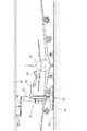
図1〜図4の夫々は、建屋内で航空機Wの機体外面に対して表面処理作業を実施している状況を示している。この表面処理作業では、洗浄処理、塗膜剥がし処理、塗装下地処理、研磨処理、塗装処理、検査処理などの複数種の表面処理を、航空機Wの機体外面に対して順次に施す。 Each of FIGS. 1 to 4 illustrates a situation in which a surface treatment operation is being performed on the exterior surface of the aircraft W in the building. In this surface treatment operation, a plurality of types of surface treatments such as a cleaning treatment, a coating film peeling treatment, a coating base treatment, a polishing treatment, a coating treatment, and an inspection treatment are sequentially applied to the outer surface of the aircraft W.
処理対象の航空機Wを収容した建屋内には、高所作業機1及び低所作業機2を配備してあり、これら作業機1,2の夫々には、多関節式の作業アーム3a,4aを備える旋回動作可能な作業ロボット3,4を装備してある。 An
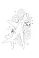
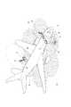
図1,図2は処理対象が大型の航空機Wである場合を示し、図3,図4は処理対象が比較的小型な航空機Wである場合を示している。いずれの場合も、航空機Wにおける高所部分(例えば、胴部上側、翼部上側、垂直尾翼など)に対する処理作業を高所作業機1により実施し、これに並行して、同航空機Wにおける低所部分(例えば、胴部下側、翼部下側など)に対する処理作業を低所作業機2により実施するといった作業分担形態で、高所作業機1及び低所作業機2の両方を用いて航空機Wにおける機体外面の全体を処理する。 1 and 2 show a case where the processing target is a large aircraft W, and FIGS. 3 and 4 show a case where the processing target is a relatively small aircraft W. In any case, the processing work for the high places (for example, the upper fuselage, the upper wing, the vertical tail, etc.) of the aircraft W is performed by the
各作業機1,2は無軌道型の電動式自走台車5,6を備えており、また、各作業機1,2の移動経路を規定するレールや案内ラインなどの施設もなく、その意味で、各作業機1,2は無軌道式の作業機である。
そして、各作業機1,2の自走台車5,6は、車体の向き(即ち、平面視における車体姿勢)の変化を伴わずに水平方向においていずれの向きにも走行することができ、これにより、各作業機1,2は建屋内の床上において任意の位置へ速やかに移動することができる。Each of the working
The self-propelled
また、これら自走台車5,6は、車体の位置の変化を伴うことなく車体の向き(平面視における車体姿勢)を水平方向においていずれの向きにも変更することができ、これにより、各作業機1,2は各位置において、その向きを水平方向における任意の向きに速やかに変更することができる。 In addition, these self-propelled
これら自走台車5,6には、水平方向に対する車体の傾きを調整する傾き調整装置7も装備してあり、この傾き調整装置7を動作させることで、水平方向に対する車体の傾きを水平方向における任意の方向について調整することができる。 The self-propelled
各作業機1,2において、作業ロボット3、4はロボット移動装置Xを介して自走台車5,6上に装備してあり、したがって、自走台車5、6の走行により各作業機1,2を航空機Wの近傍の作業位置に移動させた後、ロボット移動装置Xを動作させることで、作業ロボット3,4を、航空機Wの目標箇所に対する作業が可能となる位置(即ち、作業アーム3a,4aの先端部に保持させた処理機8により航空機Wの機体表面における目標部分を処理できる位置)に移動させることができる。 In each of the
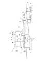
図5及び図6に示すように、高所作業機1には、ロボット移動装置Xとして、自走台車5の台上に設置した伸縮タワー式の昇降装置9と、その昇降装置9における伸縮タワー部9aの上端の昇降台9bに装備した伸縮アーム式の迫り出し装置10とを設けてあり、作業ロボット3は、迫り出し装置10における伸縮アーム10aの先端部に設けた迫り出し台10bに搭載してある。 As shown in FIG. 5 and FIG. 6, as the robot moving device X, a telescopic tower
昇降装置9は、伸縮タワー部9aを図6に示す最大伸長状態まで上向きに伸長動作させることで、大型航空機Wにおける垂直尾翼の上端部に対する作業が可能になる高さまで作業ロボット3を上昇させることができる。 The elevating
また、迫り出し装置10は、伸縮アーム10aを同図6に示す最大伸長状態まで水平向きに伸長動作させることで、大型航空機Wの胴部上側部分における横幅方向中央部に対する作業が可能になる位置まで作業ロボット3を水平方向に迫り出させることができる。 In addition, the squeezing
これら昇降装置9及び迫り出し装置10は、いずれもサーボモータによりラックピニオン機構やボールねじ機構などの伝動機構を介して伸縮タワー部9aや伸縮アーム10aを伸縮動作させる構造にしてあり、それらサーボモータを操作して伸縮タワー部9aや伸縮アーム10aの伸長量を調整することで、航空機Wに対する作業ロボット3の位置を航空機Wの機体形状に応じて調整することができる。 Each of the elevating
図7及び図8に示すように、低所作業機2には、ロボット移動装置Xとして、自走台車6の台上に伸縮ブーム式の昇降装置11を装備し、作業ロボット4は、昇降装置11における伸縮ブーム11aの先端部に設けた昇降台11bに搭載してある。 As shown in FIGS. 7 and 8, the low-
この昇降装置11も、サーボモータによりラックピニオン機構やボールねじ機構などの伝動機構を介して伸縮ブーム11aを伸縮動作させる構造にしてあり、そのサーボモータを操作して伸縮ブーム11aの伸長量を調整することで、航空機Wに対する作業ロボット4の位置を航空機Wの機体形状に応じて調整することができる。
なお、各昇降装置9,11や迫り出し装置10の伝動機構としては、ラックピニオン機構やボールねじ機構に限らず、その他の種々の方式の伝動機構を採用することができる。This elevating
It should be noted that the transmission mechanism of each of the lifting and lowering
各自走台車5,6には、電源接続部12を設けるとともにバッテリー13を搭載してあり、自走台車5,6、並びに、自走台車5,6に装備した作業ロボット3,4、昇降装置9,11,迫り出し装置10などの各電動装置は、電源接続部12に接続した電源線からの供給電力あるいはバッテリー13からの供給電力のいずれによっても動作させることができる。 Each of the self-propelled
作業ロボット3,4における作業アーム3a,4bの先端部(即ち、手首部)に保持させる処理機8は、実施する表面処理の種別に応じて交換することができ、交換用の複数種の処理機8(例えば、薬剤塗布機、洗浄水塗布機、パテ研ぎ機、塗装機など)は、作業ロボット3,4と処理機交換装置との相互動作により自動的に交換できる状態にして各作業機1,2の処理機収容部14に収容してある。 The
また、各作業機1,2には、圧縮空気を使用する処理作業において作業ロボット3,4が保持する処理機8に圧縮空気を供給するコンプレッサーや、塗装処理において作業ロボット3,4が保持する処理機8(塗装機)に塗料及び硬化液を供給するタンク及びポンプなどの各種の供給源装置Yも搭載してある。
なお、各作業機1,2に装備する種々の電動装置については、例えば塗装処理の際の発火トラブルなどを確実に防止するために防爆仕様を採用してある。Each of the working
Note that various electric devices provided in each of the working
一方、各作業機1,2には(図17参照)、周辺物との間の距離を計測するレーザー式の移動用距離センサS1を、作業機1,2における各部(例えば、自走台車5,6の四隅部、迫り出し装置10の迫り出し台10b、伸縮ブーム式昇降装置11の昇降台11bなど)に装備するとともに、自走台車5,6の水平度を計測する水平度センサS2を装備してある。 On the other hand, each of the working
また、各作業機1,2における作業ロボット3,4の作業アーム3a,4aには、航空機Wの機体外面に対する距離を計測するレーザー式の処理用距離センサS3、及び、航空機Wの機体外面における突起物を検出するレーザー式の突起物センサS4などを装備してある。 The working
そして、各作業機1,2には、自走台車5,6並びに作業ロボット3,4などの各搭載装置を制御する車載制御器15を装備してある。 Each of the working
これに対し、処理対象の航空機Wを収容する建屋には、収容した航空機Wの周辺エリアを撮影する複数の位置計測用カメラC1,C2を各部に分散させて設置するとともに、統括制御器16を設置してある。 On the other hand, in the building accommodating the aircraft W to be processed, a plurality of position measurement cameras C1 and C2 for photographing the peripheral area of the accommodated aircraft W are separately installed in each part, and the
各作業機1,2に装備した車載制御器15及び建屋内に設置した統括制御器16は、両作業機1,2を備える表面処理システムの制御を司る制御装置である。 The in-
次に、これら高所作業機1及び低所作業機2を用いて実施する表面処理作業の作業方式について図9〜図17を参照しながら説明するが、この作業方式については、いずれの作業機1,2についてもほぼ同じであることから、ここでは、代表として高所作業機1の方を主にして説明する。 Next, a working method of a surface treatment work performed using the high working
<第1工程>
図9に示すように、建屋内に収容した航空機Wの周囲に複数の作業エリアAを設定しておく。ここで、個々の作業エリアAは、位置計測用カメラC1による撮影が可能な範囲に対応した広さを有する。<First step>
As shown in FIG. 9, a plurality of work areas A are set around an aircraft W housed in a building. Here, each work area A has a size corresponding to a range in which an image can be captured by the position measuring camera C1.
また、収容した航空機Wの機体外面には、その機体外面を複数の区画に細分する状態で行列配置の複数の処理区画Kを設定する。なお、これら処理区画Kの設定は、航空機Wの設計資料などから得る航空機Wの3次元形状データDwに基づいて統括制御器16により自動的に行うようにしてもよい。
<第2工程>
図9〜図10に示すように、統括制御器16ないし車載制御器15に対する手動操作により、作業機1を作業エリアA外の待機位置からいずれかの作業エリアAのエリア内に移動させる。Further, a plurality of processing sections K in a matrix arrangement are set on the outer surface of the body of the accommodated aircraft W in a state where the outer surface of the body is subdivided into a plurality of sections. The setting of the processing section K may be automatically performed by the
<Second step>
As shown in FIGS. 9 and 10, the work implement 1 is moved from a standby position outside the work area A to one of the work areas A by a manual operation on the
この移動操作において、統括制御器16ないし車載制御器15に対する手動操作は、遠隔操作器を用いる遠隔手動操作あるいは統括制御器16や車載制御器15に対する直接的な操作のいずれであってもよい。 In this moving operation, the manual operation on the
また、この作業エリアA内への移動では、電源接続部12を用いずバッテリー13からの供給電力により作業機1の自走台車5を走行させる。 Further, in the movement into the work area A, the self-propelled
作業機1を作業エリアA内に移動させた後は、それに続く作業用電力の確保として、作業機1の電源接続部12に最寄りの電源部から引き出した電源線を接続する。 After the
<第3工程>
この電源接続の後、統括制御器16に予め入力してある航空機Wの3次元形状データDwと、所要位置に設置した位置計測用カメラC1から総括制御器16に無線送信される撮影データDc(即ち、航空機Wの一部と作業機1とが存在する作業エリアAの撮影データ)とに基づいて、作業機1と航空機Wとの相対的な位置関係を統括制御器16に認識させる。<Third step>
After this power connection, the three-dimensional shape data Dw of the aircraft W which has been input to the
そして、認識させた作業機1と航空機Wとの相対的な位置関係に基づいて、作業機1を航空機Wの近傍の指定作業位置Pへ移動させる移動指令を、統括制御器16から作業機1の車載制御器15に無線送信させる。 Then, based on the recognized relative positional relationship between the
この移動指令を受けて、作業機1の車載制御器15は自走台車5を制御することで、図10〜図11に示すように、作業機1を航空機Wの近傍の指定作業位置Pへ自動的に移動させ、また、それに伴い作業機1の向きを航空機Wに正対する作業向きに自動的に調整する。 In response to the movement command, the on-
この指定作業位置Pへの自動移動において、車載制御器15は、作業機1に装備した移動用距離センサS1の計測情報に基づいて作業機1と航空機Wとの間の距離を併行して監視し、この監視により、航空機Wの3次元形状データDwと位置計測用カメラC1による撮影データDcとに基づく自走台車5の制御に補正を加えることで、作業機1を指定作業位置Pに精度良く停止させる。 In the automatic movement to the designated work position P, the on-
また、車載制御器15は、作業機1に装備した移動用距離センサS1の計測情報に基づいて作業機1の周囲における障害物の存否を監視し、障害物の存在が検知されたときには自走台車5を停止させることで障害物との衝突を回避するとともに、障害物の存在を報知する警報を発する。 The in-
さらに、車載制御器15は、作業機1を指定作業位置Pに停止させた後、水平度センサS2の検出情報に基づき傾き調整装置7を制御することで、自走台車5をほぼ完全な水平姿勢に調整する。 Further, after stopping the work implement 1 at the designated work position P, the in-
<第4工程>
自走台車5の水平度を調整した後、車載制御器15は、統括制御器16から送信される航空機Wの3次元形状データDwと、迫り出し台10に装備した移動用距離センサS1により得られる航空機Wの機体との間の距離情報とに基づいて、図12〜図14に示すように、昇降装置9の昇降タワー部9aを伸長動作させて作業ロボット3を所要高さに上昇させるとともに、それに続き、迫り出し装置10の伸縮アーム10aを伸長動作させて、作業ロボット3を航空機Wの機体外面に近付ける。<Fourth step>
After adjusting the level of the self-propelled
即ち、これら昇降装置9及び迫り出し装置10の動作により、作業機1における作業ロボット3を航空機Wの機体外面に設定された処理区画Kのうちの1つに接近させる。 That is, the operation of the
<第5工程>
その後、車載制御器15は、航空機Wの3次元形状データDwと、作業ロボット3の作業アーム3aに装備した処理用距離センサS3により得られる航空機Wの機体外面に対する距離情報とに基づいて、作業ロボット3のアーム動作を制御することで、作業アーム3aに保持させた処理機8を航空機Wの機体外面に対して処理作用させながら処理区画K内を機体外面に沿って移動させ、これにより、航空機Wの機体外面における1つの処理区画Kを処理する。<Fifth step>
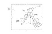
Thereafter, the in-
また、このロボット動作による処理機8の移動において、車載制御器15は、作業アーム3aに装備した処理用距離センサS3により、図15に示すように、処理機8の周りにおける機体外面上の数個の計測点GについてセンサS3と計測点Gとの間の距離を計測し、その計測結果に基づいて、処理機8が処理する機体外面部分の傾きを演算する。 In addition, when the
そして、車載制御器15は、その演算結果に基づいて、航空機Wの3次元形状データDwに基づく処理機8の姿勢制御に補正を加えることで、処理機8を機体外面の各処理部分に対して常に垂直姿勢を保った状態で処理作用させる。 Then, the on-
さらに、車載制御器15は、ロボット動作による処理機8の移動において、図16に示すように、作業アーム3aに装備した突起物センサS4により航空機Wの突起物Tが検出されると、その突起物に対し処理機8を迂回させて移動させるように作業ロボット3を制御する機能も備えている。 Further, as shown in FIG. 16, when the protrusion T of the aircraft W is detected by the protrusion sensor S4 provided on the
<第6工程>
この第5工程により航空機W1の機体外面における1つの処理区画Kに対する処理が終了すると、車載制御器15は、再び航空機Wの3次元形状データDwと迫り出し台10に装備した移動用距離センサS1により得られる航空機Wの機体との間の距離情報とに基づいて昇降装置9及び迫り出し装置10を動作させることで、作業ロボット3を航空機Wの機体外面における次の処理区画Kに接近させる。<Sixth step>
When the processing for one processing section K on the outer surface of the aircraft W1 is completed in the fifth step, the in-
そして、その処理区画Kに対して上記の第5工程を再び実施することで、航空機Wの機体外面における次の1つの処理区画Kを処理する。 Then, by performing the fifth step again on the processing section K, the next processing section K on the outer surface of the aircraft W is processed.
<第7工程>
これら第5工程及び第6工程を繰り返すことで、作業機1を1つの指定停止位置Pに位置させた状態での各処理区画Kに対する処理作業が完了すると、車載制御器15は昇降装置9の伸縮タワー部9a及び迫り出し装置10の伸縮アーム10aを収縮動作させて作業ロボット3を作業機1における格納位置に戻す。<Seventh step>
By repeating the fifth step and the sixth step, when the processing operation for each processing section K in a state where the work implement 1 is located at one designated stop position P is completed, the on-
その後、統括作業器16は、認識している作業機1と航空機Wとの相対的な位置関係に基づいて、作業器1を同じ作業エリアA内における航空機Wの近傍の次の指定作業位置P′に移動させる移動指令を車載制御器15に発信し、この移動指令に応答して、車載制御器15は、前記した第3工程と同様にして、作業機1を次の指定作業位置P′に移動させる。 Thereafter, based on the recognized relative positional relationship between the work implement 1 and the aircraft W, the overall work implement 16 moves the work implement 1 to the next designated work position P near the aircraft W in the same work area A. ′ Is transmitted to the on-
また、車載制御器15は、その指定作業位置P′において改めて水平度センサS2の検出情報に基づき傾き調整装置7を制御することで、自走台車5を再度、水平姿勢に調整し、その後、第4工程〜第7工程を繰り返すことで、1つの作業エリアAでの処理作業を完了する。 Further, the on-
そして、1つの作業エリアAでの処理作業を完了すると、残りの作業エリアAの夫々において同様に第1工程〜第7工程の順で処理作業を進め、これにより、複数種の表面処理作業のうちの一種の処理作業を航空機Wの機体外面の全体に対して施し、それを終了すると、作業ロボット3の作業アーム3aに保持させる処理機8を交換した上で、同様に各作業エリアAごとに航空機Wの機体外面に対する表面処理作業を進める。 When the processing work in one work area A is completed, the processing work is similarly performed in each of the remaining work areas A in the order of the first step to the seventh step. When one type of processing work is performed on the entire outer surface of the aircraft body of the aircraft W and the processing is completed, the
航空機Wの機体外面に対する以上の一連の表面処理作業において、低所作業機2は、迫り出し装置10に対する制御を除いて高所作業機1と同様に制御する。
なお、高所作業機1と低所作業機2とは、基本的に一対で用いられ、処理対象物体Wを挟んだ両側の相対する位置に配置するなどして相互に作業領域が干渉しないような状態で制御される。In the above series of surface treatment operations on the outer surface of the body of the aircraft W, the
Note that the
本発明は、航空機に限らず、鉄道車両、船舶、ロケットあるいは橋梁や住居など種々の大型物体の表面処理に利用することができる。 INDUSTRIAL APPLICABILITY The present invention is not limited to aircraft, and can be used for surface treatment of various large objects such as railway vehicles, ships, rockets, bridges and houses.
W 航空機(処理対象物体)
8 処理機
3,4 作業ロボット
3a,4a 作業アーム
5,6 自走台車
1,2 無軌道式の作業機
X ロボット移動装置(昇降装置、迫り出し装置)
15 車載制御器(制御装置)
16 統括制御器(制御装置)
A 作業エリア
C1、C2 位置計測用カメラ
Dc 撮影データ
P,P′ 指定作業位置
Dw 3次元形状データ
S1 移動用距離センサ
S2 水平度センサ
7 傾き調整装置
S3 処理用距離センサ
S4 突起物センサ
T 突起物
K 処理区画
G 計測点W aircraft (objects to be processed)
15 In-vehicle controller (control device)
16 General controller (control device)
A Work area C1, C2 Position measurement camera Dc Photographing data P, P 'Designated work position Dw Three-dimensional shape data S1 Moving distance sensor
Claims (9)
Translated fromJapanese前記作業ロボットの動作により前記処理機を前記物体の表面に対して移動させながら、前記処理機により前記物体の表面を処理するのに、
自走台車に前記作業ロボットを搭載した無軌道式の作業機を設け、
前記作業機には、前記作業ロボットを前記自走台車に対して少なくとも高さ方向に移動させるロボット移動装置を装備し、
前記自走台車、前記ロボット移動装置、前記作業ロボットの夫々を制御装置により制御する表面処理システムの制御方法であって、
前記物体と前記作業機とが存在する作業エリアを位置計測用カメラにより撮影し、
前記制御装置は、前記位置計測用カメラの撮影データと、入力された前記物体の3次元形状データとに基づき前記物体と前記作業機との相対的な位置関係を認識して、
認識した前記相対的な位置関係に基づいて前記自走台車を制御することで、前記作業機を前記物体の近傍の指定作業位置に移動させる表面処理システムの制御方法。A processing machine for processing the surface of the object is held at the tip of the working arm in the working robot,
While processing the surface of the object by the processing machine while moving the processing machine with respect to the surface of the object by the operation of the work robot,
A trackless work machine equipped with the work robot is mounted on a self-propelled carriage,
The work machine is equipped with a robot moving device that moves the work robot at least in a height direction with respect to the self-propelled carriage,
The self-propelled trolley, the robot moving device, a control method of a surface treatment system that controls each of the work robot by a control device,
The work area where the object and the work machine are present is photographed by a position measurement camera,
The control device recognizes the relative positional relationship between the object and the working machine based on the imaging data of the position measurement cameraand the input three-dimensional shape data of the object,
A control method for a surface treatment system that moves the work implement to a designated work position near the object by controlling the self-propelled trolley based on the recognized relative positional relationship.
前記制御装置は、前記作業機の前記指定作業位置への移動において、前記相対的な位置関係と前記移動用距離センサの計測情報とに基づいて前記自走台車を制御する請求項1に記載した表面処理システムの制御方法。In the movement of the work machine to the designated work position, a movement distance sensor mounted on the work machine measures a distance between the object and the object,
2. The control device according to claim 1, wherein the control device controls the self-propelled carriage based on the relative positional relationship and measurement information of the moving distance sensor when the work implement moves to the designated work position. 3. Control method of surface treatment system.
前記制御装置は、前記ロボット移動装置による前記作業ロボットの移動において、前記3次元形状データと前記移動用距離センサの計測情報とに基づいて前記ロボット移動装置
を制御する請求項4に記載した表面処理システムの制御方法。A moving distance sensor that moves together with the work robot by the operation of the robot moving device measures a distance between the object and the object,
The control device is configured to control the robot moving device based on the three-dimensional shape data and the measurement information of the moving distance sensor when the work robot is moved by the robot moving device.
The method for controllinga surface treatment system accordingto claim 4, wherein the control is performed.
前記制御装置は、前記処理機による前記物体の表面処理において、前記3次元形状データと前記処理用距離センサの計測情報とに基づいて前記作業ロボットを制御することで、前記処理機を前記物体の表面に対して移動させる請求項6に記載した表面処理システムの制御方法。In the surface treatment of the object by the processing machine, a processing distance sensor equipped on the work arm measures a distance to a surface of the object,
The control device controls the work robot based on the three-dimensional shape data and the measurement information of the processing distance sensor in the surface processing of the object by the processing machine, thereby causing the processing machine to process the object. The control methodfor a surface treatment system accordingto claim 6, wherein the movement is performed with respect to the surface.
前記制御装置は、前記処理機による前記物体の表面処理において、前記突起物センサの検出情報に基づいて前記作業ロボットを制御することで、前記処理機を前記突起物に対して迂回移動させる請求項1〜7のいずれか1項に記載した表面処理システムの制御方法。In the surface treatment of the object by the processing machine, a protrusion sensor equipped on the work arm detects the presence or absence of a protrusion on the object,
The control device controls the work robot based on detection information of the projection sensor in the surface treatment of the object by the processing machine, thereby causing the processing machine to detour with respect to the projection. A method for controllinga surface treatment system accordingto any one of claims 1 to 7 .
前記制御装置は、前記処理機のよる前記物体の表面処理において、前記処理用距離センサの計測情報に基づいて前記作業ロボットを制御することで、前記物体の表面に対する前記処理機の姿勢を調整する請求項1〜8のいずれか1項に記載した表面処理システムの制御方法。In the surface treatment of the object by the processing machine, a processing distance sensor equipped on the work arm measures a distance to each of a plurality of measurement points on the surface of the object,
The control device adjusts a posture of the processing machine with respect to a surface of the object by controlling the work robot based on measurement information of the processing distance sensor in the surface processing of the object by the processing machine. A method for controllinga surface treatment system accordingto claim 1 .
Priority Applications (6)
| Application Number | Priority Date | Filing Date | Title |
|---|---|---|---|
| JP2017233713AJP6678155B2 (en) | 2017-12-05 | 2017-12-05 | Control method of surface treatment system |
| MX2019013513AMX387064B (en) | 2017-12-05 | 2018-10-09 | Method for controlling surface processing system |
| PCT/JP2018/037571WO2019111523A1 (en) | 2017-12-05 | 2018-10-09 | Method for controlling surface processing system |
| CN201880035908.2ACN110709214B (en) | 2017-12-05 | 2018-10-09 | Control method of surface treatment system |
| US16/615,244US20200198154A1 (en) | 2017-12-05 | 2018-10-09 | Method of Controlling Surface Treatment System |
| TW107136879ATWI724335B (en) | 2017-12-05 | 2018-10-19 | Control method for surface treatment system |
Applications Claiming Priority (1)
| Application Number | Priority Date | Filing Date | Title |
|---|---|---|---|
| JP2017233713AJP6678155B2 (en) | 2017-12-05 | 2017-12-05 | Control method of surface treatment system |
Publications (2)
| Publication Number | Publication Date |
|---|---|
| JP2019098483A JP2019098483A (en) | 2019-06-24 |
| JP6678155B2true JP6678155B2 (en) | 2020-04-08 |
Family
ID=66750942
Family Applications (1)
| Application Number | Title | Priority Date | Filing Date |
|---|---|---|---|
| JP2017233713AActiveJP6678155B2 (en) | 2017-12-05 | 2017-12-05 | Control method of surface treatment system |
Country Status (6)
| Country | Link |
|---|---|
| US (1) | US20200198154A1 (en) |
| JP (1) | JP6678155B2 (en) |
| CN (1) | CN110709214B (en) |
| MX (1) | MX387064B (en) |
| TW (1) | TWI724335B (en) |
| WO (1) | WO2019111523A1 (en) |
Cited By (1)
| Publication number | Priority date | Publication date | Assignee | Title |
|---|---|---|---|---|
| WO2023057932A1 (en)* | 2021-10-07 | 2023-04-13 | Target Robotics Institute, S.A. De C.V. | Robotised vehicle washing system |
Families Citing this family (10)
| Publication number | Priority date | Publication date | Assignee | Title |
|---|---|---|---|---|
| US10829354B2 (en)* | 2017-12-20 | 2020-11-10 | Cti Systems S.a.r.l. | Collision avoidance assistance system for movable work platforms |
| JP6681567B1 (en)* | 2019-05-27 | 2020-04-15 | 千住金属工業株式会社 | Solder paste and flux |
| ES1243504Y (en)* | 2020-02-13 | 2020-09-01 | Sosa Gonzalez S L | Autonomous painting robot |
| JP7426858B2 (en)* | 2020-03-10 | 2024-02-02 | 株式会社大気社 | Inspection equipment and inspection method |
| CN113021366B (en)* | 2021-02-25 | 2022-03-25 | 深圳市润安科技发展有限公司 | Video information acquisition robot |
| CN113135300B (en)* | 2021-04-14 | 2022-09-02 | 中国航空规划设计研究总院有限公司 | Automatic planning control system for aircraft surface treatment and use method thereof |
| GB2625725A (en)* | 2022-12-21 | 2024-07-03 | Univ Sheffield | Mobile robot |
| CN116160434B (en)* | 2023-04-24 | 2023-07-14 | 南京智欧智能技术研究院有限公司 | Wire-controlled robot with combined operating space and working method |
| FR3150129A1 (en)* | 2023-06-26 | 2024-12-27 | Airbus (S.A.S.) | Painting device comprising a mobile robotic arm supporting a tool and mobile equipment connected by an umbilical link to the tool |
| CN118341602B (en)* | 2024-06-11 | 2024-08-23 | 成都裕鸢航空智能制造股份有限公司 | Spraying device and spraying process for aircraft wing |
Family Cites Families (13)
| Publication number | Priority date | Publication date | Assignee | Title |
|---|---|---|---|---|
| JP3583450B2 (en)* | 1993-09-28 | 2004-11-04 | 川崎重工業株式会社 | Automatic three-dimensional object inspection apparatus and method |
| JPH10264060A (en)* | 1997-03-27 | 1998-10-06 | Trinity Ind Corp | Teaching device of painting robot |
| US6873880B2 (en)* | 2001-12-26 | 2005-03-29 | Lockheed Martin Corporation | Machine for performing machining operations on a workpiece and method of controlling same |
| US9102055B1 (en)* | 2013-03-15 | 2015-08-11 | Industrial Perception, Inc. | Detection and reconstruction of an environment to facilitate robotic interaction with the environment |
| US10201847B2 (en)* | 2014-07-09 | 2019-02-12 | The Boeing Company | Clamping feet for an end effector |
| WO2016067467A1 (en)* | 2014-10-31 | 2016-05-06 | 三菱電機株式会社 | Robot control device, robot system, robot control method, and program |
| US10059004B2 (en)* | 2015-06-22 | 2018-08-28 | Ricoh Company, Ltd. | Robot, information processing system, and storage medium |
| US9972215B2 (en)* | 2015-08-18 | 2018-05-15 | Lincoln Global, Inc. | Augmented reality interface for weld sequencing |
| JP2017039188A (en)* | 2015-08-20 | 2017-02-23 | 株式会社東芝 | Mobile robot and construction position confirmation method |
| EP3135442B1 (en)* | 2015-08-26 | 2018-12-19 | Airbus Operations GmbH | Robot system and method of operating a robot system |
| CN105107654B (en)* | 2015-08-27 | 2018-02-23 | 哈尔滨商业大学 | A kind of robot continous way automatic paint spraying apparatus towards large-scale workpiece |
| JP6713762B2 (en)* | 2015-12-18 | 2020-06-24 | 清水建設株式会社 | Construction work robot and method for controlling construction work robot |
| WO2018183937A1 (en)* | 2017-03-31 | 2018-10-04 | Canvas Construction, Inc. | Automated insulation application system and method |
- 2017
- 2017-12-05JPJP2017233713Apatent/JP6678155B2/enactiveActive
- 2018
- 2018-10-09CNCN201880035908.2Apatent/CN110709214B/enactiveActive
- 2018-10-09WOPCT/JP2018/037571patent/WO2019111523A1/ennot_activeCeased
- 2018-10-09MXMX2019013513Apatent/MX387064B/enunknown
- 2018-10-09USUS16/615,244patent/US20200198154A1/ennot_activeAbandoned
- 2018-10-19TWTW107136879Apatent/TWI724335B/enactive
Cited By (1)
| Publication number | Priority date | Publication date | Assignee | Title |
|---|---|---|---|---|
| WO2023057932A1 (en)* | 2021-10-07 | 2023-04-13 | Target Robotics Institute, S.A. De C.V. | Robotised vehicle washing system |
Also Published As
| Publication number | Publication date |
|---|---|
| CN110709214B (en) | 2022-10-14 |
| TWI724335B (en) | 2021-04-11 |
| US20200198154A1 (en) | 2020-06-25 |
| JP2019098483A (en) | 2019-06-24 |
| MX2019013513A (en) | 2020-01-20 |
| TW201924882A (en) | 2019-07-01 |
| WO2019111523A1 (en) | 2019-06-13 |
| MX387064B (en) | 2025-03-19 |
| CN110709214A (en) | 2020-01-17 |
Similar Documents
| Publication | Publication Date | Title |
|---|---|---|
| JP6678155B2 (en) | Control method of surface treatment system | |
| JP6678154B2 (en) | Surface treatment system for large objects | |
| TWI802465B (en) | Automated system for spraying wall of building | |
| US10875666B2 (en) | Passenger boarding bridge | |
| JP6713762B2 (en) | Construction work robot and method for controlling construction work robot | |
| CN104723318A (en) | Autonomous working robot system | |
| US12053880B2 (en) | Mobile robot platform | |
| KR100751702B1 (en) | Mobile hull shell automatic painting system with scissor type lift and lower lift | |
| KR20150026461A (en) | Cable robot system | |
| US10391412B2 (en) | Amusement ride with robot system | |
| WO2022208655A1 (en) | Passenger boarding bridge | |
| JP7449448B2 (en) | passenger boarding bridge | |
| US12360538B1 (en) | Operations of articulating boom assemblies | |
| HK40077133A (en) | Automated system for spraying wall of building | |
| JPH0348160Y2 (en) | ||
| KR20150140174A (en) | Cargo hold maintenance system and method using robot | |
| HK40003852A (en) | Automated system for spraying wall of building | |
| JP2023057410A (en) | Conveying system and method | |
| WO2020156560A1 (en) | Climbing tower crane apparatus and control method therefor, traveling crane system and fault handling method and control method therefor |
Legal Events
| Date | Code | Title | Description |
|---|---|---|---|
| A621 | Written request for application examination | Free format text:JAPANESE INTERMEDIATE CODE: A621 Effective date:20190201 | |
| A131 | Notification of reasons for refusal | Free format text:JAPANESE INTERMEDIATE CODE: A131 Effective date:20190910 | |
| A521 | Request for written amendment filed | Free format text:JAPANESE INTERMEDIATE CODE: A523 Effective date:20191015 | |
| TRDD | Decision of grant or rejection written | ||
| A01 | Written decision to grant a patent or to grant a registration (utility model) | Free format text:JAPANESE INTERMEDIATE CODE: A01 Effective date:20200303 | |
| A61 | First payment of annual fees (during grant procedure) | Free format text:JAPANESE INTERMEDIATE CODE: A61 Effective date:20200316 | |
| R150 | Certificate of patent or registration of utility model | Ref document number:6678155 Country of ref document:JP Free format text:JAPANESE INTERMEDIATE CODE: R150 | |
| R250 | Receipt of annual fees | Free format text:JAPANESE INTERMEDIATE CODE: R250 | |
| R250 | Receipt of annual fees | Free format text:JAPANESE INTERMEDIATE CODE: R250 | |
| R250 | Receipt of annual fees | Free format text:JAPANESE INTERMEDIATE CODE: R250 |