JP6675984B2 - Image processing apparatus, image processing method, and program - Google Patents
Image processing apparatus, image processing method, and programDownload PDFInfo
- Publication number
- JP6675984B2 JP6675984B2JP2016540146AJP2016540146AJP6675984B2JP 6675984 B2JP6675984 B2JP 6675984B2JP 2016540146 AJP2016540146 AJP 2016540146AJP 2016540146 AJP2016540146 AJP 2016540146AJP 6675984 B2JP6675984 B2JP 6675984B2
- Authority
- JP
- Japan
- Prior art keywords
- current frame
- region
- head
- information
- image
- Prior art date
- Legal status (The legal status is an assumption and is not a legal conclusion. Google has not performed a legal analysis and makes no representation as to the accuracy of the status listed.)
- Expired - Fee Related
Links
Images


Classifications
- H—ELECTRICITY
- H04—ELECTRIC COMMUNICATION TECHNIQUE
- H04N—PICTORIAL COMMUNICATION, e.g. TELEVISION
- H04N7/00—Television systems
- H04N7/18—Closed-circuit television [CCTV] systems, i.e. systems in which the video signal is not broadcast
- G—PHYSICS
- G06—COMPUTING OR CALCULATING; COUNTING
- G06T—IMAGE DATA PROCESSING OR GENERATION, IN GENERAL
- G06T7/00—Image analysis
- G06T7/20—Analysis of motion
- G06T7/246—Analysis of motion using feature-based methods, e.g. the tracking of corners or segments
- G—PHYSICS
- G06—COMPUTING OR CALCULATING; COUNTING
- G06T—IMAGE DATA PROCESSING OR GENERATION, IN GENERAL
- G06T7/00—Image analysis
- G06T7/20—Analysis of motion
- G06T7/254—Analysis of motion involving subtraction of images
- G—PHYSICS
- G06—COMPUTING OR CALCULATING; COUNTING
- G06T—IMAGE DATA PROCESSING OR GENERATION, IN GENERAL
- G06T7/00—Image analysis
- G06T7/90—Determination of colour characteristics
- G—PHYSICS
- G06—COMPUTING OR CALCULATING; COUNTING
- G06V—IMAGE OR VIDEO RECOGNITION OR UNDERSTANDING
- G06V20/00—Scenes; Scene-specific elements
- G06V20/50—Context or environment of the image
- G06V20/52—Surveillance or monitoring of activities, e.g. for recognising suspicious objects
- G—PHYSICS
- G06—COMPUTING OR CALCULATING; COUNTING
- G06V—IMAGE OR VIDEO RECOGNITION OR UNDERSTANDING
- G06V40/00—Recognition of biometric, human-related or animal-related patterns in image or video data
- G06V40/10—Human or animal bodies, e.g. vehicle occupants or pedestrians; Body parts, e.g. hands
- G06V40/16—Human faces, e.g. facial parts, sketches or expressions
- G06V40/161—Detection; Localisation; Normalisation
- G—PHYSICS
- G06—COMPUTING OR CALCULATING; COUNTING
- G06T—IMAGE DATA PROCESSING OR GENERATION, IN GENERAL
- G06T2207/00—Indexing scheme for image analysis or image enhancement
- G06T2207/10—Image acquisition modality
- G06T2207/10024—Color image
- G—PHYSICS
- G06—COMPUTING OR CALCULATING; COUNTING
- G06T—IMAGE DATA PROCESSING OR GENERATION, IN GENERAL
- G06T2207/00—Indexing scheme for image analysis or image enhancement
- G06T2207/30—Subject of image; Context of image processing
- G06T2207/30196—Human being; Person
- G—PHYSICS
- G06—COMPUTING OR CALCULATING; COUNTING
- G06T—IMAGE DATA PROCESSING OR GENERATION, IN GENERAL
- G06T2207/00—Indexing scheme for image analysis or image enhancement
- G06T2207/30—Subject of image; Context of image processing
- G06T2207/30236—Traffic on road, railway or crossing
Landscapes
- Engineering & Computer Science (AREA)
- Multimedia (AREA)
- Physics & Mathematics (AREA)
- General Physics & Mathematics (AREA)
- Theoretical Computer Science (AREA)
- Computer Vision & Pattern Recognition (AREA)
- Signal Processing (AREA)
- Health & Medical Sciences (AREA)
- General Health & Medical Sciences (AREA)
- Oral & Maxillofacial Surgery (AREA)
- Human Computer Interaction (AREA)
- Image Analysis (AREA)
- Closed-Circuit Television Systems (AREA)
- Image Processing (AREA)
Description
Translated fromJapanese本開示は、画像処理装置、画像処理方法、およびプログラムに関し、特に、例えば、動画像上に出現する物体を追尾する場合に用いて好適な画像処理装置、画像処理方法、およびプログラムに関する。 The present disclosure relates to an image processing device, an image processing method, and a program, and more particularly, to an image processing device, an image processing method, and a program suitable for, for example, tracking an object appearing on a moving image.
従来、動画像上に出現する物体を検出する技術は存在し、動きがある物体(以下、動物体と称する)はもちろん、画像上で止まっている物体(以下、静止物体と称する)も検出することができる。 2. Description of the Related Art Conventionally, there is a technique for detecting an object appearing on a moving image, and detects not only a moving object (hereinafter, referred to as a moving object) but also an object that is stopped on an image (hereinafter, referred to as a still object). be able to.
例えば、特許文献1には、短期間の動画像に基づいて生成した短期背景画像と入力画像の差分のみを用いて物体の位置を算出する。そして、その動物体がある一定時間停止した場合、長期間の動画像に基づいて生成した長期背景画像と入力画像の差分を用いて、その停止している物体の位置の算出する発明が記載されている。 For example, in
特許文献1の発明では、短期背景画像を用いることで動物体や短期間だけ停止している静止物体を検出することができ、それとは独立して、長期背景画像を用いることで長期間停止している静止物体を検出することができる。ただし、動物体と静止物体は独立して検出されるので、検出された動物体と静止物体が同一の物体であるか否かについては確認できない。よって、例えば、動きのある物体が画像上で停止し、長期間経過後に再び動き出したような場合、それらを同一の物体として検出し、追尾することはできない。 According to the invention of
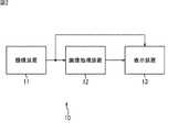
図1は、上記問題を具体的に説明するためのものであり、動画像上で検出された物体(同物体および静止物体)と、それに付与されるIDを示していて、縦方向に時間が経過しているものとする。 FIG. 1 is for specifically explaining the above problem, and shows objects detected on a moving image (the same object and a stationary object) and IDs assigned to the objects. It has passed.
同図の左側の列に示すように、特許文献1の発明では、時刻t1,t2のフレーム上を移動する自動車を動物体として検出することができ、それに同一のID:8を付与することができる。ただし、時刻t3からt4にかけてフレーム上で自動車が停止すると、それは静止物体として検出されてID:100が付与される。 As shown in the left column of the figure, in the invention of
さらに、停止していた自動車が時刻t5からt6にかけて再び動き出すと、該自動車は再び動物体として検出されて、それまでとは異なるID:9が付与れる。さらに、自動車が停止していた跡に対して動物体(ID:10)が誤検出されることも起こり得る。 Further, when the stopped vehicle starts moving again from time t5 to t6, the vehicle is detected again as a moving object, and an ID: 9 different from that before is given. Further, the moving object (ID: 10) may be erroneously detected at the mark where the vehicle has stopped.
上述したように、従来の技術では、動画像上で検出した動物体や静止物体が同一の物体であったとしても、それを同一の物体として処理すること、具体的には、同図の右側の列のように、同一のIDを付与することができない。 As described above, in the related art, even if the moving object or the stationary object detected on the moving image is the same object, it is processed as the same object. Cannot be assigned the same ID as in the column.
本開示はこのような状況に鑑みてなされたものであり、動画像上の物体を継続的に追尾できるようにするものである。 The present disclosure has been made in view of such a situation, and is to enable continuous tracking of an object on a moving image.
本開示の一側面である画像処理装置は、動画像上の物体を検出する画像処理装置において、前記動画像の現フレームから、それぞれが異なる基準に基づいて画像上の物体に関する物体特徴量を計算する複数の物体特徴量計算部と、前記動画像の前フレーム上の物体に関する物体属性情報を利用して、前記異なる基準に基づいて計算された複数の前記物体特徴量の中から利用する物体特徴量を選択する特徴量選択部と、選択された前記特徴量と、前記前フレーム上の物体に関する物体情報としての位置ベクトルを用いて、現フレーム上の物体に関する物体情報としての位置ベクトルを計算する物体情報計算部と、計算された現フレーム上の物体に関する前記物体情報としての前記位置ベクトルに基づき、現フレーム上の物体に関する物体属性情報を計算する物体属性情報計算部とを備える。An image processing device according to an aspect of the present disclosure is an image processing device that detects an object on a moving image, wherein the image processing device calculates an object feature amount of the object on the image based on a different criterion from a current frame of the moving image. A plurality of object feature amounts to be calculated, and an object feature to be used from among the plurality of object feature amounts calculated based on the different criterion, using object attribute information on an object on a previous frame of the moving image. by using the feature quantity selection unit for selecting the amount, and the feature quantities selected, theposition vector of the object information about the object on the front frame, calculates theposition vector of the object information about an object on the current frame based onthe position vector of the object information calculation section,as the object information on the calculated object on the current frame was the object attribute information relating to an object on the current frame Calculating a and a object attribute information calculation unit.
前記複数の物体特徴量計算部は、短期背景画像と前記現フレームとの対応する画素の輝度の差分を第1の物体特徴量として計算する第1の物体特徴量計算部と、長期背景画像と前記現フレームとの対応する画素の輝度の差分を第2の物体特徴量として計算する第2の物体特徴量計算部とを有し、前記特徴量選択部は、前記前フレーム上の物体に関する物体属性情報としての停止カウント値を利用して、画素毎に前記第1または第2の特徴量を選択することにより差分画像を生成し、前記物体位置計算部は、生成された前記差分画像と、前記前フレーム上の物体に関する物体情報としての前記位置ベクトルを用いて、現フレーム上の物体に関する物体情報としての前記位置ベクトルを計算し、前記物体属性情報計算部は、計算された現フレーム上の物体に関する前記物体情報としての前記位置ベクトルに基づき、現フレーム上の物体に関する前記物体属性情報としての前記停止カウント値をカウントすることができる。The plurality of object feature value calculation units are a first object feature value calculation unit that calculates, as a first object feature value, a difference in luminance between pixels corresponding to the short-term background image and the current frame; A second object feature amount calculation unit that calculates a difference in luminance of a pixel corresponding to the current frame as a second object feature amount, wherein the feature amount selection unit includes an object related to an object on the previous frame. Utilizing a stop count value as attribute information, a difference image is generated by selecting the first or second feature amount for each pixel, the object position calculation unit generates the difference image, usingthe position vector of the object information about the object on the previous frame, the current frame and calculatesthe position vector of the object information about the object on the current frame, the object attribute information calculation unit calculated Of based on the position vector as the object information on the object, it is possible to count the stop count value as the object attribute information relating to an object on the current frame.
前記物体位置計算部は、生成された前記差分画像に基づいて現フレーム上の物体候補を検出し、前記前フレーム上の物体にもっとも距離が近い現フレーム上の前記物体候補に対して、前記前フレーム上の前記物体に付与されている物体IDを引き継がせることができる。 The object position calculation unit detects an object candidate on the current frame based on the generated difference image, and, for the object candidate on the current frame closest to the object on the previous frame, the The object ID assigned to the object on the frame can be taken over.
本開示の一側面である画像処理装置は、頭部検出領域を設定する頭部検出領域設定部をさらに備えることができ、前記複数の物体特徴量計算部は、前記現フレームの前記頭部検出領域以外から人の全身領域候補を第1の物体特徴量として計算する第1の物体特徴量計算部と、前記現フレームの前記頭部検出領域から人の頭部領域候補を第2の物体特徴量として計算する第2の物体特徴量計算部とを有し、前記特徴量選択部は、前記前フレームの全身領域および頭部領域を一つずつ注目領域に指定し、前記注目領域の頭部の中心座標が前記頭部検出領域内にあるか否かに応じて、前記現フレームの前記全身領域候補または前記頭部領域候補を選択して、現フレームの全身領域または頭部領域に特定し、前記物体位置計算部は、前記前フレーム上の物体に関する物体情報としての前記注目領域の前記位置ベクトルを用いて、現フレーム上の物体に関する物体情報として、特定された前記全身領域または前記頭部領域の前記位置ベクトルを計算し、前記物体属性情報計算部は、計算された現フレーム上の物体に関する前記物体情報としての前記全身領域または前記頭部領域の前記位置ベクトルに基づき、現フレーム上の物体に関する前記物体属性情報として、前記全身領域の頭部の中心座標または前記頭部領域の中心座標を計算することができる。The image processing device according to an aspect of the present disclosure may further include a head detection region setting unit that sets a head detection region, wherein the plurality of object feature amount calculation units are configured to detect the head of the current frame. A first object feature value calculation unit that calculates a human whole body region candidate from a region other than the region as a first object feature value; and a human head region candidate from the head detection region of the current frame. A second object feature value calculation unit for calculating as a quantity, wherein the feature value selection unit designates the whole body region and the head region of the previous frame one by one as the attention region, and the head of the attention region. Depending on whether or not the center coordinates are within the head detection region, the whole body region candidate or the head region candidate of the current frame is selected and specified as the whole body region or the head region of the current frame. , The object position calculation unit, on the previous frame Usingthe position vector of the region of interest as the object information on the object, as the object information on the object on the current frame, it calculatesthe position vector of the identified the systemic region or the head area, the object attribute information The calculating unit is configured to calculate the head of the whole body region as the object attribute information on the object on the current frame based on the calculated position vector of the whole body region or the head region as the object information on the object on the current frame. The center coordinates of the part or the center coordinates of the head region can be calculated.
前記特徴量選択部は、前記注目領域の頭部の中心座標が前記頭部検出領域内にある場合、前記注目領域に最も距離が近い前記現フレームの前記頭部領域候補を選択して、前記注目領域の物体IDを引き継がせて、現フレームの頭部領域に特定し、前記注目領域の頭部の中心座標が前記頭部検出領域内にない場合、前記注目領域に最も距離が近い前記現フレームの前記全身領域候補を選択して、前記注目領域の物体IDを引き継がせて、現フレームの全身領域に特定することができる。 The feature amount selection unit, when the center coordinates of the head of the attention area is within the head detection area, selects the head area candidate of the current frame closest to the attention area, The object ID of the attention area is taken over and specified in the head area of the current frame, and when the center coordinates of the head of the attention area are not within the head detection area, the current distance closest to the attention area is determined. By selecting the whole body region candidate of the frame, the object ID of the attention region can be taken over, and the whole body region of the current frame can be specified.
本開示の一側面である画像処理方法は、動画像上の物体を検出する画像処理装置の画像処理方法において、前記画像処理装置による、前記動画像の現フレームから、それぞれが異なる基準に基づいて画像上の物体に関する複数の物体特徴量を計算する物体特徴量計算ステップと、前記動画像の前フレーム上の物体に関する物体属性情報を利用して、前記異なる基準に基づいて計算された複数の前記物体特徴量の中から利用する物体特徴量を選択する特徴量選択ステップと、選択された前記特徴量と、前記前フレーム上の物体に関する物体情報としての位置ベクトルを用いて、現フレーム上の物体に関する物体情報としての位置ベクトルを計算する物体情報計算ステップと、計算された現フレーム上の物体に関する前記物体情報としての前記位置ベクトルに基づき、現フレーム上の物体に関する物体属性情報を計算する物体属性情報計算ステップとを含む。An image processing method according to an aspect of the present disclosure is an image processing method for an image processing device that detects an object on a moving image, wherein the image processing device uses the current frame of the moving image based on different criteria. An object feature amount calculating step of calculating a plurality of object feature amounts of an object on the image, and using the object attribute information on the object on the previous frame of the moving image, the plurality of the plurality of calculated on the basis of the different criteria. A feature amount selecting step of selecting an object feature amount to be used from among the object feature amounts; and using the selected feature amount anda position vector as object information relating to the object on the previous frame, an object on the current frame. and the object information calculating step of calculating aposition vector of the object information relating tothe position as the object information on the calculated object on the current frame was Based onthe vector, including the object attribute information calculating step of calculating the object attribute information relating to an object on the current frame.
本開示の一側面であるプログラムは、動画像上の物体を検出するコンピュータを、前記動画像の現フレームから、それぞれが異なる基準に基づいて画像上の物体に関する物体特徴量を計算する複数の物体特徴量計算部と、前記動画像の前フレーム上の物体に関する物体属性情報を利用して、前記異なる基準に基づいて計算された複数の前記物体特徴量の中から利用する物体特徴量を選択する特徴量選択部と、選択された前記特徴量と、前記前フレーム上の物体に関する物体情報としての位置ベクトルを用いて、現フレーム上の物体に関する物体情報としての位置ベクトルを計算する物体情報計算部と、計算された現フレーム上の物体に関する前記物体情報としての前記位置ベクトルに基づき、現フレーム上の物体に関する物体属性情報を計算する物体属性情報計算部として機能させる。A program according to one aspect of the present disclosure is directed to a computer that detects an object on a moving image, from a current frame of the moving image, a plurality of objects that calculate an object feature amount related to the object on the image based on different criteria. Using a feature amount calculation unit and object attribute information on an object on a previous frame of the moving image, an object feature amount to be used is selected from among the plurality of object feature amounts calculated based on the different criteria. A feature amount selecting unit, and an object information calculating unit that calculates aposition vector as object information about an object on the current frame using the selected feature amount anda position vector as object information about the object on the previous frame. If, based onthe position vector as the object information on the calculated object on the current frame was, calculates the object attribute information relating to an object on the current frame That function as the object attribute information calculation unit.
本開示の一側面においては、動画像の現フレームから、それぞれが異なる基準に基づいて画像上の物体に関する複数の物体特徴量が計算され、前記動画像の前フレーム上の物体に関する物体属性情報を利用して、前記異なる基準に基づいて計算された複数の前記物体特徴量の中から利用する物体特徴量が選択され、選択された前記特徴量と、前記前フレーム上の物体に関する物体情報としての位置ベクトルを用いて、現フレーム上の物体に関する物体情報としての位置ベクトルが計算される。さらに、計算された現フレーム上の物体に関する前記物体情報としての前記位置ベクトルに基づき、現フレーム上の物体に関する物体属性情報が計算される。According to an aspect of the present disclosure, a plurality of object feature amounts related to an object on an image are calculated from a current frame of a moving image based on different criteria, and object attribute information about an object on a previous frame of the moving image is calculated. Utilizing, an object feature value to be used is selected from among the plurality of the object feature values calculated based on the different criteria, and the selected feature value and object information relating to the object on the previous frameare used. Using the position vector ,a position vector as object information on the object on the current frame is calculated. Further, object attribute information on the object on the current frame is calculated based on the calculatedposition vector as the object information on the object on the current frame.
本開示の一側面によれば、動画像上の物体を継続的に追尾することができる。 According to an embodiment of the present disclosure, it is possible to continuously track an object on a moving image.
以下、本開示を実施するための最良の形態(以下、実施の形態と称する)について、図面を参照しながら詳細に説明する。 Hereinafter, the best mode for implementing the present disclosure (hereinafter, referred to as an embodiment) will be described in detail with reference to the drawings.
<本開示の実施の形態である監視システムの構成例>
図2は、本開示の実施の形態である監視システムの構成例を示している。<Configuration Example of Monitoring System According to Embodiment of Present Disclosure>
FIG. 2 illustrates a configuration example of a monitoring system according to an embodiment of the present disclosure.
この監視システム10は、撮像装置11、画像処理装置12、および表示装置13から構成される。 The
撮像装置11は、所定の撮像範囲を継続的に動画像として撮像し、その結果得られるビデオ信号を画像処理装置12に出力する。 The
画像処理装置12は、撮像装置11からのビデオ信号(以下、入力画像と称する)を入力とし、入力画像上に出現する動きの有る物体と、停止している動きのない物体を検出してその位置情報を取得する。さらに、検出した物体に対して物体IDを付与するが、同一の物体に対しては、同一の物体IDを付与し続けるようする。さらに、画像処理装置12は、検出した物体の物体IDと位置情報を表示装置13に出力する。 The
表示装置13は、撮像装置11からの入力画像上に、画像処理装置12が検出した物体の位置を示す枠と、物体IDを重畳して表示する。 The
<画像処理装置12の第1の構成例>
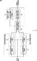
次に、図3は、画像処理装置12の第1の構成例を示している。画像処理装置12の第1の構成例は、特に、動画像上における動物体と静止物体とを相互に継続的に追尾できるようにするものである。<First Configuration Example of
Next, FIG. 3 shows a first configuration example of the
画像処理装置12の第1の構成例は、短期背景画像更新部21、短期背景差分計算部22、長期背景画像更新部23、長期背景差分計算部24、背景差分選択部25、物体位置計算部26、および物体停止時間カウント部27から構成される。 A first configuration example of the
短期背景画像更新部21は、入力画像に対して速やかに追従する短期背景画像を保持しており、前段の撮像装置11から入力画像の現フレームが入力される毎に、保持する短期背景画像を更新するとともに、更新した短期背景画像を短期背景差分計算部22に出力する。なお、短期背景画像の更新は、例えば次式(1)に従って同一座標の画素毎に行われる。 The short-term background
It+1=αs×It+(1−αs)×Ic
・・・(1)
ただし、
It+1は更新後の短期背景画像の画素の輝度値
Itは更新前の短期背景画像の画素の輝度値
Icは入力画像の画素の輝度値
αsは0以上1未満の短期更新係数
である。I t + 1 = α s × I t + (1-α s) × I c
... (1)
However,
I t+ 1 is the brightness value It of the pixel of the short-term background image the updated brightness value Ic of the pixels of the short-term background image before updating luminance value alphas of the pixels of the
短期背景差分計算部22は、入力画像の現フレームと短期背景画像の対応する画素どうしの輝度値の差分を算出し、その結果を短期差分として背景差分選択部25に出力する。 The short-term background
長期背景画像更新部23は、入力画像に対してゆっくりと追従する長期背景画像を保持しており、前段の撮像装置11から入力画像の現フレームが入力される毎に、保持する長期背景画像を更新するとともに、更新した長期背景画像を長期背景差分計算部24に出力する。なお、長期背景画像の更新は、例えば次式(2)に従って同一座標の画素毎に行われる。 The long-term background
It+1=αl×It+(1−αl)×Ic
・・・(2)
ただし、
It+1は更新後の短期背景画像の画素の輝度値
Itは更新前の短期背景画像の画素の輝度値
Icは入力画像の画素の輝度値
αlはαsよりも大きく、かつ、0以上1未満の長期更新係数
である。It + 1 = αl × It + (1−αl ) × Ic
... (2)
However,
I t+ 1 is the brightness value It of the pixel of the short-term background image the updated luminance value Ic of the pixels of the short-term background image before the update luminance value alphal of the pixels of the input image is greater than alphas, and , 0 or more and less than 1.
長期背景差分計算部24は、入力画像の現フレームと長期背景画像の対応する画素どうしの輝度値の差分を算出し、その結果を長期差分として背景差分選択部25に出力する。 The long-term background
なお、短期背景画像および長期背景画像の生成、更新については、上述した式(1),(2)を用いる方法に限定するものではなく、例えば、混合ガウス分布を用いた背景モデル(C. Stauffer and W.E.L. Grimson, “Adaptive background mixture models for real-time tracking,” Proc. IEEE CVPR 1999, pp. 24&252, June 1999.)を用いたり、カーネル密度推定(A. Elgammal, D. Hanvood, and L.S. Davis, “Nonparametric model for background subtraction,” Proc. ECCV 2000, pp. 751-767, June 2000.)を用いたりしてもよい。 The generation and update of the short-term background image and the long-term background image are not limited to the methods using the above-described equations (1) and (2). For example, a background model (C. Stauffer and WEL Grimson, “Adaptive background mixture models for real-time tracking,” Proc. IEEE CVPR 1999, pp. 24 & 252, June 1999.) and kernel density estimation (A. Elgammal, D. Hanvood, and LS Davis, “Nonparametric model for background subtraction,” Proc. ECCV 2000, pp. 751-767, June 2000) may be used.
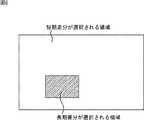
背景差分選択部25は、短期背景差分計算部22から入力される短期差分、または長期背景差分計算部24から入力される長期差分の一方を画素毎に選択することにより、差分画像を生成して物体位置計算部26に出力する。具体的には、前フレームにおいて特定された物体領域のうち、停止カウント値(後述)が所定の長短選択閾値以上である物体領域(長く停止している物体の領域)に属する画素については、長期差分を選択し、その他の画素については短期差分を選択して差分画像を生成する。 The background
なお、入力画像の全画素について、短期差分と長期差分の両方を計算して一方を選択するのではなく、前フレームにおいて特定された物体領域のうち、停止カウント値が所定の長短選択閾値以上である物体領域に属する画素についてだけ長期差分を計算し、その他の画素については短期差分だけを計算するようにしてもよい。 Note that, instead of calculating both the short-term difference and the long-term difference and selecting one of them for all the pixels of the input image, the stop count value of the object region specified in the previous frame is equal to or greater than a predetermined long / short selection threshold. The long-term difference may be calculated only for pixels belonging to a certain object region, and only the short-term difference may be calculated for other pixels.
物体位置計算部26は、背景差分選択部25から入力される差分画像の画素の画素値(長期差分、または短期差分)に着目し、その値が所定の差分閾値以上である画素を抽出し、隣接する画素が抽出された場合にはそれらをグルーピングすることにより物体領域候補を生成して、各物体領域候補に対して新たな物体IDを付与する。 The object
また、物体位置計算部26は、前のフレームにおいて特定した物体領域毎に、現フレームの物体領域候補の中で最も距離が近いものを特定し、その距離が所定の距離閾値以下である場合には、該物体領域候補に前記フレームにおける物体領域の物体IDを引き継がせる。さらに、前フレームの物体領域と、現フレームの物体領域候補の位置に基づいて、現フレームにおける物体領域の位置を計算する。具体的には、次式(3)に従って現フレームにおける物体領域の位置を計算する。 In addition, the object
xt+1=β×xt+(1−β)×x0
・・・(3)
ただし、
xt+1は現フレームにおいて特定する物体領域の位置ベクトル
xtは前フレームにおいて特定された物体領域の位置ベクトル
Icは現フレームにおける物体領域候補の位置ベクトル
βは更新係数
である。xt + 1 = β × xt + (1−β) × x0
... (3)
However,
x t+ 1 is the position vector Ic is the position vector β is updated coefficient object region candidate in the current frame of the specified object region at position vector xt is the previous frame of the object area to be identified in the current frame.
なお、現フレームにおける物体領域の位置の計算については、上述した式(3)を用いる方法に限定するものではなく、例えば、カルマンフィルタ(R. E. Kalman, “A New Approach to Linear Filtering and Prediction Problems”, J. Fluids Eng. 82(1), 35-45 (Mar 01, 1960))など他の方法を用いるようにしてもよい。 Note that the calculation of the position of the object region in the current frame is not limited to the method using Equation (3) described above. For example, a Kalman filter (RE Kalman, “A New Approach to Linear Filtering and Prediction Problems”, J Fluids Eng. 82 (1), 35-45 (Mar 01, 1960)) may be used.
さらに、物体位置計算部26は、現フレームの物体領域候補であって、前フレームで特定された物体領域の物体IDを引き継いでいないものについては、そのまま物体領域として特定し、全ての物体領域の位置情報と物体IDを後段の表示装置13、背景差分選択部25、および物体停止時間カウント部27に出力する。 Further, the object
物体停止時間カウント部27は、特定された物体領域の物体IDに停止カウント値を対応付けたカウントテーブルを保持している。そして、物体停止時間カウント部27は、前フレームにおいて特定された物体領域と、その物体IDが引き継がれた、現フレームにおいて特定された物体領域との位置の差が所定の停止判定閾値以下であるか否かを判定する。両者の位置の差が停止判定閾値以下であると判定された場合、該物体領域は停止しているものとして、物体停止時間カウント部27は、カウントテーブルにおける該物体領域の物体IDに対応付けられている停止カウント値を1だけカウントアップする。反対に、両者の位置の差が停止判定閾値よりも大きいと判定された場合、該物体領域は移動したものとして、物体停止時間カウント部27は、カウントテーブルにおける該物体領域の物体IDに対応付けられている停止カウント値を0にリセットする。 The object stop
図4は、現フレーム上で物体領域が特定された場合の例を示している。同図の場合、画面の左下の自動車と、右上の自動車が物体領域として検出されており、それぞれには物体IDとしてID:1とID:3が付与されている。 FIG. 4 shows an example in which an object region is specified on the current frame. In the case of the figure, the vehicle at the lower left of the screen and the vehicle at the upper right are detected as object regions, and ID: 1 and ID: 3 are assigned to them as object IDs.
図5は、図4に対応するカウンタテーブルの一例を示している。同図の場合、物体ID:1の物体領域の停止カウント値は10であり、物体ID:3の物体領域の停止カウント値は0である。これは、物体ID:1の物体領域が停止してから10フレームが経過したことを意味し、物体ID:3の物体領域が移動していることを意味する。ここで、例えば、長短選択閾値が5であると仮定すれば、次のフレームの差分画像が生成される際に、長短選択閾値=5よりも停止カウント値が大きい物体ID:1の物体領域については長期差分が選択され、その他の領域については短期差分が選択されることになる。 FIG. 5 shows an example of the counter table corresponding to FIG. In the case of the drawing, the stop count value of the object area of the object ID: 1 is 10 and the stop count value of the object area of the object ID: 3 is 0. This means that 10 frames have elapsed since the stop of the object area of the object ID: 1, and that the object area of the object ID: 3 is moving. Here, for example, assuming that the long / short selection threshold value is 5, when the difference image of the next frame is generated, the object count of the object ID: 1 having the stop count value larger than the long / short selection threshold value = 5 Is selected for the long-term difference, and the short-term difference is selected for the other regions.
<画像処理装置12の第1の構成例による物体検出処理>
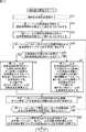
次に、図7は、画像処理装置12の第1の構成例による物体検出処理を説明するフローチャートである。<Object detection processing according to first configuration example of
Next, FIG. 7 is a flowchart illustrating an object detection process according to the first configuration example of the
この物体検出処理は、撮像装置11から画像処理装置12に入力される入力画像の各フレームに対して実行される。 This object detection processing is executed for each frame of the input image input from the
ステップS1において、短期背景画像更新部21は、入力画像の現フレームに基づき、保持する短期背景画像を更新し、更新した短期背景画像を短期背景差分計算部22に出力する。短期背景差分計算部22は、入力画像の現フレームと短期背景画像の対応する画素どうしの輝度値の差分を算出し、その結果を短期差分として背景差分選択部25に出力する。 In step S <b> 1, the short-term background
ステップS2において、長期背景画像更新部23は、入力画像の現フレームに基づき、保持する長期背景画像を更新し、更新した長期背景画像を長期背景差分計算部24に出力する。長期背景差分計算部24は、入力画像の現フレームと長期背景画像の対応する画素どうしの輝度値の差分を算出し、その結果を長期差分として背景差分選択部25に出力する。 In step S2, the long-term background
なお、上述したステップS1の処理とステップS2の処理とは、平行して実行することができる。 Note that the processing in step S1 and the processing in step S2 described above can be executed in parallel.
ステップS3において、背景差分選択部25は、前フレームにおいて特定された物体領域のうち、停止カウント値が所定の長短選択閾値以上である物体領域に属する画素については、長期差分を選択し、その他の画素については短期差分を選択して差分画像を生成する。 In step S3, the background
ステップS4において、物体位置計算部26は、背景差分選択部25から入力された差分画像の画素の画素値に着目し、その値が所定の差分閾値以上である画素を抽出し、隣接する画素が抽出された場合にはそれらをグルーピングすることにより物体領域候補を生成して、各物体領域候補に対して新たな物体IDを付与する。 In step S4, the object
ステップS5において、物体位置計算部26は、前のフレームにおいて特定した物体領域を一つずつ注目物体領域に指定する。ステップS6において、物体位置計算部26は、現フレームの物体領域候補のから、注目物体領域と距離が所定の距離閾値以下であって、その距離が最も近いものを特定し、特定した該物体領域候補に前記フレームにおける注目物体領域の物体IDを引き継がせる。さらに、物体位置計算部26は、前フレームの注目物体領域と、現フレームの物体領域候補の位置に基づいて、現フレームにおける物体領域の位置を計算し、計算結果を現フレームの物体領域として特定する。さらに、物体位置計算部26は、特定した現フレームの物体領域の位置情報と物体IDを後段の表示装置13、背景差分選択部25、および物体停止時間カウント部27に出力する。 In step S5, the object
ステップS7において、物体停止時間カウント部27は、前フレームにおいて特定された物体領域と、その物体IDが引き継がれた、現フレームにおいて特定された物体領域との位置の差が所定の停止判定閾値以下であるか否かを判定し、判定結果が肯定(YES)である場合、ステップS8に進み、該物体領域は停止しているものとして、カウントテーブルにおける該物体領域の物体IDに対応付けられている停止カウント値を1だけカウントアップする。反対に、判定結果が否定(NO)である場合、ステップS9に進み、該物体領域は移動したものとして、カウントテーブルにおける該物体領域の物体IDに対応付けられている停止カウント値を0にリセットする。 In step S7, the object stop
ステップS10において、物体位置計算部26は、前のフレームにおいて特定した物体領域の全てを注目物体領域に指定したか否かを判定する。この判定結果が否定である場合、注目物体領域に指定していないものが残っているので、処理はステップS5に戻され、それ以降が繰り返される。その後、ステップS10における判定結果が肯定(YES)となった場合、処理はステップS11に進められる。 In step S10, the object
ステップS11において、物体位置計算部26は、現フレームの物体領域候補であって、前フレームで特定された物体領域の物体IDを引き継いでいないものについては、そのまま物体領域に特定し、その位置情報と物体IDを後段の表示装置13、背景差分選択部25、および物体停止時間カウント部27に出力する。以上で、物体検出処理は終了される。 In step S11, the object
以上に説明した物体検出処理をフレーム毎に実行することにより、動画像に継続して登場する物体については、その動きや停止に拘わらず、継続して同一の物体IDを付与したまま追尾することができる。また、新たに出現した物体に対しては、新しい物体IDを付与することができる。 By executing the above-described object detection processing for each frame, an object continuously appearing in a moving image can be tracked while the same object ID is continuously provided regardless of the movement or the stop. Can be. In addition, a new object ID can be assigned to a newly appearing object.
よって、長期的に停止している物体も含めて物体の経路を特定することが可能となる。監視システム10の具体的に適用例としては、長期間にわたって停止したりうろついたりしている人を不信人物として発見したり、渋滞などで自動車が長時間停車している場合でも正しく交通流量を計測できるなど、長時間停止する被写体を追跡することが可能になる。 Therefore, it is possible to specify the path of the object including the object that has been stopped for a long time. As a specific application example of the
<画像処理装置12の第2の構成例>
次に、画像処理装置12の第2の構成例をついて説明する。画像処理装置12の第2の構成例は、特に、動画像上において物体の全体が見える状態から、その一部分だけが見える状態となった場合においても、その物体を継続的に追尾できるようにするものである。<Second Configuration Example of
Next, a second configuration example of the
図8は、画像処理装置12の第2の構成例の動作概要を説明するためのものであり、人物の全身を検出する場合を例にしている。 FIG. 8 is for explaining the outline of the operation of the second configuration example of the
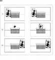
従来、人物の全身を検出対象としている場合、同図の左側の列に示すように、時刻t1のフレームでは人物の全身が検出されてID:1が付与されるが、時刻t2のフレームのように、全身の一部分(同図の場合、頭部)だけが見えている場合、全身を検出対象としているので何も検出されない。そして、時刻t3のフレームでは、人物の全身が検出されるものの、改めてID:2が付与されてしまうことになる。 Conventionally, when the whole body of a person is to be detected, the whole body of the person is detected and assigned ID: 1 in the frame at time t1, as shown in the left column of FIG. If only a part of the whole body (in the case of the figure, the head) is visible, nothing is detected because the whole body is to be detected. Then, in the frame at time t3, although the whole body of the person is detected, ID: 2 is added again.
これに対して、画像処理装置12の第2の構成例は、時刻t2のフレームのように、全身の一部分(同図の場合、頭部)だけが見えている場合にも、時刻t2のフレームの全身に付与されたIDと同一のIDが付与されるようにし、さらに、時刻t3のフレームにように再び全身が見えた場合にも、時刻t2のフレームの頭部に付与されたIDと同一のIDが付与されるようにするものである。 On the other hand, in the second configuration example of the
図9は、画像処理装置12の第2の構成例を示している。画像処理装置12の第2の構成例は、頭部検出領域設定部31、頭部検出部32、全身検出部33、検出手法選択部34、人位置検出部35、および頭部中心座標計算部36から構成される。 FIG. 9 shows a second configuration example of the
頭部検出領域設定部31は、オペレータの操作に基づき、図10に示されるように、撮像範囲の中に遮蔽物が存在することにより、該遮蔽物が人の全身の一部を隠してしまい、頭部だけしか見えなくなってしまう可能性がある領域を頭部検出領域51に設定して、頭部検出部32、全身検出部33、検出手法選択部34および頭部中心座標計算部36に通知する。 Based on the operation of the operator, the head detection
頭部検出部32は、前段の撮像装置11から入力画像の現フレームが入力される毎に、その頭部検出領域51内から人の頭部を検出し、検出結果に新たな物体IDを付与して頭部領域候補として検出手法選択部34に出力する。全身検出部33は、前段の撮像装置11から入力画像の現フレームが入力される毎に、その頭部検出領域51以外から人の全身を検出し、検出結果に新たな物体IDを付与して全身領域候補として検出手法選択部34に出力する。 Each time the current frame of the input image is input from the preceding
なお、頭部検出部32における頭部検出や全身検出部33における全身検出には、例えば、(Navneet Dalal and Bill Triggs, “Histogramsof Oriented Gradients for Human Detection”, “International Conference on Computer Vision & Pattern Recognition (CVPR '05) 1 (2005) 886--893")などに記載されている機械学習を用いた方法などの既存の任意の方法を採用することができる。 For example, (Navneet Dalal and Bill Triggs, “Histograms of Oriented Gradients for Human Detection”, “International Conference on Computer Vision & Pattern Recognition ( CVPR '05) 1 (2005) 886--893 ") or any other existing method such as a method using machine learning.
検出手法選択部34は、前フレームにおいて特定された頭部領域および全身領域を一つずつ注目領域に指定し、注目領域の頭部の中心座標が頭部検出領域51内にある場合には、現フレームの頭部領域候補の中から、注目領域の頭部の中心座標との距離が所定の距離閾値以内であって最も近いものを特定し、該頭部領域候補に注目領域の物体IDを引き継がせる。 The detection
また、検出手法選択部34は、注目領域の頭部の中心座標が頭部検出領域51内にない場合には、現フレームの全身領域候補の中から、注目領域の頭部の中心座標との距離が所定の距離閾値以内であって最も近いものを特定し、該全身領域候補に注目領域の物体IDを引き継がせる。 In addition, when the center coordinates of the head of the attention area are not within the
なお、頭部検出部32および全身検出部33が、入力画像の全領域からそれぞれ頭部領域候補、または全身領域候補を検出するようにし、検出手法選択部34が、頭部領域候補については頭部検出領域51内から検出されたものだけを採用し、全身領域候補については頭部検出領域51以外から検出されたものだけを採用するようにしてもよい。 Note that the
人位置計算部35は、前フレームの注目領域と、その物体IDを引き継いだ現フレームの頭部領域候補(または全身領域候補)の位置に基づいて、現フレームにおける頭部領域(または全身領域候補)の位置を計算し、計算結果を現フレームの頭部領域(または全身領域候補)として特定する。なお、頭部領域(または全身領域候補)の位置を計算には、上述した式(3)を用いることができる。 The human
また、人位置計算部35は、特定した現フレームの頭部領域および全身領域の位置情報と物体IDを後段の表示装置13、検出手法選択部34、および頭部中心座標計算部36に出力する。 Further, the human
頭部中心座標計算部36は、次のフレームに対する処理で用いるため、現フレームで特定した全身領域と頭部領域それぞれの頭部の中心座標を計算し、計算結果を検出手法選択部34に出力する。 The head center coordinate
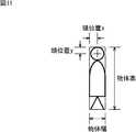
図11は、全身領域の頭部の中心座標の計算方法を説明する図である。全身領域の頭部の中心座標の計算する場合、特定された全身領域の外接矩形サイズから次式(4)に従って頭部の中心座標(x,y)を計算する。
x=物体幅/2
y=物体高×平均顔サイズ/平均身長/2
・・・(4)
ただし、平均顔サイズと平均身長は、この監視システム10が使われる地域、すなわち、被写体となり得る人種などの平均値を予め設定しておくものとする。FIG. 11 is a diagram illustrating a method of calculating the center coordinates of the head of the whole body region. When calculating the center coordinates of the head of the whole body region, the center coordinates (x, y) of the head are calculated from the specified circumscribed rectangle size of the whole body region according to the following equation (4).
x = object width / 2
y = object height × average face size / average height / 2
... (4)
However, as the average face size and average height, it is assumed that an average value of an area where the
図12は、頭部頭域の中心座標の計算方法を説明する図である。頭部領域の中心座標の計算この場合、特定される頭部領域の外接矩形サイズから次式(5)に従って頭部の中心座標(x,y)を計算する。
x=物体幅/2
y=物体高/2
・・・(5)FIG. 12 is a diagram illustrating a method of calculating the center coordinates of the head area. Calculation of the center coordinates of the head region In this case, the center coordinates (x, y) of the head are calculated from the circumscribed rectangle size of the specified head region according to the following equation (5).
x = object width / 2
y = object height / 2
... (5)
<画像処理装置12の第2の構成例による物体検出処理>
次に、図13は、画像処理装置12の第2の構成例による物体検出処理を説明するフローチャートである。<Object detection processing according to second configuration example of
Next, FIG. 13 is a flowchart illustrating an object detection process according to the second configuration example of the
この物体検出処理は、撮像装置11から画像処理装置12に入力される入力画像の各フレームに対して実行される。 This object detection processing is executed for each frame of the input image input from the
ステップS31において、頭部検出領域設定部31は、オペレータの操作に基づき、頭部検出領域51に設定して、頭部検出部32、全身検出部33、検出手法選択部34および頭部中心座標計算部36に通知する。 In step S31, the head detection
ステップS32において、頭部検出部32は、入力画像の現フレームの頭部検出領域51内から人の頭部を検出し、検出結果に新たな物体IDを付与して頭部領域候補として検出手法選択部34に出力する。ステップS33において、全身検出部33は、入力画像の現フレームの頭部検出領域51以外から人の全身を検出し、検出結果に新たな物体IDを付与して全身領域候補として検出手法選択部34に出力する。 In step S32, the
なお、上述したステップS32の処理とステップS33の処理とは、平行して実行することができる。 Note that the processing of step S32 and the processing of step S33 described above can be executed in parallel.
ステップS34において、検出手法選択部34は、前フレームにおいて特定された頭部領域および全身領域を一つずつ注目領域に指定する。ステップS35において、検出手法選択部34は、注目領域の頭部の中心座標が頭部検出領域51内にあるか否かを判定する。この判定結果が肯定(YES)である場合、処理はステップS36に進められる。反対に、判定結果が否定(NO)である場合、処理はステップS37に進められる。 In step S34, the detection
例えば、前フレームから図14に示されるように、二つの全身領域と、一つの頭部領域が特定されていて、頭部検出領域51内の頭部領域が注目領域に指定されている場合には処理はステップS36に進められる。また、二つの全身領域のどちらかが注目領域に指定されている場合には処理はステップS37に進められる。 For example, as shown in FIG. 14 from the previous frame, when two whole body regions and one head region are specified, and the head region in the
ステップS36においては、検出手法選択部34は、現フレームから検出された頭部領域候補の中から、注目領域の頭部の中心座標との距離が所定の距離閾値以内であって最も近いものを特定し、該頭部領域候補に注目領域の物体IDを引き継がせる。人位置計算部35は、前フレームの注目領域と、その物体IDを引き継いだ現フレームの頭部領域候補の位置に基づいて、現フレームにおける頭部領域の位置を計算し、計算結果を現フレームの頭部領域として特定する。そして、人位置計算部35は、特定した現フレームの頭部領域の位置情報と物体IDを後段の表示装置13、検出手法選択部34、および頭部中心座標計算部36に出力する。 In step S36, the detection
一方、ステップS37においては、検出手法選択部34は、現フレームから検出された全身領域候補の中から、注目領域の頭部の中心座標との距離が所定の距離閾値以内であって最も近いものを特定し、該全身領域候補に注目領域の物体IDを引き継がせる。人位置計算部35は、前フレームの注目領域と、その物体IDを引き継いだ現フレームの全身領域候補の位置に基づいて、現フレームにおける全身領域の位置を計算し、計算結果を現フレームの全身領域として特定する。そして、人位置計算部35は、特定した現フレームの全身領域の位置情報と物体IDを後段の表示装置13、検出手法選択部34、および頭部中心座標計算部36に出力する。 On the other hand, in step S37, the detection
ステップS38において、頭部中心座標計算部36は、現フレームで特定した頭部領域または全身領域の頭部の中心座標を計算し、計算結果を検出手法選択部34に出力する。 In step S38, the head center coordinate
ステップS39において、検出手法選択部34は、前フレームにおいて特定された頭部領域および全身領域の全てを注目領域に指定したか否かを判定する。この判定結果が否定である場合、注目領域に指定していないものが残っているので、処理はステップS34に戻されてそれ以降が繰り返される。その後、ステップS39における判定結果が肯定である場合、処理はステップS40に進められる。 In step S39, the detection
ステップS40において、人位置計算部35は、現フレームの頭部領域候補または全身領域候補であって、前フレームで特定された頭部領域または全身領域の物体IDを引き継いでいないものについては、そのまま頭部領域または全身領域に特定し、その位置情報と物体IDを後段の表示装置13、背景差分選択部25、および物体停止時間カウント部27に出力する。以上で、物体検出処理は終了される。 In step S40, the human
以上に説明した物体検出処理をフレーム毎に実行することにより、動画像に継続して登場する物体については、その一部が隠れたとしても、継続して同一の物体IDを付与したまま追尾することができる。また、新たに出現した物体に対しては、新しい物体IDを付与することができる。 By executing the above-described object detection processing for each frame, an object continuously appearing in a moving image is tracked with the same object ID continuously provided even if a part of the object is hidden. be able to. In addition, a new object ID can be assigned to a newly appearing object.
監視システム10の具体的に適用例としては、工場の作業効率化検討のための作業員の動線解析や、客がどういう行動をとったかを記録してその情報をマーケティング利用するといったことも可能になる。 As a specific application example of the
なお、画像処理装置12の第2の構成例は、全身のうちの頭部だけが見える場合について説明したが、例えば、頭部以外の身体のパーツに関する特徴量(顔の特徴量,スポーツ選手等が着用するユニフォーム・作業服の固有のマークに関する特徴量など)を学習しておけば、それらを検出して追尾することも可能となる。 Although the second configuration example of the
ところで、画像処理装置12の上述した一連の処理は、ハードウェアにより実行することもできるし、ソフトウェアにより実行することもできる。一連の処理をソフトウェアにより実行する場合には、そのソフトウェアを構成するプログラムが、コンピュータにインストールされる。ここで、コンピュータには、専用のハードウェアに組み込まれているコンピュータや、各種のプログラムをインストールすることで、各種の機能を実行することが可能な、例えば汎用のパーソナルコンピュータなどが含まれる。 Incidentally, the above-described series of processes of the
図15は、上述した一連の処理をプログラムにより実行するコンピュータのハードウェアの構成例を示すブロック図である。 FIG. 15 is a block diagram illustrating a configuration example of hardware of a computer that executes the series of processes described above by a program.
コンピュータ200において、CPU(Central Processing Unit)201,ROM(Read Only Memory)202,RAM(Random Access Memory)203は、バス204により相互に接続されている。 In the
バス204には、さらに、入出力インタフェース205が接続されている。入出力インタフェース205には、入力部206、出力部207、記憶部208、通信部209、およびドライブ210が接続されている。 The
入力部206は、キーボード、マウス、マイクロフォンなどよりなる。出力部207は、ディスプレイ、スピーカなどよりなる。記憶部208は、ハードディスクや不揮発性のメモリなどよりなる。通信部209は、ネットワークインタフェースなどよりなる。ドライブ210は、磁気ディスク、光ディスク、光磁気ディスク、又は半導体メモリなどのリムーバブルメディア211を駆動する。 The
以上のように構成されるコンピュータでは、CPU201が、例えば、記憶部208に記憶されているプログラムを、入出力インタフェース205およびバス204を介して、RAM203にロードして実行することにより、上述した一連の処理が行われる。 In the computer configured as described above, the
なお、コンピュータ200が実行するプログラムは、本明細書で説明する順序に沿って時系列に処理が行われるプログラムであってもよいし、並列に、あるいは呼び出しが行われたとき等の必要なタイミングで処理が行われるプログラムであってもよい。 Note that the program executed by the
なお、本開示の実施の形態は、上述した実施の形態に限定されるものではなく、本開示の要旨を逸脱しない範囲において種々の変更が可能である。 Note that the embodiments of the present disclosure are not limited to the above-described embodiments, and various changes can be made without departing from the spirit of the present disclosure.
11 撮像装置, 12 画像処理装置, 13 表示装置, 21 短期背景画像更新部, 22 短期背景差分計算部, 23 長期背景画像更新部, 24 長期背景差分計算部, 25 背景差分選択部, 26 物体位置計算部, 27 物体停止時間カウント部, 31 頭部検出領域設定部, 32 頭部検出部, 33 全身検出部, 34 検出手法選択部, 35 人位置計算部, 36 頭部中心座標計算部, 51 頭部検出領域, 200 コンピュータ, 201 CPU
Claims (7)
Translated fromJapanese前記動画像の現フレームから、それぞれが異なる基準に基づいて画像上の物体に関する物体特徴量を計算する複数の物体特徴量計算部と、
前記動画像の前フレーム上の物体に関する物体属性情報を利用して、前記異なる基準に基づいて計算された複数の前記物体特徴量の中から利用する物体特徴量を選択する特徴量選択部と、
選択された前記特徴量と、前記前フレーム上の物体に関する物体情報としての位置ベクトルを用いて、現フレーム上の物体に関する物体情報としての位置ベクトルを計算する物体情報計算部と、
計算された現フレーム上の物体に関する前記物体情報としての前記位置ベクトルに基づき、現フレーム上の物体に関する物体属性情報を計算する物体属性情報計算部と
を備える画像処理装置。In an image processing device that detects an object on a moving image,
From the current frame of the moving image, a plurality of object feature amount calculation units that calculate the object feature amount of the object on the image based on different criteria,
A feature amount selecting unit that selects an object feature amount to be used from among the plurality of object feature amounts calculated based on the different criterion, using object attribute information on an object on a previous frame of the moving image;
An object information calculation unit that calculates aposition vector as object information on an object on the current frame using the selected feature amount anda position vector as object information on the object on the previous frame,
An object attribute information calculation unit that calculates object attribute information on the object on the current frame based on the calculatedposition vector as the object information on the object on the current frame.
短期背景画像と前記現フレームとの対応する画素の輝度の差分を第1の物体特徴量として計算する第1の物体特徴量計算部と、
長期背景画像と前記現フレームとの対応する画素の輝度の差分を第2の物体特徴量として計算する第2の物体特徴量計算部とを有し、
前記特徴量選択部は、前記前フレーム上の物体に関する物体属性情報としての停止カウント値を利用して、画素毎に前記第1または第2の特徴量を選択することにより差分画像を生成し、
前記物体位置計算部は、生成された前記差分画像と、前記前フレーム上の物体に関する物体情報としての前記位置ベクトルを用いて、現フレーム上の物体に関する物体情報としての前記位置ベクトルを計算し、
前記物体属性情報計算部は、計算された現フレーム上の物体に関する前記物体情報としての前記位置ベクトルに基づき、現フレーム上の物体に関する前記物体属性情報としての前記停止カウント値をカウントする
請求項1に記載の画像処理装置。The plurality of object feature quantity calculation units,
A first object feature value calculation unit that calculates a difference in luminance between pixels corresponding to the short-term background image and the current frame as a first object feature value;
A second object feature value calculation unit that calculates a difference in luminance between pixels corresponding to the long-term background image and the current frame as a second object feature value;
The feature amount selecting unit generates a difference image by selecting the first or second feature amount for each pixel using a stop count value as object attribute information on the object on the previous frame,
The object position calculating unit includes a generated the difference image, usingthe position vector of the object information about the object on the previous frame, and calculatingthe position vector of the object information about the object on the current frame,
The object attribute information calculation unit counts the stop count value as the object attribute information on the object on the current frame based on the calculated position vector as the object information on the object on the current frame. An image processing apparatus according to claim 1.
請求項2に記載の画像処理装置。The object position calculation unit detects an object candidate on the current frame based on the generated difference image, and, for the object candidate on the current frame closest to the object on the previous frame, the The image processing device according to claim 2, wherein an object ID assigned to the object on a frame is taken over.
前記複数の物体特徴量計算部は、
前記現フレームの前記頭部検出領域以外から人の全身領域候補を第1の物体特徴量として計算する第1の物体特徴量計算部と、
前記現フレームの前記頭部検出領域から人の頭部領域候補を第2の物体特徴量として計算する第2の物体特徴量計算部とを有し、
前記特徴量選択部は、前記前フレームの全身領域および頭部領域を一つずつ注目領域に指定し、前記注目領域の頭部の中心座標が前記頭部検出領域内にあるか否かに応じて、前記現フレームの前記全身領域候補または前記頭部領域候補を選択して、現フレームの全身領域または頭部領域に特定し、
前記物体位置計算部は、前記前フレーム上の物体に関する物体情報としての前記注目領域の前記位置ベクトルを用いて、現フレーム上の物体に関する物体情報として、特定された前記全身領域または前記頭部領域の前記位置ベクトルを計算し、
前記物体属性情報計算部は、計算された現フレーム上の物体に関する前記物体情報としての前記全身領域または前記頭部領域の前記位置ベクトルに基づき、現フレーム上の物体に関する前記物体属性情報として、前記全身領域の頭部の中心座標または前記頭部領域の中心座標を計算する
請求項1に記載の画像処理装置。Further comprising a head detection area setting unit for setting a head detection area,
The plurality of object feature quantity calculation units,
A first object feature value calculation unit that calculates a human whole body region candidate as a first object feature value from a portion other than the head detection region of the current frame;
A second object feature value calculation unit that calculates a human head region candidate from the head detection region of the current frame as a second object feature value;
The feature amount selection unit designates the whole body region and the head region of the previous frame one by one as a region of interest, and determines whether a center coordinate of a head of the region of interest is within the head detection region. Selecting the whole body region candidate or the head region candidate of the current frame, and specifying the whole body region or the head region of the current frame,
The object position calculation unit usesthe position vector of the region of interest as the object information on an object on the previous frame, as the object information on the object on the current frame, the whole body region or the head region identifiedthe position vector and the calculation of,
The object attribute information calculation unit is based on the calculated position vector of the whole body region or the head region as the object information on the object on the current frame, and as the object attribute information on the object on the current frame, The image processing apparatus according to claim 1, wherein central coordinates of a head of the whole body region or central coordinates of the head region are calculated.
前記注目領域の頭部の中心座標が前記頭部検出領域内にある場合、前記注目領域に最も距離が近い前記現フレームの前記頭部領域候補を選択して、前記注目領域の物体IDを引き継がせて、現フレームの頭部領域に特定し、
前記注目領域の頭部の中心座標が前記頭部検出領域内にない場合、前記注目領域に最も距離が近い前記現フレームの前記全身領域候補を選択して、前記注目領域の物体IDを引き継がせて、現フレームの全身領域に特定する
請求項4に記載の画像処理装置。The feature amount selection unit includes:
When the center coordinates of the head of the attention area are within the head detection area, the head area candidate of the current frame closest to the attention area is selected, and the object ID of the attention area is taken over. To identify the head region of the current frame,
If the center coordinates of the head of the region of interest are not within the head detection region, select the whole body region candidate of the current frame closest to the region of interest and take over the object ID of the region of interest. The image processing apparatus according to claim 4, wherein the image processing apparatus specifies the whole body area of the current frame.
前記画像処理装置による、
前記動画像の現フレームから、それぞれが異なる基準に基づいて画像上の物体に関する複数の物体特徴量を計算する物体特徴量計算ステップと、
前記動画像の前フレーム上の物体に関する物体属性情報を利用して、前記異なる基準に基づいて計算された複数の前記物体特徴量の中から利用する物体特徴量を選択する特徴量選択ステップと、
選択された前記特徴量と、前記前フレーム上の物体に関する物体情報としての位置ベクトルを用いて、現フレーム上の物体に関する物体情報としての位置ベクトルを計算する物体情報計算ステップと、
計算された現フレーム上の物体に関する前記物体情報としての前記位置ベクトルに基づき、現フレーム上の物体に関する物体属性情報を計算する物体属性情報計算ステップと
を含む画像処理方法。In an image processing method of an image processing device that detects an object on a moving image,
By the image processing device,
From the current frame of the moving image, an object feature amount calculation step of calculating a plurality of object feature amounts for an object on the image based on different criteria,
A feature amount selecting step of selecting an object feature amount to be used from among the plurality of object feature amounts calculated based on the different criterion, using object attribute information on an object on a previous frame of the moving image;
An object information calculating step of calculating aposition vector as object information on an object on the current frame using the selected feature amount anda position vector as object information on the object on the previous frame,
Calculating the object attribute information on the object on the current frame based on the calculatedposition vector as the object information on the object on the current frame.
前記動画像の現フレームから、それぞれが異なる基準に基づいて画像上の物体に関する物体特徴量を計算する複数の物体特徴量計算部と、
前記動画像の前フレーム上の物体に関する物体属性情報を利用して、前記異なる基準に基づいて計算された複数の前記物体特徴量の中から利用する物体特徴量を選択する特徴量選択部と、
選択された前記特徴量と、前記前フレーム上の物体に関する物体情報としての位置ベクトルを用いて、現フレーム上の物体に関する物体情報としての位置ベクトルを計算する物体情報計算部と、
計算された現フレーム上の物体に関する前記物体情報としての前記位置ベクトルに基づき、現フレーム上の物体に関する物体属性情報を計算する物体属性情報計算部と
して機能させるプログラム。A computer that detects objects on moving images
From the current frame of the moving image, a plurality of object feature amount calculation units that calculate the object feature amount of the object on the image based on different criteria,
A feature amount selecting unit that selects an object feature amount to be used from among the plurality of object feature amounts calculated based on the different criterion, using object attribute information on an object on a previous frame of the moving image;
An object information calculation unit that calculates aposition vector as object information on an object on the current frame using the selected feature amount anda position vector as object information on the object on the previous frame,
A program that functions as an object attribute information calculation unit that calculates object attribute information on an object on the current frame based on the calculatedposition vector as the object information on the object on the current frame.
Applications Claiming Priority (3)
| Application Number | Priority Date | Filing Date | Title |
|---|---|---|---|
| JP2014160416 | 2014-08-06 | ||
| JP2014160416 | 2014-08-06 | ||
| PCT/JP2015/070923WO2016021411A1 (en) | 2014-08-06 | 2015-07-23 | Image processing device, image processing method, and program |
Publications (2)
| Publication Number | Publication Date |
|---|---|
| JPWO2016021411A1 JPWO2016021411A1 (en) | 2017-05-18 |
| JP6675984B2true JP6675984B2 (en) | 2020-04-08 |
Family
ID=55263683
Family Applications (1)
| Application Number | Title | Priority Date | Filing Date |
|---|---|---|---|
| JP2016540146AExpired - Fee RelatedJP6675984B2 (en) | 2014-08-06 | 2015-07-23 | Image processing apparatus, image processing method, and program |
Country Status (4)
| Country | Link |
|---|---|
| US (1) | US10157327B2 (en) |
| JP (1) | JP6675984B2 (en) |
| CN (1) | CN106663325B (en) |
| WO (1) | WO2016021411A1 (en) |
Families Citing this family (10)
| Publication number | Priority date | Publication date | Assignee | Title |
|---|---|---|---|---|
| US10460194B2 (en)* | 2014-03-07 | 2019-10-29 | Lior Wolf | System and method for the detection and counting of repetitions of repetitive activity via a trained network |
| US10102423B2 (en)* | 2016-06-30 | 2018-10-16 | Snap Inc. | Object modeling and replacement in a video stream |
| JP6551491B2 (en)* | 2017-11-06 | 2019-07-31 | 京セラドキュメントソリューションズ株式会社 | Monitoring system |
| KR102778448B1 (en)* | 2017-12-26 | 2025-03-11 | 삼성전자주식회사 | Device for computing neural network operation, and method of operation thereof |
| JP7169752B2 (en)* | 2018-03-22 | 2022-11-11 | キヤノン株式会社 | MONITORING DEVICE, MONITORING SYSTEM, CONTROL METHOD, AND PROGRAM |
| US11990041B2 (en) | 2018-09-05 | 2024-05-21 | Nec Corporation | Moving body tracking system, moving body tracking method, and program |
| CN109785429B (en) | 2019-01-25 | 2020-08-21 | 北京极智无限科技有限公司 | Three-dimensional reconstruction method and device |
| JP7569169B2 (en)* | 2020-06-12 | 2024-10-17 | キヤノン株式会社 | Imaging device, control method and program thereof |
| JP7509044B2 (en)* | 2021-01-18 | 2024-07-02 | オムロン株式会社 | Information processing device and information processing method |
| JP7597431B1 (en)* | 2024-05-08 | 2024-12-10 | 株式会社アジラ | Behavior Prediction System |
Family Cites Families (15)
| Publication number | Priority date | Publication date | Assignee | Title |
|---|---|---|---|---|
| JP4425642B2 (en)* | 2004-01-08 | 2010-03-03 | 富士重工業株式会社 | Pedestrian extraction device |
| CN101231755B (en)* | 2007-01-25 | 2013-03-06 | 上海遥薇(集团)有限公司 | Moving target tracking and quantity statistics method |
| JP4623200B2 (en)* | 2008-10-27 | 2011-02-02 | ソニー株式会社 | Image processing apparatus, image processing method, and program |
| JP4623199B2 (en)* | 2008-10-27 | 2011-02-02 | ソニー株式会社 | Image processing apparatus, image processing method, and program |
| KR101183781B1 (en)* | 2009-12-22 | 2012-09-17 | 삼성전자주식회사 | Method and apparatus for object detecting/tracking using real time motion estimation of camera |
| JP2012133759A (en)* | 2010-11-29 | 2012-07-12 | Canon Inc | Object tracking device capable of detecting intrusion object, object tracking method, and storage medium |
| CN102289940B (en)* | 2011-07-26 | 2013-07-03 | 西南交通大学 | Hybrid differential-based traffic flow detection method |
| JP2013033317A (en) | 2011-08-01 | 2013-02-14 | Sony Corp | Image processing apparatus, image processing method, and program |
| CN102281385B (en)* | 2011-08-16 | 2013-03-27 | 上海交通大学 | Periodic motion detection method based on motion video |
| CN102496276B (en)* | 2011-12-01 | 2013-08-21 | 青岛海信网络科技股份有限公司 | High efficiency vehicle detection method |
| JP6046948B2 (en)* | 2012-08-22 | 2016-12-21 | キヤノン株式会社 | Object detection apparatus, control method therefor, program, and storage medium |
| JP5892075B2 (en)* | 2013-01-16 | 2016-03-23 | トヨタ自動車株式会社 | Object detection device and object detection method, alarm device and alarm method, driving support device and driving support method |
| CN103456009B (en)* | 2013-08-28 | 2016-04-20 | 深圳市中瀛鑫科技股份有限公司 | Object detection method and device, supervisory system |
| US9275286B2 (en)* | 2014-05-15 | 2016-03-01 | Xerox Corporation | Short-time stopping detection from red light camera videos |
| JP6618767B2 (en)* | 2015-10-27 | 2019-12-11 | 株式会社デンソーテン | Image processing apparatus and image processing method |
- 2015
- 2015-07-23USUS15/500,270patent/US10157327B2/enactiveActive
- 2015-07-23WOPCT/JP2015/070923patent/WO2016021411A1/enactiveApplication Filing
- 2015-07-23CNCN201580040748.7Apatent/CN106663325B/enactiveActive
- 2015-07-23JPJP2016540146Apatent/JP6675984B2/ennot_activeExpired - Fee Related
Also Published As
| Publication number | Publication date |
|---|---|
| WO2016021411A1 (en) | 2016-02-11 |
| JPWO2016021411A1 (en) | 2017-05-18 |
| US20170220894A1 (en) | 2017-08-03 |
| US10157327B2 (en) | 2018-12-18 |
| CN106663325B (en) | 2020-06-16 |
| CN106663325A (en) | 2017-05-10 |
Similar Documents
| Publication | Publication Date | Title |
|---|---|---|
| JP6675984B2 (en) | Image processing apparatus, image processing method, and program | |
| JP7428213B2 (en) | Information processing system, information processing method and program | |
| US10417503B2 (en) | Image processing apparatus and image processing method | |
| CN109076198B (en) | Video-based object tracking occlusion detection system, method and equipment | |
| JP5102410B2 (en) | Moving body detection apparatus and moving body detection method | |
| US8989448B2 (en) | Moving object detecting device, moving object detecting method, moving object detection program, moving object tracking device, moving object tracking method, and moving object tracking program | |
| EP2548174B1 (en) | Method and apparatus for trajectory estimation, and method for segmentation | |
| JP6655878B2 (en) | Image recognition method and apparatus, program | |
| CN105957110B (en) | Apparatus and method for detection object | |
| CN106934333B (en) | Gesture recognition method and system | |
| Cuevas et al. | Improved background modeling for real-time spatio-temporal non-parametric moving object detection strategies | |
| WO2013000404A1 (en) | Image detection method and device | |
| CN103475800B (en) | Method and device for detecting foreground in image sequence | |
| KR101139930B1 (en) | Apparatus and method for object recognition based on part-template matching | |
| CN107665495B (en) | Object tracking method and object tracking device | |
| Minematsu et al. | Evaluation of foreground detection methodology for a moving camera | |
| Badie et al. | Global tracker: an online evaluation framework to improve tracking quality | |
| KR20150047937A (en) | Method, apparatus and computer-readable recording medium for seperating the human and the background from the video | |
| JP2021077177A (en) | Operation recognition apparatus, operation recognition method, and operation recognition program | |
| JP6516609B2 (en) | Moving object detection apparatus and background model construction method | |
| Bhuvaneswari et al. | TRACKING MANUALLY SELECTED OBJECT IN VIDEOS USING COLOR HISTOGRAM MATCHING. | |
| Hati et al. | Review and improvement areas of mean shift tracking algorithm | |
| Chandrajit et al. | Motion Segmentation from Surveillance Video using modified Hotelling's T-Square Statistics | |
| Jeong et al. | Soft assignment and multiple keypoint analysis-based pedestrian counting method | |
| JP2015088027A (en) | Image processor, image processing method, and image processing program |
Legal Events
| Date | Code | Title | Description |
|---|---|---|---|
| A621 | Written request for application examination | Free format text:JAPANESE INTERMEDIATE CODE: A621 Effective date:20180705 | |
| A131 | Notification of reasons for refusal | Free format text:JAPANESE INTERMEDIATE CODE: A131 Effective date:20190829 | |
| A521 | Request for written amendment filed | Free format text:JAPANESE INTERMEDIATE CODE: A523 Effective date:20191017 | |
| TRDD | Decision of grant or rejection written | ||
| A01 | Written decision to grant a patent or to grant a registration (utility model) | Free format text:JAPANESE INTERMEDIATE CODE: A01 Effective date:20200213 | |
| A61 | First payment of annual fees (during grant procedure) | Free format text:JAPANESE INTERMEDIATE CODE: A61 Effective date:20200311 | |
| R150 | Certificate of patent or registration of utility model | Ref document number:6675984 Country of ref document:JP Free format text:JAPANESE INTERMEDIATE CODE: R150 | |
| LAPS | Cancellation because of no payment of annual fees |