JP6674847B2 - Motor stator assembling method and motor stator structure - Google Patents
Motor stator assembling method and motor stator structureDownload PDFInfo
- Publication number
- JP6674847B2 JP6674847B2JP2016110730AJP2016110730AJP6674847B2JP 6674847 B2JP6674847 B2JP 6674847B2JP 2016110730 AJP2016110730 AJP 2016110730AJP 2016110730 AJP2016110730 AJP 2016110730AJP 6674847 B2JP6674847 B2JP 6674847B2
- Authority
- JP
- Japan
- Prior art keywords
- wire
- crimping
- stator
- temporary holding
- connector
- Prior art date
- Legal status (The legal status is an assumption and is not a legal conclusion. Google has not performed a legal analysis and makes no representation as to the accuracy of the status listed.)
- Active
Links
- 238000000034methodMethods0.000titleclaimsdescription9
- 238000002788crimpingMethods0.000claimsdescription72
- 239000004020conductorSubstances0.000claimsdescription21
- 239000011248coating agentSubstances0.000claimsdescription7
- 238000000576coating methodMethods0.000claimsdescription7
- 230000002093peripheral effectEffects0.000description8
- 238000005452bendingMethods0.000description3
- 239000011347resinSubstances0.000description2
- 229920005989resinPolymers0.000description2
- 230000015572biosynthetic processEffects0.000description1
- 229910000679solderInorganic materials0.000description1
- 238000005476solderingMethods0.000description1
- 230000000087stabilizing effectEffects0.000description1
Images


Classifications
- H—ELECTRICITY
- H02—GENERATION; CONVERSION OR DISTRIBUTION OF ELECTRIC POWER
- H02K—DYNAMO-ELECTRIC MACHINES
- H02K15/00—Processes or apparatus specially adapted for manufacturing, assembling, maintaining or repairing of dynamo-electric machines
- H02K15/30—Manufacture of winding connections
- H02K15/33—Connecting winding sections; Forming leads; Connecting leads to terminals
- H—ELECTRICITY
- H01—ELECTRIC ELEMENTS
- H01R—ELECTRICALLY-CONDUCTIVE CONNECTIONS; STRUCTURAL ASSOCIATIONS OF A PLURALITY OF MUTUALLY-INSULATED ELECTRICAL CONNECTING ELEMENTS; COUPLING DEVICES; CURRENT COLLECTORS
- H01R4/00—Electrically-conductive connections between two or more conductive members in direct contact, i.e. touching one another; Means for effecting or maintaining such contact; Electrically-conductive connections having two or more spaced connecting locations for conductors and using contact members penetrating insulation
- H01R4/24—Connections using contact members penetrating or cutting insulation or cable strands
- H01R4/2495—Insulation penetration combined with permanent deformation of the contact member, e.g. crimping
- H—ELECTRICITY
- H02—GENERATION; CONVERSION OR DISTRIBUTION OF ELECTRIC POWER
- H02K—DYNAMO-ELECTRIC MACHINES
- H02K1/00—Details of the magnetic circuit
- H02K1/06—Details of the magnetic circuit characterised by the shape, form or construction
- H02K1/12—Stationary parts of the magnetic circuit
- H—ELECTRICITY
- H02—GENERATION; CONVERSION OR DISTRIBUTION OF ELECTRIC POWER
- H02K—DYNAMO-ELECTRIC MACHINES
- H02K15/00—Processes or apparatus specially adapted for manufacturing, assembling, maintaining or repairing of dynamo-electric machines
- H02K15/02—Processes or apparatus specially adapted for manufacturing, assembling, maintaining or repairing of dynamo-electric machines of stator or rotor bodies
- H—ELECTRICITY
- H02—GENERATION; CONVERSION OR DISTRIBUTION OF ELECTRIC POWER
- H02K—DYNAMO-ELECTRIC MACHINES
- H02K3/00—Details of windings
- H02K3/04—Windings characterised by the conductor shape, form or construction, e.g. with bar conductors
- H02K3/28—Layout of windings or of connections between windings
- H—ELECTRICITY
- H02—GENERATION; CONVERSION OR DISTRIBUTION OF ELECTRIC POWER
- H02K—DYNAMO-ELECTRIC MACHINES
- H02K3/00—Details of windings
- H02K3/32—Windings characterised by the shape, form or construction of the insulation
- H02K3/38—Windings characterised by the shape, form or construction of the insulation around winding heads, equalising connectors, or connections thereto
- H—ELECTRICITY
- H02—GENERATION; CONVERSION OR DISTRIBUTION OF ELECTRIC POWER
- H02K—DYNAMO-ELECTRIC MACHINES
- H02K3/00—Details of windings
- H02K3/46—Fastening of windings on the stator or rotor structure
- H02K3/50—Fastening of winding heads, equalising connectors, or connections thereto
- H—ELECTRICITY
- H02—GENERATION; CONVERSION OR DISTRIBUTION OF ELECTRIC POWER
- H02K—DYNAMO-ELECTRIC MACHINES
- H02K3/00—Details of windings
- H02K3/46—Fastening of windings on the stator or rotor structure
- H02K3/52—Fastening salient pole windings or connections thereto
- H02K3/521—Fastening salient pole windings or connections thereto applicable to stators only
- H02K3/522—Fastening salient pole windings or connections thereto applicable to stators only for generally annular cores with salient poles
- H—ELECTRICITY
- H02—GENERATION; CONVERSION OR DISTRIBUTION OF ELECTRIC POWER
- H02K—DYNAMO-ELECTRIC MACHINES
- H02K5/00—Casings; Enclosures; Supports
- H02K5/04—Casings or enclosures characterised by the shape, form or construction thereof
- H02K5/22—Auxiliary parts of casings not covered by groups H02K5/06-H02K5/20, e.g. shaped to form connection boxes or terminal boxes
- H02K5/225—Terminal boxes or connection arrangements
- H—ELECTRICITY
- H02—GENERATION; CONVERSION OR DISTRIBUTION OF ELECTRIC POWER
- H02K—DYNAMO-ELECTRIC MACHINES
- H02K2203/00—Specific aspects not provided for in the other groups of this subclass relating to the windings
- H02K2203/09—Machines characterised by wiring elements other than wires, e.g. bus rings, for connecting the winding terminations
Landscapes
- Engineering & Computer Science (AREA)
- Power Engineering (AREA)
- Manufacturing & Machinery (AREA)
- Insulation, Fastening Of Motor, Generator Windings (AREA)
- Manufacture Of Motors, Generators (AREA)
Description
Translated fromJapanese本発明は、サーボモータ等のステータの組立方法およびステータ構造に関する。The present invention relatesto a method of assembly and the statorstructure of the stator such as a servo motor.
モータのステータを組み立てるにあたっては、ステータコイルを、外部との電気的な接続を担うコネクタに接続する必要がある。これを実現するため、ステータ枠を用意する。このステータ枠には、外部との電気的な接続を担うコネクタ部と、ステータコイルを構成するワイヤの端部とコネクタ部とを繋ぐ導体とを備える。そして、そのステータ枠をステータコイルに隣接した位置に配置して、ステータコイルのワイヤの端部をステータ枠の導体に接続する。 When assembling the stator of the motor, it is necessary to connect the stator coil to a connector that performs electrical connection with the outside. To realize this, a stator frame is prepared. The stator frame is provided with a connector portion for performing electrical connection with the outside and a conductor for connecting an end portion of a wire constituting the stator coil to the connector portion. Then, the stator frame is arranged at a position adjacent to the stator coil, and the ends of the wires of the stator coil are connected to the conductors of the stator frame.
従来は、ステータコイルのワイヤの端部の絶縁被覆を除去してステータ枠の導体に半田付けすることで、ステータコイルとステータ枠とを接続している。しかしながら、この工程では組立効率が悪く、改善が望まれている。 Conventionally, the stator coil is connected to the stator frame by removing the insulating coating of the end portion of the wire of the stator coil and soldering the wire to the conductor of the stator frame. However, in this step, the assembly efficiency is poor, and improvement is desired.
ここで、特許文献1には、ステータ枠の導体に圧着部を設け、圧着によりステータコイルとステータ枠とを接続することが提案されている。 Here, Patent Literature 1 proposes providing a crimp portion on a conductor of a stator frame and connecting the stator coil and the stator frame by crimping.
上掲の特許文献1に提案された圧着接続構造を採用すると、確実な圧着が可能であれば、上記の半田付け接続を比べ、ステータの組立効率が格段に向上すると考えられる。 If the crimp connection structure proposed in the above-mentioned Patent Document 1 is adopted, if reliable crimping is possible, it is considered that the assembling efficiency of the stator is significantly improved as compared with the above-mentioned solder connection.
この圧着接続を確実に行なうには、圧着前のワイヤの端部を圧着前の圧着部のバレル内に確実に配置する必要がある。しかしながら、ワイヤの剛性が低いこと等のためにワイヤ端部の姿勢安定性が悪く、ワイヤ端部を圧着部のバレル内に安定的に配置することが難しい。このため、圧着の歩留まりを上げるのが困難であり、このままでは、ステータの組立効率を向上させることができない。 In order to perform this crimp connection reliably, it is necessary to securely arrange the end of the wire before crimping in the barrel of the crimping portion before crimping. However, the posture stability of the wire end is poor due to the low rigidity of the wire and the like, and it is difficult to stably arrange the wire end in the barrel of the crimping portion. For this reason, it is difficult to increase the yield of crimping, and the assembling efficiency of the stator cannot be improved as it is.
本発明は、上記事情に鑑み、圧着の歩留まりを向上させたステータ組立方法、および、その組立
方法により組み立てられたステータ構造を提供することを目的とする。In view of the above circumstances, the stator assembly method which improves the yield of crimping,and aims to providea statorstructure assembled by the assembly method.
上記目的を達成する本発明のモータのステータ組立方法は、
外部とのコネクタ接続を担うコネクタ部を有するとともに、コネクタ部とステータコイルのワイヤの端部とを電気的に繋ぐ、圧着によりワイヤの端部の絶縁被覆を貫通してワイヤと導通するオープンバレル型の圧着部と、ワイヤの端部の、圧着部に配置される部分よりもさらに先端の部分が配置されてその先端の部分を仮保持する仮保持部とが設けられた導体を有するステータ枠をステータコイルに隣接した位置に配置し、
ワイヤの端部を圧着前の圧着部に配置するとともに、ワイヤの端部の、圧着部に配置される部分よりもさらに先端の部分を仮保持部に配置して仮保持部に仮保持させ、
上記ワイヤを、圧着部がワイヤの端部の絶縁被覆を貫通してワイヤと導通するように、圧着部に圧着することを特徴とする。The motor stator assembly method of the present invention that achieves the above object,
An open barrel type that has a connector part that carries out connector connection with the outside and electrically connects the connector part and the end of the wire of the stator coil. And a stator frame having a conductor provided with a crimp portion and a temporary holding portion for temporarily holding the tip portion where the tip portion is further arranged than the portion arranged in the crimp portion at the end of the wire. Placed at a position adjacent to the stator coil,
Along with placing the end of the wire in the crimping portion before crimping, the end of the wire is further temporarily disposed in the temporary holding portion by disposing the tip portion further than the portion arranged in the crimping portion, and temporarily held in the temporary holding portion,
The wire is crimped to the crimping portion such that the crimping portion penetrates the insulating coating at the end of the wire and conducts to the wire.
本発明のステータ組立方法では、圧着部に加え、さらに上記の仮保持部を備えた導体を有するステータ枠が用意される。そして、この仮保持部にワイヤの先端を仮保持させることで、ワイヤの端部を圧着部に安定的に配置することができる。これにより、圧着の歩留まりが向上する。
ここで、本発明のモータのステータ組立方法において、上記ワイヤを圧着部に圧着した後、圧着部と仮保持部との間で上記導体を切断することにより、その導体に、ワイヤの端縁と面一で終端した終端部を形成することが好ましい。According to the stator assembling method of the present invention, a stator frame having a conductor having the temporary holding portion in addition to the crimping portion is prepared. By temporarily holding the tip of the wire in the temporary holding portion, the end of the wire can be stably arranged in the crimping portion. Thereby, the yield of crimping is improved.
Here, in the motor stator assembling method of the present invention, after the wire is crimped to the crimping portion, the conductor is cut between the crimping portion and the temporary holding portion, so that the conductor has It is preferable to form an end portion that ends flush.
圧着後は仮保持部は不要となるため、切断することが好ましい。 After the crimping, the temporary holding portion is not required, and thus it is preferable to cut the temporary holding portion.
また、上記目的を達成する本発明のモータのステータ構造は、
巻回されたワイヤを有するステータコイルと、
外部とのコネクタ接続を担うコネクタ部を有するとともに、コネクタ部とワイヤの端部
とを電気的に繋ぐ導体を有するステータ枠とを備え、
上記導体が、
ワイヤの端部の絶縁被覆を貫通してワイヤと導通した圧着部と、
上記端部の、圧着部に配置される部分よりもさらに先端の部分が配置されてその先端の
部分を仮保持する仮保持部とを備えたことを特徴とする。Further, the statorstructure of the motor of the present invention to achievethe above object,
A stator coil having a wound wire;
A connector frame having a connector portion that carries out connector connection with the outside, and a stator frame having a conductor that electrically connects the connector portion and an end of the wire,
The conductor is
A crimping part that penetrates through the insulating coating at the end of the wire and conducts with the wire,
And a temporary holding portion for temporarily holding the tip portion, wherein the tip portion is further arranged than the portion arranged in the crimping portion.
本発明のステータ構造は、圧着部に加え、さらに上記の仮保持部を備えている。
このため、ワイヤの圧着にあたり、この仮保持部にワイヤの先端を仮保持させることで、
ワイヤを圧着部に安定的に配置することができる。仮保持部にワイヤの先端を仮保持させ
ることでワイヤを圧着部に安定的に配置してそのワイヤを圧着することにより、圧着の歩
留まりが向上する。Scan stator structureof the present invention, in addition to crimped portion, further comprising a provisional holding part of the.
For this reason, when crimping the wire, by temporarily holding the tip of the wire in this temporary holding portion,
The wire can be stably arranged at the crimping portion. By temporarily holding the tip of the wire in the temporary holding portion, the wire is stably disposed on the crimping portion and the wire is crimped, thereby improving the yield of crimping.
仮保持部に仮保持溝を形成しておくと、その仮保持溝にワイヤを挟むことでワイヤを容易の仮保持させることができ、作業性が向上する。 If a temporary holding groove is formed in the temporary holding portion, the wire can be easily and temporarily held by sandwiching the wire in the temporary holding groove, thereby improving workability.
以上の本発明によれば、圧着の歩留まりが向上し、モータの信頼性の向上およびコストの低減に寄与する。 According to the present invention described above, the yield of crimping is improved, which contributes to improvement in reliability of the motor and reduction in cost.
以下、本発明の実施の形態について説明する。なお、以下の説明では、モータあるいはステータの組立途中状態のものも、モータあるいはステータと称する。 Hereinafter, embodiments of the present invention will be described. In the following description, a motor or a stator in the middle of assembly is also referred to as a motor or a stator.
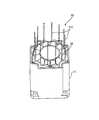
図1は、ステータの組立の途中状態のモータを示した斜視図である。 FIG. 1 is a perspective view showing the motor in a state in which the stator is being assembled.
この図1には、モータ10の外観の一部を構成する筐体11内にステータコイル20を収容した状態が示されている。このステータコイル20は、巻回されたワイヤを有し、そのワイヤの端部211が筐体11からはみ出して上方に延びている。この図1では、ワイヤの端部211は上方に垂直に延びている。ただし、実際は、ワイヤの剛性が低いこと等のためにワイヤの端部211の姿勢が安定せず、ワイヤごとに様々な向きに曲がりながら全体として上方に延びている。 FIG. 1 shows a state in which a
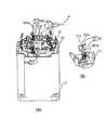
図2は、ステータコイルの上にステータ枠を配置した状態を示した斜視図である。ここで、図2(A)は全体図であり、図2(B)はステータ枠の一部分の拡大図である。 FIG. 2 is a perspective view showing a state where a stator frame is arranged on a stator coil. Here, FIG. 2A is an overall view, and FIG. 2B is an enlarged view of a part of the stator frame.
ステータ枠30は、コネクタ部31と板部32を有する。コネクタ部31は、このモータ10とモータ10の外部の回路との間のコネクタ接続を担っている。板部32は、絶縁樹脂からなり、全体として略板形状かつ略円環形状を有する。このステータ枠30は、板部32の第1面をステータコイル20に向けて、そのステータコイル20に隣接した位置に配置されている。
また、このステータ枠は、ステータコイル20を構成するワイヤの端部211とコネクタ部31とを電気的に接続する導体を備えている。この導体は、板部32にインサート成形されていて、その両端部が現れている。この導体の、コネクタ部31側の端部は、そのコネクタ部31のコンタクト41(図3参照)を構成している。またこの導体の、他方のの端部には、ステータコイル20のワイヤの端部211を圧着する圧着端子42(42a,42b)を備えている。この圧着端子42は、板部32から立設した形状を有し、そこには、オープンバレル型の圧着部421と、仮保持部422が設けられている。圧着部421は、その内面に、ワイヤの被覆を突き破るセレーション421aが形成されており、ステータコイル20のワイヤの端部211の圧着接続を担っている。仮保持部422は、ワイヤの端部211が延びる向き(この図2の上向き)に沿って、圧着部421よりも先端側に設けられている。この仮保持部422には、ワイヤの端部211の、圧着部421に配置される部分よりもさらに先端の部分212が配置され、その先端の部分212を仮保持する役割りを担っている。この仮保持部422は、ふた股に分かれている。そして、そのふた股の間に形成された仮保持溝422aにワイヤの先端の部分212を挟んで引っ掛けることにより、ワイヤの先端の部分212が、仮保持部422に仮保持される。これにより、ワイヤの端部211は、圧着部421のバレル内に安定的に配置される。この仮保持溝422aの幅はワイヤの径の1.1倍から5倍が望ましいが、ワイヤの径とほぼ同じにして仮保持溝422a内のワイヤを圧入してもよい。 In addition, the stator frame includes a conductor that electrically connects the
ここで、圧着部421と仮保持部422とが設けられた圧着端子42には、円環形状の板部32の外周に沿って配置された外周側圧着端子42aと、その円環の内周に沿って配置された内周側圧着端子42bとがある。そして、外周に沿って配置された外周側圧着端子42aの圧着部421は、そのバレルが外向きに開いた圧着部である。一方、内周に沿って配置された内周側圧着端子42bの圧着部421は、そのバレルが内向きに開いた圧着部である。 Here, the
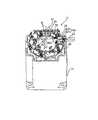
図3は、外周側圧着端子の圧着部によるワイヤの端部の圧着接続の様子を示した斜視図である。 FIG. 3 is a perspective view showing the state of crimping connection of the end of the wire by the crimping portion of the outer peripheral side crimp terminal.
圧着部421のバレルの背の部分にモータ10の中心側からアンビル51をあてがい、ふた股形状のクリンパ52を、モータ10の外側からバレルの開いた側に押し当てることにより、ワイヤの端部211が圧着接続される。 An
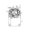
図4は、内周側圧着端子の圧着部によるワイヤの端部の圧着接続の様子を示した斜視図である。 FIG. 4 is a perspective view showing a state of crimping connection of an end portion of a wire by a crimping portion of the inner peripheral side crimp terminal.
この内周側圧着端子42bの圧着部421は、外周側圧着端子42aの圧着部421とは異なり、そのバレルが内向きに開いている。このため、モータ10の外側からバレルの背の部分にアンビル51をあてがい、クリンパ52をバレルの開いた側にモータ10の中心側から押し当てて、ワイヤの端部211を圧着接続する。 Unlike the crimping
これら図3や図4に示す圧着は、ワイヤの先端の部分212が仮保持部422に仮保持された状態で行われるため、ワイヤの端部211が圧着部421に確実に圧着される。 Since the crimping shown in FIGS. 3 and 4 is performed in a state where the
図5は、圧着後の状態を示した斜視図である。ここで、図5(A)は全体図、図5(B),(C)は圧着部分の拡大図である。 FIG. 5 is a perspective view showing a state after crimping. Here, FIG. 5A is an overall view, and FIGS. 5B and 5C are enlarged views of a crimped portion.
図5には、圧着後の圧着部421が示されている。この圧着接続では、外周側圧着端子42aと内周側圧着端子42bのいずれにおいても、圧着部421がワイヤの端部211の絶縁被覆を貫通して、ワイヤと導通している。 FIG. 5 shows the crimping
図6は、仮保持部の切断後の状態を示した斜視図である。ここで、図6(A)は全体図、図6(B)は圧着部の部分を示した拡大図である。 FIG. 6 is a perspective view showing a state after cutting the temporary holding unit. Here, FIG. 6A is an overall view, and FIG. 6B is an enlarged view showing a crimping portion.
仮保持部422は、ワイヤの端部211の圧着時の姿勢を安定化させておくためのものであり、モータの小型化の観点から圧着が終わると不要となる。そこで、ここでは、仮保持部422が切断されて取り除かれる。この切断により、この圧着端子42には、ワイヤの端縁と面一で終端した終端部423が形成される。 The
図7は、折れ曲がり部を形成した後の状態を示した斜視図である。ここで、図7(A)は全体図、図7(B)は折れ曲がり部を示した拡大図である。この折れ曲がり部424は、圧着部421を間に挟んだ、終端部423とは反対側の位置、すなわち、導体の、絶縁樹脂に埋め込まれた部分と圧着部421との間に形成されている。そして、この折れ曲がり部424は、圧着部421がステータ枠30の板部32の第2面(ステータコイル20側を向いた第1面に対する裏面であって図7では上面)に沿うように折れ曲がっている。この折れ曲がり部424を形成したことにより、導体の、筐体11からの突出量を小さくし、モータ10の小型化に寄与している。 FIG. 7 is a perspective view showing a state after a bent portion is formed. Here, FIG. 7A is an overall view, and FIG. 7B is an enlarged view showing a bent portion. The
なお、本実施形態は、ステータ枠30が、円環形状の板部32の外周に沿う外周側圧着端子42aと、内周に沿う内周側圧着端子42bとの双方を有する構造であるが、本発明は、圧着端子42の数や配置位置等を問うものではない。さらに、仮保持部の切断及び折り曲げは必ずしも必要ではない。 The present embodiment has a structure in which the
また、本実施形態は、本発明の圧着端子をモータのステータ枠に適用したものであるが、本発明の圧着端子は、モータに限られず、圧着接続が適用される結線部を有する機器や装置等に広く適用することができる。 Further, in the present embodiment, the crimp terminal of the present invention is applied to a stator frame of a motor. However, the crimp terminal of the present invention is not limited to a motor, and a device or an apparatus having a connection portion to which crimp connection is applied. Etc. can be widely applied.
10 モータ
11 筐体
20 ステータコイル
211 ワイヤの端部
212 ワイヤの先端の部分
30 ステータ枠
31 コネクタ部
32 板部
41 コンタクト
42 圧着端子
42a 外周側圧着端子
42b 内周側圧着端子
421 圧着部
422 仮保持部
423 終端部
424 折れ曲がり部
Claims (3)
Translated fromJapanese前記ワイヤの端部を圧着前の前記圧着部に配置するとともに、該端部の、該圧着部に配置される部分よりもさらに先端の部分を前記仮保持部に配置して該仮保持部に仮保持させ、
前記ワイヤを、前記圧着部が該ワイヤの端部の絶縁被覆を貫通して該ワイヤと導通するように、前記圧着部に圧着することを特徴とするモータのステータ組立方法。It has a connector portion for connecting the connector to the outside, and electrically connects the connector portion to the end of the wire of the stator coil. An open barrel type crimping portion, and a conductor provided with a temporary holding portion for temporarily holding the tip portion, the tip portion being further disposed than the portion arranged in the crimping portion of the end portion is provided. Place the stator frame adjacent to the stator coil,
While arranging the end of the wire in the crimping portion before crimping, the end of the wire is further arranged in the temporary holding portion with a tip portion further than the portion arranged in the crimping portion, and is provided in the temporary holding portion. Temporarily hold
A method of assembling a stator for a motor, wherein the wire is crimped to the crimping portion such that the crimping portion penetrates through an insulating coating at an end of the wire and conducts with the wire.
外部とのコネクタ接続を担うコネクタ部を有するとともに、該コネクタ部と前記ワイヤの端部とを電気的に繋ぐ導体を有するステータ枠とを備え、
前記導体が、
前記ワイヤの端部の絶縁被覆を貫通して該ワイヤと導通した圧着部と、
前記端部の、前記圧着部に配置される部分よりもさらに先端の部分が配置されて該先端の部分を仮保持する仮保持部とを備えたことを特徴とするモータのステータ構造。A stator coil having a wound wire;
A connector frame having a connector portion that carries out connector connection with the outside, and a stator frame having a conductor that electrically connects the connector portion and an end of the wire,
Said conductor,
A crimping portion that penetrates through the insulating coating at the end of the wire and conducts with the wire;
A motor stator structure, comprising: a temporary holding portion that further includes a tip portion of the end portion further disposed than a portion arranged in the crimping portion and temporarily holds the tip portion.
Priority Applications (6)
| Application Number | Priority Date | Filing Date | Title |
|---|---|---|---|
| JP2016110730AJP6674847B2 (en) | 2016-06-02 | 2016-06-02 | Motor stator assembling method and motor stator structure |
| TW106114104ATWI747897B (en) | 2016-06-02 | 2017-04-27 | Stator assembling method for motor and stator structure for motor |
| KR1020170061716AKR102382776B1 (en) | 2016-06-02 | 2017-05-18 | Stator assembling method for motor, stator structure for motor, and crimp terminal |
| DE102017111875.6ADE102017111875A1 (en) | 2016-06-02 | 2017-05-31 | Stator mounting method for a motor, stator structure for a motor and crimping terminal |
| US15/609,716US10862379B2 (en) | 2016-06-02 | 2017-05-31 | Stator assembling method for motor, stator structure for motor, and crimp terminal |
| CN201710408774.1ACN107465313B (en) | 2016-06-02 | 2017-06-02 | Motor stator assembling method, motor stator structure, and crimp terminal |
Applications Claiming Priority (1)
| Application Number | Priority Date | Filing Date | Title |
|---|---|---|---|
| JP2016110730AJP6674847B2 (en) | 2016-06-02 | 2016-06-02 | Motor stator assembling method and motor stator structure |
Publications (2)
| Publication Number | Publication Date |
|---|---|
| JP2017216851A JP2017216851A (en) | 2017-12-07 |
| JP6674847B2true JP6674847B2 (en) | 2020-04-01 |
Family
ID=60327969
Family Applications (1)
| Application Number | Title | Priority Date | Filing Date |
|---|---|---|---|
| JP2016110730AActiveJP6674847B2 (en) | 2016-06-02 | 2016-06-02 | Motor stator assembling method and motor stator structure |
Country Status (6)
| Country | Link |
|---|---|
| US (1) | US10862379B2 (en) |
| JP (1) | JP6674847B2 (en) |
| KR (1) | KR102382776B1 (en) |
| CN (1) | CN107465313B (en) |
| DE (1) | DE102017111875A1 (en) |
| TW (1) | TWI747897B (en) |
Families Citing this family (2)
| Publication number | Priority date | Publication date | Assignee | Title |
|---|---|---|---|---|
| DE102018102976A1 (en)* | 2018-02-09 | 2019-08-14 | Nidec Corp. | wire holder |
| DE102023205469A1 (en)* | 2023-06-13 | 2024-12-19 | Brose Fahrzeugteile SE & Co. Kommanditgesellschaft, Würzburg | Contact device for a stator of an electric motor |
Family Cites Families (18)
| Publication number | Priority date | Publication date | Assignee | Title |
|---|---|---|---|---|
| US3963857A (en)* | 1974-09-12 | 1976-06-15 | Amp Incorporated | Small magnet wire to lead wire termination |
| JPS62201012A (en)* | 1986-02-26 | 1987-09-04 | 株式会社東芝 | Safety device for gas insulated switchgear |
| JPS62201032A (en)* | 1986-02-27 | 1987-09-04 | Nippon Denso Co Ltd | Supporting mechanism of lead-out portion of winding for motor |
| JPS6379058U (en)* | 1986-11-11 | 1988-05-25 | ||
| JP2001229988A (en)* | 2000-02-21 | 2001-08-24 | Yazaki Corp | ID terminal |
| JP2003023759A (en)* | 2001-07-04 | 2003-01-24 | Denso Corp | AC generator for vehicles |
| US6736664B2 (en)* | 2001-07-06 | 2004-05-18 | Yazaki Corporation | Piercing terminal and machine and method for crimping piercing terminal |
| JP3977138B2 (en) | 2002-05-13 | 2007-09-19 | 本田技研工業株式会社 | Rotating electric machine |
| JP3938542B2 (en)* | 2002-11-12 | 2007-06-27 | タイコエレクトロニクスアンプ株式会社 | Pressure welding device |
| TW200501521A (en)* | 2003-04-16 | 2005-01-01 | J S T Mfg Co Ltd | Electric coupler and housing of plug-type connector |
| US7645286B2 (en)* | 2005-05-20 | 2010-01-12 | Neotract, Inc. | Devices, systems and methods for retracting, lifting, compressing, supporting or repositioning tissues or anatomical structures |
| JP5097606B2 (en)* | 2008-04-24 | 2012-12-12 | 東北電力株式会社 | Covered through-type compression connector |
| JP5282527B2 (en)* | 2008-10-31 | 2013-09-04 | アイシン精機株式会社 | Motor coil wiring components |
| JP4645765B1 (en)* | 2009-12-24 | 2011-03-09 | トヨタ自動車株式会社 | Motor rotor and motor rotor manufacturing method |
| JP5835340B2 (en)* | 2011-10-14 | 2015-12-24 | オムロン株式会社 | Plate terminal |
| JP6185826B2 (en) | 2013-11-27 | 2017-08-23 | タイコエレクトロニクスジャパン合同会社 | Motor connector and motor connector assembly |
| JP2015104284A (en)* | 2013-11-27 | 2015-06-04 | タイコエレクトロニクスジャパン合同会社 | Stator frame for motor |
| JP6373077B2 (en)* | 2014-06-12 | 2018-08-15 | 古河電気工業株式会社 | Electric wire with crimp terminal |
- 2016
- 2016-06-02JPJP2016110730Apatent/JP6674847B2/enactiveActive
- 2017
- 2017-04-27TWTW106114104Apatent/TWI747897B/enactive
- 2017-05-18KRKR1020170061716Apatent/KR102382776B1/enactiveActive
- 2017-05-31DEDE102017111875.6Apatent/DE102017111875A1/enactivePending
- 2017-05-31USUS15/609,716patent/US10862379B2/enactiveActive
- 2017-06-02CNCN201710408774.1Apatent/CN107465313B/enactiveActive
Also Published As
| Publication number | Publication date |
|---|---|
| US20170353088A1 (en) | 2017-12-07 |
| KR102382776B1 (en) | 2022-04-04 |
| CN107465313A (en) | 2017-12-12 |
| TW201743539A (en) | 2017-12-16 |
| TWI747897B (en) | 2021-12-01 |
| DE102017111875A1 (en) | 2017-12-07 |
| JP2017216851A (en) | 2017-12-07 |
| CN107465313B (en) | 2021-08-10 |
| KR20170136979A (en) | 2017-12-12 |
| US10862379B2 (en) | 2020-12-08 |
Similar Documents
| Publication | Publication Date | Title |
|---|---|---|
| WO2009113686A1 (en) | Hoop material, method for manufacturing inner conductor terminal, and coaxial connector | |
| JP2013004347A (en) | Shield connector | |
| JP2013196832A (en) | Wire with crimp-terminal | |
| JP5195244B2 (en) | Terminal fittings and electric wires with terminal fittings | |
| JP2014110673A (en) | Power line connection structure of stator | |
| JPWO2013146640A1 (en) | Electric wire with terminal | |
| US20140353361A1 (en) | Electric wire connecting method and connecting device thereof | |
| JP4666650B2 (en) | Manufacturing method of electric wire with terminal and electric wire with terminal | |
| JP6674847B2 (en) | Motor stator assembling method and motor stator structure | |
| JP5798840B2 (en) | Connecting terminal | |
| WO2017195547A1 (en) | Terminal-equipped electric wire, and terminal | |
| JP4051069B2 (en) | Connector for coaxial cable | |
| JP6786312B2 (en) | Crimping terminal | |
| TWI651905B (en) | Wire connector | |
| JPH097649A (en) | Crimp contact | |
| KR102428329B1 (en) | Thermal protector | |
| JP4381959B2 (en) | Wire harness joint connector and manufacturing method thereof | |
| JP2006294572A (en) | Coaxial cable electrical connector | |
| JP2010129448A (en) | Terminal fitting | |
| JP5594816B2 (en) | Crimping terminal and crimping device | |
| JP5195191B2 (en) | Terminal fittings and electric wires with terminal fittings | |
| JP2016201331A (en) | Manufacturing method of wire with connector and wire with connector | |
| JP5074270B2 (en) | Terminal fitting and wire harness | |
| JP2004179150A (en) | Coaxial cable connector | |
| JPS6212343A (en) | Terminal block for terminating stator winding or motor |
Legal Events
| Date | Code | Title | Description |
|---|---|---|---|
| A621 | Written request for application examination | Free format text:JAPANESE INTERMEDIATE CODE: A621 Effective date:20190207 | |
| A977 | Report on retrieval | Free format text:JAPANESE INTERMEDIATE CODE: A971007 Effective date:20191016 | |
| A131 | Notification of reasons for refusal | Free format text:JAPANESE INTERMEDIATE CODE: A131 Effective date:20191023 | |
| A521 | Request for written amendment filed | Free format text:JAPANESE INTERMEDIATE CODE: A523 Effective date:20191204 | |
| TRDD | Decision of grant or rejection written | ||
| A01 | Written decision to grant a patent or to grant a registration (utility model) | Free format text:JAPANESE INTERMEDIATE CODE: A01 Effective date:20200213 | |
| A61 | First payment of annual fees (during grant procedure) | Free format text:JAPANESE INTERMEDIATE CODE: A61 Effective date:20200309 | |
| R150 | Certificate of patent or registration of utility model | Ref document number:6674847 Country of ref document:JP Free format text:JAPANESE INTERMEDIATE CODE: R150 | |
| R250 | Receipt of annual fees | Free format text:JAPANESE INTERMEDIATE CODE: R250 | |
| R250 | Receipt of annual fees | Free format text:JAPANESE INTERMEDIATE CODE: R250 | |
| R250 | Receipt of annual fees | Free format text:JAPANESE INTERMEDIATE CODE: R250 |