JP6674257B2 - Structure of Touchpad Using Dummy Pattern for Capacitive Touch Screen - Google Patents
Structure of Touchpad Using Dummy Pattern for Capacitive Touch ScreenDownload PDFInfo
- Publication number
- JP6674257B2 JP6674257B2JP2015560101AJP2015560101AJP6674257B2JP 6674257 B2JP6674257 B2JP 6674257B2JP 2015560101 AJP2015560101 AJP 2015560101AJP 2015560101 AJP2015560101 AJP 2015560101AJP 6674257 B2JP6674257 B2JP 6674257B2
- Authority
- JP
- Japan
- Prior art keywords
- pattern
- dummy pattern
- dummy
- sensor
- patterns
- Prior art date
- Legal status (The legal status is an assumption and is not a legal conclusion. Google has not performed a legal analysis and makes no representation as to the accuracy of the status listed.)
- Active
Links
Images


Classifications
- G—PHYSICS
- G06—COMPUTING OR CALCULATING; COUNTING
- G06F—ELECTRIC DIGITAL DATA PROCESSING
- G06F3/00—Input arrangements for transferring data to be processed into a form capable of being handled by the computer; Output arrangements for transferring data from processing unit to output unit, e.g. interface arrangements
- G06F3/01—Input arrangements or combined input and output arrangements for interaction between user and computer
- G06F3/03—Arrangements for converting the position or the displacement of a member into a coded form
- G06F3/041—Digitisers, e.g. for touch screens or touch pads, characterised by the transducing means
- G06F3/044—Digitisers, e.g. for touch screens or touch pads, characterised by the transducing means by capacitive means
- G—PHYSICS
- G06—COMPUTING OR CALCULATING; COUNTING
- G06F—ELECTRIC DIGITAL DATA PROCESSING
- G06F2203/00—Indexing scheme relating to G06F3/00 - G06F3/048
- G06F2203/041—Indexing scheme relating to G06F3/041 - G06F3/045
- G06F2203/04103—Manufacturing, i.e. details related to manufacturing processes specially suited for touch sensitive devices
- G—PHYSICS
- G06—COMPUTING OR CALCULATING; COUNTING
- G06F—ELECTRIC DIGITAL DATA PROCESSING
- G06F2203/00—Indexing scheme relating to G06F3/00 - G06F3/048
- G06F2203/041—Indexing scheme relating to G06F3/041 - G06F3/045
- G06F2203/04111—Cross over in capacitive digitiser, i.e. details of structures for connecting electrodes of the sensing pattern where the connections cross each other, e.g. bridge structures comprising an insulating layer, or vias through substrate
Landscapes
- Engineering & Computer Science (AREA)
- General Engineering & Computer Science (AREA)
- Theoretical Computer Science (AREA)
- Human Computer Interaction (AREA)
- Physics & Mathematics (AREA)
- General Physics & Mathematics (AREA)
- Position Input By Displaying (AREA)
Description
Translated fromJapanese本発明は、静電容量式タッチスクリーンのためのタッチパッドの構造に関し、より詳細には、静電容量式タッチスクリーンのためのダミーパターンを使用するタッチパッドの構造に関する。 The present invention relates to a touch pad structure for a capacitive touch screen, and more particularly, to a touch pad structure using a dummy pattern for a capacitive touch screen.
近年、携帯電話、PDA、MP3プレーヤなどの多様な携帯端末は、携帯性を向上させるためにそのサイズが小型化している。一方、このような携帯端末を利用して優れた品質の映像を提供するために、これに適用するディスプレイは大型化している。携帯端末自体の小型化とこれに適用するディスプレイの大型化の要求を満たすために、ディスプレイ自体にユーザの入力を可能にするタッチスクリーン方式が主に採用されている。また、LCD(Liquid Crystal Display)、PDP(Plasma Display Panel)、OLED(Organic Light Emitting Diode)、AMOLED(Active Matrix Organic Light Emitting Diode)などの大型TVやモニタでも、タッチスクリーン方式が採用されている。 In recent years, various mobile terminals such as mobile phones, PDAs, and MP3 players have been reduced in size in order to improve portability. On the other hand, in order to provide an excellent quality image using such a mobile terminal, a display applied to the mobile terminal has been increased in size. In order to satisfy the demands for downsizing the mobile terminal itself and increasing the size of the display applied to the mobile terminal, a touch screen method that enables a user to input the display itself is mainly used. In addition, LCD (Liquid Crystal Display), PDP (Plasma Display Panel), OLED (Organic Light Emitting Diode), AMOLED (Active Matrix Organic Lighting, etc., which is used for Active Matrix and Light Emitting) are also used for the monitor.
このようなタッチスクリーンは、ユーザがスクリーンに直接表示される文字や特定の位置に人間の手やタッチペンが触れた場合、触れた位置の座標を把握することによってユーザの入力を可能にする装置である。このようなタッチスクリーンは、その動作原理に応じ、静電容量方式、抵抗膜方式、表面超音波方式、赤外線方式などがある。 Such a touch screen is a device that enables a user to input by grasping the coordinates of the touched position when a human hand or a touch pen touches a character or a specific position displayed directly on the screen. is there. Such touch screens include a capacitance type, a resistive type, a surface ultrasonic type, an infrared type, and the like according to the operation principle.
特に、静電容量方式のタッチスクリーンは、人間の手または物体が触れたとき、導電性センサパターンが周辺の他のセンサパターンまたは接地電極などと形成する静電容量の変化を感知することによって接触位置を電気的信号に変換するようになる。 In particular, the touch screen of the capacitance type touches a human hand or an object by sensing a change in capacitance formed by the conductive sensor pattern with other sensor patterns or a ground electrode, etc., in the vicinity. The position is converted into an electric signal.
このとき、接触面の接触位置を明確に判断するために、センサパターンは、第1方向に沿って連結するように形成された第1センサパターン、またはX方向パターンと第2方向に沿って連結するように形成された第2センサパターン、またはY方向パターンを含んで構成されるようになる。 At this time, in order to clearly determine the contact position of the contact surface, the sensor pattern is connected along the second direction with the first sensor pattern formed so as to be connected along the first direction or the X direction pattern. The second sensor pattern or the Y-direction pattern is formed so as to be formed.
第1センサパターンと第2センサパターンは、それぞれ互いに異なるレイヤに配置される。例えば、第1センサパターンは上部レイヤに位置し、第2センサパターンは下部レイヤに位置し、第1センサパターンの間と第2センサパターンの間にはダミーパターンが配置される。 The first sensor pattern and the second sensor pattern are respectively arranged on different layers. For example, the first sensor pattern is located on the upper layer, the second sensor pattern is located on the lower layer, and a dummy pattern is arranged between the first sensor pattern and the second sensor pattern.
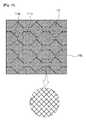
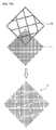
図1a〜図1bは、従来技術に係るセンサパターンとダミーパターンの配置形態を示した図である。 FIGS. 1A and 1B are views showing the arrangement of a sensor pattern and a dummy pattern according to the related art.
図1aを参照すると、従来技術に係るタッチパッド内のセンサパターン110の間にダミーパターン111が配置されており、ダミーパターンは互いに連結していないことが確認される。センサパターンとダミーパターン間の部分短絡時に、センサパターンから電流が1つのダミーパターンに流入する。 Referring to FIG. 1A, a
図1bを参照すると、従来技術に係るタッチパッド内のセンサパターン110の間にダミーパターン111aが配置されており、ダミーパターンも互いに連結していることが確認される(111b)。センサパターンとダミーパターン間の部分短絡時に、センサパターンから電流がダミーパターン全体に流入する。 Referring to FIG. 1B, it is confirmed that the
図2a〜図2bは、タッチパネル内の短絡による誤動作を説明するための図である。 2A and 2B are diagrams for explaining a malfunction due to a short circuit in the touch panel.
図2aを参照すると、タッチパッド内のセンサパターンの特定部位をタッチすると、この部分の静電容量の変化をX軸とY軸に連結するそれぞれのセンサで認識してタッチ座標を把握することができる。 Referring to FIG. 2A, when a specific part of the sensor pattern in the touch pad is touched, a change in the capacitance of this part is recognized by each sensor connected to the X axis and the Y axis, and the touch coordinates can be grasped. it can.
図2bを参照すると、センサパターンとダミーパターン間の部分短絡が発生した場合、センサパターンの特定部位がタッチされると、電流がセンサパターンからダミーパターンに流入する。 Referring to FIG. 2B, when a partial short circuit occurs between the sensor pattern and the dummy pattern, a current flows from the sensor pattern to the dummy pattern when a specific portion of the sensor pattern is touched.
特に、ダミーパターンが互いに連結していない場合よりもダミーパターンが互いに連結している場合に、センサパターンとダミーパターン間の部分短絡が発生すると、センサパターンから流入した電流がダミーパターン全体に流入するため、過度な静電容量の変化を招来するようになり、正確な接触位置を判断するための妨害要素として作用するようになる。 In particular, when a partial short circuit occurs between the sensor pattern and the dummy pattern when the dummy patterns are connected to each other rather than when the dummy patterns are not connected to each other, the current flowing from the sensor pattern flows into the entire dummy pattern. As a result, an excessive change in the capacitance is caused, which acts as an obstructive element for determining an accurate contact position.
したがって、このような従来技術の問題点を解決するために、本発明は、センサパターンの間にダミーパターンを配置し、配置するダミーパターンを多数の予め設定された形態に分割して形成する、静電容量式タッチスクリーンのためのダミーパターンを使用するタッチパッドの構造を提供することを目的とする。 Therefore, in order to solve the problems of the related art, the present invention arranges a dummy pattern between sensor patterns, and forms the dummy pattern to be arranged by dividing the dummy pattern into a number of preset forms. An object of the present invention is to provide a structure of a touch pad using a dummy pattern for a capacitive touch screen.
また、本発明は、センサパターンの間にダミーパターンを配置し、配置するダミーパターンを構成するメッシュを規則的または不規則的に断線させて形成する、静電容量式タッチスクリーンのためのダミーパターンを使用するタッチパッドの構造を提供することを他の目的とする。 Further, the present invention provides a dummy pattern for a capacitive touch screen, in which a dummy pattern is arranged between sensor patterns, and meshes constituting the arranged dummy pattern are formed by regularly or irregularly breaking. Another object of the present invention is to provide a structure of a touch pad using the touch pad.
なお、本発明は、センサパターンの間にダミーパターンを配置し、センサパターンとダミーパターンの間に位置し、センサパターンとダミーパターン間の境界面に沿って予め設定された距離だけ離隔して物理的に分離する補助ダミーパターンを形成する、静電容量式タッチスクリーンのためのダミーパターンを使用するタッチパッドの構造を提供することをさらに他の目的とする。 According to the present invention, a dummy pattern is arranged between the sensor patterns, the dummy pattern is located between the sensor pattern and the dummy pattern, and is physically separated by a predetermined distance along a boundary surface between the sensor pattern and the dummy pattern. It is still another object of the present invention to provide a touch pad structure using a dummy pattern for a capacitive touch screen, which forms an auxiliary dummy pattern that is electrically separated.
しかし、発明の目的が上述した事項に制限されるものではなく、上述されていないさらに他の目的は、後述の記載から当業者によって明確に理解されるであろう。 However, the purpose of the invention is not limited to the above-mentioned items, and other objects not described above will be clearly understood by those skilled in the art from the following description.
上述した目的を達成するために、本発明の一観点に係る静電容量式タッチスクリーンのためのダミーパターンを使用するタッチパッドの構造は、第1方向に形成された第1センサパターンと前記第1センサパターンの間に第1ダミーパターンが配列される第1センサ部、および前記第1センサ部と重なっており、前記第1方向と交差する第2方向に形成された第2センサパターンと前記第2センサパターンの間に第2ダミーパターンが配列される第2センサ部を備え、前記第1ダミーパターンと前記第2ダミーパターンそれぞれは、物理的に分離する少なくとも2つ以上のサブダミーパターンからなることを特徴とする。 In order to achieve the above object, a touch pad structure using a dummy pattern for a capacitive touch screen according to an aspect of the present invention includes a first sensor pattern formed in a first direction and the first sensor pattern. A first sensor portion in which a first dummy pattern is arranged between one sensor pattern; and a second sensor pattern overlapping with the first sensor portion and formed in a second direction intersecting the first direction. A second sensor portion in which a second dummy pattern is arranged between the second sensor patterns, wherein each of the first dummy pattern and the second dummy pattern is separated from at least two or more sub-dummy patterns physically separated; It is characterized by becoming.
好ましくは、前記第1ダミーパターンは前記第2センサパターンの位置に対応する領域に配置され、前記第2ダミーパターンは前記第1センサパターンの位置に対応する領域に配置されることを特徴とする。 Preferably, the first dummy pattern is disposed in a region corresponding to the position of the second sensor pattern, and the second dummy pattern is disposed in a region corresponding to the position of the first sensor pattern. .
好ましくは、前記第1ダミーパターンと前記第2ダミーパターンそれぞれは、少なくとも2つ以上のサブダミーパターンからなり、互いに異なる数のサブダミーパターンからなることを特徴とする。 Preferably, each of the first dummy pattern and the second dummy pattern includes at least two or more sub-dummy patterns, and includes a different number of sub-dummy patterns.
好ましくは、分離した前記少なくとも2つ以上のサブダミーパターンそれぞれの境界線は、当該ダミーパターンを構成するメッシュの方向と互いに平行するように形成されることを特徴とする。 Preferably, a boundary line of each of the separated at least two or more sub-dummy patterns is formed so as to be parallel to a direction of a mesh forming the dummy pattern.
好ましくは、分離した前記少なくとも2つ以上のサブダミーパターンそれぞれの境界線は、当該ダミーパターンを構成するメッシュの方向と互いに平行しないように形成されることを特徴とする。 Preferably, a boundary line of each of the separated at least two or more sub-dummy patterns is formed so as not to be parallel to a direction of a mesh forming the dummy pattern.
好ましくは、前記第1ダミーパターンと前記第2ダミーパターンそれぞれは、予め設定された形態を有する2つ以上のサブダミーパターンからなり、前記2つ以上のサブダミーパターンそれぞれは、第1ダミーパターンまたは第2ダミーパターンの全体外郭の形状と同じ形状を有して均等面積を有するように形成されることを特徴とする。 Preferably, each of the first dummy pattern and the second dummy pattern includes two or more sub-dummy patterns having a preset form, and each of the two or more sub-dummy patterns includes a first dummy pattern or The second dummy pattern is formed to have the same shape as the entire outer shape and to have an equal area.
好ましくは、前記第1ダミーパターンと前記第2ダミーパターンそれぞれは、予め設定された形態を有する2つ以上のサブダミーパターンからなり、前記2つ以上のサブダミーパターンそれぞれは、第1ダミーパターンまたは第2ダミーパターンの全体外郭の形状とは異なる形状を有するが均等面積を有するように形成されることを特徴とする。 Preferably, each of the first dummy pattern and the second dummy pattern includes two or more sub-dummy patterns having a preset form, and each of the two or more sub-dummy patterns includes a first dummy pattern or The second dummy pattern is formed to have a shape different from the shape of the entire outer periphery but to have an equal area.
好ましくは、前記第1ダミーパターンと前記第2ダミーパターンそれぞれは、予め設定された形態を有する2つ以上のサブダミーパターンからなり、前記2つ以上のサブダミーパターンそれぞれは、第1ダミーパターンまたは第2ダミーパターンの全体外郭の形状とは異なる形状を有して異なる面積を有するように形成されることを特徴とする。 Preferably, each of the first dummy pattern and the second dummy pattern includes two or more sub-dummy patterns having a preset form, and each of the two or more sub-dummy patterns includes a first dummy pattern or The second dummy pattern may be formed to have a shape different from the shape of the entire outer periphery and to have a different area.
好ましくは、前記第1ダミーパターンと前記第2ダミーパターンそれぞれは、その内部のメッシュを規則的または不規則的に断線させて物理的に分離した少なくとも2つ以上のサブダミーパターンからなることを特徴とする。 Preferably, each of the first dummy pattern and the second dummy pattern is formed of at least two or more sub-dummy patterns physically separated by regularly or irregularly breaking the mesh therein. And
好ましくは、前記第1ダミーパターンと前記第2ダミーパターンそれぞれは、メッシュを予め設定された範囲内で規則的に破断して分割することができ、破断した線の長さが等しくなるように形成されることを特徴とする。 Preferably, each of the first dummy pattern and the second dummy pattern can be divided by regularly breaking a mesh within a preset range, and formed such that broken lines have the same length. It is characterized by being performed.
好ましくは、前記第1ダミーパターンと前記第2ダミーパターンそれぞれは、メッシュを予め設定された範囲内で不規則的に破断して分割することができ、破断した線の長さが互いに異なるように形成されることを特徴とする。 Preferably, each of the first dummy pattern and the second dummy pattern can be divided by breaking a mesh irregularly within a preset range, so that broken lines have different lengths from each other. It is characterized by being formed.
また、本発明に係る静電容量式タッチスクリーンのための補助ダミーパターンを使用するタッチパッドの構造は、前記第1センサパターンと前記第1ダミーパターンの間に位置し、前記第1センサパターンと前記第1ダミーパターン間の境界面に沿って離隔して第1ダミーパターンと物理的に分離するように形成される第1補助ダミーパターン、および前記第2センサパターンと前記第2ダミーパターンの間に位置し、前記第2センサパターンと前記第2ダミーパターン間の境界面に沿って離隔して第2ダミーパターンと物理的に分離するように形成される第2補助ダミーパターンをさらに備えることを特徴とする。 The structure of the touch pad using the auxiliary dummy pattern for the capacitive touch screen according to the present invention may be located between the first sensor pattern and the first dummy pattern. A first auxiliary dummy pattern formed so as to be separated from and physically separated from the first dummy pattern along a boundary surface between the first dummy patterns, and between the second sensor pattern and the second dummy pattern. And a second auxiliary dummy pattern formed to be separated along the boundary between the second sensor pattern and the second dummy pattern so as to be physically separated from the second dummy pattern. Features.
本発明の他の一観点に係る静電容量式タッチスクリーンのための補助ダミーパターンを使用するタッチパッドの構造は、第1方向に形成された第1センサパターンと前記第1センサパターンの間に第1ダミーパターンと第1補助ダミーパターンが配列される第1センサ部、および前記第1センサ部と重なっており、前記第1方向と交差する第2方向に形成された第2センサパターンと前記第2センサパターンの間に第2ダミーパターンと第2補助ダミーパターンが配列される第2センサ部を備え、前記第1補助ダミーパターンは、前記第1センサパターンと前記第1ダミーパターンの間に位置し、前記第1補助ダミーパターンは、前記第1センサパターンと前記第1ダミーパターン間の境界面に沿って離隔して物理的に分離するように形成され、前記第2補助ダミーパターンは、前記第2センサパターンと前記第2ダミーパターンの間に位置し、前記第2補助ダミーパターンは、前記第2センサパターンと前記第2ダミーパターン間の境界面に沿って離隔して物理的に分離するように形成されることを特徴とする。 According to another aspect of the present invention, the structure of the touch pad using the auxiliary dummy pattern for the capacitive touch screen includes a first sensor pattern formed in a first direction and the first sensor pattern. A first sensor unit in which a first dummy pattern and a first auxiliary dummy pattern are arranged; and a second sensor pattern overlapping with the first sensor unit and formed in a second direction intersecting the first direction. A second sensor section in which a second dummy pattern and a second auxiliary dummy pattern are arranged between the second sensor patterns, wherein the first auxiliary dummy pattern is provided between the first sensor pattern and the first dummy pattern; The first auxiliary dummy pattern is formed so as to be separated and physically separated along a boundary surface between the first sensor pattern and the first dummy pattern. The second auxiliary dummy pattern is located between the second sensor pattern and the second dummy pattern, and the second auxiliary dummy pattern is located on an interface between the second sensor pattern and the second dummy pattern. It is formed so as to be separated along and physically separated.
好ましくは、前記第1補助ダミーパターンと前記第2補助ダミーパターンそれぞれは、該当する前記第1センサパターンと前記第2センサパターンの外郭線に沿って離隔して形成され、前記第1センサパターンと前記第2センサパターンの外郭線と同一形状を有するように形成されることを特徴とする。 Preferably, each of the first auxiliary dummy pattern and the second auxiliary dummy pattern is formed to be separated along an outline of the corresponding first sensor pattern and the second sensor pattern, and the first auxiliary pattern and the second auxiliary dummy pattern are separated from each other. The second sensor pattern may be formed to have the same shape as an outline of the second sensor pattern.
好ましくは、前記第1補助ダミーパターンと前記第2補助ダミーパターンそれぞれは、前記第1ダミーパターン、前記第2ダミーパターンと物理的に分離するように形成され、前記第1ダミーパターンと前記第2ダミーパターンそれぞれは、ダミー連結部と結合して形成されることを特徴とする。 Preferably, each of the first auxiliary dummy pattern and the second auxiliary dummy pattern is formed so as to be physically separated from the first dummy pattern and the second dummy pattern. Each of the dummy patterns is formed by being connected to the dummy connection part.
好ましくは、前記第1補助ダミーパターンと前記第2補助ダミーパターンそれぞれは、前記第1ダミーパターン、前記第2ダミーパターンと物理的に分離するように形成され、前記第1ダミーパターンと前記第2ダミーパターンそれぞれは、ダミー連結部と物理的に分離して形成されることを特徴とする。 Preferably, each of the first auxiliary dummy pattern and the second auxiliary dummy pattern is formed so as to be physically separated from the first dummy pattern and the second dummy pattern. Each of the dummy patterns is formed so as to be physically separated from the dummy connection portion.
好ましくは、前記第1補助ダミーパターンと前記第2補助ダミーパターンそれぞれは、前記第1ダミーパターン、前記第2ダミーパターンと物理的に分離するように形成され、前記第1ダミーパターンと前記第2ダミーパターンの外郭を囲むように形成されることを特徴とする。 Preferably, each of the first auxiliary dummy pattern and the second auxiliary dummy pattern is formed so as to be physically separated from the first dummy pattern and the second dummy pattern. It is characterized in that it is formed so as to surround the outline of the dummy pattern.
本発明のさらに他の一観点に係る静電容量式タッチスクリーンのためのダミーパターンを使用するタッチパッドの構造は、基板に形成されてタッチ信号を感知する多数のセンサパターン、前記多数のセンサパターンそれぞれに連結して前記タッチ信号を伝達する多数の配線電極、および前記多数のセンサパターンまたは前記多数の配線電極の間の空間に形成される多数のダミーパターンを備え、前記多数のダミーパターンそれぞれは、物理的に分離した2つ以上のサブダミーパターンからなることを特徴とする。 According to still another aspect of the present invention, a touch pad structure using a dummy pattern for a capacitive touch screen includes a plurality of sensor patterns formed on a substrate for sensing a touch signal, and the plurality of sensor patterns. A plurality of wiring electrodes connected to each other to transmit the touch signal; and a plurality of dummy patterns formed in a space between the plurality of sensor patterns or the plurality of wiring electrodes. And two or more physically separated sub-dummy patterns.
好ましくは、前記多数のセンサパターンは、前記基板の一面に第1方向に配置される多数の第1センサパターン、および前記第1センサパターンが配置された同一面に前記第1方向と交差する第2方向に配置される多数の第2センサパターンを備え、前記ダミーパターンは、前記第2センサパターンの間に配置された第1センサパターンに前記配線電極が連結することによって形成された空間に配列されることを特徴とする。 Preferably, the plurality of sensor patterns include a plurality of first sensor patterns arranged in a first direction on one surface of the substrate, and a plurality of first sensor patterns intersecting the first direction on the same surface on which the first sensor patterns are arranged. A plurality of second sensor patterns arranged in two directions, wherein the dummy patterns are arranged in a space formed by connecting the wiring electrodes to the first sensor patterns arranged between the second sensor patterns; It is characterized by being performed.
好ましくは、前記多数のセンサパターンは、前記基板の一面に第1方向に配置される多数の第1センサパターン、および前記基板の他面に第1方向と交差する第2方向に配置される多数の第2センサパターンを備えることを特徴とする。 Preferably, the plurality of sensor patterns are arranged on one surface of the substrate in a first direction, and are arranged on the other surface of the substrate in a second direction intersecting the first direction. The second sensor pattern is provided.
好ましくは、前記多数のダミーパターンは、前記多数のセンサパターンまたは前記多数の配線電極の間に形成された空間の大きさによって大きさが互いに異なるように形成されることを特徴とする。 Preferably, the plurality of dummy patterns are formed to have different sizes depending on the size of the space formed between the plurality of sensor patterns or the plurality of wiring electrodes.
好ましくは、前記多数のダミーパターンそれぞれは、少なくとも2つ以上のサブダミーパターンからなり、互いに異なる数のサブダミーパターンからなることを特徴とする。 Preferably, each of the plurality of dummy patterns includes at least two or more sub-dummy patterns, and includes a different number of sub-dummy patterns.
好ましくは、分離した前記少なくとも2つ以上のサブダミーパターンそれぞれの境界線は、当該ダミーパターンを構成するメッシュの方向と互いに平行するように形成されることを特徴とする。 Preferably, a boundary line of each of the separated at least two or more sub-dummy patterns is formed so as to be parallel to a direction of a mesh forming the dummy pattern.
好ましくは、分離した前記少なくとも2つ以上のサブダミーパターンそれぞれの境界線は、当該ダミーパターンを構成するメッシュの方向と互いに平行しないように形成されることを特徴とする。 Preferably, a boundary line of each of the separated at least two or more sub-dummy patterns is formed so as not to be parallel to a direction of a mesh forming the dummy pattern.
好ましくは、前記多数のダミーパターンそれぞれは、予め設定された形態を有する2つ以上のサブダミーパターンからなり、前記2つ以上のサブダミーパターンそれぞれは、当該ダミーパターンの全体外郭の形状とは異なる形状を有して異なる面積を有するように形成されることを特徴とする。 Preferably, each of the plurality of dummy patterns includes two or more sub-dummy patterns having a predetermined form, and each of the two or more sub-dummy patterns is different from a shape of a whole outer periphery of the dummy pattern. It is characterized in that it is formed to have different shapes and shapes.
好ましくは、前記多数のダミーパターンそれぞれは、その内部のメッシュを規則的または不規則的に断線させて物理的に分離した少なくとも2つ以上のサブダミーパターンからなることを特徴とする。 Preferably, each of the plurality of dummy patterns is formed of at least two or more sub-dummy patterns which are physically separated by regularly or irregularly breaking the mesh therein.
好ましくは、前記多数のダミーパターンそれぞれは、メッシュを予め設定された範囲内で不規則的に破断して分割し、破断した線の長さが互いに異なるように形成されることを特徴とする。 Preferably, each of the plurality of dummy patterns is formed such that a mesh is broken at irregular intervals within a preset range, and the broken lines have different lengths.
本発明のさらに他の一観点に係る静電容量式タッチスクリーンのためのダミーパターンを使用するタッチパッドの構造は、基板に形成されてタッチ信号を感知する多数のセンサパターン、前記多数のセンサパターンそれぞれに連結して前記タッチ信号を伝達する多数の配線電極、前記多数のセンサパターンまたは前記多数の配線電極の間の空間に形成される多数のダミーパターン、および前記多数のセンサパターンと前記多数のダミーパターンの間に形成されたり前記多数の配線電極と前記多数のダミーパターンの間に形成される多数の補助ダミーパターンを備えることができる。 According to still another aspect of the present invention, a touch pad structure using a dummy pattern for a capacitive touch screen includes a plurality of sensor patterns formed on a substrate for sensing a touch signal, and the plurality of sensor patterns. The plurality of wiring electrodes connected to each other to transmit the touch signal, the plurality of sensor patterns or the plurality of dummy patterns formed in a space between the plurality of wiring electrodes, and the plurality of sensor patterns and the plurality of A plurality of auxiliary dummy patterns may be formed between the dummy patterns or between the plurality of wiring electrodes and the plurality of dummy patterns.
好ましくは、前記多数のダミーパターンは、前記多数のセンサパターンまたは前記多数の配線電極の間に形成された空間の大きさにより、大きさが互いに異なるように形成されることを特徴とする。 Preferably, the plurality of dummy patterns are formed to have different sizes depending on the size of the space formed between the plurality of sensor patterns or the plurality of wiring electrodes.
好ましくは、前記多数のダミーパターンと前記多数の補助ダミーパターンそれぞれは、多数に分割されて形成されることを特徴とする。 Preferably, each of the plurality of dummy patterns and the plurality of auxiliary dummy patterns is formed by being divided into a large number.
これにより、本発明は、センサパターンの間にダミーパターンを配置し、配置するダミーパターンを多数の予め設定された形態に分割して形成したり、配置するダミーパターンを構成するメッシュを規則的または不規則的に断線させて形成したり、センサパターンとダミーパターンの間に位置し、センサパターンとダミーパターン間の境界面に沿って予め設定された距離だけ離隔して物理的に分離した補助ダミーパターンを形成したりすることにより、センサパターンとダミーパターン間の部分短絡が発生しても、機能の安全性を確保することができるという効果がある。 Thereby, the present invention arranges a dummy pattern between sensor patterns, divides a dummy pattern to be arranged into a number of predetermined forms, forms a regular pattern, or forms a mesh constituting the dummy pattern to be arranged. Auxiliary dummy that is formed by being disconnected irregularly or physically separated by a predetermined distance along the boundary between the sensor pattern and the dummy pattern and located between the sensor pattern and the dummy pattern By forming a pattern, even if a partial short circuit occurs between the sensor pattern and the dummy pattern, there is an effect that the safety of the function can be ensured.
また、本発明は、ダミーパターンの分割やメッシュの断線によってセンサパターンからダミーパターンに流入する電流を最小化させ、センサの動作を向上させることができる効果がある。 Further, the present invention has the effect of minimizing the current flowing from the sensor pattern into the dummy pattern due to the division of the dummy pattern or the breaking of the mesh, thereby improving the operation of the sensor.
なお、本発明は、センサパターンとダミーパターンが一部短絡しても、その短絡範囲が小さいため、製品自体を廃棄する程度にまで製品使用に問題がないことから、収率を向上させることができる効果がある。 In addition, according to the present invention, even when the sensor pattern and the dummy pattern are partially short-circuited, the short-circuiting range is small, and there is no problem in using the product to the extent that the product itself is discarded. There is an effect that can be done.
以下、本発明の実施形態に係る静電容量式タッチスクリーンのためのダミーパターンを使用するタッチパッドの構造について、添付の図面を参照しながら説明する。本発明に係る動作および作用を理解するために必要な部分を中心に詳しく説明する。 Hereinafter, a structure of a touch pad using a dummy pattern for a capacitive touch screen according to an embodiment of the present invention will be described with reference to the accompanying drawings. A detailed description will be given focusing on parts necessary for understanding the operation and operation according to the present invention.
また、本発明の構成要素を説明するにおいて、同じ名称の構成要素であっても図面によって異なる参照符号を付与することもあり、互いに異なる図面であっても同じ参照符号を付与することもある。しかし、このような場合であっても、該当する構成要素が実施形態によって互いに異なる機能を有することを意味したり、互いに異なる実施形態で同じ機能を有することを意味するのではなく、それぞれの構成要素の機能は、該当する実施形態でそれぞれの構成要素に関する説明に基づいて判断されなければならない。 Further, in describing the components of the present invention, different components may be given the same reference numerals depending on the drawings, even if the components have the same name, or the same reference symbols may be given even on different drawings. However, even in such a case, it does not mean that the corresponding components have different functions depending on the embodiments, or that the corresponding components have the same functions in different embodiments. The function of the element must be determined based on the description of each component in the corresponding embodiment.
特に、本発明では、センサパターンの間にダミーパターンを配置し、1)配置されるダミーパターンを多数の予め設定された形態を有する多数のサブダミーパターンに分割して形成したり、2)配置されるダミーパターンを構成する内部のメッシュを規則的または不規則的に断線させて形成したり、3)センサパターンとダミーパターンの間に位置し、センサパターンとダミーパターン間の境界面に沿って予め設定された距離だけ離隔して物理的に分離した補助ダミーパターンを形成するようにする、新たなタッチパッドまたはセンサ基板の構造を提案する。 In particular, in the present invention, a dummy pattern is arranged between sensor patterns, and 1) the arranged dummy pattern is divided into a large number of sub-dummy patterns having a predetermined form, and 2) the dummy pattern is formed. And 3) positioned between the sensor pattern and the dummy pattern and along the boundary between the sensor pattern and the dummy pattern. A new touch pad or sensor substrate structure is proposed to form physically separated auxiliary dummy patterns separated by a predetermined distance.
このようにセンサパターンの間に配置されるダミーパターンをサブダミーパターンで分割したり、ダミーパターンと補助ダミーパターンに分割する理由は、短絡時にセンサパターンから流入する電流がダミーパターン全体に流入することを防ぐためである。 The reason why the dummy pattern arranged between the sensor patterns is divided by the sub dummy pattern or the dummy pattern and the auxiliary dummy pattern is that the current flowing from the sensor pattern at the time of short circuit flows into the entire dummy pattern. It is to prevent.
図3は、本発明の一実施形態に係るセンサパターンの形態を示した図である。 FIG. 3 is a diagram showing a form of a sensor pattern according to an embodiment of the present invention.
図3に示すように、本発明に係るセンサパターンは互いに交差配列し、X座標を感知するための第1センサパターン110とY座標を感知するための第2センサパターン210を備えることができる。 As shown in FIG. 3, the sensor patterns according to the present invention may include a
例えば、第1センサパターン110は、X座標を感知するためのパターンであって、第1方向、例えば縦方向に規則的に形成することができる。また、第2センサパターン210は、Y座標を感知するためのパターンであって、第2方向、例えば横方向に規則的に形成することができる。 For example, the
第1センサパターン110は、多数の第1感知部110aと、その第1感知部110aを連結する連結部110bを備え、第2センサパターン210も同じように、多数の第2感知部210aと、その第2感知部210aを連結する連結部210bを備えることができる。 The
図4a〜図4cは、本実施形態に係るタッチスクリーンセンサ基板の感知部と連結部を示した例示図である。 4A to 4C are exemplary views illustrating a sensing unit and a connection unit of the touch screen sensor substrate according to the present embodiment.
図4aを参照すると、本実施形態に係るタッチスクリーンセンサ基板は、基材の一面に一定方向のパターンで連結する電極で形成された多数の感知部110a、および前記パターンの方向と同一または類似する方向のパターンで連結する電極で形成され、前記感知部110aを連結する連結部110bを備える。 Referring to FIG. 4A, the touch screen sensor substrate according to the present embodiment includes a plurality of
また、図4bを参照すると、本実施形態において、タッチスクリーンセンサ基板は、感知部110aに隣接し、前記パターンの方向と同一または類似する方向のパターンで連結する電極で形成され、前記感知部110aの視認性を低減させる多数のダミーパターン111aを使用するようになる。 Referring to FIG. 4B, in this embodiment, the touch screen sensor substrate is formed of electrodes adjacent to the
ここで、感知部110aおよびダミーパターンは、ユーザのタッチ信号を感知するために備えられる電極であって、本発明では導電性材料で形成され、この導電性材料は不透明性を有することができる。 Here, the
また、ダミーパターン111aは、感知部110aと隣り合い、または隣接して形成される電極であって、名称で意味するようにダミー(dummy)、すなわち、感知部110aと類似する形状のパターンで形成され、ユーザのタッチ信号を感知することができないように不活性状態に形成される電極またはその組み合わせを意味する。したがって、感知部110aとダミーパターン111aは、電気的に絶縁するように形成される。ダミーパターン111aを基材に形成する理由は、透明電極物質で形成されない感知部110aがタッチスクリーンセンサに全面に形成され、タッチスクリーンセンサに照射する外部光によって感知部110aが視認される現象を防ぐためである。 Further, the
また、図4a〜図4bの場合には、感知部110aとダミーパターン111aが直線形状に形成されたものが示されているが、本発明がこれに限定されるものではなく、多様なパターンの形状で形成することが可能であり、例えば、感知部110aの全体形状をダイヤモンド、台形、ひし形などの形状で形成することが可能である。 4A and 4B, the
一方、電極は、感知部110aで感知されたタッチ信号を外部の駆動回路(図示せず)に送るために備えられる電極であって、基材に感知部110aおよびダミーパターン111を形成するときに同時に形成されることが好ましい。本発明では、電極に関する事項は発明の範疇を超えるため、これに関するさらに詳細な説明は省略する。 On the other hand, the electrode is an electrode provided for transmitting a touch signal sensed by the
また、図4cを参照すると、本実施形態に係るタッチスクリーンセンサ基板の感知部110a、ダミーパターン111a、および感知連結部110bは、互いに同一または類似する一定方向のパターンで連結する電極で形成されることが好ましい。また、ダミー連結部が備えられる場合には、ダミー連結部も互いに同一または類似する一定方向のパターンで連結する電極で形成されることが好ましい。 Referring to FIG. 4C, the
本実施形態において、一定方向のパターンとは、連続性のあるパターンであって、本実施形態では、図3に示すように、前記一定方向に形成された線が相互交差するメッシュ形状のパターンであることが好ましい。 In the present embodiment, the pattern in a certain direction is a pattern having continuity, and in this embodiment, as shown in FIG. 3, a pattern in a mesh shape in which lines formed in the certain direction cross each other. Preferably, there is.
本実施形態において、パターンが同一または類似するとは、パターンの繰り返しにおいて、その繰り返し周期および繰り返される形態が幾何学的に同じであるだけでなく、その繰り返し周期と繰り返される形態がソフトウェア的に予め決められた容認可能な誤差範囲内で形成される場合を含むことが好ましい。したがって、本実施形態では、感知部110aとダミーパターン111aの電極パターンだけではなく、これらを連結する感知連結部110bおよびダミー連結部111bが存在する場合には、ダミー連結部111bの電極パターンが等しくなるようにすることにより、ユーザによって感知部110aが認識される視認性を減少させることができる。 In the present embodiment, the pattern being the same or similar means that, in the repetition of the pattern, not only the repetition cycle and the repetition form are geometrically the same, but also the repetition cycle and the repetition form are predetermined by software. It is preferable to include the case where it is formed within a given acceptable error range. Therefore, in the present embodiment, if not only the electrode patterns of the
また、前記一定方向のパターンは連続性のあるパターンで形成され、前記パターンの一部を切って前記感知部110aと前記ダミーパターン111aを形成することが好ましい。また、前記パターンの一部が切れたものは、感知部110a、前記ダミーパターン111a、および前記感知連結部110b、およびダミー連結部111bが存在する場合には、ダミー連結部111bの前記パターンの端を開放して形成することが好ましい。 Preferably, the pattern in the certain direction is formed as a continuous pattern, and the
上述したように、感知部110aとダミーパターン111aの境界でパターンの一部が切れていることは、前記感知部110aと前記ダミーパターン111aが電気的に互いに絶縁するためであり、また切れていることによって前記感知部110aと前記ダミーパターン111aのパターンの端を開放して形成することは、図5のように端が枠電極に連結しないことを意味する。図5は図4bの一部を拡大したものであって、図5を参照すると、端を開放することによって枠電極に連結するため連続性が消え、断絶したように見える問題を解決し、実際には微細な間隔で離れてはいるが、全体的に見たときには電極をユーザが連続したものと認識するようなり、感知部110aの視認性を減少させることができる。 As described above, the fact that a part of the pattern is cut off at the boundary between the
本実施形態において、前記パターンは、図4a〜図4cに示すように、一定方向に形成された線が相互交差するメッシュ形状のパターンであることが好ましい。本発明において、メッシュ形状は、整形メッシュ形状と非整形メッシュ形状をすべて含むことができる。一定方向に形成された線が相互交差するメッシュ形状とは、全体的に網状型または網型のメッシュ形状のパターンを形成することを意味する。 In the present embodiment, as shown in FIGS. 4A to 4C, the pattern is preferably a mesh-shaped pattern in which lines formed in a certain direction cross each other. In the present invention, the mesh shape can include both the shaped mesh shape and the non-shaped mesh shape. The mesh shape in which the lines formed in a certain direction cross each other means that a net-like or mesh-like pattern is formed as a whole.
また、パターンの相互交差するメッシュ形状の線は、線幅および前記線間の間隔を定義するピッチ(pitch)が同じであるか、または予め設定された類似度の線幅またはピッチを有することが好ましい。本実施形態において、線幅またはピッチが同じであるか、または予め設定された類似度の線幅またはピッチを有するとは、予め定められた充填率(Fill Factor)が得られるように表1に表示された一定範囲の値を有することを意味する。 In addition, the mesh-shaped lines intersecting each other in the pattern may have the same line width and a pitch defining a space between the lines, or have a predetermined similarity line width or pitch. preferable. In the present embodiment, the fact that the line width or the pitch is the same, or that the line width or the pitch has a preset similarity is defined in Table 1 so that a predetermined filling factor (Fill Factor) is obtained. It has the indicated range of values.

また、本実施形態において相互交差するメッシュ形状の線は、予め決められた角度によってティルティング(tilting)することが好ましい。図6を参照すると、本実施形態において形成される線は、水平軸を基準に45゜傾けた形態のパターンを有し、傾いた形態を有することは、単位面積あたりのタッチ入力を感知するための電極の比率を高めて感知の正確度を高めるためであり、ティルティングする予め決められた角は、一定方向のパターンと前記パターンと異なるパターンの相互干渉によるモアレ現状の発生を防ぐために決められた角度であることが好ましい。本実施形態においてパターンと異なるパターンの干渉とは、それぞれ異なる方向のタッチ位置を感知する複数の基板が積層するにおいて、基板に形成された電極のパターンが干渉を引き起こすことであってもよく、または映像情報を表示する映像情報表示部に含まれた複数の画素が形成するパターンと発生するものであってもよい。 Further, in the present embodiment, it is preferable that the mesh-shaped lines that intersect each other are tilted at a predetermined angle. Referring to FIG. 6, the line formed in the present embodiment has a pattern inclined at 45 ° with respect to the horizontal axis, and having the inclined form senses a touch input per unit area. In order to increase the accuracy of sensing by increasing the ratio of the electrodes, a predetermined angle for tilting is determined in order to prevent the occurrence of a moire current due to mutual interference between a pattern in a certain direction and a pattern different from the pattern. It is preferable that the angle is set at an angle. In the present embodiment, the interference of a pattern different from the pattern may be that when a plurality of substrates that sense touch positions in different directions are stacked, a pattern of an electrode formed on the substrate causes interference, or The pattern may be a pattern formed by a plurality of pixels included in a video information display unit that displays video information.
モアレ現象とは、一般的に、独立する2つの周期的なパターンが一定角度に積層した場合に形成される自然的な干渉現象(interference phenomenon)である。モアレパターンとは、波形態の曲線(wave)、波紋(ripple)、スクリーンの表示映像と積層するように見える小さな束(wisp)形態の強度変動などを意味する。 The moire phenomenon is generally a natural interference phenomenon (interference phenomenon) formed when two independent periodic patterns are stacked at a certain angle. The moiré pattern refers to a wave-like curve, a ripple, a small wisp-like intensity variation that appears to be superimposed on a display image on a screen, and the like.
図7a〜図7cは、本発明の一実施形態に係るタッチスクリーンセンサ基板の断面図である。 7A to 7C are cross-sectional views of a touch screen sensor substrate according to an exemplary embodiment of the present invention.
図7a〜図7cを参照すると、本実施形態に係るタッチスクリーンセンサ基板は、基材100b、樹脂層100a、および電極層112を備える。 Referring to FIGS. 7A to 7C, the touch screen sensor substrate according to the present embodiment includes a
基材100bは、透明基材100bで形成されることが好ましい。すなわち、一定の透明度を有する基材100bであって、透明基材100bは、PET(Polyethylene Terephthalate)、PI(Polymide)、アクリル(Acryl)、ポリカーボネート(PC)、トリアセチルセルロース(TAC)、ポリメチルメタクリレート(PMMA)、ポリエーテルスルホン(PES)、PEN(Polyethylene Naphthalate)、またはガラス(glass)のうち少なくとも1つを利用して透明薄膜形態に形成することができる。 The
樹脂層100aは、前記基材100bに積層され、一面にパターン化された陰刻を備える。具体的に、透明基材100bには樹脂層100aが積層され、このような陰刻形状は、所望する陰刻形状に対応する陽刻形状のモールド(mold)を利用して樹脂層100aにインプリントすることで形成される。すなわち、陽刻形状のモールドを利用して樹脂層100aに陰刻を形成するのである。これにより、1つ以上の陰刻があるパターンをなすようになる。陰刻が形成された樹脂層100aの断面は、四角形、三角形、および台形のうちいずれか1つの陰刻形状を有することができる。モールドの陽刻形状が四角形であるときは樹脂層100aに形成された陰刻形状も四角形であり、モールドの陽刻形状が三角形であるときは樹脂層100aに形成された陰刻形状も三角形であり、モールドの陽刻形状が台形であるときは樹脂層100aに形成された陰刻形状も台形であることは当然である。樹脂層100aにおいて、陰刻の幅は1μm〜10μmに属し、深さは1μm〜10μmに属し、陰刻と陰刻の間のピッチは200μm〜600μmに属することができる。これが一実施形態に過ぎないのは勿論であり、前記陰刻の幅、深さ、およびピッチは多様に変形できることは勿論である。さらに、樹脂層100aは、UV(UltraViolet)樹脂または熱硬化性樹脂によって実現することが好ましい。 The
電極層112は、前記陰刻に導電性材料を充填して形成されるものであって、前記感知部110aと前記ダミーパターン111および感知連結部110bおよびダミー連結部が存在する場合に、ダミー連結部(図示せず)は前記電極層112に形成される。ここで、導電性材料の一例としては、銅(Cu)、銀(Ag)、アルミニウム(Al)、ニッケル(Ni)、クロム(Cr)、ニッケル−リン(Ni−P)などとすることができる。 The
感知部110aとダミーパターン111は同時に形成されることが可能であり、同じ導電性材料で形成され、上述したように、感知部110aはタッチ信号を感知して送信する電気的に活性の電極であり、ダミーパターン111は電気的に不活性の電極である。 The
また、本実施形態に係るタッチスクリーンセンサ基板は、電極層112に形成された感知部110a、ダミーパターン111および感知連結部110bおよびダミー連結部が存在する場合に、ダミー連結部(図示せず)の視認性を低減させるブラック層114をさらに備え、前記ブラック層114は、前記陰刻の電極層112上部または樹脂層100aと電極層112の間に積層することが好ましい。図7aを参照すると、本実施形態においてブラック層114は、樹脂層100aと電極層112の間に積層され、樹脂層100aに形成された陰刻で電極層112を囲む形態のブラック層114をさらに備えるようにすることで電極層112の視認性を減少させることも可能であり、さらに他の実施形態によって図7bを参照すると、ブラック層114が電極層112を囲む形態でない陰刻の内部で電極層112を覆う形態で積層させる。これにより、本実施形態に係る感知基板は、ブラック層を利用して電極層が外部から視認されることを防ぐ。本実施形態においてブラック層は、カーボンブラックを含む導電性を帯び、黒色の金属材料を利用することが好ましい。 In addition, the touch screen sensor substrate according to the present embodiment includes a dummy connection part (not shown) when the
また、他の実施形態によって図7cを参照すると、電極層112は、樹脂層100aに形成された陰刻の内部に形成されるだけでなく、樹脂層100a上に陽刻で形成されることもできる。このような電極層112は、陽刻形状の導電性材料が樹脂層100aに転写またはリソグラフィ工程などによって形成されることができる。 In addition, referring to FIG. 7C according to another embodiment, the
図8a〜図8bは、本発明の第2実施形態に係るタッチスクリーンセンサを説明するための例示図である。 8A and 8B are exemplary views illustrating a touch screen sensor according to a second embodiment of the present invention.
図8aを参照すると、本実施形態に係る第1センサ部100と第2センサ部200が互いに接合してタッチスクリーンセンサを形成する。すなわち、第1センサ部100と第2センサ部200は上、下部基板となって互いに接合し、これらの間には粘着剤層300が載せられる。接着剤層300は光学的透明粘着剤(OCA:Optical Clear Adhesive)とし、タッチスクリーンセンサの透明性を維持することが可能である。 Referring to FIG. 8A, the
第2センサ部200は、基材の他面に一定方向の第2方向のパターンで連結する電極で形成された多数の第2感知部210a、および前記第2方向と同一または類似する方向のパターンで連結する電極で形成され、前記第2感知部210を連結する第2感知連結部210bを備える。図8bを参照すると、本実施形態において他面とは、第1センサ部100および第2センサ部200が同じ基材に対して両面に形成される場合に、いずれか1つの基板が形成される面を一面としたときに基板が形成されない基材の他の面を他面とする。また、本実施形態において第1、第2センサ部100、200は、互いに背を向けた状態で粘着剤層300を媒介として接合しているものが示されているが、これらの基板が互いに向かい合って接合しているものも可能であることは勿論である。さらに、第1センサ部と第2センサ部は、複数の基材に対してそれぞれの一面に形成することもできる。 The
また、本実施形態に係るタッチスクリーンセンサのうち、第1センサ部100は前記第1感知部110aに隣接し、前記第1パターンの方向と同一または類似する方向のパターンで連結する電極で形成されて前記感知部110aの視認性を低減させる多数の第1ダミーパターン111と、前記第1パターンの方向と同一または類似する方向のパターンで連結する電極で形成され、前記第1ダミーパターン111を連結する第1感知連結部110bを備え、前記基材の一面は、前記第2感知部210aと対応する位置に第1ダミーパターン111が備えられることが好ましい。 In addition, in the touch screen sensor according to the present embodiment, the
なお、第2センサ部200は、前記第2感知部210aに隣接し、前記第2パターンの方向と同一または類似する方向のパターンで連結する電極で形成されて前記感知部210aの視認性を低減させる多数の第2ダミーパターン211、および、さらにタッチスクリーンセンサ基板は、前記パターンの方向と同一または類似する方向のパターンで連結する電極で形成され、前記ダミーパターン111を連結する連結部(図示せず)をさらに備えることができる。 In addition, the
本実施形態において、第1センサ部100と第2センサ部200の接合は、第1センサ部100に形成された第1感知部110aと第2センサ部200に形成された第2感知部210aが相互直交する方向に接合することが好ましい。すなわち、第1感知部110aの第1方向が座標軸上のy方向であれば、第2感知部210aの第2方向は座標軸上のx方向になるように互いに接合する。 In the present embodiment, the
このとき、第1感知部110aと対応する(向かい合う)位置の第2センサ部200には第2ダミーパターン211が形成され、第2感知部210aと対応する位置の第1センサ部100には第1ダミーパターン111が形成される。第1ダミーパターン111は、前記第2感知部210aの位置に対応する前記基材の一面の位置に形成されることが好ましく、これと反対に、第2ダミーパターン211は、前記第1感知部110aの位置に対応する前記基材の他面の位置に形成されることが好ましい。 At this time, a
図8bを参照すると、本実施形態において、タッチスクリーンセンサ上でX軸方向のタッチ位置を感知する感知部100aの位置に垂直方向に対応する位置にY軸方向のダミーパターン211が基材の他面に位置し、反対に、Y軸方向のタッチ位置を感知する感知部200aの位置に垂直方向に対応する位置には、X軸方向のダミーパターン111が基材の一面に位置するようになる。したがって、第1感知部100aと第2感知部200aは交互配置し、ユーザがタッチ信号を入力したときにその座標を算出できるように形成される。 Referring to FIG. 8B, in the present embodiment, a
また、本実施形態において、第1センサ部および第2センサ部は、上述したように、同じ基材の一面および他面に形成可能であり、またはそれぞれ異なる基材に対して形成されることもできる。 Further, in the present embodiment, as described above, the first sensor unit and the second sensor unit can be formed on one surface and the other surface of the same base material, or may be formed on different base materials. it can.
他の基材に対して第1および第2センサ部が形成される場合にも、同じ基材に形成される場合と類似するように、第1センサ部と第2センサ部の接合は、第1センサ部に形成された第1感知部と第2センサ部に形成された第2感知部が相互直交する方向に接合するようにすることが好ましい。すなわち、第1感知部の第1方向が座標軸上のy方向であれば、第2感知部の第2方向は座標軸上のx方向になるように互いに接合する。 Even when the first and second sensor units are formed on another base material, the bonding between the first sensor unit and the second sensor unit is performed in the same manner as when the first and second sensor units are formed on the same base material. It is preferable that the first sensing unit formed on one sensor unit and the second sensing unit formed on the second sensor unit are joined in directions orthogonal to each other. That is, if the first direction of the first sensing unit is the y direction on the coordinate axis, the second sensing units are joined to each other such that the second direction is the x direction on the coordinate axis.
このとき、第1感知部と対応する位置の第2センサ部には第2ダミーパターンが形成され、第2感知部と対応する位置の第1センサ部には第1ダミーパターンが形成される。第1ダミーパターンは、前記第2感知部の位置に対応する前記基材の一面の位置に形成されることが好ましく、これと反対に、第2ダミーパターンは、前記第1感知部の位置に対応する前記基材の他面の位置に形成されることが好ましい。 At this time, a second dummy pattern is formed on the second sensor unit at a position corresponding to the first sensing unit, and a first dummy pattern is formed on the first sensor unit at a position corresponding to the second sensing unit. Preferably, the first dummy pattern is formed at a position on one surface of the base material corresponding to the position of the second sensing unit. Conversely, the second dummy pattern is formed at the position of the first sensing unit. Preferably, it is formed at a position on the other surface of the corresponding base material.
図9a〜図9cは、本発明の一実施形態に係るタッチパッドの形態を示した第1図である。 FIGS. 9A to 9C are first views illustrating a touch pad according to an exemplary embodiment of the present invention.
図9a〜図9cに示すように、本発明に係る第1センサパターン110と第2センサパターン210は、互いに異なるレイヤ(layer)に配置することができる。例えば、第1センサパターン110は上部レイヤである第1センサ部100に配置し、第2センサパターン210は下部レイヤである第2センサ部200に配置することができる。 As shown in FIGS. 9A to 9C, the
ここで、第1センサ部100と第2センサ部220の間には粘着剤層(図示せず)を載せることができ、以下では説明の便宜上、図に示さずに説明する。 Here, an adhesive layer (not shown) may be placed between the
このとき、図9aに示すように、第1センサパターン110の間と第2センサパターン210の間にそれぞれダミーパターン111、211を配置することができ、このようなダミーパターンはセンサパターン間の空間を満たすためのパターンであって、センサパターンのように接触位置を感知する機能は実行しない。 At this time, as shown in FIG. 9A,
例えば、第1センサパターン110の間に第1ダミーパターン111を交差配置することができ、第2センサパターン210の位置に対応する空の領域に第1ダミーパターン111を交差配置することができる。 For example, the
同じように、第1センサパターン110の間に第2ダミーパターン211を交差配置することができ、第2センサパターン210の位置に対応する空の領域に第2ダミーパターン211を交差配置することができる。 Similarly, the
また、図9bに示すように、第1センサパターン110の間には第1ダミーパターン111を交差配置することができ、第2センサパターン210の間にはダミーパターンを配置しないこともできる。 In addition, as shown in FIG. 9B, the
勿論、図9cに示すように、これとは反対に、第2センサパターン210の間にだけ第2ダミーパターン211を配置してもよく、第1センサパターン110の間にはダミーパターンを配置しないこともできる。 Of course, as shown in FIG. 9C, on the contrary, the
このようなダミーパターンは、センサパターンの大きさと同じ大きさで形成され、同じ物質で形成することができる。さらに、ダミーパターンは、必要によっては隣接した他のダミーパターンと互いに連結しないように形成したり、互いに連結するように形成することができる。 Such a dummy pattern is formed in the same size as the sensor pattern, and can be formed of the same material. Further, the dummy pattern may be formed so as not to be connected to another adjacent dummy pattern or to be connected to each other as necessary.
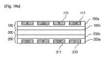
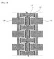
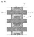
図10a〜図10cは、本発明の一実施形態に係るタッチパッドの形態を示した第2図である。 FIGS. 10A to 10C are second views illustrating a touch pad according to an exemplary embodiment of the present invention.
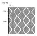
図10aを参照すると、本発明に係るタッチパッドは、第1センサパターン110と第1ダミーパターン111が交差配列する第1センサ部100、および第2センサパターン210と第2ダミーパターン211が交差配列する第2センサ部200を備えることができる。すなわち、第1センサパターン110の間と第2センサパターン210の間の空間にそれぞれダミーパターンを配置することができる。 Referring to FIG. 10A, the touch pad according to the present invention includes a
このとき、センサパターンとダミーパターン間の離隔距離は5μm〜30μm以内とし、特に15μm以上であることが好ましい。例えば、第1センサパターンと第1ダミーパターン間の離隔距離または第2センサパターンと第2ダミーパターン間の離隔距離は15μmに形成することができる。 At this time, the separation distance between the sensor pattern and the dummy pattern is set to 5 μm to 30 μm or less, and particularly preferably 15 μm or more. For example, the distance between the first sensor pattern and the first dummy pattern or the distance between the second sensor pattern and the second dummy pattern may be 15 μm.
図10bを参照すると、本発明に係るタッチパッドは、第1センサパターン110と第1ダミーパターン111が交差配列する第1センサ部100、および第2センサパターン210が配列される第2センサ部200を備えることができる。すなわち、第1センサパターン110間の空間にだけダミーパターンが配置され、第2センサパターン210間の空間にはダミーパターンが配置されない。 Referring to FIG. 10B, the touch pad according to the present invention includes a
図10cを参照すると、本発明に係るタッチパッドは、第1センサパターン110間の空間にはダミーパターンを配置せず、第2センサパターン210間の空間にだけダミーパターンを配置することもできる。 Referring to FIG. 10C, the touch pad according to the present invention may arrange the dummy pattern only in the space between the
このとき、本発明は、センサパターン間に配置されるダミーパターンを予め設定された形態を有する多数のサブダミーパターンに分割して形成するようになり、その分割する方式は、例えば、1)全体外郭の形状と同じ形状を有して均等面積を有するように分割する方式、2)全体外郭の形状とは異なる形状を有するが均等面積を有するように分割する方式、3)仮想の分割パターンによって分割し、仮想の分割パターン内のラインとダミーパターン内のメッシュの間に予め設定された角度を有するように分割する方式、4)ダミーパターン内のメッシュを規則的または不規則的に破断して分割する方式などを含むことができる。 At this time, according to the present invention, the dummy pattern arranged between the sensor patterns is formed by dividing into a number of sub-dummy patterns having a predetermined form. A method of dividing into a shape having the same shape as the outer contour and having an equal area, 2) a method of dividing into a shape having a shape different from the shape of the entire outer contour but having an equal area, 3) a virtual dividing pattern A method of dividing the mesh in the dummy pattern so as to have a preset angle between the lines in the virtual divided pattern and the mesh in the dummy pattern. 4) Breaking the mesh in the dummy pattern regularly or irregularly. It may include a division method.
このようなダミーパターンの分割によってセンサパターンとダミーパターンが部分短絡すると、センサパターンから当該ダミーパターンのうちの短絡したサブダミーパターンにだけ電流が流入し、ダミーパターン全体に電流が流入することを防いで機能の安全性を確保できることにより、センサパターンからダミーパターンに流入する誘電率を最小化してセンサ動作を向上させることができる。 If the sensor pattern and the dummy pattern are partially short-circuited due to such division of the dummy pattern, current flows from the sensor pattern only to the short-circuited sub-dummy pattern of the dummy pattern, and prevents current from flowing into the entire dummy pattern. As a result, the safety of the function can be ensured, so that the permittivity flowing from the sensor pattern to the dummy pattern can be minimized to improve the sensor operation.
図11a〜11bは、本発明の一実施形態に係るダミーパターンの形態を示した第1図である。 FIGS. 11A and 11B are first diagrams illustrating a form of a dummy pattern according to an embodiment of the present invention.
図11a〜図11bに示すように、本発明は、センサパターンの間に配置されるダミーパターンそれぞれを予め設定された形態を有する多数のサブダミーパターンに分割して形成し、ダミーパターンの連続性があるパターンの一部を切り、全体外郭の形状と同じ形状を有して均等面積を有するように分割することができる。 As shown in FIGS. 11A and 11B, the present invention divides each dummy pattern disposed between sensor patterns into a number of sub-dummy patterns having a predetermined form, and forms the dummy patterns. A part of a certain pattern can be cut and divided so as to have the same shape as the entire outer shape and to have an equal area.
図11aでは、ダミーパターン111の破断するラインとダミーパターン内のメッシュが平行に形成されることができる。 In FIG. 11A, a broken line of the
図11bでは、ダミーパターン111の破断するラインとダミーパターン内のメッシュが平行にならないように、予め設定された角度を有するように形成されることができる。 In FIG. 11B, the broken line of the
言い換えれば、本発明に係るダミーパターンは多数に分割されるが、ダミーパターン内のメッシュの方向とは関係なく、全体外郭の形成と同じ形状を有するように均等分割される。例えば、四角形状のダミーパターン111は、四角形状のサブダミーパターン111a、111b、111c、111d、111e、111f、111g、111h、111iに分割される。 In other words, the dummy pattern according to the present invention is divided into a large number, but is equally divided so as to have the same shape as that of the formation of the entire outline, regardless of the direction of the mesh in the dummy pattern. For example, the
上述した図11bに示すように、ダミーパターンが破断するラインとダミーパターン内のメッシュが予め設定された角度を有するように形成されることにより、相互モアレが発生するという問題を抑制することができる。 As shown in FIG. 11B described above, the problem that mutual moire occurs can be suppressed by forming the line in which the dummy pattern is broken and the mesh in the dummy pattern to have a predetermined angle. .
ダミーパターンは、パターンの一部が切れて多数のサブダミーパターンに分割されるため、分割された多数のサブダミーパターンそれぞれの端が開放して形成されるようになる。 Since the dummy pattern is divided into a large number of sub-dummy patterns by cutting off a part of the pattern, the ends of the divided large number of sub-dummy patterns are opened.
サブダミーパターンの境界でパターンの一部が切れていることは、サブダミーパターンの間に電気的に互いに絶縁するためであり、また切れていることによってサブダミーパターンのパターンの端が開放して形成されたことは、端が枠電極に連結しないことを意味する。 The fact that a part of the pattern is cut off at the boundary of the sub-dummy pattern is to electrically insulate each other between the sub-dummy patterns, and that the end of the pattern of the sub-dummy pattern is opened due to the cut. Forming means that the end is not connected to the frame electrode.
サブダミーパターンの端が開放することにより、枠電極に連結して連続性が消えて断絶したように見えるという問題点を解決し、実際に微細な間隔だけ離隔してはいるが、全体的に見たときには電極をユーザが連続したものと認識できるようにする。 By opening the end of the sub-dummy pattern, it solves the problem that it is connected to the frame electrode and the continuity disappears and it looks as if it is broken, and although it is actually separated by a fine interval, When viewed, the user can recognize the electrodes as continuous.
このとき、本実施形態のようにダミー連結部がない場合に、ダミーパターンの外郭形状を明確に知ることができるが、ダミー連結部がある場合にはそうではないため、ダミー連結部とダミーパターン間の区画を適切に分けてダミーパターンの外郭形状を定義しなければならない。 At this time, when there is no dummy connection portion as in the present embodiment, the outer shape of the dummy pattern can be clearly known, but when the dummy connection portion is present, this is not the case. The outer shape of the dummy pattern must be defined by appropriately dividing the sections between them.
図12a〜図12bは、本発明の一実施形態に係るダミーパターンの形態を示した第2図である。 FIGS. 12A and 12B are second diagrams illustrating a form of a dummy pattern according to an embodiment of the present invention.
図12a〜図12bに示すように、本発明は、センサパターンの間に配置されるダミーパターンそれぞれを予め設定された形態を有する多数のサブダミーパターンに分割して形成し、ダミーパターンの連続性があるパターンの一部を切り、全体外郭の形状とは異なる形状を有するが均等面積を有するように分割することができる。 As shown in FIGS. 12A and 12B, according to the present invention, each dummy pattern disposed between sensor patterns is divided into a plurality of sub-dummy patterns having a predetermined form and formed. A part of a certain pattern can be cut and divided so as to have a shape different from the shape of the entire outer periphery but to have an equal area.
図12aでは、分割されていない状態の六角形状を有するダミーパターン111を示している。 FIG. 12A shows a
図12bでは、六角形状のダミーパターン111を分割して全体外郭の形状と異なる形状を有するサブダミーパターンを形成し、各ダミーパターンの面積は等しくなる。 In FIG. 12B, the
例えば、図12aに示すように、六角形状を有するダミーパターン111の面積が90だとすると、図12bに示すように、六角形状とは異なる形状を有する9つのサブダミーパターン111a、111b、111c、111d、111e、111f、111g、111h、111iは、それぞれの面積が10になる。 For example, as shown in FIG. 12A, if the area of the
上述した図12bに示すように、ダミーパターンが破断するラインとダミーパターン内のメッシュの間に予め設定された角度を有するように形成されることにより、相互モアレが発生するという問題を抑制することができる。 As shown in FIG. 12b described above, since the dummy pattern is formed to have a preset angle between the broken line and the mesh in the dummy pattern, it is possible to suppress a problem that mutual moire occurs. Can be.
ダミーパターンは、パターンの一部が切れて多数のサブダミーパターンに分割するため、分割した多数のサブダミーパターンそれぞれの端が開放して形成されるようになる。 Since the dummy pattern is divided into a large number of sub-dummy patterns by cutting off a part of the pattern, each of the divided large number of sub-dummy patterns is formed with an open end.
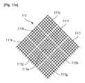
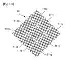
図13a〜図13bは、本発明の一実施形態に係るダミーパターンの形態を示した第3図である。 FIGS. 13A and 13B are third views showing the form of a dummy pattern according to an embodiment of the present invention.
図13a〜図13bに示すように、本発明は、センサパターンの間に配置されるダミーパターンそれぞれを予め設定された形態を有する多数のサブダミーパターンに分割して形成し、ダミーパターンの連続性があるパターンの一部を切り、全体外郭の形状とは異なる形状を有して異なる面積を有するように分割することができる。 As shown in FIGS. 13A and 13B, the present invention divides each dummy pattern disposed between sensor patterns into a number of sub-dummy patterns having a predetermined form and forms the dummy patterns. A part of a certain pattern can be cut and divided so as to have a shape different from the shape of the entire outer periphery and a different area.
図13aでは、仮想の分割パターン130内のラインとダミーパターン111内のメッシュの間に互いに平行に分割する。 In FIG. 13A, the lines in the virtual divided
図13bでは、仮想の分割パターン130内のラインとダミーパターン111内のメッシュの間に互いに平行しないように分割する。 In FIG. 13B, the lines in the virtual divided
このとき、本発明は、仮想の分割パターンを利用して分割し、仮想の分割パターン内のラインとダミーパターン内のメッシュの間に互いに平行するか平行しないように、予め設定された角度を有するように分割することができる。このように分割したサブダミーパターンのうち少なくとも1つのサブダミーパターンは、全体外郭の形状とは異なる形状を有して異なる面積を有するように分割される。 At this time, the present invention divides using the virtual division pattern, and has a preset angle between the lines in the virtual division pattern and the mesh in the dummy pattern so as to be parallel or non-parallel to each other. Can be divided as follows. At least one sub-dummy pattern among the sub-dummy patterns thus divided is divided so as to have a shape different from the shape of the entire outer periphery and to have a different area.
上述した図13bに示すように、ダミーパターンが破断するラインとダミーパターン内のメッシュの間に予め設定された角度を有するように形成されることにより、相互モアレが発生するという問題を抑制することができる。 As shown in FIG. 13b described above, since the dummy pattern is formed to have a predetermined angle between the broken line and the mesh in the dummy pattern, it is possible to suppress a problem that mutual moire occurs. Can be.
また、ダミーパターン内のメッシュを互いに平行しないように分割してサブダミーパターンを形成することにより、モアレを防ぐことができるだけでなく、視認性の向上にもさらに効果的となる。 Further, by dividing the mesh in the dummy pattern so as not to be parallel to each other to form the sub-dummy pattern, not only moire can be prevented but also the visibility can be improved more effectively.
ダミーパターンは、パターンの一部が切れて多数のサブダミーパターンに分割するため、分割した多数のサブダミーパターンそれぞれの端が開放して形成されるようになる。 Since the dummy pattern is divided into a large number of sub-dummy patterns by cutting off a part of the pattern, each of the divided large number of sub-dummy patterns is formed with an open end.
ここで、本発明は、仮想の分割パターンを利用してダミーパターンを分割する原理を説明しており、仮想の分割パターンは、図11a〜図12bにもすべて適用することができる。 Here, the present invention describes the principle of dividing a dummy pattern using a virtual division pattern, and the virtual division pattern can be applied to all of FIGS. 11A to 12B.
図14a〜図14bは、本発明の一実施形態に係るダミーパターンの形態を示した第4図である。 FIGS. 14A and 14B are fourth diagrams illustrating a form of a dummy pattern according to an embodiment of the present invention.
図14a〜図14bに示すように、本発明は、センサパターンの間に配置されるダミーパターンそれぞれを多数の予め設定された形態に分割して形成し、ダミーパターンの連続性があるパターンの一部を切り、ダミーパターン内のメッシュを予め設定された範囲内で規則的または不規則的に破断して分割することができる。 As shown in FIG. 14A to FIG. 14B, the present invention divides each of dummy patterns arranged between sensor patterns into a number of preset forms and forms one of the patterns. The portion can be cut off, and the mesh in the dummy pattern can be broken regularly or irregularly within a preset range to be divided.
このように規則的または不規則的に形成されたサブダミーパターンの長さは、0.3mm〜1.5mmであることが好ましい。 It is preferable that the length of the sub dummy pattern formed regularly or irregularly is 0.3 mm to 1.5 mm.
図14aでは、ダミーパターン111内のメッシュを予め設定された範囲内で規則的に破断して分割することができ、破断した線の長さが等しくなるように形成することができる。 In FIG. 14A, the mesh in the
例えば、横方向に破断された線の長さLxと縦方向に破断された線の長さLyは等しい。 For example, the length Lx of the line broken in the horizontal direction is equal to the length Ly of the line broken in the vertical direction.
図14bでは、ダミーパターン111内のメッシュを予め設定された範囲内で不規則的に破断して分割することができ、破断された線の長さが互いに異なるように形成することができる。 In FIG. 14b, the mesh in the
破断された線の長さが予め設定された範囲内で互いに異なるように形成できることは勿論である。 Of course, the lengths of the broken lines can be different from each other within a predetermined range.
例えば、横方向と判断された線の長さLx1とLx2またはLy1とLy2は、ランダムに決められて互いに異なる。 For example, the lengths Lx1 and Lx2 or Ly1 and Ly2 of the lines determined to be in the horizontal direction are randomly determined and different from each other.
ダミーパターンは、パターンの一部が切れて多数のサブダミーパターンに分割するため、分割した多数のサブダミーパターンそれぞれの端が開放して形成されるようになる。 Since the dummy pattern is divided into a large number of sub-dummy patterns by cutting off a part of the pattern, each of the divided large number of sub-dummy patterns is formed with an open end.
上述した図11a〜図14bのように、ダミーパターンを多数のサブダミーパターンに分割し、分割した各サブダミーパターンは単位メッシュ5つ以上で形成することが好ましく、その理由は視認性の向上にさらに効果的であるためである。 As shown in FIGS. 11A to 14B described above, it is preferable that the dummy pattern is divided into a large number of sub-dummy patterns, and each of the divided sub-dummy patterns is formed of five or more unit meshes, because the reason is to improve visibility. This is because it is more effective.
このとき、本発明は、センサパターンの間にダミーパターンを配置し、センサパターンとダミーパターンの間に位置し、センサパターンとダミーパターン間の境界面に沿って予め設定された距離だけ離隔したダミーパターンと物理的に分離した補助ダミーパターンを追加で形成することができる。また、補助ダミーパターンは、必要によっては分割して形成することができる。 At this time, according to the present invention, a dummy pattern is arranged between the sensor patterns, the dummy pattern is located between the sensor pattern and the dummy pattern, and is separated by a predetermined distance along a boundary surface between the sensor pattern and the dummy pattern. An auxiliary dummy pattern physically separated from the pattern can be additionally formed. Further, the auxiliary dummy pattern can be divided and formed if necessary.
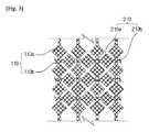
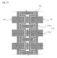
図15は、本発明の一実施形態に係るダミーパターンの形態を示した第5図である。 FIG. 15 is a fifth diagram showing the form of the dummy pattern according to one embodiment of the present invention.
図15に示すように、本発明は、ダミーパターンの間にダミー連結部が形成されている場合、センサパターン110の間にダミーパターン111を配置し、センサパターン110とダミーパターン111の間に補助ダミーパターン112を追加で形成することができる。また、必要によっては、センサパターンとダミーパターンの間に多数の補助ダミーパターンを形成することができる。 As shown in FIG. 15, according to the present invention, when a dummy connection portion is formed between dummy patterns, a
ここで、本発明の実施形態では、ダミーパターンとダミー連結部を区分せずにダミーパターンとしてのみ説明しているが、ダミー連結部を含むダミーパターンを意味している。 Here, in the embodiment of the present invention, the dummy pattern and the dummy connection portion are described as the dummy pattern without being divided, but the dummy pattern includes the dummy connection portion.
このとき、補助ダミーパターン112は、センサパターン110とダミーパターン111の間の境界面に沿って形成され、センサパターン110とダミーパターン111それぞれから予め設定された距離だけ離隔して形成することができる。言い換えれば、補助ダミーパターン112は、一側のセンサパターン110と予め設定された距離だけ離隔しており、他側のダミーパターン111とも予め設定された距離だけ離隔して形成することができる。 At this time, the
また、補助ダミーパターン112は、センサパターン110との離隔距離とダミーパターン111との離隔距離が互いに等しくなるように形成されたり、互いに異なるように形成されることができる。 In addition, the
このように形成された補助ダミーパターン112は、当該センサパターン110の外郭線に沿って予め設定された距離だけ離隔して形成されるため、当該センサパターン110の外郭線と同じ形状を有するようになる。 The
補助ダミーパターン112は、センサパターン110とダミーパターン111の間の境界面に沿って帯形態に形成することができる。このような補助ダミーパターン112は、センサパターン110とダミーパターン111の間の境界面に沿って形成されるため、同じ方向の同じライン、例えば、X軸方向の同じx座標またはY軸方向の同じy座標上には1つの補助ダミーパターン112が形成されることができる。 The
勿論、同じ方向の同じライン上に位置する補助ダミーパターン112は連続性があるパターンで形成することができるが、必ずしもこれに限定されるものではなく、必要によっては分割することができる。すなわち、連続性があるパターンの一部を切って多数の補助ダミーパターン112に分割することができる。 Of course, the
また、ダミーパターン111は、多数の予め設定された形態に分割して形成されたり、配置するダミーパターンを構成するメッシュを規則的または不規則的に断線させて形成することができる。 Further, the
このようなダミーパターン111と補助ダミーパターン112それぞれの端が開放して形成されるようになる。 The end of each of the
このように、ダミーパターン111と補助ダミーパターン112それぞれの境界でパターンの一部が切れていることは、ダミーパターン111と補助ダミーパターン112の間に電気的に互いに絶縁するためであり、また切れていることによってダミーパターン111と補助ダミーパターン112それぞれのパターンの端が開放して形成されることは、端が枠電極に連結しないことを意味する。 The fact that a part of the pattern is cut off at the boundary between each of the
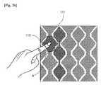
図16は、本発明の一実施形態に係る補助ダミーパターンの配置形態を示した図である。 FIG. 16 is a diagram showing an arrangement of auxiliary dummy patterns according to an embodiment of the present invention.
図16に示すように、補助ダミーパターンは、センサパターン110とダミーパターン111の間の境界面に沿って形成され、一側のセンサパターン110と予め設定された距離d1だけ離隔して形成することができる。ここで、センサパターン110との離隔距離d1は、30μm以下とすることができる。 As shown in FIG. 16, the auxiliary dummy pattern is formed along the boundary between the
この反面、補助ダミーパターン112は、他側のダミーパターン111とも予め設定された距離d2だけ離隔して形成することができ、ここで、ダミーパターン111との離隔距離d2は、20μm以下とすることができる。 On the other hand, the
このように補助ダミーパターン112は、センサパターン110との離隔距離とダミーパターン111との離隔距離が互いに等しい離隔距離を有するように形成されたり、互いに異なる離隔距離を有するように形成されることができる。 As described above, the
また、補助ダミーパターン112は、センサパターン110とダミーパターン111の間に帯形態で形成され、厚さwは一定の大きさとすることができる。ここで、厚さwは100μm以下とすることができる。 In addition, the
図17は、本発明の一実施形態に係るダミーパターンの形態を示した第6図である。 FIG. 17 is a sixth diagram illustrating a form of a dummy pattern according to an embodiment of the present invention.
図17に示すように、本発明は、ダミーパターンの間のダミー連結部が形成されている場合、センサパターン110の間にダミーパターン111を配置し、センサパターン110とダミーパターン111の間に補助ダミーパターン112を追加で形成することができる。 As shown in FIG. 17, according to the present invention, when a dummy connection portion is formed between dummy patterns, a
本発明では、ダミーパターン111aとダミー連結部111bが物理的に分離し、予め設定された距離だけ離隔するように形成することができる。 In the present invention, the
このとき、補助ダミーパターン112は、センサパターン110とダミーパターン111の間の境界面に沿って形成され、センサパターン110とダミーパターン111それぞれから予め設定された距離だけ離隔して形成することができる。言い換えれば、補助ダミーパターン112は、一側のセンサパターン110と予め設定された距離だけ離れており、他側のダミーパターン111とも予め設定された距離だけ離れて形成することができる。 At this time, the
また、補助ダミーパターン112は、センサパターン110との離隔距離とダミーパターン111との離隔距離が互いに等しくなるように形成されたり、互いに異なるように形成されることができる。 In addition, the
このように形成された補助ダミーパターン112は、当該センサパターン110の外郭線に沿って予め設定された距離だけ離隔して形成されるため、当該センサパターン110の外郭線と同じ形状を有するようになる。 The
補助ダミーパターン112は、センサパターン110とダミーパターン111の間の境界面に沿って帯形態に形成することができる。このような補助ダミーパターン112は、センサパターン110とダミーパターン111の間の境界面に沿って形成されるため、同じ方向の同じライン、例えば、X軸方向の同じx座標またはY軸方向の同じy座標上には1つの補助ダミーパターンが形成されることができる。 The
勿論、同じ方向の同じライン上に位置する補助ダミーパターン112は、連続性があるパターンで形成することができるが、必ずしもこれに限定されるものではなく、必要によっては分割することができる。すなわち、連続性があるパターンの一部を切って多数の補助ダミーパターン112に分割することができる。 Of course, the
また、ダミーパターン111は、多数の予め設定された形態に分割されて形成されたり、配置されるダミーパターンを構成するメッシュを規則的または不規則的に断線させて形成されることができる。 In addition, the
このようなダミーパターン111aと補助ダミーパターン112それぞれの端が開放して形成されるようになる。ダミーパターン111aと分離したダミー連結部111bの端も開放して形成されるようになることは勿論である。 The ends of the
このように、ダミーパターン111と補助ダミーパターン112それぞれの境界でパターンの一部が切れていることは、ダミーパターン111と補助ダミーパターン112の間に電気的に互いに絶縁するためであり、また切れたことによってダミーパターン111と補助ダミーパターン112それぞれのパターンの端が開放して形成されることは、端が枠電極に連結しないことを意味する。 The fact that a part of the pattern is cut off at the boundary between each of the
図18a〜図18bは、本発明の一実施形態に係るダミーパターンの形態を示した第7図である。 FIGS. 18A and 18B are diagrams illustrating a dummy pattern according to an embodiment of the present invention.
図18aに示すように、本発明は、ダミーパターン間のダミー連結部が形成されていない場合、センサパターン110の間にダミーパターン111を配置し、センサパターン110とダミーパターン111の間に補助ダミーパターン112を追加で形成することができる。 As shown in FIG. 18A, in the present invention, when a dummy connection between dummy patterns is not formed, a
このようにダミー連結部が形成されていない場合には、センサパターン110間の間隔が、図15および図17で説明したセンサパターンの間隔よりも狭く形成されることができる。 When the dummy connection portion is not formed as described above, the interval between the
このとき、補助ダミーパターン112は、センサパターン110とダミーパターン111間の境界面に沿って形成され、センサパターン110とダミーパターン111それぞれから予め設定された距離だけ離隔して形成されることができる。言い換えれば、補助ダミーパターン112は、一側のセンサパターン110と予め設定された距離だけ離れており、他側のダミーパターン111とも予め設定された距離だけ離れて形成されることができる。 At this time, the
また、補助ダミーパターン112は、センサパターン110との離隔距離とダミーパターン111との離隔距離が互いに等しくなるように形成されたり、互いに異なるように形成されることができる。 In addition, the
このように形成された補助ダミーパターン112は、当該センサパターン110の外郭線に沿って予め設定された距離だけ離隔して形成されるため、当該センサパターン110の外郭線と同じ形状を有するようになる。 The
補助ダミーパターン112は、センサパターン110とダミーパターン111の間の境界面に沿って帯形態に形成されることができる。このような補助ダミーパターン112は、センサパターン110とダミーパターン111間の境界面に沿って形成されるため、同じ方向の同じライン、例えば、X軸方向の同じx座標またはY軸方向の同じy座標上には1つの補助ダミーパターン112が形成されることができる。 The
勿論、同じ方向の同じライン上に位置する補助ダミーパターン112は連続性があるパターンで形成されることができるが、必ずしもこれに限定されるものではなく、必要によっては分割することができる。すなわち、連続性があるパターンの一部を切って多数の補助ダミーパターン112に分割することができる。 Of course, the
また、ダミーパターン111は、多数の予め設定された形態に分割して形成されたり、配置するダミーパターンを構成するメッシュを規則的または不規則的に断線させて形成されることができる。 Further, the
このようなダミーパターン111と補助ダミーパターン112それぞれの端が開放して形成されるようになる。 The end of each of the
このように、ダミーパターン111と補助ダミーパターン112それぞれの境界でパターンの一部が切れていることは、ダミーパターン111と補助ダミーパターン112の間に電気的に互いに絶縁するためであり、また切れたことによってダミーパターン111と補助ダミーパターン112それぞれのパターンの端が開放して形成されることは、端が枠電極に連結しないことを意味する。 The fact that a part of the pattern is cut off at the boundary between each of the
図18bに示すように、本発明は、ダミーパターンの間のダミー連結部が形成されていない場合、センサパターン110の間にダミーパターン111を配置し、センサパターン110とダミーパターン111の間に補助ダミーパターン112を追加で形成することができる。 As shown in FIG. 18B, the present invention arranges a
このようにダミー連結部が形成されていない場合には、センサパターン110の間隔が、図15および図17で説明したセンサパターンの間隔よりも狭く形成されることができる。 When the dummy connection portion is not formed as described above, the interval between the
このとき、補助ダミーパターン112は、センサパターン110とダミーパターン111間の境界面に沿って形成され、センサパターン110とダミーパターン111それぞれから予め設定された距離だけ離隔して形成されることができる。言い換えれば、補助ダミーパターン112は、一側のセンサパターン110と予め設定された距離だけ離れており、他側のダミーパターン111とも予め設定された距離だけ離れて形成されることができる。 At this time, the
また、補助ダミーパターン112は、センサパターン110との離隔距離とダミーパターン111との離隔距離が互いに等しくなるように形成されたり、互いに異なるように形成されることができる。 In addition, the
このように形成された補助ダミーパターン112は、当該ダミーパターン110の外郭線に沿って予め設定された距離だけ離隔して形成されるため、当該ダミーパターン110の外郭線と同じ形状を有するようになる。 The
補助ダミーパターン112は、ダミーパターン111の外郭線に沿って帯形態に形成されることができる。このような補助ダミーパターン112は、ダミーパターン111の外郭線に沿って形成されるため、ダミーパターン111ごとに外郭を囲むように1つの補助ダミーパターン112が形成されることができる。すなわち、1つの補助ダミーパターン112ごとに物理的に分離して形成される。 The
勿論、ダミーパターンを囲む補助ダミーパターン112は連続性があるパターンで形成することができるが、必ずしもこれに限定されるものではなく、必要によっては分割することができる。すなわち、連続性があるパターンの一部を切って多数の補助ダミーパターン112に分割することができる。 Of course, the
また、ダミーパターン111は、多数の予め設定された形態に分割されて形成されたり、配置するダミーパターンを構成するメッシュを規則的または不規則的に断線させて形成されることができる。 Further, the
このようなダミーパターン111と補助ダミーパターン112それぞれの端が開放して形成されるようになる。 The end of each of the
このように、ダミーパターン111と補助ダミーパターン112それぞれの境界でパターンの一部が切れていることは、ダミーパターン111と補助ダミーパターン112の間に電気的に互いに絶縁するためであり、また切れたことによってダミーパターン111と補助ダミーパターン112それぞれのパターンの端が開放して形成されることは、端が枠電極に連結しないことを意味する。 The fact that a part of the pattern is cut off at the boundary between each of the
このように、本発明は、X座標を感知するための第1センサパターンを含む第1センサ部とY座標を感知するための第2センサパターンを含む第2センサ部とで構成され、第1センサ部と第2センサ部が互いに接合して形成されたタッチスクリーンセンサに多様な形態のダミーパターンを適用した例を示しているが、必ずしもこれに限定されるものではなく、X座標を感知するための第1センサパターンとY座標を感知するための第2センサパターンを単一基板の表面に共に配列するように構成されたタッチスクリーンセンサにも適用することができる。 As described above, the present invention includes the first sensor unit including the first sensor pattern for sensing the X coordinate and the second sensor unit including the second sensor pattern for sensing the Y coordinate. Although an example in which various types of dummy patterns are applied to a touch screen sensor formed by joining a sensor unit and a second sensor unit to each other is shown, the present invention is not limited to this, and an X coordinate is sensed. A first sensor pattern for sensing the Y coordinate and a second sensor pattern for sensing the Y coordinate may be applied to a touch screen sensor configured to be arranged together on the surface of a single substrate.
勿論、ここでは、単一基板の表面に第1センサパターンと第2センサパターンがすべて形成される場合を一例として説明しているが、必ずしもこれに限定されるものではなく、同一基板上に第1センサパターンと第2センサパターンが多様な形態で形成されてもよいことは自明である。 Of course, here, the case where the first sensor pattern and the second sensor pattern are all formed on the surface of the single substrate has been described as an example, but the present invention is not necessarily limited to this, and It is obvious that the first sensor pattern and the second sensor pattern may be formed in various forms.
例えば、第1方向に形成された第1センサパターンと第2方向に形成された第2センサパターンが単一基板の表面の両側面にそれぞれ配列するように構成されたタッチスクリーンセンサにも、本発明の一実施形態に係る多様な形態のダミーパターンを適用することができる。 For example, the present invention is applicable to a touch screen sensor in which a first sensor pattern formed in a first direction and a second sensor pattern formed in a second direction are arranged on both side surfaces of a single substrate, respectively. Various types of dummy patterns according to an embodiment of the present invention can be applied.
図19は、本発明の他の実施形態に係るタッチスクリーンセンサの構成を示した図である。 FIG. 19 is a diagram illustrating a configuration of a touch screen sensor according to another embodiment of the present invention.
図19に示すように、本発明に係るタッチスクリーンセンサは、1つのセンサ部100を備えることができ、ここで、センサ部100は、X座標を感知するための第1センサパターン110とY座標を感知するための第2センサパターン210が1つの基板に配列するように構成することができる。 As shown in FIG. 19, the touch screen sensor according to the present invention may include one
このとき、第1センサパターンをセンシング信号を感知するセンシング電極とし、第2センサパターンを第1センサパターンと電気的に分離して駆動信号を感知する駆動電極とすると仮定することができる。 At this time, it can be assumed that the first sensor pattern is a sensing electrode for sensing a sensing signal, and the second sensor pattern is a drive electrode for sensing a drive signal by being electrically separated from the first sensor pattern.
このような複数のセンシング電極それぞれは、第1方向に沿って延長して形成される感知バー形態で配置され、複数の駆動電極それぞれは、第1方向と交差する第2方向上に配置することができる。ここで、第1方向は横方向またはX軸方向を示し、第2方向は縦方向またはY軸方向を示す。 Each of the plurality of sensing electrodes may be arranged in the form of a sensing bar extending along the first direction, and each of the plurality of driving electrodes may be arranged in a second direction intersecting the first direction. Can be. Here, the first direction indicates the horizontal direction or the X-axis direction, and the second direction indicates the vertical direction or the Y-axis direction.
例えば、横方向に長く形成されたY座標を感知するための第2センサパターン210を縦方向に一定間隔ごとに離隔して配置し、第2センサパターン210に並んで隣接してX座標を感知するための多数の第1センサパターン110を横方向に一定間隔ごとに離隔して配置することができる。 For example, a
すなわち、1つの第2センサパターン210ごとに多数の第1センサパターン110を並べて配置する。 That is, a large number of
このように配置される1つのセンシング電極と多数の駆動電極を含む感知領域が形成されることができる。本発明に係る感知領域は、1つのセンシング電極と多数の駆動電極間の包含関係に限定されるものではなく、多様な形態で実現することができる。 Thus, a sensing region including one sensing electrode and a plurality of driving electrodes may be formed. The sensing area according to the present invention is not limited to the inclusion relationship between one sensing electrode and a number of driving electrodes, but may be implemented in various forms.
このように配置された第1センサパターン110と第2センサパターン210それぞれに配線電極400が連結することができる。ここで、配線電極400は、第1センサパターン110と第2センサパターン210から感知されたタッチ信号を外部駆動回路(図示せず)に伝達する役割をする。 The
また、第1センサパターン110または第2センサパターン210と配線電極の間にダミーパターン111を形成することができる。また、第1センサパターン110それぞれに配線電極が連結することによって配線電極の間に空間が生じ、その空間にダミーパターンを形成することができる。また、空間の大きさにより、ダミーパターンの大きさが異なることができる。このようなダミーパターン111は、第1センサパターン110または第2センサパターン210と類似する形状のパターンまたは同じ形状のパターンで形成することができる。 In addition, a
このように多数のセンシング電極と多数の感知電極は、基板の同じ面に配置されて断層構造を形成することができる。 As described above, the plurality of sensing electrodes and the plurality of sensing electrodes may be arranged on the same surface of the substrate to form a tomographic structure.
このとき、1枚の基板に第1センサパターンと第2センサパターンを形成するときにメタルメッシュで構成するようになり、この理由は、ITOは折り曲げることができないためフレキシブル基板に使用することが不可能であり、中大型面積での使用が不可能である反面、メタルメッシュはフレキシブルと中大型面積に使用可能なだけでなく、ITOに比べて応答速度が速いためである。 At this time, when the first sensor pattern and the second sensor pattern are formed on one substrate, the first sensor pattern and the second sensor pattern are formed of a metal mesh. This is because ITO cannot be bent and cannot be used for a flexible substrate. Although it is possible and cannot be used in a medium or large area, the metal mesh is not only flexible and usable in a medium or large area, but also has a higher response speed compared to ITO.
また、1枚の基板に第1センサパターンと第2センサパターンを形成するときにダミーパターンを形成するようになり、この理由は、メタルメッシュで構成するときにモアレが生じる現象が発生するため、空間にダミーパターンを形成してモアレを防ぐためである。 Further, when the first sensor pattern and the second sensor pattern are formed on one substrate, a dummy pattern is formed. This is because moiré occurs when a metal mesh is used. This is because a moiré is prevented by forming a dummy pattern in the space.
なお、基板上にパターン密集度差によってパターンが視認される現象が発生するため、空間にダミーパターンを形成することにより、均一なパターンによってパターンが視認される現象を抑制するためである。 This is because a phenomenon in which the pattern is visually recognized due to the pattern density difference on the substrate occurs. Therefore, by forming a dummy pattern in the space, the phenomenon in which the pattern is visually recognized by a uniform pattern is suppressed.
図20は、図19に示すセンサパターン、ダミーパターン、配線電極の形状を拡大して示した図である。 FIG. 20 is an enlarged view of the shapes of the sensor pattern, dummy pattern, and wiring electrode shown in FIG.
図20に示すように、図19の領域Aを拡大して詳察すると、センサパターン110、210、ダミーパターン111、配線電極400は1つのセンサ部に形成され、一定方向のパターンで形成されることができる。一定方向のパターンとは、連続性あるパターンで一定方向に形成された線が相互交差するメッシュ形状のパターンであることが好ましい。 As shown in FIG. 20, when the area A in FIG. 19 is enlarged and examined in detail, the
センサパターン110、210、ダミーパターン111、配線電極400それぞれの端は開放して形成されることができる。センサパターン110、210、ダミーパターン111、配線電極400それぞれの境界でパターンの一部が切れていることは電気的に互いに絶縁するためであり、また切れたことによってパターンの端が開放して形成されることは、端が枠電極に連結しないことを意味する。 Each end of the
このようなセンサパターン110、210、ダミーパターン111、配線電極400は、陽刻形状または陰刻形状を利用して形成することができ、センサパターン110、210と配線電極400は電気的に活性の電極で形成され、ダミーパターン111は電気的に不活性の電極で形成される。 The
図21は、図19に示すダミーパターンの配置位置と形態を拡大して示した図である。 FIG. 21 is an enlarged view showing the arrangement position and form of the dummy pattern shown in FIG.
図21に示すように、図19の領域Bを拡大して詳察すると、センサパターン110、210と配線電極400の間にダミーパターン111を形成し、このようなダミーパターン111は、センサパターン110、210と配線電極400の間の間隔によってその大きさが異なることができる。 As shown in FIG. 21, when the region B in FIG. 19 is enlarged and examined in detail, a
例えば、ダミーパターン111a2は、ダミーパターン111a1よりもその幅をさらに広く形成することができ、センサパターン110、210と配線電極400の間の間隔が広くなるほどダミーパターン111の幅も広くなる。このとき、ダミーパターンは分割され、2つ以上のサブダミーパターンで形成されることができる。ダミーパターンそれぞれは、互いに異なる数のサブダミーパターンに分割して形成されることができる。特に、ダミーパターンの大きさによってサブダミーパターンの数が異なることができる。 For example, the width of the dummy pattern 111a2 can be formed wider than that of the dummy pattern 111a1, and the width of the
ここでは、本発明に係るダミーパターン111がセンサパターン110、210と配線電極400の間に形成される場合を一例として説明しているが、必ずしもこれに限定されるものではなく、センサパターンとセンサパターンの間または配線電極と配線電極の間など多様な位置に形成することができる。このように形成されたダミーパターン111は、予め設定された形態を有する多数のサブダミーパターンに分割して形成され、その方式は多様である。 Here, the case where the
一例として、1)図11a〜図11bのように、ダミーパターンの連続性があるパターンの一部を切り、全体外郭の形状と同じ形状を有して均等面積を有するように分割することができる。 As an example, 1) As shown in FIGS. 11A and 11B, a part of a pattern having a continuity of a dummy pattern can be cut and divided so as to have the same shape as the entire outer shape and have an equal area. .
このとき、図11aのように、ダミーパターンの破断するラインとダミーパターン内のメッシュが平行に形成されたり、図11bのように、ダミーパターンと破断するラインとダミーパターン内のメッシュが平行ではなく、予め設定された角度を有するように形成されることができる。 At this time, as shown in FIG. 11a, the broken line of the dummy pattern and the mesh in the dummy pattern are formed in parallel, or as shown in FIG. 11b, the broken line of the dummy pattern and the mesh in the dummy pattern are not parallel. , May have a predetermined angle.
他の例として、2)図12a〜図12bのように、ダミーパターンの連続性があるパターンの一部を切り、全体外郭の形状と異なる形成を有するが均等面積を有するように分割することができる。 As another example, 2) As shown in FIGS. 12A and 12B, a part of a pattern having a continuity of a dummy pattern may be cut and divided so as to have a shape different from that of the entire outer periphery but to have an equal area. it can.
他の例として、3)図13a〜図13bのように、ダミーパターンの連続性があるパターンの一部を切り、全体外郭の形状と異なる形状を有して異なる面積を有するように分割することができる。 As another example, 3) As shown in FIGS. 13A to 13B, a part of a pattern having a continuity of a dummy pattern is cut and divided so as to have a shape different from the shape of the entire outer periphery and a different area. Can be.
このとき、図13aのように、仮想の分割パターン内のラインとダミーパターン内のメッシュの間に互いに平行に分割したり、図13bのように、仮想の分割パターン内のラインとダミーパターン内のメッシュの間に互いに平行しないように分割することができる。 At this time, as shown in FIG. 13A, the lines in the virtual divided pattern and the meshes in the dummy pattern are divided in parallel with each other, or as shown in FIG. The meshes can be divided so that they are not parallel to each other.
他の例として、図14a〜図14bのように、ダミーパターンの連続性があるパターンの一部を切り、ダミーパターン内のメッシュを予め設定された範囲内で規則的または不規則的に破断して分割することができる。 As another example, as shown in FIG. 14A to FIG. 14B, a part of a pattern having continuity of a dummy pattern is cut, and meshes in the dummy pattern are broken regularly or irregularly within a preset range. Can be divided.
このとき、図14aのように、ダミーパターン内のメッシュを予め設定された範囲内で規則的に破断し、その破断した線の長さが等しくなるように形成したり、図14bのように、ダミーパターン内のメッシュを予め設定された範囲内で不規則的に破断し、その破断した線の長さが互いに異なるように形成することができる。 At this time, as shown in FIG. 14a, the mesh in the dummy pattern is regularly broken within a preset range, and the broken lines are formed to have the same length, or as shown in FIG. 14b, The mesh in the dummy pattern can be broken irregularly within a preset range so that the broken lines have different lengths.
他の例として、図15のように、ダミーパターンの間にダミー連結部が形成されている場合、センサパターンの間にダミーパターンを配置し、センサパターンとダミーパターンの間に補助ダミーパターンを追加で形成することができる。 As another example, when a dummy connection portion is formed between dummy patterns as shown in FIG. 15, a dummy pattern is arranged between sensor patterns and an auxiliary dummy pattern is added between the sensor patterns and the dummy patterns. Can be formed.
他の例として、図17のように、ダミーパターンの間のダミー連結部が形成されている場合、センサパターンとダミーパターンの間に補助ダミーパターンを追加で形成し、ダミーパターンとダミー連結部が物理的に分離し、予め設定された距離だけ離隔するように形成することができる。 As another example, as shown in FIG. 17, when a dummy connection portion between dummy patterns is formed, an auxiliary dummy pattern is additionally formed between the sensor pattern and the dummy pattern, and the dummy pattern and the dummy connection portion are formed. They can be formed so as to be physically separated and separated by a predetermined distance.
他の例として、図18a〜図18bのように、ダミーパターンの間のダミー連結部が形成されていない場合、センサパターンとダミーパターンの間に補助ダミーパターンを追加で形成し、図18aのように、センサパターンの間隔が図15および図17で説明したセンサパターンの間隔よりも狭く形成したり、図18bのように、ダミーパターンの外郭を囲むように形成することができる。 As another example, as shown in FIG. 18A to FIG. 18B, when the dummy connection portion between the dummy patterns is not formed, an auxiliary dummy pattern is additionally formed between the sensor pattern and the dummy pattern. Meanwhile, the interval between the sensor patterns can be formed to be narrower than the interval between the sensor patterns described with reference to FIGS. 15 and 17, or can be formed so as to surround the outline of the dummy pattern as shown in FIG. 18B.
このとき、ダミーパターンと補助ダミーパターンそれぞれは、多数に分割して形成されることができる。 At this time, each of the dummy pattern and the auxiliary dummy pattern can be formed by dividing into a large number.
また、補助ダミーパターンは、ダミーパターンの形態や位置により、センサパターンとダミーパターンの間だけではなく、センサパターンとセンサパターンの間または配線電極と配線電極の間にも形成されることができる。 Further, depending on the form and position of the dummy pattern, the auxiliary dummy pattern can be formed not only between the sensor patterns and the dummy patterns but also between the sensor patterns and between the sensor patterns or between the wiring electrodes.
上述した実施形態はその一例であって、本発明が属する技術分野において通常の知識を有する者であれば、本発明の本質的な特性から逸脱しない範囲で多様な修正および変形が可能だろう。したがって、本発明に開示された実施形態は、本発明の技術思想を限定するためのものではなく説明するためのものであり、このような実施形態によって本発明の技術思想の範囲が限定されるものではない。本発明の保護範囲は添付の特許請求の範囲によって解釈されなければならず、それと同等な範囲内にあるすべての技術思想は、本発明の権利範囲に含まれると解釈されなければならない。 The above-described embodiment is merely an example, and those skilled in the art to which the present invention pertains will be able to make various modifications and variations without departing from the essential characteristics of the present invention. Therefore, the embodiments disclosed in the present invention are not intended to limit the technical idea of the present invention, but to explain, and the scope of the technical idea of the present invention is limited by such embodiments. Not something. The protection scope of the present invention should be construed according to the appended claims, and all technical ideas falling within the scope of the claims should be construed as being included in the scope of the present invention.
Claims (9)
Translated fromJapanese前記第1センサ部と重なっており、前記第1方向と交差する第2方向に形成された第2センサパターンと前記第2センサパターンの間に第2ダミーパターンが配列される第2センサ部、
を備え、前記第1ダミーパターンと前記第2ダミーパターンは、物理的に分離する少なくとも2つ以上の小さなダミーパターンからなり、
分離する前記少なくとも2つ以上の小さなダミーパターンの境界線は、当該ダミーパターンを構成するメッシュの方向と互いに並行しないように形成されており、
前記第1ダミーパターンは、その内部メッシュを規則的に破断させるための前記境界線によって物理的に分離された2つ以上の小さなダミーパターンからなり、前記第2ダミーパターンは、その内部のメッシュを規則的に破断させるための前記境界線によって物理的に分離される少なくとも2つ以上の小さなダミーパターンからなり、
前記第1ダミーパターン内の小さなダミーパターンの前記境界線と前記第1ダミーパターンのメッシュの方向との間には少なくとも1つの所定の第1角度が形成され、前記第1ダミーパターン内の小さなダミーパターンの前記境界線は多数の前記第1ダミーパターンの前記内部メッシュを分離し、
前記第2ダミーパターン内の小さなダミーパターンの前記境界線と前記第2ダミーパターンのメッシュの方向との間には少なくとも1つの所定の第2角度が形成され、前記第2ダミーパターン内の小さなダミーパターンの前記境界線は多数の前記第2ダミーパターンの前記内部メッシュを分離することを特徴とする、静電容量式タッチスクリーンのためのダミーパターンを使用するタッチパッドの構造。A first sensor portion in which a first dummy pattern is arranged between a first sensor pattern formed in a first direction and the first sensor pattern; and a first sensor portion overlapping with the first sensor portion and intersecting the first direction. A second sensor portion in which a second dummy pattern is arranged between a second sensor pattern formed in a second direction and the second sensor pattern.
Wherein the first dummy pattern and the second dummy pattern comprise at least two or more small dummy patterns that are physically separated,
The boundary lines of the at least two or more small dummy patterns to be separated are formed so as not to be parallel to the direction of the mesh forming the dummy pattern,
The first dummy pattern iscomposed of two or more small dummy patterns physically separated by theboundary linefor regularly breaking the internal mesh, and the second dummy pattern includes an internal mesh.Consisting of at least two or more small dummy patterns physically separated bysaid boundary linefor regular breaking ,
At least one predetermined first angle is formed between theboundary of the small dummy pattern inthe first dummy pattern and the direction of the mesh ofthe first dummy pattern, and the small dummy in the first dummy pattern is formed.The boundary of the pattern separates the inner mesh of a number ofthe first dummy patterns;
At least one predetermined second angle is formed between theboundary of the small dummy pattern inthe second dummy pattern and the direction of the mesh ofthe second dummy pattern, and the small dummy in the second dummy pattern is formed. The structure of a touch pad using a dummy pattern for a capacitive touch screen, wherein the boundary of the patternseparates the internal meshes of a plurality ofthe second dummy patterns.
前記第2ダミーパターンは、前記第1センサパターンの位置に対応する領域に配置されることを特徴とする、請求項1に記載の静電容量式タッチスクリーンのためのダミーパターンを使用するタッチパッドの構造。The first dummy pattern is arranged in a region corresponding to a position of the second sensor pattern,
The touch pad of claim 1, wherein the second dummy pattern is disposed in an area corresponding to a position of the first sensor pattern. 4. Structure.
前記2つ以上の小さなダミーパターンそれぞれは、第1ダミーパターンまたは第2ダミーパターンの全体外郭の形状と同じ形状を有して均等面積を有するように形成されることを特徴とする、請求項1に記載の静電容量式タッチスクリーンのためのダミーパターンを使用するタッチパッドの構造。The first dummy pattern and the second dummy pattern each include two or more small dummy patterns having a predetermined form,
The method of claim 1, wherein each of the two or more small dummy patterns has the same shape as the entire outer shape of the first dummy pattern or the second dummy pattern and has a uniform area. Structure of a touch pad using a dummy pattern for a capacitive touch screen according to item 1.
前記2つ以上の小さなダミーパターンそれぞれは、第1ダミーパターンまたは第2ダミーパターンの全体外郭の形状とは異なる形状を有するが均等面積を有するように形成されることを特徴とする、請求項1に記載の静電容量式タッチスクリーンのためのダミーパターンを使用するタッチパッドの構造。The first dummy pattern and the second dummy pattern each include two or more small dummy patterns having a predetermined form,
2. The device of claim 1, wherein each of the two or more small dummy patterns has a shape different from a shape of the entire outer periphery of the first dummy pattern or the second dummy pattern, but has an equal area. Structure of a touch pad using a dummy pattern for a capacitive touch screen according to item 1.
前記2つ以上の小さなダミーパターンそれぞれは、第1ダミーパターンまたは第2ダミーパターンの全体外郭の形状とは異なる形状を有して異なる面積を有するように形成されることを特徴とする、請求項1に記載の静電容量式タッチスクリーンのためのダミーパターンを使用するタッチパッドの構造。The first dummy pattern and the second dummy pattern each include two or more small dummy patterns having a predetermined form,
The method of claim 1, wherein each of the two or more small dummy patterns has a shape different from a shape of an entire outer periphery of the first dummy pattern or the second dummy pattern and has a different area. A touch pad structure using a dummy pattern for a capacitive touch screen according to claim 1.
前記第2センサパターンと前記第2ダミーパターンの間に位置し、前記第2センサパターンと前記第2ダミーパターンの間の境界面に沿って離隔して第2ダミーパターンと物理的に分離するように形成される第2補助ダミーパターン
をさらに備えることを特徴とする、請求項1に記載の静電容量式タッチスクリーンのためのダミーパターンを使用するタッチパッドの構造。The first dummy pattern is located between the first sensor pattern and the first dummy pattern, and is separated along the interface between the first sensor pattern and the first dummy pattern to be physically separated from the first dummy pattern. A first auxiliary dummy pattern formed between the second sensor pattern and the second dummy pattern, and separated along the boundary between the second sensor pattern and the second dummy pattern. The touch using the dummy pattern for a capacitive touch screen according to claim 1, further comprising a second auxiliary dummy pattern formed to be physically separated from the second dummy pattern. Pad structure.
Applications Claiming Priority (7)
| Application Number | Priority Date | Filing Date | Title |
|---|---|---|---|
| KR10-2013-0021292 | 2013-02-27 | ||
| KR20130021292 | 2013-02-27 | ||
| KR20130046727 | 2013-04-26 | ||
| KR10-2013-0046727 | 2013-04-26 | ||
| KR1020130047640AKR101455287B1 (en) | 2013-02-27 | 2013-04-29 | Touch pad using auxiliary dummy pattern |
| KR10-2013-0047640 | 2013-04-29 | ||
| PCT/KR2014/001648WO2014133347A1 (en) | 2013-02-27 | 2014-02-27 | Structure of touch pad using dummy pattern for capacitive type touch screen |
Related Child Applications (2)
| Application Number | Title | Priority Date | Filing Date |
|---|---|---|---|
| JP2018106122ADivisionJP6568982B2 (en) | 2013-02-27 | 2018-06-01 | Touchpad structure using dummy pattern for capacitive touch screen |
| JP2018106121ADivisionJP2018152122A (en) | 2013-02-27 | 2018-06-01 | Structure of touch pad using dummy pattern for capacitance type touch screen |
Publications (2)
| Publication Number | Publication Date |
|---|---|
| JP2016508648A JP2016508648A (en) | 2016-03-22 |
| JP6674257B2true JP6674257B2 (en) | 2020-04-01 |
Family
ID=51755161
Family Applications (3)
| Application Number | Title | Priority Date | Filing Date |
|---|---|---|---|
| JP2015560101AActiveJP6674257B2 (en) | 2013-02-27 | 2014-02-27 | Structure of Touchpad Using Dummy Pattern for Capacitive Touch Screen |
| JP2018106121APendingJP2018152122A (en) | 2013-02-27 | 2018-06-01 | Structure of touch pad using dummy pattern for capacitance type touch screen |
| JP2018106122AActiveJP6568982B2 (en) | 2013-02-27 | 2018-06-01 | Touchpad structure using dummy pattern for capacitive touch screen |
Family Applications After (2)
| Application Number | Title | Priority Date | Filing Date |
|---|---|---|---|
| JP2018106121APendingJP2018152122A (en) | 2013-02-27 | 2018-06-01 | Structure of touch pad using dummy pattern for capacitance type touch screen |
| JP2018106122AActiveJP6568982B2 (en) | 2013-02-27 | 2018-06-01 | Touchpad structure using dummy pattern for capacitive touch screen |
Country Status (4)
| Country | Link |
|---|---|
| JP (3) | JP6674257B2 (en) |
| KR (1) | KR102430886B1 (en) |
| CN (1) | CN105009050B (en) |
| TW (1) | TWI615759B (en) |
Families Citing this family (29)
| Publication number | Priority date | Publication date | Assignee | Title |
|---|---|---|---|---|
| TWI534677B (en)* | 2014-10-03 | 2016-05-21 | 群創光電股份有限公司 | Touch panel |
| KR20160082042A (en)* | 2014-12-30 | 2016-07-08 | 엘지이노텍 주식회사 | Touch panel |
| JP6404153B2 (en)* | 2015-03-19 | 2018-10-10 | 三菱製紙株式会社 | Light transmissive conductive material |
| KR102296737B1 (en)* | 2015-04-14 | 2021-09-01 | 삼성디스플레이 주식회사 | Touch panel and display device |
| KR101643968B1 (en)* | 2015-12-21 | 2016-08-01 | (주)라온스퀘어 | System and method for providing object data using slot device with object card insert slot |
| JP6605383B2 (en)* | 2016-04-01 | 2019-11-13 | 株式会社Vtsタッチセンサー | Touch sensor electrode, touch panel, and display device |
| TWI611324B (en)* | 2016-05-12 | 2018-01-11 | 敦泰電子有限公司 | Touch electrode structure |
| JP2017227983A (en)* | 2016-06-20 | 2017-12-28 | 凸版印刷株式会社 | Touch sensor electrode, touch panel, and display device |
| KR102561928B1 (en)* | 2016-10-28 | 2023-08-01 | 삼성전기주식회사 | Strip substrate |
| US10719185B2 (en) | 2016-12-14 | 2020-07-21 | Sharp Kabushiki Kaisha | Wiring board, position input device, position input function-equipped display panel, and method of producing wiring board |
| CN106843625B (en)* | 2017-01-18 | 2020-01-14 | 业成科技(成都)有限公司 | Reduced visibility metal grid structure and method of making the same |
| JP6799140B2 (en)* | 2017-03-06 | 2020-12-09 | 富士フイルム株式会社 | Conductive members and touch panels |
| JP6369589B1 (en)* | 2017-03-30 | 2018-08-08 | Smk株式会社 | Capacitive touch panel |
| TWI613578B (en)* | 2017-04-10 | 2018-02-01 | 友達光電股份有限公司 | Touch electrode array and touch display apparatus |
| KR102491224B1 (en) | 2017-06-01 | 2023-01-20 | 엘지디스플레이 주식회사 | Touch display device and touch panel |
| KR102348022B1 (en)* | 2017-07-11 | 2022-01-06 | 엘지디스플레이 주식회사 | Touch display device |
| JP7375294B2 (en) | 2017-07-28 | 2023-11-08 | Tdk株式会社 | Method for manufacturing conductive substrate, electronic device, and display device |
| JP2019036005A (en) | 2017-08-10 | 2019-03-07 | 株式会社ジャパンディスプレイ | Display apparatus and method of manufacturing display apparatus |
| JP2019079133A (en)* | 2017-10-20 | 2019-05-23 | 日本航空電子工業株式会社 | Touch panel |
| JP6886909B2 (en)* | 2017-11-06 | 2021-06-16 | 日本航空電子工業株式会社 | Touch panel production method |
| KR20190067621A (en)* | 2017-12-07 | 2019-06-17 | 주식회사 하이딥 | Touch sensor panel |
| TWI632503B (en)* | 2017-12-15 | 2018-08-11 | 友達光電股份有限公司 | Touch panel |
| CN108776551B (en)* | 2018-05-31 | 2021-01-26 | 京东方科技集团股份有限公司 | Array substrate and touch screen |
| CN110658957A (en)* | 2018-06-28 | 2020-01-07 | 宸美(厦门)光电有限公司 | Touch panel |
| CN108958561B (en)* | 2018-06-30 | 2022-08-12 | 广州国显科技有限公司 | Touch panel and manufacturing method thereof |
| JP7159857B2 (en)* | 2018-12-26 | 2022-10-25 | 凸版印刷株式会社 | Touch sensor electrode, touch panel, and display device |
| CN109782953B (en)* | 2019-01-21 | 2022-04-15 | 业成科技(成都)有限公司 | Touch structure and touch display device |
| KR200493360Y1 (en)* | 2019-03-28 | 2021-03-17 | 영 패스트 옵토일렉트로닉스 씨오., 엘티디. | Capacitive touch glass structure |
| CN114824750B (en)* | 2021-01-29 | 2024-05-24 | 深圳市万普拉斯科技有限公司 | Antenna assembly and mobile terminal |
Family Cites Families (30)
| Publication number | Priority date | Publication date | Assignee | Title |
|---|---|---|---|---|
| US7663607B2 (en)* | 2004-05-06 | 2010-02-16 | Apple Inc. | Multipoint touchscreen |
| EP1892609A4 (en)* | 2005-05-26 | 2013-03-27 | Gunze Kk | Transparent planar body and transparent touch switch |
| JP4610416B2 (en)* | 2005-06-10 | 2011-01-12 | 日本写真印刷株式会社 | Capacitive touch panel |
| JP2008129708A (en)* | 2006-11-17 | 2008-06-05 | Alps Electric Co Ltd | Transparent touch panel and its manufacturing method |
| TWI367437B (en)* | 2007-09-29 | 2012-07-01 | Au Optronics Corp | Touch panel and manufacturing method thereof |
| JP4945483B2 (en)* | 2008-02-27 | 2012-06-06 | 株式会社 日立ディスプレイズ | Display panel |
| EP2863295B1 (en)* | 2008-02-28 | 2019-10-16 | 3M Innovative Properties Company | Touch screen sensor having varying sheet resistance |
| JP4720857B2 (en)* | 2008-06-18 | 2011-07-13 | ソニー株式会社 | Capacitance type input device and display device with input function |
| KR20100006987A (en)* | 2008-07-11 | 2010-01-22 | 삼성모바일디스플레이주식회사 | Touch screen panel and fabricating method for the same |
| US20100045625A1 (en)* | 2008-08-21 | 2010-02-25 | Tpo Displays Corp. | Touch panel and system for displaying images utilizing the same |
| JP5138529B2 (en)* | 2008-10-03 | 2013-02-06 | 株式会社ジャパンディスプレイイースト | Touch panel |
| KR101048980B1 (en)* | 2009-01-16 | 2011-07-12 | 삼성모바일디스플레이주식회사 | Touch screen panel and its manufacturing method |
| JP5174745B2 (en)* | 2009-06-09 | 2013-04-03 | グンゼ株式会社 | Touch switch |
| JP2011059771A (en)* | 2009-09-07 | 2011-03-24 | Hitachi Chem Co Ltd | Mesh-shaped conductive pattern and base material with conductor layer pattern and touch panel member |
| JP5123370B2 (en)* | 2010-01-28 | 2013-01-23 | 富士フイルム株式会社 | Conductive sheet, method of using conductive sheet, and capacitive touch panel |
| JP2011175412A (en)* | 2010-02-24 | 2011-09-08 | Shin Etsu Polymer Co Ltd | Electrostatic capacitance type touch panel switch |
| TWI435292B (en)* | 2010-06-17 | 2014-04-21 | Au Optronics Corp | Sensing display device |
| TWI427521B (en)* | 2010-09-15 | 2014-02-21 | Au Optronics Corp | Capacitive touch sensor and capacitive touch apparatus |
| JP5606242B2 (en)* | 2010-09-24 | 2014-10-15 | 株式会社ジャパンディスプレイ | Display device |
| JP5667938B2 (en)* | 2010-09-30 | 2015-02-12 | 富士フイルム株式会社 | Capacitive touch panel |
| JP5638027B2 (en)* | 2011-05-17 | 2014-12-10 | 富士フイルム株式会社 | Conductive sheet and capacitive touch panel |
| KR101303635B1 (en)* | 2011-05-26 | 2013-09-11 | 엘지이노텍 주식회사 | Touch window |
| KR101978666B1 (en)* | 2011-06-10 | 2019-05-15 | 미래나노텍(주) | Substrate for Touch Screen Sensor, Touch Screen Sensor and Touch Screen Panel |
| EP2538313B1 (en)* | 2011-06-20 | 2015-05-20 | Melfas, Inc. | Touch sensor panel |
| CN202267943U (en)* | 2011-06-29 | 2012-06-06 | 苏州超联光电有限公司 | Capacitive touch sensing device |
| KR101363361B1 (en)* | 2011-07-06 | 2014-02-14 | (주)멜파스 | Panel for sensing touch input |
| JP5681674B2 (en)* | 2011-07-11 | 2015-03-11 | 富士フイルム株式会社 | Conductive sheet, touch panel and display device |
| JP5809475B2 (en)* | 2011-07-29 | 2015-11-11 | 三菱製紙株式会社 | Light transmissive conductive material |
| TWI451300B (en)* | 2011-08-05 | 2014-09-01 | Fortrend Taiwan Scient Corp | A dummy pattern of touch panel structure |
| TWI472982B (en)* | 2012-11-30 | 2015-02-11 | Henghao Technology Co Ltd | Touch panel |
- 2014
- 2014-02-27JPJP2015560101Apatent/JP6674257B2/enactiveActive
- 2014-02-27KRKR1020140023103Apatent/KR102430886B1/enactiveActive
- 2014-02-27TWTW103106716Apatent/TWI615759B/enactive
- 2014-02-27CNCN201480010504.XApatent/CN105009050B/enactiveActive
- 2018
- 2018-06-01JPJP2018106121Apatent/JP2018152122A/enactivePending
- 2018-06-01JPJP2018106122Apatent/JP6568982B2/enactiveActive
Also Published As
| Publication number | Publication date |
|---|---|
| JP2018152122A (en) | 2018-09-27 |
| TW201437895A (en) | 2014-10-01 |
| JP2016508648A (en) | 2016-03-22 |
| KR20140107142A (en) | 2014-09-04 |
| TWI615759B (en) | 2018-02-21 |
| JP2018152123A (en) | 2018-09-27 |
| CN105009050B (en) | 2018-09-21 |
| KR102430886B1 (en) | 2022-08-09 |
| JP6568982B2 (en) | 2019-08-28 |
| CN105009050A (en) | 2015-10-28 |
Similar Documents
| Publication | Publication Date | Title |
|---|---|---|
| JP6674257B2 (en) | Structure of Touchpad Using Dummy Pattern for Capacitive Touch Screen | |
| JP6170420B2 (en) | Conductive sheet and touch panel | |
| KR102060798B1 (en) | Touch Screen Panel | |
| KR101978666B1 (en) | Substrate for Touch Screen Sensor, Touch Screen Sensor and Touch Screen Panel | |
| KR102052059B1 (en) | Touch Screen Panel | |
| JP6918963B2 (en) | Conductive member and touch panel | |
| KR101301480B1 (en) | Touch screen sensor, display device having the same and the fabricating method of thereof | |
| JP2014038580A (en) | Touch panel | |
| KR102075040B1 (en) | Touch Screen Panel | |
| TWI506503B (en) | Touch panel and liquid crystal display device using the same | |
| JP2011175412A (en) | Electrostatic capacitance type touch panel switch | |
| KR20130126007A (en) | Flexible touch screen panel and flexible display device with the same | |
| US9419612B2 (en) | Touch panel | |
| KR101337913B1 (en) | Touchscreen sensor and touchscreen panel comprising the same | |
| TW201519031A (en) | Touch panel and touch display panel | |
| KR101449493B1 (en) | Touchscreen panel with dummy pattern | |
| JP2013105275A (en) | Touch panel | |
| JP2014038589A (en) | Touch panel | |
| CN102236482B (en) | Capacitive touch structure, manufacturing method thereof and touch equipment | |
| JP5870945B2 (en) | Touch screen, touch panel, display device and electronic device | |
| KR101449499B1 (en) | Touchscreen panel with dummy pattern | |
| CN112612377B (en) | Touch panel and touch display device | |
| KR101455287B1 (en) | Touch pad using auxiliary dummy pattern | |
| KR101352797B1 (en) | Touchscreen sensor board | |
| CN106415461A (en) | touch panel |
Legal Events
| Date | Code | Title | Description |
|---|---|---|---|
| A621 | Written request for application examination | Free format text:JAPANESE INTERMEDIATE CODE: A621 Effective date:20170202 | |
| A131 | Notification of reasons for refusal | Free format text:JAPANESE INTERMEDIATE CODE: A131 Effective date:20171010 | |
| A521 | Request for written amendment filed | Free format text:JAPANESE INTERMEDIATE CODE: A523 Effective date:20180110 | |
| A02 | Decision of refusal | Free format text:JAPANESE INTERMEDIATE CODE: A02 Effective date:20180206 | |
| A521 | Request for written amendment filed | Free format text:JAPANESE INTERMEDIATE CODE: A523 Effective date:20180601 | |
| A911 | Transfer to examiner for re-examination before appeal (zenchi) | Free format text:JAPANESE INTERMEDIATE CODE: A911 Effective date:20180719 | |
| A912 | Re-examination (zenchi) completed and case transferred to appeal board | Free format text:JAPANESE INTERMEDIATE CODE: A912 Effective date:20180914 | |
| A601 | Written request for extension of time | Free format text:JAPANESE INTERMEDIATE CODE: A601 Effective date:20190605 | |
| A521 | Request for written amendment filed | Free format text:JAPANESE INTERMEDIATE CODE: A523 Effective date:20190628 | |
| A521 | Request for written amendment filed | Free format text:JAPANESE INTERMEDIATE CODE: A523 Effective date:20200120 | |
| A61 | First payment of annual fees (during grant procedure) | Free format text:JAPANESE INTERMEDIATE CODE: A61 Effective date:20200306 | |
| R150 | Certificate of patent or registration of utility model | Ref document number:6674257 Country of ref document:JP Free format text:JAPANESE INTERMEDIATE CODE: R150 | |
| R250 | Receipt of annual fees | Free format text:JAPANESE INTERMEDIATE CODE: R250 | |
| R250 | Receipt of annual fees | Free format text:JAPANESE INTERMEDIATE CODE: R250 | |
| R250 | Receipt of annual fees | Free format text:JAPANESE INTERMEDIATE CODE: R250 |