JP6671896B2 - Synthetic resin bottle - Google Patents
Synthetic resin bottleDownload PDFInfo
- Publication number
- JP6671896B2 JP6671896B2JP2015173840AJP2015173840AJP6671896B2JP 6671896 B2JP6671896 B2JP 6671896B2JP 2015173840 AJP2015173840 AJP 2015173840AJP 2015173840 AJP2015173840 AJP 2015173840AJP 6671896 B2JP6671896 B2JP 6671896B2
- Authority
- JP
- Japan
- Prior art keywords
- bottle
- width
- partition frame
- bulging portion
- central
- Prior art date
- Legal status (The legal status is an assumption and is not a legal conclusion. Google has not performed a legal analysis and makes no representation as to the accuracy of the status listed.)
- Active
Links
Images


Landscapes
- Containers Having Bodies Formed In One Piece (AREA)
Description
Translated fromJapanese本発明は、高温の充填物がボトル内に注入された際の陽圧を吸収し、かつ、その充填物が冷却されボトル内が減圧状態となった際に、減圧を吸収し、ボトルの異常変形等を防止するための圧吸収パネルを備えた合成樹脂製ボトルに関する。 The present invention absorbs a positive pressure when a high-temperature filling is injected into a bottle, and absorbs a reduced pressure when the filling is cooled and the inside of the bottle is depressurized, thereby causing an abnormality in the bottle. The present invention relates to a synthetic resin bottle provided with a pressure absorbing panel for preventing deformation and the like.
ポリエチレンテレフタレート樹脂を利用した合成樹脂製ボトル、いわゆるペットボトルは、軽量で、かつ、適切な強度を備えているため、飲料や調味料等の包装用容器として広く利用されている。このような合成樹脂製ボトルにあっては、高温の飲料等の充填物をボトル内に注入し密封するため、ボトル内が陽圧状態となる。また、時間経過よる充填物の温度低下によってボトル内が減圧状態となる。こういったボトル内の圧力の変化に対応するため、従来から減圧吸収パネルを備えた合成樹脂製ボトルが数多く提案されている。 BACKGROUND ART Synthetic resin bottles using polyethylene terephthalate resin, so-called PET bottles, are lightweight and have appropriate strength, and thus are widely used as containers for packaging beverages and seasonings. In such a synthetic resin bottle, the inside of the bottle is in a positive pressure state because a filler such as a high-temperature beverage is injected into the bottle and sealed. In addition, the inside of the bottle is decompressed due to a decrease in the temperature of the filler over time. In order to cope with such a change in the pressure in the bottle, many synthetic resin bottles having a reduced-pressure absorption panel have been proposed.
すなわち、特許文献1に示すように、従来の合成樹脂製ボトルは、ボトル最上部に充填物を出し入れする口部を有し、当該口部から下方へ順に、肩部と、ラベル等を貼り付けするための上方ボトル胴部と、くびれ部と、複数の減圧吸収パネルをボトル周方向に略等間隔に配置した下方ボトル胴部と、底部とを備える。 That is, as shown in Patent Literature 1, a conventional synthetic resin bottle has a mouth at the top of the bottle for taking in and out the filling material, and a shoulder, a label, and the like are attached in order from the mouth to the bottom. An upper bottle body, a constricted portion, a lower bottle body in which a plurality of reduced-pressure absorbing panels are arranged at substantially equal intervals in the bottle circumferential direction, and a bottom portion.
ボトル内が陽圧時においては当該減圧吸収パネルが膨出し、充填物の冷却によりボトル内部が減圧状態となった際には、当該減圧吸収パネルがボトルの内部側に凹状態となることにより、ボトル内部の減圧を吸収しボトルの形状異常を防ぐ。 When the inside of the bottle is at a positive pressure, the decompression absorption panel swells, and when the inside of the bottle is decompressed by cooling of the filling material, the decompression absorption panel is recessed toward the inside of the bottle, Absorbs decompression inside the bottle and prevents abnormal shape of the bottle.
この減圧吸収パネルはボトル胴部表面に対し、上述のとおり、陽圧時においては膨出状態となり、減圧時においては凹状態となることにより、減圧吸収性能を高めることができる。一方で、減圧吸収パネルの可動域を広くすると、陽圧時の膨出状態が保持され易くなり、減圧時においても凹状態に戻らず、ボトルの形状異常による外観不良が発生してしまう場合がある。 As described above, the reduced-pressure absorbing panel is in a swelling state at the time of positive pressure and is in a concave state at the time of depressurizing with respect to the surface of the bottle body, thereby improving the reduced-pressure absorbing performance. On the other hand, if the movable range of the decompression absorption panel is widened, the swelling state at the time of positive pressure becomes easy to be maintained, and it does not return to the concave state even at the time of decompression, and appearance failure due to abnormal bottle shape may occur. is there.
本発明は、上記課題に鑑みてなされたものであり、以下の特徴を備える合成樹脂製ボトルである。
(1)ボトル内の減圧を吸収する減圧吸収パネルを備えた合成樹脂製ボトルにおいて、前記減圧吸収パネルは、前記減圧吸収パネル上であって前記減圧吸収パネルと他の部分とを区画する区画枠よりボトル水平方向外側にその頂点が位置するように形成される膨部と、前記区画枠よりボトル水平方向内側であって前記減圧吸収パネルの略中央に形成される中央面と、前記膨部と前記中央面とを連結する連結面とからなり、
前記膨部は、前記区画枠の全周に沿って位置していて、
前記減圧吸収パネルの角部近傍における膨部の幅を、前記角部近傍の他の部分における前記膨部の幅より狭くして、前記中央面が前記角部に向けて延設され、
前記区画枠の上下辺部分に沿う膨部の中央部分のボトル上下方向での幅と区画枠の左右辺部分に沿う膨部の中央部分のボトル胴部周方向での幅とを、前記角部近傍における膨部の幅より大として、前記区画枠の上下辺部分に沿う膨部の中央部分と区画枠の左右辺部分に沿う膨部の中央部分とが、減圧吸収パネルの中心側に向けて張り出る形状とされていることを特徴とする。
(2)ポリエチレンテレフタレート樹脂製であって、口部、肩部、上方胴部、くびれ部、下方胴部、底部を有し、高さ240〜280mmのうち前記下方胴部の高さがボトルの高さの30〜45%であり、前記下方胴部に6個の前記減圧吸収パネルを周状に略等間隔に形成したことを特徴とする。
The present invention has been made in view of the above problems, and is a synthetic resin bottle having the following features.
(1) In a synthetic resin bottle provided with a decompression absorption panel that absorbs decompression inside the bottle, the decompression absorption panel isa partition frame on the decompression absorption panel that divides the decompression absorption panel from other portions. A swollen portion formed so that its apex is located more outside the bottle in thehorizontal direction, a central surface formed inward of the compartment frame in the bottle horizontal direction and substantially at the center of the decompression absorption panel, and the swollen portion. And a connecting surface connecting the central surface,
The bulging portion is located along the entire circumference of the partition frame,
The width of the bulge in the vicinity of the corner of the decompression absorption panel is narrower than the width of the bulge in the other part near the corner, and the central surface is extended toward the corner,
The width of the central portion of the bulge along the upper and lower sides of the partition frame in the vertical direction of the bottle and the width of the central portion of the bulge along the left and right sides of the partition frame in the circumferential direction of the bottle body are defined by the corners Assuming that the width is larger than the width of the bulging portion in the vicinity, the central portion of the bulging portion along the upper and lower sides of the partition frame and the central portion of the bulge along the left and right sides of the partition frame are directed toward the center of the decompression absorption panel. It is characterizedby having a protruding shape .
(2) It is made of polyethylene terephthalate resin, and has a mouth, a shoulder, an upper body, a constriction, a lower body, and a bottom, and the height of the lower body is 240 to 280 mm, and The height is 30 to 45% of the height, and the six lower pressure absorption panels are formed on the lower body at substantially equal intervals around the circumference.
本発明によれば、減圧吸収パネル上に減圧吸収パネルとボトル胴部との境界に沿うように形成されるボトル外側に膨出する膨部を設けているので、ボトル内が陽圧状態になった際、当該膨部が膨らみしろとなって、当該減圧吸収パネルがボトル外側に膨出しやすくなる一方で、中央面を当該膨部よりボトル内側に設けることにより、当該減圧吸収パネルが減圧時に凹状態に戻り易くなるため、ボトルの形状不良を防ぐことができる。 According to the present invention, since the swelling portion bulging out of the bottle is formed on the decompression absorption panel along the boundary between the decompression absorption panel and the bottle body, so that the inside of the bottle is in a positive pressure state. In this case, the swelling portion becomes a bulge, and the decompression absorption panel easily swells to the outside of the bottle. Since it is easy to return to the state, it is possible to prevent a bottle shape defect.
また、減圧吸収パネルの四隅(角部)付近における膨部の幅を狭くするので、その分、陽圧時における角部における膨出を抑えることができ、膨出よる形状保持が生じやすい角部における形状不良の発生を抑えることができる。 Also, since the width of the bulge near the four corners (corners) of the decompression absorption panel is narrowed, bulge at the corners at the time of positive pressure can be suppressed by that much, and the corners where the bulging tends to maintain the shape are generated. Can be prevented from occurring.
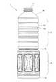
以下、本発明の実施例1について図面を参照しつつ、飲料や各種調味料用のボトルとして一般的な内容量を1リットルとするボトルを例に説明する。図1に示すように、ボトル1は、ボトル1内に調味料等の充填物を出し入れするための口部11と、口部11から上方胴部12へつながる肩部16と、ラベル等を貼り付けするための上方胴部12と、上方胴部12と下方胴部14との境界に環状に形成されるくびれ部13と、後述する減圧吸収パネル140が複数配置される下方胴部14と、底部15とからなる。以下、この図1における位置関係および方向に基づいて説明する。
Hereinafter, a first embodiment of the present invention will be described with reference to the drawings, taking as an example a bottle having a general content of 1 liter as a bottle for beverages and various seasonings. As shown in FIG. 1, the bottle 1 has a
上方胴部12は、上方胴部表面121と上方胴部表面121を上下方向に略等間隔に区分けするように形成されるものであって水平に環状に形成される環状溝122とからなる。この環状溝122の深さおよび間隔の長さは、ボトルの形状や大きさに基づいて適宜設定してよいが、深さ「0.5mm〜3mm」、間隔は「8mm〜30mm」の範囲で定めるとよい。 The
上方胴部12は、通常、商品の商品名等を消費者に示すためのプラスチックフィルム等によるラベルが付される部分であり、使用者がボトル1を使用する際に握ることが多い部分である。環状溝122が形成されることにより、ラベルの貼り付け作業や使用者が握った際にボトル1が受ける外圧に対する補強となるため、ボトル1の変形を防止することができる。また、ボトル1に高温の充填物を注入し密閉した際におけるボトル1内部の陽圧に対する抵抗にもなるので、この場合においてもボトル1の変形を防ぐことができる。この上方胴部12は、前記理由により所定長さが必要であるが、近年、商品アピール等、ボトルデザイン的な要素もあいまってボトル全体に占める長さがより長い(大きい)形状が求められている。 The
それに対し、下方胴部14は、前記上方胴部12が長くなった分、相対的に軸方向で短く形成されるようになり、長さが上方胴部の長さよりも短い形状になり、ボトルの内容量は変わらないため、発生する減圧はより狭い部分で吸収しなければならなくなった。本発明の1リットルボトルにおいては、ボトル全高が約260mmであって、上方胴部12の軸方向の長さが約102mmであるのに対し、減圧吸収パネルを形成する下方胴部14は約90mm(ボトル全高の約35%)と相対的に小さく、この小さい下方胴部で従来形状と同様の減圧を吸収することが求められている。 On the other hand, the
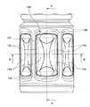
本発明に係る当該下方胴部14に形成される減圧吸収パネル140は、図2乃至図4に示すとおり、減圧吸収パネル140とその他の部分とを区画する区画枠141と、区画枠141に隣接するように形成されるボトル水平方向外側にやや張り出すように形成される膨部142と、当該膨部142と減圧吸収パネル140の略中央に位置する中央面145とを連結する連結面143とからなる。そして、図示されているように前記膨部142は、区画枠141の全周に沿って位置している。
As shown in FIGS. 2 to 4, the
図3および図4に示すように、膨部142の頂点Tは、区画枠141よりボトル外側に突出するように形成される。このように、減圧吸収パネル140は、その区画枠141から中央面145に向かって一旦ボトル外側に張り出してから連結面143および中央面145に至る形状となる。 As shown in FIGS. 3 and 4, a vertex T of the bulging
当該膨部142がなすボトル外側に張り出す形状により、陽圧吸収性能をより向上させることができる。すなわち、ボトル1内に高温の充填物が注入密封され、ボトル1内が陽圧状態となった場合、減圧吸収パネル140はその区画枠141を起点にボトル外側に膨出する。この際、膨部142が減圧吸収パネル140の膨出のための余地となるため、減圧吸収パネル140のボトル1外側への膨出量が増加するため、陽圧吸収性能を高めることができる。 The shape of the bulging
また、膨部142により減圧吸収パネル140の区画枠141を起点とする膨出に伴う減圧吸収パネル140の可動角度が抑えられる。これにより、陽圧時に膨出した減圧吸収パネル140が、減圧時に元の形状に戻りやすいため、陽圧時の形状を保持してしまい元の形状に戻らないといった不具合を起こりにくくすることができる。 In addition, the
減圧吸収パネル140の中央面145は、区画枠141よりもボトル水平方向内側に設けられる。中央面145と膨部142とを連結する連結面143は平面であってもよいし、ボトル外側にやや膨出させた球面状であってもよい。 The
以上のように、減圧吸収パネル140における各部の位置関係においては、最もボトル水平方向外側に位置するのが、膨部142の頂点Tであり、最もボトル水平方向内側に位置するのが中央面145である。これにより、膨部の142の頂点Tから中央面145に至るまでの連結面143等を含む部材を十分にとることができるので、陽圧および減圧時における減圧吸収パネル140の可動幅を十分にとることでき、陽圧および減圧吸収性能を高めることができる。 As described above, in the positional relationship between the components of the reduced-
また、このように、中央面145の位置を最もボトル水平方向内側に設けるため、減圧時に陽圧による膨出前の元の形状に戻りやすくなる。また、減圧時において、ボトル水平方向外側に張り出させた膨部142がボトル内側に引き込まれることにより、当該膨部142だけでも減圧吸収に役立つ。 In addition, since the position of the
ここで、略長方形の減圧吸収パネル140にあっては、特にその角部146付近において、陽圧時の膨出した形状が保持されてしまい、減圧状態になっても戻らないという形状不良が生じやすい。そこで、減圧吸収パネル140の角付近に膨部142を小さくすることにより、減圧吸収パネル140の角部146付近における陽圧時の膨出量を抑えることにより、形状不良の発生を防ぐ。
Here, in the case of the substantially rectangular
具体的には、図2に示したように、減圧吸収パネル140の四隅の各角部146の付近においては、膨出部142をその他の部分における幅より小さく設ける。また、中央面145を角部146に向けて延設する。
Specifically, as shown in FIG. 2, in the vicinity of each of the four
そして、中央面145と連結面143とが成す中央区画144を、減圧吸収パネル140の中心方向に円弧状に張り出す形状とする。さらに図2に示されているように、区画枠141の上下辺部分に沿う膨部142の中央部分のボトル上下方向での幅と区画枠141の左右辺部分に沿う膨部142の中央部分のボトル胴部周方向での幅とを、上記角部146近傍における膨部142の幅より大として、前記区画枠141の上下辺部分に沿う膨部142の中央部分と区画枠141の左右辺部分に沿う膨部142の中央部分とを、減圧吸収パネル140の中心側に向けて張り出る形状としている。これにより、減圧吸収パネル140の角部146付近以外の部分については、膨部142を十分に設けることにより適切な陽圧および減圧吸収性能を維持しながら、角部146においては膨出を抑え、かつ減圧時に角部146の形状を戻りやすくすることができる。Then , the
本発明に係る合成樹脂製ボトルについて、そのボトル全高の約35%の高さに限定した下方胴部14に縦長の略長方形状で長さ約65mmで幅約34mmの前記構成の減圧吸収パネル140を等間隔で周状に6面形成させたものに、従来ボトルと略同量の内容物を80〜90℃の加熱条件で充填した結果、80℃充填のボトル収縮量は0.9mlで、83℃充填のボトル収縮量は3.0ml、85℃充填のボトル収縮量は6.3ml、87℃充填ではボトル収縮量10.5ml、90℃充填においては、ボトル収縮量18.2mlという結果を得た。 With respect to the synthetic resin bottle according to the present invention, the
このように、本発明に係る合成樹脂製ボトルにおいては、優れた減圧吸収効果を示しており、ボトルの形状不良もなく好適な結果を得た。 Thus, in the synthetic resin bottle according to the present invention, an excellent vacuum absorption effect was exhibited, and favorable results were obtained without a bottle shape defect.
当該減圧吸収パネル140を利用する場合にあっては、口部11と、ラベル等を貼り付けするための上方胴部12と、当該口部11と上方胴部12を連結する肩部16と、上方胴部12と、上方胴部12と下方胴部14との境界に環状に形成されるくびれ部13と、当該減圧吸収パネル140が複数配置される下方胴部14と、底部15とからなり、ボトル全高を240〜280mm、内容量を700〜1500ミリリットルとするものであって、減圧吸収パネル140を4〜8個備え、下方胴部14の高さがボトル全高の30〜45%である合成樹脂製ペットボトルの場合にあって、特に好適である。 When using the
1 合成樹脂製ボトル
11 口部
12 上方胴部
13 くびれ部
14 下方胴部
15 底部
16 肩部
140 減圧吸収パネル
141 区画枠
142 膨部
143 連結面
144 中央区画
145 中央面
146 角部DESCRIPTION OF SYMBOLS 1
Claims (2)
Translated fromJapanese前記膨部(142)は、前記区画枠(141)の全周に沿って位置していて、
前記減圧吸収パネル(140)の角部(146)近傍における膨部(142)の幅を、前記角部(146)近傍の他の部分における前記膨部(142)の幅より狭くして、前記中央面(145)が前記角部(146)に向けて延設され、
前記区画枠(141)の上下辺部分に沿う膨部(142)の中央部分のボトル上下方向での幅と区画枠(141)の左右辺部分に沿う膨部(142)の中央部分のボトル胴部周方向での幅とを、前記角部(146)近傍における膨部(142)の幅より大として、前記区画枠(141)の上下辺部分に沿う膨部(142)の中央部分と区画枠(141)の左右辺部分に沿う膨部(142)の中央部分とが、減圧吸収パネル(140)の中心側に向けて張り出る形状とされていることを特徴とする合成樹脂製ボトル。In the synthetic resin bottle(1) having a vacuum panels(140) to absorb the reduced pressure in the bottle, the vacuum panels(140), said vacuum panels and a said vacuum panels(140) on the( 140), and a bulging portion(142) formed so that its apex(T) is located outside the bottle in thehorizontal direction ofthe partition frame(141) that separates the other portion from the partition frame(141). A central surface(145) formed inward in the direction and substantially at the center of the decompression absorption panel(140) , and a connecting surface(143) connecting the bulging portion(142) and the central surface(145). DoRi,
The bulging portion (142) is located along the entire circumference of the partition frame (141),
The width of the bulge (142) in the vicinity of the corner (146) of the decompression absorption panel (140) is made smaller than the width of the bulge (142) in the other part near the corner (146). A central surface (145) extends toward the corner (146);
The width of the central portion of the bulging portion (142) along the upper and lower sides of the partition frame (141) in the vertical direction of the bottle and the bottle body of the central portion of the bulging portion (142) along the left and right sides of the partition frame (141). The width in the circumferential direction is larger than the width of the bulge (142) in the vicinity of the corner (146), and the central part of the bulge (142) along the upper and lower sides of the partition frame (141) and the partition A synthetic resin bottle characterized in that acentral portion of a bulging portion (142) along left and right sides of a frame (141) is shaped to protrude toward a center side of a reduced-pressure absorbing panel (140) .
It is made of polyethylene terephthalate resin and has a mouth part(11) , a shoulder part(16) , an upper body part(12) , a constriction part(13) , a lower body part(14) , a bottom part(15) , and a height. Of the 240 to 280 mm, the height of the lower body(14) is 30 to 45% of the height of the bottle, and the six lower pressure absorbing panels(140) are circumferentially provided on the lower body(14). The synthetic resin bottle according to claim1 , wherein the bottle is formed at substantially equal intervals.
Priority Applications (1)
| Application Number | Priority Date | Filing Date | Title |
|---|---|---|---|
| JP2015173840AJP6671896B2 (en) | 2015-09-03 | 2015-09-03 | Synthetic resin bottle |
Applications Claiming Priority (1)
| Application Number | Priority Date | Filing Date | Title |
|---|---|---|---|
| JP2015173840AJP6671896B2 (en) | 2015-09-03 | 2015-09-03 | Synthetic resin bottle |
Publications (2)
| Publication Number | Publication Date |
|---|---|
| JP2017047953A JP2017047953A (en) | 2017-03-09 |
| JP6671896B2true JP6671896B2 (en) | 2020-03-25 |
Family
ID=58279050
Family Applications (1)
| Application Number | Title | Priority Date | Filing Date |
|---|---|---|---|
| JP2015173840AActiveJP6671896B2 (en) | 2015-09-03 | 2015-09-03 | Synthetic resin bottle |
Country Status (1)
| Country | Link |
|---|---|
| JP (1) | JP6671896B2 (en) |
Family Cites Families (6)
| Publication number | Priority date | Publication date | Assignee | Title |
|---|---|---|---|---|
| JP2949459B2 (en)* | 1993-11-05 | 1999-09-13 | 株式会社吉野工業所 | Hollow container made of polyethylene terephthalate resin |
| US5740934A (en)* | 1995-09-18 | 1998-04-21 | Plastic Technologies, Inc. | Container with vertical stiffening in central panel |
| US7198164B2 (en)* | 2003-03-31 | 2007-04-03 | Graham Packaging Company, L.P. | Hot-fillable container with a waisted dome |
| JP4749952B2 (en)* | 2006-06-29 | 2011-08-17 | 株式会社吉野工業所 | Bottle |
| JP5986733B2 (en)* | 2011-10-31 | 2016-09-06 | 株式会社吉野工業所 | Bottle |
| JP6175998B2 (en)* | 2013-09-02 | 2017-08-09 | 三菱ケミカル株式会社 | Plastic bottle |
- 2015
- 2015-09-03JPJP2015173840Apatent/JP6671896B2/enactiveActive
Also Published As
| Publication number | Publication date |
|---|---|
| JP2017047953A (en) | 2017-03-09 |
Similar Documents
| Publication | Publication Date | Title |
|---|---|---|
| JP5057306B2 (en) | Synthetic resin housing | |
| KR101267463B1 (en) | Synthetic resin bottle body | |
| JP6713215B2 (en) | Synthetic resin container | |
| JP2017100743A (en) | Decompression absorption bottle | |
| JP5472792B2 (en) | Synthetic resin housing | |
| JP6150122B2 (en) | Synthetic resin round frame | |
| JP5700329B2 (en) | Synthetic resin round frame | |
| JP5207178B2 (en) | Synthetic resin square housing | |
| JP6678106B2 (en) | Resin container | |
| JP6671896B2 (en) | Synthetic resin bottle | |
| JP6249294B2 (en) | Synthetic resin round frame | |
| JP5397805B2 (en) | Synthetic resin round frame | |
| JP4887045B2 (en) | Plastic bottle | |
| JP5565683B2 (en) | Synthetic resin round frame | |
| JP6241719B2 (en) | Synthetic resin round frame | |
| JP6403392B2 (en) | Plastic bottle | |
| JP2008030822A (en) | Synthetic resin bottle equipped with pressure reducing/absorbing panel | |
| JP6651758B2 (en) | Synthetic resin container | |
| JP5966362B2 (en) | Plastic container | |
| JPWO2019093114A1 (en) | Synthetic resin container | |
| JP4689350B2 (en) | Polyethylene terephthalate resin housing | |
| JP6670573B2 (en) | A bottle with a panel formed on the body | |
| JP5689374B2 (en) | Plastic bottle | |
| JP2013136407A (en) | Synthetic resin vessel | |
| JP4986436B2 (en) | Synthetic resin bottle-type container with a vacuum absorbing panel |
Legal Events
| Date | Code | Title | Description |
|---|---|---|---|
| A621 | Written request for application examination | Free format text:JAPANESE INTERMEDIATE CODE: A621 Effective date:20180828 | |
| A977 | Report on retrieval | Free format text:JAPANESE INTERMEDIATE CODE: A971007 Effective date:20190627 | |
| A131 | Notification of reasons for refusal | Free format text:JAPANESE INTERMEDIATE CODE: A131 Effective date:20190709 | |
| A521 | Request for written amendment filed | Free format text:JAPANESE INTERMEDIATE CODE: A523 Effective date:20190904 | |
| TRDD | Decision of grant or rejection written | ||
| A01 | Written decision to grant a patent or to grant a registration (utility model) | Free format text:JAPANESE INTERMEDIATE CODE: A01 Effective date:20200225 | |
| A61 | First payment of annual fees (during grant procedure) | Free format text:JAPANESE INTERMEDIATE CODE: A61 Effective date:20200304 | |
| R150 | Certificate of patent or registration of utility model | Ref document number:6671896 Country of ref document:JP Free format text:JAPANESE INTERMEDIATE CODE: R150 | |
| R250 | Receipt of annual fees | Free format text:JAPANESE INTERMEDIATE CODE: R250 | |
| R250 | Receipt of annual fees | Free format text:JAPANESE INTERMEDIATE CODE: R250 | |
| R250 | Receipt of annual fees | Free format text:JAPANESE INTERMEDIATE CODE: R250 |