JP6671859B2 - End effector force measurement drive circuit - Google Patents
End effector force measurement drive circuitDownload PDFInfo
- Publication number
- JP6671859B2 JP6671859B2JP2015088456AJP2015088456AJP6671859B2JP 6671859 B2JP6671859 B2JP 6671859B2JP 2015088456 AJP2015088456 AJP 2015088456AJP 2015088456 AJP2015088456 AJP 2015088456AJP 6671859 B2JP6671859 B2JP 6671859B2
- Authority
- JP
- Japan
- Prior art keywords
- assembly
- adapter
- loading unit
- surgical instrument
- surgical
- Prior art date
- Legal status (The legal status is an assumption and is not a legal conclusion. Google has not performed a legal analysis and makes no representation as to the accuracy of the status listed.)
- Active
Links
- 239000012636effectorSubstances0.000titleclaimsdescription38
- 238000005259measurementMethods0.000titleclaimsdescription20
- 238000012937correctionMethods0.000claimsdescription16
- 239000004020conductorSubstances0.000claimsdescription7
- 230000033228biological regulationEffects0.000claimsdescription6
- 238000012976endoscopic surgical procedureMethods0.000claimsdescription6
- 238000001914filtrationMethods0.000claimsdescription5
- 230000001629suppressionEffects0.000claimsdescription3
- 239000000758substrateSubstances0.000description35
- 238000000034methodMethods0.000description24
- 230000007246mechanismEffects0.000description21
- 238000010200validation analysisMethods0.000description20
- 238000010304firingMethods0.000description18
- 238000004891communicationMethods0.000description11
- 238000004519manufacturing processMethods0.000description7
- 238000012795verificationMethods0.000description5
- 230000000712assemblyEffects0.000description4
- 238000000429assemblyMethods0.000description4
- 230000005540biological transmissionEffects0.000description4
- 230000008878couplingEffects0.000description4
- 238000010168coupling processMethods0.000description4
- 238000005859coupling reactionMethods0.000description4
- 238000001356surgical procedureMethods0.000description4
- 230000006835compressionEffects0.000description3
- 238000007906compressionMethods0.000description3
- 238000010586diagramMethods0.000description3
- 230000006870functionEffects0.000description3
- 238000009434installationMethods0.000description3
- PXHVJJICTQNCMI-UHFFFAOYSA-NNickelChemical compound[Ni]PXHVJJICTQNCMI-UHFFFAOYSA-N0.000description2
- 230000008901benefitEffects0.000description2
- 239000012530fluidSubstances0.000description2
- 239000000463materialSubstances0.000description2
- 229910052751metalInorganic materials0.000description2
- 239000002184metalSubstances0.000description2
- 230000008569processEffects0.000description2
- 230000002829reductive effectEffects0.000description2
- 229910000679solderInorganic materials0.000description2
- 239000000126substanceSubstances0.000description2
- HBBGRARXTFLTSG-UHFFFAOYSA-NLithium ionChemical compound[Li+]HBBGRARXTFLTSG-UHFFFAOYSA-N0.000description1
- 230000003213activating effectEffects0.000description1
- 230000004913activationEffects0.000description1
- 239000000853adhesiveSubstances0.000description1
- 230000001070adhesive effectEffects0.000description1
- 239000000956alloySubstances0.000description1
- 229910045601alloyInorganic materials0.000description1
- DMFGNRRURHSENX-UHFFFAOYSA-Nberyllium copperChemical compound[Be].[Cu]DMFGNRRURHSENX-UHFFFAOYSA-N0.000description1
- 210000000941bileAnatomy0.000description1
- 239000008280bloodSubstances0.000description1
- 210000004369bloodAnatomy0.000description1
- 239000002131composite materialSubstances0.000description1
- 230000001010compromised effectEffects0.000description1
- 238000005520cutting processMethods0.000description1
- 238000001514detection methodMethods0.000description1
- 230000005611electricityEffects0.000description1
- 238000007667floatingMethods0.000description1
- 239000000446fuelSubstances0.000description1
- 238000002347injectionMethods0.000description1
- 239000007924injectionSubstances0.000description1
- 239000011810insulating materialSubstances0.000description1
- 230000003993interactionEffects0.000description1
- 230000000670limiting effectEffects0.000description1
- 229910001416lithium ionInorganic materials0.000description1
- 230000007257malfunctionEffects0.000description1
- 150000002739metalsChemical class0.000description1
- 238000012986modificationMethods0.000description1
- 230000004048modificationEffects0.000description1
- 229910052759nickelInorganic materials0.000description1
- 230000036961partial effectEffects0.000description1
- 238000003825pressingMethods0.000description1
- 230000000717retained effectEffects0.000description1
- 238000007789sealingMethods0.000description1
- 239000004065semiconductorSubstances0.000description1
- 238000005476solderingMethods0.000description1
- 239000000243solutionSubstances0.000description1
- 238000003892spreadingMethods0.000description1
- 238000013519translationMethods0.000description1
- 238000003466weldingMethods0.000description1
Images


Classifications
- G—PHYSICS
- G01—MEASURING; TESTING
- G01L—MEASURING FORCE, STRESS, TORQUE, WORK, MECHANICAL POWER, MECHANICAL EFFICIENCY, OR FLUID PRESSURE
- G01L5/00—Apparatus for, or methods of, measuring force, work, mechanical power, or torque, specially adapted for specific purposes
- G01L5/0028—Force sensors associated with force applying means
- A—HUMAN NECESSITIES
- A61—MEDICAL OR VETERINARY SCIENCE; HYGIENE
- A61B—DIAGNOSIS; SURGERY; IDENTIFICATION
- A61B17/00—Surgical instruments, devices or methods
- A61B17/068—Surgical staplers, e.g. containing multiple staples or clamps
- A61B17/072—Surgical staplers, e.g. containing multiple staples or clamps for applying a row of staples in a single action, e.g. the staples being applied simultaneously
- A61B17/07207—Surgical staplers, e.g. containing multiple staples or clamps for applying a row of staples in a single action, e.g. the staples being applied simultaneously the staples being applied sequentially
- A—HUMAN NECESSITIES
- A61—MEDICAL OR VETERINARY SCIENCE; HYGIENE
- A61B—DIAGNOSIS; SURGERY; IDENTIFICATION
- A61B90/00—Instruments, implements or accessories specially adapted for surgery or diagnosis and not covered by any of the groups A61B1/00 - A61B50/00, e.g. for luxation treatment or for protecting wound edges
- A61B90/90—Identification means for patients or instruments, e.g. tags
- A61B90/98—Identification means for patients or instruments, e.g. tags using electromagnetic means, e.g. transponders
- G—PHYSICS
- G01—MEASURING; TESTING
- G01L—MEASURING FORCE, STRESS, TORQUE, WORK, MECHANICAL POWER, MECHANICAL EFFICIENCY, OR FLUID PRESSURE
- G01L1/00—Measuring force or stress, in general
- G01L1/20—Measuring force or stress, in general by measuring variations in ohmic resistance of solid materials or of electrically-conductive fluids; by making use of electrokinetic cells, i.e. liquid-containing cells wherein an electrical potential is produced or varied upon the application of stress
- G01L1/22—Measuring force or stress, in general by measuring variations in ohmic resistance of solid materials or of electrically-conductive fluids; by making use of electrokinetic cells, i.e. liquid-containing cells wherein an electrical potential is produced or varied upon the application of stress using resistance strain gauges
- A—HUMAN NECESSITIES
- A61—MEDICAL OR VETERINARY SCIENCE; HYGIENE
- A61B—DIAGNOSIS; SURGERY; IDENTIFICATION
- A61B17/00—Surgical instruments, devices or methods
- A61B2017/00017—Electrical control of surgical instruments
- A—HUMAN NECESSITIES
- A61—MEDICAL OR VETERINARY SCIENCE; HYGIENE
- A61B—DIAGNOSIS; SURGERY; IDENTIFICATION
- A61B17/00—Surgical instruments, devices or methods
- A61B2017/00367—Details of actuation of instruments, e.g. relations between pushing buttons, or the like, and activation of the tool, working tip, or the like
- A61B2017/00398—Details of actuation of instruments, e.g. relations between pushing buttons, or the like, and activation of the tool, working tip, or the like using powered actuators, e.g. stepper motors, solenoids
- A—HUMAN NECESSITIES
- A61—MEDICAL OR VETERINARY SCIENCE; HYGIENE
- A61B—DIAGNOSIS; SURGERY; IDENTIFICATION
- A61B17/00—Surgical instruments, devices or methods
- A61B2017/0046—Surgical instruments, devices or methods with a releasable handle; with handle and operating part separable
- A—HUMAN NECESSITIES
- A61—MEDICAL OR VETERINARY SCIENCE; HYGIENE
- A61B—DIAGNOSIS; SURGERY; IDENTIFICATION
- A61B17/00—Surgical instruments, devices or methods
- A61B2017/0046—Surgical instruments, devices or methods with a releasable handle; with handle and operating part separable
- A61B2017/00473—Distal part, e.g. tip or head
- A—HUMAN NECESSITIES
- A61—MEDICAL OR VETERINARY SCIENCE; HYGIENE
- A61B—DIAGNOSIS; SURGERY; IDENTIFICATION
- A61B17/00—Surgical instruments, devices or methods
- A61B17/068—Surgical staplers, e.g. containing multiple staples or clamps
- A61B17/072—Surgical staplers, e.g. containing multiple staples or clamps for applying a row of staples in a single action, e.g. the staples being applied simultaneously
- A61B2017/07214—Stapler heads
- A61B2017/07278—Stapler heads characterised by its sled or its staple holder
- A—HUMAN NECESSITIES
- A61—MEDICAL OR VETERINARY SCIENCE; HYGIENE
- A61B—DIAGNOSIS; SURGERY; IDENTIFICATION
- A61B90/00—Instruments, implements or accessories specially adapted for surgery or diagnosis and not covered by any of the groups A61B1/00 - A61B50/00, e.g. for luxation treatment or for protecting wound edges
- A61B90/06—Measuring instruments not otherwise provided for
- A61B2090/064—Measuring instruments not otherwise provided for for measuring force, pressure or mechanical tension
Landscapes
- Health & Medical Sciences (AREA)
- Life Sciences & Earth Sciences (AREA)
- Surgery (AREA)
- General Health & Medical Sciences (AREA)
- Veterinary Medicine (AREA)
- Biomedical Technology (AREA)
- Heart & Thoracic Surgery (AREA)
- Medical Informatics (AREA)
- Molecular Biology (AREA)
- Animal Behavior & Ethology (AREA)
- Nuclear Medicine, Radiotherapy & Molecular Imaging (AREA)
- Public Health (AREA)
- Engineering & Computer Science (AREA)
- Physics & Mathematics (AREA)
- General Physics & Mathematics (AREA)
- Electromagnetism (AREA)
- Oral & Maxillofacial Surgery (AREA)
- Pathology (AREA)
- Chemical & Material Sciences (AREA)
- Analytical Chemistry (AREA)
- Surgical Instruments (AREA)
Description
Translated fromJapanese 関連出願の引用
本願は、2014年5月5日に出願された米国仮特許出願第61/988,342号の利益および優先権を主張する。この米国仮特許出願の全開示は、本明細書中に参考として援用される。REFERENCE TO RELATED APPLICATIONS This application claims the benefit and priority of US Provisional Patent Application No. 61 / 988,342, filed May 5, 2014. The entire disclosure of this US provisional patent application is incorporated herein by reference.
背景
1. 技術分野
本開示は、再使用可能なハンドルアセンブリ、および取り外し可能かつ交換可能な構成要素を有する、外科手術用デバイスに関する。より特定すると、本開示は、ファスナーを付けるための外科手術用器具において使用するために適したエンドエフェクタ力測定駆動回路に関する。
2. 関連技術の考察
内視鏡手順において使用するための動力式外科手術用器具は、公知である。代表的に、このような器具は、再使用可能なハンドルアセンブリ、および交換可能でありかつ一般的に使い捨てである構成要素(時々、単回使用装填ユニットまたはSULUと称される)を備える。アダプタアセンブリが、この装填ユニット(これは、組織と相互作用するためのエンドエフェクタを備え得る)をこのハンドルアセンブリに接続する。外科手術用ステープラーの場合、このエンドエフェクタは、交換可能なカートリッジを備え得、この交換可能なカートリッジは、この外科手術用ステープラーの発射ごとに交換される。費用を削減し、手順時間を短縮するために、これらのハンドルアセンブリは一般に、異なる特性(例えば、厚さおよび密度)を有する組織に対して使用するために、種々の装填ユニットおよび/または種々の構成のアセンブリと一緒に使用されるように構成される。例えば、異なる装填ユニットは、異なるサイズのステープルを有し得、そして/またはこれらのステープルは、異なる構成で配置され得る。このハンドルアセンブリがそれに取り付けられた装填ユニットと一緒に作動するようにプログラムされることを確実にするために、いくつかの装填ユニットは、集積回路(チップとしても公知)を備え、この回路は、このハンドルアセンブリと通信して、この装填ユニットの構成を識別する。この配置は、この装填ユニットをこのアダプタアセンブリに取り付けるときに、この装填ユニットの構成がこのハンドルアセンブリに自動的に伝えられることを可能にし、これによって、異なる構成を有する装填ユニットの間での切り替えのときに起こり得る、ユーザエラーまたは不一致を排除する。2. 2. Discussion of the Related Art Powered surgical instruments for use in endoscopic procedures are known. Typically, such devices include a reusable handle assembly and a replaceable and generally disposable component (sometimes referred to as a single use loading unit or SULU). An adapter assembly connects the loading unit, which may include an end effector for interacting with tissue, to the handle assembly. In the case of a surgical stapler, the end effector may include a replaceable cartridge, which is replaced with each firing of the surgical stapler. In order to reduce costs and reduce procedural time, these handle assemblies are generally adapted for use with tissues having different properties (eg, thickness and density) with different loading units and / or different loading units. Configured for use with the assembly of the component. For example, different loading units may have different sizes of staples and / or these staples may be arranged in different configurations. To ensure that the handle assembly is programmed to work with a loading unit attached to it, some loading units include an integrated circuit (also known as a chip), Communication with the handle assembly identifies the configuration of the loading unit. This arrangement allows the configuration of the loading unit to be automatically communicated to the handle assembly when the loading unit is attached to the adapter assembly, thereby switching between loading units having different configurations. Eliminate possible user errors or inconsistencies when
外科手術用ステープラーは一般に、体腔内の組織をステープル留めするために使用され、ここでエンドエフェクタはおそらく、流体(例えば、血液、胆汁および/または洗浄溶液)と接触する。チップとハンドルアセンブリとの間の相互接続が損なわれる場合、このチップが誤作動し得るか、または装填ユニットとハンドルアセンブリとの間のデータ通信が妨害され得、この外科手術用ステープラーが使用不可能または作動不可能になり得る。 Surgical staplers are commonly used for stapling tissue in body cavities, where the end effector is likely to be in contact with a fluid (eg, blood, bile and / or lavage solution). If the interconnect between the tip and the handle assembly is compromised, the tip may malfunction or data communication between the loading unit and the handle assembly may be interrupted, making the surgical stapler unusable Or it may become inoperable.
プリント回路基板(PCB)(時々、プリント配線板(PWB)または食刻配線板と称される)は、別個の電気構成要素を作動回路に組み立てる際に、広く使用されている。PCBは一般に、システム構成要素間で電気信号を相互接続する、信頼性のある経済的な手段を提供する。PCBは、種々の異なる型で入手可能であり、そして種々の方法で分類され得る。 Printed circuit boards (PCBs), sometimes referred to as printed wiring boards (PWBs) or etched wiring boards, are widely used in assembling discrete electrical components into working circuits. PCBs generally provide a reliable and economical means of interconnecting electrical signals between system components. PCBs are available in a variety of different types and can be classified in a variety of ways.
PCBは一般に、このPCB上で信号を伝導する導電性経路または信号トレースを使用して、電子構成要素を機械的に支持し、そして電気的に接続するために使用される。代表的なPCBは、1層または1層より多くの絶縁材料を備え、この上に、導電体のパターンが形成される。PCB上の伝導性トレースのパターンに加えて、金属を充填されたスルーホール(すなわち、バイア)のパターン付けされたアレイが形成されて、種々の電導性特徴にまたがる層間の相互接続を可能にし得る。上に電気構成要素が設置されるPCBは、時々、プリント回路組立品(PCA)またはプリント回路基板組立品(PCBA)と称される。 PCBs are commonly used to mechanically support and electrically connect electronic components using conductive paths or signal traces that conduct signals on the PCB. A typical PCB comprises one or more layers of insulating material upon which a pattern of conductors is formed. In addition to the pattern of conductive traces on the PCB, a patterned array of metal-filled through-holes (ie, vias) may be formed to enable interconnection between layers across various conductive features. . The PCB on which the electrical components are located is sometimes referred to as a printed circuit assembly (PCA) or printed circuit board assembly (PCBA).
PCBを使用する様々な種類の電気外科手術用デバイスが、薄く、そして/または小型になっている。いくつかのデバイスにおいて、これらのPCBを収容するために必要とされる空間量は、これらのデバイスのサイズを減少させることを困難にし得る。いくつかの場合において、所望の機能および/または性能を提供するために必要とされる電気構成要素を収容するために充分に大きいPCBレイアウトは、このデバイスの全体的なサイズを増大させ得、そして潜在的に、有用性を妨害し得る。 Various types of electrosurgical devices that use PCBs are becoming thinner and / or smaller. In some devices, the amount of space required to accommodate these PCBs can make it difficult to reduce the size of these devices. In some cases, a PCB layout that is large enough to accommodate the electrical components needed to provide the desired functionality and / or performance may increase the overall size of the device, and Potentially, it can hinder its usefulness.
電気信号は、PCB上で、組織への外科手術用ステープルの送達を制御するために使用され得る。ステープル、クリップ、または他のファスナーを組織に付けるための外科手術用デバイスは、周知である。外科手術用ファスナーを付けるための内視鏡外科手術用デバイスは、このデバイスを起動するための起動ユニット、すなわちハンドルアセンブリ、および内視鏡アクセスのためのシャフト、およびこのシャフトの遠位端に配置されたエンドエフェクタアセンブリを備える。これらのデバイスのうちの特定のものは、エンドエフェクタアセンブリを備えてステープルまたはファスナーを収容する交換可能な装填ユニットと一緒に使用するために、設計される。この交換可能な装填ユニットは、種々のサイズのステープルを備え得、そしてこれらのステープルは、1つまたは1つより多くの構成で配置され得る。交換可能な装填ユニットを備えるステープラーを発射させた後に、ユーザは、その空の装填ユニットを取り外し得、別の装填ユニット(同じサイズまたは異なるサイズのステープル、および同じステープル配置または異なるステープル配置を有する)を選択してこのステープラーに取り付け得、そしてこのステープラーを再度発射させ得る。このプロセスは、外科手術手順中に繰り返し行われ得る。 The electrical signal can be used on the PCB to control the delivery of surgical staples to the tissue. Surgical devices for applying staples, clips, or other fasteners to tissue are well known. An endoscopic surgical device for attaching a surgical fastener is provided with an activation unit for activating the device, i.e., a handle assembly, and a shaft for endoscopic access, and disposed at a distal end of the shaft. End effector assembly. Certain of these devices are designed for use with interchangeable loading units that contain staples or fasteners with an end effector assembly. The interchangeable loading unit may include staples of various sizes, and the staples may be arranged in one or more than one configuration. After firing the stapler with the replaceable loading unit, the user can remove the empty loading unit and another loading unit (having the same or different size staples and the same or different staple configurations) Can be attached to the stapler and the stapler can be fired again. This process may be performed repeatedly during the surgical procedure.
外科手術手順中に、このエンドエフェクタアセンブリが組織を締め付けているとき、または発射しているとき、いくつかの状況において、このエンドエフェクタアセンブリがカートリッジの一部に当たっているか否かが不明確であり得、そして外科医は、自分がさらに進めたいのか否かが不確実であり得る。いくつかの場合において、このエンドエフェクタアセンブリが、その発射を妨げるもの、またはモータ駆動が打ち勝つ必要があるものにあたっている場合、この器具は、過剰な電流を消費し、この電流が検出および測定され得る。しかし、エンドエフェクタアセンブリが別のステープル線に当たっている場合、または形成され損なった一連のステープルに遭遇している場合などに、モータ電流の測定値は、完全には信頼できないかもしれない。 During a surgical procedure, when the end effector assembly is pinching or firing tissue, in some situations it may be unclear whether the end effector assembly strikes a portion of a cartridge. And the surgeon may be uncertain whether he wants to go further. In some cases, if the end effector assembly is hitting something that prevents its firing, or that the motor drive needs to overcome, the instrument consumes excessive current, which can be detected and measured . However, measurements of motor current may not be completely reliable, such as when the end effector assembly is striking another staple line or encountering a series of staples that have failed to form.
本発明は、例えば、以下を提供する:
(項目1)
ファスナーを付けるための外科手術用器具であって、
駆動モータ;
エンドエフェクタアセンブリを有する交換可能な装填ユニット;および
該交換可能な装填ユニットを該駆動モータに解放可能に連結するように構成されたアダプタであって、該アダプタは、駆動回路が連結されたひずみゲージを備え、該ひずみゲージと該駆動回路とは、該アダプタにおける駆動力を直接測定するように構成されている、アダプタ
を備える、外科手術用器具。
(項目2)
上記駆動回路は、マイクロプロセッサおよび演算増幅器を備える、上記項目に記載の外科手術用器具。
(項目3)
上記演算増幅器は、低域フィルタリングを提供するように構成されている、上記項目のいずれかに記載の外科手術用器具。
(項目4)
上記演算増幅器は二極バターワースフィルタである、上記項目のいずれかに記載の外科手術用器具。
(項目5)
上記演算増幅器は、電磁気干渉(EMI)抑制を提供するように構成されている、上記項目のいずれかに記載の外科手術用器具。
(項目6)
傾き補正因子およびオフセット補正因子を含めた工場較正力測定値が、上記マイクロプロセッサに永続的に格納されている、上記項目のいずれかに記載の外科手術用器具。
(項目7)
上記駆動回路は、3.3ボルトのDC電圧を提供するように構成された電圧調整回路をさらに備える、上記項目のいずれかに記載の外科手術用器具。
(項目8)
上記演算増幅器のアナログ出力を上記マイクロプロセッサのアナログ−デジタル入力に伝送するように構成された導体をさらに備える、上記項目のいずれかに記載の外科手術用器具。
(項目9)
上記エンドエフェクタアセンブリは、ステープルを組織に付けるように構成されている、上記項目のいずれかに記載の外科手術用器具。
(項目10)
上記エンドエフェクタアセンブリは、内視鏡外科手術手順において使用するために構成されている、上記項目のいずれかに記載の外科手術用器具。
(項目11)
外科手術用デバイスにおける駆動力を測定する方法であって、
ファスナーを付けるための外科手術用器具を提供する工程であって、該外科手術用器具は、エンドエフェクタアセンブリを有する交換可能な装填ユニットを駆動モータに解放可能に連結するように構成されたアダプタを備え、該アダプタは、駆動回路に連結された、過剰な負荷を検出することが可能なひずみゲージを備える、工程;ならびに
該ひずみゲージおよび該駆動回路を使用して、該アダプタにおける駆動力を直接測定し、力測定値を得る工程
を包含する、方法。
(項目12)
上記力測定値に基づいて、過剰な負荷が検出されたことが決定される場合、上記アダプタに対する損傷を防止するように上記駆動力を調節する工程をさらに包含する、上記項目に記載の方法。
(項目13)
上記駆動回路の演算増幅器を使用して、信号に対する低域フィルタリングを行う工程をさらに包含する、上記項目のいずれかに記載の方法。
(項目14)
上記演算増幅器のアナログ出力を上記駆動回路のマイクロプロセッサのアナログ−デジタル入力に伝送する工程をさらに包含する、上記項目のいずれかに記載の方法。
(項目15)
上記エンドエフェクタアセンブリを使用してステープルを付ける工程をさらに包含する、上記項目のいずれかに記載の方法。
(項目16)
上記エンドエフェクタアセンブリを内視鏡外科手術手順において利用する工程をさらに包含する、上記項目のいずれかに記載の方法。
(項目17)
上記駆動回路の電圧調整回路を使用して、3.3ボルトのDC電圧を提供する工程をさらに包含する、上記項目のいずれかに記載の方法。
(項目18)
傾き補正因子およびオフセット補正因子を適用する工程をさらに包含する、上記項目のいずれかに記載の方法。
(項目19)
上記傾き補正因子およびオフセット補正因子は、上記マイクロプロセッサに永続的に格納されている、上記項目のいずれかに記載の方法。The present invention provides, for example:
(Item 1)
A surgical instrument for attaching a fastener,
Drive motor;
A replaceable loading unit having an end effector assembly; and an adapter configured to releasably connect the replaceable loading unit to the drive motor, the adapter comprising a strain gauge to which a drive circuit is coupled. A surgical instrument comprising an adapter, wherein the strain gauge and the drive circuit are configured to directly measure a driving force at the adapter.
(Item 2)
The surgical instrument of any preceding item, wherein the drive circuit comprises a microprocessor and an operational amplifier.
(Item 3)
The surgical instrument of any of the preceding items, wherein the operational amplifier is configured to provide low pass filtering.
(Item 4)
The surgical instrument according to any of the preceding items, wherein the operational amplifier is a bipolar Butterworth filter.
(Item 5)
The surgical instrument of any of the preceding items, wherein the operational amplifier is configured to provide electromagnetic interference (EMI) suppression.
(Item 6)
The surgical instrument of any of the preceding items, wherein factory calibration force measurements, including tilt correction factors and offset correction factors, are permanently stored in the microprocessor.
(Item 7)
The surgical instrument of any of the preceding items, wherein the drive circuit further comprises a voltage regulation circuit configured to provide a 3.3 volt DC voltage.
(Item 8)
The surgical instrument of any of the preceding items, further comprising a conductor configured to transmit an analog output of the operational amplifier to an analog-digital input of the microprocessor.
(Item 9)
The surgical instrument of any of the preceding items, wherein the end effector assembly is configured to apply staples to tissue.
(Item 10)
The surgical instrument of any of the preceding items, wherein the end effector assembly is configured for use in an endoscopic surgical procedure.
(Item 11)
A method for measuring a driving force in a surgical device, comprising:
Providing a surgical instrument for fasteners, the surgical instrument including an adapter configured to releasably connect a replaceable loading unit having an end effector assembly to a drive motor. The adapter comprising a strain gauge coupled to a drive circuit and capable of detecting excessive load; and using the strain gauge and the drive circuit to directly drive a drive force on the adapter. Measuring and obtaining a force measurement.
(Item 12)
The method of any preceding item, further comprising, if it is determined based on the force measurement that excessive load has been detected, adjusting the driving force to prevent damage to the adapter.
(Item 13)
The method of any of the preceding items, further comprising performing low-pass filtering on the signal using the operational amplifier of the drive circuit.
(Item 14)
The method of any of the preceding items, further comprising transmitting an analog output of the operational amplifier to an analog-digital input of a microprocessor of the drive circuit.
(Item 15)
The method of any of the preceding items, further comprising applying staples using the end effector assembly.
(Item 16)
The method of any of the preceding items, further comprising utilizing the end effector assembly in an endoscopic surgical procedure.
(Item 17)
The method of any of the preceding items, further comprising providing a 3.3 volt DC voltage using the voltage regulation circuit of the drive circuit.
(Item 18)
The method according to any of the preceding items, further comprising applying a tilt correction factor and an offset correction factor.
(Item 19)
The method of any of the preceding items, wherein the tilt correction factor and the offset correction factor are permanently stored in the microprocessor.
摘要
ファスナーを付けるための外科手術用器具は、駆動モータ、エンドエフェクタアセンブリを有する交換可能な装填ユニット、および交換可能な装填ユニットをこの駆動モータに解放可能に連結するように構成されたアダプタを備える。このアダプタは、駆動回路が連結されたひずみゲージを備える。このひずみゲージとこの駆動回路とは、このアダプタにおける駆動力を直接測定するように構成される。SUMMARY A surgical instrument for attaching a fastener includes a drive motor, a replaceable loading unit having an end effector assembly, and an adapter configured to releasably connect the replaceable loading unit to the drive motor. . The adapter includes a strain gauge to which a drive circuit is connected. The strain gauge and the drive circuit are configured to directly measure the driving force at the adapter.
要旨
本開示の局面によれば、ファスナーを付けるための外科手術用器具が提供され、この外科手術用器具は、駆動モータ、エンドエフェクタアセンブリを有する交換可能な装填ユニット、およびこの交換可能な装填ユニットをこの駆動モータに解放可能に連結するように構成されたアダプタを備える。このアダプタは、駆動回路が連結されたひずみゲージを備える。このひずみゲージとこの駆動回路とは、このアダプタにおける駆動力を直接測定するように構成される。SUMMARY According to an aspect of the present disclosure, there is provided a surgical instrument for fastening, the surgical instrument includes a drive motor, an exchangeable loading unit having an end effector assembly, and the exchangeable loading unit. And an adapter configured to releasably connect to the drive motor. The adapter includes a strain gauge to which a drive circuit is connected. The strain gauge and the drive circuit are configured to directly measure the driving force at the adapter.
本開示の別の局面によれば、外科手術用デバイスにおける駆動力を測定する方法は、ファスナーを付けるための外科手術用器具を提供する工程を包含し、この外科手術用器具は、エンドエフェクタアセンブリを有する交換可能な装填ユニットを駆動モータに解放可能に連結するように構成されたアダプタを備える。このアダプタは、過剰な負荷を検出することが可能な、駆動回路に連結されたひずみゲージを備える。この方法はまた、このひずみゲージおよびこの駆動回路を使用して、このアダプタにおける駆動力を直接測定し、力測定値を得る工程、ならびにこの力測定値に基づいて、過剰な負荷が検出されたことが決定される場合、このアダプタに対する損傷を防止するように、この駆動力を調節する工程を包含する。 According to another aspect of the present disclosure, a method of measuring driving force in a surgical device includes providing a surgical instrument for fastening, the surgical instrument comprising an end effector assembly. And an adapter configured to releasably connect the replaceable loading unit having the to the drive motor. The adapter includes a strain gauge connected to a drive circuit that can detect excessive load. The method also includes directly measuring the driving force at the adapter using the strain gauge and the driving circuit to obtain a force measurement, and based on the force measurement, detecting an excessive load. If so, adjusting the driving force to prevent damage to the adapter is included.
前出の局面のうちのいずれか1つによれば、この駆動回路は、マイクロプロセッサを備え、そして傾き補正因子およびオフセット補正因子を含む工場較正力測定値が、この駆動回路のマイクロプロセッサに永続的に格納されている。前出の局面のうちのいずれか1つによれば、この駆動回路は、DC電圧を提供するように構成された電圧調整回路をさらに備える。 According to any one of the preceding aspects, the drive circuit comprises a microprocessor, and the factory calibration force measurements including the tilt correction factor and the offset correction factor are permanently stored in the microprocessor of the drive circuit. Is stored. According to any one of the preceding aspects, the drive circuit further comprises a voltage regulation circuit configured to provide a DC voltage.
本開示の上記および他の局面、特徴、および利点は、添付の図面と合わせて読まれる場合に、以下の詳細な説明を考慮すると、より明らかになる。 The above and other aspects, features and advantages of the present disclosure will become more apparent from the following detailed description when read in conjunction with the accompanying drawings.
詳細な説明
本明細書中以下で、ひずみゲージおよび駆動回路を備えて構成されたアダプタを備える本開示の外科手術用器具、ならびに外科手術用デバイスにおける駆動力を測定する方法の実施形態が、添付の図面を参照しながら記載される。同じ参照番号は、図面の説明全体にわたって、類似の要素または同一の要素をいい得る。本開示の特定の実施形態が、添付の図面を参照しながら本明細書中以下に記載されるが、開示される実施形態は、単に本開示の例であり、本開示は種々の形態で実施され得ることが、理解されるべきである。周知かつ/または繰り返しの機能および構成は、本開示を不必要または冗長な細部で曖昧にすることを回避するために、詳細に記載されない。従って、本明細書中に開示される特定の構造的細部および機能的細部は、限定であると解釈されるべきではなく、単に、特許請求の範囲の基礎として、および当業者が事実上任意の適切に詳述した構造で本開示を様々に実施するための教示の代表的な基礎として、解釈されるべきである。当該分野において一般的であるように、用語「近位」とは、ユーザまたは操作者(すなわち、外科医または医師)に近い方の部分または構成要素をいい、一方で、用語「遠位」とは、ユーザから遠い方の部分または構成要素をいう。さらに、説明および特許請求の範囲において本明細書中で使用される場合、方向に言及する用語(例えば、「頂」、「底」、「上」、「下」、「左」、および「右」など)は、本明細書中に図示および記載される図面および特徴を参照して使用される。本開示による実施形態は、制限なしで任意の配向で実施され得ることが理解されるべきである。本明細書および図面において、同じ参照番号は、同じ機能、類似の機能、または等価な機能を実施し得る要素を表す。本開示のチップアセンブリの実施形態が、ここで図面を参照しながら詳細に記載され、図面において、同じ参照番号は、数枚の図の各々において、同一の要素または対応する要素を表す。用語「例示的な」とは、本明細書中で、「実施例、実例、または説明として働くこと」を意味するように使用される。本明細書中に記載される任意の実施形態において、「例示的な」は必ずしも、他の実施形態より好ましいとも有利であるとも解釈される必要はない。用語「例」は、「例示的な」と交換可能に使用され得る。DETAILED DESCRIPTION Hereinafter, embodiments of the surgical instrument of the present disclosure comprising an adapter configured with a strain gauge and a drive circuit, and a method of measuring driving force in a surgical device, are described in the accompanying This will be described with reference to the drawings of FIG. Like reference numbers may refer to similar or identical elements throughout the description of the figures. While specific embodiments of the present disclosure are described herein below with reference to the accompanying drawings, the disclosed embodiments are merely examples of the present disclosure and the present disclosure may be embodied in various forms. It should be understood that this can be done. Well-known and / or repeated features and arrangements are not described in detail to avoid obscuring the present disclosure in unnecessary or redundant detail. Accordingly, the specific structural and functional details disclosed herein are not to be construed as limiting, but merely as a basis for the claims and by one of ordinary skill in the It should be construed as a representative basis for teaching variously practicing the present disclosure in an appropriately detailed structure. As is common in the art, the term "proximal" refers to the part or component that is closer to the user or operator (i.e., surgeon or physician), while the term "distal" , A part or a component farther from the user. Furthermore, as used herein in the description and claims, terms that refer to directions (eg, “top,” “bottom,” “top,” “bottom,” “left,” and “right” ]) Are used with reference to the drawings and features shown and described herein. It should be understood that embodiments according to the present disclosure can be implemented in any orientation without limitation. In the specification and drawings, the same reference number indicates an element that may perform the same function, a similar function, or an equivalent function. Embodiments of the presently disclosed chip assembly will now be described in detail with reference to the drawings, wherein like reference numbers represent the same or corresponding elements in each of the several figures. The term "exemplary" is used herein to mean "serving as an example, instance, or illustration." In any embodiment described herein, "exemplary" is not necessarily to be construed as preferred or advantageous over other embodiments. The term "example" may be used interchangeably with "exemplary."
本説明は、語句「1つの実施形態において」、「実施形態によっては」、「いくつかの実施形態において」、または「他の実施形態において」を使用し得る。これらはそれぞれ、本開示による同じ実施形態または異なる実施形態のうちの1つまたは1つより多くをいい得る。 This description may use the phrases "in one embodiment," "in some embodiments," "in some embodiments," or "in other embodiments." Each of these may refer to one or more of the same or different embodiments according to the present disclosure.
本明細書中で使用される場合、用語「電源」および「電力供給源」とは、任意の電力の供給源(例えば、コンセント、a/c発電機、バッテリまたはバッテリパックなど)をいう。本説明中で使用される場合、「導電性」、または単に「伝導性」とは、一般に、電気の伝導が可能である物質をいい、高電導性の物質(例えば、金属および合金)、または半伝導性の物質(例えば、半導体物質および複合材料)が挙げられるが、これらに限定されない。本説明中で使用される場合、「伝送線」とは、一般に、1つの点から別の点までの信号の伝搬のために使用され得る任意の伝送媒体をいう。 As used herein, the terms “power source” and “power source” refer to any source of power (eg, outlet, a / c generator, battery or battery pack, etc.). As used in this description, “conductive” or simply “conductive” generally refers to a substance capable of conducting electricity, a highly conductive substance (eg, metals and alloys), or Examples include, but are not limited to, semiconductive materials (eg, semiconductor materials and composite materials). As used in this description, "transmission line" generally refers to any transmission medium that can be used for the propagation of signals from one point to another.
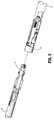
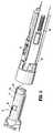
最初に図1および図2を参照すると、本開示による確証システムを備える外科手術用ステープル留め器具が、一般にステープラー10として示されている。ステープラー10は、ハンドルアセンブリ12、ハンドルアセンブリ12から遠位方向に延びるアダプタアセンブリ14、およびアダプタアセンブリ14の遠位端に選択的に固定される装填ユニット16を備える。ハンドルアセンブリ12、アダプタアセンブリ14、および装填ユニット16の詳細な説明は、共有に係る米国特許出願公開第2012/0089131号に提供されており、その内容は、その全体が本明細書中に参考として援用される。 Referring initially to FIGS. 1 and 2, a surgical stapling instrument with a validation system according to the present disclosure is shown generally as a
ハンドルアセンブリ12は、下ハウジング部分17、下ハウジング部分17から延びそして/または下ハウジング部分17上に支持される中間ハウジング部分18、および中間ハウジング部分18から延びそして/または中間ハウジング部分18上に支持される上ハウジング部分19を備える。中間ハウジング部分18と上ハウジング部分19とは、遠位半セクション20aと近位半セクション20bとに分離される。遠位半セクション20aは、下ハウジング部分17と一体的に形成され、そして下ハウジング部分17から延び、近位半セクション20bは、遠位半セクション20aに、任意の適切な取り付け方法(例えば、限定されないが、超音波溶接および/または複数の固定具)によって接合される。接合されると、遠位半セクション20aと近位半セクション20bとは、内部に空洞を規定するハンドルハウジング21を形成し、この空洞が、制御器21aを備える回路基板、および駆動機構(図示せず)を収容する。 The
下ハウジング部分17は、下ハウジング部分17内に形成された空洞にアクセスするためにそれに旋回可能に接続されたドア13を備える。この空洞は、バッテリ(図示せず)を内部に保持するためのものである。ステープラー10は、任意の数の電源(例えば、限定されないが、燃料電池、および外部電源に接続された電力コードなど)によって電力供給され得ることが想定される。 The
アダプタアセンブリ14は、その近位端にドライブ連結部22を備え、そしてその遠位端に装填ユニット連結部15を備える。上ハウジング部分19の遠位半セクション20aは、アダプタアセンブリ14のドライブ連結部22を作動可能に受容するように構成された、ノーズまたは接続部分11を規定する。装填ユニット16は、アダプタアセンブリ14の装填ユニット連結部15を作動可能に受容するように構成された、アダプタ連結部27を備える。 The
ハンドルハウジング21の上ハウジング部分19は、駆動機構(図示せず)を封入する。この駆動機構は、ステープラー10の種々の動作を実行する目的で、シャフトおよび/または歯車構成要素(図示せず)を駆動するように構成される。具体的には、この駆動機構は、装填ユニット16のツールアセンブリまたはエンドエフェクタ23を装填ユニット16の近位本体部分24に対して選択的に移動させる目的、装填ユニット16を長手方向軸「X−X」(図1)の周りでハンドルハウジング21に対して回転させる目的、アンビルアセンブリ25を装填ユニット16のカートリッジアセンブリ26に対して回転させる目的、ならびに/またはステープル留めおよび切断カートリッジを装填ユニット16のカートリッジアセンブリ26内で発射させる目的で、シャフトおよび/または歯車構成要素を駆動するように構成される。 The
図1〜図21に図示される装填ユニット16は、直線状外科手術用ステープル留め装填ユニットである。この装填ユニットは、外科手術用ステープルを形成するための凹部を有するステープル留めアンビルを備え、これらの外科手術用ステープルは、この外科手術用システムにおける装填ユニットの作動によって、このステープル留めアンビルに対して駆動される。ステープルカートリッジは、これらの外科手術用ステープル、ならびにステープル発射および/または駆動アセンブリを収容する。このステープル発射および/または駆動アセンブリは、公知である。1つのこのようなアセンブリは、米国特許第8,256,656号および同第7,044,353号に記載されており、これらの全開示は、本明細書中に参考として援用される。この駆動アセンブリは、ナイフ刃を有する細長駆動梁を備える。この駆動梁は、プッシャーと相互作用するための楔形の表面を有する起動そりを押す。これらのプッシャーは、これらのステープルを支持し、そしてカム作用表面を有する。このカム作用表面に対してそりの楔形表面がスライドし、このそりがステープルカートリッジを通って長手軸方向の様式で前進する間に、これらのプッシャーを上方に駆動する。 The
この装填ユニットは、このアンビルとこのステープルカートリッジとをそれぞれ支持するための、顎部材を有することが想定される。このアンビル顎部材およびこのステープルカートリッジ顎部材は、これらの間に組織をクランプするように、近接させられ得る。エンドエフェクタは、近位本体部分24によって規定される長手軸方向から軸をずらすように、関節運動または旋回し得ることもまた想定される。 It is assumed that the loading unit has a jaw member for supporting the anvil and the staple cartridge, respectively. The anvil jaw and the staple cartridge jaw may be approximated to clamp tissue therebetween. It is also envisioned that the end effector may be articulated or pivoted off-axis from the longitudinal direction defined by the
この装填ユニットは、円形外科手術用ステープル留めユニット、他の型のステープル留めユニット、または他の型の外科手術用エンドエフェクタ(例えば、電気メス、剥離、超音波など)であり得ることが想定される。 It is envisioned that the loading unit can be a circular surgical stapling unit, another type of stapling unit, or another type of surgical end effector (eg, electric scalpel, peel, ultrasonic, etc.). You.
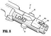
図3、図4、および図5を参照すると、アダプタアセンブリ14の装填ユニット連結部15は、装填ユニット16のアダプタ連結部27に、押して捩じる配置、または差し込み型の配置を介して作動可能に係合するように構成される。アダプタ連結部27は、1つまたは1つより多くの差し込みラグ28を備え、これらの差し込みラグは、アダプタアセンブリ14の装填ユニット連結部15により提供される差し込みカラー48に規定された、対応する1つまたは1つより多くの差し込みチャネル29と嵌合するように構成される。短いリンク部材44および装填リンク部材45は、アダプタアセンブリ14内に長手軸方向に配置され、そしてステープラー10の作動中に、長手軸方向に(例えば、遠位および近位に)並進するように構成される。短いリンク部材44の遠位端に配置されたカム55は、ばね49aによって遠位に推進されて差し込みチャネル29に押し付けられる。装填ユニット16をアダプタアセンブリ14と係合させるために、装填ユニット16のアダプタ連結部27は、アダプタアセンブリ14の装填ユニット連結部15に挿入され、そして回転させられる。次に、差し込みカラー48が、アダプタ連結部27と協働して回転する。差し込みカラー48が回転するにつれて、カム55が動いて差し込みチャネル29から外れ、短いリンク部材44を遠位方向に並進させ、これが次に、短いリンク部材44に形成されたスイッチタブ47にスイッチ46を起動させる。スイッチ46は、制御器21aと作動可能に電気通信しており、そしてこの制御器に装填ユニット16とアダプタアセンブリ14との間の係合状態を伝えるように構成される。 Referring to FIGS. 3, 4 and 5, the
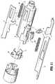
ここで図6〜図10を参照すると、装填ユニット16のアダプタ連結部27は、アダプタ連結部27に規定された凹部31内に固定されて設置されるように構成された、確証基板アセンブリ30を備える。確証基板アセンブリ30は、装填ユニット16がアダプタアセンブリ14に固定されているときに、確証基板アセンブリ30がアダプタアセンブリの装填ユニット連結部15内に設置されたアダプタ基板アセンブリ50(図11)に係合するように、アダプタ連結部27内に配置される。より詳細には、確証基板30は、回路基板37、1対の接触子部材40a、40b(まとめて、接触子部材40)、およびチップ36を備える。回路基板37は、アダプタ連結部27によって規定される凹部31内に固定されて受容されるように構成された、実質的に平坦な細長い部材を規定する。チップ36は、接触子部材40と電気通信する。回路基板37の遠位端37aはチップ36を支持し、そして回路基板37の近位端37bは接触子部材40を支持する。回路基板37の遠位端37aは、それに規定された整列用切欠き33を備え、この整列用切欠きは、凹部31の遠位端に提供された対応する整列用ナブ32と係合して、アダプタ連結部27内での確証基板アセンブリ30の固定された正確な配置を確実にするように構成される。 Referring now to FIGS. 6-10, the
チップ36は、装填ユニット16の仕様(例えば、限定されないが、カートリッジサイズ、ステープル配置、ステープル長さ、締め付け距離、製造日、使用期限、互換性特徴、独特の識別子(例えば、シリアルナンバー)、および/または使用回数)を格納すること、ならびにこれらの仕様をハンドルアセンブリ12に伝送することが可能な、任意のチップを備える。いくつかの実施形態において、チップ36は、消去可能再書込み可能読出し専用メモリ(「EPROM」)チップを備える。この方法で、ハンドルアセンブリ12は、チップ36から伝送される装填ユニット16の仕様に従って、このハンドルアセンブリの発射力、発射行程、および/または他の作動特徴を調節し得る。チップ36は、ハンドルアセンブリ12がチップ36に、関連する装填ユニット16が使用されたことを通信することを可能にする書込み能力を備え得、これにより、使い果たされたリロードアセンブリの再装填もしくは再使用、または他の任意の認可されない使用を防止し得ることがさらに想定される。 The
いくつかの実施形態において、チップ36は、セキュア確証チップ(例えば、限定されないが、1−Wire SHA−256および512−Bit User EEPROMを備えるDS28E15 DeepCoverTM Secure Authenticator(San Jose,CaliforniaのMaxim IntegratedTM製))を備える。これらの実施形態において、チップ36のコンテンツ、およびチップ36とハンドルアセンブリ12との間の通信は、認可されないアクセスを防止するように暗号化される。この方法で、低品質の偽造された装填ユニット、再製された装填ユニット、または「模造」装填ユニットの使用が効果的に妨げられ、このことは次に、新しい確証された装填ユニット16のみが外科手術手順中に使用されることを確実にすることによって、患者に対する危険性を低減させる。さらに、医療施設および/または外科医が偽造された装填ユニットを知らずに使用し得る可能性が大いに縮小され、従って、社会が医療サービスを行うための全体的な費用を減少させる。いくつかの実施形態において、チップ36は、「1ワイヤ」の通信インターフェースを利用し、これによって、チップ36とハンドルアセンブリ12との間での双方向直列通信のために、1つの信号導体が、接地導体と一緒に使用される。In some embodiments, the
接触子アセンブリ38(図9、図10)は、接触子ベース59によって接合された短い接触子アーム41および長い接触子アーム42を備え、ほぼ細長いU字形の構成を有する。短い接触子アーム41は、その近位端の上部に直交して配置されて固定された、第一の接触子部材40aを備える。長い接触子アーム42は、その近位端の上部に直交して配置されて固定された、第二の接触子部材40bを備える。短い接触子アーム41および長い接触子アーム42はそれぞれ、その遠位端の下部に直交して配置されて固定された、はんだタブ39を備える。はんだタブ39は、回路基板37の近位端37bに、例えば、はんだ付け、導電性接着剤、および/または他の適切な技術によって電気機械的に接合される。 Contact assembly 38 (FIGS. 9 and 10) includes a
アダプタ連結部27は、その近位端から半径方向に延びる隆起した接触子支持部34を備え、そしてこの接触子支持部に規定された1対のクレードル35a、35bを備え、これらのクレードルは、確証基板アセンブリ30がアダプタ連結部27の凹部31内に配置されるときに、それぞれ第一の接触子部材40aおよび第二の接触子部材40bを受容するように構成される。カバー43は、確証基板アセンブリ30をアダプタ連結部27の凹部31の内部に収容して保持するように構成される(図7および図8)。
いくつかの実施形態において、短い接触子アーム41および第一の接触子部材40aは、接触子ベース59によって、長い接触子アーム42および第二の接触子部材40bから電気的に絶縁される。これらの実施形態において、短い接触子アーム41および長い接触子アーム42の各々は、別々の回路を有する。例えば、短い接触子アーム41は信号回路を有し、そして長い接触子アーム42は接地回路を有する。他の実施形態において、短い接触子アーム41および第一の接触子部材40aは、長い接触子アーム42および第二の接触子部材40bと電気的に接合される。これらの実施形態において、短い接触子アーム41および長い接触子アーム42は、二又モードまたは冗長モードで作動して信号回路を有し、一方で、接地回路は、装填ユニット16、アダプタユニット14、および/またはハンドルアセンブリ12の他の導電性構成要素により達成される。 In some embodiments, the
上述のように、確証基板アセンブリ30は、装填ユニット16がアダプタアセンブリ14に固定されるときに、装填ユニット連結部15内に設置されるアダプタ基板アセンブリ50に係合するように構成される。ここで図11〜図14を参照すると、装填ユニット連結部15は、装填ユニット連結部15に規定されたポケット60内に浮動可能に設置されるように構成された、アダプタ基板アセンブリ50を備える。アダプタ基板アセンブリ50は、装填ユニット16がアダプタアセンブリ14に固定されるときにアダプタ基板アセンブリ50が確証基板アセンブリ30に係合するように、装填ユニット連結部15内に配置される。 As described above, the
アダプタ基板アセンブリ50は、1対の接触子部材55a、55b(まとめて、接触子部材55)が固定されてハンドルアセンブリ12と作動可能に通信している、回路基板51を備える。図示される実施形態において、接触子部材55a、55bは、横断方向、例えば、ステープラー10の長手方向軸「X−X」に対する横断方向で効果的に係合するように配置されて、本明細書中に記載されるような装填ユニット16とアダプタアセンブリ14との回転連結に適応する。
回路基板51は、上表面51a、下表面51b、近位端51c、および遠位端51dを備える。回路基板51は、装填ユニット連結部15によって規定されたポケット60内に弾力的または浮動可能に受容されるように構成された、実質的に平坦な細長い部材を規定する。ばねクリップ52が、回路基板51の近位端51cに固定され、そしてアダプタ基板アセンブリ50をポケット60内で支持するように構成される。ばねクリップ52は、1対のばね支持具54を備え、これらのばね支持具は、はね様の構成を有し、ばねクリップ52が過剰に広がることを防止し、そして硬さを提供するように構成される。アダプタ基板アセンブリ50は、回路基板51の上表面51aに配置された、幅の広い湾曲したU字形のプロフィールを有するばね53を備える。いくつかの実施形態において、ばねクリップ52とばね53とは、一体的に形成され得る。ばねクリップ52および/またはばね53は、回路基板51の近位端51cに規定された切欠き62に積極的に整列し得、そして/またはこの切欠き62によって支持され得る。回路基板51は、それに規定された1つまたは1つより多くのスルーホール56を備え、このスルーホールは、回路基板51の上表面51aと下表面51bとの間に伝導性経路を形成するために利用され得る。 The
アダプタ基板アセンブリ50がポケット60内に設置されるとき、ばね53は、アダプタアセンブリ14の外側管57(図15、図16)に押し付けられる。使用中に、アダプタ基板50は、ばね53および横のばねクリップ52によって確証基板アセンブリ30の方にばね付勢され、その結果、装填ユニット16とアダプタアセンブリ14とを接合させるとき、装填ユニット16とアダプタアセンブリ14との間のあらゆる製造許容差が、浮動性のばね設置によりアダプタ基板50をポケット60内に係合させることによって、補償される。この方法で、アダプタ基板50の接触子部材55と確証基板アセンブリ30の接触子部材40との間の信頼性ある接続が、一貫して達成され、従って、チップ36とハンドルアセンブリ12との間の頑丈な通信リンクを提供する。実施形態によっては、接触子アセンブリ38、接触子40、および/または接触子55は、少なくとも部分的に、導電性物質(例えば、限定されないが、ベリリウム銅)から形成される。 When the
ここで図15〜図21を参照すると、アダプタ基板アセンブリ50と確証基板アセンブリ30との間の相互作用が示されている。図15、図16、および図19に見られるように、アダプタ基板50は、装填ユニットアダプタ15内に、ばねクリップ52によって保持される。ばね53は、外側管57に押し付けられて、アダプタ基板50を内向きに、ボア61の方へと付勢し、その結果、接触子部材55はボア61内に延びる。アダプタ連結部27が装填ユニットアダプタ15のボア61に完全に挿入されると、アダプタ連結部27と装填ユニット連結部15との最初の回転配向は、確証基板30の接触子部材40とアダプタ基板50の接触子部材55とがおよそ45°離れるような配向である(図20)。装填ユニット16がアダプタアセンブリ14に対して回転させられると、確証基板30の接触子部材40は、アダプタ基板50の接触子部材55と係合する。有利には、装填ユニット16のアダプタ連結部27の接触子支持部34は、接触子部材40がアダプタ基板50の接触子部材55に係合して嵌合するとき、これらの接触子部材に対する半径方向の支持を提供する。さらに、ばね53が外側管57に押し付けられることにより、アダプタ基板50が確証基板30および装填ユニット連結部15に対して浮動することが可能になり、これによって、種々の構成要素間の製造による変動を補償し、そして確証基板30とアダプタ基板50との間に信頼性のある接続を提供する。 Referring now to FIGS. 15-21, the interaction between the
装填ユニット16のような装填ユニットは、取り外し可能かつ交換可能なステープルカートリッジアセンブリを有し得ることが想定される。本開示の1つの実施形態によるステープル留めシステムが、図22〜図57に示されており、このステープル留めシステムは、上で議論されたハンドルアセンブリ12と類似の動力式ハンドルアセンブリ112を有する。このハンドルアセンブリは、上で議論されたように構成され、そして制御器121aを有する。このステープル留めシステムは、アダプタアセンブリ114および装填ユニット116を備え、これらの各々は、上で議論されたように構成され得る。この装填ユニットは、直線状ステープル留め装填ユニットであるが、他の型の装填ユニットが想定される。装填ユニット116は、上で議論されたように、アンビル顎部材111とステープルカートリッジ顎部材113との間にクランプされた組織内にステープルを発射するための、駆動アセンブリを有する。 It is envisioned that a loading unit, such as
ステープルカートリッジ顎部材113内に、取り外し可能かつ交換可能なステープルカートリッジアセンブリ115が支持されている。取り外し可能かつ交換可能なステープルカートリッジアセンブリは、米国特許出願第13/280,880号(2011年10月25日出願、US 2013−0098965 A1として公開、その全開示は、本明細書中に参考として援用される)に開示されている。 A removable and replaceable
本開示の装填ユニット116は、1回より多く使用されるように構成される。具体的には、この装填ユニットは、上で議論されたステープルカートリッジおよび駆動アセンブリを備える、取り外し可能なステープルカートリッジアセンブリ115を有する。取り外し可能なアセンブリ115は、(例えば、ステープルまたは他の外科手術用ファスナーを発射した後に)取り外されて交換されるように構成される。図示される装填ユニット116は、アダプタアセンブリ114に取り付け可能な近位本体部分118を備える。しかし、本開示の装填ユニットの特徴は、器具の細長部分の取り外し可能な部分を備えない外科手術用器具に組み込まれてもよい。 The
装填ユニット116は、長手方向軸「Y−Y」を規定する近位本体部分118を備える。顎部材は、アンビル顎部材111およびカートリッジ顎部材113を備える。これらの顎部材のうちの一方は、他方に対して旋回し、これらの顎部材間に組織をクランプすることを可能にする。図示される実施形態においては、カートリッジ顎部材113がアンビル顎部材に対して旋回し、そして開位置または非クランプ位置と、閉位置または近接位置との間で移動可能である。しかし、アンビル顎部材が、またはカートリッジ顎部材とアンビル顎部材との両方が、移動可能であってもよい。図1〜図21に関して議論されたように、このアンビル顎部材は、複数のステープル形成凹部を有するアンビルを備える。
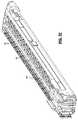
カートリッジ顎部材113は、ステープルカートリッジアセンブリ115を受容して支持する、チャネルまたはキャリア120を備える。このカートリッジアセンブリは、カートリッジ本体140および支持プレート111aを有する。このカートリッジ本体および支持プレートは、チャネルまたはキャリア120に、以下で議論されるようなスナップばめ接続、移動止め、ラッチ、または別の型の接続によって、取り付けられる。このカートリッジアセンブリは、ファスナーまたはステープル141を備える。カートリッジ本体140は、横方向に間隔を空けた複数のステープル保持スロット142を規定し、これらのステープル保持スロットは、開口部として構成される(図32を参照のこと)。各スロットは、内部にファスナーまたはステープルを受容するように構成される。カートリッジアセンブリはまた、複数のカム楔スロットを規定し、これらのカム楔スロットは、ステープルプッシャー146を収容し、そして底部で開口して、上で議論されたようなステープルの発射の際に、起動そり148がこのカートリッジアセンブリを通って長手軸方向に通過することを可能にする。
取り外し可能なステープルカートリッジアセンブリ115は、カートリッジ本体140および支持プレート111aを備える。取り外し可能なアセンブリ115は、例えば、ステープルがカートリッジ本体140から発射された後に、チャネル120から取り外し可能である。別の取り外し可能かつ交換可能なステープルカートリッジアセンブリが、このチャネルに装填されることが可能であり、その結果、装填ユニット116は、さらなるファスナーまたはステープルを再度発射するために起動され得る。 The removable
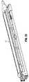
チャネル120は、ステープルカートリッジアセンブリと支持プレートとを係合させるための1つまたは1対の係合構造体120a(例えば、スロット)(図39を参照のこと)、駆動梁の通過のための中心スロット、アンビル顎部材との接続のための1対の近位穴150、および傾斜表面152を備える。近位穴150は、アンビル顎部材の対応する1対の穴または特徴と整列し/機械的に係合するように構成される。顎部材は、ピンによって接続され得、例えば、アンビル顎部材111とカートリッジ顎部材113との間の旋回関係を容易にする。
カートリッジ本体140は、中心スロット143、およびスロット143の両側に位置するステープル保持スロットの列を備える(図32を参照のこと)。カートリッジ本体はまた、1対の係合構造体または突出部を備え、これらは、特定の実施形態において、その近位端に隣接する、支持プレート111aおよび/またはチャネル120との接続のためのスロットまたは開口部であってもよい。 The
図29を特に参照すると、支持プレート111aは、基部145、カートリッジ本体および/またはチャネルとの接続のための係合特徴147および147a(図38を参照のこと)、ならびにその近位端の設置部分149(図29を参照のこと)を備える。支持プレート111aは、カートリッジ本体の下方に配置されて、ステープルプッシャー、起動そりおよびステープル(または他の外科手術用ファスナー)を支持し、そしてこれらの構成要素がステープルカートリッジアセンブリから落ちることを防止する。 With particular reference to FIG. 29, the
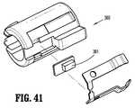
この装填ユニットは、例えば図41〜図45に示されるように、近位本体部分118の近位端に設置されたチップアセンブリ360を備え得る。このチップアセンブリは、上で議論された確証基板アセンブリ30に関して上に記載されたとおりである。チップアセンブリ360は、アダプタアセンブリ114の遠位端の連結部において基板アセンブリとの接続のために設置され、そして図1〜図21に関して上で議論されたように構成され得る。チップアセンブリ360は、確証および情報の目的のチップ361を備え、そして特定の情報を格納するメモリを備え得る。この情報は、その装填ユニットがどのような型のデバイスであるか、そのデバイス/装填ユニットのバージョン、その装填ユニットの名称、製造ロット番号、シリアルナンバーまたは他の識別番号、その装填ユニットの駆動梁が駆動され得る最大の力、インターロックゾーン(mm)、エンドゾーン(mm)、装填ユニットが関節運動し得るか否か、および/あるいは使用限度(その装填ユニットが使用され得る回数)を含み得る。このインターロックゾーンとは、駆動梁の開始位置または初期位置から測定した、この駆動梁がこの装填ユニットのロックアウトにより係合されるときの、ミリメートル単位でのこの駆動梁の位置である。このエンドゾーンとは、駆動梁の開始位置または初期位置から測定した、この駆動梁がそのステープルカートリッジ本体140内での移動の終了に達したときの、ミリメートル単位でのこの駆動梁の位置である。ステープルカートリッジアセンブリ115は、取り外されて交換され得るので、装填ユニットに新しい未発射のステープルカートリッジを再装填し得る回数に対して、意図される限度が存在する。このチップに格納される情報は、ステープル線および/またはカートリッジの長さを含み得る。 The loading unit may include a
ハンドルアセンブリ112内の制御器121aは、チップ361上の情報を読み取るようにプログラムされ得る。この情報は、外科手術用システムの操作中に使用される。望ましくは、これらの情報のうちのいくつかまたは全てが暗号化される。このことは、図1〜図21に関して上で議論されたように達成され得る。この制御器は、シリアルナンバーまたは他のデータが認識されない場合、ハンドルアセンブリ112内に配置されたモータ(図示せず)に電力を提供しないように、そしてアダプタアセンブリおよび装填ユニットを作動させないように、プログラムされ得る。最大の力の情報は、外科手術用システム内に配置された負荷センサ(例えば、ひずみゲージ)と組み合わせて使用される。例えば、負荷センサは、アダプタアセンブリ114および/または装填ユニット内に配置され得る(例えば、駆動梁上の負荷センサ)。この制御器は、この負荷センサからのデータと、このチップ上に格納された最大の力のデータとを比較するようにプログラムされ、これによって、例えば、この最大の力を超える前に、モータ(図示せず)の作動が妨害される。別の例において、この制御器は、この測定された力が予め決定されたレベルに達した場合、「低速モード」で作動するようにプログラムされ得る。この予め決定されたレベルの力は、上で議論された最大の力であり得るか、またはこのシステム内のチップ(例えば、チップ361)上に格納された、別のレベルの力であり得る。低速モードとは、制御器がモータ(図示せず)をより低い速度で作動させ、より大きいトルクを発生させ、そしてまた、組織の圧縮および/またはステープルの発射を遅くすることを意味する。厚い組織において、低速モードは、この組織内の流体がステープル留めの部位から移動することを可能にし得、この組織のより大きい圧縮を容易にし得る。 The
類似の方法で、このモータの作動は、駆動梁がインターロックゾーンまたはエンドゾーンに配置されるときに、停止され得るか、または低速モードで作動され得る。さらに、この制御器は、チップ361上のデータがその装填ユニットが関節運動しないことを示す場合、関節運動リンクのための機構、棒またはケーブルの作動を妨害または防止し得る。 In a similar manner, the operation of this motor can be stopped or operated in a low speed mode when the drive beam is located in the interlock zone or end zone. In addition, the controller may block or prevent actuation of the mechanism, rod or cable for the articulation link if the data on
上で議論されたデータのうちのいくつかまたは全てを含むチップ361が、本明細書中に開示される実施形態の任意のもの(取り外し可能かつ交換可能なステープルカートリッジアセンブリを有さない装填ユニット、および/または関節運動しない装填ユニットが挙げられる)に提供され得ることが想定される。 A
チップ361上の情報は、ハンドルアセンブリ内の制御器、このシステム内の別のチップ、またはこの外科手術用システム内の他の任意のコンピュータ構成要素によって読み取られ得ることが想定される。 It is envisioned that the information on
本明細書中に開示される実施形態の任意のものにおいて、この制御器は、この装填ユニット上のチップに情報を書き込み得る。例えば、組織をクランプするために使用された最大の力(上で議論された負荷センサによって測定されるような)、ステープルを発射するために使用された最大の力、および/または駆動梁が前進を止めるときの駆動梁の位置など。チップ361に書き込まれ得る他の情報としては、そのデバイスが低速モードに入るときの駆動梁の位置、その装填ユニットが発射された回数、その装填ユニットが発射されたか否か、ハンドルアセンブリの型、そのハンドルアセンブリのシリアルナンバー、アダプタアセンブリの型、および/またはそのアダプタアセンブリのシリアルナンバーが挙げられる。ステープルを発射するための最大の力は、本明細書中に開示される実施形態の任意のものにおいて、駆動梁の位置と一緒に保存され得る。この情報はまた、ハンドルアセンブリ内の制御器に接続されたメモリ、そのシステム内の他のチップ、またはその外科手術用システムの他のコンピュータ構成要素に保存され得る。 In any of the embodiments disclosed herein, the controller can write information to a chip on the loading unit. For example, the maximum force used to clamp tissue (as measured by the load sensors discussed above), the maximum force used to fire staples, and / or the drive beam The position of the driving beam when stopping Other information that may be written to
本明細書中に開示される実施形態の任意のものにおいて、エンドエフェクタまたはツールアセンブリは、ツールアセンブリが長手方向軸「Y−Y」と整列する第一の位置と、ツールアセンブリが長手方向軸「Y−Y」に対してある角度で配置される第二の位置との間で、関節運動するように配置されることもまた想定される。例えば、アンビル顎部材およびカートリッジ顎部材を備えるツールアセンブリは、近位本体部分118に対して旋回可能であるように設置され得る。このアンビル顎部材およびこのカートリッジ顎部材は、設置アセンブリ2020(以下でさらに議論される)に取り付けられ得、そしてこの設置アセンブリは、近位本体部分118に旋回可能に接続され得る。装填ユニット116は、近位本体部分に配置された1つまたは1つより多くのケーブルまたはリンク機構を備え、その結果、このケーブルまたはリンク機構が動くと、このツールアセンブリは、この器具に対して旋回して関節運動する。関節運動を提供することのさらなる詳細は、共有に係るMillimanらに対する米国特許第6,953,139号に詳細に記載されており、その内容はその全体が本明細書中に参考として援用される。アダプタアセンブリ114は、このツールアセンブリの関節運動を可能にするための、リンク機構、棒またはケーブルを備え得る。 In any of the embodiments disclosed herein, the end effector or tool assembly includes a first position at which the tool assembly is aligned with the longitudinal axis "Y-Y"; It is also envisioned that they are arranged to articulate between a second position located at an angle to "Y-Y". For example, a tool assembly comprising an anvil jaw member and a cartridge jaw member may be installed to be pivotable with respect to the
図32に見られるように、例えば、本明細書中に開示される実施形態の任意のものが、段状の組織接触表面1412を有するカートリッジ本体140を備え得る。このような実施形態において、異なるサイズのステープルまたは全て同じサイズのステープルが、使用され得る。複数のステープルサイズを有するステープルカートリッジのさらなる詳細は、Holstenらに対する米国特許第7,407,075号に含まれており、その全内容は、本明細書中に参考として援用される。従って、アンビルのステープル形成凹部、またはステープルプッシャー、あるいはこれらの両方は、ステープルを所望の形状およびサイズに形成するように構成され得る。 As seen in FIG. 32, for example, any of the embodiments disclosed herein can include a
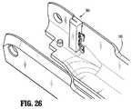
取り外し可能かつ交換可能なステープルカートリッジアセンブリ115は、チップアセンブリ362をさらに備え得る(図27および図28を参照のこと)。対応する基板アセンブリ380(図25および図26)が、装填ユニット116のツールアセンブリ上に配置され、そしてチャネル120上に配置され得る。このツールアセンブリの基板アセンブリ380は、アダプタ連結部27のアダプタ基板アセンブリ50に関して上で議論されたように構成され得る。このツールアセンブリの基板アセンブリ380は、チャネル120の壁に固定されて設置されるように構成される。この基板アセンブリ380は、カートリッジアセンブリ140が装填ユニットのチャネル120に固定されるときに、チップアセンブリ362がこのチャネルに設置された基板アセンブリ380に係合するように、配置される(図29〜図31を参照のこと)。図27および図28は、チップアセンブリとステープルカートリッジ本体140との間の関係を示し、一方で、図29は、チップアセンブリ362と支持プレート111aとの間の関係を示す。 The removable and replaceable
より詳細には、チップアセンブリは、本体337、ならびにこの本体に配置されたチップ336に接続された1対の接触子部材340a、340b(まとめて、接触子部材340)を備える。本体337は、可撓性アームを有する矩形の部材を規定し、これらの可撓性アーム上には、スナップ特徴337aがある。これらの可撓性アームは、カートリッジ本体に規定された凹部331に固定されて受容されるように構成される。チップ336は、接触子部材340と電気通信する。 More specifically, the tip assembly includes a
チップ336は、ステープルカートリッジアセンブリ115に関する情報を格納することが可能な、任意のチップを備える。このチップは、確証基板アセンブリ30のチップと同じであっても類似であってもよい。本明細書中に開示される実施形態の任意のものにおいて、これらのチップの任意のものが、情報(例えば、限定されないが、カートリッジサイズ、ステープル配置、ステープル線の長さ(またはカートリッジの長さ)、製造日、使用期限、互換性特徴、独特の識別子(例えば、シリアルナンバー)、および/または使用回数、ならびにこのステープルカートリッジアセンブリが使用されたことがあるか否か)を格納し得る。このような情報は、ハンドルアセンブリ112内の制御器、または別のコンピュータ構成要素に、適切なバス、ピン接続、無線手段などを介して伝送され得る。いくつかの実施形態において、チップ336は、消去可能再書込み可能読出し専用メモリ(「EPROM」)チップを備える。このハンドルアセンブリ内の制御器は、チップ336に情報を書き込み得る。この方法で、ハンドルアセンブリ112は、チップ336から伝送される、ステープルカートリッジアセンブリに関する情報に従って、このハンドルアセンブリの発射力、発射行程、および/または他の作動特徴を調節し得る。ハンドルアセンブリ112は、チップ336に、このステープルカートリッジアセンブリが使用されたことがあることを通信し得、これにより、使い果たされたリロードアセンブリの再装填もしくは再使用、または他の任意の認可されない使用を防止し得る。この外科手術用システム内の構成要素のいずれかに格納された情報は、秘密鍵、公開鍵、および/またはセキュアハッシュアルゴリズムを使用して、暗号化され得る。 Tip 336 comprises any tip capable of storing information about
基板アセンブリ380はまた、1対の接触子380aおよび380b、ならびに本体381を有する。この基板アセンブリは、ステープルカートリッジアセンブリがチャネル120内に適切に設置されるときに、チップアセンブリ362と接触するために設置される。接触子380a、380b、340a、および340bは、図に見られるようなL字形の構成を有し、その結果、これらの接触子は、互いに弾力的に係合し得る。本体381は、スナップ特徴382を規定し得、このスナップ特徴は、この基板アセンブリを固定して設置するために、チャネル内の穴383に係合するために提供される。この基板アセンブリは、チップアセンブリ362からハンドルアセンブリ内の制御器へ、または他の任意のコンピュータデバイスへの情報の伝送のために、バスもしくはワイヤに適切に接続されるか、または無線通信手段を有する。 The
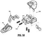
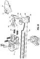
本明細書中に開示される実施形態の任意のものにおいて、ロックアウト機構500が、装填ユニット内に配置される。この装填ユニットは、上で議論されたように構成され得る。さらに、本開示は、ロックアウトを有する取り外し可能なアセンブリ、またはロックアウトを有する装填ユニットに関する。 In any of the embodiments disclosed herein, a lockout mechanism 500 is located within the loading unit. This loading unit may be configured as discussed above. Further, the present disclosure relates to a removable assembly having a lockout, or a loading unit having a lockout.
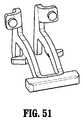
ロックアウト機構500は、ラッチ2010および少なくとも1つのばね2030を備え、そしてステープルカートリッジアセンブリ115またはステープルカートリッジ26の再発射を防止するように、そしてまた、ステープルカートリッジが発射された後であって別のカートリッジアセンブリ115の装填前の駆動梁の遠位方向への並進を防止するように、構成される。ロックアウト機構500は、図50において、そり148および設置アセンブリ2020と並んで図示されている。少なくとも1つのばね2030は、遠位に面する表面2031に設置される。例えば、表面2031に、ばね2030を受容するための凹部が形成される。対応するポストが、ラッチ2010の近位に面する表面に提供される。このラッチは、装填ユニット内で旋回可能であるように構成され、そして少なくとも1つのプロング2012、後方部分2014、および支持部分2016を備える。このラッチは、図50および図51において下方に垂れ下がる2つの特徴として示される支持部分2016の周りで旋回するように構成され、そしてばね2030(単数または複数)によって付勢される。そり148は、ラッチおよび駆動梁が初期位置にあるときに少なくとも1つのプロング2012を受容するための、穴または凹部を有する(図52を参照のこと)。駆動梁2039は、上フランジ2042、下フランジ2044、およびナイフ刃2046を有する動的クランピング部材2040(図53を参照のこと)と相互作用し得るか、またはこの動的クランピング部材2040を備え得る。 Lockout mechanism 500 includes a
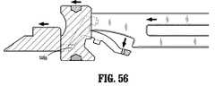
この初期位置において、ラッチ2010は、前方または遠位方向に付勢され、このとき後方部分2014は、駆動梁2039の縁部2039aと接触して、このラッチのさらなる回転運動を防止する。この駆動梁およびこの動的クランピング部材が前方または遠位方向に移動するにつれて、この動的クランピング部材は、このそりを遠位方向に押す。このそりの後方部分148aは、プロング2012(単数または複数)を押し、このラッチを、少なくとも1つのばね2030の付勢に逆らって傾斜させる。これによって、後方部分2014が縁部2039aの近くの領域から外され、そして駆動梁および動的クランピング部材が前方に移動することを可能にする。この動的クランピング部材がラッチ2010を通過した後に、このラッチは、このばねの影響下で前方に回転する(図57を参照のこと)。 In this initial position, the
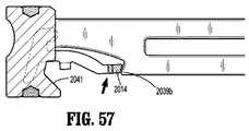
動的クランピング部材およびそりがステープルをカートリッジ140から発射した後に、この動的クランピング部材は近位方向に移動し、このそりをカートリッジ140およびカートリッジアセンブリ115の遠位端に残す。カム表面2041がラッチを移動路から離れるように動かすと、この動的クランピング部材は、ラッチ2010を超えて移動し得る(図57を参照のこと)。一旦、この動的クランピング部材がその初期位置に戻ると、ラッチ2010は、動的クランピング部材2040のさらに前方への移動を防止する。このラッチの後方部分2014は、この駆動梁の別の縁部2039bに係合するように位置する(図57を参照のこと)。この装填ユニットが、取り外し可能かつ交換可能なステープルカートリッジアセンブリ115を受け入れる型のものである場合、カートリッジアセンブリ115は、ラッチ2010をその初期位置に戻すように構成され得、その結果、この駆動梁およびこの動的クランピング部材は、再度遠位方向に移動させられて、別のセットのステープルを発射させ得る。 After the dynamic clamping member and sled fire staples from
上で議論されたように、本明細書中に開示される実施形態の任意のものは、装填ユニット116などの外科手術用ステープル留め装填ユニット上に、上で議論されたロックアウト機構などのロックアウト機構に関する情報を有するチップアセンブリ360を備え得る。さらに、このロックアウト機構に関する情報が、チップ361上に格納され得る。例えば、そのロックアウト機構が係合されたという事実が、ハンドル内の制御器によって、チップアセンブリ360および/またはチップアセンブリ362に記録され得る。このハンドル内の制御器は、情報を格納するためのメモリ(プロセッサ、および他のコンピュータ構成要素が挙げられる)を備え得る。この制御器はまた、このハンドルアセンブリのモータの電流を測定するための電流計、すなわちアンメータを備え得る。この制御器は、この装填ユニットおよび/またはステープルカートリッジアセンブリの使用中に達したピーク電流を記録するようにプログラムされ得、そしてこのピーク電流を、このシステム内のチップまたは他のコンピュータ構成要素のうちの任意のものに記録し得る。ステープルが発射された後に達するピーク電流は、新しいステープルカートリッジアセンブリがその装填ユニットに設置される前に、この装填ユニットを再び発射させることを試みられたことの指標であり得る。あるいは、このロックアウト機構は、センサを、例えばラッチ上に備え得る。この外科手術用システムは、上で議論されたものと同様の、ロックアウト機構を有さない装填ユニットを備え得ることが想定される。その装填ユニットがロックアウト機構を有さないという事実は、チップ361に格納され得る。 As discussed above, any of the embodiments disclosed herein may include a lock on a surgical stapling loading unit, such as
このハンドルアセンブリはまた、モータ出力シャフトの回転が何回行われたかを決定するエンコーダを備え得、これは、アダプタアセンブリ内の駆動棒、リンク機構、ケーブルなど、装填ユニット内の駆動梁もしくは発射棒、または他の構成要素の位置を決定するために使用され得る。あるいは、他のセンサが、その外科手術用システム内の種々の構成要素の位置を決定するために、使用され得る。 The handle assembly may also include an encoder that determines how many rotations of the motor output shaft have occurred, such as a drive rod, linkage, cable, etc. in the adapter assembly, a drive beam or firing rod in the loading unit. , Or other components. Alternatively, other sensors may be used to determine the position of various components within the surgical system.
本明細書中に開示されるアダプタアセンブリは、本明細書中に開示される実施形態の任意のものにおいて、米国特許出願公開第2011/0174099 A1号に開示されるように構成され得、その全開示は、本明細書中に参考として援用される。ハンドルアセンブリ内のモータは、回転出力を回転シャフトに提供し、そしてアダプタは、この出力を、直線運動するリンク機構または棒に転換するように構成され、そしてまた、装填ユニット116の近位本体部分118内の関節運動リンク機構に駆動を提供し得る。ハンドルアセンブリおよび/またはアダプタアセンブリは、米国特許出願公開第2014/0012289 A1号および同第2014/0110453 A1号に開示されるように構成され得、これらの全開示は、本明細書中に参考として援用される。 The adapter assembly disclosed herein may be configured in any of the embodiments disclosed herein as disclosed in U.S. Patent Application Publication No. 2011/0174099 A1, wherein The disclosure is incorporated herein by reference. The motor in the handle assembly provides a rotational output to the rotating shaft, and the adapter is configured to convert this output to a linearly moving linkage or rod, and also to the proximal body portion of the
力測定および駆動回路
本明細書中に開示される実施形態の任意のものは、力測定および駆動回路を備え得るか、または力測定および駆動回路を有する構成要素と一緒に使用されるように構成され得る。モータ駆動機構によってエンドエフェクタアセンブリに加えられる力がモータ電流測定によって推定される、ファスナーを付けるための外科手術用器具は、公知である。しかし、温度によって変わる、この測定スキームにおいては、エラーの元が存在し得、そしてある組み合わせのエンドエフェクタアセンブリおよびアダプタと、別の組み合わせのエンドエフェクタアセンブリおよびアダプタとの間の摩擦の差に起因する不確実性が存在し、このことは、モータ電流のみによって推定される力は、その信頼性が変わりやすいことを意味する。Force Measurement and Drive Circuit Any of the embodiments disclosed herein may comprise a force measurement and drive circuit or may be configured for use with components having a force measurement and drive circuit Can be done. Surgical instruments for fastening are known in which the force applied to the end effector assembly by a motor drive is estimated by motor current measurements. However, in this measurement scheme, which varies with temperature, there may be sources of error and due to the difference in friction between one set of end effector assemblies and adapters and another set of end effector assemblies and adapters. There is uncertainty, which means that the force estimated by the motor current alone is variable in its reliability.
本開示の種々の実施形態は、エンドエフェクタアセンブリをモータ駆動機構に作動可能に接続するように構成され、そしてアダプタ内の駆動力を直接測定するように構成された、アダプタを備える外科手術用器具を提供する。本開示の外科手術用器具の実施形態は、過剰な負荷を検出すること、ならびに/あるいはアダプタおよび/またはハンドルアセンブリへの損傷を防止することが可能であり、これにより、信頼性が増大し得る。本開示の外科手術用器具の種々の実施形態はまた、組織圧縮に関するデータを収集することが可能である。本開示の外科手術用器具の実施形態は、組織端部停止(end stop)または端部停止条件にいつ達したかを正確に決定するように構成される。 Various embodiments of the present disclosure provide a surgical instrument with an adapter configured to operatively connect an end effector assembly to a motor drive mechanism and configured to directly measure a driving force in the adapter. I will provide a. Embodiments of the surgical instrument of the present disclosure can detect overload and / or prevent damage to the adapter and / or handle assembly, which may increase reliability. . Various embodiments of the presently disclosed surgical instrument are also capable of collecting data regarding tissue compression. Embodiments of the surgical instrument of the present disclosure are configured to accurately determine when a tissue end stop or end stop condition has been reached.
本開示の外科手術用器具の種々の実施形態は、ひずみゲージおよび駆動回路を用いて構成されたアダプタを利用する。以下の説明は、ひずみゲージの使用を記載するが、本開示の教示はまた、加えられる圧力に比例する電気出力を提供することが可能な種々の感知デバイスに応用され得る。いくつかの実施形態において、この駆動回路は、専用計測増幅器、カスタム同調2極フィルタ、低電力モードスイッチ、12ビットアナログデジタル変換器、および32ビットマイクロプロセッサを備える。以下の説明は、外科手術用ステープルを付けるための外科手術用器具の使用を記載するが、本開示の教示はまた、エンドエフェクタアセンブリおよびシャフトを備える種々の外科手術用デバイス(例えば、組織を封止するデバイス)に応用され得る。 Various embodiments of the surgical instrument of the present disclosure utilize an adapter configured with a strain gauge and a drive circuit. Although the following description describes the use of strain gauges, the teachings of the present disclosure can also be applied to various sensing devices that can provide an electrical output proportional to the applied pressure. In some embodiments, the drive circuit includes a dedicated instrumentation amplifier, a custom tuned two-pole filter, a low power mode switch, a 12-bit analog-to-digital converter, and a 32-bit microprocessor. Although the following description describes the use of a surgical instrument to apply surgical staples, the teachings of the present disclosure also provide for various surgical devices (e.g., tissue sealing) with an end effector assembly and a shaft. Stopping device).
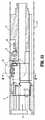
図58は、種々の外科手術手順(例えば、内視鏡外科手術手順)において使用するための外科手術用器具1110を図示し、この外科手術用器具は、モータパック1150、バッテリパック1160、アダプタ1120、および交換可能な装填ユニット1114(ステープルを付けるように構成されたエンドエフェクタアセンブリ1111を有する)を備える。交換可能な装填ユニット1114および/またはエンドエフェクタアセンブリ1111は、種々のサイズのステープルを備え得、そしてこれらのステープルは、1つまたは1つより多くの構成で配置され得る。いくつかの実施形態において、交換可能な装填ユニット1114は、アダプタ1120の遠位端に解放可能に連結されるように構成される。 FIG. 58 illustrates a
図58に図示されるように、外科手術用器具1110は、モータパック1150およびバッテリパック1160を保持するように構成されたクラムシェル1140を備え、そしてクラムシェル1140を介してアダプタ1120をモータパック1150に作動可能に連結するための連結機構1130を備える。外科手術用器具1110はさらに、または代替的に、ハンドルアセンブリ(図示せず)を備え得、この場合、アダプタ1120は、このハンドルアセンブリの遠位端から延びる。いくつかの実施形態において、器具1110は、器具1110を外部電源に接続するための伝送線(図示せず)を備え得る。 As shown in FIG. 58, the
本開示の実施形態によれば、駆動力は、アダプタ1120において、ひずみゲージ1122または他の力センサ、およびこれと作動可能に関連する駆動回路1129を使用して、直接測定される。本開示の外科手術用器具1110の実施形態は、工場較正力測定値を含み得、これによって、傾き補正因子およびオフセット補正因子が、駆動回路1129のマイクロプロセッサ(例えば、図59および図60に示されるマイクロプロセッサ1240)に永続的に格納される。この方法で、アダプタ1120は、異なるハンドルアセンブリ、またはクラムシェル1140間で交換され得、そして較正された力測定値が保証される。いくつかの実施形態において、行程の終了時に較正された力測定値は上昇し、このことは、信頼性のある端部停止検出を可能にすることを補助する。 According to embodiments of the present disclosure, the driving force is measured directly at the
力センサおよび力変換器は、温度によって、および経時的に、オフセットのドリフトを示し得る。本開示の実施形態によれば、力変換器は、製造中に工場で較正される。この較正は、補正因子をマイクロプロセッサ(例えば、図59および図60に示されるマイクロプロセッサ1240)に提供する。この補正因子は、変換器(例えば、ひずみゲージ1122)から受信されたデータを修正して、工場での製造中に加えられる現実の力と一致させるために、このマイクロプロセッサによって使用されるためのものである。図示される実施形態において、この較正は最初に、変換器オフセット「Y1」の測定を伴う。次に、既知の力「F1」がこの変換器に加えられ、そしてこの変換器の出力が測定されて、データ点「Y2」を与える。見かけの傾き「Sapp」が、等式Sapp=(Y2−Y1)/F1を使用して計算され得る。 Force sensors and transducers may exhibit offset drift with temperature and over time. According to embodiments of the present disclosure, the force transducer is factory calibrated during manufacturing. This calibration provides a correction factor to the microprocessor (eg,
オフセット「Y1」は、マイクロプロセッサ1240に格納され得(そして/またはこれと作動可能に関連するメモリに格納され得)、そしてマイクロプロセッサ1240は、変換器から受信された全てのデータから、オフセット「Y1」を減算するように構成され得る。これは、y=mx+bの等式を使用してこの変換器から予測される直線に対する、「b」補正に相当する。この傾きの補正は、最初に「Sapp」を理想値「Si」(これは、力「F1」が入力される場合のこのシステムの理想出力である)と比較することによって、計算され得る。y=mx+bの等式の項「m」は、比Si/Sappによって修正される。 Offset "Y1" may be stored in microprocessor 1240 (and / or may be stored in memory operatively associated therewith), and
図59および図60において、駆動回路1129(図58)の回路図が示されており、この回路図は、計測増幅器1220、マイクロプロセッサ1240、演算増幅器すなわち「オペアンプ」1230、およびひずみゲージ1122に接続されたインターフェース1215、ならびにオン/オフ能力を提供する電源オン/オフ回路1210を含む。図60に示されるように、駆動回路1129は、電圧調整回路1250をさらに備え、これは、クリーンなDC電圧を提供する。いくつかの実施形態において、電圧調整回路1250は、3.3ボルトのDC電圧を提供する。 59 and 60, circuit diagrams of drive circuit 1129 (FIG. 58) are shown, which are connected to
計測増幅器1220は、電力供給源注入比、および電流消費がないことのために選択される。計測増幅器1220は、比較的ノイズが多い信号、またはひずみゲージからの非常に弱い信号を増大させるように設計される。例えば、この信号を約50倍増大させる。オペアンプ1230は一般に、低い電流消費および小さいサイズを有し、そして増幅器1220からの信号を約10倍増大させるように構成され得る。いくつかの実施形態において、オペアンプ1230は、20Hzのカットオフ周波数で20dBの増加を提供し、そして二極バターワースフィルタであり得る。オペアンプ1230はまた、低域フィルタリングを提供して、例えば、モータのノイズを排除し得、そして/または電磁気干渉(EMI)抑制を提供し得る。オペアンプ1230のアナログ出力は、導体1231を介してマイクロプロセッサ1240のアナログ−デジタル入力に伝送され、そしてデジタル形式に変換される。駆動回路1129をアダプタ1120内に収容するための空間の制約に起因して、オペアンプ1230およびマイクロプロセッサ1240を選択する際の主要な懸念事項のうちの1つは、サイズが小さいことである。
本明細書中以下で、本開示による外科手術用デバイスにおける駆動力を測定する方法が、図61を参照しながら記載される。本明細書中に提供される方法の工程は、本開示の範囲から逸脱することなく、組み合わせて、そして本明細書中に提供される順序とは異なる順序で、実施され得ることが理解されるべきである。 Hereinafter, a method for measuring driving force in a surgical device according to the present disclosure will be described with reference to FIG. It is understood that the method steps provided herein can be performed in combination and in a different order than the ones provided herein without departing from the scope of the present disclosure. Should.
図61は、本開示の1つの実施形態による、外科手術用デバイスにおける駆動力を測定する方法を図示する流れ図である。工程1410において、外科手術用器具1110が提供され、この外科手術用器具は、エンドエフェクタアセンブリ1111を有する交換可能な装填ユニット1114を駆動モータ1150に解放可能に連結するように構成されたアダプタ1120を備える。アダプタ1120は、過剰な負荷を検出することが可能な、駆動回路1129に連結されたひずみゲージ1122を備える。いくつかの実施形態において、このエンドエフェクタアセンブリは、ステープルを付けるように構成される。 FIG. 61 is a flowchart illustrating a method of measuring driving force in a surgical device according to one embodiment of the present disclosure. At
いくつかの実施形態において、駆動回路1129は、マイクロプロセッサ1240およびオペアンプ1230を備える。オペアンプ1230は、低域フィルタリングを提供するように構成され得、そして/または二極バターワースフィルタであり得る。いくつかの実施形態において、図61に図示される方法は、オペアンプ1230のアナログ出力をマイクロプロセッサ1240のアナログ−デジタル入力に伝送する工程をさらに包含し得る。駆動回路1129は、電圧調整回路1250をさらに備え得、これは3.3ボルトのDC電圧を提供し得る。 In some embodiments, the
工程1420において、ひずみゲージ1122および駆動回路1129を使用して、アダプタ1120における駆動力を直接測定し、力測定値を得る。 At
工程1430において、この力測定値に基づいて、過剰な負荷が検出されたことが決定される場合、アダプタ1120に対する損傷を防止するように、この駆動力が調節される。 If it is determined in
いくつかの実施形態において、図61に図示される方法は、エンドエフェクタアセンブリを使用してステープルを付ける工程、および/または内視鏡外科手術手順においてエンドエフェクタアセンブリ1111を利用する工程をさらに包含し得る。 In some embodiments, the method illustrated in FIG. 61 further comprises applying staples using an end effector assembly and / or utilizing the
上記外科手術用器具、および外科手術用デバイスにおける駆動力を測定する方法は、内視鏡外科手術手順における利用に適切であり得、そして/または直視下外科手術用途における利用に適切であり得る。 The surgical instruments and methods of measuring driving force in a surgical device may be suitable for use in endoscopic surgical procedures and / or may be suitable for use in open surgical applications.
図1〜図57に関して記載された実施形態の任意のものが、上で議論されたひずみゲージ(もしくは他の力センサ)および/または駆動回路を備え得る。本明細書中に開示される実施形態の任意のものにおいて、ハンドルアセンブリまたはクラムシェル内のモータは、1つまたは1つより多くのドライブ(例えば、回転可能なドライブコネクタ)を起動させるように構成された、任意の電気モータであり得る。このモータは、バッテリに連結され、このバッテリは、DCバッテリ(例えば、充電式の鉛ベースのバッテリ、ニッケルベースのバッテリ、リチウムイオンベースのバッテリなど)、AC/DC変圧器、またはこのモータに電気エネルギーを提供するために適した他の電源であり得る。 Any of the embodiments described with respect to FIGS. 1-57 may include a strain gauge (or other force sensor) and / or drive circuitry as discussed above. In any of the embodiments disclosed herein, the motor in the handle assembly or clamshell is configured to activate one or more drives (eg, rotatable drive connectors). It can be any electric motor created. The motor is coupled to a battery, which can be a DC battery (eg, a rechargeable lead-based battery, a nickel-based battery, a lithium-ion-based battery, etc.), an AC / DC transformer, or an electric power source for the motor. It can be any other power source suitable for providing energy.
図示および説明の目的で、添付の図面を参照しながら実施形態が詳細に記載されたが、開示されるプロセスおよび装置は、それらによって限定されると解釈されるべきではないことが理解されるべきである。例えば、ひずみゲージまたは他の力センサは、駆動梁、動的クランピング部材、アンビル、またはこの外科手術用システムにおける他の構成要素に提供され得る。上記実施形態に対する種々の改変が、本開示の範囲から逸脱することなくなされ得ることが、当業者に明らかである。 While the embodiments have been described in detail for purposes of illustration and description with reference to the accompanying drawings, it should be understood that the disclosed processes and apparatus should not be construed as limited thereby. It is. For example, a strain gauge or other force sensor may be provided on the drive beam, dynamic clamping member, anvil, or other components in the surgical system. It will be apparent to those skilled in the art that various modifications to the above embodiments can be made without departing from the scope of the present disclosure.
Claims (10)
Translated fromJapaneseハンドルアセンブリと、
前記ハンドルアセンブリ内に配置された駆動モータと、
エンドエフェクタアセンブリを有する交換可能な装填ユニットと、
前記ハンドルアセンブリに解放可能に結合するように構成され、かつ、前記交換可能な装填ユニットに解放可能に結合するように構成されたアダプタであって、その結果、前記交換可能な装填ユニットが前記駆動モータに結合され、前記アダプタは、ひずみゲージと、前記ひずみゲージに直接結合された駆動回路とを含み、前記駆動回路は、前記アダプタ内にマイクロプロセッサを含み、前記ひずみゲージと前記駆動回路とは、前記アダプタにおける駆動力を直接測定するように構成されている、アダプタと
を備える、外科手術用器具。A surgical instrument for attaching a fastener, wherein the surgical instrument comprises:
A handle assembly;
A drive motor disposed within the handle assembly;
A replaceable loading unit having an end effector assembly;
An adapter configured to releasably couple to the handle assembly and to releasably couple to the replaceable loading unit, such that the replaceable loading unit is driven by the drive unit. Coupled to a motor, the adapter includes a strain gauge and a drive circuit directly coupled to the strain gauge, the drive circuit including a microprocessor in the adapter, the strain gauge and the drive circuit A surgical instrument comprising: an adapter configured to directly measure a driving force at the adapter.
Applications Claiming Priority (4)
| Application Number | Priority Date | Filing Date | Title |
|---|---|---|---|
| US201461988342P | 2014-05-05 | 2014-05-05 | |
| US61/988,342 | 2014-05-05 | ||
| US14/670,781US10175127B2 (en) | 2014-05-05 | 2015-03-27 | End-effector force measurement drive circuit |
| US14/670,781 | 2015-03-27 |
Related Child Applications (1)
| Application Number | Title | Priority Date | Filing Date |
|---|---|---|---|
| JP2019032605ADivisionJP7022087B2 (en) | 2014-05-05 | 2019-02-26 | End effector force measurement drive circuit |
Publications (2)
| Publication Number | Publication Date |
|---|---|
| JP2015211832A JP2015211832A (en) | 2015-11-26 |
| JP6671859B2true JP6671859B2 (en) | 2020-03-25 |
Family
ID=53015731
Family Applications (3)
| Application Number | Title | Priority Date | Filing Date |
|---|---|---|---|
| JP2015088456AActiveJP6671859B2 (en) | 2014-05-05 | 2015-04-23 | End effector force measurement drive circuit |
| JP2019032605AActiveJP7022087B2 (en) | 2014-05-05 | 2019-02-26 | End effector force measurement drive circuit |
| JP2021055230AWithdrawnJP2021100640A (en) | 2014-05-05 | 2021-03-29 | End-effector force measurement drive circuit |
Family Applications After (2)
| Application Number | Title | Priority Date | Filing Date |
|---|---|---|---|
| JP2019032605AActiveJP7022087B2 (en) | 2014-05-05 | 2019-02-26 | End effector force measurement drive circuit |
| JP2021055230AWithdrawnJP2021100640A (en) | 2014-05-05 | 2021-03-29 | End-effector force measurement drive circuit |
Country Status (7)
| Country | Link |
|---|---|
| US (2) | US10175127B2 (en) |
| EP (1) | EP2942028B1 (en) |
| JP (3) | JP6671859B2 (en) |
| CN (1) | CN105078530B (en) |
| AU (1) | AU2015201756B2 (en) |
| CA (1) | CA2887955C (en) |
| ES (1) | ES2867073T3 (en) |
Families Citing this family (710)
| Publication number | Priority date | Publication date | Assignee | Title |
|---|---|---|---|---|
| US9060770B2 (en) | 2003-05-20 | 2015-06-23 | Ethicon Endo-Surgery, Inc. | Robotically-driven surgical instrument with E-beam driver |
| US20070084897A1 (en) | 2003-05-20 | 2007-04-19 | Shelton Frederick E Iv | Articulating surgical stapling instrument incorporating a two-piece e-beam firing mechanism |
| US8215531B2 (en) | 2004-07-28 | 2012-07-10 | Ethicon Endo-Surgery, Inc. | Surgical stapling instrument having a medical substance dispenser |
| US9072535B2 (en) | 2011-05-27 | 2015-07-07 | Ethicon Endo-Surgery, Inc. | Surgical stapling instruments with rotatable staple deployment arrangements |
| US11998198B2 (en) | 2004-07-28 | 2024-06-04 | Cilag Gmbh International | Surgical stapling instrument incorporating a two-piece E-beam firing mechanism |
| US11890012B2 (en) | 2004-07-28 | 2024-02-06 | Cilag Gmbh International | Staple cartridge comprising cartridge body and attached support |
| US7934630B2 (en) | 2005-08-31 | 2011-05-03 | Ethicon Endo-Surgery, Inc. | Staple cartridges for forming staples having differing formed staple heights |
| US7669746B2 (en) | 2005-08-31 | 2010-03-02 | Ethicon Endo-Surgery, Inc. | Staple cartridges for forming staples having differing formed staple heights |
| US9237891B2 (en) | 2005-08-31 | 2016-01-19 | Ethicon Endo-Surgery, Inc. | Robotically-controlled surgical stapling devices that produce formed staples having different lengths |
| US10159482B2 (en) | 2005-08-31 | 2018-12-25 | Ethicon Llc | Fastener cartridge assembly comprising a fixed anvil and different staple heights |
| US11246590B2 (en) | 2005-08-31 | 2022-02-15 | Cilag Gmbh International | Staple cartridge including staple drivers having different unfired heights |
| US11484312B2 (en) | 2005-08-31 | 2022-11-01 | Cilag Gmbh International | Staple cartridge comprising a staple driver arrangement |
| US20070106317A1 (en) | 2005-11-09 | 2007-05-10 | Shelton Frederick E Iv | Hydraulically and electrically actuated articulation joints for surgical instruments |
| US20120292367A1 (en) | 2006-01-31 | 2012-11-22 | Ethicon Endo-Surgery, Inc. | Robotically-controlled end effector |
| US7753904B2 (en) | 2006-01-31 | 2010-07-13 | Ethicon Endo-Surgery, Inc. | Endoscopic surgical instrument with a handle that can articulate with respect to the shaft |
| US20110024477A1 (en) | 2009-02-06 | 2011-02-03 | Hall Steven G | Driven Surgical Stapler Improvements |
| US8820603B2 (en) | 2006-01-31 | 2014-09-02 | Ethicon Endo-Surgery, Inc. | Accessing data stored in a memory of a surgical instrument |
| US8708213B2 (en) | 2006-01-31 | 2014-04-29 | Ethicon Endo-Surgery, Inc. | Surgical instrument having a feedback system |
| US11793518B2 (en) | 2006-01-31 | 2023-10-24 | Cilag Gmbh International | Powered surgical instruments with firing system lockout arrangements |
| US11278279B2 (en) | 2006-01-31 | 2022-03-22 | Cilag Gmbh International | Surgical instrument assembly |
| US11224427B2 (en) | 2006-01-31 | 2022-01-18 | Cilag Gmbh International | Surgical stapling system including a console and retraction assembly |
| US7845537B2 (en) | 2006-01-31 | 2010-12-07 | Ethicon Endo-Surgery, Inc. | Surgical instrument having recording capabilities |
| US8186555B2 (en) | 2006-01-31 | 2012-05-29 | Ethicon Endo-Surgery, Inc. | Motor-driven surgical cutting and fastening instrument with mechanical closure system |
| US20110295295A1 (en) | 2006-01-31 | 2011-12-01 | Ethicon Endo-Surgery, Inc. | Robotically-controlled surgical instrument having recording capabilities |
| US8992422B2 (en) | 2006-03-23 | 2015-03-31 | Ethicon Endo-Surgery, Inc. | Robotically-controlled endoscopic accessory channel |
| US8322455B2 (en) | 2006-06-27 | 2012-12-04 | Ethicon Endo-Surgery, Inc. | Manually driven surgical cutting and fastening instrument |
| US7506791B2 (en) | 2006-09-29 | 2009-03-24 | Ethicon Endo-Surgery, Inc. | Surgical stapling instrument with mechanical mechanism for limiting maximum tissue compression |
| US10568652B2 (en) | 2006-09-29 | 2020-02-25 | Ethicon Llc | Surgical staples having attached drivers of different heights and stapling instruments for deploying the same |
| US11980366B2 (en) | 2006-10-03 | 2024-05-14 | Cilag Gmbh International | Surgical instrument |
| US11291441B2 (en) | 2007-01-10 | 2022-04-05 | Cilag Gmbh International | Surgical instrument with wireless communication between control unit and remote sensor |
| US8632535B2 (en) | 2007-01-10 | 2014-01-21 | Ethicon Endo-Surgery, Inc. | Interlock and surgical instrument including same |
| US8652120B2 (en) | 2007-01-10 | 2014-02-18 | Ethicon Endo-Surgery, Inc. | Surgical instrument with wireless communication between control unit and sensor transponders |
| US8684253B2 (en) | 2007-01-10 | 2014-04-01 | Ethicon Endo-Surgery, Inc. | Surgical instrument with wireless communication between a control unit of a robotic system and remote sensor |
| US11039836B2 (en) | 2007-01-11 | 2021-06-22 | Cilag Gmbh International | Staple cartridge for use with a surgical stapling instrument |
| US20080169333A1 (en) | 2007-01-11 | 2008-07-17 | Shelton Frederick E | Surgical stapler end effector with tapered distal end |
| US7673782B2 (en) | 2007-03-15 | 2010-03-09 | Ethicon Endo-Surgery, Inc. | Surgical stapling instrument having a releasable buttress material |
| US8893946B2 (en) | 2007-03-28 | 2014-11-25 | Ethicon Endo-Surgery, Inc. | Laparoscopic tissue thickness and clamp load measuring devices |
| US11564682B2 (en) | 2007-06-04 | 2023-01-31 | Cilag Gmbh International | Surgical stapler device |
| US8931682B2 (en) | 2007-06-04 | 2015-01-13 | Ethicon Endo-Surgery, Inc. | Robotically-controlled shaft based rotary drive systems for surgical instruments |
| US7753245B2 (en) | 2007-06-22 | 2010-07-13 | Ethicon Endo-Surgery, Inc. | Surgical stapling instruments |
| US11849941B2 (en) | 2007-06-29 | 2023-12-26 | Cilag Gmbh International | Staple cartridge having staple cavities extending at a transverse angle relative to a longitudinal cartridge axis |
| US11986183B2 (en) | 2008-02-14 | 2024-05-21 | Cilag Gmbh International | Surgical cutting and fastening instrument comprising a plurality of sensors to measure an electrical parameter |
| US8636736B2 (en) | 2008-02-14 | 2014-01-28 | Ethicon Endo-Surgery, Inc. | Motorized surgical cutting and fastening instrument |
| US9179912B2 (en) | 2008-02-14 | 2015-11-10 | Ethicon Endo-Surgery, Inc. | Robotically-controlled motorized surgical cutting and fastening instrument |
| US7819298B2 (en) | 2008-02-14 | 2010-10-26 | Ethicon Endo-Surgery, Inc. | Surgical stapling apparatus with control features operable with one hand |
| US8573465B2 (en) | 2008-02-14 | 2013-11-05 | Ethicon Endo-Surgery, Inc. | Robotically-controlled surgical end effector system with rotary actuated closure systems |
| US8758391B2 (en) | 2008-02-14 | 2014-06-24 | Ethicon Endo-Surgery, Inc. | Interchangeable tools for surgical instruments |
| US7866527B2 (en) | 2008-02-14 | 2011-01-11 | Ethicon Endo-Surgery, Inc. | Surgical stapling apparatus with interlockable firing system |
| JP5410110B2 (en) | 2008-02-14 | 2014-02-05 | エシコン・エンド−サージェリィ・インコーポレイテッド | Surgical cutting / fixing instrument with RF electrode |
| US9585657B2 (en) | 2008-02-15 | 2017-03-07 | Ethicon Endo-Surgery, Llc | Actuator for releasing a layer of material from a surgical end effector |
| US9005230B2 (en) | 2008-09-23 | 2015-04-14 | Ethicon Endo-Surgery, Inc. | Motorized surgical instrument |
| US11648005B2 (en) | 2008-09-23 | 2023-05-16 | Cilag Gmbh International | Robotically-controlled motorized surgical instrument with an end effector |
| US8210411B2 (en) | 2008-09-23 | 2012-07-03 | Ethicon Endo-Surgery, Inc. | Motor-driven surgical cutting instrument |
| US9386983B2 (en) | 2008-09-23 | 2016-07-12 | Ethicon Endo-Surgery, Llc | Robotically-controlled motorized surgical instrument |
| US8608045B2 (en) | 2008-10-10 | 2013-12-17 | Ethicon Endo-Sugery, Inc. | Powered surgical cutting and stapling apparatus with manually retractable firing system |
| US8517239B2 (en) | 2009-02-05 | 2013-08-27 | Ethicon Endo-Surgery, Inc. | Surgical stapling instrument comprising a magnetic element driver |
| US8444036B2 (en) | 2009-02-06 | 2013-05-21 | Ethicon Endo-Surgery, Inc. | Motor driven surgical fastener device with mechanisms for adjusting a tissue gap within the end effector |
| RU2525225C2 (en) | 2009-02-06 | 2014-08-10 | Этикон Эндо-Серджери, Инк. | Improvement of drive surgical suturing instrument |
| US8220688B2 (en) | 2009-12-24 | 2012-07-17 | Ethicon Endo-Surgery, Inc. | Motor-driven surgical cutting instrument with electric actuator directional control assembly |
| US8851354B2 (en) | 2009-12-24 | 2014-10-07 | Ethicon Endo-Surgery, Inc. | Surgical cutting instrument that analyzes tissue thickness |
| US11382653B2 (en) | 2010-07-01 | 2022-07-12 | Avinger, Inc. | Atherectomy catheter |
| US8783543B2 (en) | 2010-07-30 | 2014-07-22 | Ethicon Endo-Surgery, Inc. | Tissue acquisition arrangements and methods for surgical stapling devices |
| US11812965B2 (en) | 2010-09-30 | 2023-11-14 | Cilag Gmbh International | Layer of material for a surgical end effector |
| US10945731B2 (en) | 2010-09-30 | 2021-03-16 | Ethicon Llc | Tissue thickness compensator comprising controlled release and expansion |
| US11298125B2 (en) | 2010-09-30 | 2022-04-12 | Cilag Gmbh International | Tissue stapler having a thickness compensator |
| US9629814B2 (en) | 2010-09-30 | 2017-04-25 | Ethicon Endo-Surgery, Llc | Tissue thickness compensator configured to redistribute compressive forces |
| US12213666B2 (en) | 2010-09-30 | 2025-02-04 | Cilag Gmbh International | Tissue thickness compensator comprising layers |
| US11925354B2 (en) | 2010-09-30 | 2024-03-12 | Cilag Gmbh International | Staple cartridge comprising staples positioned within a compressible portion thereof |
| US9364233B2 (en) | 2010-09-30 | 2016-06-14 | Ethicon Endo-Surgery, Llc | Tissue thickness compensators for circular surgical staplers |
| US9351730B2 (en) | 2011-04-29 | 2016-05-31 | Ethicon Endo-Surgery, Llc | Tissue thickness compensator comprising channels |
| US9016542B2 (en) | 2010-09-30 | 2015-04-28 | Ethicon Endo-Surgery, Inc. | Staple cartridge comprising compressible distortion resistant components |
| US9788834B2 (en) | 2010-09-30 | 2017-10-17 | Ethicon Llc | Layer comprising deployable attachment members |
| US9386988B2 (en) | 2010-09-30 | 2016-07-12 | Ethicon End-Surgery, LLC | Retainer assembly including a tissue thickness compensator |
| US8695866B2 (en) | 2010-10-01 | 2014-04-15 | Ethicon Endo-Surgery, Inc. | Surgical instrument having a power control circuit |
| AU2012250197B2 (en) | 2011-04-29 | 2017-08-10 | Ethicon Endo-Surgery, Inc. | Staple cartridge comprising staples positioned within a compressible portion thereof |
| US11207064B2 (en) | 2011-05-27 | 2021-12-28 | Cilag Gmbh International | Automated end effector component reloading system for use with a robotic system |
| US9044230B2 (en) | 2012-02-13 | 2015-06-02 | Ethicon Endo-Surgery, Inc. | Surgical cutting and fastening instrument with apparatus for determining cartridge and firing motion status |
| MX358135B (en) | 2012-03-28 | 2018-08-06 | Ethicon Endo Surgery Inc | Tissue thickness compensator comprising a plurality of layers. |
| JP6224070B2 (en) | 2012-03-28 | 2017-11-01 | エシコン・エンド−サージェリィ・インコーポレイテッドEthicon Endo−Surgery,Inc. | Retainer assembly including tissue thickness compensator |
| BR112014024098B1 (en) | 2012-03-28 | 2021-05-25 | Ethicon Endo-Surgery, Inc. | staple cartridge |
| US11871901B2 (en) | 2012-05-20 | 2024-01-16 | Cilag Gmbh International | Method for situational awareness for surgical network or surgical network connected device capable of adjusting function based on a sensed situation or usage |
| US9101358B2 (en) | 2012-06-15 | 2015-08-11 | Ethicon Endo-Surgery, Inc. | Articulatable surgical instrument comprising a firing drive |
| US20140001231A1 (en) | 2012-06-28 | 2014-01-02 | Ethicon Endo-Surgery, Inc. | Firing system lockout arrangements for surgical instruments |
| BR112014032776B1 (en) | 2012-06-28 | 2021-09-08 | Ethicon Endo-Surgery, Inc | SURGICAL INSTRUMENT SYSTEM AND SURGICAL KIT FOR USE WITH A SURGICAL INSTRUMENT SYSTEM |
| US12383267B2 (en) | 2012-06-28 | 2025-08-12 | Cilag Gmbh International | Robotically powered surgical device with manually-actuatable reversing system |
| US9289256B2 (en) | 2012-06-28 | 2016-03-22 | Ethicon Endo-Surgery, Llc | Surgical end effectors having angled tissue-contacting surfaces |
| JP6290201B2 (en) | 2012-06-28 | 2018-03-07 | エシコン・エンド−サージェリィ・インコーポレイテッドEthicon Endo−Surgery,Inc. | Lockout for empty clip cartridge |
| US11278284B2 (en) | 2012-06-28 | 2022-03-22 | Cilag Gmbh International | Rotary drive arrangements for surgical instruments |
| US20140005718A1 (en) | 2012-06-28 | 2014-01-02 | Ethicon Endo-Surgery, Inc. | Multi-functional powered surgical device with external dissection features |
| US9282974B2 (en) | 2012-06-28 | 2016-03-15 | Ethicon Endo-Surgery, Llc | Empty clip cartridge lockout |
| US9408606B2 (en) | 2012-06-28 | 2016-08-09 | Ethicon Endo-Surgery, Llc | Robotically powered surgical device with manually-actuatable reversing system |
| US11284916B2 (en) | 2012-09-06 | 2022-03-29 | Avinger, Inc. | Atherectomy catheters and occlusion crossing devices |
| BR112015021082B1 (en) | 2013-03-01 | 2022-05-10 | Ethicon Endo-Surgery, Inc | surgical instrument |
| RU2672520C2 (en) | 2013-03-01 | 2018-11-15 | Этикон Эндо-Серджери, Инк. | Hingedly turnable surgical instruments with conducting ways for signal transfer |
| US9808244B2 (en) | 2013-03-14 | 2017-11-07 | Ethicon Llc | Sensor arrangements for absolute positioning system for surgical instruments |
| US9629629B2 (en) | 2013-03-14 | 2017-04-25 | Ethicon Endo-Surgey, LLC | Control systems for surgical instruments |
| BR112015026109B1 (en) | 2013-04-16 | 2022-02-22 | Ethicon Endo-Surgery, Inc | surgical instrument |
| US9826976B2 (en) | 2013-04-16 | 2017-11-28 | Ethicon Llc | Motor driven surgical instruments with lockable dual drive shafts |
| EP3019096B1 (en) | 2013-07-08 | 2023-07-05 | Avinger, Inc. | System for identification of elastic lamina to guide interventional therapy |
| US9775609B2 (en) | 2013-08-23 | 2017-10-03 | Ethicon Llc | Tamper proof circuit for surgical instrument battery pack |
| MX369362B (en) | 2013-08-23 | 2019-11-06 | Ethicon Endo Surgery Llc | Firing member retraction devices for powered surgical instruments. |
| US9706674B2 (en)* | 2014-02-04 | 2017-07-11 | Covidien Lp | Authentication system for reusable surgical instruments |
| MX2016010141A (en) | 2014-02-06 | 2017-04-06 | Avinger Inc | Atherectomy catheters and occlusion crossing devices. |
| US9962161B2 (en) | 2014-02-12 | 2018-05-08 | Ethicon Llc | Deliverable surgical instrument |
| US10013049B2 (en) | 2014-03-26 | 2018-07-03 | Ethicon Llc | Power management through sleep options of segmented circuit and wake up control |
| BR112016021943B1 (en) | 2014-03-26 | 2022-06-14 | Ethicon Endo-Surgery, Llc | SURGICAL INSTRUMENT FOR USE BY AN OPERATOR IN A SURGICAL PROCEDURE |
| US12232723B2 (en) | 2014-03-26 | 2025-02-25 | Cilag Gmbh International | Systems and methods for controlling a segmented circuit |
| US10004497B2 (en) | 2014-03-26 | 2018-06-26 | Ethicon Llc | Interface systems for use with surgical instruments |
| US20150272580A1 (en) | 2014-03-26 | 2015-10-01 | Ethicon Endo-Surgery, Inc. | Verification of number of battery exchanges/procedure count |
| US10327764B2 (en) | 2014-09-26 | 2019-06-25 | Ethicon Llc | Method for creating a flexible staple line |
| CN106456159B (en) | 2014-04-16 | 2019-03-08 | 伊西康内外科有限责任公司 | Fastener Cartridge Assembly and Nail Retainer Cover Arrangement |
| US10470768B2 (en) | 2014-04-16 | 2019-11-12 | Ethicon Llc | Fastener cartridge including a layer attached thereto |
| CN106456176B (en) | 2014-04-16 | 2019-06-28 | 伊西康内外科有限责任公司 | Fastener Cartridge Including Extensions With Different Configurations |
| BR112016023825B1 (en) | 2014-04-16 | 2022-08-02 | Ethicon Endo-Surgery, Llc | STAPLE CARTRIDGE FOR USE WITH A SURGICAL STAPLER AND STAPLE CARTRIDGE FOR USE WITH A SURGICAL INSTRUMENT |
| US20150297225A1 (en) | 2014-04-16 | 2015-10-22 | Ethicon Endo-Surgery, Inc. | Fastener cartridges including extensions having different configurations |
| US11428591B2 (en) | 2014-05-05 | 2022-08-30 | Covidien Lp | End-effector force measurement drive circuit |
| US10175127B2 (en)* | 2014-05-05 | 2019-01-08 | Covidien Lp | End-effector force measurement drive circuit |
| US10357277B2 (en) | 2014-07-08 | 2019-07-23 | Avinger, Inc. | High speed chronic total occlusion crossing devices |
| US11311294B2 (en) | 2014-09-05 | 2022-04-26 | Cilag Gmbh International | Powered medical device including measurement of closure state of jaws |
| US10135242B2 (en) | 2014-09-05 | 2018-11-20 | Ethicon Llc | Smart cartridge wake up operation and data retention |
| BR112017004361B1 (en) | 2014-09-05 | 2023-04-11 | Ethicon Llc | ELECTRONIC SYSTEM FOR A SURGICAL INSTRUMENT |
| US10105142B2 (en) | 2014-09-18 | 2018-10-23 | Ethicon Llc | Surgical stapler with plurality of cutting elements |
| US11523821B2 (en) | 2014-09-26 | 2022-12-13 | Cilag Gmbh International | Method for creating a flexible staple line |
| CN107427300B (en) | 2014-09-26 | 2020-12-04 | 伊西康有限责任公司 | Surgical suture buttresses and auxiliary materials |
| US10076325B2 (en) | 2014-10-13 | 2018-09-18 | Ethicon Llc | Surgical stapling apparatus comprising a tissue stop |
| US9924944B2 (en) | 2014-10-16 | 2018-03-27 | Ethicon Llc | Staple cartridge comprising an adjunct material |
| US10517594B2 (en) | 2014-10-29 | 2019-12-31 | Ethicon Llc | Cartridge assemblies for surgical staplers |
| US11141153B2 (en) | 2014-10-29 | 2021-10-12 | Cilag Gmbh International | Staple cartridges comprising driver arrangements |
| US11504192B2 (en) | 2014-10-30 | 2022-11-22 | Cilag Gmbh International | Method of hub communication with surgical instrument systems |
| US9844376B2 (en) | 2014-11-06 | 2017-12-19 | Ethicon Llc | Staple cartridge comprising a releasable adjunct material |
| US10736636B2 (en) | 2014-12-10 | 2020-08-11 | Ethicon Llc | Articulatable surgical instrument system |
| MX389118B (en) | 2014-12-18 | 2025-03-20 | Ethicon Llc | SURGICAL INSTRUMENT WITH AN ANVIL THAT CAN BE SELECTIVELY MOVED ON A DISCRETE, NON-MOBILE AXIS RELATIVE TO A STAPLE CARTRIDGE. |
| US9987000B2 (en) | 2014-12-18 | 2018-06-05 | Ethicon Llc | Surgical instrument assembly comprising a flexible articulation system |
| US10085748B2 (en) | 2014-12-18 | 2018-10-02 | Ethicon Llc | Locking arrangements for detachable shaft assemblies with articulatable surgical end effectors |
| US9844375B2 (en) | 2014-12-18 | 2017-12-19 | Ethicon Llc | Drive arrangements for articulatable surgical instruments |
| US9943309B2 (en) | 2014-12-18 | 2018-04-17 | Ethicon Llc | Surgical instruments with articulatable end effectors and movable firing beam support arrangements |
| US9844374B2 (en) | 2014-12-18 | 2017-12-19 | Ethicon Llc | Surgical instrument systems comprising an articulatable end effector and means for adjusting the firing stroke of a firing member |
| US11154301B2 (en) | 2015-02-27 | 2021-10-26 | Cilag Gmbh International | Modular stapling assembly |
| US10441279B2 (en) | 2015-03-06 | 2019-10-15 | Ethicon Llc | Multiple level thresholds to modify operation of powered surgical instruments |
| US9808246B2 (en) | 2015-03-06 | 2017-11-07 | Ethicon Endo-Surgery, Llc | Method of operating a powered surgical instrument |
| US9924961B2 (en) | 2015-03-06 | 2018-03-27 | Ethicon Endo-Surgery, Llc | Interactive feedback system for powered surgical instruments |
| JP2020121162A (en) | 2015-03-06 | 2020-08-13 | エシコン エルエルシーEthicon LLC | Time dependent evaluation of sensor data to determine stability element, creep element and viscoelastic element of measurement |
| US10245033B2 (en) | 2015-03-06 | 2019-04-02 | Ethicon Llc | Surgical instrument comprising a lockable battery housing |
| US10617412B2 (en) | 2015-03-06 | 2020-04-14 | Ethicon Llc | System for detecting the mis-insertion of a staple cartridge into a surgical stapler |
| US10687806B2 (en) | 2015-03-06 | 2020-06-23 | Ethicon Llc | Adaptive tissue compression techniques to adjust closure rates for multiple tissue types |
| US10548504B2 (en) | 2015-03-06 | 2020-02-04 | Ethicon Llc | Overlaid multi sensor radio frequency (RF) electrode system to measure tissue compression |
| US9993248B2 (en) | 2015-03-06 | 2018-06-12 | Ethicon Endo-Surgery, Llc | Smart sensors with local signal processing |
| US9901342B2 (en) | 2015-03-06 | 2018-02-27 | Ethicon Endo-Surgery, Llc | Signal and power communication system positioned on a rotatable shaft |
| US10433844B2 (en) | 2015-03-31 | 2019-10-08 | Ethicon Llc | Surgical instrument with selectively disengageable threaded drive systems |
| CN107635481B (en) | 2015-05-25 | 2021-01-05 | 柯惠有限合伙公司 | Minor diameter surgical suturing device |
| US10568520B2 (en) | 2015-07-13 | 2020-02-25 | Avinger, Inc. | Micro-molded anamorphic reflector lens for image guided therapeutic/diagnostic catheters |
| US10835249B2 (en) | 2015-08-17 | 2020-11-17 | Ethicon Llc | Implantable layers for a surgical instrument |
| US10105139B2 (en) | 2015-09-23 | 2018-10-23 | Ethicon Llc | Surgical stapler having downstream current-based motor control |
| US10238386B2 (en) | 2015-09-23 | 2019-03-26 | Ethicon Llc | Surgical stapler having motor control based on an electrical parameter related to a motor current |
| US10327769B2 (en) | 2015-09-23 | 2019-06-25 | Ethicon Llc | Surgical stapler having motor control based on a drive system component |
| US10299878B2 (en) | 2015-09-25 | 2019-05-28 | Ethicon Llc | Implantable adjunct systems for determining adjunct skew |
| US10980539B2 (en) | 2015-09-30 | 2021-04-20 | Ethicon Llc | Implantable adjunct comprising bonded layers |
| US10433846B2 (en) | 2015-09-30 | 2019-10-08 | Ethicon Llc | Compressible adjunct with crossing spacer fibers |
| US10478188B2 (en) | 2015-09-30 | 2019-11-19 | Ethicon Llc | Implantable layer comprising a constricted configuration |
| US11890015B2 (en) | 2015-09-30 | 2024-02-06 | Cilag Gmbh International | Compressible adjunct with crossing spacer fibers |
| US10729435B2 (en)* | 2015-11-06 | 2020-08-04 | Covidien Lp | Adapter assemblies for interconnecting surgical loading units and handle assemblies |
| US10973517B2 (en) | 2015-11-13 | 2021-04-13 | Intuitive Surgical Operations, Inc. | Stapler with composite cardan and screw drive |
| US10390835B2 (en)* | 2015-12-10 | 2019-08-27 | Covidien Lp | Surgical fastener apparatus with linear position sensor |
| US10265068B2 (en) | 2015-12-30 | 2019-04-23 | Ethicon Llc | Surgical instruments with separable motors and motor control circuits |
| US10368865B2 (en) | 2015-12-30 | 2019-08-06 | Ethicon Llc | Mechanisms for compensating for drivetrain failure in powered surgical instruments |
| US10292704B2 (en) | 2015-12-30 | 2019-05-21 | Ethicon Llc | Mechanisms for compensating for battery pack failure in powered surgical instruments |
| US10966717B2 (en) | 2016-01-07 | 2021-04-06 | Covidien Lp | Surgical fastener apparatus |
| US10660623B2 (en) | 2016-01-15 | 2020-05-26 | Covidien Lp | Centering mechanism for articulation joint |
| JP6927986B2 (en)* | 2016-01-25 | 2021-09-01 | アビンガー・インコーポレイテッドAvinger, Inc. | OCT imaging catheter with delay compensation |
| US10413291B2 (en) | 2016-02-09 | 2019-09-17 | Ethicon Llc | Surgical instrument articulation mechanism with slotted secondary constraint |
| BR112018016098B1 (en) | 2016-02-09 | 2023-02-23 | Ethicon Llc | SURGICAL INSTRUMENT |
| US11213293B2 (en) | 2016-02-09 | 2022-01-04 | Cilag Gmbh International | Articulatable surgical instruments with single articulation link arrangements |
| US10448948B2 (en) | 2016-02-12 | 2019-10-22 | Ethicon Llc | Mechanisms for compensating for drivetrain failure in powered surgical instruments |
| US11224426B2 (en) | 2016-02-12 | 2022-01-18 | Cilag Gmbh International | Mechanisms for compensating for drivetrain failure in powered surgical instruments |
| US10413297B2 (en) | 2016-04-01 | 2019-09-17 | Ethicon Llc | Surgical stapling system configured to apply annular rows of staples having different heights |
| EP3435892B1 (en) | 2016-04-01 | 2024-04-03 | Avinger, Inc. | Atherectomy catheter with serrated cutter |
| US10617413B2 (en) | 2016-04-01 | 2020-04-14 | Ethicon Llc | Closure system arrangements for surgical cutting and stapling devices with separate and distinct firing shafts |
| KR102388183B1 (en)* | 2016-04-12 | 2022-04-19 | 어플라이드 메디컬 리소시스 코포레이션 | Reload Shaft Assembly for Surgical Stapler |
| US10456137B2 (en) | 2016-04-15 | 2019-10-29 | Ethicon Llc | Staple formation detection mechanisms |
| US11179150B2 (en) | 2016-04-15 | 2021-11-23 | Cilag Gmbh International | Systems and methods for controlling a surgical stapling and cutting instrument |
| US10492783B2 (en)* | 2016-04-15 | 2019-12-03 | Ethicon, Llc | Surgical instrument with improved stop/start control during a firing motion |
| US10335145B2 (en) | 2016-04-15 | 2019-07-02 | Ethicon Llc | Modular surgical instrument with configurable operating mode |
| US10828028B2 (en)* | 2016-04-15 | 2020-11-10 | Ethicon Llc | Surgical instrument with multiple program responses during a firing motion |
| US10405859B2 (en) | 2016-04-15 | 2019-09-10 | Ethicon Llc | Surgical instrument with adjustable stop/start control during a firing motion |
| US11607239B2 (en) | 2016-04-15 | 2023-03-21 | Cilag Gmbh International | Systems and methods for controlling a surgical stapling and cutting instrument |
| US10426467B2 (en) | 2016-04-15 | 2019-10-01 | Ethicon Llc | Surgical instrument with detection sensors |
| US10357247B2 (en) | 2016-04-15 | 2019-07-23 | Ethicon Llc | Surgical instrument with multiple program responses during a firing motion |
| US20170296173A1 (en) | 2016-04-18 | 2017-10-19 | Ethicon Endo-Surgery, Llc | Method for operating a surgical instrument |
| US10363037B2 (en) | 2016-04-18 | 2019-07-30 | Ethicon Llc | Surgical instrument system comprising a magnetic lockout |
| US11317917B2 (en) | 2016-04-18 | 2022-05-03 | Cilag Gmbh International | Surgical stapling system comprising a lockable firing assembly |
| US10561419B2 (en) | 2016-05-04 | 2020-02-18 | Covidien Lp | Powered end effector assembly with pivotable channel |
| US11344327B2 (en) | 2016-06-03 | 2022-05-31 | Avinger, Inc. | Catheter device with detachable distal end |
| WO2018006041A1 (en) | 2016-06-30 | 2018-01-04 | Avinger, Inc. | Atherectomy catheter with shapeable distal tip |
| US10595951B2 (en)* | 2016-08-15 | 2020-03-24 | Covidien Lp | Force sensor for surgical devices |
| US10500000B2 (en) | 2016-08-16 | 2019-12-10 | Ethicon Llc | Surgical tool with manual control of end effector jaws |
| CN106491211B (en)* | 2016-09-30 | 2019-02-12 | 江苏风和医疗器材股份有限公司 | A kind of stapler percussion force checking device |
| KR101838188B1 (en)* | 2016-10-31 | 2018-03-13 | 비앤알(주) | Circular Stapler |
| US10709512B2 (en)* | 2016-11-03 | 2020-07-14 | Verb Surgical Inc. | Tool driver with linear drives for use in robotic surgery |
| US10492784B2 (en) | 2016-11-08 | 2019-12-03 | Covidien Lp | Surgical tool assembly with compact firing assembly |
| US10959800B2 (en)* | 2016-11-08 | 2021-03-30 | Covidien Lp | Force sensors for surgical devices to prevent ingress of fluids |
| US10463371B2 (en) | 2016-11-29 | 2019-11-05 | Covidien Lp | Reload assembly with spent reload indicator |
| US10973516B2 (en) | 2016-12-21 | 2021-04-13 | Ethicon Llc | Surgical end effectors and adaptable firing members therefor |
| MX2019007295A (en) | 2016-12-21 | 2019-10-15 | Ethicon Llc | Surgical instrument system comprising an end effector lockout and a firing assembly lockout. |
| US10485543B2 (en) | 2016-12-21 | 2019-11-26 | Ethicon Llc | Anvil having a knife slot width |
| JP2020501815A (en) | 2016-12-21 | 2020-01-23 | エシコン エルエルシーEthicon LLC | Surgical stapling system |
| US10898186B2 (en) | 2016-12-21 | 2021-01-26 | Ethicon Llc | Staple forming pocket arrangements comprising primary sidewalls and pocket sidewalls |
| US11134942B2 (en) | 2016-12-21 | 2021-10-05 | Cilag Gmbh International | Surgical stapling instruments and staple-forming anvils |
| US11419606B2 (en) | 2016-12-21 | 2022-08-23 | Cilag Gmbh International | Shaft assembly comprising a clutch configured to adapt the output of a rotary firing member to two different systems |
| JP7010956B2 (en) | 2016-12-21 | 2022-01-26 | エシコン エルエルシー | How to staple tissue |
| US10582928B2 (en) | 2016-12-21 | 2020-03-10 | Ethicon Llc | Articulation lock arrangements for locking an end effector in an articulated position in response to actuation of a jaw closure system |
| US10980536B2 (en) | 2016-12-21 | 2021-04-20 | Ethicon Llc | No-cartridge and spent cartridge lockout arrangements for surgical staplers |
| US11090048B2 (en) | 2016-12-21 | 2021-08-17 | Cilag Gmbh International | Method for resetting a fuse of a surgical instrument shaft |
| US10542982B2 (en) | 2016-12-21 | 2020-01-28 | Ethicon Llc | Shaft assembly comprising first and second articulation lockouts |
| US10426471B2 (en) | 2016-12-21 | 2019-10-01 | Ethicon Llc | Surgical instrument with multiple failure response modes |
| JP6983893B2 (en) | 2016-12-21 | 2021-12-17 | エシコン エルエルシーEthicon LLC | Lockout configuration for surgical end effectors and replaceable tool assemblies |
| US10568625B2 (en) | 2016-12-21 | 2020-02-25 | Ethicon Llc | Staple cartridges and arrangements of staples and staple cavities therein |
| US10758229B2 (en) | 2016-12-21 | 2020-09-01 | Ethicon Llc | Surgical instrument comprising improved jaw control |
| JP7010957B2 (en) | 2016-12-21 | 2022-01-26 | エシコン エルエルシー | Shaft assembly with lockout |
| US20180168625A1 (en) | 2016-12-21 | 2018-06-21 | Ethicon Endo-Surgery, Llc | Surgical stapling instruments with smart staple cartridges |
| US10695055B2 (en) | 2016-12-21 | 2020-06-30 | Ethicon Llc | Firing assembly comprising a lockout |
| US20180168615A1 (en) | 2016-12-21 | 2018-06-21 | Ethicon Endo-Surgery, Llc | Method of deforming staples from two different types of staple cartridges with the same surgical stapling instrument |
| CN110087565A (en) | 2016-12-21 | 2019-08-02 | 爱惜康有限责任公司 | Surgical stapling system |
| US10813638B2 (en) | 2016-12-21 | 2020-10-27 | Ethicon Llc | Surgical end effectors with expandable tissue stop arrangements |
| US10709901B2 (en) | 2017-01-05 | 2020-07-14 | Covidien Lp | Implantable fasteners, applicators, and methods for brachytherapy |
| US10952767B2 (en) | 2017-02-06 | 2021-03-23 | Covidien Lp | Connector clip for securing an introducer to a surgical fastener applying apparatus |
| US20180235618A1 (en) | 2017-02-22 | 2018-08-23 | Covidien Lp | Loading unit for surgical instruments with low profile pushers |
| US10849621B2 (en) | 2017-02-23 | 2020-12-01 | Covidien Lp | Surgical stapler with small diameter endoscopic portion |
| US11350915B2 (en) | 2017-02-23 | 2022-06-07 | Covidien Lp | Surgical stapler with small diameter endoscopic portion |
| US20180250002A1 (en)* | 2017-03-03 | 2018-09-06 | Covidien Lp | Powered surgical devices having tissue sensing function |
| US10299790B2 (en) | 2017-03-03 | 2019-05-28 | Covidien Lp | Adapter with centering mechanism for articulation joint |
| US10660641B2 (en) | 2017-03-16 | 2020-05-26 | Covidien Lp | Adapter with centering mechanism for articulation joint |
| US11324502B2 (en) | 2017-05-02 | 2022-05-10 | Covidien Lp | Surgical loading unit including an articulating end effector |
| US10603035B2 (en) | 2017-05-02 | 2020-03-31 | Covidien Lp | Surgical loading unit including an articulating end effector |
| US10524784B2 (en) | 2017-05-05 | 2020-01-07 | Covidien Lp | Surgical staples with expandable backspan |
| US10390826B2 (en) | 2017-05-08 | 2019-08-27 | Covidien Lp | Surgical stapling device with elongated tool assembly and methods of use |
| US11311295B2 (en) | 2017-05-15 | 2022-04-26 | Covidien Lp | Adaptive powered stapling algorithm with calibration factor |
| US10420551B2 (en) | 2017-05-30 | 2019-09-24 | Covidien Lp | Authentication and information system for reusable surgical instruments |
| US10478185B2 (en) | 2017-06-02 | 2019-11-19 | Covidien Lp | Tool assembly with minimal dead space |
| US10888321B2 (en) | 2017-06-20 | 2021-01-12 | Ethicon Llc | Systems and methods for controlling velocity of a displacement member of a surgical stapling and cutting instrument |
| US10327767B2 (en) | 2017-06-20 | 2019-06-25 | Ethicon Llc | Control of motor velocity of a surgical stapling and cutting instrument based on angle of articulation |
| USD879808S1 (en) | 2017-06-20 | 2020-03-31 | Ethicon Llc | Display panel with graphical user interface |
| US10980537B2 (en) | 2017-06-20 | 2021-04-20 | Ethicon Llc | Closed loop feedback control of motor velocity of a surgical stapling and cutting instrument based on measured time over a specified number of shaft rotations |
| USD879809S1 (en) | 2017-06-20 | 2020-03-31 | Ethicon Llc | Display panel with changeable graphical user interface |
| US10368864B2 (en) | 2017-06-20 | 2019-08-06 | Ethicon Llc | Systems and methods for controlling displaying motor velocity for a surgical instrument |
| US10881396B2 (en) | 2017-06-20 | 2021-01-05 | Ethicon Llc | Surgical instrument with variable duration trigger arrangement |
| US11090046B2 (en) | 2017-06-20 | 2021-08-17 | Cilag Gmbh International | Systems and methods for controlling displacement member motion of a surgical stapling and cutting instrument |
| US11382638B2 (en) | 2017-06-20 | 2022-07-12 | Cilag Gmbh International | Closed loop feedback control of motor velocity of a surgical stapling and cutting instrument based on measured time over a specified displacement distance |
| US10779820B2 (en) | 2017-06-20 | 2020-09-22 | Ethicon Llc | Systems and methods for controlling motor speed according to user input for a surgical instrument |
| USD890784S1 (en) | 2017-06-20 | 2020-07-21 | Ethicon Llc | Display panel with changeable graphical user interface |
| US11071554B2 (en) | 2017-06-20 | 2021-07-27 | Cilag Gmbh International | Closed loop feedback control of motor velocity of a surgical stapling and cutting instrument based on magnitude of velocity error measurements |
| US10307170B2 (en) | 2017-06-20 | 2019-06-04 | Ethicon Llc | Method for closed loop control of motor velocity of a surgical stapling and cutting instrument |
| US11653914B2 (en) | 2017-06-20 | 2023-05-23 | Cilag Gmbh International | Systems and methods for controlling motor velocity of a surgical stapling and cutting instrument according to articulation angle of end effector |
| US10881399B2 (en) | 2017-06-20 | 2021-01-05 | Ethicon Llc | Techniques for adaptive control of motor velocity of a surgical stapling and cutting instrument |
| US10624633B2 (en) | 2017-06-20 | 2020-04-21 | Ethicon Llc | Systems and methods for controlling motor velocity of a surgical stapling and cutting instrument |
| US10813639B2 (en) | 2017-06-20 | 2020-10-27 | Ethicon Llc | Closed loop feedback control of motor velocity of a surgical stapling and cutting instrument based on system conditions |
| US10646220B2 (en) | 2017-06-20 | 2020-05-12 | Ethicon Llc | Systems and methods for controlling displacement member velocity for a surgical instrument |
| US11517325B2 (en) | 2017-06-20 | 2022-12-06 | Cilag Gmbh International | Closed loop feedback control of motor velocity of a surgical stapling and cutting instrument based on measured displacement distance traveled over a specified time interval |
| US11090049B2 (en) | 2017-06-27 | 2021-08-17 | Cilag Gmbh International | Staple forming pocket arrangements |
| US10772629B2 (en) | 2017-06-27 | 2020-09-15 | Ethicon Llc | Surgical anvil arrangements |
| US11266405B2 (en) | 2017-06-27 | 2022-03-08 | Cilag Gmbh International | Surgical anvil manufacturing methods |
| US10993716B2 (en) | 2017-06-27 | 2021-05-04 | Ethicon Llc | Surgical anvil arrangements |
| US11324503B2 (en) | 2017-06-27 | 2022-05-10 | Cilag Gmbh International | Surgical firing member arrangements |
| US10856869B2 (en) | 2017-06-27 | 2020-12-08 | Ethicon Llc | Surgical anvil arrangements |
| USD869655S1 (en) | 2017-06-28 | 2019-12-10 | Ethicon Llc | Surgical fastener cartridge |
| US10765427B2 (en) | 2017-06-28 | 2020-09-08 | Ethicon Llc | Method for articulating a surgical instrument |
| US11484310B2 (en) | 2017-06-28 | 2022-11-01 | Cilag Gmbh International | Surgical instrument comprising a shaft including a closure tube profile |
| US10903685B2 (en) | 2017-06-28 | 2021-01-26 | Ethicon Llc | Surgical shaft assemblies with slip ring assemblies forming capacitive channels |
| US11259805B2 (en) | 2017-06-28 | 2022-03-01 | Cilag Gmbh International | Surgical instrument comprising firing member supports |
| EP3420947B1 (en) | 2017-06-28 | 2022-05-25 | Cilag GmbH International | Surgical instrument comprising selectively actuatable rotatable couplers |
| USD854151S1 (en) | 2017-06-28 | 2019-07-16 | Ethicon Llc | Surgical instrument shaft |
| US11246592B2 (en) | 2017-06-28 | 2022-02-15 | Cilag Gmbh International | Surgical instrument comprising an articulation system lockable to a frame |
| USD906355S1 (en) | 2017-06-28 | 2020-12-29 | Ethicon Llc | Display screen or portion thereof with a graphical user interface for a surgical instrument |
| US10758232B2 (en) | 2017-06-28 | 2020-09-01 | Ethicon Llc | Surgical instrument with positive jaw opening features |
| US11564686B2 (en) | 2017-06-28 | 2023-01-31 | Cilag Gmbh International | Surgical shaft assemblies with flexible interfaces |
| US10716614B2 (en) | 2017-06-28 | 2020-07-21 | Ethicon Llc | Surgical shaft assemblies with slip ring assemblies with increased contact pressure |
| US11007022B2 (en) | 2017-06-29 | 2021-05-18 | Ethicon Llc | Closed loop velocity control techniques based on sensed tissue parameters for robotic surgical instrument |
| US10932772B2 (en) | 2017-06-29 | 2021-03-02 | Ethicon Llc | Methods for closed loop velocity control for robotic surgical instrument |
| US10898183B2 (en) | 2017-06-29 | 2021-01-26 | Ethicon Llc | Robotic surgical instrument with closed loop feedback techniques for advancement of closure member during firing |
| US10398434B2 (en) | 2017-06-29 | 2019-09-03 | Ethicon Llc | Closed loop velocity control of closure member for robotic surgical instrument |
| US11974742B2 (en) | 2017-08-03 | 2024-05-07 | Cilag Gmbh International | Surgical system comprising an articulation bailout |
| US11944300B2 (en) | 2017-08-03 | 2024-04-02 | Cilag Gmbh International | Method for operating a surgical system bailout |
| US11304695B2 (en) | 2017-08-03 | 2022-04-19 | Cilag Gmbh International | Surgical system shaft interconnection |
| US11471155B2 (en) | 2017-08-03 | 2022-10-18 | Cilag Gmbh International | Surgical system bailout |
| US10624636B2 (en) | 2017-08-23 | 2020-04-21 | Covidien Lp | Surgical stapling device with floating staple cartridge |
| US10806452B2 (en) | 2017-08-24 | 2020-10-20 | Covidien Lp | Loading unit for a surgical stapling instrument |
| CN112426190A (en)* | 2017-08-25 | 2021-03-02 | 上海逸思医疗科技股份有限公司 | Reusable electric endoscope cutting anastomat |
| US11331099B2 (en) | 2017-09-01 | 2022-05-17 | Rev Medica, Inc. | Surgical stapler with removable power pack and interchangeable battery pack |
| US10695060B2 (en)* | 2017-09-01 | 2020-06-30 | RevMedica, Inc. | Loadable power pack for surgical instruments |
| US10966720B2 (en) | 2017-09-01 | 2021-04-06 | RevMedica, Inc. | Surgical stapler with removable power pack |
| US10765429B2 (en) | 2017-09-29 | 2020-09-08 | Ethicon Llc | Systems and methods for providing alerts according to the operational state of a surgical instrument |
| USD907648S1 (en) | 2017-09-29 | 2021-01-12 | Ethicon Llc | Display screen or portion thereof with animated graphical user interface |
| USD917500S1 (en) | 2017-09-29 | 2021-04-27 | Ethicon Llc | Display screen or portion thereof with graphical user interface |
| USD907647S1 (en) | 2017-09-29 | 2021-01-12 | Ethicon Llc | Display screen or portion thereof with animated graphical user interface |
| US10743872B2 (en) | 2017-09-29 | 2020-08-18 | Ethicon Llc | System and methods for controlling a display of a surgical instrument |
| US11399829B2 (en) | 2017-09-29 | 2022-08-02 | Cilag Gmbh International | Systems and methods of initiating a power shutdown mode for a surgical instrument |
| US10729501B2 (en) | 2017-09-29 | 2020-08-04 | Ethicon Llc | Systems and methods for language selection of a surgical instrument |
| US10796471B2 (en) | 2017-09-29 | 2020-10-06 | Ethicon Llc | Systems and methods of displaying a knife position for a surgical instrument |
| US11564756B2 (en) | 2017-10-30 | 2023-01-31 | Cilag Gmbh International | Method of hub communication with surgical instrument systems |
| US11317919B2 (en) | 2017-10-30 | 2022-05-03 | Cilag Gmbh International | Clip applier comprising a clip crimping system |
| US11026687B2 (en) | 2017-10-30 | 2021-06-08 | Cilag Gmbh International | Clip applier comprising clip advancing systems |
| US11090075B2 (en) | 2017-10-30 | 2021-08-17 | Cilag Gmbh International | Articulation features for surgical end effector |
| US11311342B2 (en) | 2017-10-30 | 2022-04-26 | Cilag Gmbh International | Method for communicating with surgical instrument systems |
| US11291510B2 (en) | 2017-10-30 | 2022-04-05 | Cilag Gmbh International | Method of hub communication with surgical instrument systems |
| US11911045B2 (en) | 2017-10-30 | 2024-02-27 | Cllag GmbH International | Method for operating a powered articulating multi-clip applier |
| US11229436B2 (en) | 2017-10-30 | 2022-01-25 | Cilag Gmbh International | Surgical system comprising a surgical tool and a surgical hub |
| US11510741B2 (en) | 2017-10-30 | 2022-11-29 | Cilag Gmbh International | Method for producing a surgical instrument comprising a smart electrical system |
| US11801098B2 (en) | 2017-10-30 | 2023-10-31 | Cilag Gmbh International | Method of hub communication with surgical instrument systems |
| US11134944B2 (en) | 2017-10-30 | 2021-10-05 | Cilag Gmbh International | Surgical stapler knife motion controls |
| US11925373B2 (en) | 2017-10-30 | 2024-03-12 | Cilag Gmbh International | Surgical suturing instrument comprising a non-circular needle |
| US10842490B2 (en) | 2017-10-31 | 2020-11-24 | Ethicon Llc | Cartridge body design with force reduction based on firing completion |
| US10779903B2 (en) | 2017-10-31 | 2020-09-22 | Ethicon Llc | Positive shaft rotation lock activated by jaw closure |
| US10925603B2 (en) | 2017-11-14 | 2021-02-23 | Covidien Lp | Reload with articulation stabilization system |
| US10863987B2 (en) | 2017-11-16 | 2020-12-15 | Covidien Lp | Surgical instrument with imaging device |
| JP7049003B2 (en)* | 2017-12-14 | 2022-04-06 | タッチストーン インターナショナル メディカル サイエンス カンパニーリミテッド | Staple cartridge assembly and medical stapler using it |
| US10779826B2 (en) | 2017-12-15 | 2020-09-22 | Ethicon Llc | Methods of operating surgical end effectors |
| US10743874B2 (en) | 2017-12-15 | 2020-08-18 | Ethicon Llc | Sealed adapters for use with electromechanical surgical instruments |
| US11071543B2 (en) | 2017-12-15 | 2021-07-27 | Cilag Gmbh International | Surgical end effectors with clamping assemblies configured to increase jaw aperture ranges |
| US10828033B2 (en) | 2017-12-15 | 2020-11-10 | Ethicon Llc | Handheld electromechanical surgical instruments with improved motor control arrangements for positioning components of an adapter coupled thereto |
| US10966718B2 (en) | 2017-12-15 | 2021-04-06 | Ethicon Llc | Dynamic clamping assemblies with improved wear characteristics for use in connection with electromechanical surgical instruments |
| US11006955B2 (en) | 2017-12-15 | 2021-05-18 | Ethicon Llc | End effectors with positive jaw opening features for use with adapters for electromechanical surgical instruments |
| US11197670B2 (en) | 2017-12-15 | 2021-12-14 | Cilag Gmbh International | Surgical end effectors with pivotal jaws configured to touch at their respective distal ends when fully closed |
| US11033267B2 (en) | 2017-12-15 | 2021-06-15 | Ethicon Llc | Systems and methods of controlling a clamping member firing rate of a surgical instrument |
| US10743875B2 (en) | 2017-12-15 | 2020-08-18 | Ethicon Llc | Surgical end effectors with jaw stiffener arrangements configured to permit monitoring of firing member |
| US10687813B2 (en) | 2017-12-15 | 2020-06-23 | Ethicon Llc | Adapters with firing stroke sensing arrangements for use in connection with electromechanical surgical instruments |
| US10869666B2 (en) | 2017-12-15 | 2020-12-22 | Ethicon Llc | Adapters with control systems for controlling multiple motors of an electromechanical surgical instrument |
| US10779825B2 (en) | 2017-12-15 | 2020-09-22 | Ethicon Llc | Adapters with end effector position sensing and control arrangements for use in connection with electromechanical surgical instruments |
| USD910847S1 (en) | 2017-12-19 | 2021-02-16 | Ethicon Llc | Surgical instrument assembly |
| US10729509B2 (en) | 2017-12-19 | 2020-08-04 | Ethicon Llc | Surgical instrument comprising closure and firing locking mechanism |
| US10716565B2 (en) | 2017-12-19 | 2020-07-21 | Ethicon Llc | Surgical instruments with dual articulation drivers |
| US10835330B2 (en) | 2017-12-19 | 2020-11-17 | Ethicon Llc | Method for determining the position of a rotatable jaw of a surgical instrument attachment assembly |
| US11020112B2 (en) | 2017-12-19 | 2021-06-01 | Ethicon Llc | Surgical tools configured for interchangeable use with different controller interfaces |
| US11045270B2 (en) | 2017-12-19 | 2021-06-29 | Cilag Gmbh International | Robotic attachment comprising exterior drive actuator |
| US11311290B2 (en) | 2017-12-21 | 2022-04-26 | Cilag Gmbh International | Surgical instrument comprising an end effector dampener |
| US11179151B2 (en) | 2017-12-21 | 2021-11-23 | Cilag Gmbh International | Surgical instrument comprising a display |
| US11129680B2 (en) | 2017-12-21 | 2021-09-28 | Cilag Gmbh International | Surgical instrument comprising a projector |
| US12336705B2 (en) | 2017-12-21 | 2025-06-24 | Cilag Gmbh International | Continuous use self-propelled stapling instrument |
| US11076853B2 (en) | 2017-12-21 | 2021-08-03 | Cilag Gmbh International | Systems and methods of displaying a knife position during transection for a surgical instrument |
| US11696760B2 (en) | 2017-12-28 | 2023-07-11 | Cilag Gmbh International | Safety systems for smart powered surgical stapling |
| US11234756B2 (en) | 2017-12-28 | 2022-02-01 | Cilag Gmbh International | Powered surgical tool with predefined adjustable control algorithm for controlling end effector parameter |
| US11612444B2 (en) | 2017-12-28 | 2023-03-28 | Cilag Gmbh International | Adjustment of a surgical device function based on situational awareness |
| US11304763B2 (en) | 2017-12-28 | 2022-04-19 | Cilag Gmbh International | Image capturing of the areas outside the abdomen to improve placement and control of a surgical device in use |
| US12396806B2 (en) | 2017-12-28 | 2025-08-26 | Cilag Gmbh International | Adjustment of a surgical device function based on situational awareness |
| US11786245B2 (en) | 2017-12-28 | 2023-10-17 | Cilag Gmbh International | Surgical systems with prioritized data transmission capabilities |
| US10898622B2 (en) | 2017-12-28 | 2021-01-26 | Ethicon Llc | Surgical evacuation system with a communication circuit for communication between a filter and a smoke evacuation device |
| US11540855B2 (en) | 2017-12-28 | 2023-01-03 | Cilag Gmbh International | Controlling activation of an ultrasonic surgical instrument according to the presence of tissue |
| US11278281B2 (en) | 2017-12-28 | 2022-03-22 | Cilag Gmbh International | Interactive surgical system |
| US20190201142A1 (en) | 2017-12-28 | 2019-07-04 | Ethicon Llc | Automatic tool adjustments for robot-assisted surgical platforms |
| US12127729B2 (en) | 2017-12-28 | 2024-10-29 | Cilag Gmbh International | Method for smoke evacuation for surgical hub |
| US11832840B2 (en) | 2017-12-28 | 2023-12-05 | Cilag Gmbh International | Surgical instrument having a flexible circuit |
| US10849697B2 (en) | 2017-12-28 | 2020-12-01 | Ethicon Llc | Cloud interface for coupled surgical devices |
| US11832899B2 (en) | 2017-12-28 | 2023-12-05 | Cilag Gmbh International | Surgical systems with autonomously adjustable control programs |
| US10892899B2 (en) | 2017-12-28 | 2021-01-12 | Ethicon Llc | Self describing data packets generated at an issuing instrument |
| US11602393B2 (en) | 2017-12-28 | 2023-03-14 | Cilag Gmbh International | Surgical evacuation sensing and generator control |
| US11069012B2 (en) | 2017-12-28 | 2021-07-20 | Cilag Gmbh International | Interactive surgical systems with condition handling of devices and data capabilities |
| US10892995B2 (en) | 2017-12-28 | 2021-01-12 | Ethicon Llc | Surgical network determination of prioritization of communication, interaction, or processing based on system or device needs |
| US11446052B2 (en) | 2017-12-28 | 2022-09-20 | Cilag Gmbh International | Variation of radio frequency and ultrasonic power level in cooperation with varying clamp arm pressure to achieve predefined heat flux or power applied to tissue |
| US11304745B2 (en) | 2017-12-28 | 2022-04-19 | Cilag Gmbh International | Surgical evacuation sensing and display |
| US11284936B2 (en) | 2017-12-28 | 2022-03-29 | Cilag Gmbh International | Surgical instrument having a flexible electrode |
| US11376002B2 (en) | 2017-12-28 | 2022-07-05 | Cilag Gmbh International | Surgical instrument cartridge sensor assemblies |
| US11257589B2 (en) | 2017-12-28 | 2022-02-22 | Cilag Gmbh International | Real-time analysis of comprehensive cost of all instrumentation used in surgery utilizing data fluidity to track instruments through stocking and in-house processes |
| US11304720B2 (en) | 2017-12-28 | 2022-04-19 | Cilag Gmbh International | Activation of energy devices |
| US11666331B2 (en) | 2017-12-28 | 2023-06-06 | Cilag Gmbh International | Systems for detecting proximity of surgical end effector to cancerous tissue |
| US11529187B2 (en) | 2017-12-28 | 2022-12-20 | Cilag Gmbh International | Surgical evacuation sensor arrangements |
| US11109866B2 (en) | 2017-12-28 | 2021-09-07 | Cilag Gmbh International | Method for circular stapler control algorithm adjustment based on situational awareness |
| US12376855B2 (en) | 2017-12-28 | 2025-08-05 | Cilag Gmbh International | Safety systems for smart powered surgical stapling |
| US11253315B2 (en) | 2017-12-28 | 2022-02-22 | Cilag Gmbh International | Increasing radio frequency to create pad-less monopolar loop |
| US11903601B2 (en) | 2017-12-28 | 2024-02-20 | Cilag Gmbh International | Surgical instrument comprising a plurality of drive systems |
| US11969142B2 (en) | 2017-12-28 | 2024-04-30 | Cilag Gmbh International | Method of compressing tissue within a stapling device and simultaneously displaying the location of the tissue within the jaws |
| US11432885B2 (en) | 2017-12-28 | 2022-09-06 | Cilag Gmbh International | Sensing arrangements for robot-assisted surgical platforms |
| US20190206569A1 (en) | 2017-12-28 | 2019-07-04 | Ethicon Llc | Method of cloud based data analytics for use with the hub |
| US11179175B2 (en) | 2017-12-28 | 2021-11-23 | Cilag Gmbh International | Controlling an ultrasonic surgical instrument according to tissue location |
| US11896322B2 (en) | 2017-12-28 | 2024-02-13 | Cilag Gmbh International | Sensing the patient position and contact utilizing the mono-polar return pad electrode to provide situational awareness to the hub |
| US11464559B2 (en) | 2017-12-28 | 2022-10-11 | Cilag Gmbh International | Estimating state of ultrasonic end effector and control system therefor |
| US11051876B2 (en) | 2017-12-28 | 2021-07-06 | Cilag Gmbh International | Surgical evacuation flow paths |
| US11311306B2 (en) | 2017-12-28 | 2022-04-26 | Cilag Gmbh International | Surgical systems for detecting end effector tissue distribution irregularities |
| US11132462B2 (en) | 2017-12-28 | 2021-09-28 | Cilag Gmbh International | Data stripping method to interrogate patient records and create anonymized record |
| US11464535B2 (en) | 2017-12-28 | 2022-10-11 | Cilag Gmbh International | Detection of end effector emersion in liquid |
| US12062442B2 (en) | 2017-12-28 | 2024-08-13 | Cilag Gmbh International | Method for operating surgical instrument systems |
| US11160605B2 (en) | 2017-12-28 | 2021-11-02 | Cilag Gmbh International | Surgical evacuation sensing and motor control |
| US11273001B2 (en) | 2017-12-28 | 2022-03-15 | Cilag Gmbh International | Surgical hub and modular device response adjustment based on situational awareness |
| US11308075B2 (en) | 2017-12-28 | 2022-04-19 | Cilag Gmbh International | Surgical network, instrument, and cloud responses based on validation of received dataset and authentication of its source and integrity |
| US11013563B2 (en) | 2017-12-28 | 2021-05-25 | Ethicon Llc | Drive arrangements for robot-assisted surgical platforms |
| US11678881B2 (en) | 2017-12-28 | 2023-06-20 | Cilag Gmbh International | Spatial awareness of surgical hubs in operating rooms |
| US10943454B2 (en) | 2017-12-28 | 2021-03-09 | Ethicon Llc | Detection and escalation of security responses of surgical instruments to increasing severity threats |
| US11304699B2 (en) | 2017-12-28 | 2022-04-19 | Cilag Gmbh International | Method for adaptive control schemes for surgical network control and interaction |
| US11589888B2 (en) | 2017-12-28 | 2023-02-28 | Cilag Gmbh International | Method for controlling smart energy devices |
| US10758310B2 (en) | 2017-12-28 | 2020-09-01 | Ethicon Llc | Wireless pairing of a surgical device with another device within a sterile surgical field based on the usage and situational awareness of devices |
| US11419630B2 (en) | 2017-12-28 | 2022-08-23 | Cilag Gmbh International | Surgical system distributed processing |
| US11026751B2 (en) | 2017-12-28 | 2021-06-08 | Cilag Gmbh International | Display of alignment of staple cartridge to prior linear staple line |
| US11423007B2 (en) | 2017-12-28 | 2022-08-23 | Cilag Gmbh International | Adjustment of device control programs based on stratified contextual data in addition to the data |
| US11786251B2 (en) | 2017-12-28 | 2023-10-17 | Cilag Gmbh International | Method for adaptive control schemes for surgical network control and interaction |
| US11266468B2 (en) | 2017-12-28 | 2022-03-08 | Cilag Gmbh International | Cooperative utilization of data derived from secondary sources by intelligent surgical hubs |
| US11291495B2 (en) | 2017-12-28 | 2022-04-05 | Cilag Gmbh International | Interruption of energy due to inadvertent capacitive coupling |
| US11559308B2 (en) | 2017-12-28 | 2023-01-24 | Cilag Gmbh International | Method for smart energy device infrastructure |
| US11896443B2 (en) | 2017-12-28 | 2024-02-13 | Cilag Gmbh International | Control of a surgical system through a surgical barrier |
| US11969216B2 (en) | 2017-12-28 | 2024-04-30 | Cilag Gmbh International | Surgical network recommendations from real time analysis of procedure variables against a baseline highlighting differences from the optimal solution |
| US11389164B2 (en) | 2017-12-28 | 2022-07-19 | Cilag Gmbh International | Method of using reinforced flexible circuits with multiple sensors to optimize performance of radio frequency devices |
| US11324557B2 (en) | 2017-12-28 | 2022-05-10 | Cilag Gmbh International | Surgical instrument with a sensing array |
| US11744604B2 (en) | 2017-12-28 | 2023-09-05 | Cilag Gmbh International | Surgical instrument with a hardware-only control circuit |
| US11100631B2 (en) | 2017-12-28 | 2021-08-24 | Cilag Gmbh International | Use of laser light and red-green-blue coloration to determine properties of back scattered light |
| US11864728B2 (en) | 2017-12-28 | 2024-01-09 | Cilag Gmbh International | Characterization of tissue irregularities through the use of mono-chromatic light refractivity |
| US20190201112A1 (en) | 2017-12-28 | 2019-07-04 | Ethicon Llc | Computer implemented interactive surgical systems |
| US11096693B2 (en)* | 2017-12-28 | 2021-08-24 | Cilag Gmbh International | Adjustment of staple height of at least one row of staples based on the sensed tissue thickness or force in closing |
| US12096916B2 (en) | 2017-12-28 | 2024-09-24 | Cilag Gmbh International | Method of sensing particulate from smoke evacuated from a patient, adjusting the pump speed based on the sensed information, and communicating the functional parameters of the system to the hub |
| US11424027B2 (en) | 2017-12-28 | 2022-08-23 | Cilag Gmbh International | Method for operating surgical instrument systems |
| US10987178B2 (en) | 2017-12-28 | 2021-04-27 | Ethicon Llc | Surgical hub control arrangements |
| US11937769B2 (en) | 2017-12-28 | 2024-03-26 | Cilag Gmbh International | Method of hub communication, processing, storage and display |
| WO2019133144A1 (en) | 2017-12-28 | 2019-07-04 | Ethicon Llc | Detection and escalation of security responses of surgical instruments to increasing severity threats |
| US11576677B2 (en) | 2017-12-28 | 2023-02-14 | Cilag Gmbh International | Method of hub communication, processing, display, and cloud analytics |
| US11571234B2 (en) | 2017-12-28 | 2023-02-07 | Cilag Gmbh International | Temperature control of ultrasonic end effector and control system therefor |
| US10918310B2 (en) | 2018-01-03 | 2021-02-16 | Biosense Webster (Israel) Ltd. | Fast anatomical mapping (FAM) using volume filling |
| US10932872B2 (en) | 2017-12-28 | 2021-03-02 | Ethicon Llc | Cloud-based medical analytics for linking of local usage trends with the resource acquisition behaviors of larger data set |
| US10755813B2 (en) | 2017-12-28 | 2020-08-25 | Ethicon Llc | Communication of smoke evacuation system parameters to hub or cloud in smoke evacuation module for interactive surgical platform |
| US11202570B2 (en) | 2017-12-28 | 2021-12-21 | Cilag Gmbh International | Communication hub and storage device for storing parameters and status of a surgical device to be shared with cloud based analytics systems |
| US11179208B2 (en) | 2017-12-28 | 2021-11-23 | Cilag Gmbh International | Cloud-based medical analytics for security and authentication trends and reactive measures |
| US11410259B2 (en) | 2017-12-28 | 2022-08-09 | Cilag Gmbh International | Adaptive control program updates for surgical devices |
| US11633237B2 (en) | 2017-12-28 | 2023-04-25 | Cilag Gmbh International | Usage and technique analysis of surgeon / staff performance against a baseline to optimize device utilization and performance for both current and future procedures |
| US10944728B2 (en) | 2017-12-28 | 2021-03-09 | Ethicon Llc | Interactive surgical systems with encrypted communication capabilities |
| US11364075B2 (en) | 2017-12-28 | 2022-06-21 | Cilag Gmbh International | Radio frequency energy device for delivering combined electrical signals |
| US11659023B2 (en) | 2017-12-28 | 2023-05-23 | Cilag Gmbh International | Method of hub communication |
| US11419667B2 (en) | 2017-12-28 | 2022-08-23 | Cilag Gmbh International | Ultrasonic energy device which varies pressure applied by clamp arm to provide threshold control pressure at a cut progression location |
| US11998193B2 (en) | 2017-12-28 | 2024-06-04 | Cilag Gmbh International | Method for usage of the shroud as an aspect of sensing or controlling a powered surgical device, and a control algorithm to adjust its default operation |
| US11056244B2 (en) | 2017-12-28 | 2021-07-06 | Cilag Gmbh International | Automated data scaling, alignment, and organizing based on predefined parameters within surgical networks |
| US11818052B2 (en) | 2017-12-28 | 2023-11-14 | Cilag Gmbh International | Surgical network determination of prioritization of communication, interaction, or processing based on system or device needs |
| US11166772B2 (en) | 2017-12-28 | 2021-11-09 | Cilag Gmbh International | Surgical hub coordination of control and communication of operating room devices |
| US20190201090A1 (en) | 2017-12-28 | 2019-07-04 | Ethicon Llc | Capacitive coupled return path pad with separable array elements |
| US11857152B2 (en) | 2017-12-28 | 2024-01-02 | Cilag Gmbh International | Surgical hub spatial awareness to determine devices in operating theater |
| US20190201039A1 (en) | 2017-12-28 | 2019-07-04 | Ethicon Llc | Situational awareness of electrosurgical systems |
| US20190201034A1 (en) | 2017-12-28 | 2019-07-04 | Ethicon Llc | Powered stapling device configured to adjust force, advancement speed, and overall stroke of cutting member based on sensed parameter of firing or clamping |
| US10966791B2 (en) | 2017-12-28 | 2021-04-06 | Ethicon Llc | Cloud-based medical analytics for medical facility segmented individualization of instrument function |
| US11317937B2 (en) | 2018-03-08 | 2022-05-03 | Cilag Gmbh International | Determining the state of an ultrasonic end effector |
| US11076921B2 (en) | 2017-12-28 | 2021-08-03 | Cilag Gmbh International | Adaptive control program updates for surgical hubs |
| US11559307B2 (en) | 2017-12-28 | 2023-01-24 | Cilag Gmbh International | Method of robotic hub communication, detection, and control |
| US10695081B2 (en) | 2017-12-28 | 2020-06-30 | Ethicon Llc | Controlling a surgical instrument according to sensed closure parameters |
| US11147607B2 (en) | 2017-12-28 | 2021-10-19 | Cilag Gmbh International | Bipolar combination device that automatically adjusts pressure based on energy modality |
| US10945732B2 (en) | 2018-01-17 | 2021-03-16 | Covidien Lp | Surgical stapler with self-returning assembly |
| US12357305B2 (en)* | 2018-02-11 | 2025-07-15 | Chul Hi Park | Device and method for assisting selection of surgical staple height |
| US10682139B2 (en)* | 2018-02-11 | 2020-06-16 | Chul Hi Park | Device and method for assisting selection of surgical staple height |
| CN108210090B (en)* | 2018-02-26 | 2024-07-19 | 重庆邮电大学 | Force sensing surgical instrument driving device |
| CA3090020A1 (en) | 2018-03-02 | 2019-09-06 | Covidien Lp | Surgical stapling instrument |
| US11259830B2 (en) | 2018-03-08 | 2022-03-01 | Cilag Gmbh International | Methods for controlling temperature in ultrasonic device |
| US12303159B2 (en) | 2018-03-08 | 2025-05-20 | Cilag Gmbh International | Methods for estimating and controlling state of ultrasonic end effector |
| US11986233B2 (en) | 2018-03-08 | 2024-05-21 | Cilag Gmbh International | Adjustment of complex impedance to compensate for lost power in an articulating ultrasonic device |
| US11534196B2 (en) | 2018-03-08 | 2022-12-27 | Cilag Gmbh International | Using spectroscopy to determine device use state in combo instrument |
| US10631861B2 (en) | 2018-03-23 | 2020-04-28 | Ethicon Llc | Slip ring assembly for surgical instrument |
| US11096688B2 (en) | 2018-03-28 | 2021-08-24 | Cilag Gmbh International | Rotary driven firing members with different anvil and channel engagement features |
| US11207067B2 (en) | 2018-03-28 | 2021-12-28 | Cilag Gmbh International | Surgical stapling device with separate rotary driven closure and firing systems and firing member that engages both jaws while firing |
| US11219453B2 (en) | 2018-03-28 | 2022-01-11 | Cilag Gmbh International | Surgical stapling devices with cartridge compatible closure and firing lockout arrangements |
| US11471156B2 (en) | 2018-03-28 | 2022-10-18 | Cilag Gmbh International | Surgical stapling devices with improved rotary driven closure systems |
| US10973520B2 (en) | 2018-03-28 | 2021-04-13 | Ethicon Llc | Surgical staple cartridge with firing member driven camming assembly that has an onboard tissue cutting feature |
| US11278280B2 (en) | 2018-03-28 | 2022-03-22 | Cilag Gmbh International | Surgical instrument comprising a jaw closure lockout |
| US11213294B2 (en) | 2018-03-28 | 2022-01-04 | Cilag Gmbh International | Surgical instrument comprising co-operating lockout features |
| US11589865B2 (en) | 2018-03-28 | 2023-02-28 | Cilag Gmbh International | Methods for controlling a powered surgical stapler that has separate rotary closure and firing systems |
| US11090047B2 (en) | 2018-03-28 | 2021-08-17 | Cilag Gmbh International | Surgical instrument comprising an adaptive control system |
| US12167867B2 (en) | 2018-04-19 | 2024-12-17 | Avinger, Inc. | Occlusion-crossing devices |
| CN110411633B (en)* | 2018-04-27 | 2021-02-26 | 江苏风和医疗器材股份有限公司 | Detection tool and detection method |
| US10849622B2 (en) | 2018-06-21 | 2020-12-01 | Covidien Lp | Articulated stapling with fire lock |
| US11241233B2 (en)* | 2018-07-10 | 2022-02-08 | Covidien Lp | Apparatus for ensuring strain gauge accuracy in medical reusable device |
| US10736631B2 (en) | 2018-08-07 | 2020-08-11 | Covidien Lp | End effector with staple cartridge ejector |
| US11324501B2 (en) | 2018-08-20 | 2022-05-10 | Cilag Gmbh International | Surgical stapling devices with improved closure members |
| US11045192B2 (en) | 2018-08-20 | 2021-06-29 | Cilag Gmbh International | Fabricating techniques for surgical stapler anvils |
| US11291440B2 (en) | 2018-08-20 | 2022-04-05 | Cilag Gmbh International | Method for operating a powered articulatable surgical instrument |
| US11039834B2 (en) | 2018-08-20 | 2021-06-22 | Cilag Gmbh International | Surgical stapler anvils with staple directing protrusions and tissue stability features |
| US11083458B2 (en) | 2018-08-20 | 2021-08-10 | Cilag Gmbh International | Powered surgical instruments with clutching arrangements to convert linear drive motions to rotary drive motions |
| US10842492B2 (en) | 2018-08-20 | 2020-11-24 | Ethicon Llc | Powered articulatable surgical instruments with clutching and locking arrangements for linking an articulation drive system to a firing drive system |
| US10779821B2 (en) | 2018-08-20 | 2020-09-22 | Ethicon Llc | Surgical stapler anvils with tissue stop features configured to avoid tissue pinch |
| US11207065B2 (en) | 2018-08-20 | 2021-12-28 | Cilag Gmbh International | Method for fabricating surgical stapler anvils |
| USD914878S1 (en) | 2018-08-20 | 2021-03-30 | Ethicon Llc | Surgical instrument anvil |
| US10912559B2 (en) | 2018-08-20 | 2021-02-09 | Ethicon Llc | Reinforced deformable anvil tip for surgical stapler anvil |
| US20200054321A1 (en) | 2018-08-20 | 2020-02-20 | Ethicon Llc | Surgical instruments with progressive jaw closure arrangements |
| US10856870B2 (en) | 2018-08-20 | 2020-12-08 | Ethicon Llc | Switching arrangements for motor powered articulatable surgical instruments |
| US11253256B2 (en) | 2018-08-20 | 2022-02-22 | Cilag Gmbh International | Articulatable motor powered surgical instruments with dedicated articulation motor arrangements |
| US10849620B2 (en) | 2018-09-14 | 2020-12-01 | Covidien Lp | Connector mechanisms for surgical stapling instruments |
| US11510669B2 (en) | 2020-09-29 | 2022-11-29 | Covidien Lp | Hand-held surgical instruments |
| US11090051B2 (en) | 2018-10-23 | 2021-08-17 | Covidien Lp | Surgical stapling device with floating staple cartridge |
| WO2020131692A1 (en)* | 2018-12-21 | 2020-06-25 | Intuitive Surgical Operations, Inc. | Surgical instruments having mechanisms for identifying and/or deactivating stapler cartridges |
| US10912563B2 (en) | 2019-01-02 | 2021-02-09 | Covidien Lp | Stapling device including tool assembly stabilizing member |
| US11369377B2 (en) | 2019-02-19 | 2022-06-28 | Cilag Gmbh International | Surgical stapling assembly with cartridge based retainer configured to unlock a firing lockout |
| US11317915B2 (en) | 2019-02-19 | 2022-05-03 | Cilag Gmbh International | Universal cartridge based key feature that unlocks multiple lockout arrangements in different surgical staplers |
| US11331100B2 (en) | 2019-02-19 | 2022-05-17 | Cilag Gmbh International | Staple cartridge retainer system with authentication keys |
| US11357503B2 (en) | 2019-02-19 | 2022-06-14 | Cilag Gmbh International | Staple cartridge retainers with frangible retention features and methods of using same |
| US11464511B2 (en) | 2019-02-19 | 2022-10-11 | Cilag Gmbh International | Surgical staple cartridges with movable authentication key arrangements |
| US11344297B2 (en) | 2019-02-28 | 2022-05-31 | Covidien Lp | Surgical stapling device with independently movable jaws |
| US11259808B2 (en) | 2019-03-13 | 2022-03-01 | Covidien Lp | Tool assemblies with a gap locking member |
| US11147553B2 (en) | 2019-03-25 | 2021-10-19 | Cilag Gmbh International | Firing drive arrangements for surgical systems |
| US11147551B2 (en) | 2019-03-25 | 2021-10-19 | Cilag Gmbh International | Firing drive arrangements for surgical systems |
| US11172929B2 (en) | 2019-03-25 | 2021-11-16 | Cilag Gmbh International | Articulation drive arrangements for surgical systems |
| US11696761B2 (en) | 2019-03-25 | 2023-07-11 | Cilag Gmbh International | Firing drive arrangements for surgical systems |
| US11284893B2 (en) | 2019-04-02 | 2022-03-29 | Covidien Lp | Stapling device with articulating tool assembly |
| US11284892B2 (en) | 2019-04-02 | 2022-03-29 | Covidien Lp | Loading unit and adapter with modified coupling assembly |
| US11596410B2 (en)* | 2019-04-05 | 2023-03-07 | Covidien Lp | Surgical stapling device |
| US11241228B2 (en) | 2019-04-05 | 2022-02-08 | Covidien Lp | Surgical instrument including an adapter assembly and an articulating surgical loading unit |
| US11452528B2 (en) | 2019-04-30 | 2022-09-27 | Cilag Gmbh International | Articulation actuators for a surgical instrument |
| US11471157B2 (en) | 2019-04-30 | 2022-10-18 | Cilag Gmbh International | Articulation control mapping for a surgical instrument |
| US11426251B2 (en) | 2019-04-30 | 2022-08-30 | Cilag Gmbh International | Articulation directional lights on a surgical instrument |
| US11253254B2 (en) | 2019-04-30 | 2022-02-22 | Cilag Gmbh International | Shaft rotation actuator on a surgical instrument |
| US11648009B2 (en) | 2019-04-30 | 2023-05-16 | Cilag Gmbh International | Rotatable jaw tip for a surgical instrument |
| US11903581B2 (en) | 2019-04-30 | 2024-02-20 | Cilag Gmbh International | Methods for stapling tissue using a surgical instrument |
| US11432816B2 (en) | 2019-04-30 | 2022-09-06 | Cilag Gmbh International | Articulation pin for a surgical instrument |
| CN113905675B (en) | 2019-05-31 | 2025-01-14 | 直观外科手术操作公司 | Staple cartridge for surgical instruments |
| USD964564S1 (en) | 2019-06-25 | 2022-09-20 | Cilag Gmbh International | Surgical staple cartridge retainer with a closure system authentication key |
| USD952144S1 (en) | 2019-06-25 | 2022-05-17 | Cilag Gmbh International | Surgical staple cartridge retainer with firing system authentication key |
| USD950728S1 (en) | 2019-06-25 | 2022-05-03 | Cilag Gmbh International | Surgical staple cartridge |
| US11376098B2 (en) | 2019-06-28 | 2022-07-05 | Cilag Gmbh International | Surgical instrument system comprising an RFID system |
| US11660163B2 (en) | 2019-06-28 | 2023-05-30 | Cilag Gmbh International | Surgical system with RFID tags for updating motor assembly parameters |
| US11241235B2 (en) | 2019-06-28 | 2022-02-08 | Cilag Gmbh International | Method of using multiple RFID chips with a surgical assembly |
| US11523822B2 (en) | 2019-06-28 | 2022-12-13 | Cilag Gmbh International | Battery pack including a circuit interrupter |
| US11771419B2 (en) | 2019-06-28 | 2023-10-03 | Cilag Gmbh International | Packaging for a replaceable component of a surgical stapling system |
| US11051807B2 (en) | 2019-06-28 | 2021-07-06 | Cilag Gmbh International | Packaging assembly including a particulate trap |
| US11464601B2 (en) | 2019-06-28 | 2022-10-11 | Cilag Gmbh International | Surgical instrument comprising an RFID system for tracking a movable component |
| US11399837B2 (en) | 2019-06-28 | 2022-08-02 | Cilag Gmbh International | Mechanisms for motor control adjustments of a motorized surgical instrument |
| US11259803B2 (en) | 2019-06-28 | 2022-03-01 | Cilag Gmbh International | Surgical stapling system having an information encryption protocol |
| US11298127B2 (en) | 2019-06-28 | 2022-04-12 | Cilag GmbH Interational | Surgical stapling system having a lockout mechanism for an incompatible cartridge |
| US11497492B2 (en) | 2019-06-28 | 2022-11-15 | Cilag Gmbh International | Surgical instrument including an articulation lock |
| US11246678B2 (en) | 2019-06-28 | 2022-02-15 | Cilag Gmbh International | Surgical stapling system having a frangible RFID tag |
| US11553971B2 (en) | 2019-06-28 | 2023-01-17 | Cilag Gmbh International | Surgical RFID assemblies for display and communication |
| US11627959B2 (en) | 2019-06-28 | 2023-04-18 | Cilag Gmbh International | Surgical instruments including manual and powered system lockouts |
| US11219455B2 (en) | 2019-06-28 | 2022-01-11 | Cilag Gmbh International | Surgical instrument including a lockout key |
| US12004740B2 (en) | 2019-06-28 | 2024-06-11 | Cilag Gmbh International | Surgical stapling system having an information decryption protocol |
| US11684434B2 (en) | 2019-06-28 | 2023-06-27 | Cilag Gmbh International | Surgical RFID assemblies for instrument operational setting control |
| US11224497B2 (en) | 2019-06-28 | 2022-01-18 | Cilag Gmbh International | Surgical systems with multiple RFID tags |
| US11291451B2 (en) | 2019-06-28 | 2022-04-05 | Cilag Gmbh International | Surgical instrument with battery compatibility verification functionality |
| US11298132B2 (en) | 2019-06-28 | 2022-04-12 | Cilag GmbH Inlernational | Staple cartridge including a honeycomb extension |
| US11478241B2 (en) | 2019-06-28 | 2022-10-25 | Cilag Gmbh International | Staple cartridge including projections |
| US11426167B2 (en) | 2019-06-28 | 2022-08-30 | Cilag Gmbh International | Mechanisms for proper anvil attachment surgical stapling head assembly |
| US11638587B2 (en) | 2019-06-28 | 2023-05-02 | Cilag Gmbh International | RFID identification systems for surgical instruments |
| US12279770B2 (en) | 2019-07-19 | 2025-04-22 | RevMedica, Inc. | Power pack for activating surgical instruments and providing user feedback |
| US12279771B2 (en) | 2019-07-19 | 2025-04-22 | RevMedica, Inc. | Power pack for activating surgical instruments and providing user feedback |
| US12357307B2 (en) | 2022-05-13 | 2025-07-15 | RevMedica, Inc. | Power pack for activating surgical instruments and providing user feedback |
| US12290257B2 (en) | 2019-07-19 | 2025-05-06 | RevMedica, Inc. | Surgical clip applier with removable power pack |
| US11224424B2 (en) | 2019-08-02 | 2022-01-18 | Covidien Lp | Linear stapling device with vertically movable knife |
| US11284894B2 (en)* | 2019-08-05 | 2022-03-29 | Chul Hi Park | Device and method for assisting selection of surgical staple height |
| US11197669B2 (en)* | 2019-10-09 | 2021-12-14 | Chul Hi Park | Device and method for assisting selection of surgical staple height |
| US11406385B2 (en) | 2019-10-11 | 2022-08-09 | Covidien Lp | Stapling device with a gap locking member |
| CN114746033B (en) | 2019-10-18 | 2025-01-10 | 阿维格公司 | Blocking crossing device |
| US11123068B2 (en) | 2019-11-08 | 2021-09-21 | Covidien Lp | Surgical staple cartridge |
| US11974743B2 (en) | 2019-12-02 | 2024-05-07 | Covidien Lp | Linear stapling device with a gap locking member |
| CN110907158B (en)* | 2019-12-05 | 2021-11-09 | 山东威瑞外科医用制品有限公司 | Comprehensive test system of anastomat |
| US11707274B2 (en) | 2019-12-06 | 2023-07-25 | Covidien Lp | Articulating mechanism for surgical instrument |
| US11109862B2 (en) | 2019-12-12 | 2021-09-07 | Covidien Lp | Surgical stapling device with flexible shaft |
| US12383260B2 (en) | 2019-12-13 | 2025-08-12 | Covidien Lp | Surgical stapler with universal tip reload |
| US11737747B2 (en) | 2019-12-17 | 2023-08-29 | Covidien Lp | Hand-held surgical instruments |
| US11559304B2 (en) | 2019-12-19 | 2023-01-24 | Cilag Gmbh International | Surgical instrument comprising a rapid closure mechanism |
| US11504122B2 (en) | 2019-12-19 | 2022-11-22 | Cilag Gmbh International | Surgical instrument comprising a nested firing member |
| US11234698B2 (en) | 2019-12-19 | 2022-02-01 | Cilag Gmbh International | Stapling system comprising a clamp lockout and a firing lockout |
| US11529137B2 (en) | 2019-12-19 | 2022-12-20 | Cilag Gmbh International | Staple cartridge comprising driver retention members |
| US11529139B2 (en) | 2019-12-19 | 2022-12-20 | Cilag Gmbh International | Motor driven surgical instrument |
| US11576672B2 (en) | 2019-12-19 | 2023-02-14 | Cilag Gmbh International | Surgical instrument comprising a closure system including a closure member and an opening member driven by a drive screw |
| US11291447B2 (en) | 2019-12-19 | 2022-04-05 | Cilag Gmbh International | Stapling instrument comprising independent jaw closing and staple firing systems |
| US11304696B2 (en) | 2019-12-19 | 2022-04-19 | Cilag Gmbh International | Surgical instrument comprising a powered articulation system |
| US11446029B2 (en) | 2019-12-19 | 2022-09-20 | Cilag Gmbh International | Staple cartridge comprising projections extending from a curved deck surface |
| US11607219B2 (en) | 2019-12-19 | 2023-03-21 | Cilag Gmbh International | Staple cartridge comprising a detachable tissue cutting knife |
| US11844520B2 (en) | 2019-12-19 | 2023-12-19 | Cilag Gmbh International | Staple cartridge comprising driver retention members |
| US12035913B2 (en) | 2019-12-19 | 2024-07-16 | Cilag Gmbh International | Staple cartridge comprising a deployable knife |
| US11911032B2 (en) | 2019-12-19 | 2024-02-27 | Cilag Gmbh International | Staple cartridge comprising a seating cam |
| US11464512B2 (en) | 2019-12-19 | 2022-10-11 | Cilag Gmbh International | Staple cartridge comprising a curved deck surface |
| US11701111B2 (en) | 2019-12-19 | 2023-07-18 | Cilag Gmbh International | Method for operating a surgical stapling instrument |
| US11931033B2 (en) | 2019-12-19 | 2024-03-19 | Cilag Gmbh International | Staple cartridge comprising a latch lockout |
| US11452524B2 (en) | 2020-01-31 | 2022-09-27 | Covidien Lp | Surgical stapling device with lockout |
| US11278282B2 (en) | 2020-01-31 | 2022-03-22 | Covidien Lp | Stapling device with selective cutting |
| US12156651B2 (en) | 2020-02-03 | 2024-12-03 | Covidien Lp | Surgical stapling device |
| CN115103642A (en) | 2020-02-14 | 2022-09-23 | 柯惠有限合伙公司 | surgical stapler |
| JP2023523507A (en) | 2020-02-14 | 2023-06-06 | コヴィディエン リミテッド パートナーシップ | A cartridge holder for surgical staples and having ridges on the peripheral wall for gripping tissue |
| US11344301B2 (en) | 2020-03-02 | 2022-05-31 | Covidien Lp | Surgical stapling device with replaceable reload assembly |
| US11344302B2 (en) | 2020-03-05 | 2022-05-31 | Covidien Lp | Articulation mechanism for surgical stapling device |
| US11707278B2 (en) | 2020-03-06 | 2023-07-25 | Covidien Lp | Surgical stapler tool assembly to minimize bleeding |
| US11246593B2 (en) | 2020-03-06 | 2022-02-15 | Covidien Lp | Staple cartridge |
| US11357505B2 (en) | 2020-03-10 | 2022-06-14 | Covidien Lp | Surgical stapling apparatus with firing lockout mechanism |
| US11317911B2 (en) | 2020-03-10 | 2022-05-03 | Covidien Lp | Tool assembly with replaceable cartridge assembly |
| US11406383B2 (en) | 2020-03-17 | 2022-08-09 | Covidien Lp | Fire assisted powered EGIA handle |
| US12108953B2 (en) | 2020-03-24 | 2024-10-08 | Covidien Lp | Surgical stapling device with replaceable staple cartridge |
| US11331098B2 (en)* | 2020-04-01 | 2022-05-17 | Covidien Lp | Sled detection device |
| US11426159B2 (en)* | 2020-04-01 | 2022-08-30 | Covidien Lp | Sled detection device |
| US11504117B2 (en) | 2020-04-02 | 2022-11-22 | Covidien Lp | Hand-held surgical instruments |
| US11937794B2 (en) | 2020-05-11 | 2024-03-26 | Covidien Lp | Powered handle assembly for surgical devices |
| US11191537B1 (en) | 2020-05-12 | 2021-12-07 | Covidien Lp | Stapling device with continuously parallel jaws |
| US11406387B2 (en) | 2020-05-12 | 2022-08-09 | Covidien Lp | Surgical stapling device with replaceable staple cartridge |
| US11534167B2 (en) | 2020-05-28 | 2022-12-27 | Covidien Lp | Electrotaxis-conducive stapling |
| USD976401S1 (en) | 2020-06-02 | 2023-01-24 | Cilag Gmbh International | Staple cartridge |
| USD967421S1 (en) | 2020-06-02 | 2022-10-18 | Cilag Gmbh International | Staple cartridge |
| USD975851S1 (en) | 2020-06-02 | 2023-01-17 | Cilag Gmbh International | Staple cartridge |
| USD974560S1 (en) | 2020-06-02 | 2023-01-03 | Cilag Gmbh International | Staple cartridge |
| USD975850S1 (en) | 2020-06-02 | 2023-01-17 | Cilag Gmbh International | Staple cartridge |
| USD966512S1 (en) | 2020-06-02 | 2022-10-11 | Cilag Gmbh International | Staple cartridge |
| USD975278S1 (en) | 2020-06-02 | 2023-01-10 | Cilag Gmbh International | Staple cartridge |
| US11191538B1 (en) | 2020-06-08 | 2021-12-07 | Covidien Lp | Surgical stapling device with parallel jaw closure |
| US11844517B2 (en) | 2020-06-25 | 2023-12-19 | Covidien Lp | Linear stapling device with continuously parallel jaws |
| US11324500B2 (en) | 2020-06-30 | 2022-05-10 | Covidien Lp | Surgical stapling device |
| US12023027B2 (en) | 2020-07-02 | 2024-07-02 | Covidien Lp | Surgical stapling device with compressible staple cartridge |
| US11517305B2 (en) | 2020-07-09 | 2022-12-06 | Covidien Lp | Contoured staple pusher |
| US11446028B2 (en) | 2020-07-09 | 2022-09-20 | Covidien Lp | Tool assembly with pivotable clamping beam |
| US12349902B2 (en) | 2020-07-09 | 2025-07-08 | Covidien Lp | Powered handle assembly for surgical devices |
| EP4185215A4 (en) | 2020-07-21 | 2024-04-03 | Covidien LP | Shipping cover for staple cartridge |
| US20220022878A1 (en)* | 2020-07-27 | 2022-01-27 | Covidien Lp | Systems and methods for controlling a surgical stapling instrument |
| US11871925B2 (en) | 2020-07-28 | 2024-01-16 | Cilag Gmbh International | Surgical instruments with dual spherical articulation joint arrangements |
| US11266402B2 (en) | 2020-07-30 | 2022-03-08 | Covidien Lp | Sensing curved tip for surgical stapling instruments |
| US11439392B2 (en) | 2020-08-03 | 2022-09-13 | Covidien Lp | Surgical stapling device and fastener for pathological exam |
| US11395654B2 (en) | 2020-08-07 | 2022-07-26 | Covidien Lp | Surgical stapling device with articulation braking assembly |
| US11602342B2 (en) | 2020-08-27 | 2023-03-14 | Covidien Lp | Surgical stapling device with laser probe |
| US11678878B2 (en) | 2020-09-16 | 2023-06-20 | Covidien Lp | Articulation mechanism for surgical stapling device |
| US11660092B2 (en) | 2020-09-29 | 2023-05-30 | Covidien Lp | Adapter for securing loading units to handle assemblies of surgical stapling instruments |
| US11406384B2 (en) | 2020-10-05 | 2022-08-09 | Covidien Lp | Stapling device with drive assembly stop member |
| US11576674B2 (en) | 2020-10-06 | 2023-02-14 | Covidien Lp | Surgical stapling device with articulation lock assembly |
| USD980425S1 (en) | 2020-10-29 | 2023-03-07 | Cilag Gmbh International | Surgical instrument assembly |
| US11617577B2 (en) | 2020-10-29 | 2023-04-04 | Cilag Gmbh International | Surgical instrument comprising a sensor configured to sense whether an articulation drive of the surgical instrument is actuatable |
| US11534259B2 (en) | 2020-10-29 | 2022-12-27 | Cilag Gmbh International | Surgical instrument comprising an articulation indicator |
| US11896217B2 (en) | 2020-10-29 | 2024-02-13 | Cilag Gmbh International | Surgical instrument comprising an articulation lock |
| US12053175B2 (en) | 2020-10-29 | 2024-08-06 | Cilag Gmbh International | Surgical instrument comprising a stowed closure actuator stop |
| US11844518B2 (en) | 2020-10-29 | 2023-12-19 | Cilag Gmbh International | Method for operating a surgical instrument |
| USD1013170S1 (en) | 2020-10-29 | 2024-01-30 | Cilag Gmbh International | Surgical instrument assembly |
| US11452526B2 (en) | 2020-10-29 | 2022-09-27 | Cilag Gmbh International | Surgical instrument comprising a staged voltage regulation start-up system |
| US11931025B2 (en) | 2020-10-29 | 2024-03-19 | Cilag Gmbh International | Surgical instrument comprising a releasable closure drive lock |
| US11779330B2 (en) | 2020-10-29 | 2023-10-10 | Cilag Gmbh International | Surgical instrument comprising a jaw alignment system |
| US11517390B2 (en) | 2020-10-29 | 2022-12-06 | Cilag Gmbh International | Surgical instrument comprising a limited travel switch |
| US11717289B2 (en) | 2020-10-29 | 2023-08-08 | Cilag Gmbh International | Surgical instrument comprising an indicator which indicates that an articulation drive is actuatable |
| US11890007B2 (en) | 2020-11-18 | 2024-02-06 | Covidien Lp | Stapling device with flex cable and tensioning mechanism |
| US11737751B2 (en) | 2020-12-02 | 2023-08-29 | Cilag Gmbh International | Devices and methods of managing energy dissipated within sterile barriers of surgical instrument housings |
| US11744581B2 (en) | 2020-12-02 | 2023-09-05 | Cilag Gmbh International | Powered surgical instruments with multi-phase tissue treatment |
| US11653920B2 (en) | 2020-12-02 | 2023-05-23 | Cilag Gmbh International | Powered surgical instruments with communication interfaces through sterile barrier |
| US11890010B2 (en) | 2020-12-02 | 2024-02-06 | Cllag GmbH International | Dual-sided reinforced reload for surgical instruments |
| US11627960B2 (en) | 2020-12-02 | 2023-04-18 | Cilag Gmbh International | Powered surgical instruments with smart reload with separately attachable exteriorly mounted wiring connections |
| US11678882B2 (en) | 2020-12-02 | 2023-06-20 | Cilag Gmbh International | Surgical instruments with interactive features to remedy incidental sled movements |
| US11849943B2 (en) | 2020-12-02 | 2023-12-26 | Cilag Gmbh International | Surgical instrument with cartridge release mechanisms |
| US11653915B2 (en) | 2020-12-02 | 2023-05-23 | Cilag Gmbh International | Surgical instruments with sled location detection and adjustment features |
| US11944296B2 (en) | 2020-12-02 | 2024-04-02 | Cilag Gmbh International | Powered surgical instruments with external connectors |
| US11737774B2 (en) | 2020-12-04 | 2023-08-29 | Covidien Lp | Surgical instrument with articulation assembly |
| US11819200B2 (en) | 2020-12-15 | 2023-11-21 | Covidien Lp | Surgical instrument with articulation assembly |
| US11553914B2 (en) | 2020-12-22 | 2023-01-17 | Covidien Lp | Surgical stapling device with parallel jaw closure |
| WO2022140080A1 (en) | 2020-12-23 | 2022-06-30 | Covidien Lp | Surgical instrument including a decoupling mechanism |
| US11759206B2 (en) | 2021-01-05 | 2023-09-19 | Covidien Lp | Surgical stapling device with firing lockout mechanism |
| US11744582B2 (en) | 2021-01-05 | 2023-09-05 | Covidien Lp | Surgical stapling device with firing lockout mechanism |
| US12402883B2 (en) | 2021-01-08 | 2025-09-02 | Intuitive Surgical Operations, Inc. | Surgical instrument with linear and purse string suture staples |
| US11759207B2 (en) | 2021-01-27 | 2023-09-19 | Covidien Lp | Surgical stapling apparatus with adjustable height clamping member |
| US11517313B2 (en) | 2021-01-27 | 2022-12-06 | Covidien Lp | Surgical stapling device with laminated drive member |
| US11950777B2 (en) | 2021-02-26 | 2024-04-09 | Cilag Gmbh International | Staple cartridge comprising an information access control system |
| US11723657B2 (en) | 2021-02-26 | 2023-08-15 | Cilag Gmbh International | Adjustable communication based on available bandwidth and power capacity |
| US11751869B2 (en) | 2021-02-26 | 2023-09-12 | Cilag Gmbh International | Monitoring of multiple sensors over time to detect moving characteristics of tissue |
| US11980362B2 (en) | 2021-02-26 | 2024-05-14 | Cilag Gmbh International | Surgical instrument system comprising a power transfer coil |
| US11793514B2 (en) | 2021-02-26 | 2023-10-24 | Cilag Gmbh International | Staple cartridge comprising sensor array which may be embedded in cartridge body |
| US11925349B2 (en) | 2021-02-26 | 2024-03-12 | Cilag Gmbh International | Adjustment to transfer parameters to improve available power |
| US11749877B2 (en) | 2021-02-26 | 2023-09-05 | Cilag Gmbh International | Stapling instrument comprising a signal antenna |
| US11812964B2 (en) | 2021-02-26 | 2023-11-14 | Cilag Gmbh International | Staple cartridge comprising a power management circuit |
| US11950779B2 (en) | 2021-02-26 | 2024-04-09 | Cilag Gmbh International | Method of powering and communicating with a staple cartridge |
| US12324580B2 (en) | 2021-02-26 | 2025-06-10 | Cilag Gmbh International | Method of powering and communicating with a staple cartridge |
| US11744583B2 (en) | 2021-02-26 | 2023-09-05 | Cilag Gmbh International | Distal communication array to tune frequency of RF systems |
| US11701113B2 (en) | 2021-02-26 | 2023-07-18 | Cilag Gmbh International | Stapling instrument comprising a separate power antenna and a data transfer antenna |
| US11696757B2 (en) | 2021-02-26 | 2023-07-11 | Cilag Gmbh International | Monitoring of internal systems to detect and track cartridge motion status |
| US11730473B2 (en) | 2021-02-26 | 2023-08-22 | Cilag Gmbh International | Monitoring of manufacturing life-cycle |
| US12108951B2 (en) | 2021-02-26 | 2024-10-08 | Cilag Gmbh International | Staple cartridge comprising a sensing array and a temperature control system |
| US11717300B2 (en) | 2021-03-11 | 2023-08-08 | Covidien Lp | Surgical stapling apparatus with integrated visualization |
| US11717291B2 (en) | 2021-03-22 | 2023-08-08 | Cilag Gmbh International | Staple cartridge comprising staples configured to apply different tissue compression |
| US11723658B2 (en) | 2021-03-22 | 2023-08-15 | Cilag Gmbh International | Staple cartridge comprising a firing lockout |
| US11806011B2 (en) | 2021-03-22 | 2023-11-07 | Cilag Gmbh International | Stapling instrument comprising tissue compression systems |
| US11759202B2 (en) | 2021-03-22 | 2023-09-19 | Cilag Gmbh International | Staple cartridge comprising an implantable layer |
| US11826012B2 (en) | 2021-03-22 | 2023-11-28 | Cilag Gmbh International | Stapling instrument comprising a pulsed motor-driven firing rack |
| US11737749B2 (en) | 2021-03-22 | 2023-08-29 | Cilag Gmbh International | Surgical stapling instrument comprising a retraction system |
| US11826042B2 (en) | 2021-03-22 | 2023-11-28 | Cilag Gmbh International | Surgical instrument comprising a firing drive including a selectable leverage mechanism |
| US12102323B2 (en) | 2021-03-24 | 2024-10-01 | Cilag Gmbh International | Rotary-driven surgical stapling assembly comprising a floatable component |
| US11793516B2 (en) | 2021-03-24 | 2023-10-24 | Cilag Gmbh International | Surgical staple cartridge comprising longitudinal support beam |
| US11944336B2 (en) | 2021-03-24 | 2024-04-02 | Cilag Gmbh International | Joint arrangements for multi-planar alignment and support of operational drive shafts in articulatable surgical instruments |
| US11903582B2 (en) | 2021-03-24 | 2024-02-20 | Cilag Gmbh International | Leveraging surfaces for cartridge installation |
| US11786243B2 (en) | 2021-03-24 | 2023-10-17 | Cilag Gmbh International | Firing members having flexible portions for adapting to a load during a surgical firing stroke |
| US11896218B2 (en) | 2021-03-24 | 2024-02-13 | Cilag Gmbh International | Method of using a powered stapling device |
| US11849945B2 (en) | 2021-03-24 | 2023-12-26 | Cilag Gmbh International | Rotary-driven surgical stapling assembly comprising eccentrically driven firing member |
| US11857183B2 (en) | 2021-03-24 | 2024-01-02 | Cilag Gmbh International | Stapling assembly components having metal substrates and plastic bodies |
| US11849944B2 (en) | 2021-03-24 | 2023-12-26 | Cilag Gmbh International | Drivers for fastener cartridge assemblies having rotary drive screws |
| US11832816B2 (en) | 2021-03-24 | 2023-12-05 | Cilag Gmbh International | Surgical stapling assembly comprising nonplanar staples and planar staples |
| US11744603B2 (en) | 2021-03-24 | 2023-09-05 | Cilag Gmbh International | Multi-axis pivot joints for surgical instruments and methods for manufacturing same |
| US11786239B2 (en) | 2021-03-24 | 2023-10-17 | Cilag Gmbh International | Surgical instrument articulation joint arrangements comprising multiple moving linkage features |
| US11896219B2 (en) | 2021-03-24 | 2024-02-13 | Cilag Gmbh International | Mating features between drivers and underside of a cartridge deck |
| US11974750B2 (en) | 2021-03-26 | 2024-05-07 | Covidien Lp | Surgical staple cartridge |
| US11497495B2 (en) | 2021-03-31 | 2022-11-15 | Covidien Lp | Continuous stapler strip for use with a surgical stapling device |
| US11666330B2 (en) | 2021-04-05 | 2023-06-06 | Covidien Lp | Surgical stapling device with lockout mechanism |
| US12016556B2 (en)* | 2021-05-03 | 2024-06-25 | Covidien Lp | Handheld electromechanical surgical system |
| US11576670B2 (en) | 2021-05-06 | 2023-02-14 | Covidien Lp | Surgical stapling device with optimized drive assembly |
| US11812956B2 (en) | 2021-05-18 | 2023-11-14 | Covidien Lp | Dual firing radial stapling device |
| US11696755B2 (en) | 2021-05-19 | 2023-07-11 | Covidien Lp | Surgical stapling device with reload assembly removal lockout |
| CN117337154A (en) | 2021-05-21 | 2024-01-02 | 柯惠有限合伙公司 | Articulated assemblies for surgical devices |
| US11510673B1 (en) | 2021-05-25 | 2022-11-29 | Covidien Lp | Powered stapling device with manual retraction |
| US11771423B2 (en) | 2021-05-25 | 2023-10-03 | Covidien Lp | Powered stapling device with manual retraction |
| US11701119B2 (en) | 2021-05-26 | 2023-07-18 | Covidien Lp | Powered stapling device with rack release |
| US11826047B2 (en) | 2021-05-28 | 2023-11-28 | Cilag Gmbh International | Stapling instrument comprising jaw mounts |
| US11576675B2 (en) | 2021-06-07 | 2023-02-14 | Covidien Lp | Staple cartridge with knife |
| US11617579B2 (en) | 2021-06-29 | 2023-04-04 | Covidien Lp | Ultra low profile surgical stapling instrument for tissue resections |
| US11707275B2 (en) | 2021-06-29 | 2023-07-25 | Covidien Lp | Asymmetrical surgical stapling device |
| US11602344B2 (en) | 2021-06-30 | 2023-03-14 | Covidien Lp | Surgical stapling apparatus with firing lockout assembly |
| CN115670539A (en)* | 2021-07-29 | 2023-02-03 | 天津瑞奇外科器械股份有限公司 | a surgical instrument |
| US11540831B1 (en) | 2021-08-12 | 2023-01-03 | Covidien Lp | Staple cartridge with actuation sled detection |
| US12011164B2 (en)* | 2021-08-16 | 2024-06-18 | Cilag Gmbh International | Cartridge-based firing lockout mechanism for surgical stapler |
| US11779334B2 (en) | 2021-08-19 | 2023-10-10 | Covidien Lp | Surgical stapling device including a manual retraction assembly |
| US11576671B1 (en) | 2021-08-20 | 2023-02-14 | Covidien Lp | Small diameter linear surgical stapling apparatus |
| US12023028B2 (en) | 2021-08-20 | 2024-07-02 | Covidien Lp | Articulating surgical stapling apparatus with pivotable knife bar guide assembly |
| US11707277B2 (en) | 2021-08-20 | 2023-07-25 | Covidien Lp | Articulating surgical stapling apparatus with pivotable knife bar guide assembly |
| US12161341B2 (en)* | 2021-09-07 | 2024-12-10 | Covidien Lp | Slow speed staple and staple relaxation for stapling optimization |
| US11864761B2 (en) | 2021-09-14 | 2024-01-09 | Covidien Lp | Surgical instrument with illumination mechanism |
| US11660094B2 (en) | 2021-09-29 | 2023-05-30 | Covidien Lp | Surgical fastening instrument with two-part surgical fasteners |
| US11653922B2 (en) | 2021-09-29 | 2023-05-23 | Covidien Lp | Surgical stapling device with firing lockout mechanism |
| US11849949B2 (en) | 2021-09-30 | 2023-12-26 | Covidien Lp | Surgical stapling device with firing lockout member |
| US12035909B2 (en) | 2021-10-13 | 2024-07-16 | Covidien Lp | Surgical stapling device with firing lockout mechanism |
| US11877745B2 (en) | 2021-10-18 | 2024-01-23 | Cilag Gmbh International | Surgical stapling assembly having longitudinally-repeating staple leg clusters |
| US11980363B2 (en) | 2021-10-18 | 2024-05-14 | Cilag Gmbh International | Row-to-row staple array variations |
| US11957337B2 (en) | 2021-10-18 | 2024-04-16 | Cilag Gmbh International | Surgical stapling assembly with offset ramped drive surfaces |
| US12239317B2 (en) | 2021-10-18 | 2025-03-04 | Cilag Gmbh International | Anvil comprising an arrangement of forming pockets proximal to tissue stop |
| US11937816B2 (en) | 2021-10-28 | 2024-03-26 | Cilag Gmbh International | Electrical lead arrangements for surgical instruments |
| US12089841B2 (en) | 2021-10-28 | 2024-09-17 | Cilag CmbH International | Staple cartridge identification systems |
| US12432790B2 (en) | 2021-10-28 | 2025-09-30 | Cilag Gmbh International | Method and device for transmitting UART communications over a security short range wireless communication |
| US12268389B2 (en) | 2021-11-12 | 2025-04-08 | Covidien Lp | Surgical stapling device with firing lockout |
| US12137905B2 (en) | 2022-05-16 | 2024-11-12 | Covidien Lp | Gas-powered continuous feed surgical fastening device |
| US12193666B2 (en) | 2022-05-27 | 2025-01-14 | Covidien Lp | Replaceable staple cartridge with retractable knife |
| US12239319B2 (en)* | 2022-09-29 | 2025-03-04 | Cilag Gmbh International | Adjustment of a motor control command signal to adapt to system changes |
Family Cites Families (56)
| Publication number | Priority date | Publication date | Assignee | Title |
|---|---|---|---|---|
| US3039303A (en) | 1959-03-11 | 1962-06-19 | Anderson Clayton & Co | Method of and apparatus for measuring the length of fibers |
| US3358257A (en) | 1965-12-27 | 1967-12-12 | Lockheed Aircraft Corp | Force and moment transducer |
| US4281538A (en) | 1973-05-14 | 1981-08-04 | Thor Power Tool Company | Transducer for indicating torque |
| US3920082A (en) | 1973-05-14 | 1975-11-18 | Thor Power Tool Co | Power tool with torque sensing control means |
| US4404799A (en) | 1973-05-14 | 1983-09-20 | Thor Power Tool Company | Pneumatic tool with muffler |
| US4006784A (en) | 1973-05-14 | 1977-02-08 | Thor Power Tool Company | Fluid operated power tool |
| US4043222A (en) | 1973-05-14 | 1977-08-23 | Thor Power Tool Company | Housing construction for a power tool |
| US4807628A (en) | 1985-04-26 | 1989-02-28 | Edward Weck & Company, Inc. | Method and apparatus for storing, dispensing, and applying surgical staples |
| US5155423A (en) | 1986-02-18 | 1992-10-13 | Robotics Research Corporation | Industrial robot with servo |
| US5391844A (en) | 1992-04-03 | 1995-02-21 | Weigh-Tronix Inc | Load cell |
| US5460182A (en)* | 1992-09-14 | 1995-10-24 | Sextant Medical Corporation | Tissue penetrating apparatus and methods |
| US5675087A (en) | 1994-02-15 | 1997-10-07 | The Babcock & Wilcox Company | Fastener characterization with an electromagnetic acoustic transducer |
| US5762256A (en) | 1995-08-28 | 1998-06-09 | United States Surgical Corporation | Surgical stapler |
| US6132368A (en) | 1996-12-12 | 2000-10-17 | Intuitive Surgical, Inc. | Multi-component telepresence system and method |
| ES2202575T3 (en) | 1997-02-28 | 2004-04-01 | Synthes Ag Chur | IMPLANT FOR OSTEOSYNTHESIS. |
| US5865361A (en) | 1997-09-23 | 1999-02-02 | United States Surgical Corporation | Surgical stapling apparatus |
| US7789875B2 (en) | 1998-02-24 | 2010-09-07 | Hansen Medical, Inc. | Surgical instruments |
| US6872187B1 (en) | 1998-09-01 | 2005-03-29 | Izex Technologies, Inc. | Orthoses for joint rehabilitation |
| US6119562A (en) | 1999-07-08 | 2000-09-19 | Jenkins; Bradley G. | Electromechanical releasing torque wrench |
| US6360615B1 (en) | 2000-06-06 | 2002-03-26 | Technoskin, Llc | Wearable effect-emitting strain gauge device |
| US6526853B2 (en) | 2001-01-31 | 2003-03-04 | Bradley G. Jenkins | Electromechanical releasing torque wrench |
| DE10147145C2 (en) | 2001-09-25 | 2003-12-18 | Kunz Reiner | Multi-function instrument for micro-invasive surgery |
| FR2849589A1 (en) | 2003-01-07 | 2004-07-09 | 2R Invest | Thermo-retractable clip heating device control method for surgery, involves blocking electronic control circuit of device when predetermined criterion is recognized, and unlocking device using external information stored in IC card |
| US8968276B2 (en) | 2007-09-21 | 2015-03-03 | Covidien Lp | Hand held surgical handle assembly, surgical adapters for use between surgical handle assembly and surgical end effectors, and methods of use |
| US9113880B2 (en) | 2007-10-05 | 2015-08-25 | Covidien Lp | Internal backbone structural chassis for a surgical device |
| US8806973B2 (en) | 2009-12-02 | 2014-08-19 | Covidien Lp | Adapters for use between surgical handle assembly and surgical end effector |
| US10478179B2 (en) | 2004-04-27 | 2019-11-19 | Covidien Lp | Absorbable fastener for hernia mesh fixation |
| US8463439B2 (en) | 2009-03-31 | 2013-06-11 | Intuitive Surgical Operations, Inc. | Optic fiber connection for a force sensing instrument |
| US8945095B2 (en) | 2005-03-30 | 2015-02-03 | Intuitive Surgical Operations, Inc. | Force and torque sensing for surgical instruments |
| US8375808B2 (en) | 2005-12-30 | 2013-02-19 | Intuitive Surgical Operations, Inc. | Force sensing for surgical instruments |
| US8465474B2 (en) | 2009-05-19 | 2013-06-18 | Intuitive Surgical Operations, Inc. | Cleaning of a surgical instrument force sensor |
| US8496647B2 (en) | 2007-12-18 | 2013-07-30 | Intuitive Surgical Operations, Inc. | Ribbed force sensor |
| US7335053B2 (en) | 2005-06-17 | 2008-02-26 | I.Q. Innovations, Llc | ECG cable management system |
| US7407075B2 (en) | 2005-08-15 | 2008-08-05 | Tyco Healthcare Group Lp | Staple cartridge having multiple staple sizes for a surgical stapling instrument |
| EP2289455B1 (en) | 2005-12-30 | 2019-11-13 | Intuitive Surgical Operations, Inc. | Modular force sensor |
| US7416101B2 (en)* | 2006-01-31 | 2008-08-26 | Ethicon Endo-Surgery, Inc. | Motor-driven surgical cutting and fastening instrument with loading force feedback |
| US20070214892A1 (en) | 2006-03-15 | 2007-09-20 | Turner Joseph A | System and methods to determine and monitor changes in rail conditions over time |
| US7950560B2 (en)* | 2007-04-13 | 2011-05-31 | Tyco Healthcare Group Lp | Powered surgical instrument |
| JP5683775B2 (en)* | 2007-07-16 | 2015-03-11 | エシコン・エンド−サージェリィ・インコーポレイテッドEthicon Endo−Surgery,Inc. | Partially reusable surgical stapler |
| US8561473B2 (en) | 2007-12-18 | 2013-10-22 | Intuitive Surgical Operations, Inc. | Force sensor temperature compensation |
| US9895813B2 (en) | 2008-03-31 | 2018-02-20 | Intuitive Surgical Operations, Inc. | Force and torque sensing in a surgical robot setup arm |
| US9545216B2 (en)* | 2011-08-05 | 2017-01-17 | Mc10, Inc. | Catheter balloon methods and apparatus employing sensing elements |
| US8523885B2 (en) | 2009-09-18 | 2013-09-03 | Ethicon Endo-Surgery, Inc. | Implantable restriction system with load monitor |
| US9050093B2 (en)* | 2009-10-09 | 2015-06-09 | Ethicon Endo-Surgery, Inc. | Surgical generator for ultrasonic and electrosurgical devices |
| EP2677987B1 (en) | 2011-02-23 | 2019-12-25 | Perfuzia Medical, Inc. | Actuator for delivery of vibratory stimulation to an area of the body and method of application |
| US8753344B2 (en) | 2011-09-23 | 2014-06-17 | Smith & Nephew, Inc. | Dynamic orthoscopic sensing |
| US9016539B2 (en) | 2011-10-25 | 2015-04-28 | Covidien Lp | Multi-use loading unit |
| US9364228B2 (en) | 2012-05-11 | 2016-06-14 | Ethicon, Llc | Applicator instruments having distal end caps for facilitating the accurate placement of surgical fasteners during open repair procedures |
| US10492814B2 (en) | 2012-07-09 | 2019-12-03 | Covidien Lp | Apparatus for endoscopic procedures |
| US9955965B2 (en) | 2012-07-09 | 2018-05-01 | Covidien Lp | Switch block control assembly of a medical device |
| US9421014B2 (en) | 2012-10-18 | 2016-08-23 | Covidien Lp | Loading unit velocity and position feedback |
| US9265585B2 (en) | 2012-10-23 | 2016-02-23 | Covidien Lp | Surgical instrument with rapid post event detection |
| US9395257B2 (en) | 2013-05-10 | 2016-07-19 | Snap-On Incorporated | Electronic torque tool with integrated real-time clock |
| EP3007862B1 (en) | 2013-06-13 | 2022-01-26 | Stanley Black & Decker, Inc. | Wireless tool system |
| US10013049B2 (en)* | 2014-03-26 | 2018-07-03 | Ethicon Llc | Power management through sleep options of segmented circuit and wake up control |
| US10175127B2 (en) | 2014-05-05 | 2019-01-08 | Covidien Lp | End-effector force measurement drive circuit |
- 2015
- 2015-03-27USUS14/670,781patent/US10175127B2/enactiveActive
- 2015-04-08AUAU2015201756Apatent/AU2015201756B2/enactiveActive
- 2015-04-14CACA2887955Apatent/CA2887955C/enactiveActive
- 2015-04-23JPJP2015088456Apatent/JP6671859B2/enactiveActive
- 2015-05-01ESES15166107Tpatent/ES2867073T3/enactiveActive
- 2015-05-01EPEP15166107.1Apatent/EP2942028B1/enactiveActive
- 2015-05-05CNCN201510224776.6Apatent/CN105078530B/enactiveActive
- 2019
- 2019-02-26JPJP2019032605Apatent/JP7022087B2/enactiveActive
- 2021
- 2021-03-29JPJP2021055230Apatent/JP2021100640A/ennot_activeWithdrawn
- 2022
- 2022-08-30USUS17/898,530patent/US20220412823A1/enactivePending
Also Published As
| Publication number | Publication date |
|---|---|
| JP7022087B2 (en) | 2022-02-17 |
| CA2887955C (en) | 2023-05-16 |
| ES2867073T3 (en) | 2021-10-20 |
| HK1211195A1 (en) | 2016-05-20 |
| CN105078530B (en) | 2019-07-16 |
| JP2021100640A (en) | 2021-07-08 |
| EP2942028B1 (en) | 2021-04-07 |
| US20220412823A1 (en) | 2022-12-29 |
| AU2015201756B2 (en) | 2019-09-26 |
| US10175127B2 (en) | 2019-01-08 |
| CA2887955A1 (en) | 2015-11-05 |
| JP2015211832A (en) | 2015-11-26 |
| CN105078530A (en) | 2015-11-25 |
| US20150316431A1 (en) | 2015-11-05 |
| AU2015201756A1 (en) | 2015-11-19 |
| JP2019141593A (en) | 2019-08-29 |
| EP2942028A1 (en) | 2015-11-11 |
Similar Documents
| Publication | Publication Date | Title |
|---|---|---|
| JP6671859B2 (en) | End effector force measurement drive circuit | |
| US11428591B2 (en) | End-effector force measurement drive circuit | |
| US12282445B2 (en) | Authentication and information system for reusable surgical instruments | |
| JP6542584B2 (en) | Authentication and information system for reusable surgical instruments | |
| HK1211195B (en) | End-effector force measurement drive circuit |
Legal Events
| Date | Code | Title | Description |
|---|---|---|---|
| A621 | Written request for application examination | Free format text:JAPANESE INTERMEDIATE CODE: A621 Effective date:20180205 | |
| A977 | Report on retrieval | Free format text:JAPANESE INTERMEDIATE CODE: A971007 Effective date:20181122 | |
| A131 | Notification of reasons for refusal | Free format text:JAPANESE INTERMEDIATE CODE: A131 Effective date:20181128 | |
| A521 | Request for written amendment filed | Free format text:JAPANESE INTERMEDIATE CODE: A523 Effective date:20190226 | |
| A131 | Notification of reasons for refusal | Free format text:JAPANESE INTERMEDIATE CODE: A131 Effective date:20190702 | |
| A521 | Request for written amendment filed | Free format text:JAPANESE INTERMEDIATE CODE: A523 Effective date:20190920 | |
| TRDD | Decision of grant or rejection written | ||
| A01 | Written decision to grant a patent or to grant a registration (utility model) | Free format text:JAPANESE INTERMEDIATE CODE: A01 Effective date:20200225 | |
| A61 | First payment of annual fees (during grant procedure) | Free format text:JAPANESE INTERMEDIATE CODE: A61 Effective date:20200304 | |
| R150 | Certificate of patent or registration of utility model | Ref document number:6671859 Country of ref document:JP Free format text:JAPANESE INTERMEDIATE CODE: R150 | |
| R250 | Receipt of annual fees | Free format text:JAPANESE INTERMEDIATE CODE: R250 | |
| R250 | Receipt of annual fees | Free format text:JAPANESE INTERMEDIATE CODE: R250 | |
| R250 | Receipt of annual fees | Free format text:JAPANESE INTERMEDIATE CODE: R250 |