JP6669182B2 - Occupant monitoring device - Google Patents
Occupant monitoring deviceDownload PDFInfo
- Publication number
- JP6669182B2 JP6669182B2JP2018033132AJP2018033132AJP6669182B2JP 6669182 B2JP6669182 B2JP 6669182B2JP 2018033132 AJP2018033132 AJP 2018033132AJP 2018033132 AJP2018033132 AJP 2018033132AJP 6669182 B2JP6669182 B2JP 6669182B2
- Authority
- JP
- Japan
- Prior art keywords
- camera
- image
- rotation angle
- monitoring device
- captured
- Prior art date
- Legal status (The legal status is an assumption and is not a legal conclusion. Google has not performed a legal analysis and makes no representation as to the accuracy of the status listed.)
- Expired - Fee Related
Links
Images


Classifications
- G—PHYSICS
- G06—COMPUTING OR CALCULATING; COUNTING
- G06T—IMAGE DATA PROCESSING OR GENERATION, IN GENERAL
- G06T7/00—Image analysis
- G06T7/70—Determining position or orientation of objects or cameras
- G06T7/73—Determining position or orientation of objects or cameras using feature-based methods
- B—PERFORMING OPERATIONS; TRANSPORTING
- B60—VEHICLES IN GENERAL
- B60R—VEHICLES, VEHICLE FITTINGS, OR VEHICLE PARTS, NOT OTHERWISE PROVIDED FOR
- B60R11/00—Arrangements for holding or mounting articles, not otherwise provided for
- B60R11/04—Mounting of cameras operative during drive; Arrangement of controls thereof relative to the vehicle
- B—PERFORMING OPERATIONS; TRANSPORTING
- B60—VEHICLES IN GENERAL
- B60W—CONJOINT CONTROL OF VEHICLE SUB-UNITS OF DIFFERENT TYPE OR DIFFERENT FUNCTION; CONTROL SYSTEMS SPECIALLY ADAPTED FOR HYBRID VEHICLES; ROAD VEHICLE DRIVE CONTROL SYSTEMS FOR PURPOSES NOT RELATED TO THE CONTROL OF A PARTICULAR SUB-UNIT
- B60W40/00—Estimation or calculation of non-directly measurable driving parameters for road vehicle drive control systems not related to the control of a particular sub unit, e.g. by using mathematical models
- B60W40/08—Estimation or calculation of non-directly measurable driving parameters for road vehicle drive control systems not related to the control of a particular sub unit, e.g. by using mathematical models related to drivers or passengers
- G—PHYSICS
- G06—COMPUTING OR CALCULATING; COUNTING
- G06T—IMAGE DATA PROCESSING OR GENERATION, IN GENERAL
- G06T7/00—Image analysis
- G06T7/50—Depth or shape recovery
- G06T7/55—Depth or shape recovery from multiple images
- G06T7/579—Depth or shape recovery from multiple images from motion
- G—PHYSICS
- G06—COMPUTING OR CALCULATING; COUNTING
- G06T—IMAGE DATA PROCESSING OR GENERATION, IN GENERAL
- G06T7/00—Image analysis
- G06T7/50—Depth or shape recovery
- G06T7/55—Depth or shape recovery from multiple images
- G06T7/593—Depth or shape recovery from multiple images from stereo images
- G—PHYSICS
- G06—COMPUTING OR CALCULATING; COUNTING
- G06T—IMAGE DATA PROCESSING OR GENERATION, IN GENERAL
- G06T7/00—Image analysis
- G06T7/70—Determining position or orientation of objects or cameras
- G—PHYSICS
- G06—COMPUTING OR CALCULATING; COUNTING
- G06T—IMAGE DATA PROCESSING OR GENERATION, IN GENERAL
- G06T7/00—Image analysis
- G06T7/80—Analysis of captured images to determine intrinsic or extrinsic camera parameters, i.e. camera calibration
- G—PHYSICS
- G06—COMPUTING OR CALCULATING; COUNTING
- G06V—IMAGE OR VIDEO RECOGNITION OR UNDERSTANDING
- G06V10/00—Arrangements for image or video recognition or understanding
- G06V10/20—Image preprocessing
- G06V10/24—Aligning, centring, orientation detection or correction of the image
- G06V10/242—Aligning, centring, orientation detection or correction of the image by image rotation, e.g. by 90 degrees
- G—PHYSICS
- G06—COMPUTING OR CALCULATING; COUNTING
- G06V—IMAGE OR VIDEO RECOGNITION OR UNDERSTANDING
- G06V10/00—Arrangements for image or video recognition or understanding
- G06V10/70—Arrangements for image or video recognition or understanding using pattern recognition or machine learning
- G06V10/74—Image or video pattern matching; Proximity measures in feature spaces
- G06V10/75—Organisation of the matching processes, e.g. simultaneous or sequential comparisons of image or video features; Coarse-fine approaches, e.g. multi-scale approaches; using context analysis; Selection of dictionaries
- G06V10/751—Comparing pixel values or logical combinations thereof, or feature values having positional relevance, e.g. template matching
- G—PHYSICS
- G06—COMPUTING OR CALCULATING; COUNTING
- G06V—IMAGE OR VIDEO RECOGNITION OR UNDERSTANDING
- G06V20/00—Scenes; Scene-specific elements
- G06V20/50—Context or environment of the image
- G06V20/59—Context or environment of the image inside of a vehicle, e.g. relating to seat occupancy, driver state or inner lighting conditions
- G06V20/593—Recognising seat occupancy
- G—PHYSICS
- G06—COMPUTING OR CALCULATING; COUNTING
- G06V—IMAGE OR VIDEO RECOGNITION OR UNDERSTANDING
- G06V20/00—Scenes; Scene-specific elements
- G06V20/50—Context or environment of the image
- G06V20/59—Context or environment of the image inside of a vehicle, e.g. relating to seat occupancy, driver state or inner lighting conditions
- G06V20/597—Recognising the driver's state or behaviour, e.g. attention or drowsiness
- G—PHYSICS
- G06—COMPUTING OR CALCULATING; COUNTING
- G06V—IMAGE OR VIDEO RECOGNITION OR UNDERSTANDING
- G06V40/00—Recognition of biometric, human-related or animal-related patterns in image or video data
- G06V40/10—Human or animal bodies, e.g. vehicle occupants or pedestrians; Body parts, e.g. hands
- G06V40/16—Human faces, e.g. facial parts, sketches or expressions
- G06V40/161—Detection; Localisation; Normalisation
- G—PHYSICS
- G06—COMPUTING OR CALCULATING; COUNTING
- G06V—IMAGE OR VIDEO RECOGNITION OR UNDERSTANDING
- G06V40/00—Recognition of biometric, human-related or animal-related patterns in image or video data
- G06V40/10—Human or animal bodies, e.g. vehicle occupants or pedestrians; Body parts, e.g. hands
- G06V40/18—Eye characteristics, e.g. of the iris
- B—PERFORMING OPERATIONS; TRANSPORTING
- B60—VEHICLES IN GENERAL
- B60R—VEHICLES, VEHICLE FITTINGS, OR VEHICLE PARTS, NOT OTHERWISE PROVIDED FOR
- B60R11/00—Arrangements for holding or mounting articles, not otherwise provided for
- B60R2011/0001—Arrangements for holding or mounting articles, not otherwise provided for characterised by position
- B60R2011/0003—Arrangements for holding or mounting articles, not otherwise provided for characterised by position inside the vehicle
- B60R2011/001—Vehicle control means, e.g. steering-wheel or column
- B—PERFORMING OPERATIONS; TRANSPORTING
- B60—VEHICLES IN GENERAL
- B60R—VEHICLES, VEHICLE FITTINGS, OR VEHICLE PARTS, NOT OTHERWISE PROVIDED FOR
- B60R21/00—Arrangements or fittings on vehicles for protecting or preventing injuries to occupants or pedestrians in case of accidents or other traffic risks
- B60R21/01—Electrical circuits for triggering passive safety arrangements, e.g. airbags, safety belt tighteners, in case of vehicle accidents or impending vehicle accidents
- B60R21/015—Electrical circuits for triggering passive safety arrangements, e.g. airbags, safety belt tighteners, in case of vehicle accidents or impending vehicle accidents including means for detecting the presence or position of passengers, passenger seats or child seats, and the related safety parameters therefor, e.g. speed or timing of airbag inflation in relation to occupant position or seat belt use
- B60R21/01512—Passenger detection systems
- B60R21/0153—Passenger detection systems using field detection presence sensors
- B60R21/01538—Passenger detection systems using field detection presence sensors for image processing, e.g. cameras or sensor arrays
- B—PERFORMING OPERATIONS; TRANSPORTING
- B60—VEHICLES IN GENERAL
- B60W—CONJOINT CONTROL OF VEHICLE SUB-UNITS OF DIFFERENT TYPE OR DIFFERENT FUNCTION; CONTROL SYSTEMS SPECIALLY ADAPTED FOR HYBRID VEHICLES; ROAD VEHICLE DRIVE CONTROL SYSTEMS FOR PURPOSES NOT RELATED TO THE CONTROL OF A PARTICULAR SUB-UNIT
- B60W40/00—Estimation or calculation of non-directly measurable driving parameters for road vehicle drive control systems not related to the control of a particular sub unit, e.g. by using mathematical models
- B60W40/08—Estimation or calculation of non-directly measurable driving parameters for road vehicle drive control systems not related to the control of a particular sub unit, e.g. by using mathematical models related to drivers or passengers
- B60W2040/0818—Inactivity or incapacity of driver
- B60W2040/0827—Inactivity or incapacity of driver due to sleepiness
- B—PERFORMING OPERATIONS; TRANSPORTING
- B60—VEHICLES IN GENERAL
- B60W—CONJOINT CONTROL OF VEHICLE SUB-UNITS OF DIFFERENT TYPE OR DIFFERENT FUNCTION; CONTROL SYSTEMS SPECIALLY ADAPTED FOR HYBRID VEHICLES; ROAD VEHICLE DRIVE CONTROL SYSTEMS FOR PURPOSES NOT RELATED TO THE CONTROL OF A PARTICULAR SUB-UNIT
- B60W2540/00—Input parameters relating to occupants
- B60W2540/26—Incapacity
- G—PHYSICS
- G06—COMPUTING OR CALCULATING; COUNTING
- G06T—IMAGE DATA PROCESSING OR GENERATION, IN GENERAL
- G06T2207/00—Indexing scheme for image analysis or image enhancement
- G06T2207/10—Image acquisition modality
- G06T2207/10004—Still image; Photographic image
- G06T2207/10012—Stereo images
- G—PHYSICS
- G06—COMPUTING OR CALCULATING; COUNTING
- G06T—IMAGE DATA PROCESSING OR GENERATION, IN GENERAL
- G06T2207/00—Indexing scheme for image analysis or image enhancement
- G06T2207/10—Image acquisition modality
- G06T2207/10016—Video; Image sequence
- G—PHYSICS
- G06—COMPUTING OR CALCULATING; COUNTING
- G06T—IMAGE DATA PROCESSING OR GENERATION, IN GENERAL
- G06T2207/00—Indexing scheme for image analysis or image enhancement
- G06T2207/30—Subject of image; Context of image processing
- G06T2207/30196—Human being; Person
- G06T2207/30201—Face
- G—PHYSICS
- G06—COMPUTING OR CALCULATING; COUNTING
- G06T—IMAGE DATA PROCESSING OR GENERATION, IN GENERAL
- G06T2207/00—Indexing scheme for image analysis or image enhancement
- G06T2207/30—Subject of image; Context of image processing
- G06T2207/30248—Vehicle exterior or interior
- G06T2207/30268—Vehicle interior
Landscapes
- Engineering & Computer Science (AREA)
- Theoretical Computer Science (AREA)
- Physics & Mathematics (AREA)
- General Physics & Mathematics (AREA)
- Multimedia (AREA)
- Computer Vision & Pattern Recognition (AREA)
- Health & Medical Sciences (AREA)
- General Health & Medical Sciences (AREA)
- Human Computer Interaction (AREA)
- Mechanical Engineering (AREA)
- Databases & Information Systems (AREA)
- Ophthalmology & Optometry (AREA)
- Artificial Intelligence (AREA)
- Evolutionary Computation (AREA)
- Medical Informatics (AREA)
- Software Systems (AREA)
- Oral & Maxillofacial Surgery (AREA)
- Computing Systems (AREA)
- Automation & Control Theory (AREA)
- Mathematical Physics (AREA)
- Transportation (AREA)
- Image Analysis (AREA)
- Fittings On The Vehicle Exterior For Carrying Loads, And Devices For Holding Or Mounting Articles (AREA)
- Image Processing (AREA)
- Traffic Control Systems (AREA)
- Length Measuring Devices By Optical Means (AREA)
Description
Translated fromJapanese本発明は、車両内に設置されたカメラで乗員を監視する乗員監視装置に関し、特に、乗員の所定部位の空間上の位置を測定する技術に関する。 The present invention relates to an occupant monitoring device that monitors an occupant with a camera installed in a vehicle, and particularly to a technique for measuring a position of a predetermined part of the occupant in space.
車両において、運転者の顔の位置に応じて所定の制御を行うために、顔の空間上の位置を検出したいというニーズがある。たとえば、運転者が覚醒していて正面を向いた姿勢にある場合と、運転者が居眠りをしていて俯いた姿勢にある場合とでは、基準位置(たとえばカメラの位置)から顔までの距離が異なる。そこで、この距離を顔位置として検出することで、運転者が覚醒状態にあるか居眠り状態にあるかを判別することができる。また、HUD(Head-UP Display)システムを搭載した車両にあっては、運転者の顔位置(特に目の位置)を検出することで、運転席の前方に目の位置に合わせた最適の映像を表示することができる。 In a vehicle, there is a need to detect a position of a face in space in order to perform predetermined control according to a position of a driver's face. For example, the distance from the reference position (for example, the position of the camera) to the face is different between a case where the driver is awake and in a frontward position and a case where the driver is dozing and is in a down position. different. Therefore, by detecting this distance as the face position, it is possible to determine whether the driver is awake or dozing. Also, in vehicles equipped with a HUD (Head-UP Display) system, detecting the driver's face position (particularly the position of the eyes) enables the optimum image in front of the driver's seat to match the position of the eyes. Can be displayed.
運転者の顔を検出する手段としては、ドライバモニタが知られている。ドライバモニタは、カメラで撮像した運転者の顔画像に基づいて運転者の状態を監視し、運転者が居眠りや脇見運転をしている場合は、警報などの所定の制御を行う装置である。ドライバモニタで得られた顔画像からは、顔の向きや視線の方向に関する情報は得られるが、顔の空間上の位置(基準位置からの距離)に関する情報は得られない。 As means for detecting the driver's face, a driver monitor is known. The driver monitor is a device that monitors a driver's state based on a driver's face image captured by a camera, and performs a predetermined control such as an alarm when the driver is dozing or driving aside. From the face image obtained by the driver monitor, information on the direction of the face and the direction of the line of sight can be obtained, but information on the position of the face in space (distance from the reference position) cannot be obtained.
顔の空間上の位置を測定する方法には、2台のカメラ(ステレオカメラ)を用いる方法、被写体にパターン光を照射する方法、超音波センサを用いる方法などがある。ステレオカメラを用いる場合は、複数のカメラが必要となってコストが高くなる。パターン光を用いる場合は、カメラは1台で済むが、専用の光学系が必要となる。超音波センサを用いる場合は、部品が増えてコストが高くなることに加え、被写体のどの部位までの距離を検出しているかの特定が難しいため、ドライバモニタによる検出結果と整合しにくいという問題がある。 Methods for measuring the position of the face in space include a method using two cameras (stereo cameras), a method of irradiating a subject with pattern light, and a method of using an ultrasonic sensor. When a stereo camera is used, a plurality of cameras are required, which increases the cost. When pattern light is used, only one camera is required, but a dedicated optical system is required. When an ultrasonic sensor is used, the number of parts increases and the cost increases.In addition, it is difficult to identify the distance to a part of the subject, which makes it difficult to match the detection result with the driver monitor. is there.
特許文献1には、車両のステアリングホイールにカメラを設置し、このカメラで撮像した運転者の画像を、ステアリングホイールの操舵角に基づいて正立画像に修正する運転者監視システムが示されている。特許文献2には、車両のインストルメントパネルに設置された2台のカメラを用いて、運転者の顔の向きを検出する顔向き検出装置が示されている。しかしながら、これらの文献は、カメラによる顔位置の測定に関してなんら言及しておらず、上述した問題点の解決に資するものではない。
本発明の課題は、1台のカメラによって、乗員の所定部位の空間上の位置を測定することが可能な乗員監視装置を提供することにある。 It is an object of the present invention to provide an occupant monitoring device capable of measuring the position of a predetermined part of an occupant in space with one camera.
本発明に係る乗員監視装置は、車両の乗員を撮像するカメラと、このカメラで撮像された乗員の画像に対して所定の処理を行う画像処理部と、この画像処理部で処理された画像に基づいて、乗員の所定部位の空間上の位置を算出する位置算出部とを備えている。カメラは、車両のステアリングホイールにおける、回転軸から離れた場所に設置されていて、ステアリングホイールと共に回転する。画像処理部は、ステアリングホイールの回転に伴ってカメラが2つの異なる位置で撮像した、2つの画像に対して所定の処理を行う。位置算出部は、画像処理部で処理された2つの画像に基づいて、乗員の所定部位の空間上の位置を算出する。 An occupant monitoring device according to the present invention includes a camera that images an occupant of a vehicle, an image processing unit that performs a predetermined process on an image of the occupant captured by the camera, and an image that is processed by the image processing unit. A position calculating unit that calculates the position of the occupant in the space based on the predetermined position based on the occupant. The camera is installed on the steering wheel of the vehicle at a position away from the rotation axis, and rotates with the steering wheel. The image processing unit performs a predetermined process on two images captured by the camera at two different positions with the rotation of the steering wheel. The position calculation unit calculates the position of the occupant in the space of the predetermined part based on the two images processed by the image processing unit.
このような乗員監視装置によると、ステアリングホイールにおける回転軸から離れた場所に、乗員を撮像するカメラを設置しているので、ステアリングホイールと共に回転するカメラにより、2つの異なる位置で撮像した2つの撮像画像を得ることができる。そして、これらの撮像画像に対して、画像処理部で所定の処理を行い、処理された2つの画像に基づいて、乗員の所定部位の空間上の位置を算出することができる。このため、カメラを複数設けたり、専用の光学系を設けたりする必要がなく、構成が簡単で安価な乗員監視装置が得られる。 According to such an occupant monitoring device, a camera for imaging the occupant is installed at a position distant from the rotation axis of the steering wheel. Therefore, two images captured at two different positions by the camera rotating with the steering wheel are provided. Images can be obtained. Then, predetermined processing is performed on these captured images by the image processing unit, and the position of the occupant in the predetermined region in space can be calculated based on the two processed images. Therefore, it is not necessary to provide a plurality of cameras or a dedicated optical system, so that an inexpensive occupant monitoring device having a simple configuration can be obtained.
本発明において、画像処理部は、カメラで撮像された画像から乗員の顔を検出する顔検出部を有し、位置算出部は、カメラから顔の特定部分までの距離を、当該顔の空間上の位置として算出してもよい。 In the present invention, the image processing unit has a face detection unit that detects an occupant's face from an image captured by the camera, and the position calculation unit calculates a distance from the camera to a specific portion of the face in the space of the face. May be calculated.
本発明において、前記2つの画像は、たとえば、カメラが第1回転角だけ回転したときの第1位置で撮像した第1撮像画像、およびカメラが第2回転角だけ回転したときの第2位置で撮像した第2撮像画像である。この場合、画像処理部は、第1撮像画像を所定量回転させた第1回転画像、および第2撮像画像を所定量回転させた第2回転画像を生成する。位置算出部は、第1位置と第2位置との間の直線距離である基線長と、第1回転画像および第2回転画像から得られる視差と、カメラの焦点距離とに基づいて、所定部位の空間上の位置を算出する。 In the present invention, the two images are, for example, a first captured image captured at a first position when the camera is rotated by a first rotation angle and a second captured image at a second position when the camera is rotated by a second rotation angle. It is the 2nd captured image which was imaged. In this case, the image processing unit generates a first rotated image obtained by rotating the first captured image by a predetermined amount and a second rotated image obtained by rotating the second captured image by a predetermined amount. The position calculation unit determines a predetermined region based on a base line length that is a linear distance between the first position and the second position, parallax obtained from the first rotation image and the second rotation image, and a focal length of the camera. Is calculated in space.
具体的には、所定部位の空間上の位置は、たとえば次のようにして算出することができる。ステアリングホイールの回転軸からカメラまでの距離をL、第1回転角をθ1、第2回転角をθ2、基線長をB、視差をδ、焦点距離をfとし、所定部位の空間上の位置を、カメラから当該所定部位までの距離Dとしたとき、画像処理部は、1撮像画像を、第1方向へ|θ2−θ1|/2の角度だけ回転させて、第1回転画像を生成し、第2撮像画像を、第1方向と逆の第2方向へ|θ2−θ1|/2の角度だけ回転させて、第2回転画像を生成する。位置算出部は、基線長を、B=2・L・sin(|θ2−θ1|/2)により算出し、所定部位の空間上の位置を、D=B・(f/δ)により算出する。Specifically, the position of the predetermined part in the space can be calculated, for example, as follows. The distance from the rotation axis of the steering wheel to the camera is L, the first rotation angle is θ1 , the second rotation angle is θ2 , the base line length is B, the parallax is δ, and the focal length is f. Assuming that the position is a distance D from the camera to the predetermined part, the image processing unit rotates one captured image in the first direction by an angle of | θ2 −θ1 | / 2, and outputs the first rotated image Is generated, and the second captured image is rotated in the second direction opposite to the first direction by an angle of | θ2 −θ1 | / 2 to generate a second rotated image. The position calculation unit calculates the base line length by B = 2 · L · sin (| θ2 −θ1 | / 2), and calculates the position of the predetermined part in the space by D = B · (f / δ). calculate.
本発明において、カメラの回転角を検出する回転角検出部を設け、この回転角検出部が、カメラから取得した第1撮像画像および第2撮像画像に基づいて、第1回転角および第2回転角を検出するようにしてもよい。 In the present invention, a rotation angle detector for detecting the rotation angle of the camera is provided, and the rotation angle detector detects the first rotation angle and the second rotation based on the first captured image and the second captured image acquired from the camera. The corner may be detected.
あるいは、回転角検出部は、カメラの姿勢を検出する姿勢センサの出力に基づいて、第1回転角および第2回転角を検出するようにしてもよい。 Alternatively, the rotation angle detection unit may detect the first rotation angle and the second rotation angle based on the output of a posture sensor that detects the posture of the camera.
あるいは、回転角検出部は、ステアリングホイールの操舵角を検出する操舵角センサの出力に基づいて、第1回転角および第2回転角を検出するようにしてもよい。 Alternatively, the rotation angle detector may detect the first rotation angle and the second rotation angle based on the output of a steering angle sensor that detects the steering angle of the steering wheel.
本発明において、位置算出部は、カメラが2つの異なる位置の間で、所定時間内に所定角度以上回転した場合に、2つの画像に基づいて所定部位の空間上の位置を算出するようにしてもよい。 In the present invention, the position calculating unit calculates a spatial position of a predetermined part based on two images when the camera rotates by a predetermined angle or more within a predetermined time between two different positions. Is also good.
本発明によれば、1台のカメラによって、乗員の所定部位の空間上の位置を検出することが可能な乗員監視装置を提供することができる。 ADVANTAGE OF THE INVENTION According to this invention, the occupant monitoring apparatus which can detect the position in the space of the occupant's predetermined | prescribed part with one camera can be provided.
本発明による乗員監視装置の第1実施形態につき、図面を参照しながら説明する。まず、乗員監視装置の構成を、図1を参照しながら説明する。図1において、乗員監視装置100は、車両に搭載されており、カメラ1、画像処理部2、位置算出部3、運転者状態判定部4、制御部5、および記憶部6を備えている。 A first embodiment of an occupant monitoring device according to the present invention will be described with reference to the drawings. First, the configuration of the occupant monitoring device will be described with reference to FIG. 1, the
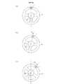
カメラ1は、図2に示すように、車両のステアリングホイール51に設置されており、ステアリングホイール51と共に回転する。カメラ1が設置されている場所は、ステアリングホイール51の回転軸52から離れている。このため、ステアリングホイール51が回転すると、カメラ1は回転軸52を中心に矢印方向へ回転する。図1に示すように、カメラ1には、CMOSイメージセンサのような撮像素子11と、レンズなどを含む光学部品12とが備わっている。 As shown in FIG. 2, the
図3に示すように、カメラ1は、車両50の運転席のシート53に着座している乗員40(運転者)の顔41を撮像する。破線は、カメラ1の撮像範囲を示している。Dは、カメラ1から顔41までの距離を表している。後述するように、距離Dが求まれば、顔41の空間上の位置を特定することができる。車両50は、たとえば自動四輪車である。 As shown in FIG. 3, the
画像処理部2は、画像メモリ21、顔検出部22、第1画像回転部23、第2画像回転部24、および回転角検出部25を備えている。画像メモリ21は、カメラ1が撮像した画像を一時的に保存する。顔検出部22は、カメラ1が撮像した画像から運転者の顔を検出するとともに、顔における特徴点(たとえば目)を抽出する。顔の検出方法や特徴点の抽出方法はよく知られているので、これらの詳細説明は省略する。 The
第1画像回転部23および第2画像回転部24は、カメラ1が撮像した撮像画像G1、G2(後述)を画像メモリ21から読み出して、これらを回転させる処理を行う。回転角検出部25は、画像メモリ21から取得したカメラ1の撮像画像に基づいて、カメラ1の回転角θ1、θ2(後述)を検出する。回転角検出部25で検出された回転角θ1、θ2は、第1画像回転部23および第2画像回転部24へ与えられ、各画像回転部23、24は、これらの回転角θ1、θ2に基づいて、撮像画像G1、G2を所定量回転させる。この画像回転の詳細については後述する。The first
位置算出部3は、第1画像回転部23および第2画像回転部24で生成された回転画像H1、H2(後述)と、顔検出部22で検出された顔の情報(顔領域や特徴点など)に基づき、図3におけるカメラ1から顔41までの距離D、すなわち顔41の空間上の位置を算出する。この詳細についても後述する。位置算出部3の出力は、CAN(Controller Area Network)を介して、車両に搭載されている図示しないECU(Electronic Control Unit)へ送られる。 The
運転者状態判定部4は、顔検出部22から取得した顔の情報に基づいて、瞼の動きや視線の方向などを検出し、その結果に応じて運転者40の状態を判定する。たとえば、瞼が一定時間以上閉じた状態にある場合は、運転者40が居眠りをしていると判定し、視線が横を向いている場合は、運転者40が脇見運転をしていると判定する。運転者状態判定部4の出力は、CANを介してECUへ送られる。 The driver
制御部5は、CPUなどから構成されており、乗員監視装置100の動作を統轄的に制御する。このため、制御部5は、乗員監視装置100の各部と信号線で接続され(図示省略)、各部との間で通信を行う。また、制御部5は、CANを介してECUとも通信を行う。 The
記憶部6は、半導体メモリから構成されており、制御部5を動作させるためのプログラムや、制御に必要なパラメータなどが格納されている。また、記憶部6には、各種のデータが一時的に格納される記憶エリアが設けられている。 The
なお、顔検出部22、第1画像回転部23、第2画像回転部24、回転角検出部25、位置算出部3、および運転者状態判定部4のそれぞれの機能は、実際にはソフトウェアによって実現されるが、図1では便宜上、ブロック図で示している。 The functions of the
次に、上述した乗員監視装置100において顔の空間上の位置を測定する原理について説明する。 Next, a principle of measuring the position of the face in the space in the
図4は、ステアリングホイール51の回転に伴う、カメラ1の位置の変化を示した図である。図4において、(a)はステアリングホイール51が基準位置にある状態、(b)はステアリングホイール51が基準位置から角度θ1だけ回転した状態、(c)はステアリングホイール51がさらに回転して、基準位置から角度θ2まで回転した状態を示している。(b)のカメラ1の位置は、本発明における「第1位置」に相当し、(c)のカメラ1の位置は、本発明における「第2位置」に相当する。FIG. 4 is a diagram illustrating a change in the position of the
図5は、図4の(a)〜(c)の各状態において、カメラ1により撮像した画像の一例を示している。ここでは便宜上、顔の画像のみを示しており、背景画像は省略してある。 FIG. 5 shows an example of an image captured by the
図5(a)は、図4(a)に対応していて、カメラ1が基準位置にある場合の撮像画像である。この画像は、傾きのない正立画像となっている。図5(b)は、図4(b)に対応していて、ステアリングホイール51がθ1回転したことに伴い、カメラ1での撮像画像G1も基準位置からθ1回転したものとなっている。角度θ1は、本発明における「第1回転角」に相当し、撮像画像G1は、本発明における「第1撮像画像」に相当する。図5(c)は、図4(c)に対応していて、ステアリングホイール51がθ2まで回転したことに伴い、カメラ1での撮像画像G2も基準位置からθ2まで回転したものとなっている。角度θ2は、本発明における「第2回転角」に相当し、撮像画像G2は、本発明における「第2撮像画像」に相当する。FIG. 5A corresponds to FIG. 4A and is a captured image when the
図5からわかるように、ステアリングホイール51と共に回転するカメラ1が、異なる位置(回転角度)で撮像した画像は、傾きが異なったものとなり、また、画面上での位置も異なったものとなる。 As can be seen from FIG. 5, images captured by the
本発明では、カメラ1が2つの異なる位置で撮像した2つの画像を用いて、図3で示した距離Dを算出する。カメラ1は1台であるが、カメラ1を移動(回転)させることで、異なる位置における2つの画像が得られる。このため、2台のカメラを用いてステレオ視により距離測定を行う場合と同様の原理(詳細は後述)に基づいて、距離Dの測定が可能となる。このように、1台のカメラを移動させて、擬似的なステレオ視を作り出すことにより距離測定を行う方式を、モーションステレオ方式と呼ぶ。 In the present invention, the distance D shown in FIG. 3 is calculated using two images captured by the
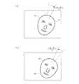
以下、モーションステレオ方式を用いた本発明の距離測定手順について説明する。まず、上述したように、カメラ1が2つの異なる位置で撮像した2つの画像を取得する。ここでは、2つの画像として、カメラ1が図4(b)の回転角θ1の位置で撮像した図5(b)の撮像画像G1と、図4(c)の回転角θ2の位置で撮像した図5(c)の撮像画像G2を用いる。Hereinafter, the distance measurement procedure of the present invention using the motion stereo method will be described. First, as described above, two images captured by the
次に、取得した2つの撮像画像G1、G2を、それぞれ所定量だけ回転させる。詳しくは、撮像画像G1については、図6(a)に示すように、時計回り方向へ|θ2−θ1|/2だけ回転させて、実線で示す回転画像H1を生成する。また、撮像画像G2については、図6(b)に示すように、反時計回り方向へ|θ2−θ1|/2だけ回転させて、実線で示す回転画像H2を生成する。回転画像H1は、本発明における「第1回転画像」に相当し、回転画像H2は、本発明における「第2回転画像」に相当する。時計回り方向は、本発明における「第1方向」に相当し、反時計回り方向は、本発明における「第2方向」に相当する。Next, each of the two captured images G1 and G2 is rotated by a predetermined amount. More specifically, as shown in FIG. 6A, the captured image G1 is rotated clockwise by | θ2 −θ1 | / 2 to generate a rotated image H1 indicated by a solid line. As shown in FIG. 6B, the captured image G2 is rotated counterclockwise by | θ2 −θ1 | / 2 to generate a rotated image H2 indicated by a solid line. The rotated image H1 corresponds to a “first rotated image” in the present invention, and the rotated image H2 corresponds to a “second rotated image” in the present invention. The clockwise direction corresponds to a “first direction” in the present invention, and the counterclockwise direction corresponds to a “second direction” in the present invention.
回転画像H1は、撮像画像G1を画像G1、G2の中間の角度まで回転させた画像であり、回転画像H2も、撮像画像G2を画像G1、G2の中間の角度まで回転させた画像である。したがって、両回転画像H1、H2の画面上での傾きは等しくなる。このように、撮像画像G1、G2を|θ2−θ1|/2の角度だけ逆方向へ回転させることで、通常のステレオカメラで撮像した場合と同様の、姿勢が同じ2つの画像H1、H2を得ることができる。The rotated image H1 is an image obtained by rotating the captured image G1 to an intermediate angle between the images G1 and G2, and the rotated image H2 is an image obtained by rotating the captured image G2 to an intermediate angle between the images G1 and G2. Therefore, the inclinations of the two rotated images H1 and H2 on the screen are equal. In this way, by rotating the captured images G1 and G2 in the opposite direction by an angle of | θ2 −θ1 | / 2, two images H1 and H2 having the same posture as in the case of being captured by a normal stereo camera are obtained. H2 can be obtained.
なお、ここでは、撮像画像G1、G2をそのまま回転させて、回転画像H1、H2を生成したが、図7に示すように、撮像画像G1からたとえば目の領域Zを切り出し、この領域のみを回転させて回転画像を生成してもよい。撮像画像G2についても同様である。 Here, the captured images G1 and G2 are rotated as they are to generate the rotated images H1 and H2. However, as shown in FIG. 7, for example, an eye region Z is cut out from the captured image G1 and only this region is rotated. Alternatively, a rotated image may be generated. The same applies to the captured image G2.
次に、上記のようにして得られた回転画像H1、H2を用いて、ステレオ視による距離演算を行うが、そのためには、まず2つのカメラ位置間の直線距離である「基線長」を求める必要がある。これを図8により説明する。 Next, using the rotated images H1 and H2 obtained as described above, a distance calculation based on stereo vision is performed. For this purpose, first, a "base line length" which is a linear distance between two camera positions is obtained. There is a need. This will be described with reference to FIG.
図8において、Oはステアリングホイール51の回転軸52(図2)の位置、X1は図4(b)におけるカメラ1の位置、X2は図4(c)におけるカメラ1の位置、Lは回転軸52からカメラ位置X1、X2までの距離である。Bはカメラ位置X1、X2間の直線距離であり、これが基線長となる。基線長Bは、図8より幾何学的に、次式で算出される。
B=2・L・sin(|θ2−θ1|/2) ・・・ (1)
ここで、Lは既知であるから、θ1とθ2の値を取得できれば、基線長Bを求めることができる。θ1とθ2は、図5(b)、(c)の撮像画像G1、G2から検出することができる。8, O is the position of the rotation axis 52 (FIG. 2) of the
B = 2 · L · sin (| θ2 −θ1 | / 2) (1)
Here, L is because it is known, if obtaining the value of theta1 and theta2, it is possible to obtain the base length B. theta1 and theta2 is FIG. 5 (b), the can be detected from the captured image G1, G2 of (c).
こうして基線長Bが求まると、次は、一般的なステレオ視による距離測定方法に従い、カメラ1から被写体までの距離を演算する。この距離演算の詳細を、図9を参照しながら説明する。 Once the base line length B is determined in this manner, the distance from the
図9は、ステレオ視による距離演算の原理図を示している。ここでの演算は、三角測量の原理に基づいている。図9において、撮像素子11aおよびレンズ12aを有する第1カメラ1aと、撮像素子11bおよびレンズ12bを有する第2カメラ1bとで、ステレオカメラが構成されている。第1カメラ1aは、図8のX1にあるカメラ1に対応し、第2カメラ1bは、図8のX2にあるカメラ1に対応している。なお、図8のカメラ位置X1、X2は、図9では各カメラ1a、1bの光学中心(レンズ12a、12bの中心)として表されている。この光学中心X1、X2間の距離Bが基線長である。 FIG. 9 shows a principle diagram of distance calculation by stereo vision. The calculation here is based on the principle of triangulation. In FIG. 9, a first camera 1a having an image sensor 11a and a
各カメラ1a、1bで撮像された被写体Yの画像は、撮像素子11a、11bの撮像面上に形成される。ここで、被写体Yの特定部分の画像に着目した場合、第1カメラ1aでは当該画像が撮像面のP1の位置に形成され、第2カメラ1bでは当該画像が撮像面のP2の位置に形成される。P2の位置は、第1カメラ1aにおけるP1に対応するP1’の位置からδだけずれており、このずれ量δを「視差」と呼ぶ。カメラ1a、1bの焦点距離をf、カメラ1a、1bから被写体Yまでの距離をDとしたとき、幾何学的にf/δ=D/Bが成立する。したがって、距離Dは次式で算出される。
D=B・f/δ ・・・ (2)An image of the subject Y captured by each of the
D = B · f / δ (2)
上記(2)式において、基線長Bは前述の(1)式から算出することができ、焦点距離fは既知であるから、視差δを求めることによって、距離Dを算出することができる。視差δは、公知のステレオマッチングの手法を用いて求めることができる。たとえば、第1カメラ1aの撮像画像における特定領域の輝度分布と同じ輝度分布の領域を、第2カメラ1bの撮像画像から探索し、双方の領域のずれ量を視差として求める。 In the above formula (2), the base line length B can be calculated from the above formula (1), and the focal length f is known, so that the distance D can be calculated by obtaining the parallax δ. The parallax δ can be obtained by using a known stereo matching technique. For example, a region having the same luminance distribution as the luminance distribution of the specific region in the image captured by the first camera 1a is searched from the image captured by the
図9の原理に基づき、本発明では、図6に示した回転画像H1、H2から両画像の視差δを検出する。この場合、前述したように、2つの回転画像H1、H2は傾き(姿勢)が同じであるため、両者間のステレオマッチングを容易に行うことができる。そして、マッチングを行う領域を、顔41の特定部分(たとえば目)の領域とすることで、当該特定部分の視差δを用いて、前記(2)式により、カメラ1と顔41の特定部分との間の距離Dを算出することができる。ここで、カメラ1の空間上の位置は、ステアリング51の回転角に応じて定まる。したがって、上記の距離Dを以って、カメラ1から顔41までの距離とすることで、顔41の空間上の位置を特定することが可能となる。 Based on the principle of FIG. 9, in the present invention, a parallax δ between both images is detected from the rotated images H1 and H2 shown in FIG. In this case, as described above, since the two rotated images H1 and H2 have the same inclination (posture), stereo matching between the two can be easily performed. Then, by setting the region to be matched as a region of a specific portion (for example, an eye) of the
図10は、乗員監視装置100の動作を示したフローチャートである。このフローチャートの各ステップは、制御部5の制御の下で、記憶部6に格納されているプログラムに従って実行される。 FIG. 10 is a flowchart showing the operation of the
ステップS1では、カメラ1により撮像を行う。カメラ1が撮像した画像は、画像メモリ21に保存される。ステップS2では、回転角検出部25が、ステアリングホイール51と共に回転するカメラ1の回転角を、カメラ1の撮像画像G1、G2(図5)から検出する。ステップS3では、顔検出部22が、カメラ1の撮像画像から顔を検出する。ステップS4では、顔検出部22が、検出した顔における特徴点(目など)を抽出する。ステップS5では、ステップS2〜S4で取得した回転角、顔画像、特徴点などのデータを記憶部6に保存する。この場合、顔画像や特徴点は、回転角と紐付けされて記憶される。 In step S1, the
ステップS6では、ステップS5で保存したデータを用いてモーションステレオ方式による距離測定が可能か否かを、制御部5が判定する。モーションステレオ方式で被写体までの距離を測定するには、カメラ1が撮像を行った2つの位置が、一定以上離れていることが必要である。また、モーションステレオ方式では、2回の撮像の間に被写体が動かないことが前提となるので、2回の撮像の時間間隔が長いと、被写体が動いて正確な距離測定ができなくなるおそれがある。そこで、ステップS6では、カメラ1が2つの異なる位置の間で、所定時間内(たとえば5秒以内)に所定角度以上(たとえば10°以上)回転した場合に、モーションステレオ方式による距離測定が可能と判定し、所定時間内に所定角度以上回転しなかった場合は、モーションステレオ方式による距離測定が不可能と判定する。 In step S6, the
ステップS6での判定の結果、距離測定が可能であれば(ステップS6:YES)、ステップS7へ進む。ステップS7では、画像回転部23、24により、最新の画像とそれよりN秒前(N≦5)の画像を、|θ2−θ1|/2の角度だけ回転させる処理を行う(|θ2−θ1|≧10°)。たとえば、図5(b)の撮像画像G1は、最新画像よりN秒前の画像であり、第1画像回転部23により、図6(a)のように、時計回り方向へ|θ2−θ1|/2だけ回転させられる。また、図5(c)の撮像画像G2は、最新の画像であり、第2画像回転部24により、図6(b)のように、反時計回り方向へ|θ2−θ1|/2だけ回転させられる。If the result of determination in step S6 is that distance measurement is possible (step S6: YES), control proceeds to step S7. In step S7, the
ステップS8では、位置算出部3が、記憶部6から取得した回転角θ1、θ2に基づいて、前記の(1)式により基線長Bを算出する。ステップS9では、位置算出部3が、画像回転部23、24で生成された各回転画像H1、H2(図6)に基づいて、視差δを算出する。ステップS10では、ステップS8で算出した基線長Bと、ステップS9で算出した視差δと、カメラ1の焦点距離f(既知)とを用いて、前記の(2)式により、カメラ1から顔41までの距離Dを算出する。ステップS11では、ステップS10で算出した距離データを、CANを介してECUへ出力する。ECUは、この距離データに基づいて、たとえば冒頭に述べたHUDの制御などを実行する。In step S <b > 8, the
なお、ステップS6での判定の結果、モーションステレオ方式による距離測定が不可能であれば(ステップS6:NO)、ステップS12へ進む。ステップS12では、撮像画像における顔の大きさの変化に基づき、顔までの距離Dを補正する。詳しくは、モーションステレオ方式による距離測定が可能な場合に(ステップS6:YES)、ステップS10において、算出した距離Dとともに、顔における任意の2箇所の特徴点間の画像上の距離(ピクセル数)を記憶しておく。2箇所の特徴点は、たとえば左右の目のそれぞれの中心である。そして、ステップS12では、今回の特徴点間の距離の前回からの変化分に応じて、ステップS10で算出された前回の距離を補正する。具体的には、前回のステップS10において、特徴点間の距離(ピクセル数)がmで、顔までの距離がDxと算出された場合、今回のステップS12において、特徴点間の距離(ピクセル数)がnであれば、今回の顔までの距離Dyは、Dy=Dx・(m/n)により算出され、これが顔までの距離の補正値となる。一例として、m=100ピクセル、Dx=40cm、n=95ピクセルとした場合、距離の補正値は、Dy=40cm×(100/95)=42.1cmとなる。カメラ1から顔が遠ざかって画像上の顔が小さくなると、これに応じて特徴点間の画像上の距離も小さくなり(n<m)、カメラ1から顔までの距離の算出値が増加する(Dy>Dx)ことがわかる。 If the result of determination in step S6 is that distance measurement by the motion stereo method is not possible (step S6: NO), the flow proceeds to step S12. In step S12, the distance D to the face is corrected based on the change in the size of the face in the captured image. Specifically, when distance measurement by the motion stereo method is possible (step S6: YES), the distance (pixel number) on the image between any two feature points on the face together with the calculated distance D in step S10. Is stored. The two feature points are, for example, the centers of the left and right eyes, respectively. Then, in step S12, the previous distance calculated in step S10 is corrected according to the change in the current distance between the feature points from the previous time. Specifically, if the distance (number of pixels) between feature points is m and the distance to the face is Dx in the previous step S10, the distance (number of pixels) ) Is n, the distance Dy to the face this time is calculated by Dy = Dx · (m / n), and this is a correction value of the distance to the face. As an example, when m = 100 pixels, Dx = 40 cm, and n = 95 pixels, the distance correction value is Dy = 40 cm × (100/95) = 42.1 cm. As the face moves away from the
上述した実施形態によると、ステアリングホイール51における、回転軸52から離れた場所にカメラ1を設置しているので、ステアリングホイール51と共に回転するカメラ1により、2つの異なる位置で撮像した2つの撮像画像G1、G2を得ることができる。そして、これらの撮像画像G1、G2を回転させた回転画像H1、H2を生成し、これらの回転画像H1、H2から得られる視差δを用いて、カメラ1から顔41の特定部分(本例では目)までの距離Dを算出することができる。このため、カメラを複数設けたり、専用の光学系を設けたりする必要がなく、簡単な構成によって顔の空間上の位置を測定できる乗員監視装置が得られる。 According to the above-described embodiment, since the
図11は、本発明の第2実施形態による乗員監視装置200を示している。図11では、図1と同一部分に同一符号を付してある。 FIG. 11 shows an
図1の乗員監視装置100では、回転角検出部25が、画像メモリ21から取得したカメラ1の撮像画像(顔の画像以外に背景の画像も含む)に基づいて、カメラ1の回転角θ1、θ2を検出した。これに対して、図11の乗員監視装置200では、回転角検出部25が、顔検出部22で検出された顔の画像に基づいて、カメラ1の回転角θ1、θ2を検出する。また、画像回転部23、24は、顔検出部22で検出された顔の画像に対して回転処理を行って、回転画像H1、H2を生成する。この場合、回転画像H1、H2には顔の情報が反映されているので、位置算出部3は、顔検出部22から顔の情報を取得する必要がない。In the
図11の乗員監視装置200においても、図1の場合と同様の原理に基づいて、カメラ1から顔41までの距離Dを算出することができる。 The
図12は、本発明の第3実施形態による乗員監視装置300を示している。図12では、図1と同一部分に同一符号を付してある。 FIG. 12 shows an
図1の乗員監視装置100では、回転角検出部25が、カメラ1で撮像された画像に基づいて、カメラ1の回転角θ1、θ2を検出した。これに対して、図12の乗員監視装置300では、回転角検出部25が、カメラ1に設けられた姿勢センサ13の出力に基づいて、カメラ1の回転角θ1、θ2を検出する。姿勢センサ13としては、ジャイロセンサなどを用いることができる。In the
図13は、本発明の第4実施形態による乗員監視装置400を示している。図13では、図1と同一部分に同一符号を付してある。 FIG. 13 shows an
図12の乗員監視装置300では、回転角検出部25が、姿勢センサ13の出力に基づいて、カメラ1の回転角θ1、θ2を検出した。これに対して、図13の乗員監視装置400では、回転角検出部25が、ステアリングホイール51の操舵角を検出する操舵角センサ30の出力に基づいて、カメラ1の回転角θ1、θ2を検出する。操舵角センサ30としては、ロータリエンコーダなどを用いることができる。In the
図12および図13の乗員監視装置300、400においても、図1の場合と同様の原理に基づいて、カメラ1から顔41までの距離Dを算出することができる。 The
なお、図12および図13において、図11のように、画像回転部23、24が、顔検出部22から取得した顔の画像に対して回転処理を行って、回転画像H1、H2を生成してもよい。 In FIGS. 12 and 13, as shown in FIG. 11, the
本発明では、上述した実施形態以外にも、以下のような種々の実施形態を採用することができる。 In the present invention, in addition to the above-described embodiments, the following various embodiments can be adopted.
上述した実施形態では、カメラ1を、ステアリングホイール51における図2の位置に設置した例を挙げたが、カメラ1は、ステアリングホイール51上の、回転軸52から離れた位置に設置すればよく、図2の位置に限定されない。 In the above-described embodiment, an example in which the
上述した実施形態では、撮像画像G1を時計回り方向に|θ2−θ1|/2の角度だけ回転させ、撮像画像G2を反時計回り方向に|θ2−θ1|/2の角度だけ回転させた例を挙げたが(図6)、本発明はこれに限定されない。たとえば、撮像画像G1を、時計回り方向に|θ2−θ1|回転させて、撮像画像G2と同じ傾きの画像にしてもよい。あるいは、撮像画像G2を、反時計回り方向に|θ2−θ1|回転させて、撮像画像G1と同じ傾きの画像にしてもよい。In the above-described embodiment, the captured image G1 is rotated clockwise by an angle of | θ2 −θ1 | / 2, and the captured image G2 is rotated counterclockwise by an angle of | θ2 −θ1 | / 2. Although an example of rotation is shown (FIG. 6), the present invention is not limited to this. For example, the captured image G1 may be rotated clockwise by | θ2 −θ1 | to obtain an image having the same inclination as the captured image G2. Alternatively, the captured image G2 may be rotated by | θ2 −θ1 | in the counterclockwise direction to make an image having the same inclination as the captured image G1.
上述した実施形態では、カメラ1から顔41までの距離Dを算出するにあたって、顔41の特定部分として目を例に挙げたが、特定部分は目に限らず、鼻、口、耳、眉などであってもよい。また、特定部分は、目、鼻、口、耳、眉などの顔の特徴点に限らず、特徴点以外の任意点であってもよい。さらに、本発明において距離測定の対象となる部位は、顔に限らず、頭や首などの他の部位であってもよい。 In the above-described embodiment, when calculating the distance D from the
上述した実施形態では、カメラ1から顔41までの距離Dを、顔41の空間上の位置としたが、空間上の位置は、距離に限らず座標値で表してもよい。 In the above-described embodiment, the distance D from the
上述した実施形態では、乗員監視装置100〜400に運転者状態判定部4が設けられている例を挙げたが、運転者状態判定部4は、乗員監視装置100〜400の外部に設けてもよい。 In the above-described embodiment, the example in which the driver
1 カメラ
2 画像処理部
3 位置算出部
13 姿勢センサ
22 顔検出部
25 回転角検出部
30 操舵センサ
40 乗員
41 顔
50 車両
51 ステアリングホイール
52 回転軸
100、200、300、400 乗員監視装置
B 基線長
δ 視差
f 焦点距離
L ステアリングホイールの回転軸からカメラまでの距離
D カメラから被写体までの距離
θ1 第1回転角
θ2 第2回転角
G1 第1撮像画像
G2 第2撮像画像
H1 第1回転画像
H2 第2回転画像
Claims (8)
Translated fromJapanese前記カメラで撮像された乗員の画像に対して所定の処理を行う画像処理部と、
前記画像処理部で処理された画像に基づいて、前記乗員の所定部位の空間上の位置を算出する位置算出部と、を備え、
前記カメラは、前記車両のステアリングホイールにおける、回転軸から離れた場所に設置されていて、前記ステアリングホイールと共に回転し、
前記画像処理部は、前記ステアリングホイールの回転に伴って前記カメラが2つの異なる位置で撮像した、2つの画像に対して所定の処理を行い、
前記位置算出部は、前記画像処理部で処理された2つの画像に基づいて、前記所定部位の空間上の位置を算出する、ことを特徴とする乗員監視装置。A camera for imaging the occupants of the vehicle,
An image processing unit that performs predetermined processing on the image of the occupant captured by the camera,
A position calculating unit that calculates a spatial position of the occupant's predetermined part based on the image processed by the image processing unit,
The camera is installed at a location away from a rotation axis on a steering wheel of the vehicle, and rotates together with the steering wheel.
The image processing unit performs a predetermined process on two images captured by the camera at two different positions with the rotation of the steering wheel,
The occupant monitoring device, wherein the position calculation unit calculates a position of the predetermined part in space based on the two images processed by the image processing unit.
前記画像処理部は、前記カメラで撮像された画像から乗員の顔を検出する顔検出部を有し、
前記位置算出部は、前記カメラから前記顔の特定部分までの距離を、当該顔の空間上の位置として算出する、ことを特徴とする乗員監視装置。The occupant monitoring device according to claim 1,
The image processing unit has a face detection unit that detects an occupant's face from an image captured by the camera,
The occupant monitoring device, wherein the position calculation unit calculates a distance from the camera to a specific portion of the face as a position of the face in space.
前記2つの画像は、前記カメラが第1回転角だけ回転したときの第1位置で撮像した第1撮像画像、および前記カメラが第2回転角だけ回転したときの第2位置で撮像した第2撮像画像であり、
前記画像処理部は、前記第1撮像画像を所定量回転させた第1回転画像、および前記第2撮像画像を所定量回転させた第2回転画像を生成し、
前記位置算出部は、前記第1位置と前記第2位置との間の直線距離である基線長と、前記第1回転画像および前記第2回転画像から得られる視差と、前記カメラの焦点距離とに基づいて、前記所定部位の空間上の位置を算出する、ことを特徴とする乗員監視装置。The occupant monitoring device according to claim 1 or 2,
The two images are a first captured image captured at a first position when the camera is rotated by a first rotation angle, and a second captured image at a second position when the camera is rotated by a second rotation angle. A captured image,
The image processing unit generates a first rotated image obtained by rotating the first captured image by a predetermined amount, and a second rotated image obtained by rotating the second captured image by a predetermined amount,
The position calculation unit is configured to calculate a base line length that is a linear distance between the first position and the second position, a parallax obtained from the first rotation image and the second rotation image, and a focal length of the camera. An occupant monitoring device, wherein a position in the space of the predetermined part is calculated based on the information.
前記ステアリングホイールの回転軸から前記カメラまでの距離をL、前記第1回転角をθ1、前記第2回転角をθ2、前記基線長をB、前記視差をδ、前記焦点距離をfとし、前記所定部位の空間上の位置を、前記カメラから当該所定部位までの距離Dとしたとき、
前記画像処理部は、
前記第1撮像画像を、第1方向へ|θ2−θ1|/2の角度だけ回転させて、前記第1回転画像を生成し、
前記第2撮像画像を、前記第1方向と逆の第2方向へ|θ2−θ1|/2の角度だけ回転させて、前記第2回転画像を生成し、
前記位置算出部は、
前記基線長を、B=2・L・sin(|θ2−θ1|/2)により算出し、
前記所定部位の空間上の位置を、D=B・(f/δ)により算出する、ことを特徴とする乗員監視装置。The occupant monitoring device according to claim 3,
The distance from the rotation axis of the steering wheel to the camera is L, the first rotation angle is θ1 , the second rotation angle is θ2 , the base line length is B, the parallax is δ, and the focal length is f. , When the position in the space of the predetermined part is a distance D from the camera to the predetermined part,
The image processing unit,
Rotating the first captured image in the first direction by an angle of | θ2 −θ1 | / 2 to generate the first rotated image;
Rotating the second captured image by an angle of | θ2 −θ1 | / 2 in a second direction opposite to the first direction to generate the second rotated image;
The position calculation unit,
The base length is calculated by B = 2 · L · sin (| θ2 −θ1 | / 2),
An occupant monitoring device, wherein a position in the space of the predetermined part is calculated by D = B · (f / δ).
前記カメラの回転角を検出する回転角検出部を備え、
前記回転角検出部は、前記カメラから取得した前記第1撮像画像および前記第2撮像画像に基づいて、前記第1回転角および前記第2回転角を検出する、ことを特徴とする乗員監視装置。The occupant monitoring device according to claim 3 or 4,
A rotation angle detection unit that detects a rotation angle of the camera,
The occupant monitoring device, wherein the rotation angle detection unit detects the first rotation angle and the second rotation angle based on the first captured image and the second captured image acquired from the camera. .
前記カメラの回転角を検出する回転角検出部を備え、
前記回転角検出部は、前記カメラの姿勢を検出する姿勢センサの出力に基づいて、前記第1回転角および前記第2回転角を検出する、ことを特徴とする乗員監視装置。The occupant monitoring device according to claim 3 or 4,
A rotation angle detection unit that detects a rotation angle of the camera,
The occupant monitoring device, wherein the rotation angle detector detects the first rotation angle and the second rotation angle based on an output of a posture sensor that detects a posture of the camera.
前記カメラの回転角を検出する回転角検出部を備え、
前記回転角検出部は、前記ステアリングホイールの操舵角を検出する操舵角センサの出力に基づいて、前記第1回転角および前記第2回転角を検出する、ことを特徴とする乗員監視装置。The occupant monitoring device according to claim 3 or 4,
A rotation angle detection unit that detects a rotation angle of the camera,
The occupant monitoring device according to claim 1, wherein the rotation angle detection unit detects the first rotation angle and the second rotation angle based on an output of a steering angle sensor that detects a steering angle of the steering wheel.
前記位置算出部は、
前記カメラが、前記2つの異なる位置の間で、所定時間内に所定角度以上回転した場合に、前記2つの画像に基づいて前記所定部位の空間上の位置を算出する、ことを特徴とする乗員監視装置。The occupant monitoring device according to any one of claims 1 to 7,
The position calculation unit,
An occupant, wherein, when the camera is rotated by a predetermined angle or more within a predetermined time between the two different positions, a position in the space of the predetermined part is calculated based on the two images. Monitoring device.
Priority Applications (4)
| Application Number | Priority Date | Filing Date | Title |
|---|---|---|---|
| JP2018033132AJP6669182B2 (en) | 2018-02-27 | 2018-02-27 | Occupant monitoring device |
| US16/260,228US20190266743A1 (en) | 2018-02-27 | 2019-01-29 | Occupant monitoring apparatus |
| CN201910090311.4ACN110194173B (en) | 2018-02-27 | 2019-01-30 | Occupant monitoring device |
| DE102019103197.4ADE102019103197B4 (en) | 2018-02-27 | 2019-02-08 | OCCUPANT MONITORING DEVICE |
Applications Claiming Priority (1)
| Application Number | Priority Date | Filing Date | Title |
|---|---|---|---|
| JP2018033132AJP6669182B2 (en) | 2018-02-27 | 2018-02-27 | Occupant monitoring device |
Publications (2)
| Publication Number | Publication Date |
|---|---|
| JP2019148491A JP2019148491A (en) | 2019-09-05 |
| JP6669182B2true JP6669182B2 (en) | 2020-03-18 |
Family
ID=67550240
Family Applications (1)
| Application Number | Title | Priority Date | Filing Date |
|---|---|---|---|
| JP2018033132AExpired - Fee RelatedJP6669182B2 (en) | 2018-02-27 | 2018-02-27 | Occupant monitoring device |
Country Status (4)
| Country | Link |
|---|---|
| US (1) | US20190266743A1 (en) |
| JP (1) | JP6669182B2 (en) |
| CN (1) | CN110194173B (en) |
| DE (1) | DE102019103197B4 (en) |
Families Citing this family (5)
| Publication number | Priority date | Publication date | Assignee | Title |
|---|---|---|---|---|
| US10891502B1 (en)* | 2017-01-19 | 2021-01-12 | State Farm Mutual Automobile Insurance Company | Apparatuses, systems and methods for alleviating driver distractions |
| US11527081B2 (en)* | 2020-10-20 | 2022-12-13 | Toyota Research Institute, Inc. | Multiple in-cabin cameras and lighting sources for driver monitoring |
| DE112020007803T5 (en)* | 2020-11-27 | 2023-11-16 | Mitsubishi Electric Corporation | Sleep detection device and sleep detection method |
| CN112667084B (en)* | 2020-12-31 | 2023-04-07 | 上海商汤临港智能科技有限公司 | Control method and device for vehicle-mounted display screen, electronic equipment and storage medium |
| US12307790B2 (en)* | 2022-09-01 | 2025-05-20 | Ford Global Technologies, Llc | Steering wheel contact detection |
Family Cites Families (15)
| Publication number | Priority date | Publication date | Assignee | Title |
|---|---|---|---|---|
| JP2004198732A (en)* | 2002-12-18 | 2004-07-15 | Sony Computer Entertainment Inc | Photographic aid, method and apparatus for image processing, computer program, and recording medium with recorded program |
| JP4380412B2 (en)* | 2004-05-10 | 2009-12-09 | 株式会社デンソー | Imaging control apparatus and program |
| JP4706917B2 (en)* | 2005-09-07 | 2011-06-22 | アイシン精機株式会社 | Driver monitoring system |
| JP4735361B2 (en)* | 2006-03-23 | 2011-07-27 | 日産自動車株式会社 | Vehicle occupant face orientation detection device and vehicle occupant face orientation detection method |
| WO2009116242A1 (en)* | 2008-03-18 | 2009-09-24 | パナソニック株式会社 | Driver monitoring apparatus, driver monitoring method, and vehicle |
| KR100921092B1 (en)* | 2008-07-04 | 2009-10-08 | 현대자동차주식회사 | Driver condition monitoring system using camera mounted on the steering wheel |
| JP4911230B2 (en)* | 2010-02-01 | 2012-04-04 | カシオ計算機株式会社 | Imaging apparatus, control program, and control method |
| US9041789B2 (en)* | 2011-03-25 | 2015-05-26 | Tk Holdings Inc. | System and method for determining driver alertness |
| JP2013078039A (en)* | 2011-09-30 | 2013-04-25 | Sharp Corp | Electronic apparatus capable of acquiring three-dimensional image, method for controlling the same, and program for controlling the same |
| US9405982B2 (en)* | 2013-01-18 | 2016-08-02 | GM Global Technology Operations LLC | Driver gaze detection system |
| TW201441075A (en)* | 2013-04-23 | 2014-11-01 | Hon Hai Prec Ind Co Ltd | System and method for controlling airbags of a vehicle |
| DE102014214352A1 (en)* | 2014-07-23 | 2016-01-28 | Robert Bosch Gmbh | Method and arrangement for operating an occupant observation system |
| JP2016032257A (en)* | 2014-07-30 | 2016-03-07 | 株式会社デンソー | Driver monitoring device |
| US9533687B2 (en)* | 2014-12-30 | 2017-01-03 | Tk Holdings Inc. | Occupant monitoring systems and methods |
| CN107187490A (en)* | 2017-06-01 | 2017-09-22 | 北京汽车研究总院有限公司 | A kind of steering wheel, automobile and monitoring method |
- 2018
- 2018-02-27JPJP2018033132Apatent/JP6669182B2/ennot_activeExpired - Fee Related
- 2019
- 2019-01-29USUS16/260,228patent/US20190266743A1/ennot_activeAbandoned
- 2019-01-30CNCN201910090311.4Apatent/CN110194173B/enactiveActive
- 2019-02-08DEDE102019103197.4Apatent/DE102019103197B4/enactiveActive
Also Published As
| Publication number | Publication date |
|---|---|
| CN110194173A (en) | 2019-09-03 |
| US20190266743A1 (en) | 2019-08-29 |
| JP2019148491A (en) | 2019-09-05 |
| DE102019103197A1 (en) | 2019-08-29 |
| CN110194173B (en) | 2022-06-10 |
| DE102019103197B4 (en) | 2020-12-17 |
Similar Documents
| Publication | Publication Date | Title |
|---|---|---|
| JP6669182B2 (en) | Occupant monitoring device | |
| JP7161410B2 (en) | System and method for identifying camera pose in scene | |
| US10311735B2 (en) | Vehicle display system and method of controlling vehicle display system | |
| JP5230748B2 (en) | Gaze direction determination device and gaze direction determination method | |
| JP4690476B2 (en) | Car camera calibration system | |
| JP5491235B2 (en) | Camera calibration device | |
| CN108621940B (en) | Display system for vehicle and control method for display system for vehicle | |
| JP6364627B2 (en) | Gaze direction detection device and gaze direction detection method | |
| JP5455124B2 (en) | Camera posture parameter estimation device | |
| TWI574224B (en) | An image processing apparatus, an image processing method, a video product processing apparatus, a recording medium, and an image display apparatus | |
| JP6596678B2 (en) | Gaze measurement apparatus and gaze measurement method | |
| JP2011151666A (en) | Device, system and method for acquiring parameter, and program | |
| CN110310321B (en) | Sight direction estimating device, sight direction estimating method, and program product | |
| KR20200071960A (en) | Method and Apparatus for Vehicle Detection Using Lidar Sensor and Camera Convergence | |
| WO2015029443A1 (en) | Turning angle correction method, turning angle correction device, image-capturing device, and turning angle correction system | |
| JP6479272B1 (en) | Gaze direction calibration apparatus, gaze direction calibration method, and gaze direction calibration program | |
| WO2018222122A1 (en) | Methods for perspective correction, computer program products and systems | |
| CN114463371B (en) | Object tracking method and processing device and system | |
| JP6161704B2 (en) | Imaging apparatus, vehicle, and image correction method | |
| JP2018151930A (en) | Driver state estimation device and driver state estimation method | |
| JP2006268076A (en) | Driving assistance system | |
| JP2018101212A (en) | On-vehicle device and method for calculating degree of face directed to front side | |
| CN118159892A (en) | Method and device for determining the installation attitude of a vehicle-mounted inertial sensor device in a motor vehicle | |
| WO2023067867A1 (en) | Vehicle-mounted control device, and three-dimensional information acquisition method | |
| JP2018101211A (en) | On-vehicle device |
Legal Events
| Date | Code | Title | Description |
|---|---|---|---|
| A711 | Notification of change in applicant | Free format text:JAPANESE INTERMEDIATE CODE: A711 Effective date:20190311 | |
| A621 | Written request for application examination | Free format text:JAPANESE INTERMEDIATE CODE: A621 Effective date:20190319 | |
| TRDD | Decision of grant or rejection written | ||
| A977 | Report on retrieval | Free format text:JAPANESE INTERMEDIATE CODE: A971007 Effective date:20200122 | |
| A01 | Written decision to grant a patent or to grant a registration (utility model) | Free format text:JAPANESE INTERMEDIATE CODE: A01 Effective date:20200128 | |
| A61 | First payment of annual fees (during grant procedure) | Free format text:JAPANESE INTERMEDIATE CODE: A61 Effective date:20200210 | |
| R150 | Certificate of patent or registration of utility model | Ref document number:6669182 Country of ref document:JP Free format text:JAPANESE INTERMEDIATE CODE: R150 | |
| LAPS | Cancellation because of no payment of annual fees |