JP6668902B2 - Positioning device and method of operating positioning device - Google Patents
Positioning device and method of operating positioning deviceDownload PDFInfo
- Publication number
- JP6668902B2 JP6668902B2JP2016079445AJP2016079445AJP6668902B2JP 6668902 B2JP6668902 B2JP 6668902B2JP 2016079445 AJP2016079445 AJP 2016079445AJP 2016079445 AJP2016079445 AJP 2016079445AJP 6668902 B2JP6668902 B2JP 6668902B2
- Authority
- JP
- Japan
- Prior art keywords
- unit
- optimization
- dimensional
- subject
- positioning
- Prior art date
- Legal status (The legal status is an assumption and is not a legal conclusion. Google has not performed a legal analysis and makes no representation as to the accuracy of the status listed.)
- Active
Links
Images


Classifications
- A—HUMAN NECESSITIES
- A61—MEDICAL OR VETERINARY SCIENCE; HYGIENE
- A61N—ELECTROTHERAPY; MAGNETOTHERAPY; RADIATION THERAPY; ULTRASOUND THERAPY
- A61N5/00—Radiation therapy
- A61N5/10—X-ray therapy; Gamma-ray therapy; Particle-irradiation therapy
- A61N5/1048—Monitoring, verifying, controlling systems and methods
- A61N5/1049—Monitoring, verifying, controlling systems and methods for verifying the position of the patient with respect to the radiation beam
- A—HUMAN NECESSITIES
- A61—MEDICAL OR VETERINARY SCIENCE; HYGIENE
- A61B—DIAGNOSIS; SURGERY; IDENTIFICATION
- A61B6/00—Apparatus or devices for radiation diagnosis; Apparatus or devices for radiation diagnosis combined with radiation therapy equipment
- A61B6/02—Arrangements for diagnosis sequentially in different planes; Stereoscopic radiation diagnosis
- A61B6/03—Computed tomography [CT]
- A61B6/032—Transmission computed tomography [CT]
- A—HUMAN NECESSITIES
- A61—MEDICAL OR VETERINARY SCIENCE; HYGIENE
- A61B—DIAGNOSIS; SURGERY; IDENTIFICATION
- A61B6/00—Apparatus or devices for radiation diagnosis; Apparatus or devices for radiation diagnosis combined with radiation therapy equipment
- A61B6/04—Positioning of patients; Tiltable beds or the like
- A61B6/0407—Supports, e.g. tables or beds, for the body or parts of the body
- A—HUMAN NECESSITIES
- A61—MEDICAL OR VETERINARY SCIENCE; HYGIENE
- A61B—DIAGNOSIS; SURGERY; IDENTIFICATION
- A61B6/00—Apparatus or devices for radiation diagnosis; Apparatus or devices for radiation diagnosis combined with radiation therapy equipment
- A61B6/40—Arrangements for generating radiation specially adapted for radiation diagnosis
- A61B6/4007—Arrangements for generating radiation specially adapted for radiation diagnosis characterised by using a plurality of source units
- A61B6/4014—Arrangements for generating radiation specially adapted for radiation diagnosis characterised by using a plurality of source units arranged in multiple source-detector units
- A—HUMAN NECESSITIES
- A61—MEDICAL OR VETERINARY SCIENCE; HYGIENE
- A61B—DIAGNOSIS; SURGERY; IDENTIFICATION
- A61B6/00—Apparatus or devices for radiation diagnosis; Apparatus or devices for radiation diagnosis combined with radiation therapy equipment
- A61B6/52—Devices using data or image processing specially adapted for radiation diagnosis
- A61B6/5205—Devices using data or image processing specially adapted for radiation diagnosis involving processing of raw data to produce diagnostic data
- A—HUMAN NECESSITIES
- A61—MEDICAL OR VETERINARY SCIENCE; HYGIENE
- A61B—DIAGNOSIS; SURGERY; IDENTIFICATION
- A61B6/00—Apparatus or devices for radiation diagnosis; Apparatus or devices for radiation diagnosis combined with radiation therapy equipment
- A61B6/52—Devices using data or image processing specially adapted for radiation diagnosis
- A61B6/5211—Devices using data or image processing specially adapted for radiation diagnosis involving processing of medical diagnostic data
- A61B6/5229—Devices using data or image processing specially adapted for radiation diagnosis involving processing of medical diagnostic data combining image data of a patient, e.g. combining a functional image with an anatomical image
- A—HUMAN NECESSITIES
- A61—MEDICAL OR VETERINARY SCIENCE; HYGIENE
- A61N—ELECTROTHERAPY; MAGNETOTHERAPY; RADIATION THERAPY; ULTRASOUND THERAPY
- A61N5/00—Radiation therapy
- A61N5/10—X-ray therapy; Gamma-ray therapy; Particle-irradiation therapy
- A—HUMAN NECESSITIES
- A61—MEDICAL OR VETERINARY SCIENCE; HYGIENE
- A61N—ELECTROTHERAPY; MAGNETOTHERAPY; RADIATION THERAPY; ULTRASOUND THERAPY
- A61N5/00—Radiation therapy
- A61N5/10—X-ray therapy; Gamma-ray therapy; Particle-irradiation therapy
- A61N5/1001—X-ray therapy; Gamma-ray therapy; Particle-irradiation therapy using radiation sources introduced into or applied onto the body; brachytherapy
- A—HUMAN NECESSITIES
- A61—MEDICAL OR VETERINARY SCIENCE; HYGIENE
- A61N—ELECTROTHERAPY; MAGNETOTHERAPY; RADIATION THERAPY; ULTRASOUND THERAPY
- A61N5/00—Radiation therapy
- A61N5/10—X-ray therapy; Gamma-ray therapy; Particle-irradiation therapy
- A61N5/103—Treatment planning systems
- A—HUMAN NECESSITIES
- A61—MEDICAL OR VETERINARY SCIENCE; HYGIENE
- A61N—ELECTROTHERAPY; MAGNETOTHERAPY; RADIATION THERAPY; ULTRASOUND THERAPY
- A61N5/00—Radiation therapy
- A61N5/10—X-ray therapy; Gamma-ray therapy; Particle-irradiation therapy
- A61N5/103—Treatment planning systems
- A61N5/1031—Treatment planning systems using a specific method of dose optimization
- A—HUMAN NECESSITIES
- A61—MEDICAL OR VETERINARY SCIENCE; HYGIENE
- A61N—ELECTROTHERAPY; MAGNETOTHERAPY; RADIATION THERAPY; ULTRASOUND THERAPY
- A61N5/00—Radiation therapy
- A61N5/10—X-ray therapy; Gamma-ray therapy; Particle-irradiation therapy
- A61N5/1048—Monitoring, verifying, controlling systems and methods
- A61N5/1064—Monitoring, verifying, controlling systems and methods for adjusting radiation treatment in response to monitoring
- A61N5/1069—Target adjustment, e.g. moving the patient support
- A61N5/107—Target adjustment, e.g. moving the patient support in real time, i.e. during treatment
- A—HUMAN NECESSITIES
- A61—MEDICAL OR VETERINARY SCIENCE; HYGIENE
- A61B—DIAGNOSIS; SURGERY; IDENTIFICATION
- A61B6/00—Apparatus or devices for radiation diagnosis; Apparatus or devices for radiation diagnosis combined with radiation therapy equipment
- A61B6/04—Positioning of patients; Tiltable beds or the like
- A61B6/0487—Motor-assisted positioning
- A—HUMAN NECESSITIES
- A61—MEDICAL OR VETERINARY SCIENCE; HYGIENE
- A61B—DIAGNOSIS; SURGERY; IDENTIFICATION
- A61B6/00—Apparatus or devices for radiation diagnosis; Apparatus or devices for radiation diagnosis combined with radiation therapy equipment
- A61B6/52—Devices using data or image processing specially adapted for radiation diagnosis
- A61B6/5211—Devices using data or image processing specially adapted for radiation diagnosis involving processing of medical diagnostic data
- A61B6/5229—Devices using data or image processing specially adapted for radiation diagnosis involving processing of medical diagnostic data combining image data of a patient, e.g. combining a functional image with an anatomical image
- A61B6/5235—Devices using data or image processing specially adapted for radiation diagnosis involving processing of medical diagnostic data combining image data of a patient, e.g. combining a functional image with an anatomical image combining images from the same or different ionising radiation imaging techniques, e.g. PET and CT
- A—HUMAN NECESSITIES
- A61—MEDICAL OR VETERINARY SCIENCE; HYGIENE
- A61B—DIAGNOSIS; SURGERY; IDENTIFICATION
- A61B6/00—Apparatus or devices for radiation diagnosis; Apparatus or devices for radiation diagnosis combined with radiation therapy equipment
- A61B6/52—Devices using data or image processing specially adapted for radiation diagnosis
- A61B6/5258—Devices using data or image processing specially adapted for radiation diagnosis involving detection or reduction of artifacts or noise
- A61B6/5264—Devices using data or image processing specially adapted for radiation diagnosis involving detection or reduction of artifacts or noise due to motion
- A—HUMAN NECESSITIES
- A61—MEDICAL OR VETERINARY SCIENCE; HYGIENE
- A61N—ELECTROTHERAPY; MAGNETOTHERAPY; RADIATION THERAPY; ULTRASOUND THERAPY
- A61N5/00—Radiation therapy
- A61N5/10—X-ray therapy; Gamma-ray therapy; Particle-irradiation therapy
- A61N5/1048—Monitoring, verifying, controlling systems and methods
- A61N5/1049—Monitoring, verifying, controlling systems and methods for verifying the position of the patient with respect to the radiation beam
- A61N2005/1061—Monitoring, verifying, controlling systems and methods for verifying the position of the patient with respect to the radiation beam using an x-ray imaging system having a separate imaging source
- A61N2005/1062—Monitoring, verifying, controlling systems and methods for verifying the position of the patient with respect to the radiation beam using an x-ray imaging system having a separate imaging source using virtual X-ray images, e.g. digitally reconstructed radiographs [DRR]
Landscapes
- Health & Medical Sciences (AREA)
- Engineering & Computer Science (AREA)
- Life Sciences & Earth Sciences (AREA)
- Biomedical Technology (AREA)
- Medical Informatics (AREA)
- Veterinary Medicine (AREA)
- Animal Behavior & Ethology (AREA)
- Nuclear Medicine, Radiotherapy & Molecular Imaging (AREA)
- Public Health (AREA)
- Pathology (AREA)
- Radiology & Medical Imaging (AREA)
- General Health & Medical Sciences (AREA)
- Surgery (AREA)
- Molecular Biology (AREA)
- High Energy & Nuclear Physics (AREA)
- Heart & Thoracic Surgery (AREA)
- Biophysics (AREA)
- Optics & Photonics (AREA)
- Physics & Mathematics (AREA)
- Computer Vision & Pattern Recognition (AREA)
- Pulmonology (AREA)
- Theoretical Computer Science (AREA)
- Radiation-Therapy Devices (AREA)
- Apparatus For Radiation Diagnosis (AREA)
Description
Translated fromJapaneseこの発明は、患者に対して放射線治療を行うときに患者の位置決めを行う位置決め装置および位置決め装置の作動方法に関する。The present invention relates to a positioning device for positioning a patient when performing radiotherapy on the patient, and a methodof operating the positioningdevice .
患者の患部に向けて、X線、電子線、粒子線等の放射線を照射する放射線治療においては、治療用放射線を患部に正確に照射する必要がある。このような放射線治療では、まずX線CT撮像が行われ、治療計画が策定される。そして、放射線治療装置による治療を実行するときには、治療計画時にX線CT装置により収集された3次元画像データに対して仮想的透視投影が行われ、DRR(Degital Reconstructed Radiography:デジタル再投影画像)が作成される。 2. Description of the Related Art In radiotherapy for irradiating an affected part of a patient with radiation such as an X-ray, an electron beam, or a particle beam, it is necessary to accurately irradiate therapeutic radiation to the affected part. In such radiation treatment, first, X-ray CT imaging is performed, and a treatment plan is formulated. Then, when performing treatment by the radiation therapy apparatus, virtual perspective projection is performed on three-dimensional image data acquired by the X-ray CT apparatus at the time of treatment planning, and DRR (Digital Reconstructed Radiography: digital reprojection image) is obtained. Created.
患者(被検体)の位置決めを行う位置決め装置では、放射線治療装置の治療台に固定具で拘束された患者の患部およびその周辺のX線透視画像と、DRRとの類似度が最大となるように透視投影パラメータの最適化演算が行われる。そして、X線透視画像にDRRを位置合わせすることで、患者の放射線治療時の位置と治療計画時の位置とのずれ量を算出し、それを治療台の移動量に反映している(特許文献1から特許文献4参照)。 In a positioning device for positioning a patient (subject), an X-ray fluoroscopic image of an affected part of the patient and its surroundings, which is restrained by a fixture on a treatment table of the radiation therapy apparatus, and the similarity between the DRR and the X-ray image are maximized. An operation for optimizing perspective projection parameters is performed. Then, by aligning the DRR with the X-ray fluoroscopic image, the amount of deviation between the position of the patient at the time of radiotherapy and the position at the time of treatment planning is calculated, and this is reflected in the amount of movement of the treatment table.
特許文献1から特許文献3の放射線治療装置のように、治療台上の患者に対して、正側2方向(水平方向と垂直方向)からX線透視を行う場合と比較して、特許文献4の放射線治療装置のように、患者に対して傾斜角を持った2方向からX線透視を行う場合には、SID(Source Image Distance:線源受像面間距離)が長くなる。このようにSIDが長い場合には、実透視像であるX線透視画像と仮想投影像であるDRRとの位置合わせの最適化演算の進行が停滞し、位置合わせに時間がかかる、もしくは、位置決め精度が低下することがあった。 Compared with the case of performing X-ray fluoroscopy on a patient on a treatment table from two front sides (horizontal direction and vertical direction) as in the radiotherapy apparatuses of
図7および図8は、被検体に対して傾斜角を持った2方向からのX線透視を行った場合のX線透視画像を模式的に示す説明図である。図7は、撮影方向と被検体の位置を説明する図であり、図8は、図7に1、2、3の数字で示す被検体の位置での撮影方向AおよびBの各X線透視画像にDRRを重ね合わせた像を示すものである。なお、図8においては、DRRの輪郭を実線で示し、X線透視画像の輪郭を破線で示している。 7 and 8 are explanatory diagrams schematically showing X-ray fluoroscopic images when X-ray fluoroscopy is performed on the subject from two directions having tilt angles. FIG. 7 is a view for explaining the imaging direction and the position of the subject. FIG. 8 is a view showing the X-ray fluoroscopy in the imaging directions A and B at the positions of the subject indicated by
X線透視画像とDRRの位置合わせは、2方向の画像の類似度の和が最大となる位置の探索を、類似度の和の反数を目的関数(評価関数)として、これを最小化する最適化問題を解くことに帰着する。被検体の位置が撮影方向AとBの交点である1の位置(図7参照)であるときには、方向A、BのどちらもX線透視画像とDRRとに位置ずれがなく(図8上段参照)、いずれの方向においても画像の類似度が大きくなる。すなわち、評価関数値が最も小さくなる状態である。被検体の位置が撮影方向A、Bのいずれからもずれている2の位置(図7参照)であるときには、方向A、BのどちらもX線透視画像とDRRとに位置ずれがあり(図8中段参照)、いずれの方向においても画像の類似度が大きくないため、この場合には、さらに最適化演算が続行される。 The alignment between the X-ray fluoroscopic image and the DRR minimizes the search for the position where the sum of the similarities of the images in the two directions is the maximum, using the reciprocal of the sum of the similarities as an objective function (evaluation function). This results in solving the optimization problem. When the position of the subject is the position 1 (see FIG. 7) which is the intersection of the imaging directions A and B, there is no displacement between the X-ray fluoroscopic image and the DRR in both directions A and B (see the upper part of FIG. 8). ), The image similarity increases in any direction. That is, the evaluation function value is the smallest. When the position of the subject is at position 2 (see FIG. 7) which is shifted from any of the imaging directions A and B, there is a position shift between the X-ray fluoroscopic image and the DRR in both directions A and B (see FIG. 7). 8), the similarity of the images is not large in any direction. In this case, the optimization calculation is further continued.
一方で、被検体の位置が撮影方向AとBの交点から、方向Aに沿ってずれている3の位置(図7参照)であるときには、方向AのX線透視画像とDRR画像とには位置ずれがなく、方向BのX線透視画像とDRR画像とには位置ずれがある(図8下段参照)。SIDが長い場合には、被検体が撮影方向に沿って動いても大きさの変化が小さいため、当該撮影方向のX線透視画像とDRR画像との位置が合い、かつ、被検体の大きさもほぼ同じである状態となる。したがって、方向Aの画像の類似度が非常に大きくなり、方向Bの画像の類似度が大きくなくとも、評価関数値が非常に小さくなってしまう。この場合には、最適化演算の進行が停滞する。このような最適化演算の進行の停滞は、SIDが長い場合ほど顕著となる。ここで、評価関数の形状を考えた場合、撮影方向に沿って評価関数値が非常に小さくなる谷構造が存在することが理解される。そして、この2方向の撮影方向に沿った2本の谷の交点が大域的最適解(最小値)となる。 On the other hand, when the position of the subject is at the position 3 (see FIG. 7) shifted along the direction A from the intersection of the imaging directions A and B, the X-ray fluoroscopic image in the direction A and the DRR image There is no displacement, and there is a displacement between the X-ray fluoroscopic image in the direction B and the DRR image (see the lower part of FIG. 8). When the SID is long, since the change in size is small even when the subject moves along the imaging direction, the position of the X-ray fluoroscopic image and the DRR image in the imaging direction match, and the size of the subject also decreases. The state is almost the same. Therefore, the similarity of the image in the direction A is very large, and the evaluation function value is very small even if the similarity of the image in the direction B is not large. In this case, the progress of the optimization operation stagnates. Such stagnation of the progress of the optimization operation becomes more remarkable as the SID becomes longer. Here, when considering the shape of the evaluation function, it is understood that there is a valley structure in which the evaluation function value becomes very small along the imaging direction. Then, the intersection of the two valleys along the two photographing directions becomes the global optimal solution (minimum value).
図9は、評価関数の谷構造と従来の画像の類似度の最適化の過程を模式的に示す説明図である。この図9においては、撮影方向を破線矢印で、最適化経路を実線矢印で示す。 FIG. 9 is an explanatory diagram schematically showing a process of optimizing the similarity between a valley structure of an evaluation function and a conventional image. In FIG. 9, the photographing direction is indicated by a dashed arrow, and the optimization path is indicated by a solid arrow.
最適化演算では、解を得ようとする領域(解空間)に複数の谷が存在する場合、評価関数の勾配に基づいて局所最適解に至り、最適な経路を通って次の谷の局所最適解に至ることが繰り返される。しかしながら、治療台に固定されている患者への負担が増すことを避けるため、最適化演算は、所定時間および所定繰り返し回数で打ち切られる。このため、最適化演算の進行が停滞すれば、大域的最適解に到達するまで計算が行われないことになる。 In the optimization operation, when there are a plurality of valleys in a region (solution space) for which a solution is to be obtained, a local optimum solution is obtained based on the gradient of the evaluation function, and a local optimization of the next valley is performed through an optimal path. The solution is repeated. However, in order to avoid increasing the burden on the patient fixed to the treatment table, the optimization calculation is terminated at a predetermined time and a predetermined number of repetitions. Therefore, if the progress of the optimization operation is stalled, the calculation will not be performed until the global optimal solution is reached.
被検体がX線撮影方向A、Bのうちのどちらか一方に沿った位置にある場合、最適化の経路で、上述した谷に頻繁に落ち込むことになる。谷に落ちた後、次に進む方向は、評価関数の勾配などに基づいて決定され、このとき撮影方向は考慮されない。このため、次に進む方向は谷構造に沿った方向ではなく、若干ずれた方向が算出されることになる。そして、算出された方向に進むと、谷を上るかたちとなり評価関数値が増加するため、次のイタレーションで進む方向を算出することになる。そうすると、図9に示すように、最適化の経路が谷構造を交互に跨ぐようにジグザグに進んでいくことになり、最適化の効率が低下する。このように、最適化演算の進行が停滞すると、被検体の位置合わせに時間がかかり、所定時間または所定繰り返し回数の演算で最適解に辿り着くことができず、位置決め精度が低下することになる。 When the subject is at a position along one of the X-ray imaging directions A and B, the valley frequently drops in the above-described valley on the route of optimization. After falling into the valley, the direction to proceed next is determined based on the gradient of the evaluation function or the like, and the photographing direction is not considered at this time. For this reason, the direction to proceed next is not a direction along the valley structure, but a slightly deviated direction is calculated. Then, when the vehicle travels in the calculated direction, it rises in a valley and the evaluation function value increases. Therefore, the traveling direction is calculated in the next iteration. Then, as shown in FIG. 9, the path of the optimization progresses in a zigzag manner so as to alternately straddle the valley structure, and the efficiency of the optimization is reduced. As described above, when the progress of the optimization calculation is stagnated, it takes time to align the subject, and it is not possible to arrive at the optimal solution by the calculation for the predetermined time or the predetermined number of repetitions, and the positioning accuracy is reduced. .
さらに、最適化にはいくつかの手法があるが、例えば、方向集合法(Powell法)で最適化を行う場合には、初期最適化方向に撮影方向を指定することができる。この場合は、最適化の初期では、撮影方向を考慮した最適化が行われるが、最適化の方向はイタレーションにより更新されていくため、最適化演算の全般において撮影方向を考慮した最適化が行われるわけではない。また、最急降下法やニュートン法などの勾配法で最適化を行う場合には、初期最適化方向は初期位置における評価関数の勾配に基づいて決定されるため、最適化において撮影方向は全く考慮されない。 Further, there are several methods for optimization. For example, when performing optimization by the direction set method (Powell method), the imaging direction can be designated as the initial optimization direction. In this case, in the initial stage of optimization, optimization is performed in consideration of the shooting direction. However, since the optimization direction is updated by iteration, optimization in consideration of the shooting direction is performed in the entire optimization operation. It is not done. Also, when optimizing by a gradient method such as the steepest descent method or the Newton method, since the initial optimization direction is determined based on the gradient of the evaluation function at the initial position, the imaging direction is not considered at all in the optimization. .
この発明は、上記課題を解決するためになされたものであり、被検体の位置決め精度を向上させた位置決め装置および位置決め装置の作動方法を提供することを目的とする。SUMMARY OF THE INVENTION The present invention has been made to solve the above problems, and has as its object to provide a positioning device anda methodof operating the positioning device that improve the positioning accuracy of a subject.
第1の発明では、治療台上の被検体の患部に向けて治療ビームを照射する放射線治療を行うときに、前記被検体の位置決めを行う位置決め装置であって、放射線照射部と放射線検出器を有し、被検体に対して傾斜角を持った異なる2方向の撮像系により前記被検体の異なる2方向の2次元放射線画像を取得する画像取得部と、仮想空間に前記撮像系の幾何学的配置を再現し、予め収集されたCT画像データに仮想的に透視投影を行うことにより、前記被検体の異なる2方向のDRRを作成するDRR作成部と、異なる2方向の前記放射線画像と前記DRRとの一致度を評価する評価関数が最大となるように、前記CT画像データと前記放射線画像とを位置合わせする位置合わせ部と、を備え、前記位置合わせ部は、前記CT画像データへの前記透視投影における、前記治療台の移動軸に対応した回転および平行移動に関するパラメータを最適化する多次元最適化部と、前記多次元最適化部によって最適化を行った後に前記撮像系の撮影方向に沿った1次元平行移動に関するパラメータを最適化する1次元最適化部と、を備えること、を特徴とする。According to a first aspect of the present invention, there is provided a positioning device for positioning a subject when performing radiation therapy for irradiating a treatment beam toward an affected part of the subject on a treatment table, wherein the radiation irradiating unit and a radiation detector are arranged. An image acquisition unit for acquiring a two-dimensional radiographic image of the subject intwo different directions by an imaging system oftwo different directions having an inclination angle with respect to the subject; and a geometric space of the imaging system in a virtual space. A DRR creation unit that creates DRRs of the subject in two different directions by reproducing the arrangement and virtually performing perspective projection on CT image data acquired in advance; and a radiation image and the DRR of the two different directions. And a positioning unit for positioning the CT image data and the radiation image so that an evaluation function for evaluating the degree of coincidence with the image data is maximized. In perspective, a multidimensional optimization unit for optimizing a parameter relating to the rotation and translation corresponding to the couch movement axis, the imaging direction of the imaging systemafter the optimization by the multidimensional optimization section And a one-dimensional optimization unit that optimizes parameters related to one-dimensional parallel movement along the one-dimensional direction.
第2の発明では、前記1次元最適化部は、前記多次元最適化部における最適化により取得された前記評価関数の値に基づいて、1次元最適化を実行するか否かを決定する。 In the second invention, the one-dimensional optimization unit determines whether to perform one-dimensional optimization based on a value of the evaluation function obtained by the optimization in the multidimensional optimization unit.
第3の発明では、前記位置合わせ部は、前記多次元最適化部と前記1次元最適化部とで、異なる評価関数を用いる。 In the third invention, the positioning unit uses different evaluation functions for the multidimensional optimization unit and the one-dimensional optimization unit.
第4の発明では、前記位置合わせ部は、前記多次元最適化部と前記1次元最適化部とで、最適化の収束を判定する収束判定値に異なる値を用いる。 In a fourth aspect, the positioning unit uses different values for convergence determination values for determining convergence of optimization in the multidimensional optimization unit and the one-dimensional optimization unit.
第5の発明では、前記位置合わせ部は、異なる2方向の前記放射線画像と前記DRRとを解像度ごとに異なる評価関数を用いて最適化する多重解像度処理を実行する。 In a fifth aspect, the positioning unit executes multi-resolution processing for optimizing the radiation image and the DRR in two different directions using different evaluation functions for each resolution.
第6の発明では、前記位置合わせ部は、前記1次元最適化部における1次元最適化を解像度ごとに実行するか否かを判断する。 In a sixth aspect, the positioning unit determines whether or not to execute one-dimensional optimization in the one-dimensional optimization unit for each resolution.
第7の発明では、前記1次元最適化部は、前記多次元最適化部によって最適化を行った後、前記多次元最適化部によって最適化が収束しなかった場合に前記撮像系の撮影方向に沿った1次元平行移動に関するパラメータを最適化する。In a seventh aspect, the one-dimensional optimization unit performs optimization by the multidimensional optimization unit, and then, when the optimization is not converged by the multidimensional optimization unit, the imaging direction of the imaging system. Are optimized for one-dimensional translation along.
第8の発明では、治療台上の被検体の患部に向けて治療ビームを照射する放射線治療を行うときに、前記被検体の位置決めを行う位置決め装置であって、放射線照射部と放射線検出器を有する撮像系により前記被検体の異なる2方向の2次元放射線画像を取得する画像取得部と、仮想空間に前記撮像系の幾何学的配置を再現し、予め収集されたCT画像データに仮想的に透視投影を行うことにより、前記被検体の異なる2方向のDRRを作成するDRR作成部と、異なる2方向の前記放射線画像と前記DRRとの一致度を評価する評価関数が最大となるように、前記CT画像データと前記放射線画像とを位置合わせする位置合わせ部と、を備え、前記位置合わせ部は、前記CT画像データへの前記透視投影における、前記治療台の移動軸に対応した回転および平行移動に関するパラメータを最適化する多次元最適化部と、前記撮像系の撮影方向に沿った1次元平行移動に関するパラメータを最適化する1次元最適化部と、を備え、前記1次元最適化部は、前記多次元最適化部における最適化により取得された前記評価関数の値に基づいて、1次元最適化を実行するか否かを決定すること、を特徴とする。According to an eighth aspect of the present invention, there is provided a positioning device for positioning the subject when performing radiation therapy for irradiating a treatment beam toward a diseased part of the subject on a treatment table, wherein the radiation irradiating unit and the radiation detector are arranged. An image acquisition unit that acquires a two-dimensional radiographic image of the subject in two different directions by an imaging system having the imaging system, and reproduces the geometric arrangement of the imaging system in a virtual space and virtually converts the CT image data acquired in advance into virtual space. By performing perspective projection, a DRR creation unit that creates DRRs in two different directions of the subject, so that an evaluation function that evaluates the degree of coincidence between the radiation images in two different directions and the DRR is maximized. An alignment unit that aligns the CT image data with the radiation image, wherein the alignment unit is configured to move with respect to a movement axis of the treatment table in the perspective projection onto the CT image data. A multi-dimensional optimizing unit for optimizing the parameters related to the rotation and translation, and a one-dimensional optimizing unit for optimizing parameters for one-dimensional translation along the shooting direction of the imaging system. The optimization unit determines whether or not to perform one-dimensional optimization based on the value of the evaluation function obtained by the optimization in the multidimensional optimization unit.
第9の発明では、治療台上の被検体の患部に向けて治療ビームを照射する放射線治療を行うときに、前記被検体の位置決めを行う位置決め装置であって、放射線照射部と放射線検出器を有する撮像系により前記被検体の異なる2方向の2次元放射線画像を取得する画像取得部と、仮想空間に前記撮像系の幾何学的配置を再現し、予め収集されたCT画像データに仮想的に透視投影を行うことにより、前記被検体の異なる2方向のDRRを作成するDRR作成部と、異なる2方向の前記放射線画像と前記DRRとの一致度を評価する評価関数が最大となるように、前記CT画像データと前記放射線画像とを位置合わせする位置合わせ部と、を備え、前記位置合わせ部は、前記CT画像データへの前記透視投影における、前記治療台の移動軸に対応した回転および平行移動に関するパラメータを最適化する多次元最適化部と、前記撮像系の撮影方向に沿った1次元平行移動に関するパラメータを最適化する1次元最適化部と、を備え、前記位置合わせ部は、異なる2方向の前記放射線画像と前記DRRとを解像度ごとに異なる評価関数を用いて最適化する多重解像度処理を実行し、前記位置合わせ部は、前記1次元最適化部における1次元最適化を解像度ごとに実行するか否かを判断することを特徴とする。In a ninth aspect, the present invention relates to a positioning device for positioning the subject when performing radiation therapy for irradiating a treatment beam to an affected part of the subject on a treatment table, wherein the radiation irradiating unit and the radiation detector are arranged. An image acquisition unit that acquires a two-dimensional radiographic image of the subject in two different directions by an imaging system having the imaging system, and reproduces the geometric arrangement of the imaging system in a virtual space and virtually converts the CT image data acquired in advance into virtual space. By performing perspective projection, a DRR creation unit that creates DRRs in two different directions of the subject, so that an evaluation function that evaluates the degree of coincidence between the radiation images in two different directions and the DRR is maximized. An alignment unit that aligns the CT image data with the radiation image, wherein the alignment unit is configured to move with respect to a movement axis of the treatment table in the perspective projection onto the CT image data. A multi-dimensional optimizing unit for optimizing the parameters related to the rotation and the parallel movement, and a one-dimensional optimizing unit for optimizing the parameters for the one-dimensional parallel movement along the imaging direction of the imaging system. A multi-resolution process for optimizing the radiographic image and the DRR in two different directions using different evaluation functions for each resolution, and the positioning unit performs one-dimensional optimization in the one-dimensional optimization unit. It is characterized in that whether or not to perform the conversion for each resolution is determined.
第10の発明では、治療台上の被検体の患部に向けて治療ビームを照射する放射線治療を行うときに、前記被検体の位置決めを行う請求項1〜9のいずれかに記載の位置決め装置の作動方法であって、前記画像取得部が、放射線照射部と放射線検出器を有し、被検体に対して傾斜角を持った異なる2方向の撮像系により前記被検体の異なる2方向の2次元放射線画像を取得する画像取得工程と、前記DRR作成部が、仮想空間に前記撮像系の幾何学的配置を再現し、予め収集されたCT画像データに仮想的に透視投影を行うことにより、前記被検体の異なる2方向のDRRを作成するDRR作成工程と、前記位置合わせ部が、異なる2方向の前記放射線画像と前記DRRとの一致度を評価する評価関数が最大となるように、前記CT画像データと前記放射線画像とを位置合わせする位置合わせ工程と、を備え、前記位置合わせ工程は、前記多次元最適化部が、前記CT画像データへの前記透視投影における、前記治療台の移動軸に対応した回転および平行移動に関するパラメータを最適化する多次元最適化工程と、前記1次元最適化部が、前記多次元最適化工程によって最適化が収束しなかった場合に前記撮像系の撮影方向に沿った1次元平行移動に関するパラメータを最適化する1次元最適化工程と、を含むこと、を特徴とする。In the tenth invention, the positioning device according to any one of
第1から第10の発明によれば、撮像系の撮影方向に沿った1次元平行移動に関するパラメータを最適化する1次元最適化を行うことから、評価関数形状が撮影方向に沿って評価関数値が非常に小さくなる谷構造となる場合に、撮影方向を考慮した効率的な最適化演算を行うことが可能となる。さらに、計算時間の低減と位置決め精度の向上も可能となる。According to the first totenth aspects, since the one-dimensional optimization for optimizing the parameters related to the one-dimensional parallel movement of the imaging system along the imaging direction is performed, the evaluation function shape is changed along the imaging direction. Becomes very small, it is possible to perform an efficient optimization calculation in consideration of the photographing direction. Further, the calculation time can be reduced and the positioning accuracy can be improved.
第2および第8の発明によれば、多次元最適化演算により得られた評価関数の値に基づいて、1次元最適化を実行するか否かを決定することから、解が谷構造に落ち込んだときなど、最適化への寄与が期待できるときのみに1次元最適化演算を行うようにすることができ、より計算時間を低減することが可能となる。According to the secondand eighth inventions, it is determined whether or not to perform the one-dimensional optimization based on the value of the evaluation function obtained by the multidimensional optimization operation, so that the solution falls into the valley structure. In such a case, the one-dimensional optimization operation can be performed only when the contribution to the optimization can be expected, and the calculation time can be further reduced.
第3の発明によれば、多次元最適化と1次元最適化とで、異なる評価関数を用いることから、より高精度な位置決めが可能となる。 According to the third aspect, since different evaluation functions are used for the multidimensional optimization and the one-dimensional optimization, more accurate positioning can be performed.
第4の発明によれば、最適化が収束したか否かを判定する収束判定値を、多次元最適化と1次元最適化とで異ならせることから、より高精度な位置決めが可能となる。 According to the fourth aspect, the convergence judgment value for judging whether or not the optimization has converged differs between the multidimensional optimization and the one-dimensional optimization, so that more accurate positioning can be performed.
第5の発明によれば、多重解像度処理を実行し、位置ずれが大きい最適化の初期段階では、低解像度で作成されたDRRとの一致度を評価し、繰り返し計算により位置ずれが小さくなり、さらに高い位置決め精度が求められる最適化の最終段階では、高解像度画像により画像間の一致度を評価するため、最適化演算をより高速化することが可能となる。 According to the fifth aspect, the multi-resolution processing is executed, and in the initial stage of optimization in which the positional deviation is large, the degree of coincidence with the DRR created with a low resolution is evaluated, and the positional deviation is reduced by repeated calculation, In the final stage of optimization that requires higher positioning accuracy, the degree of coincidence between images is evaluated using high-resolution images, so that the speed of the optimization calculation can be further increased.
第6および第9の発明によれば、解像度ごとに1次元最適化を行うか否かを判断することから、撮影方向を考慮しなくても解空間での最適化の方向が好ましい解の探索方向から大きくはずれることがない低解像度側で1次元最適化を省略することができ、最適化演算をさらに高速化することが可能となる。According to the sixthand ninth aspects, since it is determined whether or not to perform one-dimensional optimization for each resolution, a search for a solution having a preferable optimization direction in the solution space without considering the imaging direction is performed. The one-dimensional optimization can be omitted on the low resolution side where there is no large deviation from the direction, and the optimization operation can be further speeded up.
以下、この発明の実施の形態を図面に基づいて説明する。図1は、この発明に係る位置決め装置を適用した放射線治療装置1の概要図である。 Hereinafter, embodiments of the present invention will be described with reference to the drawings. FIG. 1 is a schematic diagram of a
この発明の位置決め装置は、X線撮像系を備え、放射線治療装置1とともに使用される。放射線治療装置1は、治療台30の天板31上の患者(被検体)に対して放射線治療を行うものであり、治療ビームを出射するヘッド55と、治療室の床面に設置された基台52に回転可能に支持されたガントリー53を備える。放射線治療装置1は、ガントリー53が回転することで、治療ビームの照射方向を変更することができる。 The positioning device of the present invention includes an X-ray imaging system, and is used together with the
X線撮像系は、治療台30の天板31上に仰臥した患者の患部の位置を特定するためにX線透視を行うためのものであり、放射線照射部としてのX線管11a〜11dと、被検体および天板31を透過したX線を検出する放射線検出器であるフラットパネルディテクタ21a〜21dとを備える。X線管11a〜11dおよびフラットパネルディテクタ21a〜21dとは、被検体に対して斜め方向からのX線透視を行う位置に配置される。なお、図1においては図示していないが、X線管11a〜11dは床面に形成された凹部に配置され、凹部は床の一部を構成する蓋部材により覆われている。また、放射線検出器としてはイメージインテンシファイア(I.I)を使用してもよい。 The X-ray imaging system is for performing X-ray fluoroscopy in order to specify the position of the affected part of the patient who is lying on the
X線管11aから照射されたX線は、フラットパネルディテクタ21aにより検出され、X線管11aとフラットパネルディテクタ21aとは、第1撮像系を構成する。X線管11bから照射されたX線は、フラットパネルディテクタ21bにより検出され、X線管11bとフラットパネルディテクタ21bとは、第2撮像系を構成する。X線管11cから照射されたX線は、フラットパネルディテクタ21cにより検出され、X線管11cとフラットパネルディテクタ21cとは、第3撮像系を構成する。X線管11dから照射されたX線は、フラットパネルディテクタ21dにより検出され、X線管11dとフラットパネルディテクタ21dとは、第4撮像系を構成する。被検体の位置決めを行う際には、ガントリー53が撮影視野に重ならないように第1〜第4撮像系のうち、2つの撮像系が選択され、被検体に対して異なる2方向からのX線透視が行われる。 X-rays emitted from the
図2は、この発明に係る位置決め装置を含む制御系のブロック図である。 FIG. 2 is a block diagram of a control system including the positioning device according to the present invention.
この位置決め装置は、論理演算実行するCPU(Central Processing Unit)、各種画像処理を実行するGPU(Graphics Processing Unit)、装置の制御に必要なプログラムが格納されたROM、制御時にテータ等が一時的にストアされるRAM等を備え、位置決め処理を実行する制御部40を備える。 This positioning device includes a CPU (Central Processing Unit) for executing a logical operation, a GPU (Graphics Processing Unit) for executing various image processing, a ROM in which a program necessary for controlling the device is stored, and a data or the like during control. The
制御部40は、X線管11a〜11dからのX線の照射を制御するX線管制御部10と、フラットパネルディテクタ21a〜21dの各々と接続されている。X線管制御部10は、X線管11a〜11dに接続され、X線透視時には、X線管11a〜11dのうち選択されている撮像系の2個にX線を照射するために必要な管電圧・管電流を供給する。また、制御部40は、ネットワーク17、表示部15、入力部16、放射線治療装置1および治療台30とも接続されている。なお、治療台30の天板31は、天板移動機構32により6軸方向に水平移動および回転可能となっている。 The
制御部40は、機能的構成として、フラットパネルディテクタ21a〜21dのうち、選択された撮像系の2個で検出された画像情報を取得する画像取得部41と、ネットワーク17を介して取得した3次元CT画像データに対して仮想的に透視投影を行うことにより異なる2方向のDRRを作成するDRR作成部42と、2つの撮像系から得たX線透視画像にCT画像を位置合わせする位置合わせ部43と、画像間のずれ量から天板31の移動量を算出する移動量算出部44とを備える。 The
位置合わせ部43は、DRRとX線透視画像の一致を評価する評価関数が最大となるように、透視投影の回転および平行移動に関するパラメータを最適化する多次元最適化部45と1次元最適化部46とを備える。 The
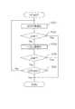
図3は、被検体の位置決め手順を示すフローチャートである。 FIG. 3 is a flowchart showing a procedure for positioning the subject.
治療台30の天板31上の被検体に対し、選択された2つの撮像系によるX線透視を実行し、フラットパネルディテクタ21a〜21dのうちの2つから画像情報を取得し、異なる2方向からのX線透視画像を得る(画像取得工程:ステップS1)。 X-ray fluoroscopy is performed on the subject on the
コンピュータ上の仮想空間にX線透視撮影のジオメトリを再現し、予め取得した3次元CT画像データに対して仮想的透視投影が実行される。CT画像データは、治療計画策定時にX線CT装置により取得し、図示を省略した患者DBに格納しておく。制御部40は、ネットワーク17を介して治療計画およびCT画像データを取得する。しかる後、DRR作成部42において、CT画像データへの仮想的透視投影により被検体の異なる2方向の2次元DRRが作成される(DRR作成工程:ステップS2)。 The geometry of X-ray fluoroscopy is reproduced in a virtual space on a computer, and virtual perspective projection is performed on previously acquired three-dimensional CT image data. The CT image data is acquired by an X-ray CT apparatus when formulating a treatment plan, and stored in a patient DB (not shown). The
X線透視撮影のジオメトリには、選択された2つの撮像系におけるX線管11a〜11dのいずれか2個、フラットパネルディテクタ21a〜21dのいずれか2個の位置および天板31の位置・姿勢が含まれる。これらの要素の機械的設置精度は、最終的な位置決め精度に影響を与えるため、定期的に設置位置の構成を行い、X線透視撮影のジオメトリに校正結果を反映している。 The geometry of the X-ray fluoroscopy includes the positions of any two of the
DRR作成時には、選択された撮像系におけるX線管11a〜11dのいずれかの焦点からフラットパネルディテクタ21a〜21dのいずれかへの投影線に沿って、CT画像データのボクセル値が積算(線積分)される(特許文献3、図12参照)。 At the time of DRR creation, the voxel values of the CT image data are integrated (line integration) along a projection line from any one of the
位置合わせ部43では、DRRとX線透視画像の一致を評価する評価関数が最大となるように、透視投影の回転および平行移動に関するパラメータの最適化が行われ、CT画像データとX線透視画像との位置合わせが実行される(位置合わせ工程:ステップS3)。ここで、評価関数としては、正規化相互情報量(NMI:Nomalized Mutual Information)、勾配差(GD:Gradient Difference)、ゼロ平均正規化相互相関(ZNCC:Nero−means Normalized Cross−Correlation)など、従来からマルチモダリティの画像位置合わせに用いられている評価関数を採用することができる。なお、NMI、GD、ZNCCを組み合わせて使用することで、DRRとX線画像の一致度の評価精度を向上させることもできる。 The
評価関数の計算は、画像中の被検体が写っている領域のみで行うことが好ましい。また、被検体内で動きのある臓器や関節など、CT画像データと再現性のない変形を伴う部位は、この評価関数の計算の対象外とすることが望ましい。 It is preferable that the calculation of the evaluation function is performed only in the region where the subject is present in the image. In addition, it is desirable that a part having a deformation that is not reproducible with CT image data, such as a moving organ or a joint in the subject, is excluded from the calculation of the evaluation function.
位置合わせ部43におけるパラメータの最適化等の計算が終了すると、移動量算出部44において、位置合わせの結果得られたX線透視画像とCT画像データとの位置ずれ量が天板移動量に換算され(移動量算出工程:ステップS4)、この移動量が、移動量算出部44から治療台30の天板移動機構32に送信される。しかる後、天板移動機構32の作用により天板31が移動する(天板移動工程:ステップS5)。このように、X線透視画像とCT画像データとの位置ずれ量だけ被検体が転置するように天板31を移動させることで、被検体は、放射線治療装置1から照射される治療ビームに対して治療計画通りの位置・角度に位置決めされる。なお、天板31を転置して被検体の位置決めを行った後には、再度X線透視を行って、X線透視画像とDRRとを表示部15に表示させ、それらの画像が一致しているか否かがユーザーによる目視確認により行われる。そして、放射線治療装置1のヘッド55から治療ビームが被検体の患部に向けて照射される。 When the calculation such as parameter optimization in the
位置合わせ部43でのパラメータの最適化について、さらに詳細に説明する。図4は、パラメータの最適化の手順を示すフローチャートである。 Optimization of the parameters in the
この実施形態では、治療台30に天板31を6軸移動させるものを採用していることから、評価関数は、天板31の移動軸に対応する回転3軸と平行移動3軸に関する6つの独立変数に依存する6次元関数である。したがって、位置合わせ部43における多次元最適化部45においては、放射線治療装置1の照射野に位置するターゲットアイソセンターを回転中心とし、評価関数の6次元最適化演算が実行される(多次元最適化工程:ステップS31)。なお、多次元最適化の次元は、例えば、治療台30が天板31を4軸移動させるものであれば、4次元となる。 In this embodiment, since the top 30 is moved by six axes to the treatment table 30, the evaluation function includes six rotation-related axes corresponding to the movement axes of the top 31 and three parallel movement three axes. It is a six-dimensional function depending on the independent variable. Therefore, in the
多次元最適化演算の手法として、BFGS公式による準ニュートン法を用いる。準ニュートン法では、評価関数をf(x)としたとき、6次元位置xを以下の式(1)に従って更新する。 The quasi-Newton method based on the BFGS formula is used as a multidimensional optimization calculation technique. In the quasi-Newton method, when the evaluation function is f (x), the six-dimensional position x is updated according to the following equation (1).

ここで、Hはヘッセ行列の逆行列の近似である。また、Hの近似式はいくつか提案されているが、以下の式(2)(3)で与えられるBFGS公式が最も計算効率が良い。 Here, H is an approximation of the inverse matrix of the Hessian matrix. Although several approximate expressions for H have been proposed, the BFGS formula given by the following expressions (2) and (3) has the highest calculation efficiency.
ここで、異なる2方向の評価関数の値をF1、F2としたとき、異なる2方向の評価関数の和F1+F2を最終的な評価関数の値とする。なお、異なる2方向のいずれか一方が、位置決めにおいてより重要な場合には、F1、F2を重み付け加算してもよい。 Here, assuming that the values of the evaluation functions in two different directions are F1 and F2, the sum F1 + F2 of the evaluation functions in the two different directions is the final evaluation function value. If one of the two different directions is more important in positioning, F1 and F2 may be weighted and added.
位置合わせ部43における1次元最適化部46では、選択された2つの撮影系における撮影方向に沿った1次元平行移動に関するパラメータが最適化される(1次元最適化工程:ステップS33)。1次元最適化部46における評価関数は、撮影方向に沿った1次元平行移動に関する1つの変数に依存する1次関数である。ここでの最適化では、Brent法や黄金分割法などを用いることができる。 The one-
最終的な評価関数値は、多次元最適化の場合と同様に、異なる2方向の評価関数値をそれぞれF1、F2としたとき、異なる2方向の評価関数値の和F1+F2を用いるが、値の大きな評価関数(F1またはF2のどちらか一方)のみを用いることが好ましい。すなわち、最適化の経路が評価関数の谷構造に沿っているときは、値の小さい評価関数は最適化への寄与が小さいため、位置ずれが撮影方向に沿っていない側の値の大きな目的関数のみで最適化を行うことで、計算の高速化が可能となる。 Assuming that the evaluation function values in two different directions are F1 and F2, respectively, as in the case of the multidimensional optimization, the final evaluation function value uses the sum F1 + F2 of the evaluation function values in the two different directions. It is preferable to use only a large evaluation function (either F1 or F2). In other words, when the optimization path is along the valley structure of the evaluation function, the evaluation function with a small value has a small contribution to the optimization, and therefore the objective function with a large value on the side where the displacement is not along the imaging direction. Performing the optimization only with the use of the above makes it possible to speed up the calculation.
多次元最適化と1次元最適化とは、評価関数の値が収束判定値に到達するまで(判定工程:ステップS32、ステップS34)、繰り返し実行される。また、多次元最適化の後の評価関数値の判定で収束していると判定できれば(ステップS32)、1次元最適化演算をスキップして最適化演算を終了する。なお、この実施形態では、多次元最適化と1次元最適化とで、異なる評価関数を用い、評価関数の値の収束判定値に異なる値を用いている。このように、それぞれに適した評価関数、収束判定値を用いることで、より適切にパラメータの最適化を行うことができる。 The multidimensional optimization and the one-dimensional optimization are repeatedly executed until the value of the evaluation function reaches the convergence determination value (determination process: step S32, step S34). If it is determined that the convergence has occurred in the evaluation function value after the multidimensional optimization (step S32), the one-dimensional optimization operation is skipped and the optimization operation ends. In this embodiment, different evaluation functions are used for the multidimensional optimization and the one-dimensional optimization, and different values are used for the convergence determination value of the evaluation function. As described above, by using the evaluation function and the convergence determination value suitable for each, the parameters can be more appropriately optimized.
さらに、所定の計算時間または所定の計算回数に達しても収束判定値に到達しない場合は、最適化の繰り返し計算を打ち切る(打ち切り判断工程:ステップS35)。このような、時間的な制限を設けることで、同じ姿勢で天板31上に固定される患者の負担や放射線治療装置1のスループットの低下が軽減される。なお、最適化においては、多次元最適化演算と1次元最適化演算とを繰り返し実行することから、これらの順序は逆であってもよい。 Furthermore, when the convergence determination value is not reached even after reaching the predetermined calculation time or the predetermined number of calculations, the repetition calculation of optimization is terminated (discontinuation determination step: step S35). By providing such a time limit, the burden on the patient fixed on the
図5は、この発明の1次元最適化演算を実行したときの評価関数の谷構造と画像の類似度の最適化の過程を模式的に示す説明図である。 FIG. 5 is an explanatory diagram schematically showing a process of optimizing the valley structure of the evaluation function and the similarity of the image when the one-dimensional optimization operation of the present invention is executed.
1次元最適化部46において、撮影方向に沿った1次元平行移動に関するパラメータを最適化したことで、最適化の経路は、従来のように谷構造を跨ぐようにジグザグに進む(図9参照)のではなく、図5に示すように、谷構造に沿って進行する。このため、最適化の序盤だけではなく、最適化の終盤まで撮影方向を考慮した最適化が可能となり、従来の被検体に対して傾斜角を持った異なる2方向からX線透視を行った場合にSIDが長くなることによる最適化演算の進行の停滞問題を解決している。これにより、効率よく最適化演算が行われ、全体の計算時間を従来よりも短くすることができ、かつ、位置決め精度も向上させることが可能となる。 The one-
図6は、他のパラメータの最適化の手順を示すフローチャートである。 FIG. 6 is a flowchart showing a procedure for optimizing other parameters.
図6に示すパラメータの最適化の手順は、図4に示す手順と同様に、多次元最適化(ステップS131)、評価関数値の収束判定(ステップS132)、1次元最適化(ステップS134)、評価関数値の収束判定(ステップS135)、最適化の繰り返し計算の打ち切り判定(ステップS136)を行うが、1次元最適化の前に、1次元最適化を実行するか否かを判定する工程(ステップS133)を設けている点において、図4を参照して先に説明した手順とは異なる。 The procedure for optimizing the parameters shown in FIG. 6 is, similarly to the procedure shown in FIG. 4, a multidimensional optimization (step S131), a convergence judgment of the evaluation function value (step S132), a one-dimensional optimization (step S134), A convergence determination of the evaluation function value (step S135) and a discontinuation determination of the repetitive calculation of the optimization (step S136) are performed. Before the one-dimensional optimization, a step of determining whether to execute the one-dimensional optimization ( The difference from the procedure described above with reference to FIG. 4 in that step S133) is provided.
1次元最適化は、1次元最適化の直前での異なる2方向の評価関数の値をそれぞれF1、F2としたとき、F1/F2の自然対数を表すLn(F1/F2)の絶対値が所定の値aより大きいときにのみ行うことが好ましい。すなわち、異なる2方向の評価関数の値が大きく異なっているときは、評価関数の谷構造(図5および図9参照)に落ち込んでいると判断できる。すなわち、異なる2方向の画像はほぼ左右対称(図8参照)であることから、谷構造に落ち込んだときは、F1、F2の両者の値の差が大きくなり、そうでないときは差が小さくなる。したがって、両者の差が大きいときのみ撮影方向に沿った1次元最適化を行う。このように。評価関数の値が谷構造に落ち込んだときにのみ1次元最適化を実行することで、さらに効率的に最適化を行うことができる。 In the one-dimensional optimization, when the values of the evaluation functions in two different directions immediately before the one-dimensional optimization are F1 and F2, respectively, the absolute value of Ln (F1 / F2) representing the natural logarithm of F1 / F2 is predetermined. Is preferably performed only when the value a is larger than the value a. In other words, when the values of the evaluation functions in the two different directions are significantly different, it can be determined that the evaluation function falls into the valley structure (see FIGS. 5 and 9). That is, since the images in the two different directions are almost symmetrical (see FIG. 8), the difference between the values of F1 and F2 becomes large when the image falls into the valley structure, and the difference becomes small otherwise. . Therefore, one-dimensional optimization along the shooting direction is performed only when the difference between the two is large. in this way. By executing the one-dimensional optimization only when the value of the evaluation function falls into the valley structure, the optimization can be performed more efficiently.
また、パラメータの最適化演算は、図4、図5を参照して説明した最適化手順に、多重解像度処理を組み合わせることにより、高速化することが可能である。この多重解像度処理は、X線透視画像とDRRをピラミッド構造の多重解像度画像とするダウンサンプリング法を利用するものであり、位置ずれが大きい最適化の初期段階では、X線透視画像をダウンサンプリングにより低解像度画像とし、低解像度で作成されたDRRとの一致度を評価する。そして、繰り返し計算により位置ずれが小さくなり、さらに高い位置決め精度が求められる最適化の最終段階では、高解像度画像により画像間の一致度を評価する。 The parameter optimization operation can be speeded up by combining the optimization procedure described with reference to FIGS. 4 and 5 with multi-resolution processing. This multi-resolution processing uses a down-sampling method in which the X-ray fluoroscopic image and the DRR are converted into a pyramid-structured multi-resolution image. In the initial stage of optimization in which the displacement is large, the X-ray fluoroscopic image is down-sampled. A low-resolution image is used, and the degree of coincidence with a DRR created at a low resolution is evaluated. In the final stage of optimization, in which positional deviation is reduced by repeated calculation and higher positioning accuracy is required, the degree of coincidence between images is evaluated using high-resolution images.
また、評価的関数値が谷構造に落ち込む頻度は高解像度ほど高い傾向にあるため、解像度ごとの多重解像度処理を行う際には、全ての解像度で多次元最適化と1次元最適化を繰り返し行うのではなく、解像度ごとに1次元最適化を行うか否かを切り替えてもよい。すなわち、撮影方向を考慮しなくても解空間での最適化の方向が好ましい解の探索方向から大きくはずれることがない低解像度側で1次元最適化を省略することで、さらに、最適化演算を高速化することが可能となる。なお、多重解像度画像処理を行うときには、各解像度で得られる精度に基づいて、解像度ごとに異なる収束判定値を用いることが好ましい。 Also, the frequency at which the evaluative function value falls into the valley structure tends to increase as the resolution increases, so that when performing multi-resolution processing for each resolution, multi-dimensional optimization and one-dimensional optimization are repeatedly performed at all resolutions. Instead, whether or not to perform one-dimensional optimization may be switched for each resolution. That is, by omitting the one-dimensional optimization on the low resolution side where the direction of optimization in the solution space does not largely deviate from the preferred solution search direction without considering the shooting direction, the optimization operation can be further performed. It is possible to increase the speed. When performing multi-resolution image processing, it is preferable to use a different convergence determination value for each resolution based on the accuracy obtained at each resolution.
上述した被検体の位置決めでは、位置合わせ部43におけるX線透視画像とCT画像データとの位置合わせの結果を、放射線治療装置1から治療ビームを照射する前の天板31の移動に利用しているが、必ずしも天板31を移動させる必要はない。例えば、治療中に位置ずれがないか確認するために、位置合わせの結果を利用してもよい。多次元最適化の次元は、例えば、治療台30が天板31を4軸移動させるものであれば、4次元となると説明したが、必ずしも多次元最適化の次元と天板31の移動軸とが一致している必要はない。例えば、天板31が4軸移動(3軸平行移動+鉛直軸回転)しかできないにもかかわらず、最適化のパラメータを6次元とすることができる。この場合、天板移動軸にない2軸の回転ができないが、操作者に2軸回転の位置ずれがある旨を警告表示することが可能である。警告を見た操作者は患者を手動で2軸回転するなどして患者姿勢を合わせることができる。 In the above-described positioning of the subject, the result of the positioning between the X-ray fluoroscopic image and the CT image data in the
1 放射線治療装置
10 X線管制御部
11 X線管
15 表示部
16 入力部
17 ネットワーク
21 フラットパネルディテクタ
30 治療台
31 天板
32 天板移動機構
40 制御部
41 画像取得部
42 DRR作成部
43 位置合わせ部
44 移動量算出部
45 多次元最適化部
46 1次元最適化部
Claims (10)
Translated fromJapanese放射線照射部と放射線検出器を有し、被検体に対して傾斜角を持った異なる2方向の撮像系により前記被検体の異なる2方向の2次元放射線画像を取得する画像取得部と、
仮想空間に前記撮像系の幾何学的配置を再現し、予め収集されたCT画像データに仮想的に透視投影を行うことにより、前記被検体の異なる2方向のDRRを作成するDRR作成部と、
異なる2方向の前記放射線画像と前記DRRとの一致度を評価する評価関数が最大となるように、前記CT画像データと前記放射線画像とを位置合わせする位置合わせ部と、
を備え、
前記位置合わせ部は、
前記CT画像データへの前記透視投影における、前記治療台の移動軸に対応した回転および平行移動に関するパラメータを最適化する多次元最適化部と、
前記多次元最適化部によって最適化を行った後に前記撮像系の撮影方向に沿った1次元平行移動に関するパラメータを最適化する1次元最適化部と、
を備えること、を特徴とする位置決め装置。When performing radiotherapy to irradiate a treatment beam toward the affected part of the subject on the treatment table, a positioning device for positioning the subject,
An image acquisition unit having a radiation irradiation unit and a radiation detector, and acquiring a two-dimensional radiation image of the subject in two different directions by an imaging system of two different directions having an inclination angle with respect to the subject;
A DRR creation unit that creates a DRR in two different directions of the subject by reproducing the geometric arrangement of the imaging system in a virtual space and virtually performing perspective projection on CT image data collected in advance;
An alignment unit that aligns the CT image data and the radiation image so that an evaluation function for evaluating the degree of coincidence between the radiation image and the DRR in two different directions is maximized.
With
The positioning unit,
In the perspective projection to the CT image data, a multidimensional optimization unit that optimizes parameters related to rotation and translation corresponding to the movement axis of the treatment table,
A one-dimensional optimizing unit that optimizes a parameter related to one-dimensional parallel movement along a shooting direction of the imaging system after performing optimization by the multidimensional optimizing unit;
And a positioning device.
前記1次元最適化部は、前記多次元最適化部における最適化により取得された前記評価関数の値に基づいて、1次元最適化を実行するか否かを決定する位置決め装置。The positioning device according to claim 1,
The positioning device, wherein the one-dimensional optimization unit determines whether to perform one-dimensional optimization based on a value of the evaluation function obtained by the optimization in the multidimensional optimization unit.
前記位置合わせ部は、前記多次元最適化部と前記1次元最適化部とで、異なる評価関数を用いる位置決め装置。In the positioning device according to claim 1 or 2,
The positioning device, wherein the positioning unit uses different evaluation functions for the multidimensional optimization unit and the one-dimensional optimization unit.
前記位置合わせ部は、前記多次元最適化部と前記1次元最適化部とで、最適化の収束を判定する収束判定値に異なる値を用いる位置決め装置。In the positioning device according to any one of claims 1 to 3,
The positioning device, wherein the positioning unit uses different values for convergence determination values for determining convergence of optimization between the multidimensional optimization unit and the one-dimensional optimization unit.
前記位置合わせ部は、異なる2方向の前記放射線画像と前記DRRとを解像度ごとに異なる評価関数を用いて最適化する多重解像度処理を実行する位置決め装置。In the positioning device according to any one of claims 1 to 4,
The positioning device, wherein the positioning unit executes a multi-resolution process for optimizing the radiation image and the DRR in two different directions using different evaluation functions for each resolution.
前記位置合わせ部は、前記1次元最適化部における1次元最適化を解像度ごとに実行するか否かを判断する位置決め装置。The positioning device according to claim 5,
The positioning device, wherein the positioning unit determines whether the one-dimensional optimization in the one-dimensional optimization unit is performed for each resolution.
前記1次元最適化部は、前記多次元最適化部によって最適化を行った後、前記多次元最適化部によって最適化が収束しなかった場合に前記撮像系の撮影方向に沿った1次元平行移動に関するパラメータを最適化する位置決め装置。The positioning device according to claim 1,
The one-dimensional optimization unit, after performing optimization by the multi-dimensional optimization unit, when the optimization does not converge by the multi-dimensional optimization unit, the one-dimensional parallel unit along the imaging direction of the imaging system. Positioning device that optimizes parameters related to movement.
放射線照射部と放射線検出器を有する撮像系により前記被検体の異なる2方向の2次元放射線画像を取得する画像取得部と、
仮想空間に前記撮像系の幾何学的配置を再現し、予め収集されたCT画像データに仮想的に透視投影を行うことにより、前記被検体の異なる2方向のDRRを作成するDRR作成部と、
異なる2方向の前記放射線画像と前記DRRとの一致度を評価する評価関数が最大となるように、前記CT画像データと前記放射線画像とを位置合わせする位置合わせ部と、
を備え、
前記位置合わせ部は、
前記CT画像データへの前記透視投影における、前記治療台の移動軸に対応した回転および平行移動に関するパラメータを最適化する多次元最適化部と、
前記撮像系の撮影方向に沿った1次元平行移動に関するパラメータを最適化する1次元最適化部と、を備え、
前記1次元最適化部は、前記多次元最適化部における最適化により取得された前記評価関数の値に基づいて、1次元最適化を実行するか否かを決定すること、を特徴とする位置決め装置。When performing radiotherapy to irradiate a treatment beam toward the affected part of the subject on the treatment table, a positioning device for positioning the subject,
An image acquisition unit that acquires two-dimensional radiation images of the subject in two different directions by an imaging system having a radiation irradiation unit and a radiation detector;
A DRR creation unit that creates a DRR in two different directions of the subject by reproducing the geometric arrangement of the imaging system in a virtual space and virtually performing perspective projection on CT image data collected in advance;
An alignment unit that aligns the CT image data and the radiation image so that an evaluation function for evaluating the degree of coincidence between the radiation image and the DRR in two different directions is maximized.
With
The positioning unit,
In the perspective projection to the CT image data, a multidimensional optimization unit that optimizes parameters related to rotation and translation corresponding to the movement axis of the treatment table,
A one-dimensional optimization unit that optimizes a parameter related to one-dimensional translation in the imaging direction of the imaging system,
The one-dimensional optimization unit determines whether to perform one-dimensional optimization based on the value of the evaluation function obtained by the optimization in the multidimensional optimization unit. apparatus.
放射線照射部と放射線検出器を有する撮像系により前記被検体の異なる2方向の2次元放射線画像を取得する画像取得部と、
仮想空間に前記撮像系の幾何学的配置を再現し、予め収集されたCT画像データに仮想的に透視投影を行うことにより、前記被検体の異なる2方向のDRRを作成するDRR作成部と、
異なる2方向の前記放射線画像と前記DRRとの一致度を評価する評価関数が最大となるように、前記CT画像データと前記放射線画像とを位置合わせする位置合わせ部と、
を備え、
前記位置合わせ部は、
前記CT画像データへの前記透視投影における、前記治療台の移動軸に対応した回転および平行移動に関するパラメータを最適化する多次元最適化部と、
前記撮像系の撮影方向に沿った1次元平行移動に関するパラメータを最適化する1次元最適化部と、を備え、
前記位置合わせ部は、異なる2方向の前記放射線画像と前記DRRとを解像度ごとに異なる評価関数を用いて最適化する多重解像度処理を実行し、
前記位置合わせ部は、前記1次元最適化部における1次元最適化を解像度ごとに実行するか否かを判断することを特徴とする位置決め装置。When performing radiotherapy to irradiate a treatment beam toward the affected part of the subject on the treatment table, a positioning device for positioning the subject,
An image acquisition unit that acquires two-dimensional radiation images of the subject in two different directions by an imaging system having a radiation irradiation unit and a radiation detector;
A DRR creation unit that creates a DRR in two different directions of the subject by reproducing the geometric arrangement of the imaging system in a virtual space and virtually performing perspective projection on CT image data collected in advance;
An alignment unit that aligns the CT image data and the radiation image so that an evaluation function for evaluating the degree of coincidence between the radiation image and the DRR in two different directions is maximized.
With
The positioning unit,
In the perspective projection to the CT image data, a multidimensional optimization unit that optimizes parameters related to rotation and translation corresponding to the movement axis of the treatment table,
A one-dimensional optimization unit that optimizes a parameter related to one-dimensional translation in the imaging direction of the imaging system,
The positioning unit executes a multi-resolution process of optimizing the radiation image and the DRR in two different directions using different evaluation functions for each resolution.
The positioning device according to claim 1, wherein the positioning unit determines whether or not to execute the one-dimensional optimization in the one-dimensional optimization unit for each resolution.
前記画像取得部が、放射線照射部と放射線検出器を有し、被検体に対して傾斜角を持った異なる2方向の撮像系により前記被検体の異なる2方向の2次元放射線画像を取得する画像取得工程と、
前記DRR作成部が、仮想空間に前記撮像系の幾何学的配置を再現し、予め収集されたCT画像データに仮想的に透視投影を行うことにより、前記被検体の異なる2方向のDRRを作成するDRR作成工程と、
前記位置合わせ部が、異なる2方向の前記放射線画像と前記DRRとの一致度を評価する評価関数が最大となるように、前記CT画像データと前記放射線画像とを位置合わせする位置合わせ工程と、
を備え、
前記位置合わせ工程は、
前記多次元最適化部が、前記CT画像データへの前記透視投影における、前記治療台の移動軸に対応した回転および平行移動に関するパラメータを最適化する多次元最適化工程と、
前記1次元最適化部が、前記多次元最適化工程によって最適化が収束しなかった場合に前記撮像系の撮影方向に沿った1次元平行移動に関するパラメータを最適化する1次元最適化工程と、
を含むこと、を特徴とする位置決め装置の作動方法。An operation method of the positioning apparatus according to any one of claims 1 to 9, wherein when performing radiation therapy for irradiating a treatment beam toward an affected part of the subject on the treatment table, the subject is positioned.
The image acquisition unit includes a radiation irradiation unit and a radiation detector, and acquires two-dimensional radiographic images of the subject in two different directions using two different imaging systems having tilt angles with respect to the subject. The acquisition process,
The DRR creation unit creates DRRs of the subject in two different directions by reproducing the geometric arrangement of the imaging system in a virtual space and virtually performing perspective projection on CT image dataacquired in advance. DRR creation process to
Said alignment unit, so that an evaluation function for evaluating the degree of coincidence between the two different directions of the radiation image said DRR is maximized, and the alignment step for aligning the radiation image and the CT image data,
With
The positioning step includes:
The multidimensional optimization unit, in the perspective projection to the CT image data, a multidimensional optimization step of optimizing parameters related to rotation and translation corresponding to the movement axis of the treatment table;
A one-dimensional optimization step inwhich the one-dimensional optimization unit optimizes parameters relating to one-dimensional translation in the imaging direction of the imaging system when the optimization does not converge in the multidimensional optimization step;
A method of operating a positioning device, comprising:
Priority Applications (3)
| Application Number | Priority Date | Filing Date | Title |
|---|---|---|---|
| JP2016079445AJP6668902B2 (en) | 2016-04-12 | 2016-04-12 | Positioning device and method of operating positioning device |
| US15/473,803US10722733B2 (en) | 2016-04-12 | 2017-03-30 | Positioning apparatus and method of positioning |
| CN201710209209.2ACN107281652B (en) | 2016-04-12 | 2017-03-31 | Positioning device |
Applications Claiming Priority (1)
| Application Number | Priority Date | Filing Date | Title |
|---|---|---|---|
| JP2016079445AJP6668902B2 (en) | 2016-04-12 | 2016-04-12 | Positioning device and method of operating positioning device |
Publications (2)
| Publication Number | Publication Date |
|---|---|
| JP2017189285A JP2017189285A (en) | 2017-10-19 |
| JP6668902B2true JP6668902B2 (en) | 2020-03-18 |
Family
ID=60000047
Family Applications (1)
| Application Number | Title | Priority Date | Filing Date |
|---|---|---|---|
| JP2016079445AActiveJP6668902B2 (en) | 2016-04-12 | 2016-04-12 | Positioning device and method of operating positioning device |
Country Status (3)
| Country | Link |
|---|---|
| US (1) | US10722733B2 (en) |
| JP (1) | JP6668902B2 (en) |
| CN (1) | CN107281652B (en) |
Cited By (2)
| Publication number | Priority date | Publication date | Assignee | Title |
|---|---|---|---|---|
| WO2023079811A1 (en) | 2021-11-08 | 2023-05-11 | 株式会社日立製作所 | Positioning device, radiation therapy device, and positioning method |
| WO2023157616A1 (en) | 2022-02-18 | 2023-08-24 | 株式会社日立製作所 | Positioning device, radiation therapy device, and positioning method |
Families Citing this family (21)
| Publication number | Priority date | Publication date | Assignee | Title |
|---|---|---|---|---|
| GB2536650A (en) | 2015-03-24 | 2016-09-28 | Augmedics Ltd | Method and system for combining video-based and optic-based augmented reality in a near eye display |
| JP6740060B2 (en)* | 2016-09-01 | 2020-08-12 | キヤノンメディカルシステムズ株式会社 | X-ray CT system |
| CN108651614A (en)* | 2018-03-08 | 2018-10-16 | 潘立敏 | A kind of agricultural with cereal teds equipment automatically |
| US11980507B2 (en) | 2018-05-02 | 2024-05-14 | Augmedics Ltd. | Registration of a fiducial marker for an augmented reality system |
| JP7279336B2 (en)* | 2018-10-26 | 2023-05-23 | 株式会社島津製作所 | X-ray equipment |
| US11766296B2 (en) | 2018-11-26 | 2023-09-26 | Augmedics Ltd. | Tracking system for image-guided surgery |
| JP7287828B2 (en)* | 2019-04-26 | 2023-06-06 | 株式会社日立製作所 | Patient positioning system, method and program |
| JP7311109B2 (en) | 2019-05-14 | 2023-07-19 | 東芝エネルギーシステムズ株式会社 | medical image processing device, medical image processing program, medical device, and treatment system |
| US11980506B2 (en) | 2019-07-29 | 2024-05-14 | Augmedics Ltd. | Fiducial marker |
| US12178666B2 (en) | 2019-07-29 | 2024-12-31 | Augmedics Ltd. | Fiducial marker |
| US11382712B2 (en) | 2019-12-22 | 2022-07-12 | Augmedics Ltd. | Mirroring in image guided surgery |
| US11389252B2 (en) | 2020-06-15 | 2022-07-19 | Augmedics Ltd. | Rotating marker for image guided surgery |
| CN115485017A (en)* | 2020-08-12 | 2022-12-16 | 西安大医集团股份有限公司 | Image display control method, image display control device, electronic device, and computer storage medium |
| US12239385B2 (en) | 2020-09-09 | 2025-03-04 | Augmedics Ltd. | Universal tool adapter |
| KR102689375B1 (en)* | 2021-07-07 | 2024-07-30 | 한국과학기술원 | Skeleton estimate apparatus using multiple x-ray views and method thereof |
| US11896445B2 (en) | 2021-07-07 | 2024-02-13 | Augmedics Ltd. | Iliac pin and adapter |
| US12150821B2 (en) | 2021-07-29 | 2024-11-26 | Augmedics Ltd. | Rotating marker and adapter for image-guided surgery |
| WO2023021448A1 (en) | 2021-08-18 | 2023-02-23 | Augmedics Ltd. | Augmented-reality surgical system using depth sensing |
| EP4511809A1 (en) | 2022-04-21 | 2025-02-26 | Augmedics Ltd. | Systems and methods for medical image visualization |
| IL319523A (en) | 2022-09-13 | 2025-05-01 | Augmedics Ltd | Augmented reality eyewear for image-guided medical intervention |
| CN119446391A (en)* | 2025-01-10 | 2025-02-14 | 吉林大学 | Patient rehabilitation training data collection method and system based on visual recognition |
Family Cites Families (108)
| Publication number | Priority date | Publication date | Assignee | Title |
|---|---|---|---|---|
| JPH09154961A (en)* | 1995-12-07 | 1997-06-17 | Toshiba Medical Eng Co Ltd | Radiation treatment planning method |
| WO1998002091A1 (en)* | 1996-07-11 | 1998-01-22 | The Board Of Trustees Of The Leland Stanford Junior University | High-speed inter-modality image registration via iterative feature matching |
| US5825845A (en)* | 1996-10-28 | 1998-10-20 | Loma Linda University Medical Center | Proton beam digital imaging system |
| JP3896188B2 (en)* | 1997-06-13 | 2007-03-22 | 株式会社日立製作所 | Image processing device for radiation therapy planning |
| DE19953177A1 (en)* | 1999-11-04 | 2001-06-21 | Brainlab Ag | Method to position patient exactly for radiation therapy or surgery; involves comparing positions in landmarks in X-ray image and reconstructed image date, to determine positioning errors |
| US6714810B2 (en)* | 2000-09-07 | 2004-03-30 | Cbyon, Inc. | Fluoroscopic registration system and method |
| US6674833B2 (en)* | 2000-09-07 | 2004-01-06 | Cbyon, Inc. | Virtual fluoroscopic system and method |
| US6907281B2 (en)* | 2000-09-07 | 2005-06-14 | Ge Medical Systems | Fast mapping of volumetric density data onto a two-dimensional screen |
| DE10051370A1 (en)* | 2000-10-17 | 2002-05-02 | Brainlab Ag | Method and appliance for exact positioning of patient for radiation therapy and radio surgery with which only one camera is used to determine and compensate for positional error |
| JP2006501948A (en)* | 2002-10-07 | 2006-01-19 | ノモス・コーポレーシヨン | Method and apparatus for target position verification |
| US7260426B2 (en)* | 2002-11-12 | 2007-08-21 | Accuray Incorporated | Method and apparatus for tracking an internal target region without an implanted fiducial |
| US6889695B2 (en)* | 2003-01-08 | 2005-05-10 | Cyberheart, Inc. | Method for non-invasive heart treatment |
| DE10322738A1 (en)* | 2003-05-20 | 2004-12-16 | Siemens Ag | Markerless automatic 2D C scan and preoperative 3D image fusion procedure for medical instrument use uses image based registration matrix generation |
| CA2535121C (en)* | 2003-08-12 | 2021-03-23 | Loma Linda University Medical Center | Patient positioning system for radiation therapy system |
| US7187792B2 (en)* | 2003-08-29 | 2007-03-06 | Accuray, Inc. | Apparatus and method for determining measure of similarity between images |
| US7315636B2 (en)* | 2003-09-18 | 2008-01-01 | Accuray, Inc. | Generation of reconstructed images |
| US7072435B2 (en)* | 2004-01-28 | 2006-07-04 | Ge Medical Systems Global Technology Company, Llc | Methods and apparatus for anomaly detection |
| US7653226B2 (en)* | 2004-04-21 | 2010-01-26 | Siemens Medical Solutions Usa, Inc. | Flexible generation of digitally reconstructed radiographs |
| US7327865B2 (en)* | 2004-06-30 | 2008-02-05 | Accuray, Inc. | Fiducial-less tracking with non-rigid image registration |
| US7426318B2 (en)* | 2004-06-30 | 2008-09-16 | Accuray, Inc. | Motion field generation for non-rigid image registration |
| US7522779B2 (en)* | 2004-06-30 | 2009-04-21 | Accuray, Inc. | Image enhancement method and system for fiducial-less tracking of treatment targets |
| US7231076B2 (en)* | 2004-06-30 | 2007-06-12 | Accuray, Inc. | ROI selection in image registration |
| US7366278B2 (en)* | 2004-06-30 | 2008-04-29 | Accuray, Inc. | DRR generation using a non-linear attenuation model |
| US8989349B2 (en)* | 2004-09-30 | 2015-03-24 | Accuray, Inc. | Dynamic tracking of moving targets |
| US7453983B2 (en)* | 2005-01-20 | 2008-11-18 | Carestream Health, Inc. | Radiation therapy method with target detection |
| US8077936B2 (en)* | 2005-06-02 | 2011-12-13 | Accuray Incorporated | Treatment planning software and corresponding user interface |
| US7349522B2 (en)* | 2005-06-22 | 2008-03-25 | Board Of Trustees Of The University Of Arkansas | Dynamic radiation therapy simulation system |
| US7330578B2 (en)* | 2005-06-23 | 2008-02-12 | Accuray Inc. | DRR generation and enhancement using a dedicated graphics device |
| US7302033B2 (en)* | 2005-06-29 | 2007-11-27 | Accuray Incorporated | Imaging geometry for image-guided radiosurgery |
| US7713205B2 (en)* | 2005-06-29 | 2010-05-11 | Accuray Incorporated | Dynamic tracking of soft tissue targets with ultrasound images, without using fiducial markers |
| US7831073B2 (en)* | 2005-06-29 | 2010-11-09 | Accuray Incorporated | Precision registration of X-ray images to cone-beam CT scan for image-guided radiation treatment |
| US7835500B2 (en)* | 2005-11-16 | 2010-11-16 | Accuray Incorporated | Multi-phase registration of 2-D X-ray images to 3-D volume studies |
| US7684647B2 (en)* | 2005-11-16 | 2010-03-23 | Accuray Incorporated | Rigid body tracking for radiosurgery |
| US7453984B2 (en)* | 2006-01-19 | 2008-11-18 | Carestream Health, Inc. | Real-time target confirmation for radiation therapy |
| US20070189455A1 (en)* | 2006-02-14 | 2007-08-16 | Accuray Incorporated | Adaptive x-ray control |
| JP4310319B2 (en)* | 2006-03-10 | 2009-08-05 | 三菱重工業株式会社 | Radiotherapy apparatus control apparatus and radiation irradiation method |
| US7532705B2 (en)* | 2006-04-10 | 2009-05-12 | Duke University | Systems and methods for localizing a target for radiotherapy based on digital tomosynthesis |
| JP4126318B2 (en)* | 2006-06-23 | 2008-07-30 | 三菱重工業株式会社 | Radiotherapy apparatus control apparatus and radiotherapy apparatus control method |
| US7620144B2 (en)* | 2006-06-28 | 2009-11-17 | Accuray Incorporated | Parallel stereovision geometry in image-guided radiosurgery |
| US7570738B2 (en)* | 2006-08-04 | 2009-08-04 | Siemens Medical Solutions Usa, Inc. | Four-dimensional (4D) image verification in respiratory gated radiation therapy |
| US7894649B2 (en)* | 2006-11-02 | 2011-02-22 | Accuray Incorporated | Target tracking using direct target registration |
| US8831706B2 (en)* | 2006-11-03 | 2014-09-09 | Accuray Incorporated | Fiducial-less tracking of a volume of interest |
| CN100551465C (en)* | 2006-12-25 | 2009-10-21 | 深圳市海博科技有限公司 | A method for automatic positioning of patient's target area in radiotherapy |
| US8417318B2 (en)* | 2007-02-22 | 2013-04-09 | Accuray Incorporated | Calibrating tracking systems to remove position-dependent bias |
| US7889902B2 (en)* | 2007-06-25 | 2011-02-15 | Accuray Incorporated | High quality volume rendering with graphics processing unit |
| US7623623B2 (en)* | 2007-06-29 | 2009-11-24 | Accuray Incorporated | Non-collocated imaging and treatment in image-guided radiation treatment systems |
| US9427201B2 (en)* | 2007-06-30 | 2016-08-30 | Accuray Incorporated | Non-invasive method for using 2D angiographic images for radiosurgical target definition |
| US7806589B2 (en)* | 2007-09-26 | 2010-10-05 | University Of Pittsburgh | Bi-plane X-ray imaging system |
| EP2070478B1 (en)* | 2007-12-13 | 2011-11-23 | BrainLAB AG | Detection of the position of a moving object and treatment method |
| US8086004B2 (en)* | 2008-01-15 | 2011-12-27 | Accuray Incorporated | Use of a single X-ray image for quality assurance of tracking |
| US8295435B2 (en)* | 2008-01-16 | 2012-10-23 | Accuray Incorporated | Cardiac target tracking |
| JP5253052B2 (en) | 2008-09-05 | 2013-07-31 | 三菱電機株式会社 | Patient positioning apparatus and patient positioning method in radiotherapy |
| WO2010030397A1 (en)* | 2008-09-12 | 2010-03-18 | Accuray Incorporated | Controlling x-ray imaging based on target motion |
| US8457372B2 (en)* | 2008-09-30 | 2013-06-04 | Accuray Incorporated | Subtraction of a segmented anatomical feature from an acquired image |
| US8525833B2 (en)* | 2008-10-13 | 2013-09-03 | George Papaioannou | Dynamic biplane roentgen stereophotogrammetric analysis |
| WO2010059349A1 (en)* | 2008-11-21 | 2010-05-27 | Cyberheart, Inc. | Test object for the validation of tracking in the presence of motion |
| US8515004B2 (en)* | 2009-01-16 | 2013-08-20 | Varian Medical Systems, Inc. | Real-time motion tracking using tomosynthesis |
| US7831013B2 (en)* | 2009-01-16 | 2010-11-09 | Varian Medical Systems, Inc. | Real-time motion tracking using tomosynthesis |
| JP5286145B2 (en) | 2009-04-16 | 2013-09-11 | 株式会社日立製作所 | Bed positioning method |
| EP2246096B1 (en)* | 2009-04-29 | 2016-11-09 | Brainlab AG | Method and device for determining preferred alignments of a radiation treatment source |
| WO2011061827A1 (en)* | 2009-11-18 | 2011-05-26 | 三菱重工業株式会社 | Radiation therapy apparatus control method and radiation therapy apparatus control device |
| DE102009057066B4 (en)* | 2009-12-04 | 2021-09-30 | Siemens Healthcare Gmbh | Radiation therapy device with an imaging device and a method for generating an image |
| US9687200B2 (en)* | 2010-06-08 | 2017-06-27 | Accuray Incorporated | Radiation treatment delivery system with translatable ring gantry |
| US8934605B2 (en)* | 2010-02-24 | 2015-01-13 | Accuray Incorporated | Gantry image guided radiotherapy system and related treatment delivery methods |
| US8693634B2 (en)* | 2010-03-19 | 2014-04-08 | Hologic Inc | System and method for generating enhanced density distribution in a three dimensional model of a structure for use in skeletal assessment using a limited number of two-dimensional views |
| WO2011156526A2 (en)* | 2010-06-08 | 2011-12-15 | Accuray, Inc. | Imaging methods and target tracking for image-guided radiation treatment |
| WO2012019162A1 (en)* | 2010-08-06 | 2012-02-09 | Accuray, Inc. | Systems and methods for real-time tumor tracking during radiation treatment using ultrasound imaging |
| US8989846B2 (en)* | 2010-08-08 | 2015-03-24 | Accuray Incorporated | Radiation treatment delivery system with outwardly movable radiation treatment head extending from ring gantry |
| US8315356B2 (en)* | 2010-09-17 | 2012-11-20 | Accuray Incorporated | Image alignment |
| US8824630B2 (en)* | 2010-10-29 | 2014-09-02 | Accuray Incorporated | Method and apparatus for treating a target's partial motion range |
| US8849633B2 (en)* | 2010-10-29 | 2014-09-30 | Accuray Incorporated | Method and apparatus for selecting a tracking method to use in image guided treatment |
| US8536547B2 (en)* | 2011-01-20 | 2013-09-17 | Accuray Incorporated | Ring gantry radiation treatment delivery system with dynamically controllable inward extension of treatment head |
| JP5611091B2 (en)* | 2011-03-18 | 2014-10-22 | 三菱重工業株式会社 | Radiotherapy apparatus control apparatus, processing method thereof, and program |
| JP5575022B2 (en)* | 2011-03-18 | 2014-08-20 | 三菱重工業株式会社 | Radiotherapy apparatus control apparatus, processing method thereof, and program |
| CN102222331B (en)* | 2011-05-16 | 2013-09-25 | 付东山 | Dual-flat panel-based two-dimensional to three-dimensional medical image registering method and system |
| US9415240B2 (en)* | 2011-10-21 | 2016-08-16 | Accuray Incorporated | Apparatus for generating multi-energy x-ray images and methods of using the same |
| JP2013099431A (en)* | 2011-11-08 | 2013-05-23 | Natl Inst Of Radiological Sciences | Automatic positioning device and method for patient in radiotherapy, and program for automatic positioning for patient |
| US8861672B2 (en)* | 2011-11-16 | 2014-10-14 | Siemens Medical Solutions Usa, Inc. | Patient positioning system |
| WO2013166299A1 (en)* | 2012-05-03 | 2013-11-07 | University Of Pittsburgh - Of The Commonwealth System Of Higher Education | Intelligent algorithms for tracking three-dimensional skeletal movement from radiographic image sequences |
| CN104602626B (en)* | 2012-08-28 | 2018-03-02 | 皇家飞利浦有限公司 | Interventional guidance system with integrated tracking setup |
| JP6207819B2 (en)* | 2012-09-20 | 2017-10-04 | 東芝メディカルシステムズ株式会社 | Image processing apparatus, X-ray diagnostic apparatus and program |
| US9672640B2 (en)* | 2013-01-24 | 2017-06-06 | Varian Medical Systems International Ag | Method for interactive manual matching and real-time projection calculation in imaging |
| US10092251B2 (en)* | 2013-03-15 | 2018-10-09 | Varian Medical Systems, Inc. | Prospective evaluation of tumor visibility for IGRT using templates generated from planning CT and contours |
| WO2014155556A1 (en) | 2013-03-27 | 2014-10-02 | 株式会社島津製作所 | Fluoroscopic device |
| US9861834B2 (en)* | 2013-05-02 | 2018-01-09 | The Board Of Trustees Of The Leland Stanford Junior University | Station parameter optimized radiation therapy (SPORT): a novel scheme for treatment planning and delivery in radiation therapy |
| JP6226621B2 (en)* | 2013-08-06 | 2017-11-08 | 株式会社東芝 | Medical image processing apparatus, medical image processing method, and medical image processing system |
| JP6165591B2 (en)* | 2013-10-31 | 2017-07-19 | 株式会社東芝 | Image processing apparatus, treatment system, and image processing method |
| JP6509906B2 (en)* | 2014-01-06 | 2019-05-08 | ボディ・ビジョン・メディカル・リミテッドBody Vision Medical Ltd. | Method of operating a medical device |
| US9230322B2 (en)* | 2014-04-04 | 2016-01-05 | Kabushiki Kaisha Toshiba | Image processor, treatment system, and image processing method |
| US9949709B2 (en)* | 2014-06-23 | 2018-04-24 | University Of Maryland, Baltimore | Techniques for suppression of motion artifacts in medical imaging |
| US9616251B2 (en)* | 2014-07-25 | 2017-04-11 | Varian Medical Systems, Inc. | Imaging based calibration systems, devices, and methods |
| JP6351011B2 (en)* | 2014-09-18 | 2018-07-04 | 株式会社島津製作所 | Positioning device and method of operating positioning device |
| JP6467654B2 (en)* | 2014-11-19 | 2019-02-13 | 東芝エネルギーシステムズ株式会社 | Medical image processing apparatus, method, program, and radiotherapy apparatus |
| JP6437286B2 (en)* | 2014-11-26 | 2018-12-12 | 株式会社東芝 | Image processing apparatus, image processing program, image processing method, and treatment system |
| JP2016116659A (en)* | 2014-12-19 | 2016-06-30 | 株式会社東芝 | Medical image processing device, treatment system, medical image processing method, and medical image processing program |
| EP3034003B1 (en)* | 2014-12-19 | 2017-11-08 | Ion Beam Applications S.A. | Method and imaging system for determining a reference radiograph for a later use in radiation therapy |
| US10413752B2 (en)* | 2015-02-09 | 2019-09-17 | Brainlab Ag | X-ray patient position monitoring |
| US9886760B2 (en)* | 2015-03-05 | 2018-02-06 | Broncus Medical Inc. | GPU-based system for performing 2D-3D deformable registration of a body organ using multiple 2D fluoroscopic views |
| WO2017000988A1 (en)* | 2015-06-30 | 2017-01-05 | Brainlab Ag | Medical image fusion with reduced search space |
| JP6565080B2 (en)* | 2015-08-11 | 2019-08-28 | 東芝エネルギーシステムズ株式会社 | Radiotherapy apparatus, operating method thereof, and program |
| US10631778B2 (en)* | 2015-10-01 | 2020-04-28 | Varian Medical Systems International Ag | Patient setup using respiratory gated and time resolved image data |
| US10083511B2 (en)* | 2015-10-30 | 2018-09-25 | Siemens Healthcare Gmbh | Angiographic roadmapping mask |
| US10065049B2 (en)* | 2016-01-25 | 2018-09-04 | Accuray Incorporated | Presenting a sequence of images associated with a motion model |
| US9990711B2 (en)* | 2016-01-25 | 2018-06-05 | Accuray Incorporated | Manipulation of a respiratory model via adjustment of parameters associated with model images |
| JP6533991B2 (en)* | 2016-02-16 | 2019-06-26 | 東芝エネルギーシステムズ株式会社 | MEDICAL IMAGE PROCESSING APPARATUS, METHOD, PROGRAM, AND RADIATION THERAPY APPARATUS |
| US10478148B2 (en)* | 2016-02-19 | 2019-11-19 | The Johns Hopkins University | Self-calibrating projection geometry for volumetric image reconstruction |
| US10272265B2 (en)* | 2016-04-01 | 2019-04-30 | Varian Medical Systems International Ag | Collision avoidance for radiation therapy |
| US10434335B2 (en) | 2017-03-30 | 2019-10-08 | Shimadzu Corporation | Positioning apparatus and method of positioning by generation of DRR image from X-ray CT image data |
- 2016
- 2016-04-12JPJP2016079445Apatent/JP6668902B2/enactiveActive
- 2017
- 2017-03-30USUS15/473,803patent/US10722733B2/enactiveActive
- 2017-03-31CNCN201710209209.2Apatent/CN107281652B/ennot_activeExpired - Fee Related
Cited By (2)
| Publication number | Priority date | Publication date | Assignee | Title |
|---|---|---|---|---|
| WO2023079811A1 (en) | 2021-11-08 | 2023-05-11 | 株式会社日立製作所 | Positioning device, radiation therapy device, and positioning method |
| WO2023157616A1 (en) | 2022-02-18 | 2023-08-24 | 株式会社日立製作所 | Positioning device, radiation therapy device, and positioning method |
Also Published As
| Publication number | Publication date |
|---|---|
| US20170291042A1 (en) | 2017-10-12 |
| CN107281652B (en) | 2019-12-13 |
| US10722733B2 (en) | 2020-07-28 |
| CN107281652A (en) | 2017-10-24 |
| JP2017189285A (en) | 2017-10-19 |
Similar Documents
| Publication | Publication Date | Title |
|---|---|---|
| JP6668902B2 (en) | Positioning device and method of operating positioning device | |
| JP5606065B2 (en) | Parallel stereoscopic geometry in image-guided radiosurgery | |
| EP3161785B1 (en) | System and method for image composition | |
| US20160278724A1 (en) | Robotic multi-mode radiological scanning system and method | |
| US12156756B2 (en) | Field of view matching for mobile 3D imaging | |
| US11045152B2 (en) | X-ray tomography apparatus and X-ray tomography method | |
| US12364877B2 (en) | Medical image processing device, storage medium, medical device, and treatment system | |
| EP4003176B1 (en) | User interface for x-ray tube-detector alignment | |
| JP2014212820A (en) | Radiotherapy system | |
| JP2017189526A (en) | Information processing apparatus and radiation therapy system | |
| JP7444387B2 (en) | Medical image processing devices, medical image processing programs, medical devices, and treatment systems | |
| JP2018153277A (en) | X-ray fluoroscope | |
| JP7453313B2 (en) | X-ray photography equipment and X-ray photography method | |
| CN118056530A (en) | Augmented reality-centric cone beam computed tomography | |
| JP7184139B2 (en) | Positioning device and positioning method | |
| US20250186009A1 (en) | Medical image processing device, treatment system, medical image processing method, and storage medium | |
| JP7172850B2 (en) | positioning device | |
| JPWO2018225234A1 (en) | Positioning device and positioning method | |
| JP2024158687A (en) | Positioning device, radiation therapy device, and positioning method |
Legal Events
| Date | Code | Title | Description |
|---|---|---|---|
| A621 | Written request for application examination | Free format text:JAPANESE INTERMEDIATE CODE: A621 Effective date:20180829 | |
| A977 | Report on retrieval | Free format text:JAPANESE INTERMEDIATE CODE: A971007 Effective date:20190531 | |
| A131 | Notification of reasons for refusal | Free format text:JAPANESE INTERMEDIATE CODE: A131 Effective date:20190611 | |
| A521 | Written amendment | Free format text:JAPANESE INTERMEDIATE CODE: A523 Effective date:20190807 | |
| A131 | Notification of reasons for refusal | Free format text:JAPANESE INTERMEDIATE CODE: A131 Effective date:20191126 | |
| A521 | Written amendment | Free format text:JAPANESE INTERMEDIATE CODE: A523 Effective date:20200110 | |
| TRDD | Decision of grant or rejection written | ||
| A01 | Written decision to grant a patent or to grant a registration (utility model) | Free format text:JAPANESE INTERMEDIATE CODE: A01 Effective date:20200128 | |
| A61 | First payment of annual fees (during grant procedure) | Free format text:JAPANESE INTERMEDIATE CODE: A61 Effective date:20200210 | |
| R151 | Written notification of patent or utility model registration | Ref document number:6668902 Country of ref document:JP Free format text:JAPANESE INTERMEDIATE CODE: R151 |