JP6668675B2 - Method for producing fiber-reinforced resin molded article - Google Patents
Method for producing fiber-reinforced resin molded articleDownload PDFInfo
- Publication number
- JP6668675B2 JP6668675B2JP2015207033AJP2015207033AJP6668675B2JP 6668675 B2JP6668675 B2JP 6668675B2JP 2015207033 AJP2015207033 AJP 2015207033AJP 2015207033 AJP2015207033 AJP 2015207033AJP 6668675 B2JP6668675 B2JP 6668675B2
- Authority
- JP
- Japan
- Prior art keywords
- reinforced resin
- mandrel
- fiber
- fiber reinforced
- heating
- Prior art date
- Legal status (The legal status is an assumption and is not a legal conclusion. Google has not performed a legal analysis and makes no representation as to the accuracy of the status listed.)
- Expired - Fee Related
Links
- 229920005989resinPolymers0.000titleclaimsdescription106
- 239000011347resinSubstances0.000titleclaimsdescription106
- 238000004519manufacturing processMethods0.000titleclaimsdescription22
- 239000000835fiberSubstances0.000claimsdescription75
- 229910052751metalInorganic materials0.000claimsdescription41
- 239000002184metalSubstances0.000claimsdescription41
- 238000000034methodMethods0.000claimsdescription27
- 230000001678irradiating effectEffects0.000claimsdescription4
- 238000010438heat treatmentMethods0.000description52
- 229910000831SteelInorganic materials0.000description13
- 239000010959steelSubstances0.000description13
- 239000010936titaniumSubstances0.000description13
- 229910052719titaniumInorganic materials0.000description13
- RTAQQCXQSZGOHL-UHFFFAOYSA-NTitaniumChemical compound[Ti]RTAQQCXQSZGOHL-UHFFFAOYSA-N0.000description12
- 239000000463materialSubstances0.000description11
- 150000002739metalsChemical class0.000description11
- 229920001343polytetrafluoroethylenePolymers0.000description9
- 239000004810polytetrafluoroethyleneSubstances0.000description9
- XEEYBQQBJWHFJM-UHFFFAOYSA-NIronChemical compound[Fe]XEEYBQQBJWHFJM-UHFFFAOYSA-N0.000description8
- 239000011159matrix materialSubstances0.000description8
- 230000000052comparative effectEffects0.000description7
- 238000004804windingMethods0.000description7
- 229910000906BronzeInorganic materials0.000description6
- 229920000049Carbon (fiber)Polymers0.000description6
- 229910000975Carbon steelInorganic materials0.000description6
- PXHVJJICTQNCMI-UHFFFAOYSA-NNickelChemical compound[Ni]PXHVJJICTQNCMI-UHFFFAOYSA-N0.000description6
- 239000010974bronzeSubstances0.000description6
- 239000004917carbon fiberSubstances0.000description6
- 239000010962carbon steelSubstances0.000description6
- KUNSUQLRTQLHQQ-UHFFFAOYSA-Ncopper tinChemical compound[Cu].[Sn]KUNSUQLRTQLHQQ-UHFFFAOYSA-N0.000description6
- XAGFODPZIPBFFR-UHFFFAOYSA-NaluminiumChemical compound[Al]XAGFODPZIPBFFR-UHFFFAOYSA-N0.000description5
- 230000006698inductionEffects0.000description5
- 229910001220stainless steelInorganic materials0.000description5
- 239000010935stainless steelSubstances0.000description5
- 229910052782aluminiumInorganic materials0.000description4
- 239000003795chemical substances by applicationSubstances0.000description4
- 229910052742ironInorganic materials0.000description4
- 229910000737DuraluminInorganic materials0.000description3
- 229910001315Tool steelInorganic materials0.000description3
- 230000020169heat generationEffects0.000description3
- VNWKTOKETHGBQD-UHFFFAOYSA-NmethaneChemical compoundCVNWKTOKETHGBQD-UHFFFAOYSA-N0.000description3
- 229910052759nickelInorganic materials0.000description3
- 229910001040Beta-titaniumInorganic materials0.000description2
- OKTJSMMVPCPJKN-UHFFFAOYSA-NCarbonChemical compound[C]OKTJSMMVPCPJKN-UHFFFAOYSA-N0.000description2
- 229910000669Chrome steelInorganic materials0.000description2
- RYGMFSIKBFXOCR-UHFFFAOYSA-NCopperChemical compound[Cu]RYGMFSIKBFXOCR-UHFFFAOYSA-N0.000description2
- 229910001209Low-carbon steelInorganic materials0.000description2
- 229910000954Medium-carbon steelInorganic materials0.000description2
- 229910052799carbonInorganic materials0.000description2
- 239000010949copperSubstances0.000description2
- 229910052802copperInorganic materials0.000description2
- 238000005520cutting processMethods0.000description2
- 239000003822epoxy resinSubstances0.000description2
- 238000011156evaluationMethods0.000description2
- 238000005259measurementMethods0.000description2
- 238000000691measurement methodMethods0.000description2
- 229920000647polyepoxidePolymers0.000description2
- -1polyethylenePolymers0.000description2
- 239000000779smokeSubstances0.000description2
- 229920001187thermosetting polymerPolymers0.000description2
- 229910018134Al-MgInorganic materials0.000description1
- 229910018131Al-MnInorganic materials0.000description1
- 229910018125Al-SiInorganic materials0.000description1
- 229910018182Al—CuInorganic materials0.000description1
- 229910018467Al—MgInorganic materials0.000description1
- 229910018464Al—Mg—SiInorganic materials0.000description1
- 229910018461Al—MnInorganic materials0.000description1
- 229910018520Al—SiInorganic materials0.000description1
- 229910018571Al—Zn—MgInorganic materials0.000description1
- 229910018569Al—Zn—Mg—CuInorganic materials0.000description1
- ZOXJGFHDIHLPTG-UHFFFAOYSA-NBoronChemical compound[B]ZOXJGFHDIHLPTG-UHFFFAOYSA-N0.000description1
- 229910001369BrassInorganic materials0.000description1
- 229910001018Cast ironInorganic materials0.000description1
- 206010011416Croup infectiousDiseases0.000description1
- 229910001208Crucible steelInorganic materials0.000description1
- 229910000976Electrical steelInorganic materials0.000description1
- 229910000677High-carbon steelInorganic materials0.000description1
- 229910000997High-speed steelInorganic materials0.000description1
- 229910000617MangalloyInorganic materials0.000description1
- 239000004640Melamine resinSubstances0.000description1
- 229920000877Melamine resinPolymers0.000description1
- OAICVXFJPJFONN-UHFFFAOYSA-NPhosphorusChemical compound[P]OAICVXFJPJFONN-UHFFFAOYSA-N0.000description1
- 239000004698PolyethyleneSubstances0.000description1
- 229920000297RayonPolymers0.000description1
- BQCADISMDOOEFD-UHFFFAOYSA-NSilverChemical compound[Ag]BQCADISMDOOEFD-UHFFFAOYSA-N0.000description1
- 229910000883Ti6Al4VInorganic materials0.000description1
- 229920001807Urea-formaldehydePolymers0.000description1
- 235000010724Wisteria floribundaNutrition0.000description1
- PCEXQRKSUSSDFT-UHFFFAOYSA-N[Mn].[Mo]Chemical compound[Mn].[Mo]PCEXQRKSUSSDFT-UHFFFAOYSA-N0.000description1
- 230000002159abnormal effectEffects0.000description1
- 230000001070adhesive effectEffects0.000description1
- 229910045601alloyInorganic materials0.000description1
- 239000000956alloySubstances0.000description1
- 239000004760aramidSubstances0.000description1
- 229920006231aramid fiberPolymers0.000description1
- 230000002238attenuated effectEffects0.000description1
- DMFGNRRURHSENX-UHFFFAOYSA-Nberyllium copperChemical compound[Be].[Cu]DMFGNRRURHSENX-UHFFFAOYSA-N0.000description1
- 229910052796boronInorganic materials0.000description1
- 239000010951brassSubstances0.000description1
- ZTXONRUJVYXVTJ-UHFFFAOYSA-Nchromium copperChemical compound[Cr][Cu][Cr]ZTXONRUJVYXVTJ-UHFFFAOYSA-N0.000description1
- VNTLIPZTSJSULJ-UHFFFAOYSA-Nchromium molybdenumChemical compound[Cr].[Mo]VNTLIPZTSJSULJ-UHFFFAOYSA-N0.000description1
- 238000004891communicationMethods0.000description1
- 239000004020conductorSubstances0.000description1
- 238000010586diagramMethods0.000description1
- 238000009826distributionMethods0.000description1
- 230000000694effectsEffects0.000description1
- 238000005516engineering processMethods0.000description1
- 238000002474experimental methodMethods0.000description1
- 230000004907fluxEffects0.000description1
- 239000003365glass fiberSubstances0.000description1
- PCHJSUWPFVWCPO-UHFFFAOYSA-NgoldChemical compound[Au]PCHJSUWPFVWCPO-UHFFFAOYSA-N0.000description1
- 229910052737goldInorganic materials0.000description1
- 239000010931goldSubstances0.000description1
- 238000003475laminationMethods0.000description1
- MOFOBJHOKRNACT-UHFFFAOYSA-Nnickel silverChemical compound[Ni].[Ag]MOFOBJHOKRNACT-UHFFFAOYSA-N0.000description1
- 239000010956nickel silverSubstances0.000description1
- 239000005011phenolic resinSubstances0.000description1
- 229920000573polyethylenePolymers0.000description1
- 238000003825pressingMethods0.000description1
- 230000005855radiationEffects0.000description1
- 102220342298rs777367316Human genes0.000description1
- 102220097517rs876659265Human genes0.000description1
- 229910052709silverInorganic materials0.000description1
- 239000004332silverSubstances0.000description1
- 239000007921spraySubstances0.000description1
- 239000000126substanceSubstances0.000description1
- 229920006337unsaturated polyester resinPolymers0.000description1
- 229910052720vanadiumInorganic materials0.000description1
- LEONUFNNVUYDNQ-UHFFFAOYSA-Nvanadium atomChemical compound[V]LEONUFNNVUYDNQ-UHFFFAOYSA-N0.000description1
Images


Landscapes
- Moulds For Moulding Plastics Or The Like (AREA)
- Moulding By Coating Moulds (AREA)
Description
Translated fromJapanese本発明は、繊維強化樹脂成形体の製造方法に関する。詳細には、マイクロ波を用いて繊維強化樹脂を加熱及び硬化させる繊維強化樹脂成形体の製造方法に関する。 The present invention relates to a method for producing a fiber-reinforced resin molded article. More specifically, the present invention relates to a method for producing a fiber-reinforced resin molded product in which a fiber-reinforced resin is heated and cured using microwaves.
繊維強化樹脂を加熱する方法として、マイクロ波を用いる方法が提案されている。特開平3−231816号公報、特開平2−182438号公報及び特開平2−6107号公報では、マイクロ波で発熱する材質で構成した型枠内に繊維強化樹脂を配置し、マイクロ波で当該型枠を発熱させて繊維強化樹脂を加熱硬化する方法が開示されている。 As a method for heating the fiber reinforced resin, a method using microwaves has been proposed. In JP-A-3-231816, JP-A-2-182438, and JP-A-2-6107, a fiber-reinforced resin is arranged in a mold formed of a material that generates heat by microwaves, and the mold is microwaved. There is disclosed a method of heating and curing a fiber reinforced resin by heating a frame.
マイクロ波の性質に起因して、マイクロ波の照射による繊維強化樹脂の加熱硬化方法では、均一な加熱が難しい。このため、ムラ焼けが生じやすい。ターンテーブル等を用いて均一な照射を試みても、この問題の解決は難しい。また、繊維強化樹脂に含まれる繊維が導電性を有する場合、マイクロ波の照射時に、この繊維に電流が流れる。この電流により異常発熱が生じ、スパーク(火花)が生じうる。 Due to the properties of microwaves, uniform heating is difficult with a method of heating and curing a fiber-reinforced resin by microwave irradiation. For this reason, uneven burning tends to occur. Even if uniform irradiation is attempted using a turntable or the like, it is difficult to solve this problem. In addition, when the fiber contained in the fiber reinforced resin has conductivity, a current flows through the fiber during microwave irradiation. This current may cause abnormal heat generation and spark (spark).
上記特許文献に記載の技術では、型枠で覆われていない部分でムラ焼け及びスパークが生じうるため、繊維強化樹脂の全体を型枠で覆う必要がある。 In the technology described in the above-mentioned patent document, uneven burning and sparks may occur in portions not covered by the mold, and therefore, it is necessary to cover the entire fiber-reinforced resin with the mold.
マイクロ波を用いる利点の一つは、マイクロ波が加熱対象物(繊維強化樹脂)を直接的に加熱できることにある。この直接的な加熱により、加熱対象物の内部を充分に硬化させることができ、エネルギー効率も高まる。しかし、上記特許文献に記載の技術では、型枠がマイクロ波を吸収するため、上述の利点が減衰される。 One of the advantages of using a microwave is that the microwave can directly heat a heating object (fiber-reinforced resin). By this direct heating, the inside of the object to be heated can be sufficiently cured, and the energy efficiency also increases. However, in the technique described in the above-mentioned patent document, the above-mentioned advantages are attenuated because the mold absorbs microwaves.
本発明の目的は、マイクロ波による加熱を均一化しうる繊維強化樹脂成形体の製造方法の提供にある。 An object of the present invention is to provide a method for producing a fiber-reinforced resin molded article capable of uniformizing heating by microwaves.
本発明に係る好ましい繊維強化樹脂成形体の製造方法は、次の工程を含む。
(1)硬化前の繊維強化樹脂を高熱伝導性部材に固定する第1工程。
(2)マイクロ波を照射して上記繊維強化樹脂を加熱及び硬化させる第2工程。A preferred method for producing a fiber-reinforced resin molded product according to the present invention includes the following steps.
(1) A first step of fixing the fiber reinforced resin before curing to a high heat conductive member.
(2) A second step of heating and curing the fiber reinforced resin by irradiating microwaves.
好ましくは上記高熱伝導性部材の熱伝導率が10W/(m・k)以上である。 Preferably, the high thermal conductivity member has a thermal conductivity of 10 W / (mk) or more.
好ましくは、上記高熱伝導性部材が金属部材である。 Preferably, the high thermal conductivity member is a metal member.
好ましくは、硬化前の上記繊維強化樹脂の厚みが10mm以下である。 Preferably, the thickness of the fiber reinforced resin before curing is 10 mm or less.
好ましくは、硬化前の上記繊維強化樹脂の厚みが1mm以下である。 Preferably, the thickness of the fiber reinforced resin before curing is 1 mm or less.
好ましくは、上記第1工程における上記高熱伝導性部材がマンドレルである。好ましくは、上記第1工程において上記繊維強化樹脂が上記マンドレルに巻き付けられる。 Preferably, the high heat conductive member in the first step is a mandrel. Preferably, in the first step, the fiber reinforced resin is wound around the mandrel.
繊維強化樹脂成形体に係る本発明は、上述したいずれかの製造方法により製造された繊維強化樹脂成形体である。 The present invention relating to a fiber-reinforced resin molded article is a fiber-reinforced resin molded article manufactured by any of the above-described manufacturing methods.
パイプ状成形体に係る本発明は、上述したいずれかの製造方法により製造されたパイプ状成形体である。 The present invention relating to a pipe-shaped molded product is a pipe-shaped molded product manufactured by any of the above-described manufacturing methods.
本発明に係る繊維強化樹脂成形体の製造方法では、マイクロ波による加熱が均一化されうる。 In the method for producing a fiber-reinforced resin molded product according to the present invention, heating by microwaves can be uniformed.
以下、適宜図面が参照されつつ、好ましい実施形態に基づいて本発明が詳細に説明される。 Hereinafter, the present invention will be described in detail based on preferred embodiments with reference to the drawings as appropriate.
図1は、本発明の好ましい製造方法を説明するための図である。図2は、マンドレル100に巻き付けられたプリプレグ200の断面図である。この好ましい製造方法では、マンドレル100と、プリプレグ200とが用いられる。 FIG. 1 is a view for explaining a preferred manufacturing method of the present invention. FIG. 2 is a sectional view of the
マンドレル100の材質は、金属である。マンドレル100の材質は、炭素鋼である。マンドレル100は、丸棒である。マンドレル100の断面形状は、円形である。マンドレル100の直径は一定である。マンドレル100が、その直径が徐々に変化するテーパー部を有していても良い。このテーパー部は、硬化工程後のマンドレル100の抜き取りを容易とする。マンドレル100は、高熱伝導性部材である。マンドレル100の熱伝導率は、10W/(m・k)以上である。 The material of the
マンドレル100の表面に、離型剤が塗布されてもよい。この離型剤は、硬化した繊維強化樹脂成形体からのマンドレル100を抜き取りを容易とする。更に、この離型剤層の上にタッキングレジンが塗布されてもよい。このタッキングレジンは、粘着性を有する樹脂であり、マンドレル100へのプリプレグ200の巻き付けを容易とする。 A release agent may be applied to the surface of the
プリプレグ200は、繊維に樹脂が含浸されてなる。プリプレグ200は、シートである。本実施形態では、この繊維が炭素繊維である。繊維に含浸されている樹脂は、マトリクス樹脂とも称される。プリプレグ200において、マトリクス樹脂は、半硬化の状態にある。プリプレグ200は、硬化前の繊維強化樹脂の一例である。 The
本実施形態は、次の工程を含む。なお、第2工程は、硬化工程とも称される。
(1)硬化前の繊維強化樹脂を高熱伝導性部材に固定する工程(第1工程)。
(2)マイクロ波を照射して上記繊維強化樹脂を加熱及び硬化させる工程(第2工程)。This embodiment includes the following steps. The second step is also called a curing step.
(1) A step of fixing the fiber reinforced resin before curing to a high heat conductive member (first step).
(2) A step of heating and curing the fiber reinforced resin by irradiating microwaves (second step).
好ましくは、上記高熱伝導性部材の熱伝導率が10W/(m・k)以上である。好ましくは、上記高熱伝導性部材が金属部材である。 Preferably, the high thermal conductivity member has a thermal conductivity of 10 W / (mk) or more. Preferably, the high thermal conductivity member is a metal member.
本実施形態における第1工程では、マンドレル100にプリプレグ200が巻き付けられる(図1参照)。この第1工程の結果、プリプレグ200はマンドレル100に固定される。プリプレグ200はマンドレル100に接触した状態で固定される。プリプレグ200がマンドレル100に巻きつけられている部材が、FRP巻回体300とも称される。 In the first step in the present embodiment, the
図2が示すように、マンドレル100に巻き付けられたプリプレグ200は、1以上の層を形成している。この1以上の層は、マンドレル100の周囲に巻回されている。最も内側の層s1が、プリプレグ200に接している。本実施形態では、プリプレグ200は、3つの層s1,s2、s3を形成している。層s3は、最外層である。図示されないが、好ましくは、最外層s3の外側にラッピングテープが巻かれる。 As shown in FIG. 2, the
なお、マンドレル100に固定されたプリプレグ200が、ラッピングされてもよい。例えば、ラッピングテープが巻き付けられても良い。このラッピングテープは、マンドレル100を加圧する。この加圧により、気泡が除去されうる。 The
本実施形態の第2工程では、マンドレル100に巻き付けられたプリプレグ200(FRP巻回体300)が、マイクロ波加熱装置に入れられる。このマイクロ波加熱機は、プリプレグ200にマイクロ波を照射する。このマイクロ波により、プリプレグ200が加熱される。この加熱により、マトリクス樹脂が硬化する。 In the second step of the present embodiment, the prepreg 200 (FRP wound body 300) wound around the
第2工程により、プリプレグ200は硬化し、繊維強化樹脂成形体が得られる。この繊維強化樹脂成形体は、パイプ状成形体である。なお、言うまでも無いが、第2工程の後、マンドレル100は引き抜かれる。好ましい繊維強化樹脂成形体の製造方法は、次の工程を含む。 In the second step, the
(1)硬化前の繊維強化樹脂を高熱伝導性部材に固定する工程(第1工程)。
(2)マイクロ波を照射して上記繊維強化樹脂を加熱及び硬化する工程(第2工程)。
(3)上記高熱伝導性部材を硬化した繊維強化樹脂から分離する工程(第3工程)。(1) A step of fixing the fiber reinforced resin before curing to a high heat conductive member (first step).
(2) A step of heating and curing the fiber reinforced resin by irradiating microwaves (second step).
(3) A step of separating the high thermal conductive member from the cured fiber reinforced resin (third step).
気泡を除去する観点から、好ましくは、上記第2工程において、加圧された状態の繊維強化樹脂にマイクロ波が照射される。この加圧は、上述のようなラッピングによって達成されてもよい。ラッピングが採用された場合、好ましい製造方法は、上記第2工程の後に、このラッピングを除去する工程を含む。また例えば、マイクロ波加熱装置が当該装置内の気圧を高める加圧機能を有しており、このマイクロ波加熱装置を用いて繊維強化樹脂を加圧しながら当該繊維強化樹脂にマイクロ波を照射してもよい。 From the viewpoint of removing air bubbles, preferably, in the second step, the fiber reinforced resin in a pressurized state is irradiated with microwaves. This pressurization may be achieved by wrapping as described above. If wrapping is employed, a preferred manufacturing method includes a step of removing the wrapping after the second step. Further, for example, the microwave heating device has a pressurizing function of increasing the air pressure in the device, and irradiates the fiber reinforced resin with microwaves while pressing the fiber reinforced resin using the microwave heating device. Is also good.
繊維強化樹脂のマトリクス樹脂は、典型的には、熱硬化性樹脂である。この熱硬化性樹脂として、フェノール樹脂、エポキシ樹脂、メラミン樹脂、尿素樹脂及び不飽和ポリエステル樹脂が例示される。プリプレグ200のマトリクス樹脂は、エポキシ樹脂である。 The matrix resin of the fiber reinforced resin is typically a thermosetting resin. Examples of the thermosetting resin include a phenol resin, an epoxy resin, a melamine resin, a urea resin, and an unsaturated polyester resin. The matrix resin of the
繊維強化樹脂に含まれる繊維として、炭素繊維、ガラス繊維、ボロン繊維、アラミド繊維、ポリエチレン繊維等が挙げられる。炭素繊維として、PAN系炭素繊維及びピッチ系炭素繊維が例示される。 Examples of the fibers contained in the fiber reinforced resin include carbon fibers, glass fibers, boron fibers, aramid fibers, and polyethylene fibers. Examples of the carbon fiber include a PAN-based carbon fiber and a pitch-based carbon fiber.
繊維強化樹脂における繊維の形態は限定されず、例えば長繊維であってもよいし、短繊維であってもよい。長繊維の場合、繊維は1方向に配向していてもよいし、2以上の方向に配向していてもよい。繊維は、織られていてもよい。本実施形態のプリプレグ200は、繊維が1方向に配向している。このようなプリプレグ200は、UDプリプレグとも称される。UDとは、ユニディレクションの略である。複数の層が形成される場合において、層によって繊維の方向が相違していてもよい。 The form of the fiber in the fiber reinforced resin is not limited, and may be, for example, a long fiber or a short fiber. In the case of long fibers, the fibers may be oriented in one direction, or may be oriented in two or more directions. The fibers may be woven. In the
マイクロ波は、繊維強化樹脂を加熱できるものであればよい。典型的には、加熱に利用されるマイクロ波の周波数として、非通信用のISMバンドが利用される。例えば、マイクロ波の周波数は2.45GHzである。915MHz帯など、他の周波数のマイクロ波であってもよい。 The microwave may be anything that can heat the fiber reinforced resin. Typically, a non-communication ISM band is used as a microwave frequency used for heating. For example, the frequency of the microwave is 2.45 GHz. A microwave of another frequency such as a 915 MHz band may be used.
マイクロ波による加熱では、誘電加熱及び/又は誘導加熱が生じる。マイクロ波による加熱では、繊維強化樹脂の内部で発熱が生じる。また、本実施形態の繊維強化樹脂は炭素繊維を含むので、このマイクロ波による加熱は誘導加熱を含むと考えられる。この誘導加熱では、繊維自体が発熱する。このように、マイクロ波による加熱では、加熱対象物(繊維強化樹脂)がマイクロ波によって直接的に加熱される。繊維強化樹脂自体が発熱するため、繊維強化樹脂の内部における硬化が促進される。 Microwave heating results in dielectric heating and / or induction heating. Heating by microwaves generates heat inside the fiber reinforced resin. In addition, since the fiber reinforced resin of the present embodiment contains carbon fibers, it is considered that the heating by the microwave includes induction heating. In this induction heating, the fibers themselves generate heat. As described above, in the heating by the microwave, the object to be heated (fiber reinforced resin) is directly heated by the microwave. Since the fiber reinforced resin itself generates heat, curing inside the fiber reinforced resin is promoted.
マイクロ波による加熱では、加熱温度が不均一となりやすい。特に、プリプレグ200の端部が高温となりやすい。この端部の過剰な熱がマンドレル100に伝わるため、当該端部における急速な温度上昇が防止される。よって、均等な加熱が可能となる。 In heating by microwaves, the heating temperature tends to be non-uniform. In particular, the end of the
図2において両矢印T1で示されているのは、硬化前の繊維強化樹脂の厚みである。過剰な熱を逃げやすくして加熱温度を均一化する観点から、 厚みT1は10mm以下が好ましく、5mm以下がより好ましく、3mm以下がより好ましく、1mm以下がより好ましい。 In FIG. 2, what is indicated by a double-headed arrow T1 is the thickness of the fiber-reinforced resin before curing. In light of facilitating escape of excessive heat and uniform heating temperature, the thickness T1 is preferably equal to or less than 10 mm, more preferably equal to or less than 5 mm, more preferably equal to or less than 3 mm, and still more preferably equal to or less than 1 mm.
以上に説明の通り、本実施形態では、高熱伝導性部材がマンドレル100である。もちろん、高熱伝導性部材は、マンドレル100に限定されない。高熱伝導性部材の形状は限定されない。また、高熱伝導性部材と繊維強化樹脂との接触の態様は限定されない。例えば、上述の実施形態では、高熱伝導性部材の外面に繊維強化樹脂が接触している。上述の実施形態では、高熱伝導性部材の外面のみに繊維強化樹脂が接触している。これ以外の態様であってもよい。 As described above, in the present embodiment, the high heat conductive member is the
過剰な熱を逃げやすくする観点から、繊維強化樹脂と高熱伝導性部材との間の接触面積は、繊維強化樹脂の体積に対して大きいのが好ましい。硬化前の繊維強化樹脂の体積がV(mm3)とされ、第1工程における繊維強化樹脂と高熱伝導性部材との接触面積がS(mm2)とされるとき、S/Vは、0.15以上が好ましく、0.5以上がより好ましく、2以上が更に好ましい。エネルギー効率を考慮すると、S/Vは、10以下が好ましく、8以下がより好ましく、6以下が更に好ましい。In terms of facilitating escape of excessive heat, the contact area between the fiber-reinforced resin and the high heat conductive member is preferably larger than the volume of the fiber-reinforced resin. When the volume of the fiber reinforced resin before curing is V (mm3 ) and the contact area between the fiber reinforced resin and the high thermal conductive member in the first step is S (mm2 ), S / V is 0. .15 or more, preferably 0.5 or more, more preferably 2 or more. In consideration of energy efficiency, S / V is preferably 10 or less, more preferably 8 or less, and still more preferably 6 or less.
[高熱伝導性部材]
高熱伝導性部材とは、固定されている(接触している)繊維強化樹脂よりも熱伝導率が高い部材を意味する。好ましくは、高熱伝導性部材は、金属部材である。金属部材とは、材質が金属の部材を意味する。[High thermal conductive material]
The high thermal conductive member means a member having a higher thermal conductivity than the fixed (contacting) fiber reinforced resin. Preferably, the high heat conductive member is a metal member. The metal member means a member whose material is metal.
金属部材の材質である金属は限定されない。この金属として、例えば、鉄系金属、チタン系金属、アルミニウム系金属、銅系金属、ニッケル系金属、銀系金属及び金系金属が挙げられる。なお、鉄系金属とは鉄を50質量%以上含む金属(合金を含む)を意味し、この点は他の金属も同様である。 The metal that is the material of the metal member is not limited. Examples of the metal include an iron-based metal, a titanium-based metal, an aluminum-based metal, a copper-based metal, a nickel-based metal, a silver-based metal, and a gold-based metal. Note that the iron-based metal means a metal (including an alloy) containing 50% by mass or more of iron, and this point is the same for other metals.
鉄系金属として、例えば、鋼及び鋳鉄が挙げられる。鋼としては、例えば、炭素鋼、高張力鋼、工具鋼、炭素工具鋼、金属工具鋼、高速度鋼、刃物鋼、鋳鋼、ステンレス鋼、電磁鋼、ケイ素鋼、KS鋼、MK鋼、マルエージング鋼、クルップ鋼、クロム鋼、ニッケルクロム鋼、バナジウム鋼、クロムモリブデン鋼、マンガン鋼、マンガンモリブデン鋼及び安来鋼が挙げられる。炭素鋼として、低炭素鋼、中炭素鋼及び高炭素鋼が挙げられ、具体的には、例えばS53C(中炭素鋼)及びS25C(低炭素鋼)が挙げられる。ステンレス鋼として、例えばSUS304及びSUS430が挙げられる。 Examples of the iron-based metal include steel and cast iron. Examples of the steel include carbon steel, high tensile steel, tool steel, carbon tool steel, metal tool steel, high speed steel, cutting steel, cast steel, stainless steel, electromagnetic steel, silicon steel, KS steel, MK steel, and maraging. Steel, Krupp steel, chrome steel, nickel chrome steel, vanadium steel, chromium molybdenum steel, manganese steel, manganese molybdenum steel and Yasugi steel. Examples of the carbon steel include low-carbon steel, medium-carbon steel, and high-carbon steel, and specifically, for example, S53C (medium-carbon steel) and S25C (low-carbon steel). Examples of stainless steel include SUS304 and SUS430.
チタン系金属として、αチタン、αβチタン及びβチタンが 挙げられる。αチタンとして、例えば、Ti−5Al−2.5Sn、Ti−8Al−1V−1Moが挙げられる。αβチタンとして、例えば、Ti−6Al−4V、Ti−6Al−2Sn−4Zr−6Mo及びTi−6Al−6V−2Sn及びTi−4.5Al−3V−2Fe−2Moが挙げられる。βチタンとして、例えばTi−15V−3Cr−3Sn−3Al、Ti−20V−4Al−1Sn、Ti−22V−4Al、Ti−15Mo−2.7Nb−3Al−0.2Si及びTi−16V−4Sn−3Al−3Nbが挙げられる。 Titanium-based metals include α titanium, αβ titanium, and β titanium. Examples of α-titanium include Ti-5Al-2.5Sn and Ti-8Al-1V-1Mo. Examples of αβ titanium include Ti-6Al-4V, Ti-6Al-2Sn-4Zr-6Mo, Ti-6Al-6V-2Sn, and Ti-4.5Al-3V-2Fe-2Mo. As β titanium, for example, Ti-15V-3Cr-3Sn-3Al, Ti-20V-4Al-1Sn, Ti-22V-4Al, Ti-15Mo-2.7Nb-3Al-0.2Si and Ti-16V-4Sn-3Al -3Nb.
純チタンとして、工業用純チタンが例示される。この工業用純チタンとして、日本工業規格で規定される1種純チタン、2種純チタン、3種純チタン及び4種純チタンが例示される。 Industrial pure titanium is illustrated as pure titanium. Examples of the industrial pure titanium include
アルミニウム系金属として、例えば、国際アルミニウム金属名における4桁の数字で、2000番台、3000番台、4000番台、5000番台、6000番台、7000番台及び8000番台が挙げられる。なお1000番台は、純アルミニウムである。このうち2000番台は、Al−Cu系金属であり、ジュラルミン(2017)及び超ジュラルミン(2024)を含む。3000番台はAl−Mn系金属である。4000番台はAl−Si系金属である。5000番台はAl−Mg系金属である。6000番台はAl−Mg−Si系金属である。7000番台はAl−Zn−Mg系金属及びAl−Zn−Mg−Cu系金属あり、強度に優れる。7000番台は、超々ジュラルミン(7075)及び7N01を含む。 Examples of the aluminum-based metal include, for example, 2000s, 3000s, 4000s, 5000s, 6000s, 7000s, and 8000s in four-digit numbers in international aluminum metal names. The 1000s are pure aluminum. Of these, the 2000s are Al-Cu based metals and include duralumin (2017) and super duralumin (2024). The 3000s are Al-Mn-based metals. The 4000s are Al-Si based metals. The 5000s are Al-Mg based metals. The 6000s are Al-Mg-Si-based metals. The 7000s are Al-Zn-Mg-based metals and Al-Zn-Mg-Cu-based metals, and have excellent strength. The 7000s include ultra super duralumin (7075) and 7N01.
銅系金属として、例えば、黄銅、青銅、白銅、赤銅、洋白、丹銅、クロム銅、ベリリウム銅、アルミニウム青銅及びリン青銅が挙げられる。 Examples of the copper-based metal include brass, bronze, white bronze, red bronze, nickel silver, nickel bronze, chromium copper, beryllium copper, aluminum bronze, and phosphor bronze.
[熱伝導率]
熱伝導率は、熱伝導において、媒質中に温度勾配がある場合にその勾配に沿って運ばれる熱流束の大きさを規定する物理量である。本願における熱伝導率の単位は、W/(m・k)である。[Thermal conductivity]
The thermal conductivity is a physical quantity that defines the magnitude of a heat flux carried along a temperature gradient in a medium when the medium has a temperature gradient. The unit of the thermal conductivity in the present application is W / (mk).
熱伝導率は、次の方法によって測定されうる。炭素鋼及びステンレス鋼については、レーザフラッシュ法が用いられる。金属については、このレーザフラッシュ法が好ましく用いられる。PTFEについては、JIS A 1412−2:1999に記載のHFM法が用いられる。樹脂については、このHFM法が好ましく用いられる。熱伝導率の測定では、物質ごとに最適な測定方法が選択されうる。最適な測定方法とは、熱伝導率が測定可能であり、かつ測定値のばらつきが最も少ない方法を意味する。例えば、レーザフラッシュ法、GHP法(JIS A 1412−1:1999)、HFM法(JIS A 1412−2:1999)、円筒法(JIS A 1412−3:1999)等の中から、最適な測定方法が選択されうる。なお、本願における熱伝導率は、25℃における熱伝導率とされうる。 Thermal conductivity can be measured by the following method. The laser flash method is used for carbon steel and stainless steel. For metals, this laser flash method is preferably used. For PTFE, the HFM method described in JIS A 1412-2: 1999 is used. This HFM method is preferably used for the resin. In the measurement of thermal conductivity, an optimal measurement method can be selected for each substance. The optimal measuring method means a method in which the thermal conductivity can be measured and the measured values have the least variation. For example, an optimal measurement method is selected from a laser flash method, a GHP method (JIS A 1412-1: 1999), an HFM method (JIS A 1412-2: 1999), a cylindrical method (JIS A 1412-1-3: 1999), and the like. Can be selected. In addition, the thermal conductivity in this application can be made into the thermal conductivity at 25 degreeC.
なお、上述のレーザフラッシュ法の手順として、以下が例示される。
(1)試料の表面(照射面)及び裏面に黒化材(カーボンスプレー)を塗布する。
(2)パルスレーザー光を試料の表面(照射面)に照射し、時間と試料温度との関係を示す温度履歴曲線を得る。
(3)温度上昇量θmの逆数から比熱Cpを求める。比熱Cpは次式により算出される。なお、Qは試料に加えられた熱量(パルス光エネルギー)であり、Mは試料の質量である。
Cp = Q/(M・θm)
(4)パルス状のレーザーの照射によって加熱された試料の裏面(照射面とは反対側の面)における温度応答を、ハーフタイム法で解析することにより、熱拡散率αを求める。
(5)次式により、熱伝導率λを算出する。熱伝導率λは、比熱Cp、熱拡散率α及び試料の密度ρの積で算出される
λ = α・Cp・ρThe following is an example of the procedure of the laser flash method described above.
(1) A blackening material (carbon spray) is applied to the front surface (irradiation surface) and the back surface of the sample.
(2) Irradiate the surface (irradiation surface) of the sample with the pulsed laser light to obtain a temperature history curve indicating the relationship between time and sample temperature.
(3) The specific heat Cp is determined from the reciprocal of the temperature rise θm. The specific heat Cp is calculated by the following equation. Note that Q is the amount of heat (pulse light energy) applied to the sample, and M is the mass of the sample.
Cp = Q / (M · θm)
(4) The thermal diffusivity α is obtained by analyzing the temperature response on the back surface (the surface opposite to the irradiated surface) of the sample heated by the irradiation of the pulsed laser by the half-time method.
(5) The thermal conductivity λ is calculated by the following equation. The thermal conductivity λ is calculated as the product of the specific heat Cp, the thermal diffusivity α, and the density ρ of the sample.
λ = α · Cp · ρ
過剰な熱を逃げやすくして加熱温度を均一化する観点から、高熱伝導性部材の熱伝導率は、1W/(m・k)以上が好ましく、2W/(m・k)以上がより好ましく、5W/(m・k)以上がより好ましく、10W/(m・k)以上がより好ましく、15W/(m・k)以上がより好ましく、20W/(m・k)以上がより好ましく、30W/(m・k)以上がより好ましく、50W/(m・k)以上がより好ましい。熱伝導率の好ましい上限値は特に無いが、入手可能な材質を考慮すると、例えば、10000W/(m・k)以下、更には5000W/(m・k)以下とされうる。 From the viewpoint of facilitating escape of excessive heat and uniforming the heating temperature, the thermal conductivity of the high thermal conductive member is preferably 1 W / (mk) or more, more preferably 2 W / (mk) or more. 5 W / (mk) or more is more preferable, 10 W / (mk) or more is more preferable, 15 W / (mk) or more is more preferable, 20 W / (mk) or more is more preferable, and 30 W / (mk) or more is preferable. (Mk) or more is more preferable, and 50 W / (mk) or more is more preferable. Although there is no particular upper limit of the thermal conductivity, it may be, for example, 10,000 W / (mk) or less and 5000 W / (mk) or less in consideration of available materials.
金属等の高熱伝導性部材は、マイクロ波を通さない傾向にある。このため、本発明者は当初、高熱伝導性部材の使用は、マイクロ波の均一な照射を阻害し、加熱を不均一としうると考えていた。このため本発明者は、金属製のマンドレルよりも、樹脂製のマンドレルのほうが、加熱の均一性が高いと考えていた。ところが実際には、金属製のマンドレルのほうが、加熱の均一性に優れていた。この点は、後述の実施例によって示される。 High heat conductive members such as metals tend to be impermeable to microwaves. For this reason, the present inventor initially thought that the use of a high thermal conductive member could hinder uniform irradiation of microwaves and make heating nonuniform. For this reason, the present inventor thought that the mandrel made of resin had higher heating uniformity than the mandrel made of metal. However, in practice, the metal mandrel was superior in uniformity of heating. This point will be shown by examples described later.
製造される繊維強化樹脂成形体は限定されない。この繊維強化樹脂成形体の形状には、平板状部材、棒状部材、パイプ状部材、箱状部材等、あらゆる形状が含まれる。パイプ状部材の例として、ゴルフクラブのシャフト及び釣竿が挙げられる。また例えば、繊維強化樹脂成形体は、航空機部品であってもよい。例えば、繊維強化樹脂成形体は、ゴルフクラブヘッドであってもよい。高熱伝導性部材は、金型等の型部材であってもよい。上述のマンドレル100も、プリプレグ200をパイプ状に成形する型部材である。 The fiber-reinforced resin molded body to be manufactured is not limited. The shape of the fiber-reinforced resin molded body includes all shapes such as a plate-shaped member, a rod-shaped member, a pipe-shaped member, and a box-shaped member. Examples of the pipe-shaped member include a golf club shaft and a fishing rod. Further, for example, the fiber-reinforced resin molded article may be an aircraft part. For example, the fiber-reinforced resin molded article may be a golf club head. The high heat conductive member may be a mold member such as a mold. The above-described
上記実施形態では、高熱伝導性部材(マンドレル100)は、プリプレグ200が硬化された後、この硬化成形体から分離される。しかし、高熱伝導性部材が硬化成形体から分離されない形態も可能である。例えば、ゴルフクラブヘッドにおいて、金属製のヘッド本体と、繊維強化樹脂製の部材とが接合されたヘッドが考えられる。このヘッドにおけるヘッド本体は、高熱伝導性部材である。このヘッドの製造では、ヘッド本体(高熱伝導性部材)に繊維強化樹脂部材が配置され、この状態でマイクロ波が照射される。マイクロ波により繊維強化樹脂部材が硬化すると共に、ヘッド本体(高熱伝導性部材)と繊維強化樹脂部材とが接合される。このヘッド本体(高熱伝導性部材)は、分離されることなく、このままヘッドの一部として利用される。 In the above embodiment, the high heat conductive member (mandrel 100) is separated from the cured molded body after the
前述のFRP巻回体300が示すように、上記実施形態において、繊維強化樹脂(プリプレグ200)は、高熱伝導性部材(マンドレル100)を覆っている。逆に言えば、高熱伝導性部材は、繊維強化樹脂を覆っていない。高熱伝導性部材は、繊維強化樹脂の内側に位置する。高熱伝導性部材は、繊維強化樹脂の内面に接している。高熱伝導性部材は、繊維強化樹脂の外面に接していない。高熱伝導性部材の材質はマイクロ波を通さないが、高熱伝導性部材は繊維強化樹脂を覆っていないので、マイクロ波は繊維強化樹脂に直接到達しうる。マイクロ波は繊維強化樹脂を直接的に加熱する。よって、効率のよい加熱が可能である。 As shown in the above-mentioned
上述の通り、本発明は、繊維強化樹脂成形体の製造方法である。また、本発明は、上述した製造方法で製造された繊維強化樹脂成形体であってもよい。繊維強化樹脂成形体に係る本発明は、製造方法の要件を用いて特定されうる。即ち、この発明は、プロダクトバイプロセス発明である。第1のプロダクトバイプロセス発明は、上述されたいずれかの製造方法により製造された繊維強化樹脂成形体である。第2のプロダクトバイプロセス発明は、上述されたいずれかの製造方法により製造されたパイプ状成形体である。 As described above, the present invention is a method for producing a fiber-reinforced resin molded article. Further, the present invention may be a fiber-reinforced resin molded article manufactured by the above-described manufacturing method. The present invention relating to the fiber-reinforced resin molded article can be specified by using the requirements of the manufacturing method. That is, the present invention is a product-by-process invention. A first product-by-process invention is a fiber-reinforced resin molded article manufactured by any of the above-described manufacturing methods. A second product-by-process invention is a pipe-shaped molded article manufactured by any of the above-described manufacturing methods.
上述の通り、本発明によって加熱の均一化が達成されるが、それによって得られる繊維強化樹脂成形体の構成を特定するのは困難である。上述の通り、マイクロ波による加熱は誘導加熱及び誘電加熱を含みうるものであり、繊維自体の発熱も起こりうると考えられる。したがって例えば、繊維自体の発熱により硬化された界面付近のマトリクス樹脂は、従来の電気炉での加熱により硬化されたマトリクス樹脂とは異なる状態にあることが考えられる。しかしながら、この繊維の発熱の状況は個々の実施形態によって異なる。また、上述の誘導加熱及び誘電加熱の状況も、個々の実施形態によって異なる。更に、マイクロ波の照射の状況も、個々の実施形態によって異なる。更に、マトリクス樹脂における硬化状態の分布(部位による分子構造の相違)を解析することは実際上困難である。したがって、本発明に係る物の発明を物自体の構成として特定するのは不可能である。よって、このプロダクトバイプロセス発明は明確である。 As described above, the present invention achieves uniform heating, but it is difficult to specify the structure of the fiber-reinforced resin molded product obtained thereby. As described above, heating by microwaves can include induction heating and dielectric heating, and it is considered that the fibers themselves can also generate heat. Therefore, for example, it is conceivable that the matrix resin near the interface cured by the heat generation of the fiber itself is in a different state from the matrix resin cured by heating in a conventional electric furnace. However, the state of the heat generation of the fiber differs depending on the specific embodiment. Further, the above-described conditions of the induction heating and the dielectric heating also differ depending on each embodiment. Furthermore, the situation of microwave irradiation also differs depending on each embodiment. Further, it is practically difficult to analyze the distribution of the cured state (difference in molecular structure depending on the site) in the matrix resin. Therefore, it is impossible to specify the invention of the product according to the present invention as the configuration of the product itself. Therefore, this product-by-process invention is clear.
以下、実施例によって本発明の効果が明らかにされるが、この実施例の記載に基づいて本発明が限定的に解釈されるべきではない。 Hereinafter, the effects of the present invention will be clarified by examples, but the present invention should not be construed as being limited based on the description of the examples.
[実施例1]
図1に示すようなマンドレル100とプリプレグ200とを用意した。マンドレル100の外径は13.2mmであった。マンドレル100の材質は、炭素鋼であった。この炭素鋼の熱伝導率は、50W/(m・k)であった。プリプレグ200として、三菱レイヨン社製の「TR350C−100S」及び東レ社製の「P805S−3」が用いられた。プリプレグ200は、これらの市販のプリプレグを所定の寸法にカットすることにより得た。「TR350C−100S」及び「P805S−3」を所定の寸法にカットした後、これらを貼り合わせた。[Example 1]
A
マンドレル100に離型剤及びタッキングレジンを塗布した後、貼り合わせ後のプリプレグ200をこのマンドレル100に巻き付け、FRP巻回体300を得た。繊維強化樹脂の厚みT1は、1mmであった。 After applying the release agent and the tacking resin to the
図3に示すように、このFRP巻回体300を、その軸方向が鉛直方向となるように立てた。土台400にFRP巻回体300を立てて固定した。この状態のFRP巻回体300を、マイクロ波加熱装置に入れて、マイクロ波を照射した。富士電波工機社製のマイクロ波加熱装置が用いられた。マイクロ波は、上方から照射された。マイクロ波の周波数は2.45GHzであった。 As shown in FIG. 3, the
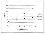
放射温度計を用いて、所定の時刻に繊維強化樹脂の表面温度を測定した。表面温度の測定点は、上端位置P1、中央位置P2及び下端位置P3とされた(図3参照)。繊維強化樹脂の上端から下端までの距離は、400mmであった。上端位置P1は、繊維強化樹脂の上端からの距離が30mmの地点であった。下端位置P3は、繊維強化樹脂の下端からの距離が30mmの地点であった。中央位置P2は、位置P1と位置P2との間を2等分する位置であった。実施例1におけるマイクロ波の照射時間と表面温度との関係を示すグラフが図4に示される。 The surface temperature of the fiber-reinforced resin was measured at a predetermined time using a radiation thermometer. The measurement points of the surface temperature were the upper end position P1, the center position P2, and the lower end position P3 (see FIG. 3). The distance from the upper end to the lower end of the fiber reinforced resin was 400 mm. The upper end position P1 was a point at a distance of 30 mm from the upper end of the fiber reinforced resin. The lower end position P3 was a point at a distance of 30 mm from the lower end of the fiber reinforced resin. The center position P2 is a position that bisects the position P1 and the position P2. FIG. 4 is a graph showing the relationship between the microwave irradiation time and the surface temperature in Example 1.
[実施例2]
マンドレルの材質をステンレス鋼に変更した他は実施例1と同様にして、実施例2における各地点の温度を測定した。このステンレス鋼の熱伝導率は、20W/(m・k)であった。実施例2におけるマイクロ波の照射時間と表面温度との関係を示すグラフが図5に示される。[Example 2]
The temperature at each point in Example 2 was measured in the same manner as in Example 1 except that the material of the mandrel was changed to stainless steel. The thermal conductivity of this stainless steel was 20 W / (mk). FIG. 5 is a graph showing the relationship between the microwave irradiation time and the surface temperature in Example 2.
[比較例]
マンドレルの材質をPTFE(ポリテトラフルオロエチレン)に変更した他は実施例1と同様にして、比較例における各地点の温度を測定した。このPTFEの熱伝導率は、0.2W/(m・k)であった。比較例におけるマイクロ波の照射時間と表面温度との関係を示すグラフが図6に示される。[Comparative example]
The temperature at each point in the comparative example was measured in the same manner as in Example 1 except that the material of the mandrel was changed to PTFE (polytetrafluoroethylene). The thermal conductivity of this PTFE was 0.2 W / (mk). FIG. 6 is a graph showing the relationship between the microwave irradiation time and the surface temperature in the comparative example.
実施例1では、マイクロ波の出力が3.5kWとされた。図4が示すように、端部P1、P3と中央位置P2とがほぼ同じ速度で昇温していることが確認された。 In Example 1, the microwave output was set to 3.5 kW. As shown in FIG. 4, it was confirmed that the temperatures of the end portions P1, P3 and the center position P2 were raised at substantially the same speed.
実施例2でも、端部P1、P3と中央位置P2とがほぼ同じ速度で昇温していることが確認された。ただし、実施例1に比べると温度のバラツキが大きかった。なお実施例2では、マイクロ波の出力が3.0kWとされた。 Also in Example 2, it was confirmed that the temperatures of the ends P1, P3 and the center position P2 were raised at substantially the same speed. However, compared to Example 1, the temperature variation was large. In Example 2, the microwave output was set to 3.0 kW.
比較例では、中央位置P2の昇温速度が遅く、端部P1、P3の昇温速度が速かった。このため、温度のバラツキが大きかった。なお、比較例では、マイクロ波の出力が1.5kWの状態で、加熱開始から9分後に、端部から煙が発生した。このため、マイクロ波の出力を1.5kWよりも大きくすることができなかった。この結果、中央位置P2の温度が非常に低く、中央位置P2を適切に硬化させることが困難であった。 In the comparative example, the heating rate at the center position P2 was slow, and the heating rate at the ends P1 and P3 was fast. For this reason, temperature variation was large. In the comparative example, smoke was generated from the end 9 minutes after the start of heating with the microwave output at 1.5 kW. For this reason, the microwave output could not be made larger than 1.5 kW. As a result, the temperature at the central position P2 was extremely low, and it was difficult to appropriately cure the central position P2.
本発明者は当初、PTFEのマンドレルのほうが加熱効率が高く好ましいと考えていた。PTFE分子は非共有電子対を有さず無極性であるため、マイクロ波によってほとんど加熱されない。よって、PTFEを用いることで、エネルギー損失が抑制され、加熱効率が高まると考えた。加えて、PTFEはマイクロ波を透過させるため、加熱の均一性にも有利と考えた。一方、マンドレルが金属である場合、マイクロ波が金属を透過できないので、加熱が不均一になりやすいと考えた。加えて、金属であるマンドレルには、マイクロ波によって電流が流れ、スパーク(火花)が生じるおそれがあると考えた。ところが実際に実験してみると、上述のように、PTFE製のマンドレルでは加熱が不均一となり、端部において煙が発生した。一方、金属製のマンドレルでは加熱が均一となり、良好に繊維強化樹脂を硬化させることができた。このように、予想に反した結果が得られた。 The present inventor initially thought that a PTFE mandrel was preferred because of its higher heating efficiency. Since the PTFE molecule has no lone pair and is nonpolar, it is hardly heated by the microwave. Therefore, it was considered that by using PTFE, energy loss was suppressed and heating efficiency was increased. In addition, PTFE is considered to be advantageous for heating uniformity because it transmits microwaves. On the other hand, when the mandrel was made of a metal, it was considered that the heating was likely to be uneven because microwaves could not pass through the metal. In addition, it was considered that electric current might flow through the mandrel, which is a metal, due to microwaves, which could cause sparks. However, when the experiment was actually performed, as described above, the heating was uneven in the PTFE mandrel, and smoke was generated at the end. On the other hand, in the case of the metal mandrel, the heating became uniform, and the fiber reinforced resin could be cured well. Thus, unexpected results were obtained.
以上に示されるように、実施例の製造方法は、比較例の製造方法に比べて評価が高い。この評価結果から、本発明の優位性は明らかである。 As shown above, the manufacturing method of the example has a higher evaluation than the manufacturing method of the comparative example. From the evaluation results, the superiority of the present invention is clear.
以上説明された方法は、あらゆる繊維強化樹脂に適用されうる。 The method described above can be applied to any fiber reinforced resin.
100・・・マンドレル
200・・・プリプレグ
300・・・FRP巻回体100: mandrel 200: prepreg 300: FRP wound body
Claims (2)
Translated fromJapaneseマイクロ波を照射して上記繊維強化樹脂を加熱及び硬化させる第2工程と、
を含む繊維強化樹脂成形体の製造方法であって、
上記高熱伝導性部材が、金属部材のマンドレルであり、
上記第1工程において、上記繊維強化樹脂が上記マンドレルに巻き付けられ、
上記マンドレルの熱伝導率が50W/(m・k)以上であり、
上記マンドレルに固定された硬化前の上記繊維強化樹脂の厚みが1mm以下であり、
上記第2工程では、上記マンドレルをその軸方向が鉛直方向になるようにして、上方から上記マイクロ波が照射される製造方法。A first step of fixing the fiber reinforced resin before curing to the high heat conductive member,
A second step of irradiating microwaves to heat and cure the fiber reinforced resin,
A methodfor producing a fiber-reinforced resin molded article, comprising:
The high thermal conductive member is a metal member mandrel,
In the first step, the fiber reinforced resin is wound around the mandrel,
The thermal conductivity of the mandrel is 50 W / (mk) or more;
The thickness of the fiber-reinforced resin before curing fixed to the mandrel is 1 mm or less,
In the second step, the mandrel is arranged such that the axial direction of the mandrel is vertical and the microwave is irradiated from above.
Priority Applications (1)
| Application Number | Priority Date | Filing Date | Title |
|---|---|---|---|
| JP2015207033AJP6668675B2 (en) | 2015-10-21 | 2015-10-21 | Method for producing fiber-reinforced resin molded article |
Applications Claiming Priority (1)
| Application Number | Priority Date | Filing Date | Title |
|---|---|---|---|
| JP2015207033AJP6668675B2 (en) | 2015-10-21 | 2015-10-21 | Method for producing fiber-reinforced resin molded article |
Publications (2)
| Publication Number | Publication Date |
|---|---|
| JP2017077685A JP2017077685A (en) | 2017-04-27 |
| JP6668675B2true JP6668675B2 (en) | 2020-03-18 |
Family
ID=58664985
Family Applications (1)
| Application Number | Title | Priority Date | Filing Date |
|---|---|---|---|
| JP2015207033AExpired - Fee RelatedJP6668675B2 (en) | 2015-10-21 | 2015-10-21 | Method for producing fiber-reinforced resin molded article |
Country Status (1)
| Country | Link |
|---|---|
| JP (1) | JP6668675B2 (en) |
Family Cites Families (9)
| Publication number | Priority date | Publication date | Assignee | Title |
|---|---|---|---|---|
| JPS5228133B2 (en)* | 1973-08-28 | 1977-07-25 | ||
| JPS5438376A (en)* | 1977-09-01 | 1979-03-22 | Mitsubishi Rayon Co Ltd | Molding of fiber reinforced plastic pipe |
| US4943334A (en)* | 1986-09-15 | 1990-07-24 | Compositech Ltd. | Method for making reinforced plastic laminates for use in the production of circuit boards |
| JPH026107A (en)* | 1988-06-27 | 1990-01-10 | Agency Of Ind Science & Technol | Heating and curing process of fiber reinforced plastic by microwave |
| US6893733B2 (en)* | 2000-07-07 | 2005-05-17 | Delphi Technologies, Inc. | Modified contoured crushable structural members and methods for making the same |
| JP4478621B2 (en)* | 2005-07-07 | 2010-06-09 | 丸栄化工株式会社 | Manufacturing method of fiber reinforced resin cylindrical body |
| DE102007050312A1 (en)* | 2007-10-18 | 2009-04-23 | Deutsches Zentrum für Luft- und Raumfahrt e.V. | Method for producing a fiber composite component |
| JP2012081621A (en)* | 2010-10-08 | 2012-04-26 | Toyota Motor Corp | Apparatus and method for manufacturing frp molded product |
| JP2012148521A (en)* | 2011-01-20 | 2012-08-09 | Toyota Motor Corp | Method and apparatus for manufacturing tank |
- 2015
- 2015-10-21JPJP2015207033Apatent/JP6668675B2/ennot_activeExpired - Fee Related
Also Published As
| Publication number | Publication date |
|---|---|
| JP2017077685A (en) | 2017-04-27 |
Similar Documents
| Publication | Publication Date | Title |
|---|---|---|
| US5338497A (en) | Induction heating method for forming composite articles | |
| CN106113484B (en) | A kind of connection method of thermoplastic composite and metal | |
| JP6770505B2 (en) | A device for heating the molding surface of a mold | |
| US8506873B2 (en) | Method for producing a fibre-composite component | |
| US8354624B2 (en) | Device for curing a plastic material | |
| US20140190629A1 (en) | Induction heating compaction system | |
| JP2007535786A (en) | Method for heating a material to produce an object and device implementing said method | |
| WO2012149973A1 (en) | Method and device for curing a thermosetting polymer | |
| CA2975075C (en) | Adhesive and structure, and adhesion method | |
| JP5213838B2 (en) | Inductor for electromagnetic tube forming and manufacturing method thereof | |
| EP3263633B1 (en) | Curing method of resin composite material | |
| JP2019532847A (en) | Fiber reinforced polymer manufacturing | |
| JP6668675B2 (en) | Method for producing fiber-reinforced resin molded article | |
| JP2009208301A (en) | Method and apparatus for repairing composite material | |
| KR20150081423A (en) | Compliant layer for matched tool molding of uneven composite preforms | |
| WO2012149972A1 (en) | Method for heating a fiber-reinforced polymer article | |
| JP2933310B1 (en) | Heating element used for thermal welding of thermoplastic resin molded products | |
| JP5244081B2 (en) | Inductor for electromagnetic tube forming and manufacturing method thereof | |
| US5357085A (en) | Induction heating of polymer matrix composite fiber strands | |
| JP7227342B2 (en) | Mold with thermally conductive flange | |
| JP2010533238A (en) | Powder metallurgy method for producing extruded profiles | |
| KR102314956B1 (en) | Device for heating a mold | |
| JP6508510B2 (en) | Carbon fiber reinforced composite material compact, method of manufacturing the same, and method of repairing carbon fiber reinforced composite material compact | |
| JP2023503598A (en) | Fiber Reinforced Polymer Composite Structure and Its Electromagnetic Induction Manufacturing Method | |
| BAKIRCI et al. | Investigation and optimization of resistance implant welding of polypropylene sheets |
Legal Events
| Date | Code | Title | Description |
|---|---|---|---|
| RD01 | Notification of change of attorney | Free format text:JAPANESE INTERMEDIATE CODE: A7426 Effective date:20170131 | |
| A621 | Written request for application examination | Free format text:JAPANESE INTERMEDIATE CODE: A621 Effective date:20180919 | |
| A977 | Report on retrieval | Free format text:JAPANESE INTERMEDIATE CODE: A971007 Effective date:20190814 | |
| A131 | Notification of reasons for refusal | Free format text:JAPANESE INTERMEDIATE CODE: A131 Effective date:20190820 | |
| A521 | Request for written amendment filed | Free format text:JAPANESE INTERMEDIATE CODE: A523 Effective date:20190930 | |
| TRDD | Decision of grant or rejection written | ||
| A01 | Written decision to grant a patent or to grant a registration (utility model) | Free format text:JAPANESE INTERMEDIATE CODE: A01 Effective date:20200128 | |
| A61 | First payment of annual fees (during grant procedure) | Free format text:JAPANESE INTERMEDIATE CODE: A61 Effective date:20200210 | |
| R150 | Certificate of patent or registration of utility model | Ref document number:6668675 Country of ref document:JP Free format text:JAPANESE INTERMEDIATE CODE: R150 | |
| R250 | Receipt of annual fees | Free format text:JAPANESE INTERMEDIATE CODE: R250 | |
| LAPS | Cancellation because of no payment of annual fees |