JP6668309B2 - Storage system and control method thereof - Google Patents
Storage system and control method thereofDownload PDFInfo
- Publication number
- JP6668309B2 JP6668309B2JP2017231219AJP2017231219AJP6668309B2JP 6668309 B2JP6668309 B2JP 6668309B2JP 2017231219 AJP2017231219 AJP 2017231219AJP 2017231219 AJP2017231219 AJP 2017231219AJP 6668309 B2JP6668309 B2JP 6668309B2
- Authority
- JP
- Japan
- Prior art keywords
- storage
- control unit
- node
- storage control
- chunk
- Prior art date
- Legal status (The legal status is an assumption and is not a legal conclusion. Google has not performed a legal analysis and makes no representation as to the accuracy of the status listed.)
- Active
Links
Images


Classifications
- G—PHYSICS
- G06—COMPUTING OR CALCULATING; COUNTING
- G06F—ELECTRIC DIGITAL DATA PROCESSING
- G06F3/00—Input arrangements for transferring data to be processed into a form capable of being handled by the computer; Output arrangements for transferring data from processing unit to output unit, e.g. interface arrangements
- G06F3/06—Digital input from, or digital output to, record carriers, e.g. RAID, emulated record carriers or networked record carriers
- G06F3/0601—Interfaces specially adapted for storage systems
- G06F3/0628—Interfaces specially adapted for storage systems making use of a particular technique
- G06F3/0655—Vertical data movement, i.e. input-output transfer; data movement between one or more hosts and one or more storage devices
- G06F3/0659—Command handling arrangements, e.g. command buffers, queues, command scheduling
- G—PHYSICS
- G06—COMPUTING OR CALCULATING; COUNTING
- G06F—ELECTRIC DIGITAL DATA PROCESSING
- G06F11/00—Error detection; Error correction; Monitoring
- G06F11/07—Responding to the occurrence of a fault, e.g. fault tolerance
- G06F11/16—Error detection or correction of the data by redundancy in hardware
- G06F11/20—Error detection or correction of the data by redundancy in hardware using active fault-masking, e.g. by switching out faulty elements or by switching in spare elements
- G06F11/2053—Error detection or correction of the data by redundancy in hardware using active fault-masking, e.g. by switching out faulty elements or by switching in spare elements where persistent mass storage functionality or persistent mass storage control functionality is redundant
- G06F11/2089—Redundant storage control functionality
- G06F11/2092—Techniques of failing over between control units
- G—PHYSICS
- G06—COMPUTING OR CALCULATING; COUNTING
- G06F—ELECTRIC DIGITAL DATA PROCESSING
- G06F11/00—Error detection; Error correction; Monitoring
- G06F11/07—Responding to the occurrence of a fault, e.g. fault tolerance
- G06F11/16—Error detection or correction of the data by redundancy in hardware
- G06F11/20—Error detection or correction of the data by redundancy in hardware using active fault-masking, e.g. by switching out faulty elements or by switching in spare elements
- G06F11/2053—Error detection or correction of the data by redundancy in hardware using active fault-masking, e.g. by switching out faulty elements or by switching in spare elements where persistent mass storage functionality or persistent mass storage control functionality is redundant
- G06F11/2094—Redundant storage or storage space
- G—PHYSICS
- G06—COMPUTING OR CALCULATING; COUNTING
- G06F—ELECTRIC DIGITAL DATA PROCESSING
- G06F3/00—Input arrangements for transferring data to be processed into a form capable of being handled by the computer; Output arrangements for transferring data from processing unit to output unit, e.g. interface arrangements
- G06F3/06—Digital input from, or digital output to, record carriers, e.g. RAID, emulated record carriers or networked record carriers
- G06F3/0601—Interfaces specially adapted for storage systems
- G06F3/0602—Interfaces specially adapted for storage systems specifically adapted to achieve a particular effect
- G06F3/0614—Improving the reliability of storage systems
- G06F3/0619—Improving the reliability of storage systems in relation to data integrity, e.g. data losses, bit errors
- G—PHYSICS
- G06—COMPUTING OR CALCULATING; COUNTING
- G06F—ELECTRIC DIGITAL DATA PROCESSING
- G06F3/00—Input arrangements for transferring data to be processed into a form capable of being handled by the computer; Output arrangements for transferring data from processing unit to output unit, e.g. interface arrangements
- G06F3/06—Digital input from, or digital output to, record carriers, e.g. RAID, emulated record carriers or networked record carriers
- G06F3/0601—Interfaces specially adapted for storage systems
- G06F3/0628—Interfaces specially adapted for storage systems making use of a particular technique
- G06F3/0629—Configuration or reconfiguration of storage systems
- G06F3/0631—Configuration or reconfiguration of storage systems by allocating resources to storage systems
- G—PHYSICS
- G06—COMPUTING OR CALCULATING; COUNTING
- G06F—ELECTRIC DIGITAL DATA PROCESSING
- G06F3/00—Input arrangements for transferring data to be processed into a form capable of being handled by the computer; Output arrangements for transferring data from processing unit to output unit, e.g. interface arrangements
- G06F3/06—Digital input from, or digital output to, record carriers, e.g. RAID, emulated record carriers or networked record carriers
- G06F3/0601—Interfaces specially adapted for storage systems
- G06F3/0628—Interfaces specially adapted for storage systems making use of a particular technique
- G06F3/0638—Organizing or formatting or addressing of data
- G06F3/064—Management of blocks
- G—PHYSICS
- G06—COMPUTING OR CALCULATING; COUNTING
- G06F—ELECTRIC DIGITAL DATA PROCESSING
- G06F3/00—Input arrangements for transferring data to be processed into a form capable of being handled by the computer; Output arrangements for transferring data from processing unit to output unit, e.g. interface arrangements
- G06F3/06—Digital input from, or digital output to, record carriers, e.g. RAID, emulated record carriers or networked record carriers
- G06F3/0601—Interfaces specially adapted for storage systems
- G06F3/0628—Interfaces specially adapted for storage systems making use of a particular technique
- G06F3/0638—Organizing or formatting or addressing of data
- G06F3/0644—Management of space entities, e.g. partitions, extents, pools
- G—PHYSICS
- G06—COMPUTING OR CALCULATING; COUNTING
- G06F—ELECTRIC DIGITAL DATA PROCESSING
- G06F3/00—Input arrangements for transferring data to be processed into a form capable of being handled by the computer; Output arrangements for transferring data from processing unit to output unit, e.g. interface arrangements
- G06F3/06—Digital input from, or digital output to, record carriers, e.g. RAID, emulated record carriers or networked record carriers
- G06F3/0601—Interfaces specially adapted for storage systems
- G06F3/0668—Interfaces specially adapted for storage systems adopting a particular infrastructure
- G06F3/067—Distributed or networked storage systems, e.g. storage area networks [SAN], network attached storage [NAS]
- G—PHYSICS
- G06—COMPUTING OR CALCULATING; COUNTING
- G06F—ELECTRIC DIGITAL DATA PROCESSING
- G06F3/00—Input arrangements for transferring data to be processed into a form capable of being handled by the computer; Output arrangements for transferring data from processing unit to output unit, e.g. interface arrangements
- G06F3/06—Digital input from, or digital output to, record carriers, e.g. RAID, emulated record carriers or networked record carriers
- G06F3/0601—Interfaces specially adapted for storage systems
- G06F3/0668—Interfaces specially adapted for storage systems adopting a particular infrastructure
- G06F3/0671—In-line storage system
- G06F3/0683—Plurality of storage devices
Landscapes
- Engineering & Computer Science (AREA)
- Theoretical Computer Science (AREA)
- Physics & Mathematics (AREA)
- General Engineering & Computer Science (AREA)
- General Physics & Mathematics (AREA)
- Human Computer Interaction (AREA)
- Quality & Reliability (AREA)
- Computer Security & Cryptography (AREA)
- Information Retrieval, Db Structures And Fs Structures Therefor (AREA)
Description
Translated fromJapanese本発明は記憶システム及びその制御方法に関し、例えば、それぞれ1又は複数のSDS(Software Defined Storage)が実装された複数のストレージノードを備える情報処理システムに適用して好適なものである。なお、以下において、SDSとは、ストレージ機能を有するソフトウェアを汎用のサーバ装置に実装することにより構築されるストレージ装置を指す。 The present invention relates to a storage system and a control method thereof, and is suitably applied to, for example, an information processing system including a plurality of storage nodes each mounted with one or a plurality of SDSs (Software Defined Storages). In the following, the SDS refers to a storage device constructed by mounting software having a storage function on a general-purpose server device.
従来、情報処理システムにおいて、複数のストレージサブシステム間で容量を融通し合う技術が提案されている。 Conventionally, in an information processing system, a technique for accommodating a capacity between a plurality of storage subsystems has been proposed.
例えば、ホストから入出力コマンドを受信し、ホストに第1のボリュームを提供する第1のコントローラを含む第1のストレージシステムと、ホストから入出力コマンドを受信し、ホストに第2のボリュームを提供する第2のコントローラを含む第2のストレージシステムとを設け、第1のボリュームのうちの第1の記憶領域を第1のコントローラによって第1のプールから割り当て、第1のボリュームのうちの第2の記憶領域を第1のコントローラによって第2のプールから割り当て、第2のボリュームのうちの第3の記憶領域を第2のコントローラによって第1のプールから割り当て、第2のボリュームのうちの第4の記憶領域を第2のコントローラによって第2のプールから割り当てる技術がある。例えば、下記特許文献1に記載の技術がある。 For example, a first storage system including a first controller that receives an I / O command from a host and provides a first volume to the host, and receives a I / O command from the host and provides a second volume to the host A second storage system that includes a second controller that performs a second storage system that allocates a first storage area of the first volume from a first pool by the first controller, and a second storage system of the first volume. Is allocated by the first controller from the second pool, a third storage area of the second volume is allocated by the second controller from the first pool, and a fourth storage area of the second volume is allocated. There is a technique of allocating the storage area of the second pool from the second pool by the second controller. For example, there is a technique described in
分散ストレージシステム全体としての可用性及び信頼性の向上を考えた場合、コントローラを冗長化しておくことが望ましい。またホストからストレージシステムに書き込まれたデータについても、システム内で冗長化して記憶しておくことが可用性及び信頼性の点からも望ましい。 When considering the availability and reliability of the entire distributed storage system, it is desirable to make the controllers redundant. It is also desirable from the viewpoint of availability and reliability that data written from the host to the storage system be stored redundantly in the system.
ただし、コントローラ及びデータを冗長化するに際しては、複数のノードで構成される分散ストレージシステム全体としての応答性能やデータ保護の観点から、冗長化したデータを何処に配置すべきかを十分に検討する必要がある。 However, when making the controller and data redundant, it is necessary to carefully consider where the redundant data should be placed from the viewpoint of the response performance and data protection of the distributed storage system composed of multiple nodes as a whole. There is.
本発明は以上の点を考慮してなされたもので、システム全体としての応答性能の劣化を防止しながらデータ保護を行い得る記憶システム及びその制御方法を提案しようとするものである。 The present invention has been made in consideration of the above points, and has as its object to propose a storage system capable of performing data protection while preventing deterioration of response performance of the entire system, and a control method thereof.
かかる課題を解決するため本発明においては、複数のストレージノードを有する記憶システムにおいて、各々の前記ストレージノードは、クラスタ内の複数の前記ストレージノードの各記憶デバイスがそれぞれ提供する容量を管理する容量制御部と、I/O要求を受け付け、受け付けた前記I/O要求に応じたコマンドを生成して前記容量制御部に送信するストレージ制御部と、を備え、前記記憶システムは、それぞれ異なる前記ストレージノードに配置された複数の前記ストレージ制御部が、ストレージ制御部グループを構成し、前記ストレージ制御部グループの第1の前記ストレージ制御部が前記I/O要求を処理する第1の状態に設定されると共に、前記ストレージ制御部グループの第2の前記ストレージ制御部が当該I/O要求を処理しない第2の状態に設定され、前記記憶デバイスに格納されるデータを、異なるストレージノードの格納される複数のデータを組みにしてデータ冗長化しており、前記容量制御部は、前記ストレージ制御部が属するノード及び他のストレージノードの物理記憶領域を前記ストレージ制御部グループに割り当てることが可能であり、他のストレージノードの前記物理記憶領域を前記ストレージ制御部グループに割り当てる場合に、前記データ冗長化したデータの組みの他のデータと同じストレージノードに格納されないように前記他のストレージノードを選択して割り当てるようにした。In the present invention for solving the above problems, in a storage system having a plurality of storage nodes, each said storage node, capacity control for managing thecapacity of each of the plurality of storage devicesof the storage nodesin the cluster to provide each and parts, accepts theI / O request, a storage control unit which generates a corresponding to the I / O request accepted command transmitted to the capacity control unit,wherein the storage system, the storage node respectively different the storage control unit of themultiple thatarranged in the, set to a first statethat constitute the storage control unitgroup,first the storage control unitof the storage control unitgroupprocess thepre SL I / O request with thesecond of the storage control unitof the storage control unit group the I / O request Is set to a second state inwhich no sense,the data stored in the storage device, and then to the data redundancy in combination a plurality of data stored in different storage nodes, the capacity control section,the storage control unit It is possible to allocate the physical storage area of the node to which the storage node belongs and another storage node to the storage control unit group, and when allocating the physical storage area of another storage node to the storage control unit group, The other storage node is selected and assigned so as not to be stored in the same storage node as the other data of the set of data .
また本発明においては、複数のストレージノードを有する記憶システムの制御方法であって、各々の前記ストレージノードは、クラスタ内の複数の前記ストレージノードの各記憶デバイスがそれぞれ提供する容量を管理する容量制御部と、I/O要求を受け付け、受け付けた前記I/O要求に応じたコマンドを生成して前記容量制御部に送信するストレージ制御部と、を有し、前記記憶システムは、それぞれ異なる前記ストレージノードに配置された複数の前記ストレージ制御部がストレージ制御部グループを構成し、前記ストレージ制御部グループの第1の前記ストレージ制御部が前記I/O要求を受け付ける第1の状態に設定されると共に、前記ストレージ制御部グループの第2の前記ストレージ制御部が当該I/O要求を処理しない第2の状態に設定され、前記記憶デバイスに格納されるデータを、異なるストレージノードの格納される複数のデータを組みにしてデータ冗長化しており、前記容量制御部は、前記ストレージ制御部が属するノード及び他のノードの物理記憶領域を前記ストレージ制御部グループに割り当てることが可能であり、他のノードの前記物理記憶領域を前記ストレージ制御部に割り当てる場合に、前記データ冗長化したデータの組みの他のデータと同じノードに格納されないように前記他のノードを選択して割り当てるようにした。
さらに本発明においては、複数のストレージノードを有する記憶システムにおいて、各々の前記ストレージノードは、クラスタ内の複数の前記ストレージノードの各記憶デバイスがそれぞれ提供する容量を管理する容量制御部と、I/O要求を受け付け、受け付けた前記I/O要求に応じたコマンドを生成して前記容量制御部に送信するストレージ制御部と、を備え、前記記憶システムは、それぞれ異なる前記ストレージノードに配置された複数の前記ストレージ制御部が、ストレージ制御部グループを構成し、前記ストレージ制御部グループの第1の前記ストレージ制御部が前記I/O要求を処理する第1の状態に設定されると共に、前記ストレージ制御部グループの第2の前記ストレージ制御部が当該I/O要求を処理しない第2の状態に設定され、前記記憶デバイスに格納されるデータを、マスタデータ及びスレーブデータを組みにしてデータ冗長化しており、前記容量制御部は、前記ストレージ制御部が属するノード及び他のストレージノードの物理記憶領域を前記ストレージ制御部グループに割り当てることが可能であり、前記マスタデータは、前記第1の状態のストレージ制御部が配置されたストレージノードを含む第1のストレージノードグループの物理記憶領域に格納され、前記スレーブデータは、前記第2の状態のストレージ制御部が配置されたストレージノードを含む第2のストレージノードグループの物理記憶領域に格納され、前記スレーブデータを格納するストレージノードの前記物理記憶領域を前記ストレージ制御部グループに割り当てる場合に、前記マスタデータを格納する第1のストレージノードグループのストレージノードに格納されないように前記ストレージノードを選択して割り当てるようにした。Further, in the present invention, there is provided a method of controlling a storage system having a plurality of storage nodes, whereineach of the storage nodes manages a capacity provided by each storage deviceof the plurality of storage nodes in acluster. and parts, theI / O request is acknowledged, to generate corresponding to the I / O request accepted command anda storage control unit to be transmitted to the capacity control unit,said storage system, said storage mutually different a plurality of the storage control unitof nodeconstitutes a storage control unitgroup,first the storage control unitof the storage control unitgroup is set to a first statethat acceptspre SL I / O request with asecond of the storage control unitof the storage control unit group doesnot process the I / O request Is set to the second state,the data stored in the storage device, and then the data redundancy in the set a plurality of data stored in different storage nodes, the capacity controlsection,the node where the storage control unit belongs And assigning a physical storage area of another node to the storage control unit group, and when allocating the physical storage area of another node to the storage control unit, another The other node is selected and assigned so that it is not stored in the same node as the data of the above .
Further, according to the present invention,in a storage system having aplurality of storage nodes, each of the storage nodes manages a capacity provided by each storage device of the plurality of storage nodes in a cluster; A storage control unit that receives an O request, generates a command corresponding to the received I / O request, and transmits the command to the capacity control unit. The storage control unit of the storage control unit group is set to a first state in which the first storage control unit of the storage control unit group processes the I / O request, and the storage control unit Second state in which the second storage control unit of the group does not process the I / O request The data that is set and stored in the storage device is data redundant by combining master data and slave data, and the capacity control unit is a physical storage area of a node to which the storage control unit belongs and another storage node. Can be assigned to the storage control unit group, and the master data is stored in a physical storage area of a first storage node group including a storage node in which the storage control unit in the first state is arranged; The slave data is stored in a physical storage area of a second storage node group including a storage node in which the storage control unit in the second state is arranged, and stores the physical storage area of the storage node that stores the slave data. When assigning to the storage control unit group, It was allocated by selecting the storage node so as not to be stored in the storage node of the first storage node group for storing static data.
本発明の記憶システム及び容量割当て方法によれば、ストレージ制御部ペアに対して少なくとも2つの物理記憶領域が割り当てられ、これらの物理記憶領域にデータが二重化されて格納されるためデータが保護される。また、ストレージ制御部ペアに対しては、ストレージ制御部ペアを構成する一方のストレージ制御部の配置先近傍の物理記憶領域と、当該ストレージ制御部ペアを構成する他方のストレージ制御部の配置先近傍の物理記憶領域とが優先的に割り当てられるため、第1の状態に設定されたストレージ制御部や、第2の状態から第1の状態に切り替えられたストレージ制御部がこれらの物理記憶領域のうちの対応する物理記憶領域に迅速にアクセスすることができ、当該物理記憶領域に対するデータのリード/ライトを速やかに行うことができる。 According to the storage system and the capacity allocating method of the present invention, at least two physical storage areas are allocated to the storage control unit pair, and the data is duplicated and stored in these physical storage areas, so that the data is protected. . In addition, for the storage control unit pair, a physical storage area near the placement destination of one storage control unit forming the storage control unit pair and a placement location near the other storage control unit forming the storage control unit pair Of the physical storage areas, the storage control unit set to the first state and the storage control unit switched from the second state to the first state are among the physical storage areas. Can quickly access the corresponding physical storage area, and can read / write data to / from the physical storage area quickly.
本発明によれば、システム全体としての応答性能の劣化を防止しながらデータ保護を行い得る記憶システム及びその制御方法を実現できる。上記した以外の課題、構成及び効果は、以下の発明を実施するための形態の説明により明らかにされる。 According to the present invention, it is possible to realize a storage system capable of protecting data while preventing deterioration of response performance of the entire system, and a control method thereof. Problems, configurations, and effects other than those described above will be apparent from the following description of embodiments for carrying out the invention.
以下、図面を参照して、本発明の一実施の形態を詳述する。以下の記載及び図面は、本発明を説明するための例示であって、説明の明確化のため、適宜、省略及び簡略化がなされている。また、実施の形態の中で説明されている特徴の組み合わせの全てが発明の解決手段に必須であるとは限らない。本発明が実施の形態に制限されることは無く、本発明の思想に合致するあらゆる応用例が本発明の技術的範囲に含まれる。本発明は、当業者であれば本発明の範囲内で様々な追加や変更等を行うことができる。本発明は、他の種々の形態でも実施する事が可能である。特に限定しない限り、各構成要素は複数でも単数でも構わない。 Hereinafter, an embodiment of the present invention will be described in detail with reference to the drawings. The following description and drawings are exemplifications for describing the present invention, and are omitted and simplified as appropriate for clarification of the description. Further, not all combinations of the features described in the embodiments are necessarily indispensable to the solution of the invention. The present invention is not limited to the embodiments, and any application that matches the concept of the present invention is included in the technical scope of the present invention. A person skilled in the art can make various additions and changes within the scope of the present invention. The present invention can be implemented in other various forms. Unless particularly limited, each component may be plural or singular.
以下の説明では、「テーブル」、「表」、「リスト」、「キュー」等の表現にて各種情報を説明することがあるが、各種情報は、これら以外のデータ構造で表現されていてもよい。データ構造に依存しないことを示すために「XXテーブル」、「XXリスト」等を「XX情報」と呼ぶことがある。各情報の内容を説明する際に、「識別情報」、「識別子」、「名」、「ID」、「番号」等の表現を用いるが、これらについてはお互いに置換が可能である。 In the following description, various types of information may be described using expressions such as “table”, “table”, “list”, and “queue”. However, various types of information may be expressed in other data structures. Good. The “XX table”, “XX list”, etc. may be referred to as “XX information” to indicate that the data structure does not depend on the data structure. In describing the contents of each information, expressions such as “identification information”, “identifier”, “name”, “ID”, and “number” are used, but these can be replaced with each other.
また、以下の説明では、同種の要素を区別しないで説明する場合には、参照符号又は参照符号における共通番号を使用し、同種の要素を区別して説明する場合は、その要素の参照符号を使用又は参照符号に代えてその要素に割り振られたIDを使用することがある。 Also, in the following description, the same reference numeral or a common number in the reference numeral is used when describing the same type of element without distinguishing it, and the reference numeral of the element is used when describing the same type of element distinctively. Alternatively, an ID assigned to the element may be used instead of the reference symbol.
また、以下の説明では、プログラムを実行して行う処理を説明する場合があるが、プログラムは、少なくとも1以上のプロセッサ(例えばCPU)によって実行されることで、定められた処理を、適宜に記憶資源(例えばメモリ)及び/又はインターフェースデバイス(例えば通信ポート)等を用いながら行うため、処理の主体がプロセッサとされてもよい。同様に、プログラムを実行して行う処理の主体が、プロセッサを有するコントローラ、装置、システム、計算機、ノード、ストレージシステム、ストレージ装置、サーバ、管理計算機、クライアント、又はホストであってもよい。プログラムを実行して行う処理の主体(例えばプロセッサ)は、処理の一部又は全部を行うハードウェア回路を含んでもよい。例えば、プログラムを実行して行う処理の主体は、暗号化及び復号化、又は圧縮及び伸張を実行するハードウェア回路を含んでもよい。プロセッサは、プログラムに従って動作することによって、所定の機能を実現する機能部として動作する。プロセッサを含む装置及びシステムは、これらの機能部を含む装置及びシステムである。 In the following description, processing performed by executing a program may be described, but the program is executed by at least one or more processors (for example, CPUs) to appropriately store the determined processing. The processing may be performed by using a resource (for example, a memory) and / or an interface device (for example, a communication port). Similarly, the subject of processing that executes a program may be a controller having a processor, a device, a system, a computer, a node, a storage system, a storage device, a server, a management computer, a client, or a host. A subject (for example, a processor) of the processing performed by executing the program may include a hardware circuit that performs part or all of the processing. For example, the subject of the processing performed by executing the program may include a hardware circuit that performs encryption and decryption or compression and decompression. The processor operates as a functional unit that implements a predetermined function by operating according to a program. Devices and systems including a processor are devices and systems including these functional units.
プログラムは、プログラムソースから計算機のような装置にインストールされてもよい。プログラムソースは、例えば、プログラム配布サーバ又は計算機が読み取り可能な記憶メディアであってもよい。プログラムソースがプログラム配布サーバの場合、プログラム配布サーバはプロセッサ(例えばCPU)と記憶資源を含み、記憶資源はさらに配布プログラムと配布対象であるプログラムとを記憶してよい。そして、プログラム配布サーバのプロセッサが配布プログラムを実行することで、プログラム配布サーバのプロセッサは配布対象のプログラムを他の計算機に配布してよい。また、以下の説明において、2以上のプログラムが1つのプログラムとして実現されてもよいし、1つのプログラムが2以上のプログラムとして実現されてもよい。 The program may be installed on a device such as a computer from a program source. The program source may be, for example, a program distribution server or a computer-readable storage medium. When the program source is a program distribution server, the program distribution server includes a processor (eg, a CPU) and a storage resource, and the storage resource may further store a distribution program and a program to be distributed. When the processor of the program distribution server executes the distribution program, the processor of the program distribution server may distribute the distribution target program to another computer. Further, in the following description, two or more programs may be realized as one program, or one program may be realized as two or more programs.
(1)第1の実施の形態
(1−1)本実施の形態による情報処理システムの構成
図1は、本実施の形態による情報処理システム1の構成を示す図である。この情報処理システム1は、例えばファイバーチャネル(Fibre Channel)、イーサネット(登録商標)又はLAN(Local Area Network)などから構成されるネットワーク2を介して相互に接続された複数のホスト装置3と、複数のストレージノード4と、管理ノード5とを備えて構成されている。(1) First Embodiment (1-1) Configuration of Information Processing System According to Present Embodiment FIG. 1 is a diagram illustrating a configuration of an
ホスト装置3は、ユーザ操作や実装されたアプリケーションプログラムからの要求に応じてストレージノード4に対してリード要求又はライト要求(以下、適宜、これらをまとめてI/O(Input/Output)要求と呼ぶ)を送信する汎用のコンピュータ装置である。なお、ホスト装置3は、仮想マシンのような仮想的なコンピュータ装置であってもよい。 The
ストレージノード4は、ホスト装置3に対してデータを読み書きするための記憶領域を提供する物理サーバ装置であり、図2に示すように、内部ネットワーク10を介して相互に接続されたCPU(Central Processing Unit)11、メモリ12、複数の記憶デバイス13及び通信装置14を備えて構成される。各ストレージノード4は、CPU11、メモリ12、記憶デバイス13、通信装置14を、それぞれ1以上備える。 The
CPU11は、ストレージノード4全体の動作制御を司るプロセッサである。またメモリ12は、SRAM(Static RAM(Random Access Memory))やDRAM(Dynamic RAM)などの揮発性の半導体メモリから構成され、各種プログラムや必要なデータを一時的に保持するために利用される。メモリ12に格納されたプログラムを、少なくとも1以上のCPU11が実行することにより、後述のようなストレージノード4全体としての各種処理が実行される。 The
記憶デバイス13は、SSD(Solid State Drive)、SAS(Serial Attached SCSI(Small Computer System Interface))ハードディスクドライブ又はSATA(Serial
ATA(Advanced Technology Attachment))ハードディスクドライブなどの1又は複数種類の大容量の不揮発性記憶装置から構成され、ホスト装置3(図1)からのライト/リード要求(以下、これをI/O(Input/Output)要求と呼ぶ)に応じてデータをリード/ライトするための物理的な記憶領域を提供する。The
An ATA (Advanced Technology Attachment)) is composed of one or more types of large-capacity non-volatile storage devices such as a hard disk drive, and receives a write / read request (hereinafter referred to as an I / O (Input / Output) request from the host device 3 (FIG. 1). / Output), which provides a physical storage area for reading / writing data in response to a request.
通信装置14は、ストレージノード4がネットワーク2(図1)を介してホスト装置3や、他のストレージノード4又は管理ノード5と通信を行うためのインタフェースであり、例えばNIC(Network Interface Card)やFC(Fibre Channel)カードなどから構成される。通信装置14は、ホスト装置3、他のストレージノード4又は管理ノード5との通信時におけるプロトコル制御を行う。 The
管理ノード5は、システム管理者が本情報処理システム1全体を管理するために利用するコンピュータ装置である。管理ノード5は、複数のストレージノード4をクラスタ6と呼ぶグループとして管理する。なお、図1では、クラスタ6が1つのみ設けられた例を示しているが、情報処理システム1内に複数のクラスタ6を設けるようにしてもよい。クラスタ6は、分散ストレージシステムと呼ばれてもよい。 The
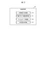
図3は、本実施の形態によるストレージノード4の論理構成を示す。この図3に示すように、各ストレージノード4は、フロントエンドドライバ20及びバックエンドドライバ21と、1又は複数のストレージ制御部22と、容量制御部23とを備える。 FIG. 3 shows a logical configuration of the
フロントエンドドライバ20は、通信装置14(図2)を制御し、ストレージ制御部22に対してホスト装置3や、他のストレージノード4又は管理ノード5との通信時における抽象化したインタフェースをCPU11(図2)に提供する機能を有するソフトウェアである。またバックエンドドライバ21は、自ストレージノード4内の各記憶デバイス13(図2)を制御し、これら記憶デバイス13との通信時における抽象化したインタフェースをCPU11に提供する機能を有するソフトウェアである。 The front-
ストレージ制御部22は、SDS(Software Defined Storage)のコントローラとして機能するソフトウェアである。ストレージ制御部22は、ストレージ制御ソフトウェアや、ストレージ制御プログラムと呼ばれてもよい。ストレージ制御部22は、ホスト装置3からのI/O要求を受け付け、当該I/O要求に応じたI/Oコマンドを容量制御部23に発行する。 The
本実施の形態の場合、ストレージノード4に実装された各ストレージ制御部22は、別のストレージノード4に配置された他のストレージ制御部22と共に冗長化構成を構成するペアとして管理される。以下においては、このペアをストレージ制御部ペア25と呼ぶものとする。 In the case of the present embodiment, each
なお図3では、2つのストレージ制御部22により1つのストレージ制御部ペア25が構成される場合を示しており、以下においても、2つのストレージ制御部22によりストレージ制御部ペア25が構成されるものとして説明を進めるが、3つ以上のストレージ制御部22により1つの冗長化構成を構成するようにしてもよい。 FIG. 3 shows a case where one storage
ストレージ制御部ペア25では、一方のストレージ制御部22がホスト装置3からのI/O要求を受け付けることができる状態(現用系の状態であり、以下、これをアクティブモードと呼ぶ)に設定され、他方のストレージ制御部22がホスト装置3からのリード要求やライト要求を受け付けない状態(待機系の状態であり、以下、これをパッシブモードと呼ぶ)に設定される。 In the storage
そしてストレージ制御部ペア25では、アクティブモードに設定されたストレージ制御部22(以下、これをアクティブストレージ制御部22と呼ぶ)やそのアクティブストレージ制御部22が配置されたストレージノード4に障害が発生した場合などに、それまでパッシブモードに設定されていたストレージ制御部22(以下、これをパッシブストレージ制御部22と呼ぶ)の状態がアクティブモードに切り替えられる。これにより、アクティブストレージ制御部22が稼働し得なくなった場合に、当該アクティブストレージ制御部22が実行していたI/O処理を、パッシブストレージ制御部22により引き継ぐことができる。 In the storage
容量制御部23は、各ストレージ制御部ペア25に対して自ストレージノード4内又は他のストレージノード4内の記憶デバイス13が提供する物理的な記憶領域を割り当てると共に、ストレージ制御部22から与えられる上述のI/Oコマンドに従って、指定されたデータを対応する記憶デバイス13にリード/ライトする機能を有するソフトウェアである。容量制御部23は、容量制御ソフトウェアや、容量制御プログラムと呼ばれてもよい。 The
この場合、容量制御部23は、ストレージ制御部ペア25に対して他のストレージノード4内の記憶デバイス13が提供する物理的な記憶領域を割り当てたときには、当該他のストレージノード4に実装された容量制御部23と協働して、その容量制御部23との間でネットワーク2を介してデータをやり取りすることにより、そのストレージ制御部ペア25のアクティブストレージ制御部22から与えられたI/Oコマンドに従ってそのデータをその記憶領域にリード/ライトする。 In this case, when the
以上の構成を有する本情報処理システム1において、容量制御部23は、図4に示すように、各ストレージノード4内の記憶デバイス13がそれぞれ提供する物理的な記憶領域を、それぞれ所定大きさの物理記憶領域(以下、これを物理チャンクと呼ぶ)PCに分割して管理する。 In the
また容量制御部23は、各ストレージ制御部ペア25(図3)に対してそれぞれ専用のプールPLを対応付け、これらプールPLに物理チャンクPCと同じ大きさの論理的な記憶領域(以下、これを論理チャンク)LCを適宜割り当て、この論理チャンクLCに対して1又は複数の物理チャンクPCを対応付ける。 Further, the
さらに各ストレージ制御部ペア25のプールPL上には1又は複数の仮想的な論理ボリューム(以下、これを仮想ボリュームと呼ぶ)VVOLが定義され、これらの仮想ボリュームVVOLがホスト装置3に提供される。 Further, one or a plurality of virtual logical volumes (hereinafter, referred to as virtual volumes) VVOL are defined on the pool PL of each storage
そしてホスト装置3は、かかる仮想ボリュームVVOLにデータをライトする場合、そのデータのライト先の仮想ボリューム(以下、これをライト対象仮想ボリュームと呼ぶ)VVOLの識別子(LUN:Logical Unit Number)と、そのライト対象仮想ボリュームVVOLにおけるそのデータのライト先の領域(以下、これをライト先領域と呼ぶ)WARとを指定したライト要求を、対応するクラスタ6内のいずれかのストレージノード4に送信する。 When writing data to the virtual volume VVOL, the
このライト要求を受信したストレージノード4のフロントエンドドライバ20は、受信したライト要求において指定されたライト対象仮想ボリュームVVOLとプールPLを介して対応付けられたストレージ制御部ペア25(図3)のアクティブストレージ制御部22(図3)又はパッシブストレージ制御部22が配置されている各ストレージノード4のフロントエンドドライバ20にそのライト要求、及び、当該ライト要求と共にホスト装置3から送信されてきたライト対象のデータ(以下、これをライトデータと呼ぶ)を転送する。 Upon receiving this write request, the front-
また、このライト要求及びライトデータを受領したストレージノード4のフロントエンドドライバ20は、これらライト要求及びライトデータを、ライト要求において指定されたライト対象仮想ボリュームVVOLとプールPLを介して対応付けられたストレージ制御部ペア25のストレージ制御部22に引き渡す。 The front-
そして、これらライト要求及びライトデータが引き渡されたストレージ制御部22のうちのアクティブストレージ制御部22は、ライト対象仮想ボリュームVVOL内のライト先領域WARに対して、当該ライト対象仮想ボリュームVVOLと対応付けられたプールPLを構成する論理チャンクLCから必要に応じて記憶領域(以下、これを論理領域と呼ぶ)を割り当てる。 The active
また、かかるアクティブストレージ制御部22は、ライト要求において指定されたライト対象仮想ボリュームVVOL内のライト先領域WARのアドレスを、そのライト先領域WARに論理領域を割り当てた論理チャンクLCのチャンク番号と、当該論理領域のオフセット位置とに変換したI/Oコマンドを生成し、生成したI/Oコマンドをライトデータと共に自ストレージノード4内の容量制御部23に送信する。 The active
そして容量制御部23は、このI/Oコマンド及びライトデータを受信すると、当該I/Oコマンドで指定された論理チャンクLCに対応付けた各物理チャンクPCをそれぞれ提供する各記憶デバイス13内のかかるオフセット位置の記憶領域にデータをそれぞれ格納する。 Then, when receiving the I / O command and the write data, the
このようにして本情報処理システム1では、ホスト装置3からのデータが対応する論理チャンクLCに対応付けられた複数の物理チャンクPCに冗長化されて格納される。このため論理チャンクLCに割り当てられる物理チャンクPCの数は、その情報処理システム1における冗長化方式の設定内容によって決定される。 In this way, in the
例えば、データを二重化して記憶する設定の場合には、1つの論理チャンクLCに対して2つの物理チャンクPCが対応付けられ、データを三重化以上に多重化して記憶する設定の場合や、Erasure-Codingのようにデータから冗長化データを作成して記憶する設定がなされている場合などには、3つ以上の必要な数の物理チャンクPCが1つの論理チャンクLCに対応付けられる。 For example, in the case of setting for duplicating and storing data, two physical chunks PC are associated with one logical chunk LC, and in the case of setting for multiplexing and storing data more than tripled, or for erasure. In a case where a setting is made to create and store redundant data from data, such as -Coding, three or more required physical chunks PC are associated with one logical chunk LC.
なお1つの論理チャンクLCに複数の物理チャンクPCが対応付けられ、これら複数の物理チャンクPCにデータを多重化して格納する場合、これら複数の物理チャンクPCの中から1つの物理チャンクPCが「マスタ」に設定され、残りの物理チャンクPCがすべて「ミラー」に設定される。そして、後述のように、物理チャンクPCからのデータリードは「マスタ」に設定された物理チャンクPCから行われる。またEC(Erasure Coding)の場合には、1つの論理チャンクLCに複数の物理チャンクPCが対応付けられ、これら複数の物理チャンクPCにマスタデータ及び冗長データが所定パターンで格納される。 In addition, when a plurality of physical chunk PCs are associated with one logical chunk LC and data is multiplexed and stored in the plurality of physical chunk PCs, one physical chunk PC among the plurality of physical chunk PCs is referred to as a “master”. ”, And all the remaining physical chunk PCs are set to“ mirror ”. Then, as described later, data read from the physical chunk PC is performed from the physical chunk PC set as “master”. In the case of EC (Erasure Coding), a plurality of physical chunks PC are associated with one logical chunk LC, and master data and redundant data are stored in the plurality of physical chunks PC in a predetermined pattern.
一方、ホスト装置3は、仮想ボリュームVVOLからデータを読み出す場合、その仮想ボリューム(以下、これをリード対象仮想ボリュームと呼ぶ)VVOLのLUNと、そのリード対象仮想ボリュームVVOLにおけるそのデータのリード先の記憶領域(以下、これをリード先領域と呼ぶ)とを指定したリード要求をそのリード対象仮想ボリュームVVOLが含まれるクラスタ6内のいずれかのストレージノード4に送信する。 On the other hand, when reading data from the virtual volume VVOL, the
このリード要求を受信したストレージノード4のフロントエンドドライバ20は、受信したリード要求において指定されたリード対象仮想ボリュームVVOLとプールPLを介して対応付けられたストレージ制御部ペア25のアクティブストレージ制御部22又はパッシブストレージ制御部22が配置された各ストレージノード4にそのリード要求をそれぞれ転送する。 The front-
また、このリード要求を受領したかかるストレージノード4のフロントエンドドライバ20は、このリード要求を当該リード要求において指定されたリード対象仮想ボリュームVVOLとプールPLを介して対応付けられたストレージ制御部ペア25のストレージ制御部22に引き渡す。 Further, the front-
かくして、このリード要求が引き渡されたかかるストレージ制御部22のうちのアクティブストレージ制御部22は、リード対象仮想ボリュームVVOL内のリード先領域のアドレスを、当該リード先領域に論理領域を割り当てた論理チャンクLCのチャンク番号と、当該論理領域のオフセット位置とに変換したI/Oコマンドを生成し、生成したI/Oコマンドを自ストレージノード4内の容量制御部23に送信する。 Thus, the active
容量制御部23は、このI/Oコマンドを受信すると、当該I/Oコマンドで指定された論理チャンクLCと対応付けられた各物理チャンクPCのうち、「マスタ」に設定された物理チャンクPC内のI/Oコマンドで指定されたオフセット位置の記憶領域からデータを読み出し、読み出したデータをリードデータとしてI/Oコマンドの送信元のアクティブストレージ制御部22に転送する。かくして、このリードデータは、この後、かかるアクティブストレージ制御部22によりネットワーク2を介してかかるリード要求の送信元のホスト装置3に転送される。 When receiving the I / O command, the
(1−2)論理チャンクに対する物理チャンクの割当て
ところで、上述のように1つの論理チャンクLCに複数の物理チャンクPCを対応付け、これらの物理チャンクPCにデータをそれぞれ格納することによりデータを冗長化する冗長化方式を採用する場合、データ保護の観点からも、1つの論理チャンクLCに対応付ける複数の物理チャンクPCをそれぞれ異なるストレージノード4が提供する物理チャンクPCから選択することが望ましい。これは、例えば、1つの論理チャンクLCに対して同じストレージノード4内の複数の物理チャンクPCを対応付けた場合、そのストレージノード4が障害等によりデータの読み出しを行えなくなったときにデータロストが発生することになるからである。(1-2) Assignment of Physical Chunks to Logical Chunks By the way, as described above, a plurality of physical chunks PC are associated with one logical chunk LC, and data is stored in each of these physical chunks PC to make data redundant. In the case of adopting the redundant method, it is desirable to select a plurality of physical chunk PCs associated with one logical chunk LC from physical chunk PCs provided by
そこで本情報処理システム1では、容量制御部23がストレージ制御部ペア25に論理チャンクLCを割り当て、その論理チャンクLCに複数の物理チャンクPCを対応付ける際に、これら複数の物理チャンクPCをそれぞれ互いに異なる複数のストレージノード4が提供する物理チャンクPCの中から選択することとしている。 Therefore, in the
一方で、論理チャンクLCと対応付ける物理チャンクPCを、アクティブストレージ制御部22が配置されたストレージノード4とは別のストレージノード4内の物理チャンクPCから選択することとした場合、そのアクティブストレージ制御部22からのI/Oコマンドを受領した容量制御部23(アクティブストレージ制御部22と同じストレージノード4内の容量制御部23)がその物理チャンクPCにデータをリード/ライトする際に、その物理チャンクPCを提供するストレージノード4との間の通信が必要となり、その分、システム全体としての応答性能が悪くなるという問題がある。従って、論理チャンクLCに複数の物理チャンクPCを対応付けるに際しては、その物理チャンクPCのうちの1つを、アクティブストレージ制御部22が配置されたストレージノード4内の記憶デバイス13が提供する物理チャンクPCの中から選択する方がシステム全体の応答性能の観点からも望ましい。 On the other hand, if the physical chunk PC to be associated with the logical chunk LC is selected from physical chunk PCs in a
また、ストレージ制御部ペア25におけるアクティブストレージ制御部22が配置されたストレージノード4に障害が発生した場合に、パッシブストレージ制御部22がアクティブモードに切り替えられることを考慮すると、上述と同様の理由により、論理チャンクLCに対応付ける物理チャンクPCのうちの1つは、パッシブストレージ制御部22が配置されたストレージノード4内の記憶デバイス13が提供する物理チャンクPCの中から選択する方がシステム全体の応答性能の観点からも望ましい。 In addition, considering that the passive
そこで本情報処理システム1では、容量制御部23がストレージ制御部ペア25に論理チャンクLCを割り当て、その論理チャンクLCに複数の物理チャンクPCを対応付ける際に、当該ストレージ制御部ペア25のアクティブストレージ制御部22が配置されたストレージノード4内の記憶デバイス13が提供する物理チャンクPCと、当該ストレージ制御部ペア25のパッシブストレージ制御部22が配置されたストレージノード4内の記憶デバイス13が提供する物理チャンクPCとを優先的にその論理チャンクLCに対応付ける容量優先割当て機能が容量制御部23に搭載されている。 Therefore, in the
ただし、1つのストレージ制御部ペア25に割り当てられたプールPL内の論理チャンクLCに対して、そのストレージ制御部ペア25を構成するアクティブストレージ制御部22やパッシブストレージ制御部22が配置されたストレージノード4から物理チャンクPCを無制限に対応付けると、そのストレージノード4にアクティブストレージ制御部22やパッシブストレージ制御部22が配置された他のストレージ制御部ペア25の論理チャンクLCに対してそのストレージノード4内の記憶デバイス13から物理チャンクPCを対応付けられなくなるという問題がある。 However, for a logical chunk LC in the pool PL assigned to one storage
そこで、かかる容量優先割り当て機能には、ストレージ制御部ペア25に対し、当該ストレージ制御部ペア25のアクティブストレージ制御部22が配置されたストレージノード4や、当該ストレージ制御部ペア25のパッシブストレージ制御部22が配置されたストレージノード4から割り当てる物理チャンクPCの容量を抑制する機能も含まれている。 Therefore, the capacity priority allocation function includes, for the storage
このような容量優先割当て機能を実現するための手段として、容量制御部23は、図5に示すように、容量割当て処理部30、物理チャンク選択処理部31、フェイルオーバ処理部32及び再冗長化処理部33を備えている。また図6に示すように、各ストレージノード4のメモリ12には、上述したフロントエンドドライバ20、バックエンドドライバ21、1又は複数のストレージ制御部22及び容量制御部23に加えて、ストレージ制御部ペア管理テーブル34、物理チャンク管理テーブル35、論理チャンク管理テーブル36、空き物理チャンク数管理テーブル37、仮想ボリューム管理テーブル70が格納されている。 As means for realizing such a capacity priority allocation function, as shown in FIG. 5, the
容量割当て処理部30は、ストレージ制御部ペア25に割り当てられる論理チャンクLCに対して物理チャンクPCを対応付ける機能を有するプログラムである。また物理チャンク選択処理部31は、例えば、容量割当て処理部30が論理チャンクLCに物理チャンクPCを対応付ける過程で呼び出され、当該論理チャンクLCに対応付ける物理チャンクPCを選択する機能を有するプログラムである。 The capacity
またフェイルオーバ処理部32は、各ストレージ制御部ペア25について、アクティブストレージ制御部22が配置されたストレージノード4をそれぞれ監視し、そのストレージノード4に障害が発生した場合に、そのストレージ制御部ペア25のアクティブストレージ制御部22が実行していたI/O処理を当該ストレージ制御部ペア25のパッシブストレージ制御部22に引き継がせる機能を有するプログラムである。 Further, the
実際上、フェイルオーバ処理部32は、ストレージ制御部ペア25のアクティブストレージ制御部22が配置されたストレージノード4の障害を検出した場合、そのストレージ制御部ペア25のパッシブストレージ制御部22の状態をアクティブモードに切り替えることにより、そのストレージ制御部ペア25のアクティブストレージ制御部22が実行していたI/O処理を当該ストレージ制御部ペア25のパッシブストレージ制御部22に引き継がせる。 In practice, when the
さらに再冗長化処理部33は、各ストレージ制御部ペア25について、そのストレージ制御部ペア25に割り当てられた論理チャンクLCと対応付けられた各物理チャンクPCを提供する各ストレージノード4をそれぞれ監視し、いずれかのストレージノード4に障害が発生した場合に、当該ストレージノード4が提供する物理チャンクPCに代えて他のストレージノード4が提供する物理チャンクPCをその論理チャンクLCに対応付ける機能を有するプログラムである。この再冗長化処理部33の処理により、かかる論理チャンクLCに書き込まれたデータの格納先が再冗長化される。 Further, the
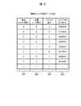
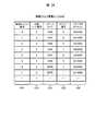
一方、ストレージ制御部ペア管理テーブル34は、容量制御部23が各ストレージ制御部ペア25の構成を管理するために利用するテーブルであり、図7に示すように、ストレージ制御部ペア番号欄34A、アクティブ側配置先ノード番号欄34B、パッシブ側配置先ノード番号欄34C、LUN欄34Dを備えて構成される。ストレージ制御部ペア管理テーブル34では、1つの行が1つのストレージ制御部ペア25に対応する。 On the other hand, the storage control unit pair management table 34 is a table used by the
そしてストレージ制御部ペア番号欄34Aには、対応するクラスタ6内に定義された各ストレージ制御部ペア25にそれぞれ付与されたそのストレージ制御部ペア25に固有の番号(ペア番号)がすべて格納される。 The storage control unit
またアクティブ側配置先ノード番号欄34Bには、対応するストレージ制御部ペア25のアクティブストレージ制御部22が配置されたストレージノード4に付与されたそのストレージノード4に固有の番号(ノード番号)が格納され、パッシブ側配置先ノード番号欄34Cには、そのストレージ制御部ペア25のパッシブストレージ制御部22が配置されたストレージノード4のノード番号が格納される。 The active-side destination
さらにLUN欄34Dには、ホスト3に提供される仮想ボリュームを識別する識別情報であるLUNが格納され、当該LUNで識別される仮想ボリュームを管理するストレージ制御部ペア番号、アクティブ側配置先ノード番号、パッシブ側配置先ノード番号と対応づけて管理される。 Further, in the
各ストレージノード4のフロントエンドドライバ20は、ホスト3からI/O要求(リード要求又はライト要求)を受領した際、I/O要求に含まれるLUNを取得し、ストレージ制御部ペア管理テーブル34を用いて当該LUNに対応付けられたストレージ制御部ペア番号、アクティブ側配置先ノード番号、パッシブ側配置先ノード番号を特定する。これにより、各ストレージノード4のフロントエンドドライバ20は、I/O要求先となる仮想ボリュームを管理するストレージ制御部ペアと、そのストレージ制御部ペアの配置先ノードを特定できる。 When receiving the I / O request (read request or write request) from the
従って、図7の例の場合、「1」というペア番号が付与されたストレージ制御部ペア25は、アクティブストレージ制御部22が「1」というノード番号が付与されたストレージノード4に配置され、パッシブストレージ制御部22が「2」というノード番号が付与されたストレージノード4に配置されていることが示されている。 Therefore, in the example of FIG. 7, the storage
物理チャンク管理テーブル35は、容量制御部23がクラスタ6内に定義された物理チャンクPCを管理するために利用するテーブルであり、図8に示すように、物理チャンク番号欄35A、所属ノード番号欄35B、ドライブ番号欄35C及びドライブ内オフセット欄35Dを備えて構成される。物理チャンク管理テーブル35では、1つの行が1つの物理チャンクPCに対応する。 The physical chunk management table 35 is a table used by the
そして物理チャンク番号欄35Aには、クラスタ6内の各物理チャンクPCにそれぞれ付与されたその物理チャンクPCに固有の番号(物理チャンク番号)がすべて格納され、所属ノード番号欄35Bには、対応する物理チャンクPCを提供するストレージノード4のノード番号が格納される。 The physical
またドライブ番号欄35Cには、対応する物理チャンクPCを提供するストレージノード4内のその物理チャンクPCを提供する記憶デバイス13に付与されたその記憶デバイス13に固有の番号(ドライブ番号)が格納される。さらにドライブ内オフセット欄35Dには、その記憶デバイス13が提供する記憶領域におけるその物理チャンクPCの当該記憶領域の先頭からのオフセット位置が格納される。 The
従って、図8の例の場合、物理チャンク番号が「0」の物理チャンクPCは、ストレージ番号が「0」のストレージノード4に搭載されたドライブ番号が「0」の記憶デバイス13における先頭から「0x00000」だけオフセットした位置から始まる所定大きさの記憶領域であることが示されている。 Therefore, in the case of the example of FIG. 8, the physical chunk PC with the physical chunk number “0” is the same as the physical chunk PC from the top of the
論理チャンク管理テーブル36は、容量制御部23がクラスタ6内に定義された論理チャンクLCを管理するために利用するテーブルであり、図9に示すように、論理チャンク番号欄36A、割当て先ストレージ制御部ペア番号欄36B、マスタ物理チャンク番号欄36C及びミラー物理チャンク番号欄36Dを備えて構成される。論理チャンク管理テーブル36では、1つの行が1つの論理チャンクLCに対応する。 The logical chunk management table 36 is a table used by the
そして論理チャンク番号欄36Aには、クラスタ6内の各論理チャンクLCにそれぞれ付与されたその論理チャンクLCに固有の番号(論理チャンク番号)が格納され、割当て先ストレージ制御部ペア番号欄36Bには、対応する論理チャンクLCが割り当てられたストレージ制御部ペア25のペア番号が格納される。 In the logical
またマスタ物理チャンク番号欄36Cには、対応する論理チャンクLCと対応付けられた複数の物理チャンクPCのうち、「マスタ」に設定された物理チャンクPCの物理チャンク番号が格納され、ミラー物理チャンク番号欄36Dには、かかる複数の物理チャンクPCのうち、「ミラー」に設定された物理チャンクPCの物理チャンク番号が格納される。 The master physical
従って、図9の例の場合、論理チャンク番号が「0」の論理チャンクLCは、ペア番号が「0」のストレージ制御部ペア25に割り当てられており、その論理チャンクLCには、「マスタ」に設定されたチャンク番号が「0」の物理チャンクPCと、「ミラー」に設定されたチャンク番号が「4」の物理チャンクPCとが対応付けられていることが示されている。 Therefore, in the example of FIG. 9, the logical chunk LC having the logical chunk number “0” is allocated to the storage
図36は、仮想ボリューム管理テーブル70の構成を示す。仮想ボリューム管理テーブル70は、各仮想ボリュームの領域と当該領域に対応付けられた論理チャンクの対応関係を管理するために利用するテーブルであり、図36に示すように、LUN欄70A、VVOLアドレス欄70B、論理チャンク番号欄70C及び論理チャンクアドレス欄70Dを備えて構成される。 FIG. 36 shows the configuration of the virtual volume management table 70. The virtual volume management table 70 is a table used to manage the correspondence between the area of each virtual volume and the logical chunk associated with the area. As shown in FIG. 36, a
LUN欄70A及びVVOLアドレス欄70Bには、ホスト3に提供される仮想ボリュームを識別する識別情報であるLUNとその仮想ボリュームのアドレス(VVOLアドレス)がそれぞれ格納され、論理チャンク番号欄70C及び論理チャンクアドレス欄70Dには、当該LUNとVVOLアドレスで識別される仮想ボリュームの領域に割り当てられた論理チャンクの論理チャンク番号と当該論理チャンクのアドレス(論理チャンクアドレス)がそれぞれ格納される。LUN欄70A、VVOLアドレス欄70B、論理チャンク番号欄70C及び論理チャンクアドレス欄70Dの情報は、仮想ボリュームの領域ごとに対応付けて管理されている。 The
VVOLアドレス欄70Bには、例えば当該仮想ボリュームの領域を示すアドレスの範囲が格納されてもよいし、又は、当該仮想ボリュームの領域の先頭アドレスが格納されてもよい。同様に、論理チャンクアドレス欄70Dには、例えば当該論理チャンクの領域を示すアドレスの範囲が格納されてもよいし、又は、当該論理チャンクの領域の先頭アドレスが格納されてもよい。 In the
各ストレージノード4のストレージ制御部22は、I/O要求(リード要求又はライト要求)を受領した際、I/O要求に含まれるLUNとVVOLアドレスを取得し、仮想ボリューム管理テーブル70を用いて当該LUN及びVVOLアドレスに対応づけられた論理チャンク番号及び論理チャンクアドレスを特定する。これにより、各ストレージノード4のストレージ制御部22は、I/O要求先となる仮想ボリュームの領域に割り当てられた論理チャンクの領域を特定できる。 When receiving the I / O request (read request or write request), the
この仮想ボリューム管理テーブル70について、例えば当該クラスタ(分散ストレージシステム)6が提供する全仮想ボリュームに関する仮想ボリューム管理テーブル70を各ノードで共有してもよいし、例えばストレージ制御部ペア25毎に、当該ストレージ制御部ペア25が提供する仮想ボリュームに関する仮想ボリューム管理テーブル70を管理してもよい。 With respect to the virtual volume management table 70, for example, the virtual volume management table 70 for all virtual volumes provided by the cluster (distributed storage system) 6 may be shared by each node. The virtual volume management table 70 relating to the virtual volumes provided by the storage
空き物理チャンク数管理テーブル37は、各ストレージノード4におけるいずれの論理チャンクLCにも未だ対応付けられていない未使用の物理チャンクPC(以下、これを空き物理チャンクPCと呼ぶ)の総数を容量制御部23が管理するために利用するテーブルであり、図10に示すように、ノード番号欄37A及び空き物理チャンク数欄37Bを備えて構成される。空き物理チャンク数管理テーブル37では、1つの行が1つのストレージノード4に対応する。 The free physical chunk number management table 37 controls the total number of unused physical chunk PCs (hereinafter referred to as free physical chunk PCs) that are not yet associated with any logical chunk LC in each
そしてノード番号欄37Aには、クラスタ6内に存在するすべてのストレージノード4のノード番号がそれぞれ格納され、空き物理チャンク数欄37Bには、対応するストレージノード4内の空物理チャンクの総数が格納される。 The
従って、図10の例の場合、ノード番号が「0」のストレージノード4には空き物理チャンクPCがなく(空き物理チャンク数が「0」)、ノード番号が「1」のストレージノード4には「10」個の空き物理チャンクPCが存在していることが示されている。 Therefore, in the example of FIG. 10, the
(1−3)ストレージノードにおいて実行される各種処理
(1−3−1)ライト処理
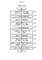
図11は、ストレージ制御部ペア25のアクティブストレージ制御部22が、当該ストレージ制御部ペア25と対応付けられた仮想ボリュームVVOLをライト対象とするライト要求を受信した場合に実行されるライト処理の流れを示す。(1-3) Various Processes Executed in Storage Node (1-3-1) Write Process FIG. 11 shows that the active
かかるライト要求をアクティブストレージ制御部22が受信すると、この図11に示すライト処理が開始され、まず、そのライト要求を受信したアクティブストレージ制御部22が、容量仮想化機能や、ローカルコピー機能及びリモートコピー機能等の必要な機能に関する必要な処理を実行する(S1)。 When the active
この後、そのアクティブストレージ制御部22は、ライト対象の仮想ボリューム(ライト対象仮想ボリューム)VVOL内の当該ライト要求において指定されたライト先領域のアドレスを、対応する論理チャンクLCのチャンク番号と、当該論理チャンクLC内の対応する論理領域のオフセット位置とに変換したI/Oコマンドを生成し(S2)、生成したI/Oコマンドを自ストレージノード4内の容量制御部23に送信する(S3)。なお、以下においては、かかるライト要求において指定されたライト対象仮想ボリュームVVOLのライト先領域に対して既に論理チャンクLCから論理領域が割り当てられているものとする。 Thereafter, the active
このI/Oコマンドを受領した容量制御部23は、ホスト装置3からのライト要求において指定されたライト対象仮想ボリュームVVOLにおけるライト先領域に論理領域を割り当てた論理チャンクLCと対応付けられているすべての物理チャンクPCをライト先物理チャンクPCとして選択する(S4)。 Upon receiving the I / O command, the
続いて、容量制御部23は、選択したライト先物理チャンクPCのいずれかが、記憶デバイス13の障害等により閉塞されている状態(以下、この状態を「閉塞中」と呼ぶ)、又は、データのコピー中(以下、これを「リビルド中」と呼ぶ)であって、かかるライト要求において指定されたライト先領域に対応する記憶デバイス13内の記憶領域へのデータコピーが未だ完了していない状態のいずれかの状態にあるか否かを判定する(S5)。Subsequently, the
そして容量制御部23は、この判定で否定結果を得るとステップS7に進む。これに対して、容量制御部23は、ステップS5の判定で肯定結果を得ると、「閉塞中」のライト先物理チャンクPC又は「リビルド中」であって、かつライト先領域に対応する記憶領域へのデータコピーが未だ完了していない物理チャンクPCをライト先物理チャンクPCから除外し(S6)、この後、ステップS7に進む。 When the
また容量制御部23は、ステップS7に進むと、物理チャンク管理テーブル35(図8)を参照して、すべてのライト先物理チャンクPCについて、それぞれそのライト先物理チャンクPCを提供する記憶デバイス13のドライブ番号と、当該記憶デバイス13におけるそのライト先物理チャンクPCのオフセット位置とを取得する(S7)。 Further, when proceeding to step S7, the
そして容量制御部23は、取得したこれらの情報に基づいて、そのときかかるアクティブストレージ制御部22がライト要求と共に受信したライトデータをすべてのライト先物理チャンクPC内の対応する記憶領域にそれぞれ格納する(S8)。以上により、このライト処理が終了する。 Then, based on the acquired information, the
(1−3−2)リード処理
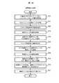
一方、図12は、ストレージ制御部ペア25のアクティブストレージ制御部22が、当該ストレージ制御部ペア25と対応付けられた仮想ボリュームVVOLをリード対象とするリード要求を受信した場合に実行される処理の流れを示す。(1-3-2) Read Process On the other hand, FIG. 12 shows that the active
かかるリード要求をアクティブストレージ制御部22が受信すると、この図12に示すリード処理が開始され、まず、そのリード要求を受信したアクティブストレージ制御部22が、容量仮想化機能や、ローカルコピー機能及びリモートコピー機能等の必要な機能に関する必要な処理を実行する(S10)。 When the active
この後、そのアクティブストレージ制御部22は、リード対象の仮想ボリューム(リード対象仮想ボリューム)VVOL内の当該リード要求において指定されたリード先領域のアドレスを、対応する論理チャンクLCのチャンク番号と、当該論理チャンクLC内の対応する論理領域のオフセット位置とに変換したI/Oコマンドを生成し(S11)、生成したI/Oコマンドを自ストレージノード4内の容量制御部23に送信する(S12)。 Thereafter, the active
このI/Oコマンドを受領した容量制御部23は、ホスト装置3からのリード要求において指定されたリード対象仮想ボリュームVVOLにおける当該リード要求において指定されたリード先領域に論理領域を割り当てた論理チャンクLCと対応付けられているすべての物理チャンクPCのうち、「マスタ」に設定されている物理チャンクPCをリード先物理チャンクPCとして選択する(S13)。 Upon receiving this I / O command, the
続いて、容量制御部23は、選択したリード先物理チャンクPCが「閉塞中」又は「リビルド中」のいずれかの状態にあるか否かを判定する(S14)。そして容量制御部23は、この判定で肯定結果を得ると、リード要求において指定されたリード対象仮想ボリュームVVOLのリード先領域に論理領域を割り当てた論理チャンクLCと対応付けられている物理チャンクPCのうち、未だステップS14の判定を行っていない物理チャンクPCを新たなリード先物理チャンクPCとして選択する(S15)。また容量制御部23は、ステップS14に戻り、この後ステップS14で否定結果を得るまでステップS14−ステップS15−ステップS14のループを繰り返す。 Subsequently, the
そして容量制御部23は、やがて条件に合致する物理チャンクPCを検出することによりステップS14で否定結果を得ると、リード先物理チャンクPCを提供する記憶デバイス13のドライブ番号と、当該記憶デバイス13におけるそのリード先物理チャンクPCのオフセット位置とを物理チャンク管理テーブル35(図8)から取得する(S16)。 When the
また容量制御部23は、取得したこれらの情報に基づいて、ホスト装置3からのリード要求において指定されたデータをその記憶デバイス13から読み出し(S17)、読み出したリードデータを、かかるI/Oコマンドの送信元のアクティブストレージ制御部22に返信した後(S18)、このリード処理を終了する。なお、このリードデータを受領したアクティブストレージ制御部22は、この後、このリードデータをリード要求の送信元のホスト装置3に転送する。 Further, based on the acquired information, the
なお、データ対象のデータがEC(Erasure Coding)により冗長データと共に複数の物理チャンクPCに分散されて格納されている場合には、容量制御部23は、上述のステップS13において、これら複数のすべての物理チャンクPCをリード先物理チャンクPCとして選択する。 When the data to be data is stored in a plurality of physical chunks PC together with redundant data by EC (Erasure Coding) and stored, the
また容量制御部23は、ステップS14において、選択したリード先物理チャンクPCの少なくとも1つが「閉塞中」又は「リビルド中」のいずれかの状態にあるか否かを判定する。そして容量制御部23は、この判定で否定結果を得た場合には、各リード先物理チャンクPCについてステップS16及びステップS17を上述と同様に実行することによりこれらリード先物理チャンクPCからデータをそれぞれ読み出す。また容量制御部23は、読み出したこれらのデータに基づいて元のデータを生成した上で、ステップS18において、生成したデータをリードデータとしてかかるI/Oコマンドの送信元のアクティブストレージ制御部22に返信し、この後、このリード処理を終了する。 In addition, in step S14, the
これに対して、容量制御部23は、ステップS14において肯定結果を得た場合には、「閉塞中」又は「リビルド中」でない残りのリード先物理チャンクPCについてステップS16及びステップS17を上述と同様に実行することにより、これらのリード先物理チャンクPCからデータをそれぞれ読み出す。また容量制御部23は、読み出したこれらのデータに基づいて、「閉塞中」又は「リビルド中」のリード先物理チャンクPCに格納されているデータを復元し、復元したデータを用いて元のデータを生成した上で、ステップS18において、生成したデータをリードデータとしてかかるI/Oコマンドの送信元のアクティブストレージ制御部22に返信し、この後、このリード処理を終了する。 On the other hand, when a positive result is obtained in step S14, the
(1−3−3)容量割当て処理
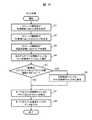
一方、図13は、同一ストレージノード4内のアクティブストレージ制御部22から、当該アクティブストレージ制御部22が属するストレージ制御部ペア25に対する最初又は追加の記憶容量(物理チャンクPC)の割当てを要求された容量制御部23の容量割当て処理部30(図5)により実行される容量割当て処理の処理手順を示す。(1-3-3) Capacity Allocation Processing On the other hand, FIG. 13 shows that the active
容量割当て処理部30は、かかる要求が与えられると、この図13に示す容量割当て処理を開始し、まず、ストレージ制御部ペア管理テーブル34(図7)を参照して、記憶容量を割当てるべきストレージ制御部ペア25(以下、これを対象ストレージ制御部ペア25と呼ぶ)を構成する各ストレージ制御部22がそれぞれ配置されたストレージノード4のノード番号をすべて取得する(S20)。 When such a request is given, the capacity
続いて、容量割当て処理部30は、対象ストレージ制御部ペア25内のアクティブストレージ制御部22が配置されたストレージノード4を優先ノードに設定する(S21)。また容量割当て処理部30は、対象ストレージ制御部ペア25内のアクティブストレージ制御部22が配置されたストレージノード4における空き物理チャンクの合計容量の下限値をアクティブ用空き容量閾値として設定する(S22)。なお、このアクティブ用空き容量閾値の値は、本情報処理システム1の設置等の際にシステム管理者などが設定する形態であっても、また予めプログラム上の定数として指定されている形態あってもよい。 Next, the capacity
次いで、容量割当て処理部30は、物理チャンク選択処理部31(図5)を呼び出し、対象ストレージ制御部ペア25に割り当てる論理チャンクLCに対応付けるべき物理チャンクPCの選択を依頼する(S23)。かくして、この依頼を受領した物理チャンク選択処理部31は、クラスタ6内の空き物理チャンクPCの中から対象ストレージ制御部ペア25の論理チャンクLCに割り当てるべき物理チャンクPCを、優先ノード(ここでは、アクティブストレージ制御部22が配置されたストレージノード4)内の空き物理チャンクPCから優先的に選択し、選択した空き物理チャンクPCのチャンク番号を容量割当て処理部30に通知する。 Next, the capacity
そして容量割当て処理部30は、かかる空き物理チャンクPCのチャンク番号が物理チャンク選択処理部31から通知されると、そのチャンク番号の物理チャンクPCを「マスタ」の物理チャンクPCとして確保する(S24)。 Then, when the chunk number of the free physical chunk PC is notified from the physical chunk
次いで、容量割当て処理部30は、対象ストレージ制御部ペア25のパッシブストレージ制御部22が配置されたストレージノード4を優先ノードに設定する(S25)。また容量割当て処理部30は、対象ストレージ制御部ペア25内のパッシブストレージ制御部22が配置されたストレージノード4における空き物理チャンクPCの合計容量の下限値をパッシブ用空き容量閾値として設定する(S26)。なお、このパッシブ用空き容量閾値の値も、本情報処理システム1の設置等の際にシステム管理者などが設定する形態であっても、また予めプログラム上の定数として指定されている形態あってもよい。 Next, the capacity
さらに容量割当て処理部30は、ステップS24で確保した、「マスタ」に設定された物理チャンクPCを提供するストレージノード4を除外ノードに設定する(S27)。 Further, the capacity
続いて、容量割当て処理部30は、物理チャンク選択処理部31(図5)を呼び出し、対象ストレージ制御部ペア25に割り当てる論理チャンクLCに対応付けるべき物理チャンクPCの選択を依頼する(S28)。かくして、この依頼を受領した物理チャンク選択処理部31は、クラスタ6内の空き物理チャンクPCの中から対象ストレージ制御部ペア25の論理チャンクLCに割り当てるべき物理チャンクPCを、優先ノード(ここでは、パッシブストレージ制御部22が配置されたストレージノード4)内の空き物理チャンクPCから優先的に選択し、選択した空き物理チャンクPCのチャンク番号を容量割当て処理部30に通知する。 Subsequently, the capacity
そして容量割当て処理部30は、かかる空き物理チャンクPCのチャンク番号が物理チャンク選択処理部31から通知されると、そのチャンク番号の物理チャンクPCを「ミラー」の物理チャンクPCとして確保する(S29)。 When notified of the chunk number of the free physical chunk PC from the physical chunk
続いて、容量割当て処理部30は、新たな論理チャンクLCを作成し、作成した論理チャンクLCに対して、ステップS24で確保した物理チャンクPCと、ステップS29で確保した物理チャンクPCとを対応付ける(S30)。また容量割当て処理部30は、ステップS30で作成した論理チャンクLCを対象ストレージ制御部ペア25のプールPLに割り当てる(S31)。 Subsequently, the capacity
そして容量割当て処理部30は、この後、この追加容量割当て処理を終了する。各ストレージノード4の容量割当て処理部30は、パッシブ用空き容量閾値とアクティブ用空き容量閾値を同じ値に設定してもよいし、異なる値に設定してもよい。また、パッシブ用空き容量閾値とアクティブ用空き容量閾値の其々について、ストレージノード4で共通の値でもよいし、ストレージノード4毎に異なる値でもよい。 Then, the capacity
ストレージノード4の容量割当て処理部30は、パッシブ用空き容量閾値をアクティブ用空き容量閾値より高い値に設定してもよい。この場合、当該ストレージノード4の空き容量がパッシブ用空き容量閾値を下回るがアクティブ用空き容量閾値を上回るとき、当該ストレージノードの記憶領域からパッシブストレージ制御部22のデータ用には新たにミラー物理チャンクの割り当てを行わないが、アクティブストレージ制御部22のデータ用には新たにマスタ物理チャンクの割り当てが可能となる。これにより、ストレージノード4において、アクティブストレージ制御部22からアクセスされるマスタ物理チャンクを、ミラー物理チャンクより優先的に割り当て可能となる。 The capacity
(1−3−4)物理チャンク選択処理
図14は、上述の容量割当て処理のステップS23及びステップS28において容量割当て処理部30から対象ストレージ制御部ペア25に割り当てる論理チャンクに対応付ける物理チャンクPCを選択するよう依頼を受けた物理チャンク選択処理部31により実行される物理チャンク選択処理の処理内容を示す。(1-3-4) Physical Chunk Selection Process FIG. 14 shows a process of selecting a physical chunk PC to be associated with a logical chunk to be allocated to the target storage
物理チャンク選択処理部31は、かかる依頼が容量割当て処理部30から与えられると、この図14に示す物理チャンク選択処理を開始し、まず、かかる依頼と共に容量割当て処理部30から通知される優先ノードのノード番号を取得する(S40)。 When such a request is given from the capacity
また物理チャンク選択処理部31は、除外ノードが設定されている場合に、かかる依頼と共に容量割当て処理部30から通知されるその除外ノードのノード番号も取得する(S41)。 When an exclusion node is set, the physical chunk
さらに物理チャンク選択処理部31は、かかる依頼と共に容量割当て処理部30から通知されるアクティブ用空き容量閾値(ステップS23の依頼の場合)、又は、パッシブ用空き容量閾値(ステップS28の依頼の場合)を取得する(S42)。 Further, the physical chunk
続いて、物理チャンク選択処理部31は、優先ノードが除外ノードではなく、かつ優先ノードに合計容量がアクティブ用空き容量閾値(ステップS23の依頼の場合)、又は、パッシブ用空き容量閾値(ステップS28の依頼の場合)以上の空き物理チャンクPCが存在するか否かを判定する(S43)。なお、この判定は、空き物理チャンク数管理テーブル37(図10)を参照して行われる。 Subsequently, the physical chunk
そして物理チャンク選択処理部31は、この判定で肯定結果を得ると、物理チャンク管理テーブル35(図8)を参照して、優先ノード内の空き物理チャンクPCの中から空き物理チャンクPCを1つ選択し(S44)、選択した空き物理チャンクPCのチャンク番号を容量割当て処理部30に通知した後(S47)、この物理チャンク選択処理を終了する。 When the physical chunk
これに対して、物理チャンク選択処理部31は、ステップS43の判定で否定結果を得ると、クラスタ6内の優先ノード及び除外ノード以外のストレージノード4の中から1つのストレージノード4を選択する(S45)。このときのストレージノード4の選択方法としては、例えば、空き物理チャンク数管理テーブル37を参照して、空き物理チャンクPCの数が最も多いストレージノード4を選択する方法を適用することができる。 On the other hand, if the physical chunk
続いて、物理チャンク選択処理部31は、ステップS45で選択したストレージノード4内の空き物理チャンクPCの中から1つの空き物理チャンクPCを選択する(S46)。また物理チャンク選択処理部31は、選択した空き物理チャンクPCのチャンク番号を容量割当て処理部30に通知し(S47)、この後、この物理チャンク選択処理を終了する。 Subsequently, the physical chunk
(1−3−5)フェイルオーバ処理
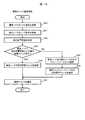
一方、図15は、容量制御部23のフェイルオーバ処理部32(図5)により定期的に実行されるフェイルオーバ処理の処理手順を示す。(1-3-5) Failover Processing On the other hand, FIG. 15 shows a processing procedure of a failover processing periodically executed by the failover processing unit 32 (FIG. 5) of the
フェイルオーバ処理部32は、このフェイルオーバ処理を開始すると、まず、クラスタ6内のすべてのストレージ制御部ペア25についてステップS51以降の処理を実行し終えたか否かを判断する(S50)。 Upon starting this failover processing, the
そしてフェイルオーバ処理部32は、この判断で否定結果を得ると、クラスタ6内の全ストレージ制御部ペア25の中からステップS51で未選択のストレージ制御部ペア25を1つ選択し(S51)、選択したストレージ制御部ペア25(以下、これを第1の選択ストレージ制御部ペア25と呼ぶ)のアクティブストレージ制御部22が配置されたストレージノード4に障害が発生しているか否かを判断する(S52)。 If the
フェイルオーバ処理部32は、この判断で否定結果を得るとステップS50に戻り、この後、第1の選択ストレージ制御部ペア25を未処理の他のストレージ制御部ペア25に順次切り替えながら、ステップS50以降の処理を繰り返す。 If the
これに対して、フェイルオーバ処理部32は、ステップS52の判断で肯定結果を得ると、第1の選択ストレージ制御部ペア25のパッシブストレージ制御部22の状態をアクティブモードに切り替え、当該ストレージ制御部ペア25のアクティブストレージ制御部22の状態をパッシブモードに切り替える(S53)。 On the other hand, when the
続いて、フェイルオーバ処理部32は、論理チャンク管理テーブル36(図9)を参照して、第1の選択ストレージ制御部ペア25に割り当てられている論理チャンクLCがあるか否かを判断する(S54)。 Subsequently, the
そしてフェイルオーバ処理部32は、この判断で否定結果を得るとステップS50に戻り、この後、第1の選択ストレージ制御部ペア25を未処理の他のストレージ制御部ペア25に順次切り替えながらステップS50以降の処理を繰り返す。 When the
これに対して、フェイルオーバ処理部32は、ステップS54の判断で肯定結果を得ると、第1の選択ストレージ制御部ペア25に割り当てられた論理チャンクLCに対応付けられている物理チャンクPCの「マスタ」及び「ミラー」の設定を切り替える(S55)。 On the other hand, when the
具体的に、フェイルオーバ処理部32は、ストレージ制御部ペア管理テーブル34(図7)における第1の選択ストレージ制御部ペア25に対応する行のアクティブ配置先ノード番号欄34B(図7)に格納されているノード番号と、その行のパッシブ配置先ノード番号欄34C(図7)に格納されているノード番号とを入れ替えるように、ストレージ制御部ペア管理テーブル34を更新する(S55)。 Specifically, the
次いで、フェイルオーバ処理部32は、ステップS50に戻り、この後、第1の選択ストレージ制御部ペア25を未処理の他のストレージ制御部ペア25に順次切り替えながらステップS50以降の処理を繰り返す。 Next, the
そしてフェイルオーバ処理部32は、やがてクラスタ6内に定義されたすべてのストレージ制御部ペア25についてステップS52以降の処理を実行し終えることによりステップS50で肯定結果を得ると、このフェイルオーバ処理を終了する。 When the
(1−3−6)再冗長化処理
他方、図16は、容量制御部23の再冗長化処理部33(図5)により定期的に実行される再冗長化処理の処理手順を示す。(1-3-6) Re-redundancy processing On the other hand, FIG. 16 shows a processing procedure of the re-redundancy processing periodically executed by the re-redundancy processing unit 33 (FIG. 5) of the
再冗長化処理部33は、この再冗長化処理を開始すると、まず、クラスタ6内のすべてのストレージ制御部ペア25についてステップS61以降の処理を実行し終えたか否かを判断する(S60)。 When starting the re-redundancy processing, the
そして再冗長化処理部33は、この判断で否定結果を得ると、クラスタ6内の全ストレージ制御部ペア25の中から未だステップS61で未選択のストレージ制御部ペア25を1つ選択し(S61)、選択したストレージ制御部ペア(以下、これを第2の選択ストレージ制御部ペアと呼ぶ)25に割り当てられているいずれかの論理チャンクLCに対応付けられたいずれかの物理チャンクPCを提供する記憶デバイス13、又は、当該記憶デバイス13が搭載されたストレージノード4に障害が発生しているか否かを判断する(S62)。 If the
再冗長化処理部33は、この判断で否定結果を得るとステップS60に戻り、この後、第2の選択ストレージ制御部ペア25を未処理の他のストレージ制御部ペア25に順次切り替えながら、ステップS60以降の処理を繰り返す。 If the
これに対して、再冗長化処理部33は、ステップS62の判断で肯定結果を得ると、かかる障害が発生したストレージノード4が提供する物理チャンク(以下、これを障害物理チャンクと呼ぶ)PCが「マスタ」に設定された物理チャンクPCであるか否かを判断する(S63)。 On the other hand, when the
そして再冗長化処理部33は、この判断で肯定結果を得ると、第2の選択ストレージ制御部ペア25のアクティブストレージ制御部22が配置されたストレージノード4を優先ノードに設定する(S64)。また再冗長化処理部33は、ステップS63の判断で否定結果を得ると、第2の選択ストレージ制御部ペア25のパッシブストレージ制御部22が配置されたストレージノード4を優先ノードに設定する(S65)。 Then, if a positive result is obtained in this determination, the
続いて、再冗長化処理部33は、第2の選択ストレージ制御部ペア25に割り当てられているいずれかの論理チャンクLCに対応付けられたいずれかの物理チャンクPCを提供するストレージノード4であって、障害が発生していないストレージノード4を除外ノードに設定する(S66)。 Subsequently, the
次いで、再冗長化処理部33は、物理チャンク選択処理部31(図5)を呼び出して図14について上述した物理チャンク選択処理を実行させることにより、ステップS62で検出した障害物理チャンクPCの代わりとなる物理チャンクPCを選択させる(S67)。 Next, the
そして再冗長化処理部33は、この後、ステップS67で物理チャンク選択処理部31により選択された物理チャンク(以下、これを被選択物理チャンクと呼ぶ)PCを、ステップS62で検出した障害物理チャンクPCに代えて第2の選択ストレージ制御部ペア25に割り当てられた対応する論理チャンク(以下、これを再冗長化対象論理チャンクと呼ぶ)LCに対応付ける(S68)。 Then, the
具体的に、再冗長化処理部33は、論理チャンク管理テーブル36(図9)における再冗長化対象論理チャンクPCに対応する行のマスタ物理チャンク番号欄36C(障害物理チャンクPCが「マスタ」の場合)又はミラー物理チャンク番号欄36D(障害物理チャンクPCが「ミラー」の場合)に格納されている障害物理チャンクPCのチャンク番号を被選択物理チャンクPCのチャンク番号に書き換える。 Specifically, the
また再冗長化処理部33は、このステップS68において、空き物理チャンク数管理テーブル37(図10)における被選択物理チャンクPCを提供するストレージノード4に対応する行の空き物理チャンク数欄37B(図10)に格納されている数値を「1」減少させた値に更新する。 In addition, in this step S68, the
さらに再冗長化処理部33は、障害物理チャンクPCが「マスタ」に設定された物理チャンクPCであった場合には、このステップS68において、障害物理チャンクPCと共に再冗長化対象論理チャンクLCに対応付けられていた物理チャンクPCであって「ミラー」に設定されていた物理チャンクPCのうち、アクティブストレージ制御部22が配置されたストレージノード4が提供する物理チャンクPCを「マスタ」に切り替える。具体的に、再冗長化処理部33は、論理チャンク管理テーブル36(図9)における再冗長化対象論理チャンクLCに対応する行のマスタ物理チャンク番号欄36C(図9)に格納されているチャンク番号と、その行のミラー物理チャンク番号欄36D(図9)に格納されているチャンク番号とを入れ替える。 Further, if the failed physical chunk PC is the physical chunk PC set to “master”, the
この後、再冗長化処理部33は、上述の被選択物理チャンクPCの状態を「リビルド中」に設定する(S69)。また再冗長化処理部33は、それまで障害物理チャンクPCに格納されていたデータをこの被選択物理チャンクPCに復元するリビルド処理を実行する(S70)。 Thereafter, the
具体的に、再冗長化処理部33は、障害物理チャンクPCに格納されていたデータが他の物理チャンクPCにミラーリングされている場合には、当該他の物理チャンクPCに格納されているデータを被選択物理チャンクPCにフルコピーする。また障害物理チャンクPCに格納されていたデータがErasure-Codingのデータの一部である場合には、そのデータを他のデータを利用して復元し、復元したデータを被選択物理チャンクPCに格納する。 Specifically, when the data stored in the failed physical chunk PC is mirrored to another physical chunk PC, the
そして再冗長化処理部33は、このリビルド処理が完了するとステップS60に戻り、この後、第2の選択ストレージ制御部ペア25を未処理の他のストレージ制御部ペア25に順次切り替えながらステップS60以降の処理を繰り返す。 When the rebuilding process is completed, the
そして再冗長化処理部33は、やがてクラスタ6内に定義されたすべてのストレージ制御部ペア25についてステップS61以降の処理を実行し終えることによりステップS60で肯定結果を得ると、この再冗長化処理を終了する。 Then, when the
(1−4)本実施の形態の効果
以上のように構成された本実施の形態の情報処理システム1では、ストレージ制御部ペア25に対して少なくとも2つの物理チャンクPCが割り当てられ、これらの物理チャンクPCにデータが二重化されて格納されるためデータが保護される。(1-4) Effects of the present embodiment In the
また本情報処理システム1では、これら2つの物理チャンクPCとして、ストレージ制御部ペア25を構成するアクティブストレージ制御部22が配置されたストレージノード4内の記憶デバイス13が提供する物理チャンクPCと、当該ストレージ制御部ペア25を構成するパッシブストレージ制御部22が配置されたストレージノード4内の記憶デバイス13が提供する物理チャンクPCとが選定される。 Further, in the
従って、かかるストレージ制御部ペア25を構成するアクティブストレージ制御部22や、アクティブモードに切り替えられたパッシブストレージ制御部22がこれらの物理チャンクPCのうちの対応する物理チャンクPCに迅速にアクセスすることができ、当該物理チャンクPCに対するデータのリード/ライトを速やかに行うことができる。 Therefore, the active
よって、本情報処理システム1によれば、システム全体としての応答性能の劣化を防止しながらデータ保護を行うことができる。 Therefore, according to the
(2)第2の実施の形態
(2−1)第2の実施の形態による情報処理システムの構成
第1の実施の形態のようにストレージ制御部ペア25に論理チャンクLCを割り当て、その論理チャンクLCに複数の物理チャンクPCを対応付けることによりデータを冗長化する場合、論理チャンクLCに対応付ける物理チャンクPCを選択するに際しては、フォールトセット(Fault Set)についても考慮することが望ましい。ここで、「フォールトセット」とは、単一の電源障害によって障害が発生するおそれがあるストレージノード4のグループを意味する。(2) Second Embodiment (2-1) Configuration of Information Processing System According to Second Embodiment As in the first embodiment, a logical chunk LC is allocated to the storage
例えば、1つのストレージノード4の障害によりデータロスト等が発生するのを防止すべく、1つの論理チャンクLCに対応付ける複数の物理チャンクPCを、それぞれ異なるストレージノード4が提供する物理チャンクPCの中から選択したとしても、これらのストレージノード4が同じ電源から電力を取得している場合には、その電源がダウンした段階でその論理チャンクLCに対応付けたすべての物理チャンクPCに対するデータのリード/ライトを行えなくなる。 For example, in order to prevent data loss or the like from occurring due to a failure of one
そこで本実施の形態においては、論理チャンクLCに複数の物理チャンクPCを対応付ける際に、フォールトセットを意識してその論理チャンクLCに対応付ける物理チャンクPCを選択する。具体的には、1つの論理チャンクLCに対応付ける物理チャンクPCとして、異なるフォールトセットに属するストレージノード4がそれぞれ提供する物理チャンクPCを選択するようにする。 Therefore, in the present embodiment, when associating a plurality of physical chunks PC with a logical chunk LC, the physical chunk PC to be associated with the logical chunk LC is selected in consideration of a fault set. Specifically, a physical chunk PC provided by each
また、このように1つの論理チャンクLCに対応付ける物理チャンクPCを異なるフォールトセットに属するストレージノード4がそれぞれ提供する物理チャンクPCを選択するようにしたとしても、かかる論理チャンクLCが割り当てられたストレージ制御部ペア25を構成する各ストレージノード4がそれぞれ配置されたストレージノード4が同じフォールトセットに属している場合には、そのフォールトセットに電源障害が発生した場合にホスト装置3からのI/O要求に対応できなくなる。 Further, even when the physical chunk PC associated with one logical chunk LC is selected from the physical chunk PCs provided by the
そこで本実施の形態においては、それぞれ異なるフォールトセットに属するストレージノード4に配置された2つのストレージ制御部22によりストレージ制御部ペア25を構成するようにする。 Therefore, in the present embodiment, a storage
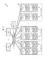
図1との対応部分に同一符号を付して示す図17は、上述のような「フォールトセット」を意識した本実施の形態による情報処理システム40の概略構成例を示す。ここでは、「ストレージノード1」及び「ストレージノード2」という2つのストレージノード41が「フォールトセット1」というフォールトセット42に属し、「ストレージノード3」及び「ストレージノード4」というストレージノード41が「フォールトセット2」というフォールトセット42に属し、……「ストレージノード(2n−1)」及び「ストレージノード2n」というストレージノード41が「フォールトセットn」というフォールトセット42に属しているものとする。FIG. 17, in which parts corresponding to those in FIG. 1 are assigned the same reference numerals, shows a schematic configuration example of an
なお各ストレージノード41のハードウェア構成は、第1の実施の形態のストレージノード4と同様であるため、ここでの説明は省略する。 Note that the hardware configuration of each
図3との対応部分に同一符号を付して示す図18は、本実施の形態の情報処理システム40に定義される各ストレージ制御部ペア25の構成例を示す。この図18に示すように、本実施の形態の場合、各ストレージ制御部ペア25は、それぞれ異なるフォールトセット42に属するストレージノード41にそれぞれ配置された2つのストレージ制御部22から構成される。 FIG. 18 in which parts corresponding to those in FIG. 3 are assigned the same reference numerals, shows a configuration example of each storage
例えば、図18の例の場合、「ストレージ制御部ペア1(SCP1)」というストレージ制御部ペア25は、「フォールトセット1」というフォールトセットに属する「ストレージノード1」というストレージノード41に配置された「ストレージ制御部1」というストレージ制御部22と、「フォールトセット2」というフォールトセットに属する「ストレージノード3」というストレージノード41に配置された「ストレージ制御部2」というストレージ制御部22とから構成されている。 For example, in the case of the example of FIG. 18, the storage
また「ストレージ制御部ペア2(SCP2)」というストレージ制御部ペア25は、「フォールトセット2」というフォールトセットに属する「ストレージノード3」というストレージノード41に配置された「ストレージ制御部3」というストレージ制御部22と、「フォールトセット1」というフォールトセットに属する「ストレージノード2」というストレージノード41に配置された「ストレージ制御部4」というストレージ制御部22とから構成されている。 Further, a storage
このような各ストレージ制御部ペア25の構成設定は、例えば、システム管理者が各ストレージノード4のフォールトセットを把握した上で管理ノード5を介して各ストレージノード4に対して行うようにしてもよい。また、いずれかのストレージノード41(例えば、クラスタ6内で代表に選出されたストレージノード41)が、図20について後述するノード管理テーブル44を参照して、異なるフォールトセット42に属するストレージノード41にそれぞれ配置された2つのストレージ制御部22からストレージ制御部ペア25を構成するようにしてもよい。Such a configuration setting of each storage
図19は、本実施の形態の情報処理システム40において、1つの論理チャンクLCに2つの物理チャンクPCを対応付ける場合の例を示す。この図19に示すように、本実施の形態の場合、1つの論理チャンクLCに対しては、互いに異なるフォールトセットに属するストレージノード41内の記憶デバイス13が提供する物理チャンクPCがそれぞれ複数対応付けられる。 FIG. 19 shows an example of a case where two physical chunks PC are associated with one logical chunk LC in the
例えば、図19の例の場合、「A」という論理チャンクLCに対しては、「フォールトセット1」というフォールトセットに属する「ストレージノード1」というストレージノード41内の記憶デバイス13が提供する「A」という物理チャンクPCと、「フォールトセット2」というフォールトセットに属する「ストレージノード3」というストレージノード41内の記憶デバイス13が提供する「A」という物理チャンクPCとが対応付けられている。For example, in the case of the example of FIG. 19, for the logical chunk “A”, “A” provided by the
また「B」という論理チャンクLCに対しては、「フォールトセット1」というフォールトセットに属する「ストレージノード1」というストレージノード41内の記憶デバイス13が提供する「B」という物理チャンクPCと、「フォールトセット2」というフォールトセットに属する「ストレージノード3」というストレージノード41内の記憶デバイス13が提供する「B」という物理チャンクPCとが対応付けられている。 For the logical chunk LC of “B”, the physical chunk PC of “B” provided by the
図20は、図6〜図10等について上述した第1の実施の形態によるフロントエンドドライバ20、バックエンドドライバ21、1又は複数のストレージ制御部22、ストレージ制御部ペア管理テーブル34、物理チャンク管理テーブル35、論理チャンク管理テーブル36及び空き物理チャンク数管理テーブル37に加えて、本実施の形態の各ストレージノード41のメモリ12(図2)に格納されるノード管理テーブル44を示す。 FIG. 20 shows the front-
ノード管理テーブル44は、各ストレージノード41がそれぞれ属するフォールトセットを管理するために本実施の形態の容量制御部43(図18)が利用するテーブルであり、図20に示すように、ノード番号欄44A及びフォールトセット番号欄44Bを備えて構成される。 The node management table 44 is a table used by the capacity control unit 43 (FIG. 18) of the present embodiment to manage the fault sets to which the
そしてノード番号欄44Aには、クラスタ6内に存在する各ストレージノード4にそれぞれ付与されたノード番号がすべて格納され、フォールトセット番号欄44Bには、対応するストレージノード4が属するフォールトセットに付与されたそのフォールトセットに固有の番号(フォールトセット番号)が格納される。 In the
従って、図20の例の場合、例えば、「1」というノード番号が付与されたストレージノード41及び「3」というノード番号が付与されたストレージノード41は、「1」というフォールトセット番号が付与されたフォールトセットに所属し、「2」というノード番号が付与されたストレージノード41及び「4」というノード番号が付与されたストレージノード41は、「2」というフォールトセット番号が付与されたフォールトセットに所属していることが示されている。 Therefore, in the case of the example of FIG. 20, for example, the
図21は、図14について上述した第1の実施の形態の容量制御部23の物理チャンク選択処理部31に代えて、本実施の形態の容量制御部43(図18)の物理チャンク選択処理部45(図5)により実行される本実施の形態による物理チャンク選択処理の処理手順を示す。なお、これ以外の容量制御部43の処理内容は第1の実施の形態の容量制御部23と同様であるため、ここでの説明は省略する。 FIG. 21 shows a physical chunk selection processing unit of the capacity control unit 43 (FIG. 18) of the present embodiment instead of the physical chunk
本実施の形態の容量制御部43の物理チャンク選択処理部45は、図13について上述した容量割当て処理のステップS23又はステップS28等において呼び出されると、この図21に示す物理チャンク選択処理を開始し、ステップS80〜ステップS83の処理を図14のステップS40〜ステップS43と同様に処理する。 The physical chunk
そして物理チャンク選択処理部45は、ステップS83の判断で肯定結果を得ると、図14について上述した容量割当て処理のステップS44及びステップS47と同様にしてステップS84及びステップS89をそれぞれ処理し、この後、この物理チャンク選択処理を終了する。 If the physical chunk
これに対して、物理チャンク選択処理部45は、ステップS83の判断で否定結果を得ると、優先ノードと同一のフォールトセットに属する他のいずれかのストレージノード41であって、当該ストレージノード41が除外ノードではなく、かつ当該ストレージノード41内に合計容量がアクティブ用空き容量閾値(ステップS23の依頼の場合)、又は、パッシブ用空き容量閾値(ステップS28の依頼の場合)以上の空き物理チャンクPCがあるストレージノード41が存在するか否かを判断する(S85)。なお、この判定は、空き物理チャンク数管理テーブル37(図10)を参照して行われる。 On the other hand, if the physical chunk
そして物理チャンク選択処理部45は、この判断で肯定結果を得ると、ステップS83の条件を満たすストレージノード41の中から1つのストレージノード41を選択する(S87)。このときのストレージノード41の選択方法としては、例えば、空き物理チャンク数管理テーブル37を参照して、ステップS85の条件を満たすストレージノード41のうち、空き物理チャンクPCの数が最も多いストレージノード41を選択する方法を適用することができる。ただし、他の方法によりストレージノード41を選択するようにしてもよい。 If the physical chunk
続いて、物理チャンク選択処理部45は、選択したストレージノード41内の空き物理チャンクPCの中から1つの空き物理チャンクPCを選択する(S88)。また物理チャンク選択処理部45は、ステップS88で選択した物理チャンクPCのチャンク番号を容量割当て処理部30(図5)に通知し(S89)、この後、この物理チャンク選択処理を終了する。 Subsequently, the physical chunk
一方、物理チャンク選択処理部45は、ステップS85の判断で否定結果を得ると、空き物理チャンク数管理テーブル37を参照して、優先ノードとは別のフォールトセットに属するいずれかのストレージノードで41あって、当該ストレージノード41が除外ノードではなく、かつ当該ストレージノード41内に合計容量がアクティブ用空き容量閾値(ステップS23の依頼の場合)、又は、パッシブ用空き容量閾値(ステップS28の依頼の場合)以上の空き物理チャンクPCがあるストレージノード41を1つ選択する(S86)。 On the other hand, if the physical chunk
また物理チャンク選択処理部45は、ステップS86で選択したストレージノード41内の空き物理チャンクPCの中から1つの空き物理チャンクを選択する(S88)。さらに物理チャンク選択処理部45は、ステップS88で選択した物理チャンクPCのチャンク番号を容量割当て処理部30に通知し(S89)、この後、この物理チャンク選択処理を終了する。 Further, the physical chunk
以上のように本実施の形態の情報処理システム40では、第1の実施の形態の構成に加えてフォールトセットをも考慮して論理チャンクLCに対応付ける物理チャンクPCを選択するようにしているため、単一の電源障害によってストレージ制御部ペア25に対応付けられたすべての物理チャンクPCに対するデータのリード/ライトが行えなくなる事態の発生を確実に回避することができる。 As described above, in the
従って、本実施の形態によれば、第1の実施の形態により得られる効果に加えて、より可用性及び信頼性の高い情報処理システムを構築することができるという効果をも得ることができる。 Therefore, according to the present embodiment, in addition to the effects obtained by the first embodiment, it is possible to obtain an effect that an information processing system with higher availability and reliability can be constructed.
(3)第3の実施の形態
図1との対応部分に同一符号を付して示す図22は、第3の実施の形態による情報処理システム50の全体構成を示す。本情報処理システム50は、階層制御機能と、これに応じた容量割当て機能とが各ストレージノード51にそれぞれ実装されている点が第1の実施の形態の情報処理システム1と相違する。本実施の形態の情報処理ステム50におけるこれ以外の機能は第1の実施の形態の情報処理システム1とほぼ同様であるため、ここでの説明は省略する。(3) Third Embodiment FIG. 22, in which parts corresponding to those in FIG. 1 are assigned the same reference numerals, shows the entire configuration of an
まず階層制御機能について説明する。階層制御機能は、記憶デバイス13が提供する記憶領域をその記憶デバイス13の応答速度に応じて複数の記憶階層(ティア:Tier)にグループ化し、よりアクセス頻度の高いデータについてはより応答速度が高い記憶階層の記憶領域に格納する機能である。 First, the hierarchical control function will be described. The tier control function groups the storage area provided by the
このため本実施の形態の場合、各ストレージノード51には、応答速度が異なる複数種類の記憶デバイス13がそれぞれ搭載され、同じ種類の記憶デバイス13が提供する物理チャンクPCが同じ記憶階層の記憶領域として管理される。 Therefore, in the case of the present embodiment, a plurality of types of
例えば、各ストレージノードにSSD、SASハードディスク装置及びSATAハードディスク装置の3種類の記憶デバイス13が搭載されている場合、最も応答速度が速いSSDが提供する物理チャンクPCが第1の記憶階層の記憶領域、次に応答速度が速いSASハードディスク装置が提供する物理チャンクPCが第2の記憶階層の記憶領域、最も応答速度が遅いSATAハードディスク装置が提供する物理チャンクPCが第3の記憶階層の記憶領域として管理される。 For example, when three types of
そして各記憶階層の記憶領域にそれぞれ格納された各データは、それぞれそのアクセス頻度が管理され、アクセス頻度が最も多いデータを第1の記憶階層の記憶領域に移動し、次にアクセス頻度が多いデータを第2の記憶階層の記憶領域に移動し、アクセス頻度が最も低いデータを第3の記憶階層の記憶領域に移動する処理が定期的に実行される。 The access frequency of each data stored in the storage area of each storage tier is managed, the data with the highest access frequency is moved to the storage area of the first storage tier, and the data with the next highest access frequency is moved. Is moved to the storage area of the second storage tier, and the process of moving the data with the lowest access frequency to the storage area of the third storage tier is periodically executed.
このような階層制御機能によれば、アクセス頻度が高いデータに対する応答性能を維持しながら、アクセス頻度が低いデータについてはコストが安い記憶デバイス13により記憶保持することができ、これによりシステム全体としてのコストを安価に抑えることができるという利点がある。 According to such a hierarchical control function, data with low access frequency can be stored and held by the low-
本実施の形態の情報処理システム50では、このような階層制御機能に対応すべく、図23に示すように、各ストレージ制御部ペア25にそれぞれ割り当てられたプールPLに対して、それぞれ異なる記憶階層の物理チャンクPCが対応付けられた複数の論理チャンクLCが割り当てられている。なお以下においては、各ストレージ制御部ペア25に3つの記憶階層(第1〜第3の記憶階層)分の論理チャンクLCをそれぞれ対応付けるものとして説明を進めるが、ストレージ制御部ペア25に対応付ける論理チャンクLCの記憶階層数は3以外であってもよい。 In order to cope with such a tier control function, the
そして各ストレージ制御部ペア25のアクティブストレージ制御部22は、自己が属するストレージ制御部ペア25と対応付けられた仮想ボリュームVVOLをライト対象仮想ボリュームVVOLとするライト要求が与えられた場合、そのライト要求において指定されたそのライト対象仮想ボリュームVVOL内のライト先領域に対して、当初は最も応答性能が高い第1の記憶階層の物理チャンクPCが対応付けられた論理チャンクLCの論理領域を割り当てる。 When the active
またアクティブストレージ制御部22は、その後、かかるライト対象仮想ボリュームVVOLにライトされた各データのアクセス頻度を監視し、これらデータに対するアクセス頻度に応じて、最もアクセス頻度が高いデータについては、仮想ボリュームVVOLにおけるそのデータがライトされた記憶領域に対応付ける論理チャンクLCの論理領域を最も高い記憶階層に属する論理チャンクLC内の論理領域に必要に応じて切り替える。またアクティブストレージ制御部22は、これに応じて、切替え後の論理チャンクLCに対応付けられた物理チャンクPC内の対応する記憶領域にそのデータを移動させる。 Further, the active
またアクティブストレージ制御部22は、次にアクセス頻度が高いデータについては、仮想ボリュームVVOLにおけるそのデータがライトされた記憶領域に対応付ける論理チャンクLCの論理領域を次に高い記憶階層に属する論理チャンクLCの論理領域に切り替え、切替え後の論理チャンクLCに対応付けられた物理チャンクPC内の対応する記憶領域にそのデータを移動させる。 Further, for data having the next highest access frequency, the active
さらにアクティブストレージ制御部22は、最もアクセス頻度が低いデータについては、仮想ボリュームVVOLにおけるそのデータがライトされた記憶領域に対応付ける論理チャンクLCの論理領域を最も低い記憶階層に属する論理チャンクLCの論理領域に切り替え、切替え後の論理チャンクLCに対応付けられた物理チャンクPCの対応する記憶領域にそのデータを移動させる。 Further, for the data with the lowest access frequency, the active
このような本実施の形態の容量割当て機能を実現するための手段として、本実施の形態の各ストレージノード51のメモリ12(図2)には、図8について上述した物理チャンク管理テーブル35に代えて図24に示す物理チャンク管理テーブル52が格納されると共に、図9について上述した論理チャンク管理テーブル36に代えて図25に示す論理チャンク管理テーブル53が格納され、さらに図10について上述した空き物理チャンク数管理テーブル37に代えて図26に示す空き物理チャンク数管理テーブル54が格納されている。 As means for realizing such a capacity allocation function of the present embodiment, the memory 12 (FIG. 2) of each
そして本実施の形態の物理チャンク管理テーブル52には、図8について上述した物理チャンク管理テーブル35の物理チャンク番号欄35A、所属ノード番号欄35B、ドライブ番号欄35C及びドライブ内オフセット欄35Dとそれぞれ同様の情報が格納される物理チャンク番号欄52A、所属ノード番号欄52B、ドライブ番号欄52D及びドライブ内オフセット欄52Eに加えて、メディアタイプ欄52Cが設けられている。そしてメディアタイプ欄52Cには、対応する物理チャンクPCを提供する記憶デバイス13のメディアタイプ(SSD、SAS又はSATAなど)が格納される。 The physical chunk management table 52 according to the present embodiment is the same as the physical
従って、図24の例の場合、物理チャンク番号が「0」〜「2」、「4」又は「5」の物理チャンクPCはメディアタイプが「SSD」の記憶デバイス13が提供する物理チャンクであり、物理チャンク番号が「3」の物理チャンクPCはメディアタイプが「SAS」の記憶デバイス13が提供する物理チャンクであり、物理チャンク番号が「6」及び「7」の物理チャンクPCはメディアタイプが「SATA」の記憶デバイス13が提供する物理チャンクであることが示されている。 Therefore, in the case of the example of FIG. 24, the physical chunk PCs whose physical chunk numbers are “0” to “2”, “4”, or “5” are physical chunks provided by the
また本実施の形態の論理チャンク管理テーブル53には、図9について上述した論理チャンク管理テーブル36の論理チャンク番号欄36A、割当て先ストレージ制御部ペア番号欄36B、マスタ物理チャンク番号欄36C及びミラー物理チャンク番号欄36Dとそれぞれ同様の情報が格納される論理チャンク番号欄53A、割当て先ストレージ制御部ペア番号欄53B、マスタ物理チャンク番号欄53D及びミラー物理チャンク番号欄53Eに加えて、メディアタイプ欄53Cが設けられている。そしてメディアタイプ欄53Cには、対応する論理チャンクLCに対応付けられた物理チャンクPCを提供する記憶デバイス13のメディアタイプが格納される。 In the logical chunk management table 53 of the present embodiment, the logical
従って、図25の例の場合、論理チャンク番号が「0」又は「1」の論理チャンクLCは、いずれもメディアタイプが「SSD」の記憶デバイス13が提供する物理チャンクPCが対応付けられた論理チャンクであり、論理チャンク番号が「2」の論理チャンクLCは、メディアタイプが「SAS」の記憶デバイス13が提供する物理チャンクPCが対応付けられた論理チャンクであることが示されている。 Therefore, in the case of the example of FIG. 25, the logical chunk LC having the logical chunk number “0” or “1” is the logical chunk associated with the physical chunk PC provided by the
さらに本実施の形態の空き物理チャンク数管理テーブル54には、図10について上述した空き物理チャンク数管理テーブル37のノード番号欄37A及び空き物理チャンク数欄37Bとそれぞれ同様の情報が格納されるノード番号欄54A及び空き物理チャンク数欄54Bに加えて、各記憶階層にそれぞれ対応させた空き物理チャンク数欄54C,54D,54Eが設けられている。そして、これら空き物理チャンク数欄54C〜54Eには、それぞれ対応する記憶階層を構成するメディアタイプの記憶デバイス13が提供する物理チャンクPCのうちの空き物理チャンクPCの数が格納される。 Further, in the free physical chunk number management table 54 according to the present embodiment, nodes storing the same information as the
従って、図26の例の場合、例えば、ノード番号が「1」のストレージノード51内には、現時点において、第1の記憶階層を構成する「SSD」というメディアタイプの記憶デバイス13が提供する空き物理チャンクPCが「5」つ存在し、第2の記憶階層を構成する「SAS」というメディアタイプの記憶デバイス13が提供する空き物理チャンクPCが「2」つ存在し、第3の記憶階層を構成する「SATA」というメディアタイプの記憶デバイス13が提供する空き物理チャンクPCが「3」つ存在することが示されている。なお、上述のようにどのメディアタイプの記憶デバイス13がどの記憶階層に属するかは予め定められているものとする。 Therefore, in the case of the example of FIG. 26, for example, in the
図5との対応部分に同一符号を付して示す図27は、本実施の形態の容量制御部55の構成を示す。本実施の形態の容量制御部55は、容量割当て処理部56及び物理チャンク選択処理部57の処理内容が異なる点を除いて、第1の実施の形態の容量制御部23(図5)と同様に構成されている。 FIG. 27 in which parts corresponding to those in FIG. 5 are assigned the same reference numerals, shows the configuration of a
図28は、同じストレージノード51内のアクティブストレージ制御部22から、当該アクティブストレージ制御部22が属するストレージ制御部ペア25に対する最初又は追加の記憶容量の割当てを要求された本実施の形態の容量制御部55の容量割当て処理部56(図27)により実行される容量割当て処理の処理手順を示す。なお本実施の形態の場合、アクティブストレージ制御部22は、記憶階層を指定して記憶容量の割当てを容量制御部55に要求する。 FIG. 28 illustrates the capacity control according to the present embodiment in which the active
容量割当て処理部56は、かかる要求が与えられると、この図28に示す容量割当て処理を開始し、まず、指定された記憶階層を確認し(S90)、この後、ステップS91〜ステップS93を図13について上述した第1の実施の形態の容量割当て処理のステップS20〜ステップS22と同様に処理する。 When such a request is given, the capacity
続いて、容量割当て処理部56は、物理チャンク選択処理部57(図27)を呼び出し、ステップS90で確認した対象ストレージ制御部ペア25に割り当てる記憶階層の論理チャンクLCに対応付けるべき物理チャンクPCの選択を依頼する(S94)。かくして、この依頼を受領した物理チャンク選択処理部57は、クラスタ6内の空き物理チャンクPCの中から対象ストレージ制御部ペア25の指定された記憶階層の論理チャンクLCに割り当てるべき物理チャンクPCを、優先ノード(ここでは、アクティブストレージ制御部22が配置されたストレージノード51)内の空き物理チャンクPCから優先的に選択し、選択した空き物理チャンクPCのチャンク番号を容量割当て処理部56に通知する。 Subsequently, the capacity
次いで、容量割当て処理部56は、ステップS95〜ステップS98を、図13について上述した第1の実施の形態の容量割当て処理のステップS24〜ステップS27と同様に処理する。また容量割当て処理部56は、この後、物理チャンク選択処理部57(図27)を呼び出し、ステップS90で確認した対象ストレージ制御部ペア25に割り当てる記憶階層の論理チャンクLCに対応付けるべき物理チャンクPCの選択を依頼する(S99)。かくして、この依頼を受領した物理チャンク選択処理部57は、クラスタ6内の空き物理チャンクPCの中から対象ストレージ制御部ペア25の指定された記憶階層の論理チャンクLCに割り当てるべき物理チャンクPCを、優先ノード(ここでは、パッシブストレージ制御部22が配置されたストレージノード51)内の空き物理チャンクPCから優先的に選択し、選択した空き物理チャンクPCのチャンク番号を容量割当て処理部56に通知する。 Next, the capacity
続いて、容量割当て処理部56は、ステップS100〜ステップS102を、図13について上述した容量割当て処理のステップS29〜ステップS31と同様に処理し、この後、この容量割当て処理を終了する。 Subsequently, the capacity
他方、図29は、図28について上述した本実施の形態の容量割当て処理のステップS94又はステップS99において容量割当て処理部56から対象ストレージ制御部ペア25に割り当てる論理チャンクLCに対応付ける物理チャンクPCを選択するよう依頼を受けた物理チャンク選択処理部57により実行される物理チャンク選択処理の処理内容を示す。 On the other hand, FIG. 29 shows that the physical allocation chunk PC to be associated with the logical chunk LC to be allocated to the target storage
物理チャンク選択処理部57は、かかる依頼が容量割当て処理部56から与えられると、この図29に示す物理チャンク選択処理を開始し、まず、ステップS110〜ステップS112を図14について上述した第1の実施の形態の物理チャンク選択処理のステップS40〜ステップS42と同様に処理する。 When such a request is given from the capacity
続いて、物理チャンク選択処理部57は、優先ノードが除外ノードではなく、かつ優先ノード内の指定された階層の記憶デバイスに合計容量がアクティブ用空き容量閾値(ステップS93の依頼の場合)、又は、パッシブ用空き容量閾値(ステップS99の依頼の場合)以上の空き物理チャンクPCが存在するか否かを判定する(S113)。なお、この判定は、空き物理チャンク数管理テーブル54(図26)を参照して行われる。 Subsequently, the physical chunk
そして物理チャンク選択処理部57は、この判定で肯定結果を得ると、物理チャンク管理テーブル52(図24)を参照して、優先ノード内の指定された記憶階層の記憶デバイス13が提供する空き物理チャンクPCの中から空き物理チャンクPCを1つ選択し(S114)、選択した空き物理チャンクPCのチャンク番号を容量割当て処理部56に通知した後(S117)、この物理チャンク選択処理を終了する。 When the physical chunk
これに対して、物理チャンク選択処理部57は、ステップS113の判定で否定結果を得ると、クラスタ6内の優先ノード及び除外ノード以外のストレージノード51の中から1つのストレージノード51を選択する(S115)。このときのストレージノード51の選択方法としては、例えば、空き物理チャンク数管理テーブル37を参照して、指定された記憶階層の記憶デバイス13が提供する物理チャンクPCのうちの空き物理チャンクPCの数が最も多いストレージノード51を選択する方法を適用することができる。ただし、他の方法によりストレージノード51を選択するようにしてもよい。 On the other hand, if the physical chunk
続いて、物理チャンク選択処理部57は、ステップS115で選択したストレージノード51内の指定された記憶階層の記憶デバイス13が提供する空き物理チャンクPCの中から1つの空き物理チャンクPCを選択する(S116)。また物理チャンク選択処理部57は、選択した空き物理チャンクPCのチャンク番号を容量割当て処理部56に通知し(S117)、この後、この物理チャンク選択処理を終了する。 Subsequently, the physical chunk
以上のように本実施の形態によれば、階層制御機能が搭載された情報処理システム50についても第1の実施の形態と同様の効果を得ることができる。 As described above, according to the present embodiment, the same effect as that of the first embodiment can be obtained for the
(4)他の実施の形態
なお上述の第1〜第3の実施の形態においては、図1、図17及び図22のように、ホスト装置に物理的な記憶領域を提供する記憶デバイス13を各ストレージノード4,41,51に搭載するようにした場合について述べたが、本発明はこれに限らず、例えば、図1との対応部分に同一符号を付した図30に示すように、かかる記憶デバイス13を各ストレージノード60に搭載せず、これらストレージノード60にかかる記憶デバイス13が搭載された外部ストレージ装置61を接続するようにしてもよい。(4) Other Embodiments In the first to third embodiments, as shown in FIGS. 1, 17, and 22, the
この場合、各ストレージノード60のハードウェア構成は、図2から記憶デバイス13を除去した構成とし、これら各ストレージノード60の論理構成は、図3について構成したストレージノード4の論理構成と同様とすればよい。なお、このようにした場合におけるフロントエンドドライバ20、バックエンドドライバ21、ストレージ制御部22及び容量制御部23の制御内容は、第1の実施の形態と同様である。 In this case, the hardware configuration of each
従って、この例の場合、各ストレージ制御部ペア25に対しては、そのストレージ制御部ペア25を構成するアクティブストレージ制御部22が配置されたストレージノード60と接続された外部ストレージ装置61に搭載された記憶デバイス13が提供する物理チャンクPCと、当該ストレージ制御部ペア25を構成するパッシブストレージ制御部22が配置されたストレージノード60と接続された外部ストレージ装置61に搭載された記憶デバイス13が提供する物理チャンクPCとが対応付けられた論理チャンクLCが割り当てられることになる。 Therefore, in the case of this example, each storage
また上述の第1〜第3の実施の形態においては、図14について上述した物理チャンク選択処理のステップS45及びS46や、図21について上述した物理チャンク選択処理のステップS87及びS88、並びに、図29について上述した物理チャンク選択処理のステップS115及びS116において、空き物理チャンクPCの数が最も多いストレージノード4内の空き物理チャンクPCの中からストレージ制御部ペア25に割り当てる論理チャンクLCに対応付ける物理チャンクPCを選択するようにした場合について述べたが、本発明はこれに限らず、ストレージ制御部ペア25を構成するアクティブストレージ制御部22やパッシブストレージ制御部22の配置先近傍の物理チャンクPCを優先的にそのストレージ制御部ペア25に割り当てる論理チャンクLCに対応付けるようにしてもよい。 In the first to third embodiments described above, steps S45 and S46 of the physical chunk selection process described above with reference to FIG. 14, steps S87 and S88 of the physical chunk selection process described above with reference to FIG. In steps S115 and S116 of the physical chunk selection process described above, the physical chunk PC associated with the logical chunk LC to be allocated to the storage
なお「ストレージ制御部22の配置先近傍の物理チャンクPC」とは、そのストレージ制御部22がその物理チャンクPCにアクセスする際に経由するスイッチ等のネットワークデバイスが少ない物理チャンクPCを指す。従って、ストレージ制御部22の配置先の最も近傍の物理チャンクPCは、そのストレージ制御部22が配置されたストレージノード4内の物理チャンクPCということになる。 The “physical chunk PC near the storage destination of the
このようにストレージ制御部ペア25を構成するアクティブストレージ制御部22やパッシブストレージ制御部22の配置先近傍の物理チャンクPCを優先的にそのストレージ制御部ペア25に割り当てる論理チャンクLCに対応付けるようにしても、アクティブストレージ制御部22やパッシブストレージ制御部22が迅速にその物理チャンクPCにアクセスすることができ、当該物理チャンクPCに対するデータのリード/ライトを速やかに行うことができる。 In this manner, the physical chunk PC near the placement destination of the active
さらに上述の第1の実施の形態においては、図13及び図14について上述したように、ストレージ制御部ペア25のアクティブストレージ制御部22が配置されたストレージノード4や、当該ストレージ制御部ペア25のパッシブストレージ制御部22が配置されたストレージノード4を優先ノードに設定(図13のステップS21及びステップS25を参照)することにより、物理チャンク選択処理部31がこれらのストレージノード4の空き物理チャンクPCを優先的にそのストレージ制御部ペア25に割り当てる論理チャンクLCに対応付ける物理チャンクPCとして選択するようにした場合について述べたが、本発明はこれに限らず、物理チャンク選択処理部31が、クラスタ6内の各ストレージノード4の空き物理チャンクPCの数にのみ基づいてかかる論理チャンクLCに対応付ける空き物理チャンクPCを選択するようにしてもよい。 Further, in the above-described first embodiment, as described above with reference to FIGS. 13 and 14, the
具体的には、図13との対応部分に同一符号を付した図31に示すように、容量割当て処理部30が、図13のステップS21及びステップS25を省略することにより、対象ストレージ制御部ペア25のアクティブストレージ制御部22や、パッシブストレージ制御部22が配置されたストレージノード4を優先ノードに設定しないようにする。また図14との対応部分に同一符号を付した図32に示すように、物理チャンク選択処理部31が、ステップS42の後で優先ノードが設定されているか否かを判定し(S120)、否定結果を得た場合にはステップS43に進み、肯定結果を得た場合にはステップS45に進むようにすればよい。 Specifically, as shown in FIG. 31 in which the same reference numerals are given to the corresponding parts in FIG. 13, the capacity
ただし、ストレージ制御部ペア25に割り当てる論理チャンクLCに対応付ける物理チャンクPCとして、そのストレージ制御部ペア25のアクティブストレージ制御部22が配置されたストレージノード4内の空き物理チャンクPCを選択した方が通常時におけるシステム全体としての応答性能が良いため、図13との対応部分に同一符号を付した図33に示すように、ステップS21については実行し、図13のステップS25については処理を省略するように容量割当て処理部30を構成するようにしてもよい。この場合においても、図32のフローチャートの処理を実行するように物理チャンク選択処理部31を構築すればよい。 However, it is usually preferable to select an empty physical chunk PC in the
さらに上述の第3の実施の形態においては、図28及び図29について上述したように、容量制御部55(図27)の容量割当て処理部56(図27)が、すべての階層について、ストレージ制御部ペア25のアクティブストレージ制御部22が配置されたストレージノード4や、当該ストレージ制御部ペア25のパッシブストレージ制御部22が配置されたストレージノード4を優先ノードに設定(図13のステップS21及びステップS25を参照)することにより、物理チャンク選択処理部57(図27)がこれらのストレージノード4の空き物理チャンクPCを優先的にそのストレージ制御部ペア25に割り当てる論理チャンクLCに対応付ける物理チャンクPCとして選択するようにした場合について述べたが、本発明はこれに限らず、指定された記憶階層が最上位の記憶階層のときにのみ、物理チャンク選択処理部57が、クラスタ6内の各ストレージノード4の空き物理チャンクPCの数にのみ基づいてかかる論理チャンクLCに対応付ける空き物理チャンクPCを選択するようにしてもよい。 Further, in the third embodiment, as described above with reference to FIGS. 28 and 29, the capacity allocation processing unit 56 (FIG. 27) of the capacity control unit 55 (FIG. 27) performs storage control for all tiers. The
この場合、図28との対応部分に同一符号を付した図34に示すように、容量割当て処理部56は、ステップS91の処理実行後にステップS90で確認した記憶階層が最上位の記憶階層であるか否かを判断し(S130)し、否定結果を得た場合には対象ストレージ制御部ペア25内のアクティブストレージ制御部22が配置されたストレージノード4を優先ノードに設定することなくステップS93に進む。また容量割当て処理部56は、ステップS95の処理実行後にステップS90で確認した記憶階層が最上位の記憶階層であるか否かを判断し(S131)し、否定結果を得た場合には対象ストレージ制御部ペア25内のアクティブストレージ制御部22が配置されたストレージノード4を優先ノードに設定することなくステップS97に進む。 In this case, as shown in FIG. 34 in which the same reference numerals are given to the parts corresponding to FIG. 28, the storage tier confirmed in step S90 after execution of the processing in step S91 is the highest storage tier. It is determined whether or not the
また、この場合、図29との対応部分に同一符号を付した図35に示すように、物理チャンク選択処理部31は、ステップS112の後で優先ノードが設定されているか否かを判定し(S132)、否定結果を得た場合にはステップS115に進み、肯定結果を得た場合にはステップS114に進むようにすればよい。 In this case, as shown in FIG. 35 in which the same reference numerals are given to the corresponding parts in FIG. 29, the physical chunk
このようにすることにより、応答性能が要求される最上位の記憶階層については、自ノードから記憶領域を割り当て、これ以外の記憶階層については、各ストレージノード4から均等に記憶領域を割り当てることができる。 By doing so, the storage area is allocated from the own node for the highest storage tier that requires response performance, and the storage areas are equally allocated from each
また、サーバ上でハイパーバイザが動作し、ハイパーバイザ上で1又は複数の仮想計算機が稼働し、その仮想計算機上で、図3に示す各種プログラムが動作してもよい。すなわち、各種プログラム(制御ソフト20、冗長化部22、クラスタ制御部23)は、物理計算機のハードウェア上で動作することもあれば、仮想計算機上で動作してもよい。同様に、コンピュートノード2は、仮想計算機上で動作するアプリケーションプログラム(ホストプログラム)であってもよいし、物理的なホスト計算機(ホストコンピュータ)であってもよい。情報処理システム1が複数のサーバを有するとき、サーバの一部が異なるサイトにあってもよい。また、情報処理システム1のサーバの一部又は全部がクラウド上にあって、ネットワークを介して、ユーザにサービスが提供されてもよい。 Alternatively, a hypervisor may operate on the server, one or a plurality of virtual machines may operate on the hypervisor, and various programs illustrated in FIG. 3 may operate on the virtual machines. That is, the various programs (the
各種プログラム(制御ソフト20、冗長化部22、クラスタ制御部23)が動作する仮想計算機と、ホストプログラムが動作する仮想計算機とが、同一のサーバ(ノード)上にある構成(ハイパーコンバージドインフラストラクチャ)であっても、ネットワークを介して接続する異なるサーバ上にある構成であってもよい。 A configuration in which a virtual machine on which various programs (control
本発明は、1又は複数のSDSが実装された複数のストレージノードを備える情報処理システムに適用することができる。 The present invention can be applied to an information processing system including a plurality of storage nodes on which one or a plurality of SDSs are mounted.
1,40,50……情報処理システム、3……ホスト装置、4,41,51,60……ストレージノード、6……クラスタ、11……CPU、13……記憶デバイス、22……ストレージ制御部、23,43,55……容量制御部、25……ストレージ制御部ペア、30,56……容量割当て処理部、31,45,57……物理チャンク選択処理部、32……フェイルオーバ処理部、33……再冗長化処理部、34……ストレージ制御部ペア管理テーブル、35,52……物理チャンク管理テーブル、36,53……論理チャンク管理テーブル、37,54……空き物理チャンク数管理テーブル、42……フォールトセット、44……ノード管理テーブル、61……外部ストレージ装置、LC……論理チャンク、LP……プール、PC……物理チャンク、VVOL……仮想ボリューム。 1, 40, 50 ... information processing system, 3 ... host device, 4, 41, 51, 60 ... storage node, 6 ... cluster, 11 ... CPU, 13 ... storage device, 22 ... storage control , 23, 43, 55 ... capacity control unit, 25 ... storage control unit pair, 30, 56 ... capacity allocation processing unit, 31, 45, 57 ... physical chunk selection processing unit, 32 ... failover processing unit , 33 ... re-redundancy processing unit, 34 ... storage control unit pair management table, 35, 52 ... physical chunk management table, 36, 53 ... logical chunk management table, 37, 54 ... free physical chunk number management Table, 42: Fault set, 44: Node management table, 61: External storage device, LC: Logical chunk, LP: Pool, PC: Object Chunk, VVOL ...... virtual volume.
Claims (14)
Translated fromJapanese各々の前記ストレージノードは、
クラスタ内の複数の前記ストレージノードの各記憶デバイスがそれぞれ提供する容量を管理する容量制御部と、
I/O要求を受け付け、受け付けた前記I/O要求に応じたコマンドを生成して前記容量制御部に送信するストレージ制御部と、
を備え、
前記記憶システムは、
それぞれ異なる前記ストレージノードに配置された複数の前記ストレージ制御部が、ストレージ制御部グループを構成し、
前記ストレージ制御部グループの第1の前記ストレージ制御部が前記I/O要求を処理する第1の状態に設定されると共に、前記ストレージ制御部グループの第2の前記ストレージ制御部が当該I/O要求を処理しない第2の状態に設定され、
前記記憶デバイスに格納されるデータを、異なるストレージノードに格納される複数のデータを組みにしてデータ冗長化しており、
前記容量制御部は、
前記ストレージ制御部が属するノード及び他のストレージノードの物理記憶領域を前記ストレージ制御部グループに割り当てることが可能であり、
他のストレージノードの前記物理記憶領域を前記ストレージ制御部グループに割り当てる場合に、前記データ冗長化したデータの組みの他のデータと同じストレージノードに格納されないように前記他のストレージノードを選択して割り当てる
ことを特徴とする記憶システム。In a storage system having a plurality of storage nodes,
Each of the storage nodes is
A capacity control section in which a plurality of the storage devicesof the storage nodesin the cluster to manage thecapacity to provide, respectively,
Receiving anI / O request, a storage control unit which generates a corresponding to the I / O request accepted command transmitted to the capacity control unit,
With
The storage system comprises:
The storage control unit of themultiple arranged in said different storage nodes respectively,constitutes a storage control unitgroup,
Together with thefirst of the storage control unitof the storage control unitgroup is set to a first statefor processing thepre-SL I / O request,the second of the storage control unitof the storage control unit group the I / O is set to a second statethat does not process the request,
The data stored in the storage device is data redundant by combining a plurality of data stored in different storage nodes,
The capacity control unit includes:
It is possible to assign a physical storage area of the node to which the storage control unit belongs and another storage node to the storage control unit group,
When assigning the physical storage area of another storage node to the storage control unit group, selecting the other storage node so as not to be stored in the same storage node as the other data of the data redundant data set A storage system characterized byassigning .
前記データ冗長化は、同じデータを複数のストレージノードに格納することにより行うThe data redundancy is performed by storing the same data in a plurality of storage nodes.
ことを特徴とする記憶システム。A storage system, characterized in that:
前記データ冗長化により、少なくとも1の同一のデータについて、前記第1のストレージ制御部が配置されるストレージノードの物理記憶領域及び前記第2のストレージ制御部が配置されるストレージノードの物理記憶領域の両方に格納されているDue to the data redundancy, for at least one and the same data, the physical storage area of the storage node where the first storage control unit is located and the physical storage area of the storage node where the second storage control unit is located Stored in both
ことを特徴とする記憶システム。A storage system, characterized in that:
前記データ冗長化は、前記データから冗長コードを生成して、前記データが格納されるノードとは異なるストレージノードに前記冗長コードを格納することにより行うThe data redundancy is performed by generating a redundant code from the data and storing the redundant code in a storage node different from a node where the data is stored.
ことを特徴とする記憶システム。A storage system, characterized in that:
第1の前記ストレージ制御部グループの第1のストレージ制御部は、第2の前記ストレージ制御部グループの第2のストレージ制御部と同じストレージノードに配置され、A first storage controller of the first storage controller group is located on the same storage node as a second storage controller of the second storage controller group;
前記第1のストレージ制御部グループの第2のストレージ制御部は、第3の前記ストレージ制御部グループの第1のストレージ制御部と同じストレージノードに配置されるThe second storage controller of the first storage controller group is located on the same storage node as the first storage controller of the third storage controller group.
ことを特徴とする記憶システム。A storage system, characterized in that:
前記ストレージ制御部が配置された前記ストレージノード内に予め設定された閾値以上の空き容量がある場合には、当該ストレージ制御部が属する前記ストレージ制御部グループに対して、当該ストレージノードが提供する前記物理記憶領域を割り当て、
前記ストレージ制御部が配置された前記ストレージノードに前記閾値以上の空き容量がない場合には、当該ストレージ制御部が属する前記ストレージ制御部グループに対して、当該ストレージ制御部が配置されていない前記ストレージノードに搭載された前記記憶デバイスが提供する前記物理記憶領域を割り当てる
ことを特徴とする請求項1に記載の記憶システム。The capacity control unit includes:
Ifthe previous SL storage control unit there is a free space of more than a presetthreshold valueto arrangedin the storage node, to the storage control unitgroup to which the storage control unit belongs,it is the storagenode provided Assigning the physical storage area to
If no free space above the thresholdbefore Symbol the storagenode by the storage control unit is disposed, with respect to the storage control unitgroup to which the storage control unit belongs, the storage control unit is not arranged storage system according to claim1, characterized in that assigning the physical storage area in which the storage device mountedin the storagenode is provided.
同じデータを、前記ストレージ制御部グループを有する複数のストレージノードに格納することにより行っており、
前記容量制御部は、
前記ストレージ制御部が配置された前記ストレージノード内に閾値以上の空き容量がない場合には、当該ストレージ制御部が属する前記ストレージ制御部グループに対して、当該ストレージ制御部グループのいずれの前記ストレージ制御部も配置されていない前記ストレージノードが提供する前記物理記憶領域を割り当てる
ことを特徴とする請求項6に記載の記憶システム。The data redundancy,
By storing the same data in a plurality of storage nodes having the storage control unit group,
The capacity control unit includes:
If no threshold value or more free spaceinfront Symbol storage controllerin the storage node disposed, with respect to the storage control unitgroup to which the storage controller belongs, all of the storage of the storage control unitgroup storage system of claim6, wherein the storagenodes also control unit is notdisposed and allocates the physical storage area provided.
前記ストレージ制御部グループを構成する複数の前記ストレージ制御部のうち、前記第1の状態に設定された前記ストレージ制御部の配置先のストレージノードの前記物理記憶領域をマスタに設定する
ことを特徴とする請求項7に記載の記憶システム。The capacity control unit includes:
And setting, as a master, the physical storage area ofa storage node to which the storage control unit set to the first state is located, among aplurality of storage control units constituting the storage control unitgroup. The storage system according to claim7 , wherein:
前記ストレージ制御部グループを構成する複数の前記ストレージ制御部のうち、前記第2の状態に設定された前記ストレージ制御部の状態が前記第1の状態に切り替えられたときには、当該ストレージ制御部グループに割り当てた前記物理記憶領域のうち、当該第1の状態に切り替えられた前記ストレージ制御部の配置先のストレージノードの前記物理記憶領域を前記マスタに切り替える
ことを特徴とする請求項8に記載の記憶システム。The capacity control unit includes:
Wherein among theplurality of the storage control unit which constitutes a storage control unitgroup, the when the second state which is set to a of the storage controller state is switched to the first state, to the storage control unitgroup 9. The storage according to claim8 , wherein, among the allocated physical storage areas, the physical storage area ofa storage node where the storage control unit has been switched to the first state and which is the destinationof the storage control unit is switched to the master. 10. system.
前記ストレージ制御部グループを構成する各前記ストレージ制御部は、それぞれ異なるフォールトセットに属する前記ストレージノードに配置され、
前記容量制御部は、
前記ストレージ制御部グループに対して、当該ストレージ制御部グループを構成するいずれかの前記ストレージ制御部と同じ前記フォールトセットに属する前記ストレージノードが提供する前記物理記憶領域を対応付ける
ことを特徴とする請求項1に記載の記憶システム。One or more of the storage nodes whose failures arepropagated by a single failure are managed as a fault set;
Each of the storage control units constituting the storage control unitgroup is arranged in the storage node belonging to a different fault set,
The capacity control unit includes:
To the storage control unitgroup, and wherein the attaching the physical storagearea corresponds to the storagenode is provided belonging to the same the fault set as either the storage control unit that constitute the storage control unitgroup The storage system according to claim1 , wherein:
前記2つのストレージノードは、前記第1のストレージ制御部と同じフォールトセットに属するストレージノードと、前記第2のストレージ制御部と同じフォールトセットに属するストレージノードと、の組み合わせであるThe two storage nodes are a combination of a storage node belonging to the same fault set as the first storage control unit and a storage node belonging to the same fault set as the second storage control unit.
ことを特徴とする請求項10に記載の記憶システム。The storage system according to claim 10, wherein:
前記ストレージ制御部グループには、前記物理記憶領域が各種類の前記記憶デバイスごとに割り当てられる
ことを特徴とする請求項1に記載の記憶システム。Each said storagenodes, each response speed is mounted different types of the storage device,
The storage system according to claim 1,wherein the physical storage area isallocated to each type of the storage devices in the storage control unitgroup .
各々の前記ストレージノードは、
クラスタ内の複数の前記ストレージノードの各記憶デバイスがそれぞれ提供する容量を管理する容量制御部と、
I/O要求を受け付け、受け付けた前記I/O要求に応じたコマンドを生成して前記容量制御部に送信するストレージ制御部と、
を有し、
前記記憶システムは、
それぞれ異なる前記ストレージノードに配置された複数の前記ストレージ制御部がストレージ制御部グループを構成し、
前記ストレージ制御部グループの第1の前記ストレージ制御部が前記I/O要求を受け付ける第1の状態に設定されると共に、前記ストレージ制御部グループの第2の前記ストレージ制御部が当該I/O要求を処理しない第2の状態に設定され、
前記記憶デバイスに格納されるデータを、異なるストレージノードに格納される複数のデータを組みにしてデータ冗長化しており、
前記容量制御部は、
前記ストレージ制御部が属するノード及び他のノードの物理記憶領域を前記ストレージ制御部グループに割り当てることが可能であり、
他のノードの前記物理記憶領域を前記ストレージ制御部に割り当てる場合に、前記データ冗長化したデータの組みの他のデータと同じノードに格納されないように前記他のノードを選択して割り当てる
ことを特徴とする制御方法。A method for controlling a storage system having a plurality of storage nodes,
Each of the storage nodes is
A capacity control unit that manages the capacity provided by each storage deviceof the plurality of storage nodesin the cluster ,
Receiving anI / O request, a storage control unit which generates a corresponding to the I / O request accepted command transmitted to the capacity control unit,
Has,
The storage system comprises:
A plurality of storage control units arranged in different storage nodes respectivelyconstitute a storage control unitgroup ,
Together with thefirst of the storage control unitof the storage control unitgroup is set to a first statethat acceptspre SL I / O request,the second of the storage control unitof the storage control unit group the I / O Set to a second statethat does not process the request,
The data stored in the storage device is data redundant by combining a plurality of data stored in different storage nodes,
The capacity control unitincludes :
It is possible to assign a physical storage area of a node to which the storage control unit belongs and another node to the storage control unit group,
When allocating the physical storage area of another node to the storage control unit, the other node is selected and allocated soas not to be stored in the same node as other data of the data redundant data set. And control method.
各々の前記ストレージノードは、Each of the storage nodes is
クラスタ内の複数の前記ストレージノードの各記憶デバイスがそれぞれ提供する容量を管理する容量制御部と、A capacity control unit that manages the capacity provided by each storage device of the plurality of storage nodes in the cluster,
I/O要求を受け付け、受け付けた前記I/O要求に応じたコマンドを生成して前記容量制御部に送信するストレージ制御部と、A storage control unit that receives an I / O request, generates a command corresponding to the received I / O request, and transmits the command to the capacity control unit;
を備え、With
前記記憶システムは、The storage system comprises:
それぞれ異なる前記ストレージノードに配置された複数の前記ストレージ制御部が、ストレージ制御部グループを構成し、A plurality of storage control units arranged in different storage nodes respectively constitute a storage control unit group,
前記ストレージ制御部グループの第1の前記ストレージ制御部が前記I/O要求を処理する第1の状態に設定されると共に、前記ストレージ制御部グループの第2の前記ストレージ制御部が当該I/O要求を処理しない第2の状態に設定され、The first storage control unit of the storage control unit group is set to a first state of processing the I / O request, and the second storage control unit of the storage control unit group is set to the I / O request. Set to a second state that does not process the request,
前記記憶デバイスに格納されるデータを、マスタデータ及びスレーブデータを組みにしてデータ冗長化しており、The data stored in the storage device is data redundancy by combining master data and slave data,
前記容量制御部は、The capacity control unit includes:
前記ストレージ制御部が属するノード及び他のストレージノードの物理記憶領域を前記ストレージ制御部グループに割り当てることが可能であり、It is possible to assign a physical storage area of the node to which the storage control unit belongs and another storage node to the storage control unit group,
前記マスタデータは、前記第1の状態のストレージ制御部が配置されたストレージノードを含む第1のストレージノードグループの物理記憶領域に格納され、前記スレーブデータは、前記第2の状態のストレージ制御部が配置されたストレージノードを含む第2のストレージノードグループの物理記憶領域に格納され、The master data is stored in a physical storage area of a first storage node group including a storage node in which the storage controller in the first state is arranged, and the slave data is stored in a storage controller in the second state. Is stored in the physical storage area of the second storage node group including the storage node where
前記スレーブデータを格納するストレージノードの前記物理記憶領域を前記ストレージ制御部グループに割り当てる場合に、前記マスタデータを格納する第1のストレージノードグループのストレージノードに格納されないように前記ストレージノードを選択して割り当てるWhen allocating the physical storage area of the storage node that stores the slave data to the storage control unit group, select the storage node so that the storage node is not stored in the storage node of the first storage node group that stores the master data. Assign
ことを特徴とする記憶システム。A storage system, characterized in that:
Priority Applications (5)
| Application Number | Priority Date | Filing Date | Title |
|---|---|---|---|
| JP2017231219AJP6668309B2 (en) | 2017-11-30 | 2017-11-30 | Storage system and control method thereof |
| US15/910,085US10282136B1 (en) | 2017-11-30 | 2018-03-02 | Storage system and control method thereof |
| CN201810972792.7ACN109857334B (en) | 2017-11-30 | 2018-08-24 | Storage system and control method thereof |
| US16/377,372US11137940B2 (en) | 2017-11-30 | 2019-04-08 | Storage system and control method thereof |
| JP2020031069AJP6905611B2 (en) | 2017-11-30 | 2020-02-26 | Storage system and its control method |
Applications Claiming Priority (1)
| Application Number | Priority Date | Filing Date | Title |
|---|---|---|---|
| JP2017231219AJP6668309B2 (en) | 2017-11-30 | 2017-11-30 | Storage system and control method thereof |
Related Child Applications (1)
| Application Number | Title | Priority Date | Filing Date |
|---|---|---|---|
| JP2020031069ADivisionJP6905611B2 (en) | 2017-11-30 | 2020-02-26 | Storage system and its control method |
Publications (2)
| Publication Number | Publication Date |
|---|---|
| JP2019101702A JP2019101702A (en) | 2019-06-24 |
| JP6668309B2true JP6668309B2 (en) | 2020-03-18 |
Family
ID=66333818
Family Applications (1)
| Application Number | Title | Priority Date | Filing Date |
|---|---|---|---|
| JP2017231219AActiveJP6668309B2 (en) | 2017-11-30 | 2017-11-30 | Storage system and control method thereof |
Country Status (3)
| Country | Link |
|---|---|
| US (2) | US10282136B1 (en) |
| JP (1) | JP6668309B2 (en) |
| CN (1) | CN109857334B (en) |
Cited By (1)
| Publication number | Priority date | Publication date | Assignee | Title |
|---|---|---|---|---|
| US12099726B2 (en) | 2022-02-16 | 2024-09-24 | Hitachi, Ltd. | Rebalancing volumes in computer system comprising upper and lower cluster |
Families Citing this family (13)
| Publication number | Priority date | Publication date | Assignee | Title |
|---|---|---|---|---|
| JP6547057B2 (en)* | 2016-02-22 | 2019-07-17 | 株式会社日立製作所 | Computer system, computer system control method, and recording medium |
| JP6905611B2 (en)* | 2017-11-30 | 2021-07-21 | 株式会社日立製作所 | Storage system and its control method |
| US11169746B2 (en)* | 2018-06-19 | 2021-11-09 | Weka.IO LTD | Expanding a distributed storage system |
| JP6857673B2 (en)* | 2019-02-14 | 2021-04-14 | 株式会社日立製作所 | Capacity management method for multi-storage node system and multi-storage node system |
| JP7050034B2 (en)* | 2019-07-29 | 2022-04-07 | 株式会社日立製作所 | Storage system and node management method |
| CN110781129B (en)* | 2019-09-12 | 2022-02-22 | 苏州浪潮智能科技有限公司 | Resource scheduling method, device and medium in FPGA heterogeneous accelerator card cluster |
| CN111124316B (en)* | 2019-12-30 | 2023-12-19 | 青岛海尔科技有限公司 | Storage space sharing method and device and computer-readable storage medium |
| US11734093B2 (en)* | 2020-06-23 | 2023-08-22 | Samsung Electronics Co., Ltd. | Storage device block-level failure prediction-based data placement |
| CN112148904B (en)* | 2020-07-31 | 2021-07-27 | 中标慧安信息技术股份有限公司 | Indexing method and device for alarm linkage video |
| JP7149313B2 (en)* | 2020-09-28 | 2022-10-06 | 株式会社日立製作所 | Storage system and its control method |
| US11803318B2 (en)* | 2021-04-21 | 2023-10-31 | EMC IP Holding Company LLC | Active-passive configuration for synchronous remote replication in an active-active metro cluster |
| JP7590316B2 (en)* | 2021-12-23 | 2024-11-26 | 日立ヴァンタラ株式会社 | Information processing system and configuration management method |
| CN114691698B (en)* | 2022-04-24 | 2022-11-08 | 山西中汇数智科技有限公司 | Data processing system and method for computer system |
Family Cites Families (16)
| Publication number | Priority date | Publication date | Assignee | Title |
|---|---|---|---|---|
| US6446175B1 (en)* | 1999-07-28 | 2002-09-03 | Storage Technology Corporation | Storing and retrieving data on tape backup system located at remote storage system site |
| US7010553B2 (en)* | 2002-03-19 | 2006-03-07 | Network Appliance, Inc. | System and method for redirecting access to a remote mirrored snapshot |
| EP1546929A4 (en)* | 2002-09-18 | 2008-07-02 | Netezza Corp | Intelligent storage device controller |
| WO2004114116A1 (en)* | 2003-06-19 | 2004-12-29 | Fujitsu Limited | Method for write back from mirror cache in cache duplicating method |
| US7971025B2 (en)* | 2007-03-14 | 2011-06-28 | Hitachi, Ltd. | Method and apparatus for chunk allocation in a thin provisioning storage system |
| JP4386932B2 (en)* | 2007-08-17 | 2009-12-16 | 富士通株式会社 | Storage management program, storage management device, and storage management method |
| US8335899B1 (en)* | 2008-03-31 | 2012-12-18 | Emc Corporation | Active/active remote synchronous mirroring |
| JP5217967B2 (en)* | 2008-11-28 | 2013-06-19 | 富士通株式会社 | Failure node separation processing program, failure node separation method, and storage system |
| US8356147B2 (en) | 2010-08-20 | 2013-01-15 | Hitachi, Ltd. | Tiered storage pool management and control for loosely coupled multiple storage environment |
| US8984243B1 (en)* | 2013-02-22 | 2015-03-17 | Amazon Technologies, Inc. | Managing operational parameters for electronic resources |
| JP6135226B2 (en)* | 2013-03-21 | 2017-05-31 | 日本電気株式会社 | Information processing apparatus, information processing method, storage system, and computer program |
| US9323463B2 (en)* | 2014-08-05 | 2016-04-26 | Hitachi, Ltd. | Storage system and cache control method |
| JP6536160B2 (en)* | 2015-04-30 | 2019-07-03 | 富士通株式会社 | Storage system, control device and control program |
| JP6569477B2 (en)* | 2015-11-02 | 2019-09-04 | 富士通株式会社 | Storage control device and control program |
| US10379973B2 (en)* | 2015-12-28 | 2019-08-13 | Red Hat, Inc. | Allocating storage in a distributed storage system |
| WO2017149674A1 (en)* | 2016-03-01 | 2017-09-08 | 株式会社日立製作所 | Storage system, storage device, and storage system control method |
- 2017
- 2017-11-30JPJP2017231219Apatent/JP6668309B2/enactiveActive
- 2018
- 2018-03-02USUS15/910,085patent/US10282136B1/enactiveActive
- 2018-08-24CNCN201810972792.7Apatent/CN109857334B/enactiveActive
- 2019
- 2019-04-08USUS16/377,372patent/US11137940B2/enactiveActive
Cited By (1)
| Publication number | Priority date | Publication date | Assignee | Title |
|---|---|---|---|---|
| US12099726B2 (en) | 2022-02-16 | 2024-09-24 | Hitachi, Ltd. | Rebalancing volumes in computer system comprising upper and lower cluster |
Also Published As
| Publication number | Publication date |
|---|---|
| CN109857334A (en) | 2019-06-07 |
| US11137940B2 (en) | 2021-10-05 |
| US10282136B1 (en) | 2019-05-07 |
| US20190163395A1 (en) | 2019-05-30 |
| US20190235792A1 (en) | 2019-08-01 |
| CN109857334B (en) | 2022-04-29 |
| JP2019101702A (en) | 2019-06-24 |
Similar Documents
| Publication | Publication Date | Title |
|---|---|---|
| JP6668309B2 (en) | Storage system and control method thereof | |
| JP6791834B2 (en) | Storage system and control software placement method | |
| JP6814764B2 (en) | Information processing system and path management method | |
| US11068367B2 (en) | Storage system and storage system control method | |
| US10082972B2 (en) | Method and system for pooling, partitioning, and sharing network storage resources | |
| JP4890033B2 (en) | Storage device system and storage control method | |
| CN109857335B (en) | System, control method thereof, and storage medium | |
| JP5124551B2 (en) | Computer system for managing volume allocation and volume allocation management method | |
| JP2021012476A (en) | Distributed storage system, control method and storage medium of distributed storage system | |
| JP7167078B2 (en) | Distributed storage system and storage control method | |
| JP2021135703A (en) | Information processing system and method | |
| JP2014219787A (en) | Storage system, control program of information processor, and method for controlling storage system | |
| JP2020047215A (en) | Storage system and storage control method | |
| JP7419456B2 (en) | Storage system and its control method | |
| JP6961045B2 (en) | System and its control method and program | |
| JP2008210031A (en) | Storage area management method for storage system | |
| JP7506707B2 (en) | Storage system and failure handling method | |
| JP7057408B2 (en) | Storage system and its control method | |
| JP6905611B2 (en) | Storage system and its control method | |
| JP7592063B2 (en) | Information processing system and information processing method | |
| JP2023151189A (en) | Storage system and method for controlling the same | |
| JP7193602B2 (en) | System and its control method and program | |
| JP2024172391A (en) | STORAGE CONTROLLER AND METHOD FOR CONTROLLING STORAGE CONTROLLER | |
| WO2017017775A1 (en) | Computer system and volume allocation control method |
Legal Events
| Date | Code | Title | Description |
|---|---|---|---|
| A521 | Request for written amendment filed | Free format text:JAPANESE INTERMEDIATE CODE: A523 Effective date:20190227 | |
| A621 | Written request for application examination | Free format text:JAPANESE INTERMEDIATE CODE: A621 Effective date:20190227 | |
| A977 | Report on retrieval | Free format text:JAPANESE INTERMEDIATE CODE: A971007 Effective date:20191226 | |
| TRDD | Decision of grant or rejection written | ||
| A01 | Written decision to grant a patent or to grant a registration (utility model) | Free format text:JAPANESE INTERMEDIATE CODE: A01 Effective date:20200128 | |
| A61 | First payment of annual fees (during grant procedure) | Free format text:JAPANESE INTERMEDIATE CODE: A61 Effective date:20200226 | |
| R150 | Certificate of patent or registration of utility model | Ref document number:6668309 Country of ref document:JP Free format text:JAPANESE INTERMEDIATE CODE: R150 | |
| S111 | Request for change of ownership or part of ownership | Free format text:JAPANESE INTERMEDIATE CODE: R313111 | |
| R350 | Written notification of registration of transfer | Free format text:JAPANESE INTERMEDIATE CODE: R350 |