JP6667449B2 - Humidifier for respiratory therapy device - Google Patents
Humidifier for respiratory therapy deviceDownload PDFInfo
- Publication number
- JP6667449B2 JP6667449B2JP2016557038AJP2016557038AJP6667449B2JP 6667449 B2JP6667449 B2JP 6667449B2JP 2016557038 AJP2016557038 AJP 2016557038AJP 2016557038 AJP2016557038 AJP 2016557038AJP 6667449 B2JP6667449 B2JP 6667449B2
- Authority
- JP
- Japan
- Prior art keywords
- humidifier
- wick
- water
- air
- algorithm
- Prior art date
- Legal status (The legal status is an assumption and is not a legal conclusion. Google has not performed a legal analysis and makes no representation as to the accuracy of the status listed.)
- Active
Links
Images


Classifications
- A—HUMAN NECESSITIES
- A61—MEDICAL OR VETERINARY SCIENCE; HYGIENE
- A61M—DEVICES FOR INTRODUCING MEDIA INTO, OR ONTO, THE BODY; DEVICES FOR TRANSDUCING BODY MEDIA OR FOR TAKING MEDIA FROM THE BODY; DEVICES FOR PRODUCING OR ENDING SLEEP OR STUPOR
- A61M16/00—Devices for influencing the respiratory system of patients by gas treatment, e.g. ventilators; Tracheal tubes
- A61M16/10—Preparation of respiratory gases or vapours
- A61M16/14—Preparation of respiratory gases or vapours by mixing different fluids, one of them being in a liquid phase
- A61M16/16—Devices to humidify the respiration air
- A—HUMAN NECESSITIES
- A61—MEDICAL OR VETERINARY SCIENCE; HYGIENE
- A61M—DEVICES FOR INTRODUCING MEDIA INTO, OR ONTO, THE BODY; DEVICES FOR TRANSDUCING BODY MEDIA OR FOR TAKING MEDIA FROM THE BODY; DEVICES FOR PRODUCING OR ENDING SLEEP OR STUPOR
- A61M16/00—Devices for influencing the respiratory system of patients by gas treatment, e.g. ventilators; Tracheal tubes
- A61M16/021—Devices for influencing the respiratory system of patients by gas treatment, e.g. ventilators; Tracheal tubes operated by electrical means
- A61M16/022—Control means therefor
- A61M16/024—Control means therefor including calculation means, e.g. using a processor
- A61M16/026—Control means therefor including calculation means, e.g. using a processor specially adapted for predicting, e.g. for determining an information representative of a flow limitation during a ventilation cycle by using a root square technique or a regression analysis
- A—HUMAN NECESSITIES
- A61—MEDICAL OR VETERINARY SCIENCE; HYGIENE
- A61M—DEVICES FOR INTRODUCING MEDIA INTO, OR ONTO, THE BODY; DEVICES FOR TRANSDUCING BODY MEDIA OR FOR TAKING MEDIA FROM THE BODY; DEVICES FOR PRODUCING OR ENDING SLEEP OR STUPOR
- A61M16/00—Devices for influencing the respiratory system of patients by gas treatment, e.g. ventilators; Tracheal tubes
- A61M16/06—Respiratory or anaesthetic masks
- A—HUMAN NECESSITIES
- A61—MEDICAL OR VETERINARY SCIENCE; HYGIENE
- A61M—DEVICES FOR INTRODUCING MEDIA INTO, OR ONTO, THE BODY; DEVICES FOR TRANSDUCING BODY MEDIA OR FOR TAKING MEDIA FROM THE BODY; DEVICES FOR PRODUCING OR ENDING SLEEP OR STUPOR
- A61M16/00—Devices for influencing the respiratory system of patients by gas treatment, e.g. ventilators; Tracheal tubes
- A61M16/10—Preparation of respiratory gases or vapours
- A61M16/1075—Preparation of respiratory gases or vapours by influencing the temperature
- A61M16/109—Preparation of respiratory gases or vapours by influencing the temperature the humidifying liquid or the beneficial agent
- A—HUMAN NECESSITIES
- A61—MEDICAL OR VETERINARY SCIENCE; HYGIENE
- A61M—DEVICES FOR INTRODUCING MEDIA INTO, OR ONTO, THE BODY; DEVICES FOR TRANSDUCING BODY MEDIA OR FOR TAKING MEDIA FROM THE BODY; DEVICES FOR PRODUCING OR ENDING SLEEP OR STUPOR
- A61M16/00—Devices for influencing the respiratory system of patients by gas treatment, e.g. ventilators; Tracheal tubes
- A61M16/10—Preparation of respiratory gases or vapours
- A61M16/14—Preparation of respiratory gases or vapours by mixing different fluids, one of them being in a liquid phase
- A61M16/142—Preparation of respiratory gases or vapours by mixing different fluids, one of them being in a liquid phase with semi-permeable walls separating the liquid from the respiratory gas
- A—HUMAN NECESSITIES
- A61—MEDICAL OR VETERINARY SCIENCE; HYGIENE
- A61M—DEVICES FOR INTRODUCING MEDIA INTO, OR ONTO, THE BODY; DEVICES FOR TRANSDUCING BODY MEDIA OR FOR TAKING MEDIA FROM THE BODY; DEVICES FOR PRODUCING OR ENDING SLEEP OR STUPOR
- A61M11/00—Sprayers or atomisers specially adapted for therapeutic purposes
- A61M11/04—Sprayers or atomisers specially adapted for therapeutic purposes operated by the vapour pressure of the liquid to be sprayed or atomised
- A61M11/041—Sprayers or atomisers specially adapted for therapeutic purposes operated by the vapour pressure of the liquid to be sprayed or atomised using heaters
- A61M11/042—Sprayers or atomisers specially adapted for therapeutic purposes operated by the vapour pressure of the liquid to be sprayed or atomised using heaters electrical
- A61M11/044—Sprayers or atomisers specially adapted for therapeutic purposes operated by the vapour pressure of the liquid to be sprayed or atomised using heaters electrical with electrodes immersed in the liquid
- A—HUMAN NECESSITIES
- A61—MEDICAL OR VETERINARY SCIENCE; HYGIENE
- A61M—DEVICES FOR INTRODUCING MEDIA INTO, OR ONTO, THE BODY; DEVICES FOR TRANSDUCING BODY MEDIA OR FOR TAKING MEDIA FROM THE BODY; DEVICES FOR PRODUCING OR ENDING SLEEP OR STUPOR
- A61M16/00—Devices for influencing the respiratory system of patients by gas treatment, e.g. ventilators; Tracheal tubes
- A61M16/10—Preparation of respiratory gases or vapours
- A61M16/105—Filters
- A61M16/1055—Filters bacterial
- A—HUMAN NECESSITIES
- A61—MEDICAL OR VETERINARY SCIENCE; HYGIENE
- A61M—DEVICES FOR INTRODUCING MEDIA INTO, OR ONTO, THE BODY; DEVICES FOR TRANSDUCING BODY MEDIA OR FOR TAKING MEDIA FROM THE BODY; DEVICES FOR PRODUCING OR ENDING SLEEP OR STUPOR
- A61M16/00—Devices for influencing the respiratory system of patients by gas treatment, e.g. ventilators; Tracheal tubes
- A61M16/10—Preparation of respiratory gases or vapours
- A61M16/105—Filters
- A61M16/106—Filters in a path
- A61M16/107—Filters in a path in the inspiratory path
- A—HUMAN NECESSITIES
- A61—MEDICAL OR VETERINARY SCIENCE; HYGIENE
- A61M—DEVICES FOR INTRODUCING MEDIA INTO, OR ONTO, THE BODY; DEVICES FOR TRANSDUCING BODY MEDIA OR FOR TAKING MEDIA FROM THE BODY; DEVICES FOR PRODUCING OR ENDING SLEEP OR STUPOR
- A61M16/00—Devices for influencing the respiratory system of patients by gas treatment, e.g. ventilators; Tracheal tubes
- A61M16/10—Preparation of respiratory gases or vapours
- A61M16/14—Preparation of respiratory gases or vapours by mixing different fluids, one of them being in a liquid phase
- A61M16/16—Devices to humidify the respiration air
- A61M16/161—Devices to humidify the respiration air with means for measuring the humidity
- A—HUMAN NECESSITIES
- A61—MEDICAL OR VETERINARY SCIENCE; HYGIENE
- A61M—DEVICES FOR INTRODUCING MEDIA INTO, OR ONTO, THE BODY; DEVICES FOR TRANSDUCING BODY MEDIA OR FOR TAKING MEDIA FROM THE BODY; DEVICES FOR PRODUCING OR ENDING SLEEP OR STUPOR
- A61M2205/00—General characteristics of the apparatus
- A61M2205/33—Controlling, regulating or measuring
- A61M2205/3368—Temperature
- A—HUMAN NECESSITIES
- A61—MEDICAL OR VETERINARY SCIENCE; HYGIENE
- A61M—DEVICES FOR INTRODUCING MEDIA INTO, OR ONTO, THE BODY; DEVICES FOR TRANSDUCING BODY MEDIA OR FOR TAKING MEDIA FROM THE BODY; DEVICES FOR PRODUCING OR ENDING SLEEP OR STUPOR
- A61M2205/00—General characteristics of the apparatus
- A61M2205/33—Controlling, regulating or measuring
- A61M2205/3379—Masses, volumes, levels of fluids in reservoirs, flow rates
- A61M2205/3389—Continuous level detection
- A—HUMAN NECESSITIES
- A61—MEDICAL OR VETERINARY SCIENCE; HYGIENE
- A61M—DEVICES FOR INTRODUCING MEDIA INTO, OR ONTO, THE BODY; DEVICES FOR TRANSDUCING BODY MEDIA OR FOR TAKING MEDIA FROM THE BODY; DEVICES FOR PRODUCING OR ENDING SLEEP OR STUPOR
- A61M2205/00—General characteristics of the apparatus
- A61M2205/60—General characteristics of the apparatus with identification means
- A61M2205/6018—General characteristics of the apparatus with identification means providing set-up signals for the apparatus configuration
- A—HUMAN NECESSITIES
- A61—MEDICAL OR VETERINARY SCIENCE; HYGIENE
- A61M—DEVICES FOR INTRODUCING MEDIA INTO, OR ONTO, THE BODY; DEVICES FOR TRANSDUCING BODY MEDIA OR FOR TAKING MEDIA FROM THE BODY; DEVICES FOR PRODUCING OR ENDING SLEEP OR STUPOR
- A61M2205/00—General characteristics of the apparatus
- A61M2205/70—General characteristics of the apparatus with testing or calibration facilities
- A61M2205/707—Testing of filters for clogging
- A—HUMAN NECESSITIES
- A61—MEDICAL OR VETERINARY SCIENCE; HYGIENE
- A61M—DEVICES FOR INTRODUCING MEDIA INTO, OR ONTO, THE BODY; DEVICES FOR TRANSDUCING BODY MEDIA OR FOR TAKING MEDIA FROM THE BODY; DEVICES FOR PRODUCING OR ENDING SLEEP OR STUPOR
- A61M2206/00—Characteristics of a physical parameter; associated device therefor
- A61M2206/10—Flow characteristics
- A61M2206/14—Static flow deviators in tubes disturbing laminar flow in tubes, e.g. archimedes screws
Landscapes
- Health & Medical Sciences (AREA)
- Emergency Medicine (AREA)
- Pulmonology (AREA)
- Engineering & Computer Science (AREA)
- Anesthesiology (AREA)
- Biomedical Technology (AREA)
- Heart & Thoracic Surgery (AREA)
- Hematology (AREA)
- Life Sciences & Earth Sciences (AREA)
- Animal Behavior & Ethology (AREA)
- General Health & Medical Sciences (AREA)
- Public Health (AREA)
- Veterinary Medicine (AREA)
- Air Humidification (AREA)
- Air Conditioning Control Device (AREA)
- Respiratory Apparatuses And Protective Means (AREA)
Description
Translated fromJapanese本技術は、呼吸器関連疾患の検出、診断、治療、予防および改善の1つまたはそれ以上に関する。特に本技術は医療機器または装置およびそれらの使用に関する。 The present technology relates to one or more of detecting, diagnosing, treating, preventing and ameliorating a respiratory related disease. In particular, the technology relates to medical devices or devices and their uses.
[関連出願の相互参照]
この出願は、2014年3月13日に出願されたオーストラリア国仮出願番号AU2014900869、2014年3月24日に出願されたAU2014901035、2014年11月11日に出願されたAU2014904513の利益をクレームするもので、その全開示を参照により本明細書に包含する。[Cross-reference of related applications]
This application claims the benefit of Australian provisional application number AU2014900869 filed on March 13, 2014, AU2014901035 filed on March 24, 2014, and AU2014904513 filed on November 11, 2014. , The entire disclosure of which is hereby incorporated by reference.
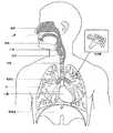
2.2.1 ヒト呼吸器系
身体の呼吸器系はガス交換を促進する。鼻と口が患者の気道の入口を形成する。2.2.1 The human respiratory system The body's respiratory system facilitates gas exchange. The nose and mouth form the entrance to the patient's airway.
気道は一連の枝管を含み、それらは肺に深く入るにつれて狭く、短くそしておびただしくなる。肺の主要機能はガス交換であり、酸素は空気から静脈血に入り、二酸化炭素が運び出される。気管は左右の主気管支に分かれ、さらに分岐して最後に終末細気管支となる。気管支は誘導気道を構成し、ガス交換には関与しない。気道をさらに分割すると呼吸細気管支となり、最終的に肺胞となる。ガス交換が行われる肺の胞状の領域は、呼吸領域と呼ばれる。非特許文献1を参照。 The respiratory tract contains a series of branches, which become narrow, short and crowded as they penetrate deep into the lungs. The main function of the lungs is gas exchange, oxygen enters the venous blood from the air, and carbon dioxide is carried away. The trachea is divided into left and right main bronchi, which further diverges to finally end bronchioles. The bronchi make up the conducting airways and are not involved in gas exchange. When the airway is further divided, it becomes respiratory bronchioles, which eventually become alveoli. The alveolar area of the lung where gas exchange takes place is called the respiratory area. See Non-Patent
一連の呼吸器疾患が存在する。 There is a range of respiratory diseases.
閉塞性睡眠時無呼吸(OSA)は睡眠呼吸障害(SDB)の1つで、睡眠時の上部気道の閉鎖または閉塞が特徴である。これは異常に小さい上気道と、舌の領域の筋緊張の通常の喪失、睡眠時の軟口蓋および後口咽頭壁の正常損失の組み合わせの結果である。この条件で罹患患者は典型的には30から120秒の間呼吸が停止し、場合によっては一晩で200から300回呼吸停止が起こる。昼間に過剰な眠気を生じることがたびたびあり、これは心臓血管疾患と脳損傷を起こすことがある。この症候群は特に太りすぎの中年男性に共通する障害であるが、罹患者はこの問題に気付いていないことがる。特許文献1(Sullivan)を参照。 Obstructive sleep apnea (OSA) is a form of sleep-disordered breathing (SDB) that is characterized by closure or obstruction of the upper airway during sleep. This is the result of a combination of an abnormally small upper respiratory tract and the normal loss of muscle tone in the area of the tongue, the normal loss of the soft palate and posterior oropharyngeal wall during sleep. In this condition, the affected patient typically stops breathing for 30 to 120 seconds, and occasionally 200 to 300 breath holds overnight. Excessive sleepiness often occurs during the day, which can cause cardiovascular disease and brain damage. The syndrome is a common disorder, especially among overweight middle-aged men, but affected individuals may not be aware of the problem. See U.S. Pat.
チェーン・ストークス呼吸(CSR)は患者の呼吸調整器の障害で、この場合呼吸の漸増と漸減が交互に律動的に生じ、動脈血の脱酸素化と再酸素化が繰り返し生じる。反復低酸素症のため、CSRは有害であり得る。患者によってはCSRは睡眠中の反復覚醒に関連しており、これは重篤な睡眠障害、交感神経系活動の増悪および後負荷の増加を生じる。特許文献2(Berthon-Jones)を参照。 Cheyne-Stokes respiration (CSR) is a disorder of the patient's respiratory regulator, in which the respiration and gradual rise and fall of breathing alternate and pulsatile, resulting in repeated deoxygenation and reoxygenation of arterial blood. CSR can be harmful because of recurrent hypoxia. In some patients, CSR has been associated with repetitive wakefulness during sleep, which results in severe sleep disturbances, increased sympathetic nervous system activity, and increased afterload. See Patent Document 2 (Berthon-Jones).
肥満過呼吸症候群(OHS)は、低呼吸の既知の原因がない場合、重症の肥満と覚醒時慢性高炭酸ガス血症の組み合わせと定義される。症状には呼吸困難、起床時の頭痛と過剰な日中の眠気が含まれる。 Obesity hyperpnea syndrome (OHS) is defined as a combination of severe obesity and awake chronic hypercapnia when there is no known cause of hypopnea. Symptoms include dyspnea, headache on waking, and excessive daytime sleepiness.
慢性閉塞性肺疾患(COPD)は、共通してある特徴を有する下気道疾患の任意のグループを含む。これには空気の動きに対する抵抗の増加、呼吸の呼気相の延長および肺における正常な弾性の減少が含まれる。COPDの例は肺気腫と慢性気管支炎である。COPDは常時喫煙(第一危険因子)、職業的暴露、大気汚染および遺伝因子で発症する。症状には、労作時呼吸困難、慢性咳および痰が出ることが含まれる。 Chronic obstructive pulmonary disease (COPD) includes any group of lower respiratory tract diseases that share some characteristics. This includes increased resistance to air movement, prolonged expiratory phase of breathing, and decreased normal elasticity in the lungs. Examples of COPD are emphysema and chronic bronchitis. COPD is caused by constant smoking (first risk factor), occupational exposure, air pollution and genetic factors. Symptoms include dyspnea on exertion, chronic cough and sputum.
神経筋疾患(NMD)は、内在筋肉病変を経て直接的に、または神経病変を経て間接的に筋肉の機能を損なう多くの疾病と病気を包含する広義語である。NMD患者の一部は、歩行の喪失にいたる進行性筋障害が特徴で、車椅子に束縛され、嚥下障害があり、呼吸筋力低下を生じ最後には呼吸不全により死に至る。神経筋疾患は急速進行性と緩徐進行性に分けられる:(i) 急速進行性疾患は数か月にわたる筋肉の機能障害があり、数年以内に死に至るのが特徴である(例: 筋萎縮性側索硬化症(ALS)と10代のデュシェンヌ型筋ジストロフィー(DMD));(ii)可変または緩徐進行性疾患:数年にわたって増悪し、平均寿命を少し短縮するのが特徴である(例:肢帯、顔面肩甲上腕型筋ジストロフィーおよび筋強直性ジストロフィー)。NMDにおける呼吸不全の症候には、全身衰弱の進行、嚥下障害、労作時および安静時呼吸困難、疲労、眠気、起床時の頭痛、集中することの困難および気分転換の困難が含まれる。 Neuromuscular disease (NMD) is a broad term that encompasses many diseases and illnesses that impair muscle function either directly via intrinsic muscle lesions or indirectly via nerve lesions. Some NMD patients are characterized by progressive muscular disorders leading to loss of gait, are confined to a wheelchair, have dysphagia, have weak respiratory muscles, and ultimately die due to respiratory failure. Neuromuscular disorders can be divided into rapidly progressive and slowly progressive: (i) rapidly progressive disease is characterized by dysfunction of the muscles over several months and death within a few years (eg, muscle atrophy) Lateral sclerosis (ALS) and teenage Duchenne muscular dystrophy (DMD)); (ii) variable or slowly progressive disease, characterized by exacerbations over several years and slightly shortened life expectancy (eg: Limb girdle, facial scapulohumeral muscular dystrophy and myotonic dystrophy). Symptoms of respiratory failure in NMD include progression of general weakness, dysphagia, dyspnea during exertion and rest, fatigue, drowsiness, headache on waking up, difficulty concentrating, and difficulty moving.
胸壁疾患は、呼吸筋と胸郭間の不十分な結合にいたる胸郭変形のグループである。これらの疾患は、通常拘束性障害によって特徴づけられ、長期高炭酸ガス性呼吸不全の可能性がある。脊柱側弯症および/または後側弯症は、重篤な呼吸不全を発症することがある。呼吸不全の症候には、労作時呼吸困難、末梢浮腫、起座呼吸、反復肺感染症、起床時の頭痛、疲労、睡眠の質不良および食欲不振が含まれる。 Chest wall disease is a group of thoracic deformities that result in poor connection between the respiratory muscles and the rib cage. These diseases are usually characterized by restrictive disorders and have the potential for long-term hypercapnic respiratory failure. Scoliosis and / or kyphoscoliosis can develop severe respiratory failure. Symptoms of respiratory failure include dyspnea on exertion, peripheral edema, orthopedic breathing, recurrent pulmonary infections, headache on waking up, fatigue, poor sleep quality and anorexia.
一方、健常人はシステムと装置の利点を巧みに利用して呼吸器疾患の発症を防止することができる。
2.2.2 治療On the other hand, healthy people can prevent the onset of respiratory diseases by taking advantage of the advantages of the system and the device.
2.2.2 Treatment
鼻持続的気道陽圧(CPAP)療法は、閉塞性睡眠時無呼吸(OSA)の治療に用いられてきた。この仮説は、持続的気道陽圧が空気的副子として作用し、軟口蓋と舌を前方に押して、後口咽頭壁から離せば、上気道の閉塞を防止できると言うものである。 Nasal continuous positive airway pressure (CPAP) therapy has been used to treat obstructive sleep apnea (OSA). The hypothesis states that continuous positive airway pressure acts as an aerial splint, and that if the soft palate and tongue are pushed forward and away from the posterior oropharyngeal wall, obstruction of the upper airway can be prevented.
非侵襲的換気(NIV)は、患者が十分に呼吸しおよび/または適切な酸素レベルを体内に維持するのを支援するために、呼吸作業の一部またはすべてを行って、上気道を通して患者に換気補助を提供する。換気補助は患者のインタフェースを経由して提供される。NIVはCSR, OHS, COPD, MDおよび胸壁疾患の治療に使用されてきた。 Non-invasive ventilation (NIV) involves performing some or all of the breathing work to assist the patient in breathing and / or maintaining adequate oxygen levels in the body through the upper respiratory tract. Provide ventilation assistance. Ventilation assistance is provided via the patient interface. NIV has been used in the treatment of CSR, OHS, COPD, MD and chest wall disease.
侵襲的換気(IV)は、もはや自分で効果的に呼吸できない患者に換気補助を提供し、気管切開チューブを使用して提供される。 Invasive ventilation (IV) provides ventilation assistance to patients who can no longer breathe effectively themselves and is provided using a tracheostomy tube.
人工呼吸器は患者に送った呼吸のタイミングと圧力も制御し、患者が行った呼吸をモニターすることができる。制御の方法と患者のモニタリングは、典型的には従量式と従圧式が含まれる。従量式は特に圧力調整ボリューム制御(PRVC)、ボリューム換気(VV)、およびボリューム制御連続強制換気(VC-CMV)技法を含む。従圧式は特に補助調節(AC)、同期的間欠的強制換気法(SIMV)、調節機械換気(CMV)、圧補助換気法(PSV)、持続的気道陽圧法(CPAP)または呼吸終末陽圧(PEEP)技法を含む。
2.2.3 システムズThe ventilator also controls the timing and pressure of the breath delivered to the patient and can monitor the breath delivered by the patient. The method of control and monitoring of the patient typically includes a volume-based and a pressure-based system. Volume-based expressions include pressure regulation volume control (PRVC), volume ventilation (VV), and volume controlled continuous mandatory ventilation (VC-CMV) techniques, among others. The overpressure system is particularly suitable for assisted ventilation (AC), synchronous intermittent mandatory ventilation (SIMV), controlled mechanical ventilation (CMV), pressure assisted ventilation (PSV), continuous positive airway pressure (CPAP) or positive end-tidal pressure ( PEEP) techniques.
2.2.3 Systems
システムは呼吸治療(PRT)装置、空気回路、加湿器、患者インタフェースおよびデータ管理からなる。
2.2.4 患者インタフェースThe system consists of a respiratory therapy (PRT) device, a pneumatic circuit, a humidifier, a patient interface and data management.
2.2.4 Patient interface
患者インタフェースは、例えば空気の流れを提供することによって、呼吸装置をそのユーザにインタフェースするのに使用できる。空気の流れは、鼻おおび/または口へのマスク、口へのチューブまたはユーザの気管への気管開口チューブを経由して提供される。適用する治療法次第で、患者インタフェースはシールを形成してよく、例えば患者の顔の部分、治療が効果をもたらすように、周囲圧力と十分に相違した圧力で、例えば約10cmH2Oの陽圧で、ガスを送出する。酸素の送出のようなほかの形態では、約10cmH2Oの陽圧で、ガスの気道への供給ができるシールを患者のインタフェースに含めなくてよい。The patient interface can be used to interface the breathing apparatus to its user, for example, by providing a flow of air. The air flow is provided via a nose and / or mouth mask, a tube to the mouth or a tracheostomy tube to the user's trachea. Treatment apply depending, patient interface may form a seal, for example, portions of the patient's face, so that the treatment results in an effect, at a pressure which differs sufficiently and ambient pressure, for example about 10 cm H2 O positive pressure Then, gas is delivered. In other forms, such as oxygen delivery, a seal capable of supplying gas to the airways at a positive pressure of about 10 cmH2 O may not be included at the patient interface.
患者インタフェースのデザインにはいろいろな難問がある。フェースマスクは複雑な3次元の形状をしている。鼻の大きさと形は個人間でかなり異なる。頭部には骨、軟骨と軟組織があり、顔面の異なる領域は機械的な力に対して異なる反応をする。顎または下顎は頭蓋のほかの骨に関連して動くことがある。頭全体が呼吸治療の間に動くことがある。 There are various difficulties in designing a patient interface. The face mask has a complicated three-dimensional shape. Nose sizes and shapes vary considerably between individuals. The head contains bone, cartilage and soft tissue, and different areas of the face respond differently to mechanical forces. The jaw or mandible may move relative to other bones in the skull. The entire head may move during respiratory treatment.
これらの難問のために、マスクによってはひどく目立つ、審美的に好ましくない、コストが高い、装着が不十分、使用困難の1つまたはそれ以上の問題に悩み、特に長期間使用すると摩耗してまたは患者がシステムに不慣れだと不愉快である。例えば、飛行士ようにデザインされたマスク、個人の保護装置(例えば、フィルターマスク)の一部としてデザインされたマスク、SCUBAマスク、または麻酔薬投与のためのマスクは本来の適用には耐えるが、長期間、例えば数時間着用するのは好ましくないほど不愉快である。睡眠中にマスクを着用しなければならない場合は特にそうである。 Due to these difficulties, some masks suffer from one or more of the following problems: prominent, aesthetically unpleasant, costly, poorly worn, difficult to use, especially when worn over extended periods of time or It is unpleasant if the patient is new to the system. For example, a mask designed to be an aviator, a mask designed as part of a personal protective device (e.g., a filter mask), a SCUBA mask, or a mask for anesthetic administration, will withstand the original application, It is unpleasantly unpleasant to wear for an extended period of time, for example several hours. This is especially true if you have to wear a mask while sleeping.
患者が治療に従う限り、鼻CPAP治療はある呼吸器疾患の治療に特に効果的である。マスクが不愉快であるか使用困難であれば、患者は治療に従わないかもしれない。患者は自分のマスクを定期的に洗浄するようしばしば推奨されているので、マスクの洗浄が困難であれば(例えば、組立または分解が困難)、患者は自分のマスクを洗浄しないかもしれず、これは患者のコンプライアンスに影響する。 Nasal CPAP treatment is particularly effective in treating certain respiratory disorders as long as the patient follows the treatment. If the mask is unpleasant or difficult to use, the patient may not follow the treatment. Patients are often encouraged to clean their masks regularly, so if cleaning the mask is difficult (eg, difficult to assemble or disassemble), the patient may not clean his mask, Affects patient compliance.
その他の適用(例えば、飛行士)のためのマスクを睡眠呼吸障害に使用するのは適切でないかもしれないが、睡眠呼吸障害に使用するようデザインされたマスクはその他の適用に適しているかもしれない。 Masks for other applications (eg, aviators) may not be appropriate for use in sleep-disordered breathing, but masks designed for use in sleep-disordered breathing may be suitable for other applications Absent.
これらの理由により、睡眠中の鼻CPAPの送出のためのマスクは独特な分野である。
2.2.5 呼吸圧力治療(RPT)装置For these reasons, masks for the delivery of nasal CPAP during sleep are a unique area.
2.2.5 Respiratory Pressure Therapy (RPT) Device
RPT装置の例にはResMedのS9 AutoSetTMPAP装置およびResMedのStellarTM150人工呼吸器が含まれる。PRT装置はモータ駆動送風機または圧縮ガスリザーバのような圧力発生器を含み、空気の流れを患者の気道に供給するように設定されてよい。場合によっては、空気の流れを患者の気道に陽圧で供給してよい。RPT装置の出口は、上記のような空気回路を経由して患者インタフェースに接続される。場合によっては、RPT装置は流れ発生器として知られている。Examples of RPT devices include ResMed's S9 AutoSet™ PAP device and ResMed's Stellar™ 150 ventilator. The PRT device may include a pressure generator, such as a motor-driven blower or a compressed gas reservoir, and may be configured to supply a flow of air to the patient's airway. In some cases, a flow of air may be supplied to the patient's airway at a positive pressure. The outlet of the RPT device is connected to the patient interface via a pneumatic circuit as described above. In some cases, RPT devices are known as flow generators.
RPT装置は圧力発生器、入口フィルター、種々のセンサーおよびマイクロプロセッサーベースのコントローラを含むことができる。圧力発生器はサーボ制御のモータ、ボリュートとインペラーを含むことができる。場合によっては、モータのブレーキを装備して、送風機の速度をより速やかに低減してモータとインペラーの慣性に打ち勝つようにしてよい。制動は、慣性にもかかわらず呼気との同期に遅れないように、送風機に低圧状態をより速やかに達成させることができる。場合によっては、圧力発生器は、モータの速度制御の代替えとして、患者に送出される圧力を変更する手段として、生成された空気を大気に吐出するバルブを含めてよい。センサーは特にモータ速度、空気流量および出口圧力を圧力変換器などで測定する。コントローラは、データ検索と表示機能の付いたまたは付いていないデータ保存能力を含めてよい。 The RPT device can include a pressure generator, an inlet filter, various sensors, and a microprocessor-based controller. The pressure generator can include a servo-controlled motor, volute and impeller. In some cases, a motor brake may be provided to reduce the speed of the blower more quickly to overcome the inertia of the motor and impeller. Braking can cause the blower to achieve a low pressure condition more quickly so that it does not fall behind in synchronization with exhalation despite inertia. In some cases, the pressure generator may include a valve to expel the generated air to atmosphere as a means of changing the pressure delivered to the patient, as an alternative to motor speed control. The sensors measure, inter alia, motor speed, air flow and outlet pressure with a pressure transducer or the like. The controller may include data storage capabilities with or without data retrieval and display capabilities.
従来の装置のノイズ出力レベルの表(試験片1つのみ、10cmH2OでCPAP装置においてISO 3744に規定の試験方法で測定)Table of the noise output level of the conventional equipment (only one test piece, measured by the test method specified in ISO 3744 in a CPAP apparatus at 10 cmH2 O)

2.2.6 加湿器
加湿なしに空気の流れを送出すると、気道が乾燥することがある。必要な場合、例えば患者が睡眠中または休息中(例えば病院にて)、周囲温度に関連して絶対湿度および/または空気の流れの温度を上げるのに、医療加湿器すなわち呼吸治療装置用加湿器を使用できる。その結果、医療加湿器はベッドのそばに置くので小さくてよく、患者の周囲を加湿および/または加熱することなく、患者に送る空気の流れをただ加湿および/または加熱するように構成されてよい。室内設置のシステム(例えば、サウナ、空調、蒸発冷却器)も患者が呼吸する空気の加湿に使用できるが、部屋全体を加湿および/または加熱することになり、居住者に不快をもたらす。2.2.6 Humidifier Exhausting the air stream without humidification may dry the airway. Medical humidifiers or humidifiers for respiratory therapy devices, if necessary, for example, while the patient is sleeping or resting (eg in a hospital), to increase the absolute humidity and / or the temperature of the air flow in relation to the ambient temperature. Can be used. As a result, the medical humidifier may be small because it is placed beside the bed and may be configured to merely humidify and / or heat the air flow delivered to the patient without humidifying and / or heating around the patient. . Indoor systems (eg, saunas, air conditioning, evaporative coolers) can also be used to humidify the air breathed by the patient, but will humidify and / or heat the entire room, causing occupant discomfort.
圧力発生器またはRPT装置の付いた加湿器および患者インタフェースの使用は加湿されたガスを作り出し、これが鼻粘膜の乾燥を最小限に抑え、患者の気道の快適さを増す。さらに、涼しい環境では、患者インタフェース内の顔の部分とその周りに当たる暖かい空気は、冷たい空気よりずっと快適である。 The use of a humidifier with a pressure generator or RPT device and the patient interface creates a humidified gas, which minimizes drying of the nasal mucosa and increases patient airway comfort. In addition, in a cool environment, the warm air striking and surrounding the face in the patient interface is much more comfortable than cold air.
呼吸用加湿器はいろいろな形態があり、空気路経由のRPT装置に連結されたスタンドアロ−ン装置、RPT装置に組み込まれたものまたは関連のRPT装置に直接連結するよう構成されてよい。既知の受け身型の加湿器はある程度の安堵をもたらすことができるが、一般に加熱された加湿器は、患者が快適になるように十分な湿度と温度を空気に与えるのに使用できる。加湿器は水槽または数百ミリリッター(ml)の容量を持ったおけ、槽の中の水を加熱する加熱エレメント、加湿のレベルを変えるためのコントロール、RPT装置からのガスを受けるガス入口および加湿したガスを患者のインタフェースに送出する空気回路に接続するように適合したガス出口からなる。 Respiratory humidifiers come in a variety of forms and may be configured to be stand-alone devices connected to an RPT device via an airway, integrated into the RPT device, or directly connected to an associated RPT device. While known passive humidifiers can provide some relief, generally heated humidifiers can be used to provide sufficient humidity and temperature to the air to make the patient comfortable. The humidifier can be a water tank or a capacity of several hundred milliliters (ml), a heating element to heat the water in the tank, a control to change the level of humidification, a gas inlet to receive gas from the RPT device and a humidifier A gas outlet adapted to connect to a pneumatic circuit that delivers the diverted gas to the patient interface.
加熱したパスオーバー加湿は、RPT装置で使用する加湿の一例である。このような加湿器では、加熱エレメントを下にあるヒータープレートに組み込むことができ、水槽と熱的な接触を持つことができる。このようにして、熱はヒーターのプレートから水槽まで主として伝導の形で熱伝達される。RPTからの空気流は水槽の中の加熱された水の上を通り過ぎ、その結果水蒸気が空気流によって吸収される。ResMed H4iTMとH5iTMはこのような加熱されたパスオーバーの例であり、それぞれResNed S8とS9 RPT装置との組み合わせで使用される。Heated passover humidification is an example of humidification used in RPT devices. In such a humidifier, the heating element can be incorporated into the underlying heater plate and have thermal contact with the aquarium. In this way, heat is transferred primarily from the heater plate to the water tank in a conductive manner. The air flow from the RPT passes over the heated water in the aquarium, so that water vapor is absorbed by the air flow. ResMed H4i™ and H5i™ are examples of such heated passovers, used in combination with ResNed S8 and S9 RPT devices, respectively.
泡または散布加湿器またはジェット加湿器のようなその他の加湿器も使用される。泡または散布加湿器では、空気は水の表面下に導かれ頂部に泡となって上昇する。ジェット加湿器は水のエアロゾルを作り、バッフルまたはフィルターを使って加湿器を出る前に粒子を除去するかまたは蒸発させる。 Other humidifiers such as foam or dust humidifiers or jet humidifiers are also used. In a foam or spray humidifier, air is directed below the surface of the water and rises as a bubble to the top. Jet humidifiers create an aerosol of water and use baffles or filters to remove or evaporate particles before exiting the humidifier.
加湿器の別の形態がResMed HumiCareTM D900加湿器で、CounterStreamTM技術を使って空気流を第1の方向における大きな表面域の上に導き、一方加熱された水を第2の反対方向に供給する。RedMed HumiCareTM D900加湿器は、さまざまな侵襲および非侵襲人工呼吸器と一緒に使用することができる。Another form of humidifier is the ResMed HumiCare™ D900 humidifier, which uses CounterStream™ technology to direct airflow over a large surface area in a first direction while supplying heated water in a second, opposite direction. I do. The RedMed HumiCare™ D900 humidifier can be used with a variety of invasive and non-invasive ventilators.
先行技術による加湿器5000の一例が図6Aと6Bに示されており、液体量(例えば水)を保持するリザーバ5110、空気流が入る加湿器入口5002と加湿された空気流を送り出す加湿器出口からなる。図6Aと6Bに示すように、場合によってはリザーバ5110の入り口と出口が加湿器の加湿器入口5002と加湿器出口5004であってよい。リザーバ5110は加湿器5000の取り外しが可能なコンポーネントであってよい。加湿器5000はさらに、リザーバ5110を受け、加熱エレメント5220からなる加湿器ドック5130を含めることができる。リザーバ5110は、加熱エレメント5220からの熱をリザーバ5110中の液体量に効果的に移送するように構成された伝導プレート5120を含むことができる。 An example of a
このような形で、リザーバ5110は空気流を加湿するのに使用する全水量を保持し、水を通過する空気流を受け取り、加湿した空気流を送出する。よってこのような加湿器の構成は、水量がこぼれるリスク(例えば、RPT装置へまたは患者へ)、適当な加湿出力の達成、水量の高熱質量およびリザーバ5110に水量の変化による熱質量の変化など多くの問題を抱えている。これらの問題のために多くの先行技術の加湿器は、1つまたはそれ以上の次のような問題に悩まされることがある、長い暖機時間とクールダウン時間、応答時間が遅い(例えば、所望の出力の変更に対して)、治療セッションを通して応答時間の変更およびサイズが大きい。サイズが大きいことは、容量および/または加湿器が占める設置面積(すなわち加湿器の占める表面積または近づけなくなるほど加湿器が覆っている)といった形で現れ、このことは例えば加湿器をベッドサイドのテーブルに置くことがより適さなくなる。本技術による加湿器5000は、上記の1つまたはそれ以上の問題を改善するかまたは改良することを試みるものである。 In this manner,
本技術は、1つまたはそれ以上の改善された快適さ、コスト、有効性、使用の容易さおよび製造可能性を有する、呼吸障害の診断、改善、治療または防止に使用する医療装置を提供することにある。 The present technology provides a medical device for use in diagnosing, ameliorating, treating or preventing respiratory disorders having one or more improved comfort, cost, effectiveness, ease of use and manufacturability. It is in.
本技術の第1の態様は、呼吸器障害の診断、改善、治療または予防において使用される装置に関する。 A first aspect of the present technology relates to a device used in diagnosing, ameliorating, treating or preventing a respiratory disorder.
本技術のもう1つの態様は呼吸器障害の診断、改善、治療または予防において使用される方法に関する。 Another aspect of the present technology relates to methods for use in diagnosing, ameliorating, treating or preventing a respiratory disorder.
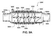
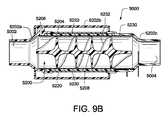
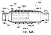
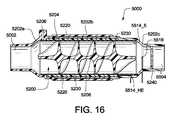
本技術の1つの態様は、呼吸治療装置によって患者の気道に送出される空気流の絶対湿度を増す加湿器に関する。前記加湿器は、下記を保持するように構成される。第1の水量保持するように構成されたリザーバ、圧力装置から空気流を受け取るように構成された空気入口から成る加湿器チャンバー、空気流を加湿器のチャンバーから患者のインタフェースに湿度を上げて送出するように構成された空気出口、加湿器のチャンバーを通る空気流の流路、第2の水量保持するように構成された加湿器ウイック(wick)、流路の軸方向への空気流の流路の少なくとも一部を実質的に囲むような形状を持った加湿器ウイックおよび加湿器のチャンバーを通って空気流の流路を長くするように構成された空気流バッフル、水の流れをリザーバから加湿器のウイックに送出するように構成された吐出メカニズム。ここで加熱エレメントは加湿器のウイックを加熱して第2の水量を蒸発させ、空気流の絶対湿度を上げるように構成され、加湿器のウイックは加湿器のチャンバーから取り外しできるようになっている。 One aspect of the present technology relates to a humidifier that increases the absolute humidity of an airflow delivered to a patient's airway by a respiratory therapy device. The humidifier is configured to hold: A humidifier chamber comprising a reservoir configured to hold a first volume of water, an air inlet configured to receive an air flow from the pressure device, and an increased flow of air from the humidifier chamber to the patient interface. An air outlet configured to provide an air flow through the humidifier chamber; a humidifier wick configured to hold a second amount of water; and a flow of air flow in an axial direction of the flow path. A humidifier wick shaped to substantially surround at least a portion of the path and an air flow baffle configured to lengthen the flow path of the air flow through the humidifier chamber, the flow of water from the reservoir; Discharge mechanism configured to deliver to the humidifier wick. Here, the heating element is configured to heat the humidifier wick to evaporate the second volume of water and increase the absolute humidity of the airflow, such that the humidifier wick is removable from the humidifier chamber. .
本技術のもう1つの態様によれば、加湿器のウイックは異方性を持つように構成できる。 According to another aspect of the present technology, the humidifier wick can be configured to be anisotropic.
本技術のもう1つの態様によれば、ウイッキング(wicking)の速さ(率)が第2の方向よりも第1の方向において大きくなるようにさらに構成してよい。 According to another aspect of the present technology, the wicking speed (rate) may be further configured to be greater in the first direction than in the second direction.
本技術のもう1つの態様によれば、第2の方向は空気流の方向であってよい。 According to another aspect of the present technology, the second direction may be a direction of an airflow.
本技術のもう1つの態様によれば、加湿器のウイックで囲まれた流路は実質的に円筒形であってよい。 According to another aspect of the present technology, the wicked channel of the humidifier may be substantially cylindrical.
本技術のもう1つの態様によれば、加湿器のウイックは1つまたはそれ以上の波型、くぼみ型、穿孔型、多孔型、織った、編んだ、織り目加工された、または焼結された表面から成るものでよい。 According to another aspect of the present technology, the humidifier wick is one or more corrugated, hollow, perforated, porous, woven, knitted, textured, or sintered. It may consist of a surface.
本技術のもう1つの態様によれば、加湿器のウイックは1つまたはそれ以上の紙、親水性繊維およびセルロース繊維で構成されてよい。 According to another aspect of the present technology, the humidifier wick may be composed of one or more papers, hydrophilic fibers and cellulosic fibers.
本技術のもう1つの態様によれば、加湿器のウイックは加熱エレメントのための基質で構成されてよい。 According to another aspect of the present technology, the humidifier wick may be comprised of a substrate for the heating element.
本技術のもう1つの態様によれば、加湿器のウイックは2〜30 gの水を保持するように構成されてよい。 According to another aspect of the present technology, the humidifier wick may be configured to hold 2-30 g of water.
本技術のもう1つの態様によれば、加湿器のウイックは加熱領域と非加熱領域から成ってよい。 According to another aspect of the present technology, the humidifier wick may consist of a heated area and a non-heated area.
本技術のもう1つの態様によれば、非加熱領域は加熱領域の上流に位置する上流非加熱領域から成っててよい。 According to another aspect of the present technology, the unheated region may comprise an upstream unheated region located upstream of the heated region.
本技術のもう1つの態様によれば、上流非加熱領域は加熱領域より早いウイッキング(wicking)速度としてよい。 According to another aspect of the present technology, the upstream unheated area may have a faster wicking rate than the heated area.
本技術のもう1つの態様によれば、上流非加熱領域の長さは加熱領域の約5%〜約20%としてよい。 According to another aspect of the present technology, the length of the upstream unheated area may be from about 5% to about 20% of the heated area.
本技術のもう1つの態様によれば、非加熱領域は加熱領域の下流に位置する下流非加熱領域から成ってよい。 According to another aspect of the present technology, the unheated area may comprise a downstream unheated area located downstream of the heated area.
本技術のもう1つの態様によれば、下流の非加熱領域の長さは加熱領域の約20%〜約40%としてよい。 According to another aspect of the present technology, the length of the downstream unheated area may be from about 20% to about 40% of the heated area.
本技術のもう1つの態様によれば、加湿器のウイックはフレームに連結されてよい。 According to another aspect of the present technology, the humidifier wick may be connected to a frame.
本技術のもう1つの態様によれば、前記フレームは加湿器のチャンバーに取り外し可能で連結されるように構成されてよい。 According to another aspect of the present technology, the frame may be configured to be removably coupled to a humidifier chamber.
本技術のもう1つの態様によれば、前記フレームは加湿器の外側から取り外すように構成されてよい。 According to another aspect of the present technology, the frame may be configured to be removed from outside a humidifier.
本技術のもう1つの態様によれば、前記フレームはグリップ面で構成されてよい。 According to another aspect of the present technology, the frame may be configured with a grip surface.
本技術のもう1つの態様によれば、前記フレームは加湿器ウイックと加熱エレメント間の熱的接触を促進するように構成されてよい。 According to another aspect of the present technology, the frame may be configured to facilitate thermal contact between the humidifier wick and the heating element.
本技術のもう1つの態様によれば、前記フレームはさらに空気流バッフルから成ってよい。 According to another aspect of the present technology, the frame may further comprise an airflow baffle.
本技術のもう1つの態様によれば、延長された経路はらせん形であってよい。 According to another aspect of the present technology, the extended path may be helical.
本技術のもう1つの態様によれば、加熱エレメントは抵抗性のある電気トラックから成ってよい。 According to another aspect of the present technology, the heating element may comprise a resistive electric track.
本技術のもう1つの態様によれば、前記抵抗性のある電気トラックは回路基板上に配置してよい。 According to another aspect of the present technology, the resistive electrical track may be disposed on a circuit board.
本技術のもう1つの態様によれば、前記回路基板は可撓性の回路基板であってよい。 According to another aspect of the present technology, the circuit board may be a flexible circuit board.
本技術のもう1つの態様によれば、前記抵抗性のある電気トラックは1つまたはそれ以上の抵抗素子のより糸から成ってよい。 According to another aspect of the present technology, the resistive electrical track may consist of a strand of one or more resistive elements.
本技術のもう1つの態様によれば、1つまたはそれ以上の抵抗素子のより糸は、加湿器チャンバーの表面の周りに複数のループを形成することができる。 According to another aspect of the present technology, the strands of one or more resistive elements can form a plurality of loops around the surface of the humidifier chamber.
本技術のもう1つの態様によれば、加熱エレメントは複数のループを固定するための接着剤をさらに含んでよい。 According to another aspect of the present technology, the heating element may further include an adhesive for securing the plurality of loops.
本技術のもう1つの態様によれば、吐出メカニズムは複数の流体接続を経て水の流れを加湿器のウイックに吐出するように構成されてよい。 According to another aspect of the present technology, the discharge mechanism may be configured to discharge a stream of water to the humidifier wick via a plurality of fluid connections.
本技術のもう1つの態様によれば、吐出メカニズムは事前吐出チャンバーを経て加湿器のウイックに流体的に接続してよい。 According to another aspect of the present technology, the discharge mechanism may be fluidly connected to the humidifier wick via a pre-discharge chamber.
本技術のもう1つの態様によれば、少なくとも1つの流体接続はバルブであってよい。 According to another aspect of the present technology, the at least one fluid connection may be a valve.
本技術のもう1つの態様によれば、吐出メカニズムはポンプを含めてよい。 According to another aspect of the present technology, the dispensing mechanism may include a pump.
本技術のもう1つの態様によれば、加湿器はさらに加湿器のウイックにおける1つまたはそれ以上の温度を測定するように構成された1つまたはそれ以上の温度センサーを含めてよい。 According to another aspect of the present technology, the humidifier may further include one or more temperature sensors configured to measure one or more temperatures at the humidifier wick.
本技術のもう1つの態様によれば、複数の温度センサーを空気流の方向に沿って配置してよい。 According to another aspect of the present technology, a plurality of temperature sensors may be arranged along the direction of the airflow.
本技術のもう1つの態様には、加湿器ウイックの飽和状態を示すように構成されたセンサーを含めてよい。 Another aspect of the present technology may include a sensor configured to indicate saturation of the humidifier wick.
本技術のもう1つの態様によれば、飽和状態を示すために、温度センサーを水供給入り口から最も離れた加湿器のウイックの周辺に配置してよい。 According to another aspect of the present technology, a temperature sensor may be placed around the humidifier wick furthest from the water supply inlet to indicate saturation.
本技術のもう1つの態様には、飽和状態が指示されると吐出メカニズムによって吐出を停止するかまたは遅くするように構成されたコントローラをさらに含めてよい。 Another aspect of the present technology may further include a controller configured to stop or delay ejection by an ejection mechanism when a saturation condition is indicated.
本発明の1つの態様は、呼吸治療装置によって患者の気道に送出する空気流の絶対湿度を上げる加湿器のための加湿器チャンバーに関する。加湿器チャンバーは圧力装置からの空気流を受けるように構成された空気入口、空気流を加湿器のチャンバーから湿度を上げて患者インタフェースに送出するように構成された空気出口、空気流のための加湿器を通った流路、水量を保持するように構成された加湿器ウイックおよび流路の軸方向への空気流のための流路の少なくとも一部を実質的に囲むための輪郭を有する加湿器ウイックを含めることができる。 One aspect of the present invention relates to a humidifier chamber for a humidifier that increases the absolute humidity of an airflow delivered to a patient's airway by a respiratory treatment device. The humidifier chamber has an air inlet configured to receive airflow from the pressure device, an air outlet configured to increase the humidity of the airflow from the humidifier chamber and deliver it to the patient interface, and for the airflow. Humidifier having a flow path through the humidifier, a humidifier wick configured to hold a quantity of water, and a contour to substantially surround at least a portion of the flow path for airflow in the axial direction of the flow path Vessel wicks can be included.
本技術のもう1つの態様によれば、加湿器ウイックは異方性を持つように構成できる。 According to another aspect of the present technology, the humidifier wick can be configured to be anisotropic.
本技術のもう1つの態様によれば、ウイッキングの速度が第2の方向より第1の方向において大きくなるように加湿器のウイックをさらに構成できる。 According to another aspect of the present technology, the humidifier wick can be further configured such that the wicking speed is greater in the first direction than in the second direction.
本技術のもう1つの態様によれば、第2の方向は空気流の方向であってよい。 According to another aspect of the present technology, the second direction may be a direction of an airflow.
本技術のもう1つの態様によれば、加湿器ウイックで囲まれた流路は実質的に円筒形であってよい。 According to another aspect of the present technology, the flow path surrounded by the humidifier wick may be substantially cylindrical.
本技術のもう1つの態様によれば、加湿器のウイックは1つまたはそれ以上の波型、くぼみ型、穿孔型、多孔型、織った、編んだ、織り目加工された、または焼結された表面から成るものでよい。 According to another aspect of the present technology, the humidifier wick is one or more corrugated, hollow, perforated, porous, woven, knitted, textured, or sintered. It may consist of a surface.
本技術のもう1つの態様によれば、加湿器のウイックは1つまたはそれ以上の紙、親水性繊維およびセルロース繊維で構成されてよい。 According to another aspect of the present technology, the humidifier wick may be composed of one or more papers, hydrophilic fibers and cellulosic fibers.
本技術のもう1つの態様によれば、加湿器のチャンバーは加熱エレメントで構成されてよい。 According to another aspect of the present technology, the humidifier chamber may be configured with a heating element.
本技術のもう1つの態様によれば、加湿器のウイックは加熱エレメントのための基質で構成されてよい。 According to another aspect of the present technology, the humidifier wick may be comprised of a substrate for the heating element.
本技術のもう1つの態様によれば、加湿器のウイックは2〜30 gの水を保持するように構成されてよい。 According to another aspect of the present technology, the humidifier wick may be configured to hold 2-30 g of water.
本技術のもう1つの態様によれば、加湿器のウイックは加熱領域と非加熱領域から成ってよい。 According to another aspect of the present technology, the humidifier wick may consist of a heated area and a non-heated area.
本技術のもう1つの態様によれば、非加熱領域は加熱領域の上流に位置する上流非加熱領域から成ってよい。 According to another aspect of the present technology, the unheated region may comprise an upstream unheated region located upstream of the heated region.
本技術のもう1つの態様によれば、上流非加熱領域は加熱領域より早いウイッキング(wicking)速度としてよい。 According to another aspect of the present technology, the upstream unheated area may have a faster wicking rate than the heated area.
本技術のもう1つの態様によれば、上流非加熱領域の長さは加熱領域の約5%〜約20%としてよい。 According to another aspect of the present technology, the length of the upstream unheated area may be from about 5% to about 20% of the heated area.
本技術のもう1つの態様によれば、非加熱領域は加熱領域の下流に位置する下流非加熱領域から成ってよい。 According to another aspect of the present technology, the unheated area may comprise a downstream unheated area located downstream of the heated area.
本技術のもう1つの態様によれば、下流の非加熱領域の長さは加熱領域の約20%〜約40%としてよい。 According to another aspect of the present technology, the length of the downstream unheated area may be from about 20% to about 40% of the heated area.
本技術のもう1つの態様によれば、加湿器のウイックはフレームに連結されてよい。 According to another aspect of the present technology, the humidifier wick may be connected to a frame.
本技術のもう1つの態様によれば、前記フレームは加湿器のチャンバーに取り外し可能で連結されるように構成されてよい。 According to another aspect of the present technology, the frame may be configured to be removably coupled to a humidifier chamber.
本技術のもう1つの態様によれば、前記フレームは加湿器の外側から取り外すように構成されてよい。 According to another aspect of the present technology, the frame may be configured to be removed from outside a humidifier.
本技術のもう1つの態様によれば、前記フレームはグリップ面で構成されてよい。 According to another aspect of the present technology, the frame may be configured with a grip surface.
本技術のもう1つの態様によれば、前記フレームは加湿器ウイックと加熱エレメント間の熱的接触を促進するように構成されてよい。 According to another aspect of the present technology, the frame may be configured to facilitate thermal contact between the humidifier wick and the heating element.
本技術のもう1つの態様によれば、前記フレームは流路を伸ばすためにさらに空気流バッフルから成ってよい。 According to another aspect of the present technology, the frame may further comprise an airflow baffle to extend the flow path.
本技術のもう1つの態様によれば、延長された経路はらせん形であってよい。 According to another aspect of the present technology, the extended path may be helical.
本技術のもう1つの態様によれば、加熱エレメントは抵抗性のある電気トラックから成ってよい。 According to another aspect of the present technology, the heating element may comprise a resistive electric track.
本技術のもう1つの態様によれば、前記抵抗性のある電気トラックは回路基板上に配置してよい。 According to another aspect of the present technology, the resistive electrical track may be disposed on a circuit board.
本技術のもう1つの態様によれば、前記回路基板は可撓性の回路基板であってよい。 According to another aspect of the present technology, the circuit board may be a flexible circuit board.
本技術のもう1つの態様によれば、前記抵抗性のある電気トラックは1つまたはそれ以上の抵抗素子のより糸から成ってよい。 According to another aspect of the present technology, the resistive electrical track may consist of a strand of one or more resistive elements.
本技術のもう1つの態様によれば、1つまたはそれ以上の抵抗素子のより糸は、加湿器チャンバーの表面の周りに複数のループを形成することができる。 According to another aspect of the present technology, the strands of one or more resistive elements can form a plurality of loops around the surface of the humidifier chamber.
本技術のもう1つの態様によれば、加熱エレメントは複数のループを固定するための接着剤をさらに含んでよい。 According to another aspect of the present technology, the heating element may further include an adhesive for securing the plurality of loops.
本技術のもう1つの態様は、加湿器のウイックにおける1つまたはそれ以上の温度を測定するように構成された1つまたはそれ以上の温度センサーを含めてよい。 Another aspect of the present technology may include one or more temperature sensors configured to measure one or more temperatures in the humidifier wick.
本技術のもう1つの態様によれば、複数の温度センサーを空気流の方向に沿って配置してよい。 According to another aspect of the present technology, a plurality of temperature sensors may be arranged along the direction of the airflow.
本技術のもう1つの態様には、加湿器ウイックの飽和状態を示すように構成されたセンサーを含めてよい。 Another aspect of the present technology may include a sensor configured to indicate saturation of the humidifier wick.
本技術のもう1つの態様によれば、飽和状態を示すために、温度センサーを水供給入り口から最も離れた加湿器のウイックの周辺に配置してよい。 According to another aspect of the present technology, a temperature sensor may be placed around the humidifier wick furthest from the water supply inlet to indicate saturation.
本技術の1つの態様は加湿器の、例えば医療加湿器、加湿器のウイックの安定性を決定する方法に関する。加湿器は加湿器ウイックおよび1つまたはそれ以上の信号を受信するようにおよび/または1つまたはそれ以上の信号を発生するように構成されたコントローラを含めることができ、加湿器のウイックは水量を保持するように構成できる。前記方法はコントローラで入力値のセットを決定することを含み、ここで入力値のセットは加湿器のウイックの状態を示し、入力値のセットは少なくとも1つのユーザ入力、少なくとも1つのセンサーおよび記憶装置によってコントローラに提供され、入力値のセットと基準値のセットに基づき、コントローラで加湿器の条件を決定し、決定された条件に基づきコントローラで信号を生成し、加湿器のウイックを加湿器で使用することの適合性を示す。 One aspect of the present technology relates to a method of determining the stability of a humidifier, for example, a medical humidifier, a humidifier wick. The humidifier may include a humidifier wick and a controller configured to receive one or more signals and / or to generate one or more signals, wherein the humidifier wick has a water volume. Can be held. The method includes determining a set of input values at a controller, wherein the set of input values indicates a state of a humidifier wick, and the set of input values is at least one user input, at least one sensor, and a storage device. Is provided to the controller, based on the set of input values and the set of reference values, the controller determines the condition of the humidifier, generates a signal in the controller based on the determined condition, and uses the humidifier wick with the humidifier Demonstrate the suitability of
本技術のもう1つの態様によれば、入力値のセットは、ウイック型のデータ、ウイックの使用データおおよび測定したウイック条件データの1つまたはそれ以上を含むことができる。 According to another aspect of the present technology, the set of input values can include one or more of wick-type data, wick usage data, and measured wick condition data.
本技術のもう1つの態様によれば、入力値のセットがウイック型のデータを含む場合は、ウイック型のデータは、ウイックモデル、製造日、ウイックの材料、ウイックの構造、ウイックの寸法および最初の水容量を含むことができる。 According to another aspect of the present technology, if the set of input values includes wick-type data, the wick-type data includes the wick model, date of manufacture, wick material, wick structure, wick dimensions, and wick size. Water capacity.
本技術のもう1つの態様によれば、入力値のセットがウイックの使用データから成り、ウイックの使用データは以下の1つまたはそれ以上を含むことができる:最後の取り換え日、使用時間、加湿器のウイックを使用して蒸発した水量、および加湿器のウイックの洗浄回数。 According to another aspect of the present technology, the set of input values comprises wick usage data, and the wick usage data may include one or more of the following: last replacement date, usage time, humidification. The amount of water evaporated using the wick of the humidifier, and the number of cleanings of the humidifier wick.
本技術のもう1つの態様によれば、入力値のセットが測定したウイック条件データを含む場合は、測定したウイック条件データは測定温度、水容量および水含有量の1つまたはそれ以上を含むことができる。 According to another aspect of the present technology, if the set of input values includes measured wick condition data, the measured wick condition data includes one or more of measured temperature, water volume, and water content. Can be.
本技術のもう1つの態様によれば、条件セットは水容量、水含有量おおび残留有用寿命の1つまたはそれ以上を含むことができる。 According to another aspect of the present technology, the condition set can include one or more of water capacity, water content, and remaining useful life.
本技術のもう1つの態様によれば、基準値のセットは温度を含むことができる。 According to another aspect of the present technology, the set of reference values may include a temperature.
本技術のもう1つの態様によれば、基準値のセットは温度勾配を含むことができる。 According to another aspect of the present technology, the set of reference values may include a temperature gradient.
本技術のもう1つの態様によれば、基準値のセットは参照テーブルを含むことができる。 According to another aspect of the present technology, the set of reference values may include a look-up table.
本技術のもう1つの態様によれば、前記方法はコントローラで生成された信号に対応して、視覚および/または可聴通信装置を使用して、加湿器のウイックの適合性についてユーザと交信することをさらに含むことができる。 According to another aspect of the present technology, the method includes communicating with a user about the suitability of the humidifier wick using a visual and / or audible communication device in response to the signal generated by the controller. May be further included.
本技術のもう1つの態様は、加湿器、例えば医療加湿器、の加湿器ウイックの水含有量を決定する方法に関する。加湿器は加湿器ウイックと、1つまたはそれ以上の信号を受信しおよび/または1つまたはそれ以上の信号を発生するように構成されたコントローラを含むことができ、加湿器ウイックは水量を保持するように構成できる。この方法は、加湿器のウイックの第1の領域と熱的接触のある第1の温度センサーと、加湿器のウイックの第2の領域と熱的接触のある第2の温度センサーを提供すること、熱入力を加湿器のウイックに適用すること、例えば加熱エレメントで、第1の温度センサーと第2の温度センサーで測定した温度セットを測定すること、第1の温度センサーと第2の温度センサー、例えばコントローラ、における予測した温度セットを決定すること、第1の温度センサーと第2の温度センサーから受信した測定温度セットの比較と、予測した温度セットに基づき加湿器ウイックの水含有量を決定することを含むことができる。 Another aspect of the present technology relates to a method for determining the water content of a humidifier wick of a humidifier, for example, a medical humidifier. The humidifier may include a humidifier wick and a controller configured to receive one or more signals and / or generate one or more signals, wherein the humidifier wick holds a volume of water. Can be configured. The method provides a first temperature sensor in thermal contact with a first region of the humidifier wick and a second temperature sensor in thermal contact with a second region of the humidifier wick. Applying the heat input to the humidifier wick, e.g. measuring the temperature set with the first temperature sensor and the second temperature sensor with the heating element, the first temperature sensor and the second temperature sensor Determining the predicted temperature set in the controller, for example, comparing the measured temperature sets received from the first temperature sensor and the second temperature sensor, and determining the water content of the humidifier wick based on the predicted temperature set Can include:
本技術のもう1つの態様によれば、予測された温度セットは加湿器のウイックへの水流量と熱入力の割合の1つまたはそれ以上に基づき決定できる。 According to another aspect of the present technology, the predicted temperature set can be determined based on one or more of a water flow rate and a heat input rate to the humidifier wick.
本技術のもう1つの態様によれば、第1の温度センサーは加湿器のウイックにまたはその周辺近くに配置することができる。 According to another aspect of the present technology, the first temperature sensor can be located at or near the humidifier wick.
本技術のもう1つの態様によれば、第1の温度は加湿器のウイックの水入り口から最も離れた加湿器のウイックの周辺に配置してよい。 According to another aspect of the present technology, the first temperature may be located around the humidifier wick furthest from the humidifier wick water inlet.
本技術のもう1つの態様によれば、測定温度セットの温度が予測温度セットの対応する温度の閾値範囲の外にあるかどうかを比較により決定できる。 According to another aspect of the present technology, a comparison can determine whether the temperature of the measured temperature set is outside a corresponding temperature threshold range of the predicted temperature set.
本技術の1つの態様は、加湿器から、例えば医療加湿器、送出された空気流の流路における凝結の発生を検出する方法に関する。この方法は流路にある第1のセンサーで空気流の第1の特性の第1の測定を決定すること、流路にある第2のセンサーで空気流の第1の特性の基準値を決定すること、第1の測定値と基準値を、第1のセンサーと第2のセンサーと通信しているコントローラで比較すること、コントローラでの比較に基づいて流路で凝結が発生したか決定すること、流路で凝結が発生したかどうかを示す信号をコントローラで生成することから成る。 One aspect of the present technology relates to a method of detecting the occurrence of condensation from a humidifier, for example, a medical humidifier, a flow path of a delivered airflow. The method includes determining a first measurement of a first property of the air flow with a first sensor in the flow path, and determining a reference value of the first property of the air flow with a second sensor in the flow path. Comparing the first measured value and the reference value with a controller in communication with the first sensor and the second sensor, and determining whether condensation has occurred in the flow path based on the comparison at the controller. The controller generates a signal indicating whether condensation has occurred in the flow path.
本技術のもう1つの態様によれば、第1の特性における低下があった場合、第1の測定に対する基準値から凝結の発生をコントローラで決定することができる。 According to another aspect of the present technology, if there is a decrease in the first characteristic, the occurrence of condensation can be determined by the controller from a reference value for the first measurement.
本技術のもう1つの態様によれば、第1の測定に対する基準値から第1の特性の低下は所定の閾値以上であってよい。 According to another aspect of the present technology, a decrease in the first characteristic from the reference value for the first measurement may be equal to or greater than a predetermined threshold.
本技術のもう1つの態様によれば、基準値は第1の特性の第2の測定であってよい。 According to another aspect of the present technology, the reference value may be a second measurement of the first property.
本技術のもう1つの態様によれば、第2の測定は第1の測定の上流で決定してよい。 According to another aspect of the present technology, the second measurement may be determined upstream of the first measurement.
本技術のもう1つの態様によれば、基準値は空気流の第1の特性の予測であってよい。 According to another aspect of the present technology, the reference value may be a prediction of a first characteristic of the airflow.
本技術のもう1つの態様によれば、予測は定常状態の条件に基づいて決定してよい。 According to another aspect of the present technology, the prediction may be determined based on steady state conditions.
本技術のもう1つの態様によれば、予測は下記の1つまたはそれ以上に基づいて決定してよい:空気流の圧力、空気流の流量、周囲温度、周囲湿度、周囲圧力、空気流への熱伝導率、空気流と周囲との間の熱伝導率。 According to another aspect of the present technology, the prediction may be determined based on one or more of the following: air flow pressure, air flow rate, ambient temperature, ambient humidity, ambient pressure, air flow to Thermal conductivity, the thermal conductivity between the airflow and the surroundings.
本技術のもう1つの態様によれば、空気流の第1の特性は湿度、温度、または温度の変化率である。 According to another aspect of the present technology, the first characteristic of the airflow is humidity, temperature, or a rate of change of temperature.
本技術のもう1つの態様によれば、予測は定常状態に基づいて決定してよい。 According to another aspect of the present technology, the prediction may be determined based on a steady state.
本技術の1つの態様は、加湿器の加湿器ウイックに蓄積した外雑物の位置および/または蓄積率を制御する方法を対象とするものである。加湿器は、加湿器ウイック、加湿器ウイックに熱を加える加熱エレメント、加湿器ウイックに水を供給する水供給メカニズムおよび1つまたはそれ以上の信号を受信するおよび/または1つまたはそれ以上の信号を生成するように構成されたコントローラ、水量を保持するように構成された加湿器クイックから成ってよい。この方法は、コントローラで下記の少なくとも1つを変化させて加湿器の加湿器ウイック上の水の境界の位置および/またはパターンを制御することから成ってよい:加熱エレメントから加湿器ウイックへの熱出力、水供給メカニズムから加湿器ウイックへの水の流量;および加熱エレメントからの熱出力および/または水供給からの水量を調整することによる加湿器ウイック内の水分布のパターン。ここに水の境界の場所および/またはパターンを制御すると、水の境界の位置および/またはパターンに基づき、加湿器ウイックの所定の領域における外雑物の蓄積を生じる。 One aspect of the present technology is directed to a method for controlling the location and / or rate of accumulation of contaminants accumulated in a humidifier wick of a humidifier. The humidifier comprises a humidifier wick, a heating element for applying heat to the humidifier wick, a water supply mechanism for supplying water to the humidifier wick, and receiving one or more signals and / or one or more signals And a humidifier quick configured to hold the amount of water. The method may comprise controlling the location and / or pattern of water boundaries on the humidifier wick of the humidifier by changing at least one of the following with a controller: heat from the heating element to the humidifier wick The pattern of water distribution in the humidifier wick by adjusting the power, the flow rate of water from the water supply mechanism to the humidifier wick; and the heat output from the heating element and / or the amount of water from the water supply. Controlling the location and / or pattern of the water boundary here results in the accumulation of contaminants in certain areas of the humidifier wick based on the location and / or pattern of the water boundary.
本技術のもう1つの態様によれば、この方法はセンサーで水の中の外雑物の含有量を検出すること、センサーで検出した外雑物の含有量に基づきコントローラで水質を決定することをさらに含めることができる。 According to another aspect of the present technology, the method includes detecting foreign matter content in water with a sensor, and determining water quality with a controller based on the foreign matter content detected by the sensor. Can be further included.
本技術のもう1つの態様によれば、センサーで水の中の外雑物の含有量を決定することは、水の伝導率を測定することをさらに含めることができる。 According to another aspect of the present technology, determining the content of contaminants in the water with the sensor can further include measuring the conductivity of the water.
本技術のもう1つの態様によれば、センサーで水の中の外雑物の含有量を検出することは、水の抵抗率を水と接触した電極で測定することをさらに含めることができる。 According to another aspect of the present technology, detecting the content of foreign matter in the water with the sensor can further include measuring the resistivity of the water with an electrode in contact with the water.
本技術のもう1つの態様によれば、電極は加湿器ウイックと加湿器ウイックに入った水中に配置でき、電極で測定した抵抗率は、加湿器ウイックに蓄積した外雑物のレベルに直接相関することができる。 According to another aspect of the present technology, the electrodes can be placed in the humidifier wick and the water contained in the humidifier wick, and the resistivity measured at the electrodes is directly correlated to the level of contaminants accumulated in the humidifier wick. can do.
本技術のもう1つの態様によれば、水供給メカニズムからの水の流量が変化すると、水の流量を最少水量と最大水量の間で変化させることができる。 According to another aspect of the present technology, when the flow rate of the water from the water supply mechanism changes, the flow rate of the water can be changed between a minimum flow rate and a maximum flow rate.
本技術のもう1つの態様によれば、水の流量はリニアにまたは正弦関数的に変化させることができる。 According to another aspect of the present technology, the flow rate of water can be varied linearly or sinusoidally.
本技術のもう1つの態様によれば、水の境界の位置を制御すると、水の境界の位置は少なくとも第1の位置と第2の位置の間で移動するように往復運動で変化させることができる。 According to another aspect of the present technology, controlling the position of the water boundary may cause the position of the water boundary to reciprocate to move at least between the first position and the second position. it can.
本技術のもう1つの態様によれば、加熱エレメントから加湿器ウイックへの熱出力が変化すると、熱出力は最少熱出力と最大熱出力の間で変化させることができる。 According to another aspect of the present technology, as the heat output from the heating element to the humidifier wick changes, the heat output can be varied between a minimum heat output and a maximum heat output.
本技術の別の態様によれば、熱出力をリニアにまたは正弦関数的に変化させることができる。
According to another aspect of the present technology,Ru can be heat output linearly or sinusoidallychanges.
もちろん態様の部分は本技術の準態様を形成することができる。また、いろいろな準態様および/または態様は、いろいろな様式で組み合わせることができ本技術の追加の態様または準態様を構成することができる。 Of course, aspects may form sub-aspects of the present technology. Also, various sub-aspects and / or aspects may be combined in various manners to form additional aspects or sub-aspects of the present technology.
技術のそのほかの特徴は、以下の詳細な説明、要約、図面および請求項に含まれる情報を考慮すれば明らかであろう。 Other features of the technology will be apparent in view of the following detailed description, abstract, drawings and information contained in the claims.
本技術は制限ではなく、実施例によって説明され、添付の図面における数字において同じ参照番号は同じエレメントを参照する。
4.1 治療システム
4.1 Treatment system
本技術をさらに詳細に説明する前に、本技術は本明細書に記載された変わることのある特定の実施例に限定されないことを理解されたい。またこの開示で使用されている専門用語は、本明細書中で議論される特定の実施例のみを記述するのが目的であり、限定する意図のないことを理解すべきである。 Before describing the present technology in further detail, it is to be understood that this technology is not limited to the particular embodiments described, which may vary. It should also be understood that the terminology used in this disclosure is for purposes of describing only the particular embodiments discussed herein, and is not intended to be limiting.
以下の記述は1つまたはそれ以上の共通の特性および/または特徴を共有するいろいろな実施例に関連して提供される。任意の1実施例の1つまたはそれ以上の特徴は、別の実施例または他の実施例の1つまたはそれ以上の特徴と組み合わせ可能であることを理解されたい。さらに任意の実施例における任意の単一の特徴または特徴の組み合わせが、さらなる実施例を構成できる。
5.1 治療システムThe following description is provided in connection with various embodiments that share one or more common characteristics and / or features. It is to be understood that one or more features of any one embodiment can be combined with one or more features of another embodiment or other embodiments. Furthermore, any single feature or combination of features in any embodiment may constitute a further embodiment.
5.1 Treatment system
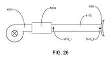
1つの形態において、本技術は呼吸器疾患を治療するシステムから成る。例えば、システムはRPT装置4000、加湿器5000、空気回路4170および患者インタフェース3000から成ってよい。
5.2 治療In one aspect, the present technology comprises a system for treating a respiratory disease. For example, the system may consist of
5.2 Treatment
1形態において、本技術は陽圧を患者1000の気道入り口に適用するステップから成る呼吸障害の治療の方法から成る。
5.2.1 OSAのための鼻CRAPIn one form, the technology comprises a method of treating a disordered breathing comprising applying a positive pressure to an airway entrance of a
5.2.1 Nasal CRAP for OSA
1形態において、本技術は患者に鼻連続陽圧気道圧を適用して患者における閉塞性睡眠時無呼吸を治療する方法から成る。 In one form, the technology comprises a method of applying continuous nasal positive airway pressure to a patient to treat obstructive sleep apnea in the patient.
本技術のある実施例において、陽圧の空気が患者の1つまたは両方の鼻孔を通して鼻腔に供給される。
5.3 患者インタフェース3000In certain embodiments of the present technology, positive pressure air is supplied to the nasal cavity through one or both nostrils of the patient.
5.3
本技術の1態様による非侵襲患者インタフェース3000は、(例えば図3に示すような)下記の機能面を有している:シール形成構造3100、プレナムチャンバー3200、位置決めおよび安定化構造3300および空気回路4170へ接続するための接続口3600。患者インタフェース3000はさらに図3に示すようなある形態の額支持3700を含むことができる。場合によっては、機能面は1つまたはそれ以上の物理的コンポーネントによって提供されてよい。ある形態では、1つの物理的コンポーネントが1つまたはそれ以上の機能的態様を提供することができる。使用中は、気道への空気の供給が陽圧になるようにシール形成構造3100は患者の気道入り口を囲むように配置される。 The
1つの形態において、患者インタフェース3000は、吐き出した二酸化炭素をウォッシュアウトできるように構築されかつ配置されたベント3400を含む。 In one form, the
本技術によるベント3400の1形態は、例えば約20から約80または約40から約60または約45から約55の穴を有している。 One form of
ベント3400はプレナムチャンバー3200に位置してよい。代案として、ベント3400は例えば、自在軸受のような分離構造の中に位置してよい。
5.4 RPT装置4000
5.4
本技術の1態様によるRPT装置4000は、機械的および空気的コンポーネント4100、電気的コンポーネント4200から成り、1つまたはそれ以上のアルゴリズムを実行するようにプログラムされている。(例えば、図4Aに示す)RPT装置は、2つの部分に形成された、上部4012と下部4014,外部ハウジング4010を有する。さらに外部ハウジング4010は1つまたはそれ以上のパネル(複数)4015を含むことができる。RPT装置4000は、RPT装置4000の1つまたはそれ以上の内部コンポーネントを支持するシャーシ4016を含んでよい。1つの形態において、空気ブロック4020はシャーシ4016で支持されるかまたはその一部として形成される。RPT装置はハンドル4018を含んでよい。 An
(例えば図4Bに示す)RPT装置4000の空気路は、入口フィルター4112、入り口マフラー4122、陽圧で空気を供給できる圧力装置4140(例えば送風機4142)および出口マフラー4124を含んでよい。圧力センサー4272および流れセンサー4274のような1つまたはそれ以上の変換器4270を空気路に含めるかまたは連結してよい。 The air passage of the RPT device 4000 (eg, shown in FIG. 4B) may include an
空気ブロック4020は、RPT装置4000内にある空気路の一部とすることができる。
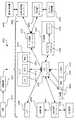
RPT装置4000は、電源4210のような電気コンポーネント4200、1つまたはそれ以上の入力装置4220、中央コントローラ4230、治療装置コントローラ4240、圧力装置4140、1つまたはそれ以上の保護回路4250、メモリー4260、(例えば、1つまたはそれ以上の流量センサー4274、圧力センサー4272および速度センサー4276のような)変換器4270、データ通信インタフェース4280および(例えば、ディスプレイ4294およびディスプレイ・ドライバー4292などの)1つまたはそれ以上の出力装置4290から成ることができる。電気コンポーネント4200は単一のプリント板ユニット(PCBA)4202上に置くことができる。代案として、RPT装置4000は1つ以上のPCBA 4202を含んでよい。 The
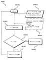
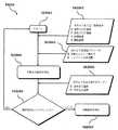
RPT装置4000の中央コントローラ4230は、事前処理モジュール、治療エンジンモジュール、圧力制御モジュールおよび故障条件モジュールのような1つまたはそれ以上のアルゴリズムモジュールを実行するようにプログラムできる。
5.4.1 RPT装置の機械的および空気的コンポーネンツ4100
5.4.1.1 空気フィルター(複数)4110The
5.4.1 Mechanical and Pneumatic Components of RPT Equipment 4100
5.4.1.1 Air filter (s) 4110
本技術の1形態によるRPT装置は、空気フィルター4110または複数の空気フィルター4110を含むことができる。 An RPT device according to one form of the present technology may include an
例えば、空気フィルター4110は入口空気フィルター4112として送風機4142の空気通路の上流の初めに、または出口空気フィルター4114としてRPT装置の出口に置いてよい。図4Bを参照。
5.4.1.2 マフラー(複数)4120For example, the
5.4.1.2 Muffler (s) 4120
本技術の1形態として、入り口マフラー4122は圧力装置4140の上流または圧力装置4140の下流のような空気通路に置かれる。
5.4.1.3 圧力装置4140In one form of the present technology, the inlet muffler 4122 is located in an air passage, such as upstream of the
5.4.1.3
本技術の1形態として、陽圧の空気流を生成する圧力装置4140は制御可能な送風機4142である。例えば送風機は、ボリュートの中に収めた一つまたはそれ以上のインペラーを有するブラシレスDCモータ4144を含む。送風機は例えば約120リットル/分の陽圧の空気を、約4cmH2Oから約20cmH2Oの範囲またはそのほかの形態で約30cmH2Oまでの範囲で吐出できる。送風機は、その開示をここに参考のため包含する下記の任意の1つ特許または特許出願に記載されている送風機であってよい:米国特許番号7,866,944;米国特許番号8,638,014;米国特許番号8,636,479;およびPCT特許公開番号WO 2013/020167。
5.4.1.4 漏れ防止弁4160In one form of the present technology, the
5.4.1.4
本技術の一形態において、加湿器5000と空気ブロック4020の間に漏れ防止弁が置かれる。この漏れ防止弁は、加湿器5000から上流に、例えばモータ4144へ、水が流れるリスクを低減するために構成されかつ配置される。
5.4.1.5 空気回路4170In one form of the present technology, a leak prevention valve is placed between the
5.4.1.5
本技術の態様に従った空気回路4170は、空気ブロック4020と患者インタフェース3000間に空気流ができるように構築されかつ配置される。いくつかの形態において空気回路4170は、空気回路4170を通って流れる空気流を加熱するように構成された加熱エレメントを含むことができる。加熱エレメントから成る空気回路4170の1例が米国特許8,733,349に開示されており、ここに参考のため包含する。 The
1つの形態において、空気回路4170は複数のゾーンから成ってよく、それぞれが互いに独立して制御される加熱エレメント4171から成る。
5.4.1.6 酸素補給4180In one form, the
5.4.1.6
本技術の1形態において、補充酸素4180が例えば空気ブロック4020の上流、空気回路4170へまたは患者インタフェース3000へなど、空気通路中の1つまたはそれ以上のポイントに補充される。
5.4.2 RPT装置電気コンポーネンツ4200
5.4.2.1 電源4210In one form of the present technology,
5.4.2 RPT
5.4.2.1
本技術の1形態として、電源4210はRPT装置4000の外部ハウジング4010の中にある。本技術のもう1つの形態において、電源4210はRPT装置4000の外部ハウジング4010の外にある。 In one form of the present technology,
本技術の1形態において、電源4210はRPT装置4000にのみ電力を供給する。本発明のもう1つの形態において、電源4210はRPT装置4000と加湿器5000の両方に電力を供給する。
5.4.2.2 入力装置4220In one form of the present technology,
5.4.2.2
本技術の1形態において、RPT装置4000は作業者が装置と交流できるように、ボタン、スイッチまたはダイアルの形態の1つまたはそれ以上の入力装置4220を含む。ボタン、スイッチまたはダイアルは物理的装置またはタッチスクリーンからアクセスできるソフトウエア装置であってよい。1つの形態において、ボタン、スイッチまたはダイアルはハウジング4010に物理的に接続するかまたはもう1つの形態では、中央コントローラ4230と電気的接続にあるレシーバーとの無線通信であってよい。 In one form of the present technology, the
1つの形態において、入力装置4220は作業者が値および/またはメニューオプションを選択できるように構築されかつ配置される。
5.4.2.3 中央コントローラ4230In one form,
5.4.2.3
本技術の1形態において、中央コントローラ4230は入力装置4220から入力信号(複数)を受信し、出力装置4290および/または治療装置コントローラ4240へ出力信号(複数)を提供するように構築された専用の電子回路である。 In one form of the present technology, the
1形態において、中央コントローラ4230はアプリケーション特有の集積回路である。中央コントローラ4230は離散的電子コンポーネンツを含んでよい。 In one form,
本技術のもう1つの形態において、中央コントローラ4230はx86 INTELプロセッサーのようなRPT装置4000を制御するのに適したプロセッサーである。 In another form of the present technology,
本技術のもう1つの形態によるRPT装置4000を制御するのに適したプロセッサーは、ARM HoldingsのARM Cortex-Mプロセッサーに基づいたプロセッサーを含む。例えば、ST MICROELECTRONICS のSTM232シリーズ・マイクロコントローラを使用できる。 Processors suitable for controlling the
本技術のさらなる代案の形態によるRPT装置4000を制御するのに適したもう1つのプロセッサーは、ARM9-に基づいた32-ビット RISC CPUから選択された要素を含む。例えば、ST MICROELECTRONICS のSTR9シリーズ・マイクロコントローラを使用してよい。 Another processor suitable for controlling the
本技術のある代案の形態において、16ビットRISC CPUをRPT装置4000のプロセッサーとして使用できる。例えば、TEXAS INSTRUMENTSが製造しているマイクロコントローラのMSP430ファミリーからのプロセッサーを使用できる。 In an alternative form of the present technology, a 16-bit RISC CPU can be used as the processor of the
中央コントローラ4230は、1つまたはそれ以上の変換器4270、1つまたはそれ以上の加湿器の変換器および1つまたはそれ以上の入力装置4220からの入力信号のような入力信号(複数)を受信するように構築できる。
中央コントローラ4230は、1つまたはそれ以上の出力装置4290、治療装置コントローラ4240、データ通信インタフェース4280および加湿器コントローラ5550に出力信号(複数)を提供するように構築できる。
本技術のいくつかの形態において、中央コントローラ4230または複数のこのような中央コントローラは、メモリー4260のような非一時的コンピュータ可読の記憶媒体に保存されたコンピュータプログラムとして表される1つまたはそれ以上のアルゴリズムのような本明細書に記載の1つまたはそれ以上のアルゴリズムを組み込むように構成されてよい。場合によっては、以前に議論したように、このようなプロセッサー(複数)はRPT装置4000に組み込んでよい。しかし本技術のいくつかの形態では、呼吸治療の吐出を直接制御することなく、本明細書に記載の任意の方法論を実施する目的で、RPT装置4000の圧力生成コンポーネントとは離散的に組み込むことができる。例えば、このようなプロセッサーは、本明細書に記載の任意のセンサーからの保存されたデータを解析して、RPT装置のための制御設定を決める目的で、本明細書に記載の任意の方法論を実施できる。
5.4.2.4 時計4232In some forms of the present technology, the
5.4.2.4
RPT装置4000は、中央コントローラ4230に接続された時計4232を含めることができる。この時計は、モニター、カウントまたは記録時間のすくなくとも1つに設定される。
5.4.2.5 治療装置コントロ―ラ4240
5.4.2.5
本技術の1形態において、治療装置コントローラ4240は、中央コントローラ4230が実行するアルゴリズムの一部をなす圧力制御モジュールである。 In one form of the present technology,
本技術の1形態において、治療装置コントローラ4240は専用のモータ制御の集積回路である。例えば、ONSEMIが製造しているMC33035ブラシレスDCモータコントローラの1形態である。
5.4.2.6 保護回路4250In one form of the present technology, the
5.4.2.6
本技術によるRPT装置4000は、1つまたはそれ以上の保護回路4250を含む。 The
本技術による保護回路4250の1つの形態は、電気的保護回路である。 One form of the
本技術による保護回路4250は、温度および/または圧力安全回路である。
5.4.2.7 メモリー4260The
5.4.2.7
本技術の1形態により、RPT装置4000はメモリー4260、例えば非揮発性メモリー4260、を含む。いくつかの形態において、メモリー4260はバッテリー駆動のスタティックRAMを含むことができる。いくつかの形態では、メモリー4260は揮発性RAMを含むことができる。 According to one form of the present technology,
メモリー4260はPCBA 4202上に置いてよい。メモリー4260は、EEPROMまたはNANDフラッシュの形態とすることができる。 The
追加でまたは代案として、RPT装置4000は、例えばSecure Digital (SD)標準で作ったメモリーカードのようなの取り外し形態のメモリー4260を含むことができる。 Additionally or alternatively, the
本技術の1つの形態において、メモリー4260は、1つまたはそれ以上のアルゴリズムのような、本明細書に記載の1つまたはそれ以上の方法論を表現するコンピュータプログラムのインストラクションが搭載された非一時的なコンピュータ可読記憶媒体として働く。
5.4.2.8 変換器4270In one form of the technology, the
5.4.2.8
変換器はRPT装置4000の内部でも外部でもよい。外部変換器は空気回路4170、加湿器5000および/または患者インタフェース3000の上に置いてもまたはその一部を形成するものであってよい。外部変換器4270は、データをRPT装置に送信または移送するドップラーレーダ動きセンサーのような非接触センサーの形態であってよい。 The converter may be internal or external to the
本技術の1つの形態において、1つまたはそれ以上の変換器4270を空気の特性を、例えば空気通路の中または周囲空気の1つまたはそれ以上のポイントにおいて、測定するように構築しかつ配置してよい。もう1つの形態において、1つまたはそれ以上の変換器4270を、モータ速度および/またはモータの電流のようなRPT装置4000の特性を測定するように構築してよい。
5.4.2.8.1 流れ4274In one form of the present technology, one or
5.4.2.8.1
本技術による流れ変換器4274は、例えばSENSIRIONのSDP600シリーズ差圧変換器のような、差圧変換器に基づいたものとすることができる。差圧変換器は流体回路と流体連結されており、圧力変換器のそれぞれの1つが流れ制限エレメント中の第1のポイントと第2のポイントに接続されている。 A
使用中は、流れ変換器4274からの合計流量Qtを示す信号を中央コントローラ4230が受信する。
5.4.2.8.2 圧力4272During use, it receives a signal indicating the total flow rate Qt from the
5.4.2.8.2
本技術による圧力変換器4272は、空気回路と流体接続となるよう配置される。適当な圧力変換器の例は、HONEYWELL ASDXシリーズのセンサーである。代案の適切な圧力変換器は、GHENERAL ELECTRICのNPAシリーズのセンサーである。 The
使用中は、圧力変換器4272からの信号を中央コントローラ4230が受信する。1つの形態において、圧力変換器4272からの信号を中央コントローラ4230が受信する前にフィルターを通すことができる。
5.4.2.8.3 モータ速度4276In use, the signal from the
5.4.2.8.3
本技術の1形態においてモータ速度信号が生成される。モータ速度信号は治療装置コントローラ4240によって提供できる。モータ速度信号は、例えばホール効果センサーのような速度センサーで生成できる。
5.4.2.9 データ通信インタフェース4280In one form of the present technology, a motor speed signal is generated. The motor speed signal can be provided by the
5.4.2.9
本技術の1形態において、データ通信インタフェース4280を提供でき、中央コントローラ4230に接続できる。データ通信インタフェース4280は遠隔外部通信ネットワーク4282に接続可能である。データ通信インタフェース4280はローカルの外部通信ネットワーク4284に接続可能である。好ましくは、遠隔外部通信ネットワーク4282は遠隔外部装置4286に接続可能である。好ましくは、ローカル外部通信ネットワーク4284はローカルの外部装置4288に接続可能である。 In one form of the present technology, a
1つの形態において、データ通信インタフェース4280は中央コントローラ4230の一部であってよい。もう1つの形態において、データ通信インタフェース4280は、中央コントローラ4230とは別の集積回路であってよい。 In one form,
1つの形態において、遠隔外部通信ネットワーク4282はインターネットであってよい。データ通信インタフェース4280は有線接続(例えば、イーサネット(登録商標)経由または光ファイバー)またはインターネットに接続する無線プロトコルであってよい。 In one form, the remote
1つの形態において、ローカル外部通信ネットワーク4284はBluetooth(登録商標)または消費者赤外プロトコルのような1つまたはそれ以上の通信標準を利用する。 In one form, local
1つの形態において、遠隔外部装置4286は1つ以上のコンピュータ、例えばネットワーク・コンピュータのクラスターであってよい。1つの形態において、遠隔外部装置4286は、物理的コンピュータと言うよりむしろ仮想コンピュータであってよい。いずれの場合でも、このような遠隔外部装置4286には臨床医のような適切に権限を与えられた人がアクセスできる。 In one form, remote
ローカル外部装置4288は、パーソナルコンピュータ、携帯電話、タブレットまたは遠隔制御であってよい。
5.4.2.10 オプションのディスプレイ、警報4290を含む出力装置The local
5.4.2.10 Optional display, output
本技術による出力装置4290は、視覚、オーディオおよび触覚ユニットの一つまたはそれ以上の形態をとることができる。視覚ディスプレーは液晶表示装置(LCD)または発光ダイオード(LED)ディスプレーであってよい。
5.4.2.10.1 ディスプレー・ドライバー4292
5.4.2.10.1
ディスプレー・ドライバー4292は入力としてディスプレー4294に表示する文字、記号または映像を受信し、それらをコマンドに変換してディスプレー4294にこれらの文字、記号または映像を表示させる。
5.4.2.10.2 ディスプレー4294The
5.4.2.10.2
ディスプレー4294は、ディスプレー・ドライバー4292から受信したコマンドに対応して文字、記号または映像を視覚的に表示するように設定される。例えば、ディスプレー4294は8セグメント表示であってよく、この場合ディスプレー・ドライバー4292は例えば数字“0”のような文字または記号のそれぞれを8つの論理信号に変換し、8つのそれぞれのセグメントが特定の文字または記号を表示するように活性化するかどうかを指示する。
5.5 加湿器
5.5.1 加湿器の概要The
5.5 Humidifier
5.5.1 Humidifier overview
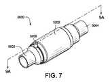
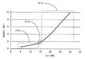
図7に示したような本技術の1つの形態において、空気流が患者の気道の入口に送出される前に、周囲空気(患者周りの空気)に関して空気流の含水率または絶対湿度を上げるための加湿器5000が提供されている。加湿器5000は、空気導管4170を経由して、空気流を受け取るためのRPT装置4000に直接または間接的に連結されるように構成される。加湿器5000は、RPT装置4000の上流または下流に置いてよい。1例では、約70%から90%の相対湿度、例えば80%相対湿度で、約25oCから30oC、例えば27oCの加湿された空気の流れを吐出することができる。In one form of the present technology, as shown in FIG. 7, to increase the moisture content or absolute humidity of the airflow with respect to ambient air (air around the patient) before the airflow is delivered to the entrance of the patient's airway.
加湿器5000は、空気流を受け取る空気入口5002と湿度を上げた空気流を吐出する空気出口5004から成ってよい。
5.5.2 加湿器のコンポーネンツ
5.5.2.1 リザーバ5110
5.5.2 Humidifier components
5.5.2.1
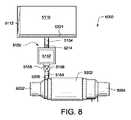
本技術の1態様に従い、加湿器5000は図8に示すリザーバー5110を含む(または連結する)ことができる。リザーバー5110は、空気流の絶対湿度を上げるのに使用する水(または薬物、香り付け剤またはこのような添加物を含む混合物)の所定の最大量を保持するように構成してよい。 According to one embodiment of the present technology,
1形態において、リザーバー5110は、少なくとも1日に患者が睡眠中に使用する数百ミリリッターの水を保持するように構成してよい。しかしその他の形態では、可搬の旅行用の小さなリザーバーまたは病院システム用の大きなリザーバーのようなその他のサイズも適している。さらに、リザーバー5110は水道に替えたりまたは水道に接続することができる。 In one form, the
いくつかの配置によれば、リザーバー5110は水量検出器5112を含めるかまたはこれに連結することができ、これによりリザーバー5110中の水量を決めることができる。水量検出器5112は、1つまたはそれ以上の存在する人、重量、光学特性、超音波特性またはリザーバー5110の水のヘッド(高さ)の1つまたはそれ以上に基づいて水の容量を決めることができる。例えばPCT特許出願番号PCT/AU2014/050286に記載されているメカニズムまたは方法のいずれも本技術で使用するのに適切なものである。この全文を相互参照としてここに包含する。 According to some arrangements, the
いくつかの形態では、例えば図8に示すようなリザーバー加熱エレメント5221を含めるかまたはこれに連結して、水が加湿器チャンバー5200に入る前に水を加熱するようにリザーバー5110を構成してよい。 In some forms, the
1つの形態において、例えばそれぞれのチャンバーが異なる液体を含むなど、リザーバー5110は複数の液体チャンバーを含んでよい。1例において、第1のチャンバーは水を含み、第2のチャンバーは薬物(例えば、液中に溶かしたもの)または香り付け剤(例えばティーツリー油)を含んでよい。複数の液体チャンバーからの液体は、加湿器への吐出の前またはその間に混合するするかまたは加湿器5000の中で混合してよい。代案として、加湿器は複数の液体チャンバーから液体の1つを任意の時間に吐出することができる。
5.5.2.2 水吐出メカニズム5150In one form,
5.5.2.2
本技術の1態様によれば加湿器5000は、リザーバー5110から加湿チャンバー5200へ水の流れを吐出する水吐出メカニズム5150を含んでよい(図8参照)。水吐出メカニズム5150は、水ポンプ5152と水吐出導管5154を含んでよく、水の流れを加湿チャンバー5200へ吐出する水供給入り口5206と流体接続とすることができる。水吐出メカニズム5150は追加でまたは代案として、1つまたはそれ以上の流体チャネル、毛細管チャネルまたは穴を含んでよい。水吐出メカニズム5150はある形態では、リザーバー5110から加湿チャンバー5200への水の吐出を制御するためにさらにバルブ(例えば、水チェックバルブ5158)を含んでよい。ただし水供給入り口5206への水の吐出を許可しかつ防止するものでなければならない。例えばこのバルブは、加湿器が運転中にのみ水の流れがリザーバー5110から加湿チャンバー5200へ移るように制御的に許可するように構成してよい。 According to one aspect of the present technology,
加湿チャンバー5200は、水吐出メカニズム5150からの水の流れを受け取る加湿器ウイック5230のような水保持機能を含んでよい。いくつかの形態では、加湿器ウイック5230中の水の分布をよりよく制御するために(例えばより均一に)、加湿器5000は複数の水吐出メカニズム5150および/または複数の水供給入り口5206を含むことができる。この開示では、明示的に特記のない限り、水の流速はリザーバー5110から加湿チャンバー5200までの水の平均流速を意味する。 The
加湿器5000が提供するように構成されている流速(複数)は、加湿器5000の構成、周囲条件(例えば、周囲温度/湿度)のような期待される運転条件の範囲、加湿器の運転パラメータ(例えば、加熱エレメント5220の最大熱出力、加湿器ウイック5230の最大水容量)および/または治療条件(例えば、治療圧力、空気流速、患者の快適さ/好み)のようないろいろなファクターで変動する。例えば、治療圧力の変更は水の流速の変更のみ生じ、これは加湿器コントローラー5550による応答によるものまたは水の吐出メカニズム5150の特性によるものなどである。 The flow rate (s) that the
1形態において、加湿器5000が提供できる水の流量の範囲は0ml/分から2ml/分、例えば0ml/分から1ml/分または0ml/分から0.5ml/分である。1形態において、加湿器5000は多数の離散的水流量の1つを提供するように構成でき、例えば0.0ml/分、0.2ml/分、0.4ml/分、0.6ml/分または0.8ml/分で、提供出来る水の流量の上限と下限は0.0ml/分と0.8ml/分である。ほかの形態では加湿器5000は、流量のアナログ制御を提供することによって上限と下限の間の任意の流量を提供できるように構成できる。水流量の上限と下限は、最大湿度出力、加湿器を通る空気の最大流量、加湿器のサイズおよびウイックの特性(例えば、露出表面積および/または水容量)の1つまたはそれ以上の加湿器の態様によって変動する。少なくとも1つの水以外の(または水に加えて)液体を使用する場合は、それぞれの液体の流量はそれに応じて変動する。加湿器5000の運転中の特定の時間における流量も、特定の時間における一式の運転条件に依存する。例えば、空気流量が35l/分で所望の追加湿度が15ml/分の場合、0.5ml/分の水が必要になる。 In one embodiment, the range of water flow rate that the
呼吸治療における空気流量は、例えば患者の呼吸サイクルのため短期間で変動することに注意されたい。しかし空気流量に基づいて適当な水の流量を決定するなどのいくつかの例では、加湿器のアルゴリズムは空気流量を利用でき、この場合このような変動の影響を取り除くかまたは低減される。このようにして空気流量はローパスフィルターを通すかまたは連続平均に基づいてよく、この場合時定数(例えば、フィルタリングにおけるまたは平均時間)は呼吸変動の影響を低減するかまたは取り除くために十分に長くなる。 Note that air flow in respiratory therapy fluctuates over a short period of time, for example, due to the patient's breathing cycle. However, in some instances, such as determining an appropriate water flow rate based on the air flow rate, the humidifier algorithm can utilize the air flow rate, in which case the effects of such fluctuations are eliminated or reduced. In this way, airflow may be low-pass filtered or based on a running average, where the time constant (eg, in filtering or averaging time) is long enough to reduce or eliminate the effects of respiratory variability. .
RPT装置における空気の流れの圧力(空気圧としても知られる)とその下流の空気路の圧力は、例えば4から30cmH2Oの間で治療中に変動することがある。したがって水ポンプ5152は、加湿器5000におけるいろいろな空気圧力に対して一貫性のある水流量を吐出するように構成してよい。水ポンプ5152によって提供される水流量は、加湿器5000における空気圧とは無関係(即ち影響を受けない)であってよい。このような水ポンプ5152は、空気圧は治療システムの制御性の改善のためにそこに提供された加湿の量とは無関係に変動するという点で有利である。The pressure of the air flow (also known as air pressure) in the RPT device and the pressure of the air passage downstream thereof may fluctuate during treatment, for example, between 4 and 30 cm H2 O. Accordingly,
1形態において、水ポンプ5152容積式ポンプであってよい。もう1つの形態において、メーター性ポンプ、蠕動ポンプ、自重送りのポンプまたは送風機の圧力を利用するポンプなどのそのほかの多くのタイプのポンプを水吐出メカニズム5150で使用するのに適切である。ドリップバッグのような高架水槽(図示せず)も適しており、水を吐出するのに自重送りのポンプとして作動する。 In one form, the pump may be a
ポンプ5152を通る水の流量が空気圧の影響を受けることがあるいくつかの形態では、水ポンプ5152を通る流量はそれに応じて補正することができる。例えば図8に示すように水吐出メカニズム5150は、追加で1つまたはそれ以上の測定するための計量メカニズム5156および/または水ポンプ5152を通る水の流量を制御するための水チェックバルブ5158を含むことができる。代案として加湿器コントローラ5550を、空気圧力に従って水ポンプ5152を制御して空気圧力の任意の変化の影響を補正するのに使用できる。このような制御を可能にする入力として、空気圧力の測定値を加湿器5550が受信できる。いくつかの形態では、水吐出メカニズム5150を通る水流量を制御することによって、空気流量の任意の変化(例えば、漏れの変化によるもの)を補正するのに加湿器5550を使用することができる。 In some configurations where the flow of water through the
もう1つの配置(図示せず)では、RPT装置4000で生成された圧力を利用することによって水を汲み上げるように水ポンプ5152を構成してよい。こうすれば水をリザーバ5110から加湿チャンバー5200へ汲み上げるのに圧力を使用できる。このような配置における水の流量は空気量の関数であり得て、この配置における加湿器5000は水の流量を調節する制御弁をさらに含めることができる。 In another arrangement (not shown),
いくつかの形態では、加湿器5000は以下に詳細を説明する水吐出メカニズム5150における閉塞またはリザーバ5110における水の不足のような状態を検出する故障検出メカニズムを含んでよい。例えば、容積型ポンプに閉塞が生じるとモータが失速し、ポンプは停止してしまう。さらに加湿器5000は、例えばウイック5230における沈殿物の堆積および/または汚染を検出するように構成してよい。堆積または汚染は加湿器5000の性能に逆影響を与え、水を吸収するウイック5230の能力を下げる。
5.5.2.3 加湿チャンバー5200In some embodiments,
5.5.2.3
1態様によれば、加湿器5000は加湿チャンバー5200を含めることができ、ここでは空気流に水分を加えて、患者1000に供給する前に絶対湿度を上げる。図9Aにその断面を示す1形態では、加湿チャンバー5200は加湿器ウイック5230、水供給入口5206および加熱エレメント5220を含むことができる。 According to one embodiment, the
加湿チャンバー5200は、水供給入り口5206を通してリザーバ5110と流体接続または水を受け取るようにしてよい。水供給入り口5206は、ある形態では0.5mmから3mmの間の例えば1mm、2mmまたは2.5mmの内径を含めることができる。水供給入口5206は、例えば汚染物質の蓄積による水供給入口5206の閉塞のリスクを低減するように十分大きくすることができる。 The
1形態において、加湿チャンバー5200は外への断熱を行い、同時に加湿チャンバー5200の内部、内部にあるコンポーネンツを保護するように構成された外側ハウジング5202を含むことができる。外側ハウジング5202は、一緒に連結された入り口部5202a、ヒーターのカバー部5202bおよび出口部分5202cのような複数の部分を含めてよい。入り口部5202aは空気入口5002を含むことができ、出口部分5202cは図9Aに示すように空気出口5004を含めてよい。水供給入り口5206は入り口部5202aの中に位置するように示されているが、任意の部分5202a、5202b、5202cに位置してよい。複数の水供給入口5206がある場合は、追加の水入口5206は外側ハウジング5202の1つまたはそれ以上の部分5202a、5202b、5202cの中に位置する。ヒーターカバー部5202bは、加熱エレメント5220にあり、それを保持するように構成されてよい。いくつかの配置では加熱エレメント5220は、図9Aに示すように内部ハウジング5204と外部ハウジング5202のヒーターカバー部5202bの間に保持することができる。加熱エレメント5220は、加熱エレメント5220と加湿チャンバー5200間の熱伝導の改善のいくつかの形態において、内部ハウジング5204に固着してよい。内部ハウジング5204は、加熱エレメント5220を水分に暴露されるのを隔絶するように、それでも加熱エレメント5220から加湿器ウイック5230へ熱の伝達ができるように、構成される。 In one form, the
図9Bは本技術によるもう1つの形態における加湿器5000を示す。この形態では、例えば断熱のために空隙を作るために、外側ハウジング5202のヒーターカバー部5202bを加熱エレメント5220から離して設置する。ヒーターカバー部5202bも、図9Bに示すように水供給入り口5206を囲んでよい。 FIG. 9B shows a
内部ハウジング5204に適した材料は、熱的に伝導性のある材料、例えばアルミとその合金また熱的に伝導性のある重合体/熱可塑性の材料、例えば熱伝導率の改善のためのガラスまたはカーボン充填でできたポリカーボネート/アクリロニトリル・ブタジエンスチレン(PC/ABS)、ポリアミド(例えば、ナイロン)またはポリフェニレン硫化物(PPS)が含まれる。内部ハウジング5204は、加湿器5000に剛性を与えるのに適した硬い材料でよい。ただしある形態では、加湿器のそのほかの材料が十分な構造的剛性を提供する場合には可撓構造を使用できる。外側ハウジング5202に適した材料には、PC/ABSのような重合体材料が含まれ、外側ハウジング5202は熱可塑性のエラストマー(TPE)のようなエラストマー部を含むことができる。外側ハウジング5202は、10mmから50mmの直径と約1〜3mmの厚さとしてよい。内部ハウジング5204の厚さは、約1〜3mmで使用する材料によって、例えば十分な熱伝導率を達成するために、変動してよい。このような寸法と配置は1例であり、制限する意図のないことを理解されたい。内部ハウジング5240および/または外部ハウジング5202は、示したものと異なる形状および/または異なる部分数、例えば1つ、2つ、4つ、5つまたはそれ以上の部分に形成してよい。 Suitable materials for the
1つの態様によれば、水供給入り口5206は、図8に示すように水を加湿器ウイック5230に吐出するように水供給メカニズム5150と流体連絡としてよい。ある場合には加湿器5000は、外雑物の加湿チャンバー5200へのおよび/または水の流れからウイック5230中への侵入を低減するように構成されてよい。水フィルター5214は、(図8に示すように)リザーバ5110の出口またはその近くに、または水供給入り口5206の上流(その前に)に位置することができる。水フィルター5214またはそのパーツは、交換可能かまたは掃除できるように構成してよい。いくつかの形態では(例えばリザーバ5110中の水質が低いおよび/またはリザーバ5110中の水の硬度が高い)、水フィルター5214は純水装置(図示せず)を含めてよい。 According to one embodiment, the
いくつかの配置では(図示せず)、水供給入り口5206は空気入口5002よりも空気出口5004に近づけて位置してよい。このような配置では、ウイック5230における水の流れの少なくといくつかの部分が、加湿チャンバー5200における空気流の方向と反対方向に流れるように仕向けられる。このようにしてウイック5230の中のまた空気流の中の水の温度と湿度の勾配が最適化され、その間の温度差と湿度差が最適化されて加湿性能が改善される。 In some arrangements (not shown), the
もう1つの態様によれば、加湿チャンバー5200は、例えば加湿性能を改善するために、空気流が加湿チャンバー5200内にある間、長さおよび/または滞留時間を延長して、流れの中の乱流を促進し、および/または蒸発表面積を大きくするように構成された空気流バッフル5208(図9A,9Bおよび図10)をさらに含めることができる。1形態において空気流バッフル5208は、加湿チャンバー内を移動する空気の通路を伸ばすために、図10に示すらせん形のような曲がりくねった通路を通るように空気の流れを強制する。このようにして、空気流バッフル5208は1つまたはそれ以上のバッフルエレメントで構成され、それぞれが1つまたはそれ以上のらせん、傾斜、曲面または乱流を増やしおよび/または加湿チャンバー5200における空気流の通路を伸ばすように配置される。例えば、空気流バッフル5208は加湿チャンバー5200を通る空気流の通路の長さを、加湿チャンバー5200の直線部の長さと比較して約20%から約1000%の間で長くできる。換言すれば、バッフル5208がないと加湿チャンバー5200を通る空気流は、入口5002から出口5004まで直接またはリニアに通ることができる。しかしバッフル5208を追加すると、入口5002から出口5004まで加湿チャンバー5208を横切るために空気の流れが通らなければならない通路の抵抗または長さが増すことになる。例えば、通路の長さは約50%から約750%、約100%から約300%のように、約200%のように長くなる。本技術のいろいろな実施例において、空気流バッフル5208で長くなる量は、加湿器5000の特定の配置および/または要求事項によって変動することが理解されよう。 According to another embodiment, the
加湿チャンバー5200に空気流バッフル5208を包含すると、空気流バッフル5208なしに使用する加湿チャンバー5200における。空気流の通路の長さと比較して、加湿チャンバー5200の長さなどサイズが小さくなるのに役立つ。代案としてまたは追加で、加湿チャンバー5200はさらに1つまたはそれ以上の空気流トリップエレメント5209を蒸発面に沿って含むことができる。この空気流トリップ5209は空気流の乱流を増すことによって加湿性能を改善するように構成されている。空気流トリップエレメント5290(本明細書中で‘トリップエレメント’と称する)は、例えば持ち上げたステップまたは表面のように、空気流に対する障害を含むことができる。トリップエレメント5209は(例えばレイノルズ数で測定されるように)乱流の量を増やすことができ、これにより境界層の厚さが薄くなり、加湿器ウイック5230から空気流への水分の移送を促す。いくつかの形態では、トリップエレメント5209は空気流の方向に実質的に垂直な方向に空気流に対する障害をもたらすことができる。トリップエレメント5209の1例は図33に示すように、内部ハウジング5204の内部周辺上に位置する輪状のプリズム構造である。 Including the
本技術のいくつかの形態において、空気流バッフル5208はメンブレンを含む。空気流バッフル5208は例えば同調チャンバー(または共鳴装置)の形状、または層流の発達を促しノイズを下げるように構成された多数の狭い流路のようにノイズ低減のための音響エレメントをさらに含んでよい。1形態において、空気流バッフル5208で形成された流路は、反射されたノイズの低減を支援する高イナータンスを提供するよう構成されてよい。いくつかの配置において、空気流バッフル5208には、ノイズおよび/または振動を低減するための可変の減衰特性を含めてよい。 In some aspects of the present technology, the
いくつかの配置において、加湿チャンバー5200は空気流が加湿チャンバー5200を通過するときのの1つまたはそれ以上の特性を検出するためのバイパスポートを含めてよい。 In some arrangements, the
追加でまたは代案として加湿チャンバー5200は、患者の吸入相に対して空気流に湿度を加えるのみに構成されてよい。1形態において例えばバルブを使用して、少なくとも呼吸サイクルの一部に対して加湿チャンバー5200から空気流を方向転換させるのに使用できるバイパス路を含むことができる。これにより例えば呼気の間、呼吸サイクルのある期間加湿なしで患者インタフェース3000に空気流を送出できる。
5.5.2.3.1 加熱エレメント5220Additionally or alternatively, the
5.5.2.3.1
空気の流れがベーパーの形で保持できる水分の量すなわち絶対湿度は、空気の流れの温度によって変動する。 The amount of moisture that the air flow can hold in vapor form, ie, the absolute humidity, varies with the temperature of the air flow.
場合によっては、加湿器5000が受け取った空気の流れは、患者1000の気道の入口へ送達する適切な絶対湿度を保持するには冷たすぎることがある。さらに冷たい空気を送出すると、上記のように患者1000に不快感を生じることがある。このように加湿器5000には、例えば空気の流れを加熱するために熱を出力するように構成された加熱エレメント5220を含めてよい。1形態において、加熱エレメント5220は図9Aに示すように内部ハウジング5204と外部ハウジング5202の間など、加湿チャンバー5200内に位置してよい。代案としてまたは追加でリザーバー5110は、図8に示すように水が加湿チャンバー5200に入る前に水を加熱する加熱エレメント5221を含めてよい。 In some cases, the airflow received by
加熱エレメント5220は、空気が加湿器5000を通過する時に空気の流れを加熱でき、また加湿器ウイック5230を加熱するなどして加湿チャンバー5200内の加湿を支援する。したがって加熱エレメント5220は高い要求度(即ち周囲空気が冷たく、乾燥している時)の加熱と蒸発にそれぞれ十分な熱エネルギーを提供するように構成される。 The
加熱エレメント5220は、上記の要求事項を満足する多数の方法のうちの1つに構成できる。1形態において加熱エレメント5220は、最大40ワットの熱出力を発生する約10cm2の表面を含む。もう1つの形態において、加熱エレメント5220は同じ最大40ワットの熱出力を持った約40cm2の表面積を含む。最大熱出力値は40ワットに限定する必要はなく、加熱エレメント5220の表面積は加湿器5000の態様、例えば最大熱出力、サイズおよび/または形状に従って配置してよい。例えば、加熱エレメント5220は約5から100cm2の間、約10から60cm2の間、約20から40cm2の間のサイズの表面積を含む。加湿器5000の出力間の関係の例が図17と図19に示されており、加えた湿度と加熱エレメントの温度との関係の例が図18に示されている。サイズおよび/または加熱エレメント5220の熱出力は、本技術の特定の実施例において変動することがあることを理解されたい。例えば加熱エレメント5220は、低加湿および/または熱を送出するように構成された加湿器5000におけるよりも高加湿および/または熱を送出するように構成された加湿器5000において大きい。いくつかの形態では、大きな表面積の加湿チャンバー5200の加熱エレメント5220は、小さな表面積の加湿チャンバー5200より大きくなる。The
本技術の1態様によれば、加熱エレメント5220は区分(ゾーン化)することができる。すなわち、加熱エレメント5220は直接制御できるかおよび/または可変の特性を有する複数のセクションまたはゾーンから成ってよい。ある場合には、ゾーンの可変の特性は形状、熱出力、断熱性、ウイック5230への近接または水供給入口5206への近接を含む。さらに、それぞれのゾーンは加湿器コントローラ5550で互いに独立して制御可能で、場合によっては互いに関連して制御される。ゾーンの相対制御のできる加熱エレメント5220の例が図11に示されている。この例では、加熱エレメント5220は4つのゾーン5220_1、5220_2、5220_3および5220_4から成り、各ゾーンの加熱出力は加熱エレメント5220の合計熱出力の0から100%の間で、たとえば加熱エレメント5220の合計熱出力の0%、10%、20%、30%および40%で変動するように構成される。加熱ゾーンの数は2、3、5またはそれ以上のように異なる数であってよく、形状、サイズまたは最大熱出力のようなゾ−ンの特性は変動することがある。ゾーンはある形態で離間できるが、各ゾーンは互いに隣接してよい。場合によっては、各ゾーンにおいて変動する加熱出力を達成するために、各ゾーンは電気的に伝導性のある回路の変動する密集度を有する。 According to one aspect of the present technology, the
加熱エレメント5220の1つの適切な形態は、基板上に抵抗性のある電気的トラックを含んでよい。この基板は、抵抗性のある電気的トラックとウイック5230の間に電熱性があり電気的に抵抗性のあるバリアとして使用可能な回路基板を含めてよい。1つの形態において、加熱エレメント5220は可撓の回路基板を含むことができる。もう1つの形態において加熱エレメント5220は、加熱トラックから誘電体層で分離された金属的熱的に伝導性のある基板を含むことができる。加熱エレメント5220の代案の形態も、加熱エレメント5220がウイック5230および/または加湿チャンバー5200へ熱出力を提供できるように構成されているのであれば誘電ヒーターとして適している。 One suitable form of the
加熱エレメント5220の基板も少なくとも加湿器ウイック5230の一部を含むことができる。このようにして基板は、紙、フェルト、織って作った材料または任意の薄い吸収剤膜のような1つまたはそれ以上の吸収性材料を含むことができる。電気回路は基板上に配置して、印刷による、化学結合による、接着剤によるまたは織り交ざりによる抵抗性のある電気トラックを提供することができる。1つの形態において、導電性の材料を含む導電性インクを吸収性基板上に印刷できる。それにより導電性回路が吸収性基板の表面に形成される。 The substrate of the
導電回路は、本明細書のどこかに記載されている1つまたはそれ以上のセンサーに接続できる。追加でまたは代案として導電回路は、パラメータによって電気抵抗が変動する変動抵抗部分を含むことができる。変動抵抗部分の例には正の温度係数部分または負の温度係数部分を含めてよい。変動抵抗部分は、変動抵抗部分におけるまたはその近くの温度をその抵抗の変化により検出するなど、検出エレメントとして使用できる。正の温度係数(PTC)部分は、PTCカーボン・インクを紙の基板上に印刷することによって吸収性基板上に配置できる。 The conductive circuit can be connected to one or more sensors described elsewhere herein. Additionally or alternatively, the conductive circuit may include a variable resistance portion whose electrical resistance varies according to a parameter. Examples of the variable resistance portion may include a positive temperature coefficient portion or a negative temperature coefficient portion. The variable resistance portion can be used as a sensing element, such as detecting a temperature at or near the variable resistance portion by a change in its resistance. The positive temperature coefficient (PTC) portion can be placed on an absorbent substrate by printing PTC carbon ink on a paper substrate.
いくつかの形態においては、吸収性基板に配置された任意の導電部分を絶縁するために電気的絶縁体を吸収性基板上に配置できる。例えば、誘電インクを含む絶縁層を印刷して、紙の基板上に印刷された導電性インクを含む導電回路を絶縁する。 In some forms, an electrical insulator can be disposed on the absorbent substrate to insulate any conductive portions disposed on the absorbent substrate. For example, an insulating layer containing dielectric ink is printed to insulate conductive circuits containing conductive ink printed on a paper substrate.
もう1つの形態において加熱エレメント5220の抵抗性のある電気トラックは抵抗性ワイヤーを含む。この抵抗性ワイヤーは図20に示すように、例えば表面の周りに複数のループを形成して外側ハウジング5202の周りに巻きつける。1実施例において、ワイヤーのそれぞれのより糸は接着剤(例えばエポキシ)でワイヤーの隣接するより糸(複数)に固着してよい。もう1つの実施例では、ワイヤーの各より糸は絶縁層を含んでよく、熱がそこに加えられたとき隣接するより糸(複数)に固着するように構成されてよい。このように抵抗性ワイヤーの複数のループを外側ハウジング5202の周りに形成でき、熱は加熱エレメント5220に加えられ(例えば、外側にまたは加熱エレメント5220を通して電流を加えて)より線を共に固着する。 In another form, the resistive electrical track of
上記のように、加熱エレメント5220は形状および/または構造における多数の可能な形態の1つをとることができる。加熱エレメント5220は(例えば図9Aと図11において)円筒形状となっているが、このような形状に限定する必要はないことを理解されたい。例えば、加熱エレメント5220はとりわけ平らな、長方形のシート、押し出し円弧形状、長方形プリズムまたは複数の並列シートの形で構築できる。 As mentioned above, the
加熱エレメント5220は場合によっては使い捨てである。例えば、加湿チャンバー5200全体を使い捨てとでき、この場合加熱エレメント5220は、使い捨てコンポーネントの一部として加湿チャンバー5200内に一体として形成される。代案として、加熱エレメント5220は使い捨てとし、加湿チャンバー5200から取り外すことによって容易に交換できるよう構成される。例えば、据付のために加湿チャンバー5200の中へ滑り込ませて挿入する。
5.5.2.3.2 加湿器ウイック5230The
5.5.2.3.2
本技術の1態様として、加湿器5000は加湿器ウイック5230のような水保持機能を含んでよい。水保持機能(例えば加湿器ウイック5230)は水量を保持するように構成されており、水はリザーバー5110から受け取り、蒸発させて空気流が患者1000に吐出される前に加湿する。水保持機能は、RPT装置4000から患者インタフェース3000までの空気通路の一部をそれが実質的に規定するように成形される。水保持機能は、例えば円筒形の通路など実質的に囲まれた通路を形成することによって空気通路の一部を規定できる。換言すれば水保持機能は、加湿器5000を通る空気の流れのための流路の少なくとも一部を囲むまたは実質的に囲むことができる。 In one aspect of the present technology,
例えば水保持機能、例えば加湿器ウイック5230は空気の流路の少なくとも一部を軸方向に囲むまたは実質的に囲むような輪郭の形状を持つことができる。図7〜10、12〜16および31〜34に示す例では、加湿器ウイック5230は実質的に円筒断面の形状に輪郭を形成されたと理解してよい。しかし加湿器ウイック5230はU-型断面、V-型断面、長円形、楕円または楕円断面、多角形断面(即ち、加湿器ウイック5230の内部が囲まれている限り断面は任意の数の側面を持つことができる)または放物線形状の形の輪郭形状を持つことができることも理解されたい。加湿器ウイック5230は、加湿器ウイック5230の内部およびその中の流路の少なくとも部分を完全に囲む輪郭の形状、例えば円断面、長円形、楕円または楕円断面、多角形断面を持ってよいことも理解されたい。代案として、加湿器ウイック5230は加湿器ウイック5230の内部およびその中の空気の流路の少なくとも部分を完全に囲まない輪郭の形状、例えばU-型断面またはV-型断面を持ってよい。 For example, a water retention feature, such as a
本技術の1例において、加湿器ウイック5230はそこを通る空気の流れに直接接触する表面を規定する輪郭形状を持ってよく、その表面は実質的に平面でない輪郭形状を有している。換言すれば、表面は実際は3次元で、2次元ではない。 In one example of the present technology, the
サイズの小さい加湿器5000を維持しながら、加湿出力の目標レベルを達成するために、水保持機能が空気流との接触面積を最大にする空気路の一部を全体的に規定することは有益である。このようにすると、水保持機能が空気路の周辺の周りに全体的に配置され、水保持機能の一定の長さに対して空気路と水保持機能間の接触面積が最大になる。例えば、図10に示す加湿器ウイック5230は、円筒形状の加湿チャンバー5200の中に適合するように中空円筒の形をしており、円筒形状、囲まれた空気路を画成する。ほかの形状ももちろん適していることは理解されよう。 In order to achieve the target level of humidification output while maintaining a
加湿器ウイック5230に保持できる最大水量または加湿器ウイック5230の水容量は事前に決めることができる。1態様において、加湿器ウイック5230の水容量を十分に少なくして、加湿器5000の応答時間を短くする。すなわち、加湿器5000はその出力(例えば、湿度および/または温度出力)への変更を比較的短時間にもたらすことができる。加湿器5000の応答時間は、加熱された水量の関数であることは当事者によって理解されよう。このように、本技術による加湿器5000は比較的短い応答時間とすることができる。本技術のいくつかの形態において、加湿器5000の熱および/または湿度出力は、45秒、30秒または15秒以内のように約1分以内に変動するように、十分に短い応答時間で構成される。 The maximum amount of water that can be held in the
もう1つの態様によれば、最大の流量と最も乾燥した周囲条件において適切な加湿を行うために、加湿器ウイック5230の水容量は十分に大きい。ある形態では、加湿ウイック5230はそこに含まれた水が加湿器5000を通る空気流と接触できるように適切な大きさの表面積を含む。加湿器ウイック5230の水容量は約10グラム(g)であるが、約2g、6g、15g、20g、30gまたはこれらの値の間のそのほかの値も適切である。そのほかの形態において、加湿器ウイック5230のより大きいまたはより小さい容量は、加湿器のサイズと適用に依存して適切である According to another embodiment, the water capacity of the
加湿器ウイック5230の水容量が加湿器ウイック5230における水含有量と同じである状態は、ウイック5230の‘飽和’または‘洪水’と言う。ある場合には加湿器5000は、使用中に加湿器ウイック5230が飽和しないように運転される。加湿器ウイック5230が引き起こすデメリットには、加湿器ウイック5230から吸収されなかった水が移送されて(例えば空気流への取り込み)加湿器5000および/または空気回路4170への水滴の持ち込みが含まれる。このように加湿器ウイック5230の飽和の検出が望ましく、以下に詳細を説明する。いくつかの場合には、このような移送に関連した任意の可能性を改善するために、例えば移送されたすべての水または凝縮を吸収して、空気回路4170はウイック5230の一部または第2のウイック(または水トラップ)を含むことができる。 The condition where the water capacity of the
1つの態様によれば、ウイック5230は不均質配置および/または構造で(例えば、異方的にまたはゾーンで)構築してよい。このように水容量、空気に露出した表面積または熱伝導率のようなウイック5230の1つまたはそれ以上の特性は、ウイック5230の各領域に対しまたは方向によって変動する。例えば、ウイック5230は空気流の方向に沿ってまたは水供給入口5206からの距離に沿って不均質で、ウイック5230の厚さが変動することがあり、ウイック5230は水供給入口5206から離れるとそれだけ薄くなる。1つの形態において、ウイック5230の配置は、深さ、層の数、密度および/またはウイック5230の材料の1つまたはそれ以上で変動する。 According to one embodiment,
例えば加湿器ウイック5230は、図12に示す第1の層5230aと第2の層5320bの1つまたはそれ以上の層を含む。1つまたはそれ以上の層は、形態および/または機能において異なる。1つの例において、第1の層5230aは水供給入口5206と連絡する移送層で、第2の層5230bは第1の層5230aの上に置かれた蒸発層で、空気流と接する。この構造において、第1の層5230aは容量当たりの水および/または水の速い移送を最適化するように構成され、そして第2の層5230bは例えば、容量当たりの露出された表面積を増すことによって、改善された蒸発特性に対して構成される。いくつかの形態において、加湿器のウイック5230は1つまたはそれ以上の層が互いに独立して置き換えられるように構成でき、そこで1つまたはそれ以上の層は形態および/または機能において同じまたは同じでなくてよい。 For example, the
1つの形態において加湿器のウイック5230は、ウイッキングの率が第2の方向におけるより第1の方向において大きいように構成される。このような構造にすると、水の配分に所定の態様でバイアスがかかる。例えば加湿器のウイック5230は、空気流に垂直な方向におけるウイッキングの率が、空気流と平行な方向におけるウイッキングの率より大きくなるように構成される。このような構造は、空気流のより多くの異なる部分が加湿器のウイック5230と接触するようになるので、空気流の加湿の率を最大にするのに有利である。加湿器のウイック5230は、空気の流れの方向に対して例えば30度、60度または90度のような1つまたはそれ以上の方向に異方性を持つように構成される。 In one form, the
いくつかの形態では、加湿器のウイック5230は、空気の流れに露出した合計表面積が増加するように構成された表面を含む。こうすれば加湿器のウイック5230によって保持された水が空気流と接触する面積が増し、加湿効率が改善される。例えば、加湿器のウイック5230は図13に示すように波型の内部表面を含むことができる。そのほかの適当な表面のタイプとして、1つまたはそれ以上のくぼみ型、穿孔型、多孔型, 織った、編んだ、織り目加工された、焼結された表面がある。 In some forms, the
本技術による加湿器のウイック5230は、単一の連続コンポーネント、アセンブリとして働く複数のコンポーネンツまたは不連続で離散的なウイッキング材料の集まりおよび/またはエレメントを含む。本明細書では、すべてまたは任意の上記のバリエーションを‘加湿器のウイック’5230と呼ぶ。加湿器のウイック5230はウイッキング材料の単一のピースとして構築される必要のないことを当事者は理解するであろう。 A
加湿器のウイック5230は図9Aの例に示すように、加湿器5000の外周に向けて位置してよい。図9Aでは加湿器のウイック5230は加湿器5000を通る空気通路の外側の境界の少なくとも一部を形成するように示されている。追加でまたは代案として、加湿器ウイック5230は図32に示すように加湿器5000の中心に向けて位置し、加湿器ウイック5230は加湿器5000を通って空気流路の外側境界から離して位置する。図32に示した構成において加湿器5000は、加湿器ウイック5230をその意図した場所に位置させおよび/または確保するために1つまたはそれ以上のウイックつっぱり5231を含む。1形態において、1つまたはそれ以上のウイックつっぱり5231は、図32に示すように加湿器ウイック5230を内部ハウジング5204に関して、加湿器ウイック5230を位置しおよび/または確保するように、内部ハウジングに取り外し可能にはめ込まれるように構成される。 The
いくつかの形態では(例えば加湿器ウイック5230が加湿器5000の中心に向けて位置している)、液体をリザーバ5110から吐出するために、水供給入口5206が、図32に示すように加湿器5000の内部表面から加湿器ウイック5230に向けて伸びている突起を含む。水供給入口5206は図32に示すように導入部5207を加湿器5230の挿入方向へ追加で含み、加湿器ウイック5230の加湿器5000への挿入中に自己位置合わせ出来るようにする。 In some configurations (e.g.,
もう一つの態様によれば、例えば加熱エレメント5220によって加湿器ウイック5230を加熱することができる。加熱されたウイック5230の1つの利点は、蒸発率を制御できることである。1形態において、加熱器ウイック5230は、例えば図12に示すように接触によって加熱エレメント5220に熱的に連結できる。これは加湿器ウイック5230と加熱エレメント5220間の熱的インピーダンスを有利に下げることができる。 According to another embodiment, the
加湿器ウイック5230はある場合には、加湿器ウイック5230と部分的に熱接触している加熱エレメント5220によって部分的にのみ加熱される。1つの形態において加湿器ウイック5230は、加熱エレメント5220の上流および/または下流の非加熱領域並びに加熱エレメント5220と熱的接触している加熱領域を含む。加湿器ウイック5230の加熱領域5230Hは加熱エレメント5220にオーバーラップしてよく、上流の非加熱領域5230Uおよび下流の非加熱領域5230Dは加熱領域5230Hの上流と下流にそれぞれ伸びている。ここでは加熱エレメント5220にオーバーラップしていない。上流非加熱領域5230Uおよび/または下流非加熱領域5230Dも、加湿器5000の任意の伝導部分、図34に示す内部ハウジング5204ような加熱エレメント5220と密接な熱接触にある、と実質的にオーバーラップしていない。
上流非加熱領域5230Uは、水供給入口5206によって吐出された水が、加湿器ウイック5230の加熱された領域5230Hの中に広がるまたは通る前に、上流非加熱領域5230U内に速く広がるように構成される。例えば、上流非加熱領域5230Uは加熱領域5230Hより高いウイッキング率を含むことができる。このような場合上流非加熱領域5230Uの水は、加熱領域5230Hにおける蒸発の発生の前にその中で広がることができる。このように加湿器ウイック5230はその中の水の空間的分布を改善することになり、ここでは水の境界は空気流の方向に垂直な方向、例えば加湿器5000の半径方向、に実質的に一致する。 The upstream
加湿器ウイック5230は下流非加熱領域5230D(図34に示す)を含み、この領域は加湿器ウイック5230からの未吸収の水の移送のリスクを軽減する追加の水保持能力を提供するのに使用される。例えば、下流非加熱領域5230Dは加湿器ウイック5230の加熱領域5230Hが何時も水で飽和されるように働き、追加の容量を提供してオーバーフローするリスクを軽減している。さらに下流の非加熱領5230Dは、空気流によって加熱領域5230Hの下流に取り込まれるおよび/または移送されるかもしれない非蒸発の水分を捕捉することができる。
1つの形態において、上流非加熱領域5230Uの適切な長さは加熱領域5230Hの長さの約5%と約20%の間で、約8%と約15%の間、約8%と約12%または約10%の間である。長さ50mmの加熱領域5230Hを含む加湿器5000では、上流非加熱領域5230Uの適当な長さは約2.5mmと約10mmの間、約4mmと約7.5mmの間、約4mmと約6mmまたは約5mmの間である。1形態において、下流非加熱領域5230Dの適当な長さは加熱領域5230Hの長さの約10%と約50%の間、約20%と約40%の間、約25%と約35%または約30%の間である。長さ50mmの加熱領域5230Hを含む加湿器5000では、下流非加熱領域5230Dの適当長さは約5mmと約25mmの間、約10mmと約20mmの間、12.5mmと17.5mmまたは約15mmの間である。 In one form, a suitable length of the upstream
上流非加熱領域5230Uおよび/または下流非加熱領域5230Dのサイズは、加湿器5000の態様、例えばそのサイズ(例えば長さおよび/または直径)、加湿出力、加湿器ウイック5230のサイズ、加湿器ウイック5230の水容量、水の流速および/または水供給入口5206の数
によって変動する。The size of the upstream
加湿器ウイック5230の性能は、時間と共におよび/または使用すれば低下し、ある場合には加湿器ウイック5230がもはや使用に適しなくなる。例えば水からの微粒子のような外雑物が水が蒸発するときに加湿器ウイック5230上に集まりまたは蓄積する。場合によっては外雑物が溜まると、加湿器ウイック5230の水容量および/または熱伝導率が下がる。ある場合には加湿器5000を全く使用しなくても、加湿器ウイック5230は時間の経過とともに劣化する。さらに加湿器ウイック5230に集められた外雑物が加湿器ウイック5230から出て空気の流れの中に取り込まれることがあり、これは好ましくない。 The performance of the
このように本技術の1態様では、加湿器クイック5230は掃除および/または交換できる。さらに水容量および/またはその残りの有用寿命のような加湿器ウイック5230の1条件を決めることができ、加湿器ウイック5230の交換が必要または取替の時期が来た時、その指示とメッセージを提供する。 Thus, in one aspect of the present technology, the humidifier quick 5230 can be cleaned and / or replaced. In addition, one condition of the
もう1つの態様によれば、加湿器ウイック5230上の外雑物の分布のパターンを決定しおよび/または制御できる。例えば、外雑物が所定のパターンに従って加湿器ウイック5230上に集まるのを助長するように加湿器チャンバー5200を構成できる。さらに外雑物が加湿器ウイック5230上に蓄積する所定のパターンを使用して、加湿器ウイック5230の残りの寿命の指標とすることができる。例えば、外雑物が加湿器ウイック5230の1つの所定の領域から溜まり始めるように、また溜りが所定の方向へ成長するように加湿器ウイック5230を構成することができる。こうすれば、例えば所定の寿命指示領域における外雑物の蓄積の検出を使って、加湿器ウイック5230がもはや使用に適さないことを示唆することができる。このように加湿器ウイック5230が加湿器5000に残ったままで、加湿器ウイック5230の残りの寿命を決定できる。 According to another embodiment, the pattern of foreign matter distribution on the
加湿器ウイック5230を使用中の例の配置を示す加湿器5000の断面を図14に示す(ウイックフィレーム5232は示さず)。この例では、加湿器ウイック5230は水量を保持しているが、水量は加湿器ウイック5230の水容量より少ない。よって加湿器ウイック5230は2つの領域を含むように示されており、水の境界で分けられた湿った領域5230_Wと5230_Dが5230_WBとして示されている。典型的には、水から加湿器ウイック5230への任意の外雑物の生成または蓄積は、大部分が境界端で生じ、ここが微粒子が乾燥するポイントである。よって本技術の態様の1つは、以下に説明するようにウイック5230の構築および/または外雑物管理アルゴリズムを使った水境界5230_WBの制御に関する。 A cross section of the
1形態において、ウイック5230は例えば皿洗い機の中での洗浄、別の薬剤を使っての消毒および/またはマイクロウエーブを使って洗浄できるよう構成できる。追加でまたは代案として加湿器ウイック5230は銀のような殺菌剤または抗菌剤を含むことができる。さらに加湿器5000は以下に説明する自浄アルゴリズム(例えば、汚染微生物数低減アルゴリズム)を含むことができる。 In one embodiment, the
1つの態様によれば、加湿器ウイック5230は、空気流に投入する薬物のような追加の物質または寿命表示装置を含むことができる。寿命表示装置は、変色して加湿器ウイック5230を交換すべきだとユーザまたは患者1000に指示する着色部を含むことができる。加湿器ウイック5230は、蒸発により患者1000に送られる空気流に放出される薬物を含むことができる。 According to one embodiment, the
加湿器ウイック5230に適した材料は、紙、親水性繊維からなる複合材料およびセルロース繊維が含まれるがこれらに限定されない。加湿器ウイック5230は、本明細書に記載の加湿器ウイック5230の特性を発揮するために、上記の材料を1つまたはそれ以上の配置で(例えば、平らな、波型、等方性、異方性、層形状など)含むことができる。 Suitable materials for the
加湿器ウイック5230は、ある場合には加熱エレメント5220を含むまたは組み合わせることができる。本明細書のほかの場所に記載されているように、ウイック5230は加熱のための抵抗性トラック、水の保持のための吸着部(例えば、紙)および伝導部の基質としても働く蒸発部を形成する伝導部分(例えば、カーボンインンク)を含むことができる。1形態において加熱エレメント5220は、内蔵コンポーネントを創るためにウイック5230の片側または両側に連結(例えば印刷)してよい。内蔵コンポーネントは、ウイック5230の片側または両側に連結できる(例えば印刷)1つまたはそれ以上のコネクターをさらに含むことができる。例えばコントローラ5550への接続。 The
加湿器ウイック5230は何らかの形でシートから構築できる。例えば、加湿器ウイック5230は、加湿器チャンバーの形状に適合するような管状形状に形成された紙シートを含むことができる。このシートは接着剤で固着でき、その適当な例はホットメルト・オープン接着ウエブである。しかし多数の既知の接着剤も適していることは容易に理解されよう。 The
加湿器ウイック5230は1つまたはそれ以上の加湿器変換器を含む。加湿器変換器と加湿器変換器から入力を受信する加湿器アルゴリズムについて下記に詳細に説明する。
もう1つの態様において、加湿器ウイック5230は加湿器チャンバー5200に関して容易な挿入および/または取外しができるようにする形状に構築される。1形態において、タブ(図示せず)のような加湿器ウイック5230の一部は、加湿器ウイック5230がその動作位置にある時、取外しのためにアクセスできるよう構築される。さらに加湿器5000は、加湿器ウイック5230へのアクセスができるように(外部ハウジングコンポーネント5202_cなどの)コンポーネントを取外すことができるように図14に示すように構築してよい。追加でまたは代案として、加湿器ウイック5230は、作動位置に挿入する間自ら位置決めするように、加湿チャンバー5200と同様の形状に相補して、円錐台の形状に構築できる。
5.5.2.3.3 ウイックフレーム5232In another embodiment, the
5.5.2.3.3
本技術のいくつかの形態において加湿器5000は、図9A、図9Bおよび図10に例を示したウイックフレーム5232を含むことができる。ウイックフレーム5232はウイック5230に連結され(例えば化学的に固着および/または機械的に連結)、例えばウイック5230を置くおよび/または成形し(例えば予め定められた場所および/または形状に)ウイック5230を加熱エレメント5220に接近して維持し、および/またはウイック5230の変形によって生じる流れインピーダンスの上昇を防止する。ウイックフレーム5232は、ウイック5230をデザイン通りに置くおよび/または成形するのを支援することによって(例えば、ウイック5230を図10に示すように円筒形状に維持することによって)、ウイック5230と加熱エレメント5220の間の熱接触を促進しまたは維持する。図10に示す形態では、ウイック5232は、図示されたショルダーのようにウイック位置決め器5233を含み、ウイック5230を組立品の中のウイックフレーム5232に関して位置決めするのを支援する。 In some forms of the present technology, the
例えばグリップ5232_Gを提供することによってユーザおよび/または患者1000がウイックフレーム5232の挿入、取外しおよび/または取扱うためにウイックフレーム5232を置いたりおよび/または保持するのを支援するために、ウイックフィレームは加湿器5000に関してウイック5230の取外しおよび/または挿入を支援するように構成できる。1形態において、患者/ユーザがウイックフレーム5232を保持できるように、グリップ5232_Gは平らで板状の構成を含むことができる。ただし任意の数のそのほかの形状および/または構成も適切である。グリップ5232_Gは内部ハウジング5204のような周囲のコンポーネントのオープンエンドを通って伸長でき、(例えば加湿器5000の任意のほかのコンポーネンツを分解することなく)加湿器5000の外部からウイックフレーム5232および/またはウイック5230を取り外しできるように、ある形態ではグリップ5232_Gは加湿器5000の外部からアクセス可能である。追加でまたは代案として、ウイック5232は加湿器ウイック5230をバヨネット、ネジ、摩擦嵌合表面またはピンなどで加湿器ウイック5230を取り外し可能に加湿器5000に置くおよび/または固定するコネクター(図示せず)を含むことができる。当事者は多数のそのほかのコネクターも、加湿器ウイック5230を加湿器5000に、例えば外部ハウジング5202に、固定および/または置くのに使用できることを認識するであろう。 To assist the user and / or
グリップ5232_Gは識別のためにマークを付けるか(例えば色および/または指標を使用して)および/またはユーザがグリップ5232_G上に保持するのを支援するためにテクスチャー加工できる。加湿器ウイック5230が使い捨てのいくつかの形態では、例えば加湿器ウイック5230に一体に形成して、ウイックフレーム5232を加湿器ウイック5230と共に配置するよう構成できる。そのほかの場合では、例えばウイックフレーム5232が加湿器5000から取り外している間に加湿器ウイック5230を交換できるように、ウイックフレーム5232は加湿器ウイック5230を受け入れかつ保持するように構成できる。ウイック5232は新しいウイック5230を受け入れ、加湿器5000に挿入できる。いくつかの形態では、ウイックフレーム5232、ウイック5230および加熱エレメント5220を取り外しができないように連結し、ユニットとして使い捨てできるように構成できる。 The grip 5232_G can be marked for identification (eg, using color and / or indicia) and / or textured to assist the user in holding on the grip 5232_G. In some forms where the
もう1つの態様によれば、ウイックフレーム5232は、患者1000がまたは病院または自宅環境で介護者が、3Dプリンターで印刷できるように構成できる。代案としてまたは追加で、ウイックフレーム5232は1つのコンポーネントとしてまたは複数の成形コンポーネンツのアセンブリとして成形できる。いくつかの形態において、ウイック5230とウイックフレーム5232は単一のコンポーネントとしてよい。 According to another aspect, the
1形態においてウイックフレーム5232は、ウイック5230の上流および/または下流にある1つまたはそれ以上の空気フィルターをさらに含むことができる。空気フィルターはウイック5230の上流に置いて、外雑物がウイック5230に入ったりおよび/または蓄積するのを低減する。代案としてまたは追加で、空気フィルターをウイック5230の下流に置いて、外雑物がウイック5230から患者1000に移動するのを低減する。 In one form, the
もう1つの態様によれば、ウイックフレーム5232は上記の空気流バッフル5208を含むことができる。ウイックフレーム5232が空気流バッフル5208と組み合わされている場合は、ウイック5230は空気の流れの通路の表面の一部を形成する。この構成は接触の長さが空気の流れとウイック5230間で大きくなるという点で有利である。またこれにより加湿が改善される。
5.5.2.3.4 加湿器フィルター5240According to another aspect, the
5.5.2.3.4
加湿器5000のいくつかの配置では、1つまたはそれ以上の加湿器フィルター5240を使用できる。加湿器フィルター5240は、例えば蒸発した水由来の微粒子が空気の流れ中に入るのを防止することによって、空気の流れからの好ましくないコンポーネンツの量を低減するのに使用できる。加湿器フィルター5240は、入口5002(図14に示す)またはその近く、出口5004(図16に示す)またはそれらの間(図示せず)など加湿器中の任意の場所に置いてよい。1つ以上の加湿器フィルター5240を含めてよいことを理解されたい。加湿器5000の下流に位置した、例えば空気回路4170中に、フィルター(図示せず)は、空気の流れからの好ましくないコンポーネントの量を低減することによって加湿器フィルター5240と同様の機能を実質的に発揮する。
5.5.2.3.5 送出前チャンバー5115In some arrangements of
5.5.2.3.5 Chamber before
本技術のもう1つの態様によれば、加湿器5000は送出前チャンバー5115を含むことができる。その例を図31に示す。送出前チャンバー5115は、水を加湿器ウイック5230に送出するために、送出前チャンバー5115から水保持メカニズム(例えば、加湿ウイック5230)に水の供給を始める前にリザーバ5110から水量を受け取り保持する。送出前チャンバー5115は、水を加湿器ウイック5230に均等に送出するため複数の場所に加湿器ウイック5230に流体的に接続できる。 According to another aspect of the present technology, the
図31に示す実施例では、送出前チャンバー5115はトロイドプリズムの形状をしており、水供給入り口5206から水を受け取り、加湿器ウイック5230へ送出するように構成されている。送出前チャンバー5115は、任意の水の伝達が送出前チャンバー5115から加湿器ウイック5230へ発生する前に、送出前チャンバー5115において所定量の水が要求されるように構成される。このように図31に示した例では、加湿器ウイック5230は、所定量の水が送出前チャンバー5115に導かれた後にのみ水の通過を許可するカップリングによって流体的に接続される。 In the embodiment shown in FIG. 31, the
1つの形態において送出前チャンバー5115は、不浸透性の材料でできた壁を含んでよい。この材料は、可撓でGore-texTM繊維またはシリコンまたはポリカーボネート/アクリロニトリル・ブタジエンスチレン(PC/ABS)のような硬い材料である。送出前チャンバー5115は、送出前チャンバー5115中の水量が閾値(例えば、所定の閾値)を超えたとき、例えば送出前チャンバー5115の容量の約90%、開く複数のバルブ(送出前チャンバー5115中で半径方向に配置される)を経て加湿器ウイック5230に流体的に連結される。
5.5.2.4 加湿器変換器In one form, the
5.5.2.4 Humidifier converter
本技術の1つの態様によれば、加湿器5000は、空気流量、圧力、温度または湿度などの検出した特性を示す信号を生成するように構成された1つまたはそれ以上の加湿器変換器を含むことができる。このように加湿器5000は(図15に示すような)1つまたはそれ以上のセンサー5512を含むことができる。1つまたはそれ以上の温度センサー(例えば、図15に示すような5514_1、5514_2、5514_3、5514_4)および/または(図16に示す)湿度センサー5516、さらに多数のそのほかのセンサーである。加湿器5000は、空気流の方向に沿って配置された複数のセンサー、例えば図15に示す温度センサー5514_1、5514_2、5514_3、5514_4を含むことができる。追加でまたは代案として、加湿器5000は、空気流を横断する方向に置かれた複数のセンサーを含んでよい。 According to one aspect of the present technology,
温度センサー(例えば、5514_1、5514_2、5514_3、5514_4、5514_5、5514_6、5514_7および5514_8)が加湿チャンバー5200の内部にあるように示されているが、1つまたはそれ以上の温度センサーは、ヒーターカバー部外部ハウジング5202bの外表面にまたは加熱エレメント5220の一部として内部ハウジング5204上に設置してよいことに留意されたい。 Although temperature sensors (e.g., 5514_1, 5514_2, 5514_3, 5514_4, 5514_5, 5514_6, 5514_7, and 5514_8) are shown as being inside the
ある加湿器変換器は加湿器5000の中(例えば、図16に示した加熱エレメント温度センサー5514_HE)に設置してよいが、加湿器変換器は場合によっては加湿器5000の外側に、例えば空気回路4170の中または患者インタフェースの中に設置できる。 Certain humidifier transducers may be located inside the humidifier 5000 (eg, the heating element temperature sensor 5514_HE shown in FIG. 16), but the humidifier transducer may optionally be outside the
1つまたはそれ以上の加湿器変換器の適切な位置は、それらの目的および/または1つまたはそれ以上の湿度センサー5516のそれぞれによって生成される入力信号として使用することのできるアルゴリズムによって変動する。ある場合には、例えばRPT装置4000のように、1つの空気通路における検出した特性を示す信号を生成するように構成された変換器は、加湿器5000のような空気通路の別の部分における検出した特性を決めるのに使用してよい。 The appropriate location of the one or more humidifier transducers will vary depending on their purpose and / or an algorithm that can be used as an input signal generated by each of the one or
ある場合には、第1の場所で得た特性(例えば、空気流量、圧力、温度または湿度)の測定値は、第2の場所における同等な特性の推定に使用できる。例えば、加熱エレメントにある第1の温度センサーで得た温度測定値を使って、別の場所の水保持機能(例えば、加湿器ウイック)の温度を推定できる。これについては後で本明細書で詳細に説明する。
5.5.2.5 加湿器コントローラー5550In some cases, measurements of a property (eg, air flow, pressure, temperature or humidity) obtained at a first location can be used to estimate an equivalent property at a second location. For example, a temperature measurement obtained from a first temperature sensor on a heating element can be used to estimate the temperature of a water retention feature (eg, a humidifier wick) elsewhere. This will be described in detail later in this specification.
5.5.2.5
1つの形態において加湿器5000は、スタンドアローン・コントローラーまたは(図4Cに示す)中央コントローラ―の一部である加湿器コントローラー4230を含む。加湿器コントローラー5550は、加湿器5000および/またはRPT装置4000のそのほかのコンポーネントのようなコンポーネントからの入力に基づいて1つまたはそれ以上の運転パラメータをモニターおよび/または制御できる。 In one form,
例えば加湿器5000は、加湿器変換器、入力装置4220またはメモリー4260のようなコンポーネンツからの入力を受信できる。さらに、加湿器5000は信号を加熱エレメント5220または水吐出メカニズム5150出力することができる。
5.5.3 加湿器アルゴリズム5600For example,
5.5.3
いろいろな加湿器アルゴリズム5600とそれらの例(例えば図21に示す)を以下に示す。これらは“加湿器アルゴリズム”と呼ぶが、これらは加湿器5000に保存する必要はなくおよび/または実行する必要はない。本明細書中で使用する用語“加湿器アルゴリズム”は、該アルゴリズムが加湿器5000に関連していることを意味している。例えば、加湿器アルゴリズム5600は中央コントローラ4230で実行でき、RPT装置4000のメモリーの中に格納される。ある場合には、アルゴリズム5600は、加湿器5000と交信するスマートフォンのような外部のコンピュータに保存されるかおよび/またはそこから実行できる。
5.5.3.1 加湿器条件決定・故障緩和アルゴリズムThe
5.5.3.1 Humidifier condition determination / fault mitigation algorithm
1つの態様によれば加湿器5000は、加湿器5000および/またはそのコンポーネンツの1つまたはそれ以上の状態を決定または検出するように構成されたアルゴリズムを含む。ある場合には加湿器5000は、1つまたはそれ以上の故障条件を改善するかまたは緩和するように構成された故障緩和アルゴリズムをさらに含むことができる。 According to one aspect,
加湿器状態決定アルゴリズムは、リザーバー5110、水吐出メカニズム5150、加湿器ウイック5230、加熱エレメント5220または加湿器変換器のような加湿器コンポーネンツの状態を検出または決定できる。検出または決定された状態には、水リザーバー5110のような水量、水吐出メカニズム5150からのような水の流量または水容量および/または加湿器ウイック5230の水含有量が含まれる。
5.5.3.1.1 ウイック条件決定アルゴリズム5610The humidifier state determination algorithm can detect or determine the state of a humidifier component such as a
5.5.3.1.1 Wick
上記のように、加湿器ウイック5230の性能および/または使用の適合性は、例えばウイック5230上への外雑物の蓄積または加湿器ウイック5230の劣化により、時間と共におよび/または使用している間に変化する。よって加湿器ウイック5230の水容量は変化し、空気の流れに提供できる加湿の量に影響を与える。 As noted above, the performance and / or suitability of use of the
本技術のもう1つの態様によれば、加湿器5000は、加湿器ウイック5230の1つまたはそれ以上の条件を決定するための1つまたはそれ以上のウイック条件決定アルゴリズム5610を含むことができる。加湿器ウイック5230の決定すべき1つまたはそれ以上の条件には、ウイックの使用の適合性、水容量、水含有量または加湿器ウイック5230の残留有用寿命が含まれる。 According to another aspect of the present technology,
ある形態では(図22に示すウイック条件決定アルゴリズム5610A)、ウイック条件決定アルゴリズムはステップ5610A2から1つまたはそれ以上の入力を受信し、ステップ5610A4において加湿器ウイック5230の1つまたはそれ以上の条件を決定する。加湿器ウイックの1つまたはそれ以上の条件は、ステップ5610A3に示すように入力を閾値と比較することによって決定できる。1つの例において、閾値はメモリー4260から検索し、ここでは閾値を参照テーブルまたは関数として保存できる。閾値は加湿器5000のメーカが決定し、メモリー4260に保存する。追加でまたは代案として、メモリー4269に保存した値はデータ通信インタエース4280を経由して更新でき、または閾値を遠隔外部装置4286からのようなデータ通信インタフェース4280経由して直接検索できる。 In one form (wick
1つまたはそれ以上の入力には、ウイックのタイプのデータ例えばウイックのモデル、製造日、ウイックの材料、ウイックの構造、ウイックの寸法および最初の水容量が含まれる。入力にはウイックの使用データ例えば最後の取替日、使用時間(例えば、合計)、ウイック5230を使用して蒸発した水の量、ウイック5230を洗浄した回数が含まれる。入力には、ウイック5230の状態および/または特性を示す任意のほかのデータが含まれる。さらに、ウイックの状態決定アルゴリズムは、場合によっては周囲条件に関連した入力を受信できる。次いでウイック条件決定アルゴリズムは、1つまたはそれ以上の上記の入力に基づいて、ウイック5230の1つまたはそれ以上の状態を決めることができる。 The one or more inputs include wick type data such as wick model, date of manufacture, wick material, wick structure, wick dimensions and initial water volume. Inputs include wick usage data, such as last replacement date, usage time (eg, total), amount of water evaporated using
ウイック条件のあるものは測定/決定し、ほかのウイック条件へのさらなる入力として使用できる。例えば、ウイックの水容量および/または水含有量のようなウイック条件を決定でき、図22のステップ5610A5に示したように、入力として使用してウイック5230の残留有用寿命を決定し、ウイックがまだ使用に適しているか決定することができる。ウイック5230がもはや使用に適しないと決定されると、ウイック条件決定アルゴリズム5610は対応する信号(例えば、ステップ5610A6における)を例えば加湿器コントローラ5550に発生し、加湿器5000がユーザと例えば視覚および/または可聴通信装置を経由して、交信してウイック5230の変更が必要なことを知らせる。 Some of the wick conditions can be measured / determined and used as additional inputs to other wick conditions. For example, wick conditions such as water capacity and / or water content of the wick can be determined and used as input to determine the remaining useful life of the
1つの実施例において、入力値一式:ウイックモデル、ウイックの材料、ウイックの構造、使用時間と加湿器ウイックが洗浄された回数を一式の基準値(例えば参照テーブル)と比較して、ウイックの残留有用寿命および/またはウイックの容量などのウイックの条件セットを決定する。決定した条件セットは(例えば、ウイックの残留有用寿命および/またはウイックの水容量)は次いで閾値(例えば、ウイックの残留有用寿命またはウイックの最少水容量)と比較して、加湿器ウイック5230が加湿器5000での使用に適しているかどうかを示す信号を生成する。加湿器ウイック5230が加湿器5000での使用に適しているかどうかをユーザと交信するため視覚および/または可聴の通信装置を提供することができる。上記のように閾値は、加湿器ウイック5230の1つまたはそれ以上の利用できるタイプの特性評価に基づき例えばメーカが事前に決定しメモリー4260に記憶できる。 In one embodiment, a set of input values: wick model, wick material, wick structure, usage time and number of times the humidifier wick has been cleaned are compared to a set of reference values (eg, lookup tables) to determine the residual wick. Determine a set of wick conditions, such as useful life and / or wick capacity. The determined set of conditions (eg, remaining useful life of the wick and / or water volume of the wick) is then compared to a threshold value (eg, the remaining useful life of the wick or the minimum water volume of the wick), and the
ある場合には、何時ウイック5230を交換したかまたは洗浄したかを指示できるように、例えば水容量の上昇に基づいて、較正アルゴリズムを閾値に加えるかもしくは閾値を修正してよい。 In some cases, a calibration algorithm may be added to or modified from the threshold, for example, based on an increase in water volume, to indicate when the
ウイック条件決定アルゴリズム5610は、図23の例のアルゴリズム5619Bに示すように、ウイック5230の水容量を絶対項または相対項で決定および/または表現することができる。即ちウイック5230の水容量はウイックが保持可能な(図23のステップ5160B3)水の絶対量(例えば、ミリリッター)として決定および/または表現でき、またはウイック5230の事前に決められた水容量に関して(図23の入力ステップ5160B4に示す)またはウイック5230(図示せず)の最少水容量に関して、相対(例えば、パーセンテージ)量(図23のステップ5160B5)で表現できる。ウイック5230の水容量は使用前に評価して(ステップ5610B5のように)、ウイック5230が使用に適しているかどうかを決定した水容量を閾値と比較して決める。いくつかの形態では、ウイック条件決定アルゴリズム5610が、ウイック5230(ステップ5610B7)の決められた水容量に基づきウイックの不適当を示すことができる。 The wick
1つの形態において、ウイック条件決定アルゴリズム5610は加湿器ウイック5230の水含有量をその水容量の割合として決定できる。ウイック条件決定アルゴリズム5610は、ある形態において何時ウイック飽和条件に達するか、つまりウイック5230の満水容量になったおよび/または超えた、を指示することができる。何時ウイックの飽和条件に達したかをユーザと交信するために視覚および/または可聴通信装置を提供できる。場合によっては、ウイックの飽和の決定はもう1つの加湿器アルゴリズムへの入力、例えば水吐出メカニズム5150の運転の停止、スローダウンとして使用できる。 In one embodiment, the wick
もう1つの態様において、ウイック条件決定アルゴリズムは、ウイック5230の以前に測定した1つまたはそれ以上の水容量値に従って、ウイック5230の現在の水容量とウイック5230の水容量の変化率に基づいて、ウイック5230の残存寿命を決めることができる。 In another embodiment, the wick condition determination algorithm is based on the current water capacity of the
(例えば図24に示す)1形態では、加湿器ウイック5230でのまたはその近くの1つまたはそれ以上の温度(例えば、測定または検知)に基づいて加湿器ウイック5230の条件を決めることができる(ステップ5610C2)。場合によっては、1つまたはそれ以上の温度を基準値と比較できる(ステップ5610C3において)。これは加湿器ウイック5230(ステップ5610C4)の条件を決めるための期待時間、近くのセンサーで測定した温度または以前に測定した温度である。期待温度は、加熱エレメント5220からの熱出力、加湿器5000を通る空気の流量、水供給入口5206を通る水の流量、さらに任意の数のほかの値である。ある場合には、1つまたはそれ以上の参照テーブルまたは1つまたはそれ以上の運転パラメータに基づいた式から基準値(例えば、期待温度)を決定できる。基準値は絶対値(例えば、30oC)または測定値または検知値(例えば、プラスまたはマイナス10oC)に関して表す。In one form (eg, shown in FIG. 24), the condition of the
もう1つの態様によれば、1つまたはそれ以上の温度は互いに関連して、例えば任意の一時的なまたは空間パターンに基づいて、測定および/または解析できる。1つの形態において、いろいろな温度5514_1、5514_2、5514_3, 5514_4(図15参照)における加湿器5000の中の温度の測定値は測定し互いに比較して、時間および/または空間に対する温度勾配を決定する。もう1つの形態において、5514_1のような温度センサーにおける加湿器5000内の温度の測定値を、別に時間に測った同じ温度センサー5514_1における別の測定値と比較できる。例えば、解析では1つまたはそれ以上の温度の基準値に対する変化率(例えば、温度の変化率)と比較する。代案としてまたは追加で、温度の空間的分布、例えば互いに関連した1つまたはそれ以上の温度、を基準値と比較できる。 According to another embodiment, the one or more temperatures can be measured and / or analyzed in relation to each other, for example, based on any temporal or spatial pattern. In one form, the temperature measurements in the
1つの形態において、加湿器5000の条件を決めるために1つまたはそれ以上の温度の応答をモニタリングしながら、1つまたはそれ以上の加湿器5000の運転条件を変更できる。変動させる運転条件の例には上記の加熱エレメント5220からの熱出力、加湿器5000を通る空気流量および水供給入口5206を通る水の流量が含まれる。しかし運転条件は任意の数のそのほかのパラメータを含むことがある。加熱エレメント5220からの熱出力を上げている間に、例えば温度の第1のセットは温度センサーのセットで測定でき、温度の第2のセットは温度センサーの該セットで測定でき、熱出力の増加に対する温度の上昇および/または温度の上昇率を決定できる。これで温度上昇および/または温度の上昇率および熱出力増加の関係に基づき加湿器ウイックの適合性を、例えばウイック5230の水容量を決めることによって、決めることができる。 In one form, one or
図15に温度センサー5514_1、5514_2、5514_3および5514_4から成る加湿器5000の1つの配置を示す。この配置では、測定した温度と基準値はを1つまたはそれ以上の温度センサー5514_1、5514_2、5514_3および5514_4において得ることができ、加湿器ウイック5230の条件を決定する。1つの例では、温度のセットは1つまたはそれ以上の温度センサー5514_1、5514_2、5514_3および5514_4において測定でき、加湿器ウイック5230の条件を示す入力値のセットとして使用される。次いで、基準値のセットが温度センサー5514_1、5514_2、5514_3および5514_4において、温度の期待されるセットを測定または決定することによって決定できる。 FIG. 15 shows one arrangement of a
温度の期待されるセットを使用する1つの実施例において、温度センサー5514_1、5514_2、5514_3および5514_4における測定温度はそれぞれ40oC、41oC、40oC、52oCで、一方加湿器ウイック5230への特定の熱入力(例えば20 W)に対する特定の水流量(例えば1g/min)における期待される温度は40oC、40.5oC、41oCおよび41.5oCである。この場合、ウイック条件決定アルゴリズム5610は、水の流量は十分に多いので、ウイック5230は温度センサー5514_4の周りで湿っていると決定し、よってウイック5230は温度センサー5514_4の周りの水容量を下げるよう決定できる。In one embodiment using an expected set of temperatures, the measured temperatures at temperature sensors 5514_1, 5514_2, 5514_3, and 5514_4 are 40° C., 41° C., 40° C., 52° C., respectively, while the humidifier wick The expected temperatures at a particular water flow (eg, 1 g / min) for a particular heat input to the 5230 (eg, 20 W) are 40° C., 40.5° C., 41° C., and 41.5° C. In this case, the wick
加湿器5000のもう1つの例示的配置が図15Aに示されている。加湿器5000は水供給入口5206に近接して位置する1つまたはそれ以上の温度センサー5514_6と、加湿器ウイック5230の後縁に近接して位置する温度センサー5513_7と、水供給入口5206と加湿器ウイック5230の後縁の間の中間位置にある温度センサー5514_8を含むことができる。 Another exemplary arrangement of the
水供給入口5206を通って加湿器ウイック5230に水が吐出されると、水供給入口5206に近接した加湿器ウイックの面積が加湿器ウイック5230に吐出された水で湿らせるべき最初の領域となる。従って温度センサー5514_6は水供給入口5206に向けて位置して、加湿器ウイック5230における水含有量を示す信号を発生することができる。温度センサー5514_6で生成された信号がドライな筈の温度センサー5514_6に近接した領域を指示すると、故障条件が発せられる。例えば、このような信号は水吐出メカニズム5150が正常に作動していないことまたは加湿器ウイック5230の取替を指示している。 When water is discharged to the
温度センサー5514_6、5514_7および5514_8で生成された1つまたはそれ以上の信号は、加湿器ウイック5230の条件を示している。1つの形態において、温度センサー5514_6、5514_7および5514_8で測定された温度を比較して、それぞれの温度センサーの周りの領域における加湿器ウイック5230の条件を決めることができる。 One or more signals generated by the temperature sensors 5514_6, 5514_7, and 5514_8 are indicative of the condition of the
図16に示す加湿器のもう1つの配置において、温度センサー5514_5を加湿器ウイック5230にまたはその周辺に置くことができる。例えば、温度センサー5514_5を水供給入口5206から最も離れた加湿器ウイック5230の周辺に置いて、加湿器ウイック5230のウイッキングの率が等方性であるウイックの飽和を示すことができる。液体ウイッキング率が異方性である加湿器ウイック5230の配置において、温度センサー5514_5を水供給入口5206から吐出された液体が達する最後の領域である加湿器ウイック5230の周辺に置くことができる。加湿器ウイック5230は、その領域がドライな場合と比較したウエットな場合の挙動が異なることを示すと期待されている。このように加湿器ウイック5230の領域における挙動をモニターして、そこに水があるかどうか決めることができる。 In another arrangement of the humidifier shown in FIG. 16, a temperature sensor 5514_5 can be placed on or around the
ウイック条件決定アルゴリズム(例えば、実施例のアルゴリズム)は、センサー5514_5における温度をモニターしてセンサー5514_5の領域に対する浸水条件(ステップ5610C5)を決定するように構成できる。センサー5514_5が水供給入口5206から最も離れたウイック5230の周辺に位置している場合、温度センサー5514_5における浸水条件がウイック5230全体に対する浸水条件を示す。このように、センサー5514_5において測定した温度が、例えば加熱エレメント5220の温度が2oC〜5oCまたはそれ以下のように所定の閾値またはそれ以下であれば、ウイック条件決定アルゴリズム5610によってウイック5230は浸水しているまたは飽和していると見なしてよい。1つの形態において、ウイック条件決定アルゴリズム5610は、ウイック5230が飽和するまでの時間を測定してウイック5230の水容量を決めることができる。ウイックの飽和を示すのに使用する適切なその他のセンサーとして、超音波センサー、ノイズセンサー、凝縮センサーおよび/または映像処理センサーがある。ウイックが浸水していると決められたいくつかの場合には、水供給メカニズム5150を停止してよく(ステップ5610C)、そうでなければ水吐出メカニズム5150は続けて運転される(ステップ5610C7)。The wick condition determination algorithm (eg, the algorithm of the embodiment) can be configured to monitor the temperature at sensor 5514_5 and determine the flood condition (step 5610C5) for the area of sensor 5514_5. If the sensor 5514_5 is located around the
(例えば、加湿器ウイック5230のまたはその近くの)温度は直接測定しないで間接的に決めることができる。1つの形態において、第1の位置における温度センサーでの測定値を使って第2の位置の温度を(推定により)決めることができる。例えば、第1の位置における温度を第2の位置における温度に相関でき(関数によりまたは参照テーブルを使って)、この場合第1の位置における温度の測定により第2の位置における温度の推定ができる(逆も可能である)。この相関(例えば関数または参照テーブル)はメモリー4260に保存し(またそこから読みだすことができ)、加湿器5000のメーカなどによって事前に決めることができる。1つの形態において、メモリー4260に保存した相関は、例えばデータ通信インタフェース4280を通して更新できる。 The temperature (eg, at or near the humidifier wick 5230) can be determined indirectly rather than directly. In one form, the temperature at the second location can be determined (by estimation) using the readings from the temperature sensor at the first location. For example, the temperature at the first location can be correlated (by function or using a look-up table) to the temperature at the second location, where the measurement of the temperature at the first location can provide an estimate of the temperature at the second location. (And vice versa). This correlation (eg, a function or look-up table) is stored in (and can be read from)
このように、ウイック条件決定アルゴリズム5610は、加湿器ウイック5230のまたはその近くの1つまたはそれ以上の温度に基づいて加湿器ウイック5230の条件を決めるように構成される。ここで1つまたはそれ以上の温度は間接的に決められる。 Thus, the wick
もう1つの形態において、ウイック決定アルゴリズムは1つまたはそれ以上のウイック5230の機械的特性に基づいてウイック5230の残留寿命を決めることができる。1つまたはそれ以上の機械的特性には消音または音波探査のようなノイズ/騒音特性を含む。そのほかの形態では、ウイック5230の残留寿命を決めるのにウイック5230の磁気および/または光学特性を使用できる。 In another form, the wick determination algorithm can determine the remaining life of the
いくつかの形態では、ウイック条件決定アルゴリズム5610は、別のアルゴリズムで使用する1つまたはそれ以上の出力を作り出すことができる。例えば、ウイック条件決定アルゴリズム5610はウイック5230のいろいろなゾーンの水容量を出力できる。加湿器ウイック5230が1つのゾーンで水容量が低減していると決められそして加熱エレメント5220が複数の加熱ゾーンを含む場合、加熱エレメント5220から対応する加熱ゾーンへの熱出力は加湿器ウイックの状態によって変動する。
5.5.3.1.2 もっともらしさチェックアルゴリズム5620In some forms, the wick
5.5.3.1.2
もう1つの態様によれば、加湿器は加湿器5000の運転におけるエラーをテストするように構成された1つまたはそれ以上のもっともらしさチェックアルゴリズム5620を含むことができる。例えば、加湿器5000および/または加湿器5000全体の1つまたはそれ以上の個々のコンポーネントの性能。 According to another aspect, the humidifier can include one or more
実施例のもっともらしさチェックアルゴリズム5620A(図25に示す)は、空気入口5002の温度、空気入口5002の湿度、周囲温度および周囲湿度の測定値のような入口および/または周囲条件(ステップ5620A)を入力として受信する。もっともらしさチェックアルゴリズム5620Aは、加熱エレメントからウイック5230への加熱エレメント5220の熱出力とウイック5230への水流量のような加湿器5000の運転パラメータ(ステップ5620A3)を入力値してさらに受信する。もっともらしさチェックアルゴリズム5620Aは、入力に基づき予測出力条件(例えば、ステップ5620A4に示す出口湿度/温度)を決めることができる。1つの形態において、もっともらしさチェックアルゴリズム5620は,空気出口5004における温度の測定値と空気出口5004における湿度の測定値のような出口条件(ステップ5620A5)をモニターできる。もっともらしさチェックアルゴリズムは測定した温度および/または湿度を、出口の予測された湿度/温度と比較して、測定した温度および/または湿度のもっともらしさをテストする。空気出口5004における温度および/または空気出口5004における湿度がもっともらしくない(ステップ5620A6)ことが判明すると、その予測した値よりそれぞれ閾値以上逸脱しておれば、もっともらしさチェックアルゴリズムは故障状態を指示する。もっともらしさチェックアルゴリズム5620のほかの形態では、入力、予測値および測定値は上記の例から変動していることに留意されたい。モニターすべき適当な出力条件のほかの例には、加湿器ウイック5230のまたはその近くの温度のような加湿器5000の温度を含む。例えば(図示せず)入力周囲条件と出力条件をモニターして予測された運転パラメータを決定し、予測した運転パラメータを測定した運転条件と比較して測定値のもっともらしさを決定する。 The
例えば、空気流量35L/min.において、絶対周囲湿度がリッター当たり10ミリグラム(mg/L)とすると、空気出口5004における空気流の予測絶対湿度は30mg/Lとなる。したがって、水吐出メカニズム5150が700mg/minの水流量を吐出しておれば、吐出された水の蒸発は(700mg/min)/(35L/min)= 20mg/Lの絶対湿度を空気出口5004の空気流に加えることになる。しかし閾値期間の後、例えば5分、空気出口5004における絶対湿度は、目標の絶対湿度の閾値以下で、もっともらしさチェックアルゴリズムは加湿器5000が正しく運転されておらず故障状態を指示する。 For example, if the absolute ambient humidity is 10 milligrams per liter (mg / L) at an air flow rate of 35 L / min., The predicted absolute humidity of the air flow at the
もう1つの形態において、もっともらしさチェックアルゴリズム5620はテストサイクルを実施して加湿器5000の運転をチェックすることができる。例えば、もっともらしさチェックアルゴリズム5620は加熱エレメント5220の熱出力および/または水吐出メカニズム5150の水流量を変更して、1つまたはそれ以上の加湿器変換器を使って加湿器5000の応答をチェックする。 In another form, the
もう1つの形態において、もっともらしさチェックアルゴリズム5620は、水の流量を水ポンプ5152の動きの率と比較して、水吐出メカニズム5150のようなコンポーネントの正しい性能をチェックする。 In another form, the
もっともらしらチェックアルゴリズム5620は1つまたはそれ以上の所定のインターバル、所定のトリガーまたはユーザ/患者の要求で運転するように構成できる。例えば、もっともらしらチェックアルゴリズム5620は加湿器5000の始動時、1月間隔、患者1000の要求、ヘルスケア・プロバイダーのコンピュータなどの遠隔地からの要求、または湿度センサー5516が加湿器5000からの出力湿度が、閾値の時間の間目標より低いことを検出した場合に実行される。そのほかの場合には、もっともらしらチェックアルゴリズム5620は、加湿器5000が運転中は連続して(または周期的に)実行するよう構成できる。
5.5.3.1.3 ポンプ条件決定アルゴリズム5630The
5.5.3.1.3 Pump
1つの形態において、加湿器5000は1つまたはそれ以上のポンプ条件決定アルゴリズム5630を含むことができる。ポンプ5152条件決定アルゴリズムは、例えばポンプにおける任意の閉塞または過熱状態、過電流状態または漏れのようなポンプ5152の任意の故障条件を決めることができる。1つの形態において、ポンプ条件決定アルゴリズム(複数)は加湿器の始動時に実行して(例えば、治療および/または加湿に先立ち)、ポンプ5152の運転の適合性を決定する。 In one form,
1実施例において、ポンプ条件決定アルゴリズム5630はポンプ5152の電流をモニターするなどしてポンプ5152の消費電力をモニターし、もしポンプ5152の消費電力が閾値の外にあれば、閾値範囲、故障状態を指示する。もう1つの実施例において、ポンプ条件決定アルゴリズム5630はポンプ5152の温度をモニターして、もしポンプ5152の温度が閾値の外、閾値範囲、であれば故障状態を指示する。
5.5.3.1.4 故障緩和アルゴリズムIn one embodiment, the pump
5.5.3.1.4 Fault mitigation algorithm
本技術の1態様は故障緩和アルゴリズムの使用に関する。 One aspect of the present technology relates to using a fault mitigation algorithm.
1形態において、故障緩和アルゴリズムは、ウイック条件決定アルゴリズム5610および/またはもっともらしさチェックアルゴリズム5620の出力に対応するように構築される。例えばウイック条件決定アルゴリズム5610は加湿器ウイック5230の条件を決め、加湿器ウイック5230がもはや使用に適しないことを示す信号を出力する。次いで、故障緩和アルゴリズムが加湿器5000を通る空気流量を下げ、水吐出メカニズム5150からの水量を下げおよび/または加湿器5000とRPT装置4000の運転を多分停止する。 In one embodiment, the fault mitigation algorithm is constructed to correspond to the output of wick
故障緩和アルゴリズムは追加でまたは代案として、加湿器5000の1つまたはそれ以上の温度過上昇および/または電気的コンポーネントにおける過電流の検出に応答するよう構築される。例えば、故障緩和アルゴリズムはポンプ条件決定アルゴリズム5630からポンプが正常に動作していないとの信号を受信し、加湿器5000をシャットダウンする。 The fault mitigation algorithm is additionally or alternatively constructed to respond to the detection of one or more over-temperatures of the
もう1つの形態において、故障緩和アルゴリズムは‘ネガティブな漏れ’が検出される状態を捜す。ネガティブな漏れ状態は、圧力装置4140を通る空気流量がベント3400を通る推定流量より低い時に発生し、これは正常な運転状態を推定して決められる。ベント3400は少なくとも部分的に閉塞しているので、このような状態の発生は、ベント3400を通る流量が低下したことを示している。ブロッキングの1つの可能性のある原因は、ベント3400上のまたはその近くの凝縮の蓄積で、故障緩和アルゴリズムは、閉塞を軽減するために加湿出力のレベルを低減する。
5.5.3.2 湿度制御アルゴリズム
5.5.3.2.1 加湿アルゴリズム5650In another form, the fault mitigation algorithm looks for a condition where a 'negative leak' is detected. A negative leak condition occurs when the air flow through the
5.5.3.2 Humidity control algorithm
5.5.3.2.1
1つの態様によれば、加湿アルゴリズム5650は、加湿器5000のコンポーネンツを制御して加湿器5000から送出された空気の流れの湿度を管理するように構成される。 According to one aspect, the
1つの形態において、加湿アルゴリズム5650は入力として目標出力湿度または目標出力温度のような1つまたはそれ以上の目標出力条件、周囲湿度または周囲温度のような1つまたはそれ以上の周囲条件、および/または測定出力湿度または測定出力温度のような1つまたはそれ以上の測定出力条件を受信する。加湿アルゴリズム5650のそのほかの可能性のある入力には、空気回路の長さのような空気回路4170の特性、患者インタフェースのタイプ3000のような患者インタフェースの特性またはベント特性がある。場合によっては、空気回路4170および/または患者インタフェース3000の特性もユーザが入力できる。しかしその他のケースでは、その全開示を参照により本明細書に包含するPCT特許出願番号No. WO2010/091462に記載されている識別モジュールまたは認識システムで検出できる。加湿アルゴリズム5650は入力として1つまたはそれ以上の患者1000の存在、空気回路4170を通る空気の流れの流量、空気の流れの圧力勾配または患者1000の呼吸数を使用する。 In one form, the
加湿アルゴリズム5650は1つの形態で、加湿器5000で送出された空気の流れが100%相対湿度かまたはそれに近くでされる。ただしそのほかの相対湿度例えば(これに限定されることなく)40%、50%、60%、70%、80%または90%も可能である。本技術の1つの利点には、上記のような短い応答時間が含まれる。いくつかの形態において、加湿アルゴリズム5650は絶対湿度のような目標セットを有することができ、その他の形態では目標は相対湿度のセットである。加湿アルゴリズム5650はある形態において、90%〜100%出力相対湿度が検出されるまで空気流を加湿するよう運転するように構成できる。このポイントで加湿アルゴリズム5650は低下するかまたは停止し、加湿器5000によって湿度を追加する(湿度出力)。有利なことに、本技術の短くなった応答時間のおかげで加湿器5000は、有意なまたは任意の凝縮を生じることなくこの方法で運転できるが、応答時間の長い加湿器5000は要求される時間内に湿度出力を低減することはできない。追加でまたは代案として、加湿器アルゴリズム5650は、凝縮の発生が検知された時(例えば、光学センサーまたはその他のセンサーまたは本明細書のほかの場所に記載されている方法で)空気回路加熱エレメント4171の熱出力を上げることによって、凝縮の発生を低減(または防止)できる。このように凝縮の発生が検知された1実施例では、加湿アルゴリズム5650は加湿器5000の湿度出力を下げて、送出される空気流の絶対湿度を下げることができる。一方空気回路加熱エレメント4171は空気回路4170への熱出力を上げてさらなる凝縮の生成を改善しまた現存する凝縮を蒸発させる。 The
このように1形態において、加湿器5000は、凝縮が例えば空気回路4170中で、患者インタフェース3000でまたは患者の気道で検出されるまで湿度出力を維持または上げるように構成できる。凝縮が検出されると、加湿器は凝縮が蒸発したと言えるまでまたは除去されそして凝縮がさらには発生しなくなるまで湿度出力を下げる。このような方法を使って加湿器5000は有意な凝縮を生じることなくできるだけ100%に近い湿度を供給できる。これにより治療の質および/または快適さを改善中の患者の混乱を最少にすることができる。 Thus, in one form, the
1つの形態において、加湿アルゴリズム5650は入力として凝縮検出アルゴリズム5700からの出力を受信する。これについては以下に詳細を述べる。加湿アルゴリズム5650は、加湿器5000の湿度出力を下げるように構成されてよく、ここでは凝縮検出アルゴリズム5700が凝縮の発生を指示する。このような配置は、凝縮が湿度センサー5516から離れた空気回路4170内に生じた場合に有利で、この場合湿度センサー5516は、凝縮場所における湿度が100%であっても100%以下の湿度を示す。 In one form, the
もう1つの形態において凝縮検出アルゴリズム5700からの凝縮の発生を示す出力を使って、後で生じる凝縮を予測(および/または防止)できる。例えば、凝縮がある特定の時間に検出されたら、加湿アルゴリズム5650は、周囲条件(温度/湿度/圧力)、呼吸治療パラメータ(例えば、圧力、流量)および加湿器/空気回路運転条件(例えば、加熱エレメント5220出力、測定した湿度または測定した温度)などの1つまたはそれ以上の変数を記録できる。加湿アルゴリズム5650は記録された変数のセットにフラッグを立てるかまたは学んで凝縮開始条件を指示し、後で変数のセットが凝縮開始条件に近づくと凝縮の発生を予測する。次いで加湿アルゴリズム5650は、ユーザ(患者1000)に警告を発するか加湿器5000の運転を変更して、例えばリザーバー5110から加湿チャンバー5200への水の流量を減じて、凝縮開始条件に達するのを防止する。 In another form, the output from the condensation detection algorithm 5700 indicating the occurrence of condensation can be used to predict (and / or prevent) condensation that will occur later. For example, if condensation is detected at a particular time, the
もう1つの態様によれば、加湿アルゴリズムは、運転条件の変更に対する応答として、非リニアの態様で挙動するようにプログラムできる。例えば加湿アルゴリズムは、マスクからの漏れが増えると、例えば5L/minから10L/minまで、合計流量を35L/minから40L/minまで増加させ、加熱エレメント5220からの熱出力と水吐出メカニズム5150からの水流量を5/35より大きい量だけ増すようにプログラムできる。もう1つの実施例では、流量が増すと、加湿アルゴリズムは空気流の絶対湿度を増やすように構成できる。このような考慮は例えば漏れと乾燥度の増加による患者の快適さの任意の低下を是正することができる。運転条件の変更による加湿アルゴリズムの応答は、ある場合に遅らせることができる。 According to another aspect, the humidification algorithm can be programmed to behave in a non-linear manner in response to changes in operating conditions. For example, the humidification algorithm increases the total flow rate from 35 L / min to 40 L / min, for example, from 5 L / min to 10 L / min, when the leakage from the mask increases, the heat output from the
もう1つの態様では、加湿器アルゴリズム5650は周囲条件によって適切な目標条件を決定するように構成できる。ユーザ(または患者1000)は所望の出力条件を変更する必要はない。例えば、周囲条件が暖かくかつより湿っている場合と比較して、周囲条件が冷たくかつ乾燥している場合、加湿アルゴリズム5650は加湿器5000に指示して高湿度ではより暖かい空気を出力させる。 In another aspect, the
加湿アルゴリズム5650のいくつかの形態において、加湿器ウイック5230への熱出力と加湿器ウイック5230への水流量を、互いに関数として制御できる。例えば、加湿器ウイック5230への熱出力がパワー不足により制限される場合、加湿器ウイック5230への水流量をそれに応じて低減できる。さらにリザーバー5110の水量が制限されているなど水流量が低下した場合、加湿器ウイック5230への熱出力をそれに応じて低減できる。 In some forms of the
さらなる態様において加湿器アルゴリズム5650は、患者1000の1つまたはそれ以上の好みおよび/または治療の要求事項に従い目標条件を決めることができる。1形態において加湿器アルゴリズム5650は、入力装置4220を通して患者の好みのセットを受け取ることができる。もう1つの形態において、加湿アルゴリズム5650は患者1000の使用パターンから患者の好みをまたは患者1000の睡眠の質の検出を学習することができる。 In further embodiments, the
1つの実施例において、患者の呼吸状態を加湿アルゴリズム5650への入力として使用できる。例えば、加湿アルゴリズム5650は加湿器5000に呼気よりも吸気の空気の流れに多くの湿度を加えさせる。代案としてまたは追加で、吸気中に患者に送る空気流の部分は、加熱エレメント5220に送る熱の量を上げてまたは加湿器ウイック5230に送る水量を増やして、より高い温度となる。 In one embodiment, the patient's respiratory status can be used as input to the
加湿器5000は、空気の流れが加湿器5000から患者の気道の入口まで移動する時間が長くなるように患者1000に対して配置されてよい。ここに時間の長さは患者の呼吸の長さと比較して重要である。時間の長さは加湿遅延と呼ばれ、加湿遅延が重要な場合は、患者の呼吸状態に合わせて空気流を効果的に送出するために考慮を要する。 The
1つの形態において、時間差は1つまたはそれ以上の空気回路の1つまたはそれ以上のタイプと長さ、加湿器、送風機および患者のインタフェースを識別して、ユーザが手動で入力して決定できる。中央コントローラ4230のようなコントローラは、空気流が加湿器5000と患者1000の間を移動する合計長さを推定しそして空気の速度で除して、時間差を決定する。加湿アルゴリズム5650は加湿器5000から空気流を患者の呼吸状態に時間差(ttag)だけ先だって出力するよう構成される。もし患者1000が時間で吸入を始めると予想されると、加湿アルゴリズム5650は吸入のための空気流の部分が加湿器5000を時間差t-ttagで出るように構成できる。In one form, the time lag identifies one or more types and lengths of one or more pneumatic circuits, humidifiers, blowers and patient interfaces and can be manually entered and determined by a user. A controller, such as
もう1つの実施例において、患者1000を通る空気流の通路は加湿アルゴリズム5650への入力として使用できる。例えば、患者1000は自分がそれを通して呼吸しているオリフィスを睡眠の状態によって変更できる。彼らがベッドで眠りにつく間、彼らは主として自分の口で呼吸するが、眠ってしまえば自分の鼻で呼吸する。ほかの患者ではこの逆があり、また口と鼻の組み合わせがあり、睡眠の状態によって異なる呼吸をしている。 In another embodiment, the path of the air flow through the
患者1000の口を通って吐き出す空気流は、空気流の通路が変わったので、患者1000の鼻から出た空気流より冷たい。従って、空気流の通路が患者の鼻よりも患者の口を通ってより方向付けられている患者1000に追加の熱量と水分を提供するのが望ましい。1つの形態において、患者1000の睡眠状態が決められ、加湿アルゴリズム5650は患者の睡眠状態によって加湿の設定を自動的に調整する。もう1つの形態では、口呼吸の程度が決められ、加湿アルゴリズム5650は加湿をそれに応じて自動的に調整する。 The airflow exhaled through the mouth of the
その他の形態では、患者の睡眠状態を決定し、加湿アルゴリズム5650への入力として使用できる。例えば、急速眼球運動(REM)のように、患者が覚醒を経験する可能性が高い場合には、加湿レベルを上げて快適さを増やしてよい。これは覚醒の可能性があまり高くないその他の睡眠の段階に対して釣り合う。この間加湿アルゴリズム5650は加湿レベルを下げて、加湿が提供される時間の長さを増やしおよび/またはリザーバー5110へ補充する時間間隔を長くする。 In other forms, the sleep state of the patient can be determined and used as input to the
もう1つの態様によれば、加湿アルゴリズム5650は、治療セッションの睡眠の間に提供される湿度より高い湿度の期間を提供するように構成できる。例えば、高湿度の期間は湿度95%の出力湿度を患者に1時間提供し、患者の治療の残りの時間には(例えば7時間、夜の睡眠中)名目上80%の湿度出力が提供される。 According to another aspect, the
高い湿度の時間は以下の1つまたはそれ以上の要因でトリガーされる:マスクからの漏れ、加湿器の始動、治療セッションの終りに向けて、患者の生理的状態(例えば、病気の状態、アレルギー、疲労レベル)または環境要因(例えば、花粉数)。
5.5.3.2.2 加湿器較正アルゴリズム5660The high humidity period is triggered by one or more of the following factors: leaking from the mask, starting the humidifier, towards the end of the treatment session, the patient's physiological condition (eg, illness, allergy) , Fatigue level) or environmental factors (eg, pollen count).
5.5.3.2.2
ある場合には、1つまたはそれ以上の加湿器5000較正アルゴリズム5660を使って加湿器5000の運転を実証するおよび/または較正することができる。1つまたはそれ以上の較正アルゴリズムを定期的に、またはユーザの要求のようなトリガーによって実施できる。例えば、較正していない加湿器5000を運転すると、所望の水流量に比較して水の過剰供給になり、空気回路4170へ水が導入されることになる。所望の水量に対して水が供給不足であれば、加湿器5000の過熱または患者1000の不快を生じる。 In some cases, one or
1つの形態において、加湿器較正アルゴリズム5660は既知の水量を加湿器ウイック5230に送出し、ウイック5230への熱出力を変動させて加湿器5000の1つまたはそれ以上の応答を例えば加湿器変換器を使って解析する。 In one form, the
もう1つの形態において、加湿器較正アルゴリズム5660は既知の熱出力を加湿器ウイック5230に送出して、ウイック5230への水流量を変動させて加湿器5000の1つまたはそれ以上の応答を例えば加湿器変換器を使って解析する。
5.5.3.2.3 加湿器始動アルゴリズム5665In another form, the
5.5.3.2.3 Humidifier start algorithm 5665
いくつかの形態において、1つまたはそれ以上の加湿器始動アルゴリズム5665を使って加湿器5000の1つまたはそれ以上の態様を運転の始動局面において、例えば加湿器5000のスイッチをオンにして最初の5、10、30または60分以内に、または加湿器5000が空気流の加湿を始めた後で、制御できる。 In some embodiments, one or more embodiments of the
1つの態様によれば、加湿器始動アルゴリズム5665は始動の局面で、第1のコンポーネントの運転を第2のコンポーネントに先立って開始するように構成できる。ここで第1と第2のコンポーネンツは始動局面に続いて同時に運転できる。1つの形態において、加湿器始動アルゴリズム5665は過熱を防止するために、水送出メカニズム5150の運転を加熱エレメント5220の運転を開始する前に開始してしてよい。 According to one embodiment, the humidifier start algorithm 5665 can be configured to start operation of the first component prior to the second component during a start phase. Here, the first and second components can be operated simultaneously following the starting phase. In one form, the humidifier start algorithm 5665 may start operating the
1つの実施例において、加湿器始動アルゴリズム5665は加熱エレメント5220への電力の供給を、水供給メカニズム5150が少なくとも所定量の水を加湿器ウイック5230へ送出するまで遅延するように構成できる。この量は相対項(例えば、ウイック蒸発の20%、40%、60%、80%)でまたは絶対項(例えば、水の2.5g、5g、10gまたは15g)で測定できる。もう1つの形態では、加湿器始動アルゴリズム5665は加熱エレメント5220への電力の供給を所定の時間長さ、加湿器ウイック5230が水吐出メカニズム5150から水量を受け取ることができるように、例えば15秒、30秒、1分または2分遅延するように構成できる。さらにもう1つの形態では、水送出メカニズム5150と加熱エレメント5220は同時に開始できるが、加熱エレメント5220への電力は始動の局面では低減できる。 In one embodiment, the humidifier start algorithm 5665 can be configured to delay the supply of power to the
もう1つの態様によれば、加湿器始動アルゴリズム5665は始動の局面でさらに高い湿度出力を提供するように構成できる。1つの形態において、加湿器始動アルゴリズム5665は、次の期間中に使用される電力および/または水流量より多くの電力を加熱エレメント5220へ、および/または多くの水量を水吐出メカニズム5150へ供給するように構成できる。 According to another embodiment, the humidifier start algorithm 5665 can be configured to provide a higher humidity output during the start up phase. In one form, the humidifier start algorithm 5665 supplies more power to the
例えば、加湿器始動アルゴリズム5665は加熱エレメント5220による出力が、次の期間中または局面よりも始動局面において高くなるように構成できる。例えば、加熱エレメント5220による電力が、加熱エレメント5220の通常の運転中の電力よりも約20%、約40%、約60%または約80%高くなる。 For example, the humidifier start algorithm 5665 can be configured such that the output by the
代案としてまたは追加で、水リザーバー5110から加湿器チャンバー5200への水流量は、水吐出メカニズム5150のような、加熱エレメント5220に提供された電力と共にまたは独立して増加できる。 Alternatively or additionally, the water flow from the
加湿器5000による湿度および/または熱出力は、次の期間または局面と比較して始動時において高い。従って、患者へ送出された空気流は、加湿器5000による湿度および/熱出力が一定であれば、それよりも速い速度で所望の湿度/または温度に調整してよい。代案としてまたは追加で、場合によっては患者へ送達された空気流は、それに続く期間または局面の間に低下した湿度および/または温度に落ち着く前に、始動の局面の間は患者が快適と感じる高い湿度および/または温度でよい。
5.5.3.2.4 外雑物管理アルゴリズム5670The humidity and / or heat output by the
5.5.3.2.4 Foreign
上記のように、微粒子のような外雑物の形成、集まりおよび/または蓄積が加湿器ウイック5230に起こり得て、ウイック5230の性能に悪影響を及ぼす。1つの態様によれば、1つまたはそれ以上の外雑物管理アルゴリズムを使ってウイック5230上の外雑物の場所および/または蓄積率を制御することができる。 As described above, the formation, collection and / or accumulation of foreign matter, such as particulates, can occur in the
ある場合には、外雑物はウイック5230が完全に乾くような最大の率で加湿器ウイックに堆積する。例えば、図14に示すようにウイック5230によって保持されている水の境界5230_WBに堆積する。1つの形態において、外雑物管理アルゴリズム5670は、例えば低水容量が検出された領域から離れた、水境界5230_WBの場所および/またはパターンを管理できる。この目標を達成するために外雑物管理アルゴリズム5670は、1つまたはそれ以上の加湿器ウイック5230への熱出力、加湿器ウイック5230への水流量率または加湿器ウイック5230内の水分布パターンを制御する。 In some cases, contaminants accumulate on the humidifier wick at a maximum rate such that the
もう1つの態様によれば、外雑物管理アルゴリズムは、水の中の外雑物含有量のような水質を決定するよう構成できる。1つの形態において水の伝導度を測定して水中の外雑物を決めることができる。1つの形態では、水に接触している電極を加湿器5000の中に置くことができ(例えば、リザーバー5110の中、水吐出メカニズム5150またはウイック5230の中)これで水の抵抗性を測定する。ある形態では、測定した抵抗性がウイックとその中の水の抵抗性を示すように電極をウイック5230の中に置いてもよい。抵抗性が高いことはウイック中に堆積した外雑物のレベルが高いことを示している。 According to another aspect, a contaminant management algorithm can be configured to determine water quality, such as contaminant content in the water. In one form, the conductivity of the water can be measured to determine foreign matter in the water. In one form, an electrode that is in contact with water can be placed in a humidifier 5000 (eg, in a
外雑物管理アルゴリズムは、加湿器5000を使用中は、水の境界5230_WBの場所を変化させるように構成できる。微粒子または外雑物は、加湿器ウイック5230の他の部よりも水の境界5230_WBの場所においてより速い率で蓄積する。このように加湿器5000を使用している間は水の境界5230_WBの位置を変動させることによって、加湿器ウイック5230を通して集められた外雑物の分布を、例えば加湿器ウイック5230の有用寿命を延長することによって制御できる。 The contaminant management algorithm can be configured to change the location of the water boundary 5230_WB while using the
外雑物管理アルゴリズムは加湿器ウイック5230への水流量と加熱エレメント5220の熱出力の一方または双方を調整して、水境界5230_WBの位置を変えることができる。 The contaminant management algorithm can adjust the water flow to the
1つの形態において、加湿器5000の水流量は最少水流量と最大水流量の間で変動させることができる。水流量は最少水流量と最大水流量の間で、例えばリニアにまたは正弦関数的に変動させてよい。 In one form, the water flow rate of the
水境界5230_WBの位置は、図14、14Aおよび14Bに示すように加湿器5000の使用中に変動させることができる。水境界5230_WBの位置は、例えば水境界5230_WBが図14に示す第1の位置から図14Aに示す第2の位置へ動き、図14Bに示す第3の位置へ、図14Aに示す第2の位置へ戻るなど往復運動のように変化させることができる。 The position of the water boundary 5230_WB can be varied during use of the
代案としてまたは追加で、加熱エレメント5220の熱出力は最少熱出力と最大熱出力の間で変動させることができる。熱出力は最少熱出力と最大熱出力の間で、例えばリニアにまたは正弦関数的に変動させてよい。 Alternatively or additionally, the heat output of
水境界5230_WBの位置を変動させるのに使用できるその他の多数の方法があることは当事者によって理解されよう。水境界5230_WBの位置の変動は非線形速度のような異なる形に従うことも理解されよう。 It will be appreciated by those skilled in the art that there are many other methods that can be used to vary the location of the water boundary 5230_WB. It will also be appreciated that the variation of the position of the water boundary 5230_WB follows a different form, such as a non-linear velocity.
ある形態では、水境界5230_WBの位置の変動は周期的で、微粒子の蓄積が加湿器ウイック5230の長さにわたって均等分布に従って生じるのを促す。 In one form, the variation in the location of the water boundary 5230_WB is periodic, encouraging particulate accumulation to occur according to an even distribution over the length of the
ある形態では、外雑物管理アルゴリズムは水境界5230_WBの場所が、加湿器ウイック5230の決定された条件で少なくとも部分的に決定されるよう構成される。例えば加湿器ウイック5230の第1の領域は、加湿器ウイック5230の第2の領域よりも外雑物または微粒子濃度が高い。これに応じて、外雑物管理アルゴリズムは水境界5230_WBを第2の領域に向けてまたはその中に移動するよう、第1の領域におけるよりも長い期間、作動してよい。
5.5.3.2.5 ウイック乾燥アルゴリズム5675In one form, the contaminant management algorithm is configured such that the location of the water boundary 5230_WB is determined at least in part on the determined conditions of the
5.5.3.2.5 Wick Drying Algorithm 5675
加湿器5000は、加湿器ウイック5230の水含有量を低減するように構成された1つまたはそれ以上のウイック乾燥アルゴリズム5675を含むことができる。ウイック乾燥アルゴリズム5675は、治療セッションの終了時または加湿器ウイック5230が水で飽和していると決定された時、加湿器ウイック5230を乾燥するために運転される。 The
ウイック乾燥アルゴリズム5675は、下記の1つまたはそれ以上で加湿器ウイック5230の水分含有量を低減できる:リザーバー5110から加湿器ウイック5230への液体の流れを阻む、リザーバー5110から加湿器ウイック5230への液体の流れを低減する、加熱エレメント5220の熱出力を増大する、加湿器5000を通る空気流量を増大するおよび加湿器5000を通る空気の温度を上げる。
5.5.3.2.6 ウイック洗浄アルゴリズム5680The wick drying algorithm 5675 can reduce the moisture content of the
5.5.3.2.6
加湿器5000は、ウイック5230上の外雑物および/または任意の生物負荷を低減するために、1つまたはそれ以上のウイック5230洗浄アルゴリズム5680を含むことができる。 The
1つの形態において、ウイック洗浄アルゴリズム5680は水および/または洗浄剤を供給して加湿器ウイック5230を洗浄できる。追加でまたは代案として、ウイック洗浄アルゴリズム5680は、ある場合にはウイック5230を運転温度より高い温度で乾燥することができる。 In one form, the
もう1つの形態において、洗浄アダプターが加湿器5000に連結されている場合、ウイック洗浄アルゴリズム5680は作動するように構成できる。この形態の利点は、ウイック洗浄アルゴリズム5680が働いている場合、患者1000が加湿器5000を使用するのを阻止することである。ある場合には洗浄アダプターが洗浄剤を含み、ウイック洗浄アルゴリズム5680が作動している時に加湿器ウイック5230に放出できる。 In another form, the
ウイック洗浄アルゴリズム5680は、治療のセッションが終わるとある形態で作動するように構成される。ある場合には、RPT装置4000および/または加湿器5000にバッテリーを付けて、電源をオフにした後でウイック洗浄アルゴリズム5680を運転可能にできる。
5.5.3.3 患者フィードバックアルゴリズム5690The
5.5.3.3
加湿器5000は、患者1000に情報を伝えおよび/または推奨事項を提供するために、1つまたはそれ以上の患者フィードバックアルゴリズム5690を含むことができる。
患者フィードバックアルゴリズム5690はある形態で、上記の加湿器アルゴリズムからの1つまたはそれ以上の出力を患者1000に連絡することができる。患者フィードバックアルゴリズム5690によって患者1000に提供される情報の例には、残留寿命または水質または加湿器5000の任意の異常な活動またはリザーバー5110の欠如の検出のような加湿器ウイック5230の状態が含まれる。ある場合には、患者フィードバックアルゴリズム5690は、患者1000または介護者に加湿器ウイック5230の洗浄が必要と単に指示する。 The
1つの形態において、患者フィードバックアルゴリズム5690は1つまたはそれ以上の加湿条件における患者の睡眠データに関するデータを収集できる。患者フィードバックアルゴリズム5690は、測定データを相関して1つまたはそれ以上の望ましい加湿条件を決定することができる。例えば、患者フィードバック・アルゴリズム5690は、覚醒イベントデータ、睡眠状態および任意のSDBイベントデータの1つまたはそれ以上に関する患者の睡眠データを収集する。患者フィードバックアルゴリズム5690は、周囲条件(例えば、周囲温度、圧力、湿度)および/または出力条件(出力温度、湿度)のような1つまたはそれ以上の加湿条件も収集して、患者睡眠データを加湿条件と相関して患者の好みの出力温度および/または湿度を周囲条件に基づいて決定する。 In one form, the
患者フィードバックアルゴリズム5690は入力として1つまたはそれ以上の下記を含む:治療条件(例えば全流量、漏れ率、治療圧力)、睡眠呼吸障害ィベント(例えば、無呼吸、呼吸低下、覚醒、流量限界)、カレンダーデータ(週日/週末の区別、その日の最初の予定されたミーティング、目覚まし時計の設定)おおび入力を望ましい加湿条件に相関することによって患者に送る出力温度および/または湿度を決定するための睡眠状態モニター。
5.5.3.4 凝縮関連アルゴリズム
5.5.3.4.1 凝縮検出アルゴリズム5700The
5.5.3.4 Condensation-related algorithms
5.5.3.4.1 Condensation detection algorithm 5700
呼吸治療システムに凝縮が生じると、凝縮が1つまたはそれ以上のコンポーネンツの作動に悪影響を与えるので好ましくない。例えば、凝縮は電気的接続を短絡しまたはベント3400または流量センサー4274または圧力センサー4272のような変換器のポートのような空気通路を塞ぐ。有意な量の凝縮が発生すると患者1000にも影響を与え、睡眠中の患者の気道に凝縮が入ると覚醒のような混乱を生じ、さらに悪いことには危険の可能性が出る。このように加湿器5000は、凝縮が呼吸治療システムで生じたかどうかを決める1つまたはそれ以上のアルゴリズムを含むことができる。 Condensation in the respiratory treatment system is undesirable because it adversely affects the operation of one or more components. For example, condensation may short circuit electrical connections or block air passages such as
第1の実施例によれば、凝縮検出アルゴリズム5700は、第1の場所と第2の場所における特性を比較して、任意の凝縮がそれらの間に生じたかどうかを決めるように構成される。 According to a first embodiment, the condensation detection algorithm 5700 is configured to compare the properties at the first location and the second location to determine if any condensation has occurred between them.
1つの形態において(図26参照)、呼吸治療システム(例えば、加湿器5000または空気回路4170における)は、第1の湿度センサー5516_1(例えば、空気回路4170の入口にまたはその近く)および第2の湿度センサー、5516_2第1の湿度センサーの下流(例えば、空気回路4170にまたはその近く)を含む。空気回路4170内に凝縮が発生すると、水分が(水蒸気の形態であれば)空気流から液体水として除去されるので、空気回路の入口から出口にかけて絶対湿度が低下する。このように凝縮検出アルゴリズム5700は、第1の湿度センサー5516_1から第2の湿度センサー5516_2までに絶対湿度の低下を検出すると、空気回路における凝縮の発生を指示するように構成される。湿度センサーが相対湿度を測定するように構成されている場合には、呼吸治療システムは、絶対湿度を決定するのに役立つ温度センサーのような追加のセンサーを含んでよい。 In one form (see FIG. 26), the respiratory treatment system (eg, at
例えば、第1の湿度センサー5516_1における空気は、30度の温度で86%の相対湿度を有し、第2の湿度センサーにおいて27度の温度で92%の相対湿度を有すると決めることができる。対応する絶対湿度は第1の湿度センサー5561_1において23.2g/kgそして第2の湿度センサー5516_2において20.9g/kgとなる。30リッター/分の空気流で、凝縮は第1の湿度センサー5516_1と第2の湿度センサー5516_2の間で、約0.09g/分または5.4g/時間の率で生成される。このように凝縮検出アルゴリズム5700は凝縮の発生を指示し、これを使ってさらなる凝縮の発生と凝縮液の蓄積を防止する。 For example, it can be determined that the air at the first humidity sensor 5516_1 has a relative humidity of 86% at a temperature of 30 degrees and a second humidity sensor has a relative humidity of 92% at a temperature of 27 degrees. The corresponding absolute humidity is 23.2 g / kg for the first humidity sensor 5561_1 and 20.9 g / kg for the second humidity sensor 5516_2. At an air flow of 30 liters / minute, condensation is produced between the first humidity sensor 5516_1 and the second humidity sensor 5516_2 at a rate of about 0.09 g / min or 5.4 g / h. Thus, the condensation detection algorithm 5700 indicates the occurrence of condensation and uses it to prevent further condensation from occurring and accumulation of condensate.
もう1つの実施例において、測定した熱応答を予測した熱応答と比較して凝縮の発生を指示する。ここで予測した熱応答は凝縮が足りないという予測に基づいている。凝縮が空気回路4170の中で発生した場合、空気回路4170の内容物の熱容量が増えたことにより、空気回路4170における空気流の熱応答は変更される。例えば、温度25oCにおける飽和空気の密度は1.166kg/m3で熱容量は1.043KJ/kgKである。空気流量が1分当たり30リッターでは(1秒当たり0.5リッタ―)、空気流の合計熱容量(1秒当たり)は0.61KJ/Kとなる。空気回路4170の内容物の合計熱容量は、0.15質量の液体水がチューブの中に存在していると、ほぼ2倍になる。従って、空気回路4170に熱が入力されると、空気回路4170中に凝縮が存在しないと推定した予測の加熱応答と比較して、凝縮の存在がその中の空気の流れの熱応答を下げ、測定した熱応答を予測した熱応答から変更する。In another embodiment, a measured thermal response is compared to an expected thermal response to indicate the occurrence of condensation. The thermal response predicted here is based on the prediction that condensation is insufficient. If condensation occurs in the
このように1形態では、凝縮検出アルゴリズム5700は、空気回路4170への熱エネルギーの率の測定を、時間当たりの加熱率または距離当たりの加熱率のような加熱応答の測定と比較して凝縮の発生を検出できる。例えば図27を参照すると、呼吸治療システムは第1の温度センサー5514_6(空気回路4170の入口に位置している)と第1の温度センサー5514_6(空気回路4170の出口に位置している)の下流にある第2の温度センサー5514_7を含む。空気回路4170が加熱エレメント4171を含む場合、空気回路4170に(そしてそこを流れる空気流へ)入力された熱エネルギー入力は、1つまたはそれ以上の第1の温度センサー5514_6と第2の温度センサー5514_7の測定に相関できる。 Thus, in one embodiment, the condensation detection algorithm 5700 compares the measurement of the rate of thermal energy to the
いくつかの形態では、凝縮検出アルゴリズム5700は入力として1つまたはそれ以上の下記を使用する:空気回路4170を通って流れる空気流の圧力または流量、周囲条件(例えば、温度/湿度/圧力)または空気回路4170と周囲間の伝熱率。流量は流れセンサー4274または推定法(例えば、米国特許番号5,740,795、その全開示を参照により本明細書に包含する)で決定できる。 In some forms, the condensation detection algorithm 5700 uses one or more of the following as inputs: the pressure or flow rate of the airflow flowing through the
上記の入力に基づき、凝縮検出アルゴリズム5700は予測された熱応答を決めることができ、2つの温度センサー(例えば、第1の温度センサー5514_6と第2の温度センサー5514_7)間の温度差のような測定した熱応答、または温度センサー(例えば、温度センサー5514_7)における温度の変化率と比較する。いくつかの場合には、予測した熱応答は1つまたはそれ以上の熱応答の以前の測定値に基づくことができる。 Based on the above inputs, the condensation detection algorithm 5700 can determine an expected thermal response, such as a temperature difference between two temperature sensors (eg, a first temperature sensor 5514_6 and a second temperature sensor 5514_7). Compare the measured thermal response or the rate of change of temperature at the temperature sensor (eg, temperature sensor 5514_7). In some cases, the predicted thermal response may be based on previous measurements of one or more thermal responses.
もう1つの形態において、予測した熱応答は参照テーブルまたは凝縮が存在しない仮定に基づいたモデルに基づくことができる。 In another form, the predicted thermal response can be based on a look-up table or a model based on the assumption that no condensation is present.
1つの形態において、凝縮検出アルゴリズム5700は、測定した熱応答が予測した熱応答から閾値以上逸脱している凝縮の発生を示すように構成できる。例えば、このような所定のパーセンテージまたは所定の温度のように、予測した温度が測定した温度差より閾値だけ大きい場合。もう1つの形態において、凝縮検出アルゴリズム5700は、温度変化の予測率が(例えば、第2の温度センサー5514_7)が、所定のパーセンテージまたは所定の大きさのように、温度変化の測定率より大きい場合、凝縮の発生を指示するように構成できる。 In one embodiment, the condensation detection algorithm 5700 can be configured to indicate an occurrence of condensation where the measured thermal response deviates from the predicted thermal response by a threshold or more. For example, when the predicted temperature is greater than the measured temperature difference by a threshold, such as a predetermined percentage or a predetermined temperature. In another form, the condensation detection algorithm 5700 may include a method wherein the predicted rate of temperature change (eg, the second temperature sensor 5514_7) is greater than the measured rate of temperature change, such as a predetermined percentage or a predetermined magnitude. , Can be configured to indicate the occurrence of condensation.
もう1つの実施例において、凝縮検出アルゴリズム5700は、定常状態ベースライン条件を確立して、凝縮液によって生じたベースライン条件からの偏差を探して凝縮の発生を決めることができる。 In another embodiment, the condensation detection algorithm 5700 may establish a steady state baseline condition and look for deviations from the baseline condition caused by the condensate to determine the occurrence of condensation.
1つの形態において、図27における空気回路4170は、第2の温度センサー5514_7で測定した温度がある期間、所定の期間(例えば、30秒、1分、5分、10分)一定であるように定常状態で作動する。このような場合、関連の変数にその他の有意な逸脱がなければ、凝縮検出アルゴリズム5700は凝縮の発生を指示することができる。ここでは第2の温度センサー5514_7で測定した温度が低下し始め、これは空気回路4170の内容物の熱容量の上昇で生じたかもしれない。 In one embodiment, the
当事者は、任意の上記実施例の態様を組み合わせて、凝縮の発生を検出するその他の方法を導き出せることを理解するであろう。
5.5.3.4.2 凝縮較正アルゴリズム5710One of ordinary skill in the art will appreciate that aspects of any of the above embodiments can be combined to derive other methods of detecting the occurrence of condensation.
5.5.3.4.2 Condensation calibration algorithm 5710
1つの態様によれば、加湿器5000は、凝縮が発生するかもしれない条件を指示する1つまたはそれ以上の変数を確立するように構成された凝縮較正アルゴリズム5710を含む。このような変数のセットを凝縮開始条件と言う。例えば、凝縮較正アルゴリズム5710は下記のすべてまたはそのいくつかをモニターできる:周囲圧力、周囲温度、治療圧力、空気流量および空気流れの温度、加湿器加熱エレメント5220による熱入力および空気回路加熱エレメント4171による熱入力。 According to one aspect,
加湿アルゴリズム5650は、加湿器5000を飽和湿度でまたはその近くで運転するために、確立された凝縮開始条件を使用できる。凝縮開始条件は複数の変数を含むので、ある形態では、凝縮較正アルゴリズム5710は複数の凝縮開始条件を記録し、それらの任意の条件によって空気回路4170が凝縮の発生を経験することになる。1つの形態では、凝縮較正アルゴリズム5710は、凝縮開始条件(複数)を更新するために定期的に(例えば、10分、30分、1時間)運転するよう構成される。 The
1つの形態において、凝縮較正アルゴリズム5710は、複数の出力条件で空気回路加熱エレメント4171を運転して、熱応答をモニターできる。例えば、凝縮較正アルゴリズム5710は1つまたはそれ以上の出力、例えば30W、25W、20W、15W、10Wおよび5W、で空気回路加熱エレメントを運転し、、例えば2つの温度センサー間(例えば、図27に示す第1の温度センサー5514_6と第2の温度センサー5514_7)の加熱率をモニターして空気回路4170中の温度勾配をモニターする。その結果得られた加熱率(例えば、2つの温度センサー5514_6と5514_7間の温度差)を加熱エレメント4171の出力と相関して、図29に示すように凝縮開始条件を決定する。凝縮開始条件は変曲点5712にある。変曲点以下の条件は凝縮条件5716と言い、変曲点より上の条件は非凝縮条件5714と言う。 In one form, the condensation calibration algorithm 5710 can operate the air
1つの態様によれば、空気回路4710は(上記の通り)複数のソーンを含むことができ、凝縮較正アルゴリズム5710は複数のゾーンの1つを使用して飽和条件を決定することができる。例えば, 図28に示すように空気回路4170は、患者より遠位の第1のゾーン4170_1と患者の近くにある第2のゾーン4170_2を含む。第1のゾーン4170_1はパラメータの第1のセット(例えば、第1の加熱エレメント4171_1からの熱入力の第1の率)で運転してその中に凝縮を発生させ、上記の凝縮開始条件のセットを見付ける。同時に、第2のゾーン4170_2をパラメータの第2のセットで運転して(例えば、第2の加熱エレメント4171_2からの第2の高い熱入力率)、患者の近位にあるかもしれない空気回路4170の一部における凝縮の発生を防止する(例えば、第2のゾーン4170_2)。 According to one aspect, the air circuit 4710 can include a plurality of sones (as described above), and the condensation calibration algorithm 5710 can use one of the plurality of zones to determine a saturation condition. For example, as shown in FIG. 28, the
1つの態様によれば、凝縮較正アルゴリズム5710は、凝縮検出アルゴリズム5700からの出力とは独立して、1つまたはそれ以上の凝縮開始条件を捜すように構成できる。1つの形態において、凝縮較正アルゴリズム5710は、凝縮開始条件が検出されるまで、例えば凝縮の発生が終わったまたは凝縮が発生するようになった、変数を変更してこの目標を達成することができる。 According to one aspect, the condensation calibration algorithm 5710 can be configured to look for one or more condensation initiation conditions, independent of the output from the condensation detection algorithm 5700. In one form, the condensation calibration algorithm 5710 can change this variable to achieve this goal until a start condensation condition is detected, e.g., when condensation has ended or has started to occur. .
例えば、図30Aおよび図30Bに示すように、凝縮較正アルゴリズム5710は空気回路4170に供給される(例えば、加熱エレメント4171によって)熱出力を変化させて凝縮開始条件を見付ける。図30Aおいて、凝縮条件から始めて、凝縮検出アルゴリズム5700が、例えば5711における凝縮の中止を検知するまで、供給する加熱電力を上げることができる。ここは凝縮開始条件とマークされる。また凝縮条件から始めて、凝縮較正アルゴリズム5710は、凝縮検出アルゴリズム5700が凝縮が例えば5712で発生しつつあることを検出するまで加熱電力の下げることができる。ここもまた凝縮開始条件とマークされる。実際の凝縮開始条件は2つのマークされた条件5711と5712の間のどこかにあり、グラフ5713として示され、凝縮開始条件が一定のままであれば(即ち、定常状態にある)横線になる。実際の凝縮開始条件が例えば図30Bに示すように、時間と共に変化すれば、凝縮較正アルゴリズム5710は時間と共に変化する凝縮開始条件を検出でき、凝縮開始条件を絶えず更新できる。 For example, as shown in FIGS. 30A and 30B, the condensation calibration algorithm 5710 changes the heat output (eg, by the heating element 4171) supplied to the
従って、複数の測定された凝縮開始条件がある場合は、これらの値は例えば時間と共にフィルターされる(例えば、ローパスフィルターを通すことによって)かまたは平均して実際の凝縮開始条件を推定する。さらに、複数の測定された凝縮開始条件を使って、測定のもっともらしさを示すことができる。例えば、凝縮較正アルゴリズム5710を可能性のある故障(例えば、加湿器5000、または空気回路4170における)を示すように構成できる。ここでは測定した凝縮開始条件は大いに変動する(例えば、測定した凝縮開始条件の標準偏差が閾値を超えている)。
5.5.3.4.3 凝縮確認アルゴリズム5270Thus, if there is more than one measured condensation start condition, these values are filtered over time (eg, by passing through a low pass filter) or averaged to estimate the actual condensation start condition. In addition, a plurality of measured condensation onset conditions can be used to indicate the plausibility of the measurement. For example, the condensation calibration algorithm 5710 can be configured to indicate a potential failure (eg, in the
5.5.3.4.3 Condensation confirmation algorithm 5270
加湿器5000は、凝縮検出アルゴリズム5700で決定された凝縮の発生を確認するように構成されたアルゴリズムも含む。1つの形態において、凝縮検出アルゴリズム5700が凝縮の発生を示すと、凝縮確認アルゴリズム5270がトリガーされる。
1つの態様によれば、凝縮確認アルゴリズム5720は加湿器5000に凝縮開始条件をトラバースさせ、凝縮開始条件のいずれかの側で熱応答を比較する。例えば凝縮確認アルゴリズム5720は、もし15Wが凝縮開始条件と決められておれば、加熱エレメント4171の熱出力を20Wから10Wに下げることができる(例えば、図29に示す凝縮条件5716から非凝縮条件5714へのトラバース)。逆に、加熱エレメント4171の熱出力は10Wから20Wへ上げることができ、ここでは凝縮は15W出力またはそれ以下で発生すると期待される。このポイントでもさらなる凝縮は発生しないと期待される。 According to one embodiment, the condensation confirmation algorithm 5720 causes the
ある場合には、もし凝縮の発生が1回限りの出来事であれば(例えば、ユーザがこぼしたことによる水分の導入)または周囲条件の変化(例えば、取り外したチューブを覆っている毛布)によるものであれば、凝縮の発生条件を変更しても凝縮水(またはその生成が)止まらないかもしれない。このような場合は、凝縮確認アルゴリズム5720は、熱応答に期待される変化(例えば、凝縮条件から非凝縮条件への変更またはその逆)が生じるまで加熱エレメント4171の熱出力を上げる(または下げる)ように構成できる。
5.5.3.5 加熱もっともらしさアルゴリズム5730In some cases, if the occurrence of condensation is a one-time event (eg, introduction of moisture due to spills by the user) or due to changes in ambient conditions (eg, a blanket covering the removed tube) Then, changing the conditions under which condensation occurs may not stop condensed water (or its formation). In such a case, the condensation confirmation algorithm 5720 may increase (or decrease) the heat output of the
5.5.3.5 Heat plausibility algorithm 5730
もう1つの態様によれば、加湿器5000は可能性のある故障の発生を指示するために1つまたはそれ以上の加熱もっともらしさアルゴリズム5730を含むことができる。例えば周囲温度、加熱エレメントの出力(例えば、加湿器加熱エレメント5220または空気回路加熱エレメント4171)または空気流量のような変数に変化があった時、加熱もっともらしさアルゴリズム5730は測定された効果が、変数における変化と一致しているかどうか評価できる。 According to another aspect,
例えば、流れセンサー4274が低流量条件を記録しており、1つまたはそれ以上の加熱エレメントが空気流を加熱している場合、加熱もっともらしさアルゴリズム5730は、測定された温度が上昇すると期待されているのかどうか、そして測定された温度がその予想の通り上昇しているのかどうかを評価するためにチェックを行う。もし温度の上昇が予測した上昇より低いと、または温度が全く上昇しない場合、加熱もっともらしさアルゴリズム5730は故障条件を指示することができる。 For example, if the
いくつかの形態では、加熱もっともらしさアルゴリズム5730は、加熱エレメント5220または4171によって供給された電力を低下させるかまたは中止させる緩和ステップを実行することができる。
5.5.3.6 チューブ検出アルゴリズム5740In some forms, the heating plausibility algorithm 5730 can perform a mitigation step that reduces or discontinues the power provided by the
5.5.3.6 Tube detection algorithm 5740
1つの形態において、1つまたはそれ以上の熱入力に対する熱応答を使って、空気回路4170のパラメータ、例えばその長さ、を検出できる。例えば、既知の電力が供給されている場合、加熱されたチューブの熱応答は長さまたはパラメータを決めるのに使用される断熱の量などのパラメータによって異なる。
5.6 用語解説In one form, the thermal response to one or more heat inputs can be used to detect a parameter of the
5.6 Glossary
本技術の公開の目的で、本技術のある形式において、1つまたはそれ以上の以下の定義を適用してよい。本技術のそのほかの形態において、代案の定義を適用できる。
5.6.1 一般For the purpose of publishing the technology, in one form of the technology, one or more of the following definitions may apply. In other aspects of the technology, alternative definitions may be applied.
5.6.1 General
空気:本開示における‘空気’は呼吸できるガスを含むと考えられる。本技術のある形態では、患者に供給された空気は大気圧の空気で、本技術のもう1つの形態では大気圧の空気に酸素を補充できる。 Air: 'Air' in the present disclosure is considered to include breathable gas. In one form of the present technology, the air supplied to the patient is atmospheric pressure air, and in another form of the present technology, atmospheric pressure air can be supplemented with oxygen.
周囲:本技術のある形態において、周囲の用語は、(i)治療システムまたは患者の外部、(ii)治療システムまたは患者を直接取り巻いているものと解釈される。例えば、加湿器に関して周囲湿度とは加湿器を直接取り巻いている空気の湿度である。 Surroundings: In some forms of the technology, the surrounding terms are interpreted as (i) outside the treatment system or patient, and (ii) directly surrounding the treatment system or patient. For example, for a humidifier, the ambient humidity is the humidity of the air directly surrounding the humidifier.
持続的気道陽圧法(CPAP):CPAP治療は、空気または呼吸できるガスを、大気に関して連続して陽圧である圧力で気道の入口へ適用することであり、患者の呼吸サイクルを通じてほぼ一定であることが望ましい。いくつかの形態では、気道の入口での圧力は、単一の呼吸サイクルの間に水中数センチンメートル変動する。例えば、吸入中は高く、呼気中は低い。いくつかの形態において、気道入り口における圧力は呼気の間わずか高く、吸入中はわずか低い。いくつかの形態において、気道入り口の圧力は呼気中はわずかに高く、吸気中は僅かに低い。いくつかの形態において、圧力は患者の異なる呼吸サイクル間で変動する。例えば、患者の上気道の一部閉塞の兆候の検出に対応して増加し、上気道の一部閉塞の兆候がなければ低下する。
5.6.2 RPT装置の特徴Continuous Positive Airway Pressure (CPAP): CPAP treatment is the application of air or breathable gas to the inlet of the airway at a pressure that is continuously positive with respect to the atmosphere, and is nearly constant throughout the patient's breathing cycle It is desirable. In some forms, the pressure at the entrance to the airway fluctuates several centimeters in water during a single breathing cycle. For example, high during inhalation and low during exhalation. In some forms, the pressure at the airway entrance is slightly higher during exhalation and slightly lower during inhalation. In some forms, the pressure at the airway entrance is slightly higher during expiration and slightly lower during inspiration. In some forms, the pressure varies between different respiratory cycles of the patient. For example, it increases in response to detecting a sign of partial obstruction of the upper airway of the patient, and decreases if there is no sign of obstruction of the upper airway.
5.6.2 RPT device features
空気回路:PAP装置と患者のインタフェース間で空気を送出するように構築されかつ配置された導管またはチューブ。特に、空気回路は空気ブロックの出口と患者のインタフェースとの流体接続とすることができる。空気回路は空気送出チューブと言ってもよい。場合によっては、吸気と呼気のための回路の別の肢があってよい。そのほかの場合には、単一の肢が用いられる。
5.7 その他の注記Pneumatic circuit: A conduit or tube constructed and arranged to deliver air between the PAP device and the patient interface. In particular, the pneumatic circuit may be a fluid connection between the outlet of the air block and the patient interface. The air circuit may be referred to as an air delivery tube. In some cases, there may be another limb of the circuit for inspiration and expiration. In other cases, a single limb is used.
5.7 Other notes
本特許文献の開示の一部は、著作権保護にあたる事項を含んでいる。著作権の所有者は、特許庁の特許ファイルまたは記録にそれが載っている限り、誰かが特許文献または特許の開示をファクシミリ複製することについて異議を唱えることはない。載っていなければ、何であれ著作権を留保する。 A part of the disclosure of this patent document includes a matter corresponding to copyright protection. The copyright owner will not object to facsimile duplicating a patent document or patent disclosure, as long as it appears in the Patent Office's patent file or record. If not, reserve the copyright whatever.
文脈で明確に記載されていなければ、また値の範囲が記載されていなければ、それぞれの介在する値は、その範囲の上限と下限の間で、下限の単位の1/10まで、およびその記述された範囲の任意のそのほかの記述されたまたは介在する値は、前記技術に包含される。これらの介在範囲の上限と下限は、記載された範囲における任意の具体的に除外される限界を条件として、介在範囲に独立に含めてよく、本技術の範囲内に包含される。記述した範囲が一つまたは両方の制限を含む場合、これらの含まれた制限のいずれかまたは両方を除いた範囲も前記技術に含まれる。 Unless the context clearly dictates and a range of values is not stated, each intervening value is between the upper and lower limits of the range, to one-tenth of the unit of the lower limit, and to its description Any other stated or intervening value in the stated range is embraced in the art. The upper and lower limits of these intervening ranges may be independently included in the intervening ranges, subject to any specifically excluded limits in the stated ranges, and are included within the scope of the present technology. Where the stated range includes one or both of the limits, ranges excluding either or both of those included limits are also included in the art.
更に、一つまたはそれ以上の値が、技術の一部としてここに組み込まれていると記載されている場合、特記のない限り、このような値は近似することができ、実際的な技術の実装が許容するまたは必要とする範囲まで、このような値は、任意の適当な有意桁まで利用できることを理解されたい。 Further, if one or more values are stated to be incorporated herein as part of the technology, then unless otherwise specified, such values can be approximated and may be approximated by practical techniques. It is to be understood that such values can be utilized to any suitable significant digit, to the extent permitted or required by the implementation.
特に定義されていない限り、本明細書で使用するすべての技術的用語および科学的用語は、この技術が属する当業者の一人によって共通して理解されるのと同じ意味を有している。ここに記載のものに類似したまたは同等な任意の方法また材料も、本技術の実践またはテストで使用できるが、限られた数の例示的方法と材料がここに記載されている。 Unless defined otherwise, all technical and scientific terms used herein have the same meaning as commonly understood by one of ordinary skill in the art to which this technology belongs. Although any methods or materials similar or equivalent to those described herein can also be used in the practice or testing of the present technology, a limited number of exemplary methods and materials are described herein.
特定の材料がコンポーネントを構築するのに好ましく使用されると確認された場合、同様の特性を有する明らかに代替の材料を代替えとして使用できる。さらに、それとは反対に特記のない限り、ここに記載の任意のそしてすべてのコンポーネンツは製造が可能と理解され、よって一緒にまたは別に製造することができる。 If a particular material is identified as being preferably used to construct a component, obviously alternative materials having similar properties can be used as a replacement. Further, to the contrary, unless otherwise specified, any and all components described herein are understood to be manufacturable, and thus may be manufactured together or separately.
本明細書と付属の請求の範囲で使用される単数形”a”、”an”および”the”は、文脈で明確にそうでないと記述されていない限り、複数形を含むことに留意すべきである。 It is to be noted that the singular forms “a”, “an” and “the” as used in this specification and the appended claims include plural forms unless the context clearly dictates otherwise. It is.
ここで言及したすべての刊行物は、これら刊行物の主題である方法および/または材料を開示しかつ記述するために参照のため取り入れられた。ここで議論する刊行物は、それらの開示の目的で、本出願の出願日に先立ち提供された。ここに記載のいずれも、本技術が先行発明の理由でこのような刊行物に先行する権利を与えられたと解釈できない。さらに記載の公開日が実際の刊行日と異なるかもしれず、それぞれ単独で確認する必要がある。 All publications mentioned herein are incorporated by reference to disclose and describe the methods and / or materials that are the subject of these publications. The publications discussed herein are provided for their disclosure prior to the filing date of the present application. Nothing herein is to be construed as an admission that the technology was entitled to antedate such publications for reasons of prior art. Furthermore, the publication date of the description may differ from the actual publication date, and each needs to be independently confirmed.
さらに、公開を解釈する場合、すべての用語は文脈に整合した可能な限り広義の態様で解釈しなければならない。特に、語句“comprises”と“comprising”は、エレメンツ、コンポーネンツまたはステップを参照すると非独占の態様で解釈して、参照したエレメンツ、コンポーネンツまたはステップが、存在するかまたは利用されるかまたは明示的に参照されていないそのほかのエレメンツ、コンポーネンツまたはステップと組み合わされるとすべきである。 Moreover, in interpreting publications, all terms must be interpreted in the broadest possible manner consistent with the context. In particular, the phrases "comprises" and "comprising" are to be construed in a non-exclusive manner with reference to the elements, components or steps, wherein the referenced elements, components or steps are present or utilized or expressly used. Should be combined with other elements, components or steps not referenced.
詳細な説明で使用される件名は、読者の参照を容易にするためにのみ含まれており、開示または特許請求の範囲にわたって見出される主題を制限するために使用してはならない。主題の見出しは請求項または請求項の制限の範囲を解釈するのに使用してはならない。 The subject matter used in the detailed description is included for ease of reference by the reader only and should not be used to limit the subject matter found throughout the disclosure or the claims. Subject headings should not be used in interpreting the scope of the claims or the limitations of the claims.
本明細書に記載の技術は特定の実施例を参照して記述してきたが、これらの実施例は前記技術の原理と適用の単なる例示であることを理解されたい。場合によっては、用語および記号は、前記技術を実践するのに要求されない特定の詳細を暗示することがある。例えば、“第1の”および“第2の”という語句が特記のない限り使用されるが、それらは任意の順序を示すことを意図せず、はっきりと異なるエレメンツを区別するために使用できる。さらに方法論におけるプロセス・ステップは順に記述または例示されてもよいが、このような順序は必要とされない。当業者は、このような順序が修正されてもよいことおよび/またはそれらの特徴が同時にまたは同期的に実施されてもよいことを認識するであろう。 Although the techniques described herein have been described with reference to specific embodiments, it is to be understood that these embodiments are merely illustrative of the principles and applications of the techniques. In some cases, terms and symbols may imply specific details that are not required to practice the technique. For example, although the terms "first" and "second" are used unless otherwise specified, they are not intended to imply any order and can be used to distinguish distinct elements. Further, process steps in the methodology may be described or illustrated in sequence, but such order is not required. Those skilled in the art will recognize that such order may be modified and / or that the features may be performed simultaneously or synchronously.
例示的な実施例に多数の変更が行われてもよく、前記技術の趣旨および範囲から逸脱することなくそのほかの配置が考案され得ることを理解されたい。 It is to be understood that many modifications may be made to the example embodiments and other arrangements may be devised without departing from the spirit and scope of the technology.
1000 患者
1100 ベッド/パートナー
3000 患者インタフェース
3100 シール形成構造
3200 プレナムチャンバー
3300 安定化構造
3600 接続ポート
3700 額支持体
4000 RPT装置
4010 外部ハウジング
4012 上部
4014 下部
4015 パネル
4016 シャーシ
4018 ハンドル
4020 空気ブロック
4100 空気コンポーネント
4110 空気フィルター
4112 入口空気フィルター
4114 出口空気フィルター
4120 マフラー
4122 入口マフラー
4124 出口マフラー
4140 圧力装置
4142 送風機
4144 モーター
4160 バックバルブ
4170 空気回路
4170_1 第1の空気回路ゾーン
4170_2 第2の空気回路ゾーン
4171 空気回路加熱エレメン卜
4171_1 第1の空気回路加熱エレメント
4171_2 第2の空気回路加熱エレメント
4180 酸素補給
4200 電気コンポーネント
4202 PCBA
4210 電源
4220 入口装置
4230 中央コントローラ
4232 クロック
4240 治療装置コントローラ
4250 保護回路
4260 メモリー
4270 変換器
4272 圧力変換器
4274 流れ変換器
4276 モータ速度センサー
4280 データ通信インタフェース
4282 遠隔外部通信ネットワーク
4284 ローカル外部通信ネットワーク
4286 遠隔外部装置
4288 ローカル外部装置
4290 出力装置
4292 ディスプレイドライバー
4294 ディスプレイ
5000 加湿器
5002 空気入口
5004 空気出口
5L10 リザーバー
5112 水量検出器
5150 水吐出メカニズム
5152 水ポンプ
5154 水吐出導管
5156 メカニズム
5158 水チェックバルブ
5200 加湿チャンパー
5202 外部ハウジング
5202a 外部ハウジング入口部
5202b 外部ハウジングヒーターカバー部
5202c 外部ハウジング出口部
5204 内部ハウジング
5206 水供給入口
5208 空気流パッフル
5214 水フィルター
5220 加熱エレメント
5221 リザーバー加熱エレメント
5230 加湿器ウイック
5230_D ウイック乾燥部
5230_W ウイック湿潤部
WB 水境界5230
5230a ウイック第1層
5230b ウイック第2層
5232 ウイックフレーム
5232_G ウイックフレームグリップ
5233 ウイックロケーター
5240 加湿器フィルター
5512 流れセンサー
5514 温度センサー
5514_1 温度センサー
5514_2 温度センサー
5514_3 温度センサー
5514_4 温度センサー
5514_5 温度センサー
5514_HE 加熱エレメント温度センサー
5515 事前吐出チャンパー
5516 湿度センサー
5516_1 第1湿度センサー
5516_2 第2湿度センサー
5550 加湿器コントローラ
5600 加湿器アルゴリズム
5610 ウイック条件決定アルゴリズム
5620 もっともらしさチェックアルゴリズム
5630 ポンプ条件決定アルゴリズム
5650 加湿アルゴリズム
5660 加湿器較正アルゴリズム
5665 加湿器始動アルゴリズム
5670 外雑物管理アルゴリズム
5675 ウイック乾燥アルゴリズム
5680 ウイック洗浄アルゴリズム
5690 患者フィードバックアルゴリズム
5700 凝縮検出アルゴリズム
5710 凝縮較正アルゴリズム
5712 変曲点
5714 非凝縮条件
5716 凝縮条件
5720 凝縮確認アルゴリズム
5730 加熱もっともらしさアルゴリズム
5740 チューブ検出アルゴリズム
5230D 下流非加熱領域
5230H 加熱領域
5230U 上流非加熱領域
5610A 例のウイック条件決定アルゴリズム
5610A1 例のウイック条件決定アルゴリズムステップ1
5610A2 例のウイック条件決定アルゴリズムステップ2
5610A3 例のウイック条件決定アルゴリズムステップ3
5610A4 例のウイック条件決定アルゴリズムステップ4
5610A5 例のウイック条件決定アルゴリズムステップ5
5610A6 例のウイック条件決定アルゴリズムステップ6
5610B 例のウイック条件決定アルゴリズム
5610B1 例のウイツク条件決定アルゴリズムステッブ1
5610B2 例のウイック条件決定アルゴリズムステップ2
5160B3 例のウイック条件決定アルゴリズムステップ3
5160B4 例のウイック条件決定アルゴリズムステップ4
5610B5 例のウイック条件決定アルゴリズムステップ5
5610B6 例のウイック条件決定アルゴリスムステップ6
5610B7 例のウイック条件決定アルゴリズムステップ7
5610C 例のウイック条件決定アルゴリズム
5610C1 例のウイツク条件決定アルゴリズムステップ1
5610C2 例のウイック条件決定アルゴリズムステップ2
561OC3 例のウイック条件決定アルゴリズムステップ3
5610C4 例のウイック条件決定アルゴリズムステップ4
5610C5 例のウイック条件決定アルゴリズムステップ5
5610C6 例のウイツク条件決定アルゴリズムステップ6
5610C7 例のウイック条件決定アルゴリズムステップ7
5620A 例のもっともらしさチェックアルゴリズム
5620A1 例のもっともらしさチェックアルゴリズムステップ1
5620A2 例のもっともらしさチェックアルゴリズムステップ2
5620A3 例のもっともらしさチェックアルゴリズムステップ3
5620A4 例のもっともらしさチェックアルゴリズムステップ4
5620A5 例のもっともらしさチェックアルゴリズ、ムステップ5
5620A6 例のもっともらしさチェックアルゴリズムステップ61000
4210
5230a wick first layer 5230b wick
5610A2 Example Wick Condition
5610A3 Example Wick Condition
5610A4 Example Wick Condition
5610A5 Example Wick Condition
5610A6 Example Wick Condition
5610B Example Wick Condition Determination Algorithm 5610B1 Example Wick Condition
5610B2 Example Wick Condition
5160B3 Example Wick Condition
5160B4 Example Wick Condition
5610B5 Example Wick Condition
5610B6 Example Wick Condition
5610B7 Example Wick Condition Determination Algorithm Step 7
5610C Example Wick Condition Determination Algorithm 5610C1 Example Wick Condition
5610C2 Example Wick Condition
561OC3 Example Wick Condition
5610C4 Example Wick Condition
5610C5 Example Wick Condition
5610C6 Example Wik Condition
5610C7 Example Wick Condition Determination Algorithm Step 7
5620A Example plausibility check algorithm 5620A1 Example plausibility
5620A2 Example plausibility
5620A3 Example plausibility
5620A4 Example plausibility
5620A5 Example plausibility check algorithm,
5620A6 Example plausibility
Claims (20)
Translated fromJapaneseあって、前記加湿器が、
水の第1の容量を保持するように構成されたリザーバと、
加湿器チャンバーを形成する加湿器ハウジングであって、前記加湿器ハウジングは、
圧力装置から空気の流れを受け取るように構成された空気入口、
加湿器から患者インタフェースへ付加した湿度で空気の流れを送達するように構成された空気出口、
前記空気入口から前記加湿器チャンバーを通り、前記空気出口に至る、空気の流れの流路、
を含む、加湿器ハウジングと、
前記加湿器チャンバー内に配置されるとともに第2の水の容量を保持するように構成された加湿器のウイックであって、前記流路の少なくとも一部を半径方向に実質的に囲むような輪郭形状を有する加湿器のウイックと、
水の流れを前記リザーバから前記加湿器のウイックへ吐出するように構成された吐出メカニズムと、
前記加湿器のウイックを加熱して、前記第2の水の容量を蒸発させて、前記空気の流れに絶対湿度を付加するように、前記加湿器のウイックと熱的に連結して配置された加熱エレメントと、
前記加湿器チャンバーを通る流路の少なくとも一部を延長するように構成された空気流バッフルと、
前記加湿器のウイックで囲まれた流路の部分内に配置されるとともに、前記加湿器のウイックと接触している状態にあり、前記加湿器のウイックと前記加熱エレメントとの間の熱伝達を維持して、前記加熱エレメントから前記加湿器のウイックへの熱伝達を促進する、ウィックのフレームと、
を備え、
前記加湿器のウイックは、前記加湿器チャンバーから取り外し可能であり、
前記加湿器のウイックは、前記加湿器のウイックが第2の方向においてよりも第1の方向において大きいウイッキング率を有するような異方性を持つように構成されている加湿器。A humidifier that increases the absolute humidity of an airflow delivered to a patient's airway by a respiratory therapy device, wherein the humidifier comprises:
A reservoir configured to hold a first volume of water;
A humidifierhousing forming a humidifier chamber,wherein the humidifier housing comprises:
An air inlet configured to receive a flow of air from a pressure device,
Configured air outlet to deliver a flow of air at a humidity of adding to ahumidifier or et patient interface,
An air flow pathfrom the air inlet through the humidifier chamber to the air outlet ,
A humidifier housing,
A wick configured humidifier to hold a volume of the second watertogether are disposed in the humidifierchamber, substantially surrounds such contour at least part ofthe flow path in the radial directionand wick humidifier having a shape,
A discharge mechanism configured to discharge a flow of water from the reservoir to a wick of the humidifier,
The wick of the humidifier is heated and connected to the wick of the humidifier so as to evaporate the volume of the second water and add absolute humidity to the air flow. A heating element;
Airflow baffle configured to extend at least part of the throughRu channel the humidifierchamber,
The humidifier is disposed in a portion of the flow path surrounded by the wick, is in contact with the humidifier wick, and transfers heat between the humidifier wick and the heating element. A wick frame thatmaintains and promotes heat transfer from the heating element to the humidifier wick ;
With
The humidifier wick is removable from the humidifier chamber,
A humidifier wherein the humidifier wick is configured to be anisotropic such that the humidifierwick has a greater wicking rate in a first direction than in a second direction .
一項に記載の加湿器。Humidifier wick, corrugated, depression type, piercing, porous type, woven, knitted, are textured, or sintered claims 1 consisting of one or more surfaces of the3 The humidifier according to any one of the preceding claims.
載の加湿器。The humidifier according to any one of claims 1 to5 , wherein the wick of the humidifier includes a heated region and a non-heated region.
加湿器。The humidifier according to claim6 , wherein the non-heating area includes an upstream non-heating area located upstream of the heating area.
前記空気を供給するシステムは、
請求項1から18のいずれか一項に記載の加湿器と、
約4cmH2Oから約30cmH2Oまでの範囲の圧力で、空気の供給を発生させるための圧力装置を含む呼吸治療装置と、
を備え、
前記圧力装置は、加湿のための加湿器に空気の供給を方向付けるように空気入口に連結されている、空気を供給するシステム。To treat obstructive sleep apnea (OSA) with continuous positive airway pressure (CPAP), a continuous positive air pressure with respect to the atmosphere and a pressure that is constant throughout the patient's breathing cycle is applied to the entrance to the airway. A system for supplying air,
The system for supplying the air includes:
A humidifier according to any one of claims 1 to18 ,
At a pressure in the range of about 4 cmH2 O to about 30 cm H2 O, and respiratory therapy device including a pressure device for generating a supply of air,
With
An air supply system, wherein the pressure device is coupled to an air inlet to direct the supply of air to a humidifier for humidification.
前記加湿器から前記患者インタフェースへ空気を供給するために空気出口と流体連結する空気回路と、
をさらに備える請求項19に記載の空気を供給するシステム。A patient interface configured to form a patient's face and seal around the entrance to the airway during use;
An air circuit in fluid communication with an air outlet for supplying air from the humidifier to the patient interface;
20. The air supply system of claim19 , further comprising:
Applications Claiming Priority (7)
| Application Number | Priority Date | Filing Date | Title |
|---|---|---|---|
| AU2014900869AAU2014900869A0 (en) | 2014-03-13 | A medical humidifier | |
| AU2014900869 | 2014-03-13 | ||
| AU2014901035AAU2014901035A0 (en) | 2014-03-24 | A medical humidifier | |
| AU2014901035 | 2014-03-24 | ||
| AU2014904513 | 2014-11-11 | ||
| AU2014904513AAU2014904513A0 (en) | 2014-11-11 | A medical humidifier | |
| PCT/AU2015/050102WO2015135040A1 (en) | 2014-03-13 | 2015-03-13 | A humidifier for a respiratory therapy device |
Related Child Applications (1)
| Application Number | Title | Priority Date | Filing Date |
|---|---|---|---|
| JP2019204890ADivisionJP7032368B2 (en) | 2014-03-13 | 2019-11-12 | Humidifier for respiratory treatment equipment |
Publications (3)
| Publication Number | Publication Date |
|---|---|
| JP2017507747A JP2017507747A (en) | 2017-03-23 |
| JP2017507747A5 JP2017507747A5 (en) | 2018-02-22 |
| JP6667449B2true JP6667449B2 (en) | 2020-03-18 |
Family
ID=54070712
Family Applications (4)
| Application Number | Title | Priority Date | Filing Date |
|---|---|---|---|
| JP2016557038AActiveJP6667449B2 (en) | 2014-03-13 | 2015-03-13 | Humidifier for respiratory therapy device |
| JP2019204890AActiveJP7032368B2 (en) | 2014-03-13 | 2019-11-12 | Humidifier for respiratory treatment equipment |
| JP2022025699AActiveJP7302053B2 (en) | 2014-03-13 | 2022-02-22 | Humidifier for respiratory therapy equipment |
| JP2023101059AActiveJP7523635B2 (en) | 2014-03-13 | 2023-06-20 | Humidifier for respiratory treatment equipment |
Family Applications After (3)
| Application Number | Title | Priority Date | Filing Date |
|---|---|---|---|
| JP2019204890AActiveJP7032368B2 (en) | 2014-03-13 | 2019-11-12 | Humidifier for respiratory treatment equipment |
| JP2022025699AActiveJP7302053B2 (en) | 2014-03-13 | 2022-02-22 | Humidifier for respiratory therapy equipment |
| JP2023101059AActiveJP7523635B2 (en) | 2014-03-13 | 2023-06-20 | Humidifier for respiratory treatment equipment |
Country Status (7)
| Country | Link |
|---|---|
| US (3) | US10518061B2 (en) |
| EP (2) | EP3116577B1 (en) |
| JP (4) | JP6667449B2 (en) |
| CN (3) | CN116370778A (en) |
| NZ (4) | NZ724538A (en) |
| TW (4) | TWI778727B (en) |
| WO (1) | WO2015135040A1 (en) |
Families Citing this family (61)
| Publication number | Priority date | Publication date | Assignee | Title |
|---|---|---|---|---|
| EP4049703B1 (en) | 2004-08-20 | 2023-09-27 | Fisher & Paykel Healthcare Limited | Apparatus for measuring properties of gases supplied to a patient |
| DE102008022663B4 (en) | 2008-05-07 | 2012-10-31 | Schauenburg Hose Technology Gmbh | Stretch hose |
| US9505164B2 (en) | 2009-12-30 | 2016-11-29 | Schauenburg Technology Se | Tapered helically reinforced hose and its manufacture |
| US9964238B2 (en) | 2009-01-15 | 2018-05-08 | Globalmed, Inc. | Stretch hose and hose production method |
| EP2667919B1 (en) | 2011-01-24 | 2021-05-26 | ResMed Pty Ltd | Humidifier |
| EP3738638A1 (en) | 2012-03-15 | 2020-11-18 | Fisher & Paykel Healthcare Limited | Respiratory gas humidification system |
| GB2575894A (en) | 2012-04-27 | 2020-01-29 | Fisher & Paykel Healthcare Ltd | Usability features for respiratory humidification system |
| US10398861B2 (en) | 2012-05-23 | 2019-09-03 | Fisher & Paykel Healthcare Limited | Flow path fault detection method for a respiratory assistance apparatus |
| JP6663850B2 (en) | 2013-09-13 | 2020-03-13 | フィッシャー アンド ペイケル ヘルスケア リミテッド | Humidification system connection |
| US10449319B2 (en) | 2014-02-07 | 2019-10-22 | Fisher & Paykel Healthcare Limited | Respiratory humidification system |
| JP6667449B2 (en) | 2014-03-13 | 2020-03-18 | レスメド・プロプライエタリー・リミテッド | Humidifier for respiratory therapy device |
| US10874819B2 (en) | 2014-03-14 | 2020-12-29 | Fisher & Paykel Healthcare Limited | Humidification system |
| CN106535971B (en) | 2014-06-03 | 2020-12-04 | 费雪派克医疗保健有限公司 | Flow mixers for respiratory therapy systems |
| CA3175751A1 (en)* | 2014-09-03 | 2016-03-10 | Fisher & Paykel Healthcare Limited | Deterministically controlled humidification system |
| US9476603B2 (en)* | 2014-12-12 | 2016-10-25 | Dong Guan Song Wei Electric Technology Co., Ltd | Heater with humidifying device |
| US10864346B2 (en)* | 2015-03-05 | 2020-12-15 | ResMed Pty Ltd | Humidifier for a respiratory therapy device |
| US11247015B2 (en) | 2015-03-24 | 2022-02-15 | Ventec Life Systems, Inc. | Ventilator with integrated oxygen production |
| US10245406B2 (en) | 2015-03-24 | 2019-04-02 | Ventec Life Systems, Inc. | Ventilator with integrated oxygen production |
| AU2016203593B1 (en)* | 2015-06-02 | 2016-11-10 | Roger Foote | Medical humidifier |
| EP3405245A4 (en)* | 2016-01-18 | 2019-09-11 | Fisher&Paykel Healthcare Limited | HUMIDIFICATION OF RESPIRATORY GASES |
| AU2017208699B2 (en) | 2016-01-21 | 2022-02-03 | Fisher & Paykel Healthcare Limited | System for humidification of medical gases |
| DE102016003172A1 (en)* | 2016-03-16 | 2017-09-21 | W. O. M. World of Medicine GmbH | Insufflation tube for laparoscopy with heating element, humectant and device for determining the moisture content |
| US10773049B2 (en)* | 2016-06-21 | 2020-09-15 | Ventec Life Systems, Inc. | Cough-assist systems with humidifier bypass |
| US10080521B2 (en)* | 2016-08-01 | 2018-09-25 | Timothy Joshua Parrish | Sleep apnea bi-level positive airway pressure machine with advanced diagnostics and self-cleaning capabilities |
| WO2018035579A1 (en)* | 2016-08-26 | 2018-03-01 | Resmed Limited | Respiratory pressure therapy system with nebulising humidifier |
| JP7301744B2 (en) | 2016-10-11 | 2023-07-03 | フィッシャー アンド ペイケル ヘルスケア リミテッド | How to detect connection errors in humidification systems |
| CN107829125B (en)* | 2016-11-11 | 2024-08-06 | 深圳瑞之谷医疗科技有限公司 | Heating substrate, heating plate, humidifier and processing method thereof |
| CN106823082A (en)* | 2016-12-06 | 2017-06-13 | 湖南明康中锦医疗科技发展有限公司 | The method and lung ventilator of breathing machine maintenance management |
| EP3551978B1 (en) | 2016-12-07 | 2022-01-26 | Fisher&Paykel Healthcare Limited | Sensing arrangements for medical devices |
| EP3551270B1 (en)* | 2016-12-09 | 2023-07-19 | Fisher & Paykel Healthcare Limited | Filter assembly |
| MX2019006584A (en)* | 2016-12-16 | 2019-08-14 | Philip Morris Products Sa | Aerosol-generating system with fluid sensor. |
| WO2018126299A1 (en) | 2017-01-09 | 2018-07-12 | Resmed Limited | A humidifier for a respiratory therapy device |
| KR20180083774A (en)* | 2017-01-13 | 2018-07-23 | 박재상 | Warmer and humidifier |
| US11052214B2 (en) | 2017-01-30 | 2021-07-06 | Globalmed, Inc. | Heated respiratory hose wiring |
| WO2018198081A1 (en)* | 2017-04-27 | 2018-11-01 | Fisher & Paykel Healthcare Limited | A humidification device and system |
| US10625040B2 (en)* | 2017-10-04 | 2020-04-21 | Lawrence Filkoski, JR. | Humidifier for continuous positive airway pressure device |
| US11114706B2 (en) | 2017-10-31 | 2021-09-07 | DUS Operating, LLC | Liquid detection inside a battery tray to avoid battery malfunction |
| TWI781968B (en)* | 2017-11-27 | 2022-11-01 | 香港商麗年控股有限公司 | Apparatus that vaporizes substance, vaporizer system, method excuted by vaporizer system, and vapor-theraphy device |
| CN108310584A (en)* | 2017-12-16 | 2018-07-24 | 湖南明康中锦医疗科技发展有限公司 | Breathe humidification instrument humidifying amount output measuring system and method |
| US20190201643A1 (en)* | 2017-12-29 | 2019-07-04 | Koninklijke Philips N.V. | System and method for operating a pump in a humidifier |
| US20190201651A1 (en)* | 2017-12-29 | 2019-07-04 | Koninklijke Philips N.V. | Humidifier start-up method and system employing same |
| US11338105B2 (en) | 2018-03-27 | 2022-05-24 | Globalmed, Inc. | Respiratory humidification device |
| CN112512615A (en)* | 2018-05-09 | 2021-03-16 | 斐雪派克医疗保健有限公司 | Medical component having thermoplastic molded article bonded to substrate |
| WO2019221852A1 (en) | 2018-05-13 | 2019-11-21 | Ahmad Samir Saleh | Portable medical ventilator system using portable oxygen concentrators |
| CN108578856B (en)* | 2018-05-20 | 2023-07-18 | 江西中医药大学 | A shared aroma oxygen system |
| CN108904952A (en)* | 2018-07-20 | 2018-11-30 | 芜湖碧水谣医疗设备科技有限公司 | A kind of oxygen humidification device that division of respiratory disease humidifying effect is good |
| AU2019397921B2 (en)* | 2018-12-13 | 2025-09-04 | Fisher & Paykel Healthcare Limited | System and method of detection of water in a conduit for use in a respiratory therapy system |
| US12390615B2 (en) | 2019-03-11 | 2025-08-19 | Fisher & Paykel Healthcare Limited | Systems and methods for controlling humidity output in a humidifier |
| CN109999307B (en)* | 2019-03-11 | 2022-04-08 | 北京怡和嘉业医疗科技股份有限公司 | Method and device for detecting dry-burning state of humidifier |
| JP7526199B2 (en) | 2019-03-29 | 2024-07-31 | フィッシャー アンド ペイケル ヘルスケア リミテッド | System and method for detecting misconnections in a humidification system |
| EP3969072A1 (en)* | 2019-05-14 | 2022-03-23 | KCI Licensing, Inc. | Wound therapy system with humidifier |
| CN111110976B (en)* | 2019-12-02 | 2022-05-27 | 湖南明康中锦医疗科技发展有限公司 | Temperature control method for humidifier of respiratory support equipment and respiratory support equipment |
| CN111142599B (en)* | 2019-12-31 | 2021-11-02 | 湖南明康中锦医疗科技发展有限公司 | Humidification amount control system and method for respiratory support equipment and respiratory support equipment |
| CN111494774A (en)* | 2020-04-14 | 2020-08-07 | 西安交通大学 | Plasma active gas humidifier |
| BR112022021359A2 (en)* | 2020-04-29 | 2022-12-06 | Fisher & Paykel Healthcare Ltd | RESPIRATORY OR SURGICAL HUMIDIFIER AND METHOD FOR USE |
| CN111939421A (en)* | 2020-07-24 | 2020-11-17 | 天津怡和嘉业医疗科技有限公司 | Ventilation therapy equipment |
| GB2615253B (en)* | 2020-10-05 | 2025-03-12 | Smith & Nephew | Temperature monitoring and control for negative pressure wound therapy systems |
| CN114522305B (en)* | 2022-03-08 | 2023-10-13 | 中国人民解放军空军军医大学 | An automatic humidifying mask for mouth and nose |
| EP4260893B1 (en)* | 2022-04-14 | 2024-10-30 | Sedana Medical Limited | Active humidification device |
| USD1053772S1 (en) | 2023-03-14 | 2024-12-10 | Somnetics International, Inc. | Inline muffler for positive airway pressure apparatus |
| CN116474233B (en)* | 2023-06-25 | 2023-08-22 | 斯莱达医疗用品(惠州)有限公司 | Medical humidifier output high-precision control method, system and medium |
Family Cites Families (93)
| Publication number | Priority date | Publication date | Assignee | Title |
|---|---|---|---|---|
| GB600987A (en) | 1944-07-31 | 1948-04-23 | Richard Joseph Kenny | Improvements in or relating to apparatus for cooling or conditioning air or other fluids |
| AU483086B2 (en)* | 1973-11-12 | 1976-04-29 | Telectronics Pty. Limited | Humidifier |
| US4110419A (en)* | 1975-04-18 | 1978-08-29 | Respiratory Care, Inc. | High-volume disposable and semi-disposable cartridge humidifier with self-contained cartridge sterilizing means, and related method |
| US4086305A (en)* | 1976-06-10 | 1978-04-25 | Dragerwerk Aktiengesellschaft | Humidifier for respirators having a sealed container water supply to a water storage tank |
| US4225542A (en)* | 1978-12-12 | 1980-09-30 | Minnesota Mining And Manufacturing Company | Evaporative humidifier |
| US4303601A (en) | 1980-03-31 | 1981-12-01 | Baxter Travenol Laboratories, Inc. | Ventilator humidifier |
| DE3276924D1 (en) | 1981-04-24 | 1987-09-17 | Somed Pty Ltd | Device for treating snoring sickness |
| US4441027A (en)* | 1981-08-03 | 1984-04-03 | Baxter Travenol Laboratories, Inc. | Liquid level controller for a respiratory gas humidifier device |
| CA1185518A (en) | 1982-04-13 | 1985-04-16 | Kurt E. Petersen | Humidifier pad support |
| US4461735A (en)* | 1982-07-30 | 1984-07-24 | Minnesota Mining And Manufacturing Company | Humidifier with water overflow relief mechanism |
| SU1342514A1 (en)* | 1984-11-26 | 1987-10-07 | Всесоюзный научно-исследовательский институт горноспасательного дела | Moisture-heat-exchanger of respiratory system based on chemically bound oxygen |
| US4676237A (en) | 1985-01-29 | 1987-06-30 | Boutade Worldwide Investments Nv | Inhaler device |
| US4620537A (en)* | 1985-03-04 | 1986-11-04 | Brown Thomas M | Cold weather face mask |
| GB2173108B (en)* | 1985-04-04 | 1988-10-05 | Boc Group Plc | Improvements in inhalation apparatus |
| AU581986B2 (en)* | 1985-05-22 | 1989-03-09 | Fisher & Paykel Healthcare Limited | Improvements in or relating to methods of and/or apparatus for humidifying gases |
| JPS62182545A (en) | 1986-02-07 | 1987-08-10 | Mitsubishi Electric Corp | humidifier |
| US4753887A (en)* | 1986-08-07 | 1988-06-28 | Regents Of The University Of Minnesota | Controlled environment vitrification system for preparation of liquids |
| US4765327A (en)* | 1986-12-19 | 1988-08-23 | Respiratory Care, Inc. | Cartridge humidifier vent valve |
| US4782832A (en) | 1987-07-30 | 1988-11-08 | Puritan-Bennett Corporation | Nasal puff with adjustable sealing means |
| NZ226784A (en) | 1988-09-29 | 1992-10-28 | Fisher & Paykel | Gas humidifier with microporous wall |
| JPH02225925A (en)* | 1989-02-28 | 1990-09-07 | Matsushita Seiko Co Ltd | Humidifier |
| NZ233094A (en) | 1989-04-04 | 1992-07-28 | Eastman Kodak Co | Synthetic fibre with grooves spontaneously transports water on its surface |
| US4968457A (en)* | 1989-09-15 | 1990-11-06 | Welch Gary M | Non-circulating water system for evaporative coolers |
| BE1003559A4 (en)* | 1989-09-27 | 1992-04-21 | Ponnet Gilman En Anthony | Air humidification device for automatic control of ideal air/water quotientsin a room that is supplied with air from a respirator |
| US5148801A (en) | 1990-03-23 | 1992-09-22 | University Of Victoria | Electronic heater-humidifier for hypothermia treatment |
| CA2039010A1 (en) | 1990-03-26 | 1991-09-27 | Kenneth G. Miller | Infant incubator humidifier |
| US5349946A (en)* | 1992-10-07 | 1994-09-27 | Mccomb R Carter | Microprocessor controlled flow regulated molecular humidifier |
| US5309726A (en) | 1992-12-15 | 1994-05-10 | Southern Equipment Company | Air handler with evaporative air cooler |
| SE9303044L (en) | 1993-09-17 | 1994-10-24 | Gibeck Respiration Ab | Device for moisture-heat exchanger |
| AUPM279393A0 (en) | 1993-12-03 | 1994-01-06 | Rescare Limited | Estimation of flow and detection of breathing in cpap treatment |
| US5800741A (en)* | 1994-04-04 | 1998-09-01 | Holmes Products Corp. | Evaporative humidifier having wick filter with color change indicator |
| US5775580A (en) | 1995-07-20 | 1998-07-07 | Sizemore; Timothy J. | Evaporative cooling system |
| JPH09234247A (en) | 1995-12-27 | 1997-09-09 | Nikkiso Y S I Kk | Artificial respiratory apparatus and improved heating/ humidifying device |
| US5715698A (en)* | 1996-06-21 | 1998-02-10 | Calton; William R. | Evaporative air cooler |
| AUPO126596A0 (en) | 1996-07-26 | 1996-08-22 | Resmed Limited | A nasal mask and mask cushion therefor |
| AUPO504597A0 (en) | 1997-02-10 | 1997-03-06 | Resmed Limited | A mask and a vent assembly therefor |
| CA2443306C (en)* | 1997-06-17 | 2005-11-22 | Fisher & Paykel Limited | Respiratory humidification system |
| US6000684A (en) | 1997-06-24 | 1999-12-14 | Research Products Corporation | Evaporative wicking pad |
| US5916493A (en) | 1997-08-12 | 1999-06-29 | Pegasus Research Corporation | Humidifier system |
| US6523810B2 (en)* | 1998-01-09 | 2003-02-25 | The Holmes Group, Inc. | Modular performance indicator for a humidifier |
| US6510848B1 (en) | 1998-04-22 | 2003-01-28 | Mallinckrodt, Inc. | Disposable active humidifier for the mechanical ventilation of a patient |
| AUPP366398A0 (en) | 1998-05-22 | 1998-06-18 | Resmed Limited | Ventilatory assistance for treatment of cardiac failure and cheyne-stokes breathing |
| JP3574746B2 (en) | 1998-06-23 | 2004-10-06 | 大陽東洋酸素株式会社 | Humidifier tube |
| US6095505A (en)* | 1998-07-15 | 2000-08-01 | Pegasus Research Corporation | Patient-end humidifier |
| AUPQ102999A0 (en) | 1999-06-18 | 1999-07-08 | Resmed Limited | A connector for a respiratory mask and a respiratory mask |
| US6918389B2 (en)* | 2000-03-21 | 2005-07-19 | Fisher & Paykel Healthcare Limited | Breathing assistance apparatus |
| US6581594B1 (en) | 2000-05-15 | 2003-06-24 | Resmed Limited | Respiratory mask having gas washout vent and gas washout vent for respiratory mask |
| JP3547122B2 (en) | 2000-06-06 | 2004-07-28 | 大陽東洋酸素株式会社 | Medical gas humidifier |
| US6895803B2 (en)* | 2000-10-20 | 2005-05-24 | Fisher & Paykel Healthcare Limited | Humidity sensor |
| US6622993B2 (en)* | 2000-10-30 | 2003-09-23 | Hamilton Beach/Proctor-Silex, Inc. | Humidifier including output efficiency and liquid level indicators |
| US6581917B2 (en)* | 2001-02-19 | 2003-06-24 | Hamilton Beach/Proctor-Silex, Inc. | Sensor assembly and method for determining condition of wicks in humidifiers |
| US6367277B1 (en) | 2001-04-10 | 2002-04-09 | Stephen W. Kinkel | Evaporative cooling apparatus |
| US6796550B2 (en)* | 2001-08-14 | 2004-09-28 | Hamilton Beach/Proctor-Silex, Inc. | Humidifier filter servicing and water level indicator |
| US20060012057A1 (en) | 2002-05-29 | 2006-01-19 | Jean-Michel Anthony | Device for heating and moistening a breathing gas |
| US7318437B2 (en) | 2003-02-21 | 2008-01-15 | Resmed Limited | Nasal assembly |
| US6824126B2 (en) | 2003-03-14 | 2004-11-30 | Vornado Air Circulation Systems, Inc. | Evaporative humidifier with water distribution system |
| GB2436945B (en) | 2003-11-11 | 2008-04-02 | Richard John Fiedorowicz | Anaesthetic vaporiser |
| EP2510968B1 (en) | 2003-12-31 | 2017-02-08 | ResMed Limited | Compact oronasal patient interface |
| JP2006136461A (en) | 2004-11-11 | 2006-06-01 | Senko Medical Instr Mfg Co Ltd | Temperature and humidity exchanger for respiratory gas |
| US7428902B2 (en) | 2004-12-15 | 2008-09-30 | Newport Medical Instruments, Inc. | Humidifier system for artificial respiration |
| EP2471566B1 (en) | 2005-01-12 | 2016-04-27 | ResMed Limited | Cushion for patient interface |
| NZ563608A (en) | 2005-06-06 | 2011-03-31 | Resmed Ltd | A mask with upper and lower stabilization parts contoured to the shape of a human face as part of the straps |
| WO2007019626A1 (en)* | 2005-08-15 | 2007-02-22 | Resmed Ltd | Humidifier tub for cpap device |
| DE102005054344B3 (en) | 2005-11-15 | 2007-06-28 | Dräger Medical AG & Co. KG | A liquid vaporizer |
| EP3667093B1 (en) | 2006-05-24 | 2025-08-13 | ResMed Motor Technologies Inc | Compact low noise efficient blower for cpap devices |
| WO2008051534A2 (en) | 2006-10-24 | 2008-05-02 | Resmed Motor Technologies Inc. | Brushless dc motor with bearings |
| CN101541367B (en) | 2006-11-08 | 2014-02-26 | 雷斯梅德有限公司 | Catheters used in breathing apparatus |
| EP2079505B1 (en) | 2006-11-08 | 2020-07-15 | ResMed Pty Ltd | Conduit for use in a respiratory apparatus |
| CN103418070B (en) | 2006-12-15 | 2017-03-01 | 瑞思迈有限公司 | Delivery Systems for Respiratory Therapy |
| AU2008202487B2 (en) | 2007-06-05 | 2013-07-04 | Resmed Motor Technologies Inc. | Blower with Bearing Tube |
| EP2452716B1 (en) | 2007-07-30 | 2017-06-21 | ResMed Ltd. | Patient interface |
| NZ609725A (en)* | 2007-07-31 | 2014-10-31 | Resmed Ltd | Heating element, humidifier for respiratory apparatus including heating element and respiratory apparatus |
| EP2420281B1 (en) | 2007-08-24 | 2020-12-09 | ResMed Pty Ltd | Mask vent |
| CN107715271B (en)* | 2008-03-06 | 2023-10-24 | 瑞思迈私人有限公司 | Humidification of respiratory gases |
| DE102008001022A1 (en)* | 2008-04-07 | 2009-10-08 | Dräger Medical AG & Co. KG | Device for ventilating patients |
| AU2009251939B2 (en)* | 2008-05-27 | 2015-08-06 | Fisher & Paykel Healthcare Limited | Control of humidifier chamber temperature for accurate humidity control |
| US8291906B2 (en) | 2008-06-04 | 2012-10-23 | Resmed Limited | Patient interface systems |
| EP2320977B1 (en) | 2008-07-30 | 2017-09-13 | Genericus, Inc. | Inline vaporizer |
| US10773038B2 (en) | 2009-02-11 | 2020-09-15 | ResMed Pty Ltd | Acoustic detection for respiratory treatment apparatus |
| US9149593B2 (en) | 2009-05-29 | 2015-10-06 | Resmed Limited | Nasal mask system |
| US20100313584A1 (en)* | 2009-06-16 | 2010-12-16 | Lopez Kermit D | Water conservation system for evaporative cooler |
| AU2010206053B2 (en) | 2009-07-31 | 2014-08-07 | ResMed Pty Ltd | Wire Heated Tube with Temperature Control System, Tube Type Detection, and Active Over Temperature Protection for Humidifier for Respiratory Apparatus |
| US9572951B2 (en)* | 2010-04-27 | 2017-02-21 | Fisher & Paykel Healthcare Limited | Apparatus for supplying gases to a patient |
| WO2012077052A1 (en)* | 2010-12-08 | 2012-06-14 | Koninklijke Philips Electronics N.V. | Proximal humidifier comprising hydrophobic membrane |
| FR2970653B1 (en) | 2011-01-20 | 2014-03-21 | Air Liquide | DEVICE AND METHOD FOR DETECTING CONDENSED WATER IN THE GAS PASSAGE OF AN OBSTRUCTIVE SLEEP APNEA TREATMENT FACILITY |
| JP2012197971A (en) | 2011-03-22 | 2012-10-18 | Kuraray Co Ltd | Humidification element and method for manufacturing the same |
| JP6054382B2 (en)* | 2011-06-16 | 2016-12-27 | レスメド・リミテッドResMed Limited | Humidifier and layered heating element |
| NZ711507A (en) | 2011-08-05 | 2017-03-31 | Resmed Motor Technologies Inc | Blower |
| US9285133B2 (en)* | 2012-01-21 | 2016-03-15 | Air System Components, Inc. | Air humidification system |
| CN104245028B (en) | 2012-02-24 | 2017-03-08 | 皇家飞利浦有限公司 | Solidifying rain protection for the respiratory therapy for including humidification |
| US20150083126A1 (en) | 2012-04-27 | 2015-03-26 | Draeger Medical Systems, Inc. | Breathing Circuit Humidification System |
| JP6667449B2 (en) | 2014-03-13 | 2020-03-18 | レスメド・プロプライエタリー・リミテッド | Humidifier for respiratory therapy device |
| US10864346B2 (en)* | 2015-03-05 | 2020-12-15 | ResMed Pty Ltd | Humidifier for a respiratory therapy device |
- 2015
- 2015-03-13JPJP2016557038Apatent/JP6667449B2/enactiveActive
- 2015-03-13CNCN202310173669.XApatent/CN116370778A/enactivePending
- 2015-03-13TWTW110127687Apatent/TWI778727B/enactive
- 2015-03-13EPEP15760706.0Apatent/EP3116577B1/enactiveActive
- 2015-03-13NZNZ724538Apatent/NZ724538A/enunknown
- 2015-03-13WOPCT/AU2015/050102patent/WO2015135040A1/enactiveApplication Filing
- 2015-03-13TWTW108128064Apatent/TWI695725B/enactive
- 2015-03-13TWTW104108008Apatent/TWI671091B/enactive
- 2015-03-13CNCN201580024833.4Apatent/CN106413789B/enactiveActive
- 2015-03-13TWTW109115065Apatent/TWI738320B/enactive
- 2015-03-13NZNZ762561Apatent/NZ762561A/enunknown
- 2015-03-13NZNZ762562Apatent/NZ762562A/enunknown
- 2015-03-13EPEP21217201.9Apatent/EP4039313B1/enactiveActive
- 2015-03-13NZNZ738540Apatent/NZ738540A/enactiveIP Right Revival
- 2015-03-13USUS15/125,761patent/US10518061B2/enactiveActive
- 2015-03-13CNCN202010187140.XApatent/CN111481797B/enactiveActive
- 2019
- 2019-11-11USUS16/679,382patent/US11813405B2/enactiveActive
- 2019-11-12JPJP2019204890Apatent/JP7032368B2/enactiveActive
- 2022
- 2022-02-22JPJP2022025699Apatent/JP7302053B2/enactiveActive
- 2023
- 2023-06-20JPJP2023101059Apatent/JP7523635B2/enactiveActive
- 2023-10-11USUS18/484,554patent/US20240108845A1/enactivePending
Also Published As
| Publication number | Publication date |
|---|---|
| JP7302053B2 (en) | 2023-07-03 |
| NZ762562A (en) | 2022-07-29 |
| NZ738540A (en) | 2022-07-29 |
| US10518061B2 (en) | 2019-12-31 |
| JP7523635B2 (en) | 2024-07-26 |
| TW201542258A (en) | 2015-11-16 |
| CN111481797B (en) | 2023-03-21 |
| TW202010530A (en) | 2020-03-16 |
| US20170000968A1 (en) | 2017-01-05 |
| JP2023126238A (en) | 2023-09-07 |
| WO2015135040A1 (en) | 2015-09-17 |
| TWI671091B (en) | 2019-09-11 |
| US11813405B2 (en) | 2023-11-14 |
| JP2022066255A (en) | 2022-04-28 |
| EP3116577B1 (en) | 2021-12-29 |
| TWI738320B (en) | 2021-09-01 |
| EP3116577A4 (en) | 2017-12-20 |
| JP2020036936A (en) | 2020-03-12 |
| US20200078549A1 (en) | 2020-03-12 |
| US20240108845A1 (en) | 2024-04-04 |
| TWI778727B (en) | 2022-09-21 |
| EP3116577A1 (en) | 2017-01-18 |
| CN106413789B (en) | 2020-04-03 |
| JP7032368B2 (en) | 2022-03-08 |
| EP4039313B1 (en) | 2025-07-09 |
| JP2017507747A (en) | 2017-03-23 |
| NZ762561A (en) | 2022-07-29 |
| CN106413789A (en) | 2017-02-15 |
| TW202042855A (en) | 2020-12-01 |
| CN111481797A (en) | 2020-08-04 |
| EP4039313A1 (en) | 2022-08-10 |
| TWI695725B (en) | 2020-06-11 |
| NZ724538A (en) | 2018-01-26 |
| TW202208014A (en) | 2022-03-01 |
| CN116370778A (en) | 2023-07-04 |
Similar Documents
| Publication | Publication Date | Title |
|---|---|---|
| JP7523635B2 (en) | Humidifier for respiratory treatment equipment | |
| US20200384236A1 (en) | Humidifier for a respiratory therapy device | |
| EP4176917B1 (en) | Reservoir and respiratory pressure therapy device | |
| US20230029140A1 (en) | Humidifier for a respiratory therapy device | |
| EP4237055B1 (en) | Assembly for diverting liquid from a medical device | |
| NZ767507B2 (en) | A Medical Humidifier | |
| NZ767507A (en) | A medical humidifier |
Legal Events
| Date | Code | Title | Description |
|---|---|---|---|
| A521 | Request for written amendment filed | Free format text:JAPANESE INTERMEDIATE CODE: A523 Effective date:20161115 | |
| A521 | Request for written amendment filed | Free format text:JAPANESE INTERMEDIATE CODE: A523 Effective date:20180111 | |
| A621 | Written request for application examination | Free format text:JAPANESE INTERMEDIATE CODE: A621 Effective date:20180309 | |
| A131 | Notification of reasons for refusal | Free format text:JAPANESE INTERMEDIATE CODE: A131 Effective date:20181126 | |
| A977 | Report on retrieval | Free format text:JAPANESE INTERMEDIATE CODE: A971007 Effective date:20181130 | |
| A521 | Request for written amendment filed | Free format text:JAPANESE INTERMEDIATE CODE: A523 Effective date:20190225 | |
| A02 | Decision of refusal | Free format text:JAPANESE INTERMEDIATE CODE: A02 Effective date:20190712 | |
| A521 | Request for written amendment filed | Free format text:JAPANESE INTERMEDIATE CODE: A523 Effective date:20191112 | |
| A911 | Transfer to examiner for re-examination before appeal (zenchi) | Free format text:JAPANESE INTERMEDIATE CODE: A911 Effective date:20191226 | |
| TRDD | Decision of grant or rejection written | ||
| A01 | Written decision to grant a patent or to grant a registration (utility model) | Free format text:JAPANESE INTERMEDIATE CODE: A01 Effective date:20200203 | |
| A61 | First payment of annual fees (during grant procedure) | Free format text:JAPANESE INTERMEDIATE CODE: A61 Effective date:20200225 | |
| R150 | Certificate of patent or registration of utility model | Ref document number:6667449 Country of ref document:JP Free format text:JAPANESE INTERMEDIATE CODE: R150 | |
| R250 | Receipt of annual fees | Free format text:JAPANESE INTERMEDIATE CODE: R250 | |
| R250 | Receipt of annual fees | Free format text:JAPANESE INTERMEDIATE CODE: R250 | |
| R250 | Receipt of annual fees | Free format text:JAPANESE INTERMEDIATE CODE: R250 |