JP6665985B2 - Pressure booster - Google Patents
Pressure boosterDownload PDFInfo
- Publication number
- JP6665985B2 JP6665985B2JP2017076416AJP2017076416AJP6665985B2JP 6665985 B2JP6665985 B2JP 6665985B2JP 2017076416 AJP2017076416 AJP 2017076416AJP 2017076416 AJP2017076416 AJP 2017076416AJP 6665985 B2JP6665985 B2JP 6665985B2
- Authority
- JP
- Japan
- Prior art keywords
- pressure
- pair
- fluid
- piston
- valve
- Prior art date
- Legal status (The legal status is an assumption and is not a legal conclusion. Google has not performed a legal analysis and makes no representation as to the accuracy of the status listed.)
- Active
Links
Images


Classifications
- F—MECHANICAL ENGINEERING; LIGHTING; HEATING; WEAPONS; BLASTING
- F15—FLUID-PRESSURE ACTUATORS; HYDRAULICS OR PNEUMATICS IN GENERAL
- F15B—SYSTEMS ACTING BY MEANS OF FLUIDS IN GENERAL; FLUID-PRESSURE ACTUATORS, e.g. SERVOMOTORS; DETAILS OF FLUID-PRESSURE SYSTEMS, NOT OTHERWISE PROVIDED FOR
- F15B9/00—Servomotors with follow-up action, e.g. obtained by feed-back control, i.e. in which the position of the actuated member conforms with that of the controlling member
- F15B9/02—Servomotors with follow-up action, e.g. obtained by feed-back control, i.e. in which the position of the actuated member conforms with that of the controlling member with servomotors of the reciprocatable or oscillatable type
- F15B9/08—Servomotors with follow-up action, e.g. obtained by feed-back control, i.e. in which the position of the actuated member conforms with that of the controlling member with servomotors of the reciprocatable or oscillatable type controlled by valves affecting the fluid feed or the fluid outlet of the servomotor
- F—MECHANICAL ENGINEERING; LIGHTING; HEATING; WEAPONS; BLASTING
- F15—FLUID-PRESSURE ACTUATORS; HYDRAULICS OR PNEUMATICS IN GENERAL
- F15B—SYSTEMS ACTING BY MEANS OF FLUIDS IN GENERAL; FLUID-PRESSURE ACTUATORS, e.g. SERVOMOTORS; DETAILS OF FLUID-PRESSURE SYSTEMS, NOT OTHERWISE PROVIDED FOR
- F15B3/00—Intensifiers or fluid-pressure converters, e.g. pressure exchangers; Conveying pressure from one fluid system to another, without contact between the fluids
- F—MECHANICAL ENGINEERING; LIGHTING; HEATING; WEAPONS; BLASTING
- F15—FLUID-PRESSURE ACTUATORS; HYDRAULICS OR PNEUMATICS IN GENERAL
- F15B—SYSTEMS ACTING BY MEANS OF FLUIDS IN GENERAL; FLUID-PRESSURE ACTUATORS, e.g. SERVOMOTORS; DETAILS OF FLUID-PRESSURE SYSTEMS, NOT OTHERWISE PROVIDED FOR
- F15B2211/00—Circuits for servomotor systems
- F15B2211/30—Directional control
- F15B2211/305—Directional control characterised by the type of valves
- F15B2211/3056—Assemblies of multiple valves
- F15B2211/30565—Assemblies of multiple valves having multiple valves for a single output member, e.g. for creating higher valve function by use of multiple valves like two 2/2-valves replacing a 5/3-valve
- F—MECHANICAL ENGINEERING; LIGHTING; HEATING; WEAPONS; BLASTING
- F15—FLUID-PRESSURE ACTUATORS; HYDRAULICS OR PNEUMATICS IN GENERAL
- F15B—SYSTEMS ACTING BY MEANS OF FLUIDS IN GENERAL; FLUID-PRESSURE ACTUATORS, e.g. SERVOMOTORS; DETAILS OF FLUID-PRESSURE SYSTEMS, NOT OTHERWISE PROVIDED FOR
- F15B2211/00—Circuits for servomotor systems
- F15B2211/80—Other types of control related to particular problems or conditions
- F15B2211/85—Control during special operating conditions
Landscapes
- Engineering & Computer Science (AREA)
- Physics & Mathematics (AREA)
- Fluid Mechanics (AREA)
- Mechanical Engineering (AREA)
- General Engineering & Computer Science (AREA)
- Supply Devices, Intensifiers, Converters, And Telemotors (AREA)
- Fluid-Driven Valves (AREA)
- Multiple-Way Valves (AREA)
- Fluid-Pressure Circuits (AREA)
- Earth Drilling (AREA)
Description
Translated fromJapanese本発明は、ピストンの往復動作によって圧力流体を増圧して出力する増圧装置に関する。 The present invention relates to a pressure increasing device for increasing and outputting a pressure fluid by a reciprocating operation of a piston.
従来から、センターユニットを挟んでその両側に連設されたシリンダと、これらのシリンダ内を摺動するピストンと、これらのピストンを一体に往復動させるロッドを備えた増圧装置が知られている。この増圧装置では、シリンダがピストンによって内側の増圧室と外側の駆動室に区画されており、切換弁から一方のシリンダの駆動室に圧縮空気が供給されピストンが摺動すると、該一方のシリンダの増圧室の圧縮空気が増圧されて出力される。そして、ピストンのストローク終端近くにおいて切換弁が切り換わり、今度は、他方のシリンダの駆動室に圧縮空気が供給され、該他方のシリンダの増圧室の圧縮空気が増圧されて出力される。この動作を繰り返すことで、連続的に圧力流体を増圧して出力することができる。 2. Description of the Related Art Conventionally, there has been known a pressure booster including a cylinder continuously provided on both sides of a center unit, a piston that slides in the cylinder, and a rod that reciprocates the piston integrally. . In this pressure intensifier, the cylinder is divided into an inner pressure intensifying chamber and an outer driving chamber by a piston, and when compressed air is supplied from the switching valve to the driving chamber of one of the cylinders and the piston slides, the one of the cylinders is driven. The compressed air in the pressure increasing chamber of the cylinder is increased in pressure and output. Then, the switching valve is switched near the end of the stroke of the piston, and then, the compressed air is supplied to the drive chamber of the other cylinder, and the compressed air of the pressure-increasing chamber of the other cylinder is increased in pressure and output. By repeating this operation, the pressure fluid can be continuously increased in pressure and output.
本出願人は、このような増圧装置の切換弁について、パイロット室に給排される空気により作動して駆動用の圧縮空気を一対の駆動室に切り換えて出力する主弁と、ピストンの押圧により作動してパイロット室に空気を給排するパイロット弁から構成することを提案している(特許文献1参照)。 The present applicant relates to a switching valve of such a pressure intensifying device, wherein a main valve which operates by air supplied to and discharged from a pilot chamber to switch and output driving compressed air to a pair of driving chambers, and a piston pressing valve. It has been proposed to comprise a pilot valve that operates to supply and exhaust air to and from the pilot chamber (see Patent Document 1).
本発明は、前記の提案に関連してなされたものであり、供給される流体圧力の低下等により切換弁が中立位置に停止しても容易に再起動することができる増圧装置を提供することを目的とする。 The present invention has been made in connection with the above-mentioned proposal, and provides a pressure booster that can be easily restarted even if the switching valve stops at a neutral position due to a decrease in supplied fluid pressure or the like. The purpose is to:
本発明に係る増圧装置は、センターユニットと、センターユニットを挟んで設けられる一対のシリンダと、一対のシリンダの内部にそれぞれ配設されるピストンと、一対のピストンを連結するピストンロッドと、圧力流体が供給される供給ポートと、増圧された圧力流体が出力される出力ポートと、圧力流体が排出される排出ポートとを備え、シリンダはピストンによって画成される駆動室と増圧室とを有し、ピストンと当接することによって切り換えられ、一対の駆動室の一方または他方を供給ポートに連通するとともに一対の駆動室の他方または一方を排出ポートに連通する切換弁と、供給ポートと一対の駆動室の一方とを接続する流路に配設されるリセット弁を備えることを特徴とする。 The pressure intensifier according to the present invention includes a center unit, a pair of cylinders provided to sandwich the center unit, a piston disposed inside each of the pair of cylinders, a piston rod connecting the pair of pistons, A supply port to which the fluid is supplied, an output port from which the increased pressure fluid is output, and a discharge port from which the pressure fluid is exhausted, wherein the cylinder has a driving chamber and an intensification chamber defined by a piston. A switching valve that is switched by contacting the piston, connects one or the other of the pair of drive chambers to the supply port, and communicates the other or one of the pair of drive chambers to the discharge port, and a pair of the supply port and the supply port. And a reset valve disposed in a flow path connecting one of the drive chambers.
上記の増圧装置によれば、供給される流体圧力の低下等により切換弁が中立位置に停止しても容易に再起動することができる。 According to the above pressure increasing device, even if the switching valve stops at the neutral position due to a decrease in the supplied fluid pressure or the like, it can be easily restarted.
上記の増圧装置において、切換弁は、センターユニットに組み込まれ、ピストンと当接可能な一対のプッシュロッドと一対のプッシュロッドにより摺動せしめられるスプールを備えるのが好ましい。これによれば、切換弁の構成を機械的に作動させる簡素なものとすることができる。 In the above-described pressure-increasing device, the switching valve preferably includes a pair of push rods that are incorporated in the center unit and that can be slid by the pair of push rods. According to this, the configuration of the switching valve can be simplified to be mechanically operated.
また、リセット弁は、供給ポートと一対の駆動室の一方との間で連通と遮断を切り換え可能であり、手動により連通位置に切り換えることができる常閉弁として構成されているのが好ましい。これによれば、切換弁が中立位置に停止しても増圧装置を手動で確実に再起動することができる。 Further, it is preferable that the reset valve be configured as a normally closed valve that can switch between communication and shutoff between the supply port and one of the pair of drive chambers, and that can be manually switched to the communication position. According to this, even if the switching valve stops at the neutral position, the pressure booster can be restarted manually and reliably.
この場合、リセット弁は、一方の駆動室の流体圧力をパイロット圧として連通位置に切り換わるように動作するものであってもよい。これによれば、切換弁が中立位置に停止しても、一方の駆動室の流体圧力が所定値より大きいときは、切換弁が作動して増圧装置が再起動する。 In this case, the reset valve may operate so as to switch to the communication position using the fluid pressure of one drive chamber as the pilot pressure. According to this, even if the switching valve stops at the neutral position, if the fluid pressure in one of the drive chambers is larger than the predetermined value, the switching valve is operated and the pressure booster is restarted.
さらに、リセット弁は、センターユニットに組み込まれるのが好ましい。これによれば、リセット弁配置のための流路構成を簡単なものとすることができる。 Furthermore, the reset valve is preferably incorporated in the center unit. According to this, the flow path configuration for arranging the reset valve can be simplified.
本発明に係る増圧装置は、供給ポートと一対の駆動室の一方とを接続する流路に配設されるリセット弁を備えるもので、供給される流体圧力の低下等により切換弁が中立位置に停止しても容易に再起動することができる。 The pressure increasing device according to the present invention includes a reset valve disposed in a flow path connecting the supply port and one of the pair of drive chambers, and the switching valve is set to the neutral position due to a decrease in supplied fluid pressure or the like. Even if it stops, it can be restarted easily.
本発明に係る増圧装置について好適な実施形態を挙げ、添付の図面を参照しながら以下詳細に説明する。 Preferred embodiments of the pressure intensifier according to the present invention will be described in detail below with reference to the accompanying drawings.
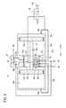
図1ないし図4及び図6において、参照符号10は、本発明の第1の実施形態に係る増圧装置を示す。本実施形態の増圧装置は、圧力流体(圧縮空気)の供給源である図示しないコンプレッサと、増圧された圧縮空気により作動する図示しないアクチュエータとの間に配設される。 In FIGS. 1 to 4 and 6,
この増圧装置10は、図3に示されるように、一対のシリンダチューブ(シリンダ)12a、12b及び一対のピストン14a、14bを含むシリンダ機構と、一対のシリンダチューブ12a、12bの間に設けられ、調整弁16及び切換弁18が組み込まれるセンターユニット20を有する。 As shown in FIG. 3, the
各シリンダチューブ12a、12bは筒状に形成され、その端部がエンドプレート22a、22bにより閉塞される。各ピストン14a、14bはシリンダチューブ12a、12bの内部に変位自在に配設され、各ピストン14a、14bの外周面には環状溝を介してピストンパッキン24が装着される。 Each of the
図4に示されるように、一対のピストン14a、14bはピストンロッド26により相互に一体的に連結される。センターユニット20は、その中央部に軸線方向(矢印AB方向)に沿って貫通したロッド孔28を有し、該ロッド孔28にはピストンロッド26が軸線方向に沿って変位自在に挿通されている。 As shown in FIG. 4, the pair of
図3に示されるように、各シリンダチューブ12a、12bの内部にはピストン14a、14bが挿通されるシリンダ室30a、30bが形成され、シリンダ室30a、30bと平行して流体通路32a、32bが形成されている。各流体通路32a、32bは、シリンダ室30a、30bから分離して形成され、エンドプレート22a、22bが装着されるシリンダチューブ12a、12bの端部側でシリンダ室30a、30bに連通している。 As shown in FIG. 3,
各シリンダ室30a、30bは、ピストン14a、14bとエンドプレート22a、22bとの間に設けられ、圧力流体が給排される駆動室34a、34bと、ピストン14a、14bとセンターユニット20との間に設けられ、圧力流体を増圧する増圧室36a、36bとに区画される。各流体通路32a、32bは、それぞれ第1通路38a、38bを介してシリンダ室30a、30bの駆動室34a、34bと連通している。 Each of the
シリンダチューブ12a、12bの外側において、一方のエンドプレート22aから他方のエンドプレート22bに向けて複数のタイロッド40が挿通され、該タイロッド40の他方のエンドプレート22bから突出する端部にナット42が締め付けられる。これにより、センターユニット20は、一方のシリンダチューブ12aと他方のシリンダチューブ12bとの間に保持される。センターユニット20は、センターボデイ44とセンターボデイ44の軸線方向(矢印AB方向)両端に取り付けられる一対のサイドプレート46を含む。 A plurality of
センターボデイ44は、コンプレッサからの圧力流体が供給される供給ポート45と、増圧された圧力流体がアクチュエータに向けて出力される出力ポート47と、圧力流体が排出される排出ポート48を有する。供給ポート45は、一対の増圧室36a、36bに連通するセンターボデイ44内の導入通路50に接続される(図4参照)とともに、切換弁18を介して一対の流体通路32a、32bのいずれか一方に連通するセンターボデイ44内の供給通路52に接続されている(図3参照)。供給通路52には、出力ポート47の圧力がフィードバックされる調整弁16が設けられており、作業者がセンターボデイ44の上部に設けられたハンドル54を回転させることにより、圧力流体の流量を調整することができる。 The
図4に示されるように、導入通路50と各増圧室36a、36bとの間には、導入通路50から増圧室36a、36bに向かう流体の流れを許容し、増圧室36a、36bから導入通路50に向かう流体の流れを阻止する第1チェック弁56a、56bが設けられる。出力ポート47は、一対の増圧室36a、36bに連通するセンターボデイ44内の導出通路58に接続される。該導出通路58と各増圧室36a、36bとの間には、増圧室36a、36bから導出通路58に向かう流体の流れを許容し、導出通路58から増圧室36a、36bに向かう流体の流れを阻止する第2チェック弁60a、60bが設けられる。第1チェック弁56a、56b及び第2チェック弁60a、60bは、サイドプレート46によってセンターボデイ44に組み込まれる。 As shown in FIG. 4, between the
図5に示されるように、切換弁18は、サイドプレート46によってセンターボデイ44に組み込まれるバルブボデイアセンブリ62と、バルブボデイアセンブリ62内で摺動するスプール64と、各増圧室36a、36b内に突出する一対のプッシュロッド66a、66bを備える。バルブボデイアセンブリ62は、筒状のスリーブ68とスリーブ68の両側に配置される一対のサイドバルブボデイ70を含む。 As shown in FIG. 5, the
スリーブ68には、入口ポート72が軸線方向(矢印AB方向)中央に設けられるとともに、入口ポート72から軸線方向に距離を隔てて入口ポート72の両側に出口ポート76a、76bが設けられる。入口ポート72は供給通路52に接続され、各出口ポート76a、76bは、それぞれ第2通路74a、74bを介して流体通路32a、32bに接続される。また、サイドバルブボデイ70内には、排出ポート48に接続される一対の排気通路78が設けられる。センターボデイ44とバルブボデイアセンブリ62との間には、これら入口ポート72、出口ポート76a、76b、排気通路78の相互間を気密に保つシール部材80が設けられている。 In the
スプール64は筒状に形成され、スプール64の外周には、スリーブ68の内周面に摺接する第1ランド部82及び第2ランド部84が設けられている。スプール64がバルブボデイアセンブリ62内で右方(矢印A方向)に摺動すると、第1ランド部82が左方の出口ポート76bと入口ポート72との間に位置するとともに、第2ランド部84が右方の出口ポート76aと右方の排気通路78との間に位置する。以下、この状態をスプール64ないし切換弁18が「第1位置」にあるという(図6参照)。スプール64がバルブボデイアセンブリ62内で左方(矢印B方向)に摺動すると、第1ランド部82が左方の排気通路78と左方の出口ポート76bとの間に位置するとともに、第2ランド部84が入口ポート72と右方の出口ポート76aとの間に位置する。以下、この状態をスプール64ないし切換弁18が「第2位置」にあるという。これにより、一対の出口ポート76a、76bに対して供給通路52と排気通路78とを切り換えることが可能となっている。 The
各プッシュロッド66a、66bは、サイドバルブボデイ70の中央に軸線方向(矢印AB方向)に沿って貫通した挿通孔内に移動自在に挿通され、プッシュロッド66a、66bとサイドバルブボデイ70との間にはシール部材86が設けられている。各プッシュロッド66a、66bは、増圧室36a、36b側に突出する端部においてピストン14a、14bと当接可能である。 Each of the
スプール64の内周面には、軸線方向の所定長さにわたって内方に突出する小径部88が設けられることで、一対の段部90が形成されている。一対のプッシュロッド66a、66bの相対向する端部はスプール64内に挿入され、各プッシュロッド66a、66bは、該端部に形成された第1フランジ部92においてスプール64の段部90と係合可能である。各プッシュロッド66a、66bには軸線方向中央寄りの箇所に第2フランジ部94が形成されており、第2フランジ部94がサイドバルブボデイ70に当接することで、プッシュロッド66a、66bの増圧室36a、36b側への移動が規制されている。一対のプッシュロッド66a、66bの相対向する端部間には戻しばね96が設けられる。 A pair of
図3に示されるように、センターボデイ44に弁体100とリセットボタン102を含むリセット弁98が取り付けられている。リセット弁98は、供給通路52に接続した第3通路106と一方の流体通路32aに接続した第2通路74aとの間で連通と遮断を切り換え可能な常閉弁として構成されている。弁体100がスプリング104の付勢力を受けることで、通常、リセット弁98は遮断位置に切り換えられている。一方、作業者がリセットボタン102を押すと、弁体100がリセットボタン102に押されスプリング104の付勢力に抗して移動する。これにより、第3通路106が第2通路74aに連通し、コンプレッサからの圧力流体が一方の駆動室34aに直接導入される。 As shown in FIG. 3, a
本発明の第1の実施形態に係る増圧装置10は、基本的には以上のように構成されるものであり、次にその動作並びに作用効果について説明する。なお、図6に示されるように、切換弁18が第1位置にあり、かつ、一方のピストン14aが一方のエンドプレート22a側(矢印A方向)に変位した状態を初期位置とする。 The
この初期位置では、スプール64の第2ランド部84が右方の出口ポート76aと右方の排気通路78との間に位置しており、右方の出口ポート76aは入口ポート72に連通している。すなわち、一方の流体通路32aは第2通路74aを介して供給通路52に繋がっている。また、スプール64の第1ランド部82が左方の出口ポート76bと入口ポート72との間に位置しており、左方の出口ポート76bは左方の排気通路78に連通している。すなわち、他方の流体通路32bは第2通路74bを介して排気通路78に繋がっている。 In this initial position, the
この初期位置において、図示しないコンプレッサから供給ポート45へと圧力流体を供給することにより、該圧力流体が導入通路50に流入し、第1チェック弁56a、56bを介して増圧室36a、36bに導入される。 In this initial position, by supplying a pressure fluid from a compressor (not shown) to the
供給ポート45から供給された圧力流体の一部は、調整弁16によって流量が調整された後、供給通路52を通って切換弁18へと流通する。そして、第1位置にある切換弁18を通じて、圧力流体が一方の流体通路32aに供給され、さらに一方の駆動室34aへと供給される。 A part of the pressure fluid supplied from the
この駆動室34aに導入された圧力流体によってピストン14aがセンターユニット20側(矢印B方向)へと押圧され、該ピストン14aによって増圧室36aの圧力流体が増圧される。この増圧した圧力流体が、第2チェック弁60aを通って導出通路58から出力ポート47へと導かれて出力される。 The
一方、ピストン14aと一体的に移動するピストン14bの摺動により容積が小さくなる他方の駆動室34b内の圧力流体は、流体通路32bと第1位置にある切換弁18を通じて排気通路78に至り、排出ポート48から排出される。 On the other hand, the pressure fluid in the
そして、ピストン14aがセンターユニット20側(矢印B方向)に変位した終端位置において、ピストン14aが切換弁18のプッシュロッド66aに当接してこれを押圧する。これにより、プッシュロッド66aがその第1フランジ部92においてスプール64に係合し、スプール64が第2位置へと移動する。すなわち、切換弁18が第2位置に切り換わる。 Then, at the terminal position where the
今度は、供給通路52に供給された圧力流体が第2位置にある切換弁18を通じて他方の流体通路32b及び他方の駆動室34bへと供給され、他方のピストン14bがセンターユニット20側(矢印A方向)に向かって変位する。これにより、増圧室36bの圧力流体が増圧され、この増圧した圧力流体が第2チェック弁60bを通って出力ポート47から出力される。ピストン14bがセンターユニット20側(矢印A方向)に変位した終端位置において、ピストン14bがプッシュロッド66bを押圧すると、再び切換弁18が第1位置に切り換わり、駆動室34aに圧力流体が供給される。以下、同様にピストン14a及びピストン14bが一体となって往復運動を繰り返し、増圧された圧力流体が出力ポート47から連続的に出力される。 This time, the pressure fluid supplied to the
ここで、供給される圧力流体の圧力が低かったり、増圧室36a、36bと駆動室34a、34bの圧力差が小さかったり、排出ポート48に背圧がかかったりすることに起因して、ピストン14a、14bの推力が不十分となる場合がある。また、ピストン14a、14bまたは切換弁18の摺動抵抗が大きくなる場合がある。 Here, due to the low pressure of the supplied pressure fluid, the small pressure difference between the
このような場合に、スプール64が第1位置と第2位置とのちょうど中間の位置で停止したままの状態となることがある。このとき、第1ランド部82は左方の出口ポート76bと概ね重なる位置にあって、入口ポート72と左方の出口ポート76bとの間、及び左方の出口ポート76bと左方の排気通路78との間は、いずれも不完全な遮断状態となっていると考えられる。同様に、第2ランド部84は右方の出口ポート76aと概ね重なる位置にあって、入口ポート72と右方の出口ポート76aとの間、及び右方の出口ポート76aと右方の排気通路78との間は、いずれも不完全な遮断状態となっていると考えられる。 In such a case, the
上記の状態となったとき、作業者がリセットボタン102を押すと、コンプレッサからの圧力流体が一方の駆動室34aに直接導入される。これにより、一方のピストン14aがセンターユニット20側へと押圧され、増圧装置10が再起動する。 In this state, when the operator presses the
本実施形態に係る増圧装置10によれば、手動により操作可能なリセット弁98が供給ポート45と一方の駆動室34aとを接続する流路に配設されているので、供給される流体圧力の低下等により切換弁18が中立位置に停止しても容易に再起動することができる。 According to the
次に、本発明の第2の実施形態に係る増圧装置110を図7に示す。増圧装置110は、リセット弁112に係る構成が第1の実施形態におけるリセット弁98と異なる。なお、第1の実施形態に係る増圧装置10と同一の構成要素には同一の参照符号を付して、その詳細な説明を省略する。 Next, FIG. 7 shows a
リセット弁112は、供給通路52と一方の流体通路32aとの間で連通と遮断を切り換え可能な常閉弁として構成されるとともに、一方の流体通路32a内の流体圧力がパイロット圧として作用している。すなわち、リセット弁112は、一方の流体通路32a内の流体圧力が所定値より大きければ、連通位置に切り換わるように動作する。 The
また、作業者がリセットボタン102を押すことにより、供給通路52と一方の流体通路32aを連通せしめ、コンプレッサからの圧力流体を一方の駆動室34aに直接導入することも可能である。 Further, when the operator presses the
本実施形態に係る増圧装置110によれば、リセット弁112は、一方の駆動室34aの流体圧力をパイロット圧として連通位置に切り換わるように動作するので、切換弁18が中立位置に停止しても、一方の駆動室34aの流体圧力が所定値より大きいときは、切換弁18が作動して増圧装置110が再起動する。 According to the
本発明に係る増圧装置は、上述の実施形態に限らず、本発明の要旨を逸脱することのない範囲で、種々の構成を採り得ることはもちろんである。 The pressure intensifier according to the present invention is not limited to the above-described embodiment, but may adopt various configurations without departing from the gist of the present invention.
10、110…増圧装置
12a、12b…シリンダチューブ(シリンダ)
14a、14b…ピストン 18…切換弁
20…センターユニット 26…ピストンロッド
34a、34b…駆動室 36a、36b…増圧室
45…供給ポート 47…出力ポート
48…排出ポート 64…スプール
66a、66b…プッシュロッド 98、112…リセット弁10, 110 ...
14a,
Claims (5)
Translated fromJapanese前記シリンダは前記ピストンによって画成される駆動室と増圧室とを有し、前記ピストンと当接することによって切り換えられ、前記一対の駆動室の一方または他方を前記供給ポートに連通するとともに前記一対の駆動室の他方または一方を前記排出ポートに連通する切換弁と、前記供給ポートと前記一対の駆動室の一方とを接続する流路に配設されるリセット弁を備える増圧装置。A center unit, a pair of cylinders provided with the center unit interposed therebetween, a piston disposed inside each of the pair of cylinders, a piston rod connecting the pair of pistons, A pressure booster comprising a port, an output port from which the increased pressure fluid is output, and a discharge port from which the pressure fluid is discharged,
The cylinder has a drive chamber and a pressure-intensifying chamber defined by the piston, and is switched by abutting on the piston, so that one or the other of the pair of drive chambers communicates with the supply port while And a reset valve disposed in a flow path connecting the supply port and one of the pair of drive chambers.
前記切換弁は、前記センターユニットに組み込まれ、前記ピストンと当接可能な一対のプッシュロッドと前記一対のプッシュロッドにより摺動せしめられるスプールを備える
ことを特徴とする増圧装置。The pressure intensifier according to claim 1,
The pressure increasing device, wherein the switching valve includes a pair of push rods that are incorporated in the center unit and that can contact the piston, and a spool that is slid by the pair of push rods.
前記リセット弁は、前記供給ポートと前記一対の駆動室の一方との間で連通と遮断を切り換え可能であり、手動により連通位置に切り換えることができる常閉弁として構成されている
ことを特徴とする増圧装置。The pressure intensifier according to claim 1,
The reset valve is configured as a normally-closed valve that can switch between communication and cutoff between the supply port and one of the pair of drive chambers, and that can be manually switched to a communication position. Pressure intensifier.
前記リセット弁は、前記一方の駆動室の流体圧力をパイロット圧として連通位置に切り換わるように動作する
ことを特徴とする増圧装置。The pressure intensifier according to claim 3,
The pressure increasing device, wherein the reset valve operates so as to switch to the communication position using the fluid pressure of the one drive chamber as a pilot pressure.
前記リセット弁は、前記センターユニットに組み込まれる
ことを特徴とする増圧装置。The pressure intensifier according to claim 3,
The pressure increasing device, wherein the reset valve is incorporated in the center unit.
Priority Applications (10)
| Application Number | Priority Date | Filing Date | Title |
|---|---|---|---|
| JP2017076416AJP6665985B2 (en) | 2017-04-07 | 2017-04-07 | Pressure booster |
| KR1020197032978AKR102209368B1 (en) | 2017-04-07 | 2018-02-26 | Pressure intensifier |
| BR112019020814ABR112019020814A2 (en) | 2017-04-07 | 2018-02-26 | pressure booster |
| PCT/JP2018/006850WO2018186048A1 (en) | 2017-04-07 | 2018-02-26 | Pressure booster |
| RU2019135611ARU2736237C9 (en) | 2017-04-07 | 2018-02-26 | Pressure booster |
| MX2019011829AMX2019011829A (en) | 2017-04-07 | 2018-02-26 | Pressure booster. |
| US16/603,059US10876550B2 (en) | 2017-04-07 | 2018-02-26 | Pressure booster |
| CN201880022961.9ACN110520633B (en) | 2017-04-07 | 2018-02-26 | supercharger |
| DE112018001885.7TDE112018001885T5 (en) | 2017-04-07 | 2018-02-26 | booster |
| TW107108446ATWI681132B (en) | 2017-04-07 | 2018-03-13 | Pressure booster |
Applications Claiming Priority (1)
| Application Number | Priority Date | Filing Date | Title |
|---|---|---|---|
| JP2017076416AJP6665985B2 (en) | 2017-04-07 | 2017-04-07 | Pressure booster |
Publications (2)
| Publication Number | Publication Date |
|---|---|
| JP2018179074A JP2018179074A (en) | 2018-11-15 |
| JP6665985B2true JP6665985B2 (en) | 2020-03-13 |
Family
ID=61622648
Family Applications (1)
| Application Number | Title | Priority Date | Filing Date |
|---|---|---|---|
| JP2017076416AActiveJP6665985B2 (en) | 2017-04-07 | 2017-04-07 | Pressure booster |
Country Status (10)
| Country | Link |
|---|---|
| US (1) | US10876550B2 (en) |
| JP (1) | JP6665985B2 (en) |
| KR (1) | KR102209368B1 (en) |
| CN (1) | CN110520633B (en) |
| BR (1) | BR112019020814A2 (en) |
| DE (1) | DE112018001885T5 (en) |
| MX (1) | MX2019011829A (en) |
| RU (1) | RU2736237C9 (en) |
| TW (1) | TWI681132B (en) |
| WO (1) | WO2018186048A1 (en) |
Families Citing this family (8)
| Publication number | Priority date | Publication date | Assignee | Title |
|---|---|---|---|---|
| EP3950221A4 (en)* | 2019-03-26 | 2022-12-14 | Canon Denshi Kabushiki Kaisha | Processing apparatus |
| JP7063434B2 (en)* | 2019-05-17 | 2022-05-09 | Smc株式会社 | Pressure booster |
| KR102078514B1 (en)* | 2019-12-09 | 2020-02-17 | 정종범 | oral irrigator directly connected to faucet and operating without electric power supply |
| JP7484312B2 (en)* | 2020-03-27 | 2024-05-16 | Smc株式会社 | Booster output stabilization device |
| CN111536089A (en)* | 2020-06-04 | 2020-08-14 | 新立行科技浙江有限公司 | A Durable Booster Cylinder Structure Based on Skeleton Structure |
| CN114060329A (en)* | 2020-08-04 | 2022-02-18 | 费斯托(中国)自动化制造有限公司 | Pneumatic booster |
| IT202100014633A1 (en)* | 2021-06-04 | 2022-12-04 | Camozzi Automation S P A | PRESSURE MULTIPLIER |
| CN115263861A (en)* | 2022-06-27 | 2022-11-01 | 费斯托(中国)自动化制造有限公司 | Counting device for supercharger and supercharger |
Family Cites Families (29)
| Publication number | Priority date | Publication date | Assignee | Title |
|---|---|---|---|---|
| DE325269C (en)* | 1919-08-19 | 1920-09-11 | Wilhelm Vaupel | Shake slide motor |
| US2925782A (en)* | 1953-02-17 | 1960-02-23 | Sperry Gyroscope Co Ltd | Liquid pump |
| US3354912A (en)* | 1965-01-11 | 1967-11-28 | Carroll G Gordon | Sectional hydraulic valve structure |
| US4634350A (en)* | 1981-11-12 | 1987-01-06 | The Coca-Cola Company | Double acting diaphragm pump and reversing mechanism therefor |
| DE3428136A1 (en)* | 1984-07-31 | 1986-02-13 | Alfred Teves Gmbh, 6000 Frankfurt | BRAKE PRESSURE SENSOR FOR A HYDRAULIC MOTOR VEHICLE BRAKE SYSTEM |
| GB2162591B (en)* | 1984-08-02 | 1988-05-25 | Shoketsu Kinzoku Kogyo Kk | Fluid pressure booster |
| US4827831A (en)* | 1987-12-30 | 1989-05-09 | Product Research And Development | Reciprocating device and switching mechanism therefor |
| US5554011A (en)* | 1994-10-27 | 1996-09-10 | Symbiosis Corporation | Medical fluid pump powered by a constant source of vacuum |
| JPH08270601A (en)* | 1995-03-29 | 1996-10-15 | Nisshinbo Ind Inc | Air tank unit and work vehicle with air tank |
| DE19516977C2 (en)* | 1995-05-09 | 1997-03-27 | Szabo Zsolt | Pneumatic drive device |
| JPH10267002A (en)* | 1997-03-25 | 1998-10-06 | Smc Corp | Pressure booster |
| SE9704160L (en)* | 1997-11-13 | 1999-05-14 | Svante Bahrton | valve device |
| JP3515070B2 (en)* | 2000-12-18 | 2004-04-05 | 株式会社ヤマダコーポレーション | Pump restarter |
| JP3595985B2 (en)* | 2001-01-22 | 2004-12-02 | 株式会社フクハラ | Method and apparatus for producing high-pressure nitrogen gas |
| JP3416656B2 (en)* | 2001-01-23 | 2003-06-16 | 株式会社ワイ・テイ・エス | Pump switching valve restart device |
| RU21303U1 (en)* | 2001-06-29 | 2002-01-10 | Акционерное общество "АвтоВАЗ" | PRESSURE RISING STATION |
| US7175395B1 (en)* | 2002-06-04 | 2007-02-13 | Forest Daniel L | Pressure enhancer value system |
| RU31154U1 (en)* | 2003-03-31 | 2003-07-20 | Открытое акционерное общество "АВТОВАЗ" | Pressure boosting station |
| RU2258840C1 (en)* | 2003-12-16 | 2005-08-20 | Республиканское унитарное предприятие "Минский тракторный завод" | Pneumohydraulic booster |
| US7980270B2 (en)* | 2005-05-12 | 2011-07-19 | Shurflo, Llc | Spool valve apparatus and method |
| JP4301310B2 (en)* | 2007-03-12 | 2009-07-22 | Smc株式会社 | Booster |
| US7603854B2 (en)* | 2007-04-10 | 2009-10-20 | Illinois Tool Works Inc. | Pneumatically self-regulating valve |
| US9127657B2 (en)* | 2010-03-29 | 2015-09-08 | Wilden Pump And Engineering Llc | Air-driven pump system |
| TWM446237U (en)* | 2012-07-27 | 2013-02-01 | Kinyao Entpr Co Ltd | Structure of air pressure boosting cylinder |
| KR20140094229A (en)* | 2013-01-21 | 2014-07-30 | (주) 티피씨 메카트로닉스 | Pressure booster circuit |
| TWM514372U (en)* | 2015-07-13 | 2015-12-21 | bo-rong Chen | Pressurization system for machining center cleaning deice |
| CN205225899U (en)* | 2015-11-29 | 2016-05-11 | 深圳市米高科技有限公司 | Two -way hydraulic pressure booster device |
| TWM524398U (en)* | 2015-12-04 | 2016-06-21 | Ding-Wen Lai | Pneumatic type hydraulic boosting device |
| CN106402055A (en)* | 2016-08-26 | 2017-02-15 | 广西柳州银海铝业股份有限公司 | Hydraulic system of coil stripping car |
- 2017
- 2017-04-07JPJP2017076416Apatent/JP6665985B2/enactiveActive
- 2018
- 2018-02-26KRKR1020197032978Apatent/KR102209368B1/ennot_activeExpired - Fee Related
- 2018-02-26MXMX2019011829Apatent/MX2019011829A/enunknown
- 2018-02-26USUS16/603,059patent/US10876550B2/ennot_activeExpired - Fee Related
- 2018-02-26WOPCT/JP2018/006850patent/WO2018186048A1/ennot_activeCeased
- 2018-02-26DEDE112018001885.7Tpatent/DE112018001885T5/ennot_activeWithdrawn
- 2018-02-26CNCN201880022961.9Apatent/CN110520633B/ennot_activeExpired - Fee Related
- 2018-02-26BRBR112019020814Apatent/BR112019020814A2/ennot_activeIP Right Cessation
- 2018-02-26RURU2019135611Apatent/RU2736237C9/enactive
- 2018-03-13TWTW107108446Apatent/TWI681132B/ennot_activeIP Right Cessation
Also Published As
| Publication number | Publication date |
|---|---|
| CN110520633A (en) | 2019-11-29 |
| KR102209368B1 (en) | 2021-01-29 |
| TWI681132B (en) | 2020-01-01 |
| BR112019020814A2 (en) | 2020-04-28 |
| CN110520633B (en) | 2021-07-16 |
| KR20190133257A (en) | 2019-12-02 |
| JP2018179074A (en) | 2018-11-15 |
| WO2018186048A1 (en) | 2018-10-11 |
| US20200072249A1 (en) | 2020-03-05 |
| US10876550B2 (en) | 2020-12-29 |
| RU2736237C1 (en) | 2020-11-12 |
| TW201839274A (en) | 2018-11-01 |
| RU2736237C9 (en) | 2021-05-31 |
| MX2019011829A (en) | 2019-11-07 |
| DE112018001885T5 (en) | 2019-12-19 |
Similar Documents
| Publication | Publication Date | Title |
|---|---|---|
| JP6665985B2 (en) | Pressure booster | |
| EP1048854A2 (en) | Servo-driving pilot-type solenoid valve | |
| JP6572872B2 (en) | Booster | |
| TWI680235B (en) | Pressure booster and cylinder device comprising same | |
| JP3542299B2 (en) | Pneumatic fluid control valve device | |
| KR20140094325A (en) | Bypass device for a main air ventilation of a pressure booster | |
| US7955058B1 (en) | Reciprocating piston to piston energy pump | |
| JPH10267002A (en) | Pressure booster | |
| JP2004340149A (en) | Diaphragm pump system | |
| CN116104725B (en) | Fluid flow direction switching valve and automatic control switching straight stroke reciprocating power device | |
| WO2016178587A1 (en) | A pneumatic or hydraulic mechanism | |
| KR20210120905A (en) | Pressure-booster output stabilizer | |
| JP7436426B2 (en) | Pressure booster | |
| JPH0244066Y2 (en) | ||
| JP3792000B2 (en) | Nitrogen gas booster | |
| JP2512551Y2 (en) | Pressure converter | |
| JPH0527681Y2 (en) | ||
| KR20150016677A (en) | Automatic pressure regulating control device for reciprocatable double acting booster | |
| JPH0346244Y2 (en) | ||
| KR101366438B1 (en) | Control valve for reciprocatable double acting fluidic device | |
| KR101497976B1 (en) | Automatic reciprocating motion control device for reciprocatable double acting booster | |
| JP3023872B2 (en) | Mechanical shift device and pneumatic auxiliary pilot valve for diaphragm pump | |
| JP3649358B2 (en) | Solenoid switching valve | |
| JPH049445Y2 (en) | ||
| JP2014025354A (en) | Air drive type diaphragm pump |
Legal Events
| Date | Code | Title | Description |
|---|---|---|---|
| A621 | Written request for application examination | Free format text:JAPANESE INTERMEDIATE CODE: A621 Effective date:20181219 | |
| TRDD | Decision of grant or rejection written | ||
| A01 | Written decision to grant a patent or to grant a registration (utility model) | Free format text:JAPANESE INTERMEDIATE CODE: A01 Effective date:20200107 | |
| A61 | First payment of annual fees (during grant procedure) | Free format text:JAPANESE INTERMEDIATE CODE: A61 Effective date:20200205 | |
| R150 | Certificate of patent or registration of utility model | Ref document number:6665985 Country of ref document:JP Free format text:JAPANESE INTERMEDIATE CODE: R150 | |
| R250 | Receipt of annual fees | Free format text:JAPANESE INTERMEDIATE CODE: R250 | |
| R250 | Receipt of annual fees | Free format text:JAPANESE INTERMEDIATE CODE: R250 | |
| R250 | Receipt of annual fees | Free format text:JAPANESE INTERMEDIATE CODE: R250 |