JP6663449B2 - Flight training support system - Google Patents
Flight training support systemDownload PDFInfo
- Publication number
- JP6663449B2 JP6663449B2JP2018045710AJP2018045710AJP6663449B2JP 6663449 B2JP6663449 B2JP 6663449B2JP 2018045710 AJP2018045710 AJP 2018045710AJP 2018045710 AJP2018045710 AJP 2018045710AJP 6663449 B2JP6663449 B2JP 6663449B2
- Authority
- JP
- Japan
- Prior art keywords
- aircraft
- flight
- virtual
- simulated
- support system
- Prior art date
- Legal status (The legal status is an assumption and is not a legal conclusion. Google has not performed a legal analysis and makes no representation as to the accuracy of the status listed.)
- Active
Links
- 238000012549trainingMethods0.000titleclaimsdescription48
- 230000015572biosynthetic processEffects0.000claimsdescription16
- RZVHIXYEVGDQDX-UHFFFAOYSA-N9,10-anthraquinoneChemical groupC1=CC=C2C(=O)C3=CC=CC=C3C(=O)C2=C1RZVHIXYEVGDQDX-UHFFFAOYSA-N0.000claimsdescription15
- 238000012360testing methodMethods0.000claimsdescription3
- 238000012545processingMethods0.000description13
- 238000009795derivationMethods0.000description10
- 238000010586diagramMethods0.000description9
- 238000000034methodMethods0.000description5
- 230000005540biological transmissionEffects0.000description4
- 230000006870functionEffects0.000description4
- 230000007246mechanismEffects0.000description4
- 230000008569processEffects0.000description3
- 238000002485combustion reactionMethods0.000description2
- 230000000694effectsEffects0.000description2
- 230000008901benefitEffects0.000description1
- 238000007796conventional methodMethods0.000description1
- 239000000463materialSubstances0.000description1
- 238000005259measurementMethods0.000description1
- 238000012986modificationMethods0.000description1
- 230000004048modificationEffects0.000description1
- 239000004065semiconductorSubstances0.000description1
Images


Classifications
- G—PHYSICS
- G09—EDUCATION; CRYPTOGRAPHY; DISPLAY; ADVERTISING; SEALS
- G09B—EDUCATIONAL OR DEMONSTRATION APPLIANCES; APPLIANCES FOR TEACHING, OR COMMUNICATING WITH, THE BLIND, DEAF OR MUTE; MODELS; PLANETARIA; GLOBES; MAPS; DIAGRAMS
- G09B9/00—Simulators for teaching or training purposes
- G09B9/02—Simulators for teaching or training purposes for teaching control of vehicles or other craft
- G09B9/08—Simulators for teaching or training purposes for teaching control of vehicles or other craft for teaching control of aircraft, e.g. Link trainer
- G09B9/30—Simulation of view from aircraft
- G09B9/307—Simulation of view from aircraft by helmet-mounted projector or display
- G—PHYSICS
- G09—EDUCATION; CRYPTOGRAPHY; DISPLAY; ADVERTISING; SEALS
- G09B—EDUCATIONAL OR DEMONSTRATION APPLIANCES; APPLIANCES FOR TEACHING, OR COMMUNICATING WITH, THE BLIND, DEAF OR MUTE; MODELS; PLANETARIA; GLOBES; MAPS; DIAGRAMS
- G09B9/00—Simulators for teaching or training purposes
- G09B9/02—Simulators for teaching or training purposes for teaching control of vehicles or other craft
- G09B9/08—Simulators for teaching or training purposes for teaching control of vehicles or other craft for teaching control of aircraft, e.g. Link trainer
- G09B9/30—Simulation of view from aircraft
- G09B9/301—Simulation of view from aircraft by computer-processed or -generated image
Landscapes
- Engineering & Computer Science (AREA)
- Theoretical Computer Science (AREA)
- Aviation & Aerospace Engineering (AREA)
- Business, Economics & Management (AREA)
- Physics & Mathematics (AREA)
- Educational Administration (AREA)
- Educational Technology (AREA)
- General Physics & Mathematics (AREA)
- Computer Hardware Design (AREA)
- Control Of Position, Course, Altitude, Or Attitude Of Moving Bodies (AREA)
- Traffic Control Systems (AREA)
Description
Translated fromJapanese本発明は、飛行訓練を支援する飛行訓練支援システムに関する。 The present invention relates to a flight training support system that supports flight training.
航空機の飛行態様としては、単独飛行と編隊飛行とがある。編隊飛行の飛行訓練では、自機(自分が操縦する航空機)の飛行方位や速度のみならず、僚機(自機と編隊を組む味方の航空機)と自機とが適切な位置関係となるように制御しなければならない。 The flight modes of the aircraft include a solo flight and a formation flight. In flight training for formation flight, not only the flight direction and speed of your aircraft (the aircraft you control), but also to make sure that your own aircraft (friend aircraft that forms a formation with your aircraft) and your aircraft have an appropriate positional relationship. You have to control.
そこで、航空機のヘッドアップディスプレイに仮想教官機(VIA)のシンボルを重畳し、僚機との編隊飛行を仮想現実として表す技術が知られている(例えば、特許文献1)。 Therefore, there is known a technique in which a virtual instructor (VIA) symbol is superimposed on a head-up display of an aircraft to represent a formation flight with a consort aircraft as virtual reality (for example, Patent Document 1).
パイロットを養成する際、実機を用いた飛行訓練は必須であるが、編隊飛行の訓練を実施しようとすると、その航空機の数だけコストを要することとなり、また、訓練でありながら自機が僚機と接触する危険性が生じてしまう。 When training a pilot, flight training using actual aircraft is essential, but if you try to conduct formation flight training, it will cost as much as the number of aircraft, and even while training, your aircraft will be There is a risk of contact.
ここで、特許文献1のように、仮想教官機を用いることも考えられるが、単に仮想教官機を表示するだけでは、仮想教官機が前方を飛行することによるウェーキの影響等が模擬されず、十分な飛行訓練とは言えなかった。 Here, as in Patent Document 1, it is conceivable to use a virtual instructor, but simply displaying the virtual instructor does not simulate the influence of a wake caused by the virtual instructor flying forward, It was not enough flight training.
そこで、本発明は、実機における編隊飛行の飛行訓練を適切に実行することが可能な飛行訓練支援システムを提供することを目的としている。 Therefore, an object of the present invention is to provide a flight training support system capable of appropriately executing flight training for formation flight on a real machine.
上記課題を解決するために、パイロットが自機を操縦して飛行している状態において実行される本発明の飛行訓練支援システムは、予め設定された数の仮想僚機が自機とともに編隊飛行しているとした場合における、仮想僚機の模擬飛行状態を所定時間経過毎に生成する飛行状態生成部と、仮想僚機の模擬飛行状態と自機の実飛行状態とに基づいて、自機に対する仮想僚機の相対位置を所定時間経過毎に導出する相対位置導出部と、透過型ディスプレイにおける仮想僚機の相対位置に仮想僚機を示す指標を表示する表示制御部と、仮想僚機の模擬飛行状態と仮想僚機の相対位置とに基づいて、仮想僚機の飛行により自機が受ける模擬変動量を導出する変動量導出部と、模擬変動量を受けた状態となるように自機を実変動させる飛行制御部と、を備える。
飛行制御部は、自機の高度が所定高度以上の場合、または、自機が所定の試験空域に位置している場合に、模擬変動量を受けた状態となるように自機を実変動させるとしてもよい。
変動量導出部は、仮想僚機の飛行により自機のロール回転方向に受ける模擬変動量を導出してもよい。In order to solve the above problems, the flight training support system of the present invention,which is executed in a state where thepilot is maneuvering the own aircraft and flying, has apreset number of virtual consorts flying in formation with the own aircraft. And a flight state generation unitthat generates a simulated flight stateof the virtual wingevery time a predetermined time elapses , and based on the simulated flight state of the virtual wing and the actual flight state of the own aircraft, A relative position deriving unitthat derives a relative positionevery time a predetermined time elapses, a display control unit that displays an index indicating the virtual wrestler at the relative position of the virtual wrestler on the transmissive display, a simulated flight state of the virtual wrestler and the relative position of the virtual wrestler A variation derivation unit that derives a simulated variation received by the own aircraft based on the position based on the position, and a flight control unit that actually varies the own aircraft so as to receive the simulated variation, Provided.
The flight control unit, when the altitude of the own aircraft is equal to or higher than a predetermined altitude, or when the own aircraft is located in a predetermined test airspace, actually changes the own aircraft so as to receive the simulated fluctuation amount. It may be.
The variation deriving unit may derive a simulated variation received in the roll rotation direction of the own aircraft due to the flight of the virtual consort aircraft.
本発明によれば、実機における編隊飛行の飛行訓練を適切に実行することが可能となる。 ADVANTAGE OF THE INVENTION According to this invention, it becomes possible to perform flight training of formation flight in an actual machine appropriately.
以下に添付図面を参照しながら、本発明の好適な実施形態について詳細に説明する。かかる実施形態に示す寸法、材料、その他具体的な数値等は、発明の理解を容易とするための例示にすぎず、特に断る場合を除き、本発明を限定するものではない。なお、本明細書および図面において、実質的に同一の機能、構成を有する要素については、同一の符号を付することにより重複説明を省略し、また本発明に直接関係のない要素は図示を省略する。 Hereinafter, a preferred embodiment of the present invention will be described in detail with reference to the accompanying drawings. The dimensions, materials, other specific numerical values, and the like shown in the embodiments are merely examples for facilitating the understanding of the invention, and do not limit the present invention unless otherwise specified. In the specification and the drawings, elements having substantially the same function and configuration will be denoted by the same reference numerals, and redundant description will be omitted. Elements not directly related to the present invention will be omitted. I do.
図1は、航空機の操縦室を示す概略図である。自機(航空機)1の操縦室10内の前方側には計器盤12が設けられている。計器盤12には、操縦に必要な各種の計器14が配置されている。計器14としては、例えば、自機1の機体の水平面での位置(例えば、緯度、経度)を表示する位置表示計、機体の高度を表示する高度表示計、機体の姿勢を表示する姿勢表示計、磁方位を表示する磁方位計、機体内の温度を表示する温度計、操舵量を表示する操舵量表示計、エンジンの出力を表示する出力計などがある。なお、計器盤12には、例示した計器14に限らず、パイロット2が自機1の操縦において必要な様々な計器14が配置される。 FIG. 1 is a schematic diagram showing a cockpit of an aircraft. An
また、操縦室10内の前方側、かつ、計器盤12の上方には、自機1の外界を視認可能な透過窓16が設けられている。透過窓16には、パイロット2の視野に直接情報を表示するヘッドアップディスプレイ(透過型ディスプレイ)18が一体的に設けられている。例えば、ヘッドアップディスプレイ18として、ハーフミラーを透過窓16にコーティングし、パイロット2の視線方向と垂直となる方向から情報を投影する。こうして、パイロット2は、自機1の外界に相当する実空間を視認しつつ、視線を維持したまま、同時に、ヘッドアップディスプレイ18を通じて情報を得ることができる。 In addition, a
また、計器盤12の近傍には、操縦装置20が設けられている。操縦装置20は、パイロット2の操作入力を受ける、例えば、操縦桿で構成される。パイロット2は、操縦装置20を通じて自機1を操作する。なお、操縦装置20は、操縦桿に限らず、例えば、計器盤12やその近傍に配置される各種のレバーやスイッチなどのパイロット2の操作を受け付ける装置であればよい。 In the vicinity of the
図2は、編隊飛行訓練を説明するための説明図である。パイロット2を養成する際、実機を用いた飛行訓練は必須であるが、編隊飛行の訓練を実施しようとすると、その航空機の数だけコストを要することとなり、また、訓練でありながら自機1が実際に飛行している僚機と接触する危険性が生じてしまう。ここで、例えば、実際には存在しない仮想的な僚機(以下、「仮想僚機3」という)を用い、ヘッドアップディスプレイ18に表示することも考えられるが、仮想僚機3が前方を飛行することによるウェーキの影響(干渉)等が模擬されないので、十分な飛行訓練とは言えなかった。そこで、本実施形態では、図2のように、自機1に対して、仮想僚機3の飛行を模擬しつつ、仮想僚機3が仮に実際に飛行していた場合に仮想僚機3から自機1が受ける影響も考慮して、実機における編隊飛行の飛行訓練を適切に実行することを目的とする。 FIG. 2 is an explanatory diagram for explaining formation flight training. When training the
以下、このような目的を実現するための飛行訓練支援システム100の構成について詳述する。ここでは、本実施形態の目的である飛行訓練支援に必要な構成を説明し、本実施形態に関係のない構成については説明を省略する。 Hereinafter, the configuration of the flight
(飛行訓練支援システム100)
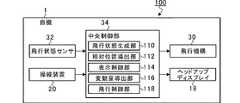
図3は、自機1の制御系を説明するための機能ブロック図である。自機1の飛行機構30は、翼が機体に固定されている固定翼と、推進力を得る内燃機関(例えば、ジェットエンジンやレシプロエンジン)とで構成され、推進力により翼周りに揚力を生じさせることで、機体が大気中に浮上した状態を維持する。ただし、揚力を生じさせる機構はかかる場合に限らず、回転可能に設けられた回転翼(ローター)により揚力を得たり、推進力を得ることも可能である。(Flight training support system 100)
FIG. 3 is a functional block diagram for explaining a control system of the own device 1. The
また、飛行機構30では、昇降舵や補助翼(エルロン)を通じてバンク角(ロール角)、機首角(ピッチ角)、内燃機関の出力等を調整することで、飛行方位(ヨー角)、高度、飛行速度を制御することも可能である。パイロット2は、操縦装置20を通じて飛行機構30を動作させ、自機1を操縦する。 Further, the
飛行状態センサ32は、自機1に設けられた航法センサ等の様々なセンサを通じて、飛行位置(経度、緯度、高度を含む)、機体速度、機体姿勢、機体が受ける風力、風向き、天候、機体周囲の気圧、温度、湿度等の現在の飛行状態を検出する。 The
中央制御部34は、中央処理装置(CPU)、プログラム等が格納されたROM、ワークエリアとしてのRAM等を含む半導体集積回路で構成され、自機1全体を管理および制御する。また、中央制御部34は、ROMやRAMと協働して、飛行訓練支援システム100として機能する、飛行状態生成部110、相対位置導出部112、表示制御部114、変動量導出部116、飛行制御部118としても動作する。以下、飛行訓練支援システム100による飛行訓練支援処理について、当該中央制御部34の各機能部の動作も踏まえて詳述する。 The
(飛行訓練支援処理)
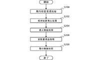
図4は、飛行訓練支援処理の流れを示すフローチャートである。ここでは、所定時間経過毎の割込信号に応じて当該飛行訓練支援処理が実行される。飛行訓練支援処理では、飛行状態生成部110が仮想僚機3の模擬飛行状態を生成し(S200)、相対位置導出部112が、自機1に対する仮想僚機3の相対位置を導出し(S202)、表示制御部114が、仮想僚機3の相対位置を実空間に重畳して表示し(S204)、変動量導出部116が、仮想僚機3の飛行によって自機1が受ける模擬変動量を導出し(S206)、飛行制御部118が、模擬変動量を受けた状態となるように自機1を実際に変動(実変動)させる(S208)。(Flight training support processing)
FIG. 4 is a flowchart illustrating the flow of the flight training support process. Here, the flight training support processing is executed according to an interrupt signal every time a predetermined time elapses. In the flight training support processing, the flight state generation unit 110 generates a simulated flight state of the virtual wingman 3 (S200), and the relative
(飛行状態生成処理S200)
飛行状態生成部110は、操作入力を通じて予め設定された数の仮想僚機3を対象とし、仮想僚機3それぞれに予め設定された飛行経路、飛行速度、飛行姿勢等に基づき、仮想僚機3の飛行を模擬(シミュレーション)する。なお、仮想僚機3の飛行の模擬については、従来の様々な技術を採用できるので、ここでは、その詳細な説明を省略する。(Flight state generation processing S200)
The flight state generation unit 110 targets a predetermined number of the
そして、飛行状態生成部110は、自機1が実際に飛行している間、仮想僚機3が仮に自機1と共に実際に編隊飛行していた場合の同時点における仮想僚機3の飛行状態を導出する。以下では、自機1が実際に飛行(実飛行)している飛行状態を「実飛行状態」というのに対し、仮想僚機3の模擬された飛行状態を「模擬飛行状態」という。 Then, the flight state generation unit 110 derives the flight state of the
(相対位置導出処理S202)
相対位置導出部112は、仮想僚機3の模擬飛行状態と自機1の実飛行状態とに基づいて、自機1に対する仮想僚機3の相対位置を導出する。例えば、仮想僚機3と自機1との飛行速度、飛行姿勢は等しいが、仮想僚機3の飛行経路(飛行位置)が、自機1の飛行経路と比較して、自機1のロール軸と固定翼を平面とした場合の3次元座標(α,β,γ)分だけずれている場合、相対位置導出部112は、その3次元座標(α,β,γ)を自機1に対する仮想僚機3の相対位置とする。(Relative position derivation processing S202)
The relative
(表示制御処理S204)
図5は、仮想僚機3を示す指標の表示態様を説明するための説明図である。表示制御部114は、上記の相対位置(3次元座標(α,β,γ))に仮想僚機3が存在するとパイロット2が把握できるように、ヘッドアップディスプレイ18に仮想僚機3を示す指標(シンボル)を表示する。したがって、パイロット2は、ヘッドアップディスプレイ18を通じ、自機1の外部の実空間に仮想僚機3を重畳して視認することができ、恰も仮想僚機3と編隊飛行しているかのような訓練を実行できる。(Display control processing S204)
FIG. 5 is an explanatory diagram for explaining a display mode of an index indicating the
(変動量導出処理S206)
変動量導出部116は、飛行状態生成部110が生成した仮想僚機3の模擬飛行状態と、相対位置導出部112が導出した仮想僚機3の相対位置とに基づいて、仮想僚機3が仮に自機1の前方を実飛行した場合に、その飛行によって自機1が受けるであろう模擬的な変動量(模擬変動量)を導出する。(Variation amount derivation processing S206)
The fluctuation
図6は、仮想僚機3の飛行によって自機1が受ける影響を説明するための説明図である。ここでは、自機1の前方に仮想僚機3が飛行していることを模擬している。したがって、仮想僚機3の後方には仮想僚機3の各翼の上下面の圧力差によって生じる気流の渦(翼端渦)や、ジェットエンジンのブラストによる乱気流4が生じる。かかる乱気流4は図6において矢印で示した方向に生じ、中央ほど風速が高くなっている。 FIG. 6 is an explanatory diagram for explaining the influence of the
そして、例えば、仮想僚機3に対し、自機1が後方左の範囲に位置していれば、乱気流4の影響を受けて、ロール右回転に模擬変動量だけ変動し、自機1が後方右の範囲に位置していれば、乱気流4の影響を受けて、ロール左回転に模擬変動量だけ変動することとなる。 Then, for example, if the own aircraft 1 is located in the rear left range with respect to the
(飛行制御処理S208)
図7は、飛行訓練支援システム100の制御ブロックを示した説明図である。ここでは、説明の便宜上、ロール方向の制御に着目して説明するが、他の姿勢角(ヨー、ピッチ)や、飛行速度等の制御にも適用できるのは言うまでもない。(Flight control processing S208)
FIG. 7 is an explanatory diagram showing control blocks of the flight
まず、飛行制御部118は、操縦装置20の操作入力に基づき、例えば、操縦桿の傾倒角度または傾倒力を積分して目標バンク角を導出する。そして、飛行制御部118は、その目標バンク角から、飛行状態センサ32で計測された計測バンク角を減算し、PID制御によって補助翼舵角の目標値を導出する。そうすると、自機1は、かかる補助翼舵角の目標値に応じて姿勢が変化する。 First, the
このとき、飛行制御部118は、自機1が模擬変動量を受けた状態となるように、自機1を実変動させる。具体的に、飛行制御部118は、模擬変動量を、模擬変動量を実現するための補助翼舵角の変動値に変換し、図7におけるPID制御後の補助翼舵角の目標値に、補助翼舵角の変動値を加算して、改めて補助翼舵角の目標値とする。かかる構成により、仮想僚機3が前方を実際に飛行しているとした場合の自機1への影響を適切に反映することができる。 At this time, the
例えば、図6に示したように、自機1が、仮想僚機3に対し後方左の範囲に位置していれば、乱気流4の影響を受けて、ロール右回転に模擬変動量だけ変動(バンク)するはずである。したがって、飛行制御部118は、模擬変動量を受けた状態となるように、自機1が模擬変動量だけ変動する補助翼舵角の変動値を補助翼舵角の目標値に加算する。そうすると、自機1はロール方向に右回転することとなる。 For example, as shown in FIG. 6, if the own aircraft 1 is located in the rear left range with respect to the
ここで、パイロット2は、自機1のロール右回転を阻止するために、操縦装置20に対して、自機1をロール方向に左回転する操作を行う。こうして、補助翼舵角の目標値と補助翼舵角の変動値が互いに相殺されて、自機1のバンク角が維持される。 Here, the
かかる構成により、仮想僚機3を用いてコストを削減しつつ、実機における編隊飛行の飛行訓練を適切に実行することが可能となる。また、飛行訓練以外の、例えばミッション飛行時において、仮想僚機3をペースメーカとして利用し、仮想僚機3に追従することで正確なミッションの達成が可能となり、パイロット2の心理負担を軽減できる。 With this configuration, it is possible to appropriately execute flight training of formation flight on the actual aircraft while reducing costs using the
なお、仮想僚機3が近傍に存在せず、仮想僚機3の飛行による影響を受けない場合を想定した模擬飛行では、変動量導出部116が模擬変動量を導出しないか、または、模擬変動量を0とする。飛行制御部118は、この結果を用いて補助翼舵角の変動量を0として自機1を制御する。 In a simulated flight on the assumption that the
また、ここでは、飛行訓練支援処理において、そのタイミングを何ら制限していないが、訓練により他の障害物との接触を回避するために、例えば、自機1の高度が所定高度以上の場合、または、自機1が所定の試験空域に位置している場合にのみ、変動量導出部116や飛行制御部118が機能するとしてもよい。また、離着陸や進出時にも変動量導出部116や飛行制御部118を機能させないとすることができる。 Here, in the flight training support process, the timing is not limited at all, but in order to avoid contact with other obstacles by training, for example, when the altitude of the own aircraft 1 is higher than a predetermined altitude, Alternatively, the
また、コンピュータを飛行訓練支援システム100として機能させるプログラムや、当該プログラムを記録した、コンピュータで読み取り可能なフレキシブルディスク、光磁気ディスク、ROM、CD、DVD、BD等の記憶媒体も提供される。ここで、プログラムは、任意の言語や記述方法にて記述されたデータ処理手段をいう。 In addition, a program that causes a computer to function as the flight
以上、添付図面を参照しながら本発明の好適な実施形態について説明したが、本発明はかかる実施形態に限定されないことは言うまでもない。当業者であれば、特許請求の範囲に記載された範疇において、各種の変更例または修正例に想到し得ることは明らかであり、それらについても当然に本発明の技術的範囲に属するものと了解される。 As described above, the preferred embodiments of the present invention have been described with reference to the accompanying drawings, but it goes without saying that the present invention is not limited to such embodiments. It is obvious to those skilled in the art that various changes or modifications can be conceived within the scope of the claims, and it is understood that these also naturally belong to the technical scope of the present invention. Is done.
なお、本明細書の飛行訓練支援処理の各工程は、必ずしもフローチャートとして記載された順序に沿って時系列に処理する必要はなく、並列的あるいはサブルーチンによる処理を含んでもよい。 Each step of the flight training support processing in the present specification does not necessarily have to be processed in a time series in the order described in the flowchart, and may include processing in parallel or by a subroutine.
本発明は、飛行訓練を支援する飛行訓練支援システムに利用することができる。 INDUSTRIAL APPLICATION This invention can be utilized for the flight training support system which supports flight training.
1 自機(航空機)
3 仮想僚機
18 ヘッドアップディスプレイ(透過型ディスプレイ)
100 飛行訓練支援システム
110 飛行状態生成部
112 相対位置導出部
114 表示制御部
116 変動量導出部
118 飛行制御部1 Own aircraft (aircraft)
3
REFERENCE SIGNS
Claims (3)
Translated fromJapanese予め設定された数の仮想僚機が前記自機とともに編隊飛行しているとした場合における、前記仮想僚機の模擬飛行状態を所定時間経過毎に生成する飛行状態生成部と、
前記仮想僚機の模擬飛行状態と自機の実飛行状態とに基づいて、前記自機に対する前記仮想僚機の相対位置を前記所定時間経過毎に導出する相対位置導出部と、
透過型ディスプレイにおける前記仮想僚機の相対位置に前記仮想僚機を示す指標を表示する表示制御部と、
前記仮想僚機の模擬飛行状態と前記仮想僚機の相対位置とに基づいて、前記仮想僚機の飛行により前記自機が受ける模擬変動量を導出する変動量導出部と、
前記模擬変動量を受けた状態となるように前記自機を実変動させる飛行制御部と、
を備える飛行訓練支援システム。A flight training support system that is executed in a state where the pilot is flying while piloting his own aircraft,
A flight state generation unitthat generates a simulated flight state of the virtual wingmanevery predetermined time , when apredeterminednumber of virtual wingmen are flying in formation with the own aircraft ,
A relative position deriving unitthat derives a relative position of the virtual consort aircraft with respect to the own aircraftevery time the predetermined time elapses , based on the simulated flight status of the virtual consort aircraft and the actual flight status of the own aircraft.
A display control unit that displays an index indicating the virtual co-op at the relative position of the virtual co-op in the transmissive display,
A variation deriving unit that derives a simulated variation received by the own aircraft by the flight of the virtual wingman based on the simulated flight state of the virtual wingman and the relative position of the virtual wingman;
A flight control unit that actually fluctuates the own aircraft so as to be in a state of receiving the simulated fluctuation amount,
A flight training support system comprising:
Priority Applications (2)
| Application Number | Priority Date | Filing Date | Title |
|---|---|---|---|
| JP2018045710AJP6663449B2 (en) | 2018-03-13 | 2018-03-13 | Flight training support system |
| US16/254,313US11189190B2 (en) | 2018-03-13 | 2019-01-22 | Flying training support system |
Applications Claiming Priority (1)
| Application Number | Priority Date | Filing Date | Title |
|---|---|---|---|
| JP2018045710AJP6663449B2 (en) | 2018-03-13 | 2018-03-13 | Flight training support system |
Publications (2)
| Publication Number | Publication Date |
|---|---|
| JP2019159109A JP2019159109A (en) | 2019-09-19 |
| JP6663449B2true JP6663449B2 (en) | 2020-03-11 |
Family
ID=67904135
Family Applications (1)
| Application Number | Title | Priority Date | Filing Date |
|---|---|---|---|
| JP2018045710AActiveJP6663449B2 (en) | 2018-03-13 | 2018-03-13 | Flight training support system |
Country Status (2)
| Country | Link |
|---|---|
| US (1) | US11189190B2 (en) |
| JP (1) | JP6663449B2 (en) |
Families Citing this family (1)
| Publication number | Priority date | Publication date | Assignee | Title |
|---|---|---|---|---|
| EP3945395A1 (en)* | 2020-07-30 | 2022-02-02 | Université catholique de Louvain | Aircraft wake sensing |
Family Cites Families (10)
| Publication number | Priority date | Publication date | Assignee | Title |
|---|---|---|---|---|
| JP2505112Y2 (en)* | 1990-04-02 | 1996-07-24 | 三菱プレシジョン株式会社 | Flight simulator device |
| JPH08160846A (en)* | 1994-12-07 | 1996-06-21 | Mitsubishi Heavy Ind Ltd | Training support apparatus for aircraft |
| JP2001100628A (en)* | 1999-09-28 | 2001-04-13 | Toshiba Corp | Flight training equipment |
| JP4386049B2 (en)* | 2006-04-14 | 2009-12-16 | トヨタ自動車株式会社 | Flying object evaluation device |
| US8550817B2 (en)* | 2010-01-08 | 2013-10-08 | Lockheed Martin Corporation | Trajectory simulation system utilizing dynamic target feedback that provides target position and movement data |
| CN102591358B (en)* | 2012-03-12 | 2015-07-08 | 北京航空航天大学 | Multi-UAV (unmanned aerial vehicle) dynamic formation control method |
| US9799229B2 (en)* | 2012-12-13 | 2017-10-24 | The Boeing Company | Data sharing system for aircraft training |
| JP5831893B1 (en) | 2015-05-07 | 2015-12-09 | 立 寺坂 | Aircraft remote control system |
| JP6600213B2 (en)* | 2015-09-28 | 2019-10-30 | 双葉電子工業株式会社 | Flight control device, flight control method, flying object |
| JP2017191225A (en)* | 2016-04-14 | 2017-10-19 | 株式会社自律制御システム研究所 | Steering training system |
- 2018
- 2018-03-13JPJP2018045710Apatent/JP6663449B2/enactiveActive
- 2019
- 2019-01-22USUS16/254,313patent/US11189190B2/enactiveActive
Also Published As
| Publication number | Publication date |
|---|---|
| US20190287417A1 (en) | 2019-09-19 |
| US11189190B2 (en) | 2021-11-30 |
| JP2019159109A (en) | 2019-09-19 |
Similar Documents
| Publication | Publication Date | Title |
|---|---|---|
| US11874674B2 (en) | Vehicle control and interface system | |
| KR101492271B1 (en) | Method and system to control operation of a device using an integrated simulation with a time shift option | |
| US7976310B2 (en) | Autorotation flight control system | |
| CA2826592C (en) | Primary flight display pitch- and power-based unreliable airspeed symbology | |
| Cooke et al. | Helicopter test and evaluation | |
| JPH0858697A (en) | Aircraft actively controlled relative to air using airspeed vector measurement device | |
| RU2724937C2 (en) | Aircraft and method of aircraft stabilization | |
| CN101714302A (en) | Automatic-piloting simulator of aeroplane | |
| US7616130B2 (en) | Method and a device for processing and displaying aircraft piloting information | |
| US20160210871A1 (en) | Instructional Assessment System for a Vehicle | |
| CN108983796A (en) | System and method for adjusting the correlation between the visual display visual angle of aircraft and flight path | |
| Zintl et al. | Development of a virtual reality simulator for eVTOL flight testing | |
| Flores et al. | A nonlinear path-following strategy for a fixed-wing MAV | |
| CN104155986B (en) | Inertial coupling characteristic-based spacecraft attitude compensation control method | |
| RU2514293C2 (en) | Method of pilotage promotion, pilotage aid and aircraft | |
| JP6663449B2 (en) | Flight training support system | |
| WO2006076647A2 (en) | Autorotation flight control system | |
| EP2846134B1 (en) | Helicopter system and method for integrating collective flight director cues | |
| US12298151B2 (en) | System and method for a pilot guidance display of an aircraft | |
| Lombaerts et al. | Design and piloted simulator evaluation results of model independent stall recovery guidance | |
| Rafi et al. | Real-time adaptive optimal prediction of safe control spaces and augmented-reality head-up displays towards aircraft loss-of-control mitigation | |
| Jann et al. | ASSISTED AND AUTOMATED AERIAL REFUELLING-OVERVIEW OF THE CONDUCTED RESEARCH AT THE GERMAN AEROSPACE CENTER (DLR) | |
| WO2003096303A1 (en) | Feature display | |
| Anderson | Historical review of piloted simulation at NASA Ames | |
| Farris et al. | Simulation evaluation of flight controls and display concepts for VTOL shipboard operations |
Legal Events
| Date | Code | Title | Description |
|---|---|---|---|
| A621 | Written request for application examination | Free format text:JAPANESE INTERMEDIATE CODE: A621 Effective date:20181102 | |
| A131 | Notification of reasons for refusal | Free format text:JAPANESE INTERMEDIATE CODE: A131 Effective date:20191023 | |
| A521 | Request for written amendment filed | Free format text:JAPANESE INTERMEDIATE CODE: A523 Effective date:20191213 | |
| TRDD | Decision of grant or rejection written | ||
| A01 | Written decision to grant a patent or to grant a registration (utility model) | Free format text:JAPANESE INTERMEDIATE CODE: A01 Effective date:20200121 | |
| A61 | First payment of annual fees (during grant procedure) | Free format text:JAPANESE INTERMEDIATE CODE: A61 Effective date:20200214 | |
| R150 | Certificate of patent or registration of utility model | Ref document number:6663449 Country of ref document:JP Free format text:JAPANESE INTERMEDIATE CODE: R150 | |
| R250 | Receipt of annual fees | Free format text:JAPANESE INTERMEDIATE CODE: R250 | |
| R250 | Receipt of annual fees | Free format text:JAPANESE INTERMEDIATE CODE: R250 | |
| R250 | Receipt of annual fees | Free format text:JAPANESE INTERMEDIATE CODE: R250 |