JP6661477B2 - Container manufacturing method - Google Patents
Container manufacturing methodDownload PDFInfo
- Publication number
- JP6661477B2 JP6661477B2JP2016109366AJP2016109366AJP6661477B2JP 6661477 B2JP6661477 B2JP 6661477B2JP 2016109366 AJP2016109366 AJP 2016109366AJP 2016109366 AJP2016109366 AJP 2016109366AJP 6661477 B2JP6661477 B2JP 6661477B2
- Authority
- JP
- Japan
- Prior art keywords
- container
- liquid
- preform
- filling nozzle
- blow molding
- Prior art date
- Legal status (The legal status is an assumption and is not a legal conclusion. Google has not performed a legal analysis and makes no representation as to the accuracy of the status listed.)
- Active
Links
Images


Classifications
- B—PERFORMING OPERATIONS; TRANSPORTING
- B29—WORKING OF PLASTICS; WORKING OF SUBSTANCES IN A PLASTIC STATE IN GENERAL
- B29C—SHAPING OR JOINING OF PLASTICS; SHAPING OF MATERIAL IN A PLASTIC STATE, NOT OTHERWISE PROVIDED FOR; AFTER-TREATMENT OF THE SHAPED PRODUCTS, e.g. REPAIRING
- B29C49/00—Blow-moulding, i.e. blowing a preform or parison to a desired shape within a mould; Apparatus therefor
- B29C49/08—Biaxial stretching during blow-moulding
- B29C49/10—Biaxial stretching during blow-moulding using mechanical means for prestretching
- B29C49/12—Stretching rods
- B—PERFORMING OPERATIONS; TRANSPORTING
- B29—WORKING OF PLASTICS; WORKING OF SUBSTANCES IN A PLASTIC STATE IN GENERAL
- B29C—SHAPING OR JOINING OF PLASTICS; SHAPING OF MATERIAL IN A PLASTIC STATE, NOT OTHERWISE PROVIDED FOR; AFTER-TREATMENT OF THE SHAPED PRODUCTS, e.g. REPAIRING
- B29C49/00—Blow-moulding, i.e. blowing a preform or parison to a desired shape within a mould; Apparatus therefor
- B29C49/42—Component parts, details or accessories; Auxiliary operations
- B29C49/4273—Auxiliary operations after the blow-moulding operation not otherwise provided for
- B—PERFORMING OPERATIONS; TRANSPORTING
- B29—WORKING OF PLASTICS; WORKING OF SUBSTANCES IN A PLASTIC STATE IN GENERAL
- B29C—SHAPING OR JOINING OF PLASTICS; SHAPING OF MATERIAL IN A PLASTIC STATE, NOT OTHERWISE PROVIDED FOR; AFTER-TREATMENT OF THE SHAPED PRODUCTS, e.g. REPAIRING
- B29C49/00—Blow-moulding, i.e. blowing a preform or parison to a desired shape within a mould; Apparatus therefor
- B29C49/42—Component parts, details or accessories; Auxiliary operations
- B29C49/46—Component parts, details or accessories; Auxiliary operations characterised by using particular environment or blow fluids other than air
- B29C2049/4602—Blowing fluids
- B29C2049/465—Blowing fluids being incompressible
- B29C2049/4664—Blowing fluids being incompressible staying in the final article
- B—PERFORMING OPERATIONS; TRANSPORTING
- B29—WORKING OF PLASTICS; WORKING OF SUBSTANCES IN A PLASTIC STATE IN GENERAL
- B29C—SHAPING OR JOINING OF PLASTICS; SHAPING OF MATERIAL IN A PLASTIC STATE, NOT OTHERWISE PROVIDED FOR; AFTER-TREATMENT OF THE SHAPED PRODUCTS, e.g. REPAIRING
- B29C49/00—Blow-moulding, i.e. blowing a preform or parison to a desired shape within a mould; Apparatus therefor
- B29C49/42—Component parts, details or accessories; Auxiliary operations
- B29C49/48—Moulds
- B29C2049/4879—Moulds characterised by mould configurations
- B29C2049/4892—Mould halves consisting of an independent main and bottom part
- B—PERFORMING OPERATIONS; TRANSPORTING
- B29—WORKING OF PLASTICS; WORKING OF SUBSTANCES IN A PLASTIC STATE IN GENERAL
- B29C—SHAPING OR JOINING OF PLASTICS; SHAPING OF MATERIAL IN A PLASTIC STATE, NOT OTHERWISE PROVIDED FOR; AFTER-TREATMENT OF THE SHAPED PRODUCTS, e.g. REPAIRING
- B29C2949/00—Indexing scheme relating to blow-moulding
- B29C2949/07—Preforms or parisons characterised by their configuration
- B29C2949/0715—Preforms or parisons characterised by their configuration the preform having one end closed
- B—PERFORMING OPERATIONS; TRANSPORTING
- B29—WORKING OF PLASTICS; WORKING OF SUBSTANCES IN A PLASTIC STATE IN GENERAL
- B29C—SHAPING OR JOINING OF PLASTICS; SHAPING OF MATERIAL IN A PLASTIC STATE, NOT OTHERWISE PROVIDED FOR; AFTER-TREATMENT OF THE SHAPED PRODUCTS, e.g. REPAIRING
- B29C49/00—Blow-moulding, i.e. blowing a preform or parison to a desired shape within a mould; Apparatus therefor
- B29C49/02—Combined blow-moulding and manufacture of the preform or the parison
- B29C49/06—Injection blow-moulding
- B—PERFORMING OPERATIONS; TRANSPORTING
- B29—WORKING OF PLASTICS; WORKING OF SUBSTANCES IN A PLASTIC STATE IN GENERAL
- B29C—SHAPING OR JOINING OF PLASTICS; SHAPING OF MATERIAL IN A PLASTIC STATE, NOT OTHERWISE PROVIDED FOR; AFTER-TREATMENT OF THE SHAPED PRODUCTS, e.g. REPAIRING
- B29C49/00—Blow-moulding, i.e. blowing a preform or parison to a desired shape within a mould; Apparatus therefor
- B29C49/08—Biaxial stretching during blow-moulding
- B29C49/10—Biaxial stretching during blow-moulding using mechanical means for prestretching
- B29C49/14—Clamps
- B—PERFORMING OPERATIONS; TRANSPORTING
- B29—WORKING OF PLASTICS; WORKING OF SUBSTANCES IN A PLASTIC STATE IN GENERAL
- B29C—SHAPING OR JOINING OF PLASTICS; SHAPING OF MATERIAL IN A PLASTIC STATE, NOT OTHERWISE PROVIDED FOR; AFTER-TREATMENT OF THE SHAPED PRODUCTS, e.g. REPAIRING
- B29C49/00—Blow-moulding, i.e. blowing a preform or parison to a desired shape within a mould; Apparatus therefor
- B29C49/42—Component parts, details or accessories; Auxiliary operations
- B29C49/4273—Auxiliary operations after the blow-moulding operation not otherwise provided for
- B29C49/428—Joining
- B29C49/42802—Joining a closure or a sealing foil to the article or pincing the opening
- B—PERFORMING OPERATIONS; TRANSPORTING
- B29—WORKING OF PLASTICS; WORKING OF SUBSTANCES IN A PLASTIC STATE IN GENERAL
- B29C—SHAPING OR JOINING OF PLASTICS; SHAPING OF MATERIAL IN A PLASTIC STATE, NOT OTHERWISE PROVIDED FOR; AFTER-TREATMENT OF THE SHAPED PRODUCTS, e.g. REPAIRING
- B29C49/00—Blow-moulding, i.e. blowing a preform or parison to a desired shape within a mould; Apparatus therefor
- B29C49/42—Component parts, details or accessories; Auxiliary operations
- B29C49/4273—Auxiliary operations after the blow-moulding operation not otherwise provided for
- B29C49/42815—Emptying the article, e.g. emptying hydraulic blowing fluid
- B—PERFORMING OPERATIONS; TRANSPORTING
- B29—WORKING OF PLASTICS; WORKING OF SUBSTANCES IN A PLASTIC STATE IN GENERAL
- B29C—SHAPING OR JOINING OF PLASTICS; SHAPING OF MATERIAL IN A PLASTIC STATE, NOT OTHERWISE PROVIDED FOR; AFTER-TREATMENT OF THE SHAPED PRODUCTS, e.g. REPAIRING
- B29C49/00—Blow-moulding, i.e. blowing a preform or parison to a desired shape within a mould; Apparatus therefor
- B29C49/42—Component parts, details or accessories; Auxiliary operations
- B29C49/4273—Auxiliary operations after the blow-moulding operation not otherwise provided for
- B29C49/4283—Deforming the finished article
- B29C49/42832—Moving or inverting sections, e.g. inverting bottom as vacuum panel
- B—PERFORMING OPERATIONS; TRANSPORTING
- B29—WORKING OF PLASTICS; WORKING OF SUBSTANCES IN A PLASTIC STATE IN GENERAL
- B29C—SHAPING OR JOINING OF PLASTICS; SHAPING OF MATERIAL IN A PLASTIC STATE, NOT OTHERWISE PROVIDED FOR; AFTER-TREATMENT OF THE SHAPED PRODUCTS, e.g. REPAIRING
- B29C49/00—Blow-moulding, i.e. blowing a preform or parison to a desired shape within a mould; Apparatus therefor
- B29C49/42—Component parts, details or accessories; Auxiliary operations
- B29C49/4289—Valve constructions or configurations, e.g. arranged to reduce blowing fluid consumption
- B—PERFORMING OPERATIONS; TRANSPORTING
- B29—WORKING OF PLASTICS; WORKING OF SUBSTANCES IN A PLASTIC STATE IN GENERAL
- B29C—SHAPING OR JOINING OF PLASTICS; SHAPING OF MATERIAL IN A PLASTIC STATE, NOT OTHERWISE PROVIDED FOR; AFTER-TREATMENT OF THE SHAPED PRODUCTS, e.g. REPAIRING
- B29C49/00—Blow-moulding, i.e. blowing a preform or parison to a desired shape within a mould; Apparatus therefor
- B29C49/42—Component parts, details or accessories; Auxiliary operations
- B29C49/58—Blowing means
- B—PERFORMING OPERATIONS; TRANSPORTING
- B29—WORKING OF PLASTICS; WORKING OF SUBSTANCES IN A PLASTIC STATE IN GENERAL
- B29K—INDEXING SCHEME ASSOCIATED WITH SUBCLASSES B29B, B29C OR B29D, RELATING TO MOULDING MATERIALS OR TO MATERIALS FOR MOULDS, REINFORCEMENTS, FILLERS OR PREFORMED PARTS, e.g. INSERTS
- B29K2023/00—Use of polyalkenes or derivatives thereof as moulding material
- B29K2023/10—Polymers of propylene
- B29K2023/12—PP, i.e. polypropylene
- B—PERFORMING OPERATIONS; TRANSPORTING
- B29—WORKING OF PLASTICS; WORKING OF SUBSTANCES IN A PLASTIC STATE IN GENERAL
- B29K—INDEXING SCHEME ASSOCIATED WITH SUBCLASSES B29B, B29C OR B29D, RELATING TO MOULDING MATERIALS OR TO MATERIALS FOR MOULDS, REINFORCEMENTS, FILLERS OR PREFORMED PARTS, e.g. INSERTS
- B29K2067/00—Use of polyesters or derivatives thereof, as moulding material
- B29K2067/003—PET, i.e. poylethylene terephthalate
- B—PERFORMING OPERATIONS; TRANSPORTING
- B29—WORKING OF PLASTICS; WORKING OF SUBSTANCES IN A PLASTIC STATE IN GENERAL
- B29L—INDEXING SCHEME ASSOCIATED WITH SUBCLASS B29C, RELATING TO PARTICULAR ARTICLES
- B29L2031/00—Other particular articles
- B29L2031/712—Containers; Packaging elements or accessories, Packages
- B29L2031/7158—Bottles
- B—PERFORMING OPERATIONS; TRANSPORTING
- B67—OPENING, CLOSING OR CLEANING BOTTLES, JARS OR SIMILAR CONTAINERS; LIQUID HANDLING
- B67C—CLEANING, FILLING WITH LIQUIDS OR SEMILIQUIDS, OR EMPTYING, OF BOTTLES, JARS, CANS, CASKS, BARRELS, OR SIMILAR CONTAINERS, NOT OTHERWISE PROVIDED FOR; FUNNELS
- B67C3/00—Bottling liquids or semiliquids; Filling jars or cans with liquids or semiliquids using bottling or like apparatus; Filling casks or barrels with liquids or semiliquids
- B67C3/02—Bottling liquids or semiliquids; Filling jars or cans with liquids or semiliquids using bottling or like apparatus
- B67C3/22—Details
- B67C3/222—Head-space air removing devices, e.g. by inducing foam
- B67C3/223—Head-space air removing devices, e.g. by inducing foam by squeezing the container elastically
Landscapes
- Engineering & Computer Science (AREA)
- Manufacturing & Machinery (AREA)
- Mechanical Engineering (AREA)
- Blow-Moulding Or Thermoforming Of Plastics Or The Like (AREA)
Description
Translated fromJapanese本発明は、合成樹脂製のプリフォームを液体ブロー成形して内容液を収容した容器を製造する容器製造方法に関する。 The present invention relates to a container manufacturing method for manufacturing a container containing a content liquid by subjecting a preform made of synthetic resin to liquid blow molding.
ポリプロピレン(PP)製のボトルやポリエチレンテレフタレート(PET)製のボトルに代表されるような合成樹脂製の容器は、飲料、化粧品、薬品、洗剤、シャンプー等のトイレタリーなどの様々な液体を内容液として収容する用途に使用されている。このような容器は、上記したような熱可塑性を有する合成樹脂材料によって略試験管状に形成されたプリフォームをブロー成形することにより製造されるのが一般的である。 Containers made of synthetic resin, such as polypropylene (PP) bottles and polyethylene terephthalate (PET) bottles, contain various liquids such as beverages, cosmetics, chemicals, detergents, toiletries such as shampoo, etc. Used for housing purposes. Such a container is generally manufactured by blow molding a preform formed in a substantially test tube from a synthetic resin material having thermoplasticity as described above.
プリフォームを容器に成形するブロー成形としては、プリフォームの内部に供給する加圧媒体として、加圧エアーに替えて加圧した液体を用いるようにした液体ブロー成形が知られている。 As blow molding for molding a preform into a container, liquid blow molding in which a pressurized liquid is used instead of pressurized air as a pressurized medium supplied to the inside of the preform is known.
また、例えば特許文献1に記載されるように、液体ブロー成形に使用する加圧媒体として最終的に容器に収容される飲料等の液体(内容液)を用いることにより、内部に内容液を収容した容器を製造するようにした容器製造方法が知られている。この容器製造方法によれば、成形後の容器への内容液の充填工程を省略することができるので、その製造工程や製造ライン(装置)の構成を簡略化することができる Further, as described in Patent Document 1, for example, a liquid (content liquid) such as a beverage finally stored in a container is used as a pressurized medium used for liquid blow molding, so that the content liquid is stored therein. There is known a container manufacturing method for manufacturing a container which has been manufactured. According to this container manufacturing method, since the step of filling the container with the content liquid after molding can be omitted, the manufacturing process and the configuration of the manufacturing line (apparatus) can be simplified.
上記従来の容器製造方法のように、液体ブロー成形に使用する加圧媒体として最終的に容器に収容される液体を用いる場合には、成形後の容器の内部に適度な大きさのヘッドスペース(内容液で満たされない空間)を形成し、口部からの内容液の漏れ出しの発生を防止することが望ましい。特に、容器の成形後のキャッピング工程において、ポンプ付き吐出装置の装着キャップを容器の口部に装着する場合には、ポンプ機構が容器の内部へ挿入されることになるので、注出栓や閉鎖キャップを装着する場合よりも大きなヘッドスペースが求められる。 When the liquid finally contained in the container is used as the pressurizing medium used in the liquid blow molding as in the above-described conventional container manufacturing method, an appropriate size of the head space ( It is desirable to form a space that is not filled with the content liquid) to prevent the leakage of the content liquid from the mouth. In particular, in the capping step after forming the container, when the mounting cap of the discharge device with the pump is mounted on the mouth of the container, the pump mechanism will be inserted into the container, so that the spout and the closing A larger head space is required than when a cap is attached.
容器の口部への装着対象物などに応じて所望の大きさのヘッドスペースを容器の内部に形成するために、上記従来の容器製造方法では、ブロー成形型として、その内部に圧縮タブ(押圧部)が内蔵された構成のものを用いるようにしている。そして、プリフォームを液体ブロー成形によりブロー成形型のキャビティに沿った形状に成形した後、この圧縮タブをキャビティの内部に向けて突出させ、成形後の容器の胴部を当該圧縮タブで押圧することにより、成形後の容器の内部から所定量の内容液を外部に排出させて、当該容器の内部に所定量のヘッドスペースを形成するようにしている。 In order to form a head space of a desired size inside the container in accordance with an object to be attached to the mouth of the container or the like, in the above-described conventional container manufacturing method, a blow mold is used to form a compression tab (press ) Is used. Then, after the preform is formed into a shape along the cavity of the blow mold by liquid blow molding, the compression tab is projected toward the inside of the cavity, and the body of the molded container is pressed by the compression tab. Thus, a predetermined amount of the content liquid is discharged from the inside of the molded container to the outside, so that a predetermined amount of head space is formed inside the container.
しかしながら、このような方法では、ブロー成形型として圧縮タブやその駆動機構を内蔵した複雑な構成のものを用いる必要があるので、当該容器の製造コストが高くなってしまうという問題点があった。 However, in such a method, it is necessary to use a blow-molding mold having a complicated configuration including a compression tab and a drive mechanism for the compression tab, so that there is a problem that the manufacturing cost of the container increases.
本発明は、このような課題に鑑みてなされたものであり、その目的は、ブロー成形型を複雑な構成とすることなく容器の内部に所望の大きさのヘッドスペースを形成可能な容器製造方法を提供することにある。 The present invention has been made in view of such problems, and an object of the present invention is to provide a container manufacturing method capable of forming a headspace of a desired size inside a container without making the blow mold a complicated structure. Is to provide.
本発明の容器製造方法は、合成樹脂製のプリフォームを液体ブロー成形して内容液を収容した容器を製造する容器製造方法であって、複数の分離型片に分離することで開放可能なブロー成形型に前記プリフォームを配置するとともに、液体供給路に接続された充填ノズルを前記プリフォームの口部に係合させるプリフォームセット工程と、前記液体供給路に供給された加圧された液体を前記充填ノズルから前記プリフォームの内部に供給して該プリフォームを前記ブロー成形型のキャビティに沿った形状に液体ブロー成形するブロー成形工程と、前記ブロー成形型を開放し、隣り合う前記分離型片の隙間から挿通した押圧部により成形後の容器の胴部を押圧して該容器の内部の液体を所定量だけ該容器の外部に排出させる液体排出工程と、所定量の液体を外部に排出した状態の前記容器の口部から前記充填ノズルを離脱させて該容器の内部にヘッドスペースを形成するヘッドスペース形成工程と、を有することを特徴とする。 The container manufacturing method of the present invention is a container manufacturing method for manufacturing a container containing a content liquid by liquid blow molding a preform made of a synthetic resin. A preform setting step of disposing the preform in a molding die and engaging a filling nozzle connected to a liquid supply path with an opening of the preform; and a pressurized liquid supplied to the liquid supply path. Is supplied from the filling nozzle to the inside of the preform, and the preform is liquid blow-molded into a shape along the cavity of the blow molding die. A liquid discharging step of pressing the body of the molded container by a pressing portion inserted through a gap between the mold pieces and discharging a predetermined amount of liquid inside the container to the outside of the container; And having a head space formation step of from the mouth portion of the container in a state of discharging the amount of liquid to the outside by detaching the said filling nozzle forms a head space in the interior of the vessel, the.
本発明の容器製造方法は、上記構成において、前記液体排出工程において、前記充填ノズルを前記液体供給路に対して開いた状態で前記押圧部により前記容器の胴部を押圧して前記容器の内部の液体を前記充填ノズルを通して前記液体供給路に戻すとともに、前記ヘッドスペース形成工程において、前記充填ノズルを前記液体供給路に対して閉じてから該充填ノズルを前記口部から離脱させるのが好ましい。 In the container manufacturing method according to the above configuration, in the liquid discharging step, the body of the container may be pressed by the pressing portion while the filling nozzle is open with respect to the liquid supply path. It is preferable that the liquid is returned to the liquid supply path through the filling nozzle, and in the head space forming step, the filling nozzle is closed with respect to the liquid supply path and then the filling nozzle is detached from the opening.
本発明の容器製造方法は、上記構成において、前記液体排出工程において、前記充填ノズルを前記液体供給路に対して閉じるとともに該充填ノズルから分岐する排出路を開いた状態で前記押圧部により前記容器の胴部を押圧して前記容器の内部の液体を前記排出路を通して外部に排出するとともに、前記ヘッドスペース形成工程において、前記排出路を閉じてから前記充填ノズルを前記口部から離脱させるのが好ましい。 The container manufacturing method of the present invention, in the above-described configuration, in the liquid discharging step, closes the filling nozzle with respect to the liquid supply path and opens the discharge path branching from the filling nozzle by the pressing unit so that the container is opened. And pressing the body of the container to discharge the liquid inside the container to the outside through the discharge path, and in the headspace forming step, closing the discharge path and then detaching the filling nozzle from the opening. preferable.
本発明の容器製造方法は、上記構成において、前記液体排出工程において、互いに先端を対向させて水平姿勢に配置された一対の棒状の前記押圧部によって成形後の前記容器の胴部を挟み込んだ状態で押圧するのが好ましい。
The container manufacturing method of the present invention, in the above-described configuration, in the liquid discharging step, a state in which the body of the molded container is sandwiched by the pair ofrod-shaped pressing portions arranged in a horizontal posture with their ends facing each other. It is preferable to press with.
本発明の容器製造方法は、上記構成において、前記ブロー成形工程において、延伸ロッドにより前記プリフォームを軸方向に延伸させ、前記液体排出工程において、前記延伸ロッドを成形後の前記容器の内部から引き抜いてから前記押圧部によって成形後の前記容器の胴部を押圧するのが好ましい。 In the container manufacturing method of the present invention, in the blow molding step, the preform is stretched in an axial direction by a stretching rod in the blow molding step, and in the liquid discharging step, the stretching rod is pulled out of the interior of the container after molding. It is preferable that the body of the molded container is pressed by the pressing portion after that.
本発明によれば、ブロー成形型を複雑な構成とすることなく容器の内部に所望の大きさのヘッドスペースを形成可能な容器製造方法を提供することができる。 ADVANTAGE OF THE INVENTION According to this invention, the container manufacturing method which can form the head space of a desired magnitude | size inside a container without making a blow mold into a complicated structure can be provided.
以下、図面を参照して本発明をより具体的に例示説明する。 Hereinafter, the present invention will be described more specifically with reference to the drawings.
本発明の一実施の形態である容器製造方法は、合成樹脂製のプリフォームを液体ブロー成形して内容液を収容した容器を製造する容器製造方法であって、複数の分離型片に分離することで開放可能なブロー成形型にプリフォームを配置するとともに、液体供給路に接続された充填ノズルをプリフォームの口部に係合させるプリフォームセット工程と、液体供給路に供給された加圧された液体を充填ノズルからプリフォームの内部に供給してプリフォームをブロー成形型のキャビティに沿った形状に液体ブロー成形するブロー成形工程と、ブロー成形型を開放し、隣り合う分離型片の隙間から挿通した押圧部により成形後の容器の胴部を押圧して容器の内部の液体を所定量だけ容器の外部に排出させる液体排出工程と、所定量の液体を外部に排出した状態の容器の口部から充填ノズルを離脱させて容器の内部にヘッドスペースを形成するヘッドスペース形成工程と、を有することを特徴とする容器製造方法である。 A container manufacturing method according to one embodiment of the present invention is a container manufacturing method for manufacturing a container containing a content liquid by liquid blow molding a preform made of a synthetic resin, wherein the container is separated into a plurality of separation mold pieces. A preform setting step of disposing the preform in a blow mold that can be opened by engaging the filling nozzle connected to the liquid supply path with a mouth of the preform, and pressurizing the liquid supplied to the liquid supply path A blow molding process of supplying the liquid thus formed from the filling nozzle to the inside of the preform to blow the preform into a shape along the cavity of the blow molding die, and opening the blow molding die to form an adjacent separation mold piece. A liquid discharging step of pressing the body of the molded container by the pressing portion inserted through the gap to discharge a predetermined amount of liquid inside the container to the outside of the container, and discharging a predetermined amount of liquid to the outside A container manufacturing method characterized in that it comprises a head space formation step is disengaged the filling nozzle from the mouth of the container in a state in which to form a head space in the container, the.
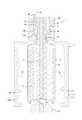
このような本発明の容器製造方法は、例えば図1〜図7に示す構成の液体ブロー成形装置1を用いて実施することができる。 Such a container manufacturing method of the present invention can be implemented using, for example, the liquid blow molding apparatus 1 having the configuration shown in FIGS.
液体ブロー成形装置1は、合成樹脂製のプリフォームPFを液体ブロー成形することにより、内部に液体(内容液)Lを収容するとともに所定の大きさのヘッドスペースHSを有する液体入りの容器Cを製造するものである。なお、液体ブロー成形とは、プリフォームPFに加圧した液体Lを供給して、プリフォームPFをブロー成形型11のキャビティ12に沿った形状の容器Cに成形するブロー成形のことである。 The liquid blow molding apparatus 1 performs liquid blow molding of a preform PF made of a synthetic resin to accommodate a liquid (content liquid) L therein and a liquid-containing container C having a headspace HS of a predetermined size. It is manufactured. In addition, the liquid blow molding refers to blow molding in which the pressurized liquid L is supplied to the preform PF and the preform PF is molded into a container C shaped along the
液体ブロー成形においてプリフォームPFに供給される液体Lとしては、成形後の容器Cに収容されて内容液Lとなる液体が用いられる。このような液体Lとしては、例えば飲料、化粧品、薬品、洗剤、シャンプー等のトイレタリーなどの様々な液体を用いることができる。 As the liquid L supplied to the preform PF in the liquid blow molding, a liquid that is contained in the molded container C and becomes the content liquid L is used. As such a liquid L, for example, various liquids such as beverages, cosmetics, medicines, detergents, toiletries such as shampoos and the like can be used.
プリフォームPFとしては、例えば、ポリプロピレン(PP)やポリエチレンテレフタレート(PET)等の熱可塑性を有する合成樹脂材料を原材料とし、射出成形やダイレクトブロー成形、押出し成形等を行うことによって、開口端となる円筒状の口部PFaと口部PFaに連なるとともに下端が閉塞された有底円筒状の胴部PFbとを有する略試験管状に形成されたものを用いることができる。 As the preform PF, for example, a synthetic resin material having thermoplasticity such as polypropylene (PP) or polyethylene terephthalate (PET) is used as a raw material, and an opening end is obtained by performing injection molding, direct blow molding, extrusion molding, or the like. A substantially test tube having a cylindrical mouth PFa and a bottomed cylindrical body PFb connected to the mouth PFa and having a closed lower end can be used.
プリフォームPFとしては、上記形状のものに限らず、成形後の容器Cの形状や材質等に応じて種々の形状ないし材質のものを用いることができる。 The preform PF is not limited to the above-mentioned shape, and various shapes and materials can be used according to the shape and material of the container C after molding.
口部PFaの外壁面には、成形後の容器Cの口部Caに、口部Caを閉塞する閉塞キャップ、注出ノズル等を備えた注出キャップ、又はポンプ付き吐出装置の装着キャップ等(不図示)を装着するための雄ねじPFcが一体に設けられている。なお、口部PFaの外壁面に、雄ねじPFcに替えて前述のような種々のキャップを打栓(アンダーカット係合)によって装着するための係合突起を設けた構成とすることもできる。 On the outer wall surface of the mouth PFa, a closing cap for closing the mouth Ca, a pouring cap provided with a pouring nozzle, a mounting cap of a discharge device with a pump, etc. A male screw PFc for mounting a (not shown) is integrally provided. It should be noted that the outer wall surface of the mouth PFa may be provided with an engagement projection for mounting the above-described various caps by tapping (undercut engagement) instead of the male screw PFc.
プリフォームPFは、ヒーター等の加熱手段を用いて延伸性を発現する所定の温度にまで予め加熱された後、図1に示すように、胴部PFbがキャビティ12の内部に配置されるとともに口部PFaがキャビティ12から上方に突出する起立姿勢でブロー成形型11に配置される。 The preform PF is preheated to a predetermined temperature at which the preform PF develops extensibility by using a heating means such as a heater, and then, as shown in FIG. The portion PFa is disposed on the
ブロー成形型11のキャビティ12は、例えばボトル形状などの容器の最終形状に対応した形状に形成されている。キャビティ12はブロー成形型11の上面において上方に向けて開口しており、当該開口から上記のようにプリフォームPFの口部PFaを上方に突出させることができる。 The
ブロー成形型11は外周型部11aと底型部11bとを有し、これらを組み合わせて構成されている。 The
外周型部11aは、キャビティ12の、容器Cの胴部Cbに対応した部分を区画形成するものである。外周型部11aは左右一対の分離型片11a1、11a2を有し、左右に分離可能な構成となっている。キャビティ12は一対の分離型片11a1、11a2に対応するように左右対称に分割されている。外周型部11aは容器Cないしキャビティ12の軸心を中心として当該軸心の径方向に向けて分離することができる。ブロー成形型11は、外周型部11aを、一対の分離型片11a1、11a2を互いに離反する方向に移動させて左右に型開きさせることにより開放可能となっている。プリフォームPFを液体ブロー成形によって容器Cに成形した後に、上記のようにブロー成形型11を開放することにより、当該成形後の容器Cをブロー成形型11から取り出すことができる。 The outer
なお、本実施の形態においては、外周型部11aを左右一対の分離型片11a1、11a2に分離可能な構成としているが、これに限らず、複数の分離型片に分離されてブロー成形型11を開放可能な構成であれば、例えば、外周型部11aを周方向に3分割した構成とし、あるいは外周型部11aを一対の分離型片に分割可能とするとともにこれらの分割型片を一方の分割面の側において互いにヒンジで連結し、他方の分割面が互いに離間するように回動式に開放させる構成とするなど、その分割形態は種々変更可能である。 In the present embodiment, the outer
底型部11bは、キャビティ12の、容器Cの底部Ccに対応した部分を区画形成するものであり、上向き凸状の形状を有している。図3に示すように、底型部11bは外周型部11aに対して下方に向けて移動可能となっており、プリフォームPFを液体ブロー成形によって容器Cに成形した後、下方に向けて移動することにより、容器Cの上向き凸状に成形された底部Ccから退避することができるようになっている。 The
底型部11bには、これの軸心を上下方向に貫通する迎えピン13が設けられている。迎えピン13は底型部11bに埋没する位置からキャビティ12の内部に突出する位置との間で、当該キャビティ12の軸心に沿って上下方向に移動自在となっている。なお、迎えピン13を設けない構成としてもよい。 The
ブロー成形型11の上側には、ブロー成形型11に対して上下方向に相対移動自在にノズルユニット20が設けられている。ノズルユニット20は本体ブロック21と充填ノズル22とを有している。 A
充填ノズル22は、プリフォームPFの口部PFaの内部に挿入される円筒状に形成されたノズル本体22aとこのノズル本体22aと一体に形成された大径の挟持部22bとが、例えば鋼材や樹脂材料等により一体に形成された構成となっている。充填ノズル22は、挟持部22bが本体ブロック21の内面に嵌め込まれることにより本体ブロック21に固定されている。ノズル本体22aは、ブロー成形型11のキャビティ12と同軸に配置されており、ノズルユニット20が所定位置にまで下降するとブロー成形型11に装着されたプリフォームPFの口部PFaに係合するようになっている。 The filling
本体ブロック21の内部にはノズル本体22aと同軸となって上下方向に延びる液体供給路23が設けられている。この液体供給路23は充填ノズル22に液体Lを供給するための流路であり、その下端において充填ノズル22に連通している。 Inside the
液体供給路23には配管24を介して加圧液体供給部25が接続されている。加圧液体供給部25は、配管24を介して液体供給路23に所定の圧力にまで加圧した液体Lを供給することができる。加圧液体供給部25としては、例えば加圧源としてプランジャーポンプを用いた構成のものを用いることができる。 A pressurized
加圧液体供給部25から液体供給路23に加圧された液体Lが供給されると、液体Lは液体供給路23から充填ノズル22を介してブロー成形型11に配置されたプリフォームPFの内部に供給される。これにより、プリフォームPFが加圧された液体Lによってブロー成形型11のキャビティ12に沿った形状の容器Cに液体ブロー成形される。 When the pressurized liquid L is supplied from the pressurized
液体供給路23の内部には、充填ノズル22を液体供給路23に対して開閉するためのシール体26が配置されている。シール体26は液体供給路23の軸心に沿って延びる円筒状に形成されており、液体供給路23の内部で上下方向に移動自在となっている。シール体26が下方のストローク端にまで移動してその下端面が挟持部22bの上面に当接すると、液体供給路23とノズル本体22aとの連通がシール体26によって遮断され、充填ノズル22は液体供給路23に対して閉じられた状態となる。一方、シール体26が閉じた状態から上方に移動し、その下端面が挟持部22bの上面から離れると、液体供給路23とノズル本体22aとが連通され、充填ノズル22は液体供給路23に対して開かれた状態となる。 Inside the
したがって、ノズル本体22aをプリフォームPFの口部PFaに係合させ、シール体26を開いて液体供給路23を充填ノズル22に連通させた状態で加圧液体供給部25を作動させることで、加圧液体供給部25から液体供給路23及び充填ノズル22を介してプリフォームPFの内部に加圧された液体Lを供給してプリフォームPFを液体ブロー成形することができる。 Therefore, the
図示するように、液体ブロー成形装置1は延伸ロッド27を備えた構成とすることもできる。延伸ロッド27は、シール体26の軸心に該シール体26に対して上下方向に相対移動自在に挿入されており、シール体26の下端からキャビティ12の内部に向けて出没可能となっている。延伸ロッド27を下方に向けて進出移動させることにより、プリフォームPFを当該延伸ロッド27により軸方向に延伸させることができる。このように、延伸ロッド27を設けた構成とした場合には、液体ブロー成形装置1は、プリフォームPFを延伸ロッド27により軸方向に延伸させつつ加圧した液体Lにより径方向に延伸させる二軸延伸ブロー成形を行うことができる。このとき、迎えピン13でプリフォームPFの胴部PFbの底部分を支持しながら二軸延伸ブロー成形を行うことで、プリフォームPFの芯ずれを抑制して、より精度よく容器Cに成形することができる。 As shown in the drawing, the liquid blow molding device 1 can be configured to include a stretching
なお、液体ブロー成形装置1は、延伸ロッド27を備えない構成とすることもできる。 In addition, the liquid blow molding apparatus 1 may be configured not to include the stretching
液体ブロー成形装置1には、プリフォームPFを液体ブロー成形した後、ブロー成形型11を開放した状態で成形後の容器Cの胴部Cbを押圧し、当該容器Cの内部の液体Lを所定量だけ容器Cの外部(本実施の形態では液体供給路23)に排出させるための一対の押圧部28が設けられている。 After the preform PF is subjected to liquid blow molding, the body Cb of the molded container C is pressed in a state where the blow molding die 11 is opened, and the liquid L inside the container C is placed in the liquid blow molding apparatus 1. A pair of
これらの押圧部28は、それぞれ鋼材等により棒状に形成され、キャビティ12の軸心を挟んで互いに先端を対向させた水平姿勢に配置されている。押圧部28はそれぞれ、図示しない駆動部により駆動され、互いの先端を接近させる方向に移動することができる。 Each of these
図5に示すように、これらの押圧部28は、外周型部11aの分割面つまり一対の分離型片11a1、11a2が組み合わされる面に沿って配置され、プリフォームPFが液体ブロー成形により容器Cに成形された後、一対の分離型片11a1、11a2が互いに離反する方向に移動してブロー成形型11が開放されたときに、隣り合う分離型片11a1、11a2の隙間から容器Cの胴部Cbに向けて挿通される。そして、押圧部28は、その先端において成形後の容器Cの胴部Cbに側方から当接するとともに当該胴部Cbをその内側に向けて押圧して、容器Cの内部の液体Lをその口部Caから外部つまり充填ノズル22を通して液体供給路23に排出させる。 As shown in FIG. 5, these
このとき、一対の押圧部28によって胴部Cbを挟み込んだ状態で押圧することにより、当該胴部Cbをより効果的に押圧することができる。 At this time, by pressing the body Cb with the pair of
なお、上記の通り、押圧部28は、外周型部11aの分割面つまり一対の分離型片11a1、11a2が組み合わされる面に沿って配置されるが、図1〜図3においては便宜上、二点鎖線を用いて押圧部28を分離型片11a1、11a2の背面側に示す。 As described above, the
次に、このような構成の液体ブロー成形装置1を用いて、合成樹脂製のプリフォームPFを液体ブロー成形して内容液Lを収容した所定形状の容器Cを製造する方法(本発明の容器製造方法)について説明する。 Next, using the liquid blow molding apparatus 1 having such a configuration, a method of manufacturing a container C having a predetermined shape containing the content liquid L by performing liquid blow molding of a preform PF made of synthetic resin (the container of the present invention) The manufacturing method will be described.
まず、プリフォームセット工程が行われる。プリフォームセット工程においては、図1に示すように、予めヒーター等の加熱手段(不図示)を用いて延伸性を発現する程度の所定の温度(例えば80℃〜150℃)にまで加熱しておいたプリフォームPFをブロー成形型11に配置し、型締めするとともに、ノズルユニット20を下降させ、充填ノズル22のノズル本体22aをプリフォームPFの口部PFaに係合させる。なお、プリフォームセット工程においては、充填ノズル22はシール体26によって閉じた状態とされ、加圧液体供給部25は停止している。 First, a preform setting step is performed. In the preform setting step, as shown in FIG. 1, heating is performed beforehand to a predetermined temperature (for example, 80 ° C. to 150 ° C.) using a heating means such as a heater (not shown) so as to exhibit stretchability. The placed preform PF is placed in the blow molding die 11, the mold is clamped, the
プリフォームセット工程が完了すると、次にブロー成形工程が行われる。ブロー成形工程においては、図2に示すように、シール体26を上方に移動させて充填ノズル22を開くとともに加圧液体供給部25を作動させる。これにより、加圧液体供給部25から液体供給路23に加圧した液体Lが供給されるとともに、当該液体Lが充填ノズル22を通って口部PFaからプリフォームPFの内部に供給される。そして、プリフォームPFの内部に加圧した液体Lが供給されることにより、プリフォームPFがブロー成形型11のキャビティ12に沿った形状の容器Cに液体ブロー成形される。 When the preform setting step is completed, a blow molding step is performed next. In the blow molding step, as shown in FIG. 2, the sealing
ブロー成形工程においては、延伸ロッド27を用いてプリフォームPFを縦方向(軸方向)に延伸することにより二軸延伸ブロー成形を行うことができる。このとき、延伸ロッド27による軸方向の延伸中または延伸後に液体Lの供給が開始されてもよい。二軸延伸ブロー成形によれば、成形中におけるプリフォームPFの芯ずれを抑制することができる。なお、延伸ロッド27は最初からプリフォームPFを延伸させる必要はなく、液体LのみによってプリフォームPFを軸方向に或る程度延伸させた後に、延伸ロッド27でプリフォームPFをさらに軸方向に延伸させるようにしてもよい。 In the blow molding step, biaxial stretch blow molding can be performed by stretching the preform PF in the longitudinal direction (axial direction) using the stretching
また、このとき、迎えピン13でプリフォームPFの胴部PFbの底部分を支持しながら(すなわち、延伸ロッド27の下端部と迎えピン13の上端部で挟持しながら)軸方向に延伸させることができる。このような構成とすることで、成形中におけるプリフォームPFの芯ずれをより確実に抑制することができる。なお、迎えピン13は最初からプリフォームPFを支持する必要はなく、プリフォームPFを軸方向に或る程度延伸させた後に迎えピン13でプリフォームPFを支持するようにしてもよい。 At this time, the preform PF is extended in the axial direction while supporting the bottom portion of the body portion PFb of the preform PF with the pickup pin 13 (that is, while holding the lower end of the
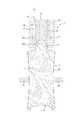
ブロー成形工程が完了すると、次に液体排出工程が行われる。液体排出工程においては、まず、図3に示すように、充填ノズル22を開き、加圧液体供給部25が停止した状態のままブロー成形型11を開放する。 When the blow molding step is completed, a liquid discharging step is performed next. In the liquid discharging step, first, as shown in FIG. 3, the filling
次いで、図4、図5に示すように、充填ノズル22を開き、ブロー成形型11を開放した状態のまま、隣り合う分離型片11a1、11a2の隙間に押圧部28を挿通し、当該押圧部28により成形後の容器Cの胴部Cbを押圧する。これにより、容器Cの胴部Cbが一対の押圧部28で挟み込まれてその内容量が減少するように扁平形状に弾性変形し、容器Cの内部に収容されている液体Lが所定量だけ口部Caから容器Cの外部に排出される。容器Cの口部Caから排出された液体Lは、充填ノズル22を通して液体供給路23に戻されることになる。なお、容器Cの内部から排出させる液体Lの量は、押圧部28の押込み量を変更することによって所望の量に設定することができる。このように、容器Cの胴部Cbを変形させて所定量の液体Lを成形後の容器Cの内部から排出させることにより、容器Cはその内部に満注容量よりも少ない液体Lが収容された状態となる。 Next, as shown in FIGS. 4 and 5, while the filling
なお、本実施の形態においては、ブロー成形工程を行った後、充填ノズル22を液体供給路23に対して開いた状態に維持したままブロー成形型11の開放と押圧部28による容器Cの胴部Cbの押圧とを行うようにしているが、ブロー成形工程の完了時に充填ノズル22を液体供給路23に対して閉じてからブロー成形型11を開放し、再度、充填ノズル22を液体供給路23に対して開いてから押圧部28により容器Cの胴部Cbを押圧して容器Cの内部の液体Lを充填ノズル22を通して液体供給路23に排出させるようにしてもよい。 In the present embodiment, after performing the blow molding step, the blow molding die 11 is opened and the cylinder of the container C is pressed by the
本実施の形態のように、ブロー成形工程において延伸ロッド27を用いた二軸延伸ブロー成形を行った場合には、延伸ロッド27を成形後の容器Cの内部から引き抜いてから押圧部28による胴部Cbの押圧を行うのが好ましい。これにより、延伸ロッド27を容器Cの内部から引き抜く際に容器Cが減圧変形を生じるのを防止して、容器Cの内部に形成されるヘッドスペースの大きさをより精度よく設定することができる。 In the case where biaxial stretching blow molding using the stretching
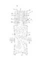
液体排出工程が完了すると、次にヘッドスペース形成工程が行われる。ヘッドスペース形成工程においては、まず、図6に示すように、押圧部28により容器Cの胴部Cbを押圧した状態のまま、つまり容器Cを所定量の液体Lを外部に排出した状態としたまま、充填ノズル22を液体供給路23に対して閉じ、液体供給路23と容器Cの内部との連通を遮断する。 When the liquid discharging step is completed, a head space forming step is performed next. In the head space forming step, first, as shown in FIG. 6, the state where the body Cb of the container C is pressed by the
次いで、図7に示すように、押圧部28を容器Cの胴部Cbから離れる原位置にまで復帰させるとともにノズルユニット20を原位置にまで上昇させて充填ノズル22を口部Caから離脱させる。このとき、充填ノズル22が液体供給路23に対して閉じられて液体供給路23と容器Cの内部との連通は遮断されているので、充填ノズル22を離脱させる際に液体供給路23から容器Cに液体Lが戻ることはない。これにより、容器Cの胴部Cbは液体ブロー成形が完了した時の形状に復元し、その内部に所望の大きさのヘッドスペースHSが精度よく形成される。 Next, as shown in FIG. 7, the
このように、本発明の容器製造方法によれば、プリフォームPFを液体ブロー成形した後にブロー成形型11を開放し、ブロー成形型11とは別に設けられた押圧部28を当該ブロー成形型11の分離型片11a1、11a2の隙間から挿通して成形後の容器Cの胴部Cbを押圧し、これにより容器Cの内部の液体Lを所定量だけ外部に排出させて容器Cの内部にヘッドスペースHSを形成するようにしたので、ブロー成形型11として押圧部28に相当する部材を内蔵した複雑な構成のものを用いることなく、容器Cの内部に所望の大きさのヘッドスペースHSを形成することができる。特に、ブロー成形型11として複数のキャビティ12を直列に配置した構成のものを用い、複数のプリフォームPFを一度に液体ブロー成形して複数の容器Cを製造するようにしたバッチ式の液体ブロー成形装置においても、複数のキャビティ12に対応した複数組の押圧部28を当該ブロー成形型11の構成を複雑化させることなく容易に配置することができる。したがって、簡単な構成のブロー成形型11を用いることで、この容器Cの製造コストを低減することができる。 As described above, according to the container manufacturing method of the present invention, after the preform PF is subjected to liquid blow molding, the blow molding die 11 is opened, and the
また、本実施の形態においては、液体排出工程において、容器Cから排出した液体Lを、充填ノズル22を通して液体供給路23に戻すようにしたので、液体Lの消費量を低減させることができるとともに、液体Lを排出するための流路を別途設けることを不要として液体ブロー成形装置1の構成を簡略化させることができる。したがって、この容器Cの製造コストをさらに低減することができる。 Further, in the present embodiment, in the liquid discharging step, the liquid L discharged from the container C is returned to the
図8は本発明の容器製造方法における液体排出工程及びヘッドスペース形成工程の変形例を説明するための縦断面図である。なお、図8においては前述した部材に対応する部材には同一の符号を付してある。 FIG. 8 is a longitudinal sectional view for explaining a modification of the liquid discharging step and the headspace forming step in the container manufacturing method of the present invention. In FIG. 8, members corresponding to those described above are denoted by the same reference numerals.
図1〜図7に示す場合では、液体排出工程において、充填ノズル22を液体供給路23に対して開いたまま押圧部28により容器Cの胴部Cbを押圧して容器Cから排出した液体Lを充填ノズル22を通して液体供給路23に戻すようにしているが、図8に示すように、容器Cから排出した液体Lを、充填ノズル22から分岐して設けられた排出路30を通して容器Cの外部に排出する構成とすることもできる。 In the case shown in FIGS. 1 to 7, in the liquid discharging step, the liquid L discharged from the container C by pressing the body Cb of the container C by the
この場合、液体排出工程においては、充填ノズル22を液体供給路23に対して閉じるとともに排出路30に設けられた開閉バルブ31を開いた状態として押圧部28により容器Cの胴部Cbを押圧する。これにより、容器Cの内部に収容されている液体Lを所定量だけ排出路30を通して外部に排出させることができる。 In this case, in the liquid discharging step, the filling
一方、ヘッドスペース形成工程においては、排出路30を開閉バルブ31によって閉じてから充填ノズル22を容器Cの口部Caから離脱させる。これにより、充填ノズル22を離脱させる際に排出路30に残った液体Lが口部Caから容器Cに戻ることを防止して、当該容器Cの内部に所望の大きさのヘッドスペースHSを精度よく形成することができる。 On the other hand, in the head space forming step, the
本発明は前記実施の形態に限定されるものではなく、その要旨を逸脱しない範囲で種々変更可能であることはいうまでもない。 The present invention is not limited to the above embodiment, and it goes without saying that various changes can be made without departing from the spirit of the present invention.
例えば、前記実施の形態では、図1〜図8に示す構成の液体ブロー成形装置1を用いて本発明の容器製造方法を行う場合を示したが、他の構成の液体ブロー成形装置等を用いて本発明の容器製造方法を行うこともできる。 For example, in the above embodiment, the case where the container manufacturing method of the present invention is performed using the liquid blow molding apparatus 1 having the configuration shown in FIGS. 1 to 8 has been described. However, the liquid blow molding apparatus having another configuration is used. Thus, the container manufacturing method of the present invention can be performed.
また、前記実施の形態では、ブロー成形工程において延伸ロッド27を用いて二軸延伸ブロー成形を行うようにしているが、延伸ロッド27による延伸を行わない構成とすることもできる。 In the above-described embodiment, the biaxial stretching blow molding is performed using the stretching
さらに、本発明の容器製造方法は、シャンプー等を内容液として収容するポンプ付き容器に用いられる液体入りの容器Cのように、その内部に大きなヘッドスペースHSを有するものを製造する場合に限らず、ヘッドスペースHSの大小に拘わらず種々の液体入りの容器Cの製造に適用することができる。 Further, the container manufacturing method of the present invention is not limited to the case of manufacturing a container having a large head space HS therein, such as a container C containing a liquid used for a container with a pump for storing a shampoo or the like as a content liquid. It can be applied to the production of containers C containing various liquids regardless of the size of the head space HS.
さらに、前記実施の形態では、ブロー成形型11の開放時に底型部11bを下降させるようにしているが、底型部11bを下降させることなく押圧部28による押圧時に容器Cを底型部11bで支持する構成とすることもできる。 Further, in the above-described embodiment, the
1 液体ブロー成形装置
11 ブロー成形型
11a 外周型部
11a1 分離型片
11a2 分離型片
11b 底型部
12 キャビティ
13 迎えピン
20 ノズルユニット
21 本体ブロック
22 充填ノズル
22a ノズル本体
22b 挟持部
23 液体供給路
24 配管
25 加圧液体供給部
26 シール体
27 延伸ロッド
28 押圧部
30 排出路
31 開閉バルブ
PF プリフォーム
PFa 口部
PFb 胴部
PFc 雄ねじ
L 液体(内容液)
HS ヘッドスペース
C 容器
Ca 口部
Cb 胴部
Cc 底部DESCRIPTION OF SYMBOLS 1 Liquid
HS Headspace C Container Ca Mouth Cb Trunk Cc Bottom
Claims (5)
Translated fromJapanese複数の分離型片に分離することで開放可能なブロー成形型に前記プリフォームを配置するとともに、液体供給路に接続された充填ノズルを前記プリフォームの口部に係合させるプリフォームセット工程と、
前記液体供給路に供給された加圧された液体を前記充填ノズルから前記プリフォームの内部に供給して該プリフォームを前記ブロー成形型のキャビティに沿った形状に液体ブロー成形するブロー成形工程と、
前記ブロー成形型を開放し、隣り合う前記分離型片の隙間から挿通した押圧部により成形後の容器の胴部を押圧して該容器の内部の液体を所定量だけ該容器の外部に排出させる液体排出工程と、
所定量の液体を外部に排出した状態の前記容器の口部から前記充填ノズルを離脱させて該容器の内部にヘッドスペースを形成するヘッドスペース形成工程と、を有することを特徴とする容器製造方法。A container manufacturing method for manufacturing a container containing a content liquid by liquid blow molding a synthetic resin preform,
A preform setting step of disposing the preform in a blow mold that can be opened by separating the preform into a plurality of separation mold pieces, and engaging a filling nozzle connected to a liquid supply path with an opening of the preform. ,
A blow molding step of supplying the pressurized liquid supplied to the liquid supply path from the filling nozzle to the inside of the preform and performing liquid blow molding of the preform into a shape along the cavity of the blow mold. ,
The blow molding die is opened, and the body of the molded container is pressed by the pressing portion inserted from the gap between the adjacent separated mold pieces to discharge a predetermined amount of liquid inside the container to the outside of the container. A liquid discharging process,
A method for manufacturing a container, comprising: detaching the filling nozzle from an opening of the container in a state where a predetermined amount of liquid has been discharged to the outside to form a head space inside the container. .
前記ヘッドスペース形成工程において、前記充填ノズルを前記液体供給路に対して閉じてから該充填ノズルを前記口部から離脱させる、請求項1に記載の容器製造方法。In the liquid discharging step, the pressing portion presses the body of the container with the filling nozzle opened to the liquid supply passage, and the liquid inside the container is supplied to the liquid supply passage through the filling nozzle. Back,
2. The container manufacturing method according to claim 1, wherein in the head space forming step, the filling nozzle is separated from the opening after closing the filling nozzle with respect to the liquid supply path. 3.
前記ヘッドスペース形成工程において、前記排出路を閉じてから前記充填ノズルを前記口部から離脱させる、請求項1に記載の容器製造方法。In the liquid discharging step, the filling part is closed with respect to the liquid supply path, and the body of the container is pressed by the pressing part in a state where the discharge path branched from the filling nozzle is opened. Discharging the liquid to the outside through the discharge path,
The container manufacturing method according to claim 1, wherein, in the headspace forming step, the filling nozzle is separated from the opening after closing the discharge path.
前記液体排出工程において、前記延伸ロッドを成形後の前記容器の内部から引き抜いてから前記押圧部によって成形後の前記容器の胴部を押圧する、請求項1〜4の何れか1項に記載の容器製造方法。In the blow molding step, the preform is stretched in the axial direction by a stretching rod,
5. The liquid discharging step according to claim 1, wherein the stretching rod is pulled out from the inside of the molded container, and then the body of the molded container is pressed by the pressing portion. 6. Container manufacturing method.
Priority Applications (5)
| Application Number | Priority Date | Filing Date | Title |
|---|---|---|---|
| JP2016109366AJP6661477B2 (en) | 2016-05-31 | 2016-05-31 | Container manufacturing method |
| CN201780026533.9ACN109070432B (en) | 2016-05-31 | 2017-03-21 | Container manufacturing method |
| PCT/JP2017/011236WO2017208574A1 (en) | 2016-05-31 | 2017-03-21 | Container manufacturing method |
| EP17806136.2AEP3466640B1 (en) | 2016-05-31 | 2017-03-21 | Container production method |
| US16/095,743US11465329B2 (en) | 2016-05-31 | 2017-03-21 | Container production method |
Applications Claiming Priority (1)
| Application Number | Priority Date | Filing Date | Title |
|---|---|---|---|
| JP2016109366AJP6661477B2 (en) | 2016-05-31 | 2016-05-31 | Container manufacturing method |
Publications (2)
| Publication Number | Publication Date |
|---|---|
| JP2017213779A JP2017213779A (en) | 2017-12-07 |
| JP6661477B2true JP6661477B2 (en) | 2020-03-11 |
Family
ID=60479326
Family Applications (1)
| Application Number | Title | Priority Date | Filing Date |
|---|---|---|---|
| JP2016109366AActiveJP6661477B2 (en) | 2016-05-31 | 2016-05-31 | Container manufacturing method |
Country Status (5)
| Country | Link |
|---|---|
| US (1) | US11465329B2 (en) |
| EP (1) | EP3466640B1 (en) |
| JP (1) | JP6661477B2 (en) |
| CN (1) | CN109070432B (en) |
| WO (1) | WO2017208574A1 (en) |
Families Citing this family (7)
| Publication number | Priority date | Publication date | Assignee | Title |
|---|---|---|---|---|
| JP6802741B2 (en) | 2017-03-27 | 2020-12-16 | 株式会社吉野工業所 | Container manufacturing method |
| JP6864573B2 (en)* | 2017-06-30 | 2021-04-28 | 株式会社吉野工業所 | Manufacturing method of liquid container |
| DE102018125794A1 (en)* | 2018-10-17 | 2020-04-23 | Krones Ag | Mold filling with subsequent sealing under internal pressure |
| DE102019114953A1 (en)* | 2019-06-04 | 2020-12-10 | Khs Corpoplast Gmbh | Method and device for the production of containers filled with liquid contents from thermally conditioned preforms |
| WO2021255504A1 (en)* | 2020-06-19 | 2021-12-23 | Discma Ag | Method of fluid forming and filling containers |
| CN111873374B (en)* | 2020-09-28 | 2020-12-08 | 长沙水星包装有限公司 | Polycarbonate purified water bucket blow molding system |
| JP7693494B2 (en)* | 2021-09-30 | 2025-06-17 | 株式会社吉野工業所 | Manufacturing method of liquid-filled container |
Family Cites Families (15)
| Publication number | Priority date | Publication date | Assignee | Title |
|---|---|---|---|---|
| DE3834184C1 (en)* | 1988-10-07 | 1989-12-28 | Bernd 7166 Sulzbach-Laufen De Hansen | |
| JP4069511B2 (en)* | 1998-08-20 | 2008-04-02 | 凸版印刷株式会社 | Method for manufacturing liquid container |
| US6485670B1 (en)* | 1999-11-09 | 2002-11-26 | Schmalbach-Lubeca Ag | Blow molding method for producing pasteurizable containers |
| JP5503222B2 (en)* | 2009-08-11 | 2014-05-28 | 日精エー・エス・ビー機械株式会社 | Large returnable container, molding method and molding apparatus thereof, and blow mold divided into heating zones |
| DE102010007541A1 (en)* | 2009-12-23 | 2011-06-30 | KHS Corpoplast GmbH, 22145 | Method and device for producing filled containers |
| FR2962930B1 (en)* | 2010-07-20 | 2012-08-31 | Sidel Participations | PROCESS FOR FORMING A CONTAINER BY BLOWING AND FILLING |
| CA2827087C (en)* | 2011-02-16 | 2019-12-03 | Amcor Limited | Blow nozzle to control liquid flow with pre-stretch rod assembly and metal seat seal pin |
| US9610744B2 (en)* | 2011-12-27 | 2017-04-04 | Discma Ag | Blow molding device and a method for manufacturing a container |
| JP5919127B2 (en)* | 2012-07-31 | 2016-05-18 | 株式会社吉野工業所 | Blow molding apparatus and method for producing synthetic resin container |
| WO2013147065A1 (en) | 2012-03-30 | 2013-10-03 | 株式会社吉野工業所 | Method for manufacturing container containing content fluid, method for pressurizing interior of container, filled container, blow-molding method, and blow-molding device |
| JP6280135B2 (en) | 2012-12-19 | 2018-02-14 | ディスクマ アクチェンゲゼルシャフト | Container, and apparatus and method for manufacturing and filling the container |
| JP6184851B2 (en) | 2013-11-28 | 2017-08-23 | 株式会社吉野工業所 | Mold for blow molding |
| WO2015136369A2 (en)* | 2014-03-10 | 2015-09-17 | Discma Ag | Method of forming and setting headspace within a container |
| JP6433754B2 (en)* | 2014-10-24 | 2018-12-05 | 株式会社吉野工業所 | Polypropylene preform |
| JP6511359B2 (en)* | 2014-10-30 | 2019-05-15 | 株式会社吉野工業所 | Container manufacturing method |
- 2016
- 2016-05-31JPJP2016109366Apatent/JP6661477B2/enactiveActive
- 2017
- 2017-03-21WOPCT/JP2017/011236patent/WO2017208574A1/ennot_activeCeased
- 2017-03-21USUS16/095,743patent/US11465329B2/enactiveActive
- 2017-03-21CNCN201780026533.9Apatent/CN109070432B/enactiveActive
- 2017-03-21EPEP17806136.2Apatent/EP3466640B1/enactiveActive
Also Published As
| Publication number | Publication date |
|---|---|
| JP2017213779A (en) | 2017-12-07 |
| US20190240891A1 (en) | 2019-08-08 |
| EP3466640B1 (en) | 2021-03-31 |
| US11465329B2 (en) | 2022-10-11 |
| WO2017208574A1 (en) | 2017-12-07 |
| CN109070432A (en) | 2018-12-21 |
| CN109070432B (en) | 2020-08-14 |
| EP3466640A1 (en) | 2019-04-10 |
| EP3466640A4 (en) | 2020-01-15 |
Similar Documents
| Publication | Publication Date | Title |
|---|---|---|
| JP6661477B2 (en) | Container manufacturing method | |
| US10189202B2 (en) | Blow molding device | |
| JP2018183973A (en) | Manufacturing method of container containing liquid | |
| JP2019025819A (en) | Manufacturing apparatus and manufacturing method for liquid container | |
| US20200361133A1 (en) | Liquid-containing container manufacturing method | |
| JP6802741B2 (en) | Container manufacturing method | |
| JP6751306B2 (en) | Container manufacturing method by liquid blow molding | |
| EP3632652B1 (en) | Liquid container manufacturing method | |
| JP6864573B2 (en) | Manufacturing method of liquid container | |
| EP3278953B1 (en) | Liquid blow molding apparatus | |
| EP3888882B1 (en) | Blow molding device | |
| JP7506004B2 (en) | Manufacturing method of liquid-filled container |
Legal Events
| Date | Code | Title | Description |
|---|---|---|---|
| A621 | Written request for application examination | Free format text:JAPANESE INTERMEDIATE CODE: A621 Effective date:20181205 | |
| A131 | Notification of reasons for refusal | Free format text:JAPANESE INTERMEDIATE CODE: A131 Effective date:20191029 | |
| A521 | Request for written amendment filed | Free format text:JAPANESE INTERMEDIATE CODE: A523 Effective date:20191219 | |
| TRDD | Decision of grant or rejection written | ||
| A01 | Written decision to grant a patent or to grant a registration (utility model) | Free format text:JAPANESE INTERMEDIATE CODE: A01 Effective date:20200114 | |
| A61 | First payment of annual fees (during grant procedure) | Free format text:JAPANESE INTERMEDIATE CODE: A61 Effective date:20200212 | |
| R150 | Certificate of patent or registration of utility model | Ref document number:6661477 Country of ref document:JP Free format text:JAPANESE INTERMEDIATE CODE: R150 |