JP6659578B2 - Method and apparatus for selecting a sensing vector configuration on a medical device - Google Patents
Method and apparatus for selecting a sensing vector configuration on a medical deviceDownload PDFInfo
- Publication number
- JP6659578B2 JP6659578B2JP2016564141AJP2016564141AJP6659578B2JP 6659578 B2JP6659578 B2JP 6659578B2JP 2016564141 AJP2016564141 AJP 2016564141AJP 2016564141 AJP2016564141 AJP 2016564141AJP 6659578 B2JP6659578 B2JP 6659578B2
- Authority
- JP
- Japan
- Prior art keywords
- vector
- sensing
- metric
- determined
- vectors
- Prior art date
- Legal status (The legal status is an assumption and is not a legal conclusion. Google has not performed a legal analysis and makes no representation as to the accuracy of the status listed.)
- Active
Links
Images


Classifications
- A—HUMAN NECESSITIES
- A61—MEDICAL OR VETERINARY SCIENCE; HYGIENE
- A61B—DIAGNOSIS; SURGERY; IDENTIFICATION
- A61B5/00—Measuring for diagnostic purposes; Identification of persons
- A61B5/24—Detecting, measuring or recording bioelectric or biomagnetic signals of the body or parts thereof
- A61B5/316—Modalities, i.e. specific diagnostic methods
- A61B5/318—Heart-related electrical modalities, e.g. electrocardiography [ECG]
- A61B5/339—Displays specially adapted therefor
- A61B5/341—Vectorcardiography [VCG]
- A—HUMAN NECESSITIES
- A61—MEDICAL OR VETERINARY SCIENCE; HYGIENE
- A61N—ELECTROTHERAPY; MAGNETOTHERAPY; RADIATION THERAPY; ULTRASOUND THERAPY
- A61N1/00—Electrotherapy; Circuits therefor
- A61N1/18—Applying electric currents by contact electrodes
- A61N1/32—Applying electric currents by contact electrodes alternating or intermittent currents
- A61N1/36—Applying electric currents by contact electrodes alternating or intermittent currents for stimulation
- A61N1/362—Heart stimulators
- A61N1/3621—Heart stimulators for treating or preventing abnormally high heart rate
- A—HUMAN NECESSITIES
- A61—MEDICAL OR VETERINARY SCIENCE; HYGIENE
- A61B—DIAGNOSIS; SURGERY; IDENTIFICATION
- A61B5/00—Measuring for diagnostic purposes; Identification of persons
- A61B5/24—Detecting, measuring or recording bioelectric or biomagnetic signals of the body or parts thereof
- A61B5/25—Bioelectric electrodes therefor
- A—HUMAN NECESSITIES
- A61—MEDICAL OR VETERINARY SCIENCE; HYGIENE
- A61B—DIAGNOSIS; SURGERY; IDENTIFICATION
- A61B5/00—Measuring for diagnostic purposes; Identification of persons
- A61B5/24—Detecting, measuring or recording bioelectric or biomagnetic signals of the body or parts thereof
- A61B5/316—Modalities, i.e. specific diagnostic methods
- A61B5/318—Heart-related electrical modalities, e.g. electrocardiography [ECG]
- A61B5/346—Analysis of electrocardiograms
- A61B5/349—Detecting specific parameters of the electrocardiograph cycle
- A61B5/352—Detecting R peaks, e.g. for synchronising diagnostic apparatus; Estimating R-R interval
- A—HUMAN NECESSITIES
- A61—MEDICAL OR VETERINARY SCIENCE; HYGIENE
- A61B—DIAGNOSIS; SURGERY; IDENTIFICATION
- A61B5/00—Measuring for diagnostic purposes; Identification of persons
- A61B5/72—Signal processing specially adapted for physiological signals or for diagnostic purposes
- A61B5/7221—Determining signal validity, reliability or quality
- A—HUMAN NECESSITIES
- A61—MEDICAL OR VETERINARY SCIENCE; HYGIENE
- A61N—ELECTROTHERAPY; MAGNETOTHERAPY; RADIATION THERAPY; ULTRASOUND THERAPY
- A61N1/00—Electrotherapy; Circuits therefor
- A61N1/18—Applying electric currents by contact electrodes
- A61N1/32—Applying electric currents by contact electrodes alternating or intermittent currents
- A61N1/38—Applying electric currents by contact electrodes alternating or intermittent currents for producing shock effects
- A61N1/39—Heart defibrillators
- A61N1/3956—Implantable devices for applying electric shocks to the heart, e.g. for cardioversion
- A61N1/3962—Implantable devices for applying electric shocks to the heart, e.g. for cardioversion in combination with another heart therapy
- A61N1/39622—Pacing therapy
- A—HUMAN NECESSITIES
- A61—MEDICAL OR VETERINARY SCIENCE; HYGIENE
- A61N—ELECTROTHERAPY; MAGNETOTHERAPY; RADIATION THERAPY; ULTRASOUND THERAPY
- A61N1/00—Electrotherapy; Circuits therefor
- A61N1/18—Applying electric currents by contact electrodes
- A61N1/32—Applying electric currents by contact electrodes alternating or intermittent currents
- A61N1/38—Applying electric currents by contact electrodes alternating or intermittent currents for producing shock effects
- A61N1/39—Heart defibrillators
- A61N1/3956—Implantable devices for applying electric shocks to the heart, e.g. for cardioversion
- A61N1/3962—Implantable devices for applying electric shocks to the heart, e.g. for cardioversion in combination with another heart therapy
Landscapes
- Health & Medical Sciences (AREA)
- Life Sciences & Earth Sciences (AREA)
- Cardiology (AREA)
- Engineering & Computer Science (AREA)
- Animal Behavior & Ethology (AREA)
- Biomedical Technology (AREA)
- Heart & Thoracic Surgery (AREA)
- General Health & Medical Sciences (AREA)
- Public Health (AREA)
- Veterinary Medicine (AREA)
- Surgery (AREA)
- Physics & Mathematics (AREA)
- Molecular Biology (AREA)
- Medical Informatics (AREA)
- Pathology (AREA)
- Biophysics (AREA)
- Radiology & Medical Imaging (AREA)
- Nuclear Medicine, Radiotherapy & Molecular Imaging (AREA)
- Signal Processing (AREA)
- Psychiatry (AREA)
- Physiology (AREA)
- Computer Vision & Pattern Recognition (AREA)
- Artificial Intelligence (AREA)
- Electrotherapy Devices (AREA)
Description
Translated fromJapanese本開示は、概括的には植え込み型医療装置に、厳密には医療装置での感知ベクトルを選択するための機器及び方法に、関する。 The present disclosure relates generally to implantable medical devices, and more specifically to an apparatus and method for selecting a sensing vector at a medical device.
心臓の不整脈を、抗頻拍ペーシング療法及び電気ショック療法を送達して心臓のカーディオバージョン又は除細動を行わせることによって予防及び治療するために植え込み型医療装置が利用できる。一般に植え込み型カーディオバーター除細動器又は「ICD」として知られるその様な装置は、頻拍又は細動のエピソードを検出するために、患者の心律動を感知し、当該律動を多数の拍数ゾーンに従って分類する。 Implantable medical devices are available to prevent and treat cardiac arrhythmias by delivering anti-tachycardia pacing therapy and ECT to cause cardioversion or defibrillation of the heart. Such devices, commonly known as implantable cardioverter defibrillators or "ICDs," sense a patient's heart rhythm and detect the number of beats to detect multiple episodes of tachycardia or fibrillation. Classify according to zone.
異常な律動を検出し次第、ICDが適切な療法を送達する。病的な形態の心室頻拍は、大抵は抗頻拍ペーシング療法によって終止させることができる。必要時には抗頻拍ペーシング療法の次に高エネルギーショック療法が続く。ショック療法による頻拍の終止は一般に「カーディオバージョン」と呼称されている。心室細動(VF)は、重篤な生命を脅かす病態とされる頻拍の一形態であり、普通は直ちに高エネルギーショック療法を送達することによって治療される。VFの終止は一般に「除細動」と呼称されている。不整脈を効果的に治療するための適切な療法を選択するうえで、また患者にとっては苦痛となる不要なカーディオバージョン/除細動(CV/DF)ショックの送達を回避するうえで、精度の高い不整脈検出及び不整脈鑑別が肝要である。 Upon detecting an abnormal rhythm, the ICD delivers the appropriate therapy. Pathological forms of ventricular tachycardia can often be terminated by anti-tachycardia pacing therapy. If necessary, anti-tachycardia pacing therapy is followed by high energy shock therapy. Termination of tachycardia by shock therapy is generally called "cardioversion". Ventricular fibrillation (VF) is a form of tachycardia that is a serious, life-threatening condition, and is usually treated by delivering high-energy shock therapy immediately. Termination of a VF is commonly referred to as "defibrillation." Accurate in selecting appropriate therapy to effectively treat arrhythmias and in avoiding the delivery of unnecessary cardioversion / defibrillation (CV / DF) shocks that are painful for patients Arrhythmia detection and arrhythmia differentiation are important.
過去の実践では、ICDシステムは、心臓の電気信号を感知するため及び電気療法を送達するために経静脈リードによって担持される心臓内電極を採用していた。新たに出現してきたICDシステムは、皮下又は筋肉下の植え込みに適合されていて、ICDハウジング上に組み込まれる電極及び/又は皮下又は筋肉下リードに担持される電極を採用している。概してここに「皮下ICD」システム若しくは「SubQ ICD」システムと呼称されるこれらのシステムは、心臓と直接に接触して植え込まれる電極を頼りとするものではない。SubQ ICDシステムは、侵襲性が低く、従って心臓内電極を採用しているICDシステムより簡単により速く植え込まれる。しかしながら心臓の不整脈を皮下システムを使用して高信頼度で検出することにはより大きな難題が立ちはだかる。SubQ ECG信号上のR波振幅は心室内に感知されるR波の振幅の約10分の1乃至100分の1程度になることもある。更に、皮下感知ECG信号の信号品質は、心臓内心筋心電図(EGM)信号より、筋電位ノイズ、環境ノイズ、患者姿勢、及び患者活動に影響される可能性が高い。 In past practice, ICD systems have employed intracardiac electrodes carried by transvenous leads to sense cardiac electrical signals and to deliver electrotherapy. Emerging ICD systems are adapted for subcutaneous or submuscular implantation and employ electrodes that are incorporated onto the ICD housing and / or electrodes that are carried by subcutaneous or submuscular leads. These systems, generally referred to herein as "subcutaneous ICD" systems or "SubQ ICD" systems, do not rely on electrodes implanted in direct contact with the heart. The SubQ ICD system is less invasive and is therefore easier and faster to implant than ICD systems employing intracardiac electrodes. However, detecting heart arrhythmias reliably using subcutaneous systems presents even greater challenges. The R-wave amplitude on the SubQ ECG signal may be on the order of about 1/10 to 1/100 of the R-wave amplitude sensed in the ventricle. In addition, the signal quality of the subcutaneously sensed ECG signal is more likely to be affected by myoelectric potential noise, environmental noise, patient posture, and patient activity than the intracardiac myocardial electrogram (EGM) signal.
皮下ICDの頻脈性不整脈を検出しノイズを除去する能力は、それのECG信号特性に依存する。より高い振幅のR波、より高い周波数(高いスルーレート)のR波、より高いR波/T波比、R波周辺のより低い周波数の信号(例えばP波及びT波)、骨格筋電位に対するより低い感受性、及び周期間でのより大きいR波一貫性を有しているECGベクトルのほうが、これらの属性を持たないECGベクトルより好ましい。平面内に最少2つのECGリード又はベクトルを有する(最少3つの電極を使用する)皮下ICDは、これらの物理的ベクトルを使用し、物理的ベクトルECGの直線的組合せを使用する仮想ECGベクトルを生成することができる。しかしながら、皮下システムの環境が変化することを考えれば、最適ベクトルを選定することは時に難題となり得る。而して、皮下電極を介してECG信号を感知する場合に最適利用可能感知ベクトルを使用する高信頼度高精度感知不整脈検出を進展させるシステム及び方法が必要とされている。 The ability of a subcutaneous ICD to detect and reject tachyarrhythmias depends on its ECG signal characteristics. For higher amplitude R-waves, higher frequency (high slew rate) R-waves, higher R-wave / T-wave ratios, lower frequency signals around R-waves (eg P-waves and T-waves), skeletal muscle potential ECG vectors with lower sensitivity and greater R-wave consistency between periods are preferred over ECG vectors without these attributes. A subcutaneous ICD with a minimum of two ECG leads or vectors in a plane (using a minimum of three electrodes) uses these physical vectors to generate a virtual ECG vector using a linear combination of the physical vector ECGs can do. However, given the changing environment of the subcutaneous system, selecting the optimal vector can sometimes be a challenge. Thus, there is a need for a system and method for developing reliable and accurate sensing arrhythmia detection using optimally available sensing vectors when sensing ECG signals via subcutaneous electrodes.
本発明の目的は、皮下電極を介してECG信号を感知する場合に最適利用可能感知ベクトルを使用する高信頼度高精度感知不整脈検出を進展させるシステム及び方法を提供することである。 It is an object of the present invention to provide a system and method for developing a reliable and accurate sensing arrhythmia detection that uses an optimally available sensing vector when sensing an ECG signal via a subcutaneous electrode.
感知ベクトルを確定するための方法及び医療装置が、複数の感知ベクトルを形成している複数の電極からの心臓信号を感知する段階と、感知された心臓信号に応えて感知ベクトルメトリックを確定する段階と、感知された心臓信号の形態と関連付けられる形態メトリックを確定する段階と、確定された感知ベクトルメトリック及び確定された形態設定に応えてベクトル選択メトリックを確定する段階と、確定されたベクトル選択メトリックに応えて複数の感知ベクトルのうちの或る感知ベクトルを選択する段階と、を含んでいる。 A method and a medical device for determining a sensing vector sense a cardiac signal from a plurality of electrodes forming a plurality of sensing vectors and determining a sensing vector metric in response to the sensed cardiac signal. Determining a morphology metric associated with the shape of the sensed cardiac signal; determining a vector selection metric in response to the determined sensing vector metric and the determined morphology setting; and determining the determined vector selection metric. Selecting a sensing vector from the plurality of sensing vectors in response to
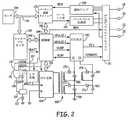
図1は、一例としての血管外心臓徐細動システム10を植え込まれている患者12の概念図である。図1に描かれている実施例では、血管外心臓徐細動システム10は、植え込み型皮下ICDシステムである。また一方、本開示の技法は、少なくとも部分的には胸骨下又は筋肉下の場所に植え込まれているリードを有する心臓徐細動システムの様な、他の血管外植え込み型心臓徐細動システムと共に利用することもできる。加えて、本開示の技法は、植え込み型ペーシングシステム、植え込み型神経刺激システム、薬物送達システム、又はリードやカテーテル又は他の構成要素が患者12内の血管外場所に植え込まれる他のシステムの様な、他の植え込み型システムと共に利用することもできる。本開示は、とはいえ、例示を目的に植え込み型血管外心臓徐細動システムの文脈で説明されている。 FIG. 1 is a conceptual diagram of a
血管外心臓徐細動システム10は、少なくとも1つの植え込み型心臓除細動リード16へ接続されている植え込み型カーディオバーター除細動器(ICD)14を含んでいる。図1のICD14は、患者12の左側部に皮下的に植え込まれている。ICD14へ接続されている除細動リード16は、ICD14から内側へ患者12の胸骨28及び剣状突起24に向かって延びている。剣状突起24付近の場所で、除細動リード16は曲がって又は向きを変え、皮下的に上方へ、実質的に胸骨28に平行に延びている。図1に描かれている実施例では、除細動リード16は、リード16が外側へ胸骨体28の左側寄りに(例えば患者12の左側部の方へ)オフセットするようにして植え込まれている。 Extravascular
除細動リード16は、除細動電極18と第2の電極(例えばICD14のハウジング又は缶25若しくは第2のリード上に設置されている電極など)の間の療法ベクトルが実質的に心臓26の心室を横切るようにして胸骨28に沿って設置されている。療法ベクトルは、1つの実施例では、除細動電極18上の或る点からICD14のハウジング又は缶25上の或る点へ延びる線として見られる。別の実施例では、除細動リード16は、除細動電極18とICD14のハウジング又は缶25(或いは他の電極)の間の療法ベクトルが実質的に心臓26の心房を横切るようにして胸骨28に沿って設置されていることもある。この場合には、血管外ICDシステム10は、心房細動を治療する療法の様な心房療法を提供するために使用されている。 The
図1に描かれている実施形態は、血管外ICDシステム10の一例としての構成であり、ここに説明されている技法を限定するものと考えられてはならない。例えば、除細動リード16は、図1の実施例では胸骨28の正中線から外側にオフセットしているとして描かれているが、当該リード16が胸骨28の右へオフセットしている又は胸骨28に亘ってより中心に位置付けられるようにして植え込まれていてもよい。加えて、除細動リード16は、それが実質的に胸骨28に平行というのではなく代わりに胸骨28から或る角度にオフセットする(例えば、近位端又は遠位端のどちらかで胸骨28から外側へ角度を付けられる)ようにして植え込まれていてもよい。別の実施例として、除細動リード16の遠位端が患者12の第2肋骨又は第3肋骨付近に位置決めされていてもよい。また一方で、除細動リード16の遠位端は、ICD14の場所、電極18、20、及び22の場所、又は他の要因に依存して、更に上方に又は更に下方に位置決めされていてもよい。 The embodiment depicted in FIG. 1 is an exemplary configuration of an
ICD14は、患者12の中腋窩線付近に植え込まれているとして描かれているが、ICD14は、同様に、患者12の他の皮下場所、例えば体幹部上の後腋窩線寄りの更に後方、体幹部上の前腋窩線寄りの更に前方、胸筋領域内、又は患者12の他の場所など、に植え込まれていてもよい。ICD14が胸筋に植え込まれる事例では、リード16は、例えば上部胸郭区域を横切って下方へ胸骨28に沿ってという具合に、異なる経路を辿ることになろう。ICD14が胸筋領域に植え込まれている場合、血管外ICDシステムは、患者の左側部に沿って延びる除細動電極を含む第2のリードを含んでいて、当該第2のリードの除細動電極がその様なICDシステムの療法ベクトルのアノード又はカソードとして機能するように患者の左側部に沿って位置付けられている。 Although the
ICD14は、密閉シールを形成してICD14内の構成要素を保護しているハウジング又は缶25を含んでいる。ICD14のハウジング25は、チタン又は他の生体適合性導電性材料の様な導電性材料又は導電性材料と非導電性材料の組合せで形成することができる。一部の事例では、ICD14のハウジング25は、療法を心臓26へ送達する又は心臓26の電気的活動を感知するのに電極18、20、又は22の1つと組み合わせて使用される電極(ハウジング電極又は缶電極と呼称される)として機能している。ICD14は、更に、電気的フィードスルーを含んでいるコネクタ組立体(時にコネクタブロック又はヘッダとも呼称される)を含んでいてもよく、当該電気的フィードスルーを通して電気的接続が除細動リード16内の導体とハウジング内に含まれる電子的構成要素の間に作られる。ハウジングは、プロセッサ、メモリ、送信器、受信器、センサ、感知回路機構、療法回路機構、及び他の適切な構成要素(ここではモジュールと呼称される場合が多い)を含む1つ又はそれ以上の構成要素を包封していてもよい。
除細動リード16は、ICD14へ接続するように構成されているコネクタを含む近位端と、1つ又はそれ以上の電極18、20、及び22を含む遠位端と、を有するリード本体を含んでいる。除細動リード16のリード本体は、シリコン、ポリウレタン、フルオロポリマー、それらの混合物、及び他の適切な材料、を含む非導電性材料から形成することができ、また1つ又はそれ以上の導体をその中に延ばす1つ又はそれ以上のルーメンを形成するように成形することができる。しかしながら技法はその様な構築に限定されない。除細動リード16は3つの電極18、20、及び22を含んでいるとして描かれているが、除細動リード16はより多い又はより少ない電極を含んでいてもよい。 The
除細動リード16は、リード本体内を除細動リード16の近位端側のコネクタから電極18、20、及び22へ延びている1つ又はそれ以上の細長い電気伝導体(描かれていない)を含んでいる。言い換えれば、除細動リード16のリード本体内に収容されている1つ又はそれ以上の細長い電気伝導体の各々は、電極18、20、又は22とそれぞれ係合することができる。除細動リード16の近位端のコネクタがICD14へ接続されると、それぞれの導体が、ICD14の療法モジュール又は感知モジュールの様な回路機構へ、関連付けられるフィードスルーを含むコネクタ組立体の接続部を介して、電気的に連結することになる。電気伝導体は、療法をICD14内の療法モジュールから電極18、20、及び22の1つ又はそれ以上へ伝送するとともに、電極18、20、及び22の1つ又はそれ以上からの感知される電気信号をICD14内の感知モジュールへ伝送する。 The
ICD14は、心臓26の電気的活動を、電極20及び22とICD14のハウジング又は缶25との組合せを含む1つ又はそれ以上の感知ベクトルを介して、感知することができる。例えば、ICD14は、電極20と電極22の間の感知ベクトルを使用して感知される電気信号を得る、電極20とICD14の導電性ハウジング又は缶25の間の感知ベクトルを使用して感知される電気信号を得る、電極22とICD14の導電性ハウジング又は缶25の間の感知ベクトルを使用して感知される電気信号を得る、又はそれらの組合せを使用して感知される電気信号を得る、ことができる。一部の事例では、ICD14は、除細動電極18と電極の1つ20又は22との間の感知ベクトル又は除細動電極18とICD14のハウジング又は缶25との間の感知ベクトルの様な、除細動電極18を含む感知ベクトルを使用して心臓の電気信号を感知している。 The
ICDは、感知される電気信号を解析して心室頻拍又は心室細動の様な頻拍を検出することができ、頻拍を検出していることに応えて電気療法を生成し心臓26へ送達することができる。例えば、ICD14は、1つ又はそれ以上の除細動ショックを、除細動リード16の除細動電極18とハウジング又は缶25を含む療法ベクトルを介して送達することができる。除細動電極18は、例えば、細長いコイル電極又は他の型式の電極であってもよい。一部の事例では、ICD14は、除細動ショックの送達に先んじて又は除細動ショックの送達後に、抗頻拍ペーシング(ATP)又はショック後ペーシングの様な1つ又はそれ以上のペーシング療法を送達することもある。これらの事例では、ICD14は、ペーシングパルスを、電極20及び22のうちの一方又は両方及び/又はハウジング又は缶25を含む療法ベクトルを介して生成し、送達している。電極20及び22は、リング電極、半球形電極、コイル電極、螺旋電極、分割電極、指向性電極、又は他の型式の電極、又はそれらの組合せ、を備えていてもよい。電極20と電極22は同じ型式の電極であってもよいし異なる型式の電極であってもよいが、図1の実施例では電極20と電極22はどちらもリング電極として描かれている。 The ICD can detect the tachycardia, such as ventricular tachycardia or ventricular fibrillation, by analyzing the sensed electrical signal, and in response to detecting the tachycardia, generate electrotherapy to the
除細動リード16は、更に、付着用形体部29をリード16の遠位端に又は遠位端寄りに含んでいてもよい。付着用形体部29は、ループ、リンク、又は他の付着用形体部であってもよい。例えば、付着用形体部29は、縫合糸によって形成されているループであってもよい。別の実施例として、付着用形体部29は、金属、被覆された金属、又はポリマーのループ、リンク、リングであってもよい。付着用形体部29は、均一又は様々に異なる厚さ及び様々に異なる寸法を有する多くの形状の何れへ形成されていてもよい。付着用形体部29は、リードへ一体化されていてもよいし、又は植え込みに先立って使用者によって付け足されてもよい。付着用形体部29は、リード16の植え込みを支援するのに及び/又はリード16を所望の植え込み場所へ固着するのに有用であろう。一部の事例では、除細動リード16は、付着用形体部に加えて又は付着用形体部に代えて、定着機構を含んでいてもよい。除細動リード16は付着用形体部29と共に描かれているが、他の実施例ではリード16は付着用形体部29を含んでいないこともある。 The
リード16は、更に、DF4コネクタ、二又コネクタ(例えばDF−1/IS−1コネクタ)、又は他の型式のコネクタの様なコネクタを、リード16の近位端に含んでいてもよい。リード16の近位端のコネクタは、ICD14のコネクタ組立体内のポートへ連結する端子ピンを含んでいてもよい。一部の事例では、リード16は、リード16の植え込みを支援する植え込み道具へ連結させることのできる付着用形体部をリード16の近位端に含んでいる場合もある。リードの近位端の付着用形体部は、コネクタから分離されていて、リードへ一体化されているか又は植え込みに先立って使用者によって付け足されるかのどちらであってもよい。
除細動リード16は、更に、リード16を剣状突起又は下部胸骨場所付近に定着させるように構成されている縫合糸スリーブ又は他の定着機構(図示せず)を電極22に近接に配置させて含んでいてもよい。定着機構(例えば縫合糸スリーブ又は他の機構)は、リードへ一体化されていてもよいし、又は植え込みに先立って使用者によって付け足されてもよい。 The
図1に描かれている実施例は、本質的に例示としてであって、この開示に説明されている技法を限定すると考えられてはならない。例えば、血管外心臓徐細動システム10は1つより多いリードを含んでいてもよい。1つの実施例では、血管外心臓徐細動システム10は、除細動リード16に加えてペーシングリードを含んでいる場合もある。 The embodiment depicted in FIG. 1 is exemplary in nature and should not be considered as limiting the techniques described in this disclosure. For example, extravascular
図1に描かれている実施例では、除細動リード16は皮下的に、例えば皮膚と肋骨又は胸骨との間に、植え込まれている。他の事例では、除細動リード16(及び/又は随意的なペーシングリード)は他の血管外場所に植え込まれている場合もある。1つの実施例では、除細動リード16は少なくとも部分的には胸骨下場所に植え込まれていることがある。その様な構成では、除細動リード16の少なくとも一部分は、胸骨の真下又は背後の縦隔内、より厳密には前縦隔内に設置されていてもよい。前縦隔は、側方を胸膜によって、後方を心膜によって、前方を胸骨28によって、境界されている。除細動リード16は、少なくとも部分的には他の心膜外場所、即ち心臓26の外表面の周りの領域内の場所に、但し心臓26の外表面と直接接触せずに、植え込まれていてもよい。これらの他の心膜外場所には、縦隔内但し胸骨28からオフセットして、上縦隔内、中縦隔内、後縦隔内、剣状突起下又は下剣状突起区域内、心尖付近、又は心臓26と直接接触せず皮下ではない他の場所、を含めることができる。更に別の実施例では、リードは心臓26の外の心膜又は心外膜の場所に植え込まれていることもある。 In the embodiment depicted in FIG. 1, the
図2は、本発明の或る実施形態による、皮下装置の密封ハウジング内の電子回路機構の例示としての配線図である。図2に描かれている様に、皮下装置14は、皮下装置14の回路機構及び当技術でよく知られている方式でペーシングエネルギーを供給するペーシング出力コンデンサへパワーを供給しているパワー供給部(図示せず)へ連結されている低電圧バッテリ153を含んでいる。低電圧バッテリ153は、例えば、1つ又は2つの従来型のLiCFXセル、LiMnO2セル、又はLil2セルで形成することができる。皮下装置14は、更に、1つ又は2つの従来型のLiSVOセル又はLiMnO2セルで形成されていてもよいとされる高電圧バッテリ112を含んでいる。本発明の或る実施形態により、図2には低電圧バッテリと高電圧バッテリの2つともが示されているが、装置14は単一のバッテリを高電圧使用と低電圧使用を兼ねて利用しているということもあり得る。FIG. 2 is an exemplary wiring diagram of the electronics in a sealed housing of a subcutaneous device, according to an embodiment of the present invention. As depicted in FIG. 2, the
更に図2を参照して、皮下装置14の諸機能は、ソフトウェア、ファームウェア、及びハードウェアを用いて制御されていて、それらが協働的にECG信号を監視し、カーディオバージョン−除細動ショック又はペーシングが必要である場合を判定し、処方されるカーディオバージョン−除細動療法及びペーシング療法を送達させる。皮下装置14は、本願の譲受人に譲渡されたケイメル(Keimel)への米国特許第5,163,427号「単数及び複数のカーディオバージョン及び除細動パルスを送達するための機器」及びケイメルへの米国特許第5,188,105号「頻脈性不整脈を治療するための機器及び方法」に示されている、単相性、同時二相性、及び順次二相性のカーディオバージョン−除細動ショックを選択的に送達するための回路機構であって、典型的には、高電圧出力回路140のコモン出力123へ連結されているICD IPGハウジング電極28と、後方に皮下的に配置されていて高電圧出力回路140のHVI出力113へ連結されているカーディオバージョン−除細動電極24と、を採用している回路機構、を組み入れていてもよい。 Still referring to FIG. 2, the functions of the
カーディオバージョン−除細動ショックエネルギー及びコンデンサ充電電圧は、心臓と接触にある少なくとも1つのカーディオバージョン−除細動電極を有するICD及び皮膚と接触にあるカーディオバージョン−除細動電極を有する殆どのAEDによって供給される電圧に対し中間的とすることができる。殆どの二相性波形を使用しているICDにとって必要な典型的最大電圧は大凡750ボルトであって関連付けられる最大エネルギー大凡40ジュールとなる。AEDにとって必要な典型的最大電圧は、使用されるモデル及び波形にも依存するが、大凡2000−5000ボルトであって関連付けられる最大エネルギー大凡200−360ジュールとなる。本発明の皮下装置14は、約300乃至大凡1500ボルトの範囲の最大電圧を使用していて、大凡25乃至150ジュール又はそれ以上のエネルギーと関連付けられている。総高電圧静電容量は、約50乃至約300マイクロファラッドの範囲となり得る。その様なカーディオバージョン−除細動ショックは、悪性の頻脈性不整脈時のみ、例えば心室細動が本明細書の以下に説明されている検出アルゴリズムを採用しているファーフィールド心臓ECGの処理を通じて検出されたときにのみ送達される。 Cardioversion-defibrillation shock energy and capacitor charging voltage are reduced by at least one cardioversion-ICD with defibrillation electrodes in contact with the heart and most AEDs with cardioversion-defibrillation electrodes in contact with the skin May be intermediate to the voltage supplied by A typical maximum voltage required for an ICD using most biphasic waveforms is approximately 750 volts, with an associated maximum energy of approximately 40 joules. The typical maximum voltage required for an AED is approximately 2000-5000 volts, with an associated maximum energy of approximately 200-360 Joules, depending on the model and waveform used. The
図2では、感知アンプ190が、ペーサー/装置タイミング回路178と合同で、皮下電極18、20、22及び装置14の缶又はハウジング25の選択された対によって定義される特定のECG感知ベクトルを横断して発現するファーフィールドECG感知信号を、又は随意であるが仮想信号(即ち2つのベクトルの数学的組合せ)が選択されている場合には当該仮想信号を、処理する。例えば、装置は、リー(Lee)らへの米国特許第6,505,067号「仮想ECG又はEGM信号を導出するためのシステム及び方法」に記載されている仮想ベクトル信号を生成するようになっていてもよく、両特許をここに参考文献としてそっくりそのまま援用する。加えて、ベクトル選択は、患者の医師によって選択されテレメトリリンク経由でプログラマからプログラムされるようになっていてもよい。 In FIG. 2,
感知電極対の選択は、スイッチマトリクス/MUX191を通じて関心対象のECG信号の最も信頼できる感知を提供する方式でなされており、関心対象のECG信号とは突然死に繋がる心室細動の危険性があると確信されている患者にとってはR波ということになる。ファーフィールドECG信号は、スイッチマトリクス/MUX191を通じて感知増幅器190の入力へ渡され、当該感知増幅器190がペーサー/装置タイミング回路178と合同で、感知されるEGMを評価する。除脈、即ちアジストリーは、ペーサータイミング回路178及び/又は制御回路144内の補充収縮間隔タイマーによって判定されるのが典型的である。連続するR波間の間隔が補充収縮間隔を超過すれば、ペーストリガ信号がペーシング刺激を生成するペーシングパルス生成器192へ印加される。除脈ペーシングは、カーディオバージョン−除細動ショックの送達後に心臓出力を維持するために大抵は一時的に提供されるものであって、心臓が正常機能へ回復してゆく際に心臓をゆっくりと拍動させることができる。ノイズ存在下での皮下ファーフィールド信号の感知は、リーらへの米国特許第6,236,882号「ECGを監視するためのノイズ除去」に記載されている適切な拒否的及び拡張可能な適応期間の使用によって支援されてもよく、同特許をここに参考文献としてそっくりそのまま援用する。 The selection of the sensing electrode pairs is done in a manner that provides the most reliable sensing of the ECG signal of interest through the switch matrix /
悪性の頻脈性不整脈の検出は、制御回路144内で、ペーサー/装置タイミング回路178と感知増幅器回路190からタイミング及び制御回路144へ出力されるR波感知事象信号間の間隔の関数として判定される。本発明は、間隔ベースの信号解析方法のみならず、本明細書で以下に説明されている様に補助的なセンサ及び形態学処理の方法及び機器も利用していることに注目されたい。 The detection of a malignant tachyarrhythmia is determined in the
組織色、組織酸素化、呼吸、患者活動、及び同種のもの、の様な補助的なセンサを使用して、除細動療法を適用するか又は差し控えるかの決定に寄与させることができるということは、オルト(Alt)への米国特許第5,464,434号「突発的血流力学的変化に応答性の医療介入装置」に全体的に記載されており、同特許をここに参考文献としてそっくりそのまま援用する。センサ処理ブロック194がセンサデータをマイクロプロセッサ142へデータバス146経由で提供する。具体的には、患者の活動及び/又は姿勢は、シェルドン(Sheldon)への米国特許第5,593,431号「患者の活動及び姿勢感知のための複数のDC加速度計を採用している医療業務及び方法」に記載されている機器及び方法によって判定することができ、同特許をここに参考文献としてそっくりそのまま援用する。患者呼吸は、プリッチ(Plicchi)らへの米国特許第4,567,892号「植え込み型心臓ペースメーカー」に記載されている機器及び方法によって判定することができ、同特許をここに参考文献としてそっくりそのまま援用する。患者の組織酸素化又は組織色は、エリックソン(Erickson)らへの米国特許第5,176,137号に記載されているセンサ機器及び方法によって判定することができ、同特許をここに参考文献としてそっくりそのまま援用する。’137号特許の酸素センサは、皮下装置ポケットに位置付けられていてもよいし、又は代わりに、接触若しくはほぼ接触にある組織の酸素化又は色の感知を可能にするべくリード18上に位置付けられていてもよい。 Auxiliary sensors such as tissue color, tissue oxygenation, respiration, patient activity, and the like can be used to contribute to the decision to apply or withhold defibrillation therapy. This is fully described in US Patent No. 5,464,434 to Alt, "Medical Intervention Device Responsive to Sudden Hemodynamic Changes," which is incorporated herein by reference. Intact as it is.
検出アルゴリズム判定基準の遂行における特定の諸段階は、マイクロプロセッサ、RAM及びROM、関連付けられる回路機構、及びRAMの中へ当技術の従来式のテレメトリインターフェース(図示せず)を介してプログラムされていてもよいとされる記憶された検出判定基準を含むマイクロコンピュータ142内で協働的に遂行される。データ及びコマンドが、マイクロコンピュータ142と、タイミング及び制御回路144、ペーサータイミング/増幅器回路178、及び高電圧出力回路140との間で、双方向データ/制御バス146経由でやり取りされる。ペーサータイミング/増幅器回路178及び制御回路144は、遅いクロック速度でクロックされる。マイクロコンピュータ142は通常はスリープ状態であるが、各R波感知事象によって発現する割り込み、又はダウンリンクテレメトリプログラミング命令が受信されると発現する割り込み、又は心臓ペーシングパルスの送達があり次第発現する割り込み、によって呼び覚まされ速いクロックで動作させられて、何れかの必要な数学的計算を遂行する、頻拍及び細動の検出手続きを遂行する、及びペーサー/装置タイミング回路機構178内のタイマーによって監視され制御される時間間隔を更新する。 The specific steps in performing the detection algorithm criteria are programmed into the microprocessor, RAM and ROM, associated circuitry, and RAM via a conventional telemetry interface (not shown) in the art. It is performed cooperatively in
悪性の頻拍が検出されると、高電圧コンデンサ156、158、160、及び162が高電圧充電回路164によって事前にプログラムされている電圧レベルへ充電される。一般的に高電圧出力コンデンサ156、158、160、162上に定電荷を維持するのは非効率であると考えられている。代わりに、充電は、制御回路144がライン145上を高電圧充電回路164へ送達される高電圧充電コマンドHVCHGを発令して開始され、充電は双方向制御/データバス166及びHV出力回路140からのフィードバック信号VCAPを用いて制御される。高電圧出力コンデンサ156、158、160、及び162は、フィルム、アルミニウム電解、又は湿式タンタルによる構築であってもよい。 When a malignant tachycardia is detected, the
高電圧バッテリ112の負端子は系統接地へ直接連結されている。スイッチ回路114は通常は開いているので、高電圧バッテリ112の正端子は高電圧充電回路164の正パワー入力から接続を切られている。高電圧充電コマンドHVCHGは、更に、導体149を介してスイッチ回路114の制御入力へ伝導され、スイッチ回路114はそれに応えて閉じて正の高電圧バッテリ電圧EXT B+を高電圧充電回路164の正のパワー入力へ接続する。スイッチ回路114は、例えば、そのソース−ドレイン経路がEXT B+導体118を中断していてそのゲートが導体145上のHVCHG信号を受信している電界効果トランジスタ(FET)であってもよい。高電圧充電回路164は、それにより、高電圧出力コンデンサ156、158、160、及び162を高電圧バッテリ112からの充電電流で充電する段階を始める準備のできた状態にされる。 The negative terminal of
高電圧出力コンデンサ156、158、160、及び162は、非常に高い電圧、例えば300−1500Vへ充電されて、皮下カーディオバージョン−除細動電極113と123の電極対間の身体及び心臓を通して放電されるようになっていてもよい。電圧充電回路機構の詳細事項もまた本発明の実践に関して決定的であるとは見なされていないが、発明の目的に適していると確信される1つの高電圧充電回路が開示されている。高電圧コンデンサ156、158、160、及び162は、例えば本願の譲受人に譲渡されたウィールダーズ(Wielders)らへの米国特許第4,548,209号「植え込み型カーディオバーターのためのエネルギー変換器」に詳細に記載されている高電圧充電回路164及び高周波数高電圧変成器168によって充電することができる。適正な充電極性が、高電圧変成器168の出力巻線とコンデンサ156、158、160、及び162を相互接続するダイオード170、172、174、及び176によって維持される。以上に指摘されている様に、コンデンサ充電の状態は、高電圧出力回路140内の回路機構によって監視されていて、当該回路機構が電圧を指し示すフィードバック信号であるVCAPをタイミング及び制御回路144へ提供する。タイミング及び制御回路144は、VCAP信号がプログラムされているコンデンサ出力電圧、即ちカーディオバージョン−除細動ピークショック電圧に一致したとき、高電圧充電コマンドHVCHGを終結させる。 The high
制御回路144は、次いで、カーディオバージョン用又は除細動用のショックの送達をトリガするための高電圧出力回路140へ印加される第1及び第2の制御信号であるNPULSE1及びNPULSE2それぞれを発現させる。特に、NPULSE1信号は、コンデンサ156及び158を備える第1のコンデンサバンクの放電をトリガする。NPULSE2信号は、第1のコンデンサバンクとコンデンサ160及び162を備える第2のコンデンサバンクの放電をトリガする。単にNPULSE1信号及びNPULSE2信号のアサーションの数及び時間順を修正しさえすれば、複数の出力パルスレジーム間で選択することが実施可能である。NPULSE1信号及びNPULSE2信号は、順次に、同時に、又は個別に、提供することができる。このやり方で、制御回路機構144は、図2に示されている様に、高エネルギーカーディオバージョン−除細動ショックをHV−1及びCOMMON出力へ連結されている一対のカーディオバージョン−除細動電極18と25の間に送達する高電圧出力段140の動作を制御する働きをする。 The
而して、皮下装置14は、患者の心臓の状態を監視し、要カーディオバージョン−除細動頻脈性不整脈の検出に応えて、カーディオバージョン−除細動電極18及び25を通じてのカーディオバージョン−除細動ショックの送達を開始する。高HVCHG信号は、高電圧バッテリ112にスイッチ回路114を通じて高電圧充電回路164と接続させ、出力コンデンサ156、158、160、及び162の充電を始めさせる。充電は、プログラムされている充電電圧がVCAP信号によって反映されるまで続き、反映された時点で制御及びタイミング回路144はHVCHG信号を低く設定して充電を終結させ、スイッチ回路114を開く。皮下装置14は、以上に説明されている方式での心臓へのカーディオバージョンショックを検出されるR波と時間的に同期させて送達しようと試みるようにプログラムすることもできるし、又は以上に説明されている方式での心臓へのカーディオバージョンショックを検出されるR波に対し送達を同期させるよう試みること無しに送達するようにプログラムする又は製作することもできる。頻脈性不整脈の検出及びカーディオバージョン−除細動ショックの送達に関係付けられるエピソードデータは、患者の心臓の状態の診断を容易にするための当技術でよく知られている外部プログラマへのアップリンクテレメトリ送信に備えてRAMに記憶させることができる。予防的理由から装置14を受け入れている患者は、患者の病態の更なる評価及びより高度なICD植え込みの必要性の評定のために、1つ1つのその様なエピソードを担当医師へ報告するように指示されることになろう。 Thus, the
皮下装置14は、テレメトリ回路(図2には示されていない)を含んでいるのが望ましく、そうすれば当該装置を外部プログラマ20によって2方向テレメトリリンク(図示せず)を介してプログラムさせることが可能である。アップリンクテレメトリは、装置状態及び診断/事象データが患者の医師によるレビューのために外部プログラマ20へ送られることを可能にさせる。ダウンリンクテレメトリは、外部プログラマが医師の制御を介して、装置機能のプログラミング及び特定の患者についての検出及び療法の最適化を行えるようにする。本発明の実践での使用に適したプログラマ及びテレメトリシステムは何年も前からよく知られている。プログラマが植え込まれた装置によって受信されるべき制御コマンド及び動作パラメータ値を送信することができるように、そして植え込まれた装置が診断データ及び動作データをプログラマへ通信することができるように、既知のプログラマは植え込まれた装置相手に双方向無線周波数テレメトリリンクを介して通信しているのが典型的である。本発明を実践するという目的に適していると確信されるプログラマは、ミネソタ州ミネアポリスのメドトロニック・インク(Medtronic, Inc.)社から商業的に入手できるモデル9790及びCareLink(登録商標)のプログラマを含む。 The
外部プログラミングユニットと植え込まれた装置との間の必要な通信チャネルを提供するための様々なテレメトリシステムが開発されており、当技術ではよく知られている。本発明を実践するという目的に適していると確信されるテレメトリシステムは、例えば、以下の米国特許、即ち、ウィボーニー(Wyborny)らへの「植え込まれた医療装置のためのテレメトリフォーマット」と題された米国特許第5,127,404号、マルコウィッツ(Markowitz)への「医療装置のためのマーカーチャネルテレメトリシステム」と題された米国特許第4,374,382号、トンプソン(Thompson)らへの「医療装置のためのテレメトリシステム」と題された米国特許第4,556,063号、に開示されている。ウィボーニーらの’404号、マルコウィッツの’382号、及びトンプソンらの’063号は、本発明の譲受人に譲渡されており、各々をこれにより参考文献としてここにそれぞれそっくりそのまま援用する。 Various telemetry systems have been developed to provide the necessary communication channels between the external programming unit and the implanted device and are well known in the art. Telemetry systems believed to be suitable for the purpose of practicing the present invention are described, for example, in the following U.S. patents entitled "Telemetry Format for Implanted Medical Devices" to Wyborny et al. U.S. Pat. No. 5,127,404 issued to Markowitz, U.S. Pat. No. 4,374,382 entitled "Marker Channel Telemetry System for Medical Devices," Thompson et al. No. 4,556,063, entitled "Telemetry System for Medical Devices". No. 404, Markowitz et al., '382, and Thompson et al.,' 063, are assigned to the assignee of the present invention and each is hereby incorporated herein by reference in its entirety.
本発明の或る実施形態によれば、好適なECGベクトルセットを自動的に選択するためには、信号の品質を格付けする拠り所となるメリットの指標を有することが必要である。「品質」は、精度の高い心拍数推定及び患者の通常の洞調律と患者の心室性頻脈性不整脈の間の精度の高い形態学的波形分離を提供する信号の能力と定義される。 According to some embodiments of the present invention, to automatically select a suitable set of ECG vectors, it is necessary to have an indicator of the merit on which to rank the signal quality. "Quality" is defined as the ability of the signal to provide accurate heart rate estimation and accurate morphological waveform separation between the patient's normal sinus rhythm and the patient's ventricular tachyarrhythmia.
適切な指標は、R波振幅、R波ピーク振幅対R波間波形振幅(即ち信号対ノイズ比)、低勾配含量(low slope content)、相対的な高対低周波数パワー、平均周波数推定、確率密度関数、又はこれらのメトリックの何らかの組合せ、を含んでいてもよい。 Suitable indicators are R-wave amplitude, R-wave peak amplitude versus R-wave waveform amplitude (ie, signal-to-noise ratio), low slope content, relative high-to-low frequency power, average frequency estimation, probability density. It may include a function, or some combination of these metrics.
自動ベクトル選択は、植え込み時に果たされてもよいだろうし、又は定期的に(毎日、毎週、毎月)果たされてもよいだろうし、或いはその両方であってもよいだろう。植え込み時なら、自動ベクトル選択は、リードインピーダンス及びバッテリ電圧を測定するといった様な活動を遂行する自動装置ターンオン手続きの一部として開始されてもよい。装置ターンオン手続きは、植え込み医師によって(例えばプログラマボタンを押すことによって)開始させるようになっていてもよいし、代わりに、装置/リード植え込みの自動検出があり次第自動的に開始されるようになっていてもよい。皮下装置14の装置をその場に縫い付け切開を閉じるのに先立って、ターンオン手続きが、更に、自動ベクトル選択確定基準を使用し、ECGベクトルの品質が現在の患者にとって、また装置及びリード位置にとって、適切であるかどうかを判定するようになっていてもよい。その様なECG品質表示があれば、植え込み医師はECG信号の品質を必要に応じて改善するべく装置を新しい場所又は新しい向きへ操縦できるようになるはずである。更に、装置ターンオン手続きの一部として植え込み時に好適な単数又は複数のECGベクトルが選択されるようになっていてもよい。好適なベクトルは、格付け推定及び検出精度を最大化する指標を有するベクトルであってもよいだろう。更に、医師によって好適とされるベクトルの演繹的なセットが存在していて、それらのベクトルが或る最小閾値を超えている限り、又はそれらのベクトルが幾つかの他のより望ましいベクトルより極わずかしか悪くない限り、演繹的に好適なベクトルが選定される、というようになっていてもよい。特定のベクトルがほぼ同一と考えられることもあり、それらは、演繹的に選択されたベクトル指標が或る既定の閾値を下回らない限り検定されない。 Automatic vector selection may be performed at the time of implantation, or may be performed periodically (daily, weekly, monthly), or both. At the time of implantation, automatic vector selection may be initiated as part of an automatic device turn-on procedure that performs activities such as measuring lead impedance and battery voltage. The device turn-on procedure may be initiated by the implant physician (eg, by pressing a programmer button), or alternatively, may be automatically initiated upon automatic detection of device / lead implantation. May be. Prior to sewing the device of the
装置のメトリックパワー消費量及びパワー所要量にも依るが、ECG信号品質メトリックは、所望されるだけ頻繁にベクトルの範囲(又は代わりにサブセット)に基づいて測定されていてもよい。データは、例えば、分単位、時間単位、日単位、週単位、又は月単位で収集されてもよい。更に頻繁な(例えば分毎の)測定値を時間に亘って平均し、それを使用し、例えば、一時的に発生するノイズ、運動ノイズ、又はEMIに対するベクトルの影響の被り易さに基づいて、ベクトルを選択するようにしてもよい。 Depending on the metric power consumption and power requirements of the device, the ECG signal quality metric may be measured based on the vector range (or alternatively a subset) as often as desired. Data may be collected, for example, on a minute, hour, day, week, or month basis. More frequent (eg, minute-by-minute) measurements are averaged over time and used, for example, based on susceptibility to transient noise, motion noise, or vector effects on EMI. A vector may be selected.
代わりに、皮下装置14は、患者活動の表示器/センサ(ピエゾ抵抗型、加速度計、インピーダンス、又は同種物)を有していて、中又は高患者活動期間中の自動ベクトル測定を最小又は無活動期間中の自動ベクトル測定に対し遅延させるようにしてもよい。1つの代表的なシナリオは、ECGベクトルを、毎日1回又は毎週1回、(内部クロック(例えば午前2時)を使用して)患者が眠っていると判定されたか又は(2軸又は3軸加速度計を介して)患者の位置を及び活動の欠如を確定することによって眠っていると推論されている間に、検定/評価することを含んでいてもよい。別の考えられるシナリオでは、ECGベクトルを検定/評価する段階は、毎日1回又は毎週1回、患者が体操していると知られている間に遂行されるようになっていてもよい。 Alternatively, the
低頻度の、自動的、定期的な測定がなされる場合もやはり、信号内のノイズ(例えば、筋肉、運動、EMI、など)を測定し、ノイズが鎮まってしまう時間期間までベクトル選択測定を延期する、というようにするのが望ましい。 Even when infrequent, automatic, periodic measurements are taken, the noise in the signal (eg, muscle, exercise, EMI, etc.) is measured and the vector selection measurement is performed until the noise subsides. It is desirable to postpone it.
皮下装置14は、随意的には、(2軸又は3軸加速度計を介しての)患者の姿勢の表示を有していてもよい。このセンサは、ECG品質の差が単純に姿勢/位置変化の結果ではないことを確実にするのに使用することができる。センサを使用し、多数の姿勢でのデータを収集し、ECG品質がこれらの姿勢に亘って平均されるようになっていてもよいし、又はそれ以外に組み合わされるか、又は代わりに好適な姿勢について選択されるようになっていてもよい。 The
1つの実施形態では、ベクトル品質メトリック計算が、プログラマを使用する臨床医によって、植え込み時か又はその後の来院時の設定中かの何れかに遂行されるか、又は装置及びプログラマとの遠隔リンクを介して遠隔的に遂行されるようになっている。別の実施形態によれば、ベクトル品質メトリック計算は、各利用可能な感知ベクトルについて、毎日複数回、毎日1回、毎週1回、又は月単位で、の様な既定の回数だけ装置によって自動的に遂行されるようになっている。加えて、それら値が各ベクトルについて例えば1週間の経過に亘って平均されてもよいであろう。平均化は、時間加重及びメモリ考慮事項に依存して、移動平均又は反復平均から成っていてもよい。 In one embodiment, the vector quality metric calculation is performed by the clinician using the programmer, either at the time of implantation or during a subsequent visit setting, or by establishing a remote link with the device and programmer. To be performed remotely. According to another embodiment, the vector quality metric calculation is automatically performed by the device a predetermined number of times for each available sensing vector, such as multiple times daily, once daily, weekly, or monthly. Is to be carried out. In addition, the values could be averaged over the course of, for example, one week for each vector. The averaging may consist of a moving average or an iterative average, depending on time weighting and memory considerations.
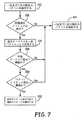
図3は、1つの実施形態による、医療装置での感知ベクトルを選択するための方法の流れ図である。図3に示されている様に、本開示の或る実施形態によれば、装置は、利用可能な感知ベクトル102−106毎に心臓信号を、例えばここに参考文献としてその全体が援用されている米国特許出願第14/250,040号に記載されている様な当技術で既知の感知技法を使用して感知する。装置は、利用可能な感知ベクトル102−106毎に心臓信号の感知されるR波を入手し、ブロック124、そして以下に説明されている様に、当該感知ベクトル102−106についての感知されているR波と関連付けられる、ベクトルの感知の品質を判定するためのベクトル品質メトリックを確定し、ブロック126、且つ形態解析の品質を判定するための形態品質メトリックを確定する、ブロック128。感知されているR波と関連付けられる、ブロック126でのベクトル品質メトリック及びブロック128での形態メトリックが、各感知ベクトル102−106について確定されたら、装置は、ベクトル品質メトリック及び形態メトリックが、感知ベクトル102−106の各々につき既定閾値数の心臓周期について確定されてしまったかどうかを判定する、ブロック130。ベクトル品質メトリック及び形態メトリックが、各感知ベクトル102−106につき既定閾値数の心臓周期について確定されていなければ、即ちブロック130でNoの場合、装置は、各感知ベクトル102−106について次のR波124を入手し、感知ベクトル102−106の各々につき次の感知される心臓周期についてプロセスが繰り返される。1つの実施形態によれば、ベクトル品質メトリック及び形態メトリックは例えば15の心臓周期について確定される。 FIG. 3 is a flowchart of a method for selecting a sensing vector at a medical device, according to one embodiment. As shown in FIG. 3, according to an embodiment of the present disclosure, the device may include a cardiac signal for each available sensing vector 102-106, e.g., incorporated herein by reference in its entirety. Sensing using sensing techniques known in the art, such as described in US patent application Ser. No. 14 / 250,040. The device obtains a sensed R-wave of the cardiac signal for each available sense vector 102-106, block 124, and sensed for that sense vector 102-106, as described below. Determining a vector quality metric associated with the R-wave to determine the quality of sensing the vector, block 126, and determining a morphological quality metric to determine the quality of the morphological analysis, block 128. Once the vector quality metric at
ベクトルメトリック及び形態メトリックが、各感知ベクトル102−106につき既定閾値数の心臓周期について確定されていれば、即ちブロック130でYesの場合、装置は、以下に説明されている様に、確定されたベクトル品質メトリック及び形態メトリックを使用して選択メトリックを確定し、ブロック132、以降の感知及び装置による不整脈検出中に利用されるべき1つ又はそれ以上のベクトルを確定された選択メトリックに基づいて選択する、ブロック134。感知ベクトル102−106の更新の合間に起こるようにプログラムされている時間の量、即ち一例として時間数、日数、週数、又は月数に依存して、装置は次の予定されるベクトル選択確定まで待ち、ブロック136、当該時点でベクトル選択プロセスが繰り返される。 If the vector metric and the morphology metric have been determined for a predetermined threshold number of cardiac cycles for each sensing vector 102-106, i.e., Yes at
図4は、1つの実施形態による、医療装置での感知ベクトルの選択中に複数の感知ベクトルに沿って感知されている心臓信号のグラフ表示である。図4に描かれている様に、ベクトル選択プロセス中に、装置は、利用可能な感知ベクトル102−106毎に心臓信号100を、例えばここに参考文献としてその全体が援用されている米国特許出願第14/250,040号の様な当技術で既知の感知技法を使用して感知する。例えば図4に描かれている様に1つの実施形態によれば、装置は、ハウジング又は缶25と電極22の間を延びる水平の感知ベクトル102、ハウジング又は缶25と電極20の間を延びる斜めの感知ベクトル104、及び電極20と電極22の間を延びる垂直の感知ベクトル106、を含む利用可能な感知ベクトルの各々からのECG信号100を感知する。装置は、各感知ベクトル102−106について、感知される信号が時間依存自律調節式感知閾値110を超えている場合に、感知されるR波108が起こっているとして判定する。 FIG. 4 is a graphical representation of a cardiac signal being sensed along a plurality of sensing vectors during selection of a sensing vector at a medical device, according to one embodiment. As depicted in FIG. 4, during the vector selection process, the device converts the
R波108が感知されると、装置は、感知されるR波についてのベクトル品質メトリック及び形態メトリックを確定する、図3のブロック126及びブロック128。図4に描かれている様に、図3のブロック126でベクトル品質メトリックを確定するために、例えば、装置は、感知ベクトル102−106と関連付けられるベクトル品質メトリック確定用のベクトル品質メトリック検出ウィンドー112を、感知ベクトル102−106の各々についての感知されるR波108に基づいて設定する。或る実施形態によれば、装置は、R波108から既定距離116に位置する始点114にて開始する品質メトリック検出ウィンドー112を、信号100の解析を感知されるR波108と関連付けられるQRS信号のT波が起こる可能性のある信号100の予想される範囲内に遂行できるようにする検出ウィンドー幅118を持たせて設定する。例えば、装置は、品質メトリック検出ウィンドー112を、大凡200msの幅118を有していて、品質メトリック検出ウィンドー112の始点114が感知されるR波108から大凡150−180ミリ秒の間に位置付けられていて、幅118が検出ウィンドー始点114から検出ウィンドー終点120へ即ち検出されるR波108から大凡350−380msの距離にある終点120まで200ms延びているものとして設定している。品質メトリック検出ウィンドー112が設定されたら、装置は、品質メトリック検出ウィンドー112内の感知される信号100と感知閾値110の間の最小信号差分122、即ち感知される信号100と感知閾値110の間を延びる最小距離、を確定する。3つの感知ベクトル102−106の各々についてのこの確定された最小信号差分122は、次いで、それら感知ベクトルでの同時に感知されるR波108についてのベクトル品質メトリックとして設定される、ブロック126。 When the R-
図5は、1つの実施形態による、感知ベクトルを選択するために形態メトリックを確定するための或る方法の流れ図である。図3のブロック126での形態メトリックを確定するために、装置はR波108について狭パルス計数即ちパルス数を確定する。例えば、感知ベクトル102−106と関連付けられる各R波108についての狭パルス計数を確定するために、装置はR波と関連付けられる個別パルスを、例えば本願の譲受人に譲渡された、ここに参考文献としてその全体が援用されている米国特許出願第13/826,097号及び同第14/255,158号に記載されている様な既知の技法を使用して確定する。識別されたパルスそれぞれについて、装置はパルスの幅が既定閾値より小さいかどうかを判定する。具体的には、図5に示されている様に、装置は、R波と関連付けられる識別されているパルスの単一パルスを入手し、ブロック200、当該パルスと関連付けられるパルス幅を確定し、ブロック202、そしてパルス幅がパルス幅閾値より小さい又はパルス幅閾値に等しいかどうかを判定する、ブロック204。 FIG. 5 is a flowchart of a method for determining a morphology metric to select a sensing vector, according to one embodiment. To determine the morphology metric at
個別パルスのパルス幅がパルス幅閾値より小さい又はパルス幅閾値に等しいかどうかを判定する段階であるブロック204でのYesに加え、装置は、更に、パルスの絶対振幅が振幅閾値より大きいかどうかを判定するようになっていてもよい、ブロック206。或る実施形態によれば、パルス幅閾値は例えば23ミリ秒として設定されていてもよく、振幅閾値は、本願の譲受人に譲渡された、ここに参考文献としてその全体が援用されている米国特許出願第13/826,097号及び同第14/255,158号に記載の拍動とテンプレートの整列時の勾配閾値が充たされたかどうかの判定に使用されている最大勾配の或る割合、例えば8分の1など、として設定されている。 In addition to Yes at
パルス幅判定であるブロック204が振幅閾値判定であるブロック206より先に起こるものとして描かれているが、ブロック204とブロック206の判定は何れの順序で遂行されてもよいと理解している。従って、個別パルスのパルス幅がパルス幅閾値より小さくもパルス幅閾値に等しくもなく即ちブロック204でのNoか、パルスの絶対振幅が振幅閾値より大きくない即ちブロック206でのNo、のどちらかであれば、当該パルスは狭パルス計数に含まれるべきでないと判定される。装置は、パルス数が狭パルス計数パラメータを満たしているかどうかの判定がR波拍動の識別されているパルス全てについてなされてしまったかどうかを判定することに進む、ブロック210。判定が、識別されているパルス全てについてなされていなければ、即ちブロック210でNoの場合、装置は、R波と関連付けられる次のパルスを識別し、ブロック200、そして拍動についての狭パルス計数を確定するプロセス即ちブロック202-ブロック208が次のパルスについて繰り返される。 Although
個別パルスのパルス幅がパルス幅閾値より小さい又はパルス幅閾値に等しい即ちブロック204でYes且つパルスの絶対振幅が振幅閾値より大きい即ちブロック206でYesであれば、パルス数は個別R波についての幅閾値と振幅閾値を満たしているということであり、狭パルス計数は1増加される、ブロック208。 If the pulse width of the individual pulse is less than or equal to the pulse width threshold, ie, Yes in
判定がR波と関連付けられる識別されているパルス全てについてなされてしまったら、即ちブロック210でYesの場合、装置は、R波についての狭パルス計数をブロック208での結果として更新された狭パルス計数に等しく設定する、ブロック212。このやり方では、R波についての狭パルス計数は、R波についての識別されているパルスのうち幅閾値と振幅閾値の両方を満たしているパルスの総数、つまり23ミリ秒より小さいパルス幅を有し尚且つ例えば拍動とテンプレートとの整列時に使用されている最大勾配の8分の1より大きい絶対振幅を有しているパルスの総数である。ブロック212からの最終的な狭パルス計数は、次いで、各R波についての形態メトリックとして記憶される。 If a determination has been made for all of the identified pulses associated with the R-wave, ie, Yes in
このやり方では、感知ベクトル102−106の各々に沿って感知される複数のR波についてプロセスが繰り返され、その結果、ベクトル品質メトリックと形態メトリックの両方が感知ベクトル102−106それぞれにつき既定閾値数の心臓周期例えば一例として15の心臓周期について確定されてしまったら、即ちブロック130の後、装置は、形態選択メトリックを確定し、ベクトル選択メトリックを暫定的に得る、図3のブロック132。図3及び図4に示されている様に、既定閾値数の心臓周期全てについて最小信号差分122が確定されてしまったら、即ちブロック130でYesの場合、装置は、各ベクトル102−106についてのベクトル選択メトリックを、当該感知ベクトルについて確定されている15の最小信号差分122に基づいて暫定的に得る。例えば、或る実施形態によれば、装置は、各感知ベクトルについての15の最小信号差分122の中央値を確定し、当該感知ベクトルについてのベクトル選択メトリックを、暫定的に関連付けられる最小信号差分122の確定された中央値に等しく設定する。感知ベクトル102−106の各々に1つずつベクトル選択メトリックが暫定的に設定されたら、装置は感知ベクトル102−106についてのそれらベクトル選択メトリックを順位付ける。例えば、装置は暫定的に設定されたベクトル選択メトリックを一番上から一番下まで順位付け、その結果、図4の実施例では、斜めの感知ベクトル104は、当該ベクトルについての中央値最小信号差分が0.84ミリボルトであったことから一位に順位付けられ、水平の感知ベクトル102は、当該ベクトルについての中央値最小信号差分が0.82ミリボルトであるので二位に順位付けられ、垂直の感知ベクトル106は、当該感知ベクトルについての中央値最小信号差分が0.55ミリボルトであるので最下位に順位付けられることになる。In this manner, the process is repeated for multiple R-waves sensed along each of the sensing vectors 102-106, such that both the vector quality metric and the morphology metric are equal to a predetermined threshold number of sensing vectors 102-106, respectively. If it is determined for cardiac cycle 15 as the cardiac cycle eg an example, i.e. after
同様に、図3のブロック132で形態選択メトリックを確定するために、装置は、感知ベクトル102−106の各々についての15の確定された狭パルス計数の平均値、中央値、又は最大パルス計数を確定することができる。感知ベクトル102−106に沿って同時に感知されているR波についての確定された平均値、中央値、又は最大狭パルス計数に基づき、装置はそれらベクトルを確定された形態選択メトリックに基づいて低パルス計数、中パルス計数、及び高パルス計数の1つとして順位付ける。例えば、1つの実施形態によれば、感知ベクトルと関連付けられる平均値、中央値、又は最大パルス計数が5より大きければ、当該ベクトルについての最終的なパルス計数即ち形態選択メトリックは「高」であると判定される。感知ベクトルと関連付けられる平均値、中央値、又は最大パルス計数が5以下但し2以上であれば、当該ベクトルについての最終的なパルス計数即ち形態選択メトリックは「中」であると判定される。そうではなく、感知ベクトルと関連付けられる平均値、中央値、又は最大パルス計数が1より小さい又は1に等しければ、当該ベクトルについての最終的なパルス計数即ち形態選択メトリックは「低」であると判定される。 Similarly, to determine the morphology selection metric at
別の実施形態によれば、感知ベクトル102−106は、形態選択メトリックに基づいて相対的に順位付けられてもよく、そうすると、最も大きいパルス計数を有する感知ベクトルが「高」、2番目に大きいパルス計数を有する感知ベクトルが「中」、そして最も低いパルス計数を有する感知ベクトルが「低」として識別されることになろう。 According to another embodiment, the sensing vectors 102-106 may be ranked relatively based on the morphology selection metric, so that the sensing vector with the largest pulse count is "high" and the second largest. The sense vector with the pulse count will be identified as "medium" and the sense vector with the lowest pulse count will be identified as "low".
図6は、或る例示としての実施形態による、感知ベクトルを選択するために、暫定的に設定されたベクトル選択メトリックと確定された形態選択メトリックを利用する方法を描いている図表である。図6に描かれている様に、以上に説明されている、暫定的なベクトル選択メトリックの設定の結果が、感知ベクトル102を1位、感知ベクトル104を2位、そして感知ベクトル106を3位に順位付けるものであったと仮定して、感知ベクトル102−106を形態選択メトリックに基づいて相対的に順位付けるとすれば、6つの実施可能なシナリオが示され、形態選択メトリックの結果は6つの実施可能なシナリオの何れか1つに従って示されるようになっていてもよい。第1の形態選択シナリオ300では、感知ベクトル102は15の心臓周期に亘って低相対狭パルス計数(即ち感知ベクトル104及び106に対比)を有し、感知ベクトル104は中相対狭パルス計数(即ち感知ベクトル102及び106に対比)を有し、感知ベクトル106は高相対狭パルス計数(即ち感知ベクトル102及び104に対比)を有する、と判定されている。第2の形態選択シナリオ302では、感知ベクトル102は15の心臓周期に亘って低相対狭パルス計数を有し、感知ベクトル104は高相対狭パルス計数を有し、感知ベクトル106は中相対狭パルス計数を有する、と判定されている。FIG. 6 is a diagram depicting a method of utilizing aprovisionally set vector selection metric and a determinedmorphology selection metric to select a sensing vector, according to an exampleembodiment . As depicted in FIG. 6 and describedabove, provisional vector selection metricsetting results,
第3の形態選択シナリオ304では、感知ベクトル102は15の心臓周期に亘って中相対狭パルス計数を有し、感知ベクトル104は高相対狭パルス計数を有し、感知ベクトル106は低相対狭パルス計数を有する、と判定されている。第4の形態選択シナリオ306では、感知ベクトル102は15の心臓周期に亘って中相対狭パルス計数を有し、感知ベクトル104は低相対狭パルス計数を有し、感知ベクトル106は高相対狭パルス計数を有する、と判定されている。第5の形態選択シナリオ308では、感知ベクトル102は15の心臓周期に亘って高相対狭パルス計数を有し、感知ベクトル104は低相対狭パルス計数を有し、感知ベクトル106は中相対狭パルス計数を有する、と判定されている。最後に第6の形態選択シナリオ310では、感知ベクトル102は15の心臓周期に亘って高相対狭パルス計数を有し、感知ベクトル104は中相対狭パルス計数を有し、感知ベクトル106は低相対狭パルス計数を有する、と判定されている。 In a third
図7は、或る実施形態による、暫定的に設定されたベクトル選択メトリック及び確定された形態選択メトリックを使用する感知ベクトルを選択するための方法の流れ図である。図6及び図7に描かれている様に、感知ベクトル102−106について、ベクトル選択メトリックが暫定的に設定され、形態選択メトリックが確定されたら、装置は、図6の実施例では感知ベクトル102と104とされている結果として一位と二位に順位付けられたベクトルを識別し、ブロック320、対応している確定された複数の形態選択メトリックのうちの1つの形態選択メトリックが「高」パルス計数を有しているかどうかを判定する、ブロック322。図6の実施例では、これは、形態選択シナリオ302、304、308、及び310では起こり、即ちブロック322でYesとなり、形態選択シナリオ300及び306では起こらない、即ちブロック322でNoとなる。一位及び二位に順位付けられているベクトルと関連付けられる確定された形態選択メトリックのうちどれもが「高」形態選択メトリックでないなら、即ちブロック322でNoの場合、一位及び二位に順位付けられているベクトルが感知ベクトルとして選択される、ブロック324。FIG. 7 is a flowchart of a method for selecting a sensing vector using aprovisionally set vector selection metric and adetermined morphology selection metric, according toan embodiment. As depicted in FIGS. 6 and 7, for thesensing vectors 102-106 , oncethe vector selection metrichas been provisionally set and the morphology selection metric has been determined, the device may, in the embodiment of FIG. And 104, the first and second ranked vectors are identified, and block 320, where one of the corresponding determined plurality of morphology selection metrics is "high"
一位に順位付けられているベクトルか又は二位に順位付けられているベクトルのどちらかの形態選択メトリックが「高」形態選択メトリックであれば、即ちブロック322でYesの場合、装置は他方のベクトルを一位に順位付けられるベクトルとして設定する、ブロック326。例えば、形態選択メトリックシナリオ308及び310では、二位に順位付けられているベクトル即ち感知ベクトル104が一位に順位付けられるベクトルとして設定され、感知ベクトル102が更新後二位に順位付けられるベクトルとして設定され、形態選択メトリックシナリオ302及び304では、一位に順位付けられている感知ベクトル即ち感知ベクトル102が一位に順位付けられるベクトルとして設定(維持)される。 If the morphology selection metric of either the top ranked vector or the second ranked vector is a “high” morphology selection metric, ie, if
残り2つの感知ベクトルのうちどちらが二位に順位付けられるベクトルとして選定されるかを確定するために、装置は、次いで、更新後二位ベクトルと更新後三位ベクトルの間の形態メトリックの差が形態メトリック差分閾値より小さいかどうかを判定し、ブロック328、そして更新後二位ベクトルと更新後三位ベクトルの間でベクトルメトリックの差がベクトルメトリック差分閾値より大きいかどうかを判定する、ブロック330。例えば、1つの実施形態によれば、装置は、ブロック328で、「高」形態選択メトリックを有するとして識別されているベクトルと三位に順位付けられているベクトルの間で上述の様に確定された狭パルス計数の差が3より大きい又は3に等しいかどうかを判定するようになっていてもよい。 To determine which of the remaining two sensing vectors is selected as the second ranked vector, the device then determines the difference in the morphological metric between the updated second and third ranked vectors. A determination is made whether it is less than the morphology metric difference threshold, block 328, and a determination is made whether the difference in vector metric between the updated second and third place vectors is greater than the vector metric difference threshold, block 330. For example, according to one embodiment, the apparatus determines at
例示として、形態選択メトリックシナリオ308及び310では、装置は、感知ベクトル102と感知ベクトル106の間の差が形態メトリック差分閾値より大きいかどうかを、三位に順位付けられている感知ベクトルについての以上に確定されている形態メトリック即ち狭パルス計数を「高」形態選択メトリックを有するとして識別されているベクトル即ち感知ベクトル102について確定されている形態メトリックから減算することによって判定する。同様に、形態選択メトリックシナリオ302及び304では、装置は、感知ベクトル104と感知ベクトル106の間の差が形態メトリック差分閾値より大きいかどうかを、三位に順位付けられている感知ベクトルについての以上に確定されている形態メトリック即ち狭パルス計数を「高」形態選択メトリックを有するとして識別されているベクトル即ち感知ベクトル104について確定されている形態メトリックから減算することによって判定する。 By way of example, in the morphology selection
更新後二位ベクトルと更新後三位ベクトルの間で形態メトリックの差が形態メトリック差分閾値より大きくなければ、即ちブロック328でNoの場合、一位及び二位に順位付けられているベクトルが感知ベクトルとして選択される、ブロック324。 If the difference of the morphology metric between the updated second-place vector and the updated third-place vector is not greater than the morphology metric difference threshold, i.e., No at
同様に、1つの実施形態によれば、ブロック330での更新後二位ベクトルと更新後三位ベクトルの間のベクトルメトリックの差がベクトルメトリック差分閾値より小さいかどうかを判定するために、装置は、「高」形態選択メトリックを有するとして識別されているベクトルと三位に順位付けられているベクトルの間で上述の様に確定されている最小信号差分の差が例えば0.10ミリボルトの様な公称最小閾値より小さいかどうかを判定することもできる。 Similarly, according to one embodiment, to determine whether the difference in vector metric between the updated second and third place vectors in
例示として、形態選択メトリックシナリオ308及び310では、装置は、感知ベクトル102と感知ベクトル106の間の差がベクトルメトリック差分閾値より大きいかどうかを、三位に順位付けられている感知ベクトルについての以上に暫定的に設定されているベクトルメトリック即ち最小信号差分を「高」形態選択メトリックを有するとして識別されているベクトル即ち感知ベクトル102についての暫定的に設定されているベクトルメトリックから減算することによって判定する。同様に、形態選択メトリックシナリオ302及び304では、装置は、感知ベクトル104と感知ベクトル106の間の差がベクトルメトリック差分閾値より小さいかどうかを、三位に順位付けられている感知ベクトルについての以上に暫定的に設定されているベクトルメトリック即ち最小信号差分を「高」形態選択メトリックを有するとして識別されているベクトル即ち感知ベクトル104について確定されているベクトルメトリックから減算することによって判定する。By way of example, in the morphology selection
更新後二位ベクトルと更新後三位ベクトルの間のベクトルメトリックの差がベクトルメトリック差分閾値より小さくなければ、即ちブロック330でNoの場合、一位及び二位に順位付けられているベクトルが感知ベクトルとして選択される、ブロック324。更新後二位ベクトルと更新後三位ベクトルの間の形態メトリックの差が形態メトリック差分閾値より大きい即ちブロック328でYesとなり、且つ更新後二位ベクトルと更新後三位ベクトルの間のベクトルメトリックの差がベクトルメトリック差分閾値より小さい即ちブロック330でYesとなれば、更新後一位ベクトルと三位ベクトルが感知ベクトルとして選択される、ブロック332。例えば、形態メトリック差分閾値とベクトルメトリック差分閾値がともに満たされた、即ちブロック328とブロック330でともにYesであったと仮定すると、形態選択メトリックシナリオ308及び310ではベクトル104及びベクトル106が感知ベクトルとして選択され、形態選択メトリックシナリオ302及び304ではベクトル102及びベクトル106が感知ベクトルとして選択される。 If the difference of the vector metric between the updated second-place vector and the updated third-place vector is not smaller than the vector metric difference threshold, that is, if the result of
幾つかの事例では、感知ベクトル102−106の2つ又はそれ以上について形態選択メトリックが同じ順位付けを有しているということもある。従って、1つの実施形態によれば、2つの感知ベクトルが同じ形態選択メトリックを有していれば、装置は、ベクトル選択メトリックからの一位及び二位に順位付けられているベクトル、即ち図7に示されている実施例ではベクトル102及びベクトル104を、利用されるべき感知ベクトルとして選択するようになっていてもよい。或いは別の実施形態によれば、感知ベクトル102−106の2つ又はそれ以上についての形態選択メトリックが「高」であれば、その場合、装置はベクトル選択メトリックからの一位及び二位に順位付けられているベクトル即ち図7に示されている実施例ではベクトル102及びベクトル104を利用されるべき感知ベクトルとして選択するようになっていてもよい。どちらの状況でも、ベクトル102及びベクトル104は感知ベクトル102−106についての確定された最小信号差分だけに基づいて選定されたのであり、従って一位及び二位に順位付けられる感知ベクトルの更新は起こらないことになる。 In some cases, the morphology selection metric may have the same ranking for two or more of the sensing vectors 102-106. Thus, according to one embodiment, if the two sensing vectors have the same morphology selection metric, the device will determine the first and second ranked vectors from the vector selection metric, ie, FIG. In the embodiment shown in FIG. 5, the
以上に説明されている3つの感知ベクトル102−16に加え、随意であるが仮想信号(即ち2つのベクトルの数学的組合せ)を前述の感知ベクトルに追加で利用して結果的に3つより多くの感知ベクトルが利用されることになってもよいし、又は仮想信号を前述の感知ベクトルの代わりに利用してもよいと理解している。例えば、装置は、リーらへの米国特許第6,505,067号「仮想ECG又はEGM信号を導出するためのシステム及び方法」に記載されている仮想ベクトル信号を生成するようになっていてもよく、両特許をここに参考文献としてそっくりそのまま援用する。加えて、ベクトル選択は、患者の医師によって選択されテレメトリリンク経由でプログラマからプログラムされるようになっていてもよい。 In addition to the three sensing vectors 102-16 described above, optionally, a virtual signal (i.e., a mathematical combination of the two vectors) is additionally utilized in the aforementioned sensing vectors, resulting in more than three. It is understood that the sensing vector may be used, or a virtual signal may be used instead of the sensing vector described above. For example, the apparatus may be adapted to generate virtual vector signals as described in U.S. Patent No. 6,505,067 to Lee et al., "Systems and Methods for Deriving Virtual ECG or EGM Signals." Often, both patents are hereby incorporated by reference in their entirety. In addition, the vector selection may be selected by the patient's physician and programmed by the programmer via the telemetry link.
加えて、最小信号差分の使用が記載されているが、本装置はベクトルの順位付けのための他の選択基準を利用することもできる。例えば、1つの実施形態によれば、装置は、ベクトル毎に各R波について検出ウィンドー内での最大信号振幅を確定し、最大振幅の各々について最大振幅と感知閾値の間の差分を確定し、15の心臓周期に亘っての各感知ベクトルについての中央値最大振幅差分を確定するようになっていてもよい。すると装置は最も大きい中央値最大振幅差分を有する(単数又は複数の)ベクトルを以降の感知及び装置による不整脈検出中に利用されるべき(単数又は複数の)感知ベクトルとして選択することになる。 In addition, although the use of minimum signal differences is described, the apparatus can utilize other selection criteria for vector ranking. For example, according to one embodiment, the apparatus determines a maximum signal amplitude in the detection window for each R-wave for each vector, determines a difference between the maximum amplitude and a sensing threshold for each of the maximum amplitudes, A median maximum amplitude difference for each sensing vector over fifteen cardiac cycles may be determined. The device will then select the vector (s) with the largest median maximum amplitude difference as the sensing vector (s) to be utilized during subsequent sensing and arrhythmia detection by the device.
以上、医療装置での感知ベクトル構成を選択するための方法及び機器をこれまでの説明の中で特定の実施形態を参照しながら提示してきた。参照されている実施形態に対する様々な修正が、付随の特許請求の範囲に示されている本開示の範囲から逸脱することなくなされ得るものと理解している。
なお、本願発明には、以下の態様が含まれるが、これに限定されない。
[発明1]
心臓信号を感知するための複数の感知ベクトルを形成することのできる複数の電極と、
前記感知された心臓信号に応えて感知ベクトルメトリックを確定するように、前記感知された心臓信号の形態と関連付けられる形態メトリックを確定するように、前記確定された感知ベクトルメトリック及び前記確定された形態設定に応えてベクトル選択メトリックを確定するように、及び前記確定されたベクトル選択メトリックに応えて前記複数の感知ベクトルのうちの或る感知ベクトルを選択するように、構成されているプロセッサと、
を備えている医療装置。
[発明2]
前記プロセッサは、更に、前記心臓信号が感知閾値を超えていることに応えてR波を感知するように、前記感知されたR波に応えて前記感知されている心臓信号と前記感知閾値の間の信号差分を確定するように、及び前記確定された信号差分に応えて前記感知ベクトルメトリックを設定するように、構成されている、発明1に記載の医療装置。
[発明3]
前記プロセッサは、更に、前記複数のベクトルのうち最も低い確定された信号差分を有しているベクトルを第1感知ベクトルとして選択するように、及び前記複数のベクトルのうち次に低い確定された信号差分を有しているベクトルを第2感知ベクトルとして選択するように、構成されている、発明1及び発明2の何れか一項に記載の医療装置。
[発明4]
前記プロセッサは、更に、前記心臓信号が感知閾値を超えていることに応えてR波を感知するように、前記感知されたR波と関連付けられるパルスを確定するように、前記確定されているパルスであって狭パルス閾値より小さいとされるパルスの数を確定するように、及び前記形態メトリックを前記確定されたパルス数に等しく設定するように、構成されている、発明1から発明3の何れか一項に記載の医療装置。
[発明5]
前記プロセッサは、更に、各パルスについて、当該パルスの幅が狭パルス幅閾値より小さいかどうかを判定するように、各パルスについて、パルス振幅がパルス振幅閾値より大きいかどうかを判定するように、及び前記確定されているパルスであって前記狭パルス閾値より小さく且つ前記パルス振幅閾値より大きいパルスの数を確定するように、構成されている、発明4に記載の医療装置。
[発明6]
前記プロセッサは、更に、前記確定された感知ベクトルメトリックに応えて前記複数の感知ベクトルのベクトルを順位付けて第1のベクトル順位付けを確定するように、前記確定された形態メトリックに応えて前記複数の感知ベクトルのベクトルを順位付けて第2のベクトル順位付けを確定するように、前記第1のベクトル順位付けと前記第2のベクトル順位付けを比較するように、及び前記比較に応えて前記第1のベクトル順位付けを更新するように、構成されている、発明1から発明5の何れか一項に記載の医療装置。
[発明7]
前記第1のベクトル順位付けは、一位感知ベクトル、二位感知ベクトル、及び三位感知ベクトルを備えており、前記第2のベクトル順位付けは、低パルス数と関連付けられる低形態メトリック、中形態メトリック、及び高形態メトリックを備えており、前記プロセッサは、更に、前記一位感知ベクトルと前記二位感知ベクトルの一方の前記第2のベクトル順位付けが前記高形態メトリックに対応しているかどうかを判定するように構成されている、発明6に記載の医療装置。
[発明8]
前記プロセッサは、更に、前記一位感知ベクトルと前記二位感知ベクトルの一方の前記第2のベクトル順位付けが前記高形態メトリックに対応すると判定されていないことに応えて前記一位感知ベクトル及び前記二位感知ベクトルを選択するように、及び前記一位感知ベクトルと前記二位感知ベクトルの一方の前記第2のベクトル順位付けが前記高形態メトリックに対応すると判定されていることに応えて、前記三位感知ベクトルを選択するべきかどうかを判定するように、構成されている、発明7に記載の医療装置。
[発明9]
前記プロセッサは、更に、前記一位感知ベクトルと前記二位感知ベクトルのうち前記高形態メトリックに対応すると判定されている前記一方の前記形態メトリックと前記三位感知ベクトルの前記形態メトリックとを比較して第1の相対差分を確定するように、前記一位感知ベクトルと前記二位感知ベクトルのうち前記高形態メトリックに対応すると判定されている前記一方の前記ベクトル選択と前記三位感知ベクトルの前記形態メトリックとを比較して第2の相対差分を確定するように、及び前記第1の相対差分及び前記第2の相対差分に応えて前記三位感知ベクトルを選択するように、構成されている、発明8に記載の医療装置。
[発明10]
前記プロセッサは、更に、前記第1の相対差分が第1の差分閾値より大きいかどうかを判定するように、前記第2の相対差分が第2の差分閾値より小さいかどうかを判定するように、及び前記第1の相対差分が前記第1の差分閾値より大きく且つ前記第2の相対差分が前記第2の差分閾値より小さいことに応えて、前記選択される感知ベクトルを、前記一位感知ベクトル及び前記二位感知ベクトルから、当該一位感知ベクトルと当該二位感知ベクトルのうち前記高形態メトリックに対応すると判定されていない前記一方及び前記三位感知ベクトルへ更新するように、構成されている、発明9に記載の医療装置。
[発明11]
前記医療装置は皮下装置を備えている、発明1から発明10の何れか一項に記載の医療装置。Thus, a method and apparatus for selecting a sensing vector configuration in a medical device have been presented in the foregoing description with reference to specific embodiments. It is understood that various modifications to the referenced embodiments may be made without departing from the scope of the present disclosure as set forth in the appended claims.
The present invention includes the following embodiments, but is not limited thereto.
[Invention 1]
A plurality of electrodes capable of forming a plurality of sensing vectors for sensing a cardiac signal;
Determining the determined sense vector metric and the determined shape to determine a morphology metric associated with the shape of the sensed cardiac signal so as to determine a sense vector metric in response to the sensed cardiac signal A processor configured to determine a vector selection metric in response to the setting and to select a sensing vector of the plurality of sensing vectors in response to the determined vector selection metric;
A medical device comprising:
[Invention 2]
The processor is further configured to sense an R-wave in response to the cardiac signal exceeding a sensing threshold, wherein the processor senses an R-wave in response to the sensed R-wave and the sensing threshold. The medical device according to
[Invention 3]
The processor is further configured to select a vector having the lowest determined signal difference of the plurality of vectors as a first sensing vector, and to select a next lowest determined signal of the plurality of vectors. The medical device according to any one of
[Invention 4]
The processor is further configured to determine a pulse associated with the sensed R-wave to sense an R-wave in response to the cardiac signal exceeding a sensing threshold. Any of
[Invention 5]
The processor is further configured to determine, for each pulse, whether a pulse width is less than a narrow pulse width threshold, for each pulse, whether a pulse amplitude is greater than a pulse amplitude threshold, and The medical device according to claim 4, wherein the medical device is configured to determine the number of the determined pulses that are smaller than the narrow pulse threshold and larger than the pulse amplitude threshold.
[Invention 6]
The processor is further responsive to the determined morphological metric to rank the vectors of the plurality of sense vectors in response to the determined sensed vector metric to determine a first vector ranking. The first vector ranking and the second vector ranking in order to determine the second vector ranking by ranking the vectors of the sensing vectors of The medical device according to any one of
[Invention 7]
The first vector ranking comprises a first-order sensing vector, a second-order sensing vector, and a third-order sensing vector, and the second vector ranking comprises a low-form metric, a medium-form metric associated with a low pulse count. And a high-level metric, wherein the processor further determines whether the second vector ranking of one of the first-level sensing vector and the second-level sensing vector corresponds to the high-level metric. The medical device according to claim 6, wherein the medical device is configured to determine.
[Invention 8]
The processor is further responsive to the second vector ranking of one of the first-order sensing vector and the second-order sensing vector not being determined to correspond to the high-form metric. Selecting a second-order sensing vector and in response to determining that the second vector ranking of one of the first-order sensing vector and the second-order sensing vector corresponds to the high morphology metric, 8. The medical device of claim 7, wherein the medical device is configured to determine whether to select a third-order sensing vector.
[Invention 9]
The processor further compares the one of the one-dimensional sensing vector and the two-dimensional sensing vector, which is determined to correspond to the high-morphological metric, with the one of the three-dimensional sensing vector. So that the first relative difference is determined by the first-order sensing vector and the second-order sensing vector. Configured to compare with a morphological metric to determine a second relative difference, and to select the third-order sensing vector in response to the first relative difference and the second relative difference. A medical device according to aspect 8.
[Invention 10]
The processor is further configured to determine whether the second relative difference is less than a second difference threshold, such that the processor determines whether the first relative difference is greater than a first difference threshold. And in response to the first relative difference being greater than the first difference threshold and the second relative difference being less than the second difference threshold, changing the selected sensing vector to the first-order sensing vector. And the second-place sensing vector is configured to be updated to the one- and third-place sensing vectors that are not determined to correspond to the high-form metric among the first-place sensing vector and the second-place sensing vector. A medical device according to aspect 9.
[Invention 11]
The medical device according to any one of
10 血管外心臓徐細動システム
12 患者
14 植え込み型カーディオバーター除細動器(ICD)
16 植え込み型心臓除細動リード
18 除細動電極
20、22 電極
24 剣状突起
25 ハウジング又は缶
26 心臓
28 胸骨
29 付着用形体部
100 ECG信号(心臓信号)
102 水平の感知ベクトル
104 斜めの感知ベクトル
106 垂直の感知ベクトル
108 R波
110 感知閾値
112 高電圧バッテリ(図2)
112 品質メトリック検出ウィンドー(図3)
114 スイッチ回路(図2)
114 ウィンドーの始点(図3)
116 R波からの既定距離
118 正の高電圧バッテリ電圧EXT B+導体(図2)
118 ウィンドー幅(図3)
120 ウィンドーの終点
122 最小信号差分
140 高電圧出力回路
142 マイクロプロセッサ(マイクロコンピュータ)
144 タイミング及び制御回路
145 ライン(導体)
146 双方向データ/制御バス(データバス)
149 導体
153 低電圧バッテリ
156、158、160、162 高電圧出力コンデンサ
164 高電圧充電回路
166 双方向制御/データバス
168 高周波数高電圧変成器
170、172、174、176 ダイオード
178 ペーサー/装置タイミング回路
190 感知増幅器
191 スイッチマトリクス/MUX
192 ペーシングパルス生成器
194 センサ処理ブロック10 extravascular
102
112 Quality metric detection window (Figure 3)
114 switch circuit (Fig. 2)
114 Starting point of window (Fig. 3)
116 Predefined distance from R-
118 Window width (Fig. 3)
120
144 Timing and control circuit 145 Line (conductor)
146 Bidirectional data / control bus (data bus)
149 Conductor 153
192
Claims (3)
Translated fromJapanese前記心臓信号が感知閾値を超えていることに応えてR波を感知するように、前記感知されたR波に応えて前記感知されている心臓信号と前記感知閾値の間の信号差分を確定するように、前記確定された信号差分に応えて感知ベクトル品質メトリックを確定するように、前記感知された心臓信号の形態と関連付けられる形態メトリックを確定するように、前記確定された感知ベクトル品質メトリック及び前記確定された形態メトリックに応えて複数のベクトル選択メトリックを確定するように、及び前記確定された複数のベクトル選択メトリックに応えて前記複数の感知ベクトルのうちの或る感知ベクトルを選択するように、構成されているプロセッサ
と、
を備え、
前記プロセッサは、更に、前記心臓信号が感知閾値を超えていることに応えてR波を感知するように、前記感知されたR波と関連付けられるパルスを確定するように、前記確定されているパルスであって狭パルス閾値より小さいとされるパルスの数を確定するように、及び前記形態メトリックを前記確定されたパルス数に等しく設定するように、構成されており、
前記プロセッサは、更に、各パルスについて、当該パルスの幅が狭パルス幅閾値より小さいかどうかを判定するように、各パルスについて、パルス振幅がパルス振幅閾値より大きいかどうかを判定するように、及び前記確定されているパルスであって前記狭パルス閾値より小さく且つ前記パルス振幅閾値より大きいパルスの数を確定するように、構成されている、
医療装置。A plurality of electrodes capable of forming a plurality of sensing vectors for sensing a cardiac signal;
Determining a signal difference between the sensed heart signal and the sensing threshold in response to the sensed R-wave to sense an R-wave in response to the heart signal exceeding a sensing threshold; as such, to determine the sensing vectorquality metric in response to the determined signal difference, so as to determine the form metric associated with the form of the sensed cardiac signals, it said the determined sensed vectorquality metric and to determine aplurality of vectors selected metric in response to the determined formsmetrics, and in response to the the determinedplurality of vector selection metric to select a certain sense vector of the plurality of sensing vectors , The configured processor,
Equipped witha,
The processor is further configured to determine a pulse associated with the sensed R-wave to sense an R-wave in response to the cardiac signal exceeding a sensing threshold. And configured to determine a number of pulses that are less than a narrow pulse threshold, and to set the morphology metric equal to the determined number of pulses;
The processor is further configured to determine, for each pulse, whether a pulse width is less than a narrow pulse width threshold, for each pulse, whether a pulse amplitude is greater than a pulse amplitude threshold, and It is configured to determine the number of pulses that are determined and smaller than the narrow pulse threshold and larger than the pulse amplitude threshold.
Medical device.
前記プロセッサは、更に、前記一位感知ベクトルと前記二位感知ベクトルの一方の前記
第2のベクトル順位付けが前記高形態メトリックに対応すると判定されていないことに応えて前記一位感知ベクトル及び前記二位感知ベクトルを選択するように、及び前記一位感知ベクトルと前記二位感知ベクトルの一方の前記第2のベクトル順位付けが前記高形態メトリックに対応すると判定されていることに応えて、前記三位感知ベクトルを選択するべきかどうかを判定するように、構成されており、
前記プロセッサは、更に、前記一位感知ベクトルと前記二位感知ベクトルのうち前記高形態メトリックに対応すると判定されている前記一方の前記形態メトリックと前記三位感知ベクトルの前記形態メトリックとを比較して第1の相対差分を確定するように、前記一位感知ベクトルと前記二位感知ベクトルのうち前記高形態メトリックに対応すると判定されている前記一方の前記ベクトル選択と前記三位感知ベクトルの前記形態メトリックとを比較して第2の相対差分を確定するように、及び前記第1の相対差分及び前記第2の相対差分に応えて前記三位感知ベクトルを選択するように、構成されており、
前記プロセッサは、更に、前記第1の相対差分が第1の差分閾値より大きいかどうかを判定するように、前記第2の相対差分が第2の差分閾値より小さいかどうかを判定するように、及び前記第1の相対差分が前記第1の差分閾値より大きく且つ前記第2の相対差分が前記第2の差分閾値より小さいことに応えて、前記選択される感知ベクトルを、前記一位感知ベクトル及び前記二位感知ベクトルから、当該一位感知ベクトルと当該二位感知ベクトルのうち前記高形態メトリックに対応すると判定されていない前記一方及び前記三位感知ベクトルへ更新するように、構成されている、請求項2に記載の医療装置。The first vector ranking comprises a first-order sensing vector, a second-order sensing vector, and a third-order sensing vector, and the second vector ranking comprises a low-form metric, a medium-form metric associated with a low pulse count. And a high-level metric, wherein the processor further determines whether the second vector ranking of one of the first-level sensing vector and the second-level sensing vector corresponds to the high-level metric. Is configured to determine
The processor is further responsive to the second vector ranking of one of the first-order sensing vector and the second-order sensing vector not being determined to correspond to the high-form metric. Selecting a second-order sensing vector and in response to determining that the second vector ranking of one of the first-order sensing vector and the second-order sensing vector corresponds to the high morphology metric, Configured to determine whether to select a tertiary sensing vector,
The processor further compares the one of the one-dimensional sensing vector and the two-dimensional sensing vector, which is determined to correspond to the high-morphological metric, with the one of the three-dimensional sensing vector. So that the first relative difference is determined by the first-order sensing vector and the second-order sensing vector. Configured to determine a second relative difference by comparing with a morphological metric and to select the third-order sensing vector in response to the first relative difference and the second relative difference. ,
The processor is further configured to determine whether the second relative difference is less than a second difference threshold, such that the processor determines whether the first relative difference is greater than a first difference threshold. And in response to the first relative difference being greater than the first difference threshold and the second relative difference being less than the second difference threshold, changing the selected sensing vector to the first-order sensing vector. And the second-place sensing vector is configured to be updated to the one- and third-place sensing vectors that are not determined to correspond to the high-form metric among the first-place sensing vector and the second-place sensing vector. The medical device according to claim2 .
Applications Claiming Priority (5)
| Application Number | Priority Date | Filing Date | Title |
|---|---|---|---|
| US201461983499P | 2014-04-24 | 2014-04-24 | |
| US61/983,499 | 2014-04-24 | ||
| US14/339,980US10244957B2 (en) | 2014-04-24 | 2014-07-24 | Method and apparatus for selecting a sensing vector configuration in a medical device |
| US14/339,980 | 2014-07-24 | ||
| PCT/US2015/026954WO2015164430A1 (en) | 2014-04-24 | 2015-04-21 | Method and apparatus for selecting a sensing vector configuration in a medical device |
Publications (2)
| Publication Number | Publication Date |
|---|---|
| JP2017513631A JP2017513631A (en) | 2017-06-01 |
| JP6659578B2true JP6659578B2 (en) | 2020-03-04 |
Family
ID=53005729
Family Applications (1)
| Application Number | Title | Priority Date | Filing Date |
|---|---|---|---|
| JP2016564141AActiveJP6659578B2 (en) | 2014-04-24 | 2015-04-21 | Method and apparatus for selecting a sensing vector configuration on a medical device |
Country Status (5)
| Country | Link |
|---|---|
| US (2) | US10244957B2 (en) |
| EP (1) | EP3133978B1 (en) |
| JP (1) | JP6659578B2 (en) |
| CN (1) | CN106456013B (en) |
| WO (1) | WO2015164430A1 (en) |
Families Citing this family (87)
| Publication number | Priority date | Publication date | Assignee | Title |
|---|---|---|---|---|
| AU2015204693B2 (en) | 2014-01-10 | 2017-03-23 | Cardiac Pacemakers, Inc. | Methods and systems for improved communication between medical devices |
| WO2015106015A1 (en) | 2014-01-10 | 2015-07-16 | Cardiac Pacemakers, Inc. | Systems and methods for detecting cardiac arrhythmias |
| US10252067B2 (en) | 2014-04-24 | 2019-04-09 | Medtronic, Inc. | Method and apparatus for adjusting a blanking period during transitioning between operating states in a medical device |
| US10244957B2 (en) | 2014-04-24 | 2019-04-02 | Medtronic, Inc. | Method and apparatus for selecting a sensing vector configuration in a medical device |
| US9468385B2 (en)* | 2014-08-22 | 2016-10-18 | Medtronic, Inc. | Visual representation of a cardiac signal sensing test |
| CN107073275B (en) | 2014-08-28 | 2020-09-01 | 心脏起搏器股份公司 | Medical device with triggered blanking period |
| EP3253449B1 (en) | 2015-02-06 | 2018-12-12 | Cardiac Pacemakers, Inc. | Systems for safe delivery of electrical stimulation therapy |
| AU2016215606B2 (en) | 2015-02-06 | 2018-05-31 | Cardiac Pacemakers, Inc. | Systems and methods for treating cardiac arrhythmias |
| US10046167B2 (en) | 2015-02-09 | 2018-08-14 | Cardiac Pacemakers, Inc. | Implantable medical device with radiopaque ID tag |
| CN107530002B (en) | 2015-03-04 | 2021-04-30 | 心脏起搏器股份公司 | System and method for treating cardiac arrhythmias |
| EP3270768B1 (en) | 2015-03-18 | 2023-12-13 | Cardiac Pacemakers, Inc. | Communications in a medical device system with link quality assessment |
| US10050700B2 (en) | 2015-03-18 | 2018-08-14 | Cardiac Pacemakers, Inc. | Communications in a medical device system with temporal optimization |
| CN108136186B (en) | 2015-08-20 | 2021-09-17 | 心脏起搏器股份公司 | System and method for communication between medical devices |
| CN108136187B (en) | 2015-08-20 | 2021-06-29 | 心脏起搏器股份公司 | System and method for communication between medical devices |
| US9968787B2 (en) | 2015-08-27 | 2018-05-15 | Cardiac Pacemakers, Inc. | Spatial configuration of a motion sensor in an implantable medical device |
| US9956414B2 (en) | 2015-08-27 | 2018-05-01 | Cardiac Pacemakers, Inc. | Temporal configuration of a motion sensor in an implantable medical device |
| WO2017040115A1 (en) | 2015-08-28 | 2017-03-09 | Cardiac Pacemakers, Inc. | System for detecting tamponade |
| US10226631B2 (en) | 2015-08-28 | 2019-03-12 | Cardiac Pacemakers, Inc. | Systems and methods for infarct detection |
| US10137305B2 (en) | 2015-08-28 | 2018-11-27 | Cardiac Pacemakers, Inc. | Systems and methods for behaviorally responsive signal detection and therapy delivery |
| WO2017044389A1 (en) | 2015-09-11 | 2017-03-16 | Cardiac Pacemakers, Inc. | Arrhythmia detection and confirmation |
| WO2017062806A1 (en) | 2015-10-08 | 2017-04-13 | Cardiac Pacemakers, Inc. | Devices and methods for adjusting pacing rates in an implantable medical device |
| EP3389775B1 (en) | 2015-12-17 | 2019-09-25 | Cardiac Pacemakers, Inc. | Conducted communication in a medical device system |
| US10905886B2 (en) | 2015-12-28 | 2021-02-02 | Cardiac Pacemakers, Inc. | Implantable medical device for deployment across the atrioventricular septum |
| WO2017127548A1 (en) | 2016-01-19 | 2017-07-27 | Cardiac Pacemakers, Inc. | Devices for wirelessly recharging a rechargeable battery of an implantable medical device |
| CN109069840B (en) | 2016-02-04 | 2022-03-15 | 心脏起搏器股份公司 | Delivery system with force sensor for leadless cardiac devices |
| EP3436142B1 (en) | 2016-03-31 | 2025-04-30 | Cardiac Pacemakers, Inc. | Implantable medical device with rechargeable battery |
| US10252071B2 (en) | 2016-04-29 | 2019-04-09 | Medtronic, Inc. | Multi-threshold sensing of cardiac electrical signals in an extracardiovascular implantable cardioverter defibrillator |
| US10328272B2 (en) | 2016-05-10 | 2019-06-25 | Cardiac Pacemakers, Inc. | Retrievability for implantable medical devices |
| US10668294B2 (en) | 2016-05-10 | 2020-06-02 | Cardiac Pacemakers, Inc. | Leadless cardiac pacemaker configured for over the wire delivery |
| EP3474945B1 (en) | 2016-06-27 | 2022-12-28 | Cardiac Pacemakers, Inc. | Cardiac therapy system using subcutaneously sensed p-waves for resynchronization pacing management |
| US11207527B2 (en) | 2016-07-06 | 2021-12-28 | Cardiac Pacemakers, Inc. | Method and system for determining an atrial contraction timing fiducial in a leadless cardiac pacemaker system |
| WO2018009392A1 (en) | 2016-07-07 | 2018-01-11 | Cardiac Pacemakers, Inc. | Leadless pacemaker using pressure measurements for pacing capture verification |
| EP3487579B1 (en) | 2016-07-20 | 2020-11-25 | Cardiac Pacemakers, Inc. | System for utilizing an atrial contraction timing fiducial in a leadless cardiac pacemaker system |
| WO2018035343A1 (en) | 2016-08-19 | 2018-02-22 | Cardiac Pacemakers, Inc. | Trans septal implantable medical device |
| EP3503799B1 (en) | 2016-08-24 | 2021-06-30 | Cardiac Pacemakers, Inc. | Integrated multi-device cardiac resynchronization therapy using p-wave to pace timing |
| EP3503970B1 (en) | 2016-08-24 | 2023-01-04 | Cardiac Pacemakers, Inc. | Cardiac resynchronization using fusion promotion for timing management |
| US10758737B2 (en) | 2016-09-21 | 2020-09-01 | Cardiac Pacemakers, Inc. | Using sensor data from an intracardially implanted medical device to influence operation of an extracardially implantable cardioverter |
| CN109803720B (en) | 2016-09-21 | 2023-08-15 | 心脏起搏器股份公司 | Leadless stimulation device having a housing containing its internal components and functioning as a terminal for a battery case and an internal battery |
| US10994145B2 (en) | 2016-09-21 | 2021-05-04 | Cardiac Pacemakers, Inc. | Implantable cardiac monitor |
| EP3532161B1 (en) | 2016-10-27 | 2023-08-30 | Cardiac Pacemakers, Inc. | Implantable medical device with pressure sensor |
| WO2018081275A1 (en) | 2016-10-27 | 2018-05-03 | Cardiac Pacemakers, Inc. | Multi-device cardiac resynchronization therapy with timing enhancements |
| US10413733B2 (en) | 2016-10-27 | 2019-09-17 | Cardiac Pacemakers, Inc. | Implantable medical device with gyroscope |
| CN109922860B (en) | 2016-10-27 | 2023-07-04 | 心脏起搏器股份公司 | Implantable medical device delivery system with integrated sensor |
| US10434314B2 (en) | 2016-10-27 | 2019-10-08 | Cardiac Pacemakers, Inc. | Use of a separate device in managing the pace pulse energy of a cardiac pacemaker |
| US10561330B2 (en) | 2016-10-27 | 2020-02-18 | Cardiac Pacemakers, Inc. | Implantable medical device having a sense channel with performance adjustment |
| US10434317B2 (en) | 2016-10-31 | 2019-10-08 | Cardiac Pacemakers, Inc. | Systems and methods for activity level pacing |
| EP3532157B1 (en) | 2016-10-31 | 2020-08-26 | Cardiac Pacemakers, Inc. | Systems for activity level pacing |
| WO2018089311A1 (en) | 2016-11-08 | 2018-05-17 | Cardiac Pacemakers, Inc | Implantable medical device for atrial deployment |
| WO2018089308A1 (en) | 2016-11-09 | 2018-05-17 | Cardiac Pacemakers, Inc. | Systems, devices, and methods for setting cardiac pacing pulse parameters for a cardiac pacing device |
| US11147979B2 (en) | 2016-11-21 | 2021-10-19 | Cardiac Pacemakers, Inc. | Implantable medical device with a magnetically permeable housing and an inductive coil disposed about the housing |
| US10881869B2 (en) | 2016-11-21 | 2021-01-05 | Cardiac Pacemakers, Inc. | Wireless re-charge of an implantable medical device |
| WO2018093605A1 (en) | 2016-11-21 | 2018-05-24 | Cardiac Pacemakers, Inc. | Leadless cardiac pacemaker providing cardiac resynchronization therapy |
| US10639486B2 (en) | 2016-11-21 | 2020-05-05 | Cardiac Pacemakers, Inc. | Implantable medical device with recharge coil |
| CN109963618B (en) | 2016-11-21 | 2023-07-04 | 心脏起搏器股份公司 | Leadless cardiac pacemaker with multi-mode communication |
| US11207532B2 (en) | 2017-01-04 | 2021-12-28 | Cardiac Pacemakers, Inc. | Dynamic sensing updates using postural input in a multiple device cardiac rhythm management system |
| US10029107B1 (en) | 2017-01-26 | 2018-07-24 | Cardiac Pacemakers, Inc. | Leadless device with overmolded components |
| JP7000438B2 (en) | 2017-01-26 | 2022-01-19 | カーディアック ペースメイカーズ, インコーポレイテッド | Human device communication with redundant message transmission |
| CN110198759B (en) | 2017-01-26 | 2023-08-11 | 心脏起搏器股份公司 | Leadless implantable device with removable fasteners |
| CN110740779B (en) | 2017-04-03 | 2024-03-08 | 心脏起搏器股份公司 | Cardiac pacemaker with pacing pulse energy modulation based on sensed heart rate |
| US10905872B2 (en) | 2017-04-03 | 2021-02-02 | Cardiac Pacemakers, Inc. | Implantable medical device with a movable electrode biased toward an extended position |
| US10918875B2 (en) | 2017-08-18 | 2021-02-16 | Cardiac Pacemakers, Inc. | Implantable medical device with a flux concentrator and a receiving coil disposed about the flux concentrator |
| CN111032148B (en) | 2017-08-18 | 2024-04-02 | 心脏起搏器股份公司 | Implantable medical device with pressure sensor |
| US11235163B2 (en) | 2017-09-20 | 2022-02-01 | Cardiac Pacemakers, Inc. | Implantable medical device with multiple modes of operation |
| US11185703B2 (en) | 2017-11-07 | 2021-11-30 | Cardiac Pacemakers, Inc. | Leadless cardiac pacemaker for bundle of his pacing |
| EP3717059B1 (en) | 2017-12-01 | 2024-11-20 | Cardiac Pacemakers, Inc. | Systems for detecting atrial contraction timing fiducials within a search window from a ventricularly implanted leadless cardiac pacemaker |
| WO2019108830A1 (en) | 2017-12-01 | 2019-06-06 | Cardiac Pacemakers, Inc. | Leadless cardiac pacemaker with reversionary behavior |
| CN111417433B (en) | 2017-12-01 | 2024-04-30 | 心脏起搏器股份公司 | Method and system for detecting atrial contraction timing reference during ventricular filling from a ventricularly implanted leadless cardiac pacemaker |
| WO2019108482A1 (en) | 2017-12-01 | 2019-06-06 | Cardiac Pacemakers, Inc. | Methods and systems for detecting atrial contraction timing fiducials and determining a cardiac interval from a ventricularly implanted leadless cardiac pacemaker |
| US11529523B2 (en) | 2018-01-04 | 2022-12-20 | Cardiac Pacemakers, Inc. | Handheld bridge device for providing a communication bridge between an implanted medical device and a smartphone |
| WO2019136148A1 (en) | 2018-01-04 | 2019-07-11 | Cardiac Pacemakers, Inc. | Dual chamber pacing without beat-to-beat communication |
| EP3768160B1 (en) | 2018-03-23 | 2023-06-07 | Medtronic, Inc. | Vfa cardiac therapy for tachycardia |
| JP2021518192A (en) | 2018-03-23 | 2021-08-02 | メドトロニック,インコーポレイテッド | VfA cardiac resynchronization therapy |
| CN111886046B (en) | 2018-03-23 | 2025-05-27 | 美敦力公司 | AV-synchronized VFA cardiac therapy |
| US10765860B2 (en) | 2018-05-07 | 2020-09-08 | Pacesetter, Inc. | Subcutaneous implantation medical device with multiple parasternal-anterior electrodes |
| US11235161B2 (en) | 2018-09-26 | 2022-02-01 | Medtronic, Inc. | Capture in ventricle-from-atrium cardiac therapy |
| US11207526B2 (en) | 2018-11-14 | 2021-12-28 | Medtronic, Inc. | Methods and apparatus for reducing current drain in a medical device |
| US11951313B2 (en) | 2018-11-17 | 2024-04-09 | Medtronic, Inc. | VFA delivery systems and methods |
| US12296177B2 (en) | 2018-12-21 | 2025-05-13 | Medtronic, Inc. | Delivery systems and methods for left ventricular pacing |
| US11679265B2 (en) | 2019-02-14 | 2023-06-20 | Medtronic, Inc. | Lead-in-lead systems and methods for cardiac therapy |
| US11697025B2 (en) | 2019-03-29 | 2023-07-11 | Medtronic, Inc. | Cardiac conduction system capture |
| US11213676B2 (en) | 2019-04-01 | 2022-01-04 | Medtronic, Inc. | Delivery systems for VfA cardiac therapy |
| US11712188B2 (en) | 2019-05-07 | 2023-08-01 | Medtronic, Inc. | Posterior left bundle branch engagement |
| US11305127B2 (en) | 2019-08-26 | 2022-04-19 | Medtronic Inc. | VfA delivery and implant region detection |
| US11813466B2 (en) | 2020-01-27 | 2023-11-14 | Medtronic, Inc. | Atrioventricular nodal stimulation |
| US11911168B2 (en) | 2020-04-03 | 2024-02-27 | Medtronic, Inc. | Cardiac conduction system therapy benefit determination |
| US11559690B2 (en) | 2020-04-30 | 2023-01-24 | Medtronic, Inc. | Ventricular assist system and method |
| US11813464B2 (en) | 2020-07-31 | 2023-11-14 | Medtronic, Inc. | Cardiac conduction system evaluation |
Family Cites Families (164)
| Publication number | Priority date | Publication date | Assignee | Title |
|---|---|---|---|---|
| US4556063A (en) | 1980-10-07 | 1985-12-03 | Medtronic, Inc. | Telemetry system for a medical device |
| US4374382A (en) | 1981-01-16 | 1983-02-15 | Medtronic, Inc. | Marker channel telemetry system for a medical device |
| IT1156564B (en) | 1982-03-16 | 1987-02-04 | Gianni Plicchi | IMPLANTABLE CARDIAC ELECTROSTIMULATOR, OF A PHYSIOLOGICAL TYPE, IN WHICH THE STIMULATION FREQUENCY IS REGULATED BY THE PATIENT'S RESPIRATORY FREQUENCY |
| US4548209A (en) | 1984-02-06 | 1985-10-22 | Medtronic, Inc. | Energy converter for implantable cardioverter |
| US5191884A (en) | 1987-09-02 | 1993-03-09 | Telectronics N.V. | Reconfirmation prior to shock for implantable defibrillation |
| US4870974A (en) | 1987-09-30 | 1989-10-03 | Chinese Pla General Hospital | Apparatus and method for detecting heart characteristics by way of electrical stimulation |
| US5127404A (en) | 1990-01-22 | 1992-07-07 | Medtronic, Inc. | Telemetry format for implanted medical device |
| US5163427A (en) | 1990-11-14 | 1992-11-17 | Medtronic, Inc. | Apparatus for delivering single and multiple cardioversion and defibrillation pulses |
| US5188105A (en) | 1990-11-14 | 1993-02-23 | Medtronic, Inc. | Apparatus and method for treating a tachyarrhythmia |
| US5176137A (en) | 1991-03-01 | 1993-01-05 | Medtronic, Inc. | Apparatus for discrimination of stable and unstable ventricular tachycardia and for treatment thereof |
| US5257621A (en) | 1991-08-27 | 1993-11-02 | Medtronic, Inc. | Apparatus for detection of and discrimination between tachycardia and fibrillation and for treatment of both |
| US5193535A (en) | 1991-08-27 | 1993-03-16 | Medtronic, Inc. | Method and apparatus for discrimination of ventricular tachycardia from ventricular fibrillation and for treatment thereof |
| JPH05211104A (en) | 1991-12-05 | 1993-08-20 | Hitachi Medical Corp | Static magnetic field generating equipment for magnetic resonance imaging equipment |
| US5312443A (en) | 1992-02-20 | 1994-05-17 | Angeion Corporation | Arrhythmia-detection criteria process for a cardioverter/defibrillator |
| US5342404A (en) | 1992-04-03 | 1994-08-30 | Intermedics, Inc. | Implantable medical interventional device |
| US5330508A (en) | 1993-03-02 | 1994-07-19 | Medtronic, Inc. | Apparatus for detection and treatment of tachycardia and fibrillation |
| US5447519A (en) | 1994-03-19 | 1995-09-05 | Medtronic, Inc. | Method and apparatus for discrimination of monomorphic and polymorphic arrhythmias and for treatment thereof |
| US5545186A (en) | 1995-03-30 | 1996-08-13 | Medtronic, Inc. | Prioritized rule based method and apparatus for diagnosis and treatment of arrhythmias |
| US5593431A (en) | 1995-03-30 | 1997-01-14 | Medtronic, Inc. | Medical service employing multiple DC accelerometers for patient activity and posture sensing and method |
| US5687733A (en) | 1995-10-26 | 1997-11-18 | Baxter International Inc. | System and method for estimating cardiac output |
| US5782876A (en) | 1996-04-15 | 1998-07-21 | Medtronic, Inc. | Method and apparatus using windows and an index value for identifying cardic arrhythmias |
| US6259950B1 (en) | 1996-05-14 | 2001-07-10 | Pacesetter, Inc. | Implantable stimulation device and method for determining a trial autocapture using backup atrial stimulation |
| DE69718523T2 (en) | 1996-05-14 | 2003-11-20 | Medtronic, Inc. | Priority device for cardiac arrhythmia diagnosis and treatment |
| US5800465A (en) | 1996-06-18 | 1998-09-01 | Medtronic, Inc. | System and method for multisite steering of cardiac stimuli |
| US5857977A (en) | 1996-08-08 | 1999-01-12 | The Regents Of The University Of Michigan | Method and apparatus for separation of ventricular tachycardia from ventricular fibrillation for implantable cardioverter defibrillators |
| US5720295A (en) | 1996-10-15 | 1998-02-24 | Pacesetter, Inc. | Pacemaker with improved detection of atrial fibrillation |
| US5755739A (en) | 1996-12-04 | 1998-05-26 | Medtronic, Inc. | Adaptive and morphological system for discriminating P-waves and R-waves inside the human body |
| US5755737A (en) | 1996-12-13 | 1998-05-26 | Medtronic, Inc. | Method and apparatus for diagnosis and treatment of arrhythmias |
| US5846263A (en) | 1996-12-13 | 1998-12-08 | Medtronic, Inc. | Apparatus for diagnosis and treatment of arrhythmias |
| US5893882A (en) | 1996-12-17 | 1999-04-13 | Medtronic, Inc. | Method and apparatus for diagnosis and treatment of arrhythmias |
| US5836975A (en) | 1996-12-19 | 1998-11-17 | Medtronic, Inc. | Method and apparatus for diagnosis and treatment of arrhythmias |
| IT1291822B1 (en) | 1997-04-08 | 1999-01-21 | Leonardo Cammilli | SYSTEM FOR IMPLANTABLE ELECTRIC CARDIAC DEFIBRILLATION WITH ATTENTION OF PAIN RESULTING FROM ELECTRIC SHOCK BY MEANS OF |
| US5987356A (en) | 1997-06-05 | 1999-11-16 | Medtronic, Inc. | Method and apparatus for diagnosis and treatment of arrhythmias |
| US6304773B1 (en) | 1998-05-21 | 2001-10-16 | Medtronic Physio-Control Manufacturing Corp. | Automatic detection and reporting of cardiac asystole |
| US6029086A (en) | 1998-06-15 | 2000-02-22 | Cardiac Pacemakers, Inc. | Automatic threshold sensitivity adjustment for cardiac rhythm management devices |
| US6134479A (en) | 1998-07-09 | 2000-10-17 | Survivalink Corporation | Electrode triad for external defibrillation |
| US6266554B1 (en) | 1999-02-12 | 2001-07-24 | Cardiac Pacemakers, Inc. | System and method for classifying cardiac complexes |
| US6230059B1 (en) | 1999-03-17 | 2001-05-08 | Medtronic, Inc. | Implantable monitor |
| US6324421B1 (en) | 1999-03-29 | 2001-11-27 | Medtronic, Inc. | Axis shift analysis of electrocardiogram signal parameters especially applicable for multivector analysis by implantable medical devices, and use of same |
| US6115628A (en) | 1999-03-29 | 2000-09-05 | Medtronic, Inc. | Method and apparatus for filtering electrocardiogram (ECG) signals to remove bad cycle information and for use of physiologic signals determined from said filtered ECG signals |
| US6287328B1 (en) | 1999-04-08 | 2001-09-11 | Agilent Technologies, Inc. | Multivariable artifact assessment |
| US6449503B1 (en) | 1999-07-14 | 2002-09-10 | Cardiac Pacemakers, Inc. | Classification of supraventricular and ventricular cardiac rhythms using cross channel timing algorithm |
| US6236882B1 (en) | 1999-07-14 | 2001-05-22 | Medtronic, Inc. | Noise rejection for monitoring ECG's |
| US6678236B1 (en) | 1999-08-24 | 2004-01-13 | Victor Company Of Japan, Ltd. | Information recording medium method and apparatus for recording and reproducing information |
| US6418343B1 (en) | 1999-10-01 | 2002-07-09 | Cardiac Pacemakers, Inc. | Method and apparatus for adjusting the sensing threshold of a cardiac rhythm management device |
| DE10011733A1 (en) | 2000-03-10 | 2001-09-13 | Biotronik Mess & Therapieg | Signal evaluation method for the detection of QRS complexes in electrocardiogram signals |
| US6879856B2 (en) | 2000-03-21 | 2005-04-12 | Medtronic, Inc. | Method and apparatus for detection and treatment of tachycardia and fibrillation |
| US6648829B2 (en) | 2000-06-26 | 2003-11-18 | Mediwave Star Technology, Inc. | Method and system for evaluating and locating cardiac ischemia |
| US6480734B1 (en) | 2000-06-30 | 2002-11-12 | Cardiac Science Inc. | Cardiac arrhythmia detector using ECG waveform-factor and its irregularity |
| FR2811826B1 (en) | 2000-07-13 | 2002-10-11 | Centre Nat Etd Spatiales | METHOD AND CIRCUIT FOR COMPONENT DIGITAL MODULATION OF THE MODULAR OUTPUT SIGNAL THAT CAN BE NULL |
| US20020035379A1 (en) | 2000-09-18 | 2002-03-21 | Bardy Gust H. | Subcutaneous electrode for transthoracic conduction with improved installation characteristics |
| US7043299B2 (en) | 2000-09-18 | 2006-05-09 | Cameron Health, Inc. | Subcutaneous implantable cardioverter-defibrillator employing a telescoping lead |
| US20020035381A1 (en) | 2000-09-18 | 2002-03-21 | Cameron Health, Inc. | Subcutaneous electrode with improved contact shape for transthoracic conduction |
| US20020035377A1 (en) | 2000-09-18 | 2002-03-21 | Cameron Health, Inc. | Subcutaneous electrode for transthoracic conduction with insertion tool |
| US6937907B2 (en) | 2000-09-18 | 2005-08-30 | Cameron Health, Inc. | Subcutaneous electrode for transthoracic conduction with low-profile installation appendage and method of doing same |
| US6754528B2 (en) | 2001-11-21 | 2004-06-22 | Cameraon Health, Inc. | Apparatus and method of arrhythmia detection in a subcutaneous implantable cardioverter/defibrillator |
| US7194302B2 (en) | 2000-09-18 | 2007-03-20 | Cameron Health, Inc. | Subcutaneous cardiac stimulator with small contact surface electrodes |
| US6505067B1 (en) | 2000-11-22 | 2003-01-07 | Medtronic, Inc. | System and method for deriving a virtual ECG or EGM signal |
| US6611714B1 (en) | 2001-06-13 | 2003-08-26 | Pacesetter, Inc. | Multi-site cardiac stimulation device and method for detecting retrograde conduction |
| US6718204B2 (en) | 2001-07-30 | 2004-04-06 | Medtronic, Inc. | Method and apparatus to control delivery of high-voltage and anti-tachy pacing therapy in an implantable medical device |
| US6925329B1 (en) | 2001-08-13 | 2005-08-02 | Pacesetter, Inc. | Automatic setting of cardiac operating parameters based upon capture threshold level |
| US6754527B2 (en) | 2001-09-06 | 2004-06-22 | Medtronic, Inc. | System and method for reducing noise in an implantable medical device |
| US7215993B2 (en) | 2002-08-06 | 2007-05-08 | Cardiac Pacemakers, Inc. | Cardiac rhythm management systems and methods for detecting or validating cardiac beats in the presence of noise |
| US6766190B2 (en) | 2001-10-31 | 2004-07-20 | Medtronic, Inc. | Method and apparatus for developing a vectorcardiograph in an implantable medical device |
| US7248921B2 (en) | 2003-06-02 | 2007-07-24 | Cameron Health, Inc. | Method and devices for performing cardiac waveform appraisal |
| US7330757B2 (en) | 2001-11-21 | 2008-02-12 | Cameron Health, Inc. | Method for discriminating between ventricular and supraventricular arrhythmias |
| US7392085B2 (en) | 2001-11-21 | 2008-06-24 | Cameron Health, Inc. | Multiple electrode vectors for implantable cardiac treatment devices |
| US7783354B2 (en) | 2002-04-29 | 2010-08-24 | Medtronic, Inc. | Method and apparatus for identifying cardiac and non-cardiac oversensing using intracardiac electrograms |
| US6892094B2 (en) | 2002-04-30 | 2005-05-10 | Medtronic, Inc. | Combined anti-tachycardia pacing (ATP) and high voltage therapy for treating ventricular arrhythmias |
| FR2843884B1 (en) | 2002-09-04 | 2005-06-17 | Ela Medical Sa | ACTIVE IMPLANTABLE DEVICE OF DEFIBRILLATOR, CARDIOVERTER AND / OR ANTITACHYCARDIC STIMULATOR TYPE, WITH IMPROVED DISCRIMINATION BETWEEN VENTRICULAR TACHYCARDIA AND FIBRILLATION |
| US7027858B2 (en) | 2002-09-11 | 2006-04-11 | Medtronic, Inc. | Methods and apparatus for cardiac R-wave sensing in a subcutaneous ECG waveform |
| US7123954B2 (en) | 2002-09-19 | 2006-10-17 | Sanjiv Mathur Narayan | Method for classifying and localizing heart arrhythmias |
| US7123963B2 (en)* | 2002-10-31 | 2006-10-17 | Medtronic, Inc. | Method of automatic evoked response sensing vector selection using evoked response waveform analysis |
| US7149577B2 (en) | 2002-12-02 | 2006-12-12 | Medtronic, Inc. | Apparatus and method using ATP return cycle length for arrhythmia discrimination |
| US7130677B2 (en) | 2002-12-04 | 2006-10-31 | Medtronic, Inc. | Methods and apparatus for discriminating polymorphic tachyarrhythmias from monomorphic tachyarrhythmias facilitating detection of fibrillation |
| US7103405B2 (en) | 2002-12-04 | 2006-09-05 | Medtronic, Inc. | Methods and apparatus for discriminating polymorphic tachyarrhythmias from monomorphic tachyarrhythmias facilitating detection of fibrillation |
| US7076289B2 (en) | 2002-12-04 | 2006-07-11 | Medtronic, Inc. | Methods and apparatus for discriminating polymorphic tachyarrhythmias from monomorphic tachyarrhythmias facilitating detection of fibrillation |
| US7235964B2 (en) | 2003-03-31 | 2007-06-26 | Intest Corporation | Test head positioning system and method |
| US20040199082A1 (en) | 2003-04-03 | 2004-10-07 | Ostroff Alan H. | Selctable notch filter circuits |
| DE10318596A1 (en) | 2003-04-24 | 2004-11-11 | Wabco Gmbh & Co.Ohg | Automatic distance regulation system for road vehicles has distance sensor in front of each vehicle connected to programmed distance regulation circuit connected to control circuit and brake |
| US7107093B2 (en) | 2003-04-29 | 2006-09-12 | Medtronic, Inc. | Use of activation and recovery times and dispersions to monitor heart failure status and arrhythmia risk |
| CN101912667B (en) | 2003-05-29 | 2014-04-02 | 卡梅伦保健公司 | Method for discriminating between ventricular and supraventricular arrhythmias |
| US8825157B2 (en) | 2003-07-28 | 2014-09-02 | Cameron Health, Inc. | Vector switching in an implantable cardiac stimulus system |
| US20050038478A1 (en) | 2003-08-11 | 2005-02-17 | Klepfer Ruth N. | Activation recovery interval for classification of cardiac beats in an implanted device |
| US7010347B2 (en) | 2004-02-14 | 2006-03-07 | Pacesetter, Inc. | Optimization of impedance signals for closed loop programming of cardiac resynchronization therapy devices |
| US8332022B2 (en) | 2003-08-29 | 2012-12-11 | Medtronic, Inc. | Methods and apparatus for discriminating polymorphic tachyarrhythmias from monomorphic tachyarrhythmias facilitating detection of fibrillation |
| US7392082B2 (en) | 2003-09-26 | 2008-06-24 | Medtronic, Inc. | Inter-episode implementation of closed loop ATP |
| US7251757B2 (en) | 2003-12-02 | 2007-07-31 | International Business Machines Corporation | Memory testing |
| US7930024B2 (en) | 2004-01-08 | 2011-04-19 | Medtronic, Inc. | Reducing inappropriate delivery of therapy for suspected non-lethal arrhythmias |
| US7151962B2 (en) | 2004-04-29 | 2006-12-19 | Medtronic, Inc. | Method and apparatus to control delivery of high-voltage and anti-tachy pacing therapy in an implantable medical device |
| US7184831B2 (en) | 2004-04-29 | 2007-02-27 | Medtronic, Inc. | Method and apparatus to control delivery of high-voltage and anti-tachy pacing therapy in an implantable medical device |
| US7317942B2 (en) | 2004-05-05 | 2008-01-08 | Medtronic, Inc. | Dynamic discrimination utilizing anti-tachy pacing therapy in an implantable medical device |
| US8027791B2 (en) | 2004-06-23 | 2011-09-27 | Medtronic, Inc. | Self-improving classification system |
| US7706866B2 (en)* | 2004-06-24 | 2010-04-27 | Cardiac Pacemakers, Inc. | Automatic orientation determination for ECG measurements using multiple electrodes |
| US7477942B2 (en) | 2004-08-02 | 2009-01-13 | Cardiac Pacemakers, Inc. | ATP therapy for tachyarrhythmias in VF zone |
| US7017676B2 (en) | 2004-09-01 | 2006-03-28 | Cnh Canada, Ltd. | Support assembly for a flexible line of an agricultural implement |
| US7376458B2 (en) | 2004-11-29 | 2008-05-20 | Cameron Health, Inc. | Method for defining signal templates in implantable cardiac devices |
| US7477935B2 (en) | 2004-11-29 | 2009-01-13 | Cameron Health, Inc. | Method and apparatus for beat alignment and comparison |
| US8229563B2 (en)* | 2005-01-25 | 2012-07-24 | Cameron Health, Inc. | Devices for adapting charge initiation for an implantable cardioverter-defibrillator |
| US8160697B2 (en) | 2005-01-25 | 2012-04-17 | Cameron Health, Inc. | Method for adapting charge initiation for an implantable cardioverter-defibrillator |
| US7818056B2 (en) | 2005-03-24 | 2010-10-19 | Cardiac Pacemakers, Inc. | Blending cardiac rhythm detection processes |
| US8116867B2 (en) | 2005-08-04 | 2012-02-14 | Cameron Health, Inc. | Methods and devices for tachyarrhythmia sensing and high-pass filter bypass |
| US7941214B2 (en) | 2006-03-29 | 2011-05-10 | Medtronic, Inc. | Method and apparatus for detecting arrhythmias in a subcutaneous medical device |
| US7742812B2 (en) | 2006-03-29 | 2010-06-22 | Medtronic, Inc. | Method and apparatus for detecting arrhythmias in a medical device |
| US7496409B2 (en) | 2006-03-29 | 2009-02-24 | Medtronic, Inc. | Implantable medical device system and method with signal quality monitoring and response |
| US7991471B2 (en) | 2006-03-29 | 2011-08-02 | Medtronic, Inc. | Method and apparatus for detecting arrhythmias in a subcutaneous medical device |
| US7894894B2 (en) | 2006-03-29 | 2011-02-22 | Medtronic, Inc. | Method and apparatus for detecting arrhythmias in a subcutaneous medical device |
| US7783340B2 (en) | 2007-01-16 | 2010-08-24 | Cameron Health, Inc. | Systems and methods for sensing vector selection in an implantable medical device using a polynomial approach |
| CA2652959A1 (en) | 2006-05-26 | 2007-12-06 | Cameron Health, Inc. | Systems and methods for sensing vector selection in an implantable medical device |
| US20070276452A1 (en) | 2006-05-26 | 2007-11-29 | Cameron Health, Inc. | Implantable medical device systems having initialization functions and methods of operation |
| US7623909B2 (en) | 2006-05-26 | 2009-11-24 | Cameron Health, Inc. | Implantable medical devices and programmers adapted for sensing vector selection |
| US8788023B2 (en) | 2006-05-26 | 2014-07-22 | Cameron Health, Inc. | Systems and methods for sensing vector selection in an implantable medical device |
| US8200341B2 (en) | 2007-02-07 | 2012-06-12 | Cameron Health, Inc. | Sensing vector selection in a cardiac stimulus device with postural assessment |
| US7774616B2 (en) | 2006-06-09 | 2010-08-10 | International Business Machines Corporation | Masking a boot sequence by providing a dummy processor |
| US7623913B2 (en) | 2006-08-01 | 2009-11-24 | Cameron Health, Inc. | Implantable medical devices using heuristic filtering in cardiac event detection |
| US8014851B2 (en) | 2006-09-26 | 2011-09-06 | Cameron Health, Inc. | Signal analysis in implantable cardiac treatment devices |
| US7904153B2 (en)* | 2007-04-27 | 2011-03-08 | Medtronic, Inc. | Method and apparatus for subcutaneous ECG vector acceptability and selection |
| US8068901B2 (en) | 2007-05-01 | 2011-11-29 | Medtronic, Inc. | Method and apparatus for adjusting a sensing parameter |
| US7937135B2 (en) | 2007-05-01 | 2011-05-03 | Medtronic, Inc. | Method and apparatus for adjusting a sensing parameter |
| US8095206B2 (en) | 2007-05-01 | 2012-01-10 | Medtronic, Inc. | Method and apparatus for detecting arrhythmias in a medical device |
| US7774049B2 (en) | 2007-05-01 | 2010-08-10 | Medtronic, Inc. | Method and apparatus for determining oversensing in a medical device |
| US7904142B2 (en) | 2007-05-16 | 2011-03-08 | Cardiac Pacemakers, Inc. | Self-adjusting ECG morphological feature correlation threshold |
| US7715906B2 (en) | 2007-06-04 | 2010-05-11 | Medtronic, Inc. | Method and apparatus for detecting noise in an implantable medical device |
| US8086308B2 (en) | 2007-06-27 | 2011-12-27 | Pacesetter, Inc. | Implantable medical device for identifying and managing intrinsic reentrant tachycardia |
| WO2009092055A1 (en) | 2008-01-18 | 2009-07-23 | Cameron Health, Inc. | Data manipulation following delivery of a cardiac stimulus in an implantable cardiac stimulus device |
| ES2605653T3 (en) | 2008-03-07 | 2017-03-15 | Cameron Health, Inc. | Devices to accurately classify cardiac activity |
| CA2717442C (en) | 2008-03-07 | 2017-11-07 | Cameron Health, Inc. | Accurate cardiac event detection in an implantable cardiac stimulus device |
| EP2446926B1 (en) | 2008-05-07 | 2013-06-26 | Cameron Health, Inc. | Devices for accurately classifying cardiac activity |
| US8126550B2 (en) | 2008-07-22 | 2012-02-28 | Pacesetter, Inc. | Methods and devices involving automatic atrial blanking |
| US8452394B2 (en) | 2008-10-31 | 2013-05-28 | Medtronic, Inc. | Implantable medical device crosstalk evaluation and mitigation |
| US8611996B2 (en) | 2008-10-31 | 2013-12-17 | Medtronic, Inc. | Implantable medical device crosstalk evaluation and mitigation |
| WO2010068933A1 (en) | 2008-12-12 | 2010-06-17 | Cameron Health, Inc. | Electrode spacing in a subcutaneous implantable cardiac stimulus device |
| CA2766866A1 (en) | 2009-06-29 | 2011-01-20 | Cameron Health, Inc. | Adaptive confirmation of treatable arrhythmia in implantable cardiac stimulus devices |
| US8391980B2 (en) | 2009-07-07 | 2013-03-05 | Pacesetter, Inc. | Method and system for identifying a potential lead failure in an implantable medical device |
| US8744555B2 (en) | 2009-10-27 | 2014-06-03 | Cameron Health, Inc. | Adaptive waveform appraisal in an implantable cardiac system |
| US8265737B2 (en) | 2009-10-27 | 2012-09-11 | Cameron Health, Inc. | Methods and devices for identifying overdetection of cardiac signals |
| US8548573B2 (en) | 2010-01-18 | 2013-10-01 | Cameron Health, Inc. | Dynamically filtered beat detection in an implantable cardiac device |
| US8271073B2 (en) | 2010-04-28 | 2012-09-18 | Michael C. Soldner | Method and apparatus for detecting and discriminating tachycardia |
| US8543198B2 (en) | 2010-04-28 | 2013-09-24 | Medtronic, Inc. | Method and apparatus for detecting and discriminating tachycardia |
| CN102971045B (en)* | 2010-04-28 | 2015-07-01 | 美敦力公司 | Method and apparatus for detecting and discriminating tachycardia |
| US8983585B2 (en) | 2010-04-28 | 2015-03-17 | Medtronic, Inc. | Method and apparatus for detecting and discriminating tachycardia |
| US20110270102A1 (en) | 2010-04-28 | 2011-11-03 | Medtronic, Inc. | Method and apparatus for detecting and discriminating tachycardia |
| US8332033B2 (en) | 2010-06-24 | 2012-12-11 | Pacesetter, Inc. | Systems and methods for use by an implantable medical device for controlling multi-site CRT pacing in the presence of atrial tachycardia |
| US8483813B2 (en) | 2010-06-30 | 2013-07-09 | Medtronic, Inc. | System and method for establishing episode profiles of detected tachycardia episodes |
| US9974944B2 (en) | 2010-07-29 | 2018-05-22 | Cameron Health, Inc. | Subcutaneous leads and methods of implant and explant |
| US8170654B1 (en) | 2010-10-13 | 2012-05-01 | Medtronic, Inc. | Sequential discrimination approach for detecting treatable cardiac rhythms |
| US20120303082A1 (en) | 2010-12-02 | 2012-11-29 | Yanting Dong | Adjusting Cardiac Pacing Response Sensing Intervals |
| US8588895B2 (en) | 2011-04-22 | 2013-11-19 | Cameron Health, Inc. | Robust rate calculation in an implantable cardiac stimulus or monitoring device |
| US9314205B2 (en) | 2011-04-28 | 2016-04-19 | Medtronic, Inc. | Measurement of cardiac cycle length and pressure metrics from pulmonary arterial pressure |
| US8594775B2 (en) | 2011-05-10 | 2013-11-26 | Medtronic, Inc. | Techniques for determining morphological stability of cardiac cycles |
| US8750994B2 (en) | 2011-07-31 | 2014-06-10 | Medtronic, Inc. | Morphology-based discrimination algorithm based on relative amplitude differences and correlation of imprints of energy distribution |
| US20130109985A1 (en) | 2011-10-31 | 2013-05-02 | Medtronic, Inc. | Fault-tolerant sensing in an implantable medical device |
| US9560980B2 (en) | 2012-01-31 | 2017-02-07 | Medtronic, Inc. | Automatic selection of electrode vectors for assessing risk of heart failure decompensation events |
| US10413203B2 (en) | 2012-03-27 | 2019-09-17 | Cardiac Pacemakers, Inc. | Baseline determination for phrenic nerve stimulation detection |
| US9579065B2 (en)* | 2013-03-12 | 2017-02-28 | Cameron Health Inc. | Cardiac signal vector selection with monophasic and biphasic shape consideration |
| US8983586B2 (en) | 2013-03-14 | 2015-03-17 | Medtronic, Inc. | Beat-morphology matching scheme for cardiac sensing and event detection |
| US9256660B2 (en) | 2013-08-06 | 2016-02-09 | Telefonaktiebolaget L M Ericsson (Publ) | Reconciliation protocol after ICR switchover during bulk sync |
| US9610436B2 (en) | 2013-11-12 | 2017-04-04 | Medtronic, Inc. | Implant tools with attachment feature and multi-positional sheath and implant techniques utilizing such tools |
| US9808640B2 (en) | 2014-04-10 | 2017-11-07 | Medtronic, Inc. | Method and apparatus for discriminating tachycardia events in a medical device using two sensing vectors |
| US9352165B2 (en) | 2014-04-17 | 2016-05-31 | Medtronic, Inc. | Method and apparatus for verifying discriminating of tachycardia events in a medical device having dual sensing vectors |
| US9795312B2 (en) | 2014-04-24 | 2017-10-24 | Medtronic, Inc. | Method and apparatus for adjusting a blanking period for selecting a sensing vector configuration in a medical device |
| US10278601B2 (en) | 2014-04-24 | 2019-05-07 | Medtronic, Inc. | Method and apparatus for selecting a sensing vector configuration in a medical device |
| US10252067B2 (en) | 2014-04-24 | 2019-04-09 | Medtronic, Inc. | Method and apparatus for adjusting a blanking period during transitioning between operating states in a medical device |
| US10244957B2 (en) | 2014-04-24 | 2019-04-02 | Medtronic, Inc. | Method and apparatus for selecting a sensing vector configuration in a medical device |
- 2014
- 2014-07-24USUS14/339,980patent/US10244957B2/enactiveActive
- 2015
- 2015-04-21JPJP2016564141Apatent/JP6659578B2/enactiveActive
- 2015-04-21EPEP15718753.5Apatent/EP3133978B1/enactiveActive
- 2015-04-21CNCN201580034680.1Apatent/CN106456013B/enactiveActive
- 2015-04-21WOPCT/US2015/026954patent/WO2015164430A1/enactiveApplication Filing
- 2019
- 2019-04-02USUS16/372,868patent/US11751793B2/enactiveActive
Also Published As
| Publication number | Publication date |
|---|---|
| CN106456013A (en) | 2017-02-22 |
| US20190290153A1 (en) | 2019-09-26 |
| US20150305638A1 (en) | 2015-10-29 |
| JP2017513631A (en) | 2017-06-01 |
| WO2015164430A1 (en) | 2015-10-29 |
| EP3133978B1 (en) | 2022-03-23 |
| US11751793B2 (en) | 2023-09-12 |
| EP3133978A1 (en) | 2017-03-01 |
| US10244957B2 (en) | 2019-04-02 |
| CN106456013B (en) | 2019-09-17 |
Similar Documents
| Publication | Publication Date | Title |
|---|---|---|
| US11751793B2 (en) | Method and apparatus for selecting a sensing vector configuration in a medical device | |
| US11197630B2 (en) | Method and apparatus for adjusting a blanking period during transitioning between operating states in a medical device | |
| EP3133990B1 (en) | Method and apparatus for adjusting a blanking period for selecting a sensing vector configuration in a medical device | |
| US10278601B2 (en) | Method and apparatus for selecting a sensing vector configuration in a medical device | |
| JP6585703B2 (en) | Method and apparatus for differentiating tachycardia events in a medical device using two sense vectors | |
| JP6722113B2 (en) | Device for verifying the discrimination of tachycardia events in medical devices with dual sensing vector | |
| US10188867B2 (en) | Method and apparatus for beat acquisition during template generation in a medical device having dual sensing vectors | |
| US20190374783A1 (en) | Method and apparatus for discriminating tachycardia events in a medical device | |
| US9526908B2 (en) | Method and apparatus for discriminating tachycardia events in a medical device | |
| JP6580062B2 (en) | Method and apparatus for distinguishing tachycardia events in medical devices | |
| JP6697397B2 (en) | Method and apparatus for selecting a sensing vector configuration in a medical device |
Legal Events
| Date | Code | Title | Description |
|---|---|---|---|
| A521 | Request for written amendment filed | Free format text:JAPANESE INTERMEDIATE CODE: A523 Effective date:20161228 | |
| A621 | Written request for application examination | Free format text:JAPANESE INTERMEDIATE CODE: A621 Effective date:20180319 | |
| A131 | Notification of reasons for refusal | Free format text:JAPANESE INTERMEDIATE CODE: A131 Effective date:20190104 | |
| A521 | Request for written amendment filed | Free format text:JAPANESE INTERMEDIATE CODE: A523 Effective date:20190403 | |
| A02 | Decision of refusal | Free format text:JAPANESE INTERMEDIATE CODE: A02 Effective date:20190816 | |
| A521 | Request for written amendment filed | Free format text:JAPANESE INTERMEDIATE CODE: A523 Effective date:20191213 | |
| A911 | Transfer to examiner for re-examination before appeal (zenchi) | Free format text:JAPANESE INTERMEDIATE CODE: A911 Effective date:20191223 | |
| TRDD | Decision of grant or rejection written | ||
| A01 | Written decision to grant a patent or to grant a registration (utility model) | Free format text:JAPANESE INTERMEDIATE CODE: A01 Effective date:20200114 | |
| A61 | First payment of annual fees (during grant procedure) | Free format text:JAPANESE INTERMEDIATE CODE: A61 Effective date:20200206 | |
| R150 | Certificate of patent or registration of utility model | Ref document number:6659578 Country of ref document:JP Free format text:JAPANESE INTERMEDIATE CODE: R150 | |
| R250 | Receipt of annual fees | Free format text:JAPANESE INTERMEDIATE CODE: R250 | |
| R250 | Receipt of annual fees | Free format text:JAPANESE INTERMEDIATE CODE: R250 | |
| R250 | Receipt of annual fees | Free format text:JAPANESE INTERMEDIATE CODE: R250 |