JP6658532B2 - Control device, control method, and flying object device - Google Patents
Control device, control method, and flying object deviceDownload PDFInfo
- Publication number
- JP6658532B2 JP6658532B2JP2016554003AJP2016554003AJP6658532B2JP 6658532 B2JP6658532 B2JP 6658532B2JP 2016554003 AJP2016554003 AJP 2016554003AJP 2016554003 AJP2016554003 AJP 2016554003AJP 6658532 B2JP6658532 B2JP 6658532B2
- Authority
- JP
- Japan
- Prior art keywords
- imaging
- hovering camera
- control unit
- information
- inclination
- Prior art date
- Legal status (The legal status is an assumption and is not a legal conclusion. Google has not performed a legal analysis and makes no representation as to the accuracy of the status listed.)
- Active
Links
Images


Classifications
- B—PERFORMING OPERATIONS; TRANSPORTING
- B64—AIRCRAFT; AVIATION; COSMONAUTICS
- B64D—EQUIPMENT FOR FITTING IN OR TO AIRCRAFT; FLIGHT SUITS; PARACHUTES; ARRANGEMENT OR MOUNTING OF POWER PLANTS OR PROPULSION TRANSMISSIONS IN AIRCRAFT
- B64D47/00—Equipment not otherwise provided for
- B64D47/02—Arrangements or adaptations of signal or lighting devices
- G—PHYSICS
- G03—PHOTOGRAPHY; CINEMATOGRAPHY; ANALOGOUS TECHNIQUES USING WAVES OTHER THAN OPTICAL WAVES; ELECTROGRAPHY; HOLOGRAPHY
- G03B—APPARATUS OR ARRANGEMENTS FOR TAKING PHOTOGRAPHS OR FOR PROJECTING OR VIEWING THEM; APPARATUS OR ARRANGEMENTS EMPLOYING ANALOGOUS TECHNIQUES USING WAVES OTHER THAN OPTICAL WAVES; ACCESSORIES THEREFOR
- G03B15/00—Special procedures for taking photographs; Apparatus therefor
- G03B15/006—Apparatus mounted on flying objects
- G—PHYSICS
- G03—PHOTOGRAPHY; CINEMATOGRAPHY; ANALOGOUS TECHNIQUES USING WAVES OTHER THAN OPTICAL WAVES; ELECTROGRAPHY; HOLOGRAPHY
- G03B—APPARATUS OR ARRANGEMENTS FOR TAKING PHOTOGRAPHS OR FOR PROJECTING OR VIEWING THEM; APPARATUS OR ARRANGEMENTS EMPLOYING ANALOGOUS TECHNIQUES USING WAVES OTHER THAN OPTICAL WAVES; ACCESSORIES THEREFOR
- G03B15/00—Special procedures for taking photographs; Apparatus therefor
- G03B15/02—Illuminating scene
- G03B15/03—Combinations of cameras with lighting apparatus; Flash units
- G03B15/05—Combinations of cameras with electronic flash apparatus; Electronic flash units
- G—PHYSICS
- G03—PHOTOGRAPHY; CINEMATOGRAPHY; ANALOGOUS TECHNIQUES USING WAVES OTHER THAN OPTICAL WAVES; ELECTROGRAPHY; HOLOGRAPHY
- G03B—APPARATUS OR ARRANGEMENTS FOR TAKING PHOTOGRAPHS OR FOR PROJECTING OR VIEWING THEM; APPARATUS OR ARRANGEMENTS EMPLOYING ANALOGOUS TECHNIQUES USING WAVES OTHER THAN OPTICAL WAVES; ACCESSORIES THEREFOR
- G03B17/00—Details of cameras or camera bodies; Accessories therefor
- G03B17/56—Accessories
- G—PHYSICS
- G03—PHOTOGRAPHY; CINEMATOGRAPHY; ANALOGOUS TECHNIQUES USING WAVES OTHER THAN OPTICAL WAVES; ELECTROGRAPHY; HOLOGRAPHY
- G03B—APPARATUS OR ARRANGEMENTS FOR TAKING PHOTOGRAPHS OR FOR PROJECTING OR VIEWING THEM; APPARATUS OR ARRANGEMENTS EMPLOYING ANALOGOUS TECHNIQUES USING WAVES OTHER THAN OPTICAL WAVES; ACCESSORIES THEREFOR
- G03B7/00—Control of exposure by setting shutters, diaphragms or filters, separately or conjointly
- G03B7/08—Control effected solely on the basis of the response, to the intensity of the light received by the camera, of a built-in light-sensitive device
- G03B7/091—Digital circuits
- G03B7/093—Digital circuits for control of exposure time
- G—PHYSICS
- G05—CONTROLLING; REGULATING
- G05D—SYSTEMS FOR CONTROLLING OR REGULATING NON-ELECTRIC VARIABLES
- G05D1/00—Control of position, course, altitude or attitude of land, water, air or space vehicles, e.g. using automatic pilots
- G05D1/0094—Control of position, course, altitude or attitude of land, water, air or space vehicles, e.g. using automatic pilots involving pointing a payload, e.g. camera, weapon, sensor, towards a fixed or moving target
- G—PHYSICS
- G05—CONTROLLING; REGULATING
- G05D—SYSTEMS FOR CONTROLLING OR REGULATING NON-ELECTRIC VARIABLES
- G05D1/00—Control of position, course, altitude or attitude of land, water, air or space vehicles, e.g. using automatic pilots
- G05D1/60—Intended control result
- G05D1/656—Interaction with payloads or external entities
- G05D1/689—Pointing payloads towards fixed or moving targets
- H—ELECTRICITY
- H04—ELECTRIC COMMUNICATION TECHNIQUE
- H04N—PICTORIAL COMMUNICATION, e.g. TELEVISION
- H04N23/00—Cameras or camera modules comprising electronic image sensors; Control thereof
- H04N23/56—Cameras or camera modules comprising electronic image sensors; Control thereof provided with illuminating means
- H—ELECTRICITY
- H04—ELECTRIC COMMUNICATION TECHNIQUE
- H04N—PICTORIAL COMMUNICATION, e.g. TELEVISION
- H04N23/00—Cameras or camera modules comprising electronic image sensors; Control thereof
- H04N23/60—Control of cameras or camera modules
- H—ELECTRICITY
- H04—ELECTRIC COMMUNICATION TECHNIQUE
- H04N—PICTORIAL COMMUNICATION, e.g. TELEVISION
- H04N23/00—Cameras or camera modules comprising electronic image sensors; Control thereof
- H04N23/60—Control of cameras or camera modules
- H04N23/64—Computer-aided capture of images, e.g. transfer from script file into camera, check of taken image quality, advice or proposal for image composition or decision on when to take image
- H—ELECTRICITY
- H04—ELECTRIC COMMUNICATION TECHNIQUE
- H04N—PICTORIAL COMMUNICATION, e.g. TELEVISION
- H04N23/00—Cameras or camera modules comprising electronic image sensors; Control thereof
- H04N23/70—Circuitry for compensating brightness variation in the scene
- H04N23/74—Circuitry for compensating brightness variation in the scene by influencing the scene brightness using illuminating means
- H—ELECTRICITY
- H05—ELECTRIC TECHNIQUES NOT OTHERWISE PROVIDED FOR
- H05B—ELECTRIC HEATING; ELECTRIC LIGHT SOURCES NOT OTHERWISE PROVIDED FOR; CIRCUIT ARRANGEMENTS FOR ELECTRIC LIGHT SOURCES, IN GENERAL
- H05B45/00—Circuit arrangements for operating light-emitting diodes [LED]
- H05B45/10—Controlling the intensity of the light
- H05B45/12—Controlling the intensity of the light using optical feedback
- B—PERFORMING OPERATIONS; TRANSPORTING
- B64—AIRCRAFT; AVIATION; COSMONAUTICS
- B64D—EQUIPMENT FOR FITTING IN OR TO AIRCRAFT; FLIGHT SUITS; PARACHUTES; ARRANGEMENT OR MOUNTING OF POWER PLANTS OR PROPULSION TRANSMISSIONS IN AIRCRAFT
- B64D2203/00—Aircraft or airfield lights using LEDs
- B—PERFORMING OPERATIONS; TRANSPORTING
- B64—AIRCRAFT; AVIATION; COSMONAUTICS
- B64U—UNMANNED AERIAL VEHICLES [UAV]; EQUIPMENT THEREFOR
- B64U10/00—Type of UAV
- B64U10/10—Rotorcrafts
- B64U10/13—Flying platforms
- B64U10/14—Flying platforms with four distinct rotor axes, e.g. quadcopters
- B—PERFORMING OPERATIONS; TRANSPORTING
- B64—AIRCRAFT; AVIATION; COSMONAUTICS
- B64U—UNMANNED AERIAL VEHICLES [UAV]; EQUIPMENT THEREFOR
- B64U2101/00—UAVs specially adapted for particular uses or applications
- B64U2101/20—UAVs specially adapted for particular uses or applications for use as communications relays, e.g. high-altitude platforms
- B—PERFORMING OPERATIONS; TRANSPORTING
- B64—AIRCRAFT; AVIATION; COSMONAUTICS
- B64U—UNMANNED AERIAL VEHICLES [UAV]; EQUIPMENT THEREFOR
- B64U2101/00—UAVs specially adapted for particular uses or applications
- B64U2101/25—UAVs specially adapted for particular uses or applications for manufacturing or servicing
- B64U2101/26—UAVs specially adapted for particular uses or applications for manufacturing or servicing for manufacturing, inspections or repairs
- B—PERFORMING OPERATIONS; TRANSPORTING
- B64—AIRCRAFT; AVIATION; COSMONAUTICS
- B64U—UNMANNED AERIAL VEHICLES [UAV]; EQUIPMENT THEREFOR
- B64U2101/00—UAVs specially adapted for particular uses or applications
- B64U2101/30—UAVs specially adapted for particular uses or applications for imaging, photography or videography
- B—PERFORMING OPERATIONS; TRANSPORTING
- B64—AIRCRAFT; AVIATION; COSMONAUTICS
- B64U—UNMANNED AERIAL VEHICLES [UAV]; EQUIPMENT THEREFOR
- B64U2201/00—UAVs characterised by their flight controls
- B64U2201/10—UAVs characterised by their flight controls autonomous, i.e. by navigating independently from ground or air stations, e.g. by using inertial navigation systems [INS]
- B64U2201/104—UAVs characterised by their flight controls autonomous, i.e. by navigating independently from ground or air stations, e.g. by using inertial navigation systems [INS] using satellite radio beacon positioning systems, e.g. GPS
- B—PERFORMING OPERATIONS; TRANSPORTING
- B64—AIRCRAFT; AVIATION; COSMONAUTICS
- B64U—UNMANNED AERIAL VEHICLES [UAV]; EQUIPMENT THEREFOR
- B64U2201/00—UAVs characterised by their flight controls
- B64U2201/20—Remote controls
- B—PERFORMING OPERATIONS; TRANSPORTING
- B64—AIRCRAFT; AVIATION; COSMONAUTICS
- B64U—UNMANNED AERIAL VEHICLES [UAV]; EQUIPMENT THEREFOR
- B64U50/00—Propulsion; Power supply
- B64U50/30—Supply or distribution of electrical power
- B64U50/37—Charging when not in flight
- B64U50/38—Charging when not in flight by wireless transmission
- B—PERFORMING OPERATIONS; TRANSPORTING
- B64—AIRCRAFT; AVIATION; COSMONAUTICS
- B64U—UNMANNED AERIAL VEHICLES [UAV]; EQUIPMENT THEREFOR
- B64U70/00—Launching, take-off or landing arrangements
- B64U70/90—Launching from or landing on platforms
- B—PERFORMING OPERATIONS; TRANSPORTING
- B64—AIRCRAFT; AVIATION; COSMONAUTICS
- B64U—UNMANNED AERIAL VEHICLES [UAV]; EQUIPMENT THEREFOR
- B64U80/00—Transport or storage specially adapted for UAVs
- B64U80/20—Transport or storage specially adapted for UAVs with arrangements for servicing the UAV
- B64U80/25—Transport or storage specially adapted for UAVs with arrangements for servicing the UAV for recharging batteries; for refuelling
- Y—GENERAL TAGGING OF NEW TECHNOLOGICAL DEVELOPMENTS; GENERAL TAGGING OF CROSS-SECTIONAL TECHNOLOGIES SPANNING OVER SEVERAL SECTIONS OF THE IPC; TECHNICAL SUBJECTS COVERED BY FORMER USPC CROSS-REFERENCE ART COLLECTIONS [XRACs] AND DIGESTS
- Y02—TECHNOLOGIES OR APPLICATIONS FOR MITIGATION OR ADAPTATION AGAINST CLIMATE CHANGE
- Y02T—CLIMATE CHANGE MITIGATION TECHNOLOGIES RELATED TO TRANSPORTATION
- Y02T50/00—Aeronautics or air transport
- Y02T50/50—On board measures aiming to increase energy efficiency
Landscapes
- Engineering & Computer Science (AREA)
- Physics & Mathematics (AREA)
- General Physics & Mathematics (AREA)
- Signal Processing (AREA)
- Multimedia (AREA)
- Aviation & Aerospace Engineering (AREA)
- Automation & Control Theory (AREA)
- Remote Sensing (AREA)
- Radar, Positioning & Navigation (AREA)
- Studio Devices (AREA)
- Control Of Position, Course, Altitude, Or Attitude Of Moving Bodies (AREA)
- Stroboscope Apparatuses (AREA)
- Accessories Of Cameras (AREA)
- Investigating Materials By The Use Of Optical Means Adapted For Particular Applications (AREA)
Description
Translated fromJapanese本開示は、制御装置、制御方法および飛行体デバイスに関する。 The present disclosure relates to a control device, a control method, and an airplane device.
無線で操縦できる飛行体にカメラを取り付けて、そのカメラで撮像するという写真の撮像方法に関する技術が開示されている(例えば特許文献1等参照)。飛行体にカメラを取り付けることで、上空からや、三脚が立てられない場所からの写真を撮像することが可能になる。また飛行体にカメラを取り付けて撮像することで、本物の飛行機やヘリコプターを使用した場合よりもコストを抑えることが出来る、安全に撮像が出来る、低空や狭い場所でも撮像が出来る、目標に接近して撮像が出来る等の様々な利点がもたらされる。 There is disclosed a technique relating to a photographing method in which a camera is attached to a flying object that can be steered wirelessly and images are taken with the camera (for example, see Patent Document 1). By attaching a camera to the flying object, it becomes possible to take a picture from above or from a place where a tripod cannot be set up. In addition, by attaching a camera to the flying object and taking an image, it is possible to reduce the cost compared to using a real airplane or helicopter, to be able to take images safely, to be able to take images even in low altitudes and narrow places, to get close to the target There are various advantages such as imaging.
このようなカメラが備えられた飛行体を用いることで、人間が容易に立ち入ることが出来ない場所の状況を効果的に撮像できれば、人間が近づくのが難しい構築物の点検に大いに役立つと考えられる。例えば、川や海の上に架けられた橋梁、トンネル、ダム、道路等の社会インフラや空港、ビル、倉庫、工場、プラント等の産業インフラ等の点検に、飛行体を利用することが考えられる。 It is considered that if an image of a place where humans cannot easily enter can be effectively captured by using a flying object equipped with such a camera, it will be greatly useful for inspection of a building that is difficult for humans to approach. For example, it is conceivable to use flying vehicles for inspection of social infrastructure such as bridges, tunnels, dams, roads, and industrial infrastructure such as airports, buildings, warehouses, factories, and plants that are built over rivers and the sea. .
ここで、上述のような構造物の点検に用いる画像には、規定されたサイズのヒビ等の欠陥を検出可能な精度が求められる。高所作業車等を使わずにこのような精度の画像を撮影する方法として、例えば、高倍率なズームレンズを用いた、三脚に固定されたカメラにより撮影することが考えられる。しかし、かかる方法では、カメラにより撮影できる範囲に限りがある。一方、カメラを搭載した飛行体を用いれば、対象物に近づいて撮影を行うことは可能である。しかし、飛行体は風の影響などで完全に静止するのが難しく、またプロペラの回転等に伴う振動の影響もあるため、構造物の損傷を正確に把握するような高精度の画像を得ることは難しい。 Here, an image used for inspection of a structure as described above is required to have an accuracy capable of detecting a defect such as a crack having a specified size. As a method of photographing an image with such accuracy without using an aerial work vehicle or the like, for example, photographing with a camera fixed to a tripod using a high-magnification zoom lens can be considered. However, such a method has a limited range that can be photographed by a camera. On the other hand, if a flying object equipped with a camera is used, it is possible to take a picture while approaching an object. However, it is difficult to completely stop the flying object due to the wind, etc., and there is also the effect of vibration due to the rotation of the propeller, etc., so it is necessary to obtain a high-precision image that accurately grasps the damage of the structure Is difficult.
そこで、高精度な画像を得ることの可能な、新規かつ改良された制御装置、制御方法および飛行体デバイスを提案する。 Accordingly, a new and improved control device, control method, and flying object device capable of obtaining a highly accurate image are proposed.
本開示によれば、撮影対象を撮影する撮像装置と、撮影対象を照明する照明装置と、を備える飛行体デバイスの、機体の傾きに応じて、前記照明装置の光量を調節する照明制御部を備える、制御装置が提供される。 According to the present disclosure, an airplane device including an imaging device that captures an imaging target and an illumination device that illuminates the imaging target, an illumination control unit that adjusts the amount of light of the illumination device according to the inclination of the fuselage. A control device is provided.
また、本開示によれば、撮影対象を撮影する撮像装置と、撮影対象を照明する照明装置と、を備える飛行体デバイスの、撮影対象に対する機体の傾きを取得すること、前記機体の傾きに応じて、前記照明装置の光量を調節すること、を含む、制御方法が提供される。 Further, according to the present disclosure, an aircraft device including an imaging device that captures an imaging target and an illumination device that illuminates the imaging target, obtaining the inclination of the aircraft with respect to the imaging target, according to the inclination of the aircraft. Thus, there is provided a control method including adjusting a light amount of the lighting device.
さらに、本開示によれば、撮影対象を撮影する撮像装置と、撮影対象を照明する照明装置と、撮影対象に対する機体の傾きに応じて、前記照明装置の光量を調節する制御部と、
を備える、飛行体デバイスが提供される。Furthermore, according to the present disclosure, an imaging device that captures an imaging target, an illumination device that illuminates the imaging target, and a control unit that adjusts the light amount of the illumination device according to the inclination of the body with respect to the imaging target,
An aircraft device is provided, comprising:
以上説明したように本開示によれば、飛行体デバイスによる撮影において、高精度な画像を得ることが可能となる。なお、上記の効果は必ずしも限定的なものではなく、上記の効果とともに、または上記の効果に代えて、本明細書に示されたいずれかの効果、または本明細書から把握され得る他の効果が奏されてもよい。 As described above, according to the present disclosure, it is possible to obtain a high-accuracy image in imaging by an airborne device. Note that the above effects are not necessarily limited, and any of the effects shown in the present specification or other effects that can be grasped from the present specification are used together with or in place of the above effects. May be played.
以下に添付図面を参照しながら、本開示の好適な実施の形態について詳細に説明する。なお、本明細書及び図面において、実質的に同一の機能構成を有する構成要素については、同一の符号を付することにより重複説明を省略する。 Hereinafter, preferred embodiments of the present disclosure will be described in detail with reference to the accompanying drawings. In the specification and the drawings, components having substantially the same functional configuration are denoted by the same reference numerals, and redundant description is omitted.
なお、説明は以下の順序で行うものとする。
1.概要
2.システム構成例
3.機能構成例
3.1.ホバリングカメラ
3.2.制御端末
4.点検システムの動作例
5.高精度画像取得への対応
5.1.機能構成
5.2.照明装置の調光制御
(1)撮影条件
(2)照明装置の構成
(3)機体の傾きに応じた照明装置の光量制御
5.3.撮影時における撮像装置および照明装置の制御例
5.4.撮像装置のレンズ傾き制御
6.まとめThe description will be made in the following order.
1.
<1.概要>
本開示の実施形態に係る飛行体デバイスの構成とこれによる構造物の撮影方法について説明するにあたり、まず、図1に基づいて、本実施形態に係る撮像装置を備えた飛行体デバイス(ホバリングカメラ)100を用いた構造物の撮影の概要を説明する。なお、図1は、本実施形態に係るホバリングカメラ100を用いた構造物の撮影の概要を説明する説明図である。<1. Overview>
Before describing the configuration of the flying device according to the embodiment of the present disclosure and the method of photographing the structure using the flying device, first, based on FIG. 1, a flying device (hovering camera) including the imaging device according to the present embodiment will be described. An outline of imaging of a structure using 100 will be described. FIG. 1 is an explanatory diagram illustrating an outline of photographing a structure using the
道路や橋梁、トンネル、ビルディング等の構築物の維持管理には、人間による構築物の状態の確認が欠かせない。通常、このような構築物の目視による確認は、作業員が当該構築物に近づき、腐食やヒビ割れ等の損傷や、ボルト等の連結部材の緩みが構造物に生じていないかどうかを目で確認したり、これら異常の有無の確認のために打音検査したりするのが一般的である。 In order to maintain structures such as roads, bridges, tunnels, and buildings, it is essential to confirm the state of the structures by humans. Normally, such a visual check of a structure is performed by checking whether the worker approaches the structure and there is no damage such as corrosion or cracks or looseness of connecting members such as bolts on the structure. In general, a hammering test is performed to confirm the presence or absence of these abnormalities.
橋梁、特にコンクリート橋の維持管理のためには、橋桁や橋脚の目視検査や打音検査を行う作業員のため、例えば橋脚や橋桁の裏面部に足場を組んだり、作業員の安全を確保したり、作業車両の配置等のため一部又は全部の車線を通行止めにする必要が生じていた。これらの要因により、点検に要するコストだけでなく、通行止めによる道路誘導員の手配に要するコスト、さらには通行止めにより生じる迂回路の交通渋滞が問題となり得る。 For the maintenance of bridges, especially concrete bridges, for workers who conduct visual inspections and hammering inspections of bridge girders and piers, for example, build scaffolds on the backs of piers and bridge girders, and secure worker safety. In addition, it has been necessary to close some or all of the lanes due to the arrangement of work vehicles and the like. Due to these factors, not only the cost required for inspection but also the cost required for arranging a road guidance person due to traffic blocking, and the traffic congestion of the detour caused by the traffic blocking may become a problem.
また、河川や海の上に建設されている等の理由で、足場を組むのが容易で無かったり、そもそも足場が組めなかったりする橋梁も存在する。従って、これらの事情を鑑みて、安全で、交通に影響を与えず、かつ低コストの構築物の点検作業が実現可能な技術が望まれる。 In addition, there are some bridges that cannot be easily assembled with scaffolds or that cannot be assembled in the first place because they are constructed on rivers or the sea. Therefore, in view of these circumstances, there is a demand for a technology that is safe, does not affect traffic, and can implement a low-cost construction inspection work.
そこで、本件開示者らは、上記事情を鑑みて、安全で、交通に影響を与えず、かつ低コストの構築物の点検作業が実現可能な技術について検討した。そして本件開示者らは、以下で説明するように、撮像装置を備えた飛行体(以下、撮像装置を備えた飛行体のことを「ホバリングカメラ」とも称する。)を用いて、安全で、交通に影響を与えず、かつ低コストで可能な点検作業が可能な技術を考案するに至った。 In view of the above circumstances, the Disclosers of the present invention have studied a technology that is safe, does not affect traffic, and can realize a low-cost building inspection operation. As disclosed below, the present inventors use a flying object equipped with an imaging device (hereinafter, a flying object equipped with an imaging device is also referred to as a “hovering camera”) to provide safe, A technology that can perform inspection work that can be performed at a low cost without affecting the vehicle has been devised.
図1に、コンクリートで構築された橋梁1を模式的に示す。コンクリートで構築された橋梁1を点検する場合、上述したように、従来は作業員によるヒビ割れや腐食等の損傷が生じていないかの目視点検が行われていた。作業員が目視点検を行うため、橋脚2や橋桁3の裏面部に足場を組む必要があったり、作業員の安全を確保したり、作業車両を配置したりするために一部又は全部の車線を通行止めにしたりする必要が生じたりしていた。 FIG. 1 schematically shows a bridge 1 constructed of concrete. As described above, when inspecting a bridge 1 made of concrete, a visual inspection has conventionally been performed by an operator to check for damage such as cracks and corrosion. In order for the worker to perform a visual inspection, it is necessary to form a scaffold on the backside of the
このような目視点検に対し、本実施形態では、ホバリングカメラ100を用いて橋梁1を点検する。ホバリングカメラ100は、予め設定された飛行情報(本実施形態では、飛行経路及び静止画像の撮像位置の情報を含むものをいう。)に従って自動飛行するよう構成された、撮像装置を備える飛行体である。なお、静止画像の撮像位置の情報には、例えば撮像処理を実行する位置、撮像する方向、次の撮像処理を実行する位置までの移動時間等が含まれ得る。 In the present embodiment, the bridge 1 is inspected using the hovering
例えば橋桁3の裏側(底面)を点検する場合、ホバリングカメラ100を自動飛行させて、ホバリングカメラ100に橋桁3の裏側を撮像させる。ホバリングカメラ100に橋桁3の裏側を撮像させることで、橋桁3の点検のために橋脚2や橋桁3の裏面部に足場を組む必要が無くなったり、車線を通行止めにする頻度が軽減され、または通行止めが不要になったりする。また、例えば橋桁3の横側(側面)を点検する場合には、ホバリングカメラ100を自動飛行させて、ホバリングカメラ100に橋桁3の横側を撮像させる。このようにホバリングカメラ100を自動飛行させて、ホバリングカメラ100に橋桁3の裏側や横側を撮像させることで、作業員の安全を確保し、交通に影響を与えずに、かつ低コストで橋梁1の点検が可能となる。 For example, when inspecting the back side (bottom surface) of the
この際、ホバリングカメラ100により撮影される画像には、微細なヒビ等も確認可能な精度の画像が求められる。本実施形態に係るホバリングカメラ100では、高精度な画像を取得するため、飛行体に撮影対象の撮影面を照明する照明機構を設け、撮影面での照度を略一定にする。目標照明位置(=すなわち、撮影場所)を均一かつ一定以上の照度で照らすことにより、画像の撮影品質を保持する。以下、本実施形態に係るホバリングカメラ100の構成とこれによる構造物の撮影方法について詳細に説明する。 At this time, an image captured by the hovering
<2.システム構成例>
図2は、本実施形態に係る点検システム10のシステム構成例を示す説明図である。図2に示した本実施形態に係る点検システム10は、構築物、例えば橋梁1の点検を効率的に行うことを目的としたシステムである。以下、図2を用いて本実施形態に係る点検システム10のシステム構成例について説明する。<2. System configuration example>
FIG. 2 is an explanatory diagram illustrating a system configuration example of the
図2に示すように、本実施形態に係る点検システム10は、ホバリングカメラ100と、制御端末200と、情報処理装置300と、無線中継ノード400と、位置推定ノード500と、ベースステーション600と、充電ステーション700と、サーバ装置800と、を含んで構成される。 As illustrated in FIG. 2, the
ホバリングカメラ100は、本開示の撮像装置の一例であり、上述したように撮像装置を備える飛行体である。ホバリングカメラ100は、指定された飛行経路に基づいて自動飛行し、指定された撮像位置において撮像装置で静止画像を撮像することが出来るよう構成された飛行体である。ホバリングカメラ100は、例えば4つのロータにより飛行することが可能であり、各ロータの回転を制御することで、上昇、下降、水平移動しつつ飛行することが出来る。もちろんロータの数は係る例に限定されるものではない。 The hovering
ホバリングカメラ100に設定される飛行開始位置から飛行終了位置までの飛行経路や撮像位置は、例えばGPS(Global Positioning System;全地球測位システム)の位置情報として設定される。従ってホバリングカメラ100は、GPS衛星からの電波を受信して現在位置を算出するGPS受信機が組み込まれ得る。ホバリングカメラ100に設定される飛行経路は、緯度、経度、高度の全てがGPSの位置情報として設定されていてもよく、緯度、経度のみがGPSの位置情報として設定され、高度については例えば後述のベースステーション600からの相対的な高さとして設定されていてもよい。 The flight path and the imaging position from the flight start position to the flight end position set in the hovering
制御端末200は、本開示の制御装置の一例であり、ホバリングカメラ100の飛行に関する制御を実行する端末である。制御端末200は、ホバリングカメラ100の飛行に関する制御として、例えばホバリングカメラ100に送る飛行情報の生成や、ホバリングカメラ100への離陸指示、後述のベースステーション600への帰還指示等を行う。また、制御端末200は、ホバリングカメラ100が何らかの理由で自動で飛行出来なくなった場合のホバリングカメラ100の操縦等を行ってもよい。制御端末200によるホバリングカメラ100の飛行情報の生成処理については、後に詳述するが、ここで簡単に一例を説明する。 The
ホバリングカメラ100の飛行情報を生成する際には、制御端末200は、点検を行う橋梁1の概況に関する情報、例えば点検を行う橋梁1の概況図を読み込み、画面に表示させる。この橋梁1の概況図上の点には、予め詳細なGPS情報が入った地図データ上の点を対応付けておく。この対応付けは最低2組の点で行なわれていることが望ましい。橋梁1の概況図に、予め、詳細なGPS情報が入った地図データ上の点が対応付けられていることで、ホバリングカメラ100の飛行経路がGPSの値として定義される。そして制御端末200は、この橋梁1の概況図に基づいてホバリングカメラ100の飛行経路を生成する。ホバリングカメラ100の飛行経路は、ユーザ(構築物点検の作業員)が分かりやすいよう、概況図上に重ねて表示させる。 When generating the flight information of the hovering
制御端末200は、ホバリングカメラ100の飛行情報を生成する際に、橋梁1の構造や、寸法、ホバリングカメラ100に撮像させる橋梁1の部分を考慮してもよい。制御端末200は、ホバリングカメラ100の飛行情報を生成する際に、損傷している可能性が高いと考えられる部分についてはホバリングカメラ100に詳細に撮像させるような飛行情報を生成してもよい。 When generating the flight information of the hovering
上述したように、ホバリングカメラ100に設定される飛行経路は、緯度、経度、高度の全てがGPSの位置情報として設定されていてもよいが、橋梁1の概況図に高度データが存在しない場合が考えられる。橋梁1の概況図に高度データが存在しない場合は、ホバリングカメラ100に設定される飛行経路は、緯度、経度のみがGPSの位置情報として設定され、高度については例えばベースステーション600からの相対的な高さとして設定されていてもよい。 As described above, the flight route set for the hovering
制御端末200は、ホバリングカメラ100へ設定する飛行情報を設定する際に、ホバリングカメラ100が橋梁1を撮像する際の、撮影対象面との距離が一定になるような飛行情報を生成することが望ましい。ホバリングカメラ100が橋梁1を撮像する際に、撮影対象面との距離が一定となるような飛行情報を生成することで、制御端末200は、同縮尺の画像をホバリングカメラ100に生成させることが出来る。 When setting the flight information to be set to the hovering
制御端末200は、例えばノート型コンピュータやタブレット型の端末等の持ち運び可能な装置であり、ホバリングカメラ100との間で無線により情報の送受信を行う。制御端末200は、ホバリングカメラ100との間の無線通信を、ホバリングカメラ100との間で直接行ってもよい。なお、構築物、特に橋梁1の点検においては制御端末200の通信可能範囲を超えてホバリングカメラ100が飛行することもあり得る。したがって、制御端末200は、ホバリングカメラ100との間の無線通信を、点検時に設置される無線中継ノード400を介して行ってもよい。 The
制御端末200は、ホバリングカメラ100が飛行中に撮像装置で撮像した画像を取得し、必要に応じて制御端末200の表示画面に表示する。制御端末200は、ホバリングカメラ100が飛行中に撮像装置で撮像している動画像をストリーミングで取得し、表示画面に表示してもよい。ホバリングカメラ100が飛行中に撮像装置で撮像している動画像をストリーミングで取得し、表示画面に表示することで、制御端末200は、ホバリングカメラ100がどのような位置を飛行しているのかをユーザに提示することが出来る。 The
情報処理装置300は、様々な情報を処理する装置であり、例えばパーソナルコンピュータ(PC)やゲーム機等の情報を処理する機能を有する装置であり得る。本実施形態では、情報処理装置300は、特にホバリングカメラ100が撮像した画像を情報処理装置300の表示画面に表示して、橋梁1の状態をユーザに確認させる機能を有する装置である。また情報処理装置300は、ホバリングカメラ100が撮像した画像から、橋桁3の絶対的な損傷位置を算出し、後述の損傷データを生成する機能を有する。情報処理装置300は、生成した損傷データを、サーバ装置800へ送信する機能を有していても良い。なお、ホバリングカメラ100が撮像した画像から、橋桁3の絶対的な損傷位置を算出し、後述の損傷データを生成する機能は、制御端末200が有していてもよい。 The
情報処理装置300は、ホバリングカメラ100が撮像した画像を、例えば制御端末200から取得する。ホバリングカメラ100が撮像した画像を情報処理装置300が取得するタイミングは特に限定されない。例えば、情報処理装置300は、ホバリングカメラ100の一度の飛行が終了したタイミングでホバリングカメラ100が撮像した画像を制御端末200から取得してもよい。 The
無線中継ノード400は、ホバリングカメラ100と制御端末200との間の無線通信を中継する装置である。上述したように、構築物、特に橋梁1の点検においては、制御端末200の通信可能範囲を超えてホバリングカメラ100が飛行することもあり得る。従って、構築物の点検時に設置される無線中継ノード400を介して、ホバリングカメラ100と制御端末200との間の無線通信が行われ得る。無線中継ノード400の数は1つだけとは限らず、橋梁1の点検範囲によっては複数設置され得る。従って、ホバリングカメラ100と制御端末200との間の無線通信は、複数の無線中継ノード400を介して行われ得る。ホバリングカメラ100は電波の状況に応じて、通信先を制御端末200と無線中継ノード400との間で切り替え得る。 The
無線中継ノード400は、橋梁1の点検時に、橋面上(歩道上が望ましい)の適切な場所に設置され得る。また無線中継ノード400は、橋桁3の欄干部から吊り下げられるようにして設置されてもよい。そして橋梁1の点検前には、所定の方法によって無線中継ノード400が正常に動作することを、例えば制御端末200を用いて確認することが望ましい。 The
位置推定ノード500は、ホバリングカメラ100に現在位置を推定させるための装置である。上述したように、ホバリングカメラ100の飛行経路は、例えばGPSの位置情報として設定される。この際に、GPS衛星からの電波を遮るものが無い場合は、ホバリングカメラ100は現在位置を極めて高い精度で知ることが出来る。しかし、ホバリングカメラ100が橋桁3の下に潜り込んでしまうことは避けられない。例えば、橋桁3によってGPS衛星からの電波が遮られたり、橋梁1による電波の反射等に起因するマルチパスが発生したりしてしまうと、ホバリングカメラ100は現在位置を高い精度で知ることが出来なくなるおそれがある。 The
そこで本実施形態では、橋桁3の下においてホバリングカメラ100に現在位置を正確に取得させるために位置推定ノード500を設ける。位置推定ノード500としては、例えばAR(Augmented Reality;拡張現実)マーカーを用いてもよく、GPS信号の発信機を用いてもよい。 Therefore, in this embodiment, a
位置推定ノード500としてARマーカーを用いた場合、ホバリングカメラ100に現在位置を認識させるためには、例えば橋梁1の両端から位置推定ノード500をぶら下げて、ホバリングカメラ100に位置推定ノード500を撮像させる。そして位置推定ノード500を撮像したホバリングカメラ100に、指定した位置推定ノード500の間を飛行させる。ホバリングカメラ100は、位置推定ノード500間の位置を、例えばホバリングカメラ100に備えたセンサ(例えばIMU(Inertial Measurement Unit)センサ)の積算値と、撮像した画像から算出した移動先の位置推定ノード500までの距離とで把握することが可能になる。従ってホバリングカメラ100は位置推定ノード500を撮像することで、橋桁3の下においても現在位置を正確に取得することが出来る。 When an AR marker is used as the
また位置推定ノード500としてGPS信号の発信機を用いた場合、ホバリングカメラ100に現在位置を認識させるためには、例えば橋梁1の対角や四隅に位置推定ノード500を設置する。ホバリングカメラ100は位置推定ノード500から発したGPS信号を受信することで、橋桁3の下においても現在位置を正確に取得することが出来る。 When a GPS signal transmitter is used as the
ベースステーション600は、ホバリングカメラ100の離着陸のために設けられる装置である。ベースステーション600は、GPS受信機を備え、GPS衛星からの電波の受信によって現在位置を算出する。ベースステーション600が算出した現在位置は制御端末200に送られる。ベースステーション600が算出した現在位置が制御端末200に送られることで、制御端末200は、橋梁1の概況図上にベースステーション600の位置を表示することが可能になる。 The
ベースステーション600は、ホバリングカメラ100の動作確認を行う機能を有していてもよい。ベースステーション600が実行するホバリングカメラ100の動作確認には、例えば通信機能の確認、撮像機能の確認、飛行機能の確認、各種センサのキャリブレーションなどが含まれ得る。なおホバリングカメラ100のセンサのキャリブレーション方法としては、ベースステーション600を用いた方法に限られないことは言うまでもない。例えば、ホバリングカメラ100のセンサのキャリブレーション方法として、キャリブレーション専用の治具にホバリングカメラ100を固定させて、ピッチ方向やロール方向にホバリングカメラ100を回転させてセンサを較正する方法もあり得る。 The
充電ステーション700は、ホバリングカメラ100に備えられる二次電池への充電を行う。ホバリングカメラ100はバッテリを動力源としており、飛行や撮像に伴ってバッテリに蓄えられた電力を消費する。充電ステーション700は、ホバリングカメラ100に備えられるバッテリが二次電池であれば、そのバッテリへの充電を行うことで、ホバリングカメラ100が消費した電力を回復させることができる。充電ステーション700は、ケーブル等をホバリングカメラ100に接続してホバリングカメラ100へ給電することでホバリングカメラ100を充電してもよい。あるいは、充電ステーション700は、非接触電力伝送方式によってホバリングカメラ100へ給電することでホバリングカメラ100を充電してもよい。 The charging
サーバ装置800は、各種データを格納する装置である。本実施形態では、サーバ装置800は、情報処理装置300が生成した損傷データを格納してもよい。 The
本実施形態に係る点検システム10は、図2に示したような構成を有することで、ホバリングカメラ100に橋梁1を撮像させて、橋梁1の画像を取得することが出来る。ホバリングカメラ100に橋梁1を撮像させることで、橋脚や橋桁に足場を組む必要が無くなったり、作業員の安全を確保するために一部又は全部の車線を通行止めにする頻度が軽減され、または通行止めが不要になったりすることができる。すなわち、本実施形態に係る点検システム10により、橋梁1の低コストでかつ効率的な点検が可能となる。 The
以上、本実施形態に係る点検システム10のシステム構成例について説明した。続いて、本実施形態に係る点検システム10を構成するホバリングカメラ100及び制御端末200の機能構成例について説明する。 The example of the system configuration of the
<3.機能構成例>
[3.1.ホバリングカメラ]
図3に基づいて、本実施形態に係るホバリングカメラ100の機能構成例について説明する。図3は、本実施形態に係るホバリングカメラ100の機能構成例を示す説明図である。<3. Functional configuration example>
[3.1. Hovering camera]
An example of a functional configuration of the hovering
図3に示すように、本実施形態に係るホバリングカメラ100は、撮像装置101と、照明装置105と、ロータ104a〜104dと、モータ108a〜108dと、制御部110と、通信部120と、センサ部130と、位置情報取得部132と、記憶部140と、バッテリ150と、を含んで構成される。 As shown in FIG. 3, the hovering
制御部110は、ホバリングカメラ100の動作を制御する。例えば制御部110は、モータ108a〜108dの回転速度の調整によるロータ104a〜104dの回転速度の調整、撮像装置101による撮像処理、照明装置105の照明制御等を行う。また、制御部110は、例えば通信部120を介した他の装置(例えば制御端末200)との間の情報の送受信処理や、記憶部140に対する情報の記録や読み出しを制御し得る。制御部110は、CPU(Central Processing Unit)等のプロセッサまたは処理回路を含み、プロセッサまたは処理回路が各種プログラム及び処理をすることで、制御部110が備える各種機能部の機能が実現される。また、制御部110は、プロセッサまたは処理回路において実行されるプログラム、および処理において読み書きされるデータを一時的または永続的に格納するメモリまたはストレージ装置を含んでもよい。 The
本実施形態では、制御部110は、制御端末200から送信された飛行情報に基づいてモータ108a〜108dの回転速度を調整しての飛行および撮像装置101に対する静止画像の撮像処理の実行を制御する。制御部110は、制御端末200から送信された飛行情報に基づいてモータ108a〜108dや撮像装置101を制御することで、制御端末200の要求に基づいた画像を制御端末200に提供することが可能になる。 In the present embodiment, the
撮像装置101は、レンズやCCDイメージセンサ、CMOSイメージセンサ等の撮像素子等で構成されている。ホバリングカメラ100の機体に備えられる撮像装置101は、制御端末200からの制御により静止画像または動画像の撮像を実行する。撮像装置101が撮像する画像は、通信部120から制御端末200へ送信される。また本実施形態では、撮像装置101は、制御端末200から送信された飛行情報に含まれる静止画像の撮像位置の情報に基づいて撮像処理を実行する。撮像装置101の撮像処理によって得られた画像は、記憶部140に記録されたり、通信部120から制御端末200へ送信されたりし得る。ホバリングカメラ100で橋梁1の底面側を撮像する場合は、太陽光が橋梁1に遮られて明るさが足りないことが考えられるので、本実施形態に係るホバリングカメラ100は、後述するように、撮像時に撮影範囲の照度を均一にするための照明装置105を備えている。 The
撮像装置101は、撮像する方向を、例えば制御部110からの制御によって任意の方向に変更することが出来る。例えばホバリングカメラの水平方向を0度とした時に、上下方向に±90度の範囲で表される撮像方向を撮像可能とすることができる。撮像装置101が、撮像する方向を変更できることで、ホバリングカメラ100は所定の方向の画像を撮像し、制御端末200に撮像画像を提供することが出来る。そして、制御部110は、撮像装置101が静止画像を撮像した時点のホバリングカメラ100の位置情報、撮像時の機体情報(即ち撮像時のホバリングカメラ100の情報)、撮像方向の情報を、その静止画像のメタデータとして関連付ける。 The
なお、ホバリングカメラ100の位置情報には、GPSによる測位や、位置推定ノード500を用いた測位による位置情報も含まれ得る。撮像時の機体情報は、例えば基準面に対するホバリングカメラ100の機体の傾き(例えばヨー角度、ピッチ角度、ロール角度)、撮影対象に対するホバリングカメラ100の機体の傾き、加速度、角速度等の情報を含む。ここで基準面とは、例えば地上に対する水平面である。撮影対象に対するホバリングカメラ100の機体の傾きとは、例えば橋梁の底面や側面等の撮影対象とホバリングカメラ100の機体で構成される角度のことである。関連付けたメタデータの格納方法としては、メタデータを静止画像データの付加情報領域(例えばExifフォーマットの特定の領域)に付加してもよいし、メタデータを画像ファイルと別ファイルに記録するなど別体のデータとしてもよい。 Note that the position information of the hovering
ロータ104a〜104dは、回転により揚力を生じさせることでホバリングカメラ100を飛行させる。ロータ104a〜104dの回転はモータ108a〜108dの回転によりなされる。モータ108a〜108dは、ロータ104a〜104dを回転させる。モータ108a〜108dの回転は制御部110によって制御され得る。 The
照明装置105は、ホバリングカメラ100の撮像装置101による撮影範囲の照度を均一にするための機構である。照明装置105は、例えば複数の光源を備えて構成される。光源としては、例えばLED光源を用いてもよい。なお、照明装置105の詳細な構成については後述する。本実施形態では、制御部110により、撮影対象の撮影面に対するホバリングカメラ100の姿勢(傾き)に応じて照明装置105を構成する光源の光量が制御される。これにより、撮像装置101による撮影範囲の照度を均一にし、撮像装置101により撮影される画像の精度を向上させることができる。 The illuminating
なお、本実施形態に係る制御部110による、撮像装置101により取得される画像の精度を向上させるための処理についての詳細は後述する。 Note that details of a process performed by the
通信部120は、制御端末200との間で無線通信による情報の送受信処理を行う。ホバリングカメラ100は、撮像装置101で撮像されている画像を通信部120から制御端末200へ送信する。またホバリングカメラ100は、飛行に関する指示を制御端末200から通信部120で受信する。 The
センサ部130は、ホバリングカメラ100の状態を取得する装置群であり、例えば加速度センサ、ジャイロセンサ、超音波センサ、気圧センサ、オプティカルフローセンサ、対象物との距離を計測するレーザーレンジファインダ等で構成され得る。センサ部130は、取得したホバリングカメラ100の状態を所定の信号に変換して、必要に応じて制御部110に提供し得る。 The
例えば、制御部110は、センサ部130から提供された加速度センサの加速度の情報やジャイロセンサによる角速度の情報から、基準面に対する機体の傾きの情報(例えばヨー角度、ピッチ角度、ロール角度)を生成してもよい。また、制御部110は、センサ部130のレーザーレンジファインダによるセンシング情報に基づき、ホバリングカメラ100から撮影対象までの距離を取得することができる。レーザーレンジファインダは、ホバリングカメラ100の機体に所定の間隔を設けて複数設けることができる。その場合には、制御部110は、複数のレーザーレンジファインダからのセンシング情報を用いた計算により、ホバリングカメラ100の機体の基準面に対する傾きの情報に加え、撮影対象の面に対するホバリングカメラ100機体の傾きの情報も取得することができる。 For example, the
位置情報取得部132は、例えばGPSやビジョンセンサ等を用いてホバリングカメラ100の現在位置の情報を取得する。位置情報取得部132は、取得したホバリングカメラ100の現在位置の情報を、必要に応じて制御部110に提供し得る。制御部110は、位置情報取得部132が取得したホバリングカメラ100の現在位置の情報を用いて、制御端末200から受信した飛行情報に基づいたホバリングカメラ100の飛行制御を実行する。 The position
またセンサ部130は、飛行時に飛行を妨げる可能性のある障害物を検知する。センサ部130が障害物を検知することで、ホバリングカメラ100はその検知した障害物に関する情報を制御端末200に提供することが出来る。 Further, the
記憶部140は、様々な情報を記憶する。記憶部140が記憶する情報としては、例えば制御端末200から送信されたホバリングカメラ100の飛行情報、撮像装置101で撮像した画像等があり得る。 The
バッテリ150は、ホバリングカメラ100を動作させるための電力を蓄える。バッテリ150は、放電のみが可能な一次電池であってもよく、充電も可能な二次電池であってもよいが、バッテリ150が二次電池である場合は、バッテリ150は、例えば図2に示した充電ステーション700から電力の供給を受け得る。
本実施形態に係るホバリングカメラ100は、図3に示したような構成を有することで、制御端末200から送信された飛行情報に含まれる飛行経路に基づいて自動飛行して、制御端末200から送信された飛行情報に含まれる静止画像の撮像位置の情報に基づいて撮像処理を実行することが出来る。 The hovering
以上、図3を用いて本実施形態に係るホバリングカメラ100の機能構成例について説明した。 The functional configuration example of the hovering
[3.2.制御端末]
次に、図4に基づいて、本実施形態に係る制御端末200の機能構成例について説明する。図4は、本実施形態に係る制御端末200の機能構成例を示す説明図である。図4に示すように、本実施形態に係る制御端末200は、表示部210と、通信部220と、制御部230と、記憶部240と、を含んで構成される。制御端末200は、CPU等のプロセッサまたは処理回路を含み、プロセッサまたは処理回路が各種プログラム及び処理をすることで、表示部210、通信部220および制御部230の機能が実現される。また、制御端末200は、記憶部240として、プロセッサまたは処理回路において実行されるプログラム、および処理において読み書きされるデータを一時的または永続的に格納するメモリまたはストレージ装置を含む。[3.2. Control terminal]
Next, an example of a functional configuration of the
表示部210は、例えば液晶表示装置、有機EL表示装置等の平板表示装置からなる。表示部210は、例えば、撮像装置101が撮像している画像や、ホバリングカメラ100の動作を制御するための情報を表示し得る。表示部210にはタッチパネルが備えられ、ユーザは表示部210を指等で触ることで表示部210に表示される情報に対して直接操作することができる。 The
通信部220は、ホバリングカメラ100との間で無線通信による情報の送受信を行う。制御端末200は、撮像装置101で撮像されている画像を、ホバリングカメラ100から通信部220で受信する。また制御端末200は、ホバリングカメラ100の飛行に関する指示を通信部220からホバリングカメラ100へ送信する。ホバリングカメラ100の飛行に関する命令は、制御部230で生成され得る。 The
制御部230は、制御端末200の動作を制御する。例えば制御部230は、表示部210への文字、図形、画像その他の情報の表示処理、通信部220を介した他の装置(例えばホバリングカメラ100)との間の情報の送受信処理を制御し得る。また制御部230は、飛行情報生成部232と、表示制御部234と、を含んで構成される。 The
飛行情報生成部232は、ホバリングカメラ100に送信する飛行情報を生成する。飛行情報生成部232は、飛行情報の生成に際して、例えば、後述の記憶部240に記憶されている、点検対象の構築物に関する情報を用いる。飛行情報生成部232は、飛行情報を生成すると、ホバリングカメラ100の離陸前に、生成した飛行情報を通信部220から送信させる。 The flight
ここで、飛行情報生成部232による飛行情報の生成処理の一例について簡単に説明する。飛行情報生成部232は、ホバリングカメラ100の飛行情報を生成する際に、点検を行う橋梁1の概況図を読み込む。読み込んだ橋梁1の概況図は、表示制御部234によって表示部210に表示させる。上述したようにこの橋梁1の概況図上の点には、予め、詳細なGPS情報が入った地図データ上の点を対応付けておく。この対応付けは最低2組の点で行なわれていることが望ましい。橋梁1の概況図に、予め、詳細なGPS情報が入った地図データ上の点が対応付けられていることで、ホバリングカメラ100の飛行経路がGPSの値(緯度及び経度の組)として定義される。 Here, an example of a flight information generation process by the flight
そして飛行情報生成部232は、この橋梁1の概況図に基づいてホバリングカメラ100の飛行経路を生成する。飛行情報生成部232は、ホバリングカメラ100の飛行経路を生成する際に、橋梁1の構築方法、幅、径間長等の構造に関する情報、ホバリングカメラ100の飛行可能時間、橋梁1の点検方法等の情報を用いる。コンクリート橋は、補強方法によって鉄筋コンクリート(RC)とPC(プレストレストコンクリート)に分けられ、桁の形状によって、例えばRCT桁橋、PCT桁橋、PC中空床版橋、RC箱桁橋、PC箱桁橋等に分けられる。従って点検対象となる橋梁1の構築方法が分かれば、飛行情報生成部232は、橋梁1の構築方法に適した飛行経路を生成することが出来る。そして、飛行情報生成部232は、ホバリングカメラ100の飛行経路を、橋梁1の概況図上に重ねて表示させる。 Then, the flight
飛行情報生成部232は、ホバリングカメラ100の飛行経路を、上述したようにGPSの値(緯度及び経度の組)として定義する。飛行情報生成部232がホバリングカメラ100の飛行経路をGPSの値として定義することで、ホバリングカメラ100は、飛行時にどの位置で撮像処理を実行すべきかを、GPSの値に基づいて判断できる。 The flight
表示制御部234は、表示部210への文字、図形、画像その他の情報の表示を制御する。例えば、表示制御部234は、飛行情報生成部232がホバリングカメラ100に送信する飛行情報を生成する際に、点検対象の構築物(橋梁1)の概況図や、生成した飛行情報を表示部210へ表示する制御を実行する。 The
記憶部240は、各種情報を記憶する。記憶部240に記憶される情報としては、例えば点検対象の構築物(橋梁1)に関する情報がある。点検対象の構築物に関する情報には、例えば点検対象の構築物(橋梁1)の概況図、点検対象の構築物の構築方法が含まれ得る。また点検対象の構築物について、損傷が生じやすいと考えられる場所が予め分かっていれば、点検対象の構築物に関する情報には、損傷している可能性が高いと考えられる部分の情報が含まれ得る。 The
なお制御端末200は、点検対象の構築物(橋梁1)に関する情報を予め記憶部240に記憶しておかなくとも、当該構築物の点検時に、例えば情報処理装置300から受信するようにしてもよい。 Note that the
本実施形態に係る制御端末200は、図4に示したような構成を有することで、ホバリングカメラ100に送信する飛行情報を、点検対象の構築物(橋梁1)に関する情報に基づいて生成することが可能である。そして、制御端末200は、飛行情報に基づいて飛行するホバリングカメラ100で、飛行情報に基づき撮像された画像を取得することが出来る。 The
以上、本実施形態に係る制御端末200の機能構成例について説明した。 The example of the functional configuration of the
<4.点検システムの動作例>
図5に基づいて、上述した本実施形態に係る点検システム10の動作例について説明する。図5は、本実施形態に係る点検システム10の動作例を示すフローチャートである。図5では、ホバリングカメラ100を飛行させて、ホバリングカメラ100に橋梁1を撮像させることで橋梁1を点検する際の、本実施形態に係る点検システム10の動作例を示している。なお、ホバリングカメラ100を用いて橋梁1を点検する際には、橋梁1の適切な位置に無線中継ノード400や位置推定ノード500が予め設置されているものとする。<4. Operation example of inspection system>
An operation example of the
まず、ホバリングカメラ100の飛行情報を生成する制御端末200は、点検対象の橋梁1の概況図を含んだ、橋梁1に関する情報を読み込み、橋梁1の概況図を表示部210に表示する(ステップS101)。橋梁1に関する情報の読み込みは、例えば飛行情報生成部232が実行し、橋梁1の概況図の表示部210への表示は、例えば表示制御部234が実行する。橋梁1の概況図を表示部210に表示している制御端末200は、ユーザに対して、表示部210に表示している橋梁1の概況図を用いて、点検する橋梁1の領域をユーザに指定させる(ステップS102)。ステップS102のユーザに指定させる処理は例えば飛行情報生成部232が実行する。 First, the
例えば橋梁1の一部分を点検対象とする場合は、制御端末200は、表示部210に表示している橋梁1の概況図における点検対象の領域をユーザに指定させる。また例えば橋梁1の全体を点検対象とする場合は、制御端末200は、表示部210に表示している橋梁1の概況図における、橋梁1の全ての部分の領域をユーザに指定させる。 For example, when a part of the bridge 1 is to be inspected, the
点検する橋梁1の領域をユーザに指定させると、続いて制御端末200は、橋梁1に関する情報に基づき、ユーザが指定した、点検する領域におけるホバリングカメラ100の飛行情報を生成する(ステップS103)。ステップS103の飛行情報の生成処理は、例えば飛行情報生成部232が実行する。 When the user specifies the area of the bridge 1 to be inspected, the
制御端末200は、上記ステップS103でホバリングカメラ100の飛行情報を生成する際に、橋梁1の構築方法、幅、径間長等の構造に関する情報、ホバリングカメラ100の飛行可能時間、橋梁1の点検方法等の情報を用いる。例えば、橋梁1の構築方法としてT桁が用いられている場合は、制御端末200は、ホバリングカメラ100が橋梁1の底面側で浮上と下降を繰り返すような飛行経路を飛行情報として生成する。また制御端末200は、上記ステップS103でホバリングカメラ100の飛行情報を生成する際に、橋梁1の撮影対象面の情報を用いてもよい。例えば橋梁1の側面を撮像することをユーザが選択した場合は、制御端末200は、橋梁1の側面に沿った飛行経路を飛行情報として生成し、橋梁1の底面を撮像することをユーザが選択した場合は、制御端末200は、橋梁1の底面側を往復するような飛行経路を飛行情報として生成する。 When generating the flight information of the hovering
上ステップS103でホバリングカメラ100の飛行情報を生成すると、続いて制御端末200は、生成した飛行情報をホバリングカメラ100に送信し、離陸指示をホバリングカメラ100に送信する(ステップS104)。生成した飛行情報の送信及び離陸指示の送信は、例えば飛行情報生成部232が通信部220を通じて実行する。 After generating the flight information of the hovering
制御端末200から飛行情報及び離陸指示を受信し、ベースステーション600から離陸したホバリングカメラ100は、制御端末200から送られた飛行情報に基づいて飛行して、撮像処理を実行して静止画像を取得する(ステップS105)。ホバリングカメラ100は、静止画像を得る撮像処理を実行した際の位置情報や撮像処理時の機体の情報を取得し、静止画像に紐づけておく。撮像処理時の機体の情報には、例えば基準面に対するホバリングカメラ100の機体の傾き(例えばヨー角度、ピッチ角度、ロール角度)、加速度、角速度の情報が含まれ得る。またホバリングカメラ100は、飛行中に撮像装置101で撮像している動画像を制御端末200にストリーミング送信してもよい。制御端末200は、ホバリングカメラ100が飛行中に撮像装置で撮像している動画像をストリーミングで取得し、表示画面に表示することで、ホバリングカメラ100がどのような位置を飛行しているのかをユーザに提示することが出来る。 The hovering
ホバリングカメラ100は、撮像処理を実行する際には、全ての撮像地点で、撮影対象面(例えば橋桁3の側面や底面)との間の距離を一定に保つことが望ましい。全ての撮像地点で撮影対象面との間の距離を一定に保つことで、ホバリングカメラ100は、同じ大きさで撮像した静止画像を得ることが出来る。 When the hovering
また、損傷している可能性が高いと考えられる部分がホバリングカメラ100の飛行経路に含まれている場合、ホバリングカメラ100は、その部分については、撮像装置の撮像方向を変化させたり、波長の異なる赤外線を当てたり、シャッタースピードを変化させたりして、複数の静止画像を撮像してもよい。さらに、損傷している可能性が高いと考えられる部分がホバリングカメラ100の飛行経路に含まれている場合、ホバリングカメラ100は、その部分については撮像処理を行なう位置の間隔を他の部分より狭くしてもよい。 In addition, when a portion that is considered to be likely to be damaged is included in the flight path of the hovering
ホバリングカメラ100は、最後の撮像地点での撮像処理を完了すると、自動的にベースステーション600まで飛行して、ベースステーション600に帰還する(ステップS106)。そして制御端末200は、ベースステーション600に帰還したホバリングカメラ100が撮像した画像をホバリングカメラ100から取得する(ステップS107)。なおホバリングカメラ100が撮像した画像の取得は、このようにホバリングカメラ100がベースステーション600に帰還してから取得してもよいが、制御端末200は、ホバリングカメラ100が撮像処理を実行して静止画像を得る度にその静止画像を逐次取得してもよい。 When the hovering
以上、本実施形態に係る点検システム10の一動作例について説明した。このように、本実施形態に係る点検システム10によれば、制御端末200でホバリングカメラ100に送信する飛行情報を生成し、ホバリングカメラ100で飛行情報に基づき画像を撮像することが出来る。 The operation example of the
<5.高精度画像取得への対応>
ホバリングカメラ100を飛行させて、ホバリングカメラ100に橋梁1を撮像させることで、例えば橋桁3の底面のような作業員が容易に近づけない場所の様子が把握可能となる。ここで、撮像装置101により取得される画像には、構造物の損傷等の検出対象を正確に把握できるような高精度な画像が求められる。そこで、本実施形態に係るホバリングカメラ100は、高精度な画像を取得するため、まず、制御部110は、照明装置105に対して、撮像装置101の撮影範囲の照度を略均一とする照明制御を行う。<5. Support for high-precision image acquisition>
By causing the hovering
また、ホバリングカメラ100による撮影においては、風等の外乱や機体の駆動系の作動等により機体が振動し、撮影される画像にブレが生じることが懸念される。そこで、本実施形態に係るホバリングカメラ100では、制御部110により、撮像装置101の振動の影響を除去し、撮影された画像がぶれないようにする処理が行われる。以下、本実施形態に係るホバリングカメラ100による高精度画像取得のための処理について、詳細に説明していく。 Further, in the photographing by the hovering
[5.1.機能構成]
まず、図6に基づいて、本実施形態に係るホバリングカメラ100における高精度画像取得のための制御部110の機能について説明する。なお、図6は、本実施形態に係るホバリングカメラ100の制御部110が備える高精度画像取得のための機能の一例を示す機能ブロック図である。なお、本開示に係るホバリングカメラの制御部は、高精度画像取得のための機能として、図6に示す機能をすべて備えている必要はなく、少なくともいずれか1つの機能を備えていればよい。[5.1. Functional configuration]
First, a function of the
本実施形態に係るホバリングカメラ100の制御部110は、高精度画像取得のための機能として、図6に示すように、撮影パラメータ設定部111と、検出情報取得部113と、照明制御部115と、シャッター制御部117と、姿勢制御部119とを備える。上述したように、撮影パラメータ設定部111、検出情報取得部113、照明制御部115、シャッター制御部117、姿勢制御部119は、CPU等のプロセッサまたは処理回路が各種プログラム及び処理をすることで、これらの機能が実現される。 As shown in FIG. 6, the
撮影パラメータ設定部111は、撮像装置101や照明装置105の撮影パラメータを設定する。撮影パラメータとしては、例えば、撮像装置101のシャッタースピードや撮影ゲイン、照明装置105の設定照度等がある。撮影パラメータは、例えばホバリングカメラ100の記憶部140に予め設定されている。撮影パラメータ設定部111は、撮像画像に要求される画像品質を得るために必要な撮影パラメータを記憶部140から取得し、撮像装置101や照明装置105に対して設定するため、照明制御部115や、シャッター制御部117、姿勢制御部119へ出力する。 The shooting
検出情報取得部113は、ホバリングカメラ100のセンサ部130や位置情報取得部132により取得された機体の位置情報や撮像時の機体情報を取得する。検出情報取得部113は、取得した各種情報を、照明制御部115や、シャッター制御部117、姿勢制御部119へ出力する。 The detection
照明制御部115は、照明装置105が照明する撮像装置101による撮影範囲の照度が略均一となるように調光する。照明制御部115は、検出情報取得部113により取得されたホバリングカメラ100の機体の位置情報や撮像時の機体情報等に基づき、照明装置105のオンオフを制御する。また、照明制御部115は、機体情報に含まれる機体の傾きに応じて、撮影パラメータ設定部111から入力された設定照度となるように、照明装置105を構成する光源の光量を制御する。 The
シャッター制御部117は、撮像装置101のシャッターの駆動を制御する。シャッター制御部117は、例えば、撮影パラメータ設定部111から入力されたシャッタースピードに基づいて、シャッターを駆動させる。また、シャッター制御部117は、検出情報取得部113により取得されたホバリングカメラ100の機体の位置情報や撮像時の機体情報等に基づき、シャッターを駆動させるタイミングを制御する。 The
姿勢制御部119は、撮像装置101のレンズの傾きを制御する。これにより、姿勢制御部119は、ホバリングカメラ100の姿勢に応じて撮像装置101の撮影方向が撮像範囲を向くように制御することが可能となる。例えば、ホバリングカメラ100の機体が風等の外乱を受けて撮影面に対して傾いたとき、姿勢制御部119は、撮影方向が撮影面に対して略垂直となるように、撮像装置101のレンズの傾きを調整するための駆動機構を制御する。
The
このような制御部110の各機能部により、高精度な画像を取得できるように、撮像装置101または照明装置105のうち、少なくともいずれか一方が制御される。以下、各機能部による制御処理について、それぞれ説明する。 Each functional unit of the
[5.2.照明装置の調光制御]
まず、図7〜図12に基づいて、本実施形態に係る照明装置105の調光制御について説明する。なお、図7は、本実施形態に係るホバリングカメラ100の撮像装置101による撮影範囲の一例を示す説明図である。図8は、本実施形態に係る照明装置105を構成する光源106の一配置例を示す説明図である。図9は、本実施形態に係る照明装置105を構成する光源106の他の配置例を示す説明図である。図10は、照明装置105を構成する光源の特性例を示す説明図である。図11は、照明する面に対して照明装置105が角度θだけ傾いている状態を示す説明図である。図12は、ホバリングカメラ100が図11の状態にあるときの、照明装置105により照明された面の照度変化を示す説明図である。[5.2. Light control of lighting equipment]
First, dimming control of the
(1)撮影条件
本実施形態に係るホバリングカメラ100により構造物を撮影し、構造物の損傷を検出するためには、所定の精度の画像が取得されることが要求される。例えば、図7に示すように、橋桁3の裏面3aを撮影し、裏面3aに発生している所定の大きさ以上のヒビを検出する場合を考える。所定の大きさ以上のヒビを検出するためには、撮影される画像の1画素当たりに必要な分解能がある。(1) Photographing Conditions In order to photograph a structure by the hovering
例えば、水平画素約4000画素(13M Pixel)、画角90°の撮像装置101を用いて、幅0.2mm以上のヒビを検出するとする。この場合、撮像装置101から撮影面である橋桁3の裏面3aまでの距離dを1mとして、4m2の撮影範囲S(L1=L2=2m)を撮影することで、要求される分解能の画像を取得することが可能となる。For example, it is assumed that a crack having a width of 0.2 mm or more is detected by using the
一方、構造物の損傷を検出するために利用される画像には、ブレがなく、撮影対象が明確に写されていることも要求される。そこで、上記の分解能の画像を取得する場合において、画像にブレがない露光時間(すなわち、シャッタースピード)と、明確な画像を得るためのゲイン(すなわち、ISO感度)および撮影時に必要な撮影面の照度とを、撮影パラメータとして予め取得しておく。 On the other hand, it is required that an image used for detecting damage to a structure has no blurring and clearly captures a photographing target. Therefore, when acquiring an image having the above resolution, an exposure time (ie, shutter speed) in which the image is not blurred, a gain (ie, ISO sensitivity) for obtaining a clear image, and a photographing surface necessary for photographing. The illuminance is obtained in advance as a shooting parameter.
ここで、露光時間は、ホバリングカメラ100の機体の振動の影響を除去できる値に設定される。人間がデジタルスチルカメラを用いて画像を撮影する通常の撮影において、撮影者の手振れの振動周波数は約10Hz程度である。これに対して、ホバリングカメラ100の機体の振動周波数は、数100Hzで回転するプロペラの回転数に応じて、複数のピークを有する。このため、通常撮像装置101のレンズモジュールに組み込まれている手振れ補正機能では、機体の振動による画像のブレを除去できない。したがって、露光時間は、ホバリングカメラ100の機体に応じて設定するのが望ましい。 Here, the exposure time is set to a value that can eliminate the influence of vibration of the body of the hovering
撮影パラメータは、ホバリングカメラ100の実機を用いた実測結果に基づき設定してもよく、実機を模擬したモデルに基づくシミュレーションから得られる結果に基づき設定してもよい。撮影パラメータは、例えば記憶部140に記憶されている。 The shooting parameters may be set based on the results of actual measurement of the hovering
例えば、撮像装置101から撮影面までの距離を1mとして4m2の撮影範囲Sを撮影するとき、撮影パラメータとして、露光時間は1/250[sec]、ゲインはISO200、撮影時の照度は1000[lux]に設定される。なお、かかる撮影パラメータの値は一例であり、撮影パラメータは、撮影条件やホバリングカメラ100の機体の安定性等に応じて設定される。例えば、ホバリングカメラ100の機体の安定性が高まれば、露光時間は長めに設定することが可能であり、撮影時の照度も低下させることも可能である。For example, when photographing a photographing range S of 4 m2 with the distance from the
制御部110は、撮影パラメータ設定部111により設定された撮影パラメータにて撮影が行われるように、撮像装置101および照明装置105を制御する。 The
(2)照明装置の構成
次に、図8〜図10に基づいて、本実施形態に係るホバリングカメラ100に搭載される照明装置105の構成について説明する。本実施形態に係るホバリングカメラ100の照明装置105は、撮影範囲Sを照明する装置であり、撮影パラメータとして設定された照度を日照により十分に得られない環境下でも、撮影範囲Sにおいてはその照度を実現するために用いられる。(2) Configuration of Illumination Device Next, a configuration of the
照明装置105は、複数の光源106をホバリングカメラ100の機体表面に配置して構成してもよい。光源106としては、例えばLED光源を用いることができる。LED光源は指向性を有するため、光の出射方向を確実に照明することができる。また、各光源106は、撮影範囲Sにおける照度分布を略均一とするように配置してもよい。撮影範囲の照度分布は、撮影範囲S内のすべての点で必要照度を上回るようにするのがよい。 The
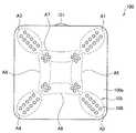
例えば、図8に示すように、略四角形のホバリングカメラ100の機体平面100aに対して、その中心部と、四隅、各辺の中央部分に光源106を配置して、照明装置105を構成してもよい。さらに、ホバリングカメラの機体側面100bにも光源106を配置してもよい。なお、光源106は、ホバリングカメラ100の機体表面のいずれの位置にも設置可能であり、機体平面100a、機体側面100b以外にも、機体底面に設けてもよい。また、光源106は、図8に示すように、撮影対象と対向する面に、2次元配列状に設けられてもよい。 For example, as shown in FIG. 8, a
このとき、光源106の設置位置に応じて光源106の出射方向を適宜設定することで、撮影範囲Sにおける照度分布を略均一とすることができる。例えば、図8に示すように、機体平面100aに配置された光源106のうち、中心部に設けられた光源106の光の出射方向は機体平面100aに対して略垂直にする。一方、機体平面100aの周囲に設けられた光源106については、光の出射方向を機体平面100aに対して垂直となる方向から機体の外部に向けて傾斜させるようにしてもよい。 At this time, the illuminance distribution in the photographing range S can be made substantially uniform by appropriately setting the emission direction of the
また、照明装置105の他の構成例として、例えば図9に示すように、略四角形のホバリングカメラ100の機体平面100aに対して対角線上に光源106を配置して、照明装置105を構成してもよい。この場合にも、図8の照明装置105と同様、撮影範囲Sにおける照度分布が略均一となるように、各光源106の指向性を適宜変更してもよい。 Further, as another configuration example of the
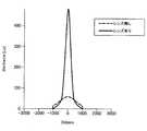
ここで、照明装置105の撮影範囲Sにおける照度分布を略均一にする方法としては、光源106の光の出射方向を調整する以外に、例えば光源106の指向性を調整する光学部材であるレンズ(図示せず。)を光源106に設けてもよい。例えば、図10に、指向角を小さくし、照度を大きくすることの可能なレンズについて、当該レンズを光源106の光の出射方向に設けた場合とレンズを設けない光源106の場合とでの指向性および照度の違いの一例を示す。図10に示すように、レンズなしの光源106では、指向性はあるものの照度に高いピークはなかったが、当該レンズを用いた光源106では、照度に著しいピークが現れるようになり、ある特定の部分に対して強い光を照射することが可能となる。 Here, as a method of making the illuminance distribution in the photographing range S of the
このようなレンズを用いて光源106の指向性を変化させ、照射される光の照度を高めることで、撮影範囲Sにおける照度分布を略均一にすることができる。特に、後述にするように、本実施形態に係るホバリングカメラ100では、機体の傾きに応じて照明装置105の光量を調整し、撮影範囲Sにおける照度分布を略均一にする。 By changing the directivity of the
具体的には、ホバリングカメラ100の照明装置105を構成する光源106の少なくとも一部に、指向性を変化させ、照射される光の照度を高めるレンズを設けることで、より精度よく撮影範囲Sにおける照度分布を略均一にすることができる。例えば、図9に示した照明装置105の例では、機体平面100aの対角線上に配置された光源106のうち、四隅に近い領域A1〜A4に配置された光源106について、指向性を変化させ、照射される光の照度を高めるレンズを設けてもよい。また、中心部近くの領域A5〜A8に配置された光源106については、レンズを設けないようにしてもよい。 Specifically, at least a part of the
なお、図8および図9に示した照明装置105では、ホバリングカメラ100の機体を簡略化して略四角体で表現したが、実際のホバリングカメラ100は、機体表面が曲面とされてもよい。この場合、照明装置105を構成する各光源106の光の出射方向は、機体の表面形状に応じて適宜設定してもよい。また、上記例で示した、光源106の指向性を変化させるレンズは、一例であって、使用するレンズの特性(レンズにより調整される指向角やピーク照度等)は上記例に限定されない。また、複数の特性を有するレンズを使用して、複数の異なる指向性の光源106を構成し、これらを組み合わせて撮影範囲Sにおける照度分布を略均一にするようにしてもよい。 In the
(3)機体の傾きに応じた照明装置の光量制御
本実施形態に係るホバリングカメラ100は、制御部110により、機体の傾きに応じて照明装置105の光量を調光する。上述のように、本実施形態に係る照明装置105は、撮影範囲Sにおける照度分布が略均一となるように設計されているが、このような照明装置105であっても風等に対抗して機体が傾いた状態になると、撮影位置での撮影範囲Sの目標照度分布が実現できなくなる。例えば、撮影時、ホバリングカメラ100の機体平面100aは撮影面に対して設定距離dを保持した状態で略平行となるように姿勢制御がなされるが、例えば風等の影響によりホバリングカメラ100が傾くことがある。そうすると、撮影面に対してホバリングカメラ100の機体平面100aが傾き、機体平面100aの外周部に設けられた光源106については、光源106から撮影面までの距離が設定距離dよりも大きくなることがある。(3) Light amount control of illumination device according to inclination of body The hovering
そこで、制御部110は、機体に搭載したセンサ部130により検知されたホバリングカメラ100の機体の傾きに応じて、照明装置105の光量を制御し、撮影位置での撮影範囲Sの照度分布が略均一となるようにする。照明装置105は機体に固定させたままでよく、撮像装置101の傾きのみ調整すればよいので、ホバリングカメラ100の可動部分の駆動機構を簡略化することができ、結果として、ホバリングカメラ100を軽量化することが可能となる。 Therefore, the
図11および図12に基づき、照明装置105の光量制御についてより詳細に説明する。以下では、水平な基準面に対して機体が傾いている場合のホバリングカメラ100の機体の傾きに応じた光量制御と、撮影対象に対するホバリングカメラ100の機体の傾きに応じた光量制御とについて説明する。なお、図11においては、ホバリングカメラ100の撮像装置101および照明装置105を模式的に示している。図11では、撮像装置101による撮像方向を分かりやすくするために照明装置105の発光面105a上に撮像装置101を記載しているが、撮像装置101の設置位置は、この位置に限定されず、例えば図2のようにホバリングカメラ100の一側面でもよい。 The light amount control of the
まず、水平な基準面に対して機体が傾いている場合のホバリングカメラ100の機体の傾きに応じた光量制御について説明する。例えば、図1に示すような、橋梁1の橋桁3の裏面部が水平面と略平行であるとき、この裏面部に対してホバリングカメラ100の機体が傾いている場合に実行される制御である。 First, the light amount control of the hovering
まず、制御部110は、センサ部130により取得された情報に基づき、ホバリングカメラ100の機体の傾きを取得する。このとき、制御部110は、センサ部130からの情報として、ホバリングカメラ100に複数箇所に設けられたレーザーレンジファインダのセンシング情報を用いて、ホバリングカメラ100が撮影対象の撮影面に対して傾いているか否かを判定する。ホバリングカメラ100が撮影対象の撮影面に対して傾いているか否かは、例えば、ホバリングカメラ100の同一平面に設けられた複数のレーザ―レンジファインダにより測定された距離のうち少なくとも1つが異なる値であるかによって判定してもよい。 First, the
各レーザ―レンジファインダにより測定された距離が略同一であるとき(例えば、各距離の差分が所定の範囲内にあるとき)には、撮影範囲Sにおける照度分布が略均一になると判定し、制御部110は照明装置105の光量制御を行わないことを決定する。一方、各レーザ―レンジファインダにより測定された距離のうち少なくとも1つが異なる値である場合、制御部110は、ホバリングカメラ100が撮影対象の撮影面に対して傾いていると判定する。そして、制御部110は、本例では撮影対象の撮影面が水平面と略平行であることから、水平面Pを基準として、水平面Pに対して発光面105aが傾いた角度θを取得する。角度θは、センサ部130からの情報として、例えば加速度センサの加速度の情報やジャイロセンサによる角速度の情報を用いて取得可能である。 When the distances measured by each laser-range finder are substantially the same (for example, when the difference between the distances is within a predetermined range), it is determined that the illuminance distribution in the photographing range S is substantially uniform, and control is performed. The
水平面Pに対して発光面105aが角度θ傾くと、水平面Pに略平行な撮影面Waにおける照明装置105から照射された光の照度分布に偏りが生じる。例えば、図11では、紙面右側(R)が撮影面Waから離隔する(すなわち、紙面左側(L)が撮影面Waに近づく)ように傾斜している。このとき、右側(R)に配置された光源106の光量と左側(L)に配置された光源の光量とが同一であったとすると、撮影面Waから離れている右側(R)の光源106の光は、左側(L)の光源からの光より撮影面Waに届きにくい。このため、撮影面Waにおける照度分布は、左側(L)に比べて右側(R)が暗くなり、撮影範囲Sの照度が略均一とならない。 When the
そこで、本実施形態では、水平面Pに対する発光面105aの傾斜角θに応じて、照明装置105を構成する光源106の光量を調整することで、撮影面Waにおける照度分布を略均一とする。例えば、水平面Pに対する発光面105aの傾斜角を20°としたときの、照明装置105の光源106の光の出力割合と、撮影面Waの撮影範囲Sの右上領域と左上領域とにおける照度の差分とを図12に示す。ここでは、撮影範囲Sを、図12上側に示すように、中心領域Cと、撮影範囲Sを左右上下に分割して形成された右上領域UR、左上領域UL、右下領域BR、左下領域BLとの5つの領域に分割した。 Therefore, in the present embodiment, the illuminance distribution on the photographing surface Wa is made substantially uniform by adjusting the amount of light of the
そして、右領域(右上領域UR、右下領域BR)に対向する光源106と、左領域(左上領域UL、左下領域BL)に対向する光源106とについて、光の出力割合を変化させ、そのときの右上領域URと左上領域ULとの照度差を測定した。なお、照明装置105を構成する各光源106の特性は同一であり、各光源106の光量の調整量は、光源106が出力可能な最大定格での光量を100%としたときの割合により表した。この結果を図12下側のグラフに示す。 Then, the light output ratio of the
図12下側に示すように、まず、右領域に対向する光源106と左領域に対向する光源106との光の出力割合をすべて50%とし、照明装置105を構成するすべての光源106を同一光量で発光させたとする。このとき、右上領域URと左上領域ULとの照度差は83[lux]であった。その後、右領域に対向する光源106の光の出力割合を徐々に大きくするとともに、左領域に対向する光源106の光の出力割合を徐々に小さくすると、図12下側に示すように、右上領域URと左上領域ULとの照度差は小さくなっていった。そして、右領域に対向する光源106の光の出力割合を約85%、左領域に対向する光源106の光の出力割合を約25%としたとき、撮影範囲Sにおける右上領域URと左上領域ULとの照度差が略ゼロとなることがわかる。
As shown in the lower part of FIG. 12, first, the light output ratios of the
このように、撮影範囲Sにおける各領域の照度差を略ゼロとなるように光源106の光量を調整すれば、撮影範囲Sの照度分布を略均一とすることができる。 As described above, by adjusting the light amount of the
ホバリングカメラ100は、水平面Pに対する発光面105aの傾斜角θ毎に、撮影範囲Sの各領域における照度差が所定値以下となる各光源106の出力値を、記憶部140に予め記憶している。設定する各光源106の出力値は、例えば実機による測定結果に基づき決定してもよく、シミュレーション結果に基づき決定してもよい。ホバリングカメラ100の制御部110は、センサ部130の測定結果より取得された機体の傾きに対応する照明装置105の設定値を記憶部140から取得し、照明制御部115にて、照明装置105の各光源106の出力(光量)を制御する。 The hovering
なお、照明制御部115は、照明装置105を構成する各光源106をそれぞれ制御してもよく、所定のまとまり毎に各光源106を制御してもよい。例えば、図9に示すような照明装置の場合、8つの領域A1〜A8毎に制御してもよい。 Note that the
一方、撮影対象に対するホバリングカメラ100の機体の傾きに応じて光量制御をしてもよい。例えば、橋梁の橋桁の裏面部等の撮影対象が水平面に対して傾斜しており、かつ、撮影対象に対してホバリングカメラ100の機体の傾きも傾斜している場合には、以下のように撮影対象に対するホバリングカメラ100の機体の傾きを算出し、照明装置105の光量制御を行ってもよい。 On the other hand, light amount control may be performed according to the inclination of the body of the hovering
この場合にも、制御部110は、センサ部130により取得された情報に基づき、ホバリングカメラ100の機体の傾きを取得する。ホバリングカメラ100の機体の傾きは、上述と同様、センサ部130からの情報として、ホバリングカメラ100に複数箇所に設けられたレーザーレンジファインダのセンシング情報を用いて取得してもよい。各レーザーレンジファインダにより測定された距離がすべて略同一ではないとき、撮影対象の撮影面に対してホバリングカメラ100の機体は傾斜していると判定される。
Also in this case, the
撮影対象の撮影面に対してホバリングカメラ100の機体は傾斜しているとき、制御部110は、撮影対象に対するホバリングカメラ100の機体の傾斜角を算出し、照明装置105の光量制御に利用する。撮影対象に対するホバリングカメラ100の機体の傾斜角は、例えば、水平面Pに対する撮影対象の撮影面の傾きが既知の場合には、水平面Pに対する撮影対象の撮影面の傾きと、ジャイロセンサを用いて取得された水平面Pに対する機体の傾きとから取得可能である。あるいは、複数のレーザーレンジファインダより測定された距離から幾何学的に撮影対象に対するホバリングカメラ100の機体の傾斜角を取得してもよい。 When the body of the hovering
制御部110は、撮影対象に対するホバリングカメラ100の機体の傾斜角を取得すると、機体の傾きに対応する照明装置105の設定値を記憶部140から取得し、照明制御部115にて、照明装置105の各光源106の出力(光量)を制御する。なお、記憶部140に記憶されている設定値は、上述のように水平面Pに対する機体の傾斜角θに基づいて光量制御を行う際に利用される情報と同一であってもよい。 When acquiring the inclination angle of the body of the hovering
[5.3.撮影時における撮像装置および照明装置の制御例]
以下、図13〜図15に基づいて、本実施形態に係るホバリングカメラ100による撮影時の、撮像装置101および照明装置105の一制御例について説明する。なお、図13は、本実施形態に係るホバリングカメラ100による撮影時の、撮像装置101および照明装置105の一制御例をフローチャートである。図14は、撮像装置101のシャッター制御の一例について説明するフローチャートである。図15は、飛行情報に基づく撮影作業時における、ホバリングカメラ100の速度および加速度の変化状況を示す概念図である。[5.3. Example of control of imaging device and lighting device at the time of shooting]
Hereinafter, one control example of the
飛行情報に基づく撮影作業を開始すると、ホバリングカメラ100は、まず、撮像装置101および照明装置105の設定情報である撮影パラメータを設定する(ステップS200)。撮影パラメータは、例えば撮像装置101のシャッタースピードや撮影ゲイン、照明装置105の設定照度等がある。撮影パラメータは、例えばホバリングカメラ100の記憶部140に予め設定されている。撮影パラメータ設定部111は、撮像画像に要求される画像品質を得るために必要な撮影パラメータを記憶部140から取得し、撮像装置101や照明装置105に対して設定するため、照明制御部115およびシャッター制御部117へ出力する。 When the photographing operation based on the flight information is started, the hovering
次いで、検出情報取得部113により、センサ部130や位置情報取得部132により取得された機体の位置情報や撮像時の機体情報を取得する(ステップS202)。例えば検出情報取得部113は、取得した各種情報を、照明制御部115およびシャッター制御部117へ出力する。これにより、照明制御部115およびシャッター制御部117は、ステップS200にて設定された撮影パラメータとなるよう、照明装置105や撮像装置101の制御を開始することが可能となる。 Next, the detection
ホバリングカメラ100は、撮影ポイントに到達するまでは、撮影ポイントまでの移動を行い続ける。ここで、ホバリングカメラ100が、撮影ポイントを含む所定の範囲である撮影エリアに進入すると、撮影ポイントが近付いたため、制御部110により撮影準備を開始する(ステップS204)。まず、照明制御部115により、照明装置105が点灯される(ステップS206)。照明装置105は撮影ポイントまでの移動中に点灯していてもよいが、撮影時に撮影範囲Sに対して照明を行ってもよい。撮影ポイントに近い撮影エリアに進入したときに、照明装置105を点灯すると照明装置105の点灯時間を短くすることができ、消費バッテリも抑制することができる。 The hovering
撮影エリアへの進入は、例えば、ホバリングカメラ100が撮影ポイントにて静止するために減速し始める時点で撮影エリアへ進入したと判定してもよい。あるいは、撮影ポイントから所定の距離内の領域を撮影エリアとして規定し、機体の位置情報からホバリングカメラ100が当該撮影エリア内にいることを特定したときに、撮影エリアにホバリングカメラ100が進入したと判定してもよい。
Theentry into the shooting area may be determined, for example, as havingentered the shooting area when the hovering
照明装置105が点灯されると、上述したように、機体情報から得られる機体の傾きに応じて、照明装置105の各光源106の調光が行われる。この調光は、撮影ポイントにおいて、設定パラメータにより設定された設定照度が確保され、かつ、撮影面の撮影範囲Sにおける照度分布が略均一となるように行われる。 When the
次いで、シャッター制御部117により、撮像装置101のシャッター制御が開始される(ステップS208)。シャッター制御部117は、ホバリングカメラ100が撮影ポイントに到達したとき、撮像装置101のシャッターを切り、撮影ポイントで画像を取得する。このとき、ホバリングカメラ100の姿勢が安定した状態であれば、撮影された画像にブレが生じにくく、より高精度な画像を取得できる。そこで、シャッター制御部117は、ホバリングカメラ100の姿勢が安定したか否かを判断するため、図14に示すように、ホバリングカメラ100の速度の絶対値が閾値速度vthより小さく、かつ、加速度の絶対値が閾値加速度athより小さくなったかを判定する(ステップS2081)。Next, shutter control of the
例えば、図15に示すように、ホバリングカメラ100が撮影エリアに進入し、線形的に速度が減少されると、ホバリングカメラ100の加速度は負の値の放物線を描くように変化する。一方、撮影ポイントでの撮影を終了し、次の撮影ポイントへ移動を開始するため、ホバリングカメラ100の速度が線形的に増加すると、加速度は正の値の放物線を描くように変化する。しかし、ホバリングカメラ100が移動しないときには、速度および加速度は略ゼロとなり、ホバリングカメラ100は静止状態に近い安定した状態となっている。このとき、ホバリングカメラ100の機体の振動は小さいので、撮像装置101は機体の振動の影響を大きく受けることなく撮影を行うことができる。閾値速度vthおよび閾値加速度athは、例えば、略ゼロに近い正の値に設定される。
For example, as shown in FIG. 15, when the hovering
そして、ホバリングカメラ100の速度の絶対値が閾値速度vthより小さく、かつ、加速度の絶対値が閾値加速度athより小さくなったとき、シャッター制御部117はシャッターを駆動させて撮影する(ステップS2083)。このとき、撮像装置101のシャッタースピードは、図13のステップS200にて設定された露光時間に基づき決定される。したがって、撮像装置101による撮影は機体の振動の影響を除去できるシャッタースピードで行われるため、ブレの少ない、高精度な画像を取得することができる。When the absolute value of the speed of the hovering
なお、図14に示したシャッター制御処理は、図13のステップS208〜S214の間に実行される処理である。 The shutter control process shown in FIG. 14 is a process executed between steps S208 to S214 in FIG.
図13の説明に戻り、ステップS208にてシャッター制御部117によるシャッター制御が開始され、ステップS214でシャッター制御が終了されるまでの間、照明制御部115は、ホバリングカメラ100の機体の傾きに応じて照明装置105の調光を行い続ける。なお、撮影の露光時間中は調光動作を中断し、光源状態を固定してもよい。そして、図14のステップS2083にてシャッターが作動し、撮影が完了すると(ステップS212)、シャッター制御部117によるシャッター制御が終了し(ステップS214)、照明制御部115により照明装置105が消灯される(ステップS216)。 Returning to the description of FIG. 13, until the shutter control by the
その後、制御部110は、飛行情報にて設定されたすべての撮影ポイントでの撮影がすべて完了したか否かを判定する(ステップS218)。ステップS218にて撮影が完了していない撮影ポイントがある場合には、ホバリングカメラ100は次の撮影ポイントへ移動し、(ステップS220)、ステップS202からの処理を繰り返し実行する。一方、ステップS218にてすべての撮影ポイントでの撮影が完了した場合には、ホバリングカメラ100はベースステーション600へ戻り、作業を終了する。 After that, the
以上、本実施形態に係るホバリングカメラ100による撮影時の、撮像装置101および照明装置105の一制御例について説明した。なお、上述の説明では、照明制御部115による照明装置105の調光と、シャッター制御部117によるシャッター制御との両方を実施する場合について説明したが、本開示はかかる例に限定されない。照明制御部115による照明装置105の調光と、シャッター制御部117によるシャッター制御とは、それぞれ独立して実行可能である。 In the above, one control example of the
[5.4.撮像装置のレンズ傾き制御]
本実施形態に係るホバリングカメラ100の制御部110は、図6に示したように、撮像装置101のレンズの傾きを制御する姿勢制御部119を備える。撮像装置101は、撮像装置101による撮影方向をチルト方向に変更可能なように、撮像装置101のレンズをチルト方向に回転させる第1の駆動部を備えている。これにより、機体の傾きによらず、同一位置を撮影し続けることができる。[5.4. Lens tilt control of imaging device]
The
また、本実施形態に係るホバリングカメラ100は、より高精度な画像を取得するため、さらに、ロール方向におけるレンズの傾きを調整する第2の駆動部を備えてもよい。これにより、例えば風等の外乱等によって100Hz以下の低周波数の振動が機体に発生した場合にも、姿勢制御部119により第2の駆動部を駆動してロール方向の傾きを調整することで、この振動が撮影に与える影響を除去できる。 In addition, the hovering
撮像装置101のレンズを駆動する第1の駆動部162および第2の駆動部164は、例えば図16および図17に示すように設けることができる。図16は、本実施形態に係るホバリングカメラ100の下フレーム部107の概略正面図である。図17は、撮像装置101のレンズを駆動する第1の駆動部162および第2の駆動部164を平面側から示す概略斜視図である。
The
図16に示すように、撮像装置101は、例えばホバリングカメラ100の下フレーム部107の正面(Y軸正方向)を向いて設けられる。撮像装置101のレンズは、図17に示すように、第1の駆動部162によりチルト方向に回転可能に設けられている。これにより、撮像装置101の撮影方向は、下方から正面、さらに上方を向くように設定することができる。また、本実施形態に係る撮像装置101のレンズは、図17に示すように、例えば撮像装置101の背面側(Y軸負方向側、ホバリングカメラ100の内部側)に設けられた第2の駆動部164によりロール方向に回転可能に設けられている。第2の駆動部164は、例えば撮像装置101が正面を向いた状態から±15°程度、レンズをロール方向に回転させることができる。 As shown in FIG. 16, the
このように、レンズに2軸のサーボ機構を設けることで、機体の傾きによらず同一位置を撮影できるだけでなく、低周波数の振動を除去することも可能となり、より高精度な画像を取得することが可能となる。 By providing a two-axis servo mechanism on the lens in this way, not only can the same position be photographed irrespective of the inclination of the body, but also low-frequency vibration can be removed, and a more accurate image can be obtained. It becomes possible.
<6.まとめ>
以上、本開示の一実施形態に係る点検システム10を構成するホバリングカメラ100の構成とそれによる点検作業、画像取得時の照明装置105および撮像装置101の制御について説明した。このようなホバリングカメラ100では、大型のジンバルや一眼レフ等を用いることなく、機体の姿勢や飛行体に搭載した撮像装置101や照明装置105の撮影条件を制御する。<6. Summary>
In the above, the configuration of the hovering
例えば、ホバリングカメラ100に照明装置105を備え、照明制御部115により機体の傾きをホバリングカメラ100内部のセンサ部130にて検知し、機体の傾きに応じて照明装置105の光量を調整する。これにより、撮影面での照度を一定値以上に略均一に保つことができ、撮像装置101のパラメータを変更せずに、一定の品質の画像を得ることが可能となる。 For example, the hovering
また、撮像装置101の撮影パラメータであるシャッタースピードを速くすることで、通常の手振れ補正では対応できない高周波数の振動の影響を除去する。これにより、ブレの少ない高精度の画像を取得することが可能となる。また、撮像装置101のレンズをチルト方向およびロール方向の2軸に回転駆動可能なサーボ機構を備えるようにして、撮影方向を一定に保つとともに、低周波数の振動の影響を除去することもできるようになる。 In addition, by increasing the shutter speed, which is a shooting parameter of the
以上、添付図面を参照しながら本開示の好適な実施形態について詳細に説明したが、本開示の技術的範囲はかかる例に限定されない。本開示の技術分野における通常の知識を有する者であれば、特許請求の範囲に記載された技術的思想の範疇内において、各種の変更例または修正例に想到し得ることは明らかであり、これらについても、当然に本開示の技術的範囲に属するものと了解される。 As described above, the preferred embodiments of the present disclosure have been described in detail with reference to the accompanying drawings, but the technical scope of the present disclosure is not limited to such examples. It is apparent that a person having ordinary knowledge in the technical field of the present disclosure can conceive various changes or modifications within the scope of the technical idea described in the claims. It is understood that also belongs to the technical scope of the present disclosure.
例えば、上記実施形態では、撮影面における撮影範囲Sの照度分布を略均一とするため、撮像装置101の傾きのみを調整し、照明装置105は光量を調整して撮影面に照射されたときの照度を略均一としたが、本技術はかかる例に限定されない。例えば、撮像装置101と照明装置105とを一体化し、これらの傾きを調整することで、撮影面における撮影範囲Sの照度分布を略均一とすることも可能である。この場合、撮像装置101と照明装置105とを一体として制御できるため、撮影に必要な撮影範囲Sの照度分布を容易に設定することができる。なお、撮像装置101と照明装置105とを一体化した場合には、ホバリングカメラ100における可動部分が大きくなるため、全体的に重量が大きくなることが考えられる。 For example, in the above embodiment, in order to make the illuminance distribution of the imaging range S on the imaging surface substantially uniform, only the inclination of the
また、本明細書に記載された効果は、あくまで説明的または例示的なものであって限定的ではない。つまり、本開示に係る技術は、上記の効果とともに、または上記の効果に代えて、本明細書の記載から当業者には明らかな他の効果を奏しうる。 Further, the effects described in this specification are merely illustrative or exemplary, and are not restrictive. That is, the technology according to the present disclosure can exhibit other effects that are obvious to those skilled in the art from the description in the present specification, in addition to or instead of the above effects.
なお、以下のような構成も本開示の技術的範囲に属する。
(1)
撮影対象を撮影する撮像装置と、撮影対象を照明する照明装置と、を備える飛行体デバイスの、機体の傾きに応じて、前記照明装置の光量を調節する照明制御部を備える、制御装置。
(2)
前記機体の傾きは、水平面に対する傾きである、前記(1)に記載の制御装置。
(3)
前記機体の傾きは、前記撮影対象に対する傾きである、前記(1)に記載の制御装置。
(4)
前記照明制御部は、前記撮影対象の撮影面における照度が略一定となるように前記照明装置の光量を調節する、前記(1)〜(3)のいずれか1項に記載の制御装置。
(5)
前記照明制御部は、前記飛行体デバイスから前記撮影対象を撮影する撮影ポイント付近の撮影エリアに進入したとき、前記照明装置を点灯させる、前記(1)〜(4)のいずれか1項に記載の制御装置。
(6)
前記撮像装置のシャッターを制御するシャッター制御部を備え、
前記シャッター制御部は、前記飛行体デバイスの移動速度が所定値以下、かつ、前記飛行体デバイスの移動加速度が所定値以下であるとき、前記シャッターを操作する、前記(1)〜(5)のいずれか1項に記載の制御装置。
(7)
撮影対象を撮影する撮像装置と、撮影対象を照明する照明装置と、を備える飛行体デバイスの、撮影対象に対する機体の傾きを取得すること、
前記機体の傾きに応じて、前記照明装置の光量を調節すること、
を含む、制御方法。
(8)
撮影対象を撮影する撮像装置と、
撮影対象を照明する照明装置と、
撮影対象に対する機体の傾きに応じて、前記照明装置の光量を調節する制御部と、
を備える、飛行体デバイス。
(9)
前記制御部は、前記撮影対象の撮影面における照度が略一定となるように前記照明装置の光量を調節する、前記(8)に記載の飛行体デバイス。
(10)
前記照明装置は、複数のLED光源を含む、前記(8)または(9)に記載の飛行体デバイス。
(11)
複数の光源は、前記飛行体デバイスを構成する1または複数の面であって、前記撮影対象に対向する面に対して2次元配列状に設置される、前記(10)に記載の飛行体デバイス。
(12)
前記複数の光源は複数の領域に設置され、
前記制御部は、前記機体の傾きに応じて、前記複数の領域毎に前記複数の光源の光量を制御する、前記(11)に記載の飛行体デバイス。
(13)
前記複数の光源はLED光源を含む、前記(11)または(12)に記載の飛行体デバイス。
(14)
前記LED光源のうち、少なくとも一部のLED光源には、指向性を変化させる光学部材が設けられる、前記(10)〜(13)のいずれか1項に記載の飛行体デバイス。
(15)
前記撮像装置を、チルト方向に回転駆動する第1の駆動部と、
前記撮像装置を、ロール方向に回転駆動する第2の駆動部と、
を備える、前記(8)〜(14)のいずれか1項に記載の飛行体デバイス。Note that the following configuration also belongs to the technical scope of the present disclosure.
(1)
A control device for a flying object device including an imaging device for photographing a photographing target and a lighting device for illuminating the photographing target, the lighting device including a lighting control unit that adjusts a light amount of the lighting device according to a tilt of an airframe.
(2)
The control device according to (1), wherein the inclination of the body is an inclination with respect to a horizontal plane.
(3)
The control device according to (1), wherein the inclination of the body is an inclination with respect to the imaging target.
(4)
The control device according to any one of (1) to (3), wherein the lighting control unit adjusts a light amount of the lighting device so that illuminance on a shooting surface of the shooting target is substantially constant.
(5)
The lighting control unit according to any one of (1) to (4), wherein the lighting control unit turns on the lighting device when the lighting device enters a shooting area near a shooting point for shooting the shooting target from the flying object device. Control device.
(6)
A shutter control unit that controls a shutter of the imaging device,
The shutter control unit operates the shutter when the moving speed of the flying device is equal to or less than a predetermined value and the moving acceleration of the flying device is equal to or less than a predetermined value. The control device according to claim 1.
(7)
An imaging device that shoots a shooting target, and an illuminating device that illuminates the shooting target, of a flying device including:
Adjusting the light amount of the lighting device according to the inclination of the aircraft,
And a control method.
(8)
An imaging device for photographing a photographing target,
A lighting device for illuminating the object to be photographed;
A control unit that adjusts a light amount of the illumination device according to an inclination of the body with respect to a shooting target,
A flying object device comprising:
(9)
The flying object device according to (8), wherein the control unit adjusts the light amount of the illumination device so that the illuminance on the imaging surface of the imaging target is substantially constant.
(10)
The flying device according to (8) or (9), wherein the lighting device includes a plurality of LED light sources.
(11)
The flying device according to (10), wherein the plurality of light sources are one or more surfaces configuring the flying device, and are arranged in a two-dimensional array with respect to a surface facing the imaging target. .
(12)
The plurality of light sources are installed in a plurality of areas,
The flying object device according to (11), wherein the control unit controls light amounts of the plurality of light sources for each of the plurality of regions according to an inclination of the airframe.
(13)
The aircraft device according to (11) or (12), wherein the plurality of light sources include an LED light source.
(14)
The flying object device according to any one of (10) to (13), wherein at least some of the LED light sources are provided with an optical member that changes directivity.
(15)
A first driving unit that rotationally drives the imaging device in a tilt direction;
A second driving unit that rotationally drives the imaging device in a roll direction;
The flying object device according to any one of (8) to (14), further comprising:
10 点検システム
100 ホバリングカメラ
101 撮像装置
104a〜104d ロータ
105 照明装置
108a〜108d モータ
110 制御部
111 撮影パラメータ設定部
113 検出情報取得部
115 照明制御部
117 シャッター制御部
119 姿勢制御部
120 通信部
130 センサ部
132 位置情報取得部
140 記憶部
150 バッテリ
200 制御端末
300 情報処理装置
400 無線中継ノード
500 位置推定ノード
600 ベースステーション
700 充電ステーション
Claims (13)
Translated fromJapanese前記シャッター制御部は、前記飛行体デバイスの移動速度が所定値以下、かつ、前記飛行体デバイスの移動加速度が所定値以下であるとき、前記シャッターを操作する、請求項1〜4のいずれか1項に記載の制御装置。A shutter control unit that controls a shutter of the imaging device,
The shutter control unit is below a predetermined value the movement speed of the aircraft device, and, when the moving acceleration of the flying body device is less than a predetermined value, manipulating the shutter, claim1-4 1 The control device according to Item.
前記機体の傾きに応じて、前記撮影対象の撮影面における照度が所定の照度となるように前記照明装置の光量を調節すること、
を含む、制御方法。An imaging device that shoots a shooting target, and an illuminating device that illuminates the shooting target, of an aircraft device including: acquiring the inclination of the body with respect to the shooting target,
Adjusting the light amount of the lighting deviceso that the illuminance on the imaging surface of the imaging target becomes a predetermined illuminance according to the inclination of the body,
And a control method.
撮影対象を照明する照明装置と、
撮影対象に対する機体の傾きに応じて、前記撮影対象の撮影面における照度が所定の照度となるように前記照明装置の光量を調節する制御部と、
を備える、飛行体デバイス。An imaging device for photographing a photographing target,
A lighting device for illuminating the object to be photographed;
A control unit that adjusts a light amount of the illumination deviceso that an illuminance on an imaging surface of the imaging target is a predetermined illuminance according to an inclination of the body with respect to theimaging target ;
A flying object device comprising:
前記制御部は、前記機体の傾きに応じて、前記複数の領域毎に前記複数の光源の光量を制御する、請求項9に記載の飛行体デバイス。The plurality of light sources are installed in a plurality of areas,
The flying object device according to claim9 , wherein the control unit controls light amounts of the plurality of light sources for each of the plurality of regions according to an inclination of the airframe.
前記撮像装置を、ロール方向に回転駆動する第2の駆動部と、
を備える、請求項7〜12のいずれか1項に記載の飛行体デバイス。A first driving unit that rotationally drives the imaging device in a tilt direction;
A second driving unit that rotationally drives the imaging device in a roll direction;
The vehicle according to any one of claims7 to12 , comprising:
Priority Applications (1)
| Application Number | Priority Date | Filing Date | Title |
|---|---|---|---|
| JP2020018566AJP6930616B2 (en) | 2014-10-17 | 2020-02-06 | Controls, control methods and aircraft devices |
Applications Claiming Priority (3)
| Application Number | Priority Date | Filing Date | Title |
|---|---|---|---|
| JP2014212657 | 2014-10-17 | ||
| JP2014212657 | 2014-10-17 | ||
| PCT/JP2015/073674WO2016059877A1 (en) | 2014-10-17 | 2015-08-24 | Controller, control method, and flight vehicle device |
Related Child Applications (1)
| Application Number | Title | Priority Date | Filing Date |
|---|---|---|---|
| JP2020018566ADivisionJP6930616B2 (en) | 2014-10-17 | 2020-02-06 | Controls, control methods and aircraft devices |
Publications (2)
| Publication Number | Publication Date |
|---|---|
| JPWO2016059877A1 JPWO2016059877A1 (en) | 2017-07-27 |
| JP6658532B2true JP6658532B2 (en) | 2020-03-04 |
Family
ID=55746425
Family Applications (5)
| Application Number | Title | Priority Date | Filing Date |
|---|---|---|---|
| JP2016554003AActiveJP6658532B2 (en) | 2014-10-17 | 2015-08-24 | Control device, control method, and flying object device |
| JP2020018566AActiveJP6930616B2 (en) | 2014-10-17 | 2020-02-06 | Controls, control methods and aircraft devices |
| JP2021130748AActiveJP7226487B2 (en) | 2014-10-17 | 2021-08-10 | Control device and control method |
| JP2023015473APendingJP2023052898A (en) | 2014-10-17 | 2023-02-03 | Control device and control method |
| JP2025060539APendingJP2025096325A (en) | 2014-10-17 | 2025-04-01 | Control device and control method |
Family Applications After (4)
| Application Number | Title | Priority Date | Filing Date |
|---|---|---|---|
| JP2020018566AActiveJP6930616B2 (en) | 2014-10-17 | 2020-02-06 | Controls, control methods and aircraft devices |
| JP2021130748AActiveJP7226487B2 (en) | 2014-10-17 | 2021-08-10 | Control device and control method |
| JP2023015473APendingJP2023052898A (en) | 2014-10-17 | 2023-02-03 | Control device and control method |
| JP2025060539APendingJP2025096325A (en) | 2014-10-17 | 2025-04-01 | Control device and control method |
Country Status (6)
| Country | Link |
|---|---|
| US (4) | US10011371B2 (en) |
| EP (2) | EP3193496B1 (en) |
| JP (5) | JP6658532B2 (en) |
| CN (2) | CN106797438B (en) |
| CA (1) | CA2960749A1 (en) |
| WO (1) | WO2016059877A1 (en) |
Families Citing this family (24)
| Publication number | Priority date | Publication date | Assignee | Title |
|---|---|---|---|---|
| JP6658532B2 (en) | 2014-10-17 | 2020-03-04 | ソニー株式会社 | Control device, control method, and flying object device |
| EP3309581A1 (en)* | 2016-10-12 | 2018-04-18 | STMicroelectronics (Research & Development) Limited | Apparatus for controlling driver current for illumination source |
| WO2018098607A1 (en)* | 2016-11-29 | 2018-06-07 | SZ DJI Technology Co., Ltd. | Method and system of adjusting image focus |
| WO2018150369A1 (en)* | 2017-02-17 | 2018-08-23 | Verity Studios Ag | Methods of taking a measurement |
| JP6579523B2 (en)* | 2017-05-02 | 2019-09-25 | 株式会社プロドローン | Flight function addition device and rotor unit |
| CN107607543A (en)* | 2017-09-08 | 2018-01-19 | 上海振华重工(集团)股份有限公司 | The inspection device and method for inspecting of harbour machinery |
| JP2019083488A (en)* | 2017-10-31 | 2019-05-30 | キヤノン株式会社 | Imaging device, support device, method of controlling them, and program |
| CN108600581A (en)* | 2017-12-27 | 2018-09-28 | 北京臻迪科技股份有限公司 | Unmanned vehicle |
| EP3770070B1 (en)* | 2018-03-19 | 2023-07-19 | Honda Motor Co., Ltd. | Aerial vehicle and control method for aerial vehicle |
| JP2020005146A (en)* | 2018-06-28 | 2020-01-09 | 株式会社リコー | Output control device, display terminal, information processing apparatus, movable body, remote control system, output control method, program, and photographing control device |
| CN110720210B (en) | 2018-07-11 | 2021-06-15 | 深圳市大疆创新科技有限公司 | Lighting equipment control method, equipment, aircraft and system |
| JP6878375B2 (en)* | 2018-09-28 | 2021-05-26 | エスゼット ディージェイアイ テクノロジー カンパニー リミテッドSz Dji Technology Co.,Ltd | Information processing equipment, flight control instruction method, program, and recording medium |
| CN109625254A (en)* | 2018-12-28 | 2019-04-16 | 浙江星米体育有限公司 | Sports class unmanned plane |
| CN109885098B (en)* | 2019-04-11 | 2022-02-11 | 株洲时代电子技术有限公司 | Method for planning inspection route of bridge side fence |
| CN111345031B (en)* | 2019-04-25 | 2021-10-15 | 深圳市大疆创新科技有限公司 | UAV and its shooting control method |
| CN113727938A (en)* | 2019-04-26 | 2021-11-30 | 住友重机械建机起重机株式会社 | Crane maintenance system and crane |
| WO2020262105A1 (en)* | 2019-06-27 | 2020-12-30 | 株式会社Nttドコモ | Information processing device |
| EP3766787B1 (en)* | 2019-07-14 | 2023-01-04 | Goodrich Lighting Systems GmbH | Method of indicating a flight direction of an aerial vehicle, flight direction indication system for an aerial vehicle, and aerial vehicle |
| JP7321050B2 (en)* | 2019-10-15 | 2023-08-04 | 水ing株式会社 | System for inspecting water supply facilities |
| CN115917352A (en)* | 2020-06-25 | 2023-04-04 | 索尼集团公司 | Device and method for avoiding collisions |
| JP7474976B2 (en)* | 2020-08-06 | 2024-04-26 | 日本電信電話株式会社 | Unmanned aerial vehicle and lighting control method |
| CN112357110B (en)* | 2020-09-22 | 2022-04-08 | 成都飞机工业(集团)有限责任公司 | Aircraft taxiing lamp installation angle calibration system and method based on laser positioning principle |
| WO2022082439A1 (en)* | 2020-10-20 | 2022-04-28 | 深圳市大疆创新科技有限公司 | Method and apparatus for time-lapse photographing of track, and gimbal camera, unmanned aerial vehicle, and handheld gimbal |
| CN116723382B (en)* | 2022-02-28 | 2024-05-03 | 荣耀终端有限公司 | Shooting method and related equipment |
Family Cites Families (69)
| Publication number | Priority date | Publication date | Assignee | Title |
|---|---|---|---|---|
| GB253067A (en)* | 1925-06-03 | 1926-06-17 | Albino Baudino | Improvements in and connected with polishing discs |
| JPH0693881B2 (en) | 1988-11-13 | 1994-11-24 | 伸子 滝本 | Perimeter |
| JPH02131741U (en)* | 1989-04-03 | 1990-11-01 | ||
| US6006158A (en)* | 1993-09-07 | 1999-12-21 | H. R. Pilley | Airport guidance and safety system incorporating lighting control using GNSS compatible methods |
| JPH05107622A (en)* | 1991-02-20 | 1993-04-30 | Asahi Optical Co Ltd | Blurred photograph preventing camera |
| US20020036617A1 (en)* | 1998-08-21 | 2002-03-28 | Timothy R. Pryor | Novel man machine interfaces and applications |
| JP4239128B2 (en)* | 2000-03-13 | 2009-03-18 | 富士フイルム株式会社 | Camera system |
| US9607301B2 (en)* | 2000-04-27 | 2017-03-28 | Merck Patent Gmbh | Photovoltaic sensor facilities in a home environment |
| US7688306B2 (en)* | 2000-10-02 | 2010-03-30 | Apple Inc. | Methods and apparatuses for operating a portable device based on an accelerometer |
| US6711280B2 (en)* | 2001-05-25 | 2004-03-23 | Oscar M. Stafsudd | Method and apparatus for intelligent ranging via image subtraction |
| JP2003110981A (en)* | 2001-09-28 | 2003-04-11 | Hiroboo Kk | Aerial video image processing system and wireless small- sized unmanned flying body |
| AU2002334708A1 (en)* | 2001-10-01 | 2003-04-14 | Kline And Walker, Llc | Pfn/trac system faa upgrades for accountable remote and robotics control |
| KR20030068871A (en)* | 2002-02-18 | 2003-08-25 | 서원무인기술(주) | Reconnoitering System using a Remotely Piloted Vehicle |
| JP2004053293A (en) | 2002-07-17 | 2004-02-19 | Mitsubishi Heavy Ind Ltd | Surface inspecting apparatus |
| JP4284949B2 (en) | 2002-09-05 | 2009-06-24 | ソニー株式会社 | Moving shooting system, moving shooting method, and shooting apparatus |
| FR2860623B1 (en)* | 2003-10-06 | 2005-12-30 | Mbda France | METHOD FOR TAKING PICTURES ON BOARD OF A ROTATING FLYING BODY AND SYSTEM IMPLEMENTING SAID METHOD |
| CN100370301C (en)* | 2003-12-05 | 2008-02-20 | 鸿富锦精密工业(深圳)有限公司 | Digital camera lens mould set regulating method |
| JP2005269413A (en) | 2004-03-19 | 2005-09-29 | Chugoku Electric Power Co Inc:The | Aerial photography system using unmanned air vehicle |
| JP2006027448A (en)* | 2004-07-16 | 2006-02-02 | Chugoku Electric Power Co Inc:The | Aerial imaging method and apparatus using unmanned air vehicle |
| JP2006162717A (en)* | 2004-12-03 | 2006-06-22 | Konica Minolta Photo Imaging Inc | Camera equipped with illuminator |
| US7750802B1 (en)* | 2005-02-11 | 2010-07-06 | Parish Warren G | Illumination and detection architecture |
| JP4740675B2 (en)* | 2005-07-25 | 2011-08-03 | イーストマン コダック カンパニー | Imaging device |
| JP2007212952A (en)* | 2006-02-13 | 2007-08-23 | Canon Inc | Strobe device of imaging device |
| US20150054639A1 (en)* | 2006-08-11 | 2015-02-26 | Michael Rosen | Method and apparatus for detecting mobile phone usage |
| US20090003822A1 (en)* | 2007-06-27 | 2009-01-01 | Frank Tyner | Hand-held photographic support system |
| JP2010006089A (en) | 2008-06-24 | 2010-01-14 | Kitakyushu Foundation For The Advancement Of Industry Science & Technology | Aerial photographing device of disaster-stricken, damaged and deteriorated state of facility such as for lifeline |
| JP5520457B2 (en)* | 2008-07-11 | 2014-06-11 | 任天堂株式会社 | GAME DEVICE AND GAME PROGRAM |
| JP5005731B2 (en)* | 2009-05-25 | 2012-08-22 | パナソニック株式会社 | Camera apparatus and exposure control method |
| US9128281B2 (en)* | 2010-09-14 | 2015-09-08 | Microsoft Technology Licensing, Llc | Eyepiece with uniformly illuminated reflective display |
| WO2011149558A2 (en)* | 2010-05-28 | 2011-12-01 | Abelow Daniel H | Reality alternate |
| CN101914893B (en)* | 2010-07-09 | 2011-07-27 | 重庆交通大学 | Bridge detection robot based on four-axle aircraft |
| JP5635333B2 (en)* | 2010-08-20 | 2014-12-03 | 公益財団法人鉄道総合技術研究所 | Radio control aircraft for reflective target formation |
| FR2964573B1 (en)* | 2010-09-15 | 2012-09-28 | Parrot | METHOD FOR CONTROLLING A MULTI-ROTOR ROTOR SAILING DRONE |
| DE102011010334B4 (en)* | 2011-02-04 | 2014-08-28 | Eads Deutschland Gmbh | Camera system and method for observing objects at a great distance, in particular for monitoring target objects at night, mist, dust or rain |
| FR2972364B1 (en)* | 2011-03-08 | 2014-06-06 | Parrot | METHOD FOR CONTROLLING FOLLOWING A CURVED TURNING OF A MULTI - ROTOR ROTOR SAILING DRONE. |
| IL217361A0 (en)* | 2012-01-04 | 2012-03-29 | Rafael Advanced Defense Sys | Device & method providing combined video camera and range finder functionality |
| IL217501A (en)* | 2012-01-12 | 2017-09-28 | Israel Aerospace Ind Ltd | System and method for maneuvering of an air vehicle |
| DE102012002067A1 (en)* | 2012-02-03 | 2013-08-08 | Eads Deutschland Gmbh | Air-to-ground monitoring and / or control system and method for airborne inspection and / or control of offshore or offshore objects |
| US20130233964A1 (en) | 2012-03-07 | 2013-09-12 | Aurora Flight Sciences Corporation | Tethered aerial system for data gathering |
| FR2988868B1 (en)* | 2012-03-30 | 2015-04-24 | Parrot | METHOD FOR CONTROLLING A MULTI-ROTOR ROTOR SAILING DRONE WITH ESTIMATION AND SIDE WIND COMPENSATION |
| US9609284B2 (en)* | 2012-05-22 | 2017-03-28 | Otoy, Inc. | Portable mobile light stage |
| US20140008496A1 (en)* | 2012-07-05 | 2014-01-09 | Zhou Ye | Using handheld device to control flying object |
| US20140018979A1 (en)* | 2012-07-13 | 2014-01-16 | Honeywell International Inc. | Autonomous airspace flight planning and virtual airspace containment system |
| JP6122591B2 (en)* | 2012-08-24 | 2017-04-26 | 株式会社トプコン | Photogrammetry camera and aerial photography equipment |
| EP2703836B1 (en)* | 2012-08-30 | 2015-06-24 | Softkinetic Sensors N.V. | TOF illuminating system and TOF camera and method for operating, with control means for driving electronic devices located in the scene |
| US10073336B2 (en)* | 2012-09-11 | 2018-09-11 | Barco N.V. | Projection system with safety detection |
| IL222053A (en)* | 2012-09-23 | 2016-11-30 | Israel Aerospace Ind Ltd | System, method and computer program product for maneuvering an air vehicle |
| JP6055274B2 (en)* | 2012-10-31 | 2016-12-27 | 株式会社トプコン | Aerial photograph measuring method and aerial photograph measuring system |
| JP2014113864A (en)* | 2012-12-07 | 2014-06-26 | Hitachi Solutions Ltd | Spray support device |
| CN103921933A (en)* | 2013-01-10 | 2014-07-16 | 深圳市大疆创新科技有限公司 | Deformation structure of air vehicle and micro air vehicle |
| WO2014161428A1 (en) | 2013-03-31 | 2014-10-09 | Sz Dji Technology, Co., Ltd. | Payload mounting platform |
| JP6429368B2 (en)* | 2013-08-02 | 2018-11-28 | 本田技研工業株式会社 | Inter-vehicle communication system and method |
| JP6187244B2 (en)* | 2013-12-25 | 2017-08-30 | ソニー株式会社 | Control apparatus, control method, and exposure control system |
| EP3099570B1 (en)* | 2014-01-31 | 2017-11-22 | Flir Systems, Inc. | Hydraulic slip compensation systems and methods |
| CN106489266B (en)* | 2014-04-14 | 2019-10-11 | 瓦斯菲·阿希达法特 | Announcer unmanned aerial vehicle |
| FR3020169A1 (en)* | 2014-04-16 | 2015-10-23 | Parrot | ROTATING WING DRONE WITH VIDEO CAMERA DELIVERING STABILIZED IMAGE SEQUENCES |
| GB2525900A (en)* | 2014-05-07 | 2015-11-11 | Imp Innovations Ltd | Method of using a device capable of controlled flight |
| ES2708579T3 (en)* | 2014-05-30 | 2019-04-10 | Sz Dji Technology Co Ltd | Methods of attitude control of aircraft |
| US9817396B1 (en)* | 2014-06-09 | 2017-11-14 | X Development Llc | Supervisory control of an unmanned aerial vehicle |
| US20160154170A1 (en)* | 2014-06-12 | 2016-06-02 | Nthdegree Technologies Worldwide Inc. | Ultra-thin display using thin flexible led light sheet |
| US9678506B2 (en)* | 2014-06-19 | 2017-06-13 | Skydio, Inc. | Magic wand interface and other user interaction paradigms for a flying digital assistant |
| WO2015200209A1 (en)* | 2014-06-23 | 2015-12-30 | Nixie Labs, Inc. | Wearable unmanned aerial vehicles, launch- controlled unmanned aerial vehicles, and associated systems and methods |
| WO2016015943A1 (en)* | 2014-08-01 | 2016-02-04 | Koninklijke Philips N.V. | System, device for creating an aerial image |
| US9746984B2 (en)* | 2014-08-19 | 2017-08-29 | Sony Interactive Entertainment Inc. | Systems and methods for providing feedback to a user while interacting with content |
| FR3025114A1 (en)* | 2014-08-26 | 2016-03-04 | Parrot | DYNAMIC START CONTROL METHOD LAUNCHING ROTARY SAIL DRONE |
| FR3027143B1 (en)* | 2014-10-10 | 2016-11-11 | Parrot | MOBILE APPARATUS, IN PARTICULAR ROTATING SAIL DRONE, PROVIDED WITH A VIDEO CAMERA DELIVERING IMAGE SEQUENCES DYNAMICALLY CORRECTED BY THE "WOBBLE" EFFECT |
| JP6658532B2 (en) | 2014-10-17 | 2020-03-04 | ソニー株式会社 | Control device, control method, and flying object device |
| EP3298458B1 (en)* | 2015-05-27 | 2019-12-18 | GoPro, Inc. | Camera system using stabilizing gimbal |
| FR3041136A1 (en)* | 2015-09-14 | 2017-03-17 | Parrot | METHOD FOR DETERMINING EXHIBITION DURATION OF AN ONBOARD CAMERA ON A DRONE, AND ASSOCIATED DRONE |
- 2015
- 2015-08-24JPJP2016554003Apatent/JP6658532B2/enactiveActive
- 2015-08-24CNCN201580054838.1Apatent/CN106797438B/enactiveActive
- 2015-08-24CNCN202010068084.8Apatent/CN111246060B/enactiveActive
- 2015-08-24USUS15/510,407patent/US10011371B2/enactiveActive
- 2015-08-24EPEP15851321.8Apatent/EP3193496B1/enactiveActive
- 2015-08-24WOPCT/JP2015/073674patent/WO2016059877A1/enactiveApplication Filing
- 2015-08-24EPEP20156076.0Apatent/EP3674214A1/ennot_activeWithdrawn
- 2015-08-24CACA2960749Apatent/CA2960749A1/ennot_activeAbandoned
- 2018
- 2018-05-30USUS15/993,052patent/US11530050B2/enactiveActive
- 2020
- 2020-02-06JPJP2020018566Apatent/JP6930616B2/enactiveActive
- 2021
- 2021-08-10JPJP2021130748Apatent/JP7226487B2/enactiveActive
- 2022
- 2022-11-15USUS17/986,928patent/US11884418B2/enactiveActive
- 2023
- 2023-02-03JPJP2023015473Apatent/JP2023052898A/enactivePending
- 2023-12-06USUS18/530,575patent/US20240109670A1/enactivePending
- 2025
- 2025-04-01JPJP2025060539Apatent/JP2025096325A/enactivePending
Also Published As
| Publication number | Publication date |
|---|---|
| JP2023052898A (en) | 2023-04-12 |
| US11530050B2 (en) | 2022-12-20 |
| CA2960749A1 (en) | 2016-04-21 |
| JP2021184634A (en) | 2021-12-02 |
| US20230070563A1 (en) | 2023-03-09 |
| JPWO2016059877A1 (en) | 2017-07-27 |
| EP3674214A1 (en) | 2020-07-01 |
| EP3193496A1 (en) | 2017-07-19 |
| CN106797438B (en) | 2020-03-06 |
| JP7226487B2 (en) | 2023-02-21 |
| WO2016059877A1 (en) | 2016-04-21 |
| US11884418B2 (en) | 2024-01-30 |
| US20240109670A1 (en) | 2024-04-04 |
| US20180273201A1 (en) | 2018-09-27 |
| JP2020080553A (en) | 2020-05-28 |
| EP3193496A4 (en) | 2018-04-11 |
| JP2025096325A (en) | 2025-06-26 |
| EP3193496B1 (en) | 2020-03-25 |
| CN111246060B (en) | 2022-01-18 |
| US10011371B2 (en) | 2018-07-03 |
| JP6930616B2 (en) | 2021-09-01 |
| CN111246060A (en) | 2020-06-05 |
| CN106797438A (en) | 2017-05-31 |
| US20170283088A1 (en) | 2017-10-05 |
Similar Documents
| Publication | Publication Date | Title |
|---|---|---|
| JP7226487B2 (en) | Control device and control method | |
| JP7605352B2 (en) | Information processing method, information processing device, and computer program | |
| JP7452743B2 (en) | Flight information control method, control device and computer program |
Legal Events
| Date | Code | Title | Description |
|---|---|---|---|
| A521 | Request for written amendment filed | Free format text:JAPANESE INTERMEDIATE CODE: A523 Effective date:20180809 | |
| A621 | Written request for application examination | Free format text:JAPANESE INTERMEDIATE CODE: A621 Effective date:20180809 | |
| RD04 | Notification of resignation of power of attorney | Free format text:JAPANESE INTERMEDIATE CODE: A7424 Effective date:20190208 | |
| RD03 | Notification of appointment of power of attorney | Free format text:JAPANESE INTERMEDIATE CODE: A7423 Effective date:20190214 | |
| RD04 | Notification of resignation of power of attorney | Free format text:JAPANESE INTERMEDIATE CODE: A7424 Effective date:20190222 | |
| RD02 | Notification of acceptance of power of attorney | Free format text:JAPANESE INTERMEDIATE CODE: A7422 Effective date:20190515 | |
| RD04 | Notification of resignation of power of attorney | Free format text:JAPANESE INTERMEDIATE CODE: A7424 Effective date:20190522 | |
| A131 | Notification of reasons for refusal | Free format text:JAPANESE INTERMEDIATE CODE: A131 Effective date:20191029 | |
| A521 | Request for written amendment filed | Free format text:JAPANESE INTERMEDIATE CODE: A523 Effective date:20191218 | |
| TRDD | Decision of grant or rejection written | ||
| A01 | Written decision to grant a patent or to grant a registration (utility model) | Free format text:JAPANESE INTERMEDIATE CODE: A01 Effective date:20200107 | |
| A61 | First payment of annual fees (during grant procedure) | Free format text:JAPANESE INTERMEDIATE CODE: A61 Effective date:20200120 | |
| R151 | Written notification of patent or utility model registration | Ref document number:6658532 Country of ref document:JP Free format text:JAPANESE INTERMEDIATE CODE: R151 |