JP6657373B2 - Artificial joint implant - Google Patents
Artificial joint implantDownload PDFInfo
- Publication number
- JP6657373B2 JP6657373B2JP2018505508AJP2018505508AJP6657373B2JP 6657373 B2JP6657373 B2JP 6657373B2JP 2018505508 AJP2018505508 AJP 2018505508AJP 2018505508 AJP2018505508 AJP 2018505508AJP 6657373 B2JP6657373 B2JP 6657373B2
- Authority
- JP
- Japan
- Prior art keywords
- groove
- socket
- joint implant
- artificial joint
- ball head
- Prior art date
- Legal status (The legal status is an assumption and is not a legal conclusion. Google has not performed a legal analysis and makes no representation as to the accuracy of the status listed.)
- Active
Links
- 239000007943implantSubstances0.000titleclaimsdescription92
- 238000000034methodMethods0.000claimsdescription5
- 230000003746surface roughnessEffects0.000claimsdescription5
- 210000000707wristAnatomy0.000claimsdescription3
- 210000003423ankleAnatomy0.000claimsdescription2
- 239000007787solidSubstances0.000claimsdescription2
- 230000033001locomotionEffects0.000description49
- 241001653121GlenoidesSpecies0.000description9
- 210000001503jointAnatomy0.000description7
- 230000008901benefitEffects0.000description6
- 210000000988bone and boneAnatomy0.000description6
- 210000001624hipAnatomy0.000description4
- 210000002758humerusAnatomy0.000description4
- 239000000919ceramicSubstances0.000description3
- 239000000463materialSubstances0.000description3
- 229910052751metalInorganic materials0.000description3
- 239000002184metalSubstances0.000description3
- 210000000878metatarsophalangeal jointAnatomy0.000description3
- 239000004698PolyethyleneSubstances0.000description2
- 210000003484anatomyAnatomy0.000description2
- 210000003797carpal jointAnatomy0.000description2
- 239000011248coating agentSubstances0.000description2
- 238000000576coating methodMethods0.000description2
- 210000002310elbow jointAnatomy0.000description2
- 238000003780insertionMethods0.000description2
- 230000037431insertionEffects0.000description2
- 210000000811metacarpophalangeal jointAnatomy0.000description2
- -1polyethylenePolymers0.000description2
- 229920000573polyethylenePolymers0.000description2
- 206010002091AnaesthesiaDiseases0.000description1
- 229910000684Cobalt-chromeInorganic materials0.000description1
- 239000004696Poly ether ether ketoneSubstances0.000description1
- 229910001069Ti alloyInorganic materials0.000description1
- RTAQQCXQSZGOHL-UHFFFAOYSA-NTitaniumChemical compound[Ti]RTAQQCXQSZGOHL-UHFFFAOYSA-N0.000description1
- 210000000588acetabulumAnatomy0.000description1
- 210000002659acromionAnatomy0.000description1
- 230000004913activationEffects0.000description1
- 230000006978adaptationEffects0.000description1
- 230000037005anaesthesiaEffects0.000description1
- 238000005452bendingMethods0.000description1
- 230000009286beneficial effectEffects0.000description1
- JUPQTSLXMOCDHR-UHFFFAOYSA-Nbenzene-1,4-diol;bis(4-fluorophenyl)methanoneChemical compoundOC1=CC=C(O)C=C1.C1=CC(F)=CC=C1C(=O)C1=CC=C(F)C=C1JUPQTSLXMOCDHR-UHFFFAOYSA-N0.000description1
- 239000008280bloodSubstances0.000description1
- 210000004369bloodAnatomy0.000description1
- 230000008468bone growthEffects0.000description1
- 229910010293ceramic materialInorganic materials0.000description1
- 239000010952cobalt-chromeSubstances0.000description1
- 238000004624confocal microscopyMethods0.000description1
- 230000008878couplingEffects0.000description1
- 238000010168coupling processMethods0.000description1
- 238000005859coupling reactionMethods0.000description1
- 230000002950deficientEffects0.000description1
- 230000032798delaminationEffects0.000description1
- 210000000852deltoid muscleAnatomy0.000description1
- 238000010586diagramMethods0.000description1
- 229910003460diamondInorganic materials0.000description1
- 239000010432diamondSubstances0.000description1
- 238000006073displacement reactionMethods0.000description1
- 238000001493electron microscopyMethods0.000description1
- 210000002683footAnatomy0.000description1
- 229920001903high density polyethylenePolymers0.000description1
- 239000004700high-density polyethyleneSubstances0.000description1
- 238000011540hip replacementMethods0.000description1
- 238000002513implantationMethods0.000description1
- 238000005305interferometryMethods0.000description1
- 210000003127kneeAnatomy0.000description1
- 238000004519manufacturing processMethods0.000description1
- 150000002739metalsChemical class0.000description1
- 230000003278mimic effectEffects0.000description1
- 210000003205muscleAnatomy0.000description1
- 229920002530polyetherether ketonePolymers0.000description1
- 238000002360preparation methodMethods0.000description1
- 239000010935stainless steelSubstances0.000description1
- 229910001220stainless steelInorganic materials0.000description1
- 210000001519tissueAnatomy0.000description1
- 239000010936titaniumSubstances0.000description1
- 229910052719titaniumInorganic materials0.000description1
- 210000000623ulnaAnatomy0.000description1
- 210000000689upper legAnatomy0.000description1
Images


Classifications
- A—HUMAN NECESSITIES
- A61—MEDICAL OR VETERINARY SCIENCE; HYGIENE
- A61F—FILTERS IMPLANTABLE INTO BLOOD VESSELS; PROSTHESES; DEVICES PROVIDING PATENCY TO, OR PREVENTING COLLAPSING OF, TUBULAR STRUCTURES OF THE BODY, e.g. STENTS; ORTHOPAEDIC, NURSING OR CONTRACEPTIVE DEVICES; FOMENTATION; TREATMENT OR PROTECTION OF EYES OR EARS; BANDAGES, DRESSINGS OR ABSORBENT PADS; FIRST-AID KITS
- A61F2/00—Filters implantable into blood vessels; Prostheses, i.e. artificial substitutes or replacements for parts of the body; Appliances for connecting them with the body; Devices providing patency to, or preventing collapsing of, tubular structures of the body, e.g. stents
- A61F2/02—Prostheses implantable into the body
- A61F2/30—Joints
- A61F2/38—Joints for elbows or knees
- A61F2/3836—Special connection between upper and lower leg, e.g. constrained
- A61F2/3854—Special connection between upper and lower leg, e.g. constrained with ball and socket joint
- A—HUMAN NECESSITIES
- A61—MEDICAL OR VETERINARY SCIENCE; HYGIENE
- A61F—FILTERS IMPLANTABLE INTO BLOOD VESSELS; PROSTHESES; DEVICES PROVIDING PATENCY TO, OR PREVENTING COLLAPSING OF, TUBULAR STRUCTURES OF THE BODY, e.g. STENTS; ORTHOPAEDIC, NURSING OR CONTRACEPTIVE DEVICES; FOMENTATION; TREATMENT OR PROTECTION OF EYES OR EARS; BANDAGES, DRESSINGS OR ABSORBENT PADS; FIRST-AID KITS
- A61F2/00—Filters implantable into blood vessels; Prostheses, i.e. artificial substitutes or replacements for parts of the body; Appliances for connecting them with the body; Devices providing patency to, or preventing collapsing of, tubular structures of the body, e.g. stents
- A61F2/02—Prostheses implantable into the body
- A61F2/30—Joints
- A61F2/32—Joints for the hip
- A—HUMAN NECESSITIES
- A61—MEDICAL OR VETERINARY SCIENCE; HYGIENE
- A61F—FILTERS IMPLANTABLE INTO BLOOD VESSELS; PROSTHESES; DEVICES PROVIDING PATENCY TO, OR PREVENTING COLLAPSING OF, TUBULAR STRUCTURES OF THE BODY, e.g. STENTS; ORTHOPAEDIC, NURSING OR CONTRACEPTIVE DEVICES; FOMENTATION; TREATMENT OR PROTECTION OF EYES OR EARS; BANDAGES, DRESSINGS OR ABSORBENT PADS; FIRST-AID KITS
- A61F2/00—Filters implantable into blood vessels; Prostheses, i.e. artificial substitutes or replacements for parts of the body; Appliances for connecting them with the body; Devices providing patency to, or preventing collapsing of, tubular structures of the body, e.g. stents
- A61F2/02—Prostheses implantable into the body
- A61F2/30—Joints
- A61F2/40—Joints for shoulders
- A61F2/4014—Humeral heads or necks; Connections of endoprosthetic heads or necks to endoprosthetic humeral shafts
- A—HUMAN NECESSITIES
- A61—MEDICAL OR VETERINARY SCIENCE; HYGIENE
- A61F—FILTERS IMPLANTABLE INTO BLOOD VESSELS; PROSTHESES; DEVICES PROVIDING PATENCY TO, OR PREVENTING COLLAPSING OF, TUBULAR STRUCTURES OF THE BODY, e.g. STENTS; ORTHOPAEDIC, NURSING OR CONTRACEPTIVE DEVICES; FOMENTATION; TREATMENT OR PROTECTION OF EYES OR EARS; BANDAGES, DRESSINGS OR ABSORBENT PADS; FIRST-AID KITS
- A61F2/00—Filters implantable into blood vessels; Prostheses, i.e. artificial substitutes or replacements for parts of the body; Appliances for connecting them with the body; Devices providing patency to, or preventing collapsing of, tubular structures of the body, e.g. stents
- A61F2/02—Prostheses implantable into the body
- A61F2/30—Joints
- A61F2/40—Joints for shoulders
- A61F2/4081—Glenoid components, e.g. cups
- A—HUMAN NECESSITIES
- A61—MEDICAL OR VETERINARY SCIENCE; HYGIENE
- A61F—FILTERS IMPLANTABLE INTO BLOOD VESSELS; PROSTHESES; DEVICES PROVIDING PATENCY TO, OR PREVENTING COLLAPSING OF, TUBULAR STRUCTURES OF THE BODY, e.g. STENTS; ORTHOPAEDIC, NURSING OR CONTRACEPTIVE DEVICES; FOMENTATION; TREATMENT OR PROTECTION OF EYES OR EARS; BANDAGES, DRESSINGS OR ABSORBENT PADS; FIRST-AID KITS
- A61F2/00—Filters implantable into blood vessels; Prostheses, i.e. artificial substitutes or replacements for parts of the body; Appliances for connecting them with the body; Devices providing patency to, or preventing collapsing of, tubular structures of the body, e.g. stents
- A61F2/02—Prostheses implantable into the body
- A61F2/30—Joints
- A61F2/42—Joints for wrists or ankles; for hands, e.g. fingers; for feet, e.g. toes
- A—HUMAN NECESSITIES
- A61—MEDICAL OR VETERINARY SCIENCE; HYGIENE
- A61F—FILTERS IMPLANTABLE INTO BLOOD VESSELS; PROSTHESES; DEVICES PROVIDING PATENCY TO, OR PREVENTING COLLAPSING OF, TUBULAR STRUCTURES OF THE BODY, e.g. STENTS; ORTHOPAEDIC, NURSING OR CONTRACEPTIVE DEVICES; FOMENTATION; TREATMENT OR PROTECTION OF EYES OR EARS; BANDAGES, DRESSINGS OR ABSORBENT PADS; FIRST-AID KITS
- A61F2/00—Filters implantable into blood vessels; Prostheses, i.e. artificial substitutes or replacements for parts of the body; Appliances for connecting them with the body; Devices providing patency to, or preventing collapsing of, tubular structures of the body, e.g. stents
- A61F2/02—Prostheses implantable into the body
- A61F2/30—Joints
- A61F2/30767—Special external or bone-contacting surface, e.g. coating for improving bone ingrowth
- A—HUMAN NECESSITIES
- A61—MEDICAL OR VETERINARY SCIENCE; HYGIENE
- A61F—FILTERS IMPLANTABLE INTO BLOOD VESSELS; PROSTHESES; DEVICES PROVIDING PATENCY TO, OR PREVENTING COLLAPSING OF, TUBULAR STRUCTURES OF THE BODY, e.g. STENTS; ORTHOPAEDIC, NURSING OR CONTRACEPTIVE DEVICES; FOMENTATION; TREATMENT OR PROTECTION OF EYES OR EARS; BANDAGES, DRESSINGS OR ABSORBENT PADS; FIRST-AID KITS
- A61F2/00—Filters implantable into blood vessels; Prostheses, i.e. artificial substitutes or replacements for parts of the body; Appliances for connecting them with the body; Devices providing patency to, or preventing collapsing of, tubular structures of the body, e.g. stents
- A61F2/02—Prostheses implantable into the body
- A61F2/30—Joints
- A61F2002/30001—Additional features of subject-matter classified in A61F2/28, A61F2/30 and subgroups thereof
- A61F2002/30003—Material related properties of the prosthesis or of a coating on the prosthesis
- A61F2002/30004—Material related properties of the prosthesis or of a coating on the prosthesis the prosthesis being made from materials having different values of a given property at different locations within the same prosthesis
- A61F2002/30028—Material related properties of the prosthesis or of a coating on the prosthesis the prosthesis being made from materials having different values of a given property at different locations within the same prosthesis differing in tissue ingrowth capacity, e.g. made from both ingrowth-promoting and ingrowth-preventing parts
- A—HUMAN NECESSITIES
- A61—MEDICAL OR VETERINARY SCIENCE; HYGIENE
- A61F—FILTERS IMPLANTABLE INTO BLOOD VESSELS; PROSTHESES; DEVICES PROVIDING PATENCY TO, OR PREVENTING COLLAPSING OF, TUBULAR STRUCTURES OF THE BODY, e.g. STENTS; ORTHOPAEDIC, NURSING OR CONTRACEPTIVE DEVICES; FOMENTATION; TREATMENT OR PROTECTION OF EYES OR EARS; BANDAGES, DRESSINGS OR ABSORBENT PADS; FIRST-AID KITS
- A61F2/00—Filters implantable into blood vessels; Prostheses, i.e. artificial substitutes or replacements for parts of the body; Appliances for connecting them with the body; Devices providing patency to, or preventing collapsing of, tubular structures of the body, e.g. stents
- A61F2/02—Prostheses implantable into the body
- A61F2/30—Joints
- A61F2002/30001—Additional features of subject-matter classified in A61F2/28, A61F2/30 and subgroups thereof
- A61F2002/30108—Shapes
- A61F2002/30199—Three-dimensional shapes
- A61F2002/30224—Three-dimensional shapes cylindrical
- A61F2002/30225—Flat cylinders, i.e. discs
- A—HUMAN NECESSITIES
- A61—MEDICAL OR VETERINARY SCIENCE; HYGIENE
- A61F—FILTERS IMPLANTABLE INTO BLOOD VESSELS; PROSTHESES; DEVICES PROVIDING PATENCY TO, OR PREVENTING COLLAPSING OF, TUBULAR STRUCTURES OF THE BODY, e.g. STENTS; ORTHOPAEDIC, NURSING OR CONTRACEPTIVE DEVICES; FOMENTATION; TREATMENT OR PROTECTION OF EYES OR EARS; BANDAGES, DRESSINGS OR ABSORBENT PADS; FIRST-AID KITS
- A61F2/00—Filters implantable into blood vessels; Prostheses, i.e. artificial substitutes or replacements for parts of the body; Appliances for connecting them with the body; Devices providing patency to, or preventing collapsing of, tubular structures of the body, e.g. stents
- A61F2/02—Prostheses implantable into the body
- A61F2/30—Joints
- A61F2002/30001—Additional features of subject-matter classified in A61F2/28, A61F2/30 and subgroups thereof
- A61F2002/30316—The prosthesis having different structural features at different locations within the same prosthesis; Connections between prosthetic parts; Special structural features of bone or joint prostheses not otherwise provided for
- A61F2002/30329—Connections or couplings between prosthetic parts, e.g. between modular parts; Connecting elements
- A61F2002/30331—Connections or couplings between prosthetic parts, e.g. between modular parts; Connecting elements made by longitudinally pushing a protrusion into a complementarily-shaped recess, e.g. held by friction fit
- A61F2002/30332—Conically- or frustoconically-shaped protrusion and recess
- A—HUMAN NECESSITIES
- A61—MEDICAL OR VETERINARY SCIENCE; HYGIENE
- A61F—FILTERS IMPLANTABLE INTO BLOOD VESSELS; PROSTHESES; DEVICES PROVIDING PATENCY TO, OR PREVENTING COLLAPSING OF, TUBULAR STRUCTURES OF THE BODY, e.g. STENTS; ORTHOPAEDIC, NURSING OR CONTRACEPTIVE DEVICES; FOMENTATION; TREATMENT OR PROTECTION OF EYES OR EARS; BANDAGES, DRESSINGS OR ABSORBENT PADS; FIRST-AID KITS
- A61F2/00—Filters implantable into blood vessels; Prostheses, i.e. artificial substitutes or replacements for parts of the body; Appliances for connecting them with the body; Devices providing patency to, or preventing collapsing of, tubular structures of the body, e.g. stents
- A61F2/02—Prostheses implantable into the body
- A61F2/30—Joints
- A61F2002/30001—Additional features of subject-matter classified in A61F2/28, A61F2/30 and subgroups thereof
- A61F2002/30316—The prosthesis having different structural features at different locations within the same prosthesis; Connections between prosthetic parts; Special structural features of bone or joint prostheses not otherwise provided for
- A61F2002/30329—Connections or couplings between prosthetic parts, e.g. between modular parts; Connecting elements
- A61F2002/30331—Connections or couplings between prosthetic parts, e.g. between modular parts; Connecting elements made by longitudinally pushing a protrusion into a complementarily-shaped recess, e.g. held by friction fit
- A61F2002/30362—Connections or couplings between prosthetic parts, e.g. between modular parts; Connecting elements made by longitudinally pushing a protrusion into a complementarily-shaped recess, e.g. held by friction fit with possibility of relative movement between the protrusion and the recess
- A61F2002/30364—Rotation about the common longitudinal axis
- A61F2002/30367—Rotation about the common longitudinal axis with additional means for preventing said rotation
- A—HUMAN NECESSITIES
- A61—MEDICAL OR VETERINARY SCIENCE; HYGIENE
- A61F—FILTERS IMPLANTABLE INTO BLOOD VESSELS; PROSTHESES; DEVICES PROVIDING PATENCY TO, OR PREVENTING COLLAPSING OF, TUBULAR STRUCTURES OF THE BODY, e.g. STENTS; ORTHOPAEDIC, NURSING OR CONTRACEPTIVE DEVICES; FOMENTATION; TREATMENT OR PROTECTION OF EYES OR EARS; BANDAGES, DRESSINGS OR ABSORBENT PADS; FIRST-AID KITS
- A61F2/00—Filters implantable into blood vessels; Prostheses, i.e. artificial substitutes or replacements for parts of the body; Appliances for connecting them with the body; Devices providing patency to, or preventing collapsing of, tubular structures of the body, e.g. stents
- A61F2/02—Prostheses implantable into the body
- A61F2/30—Joints
- A61F2002/30001—Additional features of subject-matter classified in A61F2/28, A61F2/30 and subgroups thereof
- A61F2002/30316—The prosthesis having different structural features at different locations within the same prosthesis; Connections between prosthetic parts; Special structural features of bone or joint prostheses not otherwise provided for
- A61F2002/30535—Special structural features of bone or joint prostheses not otherwise provided for
- A61F2002/30604—Special structural features of bone or joint prostheses not otherwise provided for modular
- A61F2002/30616—Sets comprising a plurality of prosthetic parts of different sizes or orientations
- A—HUMAN NECESSITIES
- A61—MEDICAL OR VETERINARY SCIENCE; HYGIENE
- A61F—FILTERS IMPLANTABLE INTO BLOOD VESSELS; PROSTHESES; DEVICES PROVIDING PATENCY TO, OR PREVENTING COLLAPSING OF, TUBULAR STRUCTURES OF THE BODY, e.g. STENTS; ORTHOPAEDIC, NURSING OR CONTRACEPTIVE DEVICES; FOMENTATION; TREATMENT OR PROTECTION OF EYES OR EARS; BANDAGES, DRESSINGS OR ABSORBENT PADS; FIRST-AID KITS
- A61F2/00—Filters implantable into blood vessels; Prostheses, i.e. artificial substitutes or replacements for parts of the body; Appliances for connecting them with the body; Devices providing patency to, or preventing collapsing of, tubular structures of the body, e.g. stents
- A61F2/02—Prostheses implantable into the body
- A61F2/30—Joints
- A61F2002/30001—Additional features of subject-matter classified in A61F2/28, A61F2/30 and subgroups thereof
- A61F2002/30621—Features concerning the anatomical functioning or articulation of the prosthetic joint
- A61F2002/30624—Hinged joint, e.g. with transverse axle restricting the movement
- A61F2002/30635—Cardan or gimbal joints
- A—HUMAN NECESSITIES
- A61—MEDICAL OR VETERINARY SCIENCE; HYGIENE
- A61F—FILTERS IMPLANTABLE INTO BLOOD VESSELS; PROSTHESES; DEVICES PROVIDING PATENCY TO, OR PREVENTING COLLAPSING OF, TUBULAR STRUCTURES OF THE BODY, e.g. STENTS; ORTHOPAEDIC, NURSING OR CONTRACEPTIVE DEVICES; FOMENTATION; TREATMENT OR PROTECTION OF EYES OR EARS; BANDAGES, DRESSINGS OR ABSORBENT PADS; FIRST-AID KITS
- A61F2/00—Filters implantable into blood vessels; Prostheses, i.e. artificial substitutes or replacements for parts of the body; Appliances for connecting them with the body; Devices providing patency to, or preventing collapsing of, tubular structures of the body, e.g. stents
- A61F2/02—Prostheses implantable into the body
- A61F2/30—Joints
- A61F2002/30001—Additional features of subject-matter classified in A61F2/28, A61F2/30 and subgroups thereof
- A61F2002/30621—Features concerning the anatomical functioning or articulation of the prosthetic joint
- A61F2002/30649—Ball-and-socket joints
- A61F2002/3065—Details of the ball-shaped head
- A61F2002/30652—Special cut-outs, e.g. flat or grooved cut-outs
- A—HUMAN NECESSITIES
- A61—MEDICAL OR VETERINARY SCIENCE; HYGIENE
- A61F—FILTERS IMPLANTABLE INTO BLOOD VESSELS; PROSTHESES; DEVICES PROVIDING PATENCY TO, OR PREVENTING COLLAPSING OF, TUBULAR STRUCTURES OF THE BODY, e.g. STENTS; ORTHOPAEDIC, NURSING OR CONTRACEPTIVE DEVICES; FOMENTATION; TREATMENT OR PROTECTION OF EYES OR EARS; BANDAGES, DRESSINGS OR ABSORBENT PADS; FIRST-AID KITS
- A61F2/00—Filters implantable into blood vessels; Prostheses, i.e. artificial substitutes or replacements for parts of the body; Appliances for connecting them with the body; Devices providing patency to, or preventing collapsing of, tubular structures of the body, e.g. stents
- A61F2/02—Prostheses implantable into the body
- A61F2/30—Joints
- A61F2002/30001—Additional features of subject-matter classified in A61F2/28, A61F2/30 and subgroups thereof
- A61F2002/30621—Features concerning the anatomical functioning or articulation of the prosthetic joint
- A61F2002/30649—Ball-and-socket joints
- A61F2002/30662—Ball-and-socket joints with rotation-limiting means
- A—HUMAN NECESSITIES
- A61—MEDICAL OR VETERINARY SCIENCE; HYGIENE
- A61F—FILTERS IMPLANTABLE INTO BLOOD VESSELS; PROSTHESES; DEVICES PROVIDING PATENCY TO, OR PREVENTING COLLAPSING OF, TUBULAR STRUCTURES OF THE BODY, e.g. STENTS; ORTHOPAEDIC, NURSING OR CONTRACEPTIVE DEVICES; FOMENTATION; TREATMENT OR PROTECTION OF EYES OR EARS; BANDAGES, DRESSINGS OR ABSORBENT PADS; FIRST-AID KITS
- A61F2/00—Filters implantable into blood vessels; Prostheses, i.e. artificial substitutes or replacements for parts of the body; Appliances for connecting them with the body; Devices providing patency to, or preventing collapsing of, tubular structures of the body, e.g. stents
- A61F2/02—Prostheses implantable into the body
- A61F2/30—Joints
- A61F2002/30001—Additional features of subject-matter classified in A61F2/28, A61F2/30 and subgroups thereof
- A61F2002/30621—Features concerning the anatomical functioning or articulation of the prosthetic joint
- A61F2002/30649—Ball-and-socket joints
- A61F2002/30663—Ball-and-socket joints multiaxial, e.g. biaxial; multipolar, e.g. bipolar or having an intermediate shell articulating between the ball and the socket
- A—HUMAN NECESSITIES
- A61—MEDICAL OR VETERINARY SCIENCE; HYGIENE
- A61F—FILTERS IMPLANTABLE INTO BLOOD VESSELS; PROSTHESES; DEVICES PROVIDING PATENCY TO, OR PREVENTING COLLAPSING OF, TUBULAR STRUCTURES OF THE BODY, e.g. STENTS; ORTHOPAEDIC, NURSING OR CONTRACEPTIVE DEVICES; FOMENTATION; TREATMENT OR PROTECTION OF EYES OR EARS; BANDAGES, DRESSINGS OR ABSORBENT PADS; FIRST-AID KITS
- A61F2/00—Filters implantable into blood vessels; Prostheses, i.e. artificial substitutes or replacements for parts of the body; Appliances for connecting them with the body; Devices providing patency to, or preventing collapsing of, tubular structures of the body, e.g. stents
- A61F2/02—Prostheses implantable into the body
- A61F2/30—Joints
- A61F2/30767—Special external or bone-contacting surface, e.g. coating for improving bone ingrowth
- A61F2002/30932—Special external or bone-contacting surface, e.g. coating for improving bone ingrowth for retarding or preventing ingrowth of bone tissue
- A—HUMAN NECESSITIES
- A61—MEDICAL OR VETERINARY SCIENCE; HYGIENE
- A61F—FILTERS IMPLANTABLE INTO BLOOD VESSELS; PROSTHESES; DEVICES PROVIDING PATENCY TO, OR PREVENTING COLLAPSING OF, TUBULAR STRUCTURES OF THE BODY, e.g. STENTS; ORTHOPAEDIC, NURSING OR CONTRACEPTIVE DEVICES; FOMENTATION; TREATMENT OR PROTECTION OF EYES OR EARS; BANDAGES, DRESSINGS OR ABSORBENT PADS; FIRST-AID KITS
- A61F2/00—Filters implantable into blood vessels; Prostheses, i.e. artificial substitutes or replacements for parts of the body; Appliances for connecting them with the body; Devices providing patency to, or preventing collapsing of, tubular structures of the body, e.g. stents
- A61F2/02—Prostheses implantable into the body
- A61F2/30—Joints
- A61F2/30767—Special external or bone-contacting surface, e.g. coating for improving bone ingrowth
- A61F2002/30934—Special articulating surfaces
- A61F2002/30937—Special articulating surfaces with cut-outs
- A—HUMAN NECESSITIES
- A61—MEDICAL OR VETERINARY SCIENCE; HYGIENE
- A61F—FILTERS IMPLANTABLE INTO BLOOD VESSELS; PROSTHESES; DEVICES PROVIDING PATENCY TO, OR PREVENTING COLLAPSING OF, TUBULAR STRUCTURES OF THE BODY, e.g. STENTS; ORTHOPAEDIC, NURSING OR CONTRACEPTIVE DEVICES; FOMENTATION; TREATMENT OR PROTECTION OF EYES OR EARS; BANDAGES, DRESSINGS OR ABSORBENT PADS; FIRST-AID KITS
- A61F2/00—Filters implantable into blood vessels; Prostheses, i.e. artificial substitutes or replacements for parts of the body; Appliances for connecting them with the body; Devices providing patency to, or preventing collapsing of, tubular structures of the body, e.g. stents
- A61F2/02—Prostheses implantable into the body
- A61F2/30—Joints
- A61F2/40—Joints for shoulders
- A61F2/4014—Humeral heads or necks; Connections of endoprosthetic heads or necks to endoprosthetic humeral shafts
- A61F2002/4018—Heads or epiphyseal parts of humerus
- A61F2002/4022—Heads or epiphyseal parts of humerus having a concave shape, e.g. hemispherical cups
- A—HUMAN NECESSITIES
- A61—MEDICAL OR VETERINARY SCIENCE; HYGIENE
- A61F—FILTERS IMPLANTABLE INTO BLOOD VESSELS; PROSTHESES; DEVICES PROVIDING PATENCY TO, OR PREVENTING COLLAPSING OF, TUBULAR STRUCTURES OF THE BODY, e.g. STENTS; ORTHOPAEDIC, NURSING OR CONTRACEPTIVE DEVICES; FOMENTATION; TREATMENT OR PROTECTION OF EYES OR EARS; BANDAGES, DRESSINGS OR ABSORBENT PADS; FIRST-AID KITS
- A61F2/00—Filters implantable into blood vessels; Prostheses, i.e. artificial substitutes or replacements for parts of the body; Appliances for connecting them with the body; Devices providing patency to, or preventing collapsing of, tubular structures of the body, e.g. stents
- A61F2/02—Prostheses implantable into the body
- A61F2/30—Joints
- A61F2/40—Joints for shoulders
- A61F2/4014—Humeral heads or necks; Connections of endoprosthetic heads or necks to endoprosthetic humeral shafts
- A61F2002/4029—Necks
- A—HUMAN NECESSITIES
- A61—MEDICAL OR VETERINARY SCIENCE; HYGIENE
- A61F—FILTERS IMPLANTABLE INTO BLOOD VESSELS; PROSTHESES; DEVICES PROVIDING PATENCY TO, OR PREVENTING COLLAPSING OF, TUBULAR STRUCTURES OF THE BODY, e.g. STENTS; ORTHOPAEDIC, NURSING OR CONTRACEPTIVE DEVICES; FOMENTATION; TREATMENT OR PROTECTION OF EYES OR EARS; BANDAGES, DRESSINGS OR ABSORBENT PADS; FIRST-AID KITS
- A61F2/00—Filters implantable into blood vessels; Prostheses, i.e. artificial substitutes or replacements for parts of the body; Appliances for connecting them with the body; Devices providing patency to, or preventing collapsing of, tubular structures of the body, e.g. stents
- A61F2/02—Prostheses implantable into the body
- A61F2/30—Joints
- A61F2/40—Joints for shoulders
- A61F2/4081—Glenoid components, e.g. cups
- A61F2002/4085—Glenoid components, e.g. cups having a convex shape, e.g. hemispherical heads
- A—HUMAN NECESSITIES
- A61—MEDICAL OR VETERINARY SCIENCE; HYGIENE
- A61F—FILTERS IMPLANTABLE INTO BLOOD VESSELS; PROSTHESES; DEVICES PROVIDING PATENCY TO, OR PREVENTING COLLAPSING OF, TUBULAR STRUCTURES OF THE BODY, e.g. STENTS; ORTHOPAEDIC, NURSING OR CONTRACEPTIVE DEVICES; FOMENTATION; TREATMENT OR PROTECTION OF EYES OR EARS; BANDAGES, DRESSINGS OR ABSORBENT PADS; FIRST-AID KITS
- A61F2/00—Filters implantable into blood vessels; Prostheses, i.e. artificial substitutes or replacements for parts of the body; Appliances for connecting them with the body; Devices providing patency to, or preventing collapsing of, tubular structures of the body, e.g. stents
- A61F2/02—Prostheses implantable into the body
- A61F2/30—Joints
- A61F2/40—Joints for shoulders
- A61F2002/4088—Acromial components
- A—HUMAN NECESSITIES
- A61—MEDICAL OR VETERINARY SCIENCE; HYGIENE
- A61F—FILTERS IMPLANTABLE INTO BLOOD VESSELS; PROSTHESES; DEVICES PROVIDING PATENCY TO, OR PREVENTING COLLAPSING OF, TUBULAR STRUCTURES OF THE BODY, e.g. STENTS; ORTHOPAEDIC, NURSING OR CONTRACEPTIVE DEVICES; FOMENTATION; TREATMENT OR PROTECTION OF EYES OR EARS; BANDAGES, DRESSINGS OR ABSORBENT PADS; FIRST-AID KITS
- A61F2/00—Filters implantable into blood vessels; Prostheses, i.e. artificial substitutes or replacements for parts of the body; Appliances for connecting them with the body; Devices providing patency to, or preventing collapsing of, tubular structures of the body, e.g. stents
- A61F2/02—Prostheses implantable into the body
- A61F2/30—Joints
- A61F2/40—Joints for shoulders
- A61F2002/4096—Coracoid process components
Landscapes
- Health & Medical Sciences (AREA)
- Orthopedic Medicine & Surgery (AREA)
- Cardiology (AREA)
- Oral & Maxillofacial Surgery (AREA)
- Transplantation (AREA)
- Engineering & Computer Science (AREA)
- Biomedical Technology (AREA)
- Heart & Thoracic Surgery (AREA)
- Vascular Medicine (AREA)
- Life Sciences & Earth Sciences (AREA)
- Animal Behavior & Ethology (AREA)
- General Health & Medical Sciences (AREA)
- Public Health (AREA)
- Veterinary Medicine (AREA)
- Physical Education & Sports Medicine (AREA)
- Prostheses (AREA)
Description
Translated fromJapanese 本発明は、請求項1のプリアンブルに記載の人工関節インプラントに関する。 The present invention relates to an artificial joint implant according to the preamble of
人工関節のための多くの異なる種類のインプラントが、従来技術において知られている。具体的には、ボールソケット型を有する関節インプラントが、股関節インプラントおよび肩関節インプラントに使用される。しかし、ボールソケット型のインプラントはまた、手首の橈骨手根関節、手の中手指関節、および足の中足指節関節などの顆状関節においても使用され得る。 Many different types of implants for artificial joints are known in the prior art. Specifically, joint implants having a ball and socket type are used for hip implants and shoulder implants. However, ball-and-socket type implants can also be used in condylar joints, such as the wrist radial carpal joint, the metacarpophalangeal joint of the hand, and the metatarsophalangeal joint of the foot.
特定のタイプのインプラント、特に橈骨手根、中手指、および中足指節関節においては、球状関節の動きの少なくとも1つの自由度が、本来の関節の機能を模倣するように制限されなければならない。さらに、ある特定の状況においては、人工股関節または肩関節インプラントにおける球状関節の動きの自由度を制限することも有益であり得る。 In certain types of implants, particularly the radial carpal, metacarpal, and metatarsophalangeal joints, at least one degree of freedom of movement of the bulbous joint must be limited to mimic the function of the natural joint . Further, in certain circumstances, it may be beneficial to limit the freedom of movement of the bulbous joint in a hip or shoulder implant.
EXACTACH社の国際公開第2010/105073号パンフレットから、動き誘導逆型肩関節アセンブリ。関節窩コンポーネント上の動き誘導要素は、ポケットによって画定されるストップに当接するように上腕骨コンポーネント上の上腕骨ライナと相互作用している。この文献は、相互関係構造の位置をさらに規定するものではなく、動き誘導要素のさまざまな動き経路が可能であって関節の機能を予測不能にするように思われる。 From EXACTACH WO 2010/105073, a motion-guided reverse shoulder assembly. A motion directing element on the glenoid component interacts with the humeral liner on the humeral component to abut the stop defined by the pocket. This document does not further define the location of the interrelated structure, but appears to allow various movement paths of the motion directing element, making the function of the joint unpredictable.
STEINBERGの米国特許出願公開第2002/0143402号明細書から、関節の動きを制限するために、大腿骨頭にはレールが設けられ、寛骨臼にはチャネルが設けられる、股関節プロテーゼが知られている。直方体レールが同じ幾何学的形状を有するチャネル内に保持されるので、レールは、−ボールヘッドと共に−チャネル内で回転することができず、それによって重要な自由度が除外される。 From U.S. Patent Application Publication No. 2002/0143402 to STEINBERG, a hip prosthesis is known in which the femoral head is provided with rails and the acetabulum is provided with channels to limit the movement of the joint. . Since the cuboid rails are held in channels having the same geometry, the rails—with the ball head—cannot rotate in the channels, thereby excluding significant degrees of freedom.
この文献は、断面が一致する台形断面およびチャネル(=溝)を有するレール(=突出部)のみを開示しており、したがって、2つの関節コンポーネントの相対運動は、主に、2つのレール/チャネルの組み合わせの各々に対する1つの単一の軸を中心とした回転である(レールに対するチャネルの僅かなオーバーサイズのために比較的小さい横方向の動きを無視する)。 This document only discloses rails (= projections) with matching trapezoidal cross-sections and channels (= grooves), so that the relative movement of the two articulated components is mainly two rails / channels Rotation about one single axis for each of the combinations (ignoring relatively small lateral movement due to slight oversize of the channel relative to the rail).
本発明の目的は、少なくとも1つの自由度でボールソケット連結の動きを制限して、各関節を2つ、4つ、および6つの関節接合方向に置換するための低摩耗機構を提供することを可能にする関節インプラントを作り出すことである。すなわち:
肘関節などの鞍関節の置換のためのアプリケーションにおいては、関節インプラントは、2つの結合された回転軸を提供して、4つの主要な関節接合方向を提供する。蝶番関節のためのアプリケーションにおいては、関節インプラントは、2つの結合された回転軸を提供し、その場合、関節インプラントは、2つの主要な関節接合方向を提供するが、また、動きの不正確さを補償するためのガイドされた遊びの手段を提供する。肩関節および股関節などのソケット関節内のボールの場合は、関節インプラントは、2つの組み合わされた回転軸を提供して、必要とされる6つの関節接合方向のうちの第1の4つの主要な関節接合方向を提供し、第3の回転軸を提供する要素と組み合わされることができて、残る2つの主要な関節接合方向を容易にし、その場合、回転軸は必ずしも交差するとは限らない。It is an object of the present invention to provide a low wear mechanism for limiting movement of a ball and socket connection with at least one degree of freedom to replace each joint in two, four, and six articulation directions. To create a joint implant that makes it possible. That is:
In applications for the replacement of saddle joints, such as elbow joints, the joint implant provides two coupled axes of rotation to provide four primary articulation directions. In applications for hinge joints, the joint implant provides two coupled axes of rotation, in which case the joint implant provides two primary articulation directions, but also inaccurate motion. Provide a means of guided play to compensate for In the case of balls in socket joints, such as the shoulder and hip, the joint implant provides two combined axes of rotation to provide the first four primary directions of the required six articulation directions. It can be combined with an element that provides an articulation direction and provides a third axis of rotation, facilitating the remaining two main articulation directions, in which case the rotation axes do not necessarily cross.
本発明の解決策は、請求項1の特徴によって明確に特定される。 The solution of the invention is clearly specified by the features of
本発明による関節は、各軸を中心とした回転を可能にする2つの回転軸を提供するが、また、ジョイスティックに匹敵するこれらの2つの軸の組み合わせも提供する。動きは、ガイドされず、またはブロックされない。 The joint according to the invention provides two axes of rotation allowing rotation about each axis, but also provides a combination of these two axes comparable to a joystick. Movement is not guided or blocked.
前記ソケット内の前記ボールヘッドの動きは、少なくとも1つの溝に係合される少なくとも1つの突出部によって少なくとも1つの自由度が制限される。それによって、前記少なくとも1つの突出部は前記ソケットに設けられ、前記少なくとも1つの溝は前記ボールヘッドに設けられるか、あるいは逆もまた同様である。 Movement of the ball head within the socket is limited in at least one degree of freedom by at least one protrusion engaged with at least one groove. Thereby, the at least one protrusion is provided in the socket and the at least one groove is provided in the ball head, or vice versa.
突出部および溝を設けることによって、ボールソケット連結の動きの自由の非常に簡単な、そのうえ効果的な制限が実現される。さらに、本発明の関節インプラントは、組み立てるのが非常に簡単であり、患者の骨に固締される必要がある追加の部品がないことを特徴とし、したがって、患者に迅速かつ簡単な移植が可能である。さらに、ボールソケット連結は、高い一致を有し、優れた摩耗特性を示す。したがって、はるかに良好な摩耗特性を有する2つの蝶番軸、およびより少ない部品を含む関節と同じ動きの自由が、実現される。 By providing the protrusions and grooves, a very simple and yet effective restriction of the freedom of movement of the ball and socket connection is realized. Furthermore, the joint implant of the present invention is very easy to assemble and is characterized by no additional parts that need to be fastened to the patient's bone, thus allowing for quick and easy implantation into the patient It is. In addition, the ball and socket connection has a high match and exhibits excellent wear properties. Thus, two hinge axes with much better wear characteristics and the same freedom of movement as a joint with fewer parts are realized.
第1の要素および第2の要素は、関節インプラントの所期の用途に従って形成され、寸法決めされ得る。たとえば、本発明の関節インプラントは、股関節置換のために使用され得る。この場合は、第1の要素は、半球状の寛骨臼カップとして形成され得る。したがって、ボールヘッドを特徴とする第2の要素は、患者の大腿骨に挿入されるべき大腿骨コンポーネントとして形成される。人工寛骨臼カップおよび大腿骨コンポーネントのさまざまな実施形態が、当業者に知られている。 The first and second elements can be formed and dimensioned according to the intended use of the joint implant. For example, the joint implant of the present invention can be used for hip replacement. In this case, the first element may be formed as a hemispherical acetabular cup. Thus, the second element featuring the ball head is formed as a femoral component to be inserted into the patient's femur. Various embodiments of artificial acetabular cups and femoral components are known to those skilled in the art.
さらに、第2の拘束性のない例として、本発明による関節インプラントは、肩関節置換に使用され得る。この場合は、第1の要素は、患者の関節窩に挿入されるべき関節窩ディスクとして形成される。したがって、第2の要素は、患者の上腕骨内に挿入されるべき上腕骨幹の形で提供される。 Furthermore, as a second non-restrictive example, the joint implant according to the invention can be used for shoulder replacement. In this case, the first element is formed as a glenoid disc to be inserted into the patient's glenoid. Thus, the second element is provided in the form of a humeral shaft to be inserted into the patient's humerus.
本発明は、前記第1および前記第2の要素の特定の形状、サイズ、またはタイプに限定されないが、むしろさまざまな異なるタイプの人工関節に関して使用され得る。たとえば、本発明による関節インプラントはまた、肘、膝、橈骨手根関節、中手指節関節、または中足指節関節を置換するために使用され得る。これらの例示的な使用のそれぞれにおいて、第1および第2の要素は、患者の対応する解剖学的位置に移植されるように形成され、寸法決めされる。 The present invention is not limited to a particular shape, size, or type of the first and second elements, but rather can be used with a variety of different types of artificial joints. For example, a joint implant according to the present invention can also be used to replace an elbow, knee, radial carpal, metacarpophalangeal, or metatarsophalangeal joint. In each of these exemplary uses, the first and second elements are shaped and dimensioned to be implanted in corresponding anatomical locations of a patient.
ボールソケット型連結は、当業者に知られている。基本的には、ボールヘッド形状部が、対応するソケットに挿入される。通常、ボールソケット型連結により、ボールヘッドは前記ソケット内で3つの異なる軸を中心として回転できるようになっている。すなわち、ボールヘッドは、ソケットに対して動くように3つの回転自由度を有する。好ましくは、ソケットは、ボールヘッドがソケット内でぴったり嵌合するように寸法決めされ、したがって、ソケット内でボールヘッドの回転運動のみが可能である。しかしながら、特定の状況においては、ソケットは、ソケット内でボールヘッドの限られた並進を可能にするように形成され得る。このような状況では、ボールヘッドは、もちろん、より多くの自由度を有することになる。たとえば、並進が一方向に限られた距離だけ可能である場合には、ボールヘッドは、1つの並進自由度、および3つの回転自由度を有することになり、合計で4つの自由度になる。 Ball socket type connections are known to those skilled in the art. Basically, a ball head shape is inserted into a corresponding socket. Typically, a ball and socket type connection allows the ball head to rotate about three different axes within the socket. That is, the ball head has three rotational degrees of freedom to move relative to the socket. Preferably, the socket is dimensioned such that the ball head fits snugly in the socket, so that only rotational movement of the ball head within the socket is possible. However, in certain situations, the socket may be formed to allow limited translation of the ball head within the socket. In such a situation, the ball head will, of course, have more degrees of freedom. For example, if translation is only possible in one direction for a limited distance, the ball head will have one translational and three rotational degrees of freedom, for a total of four degrees of freedom.
本出願で使用される用語「自由度」は、回転軸を中心とする回転運動、ならびに移動ラインに沿った並進運動を含むと理解される。 The term "degrees of freedom" as used in this application is understood to include rotational movement about an axis of rotation, as well as translational movement along a line of movement.
少なくとも1つの溝内に少なくとも1つの突出部を係合させることによって、ボールヘッドは、突出部を溝から押し出す方向へ移動させることを制限される。したがって、突出部が溝内で移動できるようになる動きのみが、依然として可能である。したがって、溝は、ソケット内でのボールヘッドの動きのための一種の滑り溝と考えられ得る。 By engaging the at least one protrusion in the at least one groove, the ball head is restricted from moving the protrusion in a direction to push the protrusion out of the groove. Thus, only a movement that allows the protrusion to move within the groove is still possible. Thus, the groove can be considered as a kind of sliding groove for the movement of the ball head in the socket.
突出部は、ボールヘッドに設けられ得る。したがって、溝はソケットに設けられることになる。あるいは、突出部はソケット内に配置され得る。この場合は、溝は、ボールヘッドに配置される。少なくとも1つの溝に係合される少なくとも1つの突出部が設けられる限り、少なくとも1つの溝または少なくとも1つの突出部が前記ソケットまたは前記ボールヘッドに配置されるかどうかは関係ない。 The protrusion may be provided on the ball head. Therefore, the groove will be provided in the socket. Alternatively, the protrusion may be located in the socket. In this case, the grooves are located on the ball head. It does not matter whether at least one groove or at least one protrusion is arranged in the socket or the ball head, as long as at least one protrusion is provided which engages in at least one groove.
好ましくは、第1の要素および/または第2の要素は、たとえばコーティングの付着によって、好ましくは骨成長のために強化される表面を含む一体型構造体として設けられる。 Preferably, the first element and / or the second element are provided as a one-piece structure comprising a surface which is preferably strengthened for bone growth, for example by application of a coating.
好ましくは、前記少なくとも1つの溝は、前記ボールヘッドまたは前記ソケットの大円に沿って配置される。大円に沿って溝を設けることにより、ソケットの中心を横切る第1の回転軸に沿ったソケット内にボールヘッドの動きを制限することができる。しかし、少なくとも1つの突出部が前記少なくとも1つの溝に沿って滑り、該溝内で回転することができるので、前記第1の回転軸に対して両方とも直角の2つの残る回転軸を中心とした回転が、前記ボールソケット連結のために依然として可能である。 Preferably, said at least one groove is arranged along a great circle of said ball head or said socket. By providing a groove along the great circle, movement of the ball head can be limited in the socket along a first axis of rotation transverse to the center of the socket. However, since at least one protrusion is slidable along said at least one groove and can rotate in said groove, it is centered around the two remaining rotation axes, both perpendicular to said first rotation axis. Rotation is still possible due to the ball and socket connection.
好ましくは、前記少なくとも1つの溝は、前記少なくとも1つの突出部の幅に等しいかまたはそれより大きい幅を有する。これにより、前記少なくとも1つの突出部が前記少なくとも1つの溝内で回転し、滑ることができるようになる。 Preferably, said at least one groove has a width equal to or greater than the width of said at least one protrusion. This allows the at least one protrusion to rotate and slide within the at least one groove.
好ましい実施形態においては、前記少なくとも1つの溝の幅は、前記少なくとも1つの突出部の幅よりも大きい。したがって、少なくとも1つの限られた自由度でのボールヘッドの動きは、単に限られた方法によってではあるが、依然として可能である。これにより、限られた運動範囲のみが利用可能である限られた自由度の場合を除いて、全ての自由度において完全な運動能力を有する関節インプラントを提供することができる。たとえば、これは、たとえば外力が限られた自由度の方向に加えられる場合に関節または周囲の組織への損傷の発生率を低減させるように、限られた「ぐらつき型」の動き、すなわち限られた自由度での遊びを伴う動きを可能にし得る。 In a preferred embodiment, the width of the at least one groove is larger than the width of the at least one protrusion. Thus, movement of the ball head with at least one limited degree of freedom is still possible, albeit simply in a limited way. This can provide a joint implant that has full motor capacity in all degrees of freedom, except in the case of limited degrees of freedom where only a limited range of motion is available. For example, this may result in limited "wobble" movement, i.e., limited movement of the joint or surrounding tissue, for example, when external forces are applied in the direction of limited degrees of freedom. Movements with play in different degrees of freedom may be possible.
好ましくは、前記少なくとも1つの溝は、前記ソケット上に設けられ、前記ソケットの縁部と頂点との間の距離の一部のみに及ぶ。したがって、少なくとも1つの突出部の動きは、第2の自由度に部分的に制限され得る。これにより、第1の要素と第2の要素との間のボールソケット連結の動きが任意の運動拘束を含む本来の関節を模倣する関節インプラントを提供することができる。たとえば、関節インプラントは、1つの軸を中心としたソケット内のボールヘッドの回転が回転の方向に応じて異なる最大回転角度に制限され得るように設けられ得る。 Preferably, said at least one groove is provided on said socket and extends only part of the distance between the edge and the vertex of said socket. Thus, movement of the at least one protrusion may be partially restricted to the second degree of freedom. This provides a joint implant that mimics the original joint where the movement of the ball and socket connection between the first and second elements includes any motion constraints. For example, the joint implant can be provided such that the rotation of the ball head in the socket about one axis can be limited to different maximum angles of rotation depending on the direction of rotation.
好ましくは、前記ボールヘッドは、ドームまたは球状セグメントになっている。そのような形態は少なくとも1つの実質的に平坦な部分を提供するので、第2の要素は、多種多様の形状で提供され得る。さらに、実質的に平坦な部分は、さらなるインプラントコンポーネントのための固定点を含むことができる。たとえば、これにより、インプラントの患者特異的な適合が、たとえば異なる長さまたは直径のステムなどの第2の要素に取り付け可能な異なるサイズのコンポーネントを提供することによって可能になる、モジュラーシステムにおいて本発明の関節インプラントを使用することができる。 Preferably, the ball head is a dome or a spherical segment. Since such a form provides at least one substantially flat portion, the second element can be provided in a wide variety of shapes. Further, the substantially flat portion can include anchor points for additional implant components. For example, this allows the present invention in a modular system where patient-specific adaptation of the implant is provided by providing different sized components that can be attached to a second element, eg, stems of different lengths or diameters. Joint implants can be used.
好ましくは、前記少なくとも1つの溝は、前記ボールヘッドに設けられ、前記少なくとも1つの溝が前記ドームの円周方向縁部と頂点との間の距離の一部のみに、または前記球状セグメントの2つの円周方向縁部の間の一部のみに及ぶ。 Preferably, said at least one groove is provided in said ball head, said at least one groove being only part of the distance between the circumferential edge and the apex of said dome, or two of said spherical segments. Only partially between the two circumferential edges.
このように、少なくとも1つの突出部の動きは、少なくとも1つの溝がボールヘッドに配置される場合に、第2の自由度に部分的に制限され得る。 In this way, movement of the at least one protrusion may be partially limited to the second degree of freedom when the at least one groove is located on the ball head.
好ましくは、前記第1の要素は、第1の回転軸の周りのベース部分に回転可能に連結されるインレーをさらに備え、その場合、前記少なくとも1つの突出部および前記少なくとも1つの溝は、前記第1の回転軸に対して本質的に平行な第2の回転軸において前記ボールソケット連結の少なくとも回転運動をブロックするように配置される。 Preferably, said first element further comprises an inlay rotatably connected to a base portion about a first axis of rotation, wherein said at least one protrusion and said at least one groove are Arranged to block at least rotational movement of the ball and socket connection at a second axis of rotation essentially parallel to the first axis of rotation.
この種の構成により、前記第1の軸を中心とした回転中心をずらすことができる。好ましくは、ソケットは、前記インレーの偏心位置に配置される。さらに、ソケットはまた、シャフトまたはステムによって前記インレーから間隔を置いて配置され得る。したがって、回転中心のずれの異なる変動が実現され得る。 With this type of configuration, the center of rotation about the first axis can be shifted. Preferably, the socket is located at an eccentric position of said inlay. Further, the socket may also be spaced from the inlay by a shaft or stem. Accordingly, different fluctuations of the shift of the rotation center can be realized.
好ましくは、少なくとも1つの突出部は、ソケットまたはボールヘッドの中心と交差するように配向される中心軸を有し、すなわち、少なくとも1つの突出部は前記中心の方を向いている。 Preferably, at least one projection has a central axis oriented to intersect the center of the socket or ball head, ie at least one projection is oriented towards said center.
さらに、ボールヘッドは、球状関節の分解を避けるようにソケット内にロックされることが好ましい。このロッキングは、たとえばいったん正しい方向に挿入され配向されるとボールヘッドの寸法よりも小さいソケットに開口部を設けることによって、ソケット内におけるボールヘッドの形状嵌合係合によって可能にされることが好ましい。たとえば、ボールヘッドは、規定された最大円周および規定された高さを有するドームとして構成され得る。通常、最大円周は、ボールヘッドの大円の円周に対応する。ソケットは、ボールヘッドの高さよりも大きいが最大円周よりも小さい寸法を有する開口部を特徴とするように構成される。したがって、ボールヘッドは、前記ソケット内に横方向にのみ挿入され得る。ボールヘッドの再配向の後に、ボールソケット連結の分解は、ボールヘッドの最大円周部がソケットの開口部を通って嵌合していないので、防止される。 Further, the ball head is preferably locked in the socket to avoid disassembly of the spherical joint. This locking is preferably enabled by a form-fit engagement of the ball head in the socket, for example by providing an opening in the socket that is smaller than the dimensions of the ball head once inserted and oriented in the correct orientation. . For example, a ball head may be configured as a dome having a defined maximum circumference and a defined height. Usually, the maximum circumference corresponds to the circumference of the great circle of the ball head. The socket is configured to feature an opening having a dimension greater than the height of the ball head but less than the maximum circumference. Thus, the ball head can only be inserted laterally into the socket. After reorientation of the ball head, disassembly of the ball and socket connection is prevented because the largest circumference of the ball head is not fitted through the opening in the socket.
ボールヘッド、オフセットアダプタ、およびベース部材に適切な材料はCoCrである。インレーについては、HDPEが好ましい。 A suitable material for the ball head, offset adapter, and base member is CoCr. For inlays, HDPE is preferred.
ポリエチレンインレーは、回転時に骨に対する摩擦を防止するように(肩関節プロテーゼの関節窩リングに対応する)ベース部材内で回転することが好ましい。 The polyethylene inlay preferably rotates within the base member (corresponding to the glenoid ring of the shoulder prosthesis) to prevent friction against the bone during rotation.
代替金属は、チタン、チタン合金、ステンレス鋼、またはそれらの組み合わせである。また、インレーは、PEEKのものでもよい。他の材料は、セラミック材料である。セラミックスの場合は、セラミックオンセラミック関節(Ceramic on Ceramic articulation)が可能である。金属の組み合わせの場合の金属上の摩耗を低減するために、ダイヤモンドライクコーティング(Diamond Like Coating)が、使用され得る。 Alternative metals are titanium, titanium alloys, stainless steel, or combinations thereof. Also, the inlay may be of PEEK. Another material is a ceramic material. In the case of ceramics, Ceramic on Ceramic articulation is possible. To reduce wear on the metal in the case of metal combinations, a Diamond Like Coating may be used.
意図的に、表面粗さは、せいぜい5マイクロメートル、好ましくはせいぜい0.8マイクロメートルである。表面粗さRaは、2つの方法で、すなわち接触および非接触方法で測定され得る。接触方法は、測定スタイラスを表面全体にわたって引きずることを必要とする。これらの器具は、表面形状測定器と呼ばれている。非接触法には、干渉計使用法、共焦点顕微鏡法、焦点変動、構造化光、静電容量、電子顕微鏡法、および写真測量法がある。 By design, the surface roughness is at most 5 micrometers, preferably at most 0.8 micrometers. Surface roughness Ra can be measured in two ways: contact and non-contact methods. The contact method requires that the measuring stylus be dragged over the entire surface. These instruments are called profilometers. Non-contact methods include interferometry, confocal microscopy, focus variation, structured light, capacitance, electron microscopy, and photogrammetry.
特定の実施形態においては、突出部は、円筒形、円錐状、または球状である。この種の形状は、突出部の妨げられない長手方向の動き、ならびに前記溝内の突出部の中心軸を中心とした妨げられない回転を可能にする。 In certain embodiments, the protrusion is cylindrical, conical, or spherical. Such a shape allows unhindered longitudinal movement of the projection as well as unhindered rotation about the central axis of the projection in said groove.
さらなる特定の実施形態においては、前記突出部は、ソケットまたはボールヘッドの中心と交差するように配向され、軸A2を形成する中心軸を有する。 In a further particular embodiment, the protrusion has a central axis oriented transverse to the center of the socket or ball head and forming an axis A2.
好ましくは、前記突出部は、それぞれボールヘッド(5)と、ソケットと一体になる。 Preferably, said protrusions are respectively integral with the ball head (5) and the socket.
意図的に、前記突出部は、それぞれボールヘッドの、ソケットの直径の最大40%、好ましくは最大20%の高さを有する。前記突出部は、そのベースにおいてそれぞれボールヘッドの、ソケットの直径の75%、好ましくは最大50%の最大直径を有することができる。 By design, the projections each have a height of the ball head of at most 40%, preferably at most 20% of the diameter of the socket. Said protrusions can have a maximum diameter of 75%, preferably at most 50% of the diameter of the socket of the ball head at its base.
特定の実施形態においては、前記ソケットは少なくとも半球状である。 In certain embodiments, the socket is at least hemispherical.
特定の実施形態においては、前記溝(7)は、前記突出部(6.1,6.2)の最大直径に等しいかまたはそれよりも大きい幅を有する。溝の幅は、意図的に、突出部の最大幅の100%と125%との間に、好ましくは突出部の最大幅の100%と105%との間にある。 In a particular embodiment, said groove (7) has a width equal to or larger than the largest diameter of said protrusion (6.1, 6.2). The width of the groove is intentionally between 100% and 125% of the maximum width of the protrusion, preferably between 100% and 105% of the maximum width of the protrusion.
さらなる実施形態においては、溝の幅は、突出部の最大幅の100.005%と100,100%との間に、好ましくは100.01と100.05との間にある。これらの公差の場合、摩擦の減少、および、そうでない場合にはソケットのポリエチレン材料の層間剥離を生じることになる点荷重の防止という利点がある。 In a further embodiment, the width of the groove is between 100.005% and 100,100% of the maximum width of the protrusion, preferably between 100.01 and 100.05. These tolerances have the advantage of reducing friction and preventing point loads that would otherwise cause delamination of the polyethylene material of the socket.
好ましくは、溝の横断面は、半円あるいはそれ以下である。溝の底部は、本質的に平坦であってもよい。さらなる実施形態においては、前記溝は、前記ソケットの表面に設けられ、前記ソケットの円周方向縁部と頂点との間の距離の一部のみに及ぶ。 Preferably, the cross section of the groove is a semicircle or less. The bottom of the groove may be essentially flat. In a further embodiment, the groove is provided in the surface of the socket and extends only part of the distance between the circumferential edge and the vertex of the socket.
さらなる実施形態においては、前記ボールヘッドは、ドームまたは球状セグメントになっている。前記溝は、前記ボールヘッドに設けられることができ、前記溝は、前記ドームの円周方向縁部と頂点との間の距離の一部のみ、または前記球状セグメントの2つの円周方向縁部の間の一部のみに及ぶ。 In a further embodiment, the ball head is a dome or a spherical segment. The groove may be provided in the ball head, wherein the groove is only part of the distance between the circumferential edge and the apex of the dome, or two circumferential edges of the spherical segment Only part of the time.
特定の実施形態においては、人工関節インプラントは、互いに直径方向に配置される2つの突出部が設けられ、ボールヘッドが2つの突出部を溝に配置してソケットに挿入されるとボールヘッドが2つの異なる軸を中心として、すなわち、
(i)2つの突出部を通過する軸A2を中心として、および
(ii)溝が延在する大円によって定義される平面に対して直角の、および軸A2に対して直角の軸A3を中心として
回転できるようになるが、
軸A2および軸A3の両方に対して直角の軸A1を中心としたソケットの回転を防止する。In certain embodiments, the prosthetic implant is provided with two protrusions that are diametrically disposed with respect to each other, such that when the ball head is inserted into the socket with the two protrusions positioned in the grooves, the ball head is positioned two times. Around two different axes, ie
(I) centered on axis A2 passing through the two protrusions, and (ii) centered on axis A3 perpendicular to the plane defined by the great circle in which the groove extends and perpendicular to axis A2. Will be able to rotate as
Prevents rotation of the socket about axis A1, which is perpendicular to both axes A2 and A3.
2つの突出部を有することについていくつかの利点がある。すなわち、(i)ボールヘッドをソケットに容易に導入すること、(ii)球状関節のより高い安定性、(iii)摩耗の低減、(iv)摩擦および応力の低減、(v)少なくとも1つの突出部が常に溝内に係合され、その場合、係合は突出部の2つの中心軸が溝の外側にないことを意味することを保証すること、および(vi)2つの突出部を有するボールヘッドが2つの軸に沿った動き、またはこれらのトウ軸に沿った組み合わせた動きに応従することである。これらの動きは、関節においてゼロの機械的モーメントとなる。 There are several advantages to having two protrusions. (Ii) easier introduction of the ball head into the socket, (ii) higher stability of the spherical joint, (iii) reduced wear, (iv) reduced friction and stress, (v) at least one protrusion Part is always engaged in the groove, in which case ensuring that engagement means that the two central axes of the protrusions are not outside the groove, and (vi) a ball with two protrusions The head responds to movement along two axes, or a combined movement along these toe axes. These movements result in zero mechanical moment at the joint.
2つの突出部は、異なる形状を有してもよい。関節が解剖学的構造による衝突のため非対称に設計される必要がある場合は、小さな突出部および大きな突出部を有することが可能であろう。たとえば、椎体上でより後方に配置される必要がある椎間板置換の場合は、小さな後方のおよび大きな前方の突出部が設けられることもできる。 The two protrusions may have different shapes. If the joints need to be designed asymmetrically due to collisions with the anatomy, it would be possible to have small and large protrusions. For example, for disc replacements that need to be placed more posteriorly on the vertebral body, small posterior and large anterior protrusions may be provided.
溝の深さは、意図的に、突出部の高さのせいぜい400%、好ましくはせいぜい200%である。溝の長さは、溝の深さの少なくとも200%、好ましくは少なくとも400%であってもよい。 The depth of the groove is intentionally at most 400%, preferably at most 200% of the height of the protrusion. The groove length may be at least 200%, preferably at least 400%, of the groove depth.
特定の実施形態においては、架空の半球状表面上で測定された溝の領域AGとソケットの全領域Asとの間の関係AG/ASは、1:40と1:10の範囲、好ましくは1:30と1:15の範囲にある。In certain embodiments, the relationship AG / AS between the region AG and the total area As of the socket grooves measured on an imaginary hemispherical surface 1:40 and 1:10 , Preferably in the range of 1:30 and 1:15.
もう1つの実施形態においては、架空の半球状表面のそのベースで測定された突出部のベース領域ABとソケットの全領域Asとの間の関係AB/ASは、せいぜい1:55、好ましくはせいぜい20:1である。意図的に、AB/ASの関係は、1:17と1:11.5の範囲であり、好ましくは1:14と1:12の範囲である。In another embodiment, the relationship AB / AS between the base region AB and the total area As of the socket protrusion measured in the base of the imaginary hemispherical surface, at most 1:55 , Preferably at most 20: 1.Intentionally relationship A B /A S is 1: 17 and 1: 11.5 by weight, preferably in the range of 1:14 1:12.
人工関節インプラントの特定の実施形態においては、前記第1の要素は、第4の回転軸(A4)を中心としてベース部分に回転可能に連結されるインレーをさらに備え、前記突出部および前記溝は、第4の回転軸(A4)に対して本質的に平行な第1の回転軸(A1)を中心とした前記ボールソケット連結の自由度を少なくともブロックするように配置される。 In certain embodiments of the prosthetic implant, the first element further comprises an inlay rotatably coupled to the base portion about a fourth axis of rotation (A4), wherein the protrusion and the groove are , Arranged to block at least the degree of freedom of the ball and socket connection about a first axis of rotation (A1) essentially parallel to the fourth axis of rotation (A4).
特定の実施形態においては、溝(すなわち、溝が湾曲した平面)によって画定される平面は、ソケットの中心をインレーの中心と結ぶ仮想線に対して本質的に直角または平行である。 In certain embodiments, the plane defined by the groove (ie, the plane in which the groove is curved) is essentially perpendicular or parallel to an imaginary line connecting the center of the socket to the center of the inlay.
第1の回転軸(A1)と第4の回転軸(A4)との間の距離は、3mmから20mm、好ましくは5mmから15mmの範囲であり得る。 The distance between the first axis of rotation (A1) and the fourth axis of rotation (A4) can range from 3 mm to 20 mm, preferably 5 mm to 15 mm.
特定の実施形態においては、ボールヘッドは、対称平面(すなわち、ステムが湾曲した平面)を有するプロテーゼステムに取り付けられるか、または結合可能である。 In certain embodiments, the ball head is attached or connectable to a prosthesis stem having a plane of symmetry (ie, a plane where the stem is curved).
さらに特定の実施形態においては、人工関節インプラントは、肩関節内プロテーゼとして設計され、溝は、意図的に少なくとも150°、好ましくは少なくとも180°の長さを有する。肩関節プロテーゼとして設計される人工関節インプラントは、20°の内転、80°の外転、75°の内旋および外旋、ならびに360°の前傾および後傾を可能にする。 In a more specific embodiment, the prosthetic implant is designed as a shoulder endoprosthesis and the groove intentionally has a length of at least 150 °, preferably at least 180 °. A prosthetic implant designed as a shoulder prosthesis allows 20 ° adduction, 80 ° abduction, 75 ° internal and external rotation, and 360 ° forward and backward tilt.
この肩関節プロテーゼは、失敗した逆型肩プロテーゼの治療に特に有用である。 This shoulder prosthesis is particularly useful for treating a failed reverse shoulder prosthesis.
本発明による人工関節プロテーゼは、三角筋の活性化の増加による不足した棘上筋の補償を開始する回転中心の中央化および側方化によって、逆型肩関節プロテーゼの生体力学的利点を提供する。 The artificial joint prosthesis according to the present invention provides the biomechanical benefits of an inverted shoulder prosthesis by centralizing and lateralizing the center of rotation that initiates compensation for the deficient supraspinatus muscle by increasing activation of the deltoid muscle .
この人工関節プロテーゼのさらなる利点は、無傷の関節窩骨の必要性がないことである。失敗した逆型プロテーゼの後には、関節窩骨は非常に損なわれるが、依然として本発明による人工関節プロテーゼは、移植され得る。 A further advantage of this artificial joint prosthesis is that there is no need for an intact glenoid bone. After a failed reverse prosthesis, the glenoid bone is heavily damaged, but the prosthesis according to the invention can still be implanted.
また、このプロテーゼは、関節窩骨がまったく準備される必要がないので、若年患者にも利点を提供する。他の利点は、通常、関節窩骨の準備が良好な結果を得るために最も難しく、手術中に最も時間を要し、技術的に要求が厳しいことである。全てのこの種のことがなくなり、すなわち、あまり経験がない外科医、より少ない失血、手術時間の短縮(麻酔)によってより良好な結果。そのうえ、システムは、関節接合機構を変更することによって、大抵の改造できるプロテーゼシステムに適合可能にされることができ、骨一体型ステムが、取り外される必要はない。 This prosthesis also offers benefits to young patients since no glenoid bone needs to be prepared. Another advantage is that preparation of the glenoid bone is usually the most difficult to get good results, the most time consuming during the operation and the technical demands. All this kind of thing is gone, i.e. better results due to less experienced surgeons, less blood loss, shorter operating time (anesthesia). Moreover, the system can be made compatible with most remodelable prosthesis systems by changing the articulation mechanism, and the bone-integrated stem does not need to be removed.
さらに特定の実施形態においては、人工関節インプラントは、足関節プロテーゼとして設計され、溝が、意図的に少なくとも5°、好ましくは少なくとも10°の長さを有する。 In a more particular embodiment, the prosthetic implant is designed as an ankle prosthesis, the groove intentionally having a length of at least 5 °, preferably at least 10 °.
さらに特定の実施形態においては、人工関節インプラントは、手首プロテーゼとして設計される。 In a more particular embodiment, the prosthetic implant is designed as a wrist prosthesis.
さらに特定の実施形態においては、人工関節インプラントは、脊椎円板プロテーゼとして設計される。 In a more specific embodiment, the prosthetic implant is designed as a spinal disc prosthesis.
さらなる実施形態においては、ボールヘッドおよび突出部は、一体のモノリスコンポーネントである。突出部は、ボールヘッドに対して固定位置を有する。 In a further embodiment, the ball head and the protrusion are integral monolith components. The protrusion has a fixed position with respect to the ball head.
さらなる実施形態においては、溝によって画定される平面は、プロテーゼステムの中心軸を通り抜ける対称面に対して平行または垂直である。 In a further embodiment, the plane defined by the groove is parallel or perpendicular to a plane of symmetry passing through the central axis of the prosthesis stem.
また、本発明はまた、本発明による人工関節の製造方法を含み、この方法は、ボールヘッドおよび突出部が一体式ボールヘッドを得るように固体から旋削されることを特徴とする。 The invention also includes a method for manufacturing a prosthesis according to the invention, characterized in that the ball head and the projection are turned from a solid to obtain an integrated ball head.
他の有利な実施形態および特徴の組み合わせは、以下の詳細な説明および請求項の全体から明らかになる。 Other advantageous embodiments and combinations of features will become apparent from the following detailed description and the entirety of the claims.
実施形態を説明するために使用される図面は、
図中、同一のコンポーネントには同一の参照符号を付している。 In the drawings, the same components are denoted by the same reference numerals.
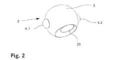
図1は、本発明による例示的な関節インプラント1を示している。関節インプラント1は、半球状のソケット4を有する第1の要素2を備える。さらに、関節10のインプラント1は、ボールヘッド5を含む第2の要素3を備える。ボールヘッド5は、ソケット4内に配置され、したがってボールソケット連結を形成する。示された例示的な実施形態においては、第2の要素3は、ボールヘッド5、ならびに、たとえばねじ山を含む穴の形の結合部20を備える。あるいは、結合部20は、モールステーパーとして構成され得る。シャフトまたはステムなどのさらなるコンポーネントは、結合部20によって第2の要素3と結合され得る。示された実施形態においては、ボールヘッド5は、ドームの形で設けられる。 FIG. 1 shows an exemplary
半球状のソケット4は、前記ボールヘッド5に設けられる2つの突出部6.1,6.2が係合される溝7を含む。溝7ならびに突出部6.1,6.2は、合致する半球形を有する。溝7および突出部6.1,6.2を設けない場合は、ボールヘッド3は、ソケット内で3つの回転軸A1、A2、A3を中心として自由に回転することができるであろう。第1の軸A1は、図を見るとき、視野方向に平行に向けられることに留意されたい。しかし、2つの突出部6.1,6.2が溝7内に形状嵌合式に係合されるので、溝7への2つの突出部6.1,6.2の係合は、第1の軸A1を中心にボールヘッド3の回転運動を制限する。したがって、溝7内に係合される2つの突出部6.1,6.2により、1つの自由度に関節インプラント1の動き制限が生じる。示された実施形態においては、溝7は、2つの突出部6.1,6.2と同じ形状および幅を有し、したがって、第1の回転軸A1を中心とするいかなる動きも阻止される。あるいは、溝7は、2つの突出部6.1,6.2の幅よりも僅かに大きい幅を有してもよい。この種の他の実施形態においては、ボールヘッド3は、第1の回転軸A1を中心とした小さな動きを行うことができることになり、したがって、第3の回転軸A1を中心としたソケット4内のボールヘッド3の限られた「ぐらつき」を可能にする。 The
第3の回転軸A3を中心としたボールヘッド3の回転運動は、溝7内の2つの突出部6.1,6.2の摺動運動、および、溝7内の2つの突出部6.1,6.2の回転による第2の回転軸A2を中心とした回転運動によって可能にされる。 Rotational movement of the
図2は、図1による関節インプラント1の第2の要素3の詳細図を示している。2つの突出部6.1,6.2ならびにボールヘッドの形状が、この図で明確に認識され得る。お分かりのように、ボールヘッド5は、ドームの、すなわち平面で切断された球の形であるが、2つの突出部6.1,6.2は、半球体の形である。 FIG. 2 shows a detailed view of the
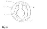
図3は、図1による関節インプラント1の第1の要素2の詳細図を示している。お分かりのように、溝7は、半球形を有し、大円に沿って半球状のソケット4に配置される。溝7は、それによってソケット4に縁部から縁部まで及ぶ。半球状のソケット4の頂点を中心として、開口部8が設けられる。 FIG. 3 shows a detailed view of the
図4は、図1による関節インプラント1の他の実施形態を示している。この実施形態は、たとえば、肩関節プロテーゼとして使用され得る。第1の要素2は、半球状のソケット4が偏心位置に配置される円形インレー9を備える。インレー9は、ベース部材10に回転可能に結合され、第4の軸A4を中心として回転する。ソケット4の溝7は、2つの突出部6.1,6.2と溝7との係合によって回転運動が阻止される第1の軸A1がインレー9の第4の回転軸A4とほぼ平行に配置されるように配置される。したがって、図4による実施形態の特定の構成によって、第3の回転軸A3のずれが実現される。 FIG. 4 shows another embodiment of the
さらに、第2の要素3は、ボールヘッド5に結合される概ねZ字形のアダプタ11を備える。アダプタ11を使って、第2の要素へのシャフトまたはステムの取り付けをずらすことが可能である。このようなずれは、肩関節プロテーゼに関して特に有利である。 Furthermore, the
図5から図7は、肩関節プロテーゼとして構成される図4による関節インプラント1を示している。プロテーゼステム12は、アダプタ11に固定される。ステム12は、患者の上腕骨に挿入されるように寸法決めされ、形成される。ボールヘッド5は、溝7(図4)によって画定される平面が、プロテーゼステム12の中心軸22(図7)を通り抜ける対称面21(図6)に対して垂直であるように、アダプタ11を介してプロテーゼステム12に連結される。他の実施形態においては、ボールヘッド5は、溝7によって画定される平面がプロテーゼステム12の中心軸22を通り抜ける対称面21に対して平行であるように、プロテーゼステム12に対して配置され得る。ベース要素10は、関節窩内に配置されるように寸法決めされ、形成されることが好ましく、その外縁は、烏口骨および肩峰と係合する。異なる構成を有する一組のアダプタ11を提供することにより、簡単な方法で異なる患者の解剖学的構造に合わせて肩関節プロテーゼインプラントをカスタマイズすることができる。 5 to 7 show the
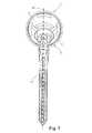
図8は、人工肘として構成される本発明の関節インプラント1を示している。第1の要素2は、患者の遠位上腕骨に移植されるように寸法決めされ、形成されるステム13、ならびに、ソケット4を備える一般的に半球状のヘッド部分14を備える。前方支持部材15は、ヘッド部分14からステム13に平行に延在し、前記前方支持部材15は、ステム13の短い部分に沿ってのみおよび、上腕骨の前方皮質と係合することを目的としている。ヘッド部分14は、ソケット4と交差する凹所16を含む。関節インプラント1の第2の要素3のボールヘッド5がソケット4に挿入され、それによって、溝7および2つの突出部6.1,6.2は、ステム13と、第2の要素3の結合部20に挿入される(図9に示される)尺骨ステムとがステム13の長手方向軸に平行な平面の外側で互いに対して移動され得ないように、ソケット4内にボールヘッド5の動きを制限する。この構成により、肘関節の自然な動きの自由を模倣する関節インプラントを提供することができる。 FIG. 8 shows the
完全な人工肘が、図9に示されている。図8に示される要素に加えて、尺骨ステム17が、ボールヘッド5に取り付けられる。凹所16の機能は、他方の方向と異なる肘の屈曲運動に対応する一方の方向に、尺骨ステム17の可動域を高めることを可能にするところが明らかになる。尺骨へのステム17の挿入の深さを制限する働きをする、追加の深さ止め18が、尺骨ステム17に配置される。 A complete artificial elbow is shown in FIG. An ulnar stem 17 is attached to the
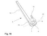
図10は、人工肘の第1の要素2をもう少し詳細に示している。お分かりように、溝7は、ソケット4の縁部から頂点まで及んでないが、縁部と頂点との間の距離の約半分で終わっている。これは、第1の軸A1を中心としたソケット4内にボールヘッド5の回転運動をさらに制限するようにする。 FIG. 10 shows the
人工肘の第2の要素3が、図11に示されている。先の例の場合のように、ボールヘッド5は、ドームの形である。しかし、この実施形態においては、ボールヘッド5は、他の半球形から突出するノーズ19を備える。ノーズ19は、結合部20によってボールヘッド5に取り付けられ得る尺骨ステム17のための追加の支持体として働く。 The
Claims (37)
Translated fromJapanesea)前記溝(7)が、前記ボールヘッド(5)の、または前記ソケット(4)の大円に沿って配置され、
b)前記突出部(6.1;6.2)が、溝(7)に収容される場合にその中心軸A2を中心として突出部の回転を可能にする形状を有し、
c)突出部(6.1;6.2)の、および/または溝(7)の表面粗さが、最大で25マイクロメートルである
ことを特徴とする、人工関節インプラント(1)。An artificial joint implant (1) comprisingonly a first element (2) having a socket (4) and a second element (3) having a ball head (5), wherein the ball head (5) is The ball head (5) in the socket (4) is insertable into the socket (4) so as to form a ball and socket connection between the first element (2) and the second element (3). ) Is limited by the projection (6.1; 6.2) engaged in the groove (7), so that said projection (6.1; 6.2) moves the central axis A2. An artificial joint implant (1) having a surface protruding from a surface of the socket (4) and wherein the groove (7) is provided on a surface of the ball head (5) or vice versa;
a) said groove (7) is arranged along a great circle of said ball head (5) or of said socket (4);
b) the projections (6.1; 6.2) have a shape that allows rotation of the projections about its central axis A2 when housed in the groove (7);
c) An artificial joint implant (1), characterized in that the surface roughness of the protrusions (6.1; 6.2) and / or of the grooves (7) is atmost 25 micrometers.
a)前記溝(7)が、前記ボールヘッド(5)の、または前記ソケット(4)の大円に沿って配置され、a) said groove (7) is arranged along a great circle of said ball head (5) or of said socket (4);
b)前記突出部(6.1;6.2)が、溝(7)に収容される場合にその中心軸A2を中心として突出部の回転を可能にする形状を有し、b) the projections (6.1; 6.2) have a shape that allows rotation of the projections about its central axis A2 when housed in the groove (7);
c)突出部(6.1;6.2)の、および/または溝(7)の表面粗さが、最大で25マイクロメートルであり、c) the surface roughness of the protrusions (6.1; 6.2) and / or of the grooves (7) is at most 25 micrometers,
d)前記第1の要素(2)が、第4の回転軸(A4)を中心としてベース部分(10)に回転可能に連結されるインレー(9)をさらに備え、前記突出部(6.1,6.2)および前記溝(7)が、第4の回転軸(A4)に対して平行な第1の回転軸(A1)を中心とした前記ボールソケット連結の自由度を少なくともブロックするように配置されるd) said first element (2) further comprises an inlay (9) rotatably connected to the base part (10) about a fourth axis of rotation (A4), said inlay (6.1) , 6.2) and the groove (7) at least block the degree of freedom of the ball and socket connection about the first rotation axis (A1) parallel to the fourth rotation axis (A4). Placed in
ことを特徴とする、人工関節インプラント(1)。An artificial joint implant (1), characterized in that:
(i)2つの突出部を通過する軸A2を中心として、および
(ii)溝が延在する大円によって定義される平面に対して直角の、および軸A2に対して直角の軸A3を中心として
回転できるようになるが、
軸A2および軸A3の両方に対して直角の軸A1を中心としたソケットの回転を防止する
ことを特徴とする、請求項1から17のいずれか一項に記載の人工関節インプラント(1)。Two projections (6.1; 6.2) are provided which are diametrically arranged with respect to each other, so that when the ball head is inserted into the socket with the two projections arranged in the groove, the ball head will have two different axes. Centered, that is,
(I) centered on axis A2 passing through the two protrusions, and (ii) centered on axis A3 perpendicular to the plane defined by the great circle in which the groove extends and perpendicular to axis A2. Will be able to rotate as
Characterized in that for both axes A2 and axis A3 to prevent rotation of the socket about the axis A1 at right angles, artificial joint implant according to any one of claims 1 to17 (1).
Applications Claiming Priority (1)
| Application Number | Priority Date | Filing Date | Title |
|---|---|---|---|
| PCT/CH2015/000058WO2016165030A1 (en) | 2015-04-15 | 2015-04-15 | Artificial joint implant |
Publications (2)
| Publication Number | Publication Date |
|---|---|
| JP2018515300A JP2018515300A (en) | 2018-06-14 |
| JP6657373B2true JP6657373B2 (en) | 2020-03-04 |
Family
ID=53016423
Family Applications (1)
| Application Number | Title | Priority Date | Filing Date |
|---|---|---|---|
| JP2018505508AActiveJP6657373B2 (en) | 2015-04-15 | 2015-04-15 | Artificial joint implant |
Country Status (7)
| Country | Link |
|---|---|
| US (1) | US10420649B2 (en) |
| EP (1) | EP3283014B1 (en) |
| JP (1) | JP6657373B2 (en) |
| CN (1) | CN107735055B (en) |
| AU (1) | AU2015390977B2 (en) |
| ES (1) | ES2747364T3 (en) |
| WO (1) | WO2016165030A1 (en) |
Families Citing this family (26)
| Publication number | Priority date | Publication date | Assignee | Title |
|---|---|---|---|---|
| WO2010121250A1 (en) | 2009-04-17 | 2010-10-21 | Arthrosurface Incorporated | Glenoid resurfacing system and method |
| US10945743B2 (en) | 2009-04-17 | 2021-03-16 | Arthrosurface Incorporated | Glenoid repair system and methods of use thereof |
| US9649194B2 (en)* | 2009-07-10 | 2017-05-16 | Peter Forsell | Hip joint device |
| FR3010628B1 (en) | 2013-09-18 | 2015-10-16 | Medicrea International | METHOD FOR REALIZING THE IDEAL CURVATURE OF A ROD OF A VERTEBRAL OSTEOSYNTHESIS EQUIPMENT FOR STRENGTHENING THE VERTEBRAL COLUMN OF A PATIENT |
| FR3012030B1 (en) | 2013-10-18 | 2015-12-25 | Medicrea International | METHOD FOR REALIZING THE IDEAL CURVATURE OF A ROD OF A VERTEBRAL OSTEOSYNTHESIS EQUIPMENT FOR STRENGTHENING THE VERTEBRAL COLUMN OF A PATIENT |
| CN107735055B (en)* | 2015-04-15 | 2020-07-24 | 41荷美沃斯股份公司 | Artificial joint implant |
| US10456211B2 (en) | 2015-11-04 | 2019-10-29 | Medicrea International | Methods and apparatus for spinal reconstructive surgery and measuring spinal length and intervertebral spacing, tension and rotation |
| WO2018109556A1 (en) | 2016-12-12 | 2018-06-21 | Medicrea International | Systems and methods for patient-specific spinal implants |
| EP3612122B1 (en) | 2017-04-21 | 2023-12-20 | Medicrea International | A system for developing one or more patient-specific spinal implants |
| EP3624736A1 (en)* | 2017-05-18 | 2020-03-25 | Smith & Nephew, Inc. | Systems and methods for determining the position and orientation of an implant for joint replacement surgery |
| US10918422B2 (en) | 2017-12-01 | 2021-02-16 | Medicrea International | Method and apparatus for inhibiting proximal junctional failure |
| CN109187219A (en)* | 2018-07-16 | 2019-01-11 | 北京强度环境研究所 | Aircraft Special-Shaped Surface structural capacity heat test roof pressing type anti-deflection loading device |
| CN109431661B (en)* | 2018-12-27 | 2024-05-28 | 北京爱康宜诚医疗器材有限公司 | Shoulder joint prosthesis |
| CN109646152A (en)* | 2018-12-29 | 2019-04-19 | 河南理工大学 | Shoulder joint prosthesis |
| WO2020186099A1 (en) | 2019-03-12 | 2020-09-17 | Arthrosurface Incorporated | Humeral and glenoid articular surface implant systems and methods |
| US11877801B2 (en) | 2019-04-02 | 2024-01-23 | Medicrea International | Systems, methods, and devices for developing patient-specific spinal implants, treatments, operations, and/or procedures |
| US11925417B2 (en) | 2019-04-02 | 2024-03-12 | Medicrea International | Systems, methods, and devices for developing patient-specific spinal implants, treatments, operations, and/or procedures |
| US11944385B2 (en) | 2019-04-02 | 2024-04-02 | Medicrea International | Systems and methods for medical image analysis |
| US11224517B2 (en)* | 2019-06-26 | 2022-01-18 | DePuy Synthes Products, Inc. | Mechanically coupled revision hip system and method |
| US11769251B2 (en) | 2019-12-26 | 2023-09-26 | Medicrea International | Systems and methods for medical image analysis |
| US11642226B2 (en)* | 2020-05-01 | 2023-05-09 | Ensemble Orthopedics, Inc. | Implantable interpositional orthopedic pain management |
| WO2021240798A1 (en)* | 2020-05-29 | 2021-12-02 | 京セラ株式会社 | Stem for artificial joint |
| CN112022448B (en)* | 2020-09-29 | 2022-09-20 | 北京市春立正达医疗器械股份有限公司 | High-mobility artificial shoulder joint prosthesis |
| CN112998914B (en)* | 2021-02-22 | 2021-10-15 | 佳木斯大学 | an artificial hip joint |
| CN113813086B (en)* | 2021-08-27 | 2024-09-06 | 重庆熙科医疗科技有限公司 | Individuation shoulder joint prosthesis and assembly method |
| CN117084832B (en)* | 2023-10-16 | 2023-12-26 | 北京爱康宜诚医疗器材有限公司 | A kind of spinal facet joint prosthesis |
Family Cites Families (33)
| Publication number | Priority date | Publication date | Assignee | Title |
|---|---|---|---|---|
| CH541962A (en)* | 1971-09-06 | 1973-09-30 | Sulzer Ag | Endo wrist prosthesis |
| US3886601A (en)* | 1972-03-04 | 1975-06-03 | Eric George Findlay | Prosthetic knee joint assembly |
| CH592445A5 (en) | 1975-06-17 | 1977-10-31 | Sulzer Ag | |
| US4040130A (en)* | 1976-10-12 | 1977-08-09 | Laure Prosthetics, Inc. | Wrist joint prosthesis |
| US4106128A (en)* | 1976-12-06 | 1978-08-15 | Greenwald A Seth | Endoprosthetic bone joint |
| DE2829676A1 (en)* | 1978-07-06 | 1980-01-24 | Gmt Medizinische Technik Gmbh | ENDOPROTHESIS |
| US4642123A (en)* | 1983-03-08 | 1987-02-10 | Joint Medical Products Corporation | Ball and socket bearing for artificial joint |
| US4950299A (en)* | 1983-03-08 | 1990-08-21 | Joint Medical Products Corporation | Ball and socket bearing for artificial joint |
| US4978356A (en)* | 1983-03-08 | 1990-12-18 | Joint Medical Products Corporation | Ball and socket bearing for artificial joint |
| US4960427A (en)* | 1983-03-08 | 1990-10-02 | Joint Medical Products Corporation | Ball and socket bearing for artifical joint |
| US5007932A (en)* | 1985-01-08 | 1991-04-16 | Ngk Spark Plug Co., Ltd. | Artificial bone joint |
| FR2691357A1 (en)* | 1992-05-25 | 1993-11-26 | Tornier Sa | Total prosthesis for the metacarpophalangeal joint. |
| US20020143402A1 (en) | 1995-09-04 | 2002-10-03 | Limber Ltd. | Hip joint prostheses |
| JP2002503999A (en)* | 1997-06-18 | 2002-02-05 | ベーラー,アンドレ | Endoprosthesis for joints, especially finger, toe or wrist joints |
| US6454808B1 (en)* | 1998-01-28 | 2002-09-24 | M-E-System Inc. | Finger joint prosthesis |
| US5938700A (en)* | 1998-02-11 | 1999-08-17 | Engineering Consulting Services, Inc. | Constrained prosthesis for replacement of joints between long bones in the hand |
| AUPQ282099A0 (en)* | 1999-09-14 | 1999-10-07 | Krishnan, Jeganath | Metacarpo phalangeal joint prosthesis |
| US10231839B2 (en)* | 2000-07-18 | 2019-03-19 | Encore Medical, L.P. | Elbow prosthesis |
| US6660040B2 (en)* | 2001-12-19 | 2003-12-09 | Depuy Orthopaedics, Inc. | Prosthetic joints having reduced area bearing surfaces and application thereof to a range of sizes of prosthetic joints |
| US6770095B2 (en)* | 2002-06-18 | 2004-08-03 | Depuy Acroned, Inc. | Intervertebral disc |
| FR2846550B1 (en)* | 2002-11-05 | 2006-01-13 | Ldr Medical | INTERVERTEBRAL DISC PROSTHESIS |
| US7108720B2 (en)* | 2003-03-31 | 2006-09-19 | Depuy Products, Inc. | Reduced wear orthopaedic implant apparatus and method |
| US7811329B2 (en)* | 2003-07-31 | 2010-10-12 | Globus Medical | Transforaminal prosthetic spinal disc replacement and methods thereof |
| JP2007505669A (en)* | 2003-09-19 | 2007-03-15 | エレメント シックス リミテッド | Artificial joint |
| PL2057971T3 (en)* | 2007-11-07 | 2010-10-29 | Gs Dev Ab | Artificial joint |
| CA2754581C (en)* | 2009-03-11 | 2016-06-07 | Exactech, Inc. | Motion inducing reverse shoulder assembly |
| US9649194B2 (en)* | 2009-07-10 | 2017-05-16 | Peter Forsell | Hip joint device |
| US8313531B2 (en)* | 2010-03-08 | 2012-11-20 | Hip Innovation Technology Llc | Interlocking reverse hip prosthesis and method |
| US20120004733A1 (en)* | 2010-06-30 | 2012-01-05 | Hodorek Brian C | Modular articulating prostheses and associated methods |
| US8771366B2 (en)* | 2012-03-30 | 2014-07-08 | DePuy Synthes Products, LLC | Mobile bearing hip assembly having decoupled motion along multiple axes |
| US8858645B2 (en)* | 2012-06-21 | 2014-10-14 | DePuy Synthes Products, LLC | Constrained mobile bearing hip assembly |
| PL3054896T3 (en)* | 2013-10-13 | 2018-02-28 | 41Hemiverse Ag | Joint implant |
| CN107735055B (en)* | 2015-04-15 | 2020-07-24 | 41荷美沃斯股份公司 | Artificial joint implant |
- 2015
- 2015-04-15CNCN201580080893.8Apatent/CN107735055B/enactiveActive
- 2015-04-15JPJP2018505508Apatent/JP6657373B2/enactiveActive
- 2015-04-15ESES15719405Tpatent/ES2747364T3/enactiveActive
- 2015-04-15AUAU2015390977Apatent/AU2015390977B2/enactiveActive
- 2015-04-15EPEP15719405.1Apatent/EP3283014B1/enactiveActive
- 2015-04-15USUS15/565,456patent/US10420649B2/enactiveActive
- 2015-04-15WOPCT/CH2015/000058patent/WO2016165030A1/ennot_activeCeased
Also Published As
| Publication number | Publication date |
|---|---|
| US10420649B2 (en) | 2019-09-24 |
| US20180116808A1 (en) | 2018-05-03 |
| CN107735055B (en) | 2020-07-24 |
| JP2018515300A (en) | 2018-06-14 |
| EP3283014B1 (en) | 2019-08-07 |
| AU2015390977A1 (en) | 2017-10-26 |
| AU2015390977B2 (en) | 2020-05-14 |
| CN107735055A (en) | 2018-02-23 |
| AU2015390977A8 (en) | 2017-11-09 |
| WO2016165030A1 (en) | 2016-10-20 |
| ES2747364T3 (en) | 2020-03-10 |
| EP3283014A1 (en) | 2018-02-21 |
Similar Documents
| Publication | Publication Date | Title |
|---|---|---|
| JP6657373B2 (en) | Artificial joint implant | |
| US20220338997A1 (en) | Modular Rotational Device For Torsionally Stabilizing An Endoprosthesis | |
| JP6434037B2 (en) | Joint implant | |
| US9119724B2 (en) | Interlocking reverse hip revision prosthesis | |
| JP6141113B2 (en) | Constrained movable bearing hip assembly | |
| EP3308746B1 (en) | Mobile bearing hip assembly having decoupled motion along multiple axes | |
| EP3838231A1 (en) | Component for a joint replacement | |
| WO2012051552A2 (en) | Modular humeral prosthesis with spherocentric feature | |
| WO2019069332A1 (en) | Improved prosthesis component, so-called liner, for an acetabular or glenoid cup |
Legal Events
| Date | Code | Title | Description |
|---|---|---|---|
| A621 | Written request for application examination | Free format text:JAPANESE INTERMEDIATE CODE: A621 Effective date:20180327 | |
| A977 | Report on retrieval | Free format text:JAPANESE INTERMEDIATE CODE: A971007 Effective date:20190131 | |
| A131 | Notification of reasons for refusal | Free format text:JAPANESE INTERMEDIATE CODE: A131 Effective date:20190205 | |
| A601 | Written request for extension of time | Free format text:JAPANESE INTERMEDIATE CODE: A601 Effective date:20190425 | |
| A521 | Request for written amendment filed | Free format text:JAPANESE INTERMEDIATE CODE: A523 Effective date:20190703 | |
| TRDD | Decision of grant or rejection written | ||
| A01 | Written decision to grant a patent or to grant a registration (utility model) | Free format text:JAPANESE INTERMEDIATE CODE: A01 Effective date:20200107 | |
| A61 | First payment of annual fees (during grant procedure) | Free format text:JAPANESE INTERMEDIATE CODE: A61 Effective date:20200205 | |
| R150 | Certificate of patent or registration of utility model | Ref document number:6657373 Country of ref document:JP Free format text:JAPANESE INTERMEDIATE CODE: R150 | |
| R250 | Receipt of annual fees | Free format text:JAPANESE INTERMEDIATE CODE: R250 | |
| R250 | Receipt of annual fees | Free format text:JAPANESE INTERMEDIATE CODE: R250 | |
| R250 | Receipt of annual fees | Free format text:JAPANESE INTERMEDIATE CODE: R250 |