JP6654883B2 - Surgical system, manipulator arm, and manipulator arm support - Google Patents
Surgical system, manipulator arm, and manipulator arm supportDownload PDFInfo
- Publication number
- JP6654883B2 JP6654883B2JP2015242698AJP2015242698AJP6654883B2JP 6654883 B2JP6654883 B2JP 6654883B2JP 2015242698 AJP2015242698 AJP 2015242698AJP 2015242698 AJP2015242698 AJP 2015242698AJP 6654883 B2JP6654883 B2JP 6654883B2
- Authority
- JP
- Japan
- Prior art keywords
- arm
- platform
- information
- manipulator arm
- manipulator
- Prior art date
- Legal status (The legal status is an assumption and is not a legal conclusion. Google has not performed a legal analysis and makes no representation as to the accuracy of the status listed.)
- Active
Links
Images


Classifications
- A—HUMAN NECESSITIES
- A61—MEDICAL OR VETERINARY SCIENCE; HYGIENE
- A61B—DIAGNOSIS; SURGERY; IDENTIFICATION
- A61B34/00—Computer-aided surgery; Manipulators or robots specially adapted for use in surgery
- A61B34/30—Surgical robots
- A61B34/37—Leader-follower robots
- A—HUMAN NECESSITIES
- A61—MEDICAL OR VETERINARY SCIENCE; HYGIENE
- A61B—DIAGNOSIS; SURGERY; IDENTIFICATION
- A61B34/00—Computer-aided surgery; Manipulators or robots specially adapted for use in surgery
- A61B34/30—Surgical robots
- A61B34/35—Surgical robots for telesurgery
- A—HUMAN NECESSITIES
- A61—MEDICAL OR VETERINARY SCIENCE; HYGIENE
- A61B—DIAGNOSIS; SURGERY; IDENTIFICATION
- A61B17/00—Surgical instruments, devices or methods
- A61B17/28—Surgical forceps
- A61B17/29—Forceps for use in minimally invasive surgery
- A61B17/295—Forceps for use in minimally invasive surgery combined with cutting implements
- A—HUMAN NECESSITIES
- A61—MEDICAL OR VETERINARY SCIENCE; HYGIENE
- A61B—DIAGNOSIS; SURGERY; IDENTIFICATION
- A61B34/00—Computer-aided surgery; Manipulators or robots specially adapted for use in surgery
- A61B34/70—Manipulators specially adapted for use in surgery
- A—HUMAN NECESSITIES
- A61—MEDICAL OR VETERINARY SCIENCE; HYGIENE
- A61B—DIAGNOSIS; SURGERY; IDENTIFICATION
- A61B50/00—Containers, covers, furniture or holders specially adapted for surgical or diagnostic appliances or instruments, e.g. sterile covers
- A61B50/20—Holders specially adapted for surgical or diagnostic appliances or instruments
- A—HUMAN NECESSITIES
- A61—MEDICAL OR VETERINARY SCIENCE; HYGIENE
- A61B—DIAGNOSIS; SURGERY; IDENTIFICATION
- A61B90/00—Instruments, implements or accessories specially adapted for surgery or diagnosis and not covered by any of the groups A61B1/00 - A61B50/00, e.g. for luxation treatment or for protecting wound edges
- A61B90/90—Identification means for patients or instruments, e.g. tags
- B—PERFORMING OPERATIONS; TRANSPORTING
- B25—HAND TOOLS; PORTABLE POWER-DRIVEN TOOLS; MANIPULATORS
- B25J—MANIPULATORS; CHAMBERS PROVIDED WITH MANIPULATION DEVICES
- B25J9/00—Programme-controlled manipulators
- B25J9/06—Programme-controlled manipulators characterised by multi-articulated arms
- B—PERFORMING OPERATIONS; TRANSPORTING
- B25—HAND TOOLS; PORTABLE POWER-DRIVEN TOOLS; MANIPULATORS
- B25J—MANIPULATORS; CHAMBERS PROVIDED WITH MANIPULATION DEVICES
- B25J9/00—Programme-controlled manipulators
- B25J9/08—Programme-controlled manipulators characterised by modular constructions
- A—HUMAN NECESSITIES
- A61—MEDICAL OR VETERINARY SCIENCE; HYGIENE
- A61B—DIAGNOSIS; SURGERY; IDENTIFICATION
- A61B17/00—Surgical instruments, devices or methods
- A61B2017/00017—Electrical control of surgical instruments
- A61B2017/00115—Electrical control of surgical instruments with audible or visual output
- A61B2017/00119—Electrical control of surgical instruments with audible or visual output alarm; indicating an abnormal situation
- A—HUMAN NECESSITIES
- A61—MEDICAL OR VETERINARY SCIENCE; HYGIENE
- A61B—DIAGNOSIS; SURGERY; IDENTIFICATION
- A61B17/00—Surgical instruments, devices or methods
- A61B2017/00477—Coupling
- A—HUMAN NECESSITIES
- A61—MEDICAL OR VETERINARY SCIENCE; HYGIENE
- A61B—DIAGNOSIS; SURGERY; IDENTIFICATION
- A61B90/00—Instruments, implements or accessories specially adapted for surgery or diagnosis and not covered by any of the groups A61B1/00 - A61B50/00, e.g. for luxation treatment or for protecting wound edges
- A61B90/08—Accessories or related features not otherwise provided for
- A61B2090/0803—Counting the number of times an instrument is used
- B—PERFORMING OPERATIONS; TRANSPORTING
- B25—HAND TOOLS; PORTABLE POWER-DRIVEN TOOLS; MANIPULATORS
- B25J—MANIPULATORS; CHAMBERS PROVIDED WITH MANIPULATION DEVICES
- B25J9/00—Programme-controlled manipulators
- B25J9/0009—Constructional details, e.g. manipulator supports, bases
Landscapes
- Health & Medical Sciences (AREA)
- Engineering & Computer Science (AREA)
- Life Sciences & Earth Sciences (AREA)
- Surgery (AREA)
- Robotics (AREA)
- Animal Behavior & Ethology (AREA)
- Public Health (AREA)
- Heart & Thoracic Surgery (AREA)
- Medical Informatics (AREA)
- Molecular Biology (AREA)
- Nuclear Medicine, Radiotherapy & Molecular Imaging (AREA)
- General Health & Medical Sciences (AREA)
- Biomedical Technology (AREA)
- Veterinary Medicine (AREA)
- Mechanical Engineering (AREA)
- Oral & Maxillofacial Surgery (AREA)
- Pathology (AREA)
- Ophthalmology & Optometry (AREA)
- Manipulator (AREA)
- Endoscopes (AREA)
Description
Translated fromJapanese本発明は、外科手術を行うためのインストゥルメントが取り付けられるマニピュレータアーム、マニピュレータアーム支持体、及び、これらを含む外科手術システムに関する。 The present invention relates to a manipulator arm to which an instrument for performing a surgical operation is mounted, a manipulator arm support, and a surgical operation system including the same.
従来、ロボット支援外科手術や遠隔ロボット外科手術などの、マニピュレータを含む外科手術システムを利用する外科手術が知られている。このシステムは、鉗子やメスなどの手術器具や内視鏡カメラなどのインストゥルメントと、このインストゥルメントを先端部に装着したマニピュレータアームとを備え、術者は患者から離れた場所に設置された操作装置を用いてマニピュレータアーム及びインストゥルメントの動作を遠隔操作して、患者の手術部位に施術する。特許文献1及び特許文献2には、この種の外科手術システムが開示されている。 2. Description of the Related Art Conventionally, a surgical operation using a surgical operation system including a manipulator, such as a robot assisted surgical operation and a remote robot surgical operation, is known. This system includes instruments such as surgical instruments such as forceps and a scalpel and an endoscope camera, and a manipulator arm with the instrument attached to the distal end. The operation of the manipulator arm and the instrument is remotely controlled using the operating device, and the operation is performed on the surgical site of the patient.
特許文献1に示された外科手術システム(ロボット手術システム)は、プラットホームと、プラットホームに連結された複数のセットアップアームと、各セットアップアームの遠位端部に連結されたマニピュレータベースと、マニピュレータベースに連結されたマニピュレータと、マニピュレータの遠位端部に取り付けられた手術器具とを備えている。プラットホームは、手術室の天井に設けられたプラットホームリンケージを介して、手術室の天井に上下昇降可能に吊設されている。 The surgical operation system (robot operation system) disclosed in
また、特許文献2には、滅菌野において外科手術を行うための外科手術用ロボットシステムが示されている。このロボットシステムは、ロボットアームと、ロボットアームの遠位端部に設けられたリストユニットと、リストユニットに着脱可能に取り付けられた手術器具とを備えている。ロボットアームの駆動アセンブリは当該ロボットアームの近位端部に設けられており、この駆動アセンブリは取付ブラケットに収容されている。この取付ブラケットは、手術台の側方に設けられたレールを走行可能な取付アームに支持された取付ジョイントと接続される。そして、ロボットアームとリストユニットは、滅菌野からこれらの非滅菌部分を遮蔽する滅菌ドレープで覆われている。
上記特許文献1の構成において、複数のセットアップアームが設けられており、各セットアップアームに1本のマニピュレータが支持されている。また、特許文献2の構成において、手術台に複数の取付ジョイントが設けられており、各取付ジョイントに1本のロボットアームの取付ブラケットが取り付けられている。特許文献1,2の構成において、インストゥルメントはマニピュレータ(又はロボットアーム)から着脱自在であるが、マニピュレータ(又はロボットアーム)はセットアップアーム(又は、取付ブラケット)から容易に離脱できないように結合されている。 In the configuration of
ところで、手術の種類や内容に応じて、手術中に使用されるインストゥルメントの数や、種類、組合せなどが異なる。例えば、手術中に同時に使用されるインストゥルメントが、3個又は3種類以上の場合もあれば、2個又は2種類の場合もある。前者では、内視鏡カメラが取り付けられるマニピュレータアームを含めて少なくとも4本以上のマニピュレータアームが必要であるが、後者では3本のマニピュレータアームで足りる。従って、後者の場合には、手術中に使用されないマニピュレータアームが生じることがある。また、例えば、手術の内容(患部の位置)によっては、外科手術システムが具備する複数のマニピュレータアームに長短の違いが要求されることがある。 By the way, the number, types, combinations, etc. of instruments used during the operation differ depending on the type and content of the operation. For example, there may be three or more instruments used simultaneously during surgery, or two or two instruments. In the former, at least four or more manipulator arms including the manipulator arm to which the endoscope camera is attached are required, while in the latter, three manipulator arms are sufficient. Thus, in the latter case, there may be manipulator arms that are not used during the operation. Further, for example, depending on the content of the operation (position of the affected part), a difference in length between a plurality of manipulator arms provided in the surgical operation system may be required.
上記事情に鑑み、発明者らは、マニピュレータを含む外科手術システムにおいて、マニピュレータアームの数や種類、組合せなどを、手術前に及び/又は手術中にカスタマイズすることに想到した。これにより、個々の手術に適切な外科手術システムの構築が可能となる。 In view of the above circumstances, the present inventors have reached the idea of customizing the number, type, combination, and the like of manipulator arms before and / or during surgery in a surgical operation system including a manipulator. This makes it possible to construct a surgical operation system appropriate for each operation.
そこで、本発明ではマニピュレータを含む外科手術システムにおいて、手術前及び/又は手術中に、インストゥルメントを支持するマニピュレータアームの構成を手術の内容に応じて容易にカスタマイズする技術を提案する。 In view of the above, the present invention proposes a technique for easily customizing the configuration of a manipulator arm supporting an instrument in a surgical operation system including a manipulator before and / or during an operation according to the contents of the operation.
本発明の一態様に係る外科手術システムは、
外科手術を行うための複数のインストゥルメントと、
プラットホームと、
前記プラットホームに基端部が着脱可能に取り付けられる複数のマニピュレータアームであって、各マニピュレータアームの先端部に前記複数のインストゥルメントのうちの一つが着脱可能に取り付けられて当該インストゥルメントを移動可能に支持する複数のマニピュレータアームと、
前記プラットホームに取り付けられた各マニピュレータアームの取付ロック及び取付ロック解除が可能な取付ロック機構と、
前記プラットホームに取り付けられた前記マニピュレータアームの有無を検出する検出センサと、
前記プラットホームに設けられた、前記マニピュレータアームが保有する情報を読み出すリーダーと、
前記プラットホームに取り付けられた前記マニピュレータアームを管理する管理装置とを備え、
前記管理装置は、前記検出センサからの検出信号に基づいて前記プラットホームに前記マニピュレータアームが取り付けられたことを検知し、前記プラットホームに前記マニピュレータアームが取り付けられたことが検知されると前記リーダーに前記情報の読み出し動作をさせ、前記リーダーが読み出した前記情報を取得し、取得した情報を前記プラットホーム上の取付位置情報に関連付けて一時的に記憶することを特徴としている。
A surgical operation system according to one embodiment of the present invention includes:
Multiple instruments for performing surgery,
Platform and
A plurality of manipulator arms having a base end detachably attached to the platform, wherein one of the plurality of instruments is detachably attached to a distal end of each manipulator arm to move the instrument; A plurality of manipulator arms for supporting as possible;
A mounting lock mechanism capable of mounting and releasing the mounting lock of each manipulator arm mounted on the platform,
A detection sensor for detecting the presence or absence of the manipulator arm attached to the platform;
A reader provided on the platform, for reading information held by the manipulator arm;
A management device for managing the manipulator arm attached to the platform,
The management device detects that the manipulator arm is attached to the platform based on a detection signal from the detection sensor, and when it is detected that the manipulator arm is attached to the platform, the reader sends the manipulator arm to the reader. is a read operation of the information to obtain the said information reader read is characterized thatyou temporarily stored in association with the information acquired in the mounting position information on the platform.
上記外科手術システムでは、プラットホームにマニピュレータアームを配置して取付ロック機構(支持体側係合部、アーム側係合部)で取付ロックすることにより、プラットホームにマニピュレータアームを取り付けることができる。また、プラットホームに取り付けられたマニピュレータアームの取付ロックを解除することにより、プラットホームからマニピュレータアームを取り外すことができる。このように、プラットホームに対しマニピュレータアームが着脱自在であり、手術前及び/又は手術中に、プラットホームに取り付けられているマニピュレータアームを交換したり、プラットホームの或る取付位置に取り付けられているマニピュレータアームを他の取付位置に付け替えたりすることができる。このように、手術前及び/又は手術中に、手術の内容に応じた数、種類、組合せのマニピュレータアームをプラットホームに取り付けることによって、システムをその手術に適切にカスタマイズすることができる。
In the above surgical operation system, the manipulator arm can be attached to the platform by arranging the manipulator arm on the platform and attaching and locking the manipulator arm with the attachment lock mechanism (support-side engaging portion, arm-side engaging portion). Further, by releasing the attachment lock of the manipulator arm attached to the platform, the manipulator arm can be removed from the platform. As described above, the manipulator arm is detachable from the platform, and the manipulator arm attached to the platform can be replaced before and / or during the operation, or the manipulator arm attached to a certain mounting position on the platform. Can be replaced with another mounting position. Thus, before and / or during the operation, the system can be appropriately customized for the operation by attaching the number, type, and combination of manipulator arms according to the contents of the operation to the platform.
本発明によれば、マニピュレータを含む外科手術システムにおいて、手術前及び/又は手術中に、インストゥルメントを支持するマニピュレータアームの構成を手術の内容に応じて容易にカスタマイズする技術を提案することができる。 According to the present invention, in a surgical operation system including a manipulator, it is possible to propose a technique for easily customizing the configuration of a manipulator arm supporting an instrument according to the contents of an operation before and / or during an operation. it can.
以下に説明する本発明の一実施形態に係る外科手術システムは、外科手術を行うための複数のインストゥルメントと、プラットホームと、前記プラットホームに基端部が着脱可能に取り付けられる複数のマニピュレータアームであって、各マニピュレータアームの先端部に前記複数のインストゥルメントのうちの一つが着脱可能に取り付けられて当該インストゥルメントを移動可能に支持する複数のマニピュレータアームと、前記プラットホームに取り付けられた各マニピュレータアームの取付ロック及び取付ロック解除が可能な取付ロック機構とを、備えることを特徴としている。 A surgical operation system according to an embodiment of the present invention described below includes a plurality of instruments for performing a surgical operation, a platform, and a plurality of manipulator arms whose base ends are detachably attached to the platform. A plurality of manipulator arms, one of the plurality of instruments being detachably attached to a distal end portion of each manipulator arm to movably support the instrument, and each of the plurality of manipulator arms attached to the platform. And a mounting lock mechanism capable of mounting and releasing the mounting lock of the manipulator arm.
上記外科手術システムにおいて、前記プラットホームは、前記複数のマニピュレータアームの数以上の数のマニピュレータアーム取付部を有していてよい。 In the above-mentioned surgical operation system, the platform may include manipulator arm mounting portions equal to or more than the number of the plurality of manipulator arms.
上記外科手術システムは、前記プラットホームを移動可能に支持するポジショナを、更に備えていてよい。 The surgical system may further include a positioner that movably supports the platform.
上記外科手術システムは、前記プラットホームに取り付けられた前記マニピュレータアームの有無を検出する検出センサと、前記検出センサからの検出信号に基づいて、前記プラットホームに前記マニピュレータアームが取り付けられたことを検知する管理装置とを、更に備えていてよい。 The surgical operation system includes a detection sensor that detects the presence or absence of the manipulator arm attached to the platform, and management that detects that the manipulator arm is attached to the platform based on a detection signal from the detection sensor. And a device.
上記外科手術システムにおいて、前記プラットホームに前記マニピュレータアームが保有する情報を読み出すリーダーが設けられており、前記管理装置は、前記プラットホームに前記マニピュレータアームが取り付けられたことを検知すると、前記リーダーに前記情報の読み出し動作をさせ、前記リーダーが読み出した前記情報を取得し、取得した情報を前記プラットホーム上の取付位置に関連付けて一時的に記憶するように構成されていてよい。 In the surgical operation system, the platform is provided with a reader that reads information held by the manipulator arm.When the management device detects that the manipulator arm is attached to the platform, the management device reads the information. , The information read by the reader may be acquired, and the acquired information may be temporarily stored in association with the mounting position on the platform.
上記外科手術システムにおいて、前記マニピュレータアームが保有する前記情報に、当該マニピュレータアームの個体識別情報が含まれており、前記管理装置に、手術で使用される複数のマニピュレータアームの組合せを含む手術情報が予め設定されており、前記管理装置は、前記リーダーから取得した情報に含まれる個体識別情報の組合せが前記手術情報と対応しなければ警告を出力するように構成されていてよい。 In the surgical operation system, the information held by the manipulator arm includes individual identification information of the manipulator arm, and the management device includes surgery information including a combination of a plurality of manipulator arms used in surgery. The management device may be configured in advance and output a warning if the combination of the individual identification information included in the information acquired from the reader does not correspond to the surgery information.
上記外科手術システムにおいて、前記マニピュレータアームが保有する前記情報に、当該マニピュレータアームの個体識別情報が含まれており、前記管理装置に、手術で使用されるマニピュレータアームの個体識別情報と当該マニピュレータアームが取り付けられるべき前記プラットホーム上の取付位置との組合せを含む手術情報が予め設定されており、
前記管理装置は、前記リーダーから取得した情報に含まれる個体識別情報と前記プラットホーム上の取付位置との組合せが前記手術情報と対応しなければ警告を出力するように構成されていてよい。In the surgical operation system, the information held by the manipulator arm includes individual identification information of the manipulator arm, and the management device includes individual identification information of a manipulator arm used in surgery and the manipulator arm. Surgical information including a combination with the mounting position on the platform to be mounted is preset,
The management device may be configured to output a warning if a combination of the individual identification information included in the information acquired from the reader and the mounting position on the platform does not correspond to the surgical information.
上記外科手術システムにおいて、前記マニピュレータアームが保有する前記情報に、前記マニピュレータアームの型番情報が含まれており、前記管理装置に、手術で使用されるマニピュレータアームの型番情報と当該マニピュレータアームが取り付けられるべき前記プラットホーム上の取付位置との組合せを含む手術情報が予め設定されており、前記管理装置は、前記リーダーから取得した情報に含まれる型番情報と前記プラットホーム上の取付位置との組合せが前記手術情報と対応しなければ警告を出力するように構成されていてよい。 In the surgical operation system, the information held by the manipulator arm includes model number information of the manipulator arm, and the management device is attached with the model number information of a manipulator arm used in a surgery and the manipulator arm. Surgical information including a combination with the mounting position on the platform to be set is set in advance, and the management device determines that the combination of the model number information included in the information obtained from the reader and the mounting position on the platform is the surgical operation. If it does not correspond to the information, a warning may be output.
上記外科手術システムにおいて、前記マニピュレータアームが保有する前記情報に、前記マニピュレータアームの個体識別情報が含まれており、前記管理装置に、手術で使用されるマニピュレータアームの型番情報と当該マニピュレータアームが取り付けられるべき前記プラットホーム上の取付位置との組合せを含む手術情報が予め設定されており、前記管理装置は、個体識別情報に関連付けられたマニピュレータアームの型番情報を記憶した型番記憶部を有し、前記リーダーから取得した情報に含まれる個体識別情報に基づいて前記型番記憶部から対応する型番情報を読み出し、読み出した型番情報と前記プラットホーム上の取付位置の組合せが前記手術情報と対応しなければ警告を出力するように構成されていてよい。 In the above surgical operation system, the information held by the manipulator arm includes individual identification information of the manipulator arm, and the management device is attached with the model number information of the manipulator arm used in surgery and the manipulator arm. Surgical information including a combination with an attachment position on the platform to be performed is set in advance, and the management device has a model number storage unit that stores model number information of a manipulator arm associated with individual identification information, The corresponding model number information is read from the model number storage unit based on the individual identification information included in the information obtained from the reader, and a warning is issued if the combination of the read model number information and the mounting position on the platform does not correspond to the surgical information. It may be configured to output.
上記外科手術システムにおいて、前記マニピュレータアームの保有する前記情報に当該マニピュレータアームの個体識別情報及び使用回数情報が含まれており、前記管理装置は、前記個体識別情報に関連づけられた使用制限回数を記憶した使用制限回数記憶部を有し、前記リーダーから取得した情報に含まれる個体識別情報に基づいて前記使用制限回数記憶部から前記マニピュレータアームの使用制限回数を読み出し、前記リーダーから取得した情報に含まれる使用回数情報が前記使用制限回数を超えていれば警告を出力するように構成されていてよい。 In the above-mentioned surgical operation system, the information held by the manipulator arm includes the individual identification information and the number of times of use of the manipulator arm, and the management device stores a use limit number associated with the individual identification information. Use limit number storage unit, read the use limit number of the manipulator arm from the use limit number storage unit based on the individual identification information included in the information obtained from the reader, included in the information obtained from the reader If the usage count information exceeds the usage limit count, a warning may be output.
上記外科手術システムにおいて、前記マニピュレータアームが保有する前記情報は当該マニピュレータアームに設けられたICタグに記憶されており、前記リーダーは前記ICタグへの書き込み機能を有し、前記管理装置は、前記リーダーから取得した使用回数情報に1を加えた新たな使用回数情報を前記ICタグへ書き込むように前記リーダーを動作させるように構成されていてよい。 In the surgical operation system, the information held by the manipulator arm is stored in an IC tag provided on the manipulator arm, the reader has a function of writing to the IC tag, and the management device includes The reader may be configured to operate so that new usage count information obtained by adding 1 to the usage count information acquired from the reader is written to the IC tag.
上記外科手術システムにおいて、前記プラットホームに当該プラットホーム内に挿通された電線又は通信配線のソケットが設けられており、前記マニピュレータアームの前記基端部において当該マニピュレータアームが前記プラットホームに取り付けられたときに前記ソケットと接続される位置に、当該マニピュレータアームの電線又は通信配線と接続されたコネクタが設けられていてよい。 In the above-mentioned surgical operation system, the platform is provided with a socket of an electric wire or a communication wire inserted into the platform, and the manipulator arm is attached to the platform at the base end of the manipulator arm. A connector connected to the electric wire or communication wire of the manipulator arm may be provided at a position connected to the socket.
上記外科手術システムにおいて、前記プラットホームにモータが設けられており、前記マニピュレータアームの前記基端部に当該マニピュレータアームの動力系統への入力軸が設けられており、前記プラットホームに前記マニピュレータアームの前記基端部を取り付けたときに前記モータの出力軸と前記入力軸とを動力伝達可能に接続する軸継手が前記出力軸の端部と前記入力軸の端部とに設けられていてよい。 In the above surgical operation system, a motor is provided on the platform, an input shaft to a power system of the manipulator arm is provided at the base end of the manipulator arm, and the platform of the manipulator arm is provided on the platform. A shaft joint that connects the output shaft of the motor and the input shaft so that power can be transmitted when an end is attached may be provided at an end of the output shaft and an end of the input shaft.
上記外科手術システムにおいて、前記プラットホーム、前記マニピュレータアーム、及び前記インストゥルメントが滅菌野に設置されており、これらのうち前記プラットホームが滅菌ドレープによって前記滅菌野から遮蔽されていてよい。 In the above surgical system, the platform, the manipulator arm, and the instrument may be installed in a sterile field, and the platform may be shielded from the sterile field by a sterile drape.
また、以下に説明する本発明の一実施形態に係るマニピュレータアームは、支持体に取り付けられ、外科手術を行うためのインストゥルメントが先端部に取り付けられるマニピュレータアームであって、ベースと、前記ベースに直列的に連結された少なくとも1つのリンクと、前記ベースの基端部に設けられ、前記支持体に設けられた支持体側係合部と係合可能なアーム側係合部を有するインターフェース部とを備え、前記支持体側係合部と前記アーム側係合部の係合によって前記インターフェース部が前記支持体に取り付けられた状態でロックされ、前記支持体側係合部と前記アーム側係合部の係合解除によって前記インターフェース部が前記支持体から離脱できるように前記ロックが解除されることを特徴としている。 Further, a manipulator arm according to an embodiment of the present invention described below is a manipulator arm attached to a support, and an instrument for performing a surgical operation is attached to a distal end portion, the base, the base, the base At least one link serially connected to the base, and an interface provided at a base end of the base and having an arm-side engaging portion engageable with a support-side engaging portion provided on the support. The interface portion is locked in a state where the interface portion is attached to the support by the engagement between the support-side engagement portion and the arm-side engagement portion, and the interface portion is locked between the support-side engagement portion and the arm-side engagement portion. The lock is released so that the interface can be detached from the support by releasing the engagement.
上記マニピュレータアームは、前記支持体側に設けられたリーダーが読取可能な情報を保有していてよい。 The manipulator arm may have information readable by a reader provided on the support side.
上記マニピュレータアームにおいて、前記情報が個体識別情報であってよい。 In the manipulator arm, the information may be individual identification information.
上記マニピュレータアームにおいて、前記情報が型番情報であってよい。 In the manipulator arm, the information may be model number information.
上記マニピュレータアームにおいて、前記情報が個体識別情報及び使用回数情報であってよい。 In the manipulator arm, the information may be individual identification information and use count information.
上記マニピュレータアームにおいて、前記情報は前記インターフェース部に設けられたICタグに記憶されていてよい。 In the manipulator arm, the information may be stored in an IC tag provided in the interface unit.
上記マニピュレータアームにおいて、前記インターフェース部に、前記支持体を通された配線と前記マニピュレータアームを通された配線とを接続するコネクタが設けられていてよい。 In the above-mentioned manipulator arm, the interface part may be provided with a connector for connecting a wire passed through the support and a wire passed through the manipulator arm.
上記マニピュレータアームにおいて、前記インターフェース部に、前記支持体に設けられた動力源から入力を受け付ける入力部が設けられていてよい。 In the above-mentioned manipulator arm, the interface unit may be provided with an input unit that receives an input from a power source provided on the support.
また、以下に説明する本発明の一実施形態に係るマニピュレータアーム支持体は、外科手術を行うためのインストゥルメントを移動可能に支持するマニピュレータアームが取り付けられるプラットホームと、前記プラットホームを移動可能に支持するポジショナとを備え、前記プラットホームは、前記マニピュレータアームが着脱可能に取り付けられる複数のアーム取付部と、前記マニピュレータアームに設けられたアーム側係合部と係合可能な支持体側係合部とを有し、前記支持体側係合部と前記アーム側係合部の係合によって前記マニピュレータアームが前記アーム取付部に取り付けられた状態でロックされ、前記支持体側係合部と前記アーム側係合部の係合解除によって前記マニピュレータアームが前記アーム取付部から離脱できるように前記ロックが解除されることを特徴としている。
以下、図面を参照しながら、上記外科手術システム及び上記マニピュレータアームについて詳細に説明する。In addition, a manipulator arm support according to an embodiment of the present invention described below includes a platform on which a manipulator arm for movably supporting an instrument for performing a surgical operation is mounted, and a movably supporting platform. The platform includes a plurality of arm mounting portions to which the manipulator arm is removably mounted, and a support-side engaging portion engageable with an arm-side engaging portion provided on the manipulator arm. The manipulator arm is locked in a state where the manipulator arm is attached to the arm attachment portion by engagement of the support-side engagement portion and the arm-side engagement portion, and the support-side engagement portion and the arm-side engagement portion are locked. The manipulator arm can be disengaged from the arm mounting portion by releasing the engagement of the arm. The lock is characterized in that it is released.
Hereinafter, the surgical operation system and the manipulator arm will be described in detail with reference to the drawings.
[外科手術システムの概要]
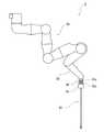
図1は、本発明の一実施形態に係る外科手術システム100の全体的な構成を示す概略図である。図1に示すように、外科手術システム100は、ロボット支援手術やロボット遠隔手術などのように、医師などの術者Oが患者側システム1を用いて患者Pに内視鏡外科手術を施すシステムである。[Overview of surgical operation system]
FIG. 1 is a schematic diagram showing an overall configuration of a
外科手術システム100は、患者側システム1と、この患者側システム1を操る操作装置2とを備えている。操作装置2は患者側システム1から離れて配置され、患者側システム1は操作装置2によって遠隔操作される。術者Oは患者側システム1に行わせる動作を操作装置2に入力し、操作装置2はその動作指令を患者側システム1に送信する。そして、患者側システム1は、操作装置2から送信された動作指令を受け取り、この動作指令に基づいて患者側システム1が具備する内視鏡アセンブリ41やインストゥルメント42(外科用器具)などを動作させる。以下、外科手術システム100の各構成要素について詳細に説明する。 The
[操作装置の構成例]
操作装置2は、外科手術システム100と術者Oのインターフェースを構成し、患者側システム1を操作するための装置である。操作装置2は、手術室内において手術台111の傍らに又は手術台111から離れて、或いは、手術室外に設置されている。操作装置2は、術者Oが動作指令を入力するための操作用マニピュレータアーム51や操作ペダル52などの操作入力部50と、内視鏡アセンブリ41で撮影された画像を表示するモニタ53とを含む。術者Oは、モニタ53で患部を視認しながら、操作入力部50を操作して操作装置2に動作指令を入力する。操作装置2に入力された動作指令は、有線又は無線により患者側システム1の後述するコントローラ6に伝達される。[Configuration example of operation device]
The operating
[患者側システムの構成例]
患者側システム1は、外科手術システム100と患者Pとのインターフェースを構成する。患者側システム1は、手術室内において患者Pが横たわる手術台111の傍らに配置されている。手術室内は滅菌された滅菌野である。[Configuration example of patient system]
The
患者側システム1は、ポジショナ7と、ポジショナ7の先端部に取り付けられたプラットホーム5と、プラットホーム5に着脱可能に取り付けられた複数の患者側マニピュレータアーム(以下、単に「アーム3」という)と、複数のアーム3のうち1本のアーム3Aの先端部に取り付けられた内視鏡アセンブリ41と、複数のアーム3のうち余のアーム3Bの先端部に着脱可能に取り付けられたインストゥルメント42と、ポジショナ7及びプラットホーム5を滅菌野から遮蔽する滅菌ドレープ9と、患者側システム1の動作を司るコントローラ6とを備えている。以下、内視鏡アセンブリ41が取り付けられたアーム3を「カメラアーム3A」ということがあり、インストゥルメント42が取り付けられたアーム3を「インストゥルメントアーム3B」ということがある。本実施形態に係る患者側システム1は、1本のカメラアーム3Aと3本のインストゥルメントアーム3Bとの、併せて4本のアーム3を備えている。 The patient-
上記の患者側システム1において、プラットホーム5は、複数のアーム3の拠点となる「ハブ」としての機能を有している。本実施形態では、ポジショナ7及びプラットホーム5によって、複数のアーム3を移動可能に支持するマニピュレータアーム支持体Sが構成されている。但し、マニピュレータアーム支持体Sは少なくともプラットホーム5を含んでいればよく、例えば、ポジショナ7に代えて直動レールや昇降装置、或いは、天井や壁に取り付けられたブラケットに支持されたプラットホーム5によってマニピュレータアーム支持体Sが構成されてもよい。 In the
上記の患者側システム1では、ポジショナ7から内視鏡アセンブリ41又は各インストゥルメント42まで、要素が一連に繋がっている。この明細書では、上記一連の要素において、ポジショナ7(より詳細には、ポジショナ7の手術室の床との接触部)へ向かう側の端部を「基端部」といい、その反対側の端部を「先端部」ということとする。また、基端部を「近位端部」ということがあり、先端部を「遠位端部」ということがある。 In the patient-
インストゥルメント42は、その基端部に設けられた駆動ユニット45と、その先端部に設けられたエンドエフェクタ44(処置具)と、駆動ユニット45とエンドエフェクタ44の間を繋ぐ細長いシャフト43とで構成されている(いずれも、図7参照)。インストゥルメント42には基準方向Dが規定されており、駆動ユニット45、シャフト43、及びエンドエフェクタ44は基準方向Dと平行に並ぶ。インストゥルメント42のエンドエフェクタ44は、動作する関節を有する器具(例えば、鉗子、ハサミ、グラスパー、ニードルホルダ、マイクロジセクター、ステープルアプライヤー、タッカー、吸引洗浄ツール、スネアワイヤ、及び、クリップアプライヤーなど)や、関節を有しない器具(例えば、切断刃、焼灼プローブ、洗浄器、カテーテル、及び、吸引オリフィスなど)からなる群より選択される。 The
上記構成の患者側システム1では、操作装置2から動作指令を受けたコントローラ6が、先ず、プラットホーム5と手術台111又は患者Pとが所定の位置関係となるように、ポジショナ7を動作させてプラットホーム5の位置決めを行う。次に、コントローラ6が、患者Pの体表に留置されたスリーブ(カニューレスリーブ)110と内視鏡アセンブリ41及び各インストゥルメント42が所定の初期位置関係となるように、各アーム3を動作させて内視鏡アセンブリ41及び各インストゥルメント42の位置決めを行う。なお、ポジショナ7と各アーム3の上記の位置決め動作は同時に行われてもよい。そして、コントローラ6は、原則としてポジショナ7を静止させた状態で、操作装置2からの動作指令に応じて、各アーム3を動作させて内視鏡アセンブリ41及び各インストゥルメント42を適宜変位及び姿勢変化させつつ、各インストゥルメント42を動作させて施術する。 In the
[ポジショナの構成例]
ここで、ポジショナ7の構成について詳細に説明する。図2は、ポジショナ7の全体的な構成を示す側面図である。[Configuration example of positioner]
Here, the configuration of the positioner 7 will be described in detail. FIG. 2 is a side view showing the overall configuration of the positioner 7.
図2に示すように、ポジショナ7は、水平多関節形ロボットを基調としており、手術室の床に載置されたベース70と、昇降軸72と、ベース70と昇降軸72の基端部とを連結する揺動アーム71と、昇降軸72の先端部に連結された水平アーム73とを含む。水平アーム73の先端部には、プラットホーム5が連結されている。 As shown in FIG. 2, the positioner 7 is based on a horizontal articulated robot, and includes a base 70 placed on the floor of an operating room, an elevating
ベース70は、例えば、ブレーキ付台車であって、所望の位置へ移動させて、そこで静止させることができる。このベース70に、揺動アーム71の基端部が回転関節J71を介して連結されている。この回転関節J71の動作により、揺動アーム71は、ベース70に規定された水平な回転軸(揺動軸)を中心として回動(揺動)する。また、揺動アーム71の先端部は、回転関節J72を介して昇降軸72の基端部と連結されている。この回転関節J72の動作により、揺動アーム71は、昇降軸72の基端部に規定された水平な回転軸を中心として回動(揺動)する。 The
昇降軸72は、垂直に延在し、垂直方向に伸縮可能である。本実施形態の昇降軸72は、筒部材72a、この筒部材72aに垂直方向へ進退可能に挿入された中空の軸部材72b、及び、筒部材72aと軸部材72bとを連結する並進関節J73を含む。この並進関節J73の動作により、軸部材72bは筒部材72aに対して垂直方向へ進退移動する。 The elevating
水平アーム73は、水平に延びる第1リンク74及び第2リンク75と、第2リンク75の先端部に連結された手首リンク76とを含む。手首リンク76の先端部には、プラットホーム5が接続されている。 The
第1リンク74の基端部は、回転関節J74を介して昇降軸72の先端部と連結されている。第1リンク74と昇降軸72とは直角を成している。上記回転関節J74の動作により、第1リンク74は昇降軸72の先端部に規定された垂直な回転軸を中心として回動する。第1リンク74の先端部は、回転関節J75を介して第2リンク75の基端部と連結されている。この回転関節J75の動作により、第2リンク75は、第1リンク74の先端部に規定された垂直な回転軸を中心として回動する。 The proximal end of the
第2リンク75の先端部は、回転関節J76を介して手首リンク76の基端部と連結されている。この回転関節J76の動作により、手首リンク76は、第2リンク75の先端部に規定された水平な回転軸を中心として回動する。定常時の手首リンク76は垂直に延びており、この手首リンク76の先端部に接続されたプラットホーム5は水平な姿勢である。 The distal end of the
ここで、ポジショナ7の制御系統の構成について説明する。図3は、ポジショナ7の制御系統の概略構成を示すブロック図である。図3に示すように、ポジショナ7は、各関節J71〜J76に対応して、駆動用のサーボモータM71〜M76、及び、サーボモータM71〜M76の回転角を検出するエンコーダE71〜E76を備えている。なお、この図では、関節J71〜J76のうち、回転関節J71と回転関節J76との駆動系統が代表的に示され、余の関節J73〜J75の駆動系統は省略されている。 Here, the configuration of the control system of the positioner 7 will be described. FIG. 3 is a block diagram showing a schematic configuration of a control system of the positioner 7. As shown in FIG. 3, the positioner 7 includes driving servomotors M71 to M76 and encoders E71 to E76 for detecting the rotation angles of the servomotors M71 to M76, corresponding to the joints J71 to J76. I have. In this figure, among the joints J71 to J76, the drive system of the rotary joint J71 and the rotary joint J76 is representatively shown, and the drive system of the remaining joints J73 to J75 is omitted.
コントローラ6は、ポジショナ7の動作を司るポジショナ制御部601を含む。ポジショナ制御部601にはサーボ制御部C71〜C76が電気的に接続され、サーボ制御部C71〜C76には図示されない増幅回路などを介してサーボモータM71〜M76が電気的に接続されている。 The
上記構成において、操作装置2に入力された動作指令に基づいて、ポジショナ制御部601にプラットホーム5の位置姿勢指令が入力される。ポジショナ制御部601は、位置姿勢指令とエンコーダE71〜E76で検出された回転角とに基づいて、位置指令値を生成して出力する。この位置指令値を取得したサーボ制御部C71〜C76は、エンコーダE71〜E76で検出された回転角及び位置指令値に基づいて駆動指令値(トルク指令値)を生成して出力する。この駆動指令値を取得した増幅回路は、駆動指令値に対応した駆動電流をサーボモータM71〜M76へ供給する。このようにして、プラットホーム5が、位置姿勢指令と対応する位置及び姿勢に到達するように、各サーボモータM71〜M76がサーボ制御される。 In the above configuration, a position and orientation command of the
上記の通り、ポジショナ7は、プラットホーム5の位置姿勢指令に応じて態様を変化させることができる。ここで、図2に示すように、ポジショナ7の基本姿勢を、揺動アーム71及び昇降軸72が垂直に延在し、水平アーム73が水平に延在し、且つ、手首リンク76に接続されたプラットホーム5が水平な状態とする。 As described above, the positioner 7 can change the mode according to the position and orientation command of the
図4に示すように、上記基本姿勢から揺動アーム71を垂直から傾ける場合に、ポジショナ制御部601は、回転関節J71を動作させて揺動アーム71を垂直から傾けるとともに、回転関節J72を動作させて昇降軸72の垂直な姿勢を維持する。このようにして、揺動アーム71の垂直からの傾きにかかわらず、昇降軸72の垂直及び水平アーム73の水平が維持される。 As shown in FIG. 4, when the
上記のように揺動アーム71が垂直から傾くと、ポジショナ7は全体としてC字形状を呈する。これにより、ポジショナ7は、ベース70が手術台111の下方に位置し、昇降軸72が手術台111の側方に位置し、且つ、水平アーム73が手術台111の上方に位置する態様を取ることができる。このように、ベース70が手術台111の下方に収められることにより、手術中に手術台111の周囲で手術を補助する補助者の動線を確保することができる。 When the
更に、図5に示すように、手首リンク76を垂直から傾けるように回転関節J76を駆動すると、プラットホーム5が水平から傾く。プラットホーム5が水平から傾くと、プラットホーム5に取り付けられたアーム3の基本軸線(旋回軸線)Lpが一斉に垂直から傾くこととなる。その結果、インストゥルメント42に規定された基準方向Dの角度範囲が拡張され、インストゥルメント42を垂直からより大きく傾けて患者Pへ挿入することが可能となる。このようにして、患者Pの臥位や手術位置に応じて、患者Pに対するインストゥルメント42の挿入方向を適切に調整することができる。 Further, as shown in FIG. 5, when the rotary joint J76 is driven so that the
以上にポジショナ7の好適な実施形態を説明したが、上記のポジショナ7の構成は例えば以下のように変更することができる。 Although the preferred embodiment of the positioner 7 has been described above, the configuration of the positioner 7 can be changed as follows, for example.
例えば、上記実施形態のポジショナ7において、昇降軸72は垂直方向に伸縮するが、図6に示すように、昇降軸72に代えて伸縮しない柱状部材72’を用いてもよい。この変形例では、並進関節J73は省略される。なお、上記実施形態のポジショナ7では、主に昇降軸72の伸縮によってプラットホーム5の高さ位置を調整するが、上記変形例では、主に揺動アーム71の垂直からの傾きによってプラットホーム5の高さ位置を調整する。 For example, in the positioner 7 of the above-described embodiment, the elevating
[アームの構成例]
ここで、アーム3の構成について詳細に説明する。図7では、患者側システム1が備える複数のアーム3のうちの1本の概略構成が示されている。図7に示すように、アーム3は、アーム本体30と、アーム本体30の先端部に連結された並進アーム35とを備え、基端部に対し先端部を3次元空間内で移動させることができるように構成されている。なお、本実施形態では、患者側システム1が具備する複数のアーム3はいずれも同様又は類似の構成を有するが、複数のアーム3のうち少なくとも1本が余と異なる構成を有してもよい。[Example of arm configuration]
Here, the configuration of the
アーム3がインストゥルメントアーム3Bの場合には、並進アーム35の先端にインストゥルメント42を保持するホルダ(器具保持部)36が設けられる。ホルダ36には、インストゥルメント42が着脱可能に保持されている。ホルダ36に保持されたインストゥルメント42のシャフト43は、基準方向Dと平行に延在する。 When the
また、アーム3がカメラアーム3Aの場合には、上記インストゥルメントアーム3Bと同様に、並進アーム35の先端部にホルダ36が設けられ、このホルダ36に内視鏡アセンブリ41が着脱可能に保持される。ここで、カメラアーム3Aに設けるホルダ36は、インストゥルメントアーム3Bに設けるホルダ36から態様が異なっていてもよい。或いは、手術中に内視鏡アセンブリ41を交換することは稀であるので、カメラアーム3Aに内視鏡アセンブリ41が固定されていてもよい。 When the
アーム3は、プラットホーム5に対し着脱自在(すなわち、取り付けたり取り外したりが容易)であって、洗浄処理及び滅菌処理のための耐水性、耐熱性、及び耐薬品性を備えている。アーム3の滅菌処理には様々な方法があるが、例えば、高圧蒸気滅菌法、EOG滅菌法、消毒薬による化学滅菌法などが選択的に用いられてよい。高圧蒸気滅菌法では、オートクレーブなどの高圧容器にアーム3を封入し、所定圧力の飽和水蒸気に所定時間(例えば、115℃で30分間、121℃で20分間、又は、126℃で15分間)晒す。EOG滅菌法では、容器にアーム3を封入し、この容器に450〜1000mg/Lの酸化エチレンガスを流通させる。化学滅菌法では、例えば、グルタラールなどの消毒薬にアーム3を浸漬する。 The
[アーム本体の構成例]
アーム本体30は、プラットホーム5に着脱可能に取り付けられるベース80と、ベース80から先端部に向けて順次連結された第1リンク81〜第6リンク86とを含む。より詳細には、ベース80の先端部に、捩り関節J31を介して第1リンク81の基端部が連結されている。第1リンク81の先端部に、捩り関節J32を介して第2リンク82の基端部が連結されている。第2リンク82の先端部に、曲げ関節J33を介して第3リンク83の基端部が連結されている。第3リンク83の先端部に、捩り関節J34を介して第4リンク84の基端部が連結されている。第4リンク84の先端部に、曲げ関節J35を介して第5リンク85の基端部が連結されている。第5リンク85の先端部に、捩り関節J36を介して第6リンク86の基端部が連結されている。第6リンク86の先端部に、並進アーム35の基端部が連結されている。[Configuration example of arm body]
The
アーム本体30の外殻は、主にステンレスなどの耐熱性及び耐薬品性を有する部材で形成されている。また、リンク同士の連結部には、耐水性を備えるためのシール(図示せず)が設けられている。このシールは、高圧蒸気滅菌法に対応する耐熱性や、消毒薬に対する耐薬品性を備えている。なお、リンク同士の連結部において、連結される一方のリンクの端部の内側に他方のリンクの端部が挿入されており、これらのリンクの端部同士の間を埋めるようにシールが配置されることによって、シールが外観から隠蔽されている。これにより、シールとリンクとの間から水、薬液、蒸気の浸入が抑制されている。 The outer shell of the
ここで、図8及び図9を用いて、アーム本体30の駆動系統及び制御系統の構成について説明する。図8は、アーム本体30の制御系統の概略構成を示すブロック図であり、図9は、アーム本体30の駆動系統のレイアウトを示すアーム本体30の概略断面図である。 Here, a configuration of a drive system and a control system of the
上記構成のアーム本体30には、各関節J31〜J36に対応して、駆動用のサーボモータM31〜M36、サーボモータM31〜M36の回転角を検出するエンコーダE31〜E36、及び、サーボモータM31〜M36の出力を減速させてトルクを増大させる減速機R31〜R36が設けられる。なお、図8では、関節J31〜J36のうち、捩り関節J31と捩り関節J36との制御系統が代表的に示され、余の関節J33〜J35の制御系統は省略されている。なお、エンコーダE31〜E36は、サーボモータM31〜M3の回転位置(回転角)を検出する回転位置検出手段の一例として設けられており、エンコーダE31〜E36に代えてレゾルバなどの回転位置検出手段が用いられてもよい。また、アーム本体30の駆動系統の上記の各要素及びこれらのための配線並びに制御部は耐高温材料で構成されて、滅菌処理のための耐熱性が備えられている。 In the
ベース80と第1リンク81とを連結する捩り関節J31において、第1リンク81の基端部にサーボモータM31が設けられ、ベース80の先端部に減速機R31が設けられる。本実施形態に係る減速機R31は、入力された動力の回転速度を減じるギア及びその出力を受ける出力ギアを含むユニットタイプのものである。サーボモータM31は、その出力軸が捩り関節J31の回転軸と平行となるように配置されている。エンコーダE31はサーボモータM31に付設されている。サーボモータM31の出力は、減速機R31に入力される。減速機R31の出力ギアは第1リンク81に固定されているので、減速機R31からの出力によって第1リンク81がベース80に対して回転する。 In the torsional joint J31 connecting the
また、第1リンク81と第2リンク82とを連結する捩り関節J32において、第1リンク81の先端部にサーボモータM32が設けられ、第2リンク82の基端部に減速機R32が設けられている。サーボモータM32は、その出力軸が捩り関節J32の回転軸と平行となるように配置されている。エンコーダE32はサーボモータM32に付設されている。 In the torsion joint J32 connecting the
また、第2リンク82と第3リンク83とを連結する曲げ関節J33において、第2リンク82の先端部に減速機R33が設けられ、第3リンク83の基端部にサーボモータM33が設けられている。サーボモータM33は、その出力軸が曲げ関節J33の回転軸と平行となるように配置されている。エンコーダE33はサーボモータM33に付設されている。 In the bending joint J33 connecting the
上記に倣って、余の関節J34〜J36にもサーボモータM34〜M36、エンコーダE34〜E36、及び、減速機R34〜R36が配置されている。 Similar to the above, servo motors M34 to M36, encoders E34 to E36, and reduction gears R34 to R36 are arranged at the remaining joints J34 to J36.
サーボモータM31〜M36は、出力が小さく(例えば、80W程度)、軽量且つ小型のものが採用されている。また、減速機R31〜R36は、軸心方向の寸法の小さい扁平な形状であって、高減速比(例えば、100以上)で高トルクを得られるものが採用されている。患者側システム1のアーム3には、一般的な産業用マニピュレータのような高速動作が求められないことから、出力の大きなサーボモータは必要とされない。そこで、比較的出力の小さいサーボモータM31〜M36と比較的高減速比の減速機R31〜R36とを組み合わせて用いることによって、必要なトルクを確保しつつアーム3の軽量化及び小型化を実現している。 The servo motors M31 to M36 are small in output (for example, about 80 W), lightweight and small. The reduction gears R31 to R36 have a flat shape with a small size in the axial direction and are capable of obtaining a high torque at a high reduction ratio (for example, 100 or more). Since the
加えて、一般的な産業用マニピュレータではサーボモータの出力は出力ギア、減速機、負荷の順に伝達されるところ、本実施形態に係るアーム3ではサーボモータの出力は減速機、出力ギア、負荷の順に伝達される。このように、出力ギアに対し入力側に減速機をレイアウトすることによっても、アーム3の軽量化及び小型化を実現している。 In addition, in a general industrial manipulator, the output of the servomotor is transmitted in the order of an output gear, a speed reducer, and a load. In the
コントローラ6は、アーム本体30の動作を司るアーム本体制御部602を含む。アーム本体制御部602にはサーボ制御部C31〜C36が電気的に接続され、サーボ制御部79には図示されない増幅回路などを介してサーボモータM31〜M36が電気的に接続されている。 The
上記構成において、操作装置2に入力された動作指令に基づいて、アーム本体制御部602にアーム本体30の先端部の位置姿勢指令が入力される。アーム本体制御部602は、位置姿勢指令とエンコーダE31〜E36で検出された回転角とに基づいて、位置指令値を生成して出力する。この位置指令値を取得したサーボ制御部C31〜C36は、エンコーダE31〜E36で検出された回転角及び位置指令値に基づいて駆動指令値(トルク指令値)を生成して出力する。この駆動指令値を取得した増幅回路は、駆動指令値に対応した駆動電流をサーボモータM31〜M36へ供給する。このようにして、アーム本体30の先端部が、位置姿勢指令と対応する位置及び姿勢に到達するように、各サーボモータM31〜M36がサーボ制御される。 In the above configuration, a position and orientation command of the distal end of the
[アームとプラットホームとの連結構造]
ここで、プラットホーム5とアーム3との連結構造について説明する。[Connection structure between arm and platform]
Here, a connection structure between the
アーム3のベース80は、プラットホーム5に対し着脱自在である。換言すれば、患者側システム1から、アーム3を丸ごと取り外したり、取り付けたりすることが容易である。本実施形態では、4本のアーム3がプラットホーム5に対し着脱可能であるが、患者側システム1が具備するアーム3のうち少なくとも1本がプラットホーム5に対し着脱可能であればよい。 The
患者側システム1から取り外されたアーム3は、洗浄処理及び滅菌処理が施されたのち、制限された回数内で再利用される。このようにして、アーム3を手術の度に滅菌された清浄なものに取り換えられる。したがって、アーム3は従来のように滅菌ドレープで覆われず、滅菌野に曝されてもよい。 The
図10は、プラットホーム5とアーム3との連結構造を示す平面図であり、図11は図10におけるXI−XI矢視断面図である。図10及び図11に示すように、アーム3のベース80の基端部は円筒形状を呈し、その周囲又は基端面に少なくとも1つのインターフェース部(以下、「I/F部801」と示すことがある)を有する。本実施形態に係るI/F部801は、ベース80の外周面に形成された突起であるが、I/F部801の態様はこれに限定されない。 FIG. 10 is a plan view showing a connection structure between the
I/F部801には、アーム3に識別情報などを付帯させるためのICタグ91が埋め込まれている。ICタグ91は、ICチップやアンテナを含み、ICチップはマイクロコンピュータやEEPROM、RAMなどを含む(いずれも図示略)。ICタグ91には、アーム3の個体識別情報、型番、使用回数などが記憶される。 An
また、I/F部801には、1以上のコネクタ92が設けられる。1以上のコネクタ92は、アーム3へ電気を供給する電線のコネクタ、アーム3と信号を送受信する通信配線のコネクタなどを含む。 The I /
一方、プラットホーム5には、ベース80のI/F部801が接続される取付ポート55が設けられる。本実施形態に係る取付ポート55(マニピュレータアーム取付部の一例)は、突起状のI/F部801が嵌合可能な凹部であるが、取付ポート55の態様はこれに限定されない。 On the other hand, the
本実施形態では、プラットホーム5に4本のアーム3が着脱可能に取り付けられるので、プラットホーム5には少なくとも4つの取付ポート55が設けられている。プラットホーム5は、平面視において四角形の隣接する2つの角を面取りしたような6角形を呈し、そのうち連続する3つの側面は同一の方向に向かう成分を有する。この3つの側面の各々に1つずつの取付ポート55が設けられている。また、プラットホーム5の下部が一部切り欠かれることによって側方を向いた壁59が形成されており、この壁59にも上記の上段の3つの取付ポート55と同様に、下段の3つの取付ポート55が設けられている。本実施形態では、下段の3つの取付ポート55のうちの1つが使用され、余の2つは空いている。このようにプラットホーム5に複数の取付ポート55が設けられており、手術ごとに使用する取付ポート55を選択することができる。 In this embodiment, since the four
上記のようにアーム3のベース80に設けられたI/F部801と、プラットホーム5に設けられた取付ポート55とにより、アーム3とプラットホーム5とを連結するカップリング機構が構成されている。そして、プラットホーム5の取付ポート55にベース80のI/F部801が嵌め込まれることによって、プラットホーム5にベース80(即ち、アーム3)が取り付けられる。 As described above, the coupling mechanism that connects the
プラットホーム5の取付ポート55には、I/F部801に設けられたコネクタ92と対応する位置にソケット56が設けられる。I/F部801と取付ポート55との連結に伴い、コネクタ92とソケット56とが自動的に接続される。ソケット56には、プラットホーム5及びポジショナ7を構成している中空状の要素(軸やリンクなど)の内部空間を通じて電線及び/又は通信配線が接続されている。なお、コネクタ92はアーム3の表面に露出しておりソケット56と接触可能であるが、コネクタ92がアーム3の表面近傍に埋め込まれて、電磁誘導などによってソケット56とコネクタ92とが非接触で電気的に接続される構成が採用されてもよい。また、I/F部801にソケット56が設けられ、取付ポート55にコネクタ92が設けられてもよい。 The mounting
また、プラットホーム5には、アーム3に埋め込まれたICタグ91の情報の読み出しと書き込み(記憶)を行うリーダーライター93が設けられている。このリーダーライター93は、プラットホーム5の各取付ポート55に対応して設けられており、後述するコントローラ6へ、ICタグ91から読み出した情報を出力する。このリーダーライター93は、プラットホーム5に取り付けられた各アーム3のICタグ91を個別に読み取るものであってもよいし、プラットホーム5に取り付けられた全部のアーム3のICタグ91を一度に読み取るものであってもよい。 In addition, the
更に、プラットホーム5とベース80には、プラットホーム5からベース80が落脱しないように、プラットホーム5に取り付けられたアーム3の取付ロック(保持)及び取付ロック解除(保持解除)が可能な1組以上の取付ロック機構94が設けられている。なお、取付ロックとは、プラットホーム5の取付ポート55に取り付けられたアーム3のI/F部801を当該取付ポート55に固定することをいい、取付ロック解除とは、その固定を解除することをいう。 Furthermore, the
取付ロック機構94は、プラットホーム5の取付ポート55又はその近傍に設けられた支持体側係合部94aと、アーム3のI/F部801又はその近傍に設けられたアーム側係合部94bとの協働により構成されている。支持体側係合部94aとアーム側係合部94bとのうち、一方が他方と係合し、他方が一方に係合される。そして、取付ロック機構94において、支持体側係合部94aとアーム側係合部94bの係合によってI/F部801が取付ポート55に取り付けられた状態でロックされ、支持体側係合部94aとアーム側係合部94bの係合解除によってI/F部801が取付ポート55から離脱できるようにロックが解除される。 The mounting
上記のような取付ロック機構94は、例えば、プラットホーム5とベース80の両者のうち一方に設けられた突起と他方に設けられた掛金付レバー、両者のうち一方に設けられた凹部と他方に設けられた係合爪、両者のうち一方に設けられた凹部と他方に設けられたボールプランジャ、からなる群より選択される。或いは、取付ロック機構94は、他の公知の取付ロック機構であってもよい。但し、取付ロック機構94は、ボルト・ナットなど取付ロック/取付ロック解除に工具を使用するものではなく、ワンタッチ操作で取付ロック/取付ロック解除できるものが望ましい。 The mounting
図12は、プラットホーム5に取り付けたアーム3を管理するための構成を示すブロック図である。図12に示すように、コントローラ6は、プラットホーム5に取り付けたアーム3を管理するためのアーム管理部(管理装置)603を含む。アーム管理部603には、リーダーライター93が電気的に接続されている。 FIG. 12 is a block diagram showing a configuration for managing the
アーム管理部603は、プラットホーム5からアーム3への給電に基づいて、コネクタ92とソケット56とが接続されたことを検出する。プラットホーム5からアーム3への給電は、例えば、ソケット56までの電線又は通信配線に設けた電流検出センサ(検出センサ57)からの検出信号に基づいて検出することができる。コネクタ92とソケット56との接続は、即ち、取付ポート55にI/F部801が正常に取り付けられていることを意味する。つまり、プラットホーム5からアーム3への給電の有無に基づいて、取付ポート55に取り付けられたアーム3の有無を検出することができる。このようにして、アーム管理部603は、プラットホーム5が具備する各取付ポート55についてアーム3が取り付けられたことを検知することができる。 The
但し、取付ポート55に取り付けられたアーム3の有無を検出するために、接触式又は非接触式の物体検出センサ(図示せず)をプラットホーム5に設けてもよい。この場合、アーム管理部603は、この検出センサからの検出信号に基づいて取付ポート55にアーム3が取り付けられたことを検出する。 However, in order to detect the presence or absence of the
アーム管理部603は、取付ポート55にアーム3が取り付けられたことを検出すると、リーダーライター93に読み出し動作をさせ、リーダーライター93がICタグ91から読み取った情報に基づいて、プラットホーム5に接続されている各アーム3の、個体識別情報、型番情報(種類)、使用回数情報などを取得する。アーム管理部603は、取得した各情報を、そのアーム3が取り付けられたプラットホーム5上の取付位置情報(即ち、取付ポート55)に関連づけて一時的に記憶する。なお、複数の取付ポート55は各々識別されている。 When detecting that the
また、操作装置2を介して、コントローラ6には予め手術情報が入力されて設定(記憶)されている。この手術情報には、手術で使用される複数のアーム3の組合せが含まれている。 In addition, surgery information is previously input and set (stored) in the
アーム管理部603は、リーダーライター93から取得した情報に含まれる個体識別情報の組合せが、上記手術情報として設定されたものと対応しているか否かを判断する。アーム管理部603は、組合せが手術情報として設定されたものと対応していなければ、コントローラ6に接続された警告器605を通じて警告を出力する。なお、警告器605は、光、音、及び画像のうち1つ以上によって術者Oに対し警告するものである。このようにして、アーム管理部603は、適切なアーム3が取り付けられるように、プラットホーム5に取り付けられるアーム3を管理している。 The
上記手術情報には、手術で使用されるアーム3の個体識別情報と当該アーム3が取り付けられるべきプラットホーム5の取付位置(即ち、取付ポート55)との組合せに係る情報が含まれていてもよい。 The surgery information may include information on a combination of the individual identification information of the
この場合、アーム管理部603は、リーダーライター93から取得した情報に含まれる個体識別情報と、それに関連付けられて記憶されたプラットホーム5上の取付位置情報(即ち、取付ポート55)との組合せが、上記手術情報として設定されたものと対応しているか否かを判断する。アーム管理部603は、組合せが手術情報として設定されたものと対応していなければ、コントローラ6に接続された警告器605を通じて警告を出力する。このようにして、アーム管理部603は、アーム3がプラットホーム5上の適切な位置に取り付けられるように、且つ、各取付ポート55に適切なアーム3が取り付けられるように、プラットホーム5に取り付けられるアーム3を管理している。 In this case, the
また、手術情報には、手術で使用されるアーム3の型番情報と、そのアーム3が取り付けられるべきプラットホーム5上の取付位置(即ち、取付ポート55)との組合せに係る情報が含まれていてもよい。 The surgery information includes information on the combination of the model number information of the
この場合、アーム管理部603は、リーダーライター93から取得した情報に含まれる型番情報と、それに関連付けられた取付位置(取付ポート55)との組合せが、上記手術情報として設定されたものと対応しているか否かを判断し、組合せが手術情報として設定されたものと対応していなければ、コントローラ6に接続された警告器605を通じて警告を出力するように構成されていてよい。 In this case, the
なお、アーム3は型番により種類(カメラアーム3A、インストゥルメントアーム3B)や構造(リンクの長さ、自由度など)などが異なる。上記ではICタグ91に型番情報が記憶されているが、記憶装置604が個体識別情報に関連付けられて型番情報が記憶された型番記憶部を含み、アーム管理部603が個体識別情報に基づいて型番記憶部から対応する型番情報を読み出し、この型番情報が上記処理においてICタグ91から読み出した型番情報に代えて使用されてもよい。 The type (
コントローラ6の記憶装置604は、個体識別情報に関連付けられた使用制限回数が記憶された使用制限回数記憶部を含んでいる。アーム管理部603は、ICタグ91から取得した個体識別情報に基づいて、これに対応する使用制限回数を記憶装置604から読み出し、使用制限回数と取得した使用回数情報と比較する。アーム管理部603は、使用回数情報が使用制限回数を超えていれば、コントローラ6に接続された警告器605を通じて警告を出力する。このようにして、アーム管理部603は、アーム3がその使用制限回数を超えて使用されることのないようにアームの使用回数を管理する。なお、アーム3は消耗品であり、使用制限回数の使用を終えたアーム3は廃棄される。 The
また、アーム管理部603は、ICタグ91から取得した使用回数情報に1を加えた新たな使用回数情報をICタグ91に書き込むように、リーダーライター93を動作させる。この結果、アーム3のICタグ91は自身の使用回数に係る情報を保持する。よって、アーム3を、他の患者側システム1との間で共用することが可能である。 Further, the
なお、上記では、アーム3の使用回数情報をアーム3自身が保持しているが、アーム3の使用回数情報が、コントローラ6の記憶装置604に記憶されていてもよい。この場合、リーダーライター93に代えて、読み出しの機能のみを有するリーダーが用いられてよい。そして、アーム管理部603は、リーダーがICタグ91から読み出した個体識別情報に基づいて記憶装置604から対応する使用回数情報を読み出して、上記の処理に利用してよい。 In the above description, the use frequency information of the
以上に、プラットホーム5とアーム3の連結構造の好適な実施形態を説明したが、上記のプラットホーム5とアーム3の連結構造は例えば以下のように変更することができる。 The preferred embodiment of the connection structure between the
例えば、上記実施形態ではプラットホーム5には6つの取付ポート55が設けられ、これらの取付ポート55のうち4つにアーム3が連結されている。このように、複数の取付ポート55のうち空きの取付ポート55があってもよい。また、プラットホーム5には、5つ以上の取付ポート55が設けられ、手術の内容に対応した適切な位置の取付ポート55が選択的に使用されてもよい。 For example, in the above embodiment, the
また、例えば、上記実施形態ではアーム3自身に情報を保有させるために、アーム3にICタグ91を設けている。但し、ICタグ91は、アーム3に設けられた情報保持手段の一例であって、ICタグ91に代えて又は加えて他の情報保持手段を用いてもよい。例えば、アーム3にバーコードを設け、プラットホーム5にバーコードリーダーを設けてもよい。また、例えば、アーム3に凹凸などの形状記号を設け、プラットホーム5に形状記号を読み取るリーダーを設けてもよい。 Further, for example, in the above embodiment, the
また、例えば、上記実施形態では、アーム3のベース80のI/F部801にコネクタ92が設けられ、プラットホーム5の取付ポート55にソケット56が設けられるが、コネクタ92及びソケット56が省かれてもよい。この場合、アーム3には、I/F部801以外の場所に電力供給のための電線及び/又は通信のための配線が接続される。 Further, for example, in the above embodiment, the
また、例えば、上記実施形態では、アーム3(特に、アーム本体30)の駆動系統は全て自身に搭載されているが、アーム本体30の駆動系統のうち一部がプラットホーム5に設けられてもよい。例えば、図13に示すように、ベース80と第1リンク81とを連結する捩り関節J31において、この捩り関節J31を駆動するサーボモータM31がプラットホーム5に設けられてもよい。 Further, for example, in the above embodiment, the entire drive system of the arm 3 (in particular, the arm main body 30) is mounted on itself, but a part of the drive system of the arm
図13に示す例では、プラットホーム5にサーボモータM31が内装され、サーボモータM31の出力軸96の周囲には雌カプラ形状の取付ポート55が設けられている。一方、アーム3の第1リンク81の基端部に減速機R31の出力部が固定され、ベース80の基端部が取付ポート55と対応する雄カプラ形状のI/F部801とされ、このベース80内に減速機R31へ動力を入力する入力軸95が設けられている。入力軸95は、アーム3の動力系統へ動力を伝達する入力軸である。そして、サーボモータM31の出力軸96と、減速機R31への入力軸95との間には、オルダム継手などの軸継手97が設けられている。上記構成において、プラットホーム5の取付ポート55にアーム3のI/F部801が挿入されると、プラットホーム5とアーム3とが連結されるとともに、サーボモータM31の出力軸96と減速機R31への入力軸95とが動力伝達可能に連結される。 In the example shown in FIG. 13, a servo motor M31 is mounted on the
[並進アームの構成例]
図7に示すように、並進アーム35は、並進アーム35の先端部に取り付けられたホルダ36を基準方向Dに並進移動させることにより、ホルダ36に取り付けられたインストゥルメント42をシャフト43の延在方向に並進移動させる機構である。[Configuration example of translation arm]
As shown in FIG. 7, the
図14は、アーム本体30の先端部及び並進アーム35の構成例を示す部分破断図である。図7及び図14に示すように、並進アーム35は、基端側リンク61と、先端側リンク62と、基端側リンク61と先端側リンク62を連結する第1連結軸63及び第2連結軸66と、連動機構64とを有する。また、並進アーム35の先端部、すなわち先端側リンク62の先端部には、回動軸68が設けられている。 FIG. 14 is a partially cutaway view showing a configuration example of the distal end portion of the arm
図14に示すように、並進アーム35の駆動源は、アーム本体30の先端のリンクすなわち第6リンク86に設けられている。具体的には、第6リンク86の先端部に、第1並進アーム駆動軸37と、第2並進アーム駆動軸38と、第1並進アーム駆動軸37を回動させる並進アーム駆動部47と、第2並進アーム駆動軸38を回動させる並進アーム回転駆動部48とが設けられている。 As shown in FIG. 14, the drive source of the
第1並進アーム駆動軸37及び第2並進アーム駆動軸38は、基端部がアーム本体30の先端部に基準方向Dと直交する第1軸線L1周りに回動可能に取り付けられている。そして、第2並進アーム駆動軸38は、基端部がアーム本体30の内外環境を遮断するシールを備えるシールベアリング30bを介してアーム本体30に保持されている。そして、第2並進アーム駆動軸38は、中空の筒状に形成され、第1並進アーム駆動軸37は、第2並進アーム駆動軸38の内部に入れ子状に配置されている。したがって、第1並進アーム駆動軸37及び第2並進アーム駆動軸38は、同一の軸線周りに回動するように構成されている。本実施の形態において、第1軸線L1は、アーム本体30の旋回軸線Lp(図7参照)を中心とする円の接線方向に延在するように構成されている。すなわち、第1軸線L1は、図7において、奥行き方向に延在している。そして、第1並進アーム駆動軸37及び第2並進アーム駆動軸38は、アーム本体30の先端部から突出し、並進アーム35の基端側リンク61に連結されている。すなわち、アーム本体30及び並進アーム35は、第1並進アーム駆動軸37及び第2並進アーム駆動軸38を介して連結されている。第1並進アーム駆動軸37は、第2並進アーム駆動軸38との差動により並進アーム35を動作させる駆動軸であり、第2並進アーム駆動軸38は、第1並進アーム駆動軸37との差動により並進アーム35を第1軸線L1周りに回動させる駆動軸である。 The first translation
そして、第1並進アーム駆動軸37及び第2並進アーム駆動軸38は、別個の駆動部によってそれぞれ独立して回動するように構成されている。すなわち、第1並進アーム駆動軸37は、並進アーム駆動部47の出力軸47aに連結され、並進アーム駆動部47の出力軸47aの回転により回転する。また、第2並進アーム駆動軸38は、並進アーム回転駆動部48の出力軸48aに連結され、並進アーム回転駆動部48の出力軸48aの回転により回転する。これらの駆動部は例えばサーボモータである。したがって、第1並進アーム駆動軸37及び第2並進アーム駆動軸38の第1軸線L1周りの角度位置を互いに独立して制御可能に構成されている。 The first translation
基端側リンク61は、第1軸線L1周りに回動可能に基端部がアーム本体30の先端部30aに連なっている。なお、「連なる」とは、2つのものが直接接続されている場合のみならず、2つのものの間に他のものが介在し、間接的に接続されている場合も含む場合も意味するものとする。そして、基端側リンク61は、退避角度位置P1(図15参照)と、退避角度位置P1よりも基準方向Dにおいて第1軸線L1から離れる側に基端側リンク61の先端部が位置する進出角度位置P2(図15参照)とを含む範囲で回動するよう構成されている。基端側リンク61は、中空である。そして、基端側リンク61の基端部に第1並進アーム駆動軸37及び第2並進アーム駆動軸38の先端部が挿通され、外側に位置する第2並進アーム駆動軸38は、内外空間を遮断するシールを備えるシールベアリング61aを介して基端側リンク61に保持されている。そして、基端側リンク61に第1並進アーム駆動軸37の先端部が固定されている。したがって、並進アーム駆動部47の出力軸47aの回転により第1並進アーム駆動軸37が回転し、更に第1並進アーム駆動軸37の回転によって、基端側リンク61が第1軸線L1周りに回動するように構成されている。このように、基端側リンク61は、アーム本体30の先端部30aに取り付けられている。 The
先端側リンク62は、軸線L1と平行に延在する第2軸線L2周りに回動可能に基端部が基端側リンク61の先端部に連なっている。そして、先端側リンク62は、縮閉角度位置P3(図15参照)と、縮閉角度位置P3よりも基端側リンク61と成す角の角度が大きい拡開角度位置P4とを含む範囲で回動するよう構成されている。このように、基端側リンク61及び先端側リンク62は、L字状に屈折した姿勢をとるように構成されている。先端側リンク62は、中空である。第1連結軸63は、基端部が基端側リンク61の先端部に固定され、先端部が第2軸線L2周りに回動可能に先端側リンク62の基端部に取り付けられている。そして、第2連結軸66は、基端部が基端側リンク61の内外空間を遮断するシールを備えるシールベアリング61bを介して基端側リンク61に第2軸線L2周りに回動可能に取り付けられ、先端部が先端側リンク62の基端部に固定されている。そして、第2連結軸66は、中空の筒状に形成され、第1連結軸63は、第2連結軸66の内部に入れ子状に配置されている。したがって、第1連結軸63及び第2連結軸66は、同一の軸線周りに回動するように構成されている。そして、並進アーム35は、基端側リンク61の基端部と先端側リンク62の先端部とを結ぶ仮想の直線L(図15参照)が基準方向Dに向くように構成されている。このように、先端側リンク62の基端部は、基端側リンク61の先端部に取り付けられている。 The proximal end of the
回動軸68は、基端部が、第1軸線L1及び第2軸線L2と平行に延在する第3軸線L3周りに回動可能に先端側リンク62の先端部に取り付けられ、先端部がホルダ36に固定されている。回動軸68は、先端側リンク62の内外空間を遮断するシールを備えるシールベアリング62aを介して先端側リンク62の先端部に保持されている。本実施の形態において、並進アーム35は、アーム本体30の先端部30aから基準方向Dにおいてホルダ36に保持されたインストゥルメント42のシャフト43の基端部から先端部に向かう側に位置するように配設されている。回動軸68の軸線(第3軸線L3)と第1連結軸63及び第2連結軸66の軸線(第2軸線L2)との距離は、第1並進アーム駆動軸37及び第2並進アーム駆動軸38の軸線(第2軸線L2)と第1連結軸63及び第2連結軸66の軸線(第1軸線L1)との距離と同一に構成される。 The
連動機構64は、基端側リンク61の退避角度位置P1(図15参照)から進出角度位置P2(図15参照)に向かう回動動作に連動して先端側リンク62を縮閉角度位置P3(図15参照)から拡開角度位置P4(図15参照)に向かって回動させ、且つ基端側リンク61の進出角度位置P2(図15参照)から退避角度位置P1(図15参照)に向かう回動動作に連動して先端側リンク62を拡開角度位置P4(図15参照)から縮閉角度位置P3(図15参照)に向かって回動させる機構である。すなわち、先端側リンク62は、並進アーム駆動部47の駆動力が連動機構64によって伝達されることにより回動するよう構成されている。また、連動機構64は、先端側リンク62の先端部を基準方向Dに直進動作させるよう構成されている。以下に、連動機構64の一例としてタイミングベルトを用いた機構を例示する。 The interlocking
本実施の形態において、連動機構64は、2対のプーリ(第1プーリ65a・第2プーリ65b、第3プーリ65c・第4プーリ65d)と、各対のプーリに掛け渡された2本の環状のタイミングベルト(第1ベルト67a,第2ベルト67b)とを含む。 In this embodiment, the interlocking
第1プーリ65aは、第2並進アーム駆動軸38の先端部に固定され、基端側リンク61の内部空間のうち基端側の部分に位置している。したがって、第1プーリ65aは、第1軸線L1周りに回動可能に構成されている。 The
第2プーリ65bは、第1プーリ65aと対をなし、第2連結軸66の基端部に固定され、基端側リンク61の内部空間のうち先端側の部分に位置している。したがって、第2プーリ65bは、第2軸線L2周りに回動可能に構成されている。そして、第1プーリ65a及び第2プーリ65bに、第1ベルト67aが架け渡されている。したがって、第2プーリ65bは、第1プーリ65aの周りを公転することによって回動(自転)するように構成されている。第1プーリ65aの直径と第2プーリ65bの直径との比率であるプーリ比は2:1である。 The
第3プーリ65cは、第1連結軸63の先端部に固定され、先端側リンク62の内部空間のうち基端側の部分に位置している。したがって、第3プーリ65cは、第2軸線L2周りに回動可能に構成されている。 The
第4プーリ65dは、第3プーリ65cと対をなし、回動軸68の基端部に固定され、先端側リンク62の内部空間のうち先端側の部分に位置している。したがって、第4プーリ65dは、第3軸線L3周りに回動可能に構成されている。そして、第3プーリ65c及び第4プーリ65dに、第2ベルト67bが架け渡されている。したがって、第4プーリ65dは、第3プーリ65cの周りを公転することによって回動(自転)するように構成されている。第3プーリ65cの直径と第4プーリ65dの直径との比率であるプーリ比は1:2である。並進アーム35の駆動は、操作装置2に入力された動作指令に基づき、コントローラ6が第1並進アーム駆動軸37及び第2並進アーム駆動軸38を制御することにより行われる。 The
図15は、並進アーム35の動作例を示す図である。 FIG. 15 is a diagram illustrating an operation example of the
以下に、図15を参照しながら並進アーム35の動作例を説明する。 An operation example of the
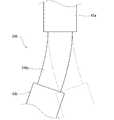
第1並進アーム駆動軸37を第2並進アーム駆動軸38に対して差動させ、第2並進アーム駆動軸38に対してR1方向にα度回転させると、基端側リンク61は、退避角度位置P1から進出角度位置P2に向かってα度回動する。これによって、第2プーリ65bは、第1軸線L1周りに公転する。そして、第1プーリ65a及び第2プーリ65bは、第1ベルト67aによって連結されているので、第2プーリ65bは、第1プーリ65aに対して基端側リンク61の回転方向と反対方向に自転し、第1プーリ65aと第2プーリ65bとの位相が変化する。そして、その角度変位は、そのプーリ比に基づき−2α度となる。そして、第2プーリ65bが回転すると、第2プーリ65bが固定されている第2連結軸66が回転し、第2連結軸66に固定されている先端側リンク62が縮閉角度位置P3から拡開角度位置P4に向かって−2α度回転する。これによって、先端側リンク62の先端部は、基端側リンク61の基端部と先端側リンク62の先端部とを結ぶ仮想の直線L上を移動する。そして、上述の通り、この仮想の直線は基準方向Dに向くように構成されているので、先端側リンク62の先端部は、基準方向Dにおいて、第1軸線L1から離れる側に移動する。また、上記プーリ比の構成から、先端側リンク62の先端部は、基準方向Dに直進動作する。これによって、スリーブ110に挿入したインストゥルメント42を円滑に基準方向Dに動かすことができる。 When the first translation
なお、第1並進アーム駆動軸37と第2並進アーム駆動軸38とを同期させて回動することによって、アーム本体30に対して並進アーム35全体を第1軸線L1周りに旋回させることができる。これによって、基準方向Dの向きを変更することができ、先端側リンク62の先端部が直進動作する方向を第1軸線L1周りに変更することができる。また、第2並進アーム駆動軸38及び並進アーム回転駆動部48を設けずに、第1プーリ65aをアーム本体30の先端部30aに固定し、アーム本体30の先端部を移動させることにより並進アーム35全体を第1軸線L1周りに旋回させてもよい。 By rotating the first translation
そして、先端側リンク62の回転によって、第4プーリ65dは、第2軸線L2周りに公転する。第1連結軸63によって基端側リンク61の先端部に固定されている第3プーリ65cの角度位置は先端側リンク62の回動によって変化せず、更に第3プーリ65c及び第4プーリ65dは、第2ベルト67bによって連結されているので、第4プーリ65dは、第3プーリ65cに対して先端側リンク62の回転方向と反対方向に自転し、第3プーリ65cと第4プーリ65dとの位相が変化する。そして、その角度変位は、そのプーリ比に基づきα度となる。そして、第4プーリ65dが回転すると、第4プーリ65dに固定されている回動軸68が回転し、回動軸68に固定されているホルダ36が第3軸線L3周りにα度回転する。これによって、ホルダ36は、アーム本体30に対する姿勢を維持しながら、基準方向Dにおいて第1軸線L1から離れる側に移動する。 Then, by the rotation of the distal
同様に、第1並進アーム駆動軸37を第2並進アーム駆動軸38に対して差動させ、R2(R1と反対方向)方向に回転させると、基端側リンク61が進出角度位置P2から退避角度位置P1に向かって回動し、先端側リンク62が拡開角度位置P4から縮閉角度位置P3に向かって回動する。これによって、ホルダ36は、アーム本体30に対する姿勢を維持しながら、基準方向Dにおいて、第1軸線L1に近づく側に移動する。 Similarly, when the first translation
このように、並進アーム35は、基端側リンク61が退避角度位置P1に位置すると共に、先端側リンク62が縮閉角度位置P3に位置する折畳状態と、基端側リンク61が進出角度位置P2に位置すると共に、先端側リンク62が拡開角度位置P4に位置する伸長状態との間で遷移することによって、インストゥルメント42を基準方向Dに移動(進退動、往復動)させることができる。したがって、直動関節によってホルダ36を基準方向Dに移動させる構成と比較して、基準方向Dにおけるアーム3の寸法をコンパクトに構成することができる。 As described above, the
また、並進アーム35は、アーム本体30及びホルダ36と回動関節によって接続され、また、並進アーム35を構成するリンク、すなわち基端側リンク61及び先端側リンク62も回転関節によって接続されている。したがって、アームの内部空間の外部空間への露出部分を少なくすることができるので、アームの内部空間で発生した塵、雑菌等が外部空間へ飛散することを効果的に抑制することができる。また、上述の通り、回転関節にシールベアリングを用いることにより、アームの内部空間で発生した塵、雑菌等が外部空間へ飛散することを防止することができる。よって、手術室の汚染を効果的に防止することができる。 The
更に、連動機構64が基端側リンク61の回動動作に連動して先端側リンク62を回動させるように構成されているので、先端側リンク62のみを回動させる駆動部を省くことができ、並進アーム35の構成を簡素化することができる。 Furthermore, since the interlocking
なお、連動機構64の一例としてタイミングベルトを用いた機構を例示したが、この機構に限定されるものではなく、これに代えて、例えば、ギアトレインを含む機構を用いてもよく、公知のリンク機構を用いてもよい。また、基端側リンク61及び先端側リンク62が別個に設けられた駆動部の駆動力によってそれぞれ回動するように構成されていてもよい。 Although a mechanism using a timing belt has been illustrated as an example of the interlocking
[並進アームの変形例1]
図18は、並進アームの変形例1を示す図である。上記実施の形態において、並進アーム35は、アーム本体30の先端部30aから基準方向Dにおいてホルダ36に保持されたインストゥルメント42のシャフト43の基端部から先端部に向かう側に位置するように配設されているがこれに限られるものではない。これに代えて、並進アーム335は、並進アーム35は、アーム本体30の先端部30aから基準方向Dにおいてホルダ36に保持されたインストゥルメント42のシャフト43の先端部から基端部に向かう側に位置するように配設されていてもよい。[
FIG. 18 is a diagram illustrating a first modification of the translation arm. In the above-described embodiment, the
[並進アームの変形例2]
図19は、並進アームの変形例2を示す図である。上記実施の形態において、並進アーム35は、基端側リンク61の先端部に先端側リンク62の基端部が取り付けられている構成を例示したがこれに限られるものではない。これに代えて、以下の通り構成されていてもよい。[
FIG. 19 is a diagram illustrating a second modification of the translation arm. In the above-described embodiment, the
すなわち、並進アーム435は、基端側リンク61と先端側リンク62との間に第1中間リンク461及び第2中間リンク462を有する中間リンクユニット460が介在するように構成されている。また、並進アーム435は、基端側リンク61と第1中間リンク461を連結する第1連結軸463aと、第1中間リンク461と第2中間リンク462とを連結する第2連結軸463bと、第2中間リンク462と先端側リンク62を連結する第3連結軸463cとを有する。 That is, the
そして、図示しない並進アーム435の連動機構は、基端側リンク61の退避角度位置P1から進出角度位置P2に向かう回動動作に連動して、基端側リンク61と第1中間リンク461とが成す関節の角度が大きくなるように第1中間リンク461を第1連結軸463aの軸線周りに回動させ、且つ第1中間リンク461と第2中間リンク462とが成す関節の角度が大きくなるように第2中間リンク462を第2連結軸463bの軸線周りに回動させ、且つ第2中間リンク462と先端側リンク62とが成す関節の角度が大きくなるように先端側リンク62を第3連結軸463cの軸線周りに回動させるように構成されている。 The linkage mechanism of the translation arm 435 (not shown) moves the
これによって、インストゥルメント42の移動距離を大きくすることができる。また、並進アーム35の幅寸法W、すなわち基準方向D及び第1軸線L1と直交する方向における並進アーム35の寸法を小さくすることができる。 As a result, the movement distance of the
[揺動機構の構成例]
図7に示すように、アーム3は、揺動機構46を備えている。揺動機構46は、アーム3とエンドエフェクタ44との間に介在し、基準方向Dを中心とする径方向にシャフト43の先端部、及びエンドエフェクタ44を揺動させる機構である。[Configuration example of swing mechanism]
As shown in FIG. 7, the
揺動機構46は、例えばシャフト43の中間部に設けられている。すなわち、シャフト43は、基端側部材43aと、先端側部材43bとに分割されており、その間に揺動機構46が介在するように設けられている。以下に、揺動機構46の一例として回転2自由度を有する自在継手を用いた機構を例示する。 The
図16は、揺動機構46の構成例を示す図である。 FIG. 16 is a diagram illustrating a configuration example of the
揺動機構46は、第1部材46a、第2部材46b、及び第3部材46cを有する。第1部材46aは、基端側部材43aに固定されている。第2部材46bは、第1部材46aと基準方向Dと直交する第1方向D1に延在する第1回動軸46dによって連結され、第1回動軸46dの軸線周りに回動可能に第1部材46aに取り付けられている。第3部材46cは、第2部材46bと第1方向D1と直交する第2方向D2に延在する第2回動軸46eによって連結され、第2回動軸46eの軸線周りに回動可能に第2部材46bに取り付けられている。 The
図17は、揺動機構46の動作例を示す図である。 FIG. 17 is a diagram illustrating an operation example of the
以下に、図17を参照しながら、揺動機構46の動作例を説明する。 Hereinafter, an operation example of the
インストゥルメント42のエンドエフェクタ44が患者Pの体表の切開部に留置したスリーブ110を介して患者Pの体内に導入され、図17において破線で示す初期状態においては、基準方向Dにスリーブ110が位置している。 The
次に、アーム3がホルダ36を基準方向Dと交差する方向に移動させると、シャフト43の先端側部材43bはスリーブ110を中心に揺動し、シャフト43の先端部及びエンドエフェクタ44は、ホルダ36の移動方向と反対方向に移動する。また、シャフト43の先端側部材43bが揺動すると、シャフト43が挿通されているスリーブ110は、先端側部材43bの延在方向に向くように先端側部材43bと共に揺動する。 Next, when the
このとき、基端側部材43aの軸線上からスリーブ110が外れると、シャフト43の先端側部材43bの延在方向とスリーブ110の挿通孔の向きが一致するようにシャフト43の先端側部材43bが基端側部材43aの軸線を中心とする径方向、すなわち基準方向Dを中心とする径方向に揺動する。これによって、患者Pの留置したスリーブ110がホルダ36の移動方向に牽引されることを防止することができ、患者Pの切開部に与えるダメージを緩和することができる。 At this time, when the
[揺動機構の変形例1]
図20は、揺動機構の変形例1を示す図である。揺動機構は、ボール継手を用いた機構であってもよい。[
FIG. 20 is a diagram illustrating a first modification of the swing mechanism. The swing mechanism may be a mechanism using a ball joint.
すなわち、揺動機構246は、球面状の自由端を有し、シャフト43の先端側部材43bの基端部に取り付けられたボール部246aと、腕状に形成され、シャフト43の基端側部材43aの先端部に取り付けられたソケット246bとを有する。ソケット246bの内周面は略半球面を形成している。このソケット246bの内周面の形状は、ボール部246aの外周面の形状と略同一に形成されている。これにより、ボール部246aの外周面とソケット246bの内周面とが球面対偶を成し、シャフト43の基端側部材43aと先端側部材43bとが少なくとも回転2自由度をもって揺動可能に連結されている。 That is, the
[揺動機構の変形例2]
図21は、揺動機構の変形例2を示す図である。揺動機構は、弾性を有する部材を用いた機構であってもよい。[
FIG. 21 is a diagram illustrating a second modification of the swing mechanism. The swing mechanism may be a mechanism using a member having elasticity.
すなわち、揺動機構346は、基端側部材43aと先端側部材43bとを接続する弾性部346aを有する。弾性部346aが弾性変形することにより、シャフト43の基端側部材43aと先端側部材43bとが少なくとも回転2自由度を持って揺動可能に連結されている。 That is, the
[揺動機構を備えるアームの変形例1]
図22は、揺動機構を備えるアームの変形例を示す図である。上記実施の形態において、揺動機構46がシャフト43の中間部に設けられている構成例を例示したがこれに限られるものではない。これに代えて、揺動機構46は、並進アーム35の先端部とインストゥルメント42との間に介在するように設けられていてもよい。[
FIG. 22 is a diagram illustrating a modification of the arm including the swing mechanism. In the above-described embodiment, the configuration example in which the
すなわち、揺動機構46の第1部材46aが先端側リンク62の先端部に直接取り付けられ、第3部材46cがインストゥルメント42に直接取り付けられている。 That is, the
[揺動機構を備えるアームの変形例2]
図23は、揺動機構を備えるアームの変形例を示す図である。上記実施の形態1において、揺動機構46は、並進アーム35を有するアーム3を備える外科手術システム100に適用したがこれに限られるものではない。これに代えて、揺動機構46は、直動関節235を有するアームに適用してもよい。[
FIG. 23 is a diagram illustrating a modified example of the arm including the swing mechanism. In the first embodiment, the
[総括]
以上に説明したように、本実施形態の外科手術システム100(特に、そのうち患者側システム1)は、外科手術を行うための複数のインストゥルメント42と、プラットホーム5と、プラットホーム5に基端部が着脱可能に取り付けられる複数のアーム3であって、各アーム3の先端部に複数のインストゥルメント42のうちの一つが着脱可能に取り付けられて当該インストゥルメント42を移動可能に支持する複数のアーム3と、プラットホーム5に取り付けられた各アーム3の取付ロック及び取付ロック解除が可能な取付ロック機構94とを備えている。なお、インストゥルメント42に代えて内視鏡アセンブリ41が装着されたアーム3も外科手術システム100に含まれている。[Summary]
As described above, the surgical operation system 100 (particularly, the patient-side system 1) of the present embodiment includes a plurality of
また、本実施形態の外科手術システム100に含まれるアーム3は、支持体(即ち、プラットホーム5、又は、プラットホーム5及びポジショナ7から成る組立体)に取り付けられ、外科手術を行うためのインストゥルメント42が先端部に取り付けられるアーム3であって、ベース80と、ベース80に直列的に連結された少なくとも1つのリンク81〜86と、ベース80の基端部に設けられ、支持体に設けられた支持体側係合部94aと係合可能なアーム側係合部94bを有するI/F部801とを備えている。そして、支持体側係合部94aとアーム側係合部94bの係合によってI/F部801が支持体に取り付けられた状態でロックされ、支持体側係合部94aとアーム側係合部94bの係合解除によってI/F部801が支持体から離脱できるようにロックが解除される。 The
また、本実施形態の外科手術システム100に含まれるマニピュレータアーム支持体Sは、外科手術を行うためのインストゥルメント42を移動可能に支持するアーム3が取り付けられるプラットホーム5と、プラットホーム5を移動可能に支持するポジショナ7とを備えている。プラットホーム5は、アーム3が着脱可能に取り付けられる複数の取付ポート55(アーム取付部)と、アーム3に設けられたアーム側係合部94bと係合可能な支持体側係合部94aとを有する。そして、支持体側係合部94aとアーム側係合部94bの係合によってアーム3が取付ポート55に取り付けられた状態でロックされ、支持体側係合部94aとアーム側係合部94bの係合解除によってアーム3が取付ポート55から離脱できるようにロックが解除される。 In addition, the manipulator arm support S included in the
上記外科手術システム100、アーム3、及びマニピュレータアーム支持体Sによれば、プラットホーム5にアーム3をセットして取付ロック機構94(支持体側係合部94a、アーム側係合部94b)で取付ロックすることにより、プラットホーム5にアーム3を取り付けることができる。また、プラットホーム5に取り付けられたアーム3の取付ロックを解除することにより、プラットホーム5からアーム3を取り外すことができる。このように、プラットホーム5に対しアーム3が着脱自在であり、手術前及び/又は手術中に、プラットホーム5に取り付けられているアーム3を交換したり、プラットホーム5の或る取付ポート55に取り付けられているアーム3を他の取付ポート55に付け替えたりすることができる。このように、手術前及び/又は手術中に、手術の内容に応じた数、種類、組合せのアーム3をプラットホーム5に取り付けることによって、外科手術システム100をその手術に適切にカスタマイズすることができる。 According to the
なお、特許文献1,2に記載されるような従来のシステムでは、外科手術システムが備えるマニピュレータ(マニピュレータアーム、ロボットアーム)の構成はシステムが設置された時点で決定されている。そして、手術前及び/又は手術中にインストゥルメントの変更は可能であるが、それを支持するマニピュレータまで変更することは想定されていなかった。 In the conventional systems as described in
また、本実施形態の外科手術システム100において、プラットホーム5は、複数のアーム3の数以上の数の取付ポート55(マニピュレータアーム取付部)を有している。 Further, in the
これにより、アーム3の取付位置を複数の取付ポート55から選択することができ、外科手術システム100をその手術に適切にカスタマイズすることができる。 Thereby, the mounting position of the
また、本実施形態の外科手術システム100は、プラットホーム5を移動可能に支持するポジショナ7を備えている。 Further, the
これにより、複数のアーム3を包括的に所望の位置へ移動させることができる。 Thereby, the plurality of
また、本実施形態の外科手術システム100は、プラットホーム5に取り付けられたアーム3の有無を検出する検出センサ57と、検出センサ57からの検出信号に基づいて、プラットホーム5にアーム3が取り付けられたことを検知するコントローラ6(特に、アーム管理部603)(管理装置)とを備えている。 In addition, in the
これにより、プラットホーム5にアーム3が取り付けられていること、また、その取付が正常であることを、外科手術システム100がセルフチェックすることができる。 Thereby, the
また、本実施形態の外科手術システム100では、プラットホーム5にアーム3が保有する情報を読み出すリーダーライター93(リーダー)が設けられている。そして、アーム管理部603は、プラットホーム5にアーム3が取り付けられたことを検知すると、リーダーライター93に情報の読み出し動作をさせ、リーダーライター93が読み出した情報を取得し、取得した情報をプラットホーム5上の取付位置情報に関連付けて一時的に記憶する。 Further, in the
このように、アーム3は、自己の情報を自身で保有している。よって、アーム3を他の患者側システム1のプラットホーム5に取り付けて使用することが可能であり、1つのアーム3を複数の患者側システム1の間で共用することができる。 As described above, the
また、本実施形態の外科手術システム100では、アーム3が保有する情報に、当該アームの個体識別情報が含まれており、アーム管理部603には、手術で使用される複数のアーム3の個体識別情報の組合せを含む手術情報が予め設定されている。そして、アーム管理部603は、リーダーライター93から取得した情報に含まれる個体識別情報の組合せが手術情報と対応しなければ警告を出力する。なお、アーム管理部603(コントローラ6)への手術情報の設定・入力は、術者Oが操作装置2を通じて行ってよい。 Also, in the
これにより、不適切な複数のアーム3の組合せで、手術が行われることを回避できる。 Thereby, it is possible to avoid performing an operation using an inappropriate combination of the plurality of
なお、上記外科手術システム100において、アーム3が保有する情報に、当該アーム3の個体識別情報が含まれており、アーム管理部603に、手術で使用されるアーム3の個体識別情報と当該アーム3が取り付けられるべきプラットホーム5上の取付位置との組合せを含む手術情報が予め設定されていてもよい。この場合、アーム管理部603は、リーダーライター93から取得した情報に含まれる個体識別情報とプラットホーム5上の取付位置との組合せが手術情報と対応しなければ警告を出力する。 In the
これにより、適切なアーム3が適切な取付ポート55(即ち、予め設定された取付ポート55)に取り付けられていなければ警告が発される。よって、アーム3が不適切な取付ポート55に取り付けられた状態、及び/又は、不適切なアーム3が取付ポート55に取り付けられた状態で、手術が行われることを回避できる。 Thus, a warning is issued if the
また、上記外科手術システム100において、アーム3が保有する情報に、アーム3の型番情報が含まれており、アーム管理部603に、手術で使用されるアーム3の型番情報と当該アーム3が取り付けられるべきプラットホーム5上の取付位置との組合せを含む手術情報が予め設定されていてもよい。この場合、アーム管理部603は、リーダーライター93から取得した情報に含まれる型番情報とプラットホーム5上の取付位置との組合せが手術情報と対応しなければ警告を出力する。 Further, in the
或いは、上記外科手術システム100において、アーム3が保有する情報に、アーム3の個体識別情報が含まれており、アーム管理部603に、手術で使用されるアーム3の型番情報と当該アーム3が取り付けられるべきプラットホーム5上の取付位置との組合せを含む手術情報が予め設定されていてもよい。この場合、アーム管理部603は、個体識別情報に関連付けられたアーム3の型番情報を記憶した型番記憶部を有し、リーダーライター93から取得した情報に含まれる個体識別情報に基づいて型番記憶部から対応する型番情報を読み出し、読み出した型番情報とプラットホーム5上の取付位置の組合せが手術情報と対応しなければ警告を出力する。 Alternatively, in the
上記いずれの構成においても、適切な型番のアーム3が適切な取付ポート55(即ち、予め設定された取付ポート55)に取り付けられていなければ警告が発されることとなる。よって、アーム3が不適切な取付ポート55に取り付けられた状態、及び/又は、不適切な型番のアーム3が取付ポート55に取り付けられた状態で、手術が行われることを回避できる。 In any of the above configurations, a warning is issued if the
また、本実施形態の外科手術システム100では、アーム3の保有する情報に当該アーム3の個体識別情報及び使用回数情報が含まれている。そして、アーム管理部603は、個体識別情報に関連づけられた使用制限回数を記憶した使用制限回数記憶部を有し、リーダーライター93から取得した情報に含まれる個体識別情報に基づいて使用制限回数記憶部からアーム3の使用制限回数を読み出し、リーダーライター93から取得した情報に含まれる使用回数情報が使用制限回数を超えていれば警告を出力する。 In the
これにより、アーム3が使用制限回数を超えて使用されようとすると警告が発されるので、アーム3が使用制限回数を超えて使用されることを防止することができる。なお、使用制限回数を超えたアーム3は廃棄されてよい。 Accordingly, a warning is issued if the use of the
更に、本実施形態の外科手術システム100では、アーム3が保有する情報は当該アーム3に設けられたICタグ91に記憶されており、リーダーライター93はICタグ91への書き込み機能を有する。そして、アーム管理部603は、リーダーライター93から取得した使用回数情報に1を加えた新たな使用回数情報をICタグ91へ書き込むようにリーダーライター93を動作させる。 Further, in the
これにより、アーム3の使用回数情報は、使用の度に更新されるので、アーム3が使用制限回数を超えて使用されることを防止することができる。また、アーム3の使用回数情報をアーム3自身が保有するので、アーム3を他の患者側システム1との間で共用することができる。 Thus, the information on the number of times of use of the
また、本実施形態の外科手術システム100において、アーム3のI/F部801に、プラットホーム5(支持体)を通された配線とアーム3を通された配線とを接続するコネクタ92が設けられている。より詳細には、プラットホーム5に当該プラットホーム5内に挿通された電線又は通信配線のソケット56が設けられており、アーム3の基端部において当該アーム3がプラットホーム5に取り付けられたときにソケット56と接続される位置に、当該アーム3の電線又は通信配線と接続されたコネクタ92が設けられている。 Further, in the
これにより、プラットホーム5にアーム3を取り付ける動作で、コネクタ92とソケット56とが接続され、プラットホーム5とアーム3に跨った配線系統が接続される。 Thus, by the operation of attaching the
更に、上記実施形態に係る外科手術システム100において、アーム3のI/F部801に、プラットホーム5に設けられた動力源(例えば、サーボモータM31)から入力を受け付ける入力部が設けられていてよい。より詳細には、外科手術システム100において、プラットホーム5にサーボモータM31が設けられており、アーム3の基端部に当該アーム3の動力系統への入力軸95が設けられており、プラットホーム5にアーム3を取り付けたときにサーボモータM31の出力軸96と入力軸95とを動力伝達可能に接続する軸継手97が出力軸96の端部と入力軸95の端部とに設けられていてよい。 Further, in the
これにより、プラットホーム5にアーム3を取り付ける動作で、アーム3の動力系統への入力軸95とサーボモータM31の出力軸96とが接続され、プラットホーム5とアーム3に跨った動力伝達系統が接続される。 Thus, the operation of attaching the
また、本実施形態の外科手術システム100において、プラットホーム5、アーム3、及びインストゥルメント42が滅菌野に設置されており、これらのうちプラットホーム5が滅菌ドレープ9によって滅菌野から遮蔽されている。 In the
なお、特許文献2の技術において、滅菌ドレープは、マニピュレータアセンブリの基端部から先端部までの殆どの機械的要素を包括して覆っており、手術の前後にマニピュレータアセンブリの滅菌処理はされない。上記滅菌ドレープは、ポリエチレン、ポリウレタン、及びポリカーボネートからなる群より選択される材料から構成された袋状のものであり、内部でのマニピュレータの動きを許容するために、マニピュレータアセンブリの外形よりも十分に大きい。このような滅菌ドレープの挙動を特定することは難しく、滅菌ドレープによってマニピュレータアセンブリの正常な動作や補助者の動作が妨げられる蓋然性も否定できない。 In the technique of
そこで、上記実施形態では、アーム3及びインストゥルメント42は滅菌野に曝され、プラットホーム5は滅菌野に設置されるが滅菌ドレープ9によって滅菌野から遮蔽される。前述の通り、アーム3はプラットホーム5から取り外すことができるので、プラットホーム5から取り外したアーム3を洗浄処理及び滅菌処理を施したのち、再利用に供することができる。このようにアーム3を滅菌ドレープ9で覆わずに滅菌野に曝すことができるので、アーム3の動作は滅菌ドレープ9の挙動に阻害されない。 Therefore, in the above embodiment, the
また、上記外科手術システム100では、手術の度に、洗浄及び滅菌された清浄なアーム3が用いられるので、アーム3における細菌の繁殖やたんぱく質の残留を抑制することができる。なお、プラットホーム5から取り外されたアーム3には、原則として、洗浄処理と滅菌処理とが施されるが、滅菌処理に代えて又は加えて消毒処理が施されてもよい。 Further, in the above-mentioned
以上に本発明の好適な実施の形態(及び変形例)を説明した。上記説明から、当業者にとっては、本発明の多くの改良や他の実施形態が明らかである。従って、上記説明は、例示としてのみ解釈されるべきであり、本発明を実行する最良の態様を当業者に教示する目的で提供されたものである。本発明の精神を逸脱することなく、その構造及び/又は機能の詳細を実質的に変更できる。 The preferred embodiments (and modifications) of the present invention have been described above. From the above description, many modifications and other embodiments of the present invention are obvious to one skilled in the art. Accordingly, the above description should be construed as illustrative only and is provided for the purpose of teaching those skilled in the art the best mode of carrying out the invention. Details of its structure and / or function may be substantially changed without departing from the spirit of the invention.
100 :外科手術システム
1 :患者側システム
2 :操作装置
3 :患者側マニピュレータアーム(アーム)
3A :カメラアーム
3B :インストゥルメントアーム
5 :プラットホーム(マニピュレータアーム支持体、又はその一部分)
6 :コントローラ
7 :ポジショナ(マニピュレータアーム支持体の一部分)
9 :滅菌ドレープ
30 :アーム本体
35 :並進アーム
36 :ホルダ
41 :内視鏡アセンブリ
42 :インストゥルメント
55 :取付ポート(マニピュレータアーム取付部の一例)
56 :ソケット
57 :検出センサ
91 :ICタグ(情報保持手段の一例)
92 :コネクタ
93 :リーダーライター(リーダー)
94 :取付ロック機構
94a :支持体側係合部
94b :アーム側係合部
95 :入力軸
96 :出力軸
97 :軸継手
O :術者
P :患者
S :マニピュレータアーム支持体100: Surgical operation system 1: Patient side system 2: Operating device 3: Patient side manipulator arm (arm)
3A:
6: Controller 7: Positioner (part of the manipulator arm support)
9: sterile drape 30: arm body 35: translation arm 36: holder 41: endoscope assembly 42: instrument 55: mounting port (an example of a manipulator arm mounting portion)
56: Socket 57: Detection sensor 91: IC tag (an example of information holding means)
92: Connector 93: Reader / writer (leader)
94: mounting
Claims (11)
Translated fromJapaneseプラットホームと、
前記プラットホームに基端部が着脱可能に取り付けられる複数のマニピュレータアームであって、各マニピュレータアームの先端部に前記複数のインストゥルメントのうちの一つが着脱可能に取り付けられて当該インストゥルメントを移動可能に支持する複数のマニピュレータアームと、 前記プラットホームに取り付けられた各マニピュレータアームの取付ロック及び取付ロック解除が可能な取付ロック機構と、
前記プラットホームに取り付けられた前記マニピュレータアームの有無を検出する検出センサと、
前記プラットホームに設けられた、前記マニピュレータアームが保有する情報を読み出すリーダーと、
前記プラットホームに取り付けられた前記マニピュレータアームを管理する管理装置とを、備え、
前記管理装置は、前記検出センサからの検出信号に基づいて前記プラットホームに前記マニピュレータアームが取り付けられたことを検知し、前記プラットホームに前記マニピュレータアームが取り付けられたことが検知されると前記リーダーに前記情報の読み出し動作をさせ、前記リーダーが読み出した前記情報を取得し、取得した情報を前記プラットホーム上の取付位置情報に関連付けて一時的に記憶する、
外科手術システム。Multiple instruments for performing surgery,
Platform and
A plurality of manipulator arms having a base end detachably attached to the platform, wherein one of the plurality of instruments is detachably attached to a distal end of each manipulator arm to move the instrument; A plurality of manipulator arms for supporting and mounting, and a mounting lock mechanism capable of mounting and releasing the mounting lock of each manipulator arm mounted on the platform;
A detection sensor for detecting the presence or absence of the manipulator arm attached to the platform;
A reader provided on the platform, for reading information held by the manipulator arm;
A management device that manages the manipulator arm attached to the platform,
The management device detects that the manipulator arm is attached to the platform based on a detection signal from the detection sensor, and when it is detected that the manipulator arm is attached to the platform, the reader sends the manipulator arm to the reader. is a read operation of the information to obtain the said information reader has read, you temporarily stored in association with the information acquired in the mounting position information on the platform,
Surgery system.
請求項1に記載の外科手術システム。A positioner that movably supports the platform,
The surgical operation system according to claim 1.
前記管理装置に、手術で使用される複数のマニピュレータアームの個体識別情報の組合せを含む手術情報が予め設定されており、
前記管理装置は、前記リーダーから取得した情報に含まれる個体識別情報の組合せが前記手術情報と対応しなければ警告を出力する、
請求項1に記載の外科手術システム。The information held by the manipulator arm includes individual identification information of the manipulator arm,
In the management device, surgery information including a combination of individual identification information of a plurality of manipulator arms used in surgery is set in advance,
The management device outputs a warning if the combination of the individual identification information included in the information acquired from the reader does not correspond to the surgery information,
The surgical operation system according to claim1 .
前記管理装置に、手術で使用されるマニピュレータアームの個体識別情報と当該マニピュレータアームが取り付けられるべき前記プラットホーム上の取付位置との組合せを含む手術情報が予め設定されており、
前記管理装置は、前記リーダーから取得した情報に含まれる個体識別情報と前記プラットホーム上の取付位置との組合せが前記手術情報と対応しなければ警告を出力する、
請求項1に記載の外科手術システム。The information held by the manipulator arm includes individual identification information of the manipulator arm,
In the management device, surgery information including a combination of individual identification information of a manipulator arm used in surgery and an attachment position on the platform to which the manipulator arm is to be attached is set in advance,
The management device outputs a warning if the combination of the individual identification information included in the information acquired from the reader and the mounting position on the platform does not correspond to the surgical information,
The surgical operation system according to claim1 .
前記管理装置に、手術で使用されるマニピュレータアームの型番情報と当該マニピュレータアームが取り付けられるべき前記プラットホーム上の取付位置との組合せを含む手術情報が予め設定されており、
前記管理装置は、前記リーダーから取得した情報に含まれる型番情報と前記プラットホーム上の取付位置との組合せが前記手術情報と対応しなければ警告を出力する、
請求項1に記載の外科手術システム。The information held by the manipulator arm includes model number information of the manipulator arm,
In the management device, surgery information including a combination of a model number information of a manipulator arm used in surgery and an attachment position on the platform to which the manipulator arm is to be attached, is set in advance,
The management device outputs a warning if the combination of the model number information included in the information acquired from the reader and the mounting position on the platform does not correspond to the surgical information,
The surgical operation system according to claim1 .
前記管理装置に、手術で使用されるマニピュレータアームの型番情報と当該マニピュレータアームが取り付けられるべき前記プラットホーム上の取付位置との組合せを含む手術情報が予め設定されており、
前記管理装置は、個体識別情報に関連付けられたマニピュレータアームの型番情報を記憶した型番記憶部を有し、前記リーダーから取得した情報に含まれる個体識別情報に基づいて前記型番記憶部から対応する型番情報を読み出し、読み出した型番情報と前記プラットホーム上の取付位置の組合せが前記手術情報と対応しなければ警告を出力する、
請求項1に記載の外科手術システム。The information held by the manipulator arm includes individual identification information of the manipulator arm,
In the management device, surgery information including a combination of a model number information of a manipulator arm used in surgery and an attachment position on the platform to which the manipulator arm is to be attached, is set in advance,
The management device has a model number storage unit storing model number information of the manipulator arm associated with the individual identification information, and a corresponding model number from the model number storage unit based on the individual identification information included in the information acquired from the reader. Read information, and output a warning if the combination of the read model number information and the mounting position on the platform does not correspond to the surgical information,
The surgical operation system according to claim1 .
前記管理装置は、前記個体識別情報に関連づけられた使用制限回数を記憶した使用制限回数記憶部を有し、前記リーダーから取得した情報に含まれる個体識別情報に基づいて前記使用制限回数記憶部から前記マニピュレータアームの使用制限回数を読み出し、前記リーダーから取得した情報に含まれる使用回数情報が前記使用制限回数を超えていれば警告を出力する、
請求項1〜6のいずれか一項に記載の外科手術システム。The information held by the manipulator arm includes individual identification information and usage count information of the manipulator arm,
The management device has a use limit count storage unit that stores a use limit count associated with the individual identification information, and from the use limit count storage unit based on the individual identification information included in the information acquired from the reader. The use limit number of the manipulator arm is read out, and a warning is output if the use number information included in the information acquired from the reader exceeds the use limit number,
The surgical operation system according to any one of claims1 to6 .
前記リーダーは前記ICタグへの書き込み機能を有し、
前記管理装置は、前記リーダーから取得した使用回数情報に1を加えた新たな使用回数情報を前記ICタグへ書き込むように前記リーダーを動作させる、
請求項7に記載の外科手術システム。The information held by the manipulator arm is stored in an IC tag provided on the manipulator arm,
The reader has a function of writing to the IC tag,
The management device operates the reader to write new usage count information obtained by adding 1 to the usage count information acquired from the reader to the IC tag,
The surgical operation system according to claim7 .
前記マニピュレータアームの前記基端部において当該マニピュレータアームが前記プラットホームに取り付けられたときに前記ソケットと接続される位置に、当該マニピュレータアームの電線又は通信配線と接続されたコネクタが設けられている、
請求項1〜8のいずれか一項に記載の外科手術システム。The platform is provided with a socket of an electric wire or a communication wiring inserted into the platform,
At the base end of the manipulator arm, at a position where the manipulator arm is connected to the socket when the manipulator arm is attached to the platform, a connector connected to a wire or communication wire of the manipulator arm is provided.
Surgical system according to any one of claims1-8.
前記マニピュレータアームの前記基端部に当該マニピュレータアームの動力系統への入力軸が設けられており、
前記プラットホームに前記マニピュレータアームの前記基端部を取り付けたときに前記モータの出力軸と前記入力軸とを動力伝達可能に接続する軸継手が前記出力軸の端部と前記入力軸の端部とに設けられている、
請求項1〜9のいずれか一項に記載の外科手術システム。A motor is provided on the platform,
An input shaft to a power system of the manipulator arm is provided at the base end of the manipulator arm,
When the base end of the manipulator arm is attached to the platform, a shaft coupling that connects the output shaft of the motor and the input shaft so that power can be transmitted is provided at an end of the output shaft and an end of the input shaft. Provided in the
The surgical operation system according to any one of claims 1 to9 .
請求項1〜10のいずれか一項に記載の外科手術システム。
The platform, the manipulator arm, and the instrument are installed in a sterile field, of which the platform is shielded from the sterile field by a sterile drape,
Surgical system according to any one of claims1-10.
Priority Applications (6)
| Application Number | Priority Date | Filing Date | Title |
|---|---|---|---|
| JP2015242698AJP6654883B2 (en) | 2015-12-11 | 2015-12-11 | Surgical system, manipulator arm, and manipulator arm support |
| CN201680072223.6ACN108289716A (en) | 2015-12-11 | 2016-11-30 | Surgical systems, robotic arms and robotic arm supports |
| PCT/JP2016/005033WO2017098707A1 (en) | 2015-12-11 | 2016-11-30 | Surgical operation system, manipulator arm, and manipulator arm support |
| KR1020187019119AKR20180090350A (en) | 2015-12-11 | 2016-11-30 | Surgical surgical system, manipulator arm and manipulator arm support |
| EP16872609.9AEP3388014B1 (en) | 2015-12-11 | 2016-11-30 | Surgical system |
| US16/061,001US20180360550A1 (en) | 2015-12-11 | 2016-11-30 | Surgical system, manipulator arm, and manipulator arm support body |
Applications Claiming Priority (1)
| Application Number | Priority Date | Filing Date | Title |
|---|---|---|---|
| JP2015242698AJP6654883B2 (en) | 2015-12-11 | 2015-12-11 | Surgical system, manipulator arm, and manipulator arm support |
Publications (2)
| Publication Number | Publication Date |
|---|---|
| JP2017104452A JP2017104452A (en) | 2017-06-15 |
| JP6654883B2true JP6654883B2 (en) | 2020-02-26 |
Family
ID=59012914
Family Applications (1)
| Application Number | Title | Priority Date | Filing Date |
|---|---|---|---|
| JP2015242698AActiveJP6654883B2 (en) | 2015-12-11 | 2015-12-11 | Surgical system, manipulator arm, and manipulator arm support |
Country Status (6)
| Country | Link |
|---|---|
| US (1) | US20180360550A1 (en) |
| EP (1) | EP3388014B1 (en) |
| JP (1) | JP6654883B2 (en) |
| KR (1) | KR20180090350A (en) |
| CN (1) | CN108289716A (en) |
| WO (1) | WO2017098707A1 (en) |
Families Citing this family (23)
| Publication number | Priority date | Publication date | Assignee | Title |
|---|---|---|---|---|
| CN115446819A (en)* | 2016-05-26 | 2022-12-09 | 精工爱普生株式会社 | Horizontal articulated robot |
| DE102017118347A1 (en)* | 2017-08-11 | 2019-02-14 | avateramedical GmBH | Method for approval control of a surgical instrument and robotic surgical system to be used in a robotic surgical system |
| US10629472B2 (en) | 2017-08-17 | 2020-04-21 | Persimmon Technologies Corporation | Material handling robot |
| CN108171749A (en) | 2018-02-12 | 2018-06-15 | 中南大学湘雅二医院 | A kind of mechanical arm heat source tracking auxiliary system and its method based on gyroscope |
| CN108789389B (en)* | 2018-07-27 | 2023-11-03 | 伯朗特机器人股份有限公司 | Rotating mechanism, multi-axis robot and assembling method |
| US10679743B2 (en)* | 2018-09-12 | 2020-06-09 | Verb Surgical Inc. | Method and system for automatically tracking and managing inventory of surgical tools in operating rooms |
| US11623354B2 (en)* | 2018-09-13 | 2023-04-11 | Kinova Inc. | Robotic arm with quick-connect clamping system and docking cradle |
| US20200129251A1 (en)* | 2018-10-31 | 2020-04-30 | Ss Innovations China Co., Ltd. | Omni-directional wheels for a robotic surgical cart |
| US11717366B2 (en) | 2018-12-26 | 2023-08-08 | Kawasaki Jukogyo Kabushiki Kaisha | Medical manipulator |
| JP6827517B2 (en)* | 2018-12-26 | 2021-02-10 | 川崎重工業株式会社 | Medical manipulator |
| JP6865262B2 (en)* | 2018-12-26 | 2021-04-28 | 川崎重工業株式会社 | Robot system control device |
| KR102118720B1 (en) | 2018-12-31 | 2020-06-04 | 주식회사 리브스메드 | Locking Apparatus |
| KR102118721B1 (en) | 2018-12-31 | 2020-06-04 | 주식회사 리브스메드 | Surgical instrument |
| EP3955843A4 (en)* | 2019-04-15 | 2023-01-04 | Covidien LP | SYSTEM AND METHOD FOR IDENTIFICATION OF ROBOT CARRIAGE ARM ASSEMBLY |
| EP4070754A4 (en) | 2019-12-05 | 2024-01-17 | Kawasaki Jukogyo Kabushiki Kaisha | Surgical operation system and surgical operation manipulator arm control method |
| WO2021206161A1 (en) | 2020-04-10 | 2021-10-14 | 川崎重工業株式会社 | Diagnosis/treatment assistance robot, diagnosis/treatment assistance robot system, and diagnosis/treatment assistance method |
| CN111626385A (en)* | 2020-05-12 | 2020-09-04 | 北京杰西慧中科技有限公司 | Surgical knife head, surgical knife head identification system and method |
| JP6959693B1 (en)* | 2020-06-01 | 2021-11-05 | リバーフィールド株式会社 | Surgical support device |
| US20220015840A1 (en)* | 2020-07-17 | 2022-01-20 | Auris Health, Inc. | Modular robotic surgical systems |
| US11529207B2 (en)* | 2021-01-19 | 2022-12-20 | Titan Medical Inc. | Service life management for an instrument of a robotic surgery system |
| JP2024510007A (en)* | 2021-03-16 | 2024-03-05 | レム サージカル アーゲー | Bilateral surgical robotic system |
| JP2024022287A (en)* | 2022-08-05 | 2024-02-16 | 川崎重工業株式会社 | surgical support robot |
| CN118105170B (en)* | 2022-11-30 | 2025-02-18 | 北京和华瑞博医疗科技有限公司 | Tool device, recording system, surgical robot system, and data recording method |
Family Cites Families (14)
| Publication number | Priority date | Publication date | Assignee | Title |
|---|---|---|---|---|
| US6132368A (en)* | 1996-12-12 | 2000-10-17 | Intuitive Surgical, Inc. | Multi-component telepresence system and method |
| US8182469B2 (en) | 1997-11-21 | 2012-05-22 | Intuitive Surgical Operations, Inc. | Surgical accessory clamp and method |
| US6331181B1 (en)* | 1998-12-08 | 2001-12-18 | Intuitive Surgical, Inc. | Surgical robotic tools, data architecture, and use |
| US6788018B1 (en)* | 1999-08-03 | 2004-09-07 | Intuitive Surgical, Inc. | Ceiling and floor mounted surgical robot set-up arms |
| JP3457651B2 (en)* | 2001-06-05 | 2003-10-20 | 大阪機工株式会社 | Work robot |
| US20030208189A1 (en)* | 2001-10-19 | 2003-11-06 | Payman Gholam A. | Integrated system for correction of vision of the human eye |
| JP2004208922A (en)* | 2002-12-27 | 2004-07-29 | Olympus Corp | Medical apparatus, medical manipulator and control process for medical apparatus |
| US7763015B2 (en) | 2005-01-24 | 2010-07-27 | Intuitive Surgical Operations, Inc. | Modular manipulator support for robotic surgery |
| US9096033B2 (en)* | 2007-06-13 | 2015-08-04 | Intuitive Surgical Operations, Inc. | Surgical system instrument sterile adapter |
| KR100944412B1 (en)* | 2008-10-13 | 2010-02-25 | (주)미래컴퍼니 | Surgical slave robot |
| WO2010068005A2 (en)* | 2008-12-12 | 2010-06-17 | Rebo | Surgical robot |
| KR102184960B1 (en)* | 2012-08-15 | 2020-12-01 | 인튜어티브 서지컬 오퍼레이션즈 인코포레이티드 | Movable surgical mounting platform controlled by manual motion of robotic arms |
| US10561470B2 (en)* | 2013-03-15 | 2020-02-18 | Intuitive Surgical Operations, Inc. | Software configurable manipulator degrees of freedom |
| CN106456257B (en)* | 2014-05-13 | 2019-11-05 | 柯惠Lp公司 | Robot arm for operation support system and application method |
- 2015
- 2015-12-11JPJP2015242698Apatent/JP6654883B2/enactiveActive
- 2016
- 2016-11-30USUS16/061,001patent/US20180360550A1/ennot_activeAbandoned
- 2016-11-30KRKR1020187019119Apatent/KR20180090350A/ennot_activeCeased
- 2016-11-30WOPCT/JP2016/005033patent/WO2017098707A1/ennot_activeCeased
- 2016-11-30EPEP16872609.9Apatent/EP3388014B1/enactiveActive
- 2016-11-30CNCN201680072223.6Apatent/CN108289716A/enactivePending
Also Published As
| Publication number | Publication date |
|---|---|
| EP3388014A1 (en) | 2018-10-17 |
| KR20180090350A (en) | 2018-08-10 |
| EP3388014B1 (en) | 2023-03-01 |
| CN108289716A (en) | 2018-07-17 |
| WO2017098707A1 (en) | 2017-06-15 |
| JP2017104452A (en) | 2017-06-15 |
| US20180360550A1 (en) | 2018-12-20 |
| EP3388014A4 (en) | 2019-08-14 |
Similar Documents
| Publication | Publication Date | Title |
|---|---|---|
| JP6654883B2 (en) | Surgical system, manipulator arm, and manipulator arm support | |
| JP6654884B2 (en) | Surgery system | |
| TWI620548B (en) | Surgical system | |
| CN108882969B (en) | surgical system | |
| CN113576669A (en) | Data analysis device, medical robot system, and monitoring method thereof | |
| US12324639B2 (en) | Surgical system and method of controlling surgical manipulator arm | |
| JP2020151354A (en) | Medical manipulator | |
| JP7358543B2 (en) | Medical robot system, data analysis device, and operation method | |
| EP3632361B1 (en) | Medical manipulator and surgical system including the same | |
| JP7017616B2 (en) | Patient-side equipment and surgical system of surgical system | |
| JP6894954B2 (en) | Medical manipulator and surgical system equipped with it | |
| US11717366B2 (en) | Medical manipulator | |
| KR20180090330A (en) | Surgical Surgical System | |
| JP6827517B2 (en) | Medical manipulator |
Legal Events
| Date | Code | Title | Description |
|---|---|---|---|
| A621 | Written request for application examination | Free format text:JAPANESE INTERMEDIATE CODE: A621 Effective date:20181116 | |
| A131 | Notification of reasons for refusal | Free format text:JAPANESE INTERMEDIATE CODE: A131 Effective date:20191008 | |
| A521 | Request for written amendment filed | Free format text:JAPANESE INTERMEDIATE CODE: A523 Effective date:20191203 | |
| TRDD | Decision of grant or rejection written | ||
| A01 | Written decision to grant a patent or to grant a registration (utility model) | Free format text:JAPANESE INTERMEDIATE CODE: A01 Effective date:20200107 | |
| A61 | First payment of annual fees (during grant procedure) | Free format text:JAPANESE INTERMEDIATE CODE: A61 Effective date:20200131 | |
| R150 | Certificate of patent or registration of utility model | Ref document number:6654883 Country of ref document:JP Free format text:JAPANESE INTERMEDIATE CODE: R150 | |
| R250 | Receipt of annual fees | Free format text:JAPANESE INTERMEDIATE CODE: R250 | |
| R250 | Receipt of annual fees | Free format text:JAPANESE INTERMEDIATE CODE: R250 |