JP6650153B1 - Arm device, control method and program - Google Patents
Arm device, control method and programDownload PDFInfo
- Publication number
- JP6650153B1 JP6650153B1JP2018167288AJP2018167288AJP6650153B1JP 6650153 B1JP6650153 B1JP 6650153B1JP 2018167288 AJP2018167288 AJP 2018167288AJP 2018167288 AJP2018167288 AJP 2018167288AJP 6650153 B1JP6650153 B1JP 6650153B1
- Authority
- JP
- Japan
- Prior art keywords
- surgical tool
- driving force
- actuator
- force
- joint
- Prior art date
- Legal status (The legal status is an assumption and is not a legal conclusion. Google has not performed a legal analysis and makes no representation as to the accuracy of the status listed.)
- Active
Links
Images


Classifications
- A—HUMAN NECESSITIES
- A61—MEDICAL OR VETERINARY SCIENCE; HYGIENE
- A61B—DIAGNOSIS; SURGERY; IDENTIFICATION
- A61B34/00—Computer-aided surgery; Manipulators or robots specially adapted for use in surgery
- A61B34/30—Surgical robots
- A61B34/35—Surgical robots for telesurgery
- A—HUMAN NECESSITIES
- A61—MEDICAL OR VETERINARY SCIENCE; HYGIENE
- A61B—DIAGNOSIS; SURGERY; IDENTIFICATION
- A61B17/00—Surgical instruments, devices or methods
- A61B17/28—Surgical forceps
- A61B17/29—Forceps for use in minimally invasive surgery
- A—HUMAN NECESSITIES
- A61—MEDICAL OR VETERINARY SCIENCE; HYGIENE
- A61B—DIAGNOSIS; SURGERY; IDENTIFICATION
- A61B34/00—Computer-aided surgery; Manipulators or robots specially adapted for use in surgery
- A61B34/30—Surgical robots
- A—HUMAN NECESSITIES
- A61—MEDICAL OR VETERINARY SCIENCE; HYGIENE
- A61B—DIAGNOSIS; SURGERY; IDENTIFICATION
- A61B90/00—Instruments, implements or accessories specially adapted for surgery or diagnosis and not covered by any of the groups A61B1/00 - A61B50/00, e.g. for luxation treatment or for protecting wound edges
- A61B90/50—Supports for surgical instruments, e.g. articulated arms
- B—PERFORMING OPERATIONS; TRANSPORTING
- B25—HAND TOOLS; PORTABLE POWER-DRIVEN TOOLS; MANIPULATORS
- B25J—MANIPULATORS; CHAMBERS PROVIDED WITH MANIPULATION DEVICES
- B25J13/00—Controls for manipulators
- B25J13/08—Controls for manipulators by means of sensing devices, e.g. viewing or touching devices
- B25J13/085—Force or torque sensors
- B—PERFORMING OPERATIONS; TRANSPORTING
- B25—HAND TOOLS; PORTABLE POWER-DRIVEN TOOLS; MANIPULATORS
- B25J—MANIPULATORS; CHAMBERS PROVIDED WITH MANIPULATION DEVICES
- B25J9/00—Programme-controlled manipulators
- B25J9/02—Programme-controlled manipulators characterised by movement of the arms, e.g. cartesian coordinate type
- B—PERFORMING OPERATIONS; TRANSPORTING
- B25—HAND TOOLS; PORTABLE POWER-DRIVEN TOOLS; MANIPULATORS
- B25J—MANIPULATORS; CHAMBERS PROVIDED WITH MANIPULATION DEVICES
- B25J9/00—Programme-controlled manipulators
- B25J9/10—Programme-controlled manipulators characterised by positioning means for manipulator elements
- B25J9/106—Programme-controlled manipulators characterised by positioning means for manipulator elements with articulated links
- B25J9/1065—Programme-controlled manipulators characterised by positioning means for manipulator elements with articulated links with parallelograms
- B—PERFORMING OPERATIONS; TRANSPORTING
- B25—HAND TOOLS; PORTABLE POWER-DRIVEN TOOLS; MANIPULATORS
- B25J—MANIPULATORS; CHAMBERS PROVIDED WITH MANIPULATION DEVICES
- B25J9/00—Programme-controlled manipulators
- B25J9/16—Programme controls
- B25J9/1628—Programme controls characterised by the control loop
- B25J9/1633—Programme controls characterised by the control loop compliant, force, torque control, e.g. combined with position control
- B—PERFORMING OPERATIONS; TRANSPORTING
- B25—HAND TOOLS; PORTABLE POWER-DRIVEN TOOLS; MANIPULATORS
- B25J—MANIPULATORS; CHAMBERS PROVIDED WITH MANIPULATION DEVICES
- B25J9/00—Programme-controlled manipulators
- B25J9/16—Programme controls
- B25J9/1679—Programme controls characterised by the tasks executed
- B25J9/1689—Teleoperation
- A—HUMAN NECESSITIES
- A61—MEDICAL OR VETERINARY SCIENCE; HYGIENE
- A61B—DIAGNOSIS; SURGERY; IDENTIFICATION
- A61B17/00—Surgical instruments, devices or methods
- A61B2017/00535—Surgical instruments, devices or methods pneumatically or hydraulically operated
- A61B2017/00544—Surgical instruments, devices or methods pneumatically or hydraulically operated pneumatically
- A—HUMAN NECESSITIES
- A61—MEDICAL OR VETERINARY SCIENCE; HYGIENE
- A61B—DIAGNOSIS; SURGERY; IDENTIFICATION
- A61B34/00—Computer-aided surgery; Manipulators or robots specially adapted for use in surgery
- A61B34/30—Surgical robots
- A61B2034/301—Surgical robots for introducing or steering flexible instruments inserted into the body, e.g. catheters or endoscopes
- A—HUMAN NECESSITIES
- A61—MEDICAL OR VETERINARY SCIENCE; HYGIENE
- A61B—DIAGNOSIS; SURGERY; IDENTIFICATION
- A61B34/00—Computer-aided surgery; Manipulators or robots specially adapted for use in surgery
- A61B34/30—Surgical robots
- A61B2034/302—Surgical robots specifically adapted for manipulations within body cavities, e.g. within abdominal or thoracic cavities
- A—HUMAN NECESSITIES
- A61—MEDICAL OR VETERINARY SCIENCE; HYGIENE
- A61B—DIAGNOSIS; SURGERY; IDENTIFICATION
- A61B90/00—Instruments, implements or accessories specially adapted for surgery or diagnosis and not covered by any of the groups A61B1/00 - A61B50/00, e.g. for luxation treatment or for protecting wound edges
- A61B90/06—Measuring instruments not otherwise provided for
- A61B2090/064—Measuring instruments not otherwise provided for for measuring force, pressure or mechanical tension
- A61B2090/065—Measuring instruments not otherwise provided for for measuring force, pressure or mechanical tension for measuring contact or contact pressure
- A—HUMAN NECESSITIES
- A61—MEDICAL OR VETERINARY SCIENCE; HYGIENE
- A61B—DIAGNOSIS; SURGERY; IDENTIFICATION
- A61B34/00—Computer-aided surgery; Manipulators or robots specially adapted for use in surgery
- A61B34/70—Manipulators specially adapted for use in surgery
- A61B34/71—Manipulators operated by drive cable mechanisms
- G—PHYSICS
- G05—CONTROLLING; REGULATING
- G05B—CONTROL OR REGULATING SYSTEMS IN GENERAL; FUNCTIONAL ELEMENTS OF SUCH SYSTEMS; MONITORING OR TESTING ARRANGEMENTS FOR SUCH SYSTEMS OR ELEMENTS
- G05B2219/00—Program-control systems
- G05B2219/30—Nc systems
- G05B2219/45—Nc applications
- G05B2219/45118—Endoscopic, laparoscopic manipulator
Landscapes
- Engineering & Computer Science (AREA)
- Health & Medical Sciences (AREA)
- Surgery (AREA)
- Life Sciences & Earth Sciences (AREA)
- Robotics (AREA)
- Mechanical Engineering (AREA)
- Public Health (AREA)
- Animal Behavior & Ethology (AREA)
- Veterinary Medicine (AREA)
- Biomedical Technology (AREA)
- Heart & Thoracic Surgery (AREA)
- Medical Informatics (AREA)
- Molecular Biology (AREA)
- Nuclear Medicine, Radiotherapy & Molecular Imaging (AREA)
- General Health & Medical Sciences (AREA)
- Human Computer Interaction (AREA)
- Ophthalmology & Optometry (AREA)
- Oral & Maxillofacial Surgery (AREA)
- Pathology (AREA)
- Manipulator (AREA)
- Surgical Instruments (AREA)
Abstract
Translated fromJapaneseDescription
Translated fromJapanese本発明は、内視鏡外科手術等に用いられる手術支援ロボットに関するアーム装置、制御方法およびプログラムに関する。 The present invention relates to an arm device, a control method, and a program related to a surgery support robot used for an endoscopic surgery or the like.
近年、手術支援ロボットを用いた内視鏡外科手術が普及しつつある。内視鏡外科手術では、手術支援ロボットのアーム装置に取り付けられた腹腔鏡や内視鏡、鉗子など(以下、「術具」とも表記する。)が用いられる。 2. Description of the Related Art In recent years, endoscopic surgery using a surgery support robot has become widespread. In the endoscopic surgery, a laparoscope, an endoscope, forceps, and the like (hereinafter, also referred to as “operative tools”) attached to an arm device of a surgery support robot are used.
アーム装置には複数個所に関節が設けられ、関節の回動により術具の配置位置や姿勢が制御されている。アーム装置としては、術具に近い複数の関節(例えばジンバルを構成する関節)が、外部から加えられる力に従って回動するもの(受動関節であるもの)が提案されている。言い換えると、外部から加えられる力に従って、術具の配置位置や姿勢が変化するアーム装置が提案されている(例えば、非特許文献1参照。)。 The arm device is provided with joints at a plurality of positions, and the position and posture of the surgical tool are controlled by the rotation of the joints. As the arm device, there has been proposed an arm device in which a plurality of joints (for example, joints constituting a gimbal) close to a surgical tool are rotated according to a force applied from the outside (a passive joint). In other words, there has been proposed an arm device in which the arrangement position and posture of a surgical tool change according to a force applied from the outside (for example, see Non-Patent Document 1).
また、ジンバルを構成する関節を含めた全ての関節にアクチュエータが配置され、外部から力が加えられてもこれらの関節が回動しない(高剛性の関節である)アーム装置も提案されている。言い換えると、外部から力が加えられても、術具の配置位置や姿勢が一定に保たれるアーム装置も提案されている(例えば、非特許文献2参照。)。 Further, an arm device has been proposed in which actuators are arranged at all joints including the gimbal, and these joints do not rotate (high rigidity joints) even when an external force is applied. In other words, an arm device has been proposed in which the position and posture of the surgical tool are kept constant even when a force is applied from the outside (for example, see Non-Patent Document 2).
内視鏡外科手術の対象である被検体(例えば腹壁)には術具が挿通されるポート(またはトロッカー)が配置されている。非特許文献1に記載されたアーム装置の場合、術具の先端に加わる荷重(力)が大きくなると、術具の配置位置や姿勢が変化する。術具の配置位置や姿勢の変化は、ポートを介して被検体に伝わり、被検体へ負荷がかかりやすいという問題があった。 A port (or trocar) through which a surgical tool is inserted is arranged on a subject (for example, an abdominal wall) to be subjected to endoscopic surgery. In the case of the arm device described in Non-Patent Document 1, when the load (force) applied to the distal end of the surgical tool increases, the arrangement position and posture of the surgical tool change. A change in the arrangement position or posture of the surgical instrument is transmitted to the subject via the port, and there is a problem that a load is easily applied to the subject.
また、被特許文献2に記載されたアーム装置の場合、アーム装置は自らが認識しているポートの位置に基づいて術具の配置位置や姿勢の制御を行う。ここで、認識しているポートの位置と、実際のポート位置との間に誤差があった場合、アーム装置は誤差を含むポート位置に基づいて術具の配置位置や姿勢の制御を行う。その結果、術具の配置位置や姿勢と、実際のポート位置や姿勢との間に誤差が生じる。この誤差によりポートに力が加わり、被検体へ負荷がかかりやすいという問題があった。 In the case of the arm device described in Patent Document 2, the arm device controls the arrangement position and posture of the surgical tool based on the position of the port recognized by itself. Here, if there is an error between the recognized port position and the actual port position, the arm device controls the arrangement position and posture of the surgical tool based on the port position including the error. As a result, an error occurs between the arrangement position or posture of the surgical tool and the actual port position or posture. Due to this error, a force is applied to the port, and there is a problem that a load is easily applied to the subject.
本発明は、上記の課題を解決するためになされたものであって、被検体に加わる負荷の軽減を図りやすくすることができるアーム装置、制御方法およびプログラムを提供することを目的とする。 The present invention has been made in order to solve the above-described problems, and has as its object to provide an arm device, a control method, and a program that can easily reduce a load applied to a subject.
上記目的を達成するために、本発明は、以下の手段を提供する。
本発明の第1の態様に係るアーム装置は、術具の配置位置および姿勢を制御可能に支持するアーム装置であって、回転軸線まわりに回動することにより、術具の配置位置および姿勢を変化可能とする関節部と、前記関節部を前記回転軸線まわりに回動させる駆動力を発生するとともに、外部から加えられる力に従って前記関節部の回動を許容するアクチュエータ部と、前記術具に加えられる外力を推定する推定部と、少なくとも前記術具の重量、および、前記推定部により推定された外力に基づいて、前記アクチュエータ部において発生させる前記駆動力の値を求める演算部と、前記演算部により求められた前記駆動力の値に基づいて、前記アクチュエータ部において発生させる駆動力を制御する制御部と、が設けられていることを特徴とする。In order to achieve the above object, the present invention provides the following means.
An arm device according to a first aspect of the present invention is an arm device that supports an arrangement position and a posture of a surgical tool in a controllable manner, and rotates around a rotation axis to change the arrangement position and the posture of the surgical tool. A joint part that can be changed, an actuator part that generates a driving force to rotate the joint part around the rotation axis, and allows the joint part to rotate according to a force applied from the outside; An estimating unit for estimating an applied external force; a calculating unit for obtaining a value of the driving force generated in the actuator unit based on at least the weight of the surgical tool and the external force estimated by the estimating unit; A control unit that controls a driving force generated in the actuator unit based on a value of the driving force obtained by the unit. .
本発明の第2の態様に係る制御方法は、回転軸線まわりに回動する関節部を有し、術具の配置位置および姿勢を制御可能に支持するアーム装置の制御方法であって、前記術具に加えられる外力を推定するステップと、前記術具の重量、および、前記推定された外力に少なくとも基づいて、前記関節部を前記回転軸線まわりに回動させる駆動力を発生するとともに、外部から加えられる力に従って前記関節部の回動を許容するアクチュエータ部において発生させる前記駆動力の値を求めるステップと、求められた前記駆動力の値に基づいて、前記アクチュエータ部において発生させる駆動力を制御するステップと、を有することを特徴とする。 A control method according to a second aspect of the present invention is a control method for an arm device having an articulation part that rotates around a rotation axis and supporting an arrangement position and a posture of a surgical tool in a controllable manner. Estimating the external force applied to the tool, and the weight of the surgical tool, and at least based on the estimated external force, generating a driving force to rotate the joint around the rotation axis, and from the outside Obtaining a value of the driving force generated in the actuator unit that allows the rotation of the joint in accordance with the applied force; and controlling the driving force generated in the actuator unit based on the obtained value of the driving force. And the step of performing
本発明の第3の態様に係るプログラムは、回転軸線まわりに回動する関節部を有し、術具の配置位置および姿勢を制御可能に支持するアーム装置を制御するプログラムであって、コンピュータに、前記術具に加えられる外力を推定する機能と、前記術具の重量、および、前記推定された外力に少なくとも基づいて、前記関節部を前記回転軸線まわりに回動させる駆動力を発生するとともに、外部から加えられる力に従って前記関節部の回動を許容するアクチュエータ部において発生させる前記駆動力の値を求める機能と、求められた前記駆動力の値に基づいて、前記アクチュエータ部において発生させる駆動力を制御する機能と、を実現させることを特徴とする。 A program according to a third aspect of the present invention is a program that controls an arm device that has an articulation part that rotates around a rotation axis and that supports an arrangement position and a posture of a surgical tool in a controllable manner. A function of estimating an external force applied to the surgical tool, a weight of the surgical tool, and a drive force for rotating the joint around the rotation axis, based on at least the estimated external force. A function for determining the value of the driving force generated in the actuator unit that allows the rotation of the joint unit according to a force applied from the outside, and a driving generated in the actuator unit based on the determined value of the driving force. And a function of controlling a force.
本発明の第1の態様に係るアーム装置、第2の態様に係る制御方法、および、第3の態様に係るプログラムによれば、外部から加えられる力に従って前記関節部の回動を許容するアクチュエータ部を用いるとともに、少なくとも術具の重量および推定された外力に基づいて求められた駆動力の値に従ってアクチュエータ部を駆動させているため、被検体に加わる負荷の軽減を図りやすくなる。 According to the arm device according to the first aspect of the present invention, the control method according to the second aspect, and the program according to the third aspect, an actuator that allows the joint to rotate according to a force applied from the outside Since the actuator is used in accordance with the driving force obtained based on at least the weight of the surgical instrument and the estimated external force, the load applied to the subject can be easily reduced.
つまり、アーム装置は、術具の重量および推定される外力によっては、術具の配置位置や姿勢が変化させることなく支持する。その一方で、推定された外力とは別の他の力が外部から加わると、アーム装置に支持されている術具の配置位置や姿勢は変化する。そのため、術具から被検体へ働く負荷の軽減が図りやすくなる。 In other words, the arm device supports the surgical tool without changing the arrangement position or posture thereof depending on the weight of the surgical tool and the estimated external force. On the other hand, when another force different from the estimated external force is applied from the outside, the arrangement position and posture of the surgical tool supported by the arm device change. Therefore, it is easy to reduce the load acting on the subject from the surgical tool.
上記発明において前記演算部は、前記術具が挿通される器具に対応する位置において、前記術具および前記器具との間に働く力を所定値以下とする前記駆動力の値を求めることが好ましい。 In the above invention, it is preferable that the calculation unit obtains a value of the driving force that causes a force acting between the surgical tool and the tool to be equal to or less than a predetermined value at a position corresponding to the tool through which the surgical tool is inserted. .
このように駆動力の値として、術具および器具との間に働く力を所定値以下となる値を求めることにより、被検体に配置された器具を介して、術具から被検体へ働く負荷の軽減が図りやすくなる。 As described above, the value of the driving force acting between the surgical instrument and the instrument is determined to be a value that is equal to or less than a predetermined value, so that the load applied from the surgical instrument to the subject via the instrument disposed on the subject. It is easier to reduce
上記発明において前記術具には、先端部を屈曲可能とする屈曲部と、前記屈曲部を屈曲させる駆動力を発生するものであって、外部から加えられる力に従って前記屈曲部の屈曲を許容する術具用アクチュエータが設けられ、前記推定部は、前記術具用アクチュエータにおける負荷に関する情報に基づいて、前記術具に加えられる外力を推定することが好ましい。 In the above invention, the surgical instrument has a bent portion capable of bending a distal end portion, and a driving force for bending the bent portion, and allows bending of the bent portion according to a force applied from the outside. It is preferable that a surgical tool actuator is provided, and the estimating unit estimate an external force applied to the surgical tool based on information on a load on the surgical tool actuator.
このように術具用アクチュエータにおける負荷に関する情報に基づいて、術具に加えられる外力を推定することにより、アーム装置は、術具に加えられる力(センサにより測定される外力)による、術具の配置位置や姿勢の変化を抑制しやすくなる。 By estimating the external force applied to the surgical tool based on the information regarding the load on the surgical tool actuator in this manner, the arm device can operate the surgical tool using the force (external force measured by the sensor) applied to the surgical tool. It is easy to suppress changes in the arrangement position and posture.
上記発明において前記術具には、先端部を屈曲可能とする屈曲部と、前記屈曲部を屈曲させる駆動力を発生するものであって、外部から供給される気体により駆動力発生させる術具用気体圧アクチュエータと、が設けられ、前記推定部は、前記術具用気体圧アクチュエータにおける前記気体の圧力に基づいて、前記術具の前記先端部に加えられる外力を推定することが好ましい。 In the above invention, the surgical instrument has a bent portion capable of bending a distal end portion, and a driving force for generating a driving force for bending the bent portion, and a surgical tool for generating a driving force by gas supplied from the outside. Preferably, a gas pressure actuator is provided, and the estimating unit estimates an external force applied to the distal end portion of the surgical instrument based on a pressure of the gas in the surgical instrument gas pressure actuator.
このように術具用気体圧アクチュエータにおける気体の圧力に基づいて、術具に加えられる外力を推定することにより、アーム装置は、術具に加えられる力(センサにより測定される外力)による、術具の配置位置や姿勢の変化を抑制しやすくなる。 As described above, by estimating the external force applied to the surgical instrument based on the gas pressure in the surgical instrument pneumatic actuator, the arm device can perform a surgical operation using the force (external force measured by the sensor) applied to the surgical instrument. It is easy to suppress changes in the arrangement position and posture of the tool.
上記発明において前記推定部は、前記術具における先端の近傍に配置され、前記術具に加えられる力を測定するセンサであることが好ましい。
このように術具の先端近傍にセンサを配置することにより、術具の先端近傍に働く力に基づいた駆動力の値が求められ、当該値に基づいてアクチュエータ部の制御が行われる。そのためアーム装置は、術具の先端近傍に加えられる力(センサにより測定される外力)による、術具の配置位置や姿勢の変化を抑制しやすくなる。In the above invention, it is preferable that the estimating unit is a sensor that is arranged near a distal end of the surgical tool and measures a force applied to the surgical tool.
By arranging the sensor near the distal end of the surgical instrument in this way, a value of the driving force based on the force acting near the distal end of the surgical instrument is obtained, and the actuator unit is controlled based on the value. Therefore, the arm device easily suppresses a change in the arrangement position or posture of the surgical tool due to a force (external force measured by a sensor) applied near the distal end of the surgical tool.
上記発明において前記アクチュエータ部は、外部から供給される気体により駆動力を発生させる気体圧アクチュエータであることが好ましい。
このようにアクチュエータ部として気体圧アクチュエータを用いることにより、アクチュエータ部が発生させる駆動力を超える力が加えられた場合に関節部の回動を許容しやすくなる。In the above invention, it is preferable that the actuator section is a pneumatic actuator that generates a driving force by a gas supplied from the outside.
By using a pneumatic actuator as the actuator in this way, when a force exceeding the driving force generated by the actuator is applied, it becomes easier to allow the rotation of the joint.
本発明のアーム装置、制御方法およびプログラムによれば、少なくとも術具の重量および推定された外力に基づいて求められた駆動力の値に従って、外部から力が加えられた場合には関節部の回動を許容するアクチュエータ部を駆動することにより、被検体に加わる負荷の軽減を図りやすくなるという効果を奏する。 According to the arm device, the control method, and the program of the present invention, when a force is applied from the outside according to at least the value of the driving force obtained based on the weight of the surgical instrument and the estimated external force, the joint is turned. Driving the actuator unit that allows the movement has an effect that it is easy to reduce the load applied to the subject.
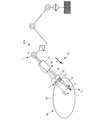
以下、本発明の第1の実施形態に係るアーム装置10ついて図1から図8を参照しながら説明する。本実施形態ではアーム装置10を、図1に示すような内視鏡外科手術に用いられる手術支援ロボットなどである例に適用して説明する。 Hereinafter, an
アーム装置10は、術具70の位置および姿勢を変更可能に支持するものである。また、アーム装置10は、術具70の位置や姿勢を変更しても、術具70がアーム装置10に対する所定の相対位置であるピボット位置Ppを通過するように制御されている。ピボット位置Ppは、内視鏡外科手術の対象である患者(被検体)80の腹壁81に配置されたトロッカー(器具)75(またはポートとも表記する。)の配置位置と概ね一致している。The
また、術具70としては、内視鏡や鉗子など、内視鏡外科手術に用いられる各種の器具を例示することができる。本実施形態では、術具70が鉗子である例について説明する。
鉗子である術具70には、図1および図2に示すように、本体部71と、筒状部72と、が主に設けられている。本体部71は、アーム装置10によって把持される部分であって、筒状部72により導かれた画像を電子信号に変換する撮像機器が収納されるものである。Examples of the
As shown in FIGS. 1 and 2, a
筒状部72は、筒状または棒状に延びる部材であって、トロッカー75に挿通されて患者の腹壁81の内部に挿入されるものである。また、筒状部72は、先端から本体部71へ画像の伝達が可能に形成されている。 The
筒状部72には、先端部73と、屈曲部74と、が設けられている。先端部73は、筒状部72における患者80に差し込まれる側の端である先端の部分である。本実施形態には先端部73に対象物を挟む構成が設けられている例に適用して説明する。 The
屈曲部74は、一方の端部が先端部73に配置され、他方の端部が筒状部72に配置される筒状または柱状に形成されたものである。また、屈曲部74は、筒状部72の伸びる方向に対して横方向へ屈曲可能な構成を有するものである。なお、屈曲部74における構成は、公知の構成を用いることができ、特に限定するものではない。 The
術具70には、更に、屈曲部74の屈曲に用いられる、ワイヤ75と、術具用空気圧アクチュエータ(術具用アクチュエータ、術具用気体圧アクチュエータ)76と、が主に設けられている。なお、本実施形態では、ワイヤ75、術具用空気圧アクチュエータ76、およびバルブ78の組が2組設けられている例に適用して説明するが、これらの組が1組であってもよいし、3組以上であってもよい。 The
ワイヤ75は、一方の端部が屈曲部74に配置され、他方の端部が術具用空気圧アクチュエータ76に配置される索状の部材であって、術具用空気圧アクチュエータ76が発生させた駆動力を屈曲部74に伝達するものである。 The
術具用空気圧アクチュエータ76は、屈曲部74を屈曲させる駆動力を発生させるものである。術具用空気圧アクチュエータ76には、ピストン76pと、シリンダ76cと、が主に設けられている。 The surgical
ピストン76pは、シリンダ76cに対して相対的に直線移動可能に配置されるものである。ピストン76pにおけるシリンダ76cから突出している部分には、ワイヤ75の一端が配置されている。また、ピストン76pに対向する領域には、ピストン76pの変位を測定するポテンショメータ79mが配置されている。 The
シリンダ76cは、両端が閉じられた筒状に形成された部材である。シリンダ76cの内部空間は、ピストン76pにより2つに区画されている。シリンダ76cには、空気供給部77から供給される昇圧された空気を、2つの区画に供給する配管が配置されている。 The
シリンダ76cと空気供給部77との間には、昇圧された空気の供給先を制御するバルブ78と、シリンダ76cの区画における空気の圧力を測定する圧力センサ79sと、が設けられている。 Between the
バルブ78は、空気供給部77から昇圧された空気が供給される行き先を制御するものである。具体的には、昇圧された空気をシリンダ76cの2つの区画のうちの一方へ供給する、または他方へ供給するかを選択するバルブである。バルブ78の形式としては公知の形式のものを用いることができる。 The
圧力センサ79sは、バルブ78とシリンダ76cとの間に配置されるものであり、2つの区画のうちの一方または他方における空気の圧力を測定するものである。測定された空気の圧力は、制御装置20へ出力される。 The
アーム装置10には、図1に示すように、回転部52と、第1リンク部55と、第2リンク部56と、ジンバル部61と、把持部65と、制御装置20と、が主に設けられている。回転部52、第1リンク部55および第2リンク部56は、アーム装置10の制御部など(図示せず)から入力される制御信号に基づいて、駆動制御されるものである。 As shown in FIG. 1, the
回転部52は、アーム装置10が土台51に固定される部分に配置される関節である。回転部52としては、上下方向に延びる回転軸線まわりに回転駆動が可能な構成であればよく、具体的な構成を限定するものではない。 The
第1リンク部55は、第1関節部62と第2リンク部56との間に配置され、アクチュエータ(図示せず)により駆動されるものである。第1リンク部55は、一対の並行なバー55bを2組有した矩形状に形成され、バー55bとバー55bとの交点は、一自由度の回転を許容するピン55pにより結合された構成を有している。本実施形態では、第1リンク部55が上下方向へ延びた姿勢に配置される例に適用して説明する。 The
第2リンク部56は、第1リンク部55とジンバル部61との間に配置され、アクチュエータ(図示せず)により駆動されるものである。第2リンク部56は、第1リンク部55と同様に、一対の並行なバー56bを2組有した矩形状に形成され、隣接する2つのバー56bは一自由度の回転を許容するピン56pにより結合された構成を有している。また、本実施形態では、第2リンク部56が横方向(上下方向と交差する面に沿った方向)へ延びた姿勢に配置される例に適用して説明する。 The
ジンバル部61は、図1に示すように、第2リンク部56と把持部65との間に配置されるものである。ジンバル部61は、回転軸線が互いに交差する第1関節部(関節)62、第2関節部(関節)63および第3関節部(関節)64と、第1気体圧アクチュエータ(アクチュエータ部)62a、第2気体圧アクチュエータ(アクチュエータ部)63a、および第3気体圧アクチュエータ(アクチュエータ部)64aと、から主に構成されている。 The
第1関節部62は、図1に示すように、第2リンク部56と隣接する位置に配置されるものである。第1関節部62は、その回転軸線が水平方向から斜め上方へ延びる姿勢に配置されている。より好ましくは、水平方向から45°の角度で斜め上方へ延びる姿勢に配置されている。 The first joint 62 is arranged at a position adjacent to the
第2関節部63は、第1関節部62と第3関節部64との間に配置されるものである。第3関節部64は、把持部65に隣接する位置に配置されるものである。なお、第1関節部62、第2関節部63および第3関節部64としては、回転軸回りの回転を可能とするものであればよく、特に限定するものではない。 The second joint 63 is arranged between the first joint 62 and the third joint 64. The third joint 64 is arranged at a position adjacent to the
第1気体圧アクチュエータ62aは、図1に示すように、第1関節部62の近傍に配置されるものであって、第1関節部62を回転駆動するとともに回転角度を制御するものである。また、第1気体圧アクチュエータ62aは、外部から供給される気体、本実施形態では空気により駆動力を発生させるものである。 As shown in FIG. 1, the first
第1気体圧アクチュエータ62aは、回転型の空気圧アクチュエータであって、第1関節部62を回転駆動するトルクを直接発生させる構成を有するものである。なお、第2気体圧アクチュエータ63aの構成としては公知の構成を用いることができ、特に構成を限定するものではない。 The first
第1気体圧アクチュエータ62aには、第1圧力センサ62sが設けられている。第1圧力センサ62sは、第1気体圧アクチュエータ62aにおける空気の圧力を測定するものである。測定された空気の圧力の値は、制御装置20の推定部21へ出力される。第1圧力センサ62sとしては、公知のセンサを用いることができ、特に限定するものではない。 The first
第2気体圧アクチュエータ63aは、第2関節部63の近傍に配置されるものであって、第2関節部63を回転駆動するとともに回転角度を制御するものである。また、第2気体圧アクチュエータ63aは、外部から供給される気体、本実施形態では空気により駆動力を発生させるものである。 The second
第2気体圧アクチュエータ63aは、回転型の空気圧アクチュエータであって、第2関節部63を回転駆動するトルクを直接発生させる構成を有するものである。なお、第2気体圧アクチュエータ63aの構成としては公知の構成を用いることができ、特に構成を限定するものではない。 The second
第2気体圧アクチュエータ63aには、第2圧力センサ63sが設けられている。第2圧力センサ63sは、第2気体圧アクチュエータ63aにおける空気の圧力を測定するものである。測定された空気の圧力の値は、制御装置20の推定部21へ出力される。第2圧力センサ63sとしては、公知のセンサを用いることができ、特に限定するものではない。 The second
第3気体圧アクチュエータ64aは、第3関節部64の近傍に配置されるものであって、第3関節部64を回転駆動するとともに回転角度を制御するものである。また、第3気体圧アクチュエータ64aは、外部から供給される気体、本実施形態では空気により駆動力を発生させるものである。 The third
第3気体圧アクチュエータ64aは、回転型の空気圧アクチュエータであって、第3関節部64を回転駆動するトルクを直接発生させる構成を有するものである。なお、第3気体圧アクチュエータ64aの構成としては公知の構成を用いることができ、特に構成を限定するものではない。 The third
第3気体圧アクチュエータ64aには、第3圧力センサ64sが設けられている。第3圧力センサ64sは、第3気体圧アクチュエータ64aにおける空気の圧力を測定するものである。測定された空気の圧力の値は、制御装置20の推定部21へ出力される。第3圧力センサ64sとしては、公知のセンサを用いることができ、特に限定するものではない。 The third
把持部65は、ジンバル部61と隣接する位置、言い換えるとアーム装置10の先端に配置されるものである。把持部65としては、術具70を把持することができる構成であればよく、具体的な構成を限定するものではない。 The
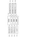
制御装置20は、アーム装置10を駆動制御するものであり、図1および図3に示すように、CPU(中央演算処理ユニット)、ROM、RAM、入出力インタフェース等を有するコンピュータ等の情報処理装置である。上述のROM等の記憶装置に記憶されているプログラムは、CPU、ROM、RAM、入出力インタフェースを協働させて、少なくとも推定部21、演算部22、および、制御部23として機能させるものである。 The
推定部21は、術具70に加えられる外力ftを推定するものである。
本実施形態では、推定部21が、少なくとも術具用空気圧アクチュエータ76における空気の圧力に基づいて、術具70に加えられる外力ftを推定する演算処理を行う例に適用して説明する。なお、推定部21による具体的な外力ftの推定方法は後述する。Estimating
In the present embodiment, a description will be given by applying to an example in which the
演算部22は、少なくとも術具70の重量W、および、推定部21により推定された外力ftに基づいて、第1気体圧アクチュエータ62a、第2気体圧アクチュエータ63a、および第3気体圧アクチュエータ64aにおいて発生させる駆動力の値を求める演算処理を行うものである。当該演算処理の具体的な内容は後述する。
なお、演算部22は、駆動力を求める際に術具70の重量Wの代わりに、術具70の質量を用いてもよい。この場合、演算部70は術具70の質量と、公知の重力加速度とを用いて重量Wを算出して、駆動力を求める演算を行う。 When calculating the driving force, the
制御部23は、演算部22により求められた駆動力の値に基づいて、第1気体圧アクチュエータ62a、第2気体圧アクチュエータ63a、および第3気体圧アクチュエータ64aにおいて発生させる駆動力を制御する処理を行うものである。制御部23における具体的な制御内容については、後述する。 The
次に、上記の構成からなるアーム装置10における制御内容について図4から図7を参照しながら説明する。
まず、制御装置20の推定部21は、図4に示すように、外力ftを推定する演算処理を行う(S11)。本実施形態では、外力ftは、患者80に挿入された術具70の先端に働く力であって、術具70と患者80との干渉や、術具70が鉗子などの可動部を有するものである場合には術具70の動作による反作用によって働く力である例に適用して説明する。Next, control contents of the
First, the
具体的には、推定部21は、術具用空気圧アクチュエータ76に配置された圧力センサ79sから出力される空気の圧力の情報(値)や、ポテンショメータ79mからピストン76pの変位の情報を取得する。次いで、取得した空気の圧力の情報や、ピストン76pの変位の情報に基づいて、外力ftを推定する演算処理を行う。ここで行われる演算処理としては、公知の演算方法を用いることができ、特に限定するものではない。Specifically, the estimating
外力ftが推定されると、制御装置20の演算部22は、駆動力の値を求める演算処理を行う(S12)。ここで駆動力は、ジンバル部61の第1気体圧アクチュエータ62a、第2気体圧アクチュエータ63aおよび第3気体圧アクチュエータ64aにおいて発生させるものである。When the external forceft is estimated, the
以下に、駆動力の値を求める演算処理について図5を参照しながら説明する。駆動力の値は、下記で説明するジンバル部61において発生させるモーメントmrに基づいて算出されるものである。なお、図5では理解を容易にするためにアーム装置10の構成を簡略化して示している。Hereinafter, the calculation processing for obtaining the value of the driving force will be described with reference to FIG. The value of the driving force is to be calculated on the basis of the moment mr to generate the
まず、各パラメータについて説明する。lは術具70の後端Prから先端Ptまでの長さである全長であり、dは術具70の後端Prからピボット位置Ppまでの長さであり、lgは術具70の後端Prから重心までの長さである。これらの値は、予め制御装置20に記憶されているものであってもよいし、公知の演算手法によって求められたものであってもよい。First, each parameter will be described. l is the total length is the length from the rear end Pr of the
なお、本実施形態では、アーム装置10における術具70を制御する際の基準点が、術具70の後端Prである例に適用して説明するが、基準点は術具70の後端Prであってもよいし、その他の位置に設定されてもよく、特に限定するものではない。In the present embodiment, a description will be given by applying to an example in which the reference point when controlling the
また、術具70の挿入方向nは、術具70の長手方向である軸線方向でもある。挿入方向nは、ピボット位置Ppの位置を表すベクトルと、術具70の後端Prの位置を表すベクトルを用いて、下記の式(1)で表される。The insertion direction n of the
具体的には、ピボット位置Ppの位置を表すベクトルから後端Prの位置を表すベクトルを引いて得られる方向ベクトルを、ピボット位置Ppの位置を表すベクトルから後端Prの位置を表すベクトルを引いた値の絶対値で割ることにより、挿入方向nが求められる。Specifically, the direction vector obtained by subtracting the vector representing the position of the rear end Pr from the vector representing the position of the pivot position Pp, the position of the rear end Pr from the vector representing the position of the pivot position Pp The insertion direction n is obtained by dividing the vector by the absolute value of the value obtained by subtracting the vector.
さらに、術具70の先端Ptは、術具70の全長lと、挿入方向nと、術具70の後端Prを用いて下記の式(2)で表される。具体的には、全長lおよび挿入方向nを掛けて得られた位置を表すベクトルに、後端Prの位置を表すベクトルを加えることにより、先端Ptの位置を表すベクトルが得られる。Furthermore, the tipP t of the
なお、ピボット位置Ppや、術具70の後端Prは、アーム装置10の回転部52、第1リンク部55、および、第2リンク部56などの回転角度等に基づいて算出される値を用いてもよいし、他の測定手法により測定された値を用いてもよい。Incidentally, the rear endP r of the pivot positionP p and,

さらに、術具70における力のつり合いは下記の式(3)で表され、モーメントのつり合いは下記の式(4)で表される。ここで、ftは、術具70の先端Ptに働く力である外力であり、fpは、術具70のピボット位置Ppに働く力である。また、frは、術具70の後端Prに働く力であり、Wは、術具70の重心に働く力である。mrは、ジンバル部61において発生させるモーメントである。Further, the balance of the force in the
式(3)は、先端Ptに働く力ftと、ピボット位置Ppに働く力fpと、後端Prに働く力frと、術具70の重心に働く力Wと、の合計が0であることを示す式であり、術具70に働く複数の力が釣り合っていることを示す式である。Equation (3), the forcef t acting on the tipP t, the forcef p acting on the pivot positionP p, the forcef r acting on the rear endP r, the force W acting on the center of gravity of the
式(4)は、先端Ptに働く力ftに起因するモーメントln×ftと、ピボット位置Ppに働く力fpに起因するモーメントlpn×fpと、術具70の重心に働く力Wに起因するモーメントlgn×Wと、ジンバル部61において発生させるモーメントmrの合計が0であることを示す式であり、術具70に働く複数のモーメントが釣り合っていることを示す式である。Equation (4), and moment ln ×f t caused by the forcef t acting on the tipP t, the center of gravity of the momentl p n ×f p and,
制御装置20の演算部22は、求める駆動力の値として、ピボット位置Ppにおける力fpが0となる値を求める演算処理を行う。具体的には、上記の式(4)におけるfpに0を代入して整理した下記の式(5)に基づいてジンバル部61において発生させるモーメントmrを算出する。
なお、ここではピボット位置Ppにおける力fpが0となる理想的な条件のもとでモーメントmrを求める例に適用して説明したが、力fpが0ではなく所定値以下となるモーメントmrを求める演算処理を行ってもよい。当該所定値は、患者80の腹壁81などに対して許容される負荷に基づいて定められる例を挙げることができる。Although the force fp is described as applied to the example of obtaining the original at the moment mr ideal conditions to be 0, the force fp is less than or equal to a predetermined value not 0 at the pivot location Pp here A calculation process forobtaining the moment mr may be performed. An example in which the predetermined value is determined based on an allowable load on the
駆動力の値が求められると、制御装置20の制御部23は、求められた駆動力の値に基づいて、ジンバル部61の第1気体圧アクチュエータ62a、第2気体圧アクチュエータ63a、および、第3気体圧アクチュエータ64aにおいて発生させる駆動力を制御する演算処理を行う(S13)。 When the value of the driving force is obtained, the
より具体的には、第1気体圧アクチュエータ62a、第2気体圧アクチュエータ63a、および、第3気体圧アクチュエータ64aにおける空気の圧力を制御する処理を行う。空気の圧力の制御方法としては、公知の方法を用いることができ、特に限定するものではない。 More specifically, a process of controlling the air pressure in the first
上記の構成のアーム装置10によれば、外部から加えられる力に従って第1関節部62、第2関節部63および第3関節部64の回動を許容する第1気体圧アクチュエータ62a、第2気体圧アクチュエータ63a、および第3気体圧アクチュエータ64aを用いるとともに、少なくとも術具70の重量Wおよび推定された外力ftに基づいて求められた駆動力の値に従って第1気体圧アクチュエータ62a、第2気体圧アクチュエータ63a、および第3気体圧アクチュエータ64aを駆動させているため、患者80に加わる負荷の軽減を図りやすくなる。According to the
つまり、アーム装置10は、術具70の重量Wおよび推定される外力ftによっては、術具70の配置位置や姿勢が変化させることなく支持する。その一方で、推定された外力ftとは別の他の力が外部から加わると、アーム装置10に支持されている術具70の配置位置や姿勢は変化する。そのため、術具70から患者80へ働く負荷の軽減が図りやすくなる。That is, the
例えば、第1気体圧アクチュエータ62a、第2気体圧アクチュエータ63a、および第3気体圧アクチュエータ64aが設けられず、外力に応じて自由に回動するジンバル部61Xである場合、言い換えると、ジンバル部61Xが受動関節である場合には、推定された外力ftとは別の他の力が外部から加わると、図6に示すように術具70の配置位置や姿勢が変化(点線で図示された術具70→実線で図示された術具70)する。すると、トロッカー75を介して術具70から腹壁81に加わる荷重が大きくなり、患者80へ働く負荷が大きくなる。For example, when the first
本実施形態のアーム装置10は、このような負荷の増大を抑制しやすくなる。ここで、別の他の力が外部から加わる場合としては、実際の外力ftが、推定された外力ftよりも大きい場合も含まれる。The
また、気体圧アクチュエータと異なり、外部から力が加わっても回動しないジンバル部61Yである場合、言い換えると、ジンバル部61Yが剛性の高い関節である場合には、図7に示すようにアーム装置10による推定された術具70の配置位置や姿勢(実線で図示)と、実際の配置位置や姿勢(点線で図示)と、に違いがあると、トロッカー75を介して術具70から腹壁81に加わる荷重が大きくなり、患者80へ働く負荷が大きくなる。 Also, unlike the pneumatic actuator, when the
駆動力の値として、術具70およびトロッカー75との間に働く力を所定値以下となる値を求めることにより、患者80に配置されたトロッカー75を介して、術具70から患者80へ働く負荷の軽減が図りやすくなる。 By obtaining a value that makes the force acting between the
術具用空気圧アクチュエータ76における空気の圧力に基づいて、術具70に加えられる外力ftを推定することにより、アーム装置10は、術具70に加えられる力(圧力センサ79sにより測定される外力)による、術具70の配置位置や姿勢の変化を抑制しやすくなる。Based on the pressure of the air in the surgical instrument for the
また、上述の実施形態では、圧力センサ79sにより測定された空気の圧力に基づいて、術具70に加えられる外力ftを推定する例に適用して説明したが、圧力センサ79sを用いることなく、術具用空気圧アクチュエータ76に供給される空気の圧力(負荷に関する情報)を取得して術具70に加えられる外力ftを推定してもよい。In the embodiment described above, based on the pressure of the air measured by the
第1気体圧アクチュエータ62a、第2気体圧アクチュエータ63a、および第3気体圧アクチュエータ64aを用いることにより、第1気体圧アクチュエータ62a、第2気体圧アクチュエータ63a、および第3気体圧アクチュエータ64aが発生させる駆動力を超える力が加えられた場合に第1関節部62、第2関節部63および第3関節部64の回動を許容しやすくなる。 By using the first
なお、上述の実施形態では、ジンバル部61に第1気体圧アクチュエータ62a、第2気体圧アクチュエータ63a、および、第3気体圧アクチュエータ64aが設けられている例に適用して説明したが、ジンバル部61に設けられるアクチュエータとしては、外部から加えられる力に従って第1関節部62、第2関節部63および第3関節部64の回動を許容するものであればよく、特にその形式などを限定するものではない。 In the above-described embodiment, the
なお、上述の実施形態では、第1気体圧アクチュエータ62a、第2気体圧アクチュエータ63a、および、第3気体圧アクチュエータ64aが回転型の空気圧アクチュエータである例に適用して説明したが、その他に図8に示す構成を有するものであってもよい。 In the above embodiment, the first
つまり、第1気体圧アクチュエータ62aは、第1シリンダ部62cと、第1ピストン部62pと、第1ワイヤ部62wと、第1弾性体部62eと、第1圧力センサ62sと、が主に設けられた構成であってもよい。 That is, the first
第1シリンダ部62cは、両端が閉じられた筒状に形成される部材である。第1シリンダ部62cの内部空間は、第1ピストン部62pにより2つに区画され、その少なくとも一方に外部から昇圧された空気が導入可能に構成されている。 The
第1ピストン部62pは、第1シリンダ部62cに対して相対的に直線移動可能に配置されるものである。また、第1ピストン部62pにおける第1シリンダ部62cから突出している部分には、第1ワイヤ部62wの一端が配置されている。 The
第1ワイヤ部62wは、第1ピストン部62pの移動を第1関節部62に伝達する索状に形成された部材である。第1ワイヤ部62wに一端は第1ピストン部62pに配置され、他端は第1弾性体部62eに配置されている。また、第1ワイヤ部62wの中央領域は、第1関節部62に巻きつけられている。 The
第1弾性体部62eは、第1ワイヤ部62wに接続されたバネなどの弾性を有する部材であり、第1ピストン部62pの移動によって、第1ワイヤ部62wが移動可能に支持するものである。第1弾性体部62eとしては公知の部材を用いることができ、特に限定するものではない。 The first
同様に、第2気体圧アクチュエータ63aは、第2シリンダ部63cと、第2ピストン部63pと、第2ワイヤ部63wと、第2弾性体部63eと、第2圧力センサ63sと、が主に設けられた構成であってもよい。第2気体圧アクチュエータ63aの第2シリンダ部63c、第2ピストン部63p、第2ワイヤ部63w、第2弾性体部63e、および、第2圧力センサ63sにおける構成は、第1気体圧アクチュエータ62aと同様であるため、その説明を省略する。 Similarly, the second
同様に、第3気体圧アクチュエータ64aに、第3シリンダ部64cと、第3ピストン部64pと、第3ワイヤ部64wと、第3弾性体部64eと、第3圧力センサ64sと、が主に設けられた構成であってもよい。第3気体圧アクチュエータ64aの第3シリンダ部64c、第3ピストン部64p、第3ワイヤ部64w、第3弾性体部64e、および、第3圧力センサ64sにおける構成は、第1気体圧アクチュエータ62aと同様であるため、その説明を省略する。 Similarly, the third
〔第2の実施形態〕
次に、本発明の第2の実施形態に係るアーム装置ついて図9および図10を参照しながら説明する。本実施形態のアーム装置の基本構成は、第1の実施形態と同様であるが、第1の実施形態とは、術具に加えられる外力ftの推定に用いられるセンサの配置位置が異なっている。よって、本実施形態においては、図9および図10を用いて当該センサに関連するものについて説明し、その他の構成等の説明を省略する。[Second embodiment]
Next, an arm device according to a second embodiment of the present invention will be described with reference to FIGS. The basic configuration of the arm device of the present embodiment is the same as the first embodiment, the first embodiment, different positions of the sensors used to estimate the external force ft exerted on the surgical instrument I have. Therefore, in the present embodiment, the components related to the sensor will be described with reference to FIGS. 9 and 10, and the description of the other components will be omitted.
本実施形態のアーム装置110における制御装置120は、図9および図10に示すように、術具70の先端Pt近傍に配置されたセンサ124に基づいて、術具70に加えられる外力ftの推定を行うものである。センサ124は、術具70の先端Pt近傍に働く力を検知する公知の方式を用いるものであって、検知方式を特に限定するものではない。センサ124により検知された術具70の先端Pt近傍に働く力の情報は、制御装置120の推定部121へ出力される。
推定部121は、術具70の先端Pt近傍に働く力に基づいて、術具70に加えられる外力ftを推定する演算処理を行うものである。例えば、センサ124が配置されている位置と、外力ftが働く位置との間の差を補正する演算処理等を行うものである。
上記の構成からなるアーム装置110における制御内容は、推定部121における術具70に加えられる外力ftを推定する演算処理が異なる点を除き、第1の実施形態のアーム装置10における制御内容と同様であるため、その説明を省略する。Control contents of the
上記の構成のアーム装置110によれば、術具70の先端Pt近傍にセンサ124を配置することにより、術具70の先端Pt近傍に働く力に基づいた駆動力の値が求められ、当該値に基づいて第1気体圧アクチュエータ62a、第2気体圧アクチュエータ63a、および、第3気体圧アクチュエータ64aの制御が行われる。そのためアーム装置110は、術具70の先端Pt近傍に加えられる力(センサ124により測定される外力)による、術具70の配置位置や姿勢の変化を抑制しやすくなる。According to the
なお、本発明の技術範囲は上記実施形態に限定されるものではなく、本発明の趣旨を逸脱しない範囲において種々の変更を加えることが可能である。例えば、上記の実施の形態において制御装置20は、アーム装置10と一体に構成されていてもよいし、アーム装置10とは別に構成されるものであってもよい。 The technical scope of the present invention is not limited to the above embodiment, and various changes can be made without departing from the spirit of the present invention. For example, in the above embodiment, the
10,110…アーム装置、21,121…推定部、22…演算部、23…制御部、62…第1関節部(関節)、63…第2関節部(関節)、64…第3関節部(関節)、62a…第1気体圧アクチュエータ(アクチュエータ部)、63a…第2気体圧アクチュエータ(アクチュエータ部)、64a…第3気体圧アクチュエータ(アクチュエータ部)、70…術具、75…トロッカー(器具)、76…術具用空気圧アクチュエータ(術具用アクチュエータ、術具用気体圧アクチュエータ)、124…センサ、ft…外力、W…重量10, 110: arm device, 21, 121: estimating unit, 22: calculating unit, 23: control unit, 62: first joint (joint), 63: second joint (joint), 64: third joint (Joint), 62a: first pneumatic actuator (actuator section), 63a: second pneumatic actuator (actuator section), 64a: third pneumatic actuator (actuator section), 70: surgical tool, 75: trocar (instrument) ), 76: pneumatic actuator for surgical tool (actuator for actuator, pneumatic actuator for surgical tool), 124: sensor,ft : external force, W: weight
Claims (8)
Translated fromJapanese前記術具の回転軸線まわりに回動することにより、前記術具の配置位置および姿勢を変化可能とする関節部と、
前記関節部を前記回転軸線まわりに回動させる駆動力を発生するとともに、外部から加えられる力に従って前記関節部の回動を許容するアクチュエータ部と、
前記術具に加えられる外力を推定する推定部と、
少なくとも前記術具の重量、および、前記推定部により推定された外力に基づいて、前記アクチュエータ部において発生させる前記駆動力の値を求める演算部と、
前記演算部により求められた前記駆動力の値に基づいて、前記アクチュエータ部において発生させる駆動力を制御する制御部と、
が設けられていることを特徴とするアーム装置。An arm device that controllably supports the arrangement position and posture of the surgical tool,
By rotating around the rotation axis of the surgical tool, an articulation portion that allows the placement position and posture of the surgical tool to be changed,
An actuator unit that generates a driving force for rotating the joint unit around the rotation axis, and allows the joint unit to rotate according to a force applied from the outside,
An estimating unit that estimates an external force applied to the surgical tool,
A calculating unit that calculates a value of the driving force generated in the actuator unit based on at least the weight of the surgical tool and the external force estimated by the estimating unit;
A control unit that controls a driving force generated in the actuator unit based on the value of the driving force obtained by the calculation unit;
An arm device characterized by comprising:
前記推定部は、前記術具用アクチュエータにおける負荷に関する情報に基づいて、前記術具に加えられる外力を推定することを特徴とする請求項1または2に記載のアーム装置。The surgical tool has a bent portion capable of bending the distal end portion, and a driving force for generating a driving force to bend the bent portion, and for a surgical tool that allows bending of the bent portion according to a force applied from the outside. An actuator is provided,
The arm device according to claim 1, wherein the estimating unit estimates an external force applied to the surgical tool based on information about a load on the surgical tool actuator.
前記推定部は、前記術具用気体圧アクチュエータにおける前記気体の圧力に基づいて、前記術具の前記先端部に加えられる外力を推定することを特徴とする請求項1または2に記載のアーム装置。The surgical instrument has a bent portion capable of bending a distal end portion, and a pneumatic actuator for a surgical tool that generates a driving force to bend the bent portion and generates a driving force by gas supplied from the outside. And are provided,
The arm device according to claim 1, wherein the estimating unit estimates an external force applied to the distal end portion of the surgical tool based on a pressure of the gas in the surgical instrument pneumatic actuator. 4. .
前記術具に加えられる外力を推定するステップと、
前記術具の重量、および、前記推定された外力に少なくとも基づいて、前記関節部を前記回転軸線まわりに回動させる駆動力を発生するとともに、外部から加えられる力に従って前記関節部の回動を許容するアクチュエータ部において発生させる前記駆動力の値を求めるステップと、
求められた前記駆動力の値に基づいて、前記アクチュエータ部において発生させる駆動力を制御するステップと、
を有することを特徴とする制御方法。A control method of an arm device that has a joint part that rotates around a rotation axis and that controls and supports an arrangement position and a posture of a surgical tool,
Estimating an external force applied to the surgical tool;
Based on at least the weight of the surgical tool and the estimated external force, a driving force for rotating the joint around the rotation axis is generated, and the rotation of the joint according to an externally applied force is performed. Obtaining the value of the driving force to be generated in the allowable actuator section;
Controlling the driving force generated in the actuator unit based on the obtained value of the driving force;
A control method comprising:
コンピュータに、
前記術具に加えられる外力を推定する機能と、
前記術具の重量、および、前記推定された外力に少なくとも基づいて、前記関節部を前記回転軸線まわりに回動させる駆動力を発生するとともに、外部から加えられる力に従って前記関節部の回動を許容するアクチュエータ部において発生させる前記駆動力の値を求める機能と、
求められた前記駆動力の値に基づいて、前記アクチュエータ部において発生させる駆動力を制御する機能と、
を実現させることを特徴とするプログラム。A program for controlling an arm device that has an articulated portion that rotates around a rotation axis and that controls and supports the arrangement position and posture of a surgical tool,
On the computer,
A function of estimating an external force applied to the surgical tool,
Based on at least the weight of the surgical tool and the estimated external force, a driving force for rotating the joint around the rotation axis is generated, and the rotation of the joint according to an externally applied force is performed. A function for determining the value of the driving force to be generated in the allowable actuator section;
A function of controlling a driving force to be generated in the actuator unit based on the obtained value of the driving force;
A program characterized by realizing.
Priority Applications (5)
| Application Number | Priority Date | Filing Date | Title |
|---|---|---|---|
| JP2018167288AJP6650153B1 (en) | 2018-09-06 | 2018-09-06 | Arm device, control method and program |
| PCT/JP2019/034771WO2020050314A1 (en) | 2018-09-06 | 2019-09-04 | Arm device, control method, and program |
| EP19858274.4AEP3725255A4 (en) | 2018-09-06 | 2019-09-04 | ARM DEVICE, CONTROL METHOD AND PROGRAM |
| CN201980024039.8ACN111936078B (en) | 2018-09-06 | 2019-09-04 | Arm device, control method, and program |
| US16/962,658US12279838B2 (en) | 2018-09-06 | 2019-09-04 | Arm device, control method, and program |
Applications Claiming Priority (1)
| Application Number | Priority Date | Filing Date | Title |
|---|---|---|---|
| JP2018167288AJP6650153B1 (en) | 2018-09-06 | 2018-09-06 | Arm device, control method and program |
Publications (2)
| Publication Number | Publication Date |
|---|---|
| JP6650153B1true JP6650153B1 (en) | 2020-02-19 |
| JP2020039434A JP2020039434A (en) | 2020-03-19 |
Family
ID=69568276
Family Applications (1)
| Application Number | Title | Priority Date | Filing Date |
|---|---|---|---|
| JP2018167288AActiveJP6650153B1 (en) | 2018-09-06 | 2018-09-06 | Arm device, control method and program |
Country Status (5)
| Country | Link |
|---|---|
| US (1) | US12279838B2 (en) |
| EP (1) | EP3725255A4 (en) |
| JP (1) | JP6650153B1 (en) |
| CN (1) | CN111936078B (en) |
| WO (1) | WO2020050314A1 (en) |
Families Citing this family (2)
| Publication number | Priority date | Publication date | Assignee | Title |
|---|---|---|---|---|
| WO2022009424A1 (en)* | 2020-07-10 | 2022-01-13 | 国立大学法人東京医科歯科大学 | Arm device |
| JP7360762B1 (en)* | 2022-03-28 | 2023-10-13 | リバーフィールド株式会社 | surgical support equipment |
Family Cites Families (11)
| Publication number | Priority date | Publication date | Assignee | Title |
|---|---|---|---|---|
| EP1915963A1 (en) | 2006-10-25 | 2008-04-30 | The European Atomic Energy Community (EURATOM), represented by the European Commission | Force estimation for a minimally invasive robotic surgery system |
| US8700213B2 (en)* | 2007-03-01 | 2014-04-15 | Tokyo Institute Of Technology | Maneuvering system having inner force sense presenting function |
| JP2010035768A (en)* | 2008-08-04 | 2010-02-18 | Olympus Medical Systems Corp | Active drive type medical apparatus |
| DE102010033326B4 (en) | 2010-08-04 | 2014-05-15 | Siemens Aktiengesellschaft | Robot, in particular for carrying out a medical treatment |
| JP5816457B2 (en)* | 2011-05-12 | 2015-11-18 | オリンパス株式会社 | Surgical device |
| JP6053342B2 (en) | 2012-06-15 | 2016-12-27 | キヤノン株式会社 | Medical manipulator and medical imaging system including the medical manipulator |
| JP5754820B2 (en)* | 2013-11-28 | 2015-07-29 | 国立大学法人東京工業大学 | Surgical robot |
| WO2017083453A1 (en) | 2015-11-12 | 2017-05-18 | Covidien Lp | Robotic surgical systems and methods for monitoring applied forces |
| JP2017104914A (en)* | 2015-12-07 | 2017-06-15 | リバーフィールド株式会社 | External force follow-up control system |
| JP7005608B2 (en)* | 2016-10-04 | 2022-02-04 | インテュイティブ サージカル オペレーションズ, インコーポレイテッド | Computer-aided remote-controlled surgical system and method |
| US10016900B1 (en) | 2017-10-10 | 2018-07-10 | Auris Health, Inc. | Surgical robotic arm admittance control |
- 2018
- 2018-09-06JPJP2018167288Apatent/JP6650153B1/enactiveActive
- 2019
- 2019-09-04USUS16/962,658patent/US12279838B2/enactiveActive
- 2019-09-04EPEP19858274.4Apatent/EP3725255A4/enactivePending
- 2019-09-04CNCN201980024039.8Apatent/CN111936078B/enactiveActive
- 2019-09-04WOPCT/JP2019/034771patent/WO2020050314A1/ennot_activeCeased
Also Published As
| Publication number | Publication date |
|---|---|
| EP3725255A4 (en) | 2021-10-06 |
| US20210361363A1 (en) | 2021-11-25 |
| US12279838B2 (en) | 2025-04-22 |
| WO2020050314A1 (en) | 2020-03-12 |
| CN111936078A (en) | 2020-11-13 |
| CN111936078B (en) | 2022-09-09 |
| JP2020039434A (en) | 2020-03-19 |
| EP3725255A1 (en) | 2020-10-21 |
Similar Documents
| Publication | Publication Date | Title |
|---|---|---|
| JP7517815B2 (en) | Tension control in actuation of multi-joint medical instruments | |
| US8644988B2 (en) | Drive force control in medical instrument providing position measurements | |
| JP6700669B2 (en) | Control method, robot device, program, recording medium, and article manufacturing method | |
| Song et al. | Shape reconstruction for wire-driven flexible robots based on Bézier curve and electromagnetic positioning | |
| JP6801901B1 (en) | Surgical robot system, external force estimation device, and program | |
| JP2016539816A (en) | Control device and tendon drive device | |
| JP6650153B1 (en) | Arm device, control method and program | |
| KR101096571B1 (en) | Force or torque measuring device of robot haptic master device and method thereof | |
| CN117814927A (en) | Data processing method and device of flexible surgical robot, robot and medium | |
| CN113474129B (en) | Surgical aids | |
| Zhang et al. | Preliminary study on magnetic tracking based navigation for wire-driven flexible robot | |
| KR20140132113A (en) | Method for compensating backlash and method for making backlash compensation value calculating formular | |
| JP2020028645A (en) | Estimation system, estimation method and program | |
| CN120382474A (en) | Control method of robotic arm, robotic system, computer device and storage medium | |
| CN120382472A (en) | Dynamic parameter calibration method of robotic arm, robot system and computer equipment | |
| CN118303982A (en) | Robot telecentric motion control method, system and storage medium based on force interaction |
Legal Events
| Date | Code | Title | Description |
|---|---|---|---|
| A621 | Written request for application examination | Free format text:JAPANESE INTERMEDIATE CODE: A621 Effective date:20191125 | |
| A871 | Explanation of circumstances concerning accelerated examination | Free format text:JAPANESE INTERMEDIATE CODE: A871 Effective date:20191125 | |
| A975 | Report on accelerated examination | Free format text:JAPANESE INTERMEDIATE CODE: A971005 Effective date:20191210 | |
| TRDD | Decision of grant or rejection written | ||
| A01 | Written decision to grant a patent or to grant a registration (utility model) | Free format text:JAPANESE INTERMEDIATE CODE: A01 Effective date:20191217 | |
| A61 | First payment of annual fees (during grant procedure) | Free format text:JAPANESE INTERMEDIATE CODE: A61 Effective date:20200115 | |
| R150 | Certificate of patent or registration of utility model | Ref document number:6650153 Country of ref document:JP Free format text:JAPANESE INTERMEDIATE CODE: R150 | |
| R250 | Receipt of annual fees | Free format text:JAPANESE INTERMEDIATE CODE: R250 | |
| S531 | Written request for registration of change of domicile | Free format text:JAPANESE INTERMEDIATE CODE: R313531 | |
| R350 | Written notification of registration of transfer | Free format text:JAPANESE INTERMEDIATE CODE: R350 |