JP6648192B2 - Tactile switches for electronic devices - Google Patents
Tactile switches for electronic devicesDownload PDFInfo
- Publication number
- JP6648192B2 JP6648192B2JP2018098487AJP2018098487AJP6648192B2JP 6648192 B2JP6648192 B2JP 6648192B2JP 2018098487 AJP2018098487 AJP 2018098487AJP 2018098487 AJP2018098487 AJP 2018098487AJP 6648192 B2JP6648192 B2JP 6648192B2
- Authority
- JP
- Japan
- Prior art keywords
- shaft
- input
- wristwatch
- button
- tactile switch
- Prior art date
- Legal status (The legal status is an assumption and is not a legal conclusion. Google has not performed a legal analysis and makes no representation as to the accuracy of the status listed.)
- Active
Links
Images


Classifications
- G—PHYSICS
- G04—HOROLOGY
- G04B—MECHANICALLY-DRIVEN CLOCKS OR WATCHES; MECHANICAL PARTS OF CLOCKS OR WATCHES IN GENERAL; TIME PIECES USING THE POSITION OF THE SUN, MOON OR STARS
- G04B27/00—Mechanical devices for setting the time indicating means
- G04B27/002—The setting apparatus being crown shaped
- G—PHYSICS
- G04—HOROLOGY
- G04G—ELECTRONIC TIME-PIECES
- G04G21/00—Input or output devices integrated in time-pieces
- G04G21/08—Touch switches specially adapted for time-pieces
- G—PHYSICS
- G06—COMPUTING OR CALCULATING; COUNTING
- G06F—ELECTRIC DIGITAL DATA PROCESSING
- G06F1/00—Details not covered by groups G06F3/00 - G06F13/00 and G06F21/00
- G06F1/16—Constructional details or arrangements
- G06F1/1613—Constructional details or arrangements for portable computers
- G06F1/163—Wearable computers, e.g. on a belt
- G—PHYSICS
- G06—COMPUTING OR CALCULATING; COUNTING
- G06F—ELECTRIC DIGITAL DATA PROCESSING
- G06F3/00—Input arrangements for transferring data to be processed into a form capable of being handled by the computer; Output arrangements for transferring data from processing unit to output unit, e.g. interface arrangements
- G06F3/01—Input arrangements or combined input and output arrangements for interaction between user and computer
- G06F3/03—Arrangements for converting the position or the displacement of a member into a coded form
- G06F3/033—Pointing devices displaced or positioned by the user, e.g. mice, trackballs, pens or joysticks; Accessories therefor
- G06F3/0362—Pointing devices displaced or positioned by the user, e.g. mice, trackballs, pens or joysticks; Accessories therefor with detection of 1D translations or rotations of an operating part of the device, e.g. scroll wheels, sliders, knobs, rollers or belts
- G—PHYSICS
- G06—COMPUTING OR CALCULATING; COUNTING
- G06F—ELECTRIC DIGITAL DATA PROCESSING
- G06F3/00—Input arrangements for transferring data to be processed into a form capable of being handled by the computer; Output arrangements for transferring data from processing unit to output unit, e.g. interface arrangements
- G06F3/01—Input arrangements or combined input and output arrangements for interaction between user and computer
- G06F3/048—Interaction techniques based on graphical user interfaces [GUI]
- G06F3/0487—Interaction techniques based on graphical user interfaces [GUI] using specific features provided by the input device, e.g. functions controlled by the rotation of a mouse with dual sensing arrangements, or of the nature of the input device, e.g. tap gestures based on pressure sensed by a digitiser
- G06F3/0488—Interaction techniques based on graphical user interfaces [GUI] using specific features provided by the input device, e.g. functions controlled by the rotation of a mouse with dual sensing arrangements, or of the nature of the input device, e.g. tap gestures based on pressure sensed by a digitiser using a touch-screen or digitiser, e.g. input of commands through traced gestures
- H—ELECTRICITY
- H01—ELECTRIC ELEMENTS
- H01H—ELECTRIC SWITCHES; RELAYS; SELECTORS; EMERGENCY PROTECTIVE DEVICES
- H01H25/00—Switches with compound movement of handle or other operating part
- H01H25/008—Operating part movable both angularly and rectilinearly, the rectilinear movement being perpendicular to the axis of angular movement
- H—ELECTRICITY
- H01—ELECTRIC ELEMENTS
- H01H—ELECTRIC SWITCHES; RELAYS; SELECTORS; EMERGENCY PROTECTIVE DEVICES
- H01H25/00—Switches with compound movement of handle or other operating part
- H01H25/06—Operating part movable both angularly and rectilinearly, the rectilinear movement being along the axis of angular movement
- H—ELECTRICITY
- H01—ELECTRIC ELEMENTS
- H01H—ELECTRIC SWITCHES; RELAYS; SELECTORS; EMERGENCY PROTECTIVE DEVICES
- H01H3/00—Mechanisms for operating contacts
- H01H3/02—Operating parts, i.e. for operating driving mechanism by a mechanical force external to the switch
- H01H3/12—Push-buttons
- H01H3/122—Push-buttons with enlarged actuating area, e.g. of the elongated bar-type; Stabilising means therefor
- H—ELECTRICITY
- H01—ELECTRIC ELEMENTS
- H01H—ELECTRIC SWITCHES; RELAYS; SELECTORS; EMERGENCY PROTECTIVE DEVICES
- H01H9/00—Details of switching devices, not covered by groups H01H1/00 - H01H7/00
- H01H9/16—Indicators for switching condition, e.g. "on" or "off"
- H—ELECTRICITY
- H01—ELECTRIC ELEMENTS
- H01H—ELECTRIC SWITCHES; RELAYS; SELECTORS; EMERGENCY PROTECTIVE DEVICES
- H01H2209/00—Layers
- H01H2209/006—Force isolators
- H—ELECTRICITY
- H01—ELECTRIC ELEMENTS
- H01H—ELECTRIC SWITCHES; RELAYS; SELECTORS; EMERGENCY PROTECTIVE DEVICES
- H01H2215/00—Tactile feedback
- H01H2215/004—Collapsible dome or bubble
- H01H2215/006—Only mechanical function
- H—ELECTRICITY
- H01—ELECTRIC ELEMENTS
- H01H—ELECTRIC SWITCHES; RELAYS; SELECTORS; EMERGENCY PROTECTIVE DEVICES
- H01H2221/00—Actuators
- H01H2221/008—Actuators other then push button
- H01H2221/01—Actuators other then push button also rotatable
- H—ELECTRICITY
- H01—ELECTRIC ELEMENTS
- H01H—ELECTRIC SWITCHES; RELAYS; SELECTORS; EMERGENCY PROTECTIVE DEVICES
- H01H2223/00—Casings
- H01H2223/002—Casings sealed
Landscapes
- Engineering & Computer Science (AREA)
- Theoretical Computer Science (AREA)
- General Engineering & Computer Science (AREA)
- Physics & Mathematics (AREA)
- General Physics & Mathematics (AREA)
- Human Computer Interaction (AREA)
- Computer Hardware Design (AREA)
- Switch Cases, Indication, And Locking (AREA)
- Switches With Compound Operations (AREA)
- User Interface Of Digital Computer (AREA)
- Electric Clocks (AREA)
- Push-Button Switches (AREA)
- Measuring And Recording Apparatus For Diagnosis (AREA)
Description
Translated fromJapanese本開示は、全般的に電子デバイスに関し、より詳細には、コンピューティングデバイス用の入力デバイスに関する。 The present disclosure relates generally to electronic devices, and more particularly, to input devices for computing devices.
(関連出願の相互参照)
特許協力条約に基づく本出願は、2013年8月9日に出願され、「Tactile Switch for an Electronic Device」と題された、米国仮特許出願第61/864,389号に対する優先権を主張するものであり、その内容は、参照により全体が本明細書内に組み込まれる。(Cross-reference of related applications)
This application under the Patent Cooperation Treaty claims priority to US Provisional Patent Application No. 61 / 864,389, filed August 9, 2013, entitled "Tactile Switch for an Electronic Device." , The contents of which are incorporated herein by reference in their entirety.
スマートフォン、ゲーム機、コンピュータ、腕時計などの、多くのタイプの電子デバイスは、ボタン又はスイッチなどの入力デバイスを使用して、ユーザ入力を受け取る。しかしながら、ボタン又はスイッチなどの多くの入力デバイスは、単一のタイプの入力のみを可能とする場合がある。例えば、ボタンは、回路を完成させるボタンの圧迫である、1つのタイプの信号のみを伝達することができる。電子デバイスのサイズが縮小するにつれ、デバイスに情報を提供するためにユーザによって使用することが可能な入力のタイプの、機能性又は数を低減することなく、より少ない入力ボタン又は入力デバイスを有することが、望ましい場合がある。更には、ボタン又はスイッチが、移動可能若しくは回転可能であり得る実例では、その移動により、電気的接続が困難となる恐れがあるため、そのボタンは、ボタンと電子デバイスの1つ以上の構成要素との間で、データ及び/又は電力を転送することを必要とする、センサ若しくは他の電子的要素を含むことが不可能となる場合がある。 Many types of electronic devices, such as smartphones, game consoles, computers, watches, etc., receive user input using input devices such as buttons or switches. However, many input devices, such as buttons or switches, may allow only a single type of input. For example, a button may transmit only one type of signal, which is the compression of the button completing a circuit. As the size of electronic devices decreases, having fewer input buttons or devices without reducing the functionality or number of types of inputs that can be used by a user to provide information to the device However, it may be desirable. Further, in instances where the button or switch may be movable or rotatable, the movement may make electrical connection difficult, such that the button may be one or more components of the electronic device. In some cases, it may not be possible to include sensors or other electronic components that require data and / or power to be transferred between the two.
本開示の一実施例は、入力モジュールの形態を取る。この入力モジュールは、スイッチと、そのスイッチに動作可能に接続され、そのスイッチを作動させるように構成された、回転可能かつ平行移動可能な入力部材と、そのスイッチに動作可能に接続され、入力部材と電気連通する、電気接点とを含む。動作中は、入力部材と電気接点との電気的接続は、入力部材の平行移動及び回転の間、維持される。この入力モジュールは、様々な電子デバイスと共に使用することができ、それらのデバイスに入力を提供するために、ユーザによって使用することができる。 One embodiment of the present disclosure takes the form of an input module. The input module includes a switch, a rotatable and translatable input member operably connected to the switch and configured to operate the switch, and an input member operably connected to the switch. And an electrical contact in electrical communication with the In operation, the electrical connection between the input member and the electrical contacts is maintained during translation and rotation of the input member. This input module can be used with a variety of electronic devices and can be used by a user to provide input to those devices.
本開示の別の実施例は、スイッチアセンブリの形態を取る。このスイッチアセンブリは、回転可能かつ平行移動可能な入力部材と、その入力部材に動作可能に接続され、入力部材と共に移動可能である、結合部と、その結合部に動作可能に接続されたタクタイル(tactile)スイッチと、そのタクタイルスイッチに動作可能に接続され、結合部と電気連通する、電気接点とを含む。入力部材は、その入力部材が平行移動する場合に、電気構成要素を作動させるように構成され、結合部は、入力部材が回転する際に回転する。更には、結合部と電気接点との電気的接続は、入力部材の平行移動及び回転の間、維持される。 Another embodiment of the present disclosure takes the form of a switch assembly. The switch assembly includes a rotatable and translatable input member, a coupling operably connected to the input member and movable with the input member, and a tactile operably connected to the coupling. tactile) switch and electrical contacts operably connected to the tactile switch and in electrical communication with the coupling. The input member is configured to activate the electrical component when the input member translates, and the coupling rotates as the input member rotates. Further, the electrical connection between the coupling and the electrical contacts is maintained during translation and rotation of the input member.
本開示の更に別の実施例は、ウェアラブル電子デバイスを含む。このウェアラブル電子デバイスは、エンクロージャを含み、このエンクロージャは、空洞部、及びそのエンクロージャを貫通して画定されるボタン開口を画定する。このウェアラブル電子デバイスはまた、空洞部内部に受容された1つ以上の処理要素、及びエンクロージャに動作可能に接続されたスイッチモジュールも含む。このスイッチモジュールは、処理要素と通信するタクタイルスイッチと、そのタクタイルスイッチに動作可能に接続された、回転可能かつ平行移動可能な入力部材と、そのタクタイルスイッチに動作可能に接続され、入力部材に電気的に結合された、接点とを含む。動作中は、入力部材と接点との電気的結合は、入力部材の平行移動及び回転の間、維持される。 Yet another embodiment of the present disclosure includes a wearable electronic device. The wearable electronic device includes an enclosure, the enclosure defining a cavity and a button opening defined therethrough. The wearable electronic device also includes one or more processing elements received within the cavity, and a switch module operably connected to the enclosure. The switch module includes a tactile switch in communication with the processing element, a rotatable and translatable input member operably connected to the tactile switch, and an operably connected to the tactile switch, and electrically connected to the input member. And contacts that are operatively coupled. In operation, the electrical connection between the input member and the contacts is maintained during translation and rotation of the input member.
(概要)
本開示の一部の実施形態は、タクタイル(tactile)スイッチアセンブリを含む。このタクタイルスイッチアセンブリは、幾つかの電子デバイス内に実装することができる。一部の実施形態では、タクタイルスイッチアセンブリは、ウェアラブル電子デバイス、ラップトップコンピュータ、タブレットなどの、ポータブル電子デバイス内に組み込むことができる。ウェアラブル電子デバイスは、腕時計、ポータブル音楽プレーヤ、コンピューティング又はゲーム機、スマートフォンなどとすることができる。一部の実施形態では、ウェアラブル電子デバイスは、ユーザの手首の周りに装着することが可能な、腕時計である。これらの実施形態では、タクタイルスイッチアセンブリは、腕時計に関する竜頭を形成し、そのデバイスに関するエンクロージャの側壁に接続される、ボタンを含み得る。(Overview)
Some embodiments of the present disclosure include a tactile switch assembly. This tactile switch assembly can be implemented in some electronic devices. In some embodiments, the tactile switch assembly can be incorporated into a portable electronic device, such as a wearable electronic device, laptop computer, tablet, and the like. The wearable electronic device can be a watch, a portable music player, a computing or gaming device, a smartphone, and the like. In some embodiments, the wearable electronic device is a watch that can be worn around the user's wrist. In these embodiments, the tactile switch assembly may include a button that forms a crown for the watch and is connected to a sidewall of the enclosure for the device.
タクタイルスイッチアセンブリは、タクタイルスイッチ、ユーザ入力部材、及びシアプレート若しくは電気接点を含む。ボタン、スイッチ、フランジなどとすることが可能なユーザ入力部材は、タクタイルスイッチに対する第1のタイプの入力を、そのスイッチを機械的にアクティブ化させることによって提供することができる。例えば、タクタイルスイッチは、入力ボタンに対する平行移動するユーザの力により圧縮する、ドームを含み得るものであり、圧縮時に、そのタクタイルスイッチは、ユーザ入力を示す信号を生成する。この実施例では、ドームの圧縮はまた、ユーザに対するフィードバック、例えば、触覚フィードバックも提供することができる。 The tactile switch assembly includes a tactile switch, a user input member, and a shear plate or electrical contact. User input members, which can be buttons, switches, flanges, etc., can provide a first type of input to a tactile switch by mechanically activating the switch. For example, a tactile switch may include a dome that compresses with the translational user's force on an input button, and upon compression, the tactile switch generates a signal indicating user input. In this embodiment, compression of the dome can also provide feedback to the user, for example, tactile feedback.
シアプレートは、タクタイルスイッチとユーザ入力ボタンとの間、及び/又はタクタイルスイッチとユーザ入力ボタン上の1つ以上の電気構成要素(例えば、センサ)との間で、電気信号が伝送可能となるように、タクタイルスイッチとユーザ入力ボタンとを電気的に接続することができる。他の実施形態では、シアプレート及びボタンに取り付けられた、コード、ワイヤ、配線、若しくは他の電気的要素によって、スイッチとボタンとの間で、電気信号、電力などをルーティングすることができる。シアプレートはまた、タクタイルスイッチに剪断力が伝達されることを防ぎ、タクタイルスイッチが損傷を受けることを防ぐ役割も果たす。ユーザ入力ボタンはまた、タクタイルスイッチアセンブリに対する、第2のタイプの入力も提供することができる。例えば、このユーザ入力部材は、タクタイルスイッチに対して回転可能とすることができる。引き続きこの実施例では、タクタイルスイッチとユーザ入力ボタンとの間に、シアプレートを位置決めすることにより、ユーザ入力部材がシアプレートに対して回転される際であっても、ユーザ入力部材は、シアプレートとの通信を維持することが可能となり得る。例えば、シアプレートは、ユーザ入力ボタンが回転される際に、ユーザ入力部材との電気的接続を維持する、ブラシ接点を含み得る。 The shear plate allows electrical signals to be transmitted between the tactile switch and a user input button and / or between the tactile switch and one or more electrical components (eg, sensors) on the user input button. In addition, the tactile switch and the user input button can be electrically connected. In other embodiments, cords, wires, wires, or other electrical elements attached to the shear plate and the buttons can route electrical signals, power, etc. between the switches and the buttons. The shear plate also serves to prevent shear forces from being transmitted to the tactile switch and to prevent damage to the tactile switch. The user input buttons may also provide a second type of input to the tactile switch assembly. For example, the user input member can be rotatable with respect to the tactile switch. Continuing, in this embodiment, by positioning the shear plate between the tactile switch and the user input button, the user input member will be able to move the shear plate It may be possible to maintain communication with. For example, the shear plate may include brush contacts that maintain an electrical connection with the user input member when the user input button is rotated.
一部の実施形態では、タクタイルスイッチアセンブリは、生理的センサとして使用することができ、かつ/又は生体認証センサと関連して使用することができるが、このセンサは、特定の実施形態からは省略することができる点を理解されたい。特定の実施形態では、このウェアラブル電子デバイスを使用して、心拍数、心臓の電気的活動などの、ユーザの身体の電気的パラメータを測定することができる。一実施例としては、タクタイルスイッチアセンブリを使用して、ユーザの心電図記録を捕捉することができる。この実施例では、ウェアラブルデバイスは、第1のユーザ接触位置を含み得るものであり、ユーザ入力ボタンは、ユーザによって接触される場合に、第2のユーザ接触位置を形成し得る。この実施形態では、ユーザの心拍数をデバイスが感知することを可能にする、ユーザとデバイスとの間の電路を、それらの2つの接触により作り出すことができる。これらの実施形態では、シアプレート上の接点が、導電性である場合があり、及び/又は、タクタイルスイッチ自体が、ボタンと相互作用するための、導電性突起若しくは接触点を含む場合がある。これらの実施形態により、筐体内部の1つ以上の要素に、タクタイルスイッチを電気的に接続することが可能となる。 In some embodiments, the tactile switch assembly can be used as a physiological sensor and / or can be used in conjunction with a biometric sensor, but this sensor is omitted from certain embodiments. Please understand what you can do. In certain embodiments, the wearable electronic device can be used to measure electrical parameters of the user's body, such as heart rate, cardiac electrical activity, and the like. As one example, a tactile switch assembly can be used to capture a user's electrocardiographic recordings. In this example, the wearable device may include a first user touch location, and the user input button may form a second user touch location when touched by a user. In this embodiment, an electrical path between the user and the device that allows the device to sense the user's heart rate can be created by those two contacts. In these embodiments, the contacts on the shear plate may be conductive and / or the tactile switch itself may include conductive protrusions or points of contact for interacting with the buttons. These embodiments allow the tactile switch to be electrically connected to one or more elements inside the housing.
一部の実施形態では、タクタイルスイッチアセンブリはまた、ユーザ入力ボタン上の、若しくはユーザ入力ボタン内に組み込まれた、1つ以上の感知要素及び/又は入出力要素も含み得る。通信構成要素は、ウェアラブルデバイスの1つ以上の内部構成要素に、ユーザ入力ボタンを電気的に接続するため、これらのユーザ入力ボタン上のセンサ及び/又は他の電子構成要素は、シアプレートと通信することができ、それらのセンサ及び/又は他の構成要素からの信号は、ユーザ入力ボタンから、シアプレート上の電気接点を介して、1つ以上の処理要素に送信することができる。一部の実施形態では、ワイヤ、コード、配線、又は他の電気的要素により、シアプレートとユーザ入力ボタンなどの入出力要素とを、電気的に接続することができる。 In some embodiments, the tactile switch assembly may also include one or more sensing elements and / or input / output elements incorporated on or within the user input buttons. The communication components electrically connect the user input buttons to one or more internal components of the wearable device, such that sensors and / or other electronic components on these user input buttons communicate with the shear plate. And signals from those sensors and / or other components can be transmitted from a user input button to one or more processing elements via electrical contacts on the shear plate. In some embodiments, wires, cords, wires, or other electrical elements can electrically connect the shear plate and input / output elements, such as user input buttons.
タクタイルスイッチアセンブリは、限定するものではないが、回転入力、平行移動入力、及び/又は電気的入力などの、複数のタイプのユーザ入力を受け取るように構成することができる。例えば、一実施形態では、タクタイルスイッチアセンブリは、シアプレートを含み得るものであり、タクタイルスイッチに損傷を与えることなく、回転入力並びに平行移動入力を受け取るように構成することができる。更には、又は代替的に、タクタイルスイッチアセンブリは、入力部材が移動される(例えば、平行移動及び/又は回転される)際であっても、電子デバイス内部の1つ以上の構成要素と電気連通することができる。これらの実施例では、回転入力が所望されない場合には、又は回転入力が制限される場合には、シアプレートを省略することができ、タクタイルスイッチ自体が、導電性突起などの、導電性接点を含み得る。 The tactile switch assembly can be configured to receive multiple types of user input, such as, but not limited to, a rotary input, a translation input, and / or an electrical input. For example, in one embodiment, the tactile switch assembly may include a shear plate and may be configured to receive rotational as well as translational inputs without damaging the tactile switch. Additionally or alternatively, the tactile switch assembly is in electrical communication with one or more components inside the electronic device even when the input member is moved (eg, translated and / or rotated). can do. In these embodiments, if rotational input is not desired or if rotational input is limited, the shear plate may be omitted and the tactile switch itself may be provided with conductive contacts, such as conductive protrusions. May be included.
ここで図を参照すると、例示的なウェアラブル電子デバイスが、より詳細にここで論じられる。図1は、ウェアラブル電子デバイスの上部平面図である。図2は、図1のウェアラブル電子デバイスの簡略ブロック図である。図1及び図2を参照すると、ウェアラブル電子デバイス100は、ハブ102又はコンピューティングセンターを含み得る。電子デバイス100が、ユーザによって装着されるように構成される実施形態では、デバイス100は、ハブ102の対向側部に接続することが可能な、1つ以上のストラップ104、106を含み得る。ストラップ104、106のそれぞれを、手首、腕、脚、胸、又はユーザの身体の他の部分に巻き付けることにより、ハブ102をユーザに固定することができる。例えば、ストラップ104、106のそれぞれの端部を、締結機構108によって一体に接続することができる。締結機構108は、限定するものではないが、フックアンドループ、磁気締結具、スナップ、ボタン、留め金などの、実質的に任意のタイプの締結デバイスとすることができる。しかしながら、図1に示すものなどの一実施形態では、締結機構108は、第2のストラップ106内の1つ以上の開口112内に挿入することにより、第1のストラップ104と第2のストラップ106とを一体に固定することが可能な、爪部134又は要素を含む、バックルである。 Referring now to the figures, an exemplary wearable electronic device will now be discussed in more detail. FIG. 1 is a top plan view of a wearable electronic device. FIG. 2 is a simplified block diagram of the wearable electronic device of FIG. Referring to FIGS. 1 and 2, wearable
このウェアラブル電子デバイスのハブ102は、一般的に、ウェアラブル電子デバイス100のコンピューティング要素及び処理要素を収容する。図3は、図1での線3−3に沿った、ハブ102の部分断面図である。図1〜図3を参照すると、ハブ102は、エンクロージャ114によって少なくとも部分的に取り囲まれた、ディスプレイ116を含み得る。一部の実施形態では、ディスプレイ116は、ハブ102のフェース部を形成し得るものであり、エンクロージャ114は、ディスプレイ116の縁部及び裏面を包み込むことができる。更には、エンクロージャ114の内部の、ディスプレイ116とエンクロージャ114との間に、ウェアラブルデバイス100の内部構成要素を収容することができる。エンクロージャ114は、ハブ102の内部構成要素を防護するとともに、ディスプレイ116をハブ102に接続する。 The wearable
エンクロージャ114は、限定するものではないが、プラスチック、金属、合金などの、様々な材料から構築することができる。エンクロージャ114は、タクタイルスイッチアセンブリ110又はその一部分を受容するための、ボタン開口172(図3を参照)を含む。ボタン開口172は、エンクロージャ114の側壁188内部にチャネルを形成し、エンクロージャ114の外側表面188から内側表面190へと延在する。ボタン開口172は、一般的に、タクタイルスイッチアセンブリ110のボタンに対応するように構成される。しかしながら、ボタン開口172は、他の方式で成形及びサイズ決定することもできる。
図3を参照すると、一部の実施形態では、エンクロージャ114は、ボタン開口172の内側を覆う、スリーブ220を含み得る。これらの実施形態では、スリーブ220内に、タクタイルスイッチアセンブリのボタン及び/又は他の部分を受容することができ、このスリーブ220が、エンクロージャ114にタクタイルスイッチアセンブリ110を接続する。スリーブ220は、エンクロージャ114の空洞部139を封止することを助けるとともに、タクタイルスイッチアセンブリの1つ以上の構成要素を、エンクロージャに固定することを助ける役割を果たし得る。一部の実施形態では、スリーブ220は、絶縁材料とすることができ、タクタイルスイッチ、あるいは、ヘッド部及び結合部などの、タクタイルスイッチの諸部分を、エンクロージャから絶縁することができる。以下でより詳細に論じられるように、このことにより、タクタイルスイッチアセンブリは、ユーザの心拍数などの、ユーザの身体の1つ以上の特性を測定することが可能となり得る。 Referring to FIG. 3, in some embodiments, the
エンクロージャ114はまた、ディスプレイ116を受容するように上部表面上に画定された、溝186も含み得る。図1及び図3を参照すると、ディスプレイ116は、接着剤又は他の締結機構を通じて、エンクロージャ114に接続することができる。この実施例では、ディスプレイは、エンクロージャの陥凹部分又は溝の内部に着座しており、そのディスプレイの縁部を、エンクロージャが包み込む。しかしながら、他の実施形態では、ディスプレイ及びエンクロージャは、他の方式で一体に接続することができる。
ディスプレイ116は、ウェアラブルデバイス100に視覚出力を提供することが可能な、実質的に任意のタイプの表示スクリーン又は表示デバイスとすることができる。一実施例として、ディスプレイ116は、液晶ディスプレイ、発光ダイオードディスプレイなどとすることができる。更には、ディスプレイ116はまた、容量性感知要素を通じてユーザ入力を受け取る、マルチタッチ表示スクリーンのように、ユーザ入力を受け取るように構成することもできる。多くの実施形態では、ディスプレイ116は、動的に変化可能とすることができるが、しかしながら、他の実施形態では、ディスプレイ116は、動的に変化し得ない、塗装されたフェースプレートなどの、非電子構成要素とすることができる。
ディスプレイ116は、選択的に変更可能な、複数のアイコン118、120又は他のグラフィックを含む。一実施例として、第1のグラフィック118は、その文字を変化させることにより時間変化を表現する、時間グラフィック、例えば、時間、分、及び秒を表現するための数字を含み得る。第2のグラフィック120は、バッテリ寿命、メッセージの受信などの、通知グラフィックを含み得る。2つのグラフィック118、120は、ディスプレイ116上の、実質的に任意の場所に位置決めすることができ、所望により変更することができる。更には、グラフィック118、120の数、サイズ、形状、及び他の特性も、同様に変化させることができる。
タクタイルスイッチアセンブリ110は、エンクロージャ114に動作可能に接続される。タクタイルスイッチアセンブリ110は、以下でより詳細に論じられるが、全般的に、ユーザがウェアラブル電子デバイス100に入力を提供することを可能にするとともに、ユーザに触覚フィードバックを提供することもできる。
図2を参照すると、このウェアラブル電子デバイスは、複数の処理要素又はコンピューティング要素を含む。例えば、ウェアラブル電子デバイス100は、電源122、1つ以上の処理要素124、メモリ構成要素128、1つ以上の任意選択的センサ126、及び入出力構成要素130を含み得る。これらの内部構成要素のそれぞれは、エンクロージャ114内部に受容することができ、1つ以上のシステムバス132、配線、プリント回路板、又は他の通信機構を通じて、通信することができる。 Referring to FIG. 2, the wearable electronic device includes a plurality of processing or computing elements. For example, the wearable
電源122は、ハブ102、及びウェアラブルデバイス100の他の構成要素に、電力を提供する。電源122は、バッテリ、又は他のポータブル電力要素とすることができる。更には、電源122は、再充電可能又は交換可能とすることができる。
処理要素124又はプロセッサは、命令を受信及び実行することが可能な、実質的に任意のタイプのデバイスである。例えば、処理要素124は、プロセッサ、マイクロコンピュータなどとすることができる。更には、処理要素124は、1つ以上のプロセッサを含み得るものであり、一部の実施形態では、複数の処理要素を含み得る。
1つ以上のセンサ126は、ウェアラブル電子デバイス100の1つ以上の動作に影響を及ぼすように使用することが可能な、幾つもの異なるパラメータ又は特性を感知するように構成することができる。例えば、センサ126は、加速度計、ジャイロスコープ、容量センサ、光センサ、画像センサ、圧力又は力センサなどを含み得る。以下でより詳細に論じられるように、センサ126のうちの1つ以上を、タクタイルスイッチアセンブリ110と共に、又はタクタイルスイッチアセンブリ110と別個に使用して、ハブ102にユーザ入力を提供することができる。特定の実施形態では、1つ以上のセンサ126を省略することができる。 One or
引き続き図2を参照すると、メモリ構成要素128は、ウェアラブルデバイス100によって利用することが可能な、電子データを記憶する。例えば、メモリ構成要素128は、様々なアプリケーションに対応する、電気的データ又はコンテンツ、例えば、オーディオファイル、ビデオファイル、文書ファイルなどを記憶することができる。メモリ128は、例えば、不揮発性記憶装置、磁気記憶媒体、光学記憶媒体、光磁気記憶媒体、読み出し専用メモリ、ランダムアクセスメモリ、消去可能プログラマブルメモリ、又はフラッシュメモリとすることができる。 With continued reference to FIG. 2,
入出力インタフェース130は、ユーザ又は1つ以上の他の電子デバイスから、データを受信することができる。更には、入出力インタフェース130は、ユーザ又は他の電子デバイスへのデータの送信を容易にすることができる。例えば、入出力インタフェース130は、ネットワークからデータを受信するために使用することができ、又は、無線若しくは有線接続(幾つかの例としては、インターネット、WiFi(登録商標)、Bluetooth(登録商標)、及びEthernet(登録商標))を介して、電子信号を送信及び伝送するために使用することができる。一部の実施形態では、入出力インタフェース130は、複数のネットワーク又は通信機構をサポートすることができる。例えば、ネットワーク/通信インタフェース130は、Bluetoothネットワークを介して別のデバイスとペアリングすることにより、その他方のデバイスに信号を転送すると同時に、WiFi又は他のネットワークから、データを受信することができる。 The input /
ここでタクタイルスイッチアセンブリ110を、より詳細に論じる。タクタイルスイッチアセンブリ110は、ボタン148、結合部218、シアプレート156、及びタクタイルスイッチ214を含み得る。これらのタクタイルスイッチの構成要素は、動作可能に一体に接続することができ、選択構成要素は、互いに電気連通することができる。
図3を参照すると、ボタン148は、タクタイルスイッチアセンブリ110に関するユーザインタフェースを形成し、エンクロージャ114から外向きに延在する。例えば、ボタン148は、筐体に対して平行移動可能及び/又は回転可能な、ボタン若しくはスイッチなどの、入力部材とすることができる。エンクロージャに対して平行移動及び回転する、ボタン148の能力により、ユーザは、タクタイルスイッチアセンブリに、回転力及び/又は平行移動力を提供することが可能となる。一部の実施形態では、ボタン148は、ウェアラブル電子デバイス100に関する竜頭を形成することができ、他の実施形態では、ボタン148は、この電子デバイスに関する入力ボタン又はスイッチを形成することができる。ボタン148は、一般的に、円筒形の本体と、丸みを帯びた頂部又は平坦な頂部とを有する、フランジ形状の部材とすることができる。ボタン148は、ユーザ入力を受け取るように構成された外側表面232、及び、ボタン148の内部表面234から延在するステム150を含む。ステム150は、ステム150の長さ、又は長さの一部分に沿って長手方向に延在する、結合部開口236を画定することができる。換言すれば、ステム150は、中空又は部分的に中空とすることができる。一部の実施形態では、ボタン148及び/又はステム150は、導電性材料で作製することができ、及び/又は、導電性材料を混入若しくは添加することができる。 Referring to FIG. 3,
引き続き図3を参照すると、結合部218は、タクタイルスイッチ214にボタン148を機械的及び/又は電気的に結合する、シャフトなどのリンク機構とすることができる。結合部218は、ボタン148と一体に形成することができ、又は、ボタン148に動作可能に接続された、別個の構成要素とすることもできる。例えば、ボタン148のステム150は、そのボタンと一体に形成された、結合部材を形成することができる。結合部218は、1種以上の金属又は合金などの、導電性材料で作製することができる。この導電特性により、結合部218は、タクタイルスイッチ214及びシアプレート156に、ボタン148を電気的に結合する役割を更に果たし得るが、他の実施形態では、そのような電気的接続内にシアプレートを含むか否かにかかわらず、ワイヤ、コード、又は他の回路により、ボタンとスイッチとを電気的に結合することができる。この結合部はまた、その底部表面上に、グラファイトなどの低摩擦材料も含み得るものであり、このことにより、結合部は、シアプレートと動作可能に関連付けられる場合であっても、より容易に回転することが可能となる。 With continued reference to FIG. 3,
結合部218は、底端部222から延在する、シャフト240を含み得る。底端部222は、シャフト240よりも大きい直径を有し得る。底端部222は、外側表面の周りに延在する、環状棚部228を含み得る。環状棚部228は、エンクロージャ114及び/又はスリーブ220の内側表面に対して封止するように構成することができる。更には、環状棚部228は、追跡可能要素146、センサ、又は封止部材を、結合部218に固定するように構成することができる。 The
結合部218の底端部222は、シアプレート156に結合部218を動作可能に接続するための、接合部を形成する。これらの実施形態では、結合部218は、底端部222に接続された、係合特徴部226を含み得る。係合特徴部226は、シアプレート156に回転可能に接続して、結合部が回転又は静止している間に、シアプレート156に対する電気的接続を維持するように構成されるが、このことは、以下でより詳細に論じられる。図3に示すように、一実施形態では、係合特徴部226は、底端部222の底部表面244内に形成された、陥凹部224を含む。環状壁242が、底部表面244から延在して、陥凹部224を取り囲む。 The
引き続き図3を参照すると、結合部218とタクタイルスイッチ214との間に、シアプレート156を位置決めすることができる。一部の実施形態では、シアプレート156は、タクタイルスイッチ214と一体化させることができ、その一実施例が図10に示される。図3に示されるものなどの、他の実施形態では、シアプレート156は、タクタイルスイッチ214に動作可能に接続された、別個の構成要素とすることができる。以下でより詳細に論じられるように、シアプレート156は、結合部からの剪断力が、タクタイルスイッチ214に伝達されることを、実質的に防ぐことができる。 With continued reference to FIG. 3, a
シアプレート156は、本体部250から上向きに延在する、電気接点158を含み得る。電気接点158は、導電性材料であるか、又は他の方式で導電性材料が混入されていることにより、電気接点158は、電気信号を伝送することができる。本体部250は、プレートとして成形することができ、あるいは他の方式で、タクタイルスイッチ214の長さ及び/又は幅にわたって延在するように構成することができる。シアプレート156は、少なくとも部分的に剛性として、結合部218からの力を、タクタイルスイッチ214に伝達するように構成することができるが、このことは、以下でより詳細に論じられる。更には、シアプレート156は、処理要素124及び/又は電源に、電気接点158を接続するための、1つ以上の端子又は接続機構を含み得る。
タクタイルスイッチ214は、突起216及び陥没可能なドーム252を含み得る。突起216は、ドーム252の内部上の接触要素と相互作用することにより、スイッチセンサ160がアクティブ化している場合を示す。例えば、接触要素168が、スイッチの底部に接触すると、回路を完成することができ、信号を刺激又は生成することなどができる。ドーム252は、既定の力レベルで陥没又は屈曲し、力が除去されるとその本来の形状に復帰する、弾性かつ可撓性の材料である。ドーム252は、薄い金属のドーム、プラスチックのドーム、又は、他の材料から構築することが可能な、他のものとすることができる。ドーム252は、ユーザによって加えられた陥没力に応答して、可聴音並びに反力を生じさせることができる。この可聴音及び反力は、ユーザがドーム252を圧縮する際、ユーザに対するフィードバックを提供する。突起216は、ドーム252に接続され、突起216に力が適用されると、突起216が、ドーム252を陥没させる。
一部の実施形態では、ウェアラブル電子デバイスは、追跡可能要素146及び感知要素142を含み得る。感知要素142は、ボタン148に対する入力を検出するために、追跡可能要素146を検出するように構成される。例えば、一部の実施形態では、ボタン148(又は、他のボタン)は、第1の入力を提供するために回転可能、かつ第2の入力を提供するために圧縮可能とすることができる。この実施例では、感知要素142は、結合部218及び/又はステム150に取り付けることが可能な、追跡可能要素146の位置を追跡することによって、回転入力を感知することができる。一実施例として、追跡可能要素146は、磁気要素とすることができ、感知要素142は、追跡可能要素146の回転を追跡するために使用することが可能な、1つ以上のホール効果センサなどの、磁場センサを含み得る。更に別の選択肢として、回転は、光学的に感知することができる。追跡可能要素146は、明暗のマーク、ストライプなどの連続、セット、若しくは他のパターン、又は反射率、光沢などが変化する区域などの、一定のパターンとすることができる。感知要素142は、光源(図示せず)によって生成され、追跡可能要素から反射された光を、受光することができる。この反射光は、追跡可能要素のパターンによって変化し得るため、その反射光を感知することができ、その光が入射した追跡可能要素のパターンを、判定することができる。それゆえ、追跡可能要素のパターンが、その表面に沿って十分に固有のものである場合には、そのボタン入力を感知することができる。更に別の選択肢として、追跡可能要素のパターンは、追跡可能要素の外周に沿って変化し得るものであり、追跡可能要素は、シャフト240が回転する際に回転することができる。それゆえ、シャフトの回転位置を、追跡可能要素146から判定することができる。更に別の選択肢として、追跡可能要素は、シャフト自体の上に組み込まれる場合があり、別個の部品ではない場合がある。すなわち、特定の実施形態では、シャフトには、上述のようにマークを付けることができる。 In some embodiments, the wearable electronic device may include a
タクタイルスイッチアセンブリ110は、任意選択的に、ボタン148内部に位置決めされるか、又はボタン148に接続される、1つ以上のセンサ126を更に含み得る。センサ126は、ボタン148内部の1つ以上のワイヤ若しくは経路を介して、又はボタン148を導電性材料とすることが可能な実例で、結合部218に電気的に接続することができる。センサ126は、1つ以上の特性を感知し、結合部218を介して、処理要素124にデータを中継するように構成することができる。
図3を参照すると、ウェアラブル電子デバイス100内部でのタクタイルスイッチアセンブリ110の組み立てが、ここでより詳細に論じられる。タクタイルスイッチ214は、ウェアラブルデバイス100の空洞部139内部の、基板166又は他の支持構造体に接続される。基板166及び/又はスイッチ214は、処理要素124と電気連通することができる(図2を参照)。ドーム252は、突起216が、ボタン開口172と実質的に位置合わせされるように、エンクロージャ114の壁190に向けて方向付けされる。シアプレート156は、タクタイルスイッチ214の上に位置決めされ、タクタイルスイッチ214に動作可能に接続される。シアプレート156は、電気接点158を、スイッチ214の突起216と実質的に位置合わせすることができるように、方向付けされる。 Referring to FIG. 3, the assembly of the
引き続き図3を参照すると、結合部218は、シアプレート156に動作可能に接続され、接点158に電気的に接続される。具体的には、電気接点158は、結合部218の底部表面244内に形成された、陥凹部224内に受容することができる。環状壁242が、電気接点158を取り囲む。一部の実施形態では、電気接点158は、結合部の、環状壁242の内部及び/又は陥凹部224の端部壁と接触することができる。この方式で、結合部218は、シアプレート156に接続することができ、また、シアプレート156と電気連通することもできる。 With continued reference to FIG. 3,
結合部218のシャフト240は、ボタン開口172を貫通して延在し、ステム150の結合部開口236内に受容される。Oリング、カップ型シール、又はメンブレンなどの封止部材154が、シャフト240の周りに受容され、スリーブ220、又はエンクロージャ114の内部壁に対して封止する。ボタン148は、結合部218から外向きに延在して、エンクロージャ114の外縁部を越えて延在する。
ウェアラブルデバイス100でのタクタイルスイッチアセンブリ110の動作が、ここでより詳細に論じられる。ユーザが、ボタン148に回転力を提供する場合には、ステム150及びボタン148は、その力の方向に回転する。ボタン148の回転は、結合部218を、ボタン148と共に回転させる。結合部218が回転すると、追跡可能要素146が回転することにより、感知要素142は、結合部218の回転を追跡することが可能となり、この回転は、ボタン148に対するユーザ入力に相関し得る。更には、結合部218は、シアプレート156の電気接点158の周りを回転する。環状壁242は、結合部218が、接点158から軸外で回転することを防ぐとともに、それらの2つの構成要素を、一体に固定するために役立つ。一部の実施形態では、電気接点158は、ブラシ接点とすることができ、又は他の方式で、結合部218の回転を実質的に妨げることなく、結合部218の陥凹部224を画定する壁及び環状壁242との電気的接続を維持するように、構成することができる。更には、結合部218は、電気接点158の周りを回転するため、この電気接点が接続される、シアプレートの下方に位置決めされたタクタイルスイッチ214には、結合部218によって経験される回転力は伝達され得ない。この剪断力がタクタイルスイッチ214に伝達されることを防ぐことによって、スイッチに損傷を与え、結合部に対するスイッチの変位を開始させ、かつ/又は他の方式でタクタイルスイッチに損傷を与える恐れがある、タクタイルスイッチ214の回転を防止することができる。一部の実施形態では、電気接点158は、約20Nの剪断力、及び少なくとも10N−mmよりも高いトルクを経験するように構成することができる。このことにより、タクタイルスイッチアセンブリ110は、ボタン148に対する回転入力を受け取る一方で、結合部と接点との電気的接続を、それらの構成要素のいずれにも損傷を与えることなく維持することが可能となる。 The operation of the
図4は、図3と同様のウェアラブル電子デバイス100の断面図であるが、ボタン148に圧縮力が適用されていることを示す。図4を参照すると、ユーザが、斜めの力AF又は軸上の力Aのいずれかの力を適用すると、ボタン148が、側壁260に向けて移動することにより、ボタン148の底部表面262は、エンクロージャ114に対して当接する。ボタン148の横方向移動は、結合部218を、それに対応して移動させ、空洞部139内に更に滑り込ませる。結合部218が、空洞部139内に移動すると、結合部218は、シアプレート156に力AF、力Fを伝達する。具体的には、陥凹部の端部壁が、電気接点158に対して押圧し、電気接点158が、ドーム252の突起216に対して圧迫する。一部の実施形態では、タクタイルスイッチアセンブリ110は、1〜3ニュートンの範囲のユーザ入力の力を受け取るように構成することができる。シアプレート156は、少なくとも、ある程度剛性とすることができるため、シアプレート156は、結合部218からの力をドーム252に伝達して、ドーム252を陥没させる。ドーム252が陥没すると、タクタイルスイッチ214内部の電気接点が、ドームの内部表面に接触して、電気的接続を完成させることにより、ユーザ入力が示される。 FIG. 4 is a cross-sectional view of wearable
この力がボタン148から除去された後、ドームは、その本来の位置に弾性的に復帰して、結合部218に対する付勢力を提供することにより、ボタン及び結合部の双方を、それらの本来の位置に復帰させる。一部の実施形態では、タクタイルスイッチは、結合部に対して(直接、又はシアプレートを介して間接的に)力を加える、バネなどの、別箇の付勢要素を含み得る。これらの実施形態では、ボタン148及び結合部218は、ユーザの平行移動力Fがボタン148に適用される前に、それらの本来の位置に復帰することができる。 After this force is removed from the
一部の実施形態では、ボタン開口172は、タクタイルスイッチ214が、結合部の直下に位置決めされる場合であっても、斜めの力AFによってタクタイルスイッチ214をアクティブ化させることができるように、十分に大きいものとすることができる。換言すれば、ボタン開口172の側壁内部の、ステム150及び/又は結合部218の摩擦係合が、斜めの力AFに抵抗するには不十分である場合に、斜めの力AF又は他の軸外の力により、タクタイルスイッチ214をアクティブ化させることができる。角度が増大するにつれて、ステム及び/又は結合部に作用する摩擦力が増大し、ステム及び/又はボタン開口のサイズを変化させることによって、斜めの力AFがスイッチをアクティブ化させることが可能な、既定の角度範囲を選択することができる。例えば、入力の力の最大角度を選択することができ、力が、その角度未満である場合、その斜めの力は、タクタイルスイッチ214をアクティブ化させることができ、斜めの力が、最大角度以上である場合、入力ボタンをアクティブ化させることができない。一実施例として、最大30度又は45度の角度で入力ボタンに適用される力は、タクタイルスイッチ214をアクティブ化させることが可能とすることができる。 In some embodiments, the button opening 172 is sufficient to enable the diagonal force AF to activate the
引き続き図4を参照すると、タクタイルスイッチ214が、結合部218によって圧縮される際、結合部218は、電気接点158との電気連通を維持する。このことにより、センサ126は、シアプレート156を介して、1つ以上の処理要素124との通信を維持することが可能となり、及び/又は、ボタン148は、シアプレート156への電気的接続を維持することが可能となる。 With continued reference to FIG. 4, as
本開示のタクタイルスイッチ214により、ユーザは、例えば、回転、平行移動、及び斜めの、複数のタイプの入力を、ウェアラブルデバイス100に提供することが可能となる。更には、タクタイルスイッチアセンブリ110は、可動構成要素、具体的にはボタン148及び結合部218が、移動を制約することなく、シアプレート156(またそれゆえ、デバイス内部の他の電気構成要素)との電気連通を維持することを可能にする。このことにより、ボタン148上の1つ以上の感知要素126は、エンクロージャ114内部の、非可動構成要素又は他の構成要素に、信号を提供することが可能となる。感知要素126は、結合部218及びボタン148を介して、電力を受信することができる。
一部の実施形態では、タクタイルスイッチアセンブリ110は、任意選択的に、生理的センサとして使用することができるが、この機能性は、特定の実施形態からは省略することができる。例えば、一実施形態では、エンクロージャ114は、導電性とすることができ、ユーザによって装着される場合に、ユーザの皮膚と連通することができる。図3を参照すると、この実施形態では、スリーブ220は、ゴム、プラスチックなどの、絶縁材料とすることができ、ボタン148、ステム150、及び結合部218を、導電性筐体114から絶縁する。心電計(ECG)などによって、ユーザの心臓の1つ以上の特性を測定するために、ユーザは、ボタン148上に、自身の指を押圧することができる。この実施例では、ウェアラブルデバイス100は、ユーザの手首の周りに装着することができ、ボタン148上に定置される指は、デバイス100を装着している腕とは反対の腕からのものとすることができる。ユーザの指とヘッド部148との接続は、ECGに関する第1の導線としての役割を果たし得るものであり、ユーザの手首(又は、腕の他の部分)との接続は、ECGに関する第2の導線としての役割を果たし得る。 In some embodiments, the
ユーザが、ボタン148上に自身の指を定置すると、結合部218及び電気接点158を介した電気的接続により、第2の基準点が可能となる。この方式で、第1の場所で検出される電圧信号を、第2の場所で検出される電圧信号と比較して差し引くことにより、2つの信号間での上昇及び下降を検出することができる。これらの上昇及び下降は、ユーザの心臓のリズムに相関し得る。更には、一部の実施形態では、デバイス100は、ユーザの心臓のECG特性を測定するために、これらのユーザの皮膚に対する接続のうちの一方を使用して、ユーザを通過するパルス又は信号を送信することができる。 When the user places his or her finger on the
(ブラシ接点)
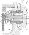
一部の実施形態では、タクタイルスイッチ自体が、電気接点を含む場合があり、シアプレートは、省略するか、又はタクタイルスイッチと一体化させることができる。図5〜図7は、ウェアラブル電子デバイスから取り外された、タクタイルスイッチの別の実施例の様々な図を示す。これらの実施形態では、タクタイルスイッチアセンブリは、1つ以上の入力のタイプを受信するとともに、デバイス内部の1つ以上の要素との電気連通を維持するように構成することができる。図5〜図7のタクタイルスイッチ314は、タクタイルスイッチ114と実質的に同じものとすることができるが、ドームの外側表面上の電気接点と一体に形成することができる。図5〜図7を参照すると、この実施形態では、タクタイルスイッチ314は、基板366と、基板366の底部表面374から延在する、1つ以上の支持部368とを含み得る。支持部368は、基板166上などの、ウェアラブル電子デバイス100内部で、タクタイルスイッチ314を支持する。(Brush contacts)
In some embodiments, the tactile switch itself may include the electrical contacts, and the shear plate may be omitted or integrated with the tactile switch. FIGS. 5-7 show various views of another embodiment of a tactile switch removed from the wearable electronic device. In these embodiments, the tactile switch assembly can be configured to receive one or more input types and maintain electrical communication with one or more elements inside the device.
タクタイルスイッチ314は、基板366の上部表面372から延在する、突起316を含み得る。突起316は、以下でより詳細に論じられる、ドーム352に関する電気接点を形成する。突起316は、処理要素124(図2を参照)と通信することが可能な、接続端子360a、360b、360d、360eのうちの1つ以上と、電気連通することができる。突起316は、導電性の突出部とすることができ、対応するドーム接点と選択的に連通するように構成された、導体パッド又は他の導電性セグメントを含み得る。
図5を参照すると、ドーム352は、弾性とすることができ、既定のユーザの力の下で陥没し、その初期の位置に跳ね戻るように構成することができる。ドーム352は、ドーム352の一方の側から延在する、脚部370を含み得る。脚部370は、限定するものではないが、フレキシブル回路(コード)、配線などの、1つ以上の電気連通機構を支持することができる。ドーム352はまた、ベース接点316の上に位置決めされる、ドーム空洞部320も画定することができる。ドーム352の上部表面322は、このドームが、ドームの上部表面322に十分な力が適用される場合にのみ、接点316に接触することができるように、突起316の上部表面から、空間的に隔てられるように構成することができる。ドーム接点318は、ドーム352の内部表面に、動作可能に接続することができ、少なくとも部分的に、突起316と位置合わせすることができる。 Referring to FIG. 5, the
ドーム352は、プラスチックなどの、非導電性材料とすることができる。一実施形態では、ドーム352は、射出成形プラスチックとすることができる。しかしながら、上述のように、ドーム352の1つ以上の構成要素は、フレキシブル回路(コード)、銅配線などの、導電性構成要素を含み得る。あるいは、ドーム352は、金属要素、又は導電性である他の材料とすることができ、ドーム352に接続された1つ以上の絶縁要素を含み得る。
図5及び図6を参照すると、タクタイルスイッチ314は、電気接点358を更に含み得るものであり、この電気接点358が、シアプレート156の接点158に置き換わり得ることにより、シアプレートを省略することができる。電気接点358は、ドーム352の上部表面322に、動作可能に接続することができる。タクタイルスイッチを使用して、回転入力を受け取ることが可能な実施形態では、電気接点358は、結合部318に関するブラシ接点を形成することにより、タクタイルスイッチ314と結合部318とを電気的に接続することができる。この方式で、この電気接点は、電気接点158と実質的に同様のものとすることができるが、しかしながら、この実施形態では、電気接点358は、ドーム352と一体に形成することができる。しかしながら、回転入力が所望されない実施形態では、電気接点358は、剪断力を受け取らない導電性表面とすることができる。 Referring to FIGS. 5 and 6, the
電気接点358は、接続端子360a、360b、360c、360dのうちの1つと通信する。例えば、電気接点358は、導線360aと通信することができる。一部の実施形態では、このドームは、導線360aに電気接点358を結合する、コード又は他のシアプレート含み得るものであり、又は代替的に、ドーム352自体が導電性である場合があり、それらの2つの構成要素を一体に結合する役割を果たし得る。
図3に示すように、電気接点158は、結合部218内に受容することができる。しかしながら、図6に示される実施形態などの、一部の実施形態では、電気接点358は、環状壁382によって取り囲まれる、受容空洞部384を画定することができる。これらの実施形態では、この電気接点内部に画定された陥凹部又は開口内に、結合部318の1つ以上の部分を受容することができる。この方式で、結合部218は、環状壁382の内部壁に接触して、電気接点358内部で回転することができる。 As shown in FIG. 3,
ここでタクタイルスイッチアセンブリの動作を、より詳細に論じる。図3及び図8を参照すると、例えば、ユーザ入力の力Fにより、結合部218が圧迫されると、結合部218は、電気接点358を圧迫する。電気接点358が圧迫されると、その力はドーム352に伝達され、ドーム352が陥没して、突起316の上部表面上に、ドーム接点318を押圧する。ドーム接点318が突起316に接触すると、電気信号が生成され、端子360a、360b、360c、360dのうちの1つを介して、処理要素124(図2を参照)に送信される。次いで、処理要素124は、タクタイルスイッチ314に対する、そのユーザ入力を登録する。 The operation of the tactile switch assembly will now be discussed in more detail. Referring to FIGS. 3 and 8, when the
図9は、ユーザが回転力を適用する際の、タクタイルスイッチ及び結合部の簡略前方立面図である。図9を参照すると、タクタイルスイッチアセンブリ310に、ユーザが回転入力の力Rを提供することが可能な実例では、結合部218は、ボタン148に適用された力を受け取ることにより、それに対応して結合部218を回転させることができる。結合部218が、電気接点358の陥凹部384(図6を参照)内に受容される実施形態では、結合部218は、環状壁382内部で回転し、電気接点358の、それらの壁及び/又は底部表面383(図6を参照)との接続を維持することができる。このことにより、結合部218は、ユーザからの回転入力と共に回転する一方で、依然として、タクタイルスイッチ314に対する電気的接続を維持することが可能となる。 FIG. 9 is a simplified front elevational view of the tactile switch and the coupling when the user applies a rotational force. Referring to FIG. 9, in an example where a user can provide a rotational input force R to the tactile switch assembly 310, the
(導電性突起)
一部の実施形態では、タクタイルスイッチの突起を導電性とすることができ、シアプレートを省略することができる。例えば、一部の実施形態では、ユーザ入力表面は、筐体に対して水平方向又は垂直方向に移動するなどの、平行移動するように構成することができ、これらの実施形態では、タクタイルスイッチは、剪断力を受け取ることができない。あるいは、タクタイルスイッチの突起は、剪断力を受け取る一方で、依然としてタクタイルスイッチをアクティブ化させるように構成することもできる。(Conductive protrusions)
In some embodiments, the protrusions of the tactile switch can be conductive and the shear plate can be omitted. For example, in some embodiments, the user input surface can be configured to translate, such as move horizontally or vertically relative to the housing, and in these embodiments the tactile switch is , Cannot receive shearing force. Alternatively, the protrusions of the tactile switch can be configured to receive the shear force while still activating the tactile switch.
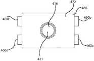
図10〜図12は、タクタイルスイッチの別の実施例の様々な図を示す。図10〜図12を参照すると、この実施形態でのタクタイルスイッチ414は、タクタイルスイッチ114、314と実質的に同様のものとすることができるが、導電性の突起を含み得る。換言すれば、シアプレートは、タクタイルスイッチの突起と一体化させることができる。具体的には、タクタイルスイッチ414は、基板466、1つ以上の基板支持部468、複数の接続端子460a、460b、460c、460d、及び突起416を含み得る。 10-12 show various views of another embodiment of a tactile switch. Referring to FIGS. 10-12, the
図10及び図11を参照すると、突起416は、基板466の上部表面472に、動作可能に接続することができる。一部の実施形態では、基板466、又は上部表面472の少なくとも諸部分を絶縁することにより、スイッチ414の特定の構成要素に関して、スイッチ414の様々な端子、並びに突起416を、電気的に絶縁することができる。突起416は、突起416の上部表面上のパッド421などの、導電性部分を含み得るものであり、又は、突起416は、導電性材料、若しくは導電性材料を混入した別の材料で、作製することができる。端子のうちの1つ以上は、突起416と電気連通する。例えば、端子460dは、突起416と通信することができ、その一方で、端子460a、460b、460cは、基板466内部のスイッチ接点に関する、1つ以上の接点として使用することができる。これらの実施形態では、突起416は、結合部が回転することを可能にする、ブラシ接点としての役割を果たし得る。 With reference to FIGS. 10 and 11, the
タクタイルスイッチ414は、図3のタクタイルスイッチアセンブリ110と共に使用することができる。これらの実施形態では、突起416は、結合部218の陥凹部224内に受容することができる。電気接点158と同様に、突起416は、環状壁226の側壁間に受容することができ、このことにより、突起及び結合部218が、動作可能に接続される。
タクタイルスイッチアセンブリ110が、図10〜図12のタクタイルスイッチ414を含む実施形態では、突起416は、導電性であるばかりではなく、剪断力及び過負荷に抵抗することもできるように、構成することができる。例えば、シアプレートが省略されているため、突起416は、結合部218が突起416の上部及び突起416の周りで回転する際に、剪断力を経験し得る。更には、この突起は、結合部218の力などの、機械的入力を受け取るように構成され、その力の負荷の下で、突起416は、端子のうちの1つ以上を一体に接続することによって、スイッチ回路を完成させる。一実施例として、突起416は、ボタン148に圧縮力が適用されると、少なくとも部分的に圧縮することにより、突起416は、ドームとして機能することが可能となり、ユーザに対する触覚フィードバックを提供するとともに、そのユーザの入力に対応する信号を生成することができる。 In embodiments where the
(結論)
上述の説明は、幅広い適用性を有する。例えば、本明細書で開示される実施例は、ウェアラブル電子デバイスに焦点を当てることができるが、本明細書で開示される概念は、実質的に任意の他のタイプの電子デバイスにも、等しく適用することができる点を理解されたい。同様に、入力ボタンは、腕時計用の竜頭に関連して論じることができるが、本明細書で開示されるデバイス及び技術は、他のタイプの入力ボタン構造体にも、等しく適用可能である。したがって、いずれの実施形態についての論考も、例示であることのみが意図され、特許請求の範囲を含む本開示の範囲を、これらの実施例に限定するように示唆することを意図するものではない。(Conclusion)
The above description has wide applicability. For example, while the embodiments disclosed herein may focus on wearable electronic devices, the concepts disclosed herein are equally applicable to virtually any other type of electronic device. It should be understood that it can be applied. Similarly, input buttons may be discussed in connection with a crown for a watch, but the devices and techniques disclosed herein are equally applicable to other types of input button structures. Accordingly, discussion of any embodiment is intended to be illustrative only, and not intended to imply that the scope of the disclosure, including the claims, is limited to these examples. .
Claims (19)
Translated fromJapanese内部容積を画定するエンクロージャと、前記内部容積内へ延長する開口と、
スイッチアセンブリであって、
並進入力及び回転入力を受け取るように構成されたボタンと、
前記ボタンに接続され、前記腕時計の前記開口内へ延長するシャフトと、
前記内部容積内に位置し、前記並進入力を検出するように構成された第1のセンサと、
前記内部容積内に位置し、前記シャフトから反射された光を検出することによって、前記回転入力を検出するように構成された光センサと、を含むスイッチアセンブリと、
タッチ入力を受け取り、前記腕時計のグラフィカル出力を描くように構成されたタッチ感知ディスプレイと、を備え、
前記グラフィカル出力は、前記ボタンによって受け取った前記並進入力、前記ボタンによって受け取った前記回転入力、及び前記タッチ感知ディスプレイによって受け取った前記タッチ入力のそれぞれに対して反応する、腕時計。A wristwatch,
An enclosure defining an interior volume; an opening extending into the interior volume;
A switch assembly,
A button configured to receive translational and rotational inputs;
A shaft connected to the button and extending into the opening of the watch;
A first sensor located within the interior volume and configured to detect the translation input;
Positioned within the interior volume,by detecting light reflected from said shaft, and a switch assemblycomprising, anoptical sensor configured to detect the rotational input,
A touch-sensitive display configured to receive a touch input and to render a graphical output of the watch.
The graphical output, the translation input, said rotary input, and react to each of the touch inputreceived by the touch-sensitive displayreceived by said buttonreceived by said button, watch.
前記アイコンの位置は、前記タッチ入力、前記並進入力、又は前記回転入力のうちの1つ以上に反応して変化可能である、請求項2に記載の腕時計。The icons of the icon group correspond to the received message,
3. The wristwatch according to claim 2, wherein the position of the icon is changeable in response to one or more of the touch input, the translation input, or the rotation input.
前記光センサは、前記シャフトの側部に沿って位置し、前記回転入力による前記シャフトの回転運動を検出するように構成される、請求項1に記載の腕時計。The first sensor is located near an end of the shaft and is configured to detect translational movement of the shaft due to the translational input;
The wristwatch of claim 1, wherein theoptical sensor is located along a side of the shaft and configured to detect rotational movement of the shaft due to the rotational input.
内部容積及び開口を画定する側壁を有するエンクロージャと、
前記内部容積内に少なくとも部分的に位置し、グラフィカル出力を描くように構成されたタッチ感知ディスプレイと、
前記開口を通って延長するシャフトを有するスイッチアセンブリと、
前記内部容積内で前記シャフトの端部の近くに位置し、前記シャフトの並進運動を検出するように構成された第1のセンサと、
前記内部容積内で前記シャフトの側部に沿って位置し、前記シャフトの回転運動に起因する反射光の変化を検出することによって、前記シャフトの回転運動を検出するように構成された光センサと、を備え、
前記グラフィカル出力は、検出された前記並進運動及び前記回転運動をそれぞれに反応して変化するように構成されている、腕時計。A wristwatch,
An enclosure having sidewalls defining an interior volume and an opening;
A touch-sensitive display located at least partially within the interior volume and configured to draw a graphical output;
A switch assembly having a shaft extending through the opening;
A first sensor located within the interior volume near an end of the shaft and configured to detect translational movement of the shaft;
Located along the sides of the shaft within the interior volume,by detecting changes in reflected light caused by the rotational movement of the shaft, andan optical sensor configured to detect rotational movement of the shaft ,
A wristwatch, wherein the graphical output is configured to change in response to the detected translational and rotational movements, respectively.
前記処理要素は、
前記シャフトの検出された前記並進運動を使用して前記腕時計の第1の機能を制御し、
前記シャフトの検出された前記回転運動を使用して前記腕時計の第2の機能を制御する、請求項8に記載の腕時計。Further comprising a processing element,
The processing element comprises:
Controlling a first function of the watch using the detected translation of the shaft;
9. The wristwatch according to claim 8, wherein the detected rotational movement of the shaft is used to control a second function of the wristwatch.
前記ボタンは、前記シャフトの前記並進運動を生じさせる内側への並進入力を受け取るように構成されている、請求項8に記載の腕時計。The switch assembly further includes a button connected to the shaft and located along an exterior of the enclosure;
The wristwatch of claim 8, wherein the button is configured to receive an inward translation input that causes the translation of the shaft.
前記ボタンの並進入力は、前記シャフトが前記ドームスイッチ内へ突っ込むようにさせて、それにより、前記ドームスイッチを陥没させ、
前記ドームスイッチは、前記ドームスイッチが陥没したときにタクタイルレスポンスを生成するように構成されている、請求項12に記載の腕時計。The first sensor is a dome switch;
The translational input of the button causes the shaft to plunge into the dome switch, thereby causing the dome switch to collapse,
13. The wristwatch of claim 12, wherein the dome switch is configured to generate a tactile response when the dome switch collapses.
前記光センサは、前記パターン付けされた表面の運動を追跡するように構成されている、請求項12に記載の腕時計。Before Symbol shaft includes a patterned surface,
The wristwatch of claim 12, wherein the light sensor is configured to track movement of the patterned surface.
内部容積、第1の開口及び第2の開口を画定するエンクロージャと、
回転入力及び並進入力を受け取るように構成されたスイッチアセンブリであって、
前記第2の開口を通って前記内部容積内へ延長するシャフトと、
前記シャフトに接続されたボタンと、
前記内部容積内で前記シャフトの軸に沿って位置する第1のセンサと、
前記内部容積内で前記シャフトの前記軸からオフセットして位置する第2のセンサと、を含むスイッチアセンブリと、
少なくとも部分的に前記第1の開口内に位置し、タッチ入力を受け取り、グラフィカル出力を生成するように構成されたタッチ感知ディスプレイと、を備え、
前記グラフィカル出力は、前記並進入力に反応して第1の手段で修正されるように構成され、
前記グラフィカル出力は、前記回転入力に反応して第2の手段で修正されるように構成され、
前記グラフィカル出力は、前記タッチ入力に反応して第3の手段で修正されるように構成されている、腕時計。A wristwatch,
An enclosure defining an interior volume, a first opening and a second opening ;
A switch assembly configured to receive a rotation input and a translation input,
A shaft extendingthrough the second opening into the interior volume;
A button connected to the shaft;
A first sensor located along the axis of the shaft within the interior volume;
A second sensor positioned within the interior volume and offset from the axis of the shaft; and
A touch-sensitive displaypositioned at least partially within the first opening , configured to receive a touch input and generate a graphical output.
The graphical output is configured to be modified by first means in response to the translation input;
The graphical output is configured to be modified by second means in response to the rotation input;
The wristwatch, wherein the graphical output is configured to be modified by third means in response to the touch input.
前記並進入力は、 前記シャフトを内側へ前記タクタイルドームに向けて突っ込み、
前記タクタイルドームが陥没したときに、前記第1のセンサの出力が生じる、請求項15に記載の腕時計。The first sensor includes a tactile dome;
The translational input rushes the shaft inward toward the tactile dome,
Wherein when the tactile dome is depressed, the output of the first sensor occurs, according to claim 15 watches.
Applications Claiming Priority (2)
| Application Number | Priority Date | Filing Date | Title |
|---|---|---|---|
| US201361864389P | 2013-08-09 | 2013-08-09 | |
| US61/864,389 | 2013-08-09 |
Related Parent Applications (1)
| Application Number | Title | Priority Date | Filing Date |
|---|---|---|---|
| JP2016533470ADivisionJP6345782B2 (en) | 2013-08-09 | 2014-08-08 | Tactile switches for electronic devices |
Related Child Applications (1)
| Application Number | Title | Priority Date | Filing Date |
|---|---|---|---|
| JP2019007498ADivisionJP6816178B2 (en) | 2013-08-09 | 2019-01-21 | Tactile switch for electronic devices |
Publications (2)
| Publication Number | Publication Date |
|---|---|
| JP2018133343A JP2018133343A (en) | 2018-08-23 |
| JP6648192B2true JP6648192B2 (en) | 2020-02-14 |
Family
ID=51483661
Family Applications (6)
| Application Number | Title | Priority Date | Filing Date |
|---|---|---|---|
| JP2016533470AActiveJP6345782B2 (en) | 2013-08-09 | 2014-08-08 | Tactile switches for electronic devices |
| JP2018098487AActiveJP6648192B2 (en) | 2013-08-09 | 2018-05-23 | Tactile switches for electronic devices |
| JP2019007498AActiveJP6816178B2 (en) | 2013-08-09 | 2019-01-21 | Tactile switch for electronic devices |
| JP2020213480AActiveJP7091433B2 (en) | 2013-08-09 | 2020-12-23 | Tactile switch for electronic devices |
| JP2022096568AActiveJP7579826B2 (en) | 2013-08-09 | 2022-06-15 | Tactile Switches for Electronic Devices |
| JP2024188914APendingJP2025028786A (en) | 2013-08-09 | 2024-10-28 | Tactile Switches for Electronic Devices |
Family Applications Before (1)
| Application Number | Title | Priority Date | Filing Date |
|---|---|---|---|
| JP2016533470AActiveJP6345782B2 (en) | 2013-08-09 | 2014-08-08 | Tactile switches for electronic devices |
Family Applications After (4)
| Application Number | Title | Priority Date | Filing Date |
|---|---|---|---|
| JP2019007498AActiveJP6816178B2 (en) | 2013-08-09 | 2019-01-21 | Tactile switch for electronic devices |
| JP2020213480AActiveJP7091433B2 (en) | 2013-08-09 | 2020-12-23 | Tactile switch for electronic devices |
| JP2022096568AActiveJP7579826B2 (en) | 2013-08-09 | 2022-06-15 | Tactile Switches for Electronic Devices |
| JP2024188914APendingJP2025028786A (en) | 2013-08-09 | 2024-10-28 | Tactile Switches for Electronic Devices |
Country Status (7)
| Country | Link |
|---|---|
| US (14) | US9627163B2 (en) |
| EP (2) | EP3014400B1 (en) |
| JP (6) | JP6345782B2 (en) |
| KR (7) | KR102430508B1 (en) |
| CN (4) | CN109634447B (en) |
| AU (1) | AU2014305787B2 (en) |
| WO (1) | WO2015021391A1 (en) |
Families Citing this family (127)
| Publication number | Priority date | Publication date | Assignee | Title |
|---|---|---|---|---|
| US9100493B1 (en)* | 2011-07-18 | 2015-08-04 | Andrew H B Zhou | Wearable personal digital device for facilitating mobile device payments and personal use |
| US11513675B2 (en)* | 2012-12-29 | 2022-11-29 | Apple Inc. | User interface for manipulating user interface objects |
| US10055030B2 (en) | 2013-05-17 | 2018-08-21 | Apple Inc. | Dynamic visual indications for input devices |
| US9753436B2 (en) | 2013-06-11 | 2017-09-05 | Apple Inc. | Rotary input mechanism for an electronic device |
| EP3014400B1 (en) | 2013-08-09 | 2020-06-03 | Apple Inc. | Tactile switch for an electronic device |
| CN110795005A (en) | 2013-09-03 | 2020-02-14 | 苹果公司 | User interface for manipulating user interface objects using magnetic properties |
| US12287962B2 (en) | 2013-09-03 | 2025-04-29 | Apple Inc. | User interface for manipulating user interface objects |
| US10503388B2 (en) | 2013-09-03 | 2019-12-10 | Apple Inc. | Crown input for a wearable electronic device |
| US11068128B2 (en) | 2013-09-03 | 2021-07-20 | Apple Inc. | User interface object manipulations in a user interface |
| US10545657B2 (en) | 2013-09-03 | 2020-01-28 | Apple Inc. | User interface for manipulating user interface objects |
| WO2015088492A1 (en) | 2013-12-10 | 2015-06-18 | Apple Inc. | Input friction mechanism for rotary inputs of electronic devices |
| CN105979855B (en) | 2014-02-11 | 2019-05-28 | 苹果公司 | Detect limbs wearing wearable electronics |
| US10827268B2 (en) | 2014-02-11 | 2020-11-03 | Apple Inc. | Detecting an installation position of a wearable electronic device |
| US10048802B2 (en) | 2014-02-12 | 2018-08-14 | Apple Inc. | Rejection of false turns of rotary inputs for electronic devices |
| KR101601393B1 (en)* | 2014-02-20 | 2016-03-09 | 현대자동차주식회사 | Emergency button for vehicle |
| EP3147747A1 (en) | 2014-06-27 | 2017-03-29 | Apple Inc. | Manipulation of calendar application in device with touch screen |
| US10190891B1 (en) | 2014-07-16 | 2019-01-29 | Apple Inc. | Optical encoder for detecting rotational and axial movement |
| CN106662966B (en) | 2014-09-02 | 2020-08-18 | 苹果公司 | Multi-dimensional object rearrangement |
| US20160062571A1 (en) | 2014-09-02 | 2016-03-03 | Apple Inc. | Reduced size user interface |
| CN106797493A (en) | 2014-09-02 | 2017-05-31 | 苹果公司 | Music user interface |
| KR20250021617A (en) | 2014-09-02 | 2025-02-13 | 애플 인크. | Wearable electronic device |
| TWI582641B (en) | 2014-09-02 | 2017-05-11 | 蘋果公司 | Button functionality |
| TWI676127B (en) | 2014-09-02 | 2019-11-01 | 美商蘋果公司 | Method, system, electronic device and computer-readable storage medium regarding electronic mail user interface |
| US9723997B1 (en) | 2014-09-26 | 2017-08-08 | Apple Inc. | Electronic device that computes health data |
| US10730687B2 (en)* | 2014-10-16 | 2020-08-04 | RxCap Inc. | Intelligent medicine dispenser |
| US10365807B2 (en) | 2015-03-02 | 2019-07-30 | Apple Inc. | Control of system zoom magnification using a rotatable input mechanism |
| WO2016141228A1 (en) | 2015-03-05 | 2016-09-09 | Apple Inc. | Optical encoder with direction-dependent optical properties |
| US9651405B1 (en) | 2015-03-06 | 2017-05-16 | Apple Inc. | Dynamic adjustment of a sampling rate for an optical encoder |
| EP3251139B1 (en)* | 2015-03-08 | 2021-04-28 | Apple Inc. | Compressible seal for rotatable and translatable input mechanisms |
| US10018966B2 (en) | 2015-04-24 | 2018-07-10 | Apple Inc. | Cover member for an input mechanism of an electronic device |
| JP6587867B2 (en)* | 2015-08-27 | 2019-10-09 | 文化シヤッター株式会社 | Switchgear operating method, program, recording medium, wearable computer, and switchgear operating system |
| US10444040B2 (en)* | 2015-09-25 | 2019-10-15 | Apple Inc. | Crown with three-dimensional input |
| US9646471B2 (en)* | 2015-09-30 | 2017-05-09 | Apple Inc. | User interface using tactile output |
| US10503271B2 (en) | 2015-09-30 | 2019-12-10 | Apple Inc. | Proximity detection for an input mechanism of an electronic device |
| KR102459243B1 (en)* | 2015-10-08 | 2022-10-26 | 삼성전자 주식회사 | Electronic device and method for photographing thereof |
| US11429199B2 (en)* | 2015-12-14 | 2022-08-30 | Pixart Imaging Inc. | Optical sensor apparatus and method capable of accurately determining motion/rotation of object having long shape and/or flexible form |
| TWI585371B (en)* | 2015-12-14 | 2017-06-01 | 原相科技股份有限公司 | Electronic apparatus |
| CN106896939B (en)* | 2015-12-21 | 2019-10-18 | 原相科技股份有限公司 | electronic device |
| US9891651B2 (en) | 2016-02-27 | 2018-02-13 | Apple Inc. | Rotatable input mechanism having adjustable output |
| WO2017152139A1 (en)* | 2016-03-04 | 2017-09-08 | Apple Inc. | Input with haptic feedback |
| US9818272B2 (en)* | 2016-04-04 | 2017-11-14 | Apple Inc. | Electronic device including sound level based driving of haptic actuator and related methods |
| EP3242307B1 (en)* | 2016-05-03 | 2020-10-28 | Electrolux Appliances Aktiebolag | Switching element for a control device |
| US10585480B1 (en) | 2016-05-10 | 2020-03-10 | Apple Inc. | Electronic device with an input device having a haptic engine |
| US10551798B1 (en) | 2016-05-17 | 2020-02-04 | Apple Inc. | Rotatable crown for an electronic device |
| DK201670595A1 (en) | 2016-06-11 | 2018-01-22 | Apple Inc | Configuring context-specific user interfaces |
| DK201670580A1 (en) | 2016-06-12 | 2018-01-02 | Apple Inc | Wrist-based tactile time feedback for non-sighted users |
| US10691166B2 (en) | 2016-07-04 | 2020-06-23 | Huawei Technologies Co., Ltd. | Wearable electronic device having multiple touch sensitive areas outside of viewable display area |
| US10061399B2 (en) | 2016-07-15 | 2018-08-28 | Apple Inc. | Capacitive gap sensor ring for an input device |
| US10019097B2 (en) | 2016-07-25 | 2018-07-10 | Apple Inc. | Force-detecting input structure |
| CN106098453A (en)* | 2016-08-04 | 2016-11-09 | 青岛歌尔声学科技有限公司 | There is the electronic product of button |
| US11782531B2 (en)* | 2016-09-19 | 2023-10-10 | Apple Inc. | Gesture detection, list navigation, and item selection using a crown and sensors |
| US10901539B2 (en)* | 2017-02-15 | 2021-01-26 | Hewlett-Packard Development Company, L.P. | Input modules associated with multiple input interfaces |
| US10866619B1 (en) | 2017-06-19 | 2020-12-15 | Apple Inc. | Electronic device having sealed button biometric sensing system |
| US10664074B2 (en) | 2017-06-19 | 2020-05-26 | Apple Inc. | Contact-sensitive crown for an electronic watch |
| US10962935B1 (en) | 2017-07-18 | 2021-03-30 | Apple Inc. | Tri-axis force sensor |
| CN109273305B (en)* | 2017-07-18 | 2020-12-08 | 深圳富泰宏精密工业有限公司 | Button and electronic device having the same |
| US10831299B1 (en)* | 2017-08-16 | 2020-11-10 | Apple Inc. | Force-sensing button for electronic devices |
| US11109797B2 (en) | 2017-09-05 | 2021-09-07 | Apple Inc. | Portable electronic device having an integrated bio-sensor |
| EP4252632A3 (en)* | 2017-09-05 | 2024-05-01 | Apple Inc. | Wearable electronic device with electrodes for sensing biological parameters |
| CN115177223B (en) | 2017-09-05 | 2025-09-30 | 苹果公司 | Portable electronic devices with integrated biosensors |
| US10381881B2 (en)* | 2017-09-06 | 2019-08-13 | Apple Inc. | Architecture of portable electronic devices with wireless charging receiver systems |
| US10855110B2 (en) | 2017-09-06 | 2020-12-01 | Apple Inc. | Antenna integration for portable electronic devices having wireless charging receiver systems |
| US11054932B2 (en) | 2017-09-06 | 2021-07-06 | Apple Inc. | Electronic device having a touch sensor, force sensor, and haptic actuator in an integrated module |
| US10852697B2 (en) | 2017-09-11 | 2020-12-01 | Apple Inc. | Crown assembly for watches |
| US10203662B1 (en) | 2017-09-25 | 2019-02-12 | Apple Inc. | Optical position sensor for a crown |
| EP3459447B1 (en) | 2017-09-26 | 2024-10-16 | Apple Inc. | Optical sensor subsystem adjacent a cover of an electronic device housing |
| US10474108B2 (en) | 2017-09-27 | 2019-11-12 | Apple Inc. | Magnetic sensor array for crown rotation |
| CN107887211B (en)* | 2017-12-29 | 2021-03-23 | 歌尔科技有限公司 | Key and electronic equipment |
| CH714827A2 (en)* | 2018-03-21 | 2019-09-30 | Icoflex Sarl | Bracelet and / or movement object comprising a photovoltaic cell. |
| TWI713069B (en)* | 2018-05-22 | 2020-12-11 | 仁寶電腦工業股份有限公司 | Electronic device |
| CN110520823A (en) | 2018-06-06 | 2019-11-29 | 高驰运动科技(深圳)有限公司 | A kind of smartwatch exchange method, smartwatch and photoelectricity knob assembly |
| US11360440B2 (en) | 2018-06-25 | 2022-06-14 | Apple Inc. | Crown for an electronic watch |
| US11209783B2 (en)* | 2018-07-30 | 2021-12-28 | Apple Inc. | Watch with optical sensor for user input |
| US11561515B2 (en) | 2018-08-02 | 2023-01-24 | Apple Inc. | Crown for an electronic watch |
| CN211293787U (en) | 2018-08-24 | 2020-08-18 | 苹果公司 | Electronic watch |
| US12259690B2 (en)* | 2018-08-24 | 2025-03-25 | Apple Inc. | Watch crown having a conductive surface |
| US11181863B2 (en) | 2018-08-24 | 2021-11-23 | Apple Inc. | Conductive cap for watch crown |
| CN209625187U (en) | 2018-08-30 | 2019-11-12 | 苹果公司 | Electronic Watches and Electronic Devices |
| US10936071B2 (en)* | 2018-08-30 | 2021-03-02 | Apple Inc. | Wearable electronic device with haptic rotatable input |
| US11194298B2 (en) | 2018-08-30 | 2021-12-07 | Apple Inc. | Crown assembly for an electronic watch |
| US11435830B2 (en) | 2018-09-11 | 2022-09-06 | Apple Inc. | Content-based tactile outputs |
| CN110096157B (en)* | 2018-09-11 | 2021-05-11 | 苹果公司 | Content-based haptic output |
| US10712824B2 (en) | 2018-09-11 | 2020-07-14 | Apple Inc. | Content-based tactile outputs |
| US10966007B1 (en) | 2018-09-25 | 2021-03-30 | Apple Inc. | Haptic output system |
| US11194299B1 (en) | 2019-02-12 | 2021-12-07 | Apple Inc. | Variable frictional feedback device for a digital crown of an electronic watch |
| CN109782570A (en)* | 2019-02-27 | 2019-05-21 | 广东乐芯智能科技有限公司 | A kind of regulating system and method for smartwatch pointer |
| WO2020211336A1 (en)* | 2019-04-19 | 2020-10-22 | 广东小天才科技有限公司 | Smart host having multifunctional crown, smart watch, and control method |
| TWI689809B (en) | 2019-05-01 | 2020-04-01 | 和碩聯合科技股份有限公司 | Trigger device and handheld pistol grip using thereof |
| WO2020235221A1 (en)* | 2019-05-20 | 2020-11-26 | シチズン時計株式会社 | Timepiece |
| US10996761B2 (en) | 2019-06-01 | 2021-05-04 | Apple Inc. | User interfaces for non-visual output of time |
| KR102861687B1 (en)* | 2019-07-02 | 2025-09-18 | 삼성전자주식회사 | Electronic device including electrically connecting member |
| CN110189952B (en)* | 2019-07-02 | 2024-07-09 | 青岛易来智能科技股份有限公司 | Rotary key switch |
| CN211294932U (en) | 2019-11-26 | 2020-08-18 | Oppo广东移动通信有限公司 | Elastic parts, electronic devices and wearable devices |
| EP3835892B1 (en) | 2019-12-10 | 2022-08-10 | The Swatch Group Research and Development Ltd | Watch provided with a controller |
| EP3869278B1 (en)* | 2020-02-21 | 2023-03-08 | Montres Breguet S.A. | Vertical clutch device for a timepiece |
| CN111338203B (en)* | 2020-02-27 | 2021-07-23 | 维沃移动通信有限公司 | An electronic device and control method |
| EP3893063B1 (en)* | 2020-04-06 | 2022-08-17 | ETA SA Manufacture Horlogère Suisse | Device for controlling functions of a watch |
| US11556095B2 (en)* | 2020-04-15 | 2023-01-17 | Apple Inc. | Modular sensing assembly for an electronic device |
| US11550268B2 (en) | 2020-06-02 | 2023-01-10 | Apple Inc. | Switch module for electronic crown assembly |
| US11983035B2 (en) | 2020-06-11 | 2024-05-14 | Apple Inc. | Electronic device |
| US11024135B1 (en) | 2020-06-17 | 2021-06-01 | Apple Inc. | Portable electronic device having a haptic button assembly |
| CN111657929B (en)* | 2020-07-21 | 2023-08-25 | 广东高驰运动科技股份有限公司 | Wearable device and method of use |
| KR20220016718A (en)* | 2020-08-03 | 2022-02-10 | 삼성전자주식회사 | Electronic device including electrode button |
| CN114125091B (en)* | 2020-08-31 | 2023-10-27 | 深圳市万普拉斯科技有限公司 | An input structure and electronic device |
| US11457300B2 (en) | 2020-09-16 | 2022-09-27 | Apple Inc. | Support structure for earpiece cushion |
| US11272279B1 (en) | 2020-09-16 | 2022-03-08 | Apple Inc. | Headphones with off-center pivoting earpiece |
| US11272280B1 (en) | 2020-09-16 | 2022-03-08 | Apple Inc. | Earpiece with cushion retention |
| US11109135B1 (en) | 2020-09-16 | 2021-08-31 | Apple Inc. | Headphones with rotatable user input mechanism |
| US11190878B1 (en) | 2020-09-16 | 2021-11-30 | Apple Inc. | Headphones with on-head detection |
| US11184696B1 (en) | 2020-09-16 | 2021-11-23 | Apple Inc. | Wireless headphones with slot antenna |
| EP3971932B1 (en)* | 2020-09-16 | 2024-10-09 | Apple Inc. | Headphones with rotatable user input mechanism |
| CN112433460B (en)* | 2020-11-26 | 2022-03-01 | 歌尔科技有限公司 | Crown and wrist wearing equipment with same |
| CN112596365B (en)* | 2020-12-16 | 2022-07-22 | 歌尔光学科技有限公司 | A rotary crown and a smart watch |
| US11747919B1 (en)* | 2021-05-14 | 2023-09-05 | Apple Inc. | Multi-input for rotating and translating crown modules |
| US11893212B2 (en) | 2021-06-06 | 2024-02-06 | Apple Inc. | User interfaces for managing application widgets |
| US12092996B2 (en) | 2021-07-16 | 2024-09-17 | Apple Inc. | Laser-based rotation sensor for a crown of an electronic watch |
| US12396686B2 (en) | 2021-08-31 | 2025-08-26 | Apple Inc. | Sensing health parameters in wearable devices |
| CN114093702B (en)* | 2021-11-30 | 2024-04-26 | 华为技术有限公司 | Key structure and wearable equipment |
| CN114220688B (en)* | 2021-11-30 | 2024-04-09 | 华为技术有限公司 | Button structure and wearable devices |
| TWM633344U (en)* | 2022-01-04 | 2022-10-21 | 致伸科技股份有限公司 | Roller |
| FI4231100T3 (en)* | 2022-02-22 | 2024-11-29 | Eta Sa Mft Horlogere Suisse | CLOCK CONTROLLER |
| US12189347B2 (en) | 2022-06-14 | 2025-01-07 | Apple Inc. | Rotation sensor for a crown of an electronic watch |
| CN115227251B (en)* | 2022-07-29 | 2025-07-22 | 东莞华贝电子科技有限公司 | Wearable device |
| WO2024149857A1 (en)* | 2023-01-13 | 2024-07-18 | Nicoventures Trading Limited | Aerosol provision device button assembly |
| US20230421679A1 (en) | 2023-01-27 | 2023-12-28 | Apple Inc. | Handheld electronic device |
| FR3146588A1 (en) | 2023-03-17 | 2024-09-20 | Withings | ECG algorithm and embedding in an ECG analysis device |
| CN117038378A (en)* | 2023-08-15 | 2023-11-10 | 李文杰 | Multifunctional key module |
Family Cites Families (667)
| Publication number | Priority date | Publication date | Assignee | Title |
|---|---|---|---|---|
| CH188928A (en) | 1934-10-13 | 1937-01-31 | Kinkhorst Hendrik | Dustproof pocket or wrist watch. |
| US2288215A (en) | 1937-06-21 | 1942-06-30 | Taubert Marcel | Pusher device for chronographs |
| US2237860A (en) | 1937-12-09 | 1941-04-08 | Bolle Leon | Fluidtight closure for watchcases |
| US2497935A (en) | 1947-07-11 | 1950-02-21 | Feurer Bros Inc | Dust-tight watch crown |
| US2797592A (en) | 1952-09-03 | 1957-07-02 | Patent Button Company Of Tenne | Appliance knobs |
| US2788236A (en) | 1953-04-27 | 1957-04-09 | Independent Lock Co | Plural-part knob construction |
| US2771734A (en) | 1953-05-06 | 1956-11-27 | Morf Ernest | Watch crown seal |
| NL94688C (en) | 1958-05-02 | 1960-06-15 | ||
| US3040514A (en) | 1958-12-31 | 1962-06-26 | Dinstman Hyman | Waterproof stem seal for watch cases |
| US3056030A (en) | 1960-08-31 | 1962-09-25 | Burroughs Corp | Light responsive photo-optical keyboard |
| US3130539A (en) | 1962-02-01 | 1964-04-28 | Robert L Davis | Watch crown seal |
| US3355873A (en) | 1964-07-09 | 1967-12-05 | Morf Ernest | Watertight shaped watch |
| US3410247A (en) | 1965-03-30 | 1968-11-12 | Westinghouse Electric Corp | Control knob assembly |
| US3362154A (en) | 1966-03-16 | 1968-01-09 | Rolex Montres | Watertight control device, with pushbutton, for timepiece |
| CH480680A (en) | 1967-07-10 | 1969-12-15 | Omega Louis Brandt & Freres S | Waterproof watch box |
| CH897168A4 (en) | 1968-06-17 | 1972-05-15 | ||
| CH1885268A4 (en) | 1968-12-18 | 1971-02-15 | Omega Brandt & Freres Sa Louis | Waterproof control unit for watch |
| DE1927901A1 (en) | 1969-05-31 | 1970-12-03 | Sel Kontakt Bauelemente Gmbh | Knob |
| JPS5638917B1 (en) | 1971-06-23 | 1981-09-09 | ||
| DE2352016A1 (en) | 1973-10-17 | 1975-04-30 | Vdo Schindling | TRANSMISSION FOR SMALL PERFORMANCE |
| US3937002A (en) | 1974-08-20 | 1976-02-10 | Bulova Watch Company, Inc. | Solid state, battery operated electronic watch having arm-actuated battery switch |
| US4133404A (en) | 1975-04-25 | 1979-01-09 | Agile Systems, Inc. | Automatic lawn mower |
| US4007347A (en)* | 1975-07-28 | 1977-02-08 | Haber Terry M | Simplified actuating switch for electronic timepieces |
| US4037068A (en) | 1975-09-17 | 1977-07-19 | Gaynor Edwin S | Two-stage rocker switch for controlling a fluorescent lamp circuit |
| US4051665A (en) | 1976-01-14 | 1977-10-04 | Hayden/Arn Productions Limited | Operating switch and retainer for digital watch cases |
| US4031341A (en) | 1976-01-14 | 1977-06-21 | Timex Corporation | Dual function pusher and rotate switch for solid state digital watches having detent spring |
| JPS52151058A (en)* | 1976-06-11 | 1977-12-15 | Citizen Watch Co Ltd | Push button construction of electronic watches |
| US4077200A (en) | 1976-08-23 | 1978-03-07 | Fairchild Camera And Instrument Corporation | Case for an electronic wristwatch module |
| US4170104A (en)* | 1976-12-01 | 1979-10-09 | Citizen Watch Company Limited | Switch mechanism for wristwatch |
| JPS5393067A (en)* | 1977-01-26 | 1978-08-15 | Seiko Instr & Electronics Ltd | Heart beat meter of wristwatch |
| JPS53110553A (en) | 1977-03-08 | 1978-09-27 | Sony Corp | Measurement apparatus of gradients of curved faces |
| JPS5630557Y2 (en) | 1977-11-10 | 1981-07-21 | ||
| JPS5487779U (en)* | 1977-12-02 | 1979-06-21 | ||
| JPS5478178A (en)* | 1977-12-02 | 1979-06-22 | Seikosha Kk | Timepiece |
| JPS5487779A (en) | 1977-12-24 | 1979-07-12 | Fuji Chem Ind Co Ltd | Method of making dry type of friction parts |
| JPS594302Y2 (en) | 1978-04-19 | 1984-02-07 | セイコーエプソン株式会社 | Clock switching mechanism |
| DE2837939C2 (en) | 1978-08-31 | 1980-10-23 | Iwc International Watch Co. Ag, Schaffhausen | Watch case with push buttons |
| US4258096A (en) | 1978-11-09 | 1981-03-24 | Sheldahl, Inc. | Composite top membrane for flat panel switch arrays |
| US4311990A (en) | 1978-11-16 | 1982-01-19 | Optical Techniques International, Inc. | Photo-optical keyboards |
| JPS55155424A (en) | 1979-05-24 | 1980-12-03 | Omron Tateisi Electronics Co | Dip switch |
| US4287400A (en) | 1979-11-01 | 1981-09-01 | Timex Corporation | Water-resistant rocker switch |
| DE3004126C2 (en) | 1980-02-05 | 1986-06-05 | Schmid, geb.Bühl, Annemarie, 7914 Pfaffenhofen | Bioelectric skin contact electrode |
| CH632894B (en) | 1980-02-13 | Ebauches Electroniques Sa | DEVICE FOR THE SELECTION OR CORRECTION OF INFORMATION IN AN ELECTRONIC WATCH. | |
| JPS578582A (en) | 1980-06-19 | 1982-01-16 | Tokyo Shibaura Electric Co | Display control system |
| US4311026A (en) | 1980-07-10 | 1982-01-19 | Jewelmasters, Inc. | Composite finger ring and method of making same |
| JPS5734457A (en) | 1980-08-08 | 1982-02-24 | Nec Corp | Rotation measuring apparatus |
| US4345119A (en) | 1981-02-19 | 1982-08-17 | Motorola Inc. | Membrane switch assembly with improved spacer |
| US4396298A (en) | 1981-08-03 | 1983-08-02 | Textron, Inc. | Case for electronic watch module |
| US4395134A (en) | 1982-02-17 | 1983-07-26 | Luce Nunzio A | Joystick switch for timepieces |
| US4417824A (en) | 1982-03-29 | 1983-11-29 | International Business Machines Corporation | Optical keyboard with common light transmission members |
| US4520306A (en) | 1983-08-22 | 1985-05-28 | Lutron Electronics Co., Inc. | Wall mounted electrical voltage control switch |
| CH653848GA3 (en) | 1983-10-25 | 1986-01-31 | ||
| JPS60103937A (en)* | 1983-11-11 | 1985-06-08 | セイコーインスツルメンツ株式会社 | Wristwatch type electrocardiograph monitor apparatus |
| JPS60103936A (en)* | 1983-11-11 | 1985-06-08 | セイコーインスツルメンツ株式会社 | Heart potential recorder |
| US4641026A (en) | 1984-02-02 | 1987-02-03 | Texas Instruments Incorporated | Optically activated keyboard for digital system |
| US4617461A (en) | 1984-04-25 | 1986-10-14 | Burroughs Corporation | Fluorescent optical switch and keyboard apparatus |
| US4671671A (en) | 1984-06-18 | 1987-06-09 | Casio Computer Co., Ltd. | Small electronic apparatus with optical input device |
| US4581509A (en) | 1984-07-20 | 1986-04-08 | Texas Instruments Incorporated | Features of a condition responsive switch |
| US4670737A (en) | 1984-09-13 | 1987-06-02 | Sangamo Weston, Inc. | Method of initializing an optical encoder |
| US4634861A (en) | 1984-12-19 | 1987-01-06 | General Instrument Corporation | Rotary switch with reflector coded actuator drum |
| EP0195636B1 (en) | 1985-03-19 | 1991-07-10 | Citizen Watch Co. Ltd. | Wristwatch with pressure sensor |
| WO1987005172A1 (en) | 1986-02-24 | 1987-08-27 | Alain Souloumiac | Improvements to optical scanning keyboards |
| FR2597988A1 (en) | 1986-04-25 | 1987-10-30 | Souloumiac Alain | IMPROVING MATRIX SCANNING OPTICAL KEYBOARDS |
| JPS6326927U (en)* | 1986-08-04 | 1988-02-22 | ||
| DE3700856A1 (en) | 1987-01-14 | 1988-07-28 | Telefunken Electronic Gmbh | OPTOELECTRONIC KEYBOARD |
| DE3706194A1 (en)* | 1987-02-26 | 1988-09-15 | Fraunhofer Ges Forschung | SWITCHING DEVICE |
| JPH0650927Y2 (en)* | 1987-05-08 | 1994-12-21 | オムロン株式会社 | Detector |
| US4766642A (en) | 1987-08-31 | 1988-08-30 | Kohler Co. | Handle assembly |
| US4914831A (en) | 1988-03-04 | 1990-04-10 | Casio Computer Co., Ltd. | Rotation detecting apparatus |
| JP2709088B2 (en) | 1988-08-24 | 1998-02-04 | 株式会社リコー | Rotation amount measurement method |
| US4922070A (en) | 1988-12-16 | 1990-05-01 | Motorola, Inc. | Switch assembly |
| US4952799A (en) | 1989-03-10 | 1990-08-28 | Hewlett-Packard Company | Reflective shaft angle encoder |
| JPH02285214A (en) | 1989-04-26 | 1990-11-22 | Canon Inc | Length measuring device and scale member used therein |
| US5034602A (en) | 1989-07-21 | 1991-07-23 | Texas Instruments Incorporated | Optically activated keyboard for digital system having character back lighting |
| US5001687A (en) | 1990-01-02 | 1991-03-19 | Brien Andre | Wristwatch with a switching crown |
| JP3007660B2 (en) | 1990-08-08 | 2000-02-07 | 株式会社リコー | Absolute encoder |
| JP3034585B2 (en) | 1990-10-19 | 2000-04-17 | 株式会社リコー | Encoder using shadow picture pattern |
| US5177355A (en) | 1991-04-01 | 1993-01-05 | Motorola, Inc. | Rotary control switch with plural movable concave light reflectors |
| JPH04349316A (en) | 1991-05-24 | 1992-12-03 | Matsushita Electric Ind Co Ltd | Waterproof switch for electronic equipment |
| JPH0650927A (en) | 1991-07-12 | 1994-02-25 | Hino Motors Ltd | Detecting method for crack or fracture caused by stress corrosion cracking |
| US5471054A (en) | 1991-09-30 | 1995-11-28 | Nf. T&M. Systems, Inc. | Encoder for providing calibrated measurement capability of rotation or linear movement of an object, label medium and an optical identification system |
| US5214278A (en) | 1991-11-01 | 1993-05-25 | Combustion Engineering, Inc. | Apparatus for monitoring speed and lateral position of a rotating shaft having reflective surfaces |
| JPH05203465A (en) | 1992-01-27 | 1993-08-10 | Omron Corp | Rotary encoder |
| CH682968B5 (en) | 1992-02-12 | 1994-06-30 | Rolex Montres | A method of manufacturing a gasket and for waterproof control device for watch obtained by this process. |
| JPH05312595A (en) | 1992-05-08 | 1993-11-22 | Ricoh Co Ltd | Manufacture of grating cylinder |
| US5288993A (en) | 1992-10-05 | 1994-02-22 | Logitech, Inc. | Cursor pointing device utilizing a photodetector array with target ball having randomly distributed speckles |
| US5347123A (en) | 1993-05-06 | 1994-09-13 | Motorola, Inc. | Optical control switch device having a plurality of light receptors |
| JP3335420B2 (en)* | 1993-05-17 | 2002-10-15 | ウーテーアー・エス・アー・ファブリック・デボーシュ | Clock |
| JPH06347293A (en) | 1993-06-10 | 1994-12-20 | Canon Inc | Rotation detector and scale for detecting rotation |
| US5583560A (en) | 1993-06-22 | 1996-12-10 | Apple Computer, Inc. | Method and apparatus for audio-visual interface for the selective display of listing information on a display |
| JPH0799690A (en) | 1993-09-28 | 1995-04-11 | Sony Corp | Remote commander |
| JP3496255B2 (en)* | 1993-10-25 | 2004-02-09 | カシオ計算機株式会社 | Heart radio wave detection device |
| US5477508A (en)* | 1994-05-31 | 1995-12-19 | Will; Craig A. | Control of digital watch using menu and thumbwheel |
| US5572314A (en) | 1994-09-19 | 1996-11-05 | Hyman, Jr.; Mark | Brewster angle refractometer |
| CH688498B5 (en) | 1994-11-03 | 1998-04-30 | Asulab Sa | Timepiece with horometric information by not sound vibrations. |
| US5509174A (en) | 1994-12-06 | 1996-04-23 | K I Industries, Inc. | Appliance knob and bezel assembly |
| US5943233A (en) | 1994-12-26 | 1999-08-24 | Sharp Kabushiki Kaisha | Input device for a computer and the like and input processing method |
| US5841050A (en) | 1995-02-27 | 1998-11-24 | Burgett, Inc. | Method and apparatus for optically determining note characteristics from key motion in a keyboard operated musical instrument |
| US5825353A (en) | 1995-04-18 | 1998-10-20 | Will; Craig Alexander | Control of miniature personal digital assistant using menu and thumbwheel |
| US6392640B1 (en) | 1995-04-18 | 2002-05-21 | Cognitive Research & Design Corp. | Entry of words with thumbwheel by disambiguation |
| JPH08329790A (en)* | 1995-05-29 | 1996-12-13 | Alps Electric Co Ltd | Rotational electric part having touch sensor |
| US5867082A (en) | 1995-06-02 | 1999-02-02 | Duraswitch, Inc. | Switch with magnetically-coupled armature |
| JPH0914941A (en) | 1995-06-27 | 1997-01-17 | Tsubakimoto Chain Co | Detection device for rotary angle of rotary shaft |
| US5999168A (en) | 1995-09-27 | 1999-12-07 | Immersion Corporation | Haptic accelerator for force feedback computer peripherals |
| CN1237771C (en) | 1995-11-02 | 2006-01-18 | 皇家菲利浦电子有限公司 | wrist watch wireless phone |
| US5738104A (en) | 1995-11-08 | 1998-04-14 | Salutron, Inc. | EKG based heart rate monitor |
| US5825308A (en) | 1996-11-26 | 1998-10-20 | Immersion Human Interface Corporation | Force feedback interface having isotonic and isometric functionality |
| US5748111A (en) | 1996-03-29 | 1998-05-05 | Caterpillar Inc. | Apparatus for monitoring the speed and axial position of a rotating member |
| CN1155331C (en) | 1996-04-08 | 2004-06-30 | 精工爱普生株式会社 | Exercise test aid |
| US5631881A (en) | 1996-05-01 | 1997-05-20 | Timex Corporation | Push button assembly for an electronic wrist instrument |
| JP3763169B2 (en) | 1996-08-23 | 2006-04-05 | 松下電器産業株式会社 | Rotating operation type electronic component with push switch and manufacturing method thereof |
| US6128006A (en) | 1998-03-26 | 2000-10-03 | Immersion Corporation | Force feedback mouse wheel and other control wheels |
| US6154201A (en) | 1996-11-26 | 2000-11-28 | Immersion Corporation | Control knob with multiple degrees of freedom and force feedback |
| US6636197B1 (en) | 1996-11-26 | 2003-10-21 | Immersion Corporation | Haptic feedback effects for control, knobs and other interface devices |
| JP3769847B2 (en) | 1996-12-02 | 2006-04-26 | カシオ計算機株式会社 | Touch panel and electronic device |
| FR2759792B1 (en) | 1997-02-17 | 1999-04-16 | Centre Electron Horloger | WATCHMAKING PART COMPRISING A NON-CONTACT DETECTION DEVICE |
| FI112028B (en) | 1997-05-21 | 2003-10-31 | Polar Electro Oy | Measuring device that accompanies the user in training and measures at least one signal noninvasively from his body and a method for controlling this |
| FR2763710B1 (en) | 1997-05-26 | 1999-08-27 | Jdc Electronic Sa | DEVICE FOR CONTROLLING THE FUNCTIONS OF A TIME INSTRUMENT AND METHOD FOR IMPLEMENTING THE DEVICE |
| US5963332A (en) | 1997-08-20 | 1999-10-05 | General Electric Company | Internal color probe |
| JPH11121210A (en) | 1997-10-08 | 1999-04-30 | Alps Electric Co Ltd | Rotary electric part having pushing switch |
| JPH11211862A (en) | 1997-11-19 | 1999-08-06 | Seiko Epson Corp | Information processing device |
| US6069567A (en) | 1997-11-25 | 2000-05-30 | Vlsi Technology, Inc. | Audio-recording remote control and method therefor |
| US5953001A (en) | 1997-12-23 | 1999-09-14 | International Business Machines Corporation | Computer input stylus and texture control system |
| JPH11191508A (en) | 1997-12-26 | 1999-07-13 | Hitachi Denshi Ltd | Waterproof packing |
| JP3746374B2 (en) | 1998-05-26 | 2006-02-15 | アルプス電気株式会社 | Multi-directional input device |
| US6502982B1 (en) | 1998-06-05 | 2003-01-07 | Montres Rado Sa | Structural component made of hard material for a wristwatch |
| JP4019515B2 (en) | 1998-08-21 | 2007-12-12 | 松下電器産業株式会社 | Push / turn operation type electronic component and communication terminal device using the same |
| JP4141643B2 (en) | 1998-10-30 | 2008-08-27 | 三菱電機株式会社 | Operating device |
| JP2000207984A (en)* | 1999-01-11 | 2000-07-28 | Omron Corp | Switching structure |
| US6304247B1 (en) | 1999-03-02 | 2001-10-16 | Cts Corporation | Piezoelectric stick pointing device |
| US6246050B1 (en) | 1999-03-08 | 2001-06-12 | Hewlett-Packard Company | Optical encoders using non-patterned targets |
| JP4252149B2 (en)* | 1999-03-09 | 2009-04-08 | シチズンホールディングス株式会社 | Band connection leg mounting structure for wristwatch |
| JP2000337892A (en) | 1999-03-19 | 2000-12-08 | Honda Motor Co Ltd | Map display device |
| TW463399B (en) | 1999-03-19 | 2001-11-11 | Seiko Epson Corp | Electronic device |
| US6203190B1 (en) | 1999-06-07 | 2001-03-20 | Timex Corporation | Crown switching mechanism |
| US8169402B2 (en) | 1999-07-01 | 2012-05-01 | Immersion Corporation | Vibrotactile haptic feedback devices |
| US6175679B1 (en) | 1999-07-02 | 2001-01-16 | Brookhaven Science Associates | Optical keyboard |
| JP4039775B2 (en) | 1999-07-30 | 2008-01-30 | 富士フイルム株式会社 | Image communication system, digital camera constituting the system, and operation control method thereof |
| DE69937950T2 (en) | 1999-09-01 | 2009-01-02 | Montres Rolex S.A. | Wristwatch type watch |
| JP2001084934A (en) | 1999-09-10 | 2001-03-30 | Jeol Ltd | Aperture support device |
| WO2001022038A1 (en) | 1999-09-21 | 2001-03-29 | Delphi Technologies, Inc. | High resolution optical encoder |
| ES2293878T3 (en) | 1999-09-28 | 2008-04-01 | Snap-On Equipment Gmbh | WHEEL BALANCING MACHINE FOR A CAR WHEEL WITH COMPACT ANGULAR ENCODER. |
| US6587093B1 (en) | 1999-11-04 | 2003-07-01 | Synaptics Incorporated | Capacitive mouse |
| FR2801402B1 (en) | 1999-11-22 | 2002-07-26 | Charles Moransais | ADAPTABLE REMOTE CONTROL FOR ELECTRICAL APPLIANCES WITH MULTIPLE FUNCTIONS TO ORDER |
| JP2003516008A (en) | 1999-11-26 | 2003-05-07 | コーニンクレッカ フィリップス エレクトロニクス エヌ ヴィ | Method and system for upgrading a universal remote control |
| JP4049962B2 (en)* | 1999-12-09 | 2008-02-20 | セイコーインスツル株式会社 | Electronic information equipment |
| JP2000316824A (en)* | 2000-01-01 | 2000-11-21 | Casio Comput Co Ltd | Signal detection device |
| US6661438B1 (en) | 2000-01-18 | 2003-12-09 | Seiko Epson Corporation | Display apparatus and portable information processing apparatus |
| US6822635B2 (en) | 2000-01-19 | 2004-11-23 | Immersion Corporation | Haptic interface for laptop computers and other portable devices |
| JP3814117B2 (en) | 2000-02-03 | 2006-08-23 | セイコーインスツル株式会社 | Electronic devices and electronic watches with composite switches |
| AU2001239080A1 (en) | 2000-03-15 | 2001-09-24 | Glen Mclean Harris | State-based remote control system |
| SG106600A1 (en)* | 2000-03-17 | 2004-10-29 | Ebauchesfabrik Eta Ag | Means for loading or extracting data from a portable object, such as, in particular, a timepiece |
| TW535037B (en) | 2000-06-20 | 2003-06-01 | Swatch Group Man Serv Ag | Electric device for switching between at least three different contacts |
| US7081905B1 (en) | 2000-06-30 | 2006-07-25 | International Business Machines Corporation | Method and apparatus for dynamically controlling scroller speed employed for a user interface of a wearable appliance |
| US6556222B1 (en) | 2000-06-30 | 2003-04-29 | International Business Machines Corporation | Bezel based input mechanism and user interface for a smart watch |
| US6477117B1 (en) | 2000-06-30 | 2002-11-05 | International Business Machines Corporation | Alarm interface for a smart watch |
| EP1176480A1 (en) | 2000-07-27 | 2002-01-30 | Asulab S.A. | Means for introducing data in a portable device |
| JP2002071480A (en) | 2000-09-01 | 2002-03-08 | Tokai Rika Co Ltd | Optical torque and rotation sensor, and electric power steering device |
| AU2002246520A1 (en) | 2000-11-15 | 2002-07-30 | Rutgers, The State University Of New Jersey | Apparatus and method for measuring spatially varying bidirectional reflectance distribution function |
| FR2817388B1 (en) | 2000-11-30 | 2003-02-07 | Cit Alcatel | THREE ACTIVE POSITION CONTROL BODY |
| JP2002165768A (en)* | 2000-12-04 | 2002-06-11 | Casio Comput Co Ltd | Arm-mounted measuring device |
| US6794992B1 (en) | 2000-12-29 | 2004-09-21 | Bellsouth Intellectual Property Corporation | Integrated remote control unit for operating a television and a video game unit |
| US6646635B2 (en) | 2001-01-19 | 2003-11-11 | 3Com Corporation | Stylus apparatus and method for transmitting light |
| US20020101457A1 (en) | 2001-01-31 | 2002-08-01 | Microsoft Corporation | Bezel interface for small computing devices |
| US7106307B2 (en) | 2001-05-24 | 2006-09-12 | Eastman Kodak Company | Touch screen for use with an OLED display |
| US6621697B2 (en) | 2001-05-24 | 2003-09-16 | Palm, Inc. | Stylus visual indicator system |
| JP2003050668A (en) | 2001-08-07 | 2003-02-21 | Shimadzu Corp | pointing device |
| TWI233932B (en) | 2001-08-24 | 2005-06-11 | Theravance Inc | Process for purifying glycopeptide phosphonate derivatives |
| US6703550B2 (en) | 2001-10-10 | 2004-03-09 | Immersion Corporation | Sound data output and manipulation using haptic feedback |
| US6961099B2 (en) | 2001-10-16 | 2005-11-01 | Sony Corporation | Method and apparatus for automatically switching between analog and digital input signals |
| JP4058938B2 (en) | 2001-12-03 | 2008-03-12 | 日産自動車株式会社 | Rotary input device |
| US7474592B2 (en) | 2001-12-05 | 2009-01-06 | Hewlett-Packard Development Company, L.P. | Secure operation of a versatile device based on whether an authenticated user continues to wear the versatile device after initiating its use |
| TWI258647B (en) | 2001-12-27 | 2006-07-21 | Asulab Sa | Control method for executing functions in a diary watch |
| TWI262365B (en) | 2001-12-27 | 2006-09-21 | Asulab Sa | Electronic watch and manual control device for executing functions thereof |
| JP2003215271A (en) | 2002-01-18 | 2003-07-30 | Seiko Epson Corp | Electronic watch |
| JP2003217397A (en)* | 2002-01-25 | 2003-07-31 | Matsushita Electric Ind Co Ltd | Rotating electronic components |
| US6846998B2 (en)* | 2002-01-28 | 2005-01-25 | Citizen Watch Co., Ltd. | Switch connecting structure for timepiece |
| US6587400B1 (en)* | 2002-02-05 | 2003-07-01 | Henry Line | Battery-powered wristwatch |
| US6977868B2 (en) | 2002-02-14 | 2005-12-20 | Fossil, Inc | Method and apparatus for synchronizing data between a watch and external digital device |
| KR200278568Y1 (en) | 2002-02-20 | 2002-06-21 | 박수현 | A fashion watch |
| US7274303B2 (en) | 2002-03-01 | 2007-09-25 | Universal Electronics Inc. | Power strip with control and monitoring functionality |
| MXPA02003689A (en) | 2002-03-01 | 2004-04-05 | Fossil Inc | Improved timepiece. |
| DE60226405D1 (en) | 2002-03-14 | 2008-06-19 | Seiko Epson Corp | Structure of a push button |
| US7371745B2 (en) | 2002-03-28 | 2008-05-13 | Rutgers, The State University Of New Jersey | Bis-transition-metal-chelate probes |
| JP4061105B2 (en) | 2002-03-29 | 2008-03-12 | アルプス電気株式会社 | Haptic device |
| US6914551B2 (en) | 2002-04-12 | 2005-07-05 | Apple Computer, Inc. | Apparatus and method to facilitate universal remote control |
| US7474296B2 (en) | 2002-04-12 | 2009-01-06 | Obermeyer Henry K | Multi-axis joystick and transducer means therefore |
| US6809275B1 (en) | 2002-05-13 | 2004-10-26 | Synaptics, Inc. | Rotary and push type input device |
| JP4119680B2 (en)* | 2002-05-13 | 2008-07-16 | 日本電産コパル株式会社 | Rotary encoder with switch |
| US6687957B2 (en) | 2002-05-20 | 2004-02-10 | K I Industries, Inc. | Two-part knob and method of making same |
| US6641438B1 (en) | 2002-06-07 | 2003-11-04 | Hon Hai Precision Ind. Co., Ltd. | High speed, high density backplane connector |
| DE60319638T2 (en) | 2002-08-07 | 2009-04-02 | Seiko Epson Corp. | Portable information device |
| GB2392246A (en) | 2002-08-19 | 2004-02-25 | Stefan Knox | Device for measuring the speed of an object from impact pressure |
| JP2004079410A (en) | 2002-08-21 | 2004-03-11 | Seiko Epson Corp | Electronic device with rotatable operation shaft |
| EP1394640B1 (en) | 2002-08-30 | 2010-03-24 | Asulab S.A. | Timepiece with tactile reading and operation of time information |
| JP3847684B2 (en)* | 2002-09-03 | 2006-11-22 | アルプス電気株式会社 | Touch sensor structure |
| US7167083B2 (en) | 2002-09-30 | 2007-01-23 | International Business Machines Corporation | Recording and indicating the state of an apparatus remotely |
| US9100493B1 (en) | 2011-07-18 | 2015-08-04 | Andrew H B Zhou | Wearable personal digital device for facilitating mobile device payments and personal use |
| JP2004184396A (en) | 2002-10-09 | 2004-07-02 | Seiko Epson Corp | Display device, clock, control method of display device, control program, and recording medium |
| EP1411401A1 (en) | 2002-10-17 | 2004-04-21 | Ks 22 Sa | Threaded crown for timepiece |
| US6888076B2 (en) | 2002-11-21 | 2005-05-03 | P.I. Engineering, Inc. | Substantially rigid capacitive joystick designs |
| JP2004178584A (en) | 2002-11-26 | 2004-06-24 | Asulab Sa | Input method of security code by touch screen for accessing function, device or specific place, and device for executing the method |
| US6896403B1 (en) | 2002-12-30 | 2005-05-24 | Timex Group B.V. | Mode selecting assembly for a timepiece |
| JP2004288172A (en) | 2003-03-04 | 2004-10-14 | Sony Corp | Input device, information terminal device and mode switching method |
| US7102626B2 (en) | 2003-04-25 | 2006-09-05 | Hewlett-Packard Development Company, L.P. | Multi-function pointing device |
| US7113450B2 (en) | 2003-05-20 | 2006-09-26 | Timex Group B.V. | Wearable electronic device with multiple display functionality |
| JP2005017011A (en) | 2003-06-24 | 2005-01-20 | Seiko Epson Corp | Information processing apparatus, clock, information processing apparatus control method, control program, and recording medium |
| US20040264301A1 (en) | 2003-06-30 | 2004-12-30 | Microsoft Corporation | Calendar user interface |
| US6985107B2 (en) | 2003-07-09 | 2006-01-10 | Lotek Wireless, Inc. | Random antenna array interferometer for radio location |
| US6950695B2 (en) | 2003-07-30 | 2005-09-27 | Yu-Yu Chen | Watch-typed heartbeat sensing device |
| JP2005056267A (en) | 2003-08-06 | 2005-03-03 | Sony Corp | Kinesthetic sense feedback device |
| JP4281465B2 (en) | 2003-08-14 | 2009-06-17 | ソニー株式会社 | Electronics |
| US20060181517A1 (en) | 2005-02-11 | 2006-08-17 | Apple Computer, Inc. | Display actuator |
| EP1513032A1 (en) | 2003-09-02 | 2005-03-09 | The Swatch Group Management Services AG | Object with a metallic case comprising an electronic module suitable for the memorization of information, and electronic module compatible with such an object |
| FR2860097A1 (en) | 2003-09-18 | 2005-03-25 | Valeo Climatisation | KEYBOARD PROVIDED WITH BUTTONS AND BUTTON EQUIPPED WITH SUCH A KEYBOARD, PARTICULARLY FOR A CONTROL PANEL OF A MOTOR VEHICLE. |
| ATE391900T1 (en) | 2003-09-22 | 2008-04-15 | Xitact Sa | OPTICAL DEVICE FOR DETERMINING THE LONGITUDINAL POSITION AND ANGLE OF ROTATION OF A ROTATIONALLY SYMMETRIC BODY |
| EP1519452B1 (en) | 2003-09-23 | 2006-06-21 | Asulab S.A. | Portable electronic equipment having at least an adapted actuator for transmitting electrical signals |
| JP2005108630A (en)* | 2003-09-30 | 2005-04-21 | Seiko Epson Corp | Operation unit structure and clock |
| FR2861212B1 (en) | 2003-10-20 | 2006-03-03 | Valeo Climatisation | CONTROL PANEL FOR A MOTOR VEHICLE DASHBOARD PROVIDED WITH AT LEAST ONE ROTARY OPTICALLY CONTROLLED ADJUSTMENT KNOB. |
| US20050088417A1 (en) | 2003-10-24 | 2005-04-28 | Mulligan Roger C. | Tactile touch-sensing system |
| US7265336B2 (en) | 2003-12-01 | 2007-09-04 | Avago Technologies Ecbu Ip (Singapore) Pte. Ltd. | Encoder utilizing a reflective cylindrical surface |
| US7791588B2 (en) | 2003-12-22 | 2010-09-07 | Immersion Corporation | System and method for mapping instructions associated with haptic feedback |
| US9034666B2 (en) | 2003-12-29 | 2015-05-19 | Vladimir Vaganov | Method of testing of MEMS devices on a wafer level |
| US7369308B2 (en) | 2004-02-09 | 2008-05-06 | Olympus Corporation | Total internal reflection fluorescence microscope |
| US7021442B2 (en) | 2004-03-16 | 2006-04-04 | General Motors Corporation | One-way torque transmitter with a friction actuating apparatus |
| JP4310699B2 (en) | 2004-06-22 | 2009-08-12 | アイシン精機株式会社 | Switch device |
| US6982930B1 (en) | 2004-07-27 | 2006-01-03 | Chin-Yeh Hung | Wristwatch with the function of sensing heart pulses |
| US20100081375A1 (en) | 2008-09-30 | 2010-04-01 | Apple Inc. | System and method for simplified control of electronic devices |
| US7593755B2 (en) | 2004-09-15 | 2009-09-22 | Microsoft Corporation | Display of wireless data |
| US7468036B1 (en) | 2004-09-28 | 2008-12-23 | Impact Sports Technology, Inc. | Monitoring device, method and system |
| US7528824B2 (en) | 2004-09-30 | 2009-05-05 | Microsoft Corporation | Keyboard or other input device using ranging for detection of control piece movement |
| US7781726B2 (en) | 2004-10-04 | 2010-08-24 | Hamamatsu Photonics K.K. | Encoder including a light detecting device having two signal processing sections for pixels in a first and second direction |
| US7111365B1 (en) | 2004-10-14 | 2006-09-26 | The Grigoleit Company | Knob with decorative ring and snap on cap |
| US7135673B2 (en) | 2004-10-29 | 2006-11-14 | The Boeing Company | Imaging rotation angle absolute encoder |
| US7671845B2 (en) | 2004-11-30 | 2010-03-02 | Microsoft Corporation | Directional input device and display orientation control |
| JP4833543B2 (en) | 2004-12-09 | 2011-12-07 | 株式会社ミツトヨ | Photoelectric encoder, scale used therefor, and manufacturing method thereof |
| US6963039B1 (en) | 2004-12-22 | 2005-11-08 | Inventec Multimedia & Telecom Corporation | Button knob waterproofing design |
| JP2006194834A (en) | 2005-01-17 | 2006-07-27 | Seiko Instruments Inc | Watch |
| JP4619815B2 (en) | 2005-02-21 | 2011-01-26 | セイコーインスツル株式会社 | Portable watch and crown used for this watch |
| TWI274577B (en) | 2005-03-17 | 2007-03-01 | Univ Feng Chia | Wearable physiological measurement system |
| EP1894086A4 (en) | 2005-06-16 | 2010-06-30 | Ssd Co Ltd | Input device, simulated experience method and entertainment system |
| EP1744290B1 (en) | 2005-07-15 | 2018-05-30 | Samsung Electronics Co., Ltd. | Integrated remote controller and method of selecting device controlled thereby |
| KR100732600B1 (en)* | 2005-07-21 | 2007-06-27 | 삼성전자주식회사 | Portable device having biosignal-measuring instrument |
| KR100711139B1 (en)* | 2005-07-28 | 2007-04-24 | 포스텍전자주식회사 | Multifunction switch |
| US20070050054A1 (en) | 2005-08-26 | 2007-03-01 | Sony Ericssson Mobile Communications Ab | Mobile communication terminal with virtual remote control |
| JP4811996B2 (en) | 2005-10-05 | 2011-11-09 | セイコーインスツル株式会社 | Portable devices and portable watches |
| JP4712524B2 (en) | 2005-10-28 | 2011-06-29 | 富士通コンポーネント株式会社 | Input device and electronic equipment |
| US9277156B2 (en) | 2005-11-30 | 2016-03-01 | Broadcom Corporation | Universal parallel television remote control |
| JP4739932B2 (en)* | 2005-11-30 | 2011-08-03 | スタンレー電気株式会社 | Optical multi-input switch |
| JP2009517949A (en) | 2005-11-30 | 2009-04-30 | コーニンクレッカ フィリップス エレクトロニクス エヌ ヴィ | General-purpose remote control device settings |
| GB0525286D0 (en) | 2005-12-13 | 2006-01-18 | Muzaffar Saj | Method and apparatus for a multi-player interactive DVD system |
| US7778115B2 (en) | 2005-12-15 | 2010-08-17 | Richemont International S.A. | Depth measuring device for watches, and watches incorporating such a measuring device |
| CN1792295A (en) | 2005-12-15 | 2006-06-28 | 李杰城 | Method for mounting diamond, diocroma or the like in jadeite or jade |
| EP1965697A2 (en) | 2005-12-19 | 2008-09-10 | Koninklijke Philips Electronics N.V. | Apparatus for monitoring a person's heart rate and/or heart rate variation; wristwatch comprising the same |
| RU2008133871A (en) | 2006-01-20 | 2010-02-27 | Конвесейшнл Компьютинг Корпорейшн (Us) | PORTABLE INTERFACE CUSTOMER WITH DISPLAY |
| US7634263B2 (en) | 2006-01-30 | 2009-12-15 | Apple Inc. | Remote control of electronic devices |
| JP5027821B2 (en) | 2006-02-03 | 2012-09-19 | ムーグ インコーポレーテッド | Encoder signal analysis system for high resolution position measurement |
| US7791597B2 (en) | 2006-02-10 | 2010-09-07 | Microsoft Corporation | Uniquely identifiable inking instruments |
| US7285738B2 (en) | 2006-02-15 | 2007-10-23 | Whirlpool Corporation | Control knob and control panel |
| US7465917B2 (en) | 2006-02-16 | 2008-12-16 | Avago Technologies General Ip (Singapore) Pte. Ltd. | Absolute encoder utilizing light of different wavelengths to reduce cross-talk |
| US7358481B2 (en) | 2006-03-06 | 2008-04-15 | Avago General Ip Pte Ltd | Reflective encoder with three-dimensional code carrier |
| JP2007243726A (en) | 2006-03-09 | 2007-09-20 | Fujifilm Corp | Remote control device, method and system |
| KR100754674B1 (en)* | 2006-03-10 | 2007-09-03 | 삼성전자주식회사 | Method and device for selecting menu in mobile terminal |
| JP4648223B2 (en) | 2006-03-15 | 2011-03-09 | 三菱電機株式会社 | Scale manufacturing apparatus and method for linear encoder |
| US8436810B2 (en)* | 2006-03-21 | 2013-05-07 | Koninklijke Philips Electronics N.V. | Indication of the condition of a user |
| US20070222756A1 (en) | 2006-03-23 | 2007-09-27 | Chic Technology Corp. | Optical mouse having an optical structure capable of high sensibility |
| US8405618B2 (en) | 2006-03-24 | 2013-03-26 | Northwestern University | Haptic device with indirect haptic feedback |
| JP2007266959A (en) | 2006-03-28 | 2007-10-11 | Funai Electric Co Ltd | Remote control system |
| JP2007285748A (en) | 2006-04-13 | 2007-11-01 | Seiko Epson Corp | Watches |
| WO2007122539A2 (en) | 2006-04-21 | 2007-11-01 | Koninklijke Philips Electronics N.V. | Detection circuit for detecting movements of a movable object |
| US20070247421A1 (en) | 2006-04-25 | 2007-10-25 | Timothy James Orsley | Capacitive-based rotational positioning input device |
| US20080130914A1 (en) | 2006-04-25 | 2008-06-05 | Incel Vision Inc. | Noise reduction system and method |
| JP2007311153A (en)* | 2006-05-18 | 2007-11-29 | Matsushita Electric Ind Co Ltd | Rotating electronic components |
| US8174512B2 (en) | 2006-06-02 | 2012-05-08 | Immersion Corporation | Hybrid haptic device utilizing mechanical and programmable haptic effects |
| US8139035B2 (en) | 2006-06-21 | 2012-03-20 | Nokia Corporation | Touch sensitive keypad with tactile feedback |
| JP4945181B2 (en) | 2006-07-12 | 2012-06-06 | 株式会社日立ハイテクノロジーズ | Surface inspection method and surface inspection apparatus |
| CN100545665C (en) | 2006-08-02 | 2009-09-30 | 长春理工大学 | Semiconductor laser temperature characteristic parameter instant testing device and method |
| JP4784442B2 (en)* | 2006-08-23 | 2011-10-05 | 日本電気株式会社 | Wristwatch type portable information terminal and portable communication system |
| JP4820720B2 (en)* | 2006-09-07 | 2011-11-24 | セイコーインスツル株式会社 | Portable electronic watch |
| CN201289634Y (en) | 2006-10-11 | 2009-08-12 | 苹果公司 | Input device |
| US20080226976A1 (en) | 2006-11-01 | 2008-09-18 | Eveready Battery Company, Inc. | Alkaline Electrochemical Cell with Reduced Gassing |
| US7772507B2 (en) | 2006-11-03 | 2010-08-10 | Research In Motion Limited | Switch assembly and associated handheld electronic device |
| JP2008122124A (en) | 2006-11-09 | 2008-05-29 | Seiko Epson Corp | Clock face and clock |
| DE602006019749D1 (en) | 2006-11-09 | 2011-03-03 | Swatch Group Res & Dev Ltd | Magnetic device for actuating a clock |
| KR20080045397A (en) | 2006-11-20 | 2008-05-23 | 주식회사 신창전기 | Waterproof Button Switch with Insert Injection |
| US9430042B2 (en)* | 2006-12-27 | 2016-08-30 | Immersion Corporation | Virtual detents through vibrotactile feedback |
| US20080156973A1 (en) | 2006-12-29 | 2008-07-03 | Weng Fei Wong | Photosensor array for optical encoder |
| US8312495B2 (en) | 2007-01-05 | 2012-11-13 | Verizon Patent And Licensing Inc. | Apparatus for remotely controlling set-top boxes and an associated method and computer program product |
| DE602007003946D1 (en) | 2007-01-29 | 2010-02-04 | Tissot Sa | Clock with polygonal bezel |
| HK1095988A2 (en) | 2007-01-31 | 2007-05-18 | National Electronics & Watch Co. Ltd. | A timepiece apparatus |
| JP2008191843A (en) | 2007-02-02 | 2008-08-21 | Tokai Rika Co Ltd | Moderation changeover type switch device |
| JP4710850B2 (en) | 2007-02-28 | 2011-06-29 | ソニー株式会社 | Electronics |
| JP4812841B2 (en) | 2007-03-06 | 2011-11-09 | パイオニア株式会社 | Video playback device for AV equipment |
| KR100849684B1 (en) | 2007-03-13 | 2008-08-01 | 삼성전자주식회사 | A mobile terminal having a crown key and a method of performing the function |
| JP2008235226A (en) | 2007-03-23 | 2008-10-02 | Yamaha Corp | Drip-proof structure of switch |
| JP2010165001A (en) | 2007-04-27 | 2010-07-29 | Panasonic Corp | Input device, and portable information terminal having the same |
| US9176598B2 (en) | 2007-05-08 | 2015-11-03 | Thinkoptics, Inc. | Free-space multi-dimensional absolute pointer with improved performance |
| CN102759992A (en) | 2007-06-18 | 2012-10-31 | 苹果公司 | Sensor configurations in a user input device |
| US8730167B2 (en) | 2007-06-28 | 2014-05-20 | Microsoft Corporation | Pointing device with optical positioning on low-diffusive surfaces |
| JP2009009382A (en) | 2007-06-28 | 2009-01-15 | Ricoh Co Ltd | Image forming apparatus and image forming method |
| CN201081979Y (en) | 2007-08-06 | 2008-07-09 | 陶章菊 | Rotating jewel finger ring |
| US7682070B2 (en) | 2007-08-31 | 2010-03-23 | Nike, Inc. | Timepiece with stabilizing bezel |
| JP2009070657A (en) | 2007-09-12 | 2009-04-02 | Hitachi Kokusai Denki Engineering:Kk | Push button for electronic equipment |
| US8138488B2 (en) | 2007-10-31 | 2012-03-20 | Avago Technologies Ecbu Ip (Singapore) Pte. Ltd. | System and method for performing optical navigation using scattered light |
| JP5151405B2 (en) | 2007-11-07 | 2013-02-27 | パナソニック株式会社 | Input device |
| EP2058713B1 (en) | 2007-11-08 | 2010-02-03 | Meco S.A. | Crown for a timepiece |
| TW200925942A (en) | 2007-12-10 | 2009-06-16 | Mitac Int Corp | Stylus device with multi-color switching |
| US20090152452A1 (en) | 2007-12-18 | 2009-06-18 | Avago Technologies Ecbu Ip (Singapore) Pte. Ltd. | Reflective multi-turn encoder |
| US8863219B2 (en) | 2007-12-31 | 2014-10-14 | Robotarmy Corporation | On screen television input management |
| US20090174679A1 (en) | 2008-01-04 | 2009-07-09 | Wayne Carl Westerman | Selective Rejection of Touch Contacts in an Edge Region of a Touch Surface |
| JP5496111B2 (en) | 2008-01-10 | 2014-05-21 | アライア エンタープライジーズ,インコーポレーテッド | Customizable modular multifunction communication device |
| US7894957B2 (en) | 2008-01-28 | 2011-02-22 | Textron Innovations Inc. | Dynamic tactical steering feedback |
| US7946758B2 (en) | 2008-01-31 | 2011-05-24 | WIMM Labs | Modular movement that is fully functional standalone and interchangeable in other portable devices |
| US8677285B2 (en) | 2008-02-01 | 2014-03-18 | Wimm Labs, Inc. | User interface of a small touch sensitive display for an electronic data and communication device |
| US8294670B2 (en) | 2008-02-05 | 2012-10-23 | Research In Motion Limited | Optically based input mechanism for a handheld electronic communication device |
| EP2252196A4 (en) | 2008-02-21 | 2013-05-15 | Dexcom Inc | Systems and methods for processing, transmitting and displaying sensor data |
| DE102008010717A1 (en) | 2008-02-22 | 2009-08-27 | Siemens Aktiengesellschaft | Device and method for displaying medical image information and imaging system with such a device |
| NL1036772A1 (en) | 2008-04-15 | 2009-10-19 | Asml Netherlands Bv | Inspection method and apparatus, lithographic apparatus, lithographic processing cell and device manufacturing method. |
| US9350850B2 (en) | 2008-04-18 | 2016-05-24 | Uei Cayman Inc. | Using HDMI-CEC to identify a codeset |
| FR2930654B1 (en) | 2008-04-29 | 2013-02-08 | Commissariat Energie Atomique | HAPTIC INTERFACE WITH INCREASED BRAKING EFFORT |
| FR2930655B1 (en) | 2008-04-29 | 2013-02-08 | Commissariat Energie Atomique | EFFORT RETURN INTERFACE WITH ENHANCED SENSATION |
| US20090285443A1 (en) | 2008-05-15 | 2009-11-19 | Sony Ericsson Mobile Communications Ab | Remote Control Based on Image Recognition |
| DE102008023651A1 (en) | 2008-05-15 | 2009-11-19 | Endress + Hauser Conducta Gesellschaft für Mess- und Regeltechnik mbH + Co. KG | Measuring-/switching device i.e. field device, for use in automation engineering field to detect process variables, has conductive coils and magnetic field sensor for transforming rotational movement of transducer into electrical signal |
| US7822469B2 (en)* | 2008-06-13 | 2010-10-26 | Salutron, Inc. | Electrostatic discharge protection for analog component of wrist-worn device |
| US20090312051A1 (en) | 2008-06-13 | 2009-12-17 | Sony Ericsson Mobile Communications Ab | Mobile electronic device |
| US8130207B2 (en)* | 2008-06-18 | 2012-03-06 | Nokia Corporation | Apparatus, method and computer program product for manipulating a device using dual side input devices |
| US9202372B2 (en) | 2008-06-27 | 2015-12-01 | Echostar Technologies L.L.C. | Systems and methods for remote control setup |
| US20100053468A1 (en) | 2008-08-30 | 2010-03-04 | Mike Harvill | Device ir setup using ir detector |
| JP5098928B2 (en) | 2008-09-26 | 2012-12-12 | オムロン株式会社 | INPUT DEVICE AND ELECTRONIC DEVICE USING THE SAME |
| US8441450B2 (en) | 2008-09-30 | 2013-05-14 | Apple Inc. | Movable track pad with added functionality |
| US8217742B2 (en) | 2008-10-07 | 2012-07-10 | Exelis, Inc. | Dual independent push button rotary knob assembly |
| US8624836B1 (en) | 2008-10-24 | 2014-01-07 | Google Inc. | Gesture-based small device input |
| KR101529921B1 (en)* | 2008-11-04 | 2015-06-18 | 엘지전자 주식회사 | Watch type terminal |
| DE102008057748A1 (en) | 2008-11-17 | 2010-05-20 | Phoenix Contact Gmbh & Co. Kg | Electrical terminal module |
| US8493408B2 (en)* | 2008-11-19 | 2013-07-23 | Apple Inc. | Techniques for manipulating panoramas |
| US20110140914A1 (en) | 2008-11-24 | 2011-06-16 | Midori Technologies Ltd. | Controller system |
| CN101740245A (en) | 2008-11-25 | 2010-06-16 | 深圳富泰宏精密工业有限公司 | Side key component and portable electronic device provided with same |
| JP4849348B2 (en) | 2008-12-09 | 2012-01-11 | カシオ計算機株式会社 | Rotation switch |
| US20100149099A1 (en) | 2008-12-12 | 2010-06-17 | John Greer Elias | Motion sensitive mechanical keyboard |
| FI124328B (en) | 2008-12-31 | 2014-06-30 | Suunto Oy | Two-function control means for a wrist computer or equivalent and a method for controlling a wrist computer or a corresponding terminal device |
| KR20100007563U (en)* | 2009-01-16 | 2010-07-26 | 이현주 | Vocawatch |
| JP4453094B1 (en) | 2009-02-10 | 2010-04-21 | Toto株式会社 | Operation input device and faucet device |
| US20110158057A1 (en) | 2009-04-02 | 2011-06-30 | Brewer Donald R | Magnetic display for watches |
| JP2010244797A (en) | 2009-04-03 | 2010-10-28 | Panasonic Corp | Jog dial and controller |
| JP2010243344A (en) | 2009-04-07 | 2010-10-28 | Seiko Epson Corp | clock |
| US8263889B2 (en) | 2009-04-13 | 2012-09-11 | Sony Computer Entertainment Inc. | Manipulating apparatus and mobile terminal including the same |
| JP5685582B2 (en) | 2009-04-26 | 2015-03-18 | ナイキ イノベイト セー. フェー. | Exercise clock |
| US9141087B2 (en) | 2009-04-26 | 2015-09-22 | Nike, Inc. | Athletic watch |
| US10401961B2 (en) | 2009-06-09 | 2019-09-03 | Immersion Corporation | Method and apparatus for generating haptic effects using actuators |
| JP4962803B2 (en)* | 2009-06-09 | 2012-06-27 | カシオ計算機株式会社 | Rotation switch |
| CH701440A2 (en) | 2009-07-03 | 2011-01-14 | Comme Le Temps Sa | Wrist touch screen and method for displaying on a watch with touch screen. |
| TWI380333B (en) | 2009-07-13 | 2012-12-21 | Wistron Corp | Key mechanism with waterproofing function and related electronic device |
| JP5493527B2 (en) | 2009-07-14 | 2014-05-14 | セイコーエプソン株式会社 | Clock with wireless function |
| US8666682B2 (en) | 2009-07-15 | 2014-03-04 | Michigan Technological University | Rotational torque measurement device |
| KR101600797B1 (en)* | 2009-07-28 | 2016-03-21 | 엘지전자 주식회사 | Mobile terminal and control method thereof |
| KR101038432B1 (en)* | 2009-07-31 | 2011-06-01 | 주식회사 바이오넷 | Clock type blood pressure change measuring device that can measure pulse wave and ECG |
| US8477118B2 (en) | 2009-08-10 | 2013-07-02 | Industrial Technology Research Institute | Input apparatus and optical reflection panel module |
| US8373661B2 (en) | 2009-08-10 | 2013-02-12 | Industrial Technology Research Institute | Input apparatus and operation method thereof |
| WO2011019155A2 (en) | 2009-08-14 | 2011-02-17 | Lg Electronics Inc. | Remote control device and remote control method using the same |
| US8456430B2 (en) | 2009-08-21 | 2013-06-04 | Motorola Mobility Llc | Tactile user interface for an electronic device |
| US8525777B2 (en) | 2009-08-25 | 2013-09-03 | Microsoft Corporation | Tracking motion of mouse on smooth surfaces |
| FR2950166B1 (en) | 2009-09-16 | 2015-07-17 | Dav | ROTARY CONTROL DEVICE WITH HAPTIC RETURN |
| US8167126B2 (en) | 2009-09-29 | 2012-05-01 | Apple Inc. | Button mechanisms for electronic device cases |
| US8410971B2 (en) | 2009-10-13 | 2013-04-02 | Sony Corporation | System and method for configuring operation of a remote control by a display device |
| MX2012004493A (en) | 2009-10-19 | 2012-05-23 | Bayer Materialscience Ag | Flexure assemblies and fixtures for haptic feedback. |
| TW201115404A (en) | 2009-10-21 | 2011-05-01 | Kye Systems Corp | Wear-on type input device |
| JP4913857B2 (en) | 2009-11-09 | 2012-04-11 | 株式会社ミツトヨ | Optical displacement measuring device |
| JP4842363B2 (en) | 2009-11-17 | 2011-12-21 | シャープ株式会社 | Pointing device and electronic device |
| CN201638168U (en) | 2009-11-26 | 2010-11-17 | 精元电脑股份有限公司 | Mouse structure with multi-finger touch control surface |
| KR101626621B1 (en) | 2009-12-30 | 2016-06-01 | 엘지전자 주식회사 | Method for controlling data in mobile termina having circle type display unit and mobile terminal thereof |
| US8432368B2 (en) | 2010-01-06 | 2013-04-30 | Qualcomm Incorporated | User interface methods and systems for providing force-sensitive input |
| EP2535906B1 (en) | 2010-02-05 | 2017-11-01 | Hitachi Metals, Ltd. | Magnetic circuit for a non-contact charging device, power supply device, power receiving device, and non-contact charging device |
| JP2011165468A (en)* | 2010-02-09 | 2011-08-25 | Casio Computer Co Ltd | Rotary switch |
| US8810514B2 (en) | 2010-02-12 | 2014-08-19 | Microsoft Corporation | Sensor-based pointing device for natural input and interaction |
| US8568313B2 (en) | 2010-03-12 | 2013-10-29 | Rajendra Padma Sadhu | User wearable portable communication device for collection and transmission of physiological data |
| KR101659023B1 (en) | 2010-03-15 | 2016-09-23 | 엘지전자 주식회사 | Watch type mobile terminal |
| US8439559B2 (en) | 2010-03-23 | 2013-05-14 | Bright Aggregation Technology Limited | Timepiece with multi-functional actuator |
| CH702862B1 (en)* | 2010-03-30 | 2024-06-14 | Smart Communications Sa | Wristwatch with electronic display. |
| JP2011215926A (en) | 2010-03-31 | 2011-10-27 | Fujitsu Ten Ltd | Operation unit |
| US8368677B2 (en) | 2010-03-31 | 2013-02-05 | Casio Computer Co., Ltd. | Optical sensor device, display apparatus, and method for driving optical sensor device |
| JP2011221659A (en) | 2010-04-06 | 2011-11-04 | Tokai Rika Co Ltd | Input device |
| KR101650383B1 (en) | 2010-04-09 | 2016-08-23 | 엘지전자 주식회사 | Mobile terminal |
| US20110270358A1 (en) | 2010-04-30 | 2011-11-03 | Medtronic, Inc. | Implantable medical device programming using gesture-based control |
| JP5598104B2 (en) | 2010-06-10 | 2014-10-01 | ソニー株式会社 | Information processing apparatus, information processing method, and computer program |
| US8711093B2 (en) | 2010-06-24 | 2014-04-29 | Avago Technologies General Ip (Singapore) Pte. Ltd. | Input device with photodetector pairs |
| JP2012053801A (en) | 2010-09-03 | 2012-03-15 | Denso Corp | Operation device for vehicle |
| DE102010055833A1 (en) | 2010-09-15 | 2012-03-15 | Inventus Engineering Gmbh | Rheological transmission device |
| US10429959B2 (en) | 2010-09-15 | 2019-10-01 | Inventus Engineering Gmbh | Minicomputer with a rotating unit and method of operating the minicomputer |
| CN101950701B (en) | 2010-09-16 | 2012-11-21 | 鸿富锦精密工业(深圳)有限公司 | Waterproof and dustproof button and electronic device applying same |
| CN101937789A (en) | 2010-09-16 | 2011-01-05 | 鸿富锦精密工业(深圳)有限公司 | Button and electronic device using the button |
| US20120068857A1 (en) | 2010-09-22 | 2012-03-22 | Apple Inc. | Configurable remote control |
| US9607505B2 (en) | 2010-09-22 | 2017-03-28 | Apple Inc. | Closed loop universal remote control |
| US20120075082A1 (en) | 2010-09-24 | 2012-03-29 | Apple Inc. | System for learning control codes of a remote controller |
| US9971405B2 (en) | 2010-09-27 | 2018-05-15 | Nokia Technologies Oy | Touch sensitive input |
| US9241635B2 (en) | 2010-09-30 | 2016-01-26 | Fitbit, Inc. | Portable monitoring devices for processing applications and processing analysis of physiological conditions of a user associated with the portable monitoring device |
| US8824245B2 (en) | 2010-10-25 | 2014-09-02 | Advance Watch Company, Ltd. | Touch screen watch |
| KR20120049630A (en) | 2010-11-09 | 2012-05-17 | 주식회사 이노칩테크놀로지 | Multi-direction input device |
| US20120113044A1 (en) | 2010-11-10 | 2012-05-10 | Bradley Park Strazisar | Multi-Sensor Device |
| US8195313B1 (en) | 2010-11-19 | 2012-06-05 | Nest Labs, Inc. | Thermostat user interface |
| MY179344A (en)* | 2010-12-24 | 2020-11-04 | Clipsal Australia Pty Ltd | Touch switch |
| US9101184B2 (en) | 2011-01-05 | 2015-08-11 | Wimo Labs LLC | Electronic device casing |
| US8804993B2 (en) | 2011-01-10 | 2014-08-12 | Apple Inc. | Audio port configuration for compact electronic devices |
| KR20130004546U (en) | 2011-01-11 | 2013-07-23 | 량구이 자오 | Jade watch |
| MX2013008336A (en) | 2011-01-18 | 2013-10-28 | Bayer Ip Gmbh | Flexure apparatus, system, and method. |
| JP6069653B2 (en) | 2011-01-27 | 2017-02-01 | 株式会社ミツトヨ | Photoelectric encoder and alignment adjustment method thereof |
| US8716932B2 (en) | 2011-02-28 | 2014-05-06 | Apple Inc. | Displays with minimized borders |
| KR101580022B1 (en) | 2011-03-04 | 2015-12-23 | 애플 인크. | Linear vibrator providing localized and generalized haptic feedback |
| CN202008579U (en) | 2011-03-15 | 2011-10-12 | 深圳市飞亚达(集团)股份有限公司 | Watch-head of stopwatch and stopwatch |
| US20120272784A1 (en) | 2011-03-31 | 2012-11-01 | Brent Bailey | Interchangeable Appliance Insert Components and System |
| JP5626591B2 (en)* | 2011-04-14 | 2014-11-19 | アルプス電気株式会社 | Input device |
| JP5593569B2 (en)* | 2011-04-14 | 2014-09-24 | アルプス電気株式会社 | Input device |
| US8593598B2 (en) | 2011-05-09 | 2013-11-26 | Apple Inc. | Controlling reflection in LCD devices |
| US8717151B2 (en)* | 2011-05-13 | 2014-05-06 | Qualcomm Incorporated | Devices and methods for presenting information to a user on a tactile output surface of a mobile device |
| US8851372B2 (en) | 2011-07-18 | 2014-10-07 | Tiger T G Zhou | Wearable personal digital device with changeable bendable battery and expandable display used as standalone electronic payment card |
| US20150124415A1 (en) | 2011-07-12 | 2015-05-07 | Aliphcom | Protective covering for wearable devices |
| EP2732647A4 (en) | 2011-07-13 | 2015-01-21 | Blackberry Ltd | Systems and methods for displaying over-scroll regions on electronic devices |
| US8783944B2 (en) | 2011-07-22 | 2014-07-22 | Casio Computer Co., Ltd. | Switch device and wristwatch |
| US8607662B2 (en) | 2011-08-09 | 2013-12-17 | Alexander Yeh Industry Co. Ltd. | Wall-mounted faucet control components |
| US20130037396A1 (en) | 2011-08-13 | 2013-02-14 | Tsung-Mou Yu | Switch assembly |
| US8641306B2 (en) | 2011-08-16 | 2014-02-04 | Argotext | Wristwatch keyboard |
| JP5772411B2 (en) | 2011-09-07 | 2015-09-02 | カシオ計算機株式会社 | Electronic clock |
| US9001625B2 (en) | 2011-09-08 | 2015-04-07 | Timex Group Usa, Inc. | Wearable electronic device |
| EP2754014B1 (en) | 2011-09-09 | 2017-08-23 | Intel Corporation | Spherical three-dimensional controller |
| EP2579186B1 (en) | 2011-10-04 | 2015-09-09 | ETA SA Manufacture Horlogère Suisse | Method for authenticating an electronic watch and electronic watch for implementing the same |
| JP2013093313A (en) | 2011-10-05 | 2013-05-16 | Mitsumi Electric Co Ltd | Switch |
| US8859971B2 (en) | 2011-10-14 | 2014-10-14 | Blackberry Limited | Light redirection in optical navigation |
| US8576044B2 (en) | 2011-11-04 | 2013-11-05 | Chapman/Leonard Studio Equipment, Inc. | Hand controller for a camera crane |
| US9182833B2 (en) | 2011-11-14 | 2015-11-10 | Logitech Europe S.A. | Control system for multi-zone input device |
| EP2607972B1 (en) | 2011-12-22 | 2016-04-27 | The Swatch Group Research and Development Ltd. | Watertight push button for watch |
| US8885856B2 (en) | 2011-12-28 | 2014-11-11 | Starkey Laboratories, Inc. | Hearing aid with integrated flexible display and touch sensor |
| CN104159508B (en) | 2012-01-04 | 2018-01-30 | 耐克创新有限合伙公司 | Sports watch |
| JP5876316B2 (en)* | 2012-02-07 | 2016-03-02 | セイコーインスツル株式会社 | Portable devices and portable watches |
| US9086717B2 (en) | 2012-02-13 | 2015-07-21 | Invicta Watch Company Of America, Inc. | Interface for actuating a device |
| EP2628607B1 (en) | 2012-02-15 | 2016-08-03 | Omega SA | Device for anchoring a metal incrustation |
| CN102590925B (en) | 2012-02-21 | 2014-07-09 | 华为终端有限公司 | Light guiding component and electronic equipment with same |
| US9460029B2 (en)* | 2012-03-02 | 2016-10-04 | Microsoft Technology Licensing, Llc | Pressure sensitive keys |
| WO2013134154A1 (en) | 2012-03-06 | 2013-09-12 | Movado Llc | Portable electronic timepiece with touch sensitive user interface |
| KR20130111713A (en) | 2012-04-02 | 2013-10-11 | 삼성전자주식회사 | Apparatus and method for measuring body signal |
| WO2013169299A1 (en) | 2012-05-09 | 2013-11-14 | Yknots Industries Llc | Haptic feedback based on input progression |
| US8847741B2 (en) | 2012-05-16 | 2014-09-30 | Immersion Corporation | System and method for display of multiple data channels on a single haptic display |
| KR20130131873A (en) | 2012-05-25 | 2013-12-04 | 이준호 | A recharging apparatus of mobile using watch phone |
| US20130319866A1 (en) | 2012-05-29 | 2013-12-05 | Lucy Elizabeth Browning | Anodized films |
| KR101713451B1 (en) | 2012-06-04 | 2017-03-07 | 나이키 이노베이트 씨.브이. | Fitness training system with energy expenditure calculation that uses multiple sensor inputs |
| US20130335196A1 (en) | 2012-06-15 | 2013-12-19 | Google Inc. | Using touch pad to remote control home elctronics like tv |
| DE102012210277B3 (en) | 2012-06-19 | 2013-08-22 | Behr-Hella Thermocontrol Gmbh | Capacitive sensor for detecting the movement of an object |
| US9049998B2 (en) | 2012-06-22 | 2015-06-09 | Fitbit, Inc. | Biometric monitoring device with heart rate measurement activated by a single user-gesture |
| US8948832B2 (en) | 2012-06-22 | 2015-02-03 | Fitbit, Inc. | Wearable heart rate monitor |
| US8954135B2 (en) | 2012-06-22 | 2015-02-10 | Fitbit, Inc. | Portable biometric monitoring devices and methods of operating same |
| US9042971B2 (en) | 2012-06-22 | 2015-05-26 | Fitbit, Inc. | Biometric monitoring device with heart rate measurement activated by a single user-gesture |
| JP5692181B2 (en) | 2012-07-26 | 2015-04-01 | カシオ計算機株式会社 | Network service system, wrist terminal, display method, and program |
| DE112013003674T5 (en) | 2012-07-26 | 2015-04-30 | Apple Inc. | Force detection by an ultrasonic sensor |
| US20140045463A1 (en) | 2012-08-10 | 2014-02-13 | Silverplus, Inc. | Wearable Communication Device |
| US20140073486A1 (en)* | 2012-09-04 | 2014-03-13 | Bobo Analytics, Inc. | Systems, devices and methods for continuous heart rate monitoring and interpretation |
| TWI507969B (en) | 2012-09-07 | 2015-11-11 | Benq Corp | Hand-held device |
| US9255116B2 (en) | 2012-09-11 | 2016-02-09 | Kumar Ranjan Bhushan | Multimeric dual-modality breast cancer diagnostic agents |
| US9542016B2 (en) | 2012-09-13 | 2017-01-10 | Apple Inc. | Optical sensing mechanisms for input devices |
| EP2720129B1 (en) | 2012-10-11 | 2019-12-04 | BlackBerry Limited | Strategically located touch sensors in smartphone casing |
| US9217675B2 (en) | 2012-10-23 | 2015-12-22 | Apple Inc. | Electronic devices with temperature sensors |
| US9386932B2 (en) | 2012-10-29 | 2016-07-12 | Microsoft Technology Licensing, Llc | Wearable personal information system |
| US20140132516A1 (en) | 2012-11-12 | 2014-05-15 | Sunrex Technology Corp. | Optical keyboard |
| US9030446B2 (en) | 2012-11-20 | 2015-05-12 | Samsung Electronics Co., Ltd. | Placement of optical sensor on wearable electronic device |
| US11237719B2 (en) | 2012-11-20 | 2022-02-01 | Samsung Electronics Company, Ltd. | Controlling remote electronic device with wearable electronic device |
| US8994827B2 (en) | 2012-11-20 | 2015-03-31 | Samsung Electronics Co., Ltd | Wearable electronic device |
| DE102012222077A1 (en) | 2012-12-03 | 2014-06-05 | Dr. Johannes Heidenhain Gmbh | Position measuring device |
| KR20140073398A (en) | 2012-12-06 | 2014-06-16 | 삼성전자주식회사 | Display apparatus and method for controlling thereof |
| DE112013001305B4 (en) | 2013-01-06 | 2024-08-22 | Intel Corporation | A method, apparatus and system for distributed touch data preprocessing and display area control |
| CN108903920A (en) | 2013-01-15 | 2018-11-30 | 飞比特公司 | Portable biometric metering monitor and its operating method |
| US9039614B2 (en) | 2013-01-15 | 2015-05-26 | Fitbit, Inc. | Methods, systems and devices for measuring fingertip heart rate |
| JP5915552B2 (en) | 2013-01-23 | 2016-05-11 | ソニー株式会社 | Head mounted display, display device and input device |
| US10241593B2 (en) | 2013-02-04 | 2019-03-26 | Pixart Imaging Inc. | Optical processing apparatus and light source luminance adjustment method thereof |
| EP2953540B1 (en) | 2013-02-11 | 2016-12-07 | Roche Diabetes Care GmbH | Handheld medical instrument and system for analyzing a body fluid |
| JP6034216B2 (en) | 2013-02-19 | 2016-11-30 | セイコーインスツル株式会社 | Waterproof equipment and portable watches |
| CN103995565B (en) | 2013-02-20 | 2017-07-07 | 黑莓有限公司 | For the multifunctional ports of portable electric appts |
| JP6057771B2 (en) | 2013-02-20 | 2017-01-11 | セイコーインスツル株式会社 | Portable devices and portable watches |
| GB201304220D0 (en) | 2013-03-08 | 2013-04-24 | Tomtom Int Bv | Fitness watch case |
| JP2014174031A (en) | 2013-03-11 | 2014-09-22 | Citizen Holdings Co Ltd | Electronic watch |
| US9086738B2 (en) | 2013-03-12 | 2015-07-21 | Apple Inc. | Multi-surface optical tracking system |
| US20150182163A1 (en) | 2013-12-31 | 2015-07-02 | Aliphcom | Wearable device to detect inflamation |
| US8717202B1 (en) | 2013-03-14 | 2014-05-06 | Aimpad, LLC | Force sensitive input devices and methods |
| US10209148B2 (en) | 2013-03-15 | 2019-02-19 | Apple Inc. | Force-sensitive fingerprint sensing input |
| KR101274861B1 (en) | 2013-03-20 | 2013-06-13 | 한밭대학교 산학협력단 | Tactile display input device for smart phone |
| JP5725065B2 (en) | 2013-03-21 | 2015-05-27 | カシオ計算機株式会社 | Switch device and clock |
| CN104142623A (en) | 2013-05-06 | 2014-11-12 | 巨擘科技股份有限公司 | Wristwatch structure and electronic movement for wristwatch |
| TWI489227B (en) | 2013-05-06 | 2015-06-21 | 巨擘科技股份有限公司 | Wristwatch structure, electronic crown for wristwatch, and wristwatch having display |
| US10055030B2 (en) | 2013-05-17 | 2018-08-21 | Apple Inc. | Dynamic visual indications for input devices |
| KR102144763B1 (en) | 2013-05-22 | 2020-08-28 | 삼성전자주식회사 | Method and apparatus for displaying schedule on wearable device |
| USD717679S1 (en) | 2013-05-22 | 2014-11-18 | Filip Technologies, Inc. | Band for wearable device |
| NL1040225C2 (en) | 2013-05-23 | 2014-11-26 | Janssen Prec Engineering | Fibre based cryogenic optical encoder. |
| RO129033A0 (en) | 2013-05-24 | 2013-11-29 | Universitatea "Transilvania" Din Braşov | Haptic system for simulation of articulated mechanism operation and use thereof |
| KR20240065191A (en) | 2013-06-11 | 2024-05-14 | 애플 인크. | Wearable electronic device |
| US9753436B2 (en) | 2013-06-11 | 2017-09-05 | Apple Inc. | Rotary input mechanism for an electronic device |
| US20140368442A1 (en) | 2013-06-13 | 2014-12-18 | Nokia Corporation | Apparatus and associated methods for touch user input |
| JP2015005182A (en) | 2013-06-21 | 2015-01-08 | カシオ計算機株式会社 | Input device, input method, program and electronic apparatus |
| CH708356A1 (en) | 2013-07-17 | 2015-01-30 | Société Anonyme De La Manufacture D Horlogerie Audemars Piguet & Cie | Control device for a timepiece. |
| US9606721B2 (en) | 2013-07-22 | 2017-03-28 | Lg Electronics Inc. | Mobile terminal and control method thereof |
| US8976965B2 (en) | 2013-07-30 | 2015-03-10 | Google Inc. | Mobile computing device and wearable computing device having automatic access mode control |
| EP3014400B1 (en) | 2013-08-09 | 2020-06-03 | Apple Inc. | Tactile switch for an electronic device |
| US10037081B2 (en) | 2013-08-12 | 2018-07-31 | Immersion Corporation | Systems and methods for haptic fiddling |
| US20150098309A1 (en) | 2013-08-15 | 2015-04-09 | I.Am.Plus, Llc | Multi-media wireless watch |
| KR102111452B1 (en) | 2013-09-03 | 2020-05-15 | 애플 인크. | User interface for manipulating user interface objects |
| US10001817B2 (en) | 2013-09-03 | 2018-06-19 | Apple Inc. | User interface for manipulating user interface objects with magnetic properties |
| US10545657B2 (en) | 2013-09-03 | 2020-01-28 | Apple Inc. | User interface for manipulating user interface objects |
| CN110795005A (en) | 2013-09-03 | 2020-02-14 | 苹果公司 | User interface for manipulating user interface objects using magnetic properties |
| US10503388B2 (en) | 2013-09-03 | 2019-12-10 | Apple Inc. | Crown input for a wearable electronic device |
| WO2015063449A1 (en) | 2013-09-04 | 2015-05-07 | Zero360, Inc. | Device for providing alerts via electric stimulation |
| KR102136836B1 (en) | 2013-09-09 | 2020-08-13 | 삼성전자주식회사 | Wearable device performing user authentication by using bio-signals and authentication method of the wearable device |
| US9632537B2 (en) | 2013-09-23 | 2017-04-25 | Apple Inc. | Electronic component embedded in ceramic material |
| CN203564224U (en) | 2013-10-30 | 2014-04-30 | 广州先越宝仑电子科技有限公司 | Wearable heart rate measuring and step counting device |
| CN203705837U (en) | 2013-11-01 | 2014-07-09 | 黄诗淇 | Control structure of watch button |
| CN203693601U (en) | 2013-11-05 | 2014-07-09 | 高磊 | Wearable intelligent equipment for health monitoring |
| CH708815B1 (en) | 2013-11-06 | 2017-12-29 | The Swatch Group Man Services Ag | Cladding element for a middle part of a wristwatch. |
| CN203630524U (en) | 2013-11-13 | 2014-06-04 | 深圳市博士豪珠宝有限公司 | Watch structure |
| US9213409B2 (en) | 2013-11-25 | 2015-12-15 | Immersion Corporation | Dual stiffness suspension system |
| TW201520728A (en) | 2013-11-25 | 2015-06-01 | Coremate Technical Co Ltd | Wireless charge and discharge wrist band for mobile phone |
| EP2884239B1 (en) | 2013-12-13 | 2016-09-28 | The Swatch Group Research and Development Ltd. | Angular and axial position sensor arrangement |
| CN103645804A (en) | 2013-12-18 | 2014-03-19 | 三星电子(中国)研发中心 | Method and device for identifying human body gestures as well as watch using device |
| EP2891942B1 (en) | 2014-01-02 | 2018-08-22 | LG Electronics Inc. | Wearable terminal |
| EP3117685B1 (en) | 2014-01-30 | 2018-05-30 | Hewlett-Packard Development Company, L.P. | Wireless power alignment |
| JP6226425B2 (en) | 2014-01-31 | 2017-11-08 | アルプス電気株式会社 | Rotation input device |
| US10290440B2 (en) | 2014-01-31 | 2019-05-14 | Apple Inc. | Waterproof button assembly |
| US9668367B2 (en) | 2014-02-04 | 2017-05-30 | Microsoft Technology Licensing, Llc | Wearable computing systems |
| US9449770B2 (en) | 2014-02-12 | 2016-09-20 | Apple Inc. | Shimless button assembly for an electronic device |
| US10048802B2 (en) | 2014-02-12 | 2018-08-14 | Apple Inc. | Rejection of false turns of rotary inputs for electronic devices |
| US9874945B2 (en) | 2014-02-13 | 2018-01-23 | Microsoft Technology Licensing, Llc | Low-profile pointing stick |
| WO2015126095A1 (en) | 2014-02-21 | 2015-08-27 | 삼성전자 주식회사 | Electronic device |
| CN104880937A (en) | 2014-02-27 | 2015-09-02 | 楼小军 | Artificial sapphire watch and manufacturing method thereof |
| CN104898406B (en) | 2014-03-07 | 2017-11-07 | 联想(北京)有限公司 | Electronic device and acquisition control method |
| US10210412B2 (en) | 2014-03-13 | 2019-02-19 | Pixart Imaging Inc. | Optical encoder capable of identifying absolute positions and operating method thereof |
| TWI584158B (en) | 2015-04-17 | 2017-05-21 | 原相科技股份有限公司 | Optical navigation chip, optical navigation module and optical encoder |
| WO2015147756A1 (en) | 2014-03-27 | 2015-10-01 | Heptagon Micro Optics Pte. Ltd. | Optical encoder system |
| US10060788B2 (en) | 2014-04-07 | 2018-08-28 | Physical Enterprises Inc. | Systems and methods for monitoring physiological parameters |
| KR20150118813A (en) | 2014-04-15 | 2015-10-23 | 삼성전자주식회사 | Providing Method for Haptic Information and Electronic Device supporting the same |
| CN103956006B (en) | 2014-05-14 | 2016-06-08 | 金陵科技学院 | The portable bank settlement device of high security |
| US10444491B2 (en) | 2014-05-20 | 2019-10-15 | Saikou Optics Incorporated | High speed variable focal field lens assembly and related methods |
| CN104020660B (en) | 2014-05-26 | 2016-03-02 | 东莞劲胜精密组件股份有限公司 | Intelligent watch and control knob thereof |
| CN203732900U (en) | 2014-05-26 | 2014-07-23 | 屈卫兵 | Intelligent bluetooth watch for detecting heart rate |
| CN203941395U (en) | 2014-05-26 | 2014-11-12 | 东莞劲胜精密组件股份有限公司 | Smart watch and its control knob |
| EP2950179B1 (en) | 2014-05-30 | 2018-11-28 | LG Electronics Inc. | Mobile terminal and controlling method thereof |
| KR20150137799A (en) | 2014-05-30 | 2015-12-09 | 엘지전자 주식회사 | Mobile terminal and method for controlling the same |
| US9348322B2 (en) | 2014-06-05 | 2016-05-24 | Google Technology Holdings LLC | Smart device including biometric sensor |
| US20150366098A1 (en) | 2014-06-12 | 2015-12-17 | Google Inc. | Wrist Band Attachment for a Wearable Device |
| US10190891B1 (en) | 2014-07-16 | 2019-01-29 | Apple Inc. | Optical encoder for detecting rotational and axial movement |
| JP6731406B2 (en) | 2014-07-21 | 2020-07-29 | ビーム オーセンティック,インコーポレイテッド | Wearable display device |
| US9680831B2 (en) | 2014-07-30 | 2017-06-13 | Verily Life Sciences Llc | Data permission management for wearable devices |
| KR20160015719A (en) | 2014-07-31 | 2016-02-15 | 엘지전자 주식회사 | Mobile terminal and method for controlling the same |
| USD728624S1 (en) | 2014-08-11 | 2015-05-05 | Apple Inc. | Electronic device |
| US10108016B2 (en) | 2014-08-20 | 2018-10-23 | Microsoft Technology Licensing, Llc | Headband comfort and fit adjustment mechanisms |
| US10444862B2 (en) | 2014-08-22 | 2019-10-15 | Synaptics Incorporated | Low-profile capacitive pointing stick |
| US10066970B2 (en) | 2014-08-27 | 2018-09-04 | Apple Inc. | Dynamic range control for optical encoders |
| KR20250021617A (en) | 2014-09-02 | 2025-02-13 | 애플 인크. | Wearable electronic device |
| US9659482B2 (en) | 2014-09-02 | 2017-05-23 | Apple Inc. | Context-based alerts for an electronic device |
| US10095394B2 (en) | 2014-09-02 | 2018-10-09 | Apple Inc. | Image display and interaction using a mobile device |
| US10145712B2 (en) | 2014-09-09 | 2018-12-04 | Apple Inc. | Optical encoder including diffuser members |
| US10114342B2 (en) | 2014-09-11 | 2018-10-30 | Samsung Electronics Co., Ltd. | Wearable device |
| US9723997B1 (en) | 2014-09-26 | 2017-08-08 | Apple Inc. | Electronic device that computes health data |
| FR3026553B1 (en) | 2014-09-29 | 2021-03-19 | Commissariat Energie Atomique | HAPTICAL INTERFACE TAKING INTO ACCOUNT THE USER'S ACTION INTENT |
| US9946297B2 (en) | 2014-09-30 | 2018-04-17 | Apple Inc. | Auxiliary electronic device attachable to a wearable electronic device |
| WO2016051260A2 (en) | 2014-10-03 | 2016-04-07 | Preciflex Sa | Wearable fluid dispensing devices, systems and methods related thereto |
| EP3007013A1 (en) | 2014-10-07 | 2016-04-13 | The Swatch Group Research and Development Ltd. | Position sensor for a timepiece setting stem |
| KR102269797B1 (en) | 2014-10-08 | 2021-06-28 | 엘지전자 주식회사 | Wearable device |
| EP3015925B1 (en) | 2014-10-28 | 2020-07-15 | The Swatch Group Research and Development Ltd. | Optical position detection of a timepiece crown stem |
| KR101549353B1 (en) | 2014-11-18 | 2015-09-02 | 조성용 | smart watch with recognition function of bio sound source |
| US20160147432A1 (en) | 2014-11-21 | 2016-05-26 | Cisco Technology, Inc. | Automatically returning to an active window during a meeting |
| CN105760067B (en) | 2014-12-16 | 2019-04-12 | 广州市动景计算机科技有限公司 | Touch screen control method by sliding, device and electronic equipment |
| WO2016104922A1 (en) | 2014-12-24 | 2016-06-30 | 전자부품연구원 | Wearable electronic device |
| KR20160083690A (en) | 2015-01-02 | 2016-07-12 | 삼성전자주식회사 | Electronic device having rotation member and method thereof |
| US20180020937A1 (en) | 2015-01-26 | 2018-01-25 | Chang-An Chou | Wearable electrocardiographic measurement device |
| CN204479929U (en) | 2015-02-06 | 2015-07-15 | 惠州Tcl移动通信有限公司 | A kind of magnetic turn button scrambler being applied to intelligent watch |
| US10187364B2 (en) | 2015-02-27 | 2019-01-22 | Plantronics, Inc. | Wearable user device for use in a user authentication system |
| WO2016141228A1 (en) | 2015-03-05 | 2016-09-09 | Apple Inc. | Optical encoder with direction-dependent optical properties |
| US10379497B2 (en) | 2015-03-07 | 2019-08-13 | Apple Inc. | Obtaining and displaying time-related data on an electronic watch |
| EP3251139B1 (en) | 2015-03-08 | 2021-04-28 | Apple Inc. | Compressible seal for rotatable and translatable input mechanisms |
| US12117775B2 (en) | 2015-03-27 | 2024-10-15 | Saronikos Trading And Services, Unipessoal Lda | Electronic wrist or pocket watch comprising a rotary crown |
| CN204496177U (en) | 2015-03-31 | 2015-07-22 | 连平耀文电子有限公司 | A kind of intelligent watch |
| US10852700B2 (en) | 2015-04-12 | 2020-12-01 | Andrey Abramov | Wearable smart watch with a control-ring and a user feedback mechanism |
| US9952682B2 (en) | 2015-04-15 | 2018-04-24 | Apple Inc. | Depressible keys with decoupled electrical and mechanical functionality |
| US10222755B2 (en) | 2015-04-21 | 2019-03-05 | Motorola Mobility Llc | Device with axial lock and retention device and methods therefor |
| US10018966B2 (en) | 2015-04-24 | 2018-07-10 | Apple Inc. | Cover member for an input mechanism of an electronic device |
| CN104777987B (en) | 2015-04-28 | 2018-06-19 | 广东欧珀移动通信有限公司 | The control method and device of smartwatch |
| US20160320583A1 (en) | 2015-04-30 | 2016-11-03 | Floyd Steven Hall, Jr. | Virtual image mask for smartwatches |
| KR20160131275A (en) | 2015-05-06 | 2016-11-16 | 엘지전자 주식회사 | Watch type terminal |
| CN204650147U (en) | 2015-05-07 | 2015-09-16 | 惠州Tcl移动通信有限公司 | Table hat rotation state detecting device and intelligent watch |
| US20160338642A1 (en) | 2015-05-23 | 2016-11-24 | Andrew Parara | Wearable Care Security Smart Watch Device |
| KR101564073B1 (en)* | 2015-06-04 | 2015-10-29 | 주식회사 휴이노 | Bio-signal measuring device of using electrodes for measuring bio-signal as touch sensor |
| US10175866B2 (en) | 2015-06-05 | 2019-01-08 | Apple Inc. | Providing complications on an electronic watch |
| US9939923B2 (en) | 2015-06-19 | 2018-04-10 | Microsoft Technology Licensing, Llc | Selecting events based on user input and current context |
| KR102393508B1 (en) | 2015-06-22 | 2022-05-03 | 엘지전자 주식회사 | Smart watch and method for contolling the same |
| US11163362B2 (en) | 2015-06-26 | 2021-11-02 | Microsoft Technology Licensing, Llc | Passive haptics as reference for active haptics |
| US9535501B1 (en) | 2015-06-29 | 2017-01-03 | Apple Inc. | Input with haptic feedback |
| US9913591B2 (en) | 2015-07-02 | 2018-03-13 | Verily Life Sciences Llc | Wrist-mounted device with integrated electronics |
| WO2017013278A1 (en) | 2015-07-23 | 2017-01-26 | Betancourt Almachi Evelyn Jacqueline | Recognition and treatment system for cardiac resuscitation |
| CN105022947B (en) | 2015-07-28 | 2019-02-22 | Oppo广东移动通信有限公司 | Fingerprint recognition method for smart watch and smart watch |
| CN107925693A (en) | 2015-08-19 | 2018-04-17 | Lg 电子株式会社 | Watch style mobile terminal and its control method |
| US10092203B2 (en) | 2015-08-21 | 2018-10-09 | Verily Life Sciences Llc | Using skin resistance measurements to determine timing of bio-telemetry measurements |
| CN105096979B (en) | 2015-08-26 | 2017-11-07 | 广东欧珀移动通信有限公司 | The method and intelligent watch of a kind of control music |
| US10114450B2 (en) | 2015-08-31 | 2018-10-30 | Semiconductor Energy Laboratory Co., Ltd. | Information processing device |
| GB201515608D0 (en) | 2015-09-03 | 2015-10-21 | Tomtom Int Bv | Display arrangement for watch case |
| US20170069444A1 (en) | 2015-09-04 | 2017-03-09 | Apple Inc. | Film-based housing and switch for keyboard assembly |
| US10002731B2 (en) | 2015-09-08 | 2018-06-19 | Apple Inc. | Rocker input mechanism |
| US10444040B2 (en) | 2015-09-25 | 2019-10-15 | Apple Inc. | Crown with three-dimensional input |
| US11036318B2 (en) | 2015-09-30 | 2021-06-15 | Apple Inc. | Capacitive touch or proximity detection for crown |
| US9971407B2 (en) | 2015-09-30 | 2018-05-15 | Apple Inc. | Haptic feedback for rotary inputs |
| US10503271B2 (en) | 2015-09-30 | 2019-12-10 | Apple Inc. | Proximity detection for an input mechanism of an electronic device |
| KR102459243B1 (en) | 2015-10-08 | 2022-10-26 | 삼성전자 주식회사 | Electronic device and method for photographing thereof |
| JP2017078697A (en) | 2015-10-22 | 2017-04-27 | セイコーエプソン株式会社 | Wearable terminal device and control method of wearable terminal device |
| US10386940B2 (en) | 2015-10-30 | 2019-08-20 | Microsoft Technology Licensing, Llc | Touch sensing of user input device |
| TWI585371B (en) | 2015-12-14 | 2017-06-01 | 原相科技股份有限公司 | Electronic apparatus |
| CN105446125A (en) | 2015-12-29 | 2016-03-30 | 深圳市鼎芯东方科技有限公司 | Intelligent watch |
| WO2017126727A1 (en) | 2016-01-22 | 2017-07-27 | 엘지전자 주식회사 | Watch-type mobile terminal and method of operation thereof |
| KR20170089668A (en) | 2016-01-27 | 2017-08-04 | 엘지전자 주식회사 | A watch-type mobile terminal comprising an antenna |
| US9891651B2 (en) | 2016-02-27 | 2018-02-13 | Apple Inc. | Rotatable input mechanism having adjustable output |
| WO2017152139A1 (en) | 2016-03-04 | 2017-09-08 | Apple Inc. | Input with haptic feedback |
| US10025399B2 (en) | 2016-03-16 | 2018-07-17 | Lg Electronics Inc. | Watch type mobile terminal and method for controlling the same |
| JP6921575B2 (en) | 2016-03-30 | 2021-08-18 | 株式会社半導体エネルギー研究所 | Display panel |
| KR102625859B1 (en) | 2016-04-19 | 2024-01-17 | 삼성디스플레이 주식회사 | Display, electronic watch having the same and electronic device having the same |
| US20170319082A1 (en) | 2016-05-05 | 2017-11-09 | Siad Sayme | Phono-Electro-Cardiogram Monitoring Unit |
| US10447748B2 (en) | 2016-05-12 | 2019-10-15 | Apple Inc. | Sharing media information between applications on client devices |
| US10551798B1 (en) | 2016-05-17 | 2020-02-04 | Apple Inc. | Rotatable crown for an electronic device |
| US10332111B2 (en) | 2016-05-19 | 2019-06-25 | Visa International Service Association | Authentication with smartwatch |
| CN205645648U (en) | 2016-05-26 | 2016-10-12 | 余正明 | Intelligence wrist -watch encoder for menu selection |
| JP6818228B2 (en) | 2016-06-08 | 2021-01-20 | カシオ計算機株式会社 | Switch device and clock |
| US10747467B2 (en) | 2016-06-10 | 2020-08-18 | Apple Inc. | Memory management for application loading |
| US10061399B2 (en) | 2016-07-15 | 2018-08-28 | Apple Inc. | Capacitive gap sensor ring for an input device |
| US10019097B2 (en) | 2016-07-25 | 2018-07-10 | Apple Inc. | Force-detecting input structure |
| KR20180016866A (en) | 2016-08-08 | 2018-02-20 | 엘지전자 주식회사 | Watch type terminal |
| CN106236051A (en) | 2016-08-19 | 2016-12-21 | 深圳市前海领创智能科技有限公司 | A kind of intelligence based on PPG Yu ECG is without Tail cuff blood pressure health monitoring wrist-watch |
| US11673272B2 (en) | 2016-12-23 | 2023-06-13 | Gecko Robotics, Inc. | Inspection robot with stability assist device |
| US11000193B2 (en) | 2017-01-04 | 2021-05-11 | Livemetric (Medical) S.A. | Blood pressure measurement system using force resistive sensor array |
| CN107122088A (en) | 2017-04-28 | 2017-09-01 | 信利光电股份有限公司 | A kind of 3D keystroke touch screens and electronic equipment |
| WO2018212520A1 (en) | 2017-05-17 | 2018-11-22 | Samsung Electronics Co., Ltd. | Electronic device for harvesting power from at least one power source and method for operating the same |
| US10664074B2 (en) | 2017-06-19 | 2020-05-26 | Apple Inc. | Contact-sensitive crown for an electronic watch |
| US10962935B1 (en) | 2017-07-18 | 2021-03-30 | Apple Inc. | Tri-axis force sensor |
| US11350869B2 (en) | 2017-08-25 | 2022-06-07 | Garmin Switzerland Gmbh | Electrocardiogram (ECG) measurement on a wrist-worn electronic device |
| EP4252632A3 (en) | 2017-09-05 | 2024-05-01 | Apple Inc. | Wearable electronic device with electrodes for sensing biological parameters |
| US10165694B1 (en) | 2017-09-11 | 2018-12-25 | Apple Inc. | Concealed barometric vent for an electronic device |
| JP2019054216A (en) | 2017-09-19 | 2019-04-04 | 東芝メモリ株式会社 | Semiconductor device |
| US10203662B1 (en) | 2017-09-25 | 2019-02-12 | Apple Inc. | Optical position sensor for a crown |
| KR102348693B1 (en) | 2017-10-24 | 2022-01-10 | 삼성전자주식회사 | Electronic device and method for controlling application program |
| US20190317454A1 (en) | 2018-04-13 | 2019-10-17 | Apple Inc. | Coherent Mixing Interference Based Sensors for Characterizing Movement of a Watch Crown |
| CN110520823A (en) | 2018-06-06 | 2019-11-29 | 高驰运动科技(深圳)有限公司 | A kind of smartwatch exchange method, smartwatch and photoelectricity knob assembly |
| US11360440B2 (en) | 2018-06-25 | 2022-06-14 | Apple Inc. | Crown for an electronic watch |
| US11561515B2 (en) | 2018-08-02 | 2023-01-24 | Apple Inc. | Crown for an electronic watch |
| CN211293787U (en) | 2018-08-24 | 2020-08-18 | 苹果公司 | Electronic watch |
| US11181863B2 (en) | 2018-08-24 | 2021-11-23 | Apple Inc. | Conductive cap for watch crown |
| US12259690B2 (en) | 2018-08-24 | 2025-03-25 | Apple Inc. | Watch crown having a conductive surface |
| CN210515098U (en) | 2018-08-24 | 2020-05-12 | 苹果公司 | Electronic watch and crown for an electronic watch |
| US11194298B2 (en) | 2018-08-30 | 2021-12-07 | Apple Inc. | Crown assembly for an electronic watch |
| US10936071B2 (en) | 2018-08-30 | 2021-03-02 | Apple Inc. | Wearable electronic device with haptic rotatable input |
| CN209625187U (en) | 2018-08-30 | 2019-11-12 | 苹果公司 | Electronic Watches and Electronic Devices |
| US11347189B1 (en) | 2018-09-18 | 2022-05-31 | Apple Inc. | Watch having a camera |
| JP7251128B2 (en) | 2018-12-17 | 2023-04-04 | カシオ計算機株式会社 | Electronic clock and method of notifying status of electronic clock |
| CN209355950U (en) | 2019-01-04 | 2019-09-06 | 安徽华米信息科技有限公司 | Rotation detection module and electronic equipment containing the same |
| US10474194B1 (en)* | 2019-01-30 | 2019-11-12 | Garmin Switzerland Gmbh | Wearable electronic device with an inductive user interface |
| US11194299B1 (en) | 2019-02-12 | 2021-12-07 | Apple Inc. | Variable frictional feedback device for a digital crown of an electronic watch |
| CN109782570A (en) | 2019-02-27 | 2019-05-21 | 广东乐芯智能科技有限公司 | A kind of regulating system and method for smartwatch pointer |
| CN111752138B (en) | 2019-04-19 | 2024-10-25 | 广东小天才科技有限公司 | Smart host with multifunctional crown, smart watch and control method |
| CN211294932U (en) | 2019-11-26 | 2020-08-18 | Oppo广东移动通信有限公司 | Elastic parts, electronic devices and wearable devices |
| US10840041B1 (en) | 2019-12-19 | 2020-11-17 | Ableton Ag | Multifunctional control element |
| US11556095B2 (en) | 2020-04-15 | 2023-01-17 | Apple Inc. | Modular sensing assembly for an electronic device |
| WO2021231221A1 (en) | 2020-05-13 | 2021-11-18 | Apple Inc. | Wearable electronic device with glass shell |
| US11550268B2 (en) | 2020-06-02 | 2023-01-10 | Apple Inc. | Switch module for electronic crown assembly |
| KR20220032182A (en) | 2020-09-07 | 2022-03-15 | 삼성전기주식회사 | Rotor apparatus considering effective identification of angular position and electronic device |
| US12092996B2 (en) | 2021-07-16 | 2024-09-17 | Apple Inc. | Laser-based rotation sensor for a crown of an electronic watch |
| CN215494568U (en) | 2021-08-31 | 2022-01-11 | 歌尔股份有限公司 | Crown structure and intelligent watch |
| CN114220694A (en) | 2021-12-17 | 2022-03-22 | 歌尔科技有限公司 | Key structure and wearing equipment |
| US12189347B2 (en) | 2022-06-14 | 2025-01-07 | Apple Inc. | Rotation sensor for a crown of an electronic watch |
| CN218675709U (en) | 2022-12-22 | 2023-03-21 | 维沃移动通信有限公司 | watch |
- 2014
- 2014-08-08EPEP14758734.9Apatent/EP3014400B1/enactiveActive
- 2014-08-08CNCN201811551422.2Apatent/CN109634447B/enactiveActive
- 2014-08-08KRKR1020217007962Apatent/KR102430508B1/enactiveActive
- 2014-08-08CNCN201480044459.XApatent/CN105556433B/enactiveActive
- 2014-08-08JPJP2016533470Apatent/JP6345782B2/enactiveActive
- 2014-08-08USUS14/455,375patent/US9627163B2/enactiveActive
- 2014-08-08KRKR1020207006479Apatent/KR102231031B1/enactiveActive
- 2014-08-08KRKR1020187008480Apatent/KR102087349B1/enactiveActive
- 2014-08-08KRKR1020187035391Apatent/KR102035445B1/enactiveActive
- 2014-08-08KRKR1020227026948Apatent/KR20220116337A/ennot_activeCeased
- 2014-08-08KRKR1020247021316Apatent/KR20240104215A/enactivePending
- 2014-08-08WOPCT/US2014/050358patent/WO2015021391A1/enactiveApplication Filing
- 2014-08-08CNCN201710862508.6Apatent/CN107577280A/enactivePending
- 2014-08-08CNCN201910042003.4Apatent/CN109766020B/enactiveActive
- 2014-08-08EPEP19154060.8Apatent/EP3514665A1/enactivePending
- 2014-08-08KRKR1020167006125Apatent/KR101843940B1/enactiveActive
- 2014-08-08AUAU2014305787Apatent/AU2014305787B2/enactiveActive
- 2016
- 2016-09-10USUS15/261,904patent/US9620312B2/enactiveActive
- 2017
- 2017-03-21USUS15/465,523patent/US9709956B1/enactiveActive
- 2017-06-29USUS15/637,949patent/US9836025B2/enactiveActive
- 2017-12-01USUS15/829,509patent/US9971305B2/enactiveActive
- 2018
- 2018-05-02USUS15/969,630patent/US10175652B2/enactiveActive
- 2018-05-23JPJP2018098487Apatent/JP6648192B2/enactiveActive
- 2018-07-12USUS16/033,491patent/US10216147B2/enactiveActive
- 2018-11-02USUS16/179,872patent/US10331081B2/enactiveActive
- 2019
- 2019-01-14USUS16/247,335patent/US10331082B2/enactiveActive
- 2019-01-21JPJP2019007498Apatent/JP6816178B2/enactiveActive
- 2019-05-24USUS16/422,722patent/US10732571B2/enactiveActive
- 2020
- 2020-06-26USUS16/912,981patent/US10962930B2/enactiveActive
- 2020-12-23JPJP2020213480Apatent/JP7091433B2/enactiveActive
- 2021
- 2021-02-26USUS17/187,317patent/US11886149B2/enactiveActive
- 2022
- 2022-06-15JPJP2022096568Apatent/JP7579826B2/enactiveActive
- 2023
- 2023-09-07USUS18/243,257patent/US12181840B2/enactiveActive
- 2024
- 2024-10-28JPJP2024188914Apatent/JP2025028786A/enactivePending
- 2024-12-04USUS18/969,077patent/US20250093818A1/enactivePending
Also Published As
Similar Documents
| Publication | Publication Date | Title |
|---|---|---|
| JP6648192B2 (en) | Tactile switches for electronic devices | |
| HK1248338A1 (en) | Tactile switch for an electronic device |
Legal Events
| Date | Code | Title | Description |
|---|---|---|---|
| A521 | Request for written amendment filed | Free format text:JAPANESE INTERMEDIATE CODE: A523 Effective date:20180618 | |
| A621 | Written request for application examination | Free format text:JAPANESE INTERMEDIATE CODE: A621 Effective date:20180618 | |
| A977 | Report on retrieval | Free format text:JAPANESE INTERMEDIATE CODE: A971007 Effective date:20190621 | |
| A131 | Notification of reasons for refusal | Free format text:JAPANESE INTERMEDIATE CODE: A131 Effective date:20190716 | |
| A521 | Request for written amendment filed | Free format text:JAPANESE INTERMEDIATE CODE: A523 Effective date:20191016 | |
| TRDD | Decision of grant or rejection written | ||
| A01 | Written decision to grant a patent or to grant a registration (utility model) | Free format text:JAPANESE INTERMEDIATE CODE: A01 Effective date:20191216 | |
| A61 | First payment of annual fees (during grant procedure) | Free format text:JAPANESE INTERMEDIATE CODE: A61 Effective date:20200115 | |
| R150 | Certificate of patent or registration of utility model | Ref document number:6648192 Country of ref document:JP Free format text:JAPANESE INTERMEDIATE CODE: R150 | |
| R250 | Receipt of annual fees | Free format text:JAPANESE INTERMEDIATE CODE: R250 | |
| R250 | Receipt of annual fees | Free format text:JAPANESE INTERMEDIATE CODE: R250 | |
| R250 | Receipt of annual fees | Free format text:JAPANESE INTERMEDIATE CODE: R250 |