JP6647401B2 - Probe, treatment tool and treatment device - Google Patents
Probe, treatment tool and treatment deviceDownload PDFInfo
- Publication number
- JP6647401B2 JP6647401B2JP2018527295AJP2018527295AJP6647401B2JP 6647401 B2JP6647401 B2JP 6647401B2JP 2018527295 AJP2018527295 AJP 2018527295AJP 2018527295 AJP2018527295 AJP 2018527295AJP 6647401 B2JP6647401 B2JP 6647401B2
- Authority
- JP
- Japan
- Prior art keywords
- vibration
- treatment tool
- engagement member
- main body
- tool according
- Prior art date
- Legal status (The legal status is an assumption and is not a legal conclusion. Google has not performed a legal analysis and makes no representation as to the accuracy of the status listed.)
- Active
Links
- 239000000523sampleSubstances0.000titleclaimsdescription67
- 239000000463materialSubstances0.000claimsdescription34
- 239000012636effectorSubstances0.000claimsdescription30
- 230000002093peripheral effectEffects0.000claimsdescription29
- 229910001069Ti alloyInorganic materials0.000claimsdescription8
- 229910000737DuraluminInorganic materials0.000claimsdescription7
- 229910000838Al alloyInorganic materials0.000claimsdescription6
- RTAQQCXQSZGOHL-UHFFFAOYSA-NTitaniumChemical compound[Ti]RTAQQCXQSZGOHL-UHFFFAOYSA-N0.000claimsdescription6
- 239000010936titaniumSubstances0.000claimsdescription6
- 229910052719titaniumInorganic materials0.000claimsdescription6
- 239000011347resinSubstances0.000claimsdescription5
- 229920005989resinPolymers0.000claimsdescription5
- 238000010292electrical insulationMethods0.000claimsdescription3
- 229910010272inorganic materialInorganic materials0.000claimsdescription2
- 239000011147inorganic materialSubstances0.000claimsdescription2
- 230000005540biological transmissionEffects0.000description53
- 230000004048modificationEffects0.000description18
- 238000012986modificationMethods0.000description18
- 239000000956alloySubstances0.000description17
- 238000000034methodMethods0.000description11
- 239000000853adhesiveSubstances0.000description7
- 230000001070adhesive effectEffects0.000description7
- 238000010586diagramMethods0.000description7
- 238000005520cutting processMethods0.000description5
- 238000013016dampingMethods0.000description4
- 230000008569processEffects0.000description4
- 210000004204blood vesselAnatomy0.000description3
- 239000007769metal materialSubstances0.000description3
- 238000003466weldingMethods0.000description3
- XEEYBQQBJWHFJM-UHFFFAOYSA-NIronChemical compound[Fe]XEEYBQQBJWHFJM-UHFFFAOYSA-N0.000description2
- 229910000861Mg alloyInorganic materials0.000description2
- 239000004734Polyphenylene sulfideSubstances0.000description2
- 229910045601alloyInorganic materials0.000description2
- 238000009694cold isostatic pressingMethods0.000description2
- 239000012467final productSubstances0.000description2
- 230000020169heat generationEffects0.000description2
- 238000010438heat treatmentMethods0.000description2
- 230000007246mechanismEffects0.000description2
- 229910052751metalInorganic materials0.000description2
- 239000002184metalSubstances0.000description2
- 238000000465mouldingMethods0.000description2
- 229920000069polyphenylene sulfidePolymers0.000description2
- 238000003825pressingMethods0.000description2
- 239000010935stainless steelSubstances0.000description2
- 229910001220stainless steelInorganic materials0.000description2
- 239000004593EpoxySubstances0.000description1
- 229910000883Ti6Al4VInorganic materials0.000description1
- 238000010521absorption reactionMethods0.000description1
- 230000009471actionEffects0.000description1
- 229910021535alpha-beta titaniumInorganic materials0.000description1
- 238000000137annealingMethods0.000description1
- 238000013459approachMethods0.000description1
- 238000005452bendingMethods0.000description1
- 239000000560biocompatible materialSubstances0.000description1
- 230000000903blocking effectEffects0.000description1
- 238000005219brazingMethods0.000description1
- 238000005266castingMethods0.000description1
- 239000000919ceramicSubstances0.000description1
- 239000004020conductorSubstances0.000description1
- 239000013078crystalSubstances0.000description1
- 230000006378damageEffects0.000description1
- 230000007423decreaseEffects0.000description1
- 230000000694effectsEffects0.000description1
- 239000011521glassSubstances0.000description1
- 238000001513hot isostatic pressingMethods0.000description1
- 239000011810insulating materialSubstances0.000description1
- 238000009413insulationMethods0.000description1
- 229910052742ironInorganic materials0.000description1
- 230000001678irradiating effectEffects0.000description1
- 238000002844meltingMethods0.000description1
- 230000008018meltingEffects0.000description1
- 238000005555metalworkingMethods0.000description1
- 230000010355oscillationEffects0.000description1
- 239000004033plasticSubstances0.000description1
- 239000000843powderSubstances0.000description1
- 238000004663powder metallurgyMethods0.000description1
- 239000002994raw materialSubstances0.000description1
- 125000006850spacer groupChemical group0.000description1
Images


Classifications
- A—HUMAN NECESSITIES
- A61—MEDICAL OR VETERINARY SCIENCE; HYGIENE
- A61B—DIAGNOSIS; SURGERY; IDENTIFICATION
- A61B17/00—Surgical instruments, devices or methods
- A61B17/32—Surgical cutting instruments
- A61B17/320068—Surgical cutting instruments using mechanical vibrations, e.g. ultrasonic
- A—HUMAN NECESSITIES
- A61—MEDICAL OR VETERINARY SCIENCE; HYGIENE
- A61B—DIAGNOSIS; SURGERY; IDENTIFICATION
- A61B17/00—Surgical instruments, devices or methods
- A—HUMAN NECESSITIES
- A61—MEDICAL OR VETERINARY SCIENCE; HYGIENE
- A61B—DIAGNOSIS; SURGERY; IDENTIFICATION
- A61B17/00—Surgical instruments, devices or methods
- A61B17/32—Surgical cutting instruments
- A—HUMAN NECESSITIES
- A61—MEDICAL OR VETERINARY SCIENCE; HYGIENE
- A61B—DIAGNOSIS; SURGERY; IDENTIFICATION
- A61B17/00—Surgical instruments, devices or methods
- A61B17/32—Surgical cutting instruments
- A61B17/320068—Surgical cutting instruments using mechanical vibrations, e.g. ultrasonic
- A61B17/320092—Surgical cutting instruments using mechanical vibrations, e.g. ultrasonic with additional movable means for clamping or cutting tissue, e.g. with a pivoting jaw
- A—HUMAN NECESSITIES
- A61—MEDICAL OR VETERINARY SCIENCE; HYGIENE
- A61L—METHODS OR APPARATUS FOR STERILISING MATERIALS OR OBJECTS IN GENERAL; DISINFECTION, STERILISATION OR DEODORISATION OF AIR; CHEMICAL ASPECTS OF BANDAGES, DRESSINGS, ABSORBENT PADS OR SURGICAL ARTICLES; MATERIALS FOR BANDAGES, DRESSINGS, ABSORBENT PADS OR SURGICAL ARTICLES
- A61L31/00—Materials for other surgical articles, e.g. stents, stent-grafts, shunts, surgical drapes, guide wires, materials for adhesion prevention, occluding devices, surgical gloves, tissue fixation devices
- A61L31/02—Inorganic materials
- A61L31/022—Metals or alloys
- A—HUMAN NECESSITIES
- A61—MEDICAL OR VETERINARY SCIENCE; HYGIENE
- A61B—DIAGNOSIS; SURGERY; IDENTIFICATION
- A61B17/00—Surgical instruments, devices or methods
- A61B17/28—Surgical forceps
- A61B17/29—Forceps for use in minimally invasive surgery
- A61B17/295—Forceps for use in minimally invasive surgery combined with cutting implements
- A—HUMAN NECESSITIES
- A61—MEDICAL OR VETERINARY SCIENCE; HYGIENE
- A61B—DIAGNOSIS; SURGERY; IDENTIFICATION
- A61B17/00—Surgical instruments, devices or methods
- A61B17/32—Surgical cutting instruments
- A61B17/320068—Surgical cutting instruments using mechanical vibrations, e.g. ultrasonic
- A61B2017/320088—Surgical cutting instruments using mechanical vibrations, e.g. ultrasonic with acoustic insulation, e.g. elements for damping vibrations between horn and surrounding sheath
- A—HUMAN NECESSITIES
- A61—MEDICAL OR VETERINARY SCIENCE; HYGIENE
- A61B—DIAGNOSIS; SURGERY; IDENTIFICATION
- A61B17/00—Surgical instruments, devices or methods
- A61B17/32—Surgical cutting instruments
- A61B17/320068—Surgical cutting instruments using mechanical vibrations, e.g. ultrasonic
- A61B2017/320089—Surgical cutting instruments using mechanical vibrations, e.g. ultrasonic node location
- A—HUMAN NECESSITIES
- A61—MEDICAL OR VETERINARY SCIENCE; HYGIENE
- A61B—DIAGNOSIS; SURGERY; IDENTIFICATION
- A61B17/00—Surgical instruments, devices or methods
- A61B17/32—Surgical cutting instruments
- A61B17/320068—Surgical cutting instruments using mechanical vibrations, e.g. ultrasonic
- A61B17/320092—Surgical cutting instruments using mechanical vibrations, e.g. ultrasonic with additional movable means for clamping or cutting tissue, e.g. with a pivoting jaw
- A61B2017/320094—Surgical cutting instruments using mechanical vibrations, e.g. ultrasonic with additional movable means for clamping or cutting tissue, e.g. with a pivoting jaw additional movable means performing clamping operation
Landscapes
- Health & Medical Sciences (AREA)
- Surgery (AREA)
- Life Sciences & Earth Sciences (AREA)
- Engineering & Computer Science (AREA)
- Veterinary Medicine (AREA)
- Public Health (AREA)
- General Health & Medical Sciences (AREA)
- Animal Behavior & Ethology (AREA)
- Heart & Thoracic Surgery (AREA)
- Molecular Biology (AREA)
- Medical Informatics (AREA)
- Biomedical Technology (AREA)
- Nuclear Medicine, Radiotherapy & Molecular Imaging (AREA)
- Mechanical Engineering (AREA)
- Dentistry (AREA)
- Chemical & Material Sciences (AREA)
- Inorganic Chemistry (AREA)
- Vascular Medicine (AREA)
- Epidemiology (AREA)
- Surgical Instruments (AREA)
Description
Translated fromJapaneseこの発明は、超音波振動を伝達可能で生体組織を処置するのに用いられるプローブ、プローブを有する処置具、及び、処置具を有する処置装置に関する。 The present invention relates to a probe capable of transmitting ultrasonic vibration and used for treating a living tissue, a treatment tool having the probe, and a treatment device having the treatment tool.
例えば特開2010−167084号公報には、超音波振動が伝達されるプローブが開示されている。このプローブは超音波振動を用いて生体を処置するのに用いられる。このため、プローブは適宜の破壊耐性(強度)を有するとともに、音響性(振動伝達性)が良好で、生体適合性を有する材料の一例として、チタン合金材などのチタン材で一体的に形成されている。 For example, Japanese Patent Application Laid-Open No. 2010-167084 discloses a probe to which ultrasonic vibration is transmitted. This probe is used to treat a living body using ultrasonic vibration. For this reason, the probe has appropriate destruction resistance (strength), good acoustic properties (vibration transmission properties), and is integrally formed of a titanium material such as a titanium alloy material as an example of a biocompatible material. ing.
このプローブは超音波振動子の発振周波数との関係で長さが調整されている。このプローブに振動を伝達させると、複数の振動の腹位置及び振動の節位置が形成される。振動の節となる位置の外周の位置及びその近傍は、外装部材と係合する係合部が形成されている。このため、外装部材でプローブを保持するのに用いることができる。 The length of this probe is adjusted in relation to the oscillation frequency of the ultrasonic transducer. When vibration is transmitted to the probe, a plurality of antinode positions of vibration and nodal positions of vibration are formed. An engagement portion that engages with the exterior member is formed at the position on the outer periphery of the position serving as a node of vibration and in the vicinity thereof. Therefore, it can be used to hold the probe with the exterior member.
プローブは、外装部材との関係で、加工により係合部を形成している。例えばチタン材は、素材自体が高価であるとともに、加工し難いため、高コストになることで知られている。例えば最大外径が8mmの円柱状ロッドを加工してプローブを形成する場合、外装部材との係合部は最大外径が8mm又はそれに近い状態に維持される。一方、係合部の先端側のある部位は、例えば外径が4mmなど、最大外径が8mmの場合に比較して、面積比で1/4しか残されないことになる。したがって、この場合、円柱状ロッドは、面積比で3/4は加工により除去されることになる。そして、係合部はプローブの基端部近傍に形成されることが多いため、プローブが長くなればなるほど素材のロスや加工費が大きくなることは容易に想像される。 The probe forms an engaging portion by processing in relation to the exterior member. For example, a titanium material is known to be expensive because the material itself is expensive and difficult to process. For example, when a probe is formed by processing a cylindrical rod having a maximum outer diameter of 8 mm, the engagement portion with the exterior member is maintained at a state where the maximum outer diameter is 8 mm or close thereto. On the other hand, a portion on the tip side of the engaging portion has only an area ratio of 1/4 as compared with a case where the maximum outer diameter is 8 mm, for example, the outer diameter is 4 mm. Therefore, in this case, the cylindrical rod is removed by processing at an area ratio of 3/4. Since the engaging portion is often formed near the base end of the probe, it is easy to imagine that the longer the probe, the greater the loss of material and the greater the processing cost.
この発明は、加工量を極力少なくしながら、例えばハウジング及び/又は回転ノブ等や機構部品を含む外装部材に係合可能なプローブ、プローブを有する処置具、及び、処置具を有する処置装置を提供することを目的とする。 The present invention provides a probe, a treatment tool having the probe, and a treatment device having the treatment tool, which can be engaged with an exterior member including a housing and / or a rotary knob or a mechanical component while minimizing a processing amount. The purpose is to do.
この発明の一態様に係る、処置具は、超音波振動を伝達する長尺の本体部と、前記本体部に前記超音波振動が伝達されたときに前記超音波振動の節となる位置の外周及び/又はその近傍に設けられ、前記本体部における前記超音波振動の減衰率と同程度若しくは小さい材料で形成される係合部材とを有するプローブと、前記本体部の外部に配設され、前記係合部材に係合されるホルダを有する、外装部材とを備え、前記ホルダは、前記ホルダに対して前記係合部材を、前記本体部の長手軸の軸方向に沿う方向への移動を規制するとともに、前記長手軸の軸回り方向への回転を規制する。According to an aspect of the invention,the treatment instrument includes amain body portion of the elongated for transmittingultrasonic vibration, the outer periphery of the a node of the ultrasonic vibration position when the ultrasonic vibration is transmitted to themain body portion and / or provided in the vicinity thereof,a probe having an engaging member to which theformed ultrasonic equal to or less material and damping rate of vibration in themain body portionis disposed outside of the main body portion, said An exterior member having a holder engaged with an engagement member, wherein the holder regulates movement of the engagement member relative to the holder in a direction along an axial direction of a longitudinal axis of the main body. In addition, the rotation of the longitudinal axis in the direction around the axis is restricted .
以下、図面を参照しながらこの発明を実施するための形態について説明する。 Hereinafter, embodiments for implementing the present invention will be described with reference to the drawings.
(第1実施形態)
まず、図1から図6を参照しながら第1実施形態について説明する。
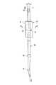
図1に示すように、処置システム10は、処置装置12と、電源を含むコントローラ14とを有する。本実施形態に係る処置装置12は、超音波振動及び高周波エネルギにより生体組織を処置可能である例について説明する。もちろん、処置装置12は、超音波振動のみにより生体組織を処置可能であってもよい。(1st Embodiment)
First, a first embodiment will be described with reference to FIGS.
As shown in FIG. 1, the
処置装置12は、処置具22と、処置具22に固定されて用いられる振動子ユニット24とを有する。振動子ユニット24は後述する振動子64を内蔵し、コントローラ14に接続される。このため、コントローラ14から供給される電力により、振動子ユニット24の振動子64に適宜の周波数の超音波振動を発生させることができる。また、処置具22及び振動子ユニット24は、公知の機構により、後述する長尺の振動伝達部82と後述する高周波電極を有するジョー46との間の生体組織に高周波エネルギを供給可能である。 The
処置具22は、第1ボタン26a及び第2ボタン26bを有する。第1ボタン26a及び第2ボタン26bはそれぞれ振動子ユニット24を介してコントローラ14に電気的に接続されている。例えば第1ボタン26aを押圧すると、生体組織を間に配置した状態の後述する高周波電極間に、高周波エネルギが出力される。このため、処置具22は、第1ボタン26aを押圧することで、例えば血管を止血する。第2ボタン26bを押圧すると、生体組織を間に配置した状態の高周波電極間に高周波エネルギが出力されるとともに、振動子ユニット24に振動を発生させる電力を出力する。このため、処置具22は、第2ボタン26bを押圧することで、例えば血管を主として高周波エネルギで止血しながら、主として超音波振動の作用で切開することができる。 The
処置具22は、シャフト34を有するハウジング32を有する。ハウジング32は医師などのユーザに把持される把持部として形成されている。ハウジング32は電気絶縁性を有する樹脂材で形成されている。 The
シャフト34は、プローブ42と、プローブ42の後述する振動伝達部82の外周を覆う筒状部(シース)44とを有する。 The
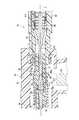
図2に示すように、ハウジング32には、シャフト34の筒状部44が支持されている。筒状部44自体は例えばステンレス鋼材などの金属材で形成されている。筒状部44の外周面は患者に当接される可能性がある。このため、筒状部44の外周面は樹脂材でコーティングされるなど、電気絶縁性を有する。 As shown in FIG. 2, the
筒状部44の先端部には、ジョー46が長手軸Lの軸方向に直交する枢支軸の軸周りに回動可能に支持されている。ジョー46は、長手軸Lに沿って移動可能な後述する可動筒状部74により位置が操作される。この可動筒状部74は、ハウジング32の内部のスライダ76により、後述する可動ハンドル56に連動して移動する。 A
ジョー46のうち、高周波電極として用いられる振動伝達部82に対向する部位には、振動伝達部82とは異なる極の高周波電極が設けられている。 A portion of the
なお、可動筒状部74のうち、回転ノブ58から先端側に突出した部位の外周は、外周面が絶縁コーティングされたステンレス鋼材製の筒状部材79(図1参照)で覆われている。図示しないが、振動伝達部82と可動筒状部74との間には、内側筒状体が配設されている。振動伝達部82の外周面のうち、振動の節Pとなる位置の外周面には、内側筒状体の内周面との間のスペーサとして用いられるゴムライニング83(図3A参照)が配設されている。なお、振動伝達部82の外周面のうち、振動の節Pとなる位置の外周面には、凹部82cが形成され、ゴムライニング83の長手軸Lに沿った移動を抑制している。 The outer periphery of a portion of the movable
公知であるので、適宜に説明を省略するが、ハウジング32は、本体(把持体)52と、本体52に設けられた固定ハンドル54とを有する。ハウジング32には、可動ハンドル56が配設されている。可動ハンドル56は固定ハンドル54に対して離隔する状態に付勢されている。このとき、筒状部44の先端のジョー46は振動伝達部82のエンドエフェクタ94に対して離隔している。ユーザ(医師)は、可動ハンドル56を固定ハンドル54に対して近づけることができる。この操作に連動して、筒状部44の先端のジョー46が長手軸Lの軸方向に直交する枢支軸の軸周りに回動し、振動伝達部82のエンドエフェクタ94に近接する。 Although the description is appropriately omitted because it is publicly known, the
同様に、公知であるので、適宜に説明を省略するが、ハウジング32の筒状の本体52には、長手軸Lと同軸上に回転操作ノブ58が設けられている。回転ノブ58はハウジング32の本体52に対して長手軸Lの軸周りに回転可能である。このとき、後述するように、回転ノブ58の回転に伴って、筒状部44、ジョー46及びプローブ42が一緒に回転する。回転ノブ58の回転に伴って、筒状部44、ジョー46及びプローブ42だけでなく、振動子ユニット24も一緒に回転する。 Similarly, the description is appropriately omitted because it is publicly known, but a
振動子ユニット24は、ケース62と、ケース62の内側に配設され電力の供給により超音波振動を発生する振動子64と、振動子64に固定され振動子64で発生した振動(縦振動)を伝達する振動子側伝達部66とを有する。振動子側伝達部66の基端は振動子64に固定されている。振動子側伝達部66の先端には振動伝達部82に着脱可能に固定される接続部66aが形成されている。ここでは、接続部66aは雌ネジとして形成されている。接続部66aは、振動子64からの振動が伝達されたときに振動の腹に相当する。 The
シャフト34の筒状部(外装部材)44は、電気絶縁性を有する材料から形成されるホルダ(外装部材)72と、ホルダ72の外側に設けられる可動筒状部74とを有する。可動筒状部74は、導電材料で形成され、振動子ケース62及びホルダ72に対して長手軸Lに沿って移動可能である。可動筒状部74の外周には、絶縁材料から形成されるスライダ76が設けられている。スライダ76は、可動筒状部74に対して長手軸Lに沿って移動可能である。スライダ76と可動筒状部74との間は、コイルバネ等の弾性部材76aを介して接続されている。また、スライダ76には可動ハンドル56が取り付けられている。可動ハンドル56を固定ハンドル54に対して開閉させることにより、スライダ76に駆動力が伝達され、スライダ76が長手軸Lに沿って移動する。そして、弾性部材76aを介してスライダ76から可動筒状部74に駆動力が伝達され、可動筒状部74が振動子ケース62及びホルダ72に対して長手軸Lに沿って移動する。 The cylindrical portion (exterior member) 44 of the
振動子ケース62には、導電部62aが形成されている。導電部62aはコントローラ14に電気的に接続されている。また、振動子ケース62に筒状部44が接続された状態では、筒状部44の可動筒状部74が振動子ケース62の導電部62aに移動可能に当接する。このため、振動子ケース62に筒状部44が接続された状態では、振動子ケース62と可動筒状部74との間は、電気的に接続される。これにより、コントローラ14から振動子ケース62の導電部62aを通って、筒状部44の可動筒状部74に高周波電流が供給される。なお、振動子ケース62の導電部62a及び筒状部44の可動筒状部74は、振動伝達部82に対して、電気的に絶縁されている。 In the
図3Aに示すように、プローブ42は、振動子ユニット24に発生させた超音波振動を伝達する振動伝達部(本体部)82と、振動伝達部82の外部に取り付けられた係合部材84とを有する。振動伝達部82は、振動伝達性、強度、発熱性、生体適合性等を考慮して、チタン又はチタン合金材製の円柱状ロッド(丸棒)が適宜に加工されて形成される。ここでは、振動伝達部82は、Ti−6Al−4V合金などのα−βチタン合金材を用いる例について説明する。円柱状ロッドは、振動伝達部82の最大外径Dを規定する。 As shown in FIG. 3A, the
振動伝達部82は、先端82a及び基端82bにより長手軸Lが規定される。振動伝達部82の長手軸Lは、先端82aから基端82bまで略真っ直ぐに形成されていても良く、後述するエンドエフェクタ94の基端よりも基端側では略真っ直ぐに形成され、先端82aを含むエンドエフェクタ94では曲げられていても良い。 The longitudinal axis L of the
振動伝達部82の先端82aと基端82bとの間の距離、すなわち、振動伝達部82の長さは、振動伝達部82の最大外径(円柱状ロッドの最大外径)Dに対して長く形成されている。振動伝達部82の基端82bを含む基端部には振動子ユニット24が固定される接続部92が形成されている。接続部92は例えば雄ネジとして形成されている。 The distance between the
振動伝達部82の先端82aを含む先端部には、超音波振動が基端82bから先端82aに伝達されることにより、生体組織に適宜の処置を行うエンドエフェクタ94が形成されている。エンドエフェクタ94は、適宜の形状に形成される。ここでのエンドエフェクタ94は、視認性を考慮して先端が曲げられている。そして、エンドエフェクタ94はジョー46に対して噛み合わせられる所定の形状に形成されている。 An
振動伝達部82は、振動子ユニット24に振動を発生させた際の周波数(波長)に合わせて長さが調整されている。特に、振動伝達部82は、振動伝達部82の基端82bから先端82aに向かって振動を伝達させたときに、例えば基端82bが長手軸Lに沿って振動(縦振動)する、振動の腹位置またはその近傍となるように長さが調整されている。 The length of the
なお、振動伝達部82は、公知のプローブと同様に、その基端82bからエンドエフェクタ94の基端までの間に、一部の形状を先端側に向かうにつれて小径にテーパ状に加工するなど、振動が伝達されたときに適宜に振幅を拡大させる部位が形成されていることも好適である。 In addition, like the known probe, the
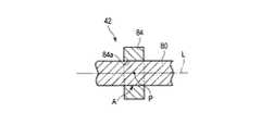
係合部材84は、振動伝達部82の基端82bから先端82aに向かって振動を伝達させたときに振動しない振動の節Pとなる位置の外周及び/又はその近傍に固定されている。このため、係合部材84は、振動伝達部82の外周面に対して、図5Bに示す領域Aの範囲に固定されている。 The
なお、図5Cに示す係合部材84は、長手軸Lに沿う方向に筒状体84bを有する。筒状体84bの外周面は係合部材84の外周面と面一に形成されている。一方、筒状体84bの内周面は貫通穴84aよりも径方向外方にある。この場合、係合部材84が振動伝達部82の外周面に対して固定される範囲Aは、筒状体84bを除く部位である。 The
係合部材84は、筒状部(外装部材)44に支持される。このため、プローブ42は筒状部44に支持される。係合部材84は、筒状部44に対して勝手に、長手軸Lの軸方向への移動及び軸周りへの回転が防止される形状に形成されている。このため、係合部材84の外縁は、筒状部44に対する回転を規制するため、円形以外に形成されている。図3A及び図3Bに示すように、一例として、係合部材84の外形は、略直方体状に形成されている。係合部材84は、振動伝達部82のうち、円柱状ロッドの外径Dと略同じ外径を有する部分に配置されるので、円柱状ロッドの外径Dと同じか僅かに小さい円形状の貫通穴84aを有する。すなわち、係合部材84の貫通穴84aは、振動伝達部82を内側に配置可能である。 The
係合部材84は、後述する種々の固定方法又はその組み合わせにより、振動伝達部82の外周にしっかりと固定され、筒状部44に対してしっかりと支持され、振動を吸収し難い素材が用いられる。係合部材84には金属材が用いられることが好適である。係合部材84には、例えば金属材として、アルミニウム合金材が用いられることが好ましい。そして、係合部材84は、アルミニウム合金材のうち、強度が高い、ジュラルミンが用いられることが好ましい。その他、係合部材84には、ジュラルミンとは異なる超ジュラルミン又は超々ジュラルミンが用いられることも好ましい。また、係合部材84には、チタン又はチタン合金が用いられることも好ましい。係合部材84としては、超音波振動の減衰率が振動伝達部82と同程度若しくは振動伝達部82よりも小さい材料で形成される。このため、係合部材84としては、振動伝達部82より減衰率が大きく剛性が低いゴム材や一般的な樹脂材を用いるのは不適である。その他、係合部材84として、金属であっても一部の鉄、ステンレス合金材又はマグネシウム合金材で、減衰が大きい材質を用いることは避けた方が良い。これらの素材は、振動を吸収し易いので結果として発熱し易く、外挿部材を保持しにくいなどの課題があるからである。
但し、例えばステンレス合金やマグネシウム合金材にも、振動吸収性が低い素材がある。このため、一見同様な合金材であっても振動の減衰率が小さい素材を選択することにより、係合部材84が形成されることは好適である。同様に、係合部材84は、物性的には、セラミックスやガラス等の他の無機材料や、PPS(ポリフェニレンサルファイド)のように音響減衰が小さく(低減衰であり)、剛性・硬度が高い(高剛性である)樹脂材料であれば振動条件により使用可能である。The engaging
However, there is a material having low vibration absorption, for example, also in a stainless alloy or a magnesium alloy material. Therefore, it is preferable that the engaging
なお、円柱状ロッドは、係合部材84が固定された後に加工されて所望の形状の振動伝達部82を形成しても良く、円柱状ロッドは、係合部材84が固定される前に加工されて所望の形状の振動伝達部82を形成した後、振動伝達部82に係合部材84を固定しても良い。また、円柱状ロッドの加工の中間段階で振動伝達部82に係合部材84を固定しても良い。 Note that the cylindrical rod may be processed after the
図3Aから図5Aに示すように、ホルダ72は、第1分割体77と、第1分割体78とを有する。第1分割体77及び第1分割体78はそれぞれ略ハーフパイプ状に形成されている。このため、ホルダ72は、第1分割体77の縁部77aと第1分割体78の縁部78aとを嵌合させると、筒状となる。 As shown in FIGS. 3A to 5A, the
第1分割体77及び第1分割体78は、係合部材84が嵌合される凹溝77b,78bを有する。凹溝77b,78bは互いに対向するので、第1分割体77及び第2分割体78は協働して係合部材84を保持する。このため、ホルダ72は、振動伝達部82の外部に配設される。The first divided
一例として、ホルダ72は外周に1対の平面77c,78cを有する。このため、第1分割体77の平面77cが可動筒状部74の内周面に嵌合し、第2分割体78の平面78cが可動筒状部74の内周面に嵌合することで、ホルダ72は可動筒状部74に嵌合されている。可動筒状部74は、公知の機構により回転操作ノブ58に支持されている。 As an example, the
次に、振動伝達部82の外周の適宜の位置に係合部材84を固定する場合の固定方法について簡単に説明する。 Next, a method of fixing the engaging
図6に示すように振動伝達部82を形成する。まず、チタン合金材製の、適宜の長さの円柱状ロッドを準備する。円柱状ロッドの長さは、最終製品としての振動伝達部82の長さと略同じ又はそれよりも僅かに長く形成されている。また、最終製品としての振動伝達部82の外径は、円柱状ロッドの外径Dと同じ外径部分が極力長く形成されていることが好ましい。この場合、プローブ42の振動伝達部82の材料費を抑制し、加工量を減らすことができる。本実施形態に係るプローブ42は、振動伝達部82の外周面に対して、係合部材84の外周の一部が距離T(図4参照)の状態にある。このため、従来の振動伝達部に対して、径方向に例えば距離T分の素材を節約でき、かつ、加工量を減らすことができる。 As shown in FIG. 6, the
円柱状ロッドの外周面は適宜の平滑円柱面として形成されている。振動伝達部82が長手軸Lに対して対称に形成され、長手軸Lに直交する断面は長手軸Lを中心として円形状に形成されている。このため、振動伝達部82が長手軸Lに対して対称に形成されている。このように、振動伝達部82の対称性が高いため、振動伝達部82の基端82bから先端82aに向かって振動を伝達すると、横振動の発生を抑制でき、振動を安定させることができる。 The outer peripheral surface of the cylindrical rod is formed as a suitable smooth cylindrical surface. The
なお、円柱状ロッドの半径は、振動伝達部82の想定するエンドエフェクタ94のうちの長手軸Lから最も離れた位置の半径と同じか、削られることを想定して僅かに大きく形成されている。 The radius of the cylindrical rod is formed to be the same as the radius of the
ここでは、焼き嵌めにより、振動伝達部82の所定位置(振動を伝達させたと仮定したときに、振動の節Pとなる位置及び/又はその近傍)に係合部材84を固定する例について説明する。 Here, an example will be described in which the
円柱状ロッドの基端82bに対して、仮に振動子ユニット24を接続したと仮定する。このとき、振動子ユニット24に振動を発生させて振動伝達部82に振動を伝達したと仮定したときの、振動の節Pとなる位置の外周及び/又はその近傍に、係合部材84を固定する。振動の節が複数形成される場合、例えば最も基端側の振動の節Pとなる位置の外周及び/又はその近傍に係合部材84を固定する。 It is assumed that the
係合部材84が固定されるのは、振動が伝達されたときに振動の節Pとなる位置であることが好ましい。ここで、振動の節Pは点として規定されるものである。係合部材84は長手軸Lに沿って適宜の厚さを有するため、振動の節Pとなる位置の外周だけでなく、その近傍に連続した位置にも、係合部材84は固定されることになる。 It is preferable that the
また、係合部材84は、振動の節Pとなる位置の外周ではなく、その近傍に固定されることも好適である。すなわち、係合部材84が固定されるのは、振動の節Pとなる位置の外周に限られず、多少のズレは許容される。 Further, it is preferable that the
係合部材84は適宜の熱を負荷すると、僅かに膨張する。このため、貫通穴84aの内径は僅かに大きくなる。この状態で、係合部材84の貫通穴84aに振動伝達部82を通すとともに、係合部材84の貫通穴84aのうち、長手軸Lに沿った方向の中央を、振動伝達部82の振動の節Pとなる位置の外周及びその近傍に配置する。この状態で係合部材84を冷やしていくと、係合部材84が振動伝達部82の振動の節Pとなる位置の外周を含む位置に固定される。 When an appropriate heat is applied, the
このとき、円柱状ロッドの外周面は適宜の平滑円柱面として形成されている。振動伝達部82が長手軸Lに対して対称に形成され、対称性が高いため、超音波振動を伝達したときに振動を安定させることができる。また、振動伝達部82と係合部材84との間に接着剤等の振動の伝達に影響を及ぼし得る介在物が存在しない。このため、振動伝達部82の基端82bから先端82aに向かって伝達する振動のロスを抑制することができる。 At this time, the outer peripheral surface of the cylindrical rod is formed as an appropriate smooth cylindrical surface. Since the
そして、エンドエフェクタ94は、適宜の形状に削られるなどして所望の形状に形成される。振動伝達部82の外周に係合部材84を配置した後にエンドエフェクタ94を形成しても良く、振動伝達部82にエンドエフェクタ94を形成した後に振動伝達部82の外周に係合部材84を配置しても良く、振動伝達部82にエンドエフェクタ94を形成する工程の途中で振動伝達部82の外周に係合部材84を配置しても良い。 Then, the
このようにプローブ42を形成しても、係合部材84の先端からエンドエフェクタ94の先端までの間の外径等は従来のプローブと略同一に形成している。このため、振動伝達部82の強度は、従来と同程度に維持することができる。すなわち、エンドエフェクタ94の強度は、従来と同程度に維持することができる。 Even when the
このように形成されたプローブ42は、図1及び図2に示すように、ハウジング32に配設される。 The
そして、振動子ユニット24の振動子側伝達部66の先端の接続部(雌ネジ)66aに、プローブ42の振動伝達部82の基端82bの接続部(雄ネジ)92が螺合される。このとき、ハウジング32に振動子ユニット24が固定される。振動伝達部82は振動子側伝達部66に電気的に接続されている。このため、第1ボタン26aを押圧すると、振動伝達部82のエンドエフェクタ94は高周波電極として使用される。また、第2ボタン26bを押圧すると、振動伝達部82のエンドエフェクタ94が高周波電極として使用されるとともに、振動子64に発生させた超音波振動が伝達される。このため、エンドエフェクタ94は高周波電極として用いられながら、長手軸Lの軸方向に縦振動する。 Then, a connection portion (male screw) 92 of the
以上説明したように、この実施形態に係る処置具22によれば、以下のことが言える。 As described above, according to the
例えば振動伝達部82に用いられるチタン材(チタン合金材)は、素材自体が高価であるとともに、加工し難いため、高コストになることが知られている。従来は、例えば最大外径が8mmの円柱状ロッドを加工してプローブを形成する場合、外装部材と係合する係合部の最大外径は8mm又はそれに近い状態に維持される。一方、係合部を除く部位(例えば先端側のある部位)は、例えば外径が4mmなど、最大外径が8mmの場合に比較して、面積比で1/4しか残されないことになる。この場合、円柱状ロッドは、面積比で3/4は加工により除去することが必要になる。そして、係合部はプローブの基端部近傍に形成されることが多いため、プローブが長くなればなるほど素材のロスが大きくなることは容易に想像される。 For example, it is known that the titanium material (titanium alloy material) used for the
本実施形態では、振動伝達部82の外周に係合部材84を後から固定して、プローブ42を形成することができる。このため、円柱状ロッドに切削等の加工を施して係合部材84を形成する必要がない。したがって、円柱状ロッドの外周面と係合部材84の外周の一部との間の距離Tの分の素材の切削を省略することができる。素材の円柱状ロッドの加工量を極力少なくして、プローブ42を形成することができる。例えば、従来は最大外径が8mmの円柱状ロッドを加工していたものを、予め、4mmの円柱状ロッドを使用して、プローブ42を形成することができる。このため、本実施形態に係る構造を有するプローブ42によれば、素材のロスを極力低減することができるとともに、加工賃も抑制することができる。したがって、本実施形態によれば、加工量を極力少なくしながら、例えばハウジング32及び/又は回転ノブ58等の外装部材に係合可能なプローブ42を提供することができる。 In the present embodiment, the
なお、プローブ42をこのように形成しても、係合部材84の先端からエンドエフェクタ94の先端までの間の外径等は従来のプローブと略同一に形成している。このため、振動伝達部82のエンドエフェクタ94の強度は、従来と同程度に維持することができる。 Even when the
(第1変形例)
図7A及び図7Bに示すように、振動伝達部82の外周面のうち、係合部材84が取り付けられる位置(振動の節Pとなる位置の外周面)は加工され、多角形に形成されていることも好適である。このとき、係合部材84の貫通穴84aも同じ多角形に形成されている。ここでは、多角形は正六角形であり、振動伝達部82は、外周面に、第1から第6面182a−182fを有する。このため、振動伝達部82の外周と係合部材84の貫通穴84aの内周面の第1から第6面184a−184fとの間は、平面同士が当接される嵌合構造により嵌合される。したがって、振動伝達部82に係合部材84を固定した状態で、振動伝達部82に対して係合部材84が長手軸Lの軸回りの周方向に移動するのを抑制することができる。(First Modification)
As shown in FIG. 7A and FIG. 7B, of the outer peripheral surface of the
図7A及び図7B中には、振動伝達部82の全周にわたって機械構造的に、振動伝達部82に対する係合部材84の保持強度を高める構造を示している。図8A及び図8Bに示す例は、振動伝達部82の一部に、機械構造的に、振動伝達部82に対する係合部材84の保持強度を高める構造を示している。振動伝達部82は、図8A及び図8Bに示すように、互いに反対方向に法線が向けられる1対の平面182a,182bを有する。第1平面182aに係合部材84の第1嵌合平面184aが嵌合され、第2平面182bに係合部材84の第2嵌合平面184bが嵌合される。 7A and 7B show a structure that mechanically increases the holding strength of the engaging
同様に、図9A及び図9Bには、図8A及び図8Bで示した平面の代わりに、曲面を用いた例である。このような形状であっても、機械構造的に、振動伝達部82に対する係合部材84の保持強度を高めることができる。 Similarly, FIGS. 9A and 9B show examples using curved surfaces instead of the planes shown in FIGS. 8A and 8B. Even with such a shape, the holding strength of the
(第2変形例)
振動伝達部82に対して係合部材84を固定する際、接着により固定することができる。例えば空気を遮断することで硬化する嫌気性接着剤を用いることで、振動伝達部82と係合部材84との間が高強度に固定される。また、嫌気性接着剤の接着時間は、例えばエポキシ系などの接着剤に比べて短くすることができるため、組立時間の短縮を図ることができる。なお、嫌気性接着剤は、厚さが薄いほど固まり易い。このため、嫌気性接着剤は、振動伝達部82と係合部材84との間に極めて薄く形成されていれば良い。したがって、嫌気性接着剤は、振動伝達部82と係合部材84との間の振動ロスの発生の原因となり難い。(Second Modification)
When the engaging
(第3変形例)
振動伝達部82及び係合部材84がともにチタン合金材のような同種材料の場合、レーザ溶接等の溶接により、振動伝達部82と係合部材84との間を高強度に固定することができる。この場合、焼きなまし等により、振動伝達部82と係合部材84との間の溶接により生じた残留応力を取り除いておくことが好ましい。(Third Modification)
When the
振動伝達部82がチタン合金材で、係合部材84がアルミニウム合金材であるような異種材料であっても、ロウ付けにより振動伝達部82と係合部材84との間が高強度に固定される。 Even if the
係合部材84がアルミニウム合金材等、比較的融点が低い素材で形成する場合、鋳造により、振動伝達部82に係合部材84を形成することができる。この場合、振動伝達部82に係合部材84が一体化され、高い密着性を得ることができる。 When the engaging
係合部材84が振動伝達部82よりも低温で変形する素材で形成される場合、例えばHIP法(熱間静水圧プレス法)を用いて振動伝達部82に係合部材84を形成することができる。この場合、振動伝達部82に係合部材84が一体化され、高い密着性を得ることができる。 When the engaging
係合部材84が振動伝達部82よりも軟らかい素材で形成される場合、例えばCIP法(冷間静水圧プレス法)を用いて振動伝達部82に係合部材84を形成することができる。この場合、室温で振動伝達部82に係合部材84を形成するため、温度の影響を抑制することができる。 When the engaging
係合部材84は、金属溶融粉、レーザ粉末冶金等により、振動伝達部82の外周に公知の3D成形技術により直接的に形成されることにより、適宜の複雑な形状に形成することができる。 The engaging
(第4変形例)
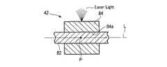
その他、図10A及び図10Bに示すように、係合部材84の一部を塑性変形させて、振動伝達部82に対する保持力を発揮させるようにしても良い。例えば、図10Aに示すように、筒状の係合部材84を振動伝達部82の外周に配置する。そして、レーザ光を係合部材84の外周面に照射し、係合部材84の結晶構造を変化させる。具体的には、係合部材84の外周を、周方向に沿って加熱させて膨張させる。このため、図10Bに示すように、レーザ光が照射された位置に隣接する先端側及び基端側の位置は、振動伝達部82の外周を保持する応力が働く。このような塑性加工により、振動伝達部82の外周に適宜に係合部材84を固定することができる。(Fourth modification)
In addition, as shown in FIGS. 10A and 10B, a part of the engaging
なお、図10Cに示すように、振動の節Pの外周に相当する位置から長手軸Lに沿ってずれた領域A1,A2を係合部材84で保持することも好ましい。この場合、係合部材84は、複数の位置で振動伝達部82を保持しているので、保持力を高めることができる。また、係合部材84は、振動伝達部82の長手軸Lに沿って、振動の節Pを避けた位置を保持している。このため、振動伝達部82の径方向振動を外部に伝え難くすることができる。そして、振動伝達部82に超音波振動が伝達されたときに振動伝達部82が振動伝達部82の長手軸Lに直交する径方向に変位するのを許容することができる。As shown in FIG. 10C, it is also preferable that the
(第5変形例)
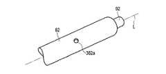
図11A及び図11Bに示すように、振動伝達部82の一部に凹溝282aを形成する。このとき、係合部材84の貫通穴84aの内周面には、突起284aが形成されていることが好適である。このため、凹溝282aに突起284aが係合されることにより、係合部材84を振動伝達部82に対してより強固に固定することができる。(Fifth Modification)
As shown in FIGS. 11A and 11B, a
なお、図12A及び図12Bに示すように、凹溝282a及び突起284aは長手軸Lに平行、すなわち真っ直ぐに形成される必要はなく、螺旋状など、適宜に形成されていれば良い。 As shown in FIGS. 12A and 12B, the
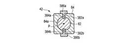
図13A及び図13Bに示すように、係合部材84を振動伝達部82に固定する際、キーやピン等の補助部材を用いることができる。この場合、係合部材84を振動伝達部82に固定する際に加温するなど、係合部材84及び振動伝達部82に、意図しない熱的な影響が及ぼされるのを防止できる。 As shown in FIGS. 13A and 13B, when fixing the
具体的には、振動伝達部82は、例えば1対の凹孔382a,382bを有する。係合部材84は、凹孔382a,382bに連通する貫通孔384a,384bを有する。貫通孔384a,384bは長手軸Lに直交する方向に形成されている。そして、第1ピン386aが貫通孔384a及び凹孔382aに固定され、第2ピン386bが貫通孔384b及び凹孔382bに固定される。 Specifically, the
図14A及び図14Bに示す例のように、振動伝達部82の長手軸Lに直交する方向に凹溝482a,482bが形成されている場合、例えば略U字状の係合部材84を用いても良い。係合部材84は、脚部484a,484bを有する。脚部484a,484bが凹溝482a,482bに嵌合されて、振動伝達部82に係合部材84が固定される。When the
(第6変形例)
図15A及び図15Bに示す例では、係合部材84は板金加工により形成されている。係合部材84は、ハブ584aと、ハブ584aの外側に延出された複数のウィング584bとを有する。係合部材84は、開口84aを有する十字状のプレートが適宜に折り曲げられて形成されている。このような係合部材84は、適宜のホルダ72に嵌合されて保持される。(Sixth modification)
In the example shown in FIGS. 15A and 15B, the
例えば振動の節Pとなる位置から長手軸Lに沿ってずれた位置の外周を係合部材84で保持する場合、振動伝達部82の径方向の振動を外部に伝え難くすることができる。 For example, when the outer periphery at a position shifted along the longitudinal axis L from the position serving as the node P of vibration is held by the
(第7変形例)
図16に示す例では、係合部材84の一部を薄肉にしている。ここでは、係合部材84は、貫通穴84aを形成する内筒684aと、内筒684aの外周に離間して形成された外筒684bとを有する。ホルダ72は、外筒684bの外周面に嵌合される。内筒684aと外筒684bとの間は離間しているので、振動伝達部82に伝達される振動をホルダ72などの外部に伝え難くすることができる。(Seventh modification)
In the example shown in FIG. 16, a part of the engaging
以上説明したように、振動伝達部82に超音波振動を伝達したときに振動の節Pとなる位置の外周の位置及び/又はその近傍に係合部材84を固定したり、成形したりして配置してプローブ42を形成する種々の方法が許容される。係合部材84としては、発熱を考慮して、超音波振動の減衰率が振動伝達部82と同程度若しくは振動伝達部82よりも小さい材料で形成される。 As described above, when the ultrasonic vibration is transmitted to the
なお、プローブ42の係合部材84の外形は、略直方体状であるとして説明したが、ホルダ72との関係で適宜に設定可能である。 Although the outer shape of the
(第2実施形態)
次に、第2実施形態について図17から図18Bを用いて説明する。この実施形態は第1実施形態の変形例であって、第1実施形態で説明した部材と同一の部材又は同一の機能を有する部材には同一の符号を付し、詳しい説明を省略する。(2nd Embodiment)
Next, a second embodiment will be described with reference to FIGS. 17 to 18B. This embodiment is a modification of the first embodiment, and the same members as those described in the first embodiment or members having the same functions are denoted by the same reference numerals, and detailed description will be omitted.
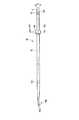
第1実施形態では、振動伝達部82のエンドエフェクタ94とジョー46との間に生体組織を挟んで処置を行う処置具22の例について説明したが、ここでは、主に長手軸Lに沿って移動させることにより処置を行う処置具122の例について説明する。そして、ここでは、ハウジング32には、回転ノブ58が配設されていない。 In the first embodiment, the example of the
図17に示すように、処置システム10は、処置装置12と、電源を含むコントローラ14と、フットスイッチ16とを有する。処置装置12は、処置具122と、処置具122に固定されて用いられる振動子ユニット24とを有する。 As shown in FIG. 17, the
図17に示す処置具122は、ユーザ(医師)が生体組織にエンドエフェクタ194を接触させた状態でフットスイッチ16を押圧すると、処置具122のプローブ42に超音波振動が伝達される。そして、ユーザは、プローブ42に超音波振動が伝達された状態でプローブ42を長手軸Lに沿って移動することで生体組織を切削等することが可能である。In the
処置具122のプローブ42は、第1実施形態で説明したのと同様に、振動伝達部82と係合部材84とを有する。振動伝達部82と係合部材84とは別体として形成されている。The
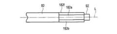
図18A及び図18Bに示す振動伝達部82は、先端82aから基端82bまで、円柱状ロッドの最大外径Dの範囲内にある。このため、例えば切削加工することにより、適宜の形状のエンドエフェクタ194を形成することができる。このとき、振動伝達部82に振動を伝達したときに振動の節Pとなる位置のうち、最も先端の位置よりも先端側にエンドエフェクタ194を形成することが好適である。 The
そして、図18A及び図18Bに示すように、振動伝達部82に超音波振動を伝達したときに振動の節Pとなる位置の外周の位置及び/又はその近傍に係合部材84を固定したり、成形したりして配置してプローブ42が形成されている。 Then, as shown in FIG. 18A and FIG. 18B, the engaging
したがって、本実施形態によれば、加工量を極力少なくしながら、例えばハウジング32等の外装部材に係合可能なプローブ42を提供することができる。 Therefore, according to the present embodiment, it is possible to provide the
そして、本実施形態に係るエンドエフェクタ194を含む振動伝達部82は、円柱状ロッドを単に切削するだけで形成することができる。なお、振動伝達部82は、適宜に熱処理を行うことで、適宜の強度、適宜の延性及び適宜の靱性を得ることができる。 The
なお、プローブ42の振動伝達部82のエンドエフェクタ194の形状は、種々の処置装置に関して適宜に設定可能である。例えばジョー46を必要としない処置装置の一つであるフック型において、エンドエフェクタ194は、引っかかり部を持つ形状に設定する。これ以外にも、エンドエフェクタ194の形状には種々の形状が許容されることは言うまでもない。このため、振動伝達部82、すなわち、共通の係合部材84を固定したプローブ42は、複数種類のラインナップに対応することができる。各プローブ42は、共通の係合部材84をホルダ72を介してハウジング32に適宜に取り付けることができる。 Note that the shape of the
これまで、幾つかの実施形態について図面を参照しながら具体的に説明したが、この発明は、上述した実施の形態に限定されるものではなく、その要旨を逸脱しない範囲で行なわれるすべての実施を含む。 So far, some embodiments have been specifically described with reference to the drawings. However, the present invention is not limited to the above-described embodiments, and all implementations that do not depart from the gist of the invention are described. including.
Claims (16)
Translated fromJapanese前記本体部に前記超音波振動が伝達されたときに前記超音波振動の節となる位置の外周及び/又はその近傍に設けられ、前記本体部における前記超音波振動の減衰率と同程度若しくは小さい材料で形成される係合部材と
を有するプローブと、
前記本体部の外部に配設され、前記係合部材に係合されるホルダを有する、外装部材と
を備え、
前記ホルダは、前記ホルダに対して前記係合部材を、前記本体部の長手軸の軸方向に沿う方向への移動を規制するとともに、前記長手軸の軸回り方向への回転を規制する、処置具。A long body that transmits ultrasonic vibrations,
When the ultrasonic vibration is transmitted to the main body, the ultrasonic vibration is provided at and / or in the vicinity of a position serving as a node of the ultrasonic vibration, and is substantially equal to or smaller than the attenuation rate of the ultrasonic vibration in the main body. A probe having an engagement member formed of a material;
An exterior member provided outside the main body portion and having a holder engaged with the engagement member,
The treatment, wherein the holder regulates movement of the engagement member with respect to the holder in a direction along an axial direction of a longitudinal axis of the main body, and regulates rotation of the longitudinal axis in a direction around the axis. Utensils.
前記係合部材は、アルミニウム合金で形成されている、請求項1に記載の処置具。The main body is formed of titanium or a titanium alloy,
The treatment tool according to claim 1, wherein the engagement member is formed of an aluminum alloy.
前記本体部に前記超音波振動が伝達されたときに、前記先端部及び前記基端部はそれぞれ振動の腹位置に相当する、請求項1に記載の処置具。The main body portion has an end effector at a distal end portion, and has a connection portion connected to a vibrator unit that generates the ultrasonic vibration at a base end portion,
The treatment tool according to claim 1, wherein, when the ultrasonic vibration is transmitted to the main body, the distal end and the proximal end correspond to antinode positions of the vibration, respectively.
前記係合部材は、前記外装部材の内側に係合され、
前記本体部は、前記超音波振動を発生する振動子ユニットが基端に接続され、前記超音波振動が先端に伝達される、円柱状ロッドで形成された長尺であり、
前記円柱状ロッドは最大外径を規定し、
前記本体部は、前記係合部材が設けられた位置の先端側及び基端側の少なくとも一方の少なくとも一部が前記円柱状ロッドの最大外径若しくは前記円柱状ロッドの最大外径よりも僅かに小さい外径に形成されている、請求項1に記載の処置具。The exterior member is a tubular shape having electrical insulation properties,
The engagement member is engaged inside the exterior member,
The main unit is a long unit formed of a cylindrical rod, wherein the vibrator unit that generates the ultrasonic vibration is connected to a base end, and the ultrasonic vibration is transmitted to a front end,
The cylindrical rod defines a maximum outer diameter,
At least a part of at least one of the distal end side and the proximal end side of the position where the engaging member is provided is slightly smaller than the maximum outer diameter of the cylindrical rod or the maximum outer diameter of the cylindrical rod. The treatment tool according to claim 1, wherein the treatment tool has a small outer diameter.
前記プローブの基端に接続される振動子ユニットと
を有する処置装置。A treatment tool according to claim 1;
A transducer unit connected to a base end of the probe.
Applications Claiming Priority (1)
| Application Number | Priority Date | Filing Date | Title |
|---|---|---|---|
| PCT/JP2016/070584WO2018011896A1 (en) | 2016-07-12 | 2016-07-12 | Probe, treatment tool and treatment device |
Publications (2)
| Publication Number | Publication Date |
|---|---|
| JPWO2018011896A1 JPWO2018011896A1 (en) | 2019-05-30 |
| JP6647401B2true JP6647401B2 (en) | 2020-02-14 |
Family
ID=60951683
Family Applications (1)
| Application Number | Title | Priority Date | Filing Date |
|---|---|---|---|
| JP2018527295AActiveJP6647401B2 (en) | 2016-07-12 | 2016-07-12 | Probe, treatment tool and treatment device |
Country Status (5)
| Country | Link |
|---|---|
| US (2) | US11065025B2 (en) |
| EP (1) | EP3485822A4 (en) |
| JP (1) | JP6647401B2 (en) |
| CN (1) | CN109475365B (en) |
| WO (1) | WO2018011896A1 (en) |
Families Citing this family (4)
| Publication number | Priority date | Publication date | Assignee | Title |
|---|---|---|---|---|
| US20220265342A1 (en)* | 2021-02-24 | 2022-08-25 | Olympus Medical Systems Corp. | Treatment device with damping feature |
| US12171454B2 (en) | 2021-02-25 | 2024-12-24 | Olympus Corporation | Curved ultrasonic transmission member having improved vibration control |
| JP7487410B2 (en) | 2021-05-07 | 2024-05-20 | オリンパス株式会社 | Ultrasonic treatment device probe, manufacturing method thereof, and ultrasonic treatment device |
| CN115702814A (en)* | 2021-08-12 | 2023-02-17 | 奥林巴斯医疗株式会社 | Ultrasonic treatment instrument |
Family Cites Families (16)
| Publication number | Priority date | Publication date | Assignee | Title |
|---|---|---|---|---|
| JP2886656B2 (en)* | 1990-10-19 | 1999-04-26 | スズキ株式会社 | Ultrasonic cutter |
| JP2886657B2 (en)* | 1990-10-19 | 1999-04-26 | スズキ株式会社 | Ultrasonic cutter |
| JP3310532B2 (en)* | 1995-04-06 | 2002-08-05 | オリンパス光学工業株式会社 | Ultrasonic incision coagulation device |
| US5971949A (en)* | 1996-08-19 | 1999-10-26 | Angiosonics Inc. | Ultrasound transmission apparatus and method of using same |
| US5776155A (en) | 1996-12-23 | 1998-07-07 | Ethicon Endo-Surgery, Inc. | Methods and devices for attaching and detaching transmission components |
| US5938633A (en)* | 1997-07-09 | 1999-08-17 | Ethicon Endo-Surgery, Inc. | Ultrasonic surgical devices |
| AU1817599A (en)* | 1997-12-11 | 1999-06-28 | Sonics & Materials Inc. | Sheath and support for ultrasonic elongate tip |
| US8152825B2 (en) | 2005-10-14 | 2012-04-10 | Ethicon Endo-Surgery, Inc. | Medical ultrasound system and handpiece and methods for making and tuning |
| US8430898B2 (en)* | 2007-07-31 | 2013-04-30 | Ethicon Endo-Surgery, Inc. | Ultrasonic surgical instruments |
| US20110201887A1 (en) | 2008-10-17 | 2011-08-18 | Koninklijke Philips Electronics N.V. | Interlocking nested cannula |
| JP2010167084A (en) | 2009-01-22 | 2010-08-05 | Olympus Corp | Ultrasonic surgical apparatus |
| US9393037B2 (en)* | 2012-06-29 | 2016-07-19 | Ethicon Endo-Surgery, Llc | Surgical instruments with articulating shafts |
| JP6086742B2 (en)* | 2013-01-29 | 2017-03-01 | オリンパス株式会社 | Ultrasonic vibration device and ultrasonic medical device |
| CN105848600B (en)* | 2014-03-03 | 2019-05-03 | 奥林巴斯株式会社 | Ultrasonic treatment tools, probes |
| JP5933874B1 (en)* | 2014-09-05 | 2016-06-15 | オリンパス株式会社 | Treatment tool, distal probe unit and proximal probe unit |
| US10433863B2 (en)* | 2014-11-25 | 2019-10-08 | Ethicon Llc | Ultrasonic surgical instrument with blade cooling through retraction |
- 2016
- 2016-07-12JPJP2018527295Apatent/JP6647401B2/enactiveActive
- 2016-07-12WOPCT/JP2016/070584patent/WO2018011896A1/ennot_activeCeased
- 2016-07-12EPEP16908800.2Apatent/EP3485822A4/ennot_activeWithdrawn
- 2016-07-12CNCN201680087607.5Apatent/CN109475365B/enactiveActive
- 2019
- 2019-01-10USUS16/244,771patent/US11065025B2/enactiveActive
- 2019-10-07USUS16/594,356patent/US11419625B2/enactiveActive
Also Published As
| Publication number | Publication date |
|---|---|
| US20190142450A1 (en) | 2019-05-16 |
| EP3485822A4 (en) | 2020-03-18 |
| JPWO2018011896A1 (en) | 2019-05-30 |
| CN109475365A (en) | 2019-03-15 |
| US11419625B2 (en) | 2022-08-23 |
| US20200029997A1 (en) | 2020-01-30 |
| EP3485822A1 (en) | 2019-05-22 |
| CN109475365B (en) | 2022-03-11 |
| WO2018011896A1 (en) | 2018-01-18 |
| US11065025B2 (en) | 2021-07-20 |
Similar Documents
| Publication | Publication Date | Title |
|---|---|---|
| JP6647401B2 (en) | Probe, treatment tool and treatment device | |
| US9750521B2 (en) | Ultrasonic blade overmold | |
| JPH10127654A (en) | Ultrasonic treatment tool | |
| US20180014844A1 (en) | Ultrasonic surgical instrument with ad hoc formed blade | |
| US20150148832A1 (en) | Features to apply fluid to an ultrasonic blade of a surgical instrument | |
| JP2017514568A (en) | Surgical device with temperature control | |
| JP2015208710A (en) | Ultrasonic transducer and ultrasonic medical device | |
| CN109715090A (en) | End and its manufacturing method for the ultrasonic surgery tool with Surface hardened layer cutting edge | |
| EP3437574B1 (en) | Method of manufacturing ultrasonic transmission components of ultrasonic surgical instruments | |
| JP2010167084A (en) | Ultrasonic surgical apparatus | |
| JP2012527325A (en) | Coupling arrangement and method for attaching a tool to an ultrasonic surgical instrument | |
| JP6147449B2 (en) | Medical equipment and ultrasonic surgical device | |
| JP6192886B1 (en) | Vibration transmitting member, ultrasonic treatment instrument, and vibrator unit | |
| WO2016047241A1 (en) | Vibration-generating unit, vibration component unit, and ultrasonic wave processing implement | |
| US10813660B2 (en) | Ultrasonic treatment device | |
| CN109845292B (en) | Ultrasonic transducer and ultrasonic treatment system | |
| JP6980813B2 (en) | Vibration transmission member and ultrasonic treatment tool | |
| EP3406214B1 (en) | Medical apparatus, medical apparatus system | |
| WO2020152783A1 (en) | Ultrasonic treatment tool and vibration transmission member | |
| WO2022185414A1 (en) | Ultrasonic treatment tool and vibration transmission member |
Legal Events
| Date | Code | Title | Description |
|---|---|---|---|
| A521 | Request for written amendment filed | Free format text:JAPANESE INTERMEDIATE CODE: A523 Effective date:20190111 | |
| A621 | Written request for application examination | Free format text:JAPANESE INTERMEDIATE CODE: A621 Effective date:20190111 | |
| A131 | Notification of reasons for refusal | Free format text:JAPANESE INTERMEDIATE CODE: A131 Effective date:20191119 | |
| A521 | Request for written amendment filed | Free format text:JAPANESE INTERMEDIATE CODE: A523 Effective date:20191204 | |
| TRDD | Decision of grant or rejection written | ||
| A01 | Written decision to grant a patent or to grant a registration (utility model) | Free format text:JAPANESE INTERMEDIATE CODE: A01 Effective date:20191217 | |
| A61 | First payment of annual fees (during grant procedure) | Free format text:JAPANESE INTERMEDIATE CODE: A61 Effective date:20200114 | |
| R151 | Written notification of patent or utility model registration | Ref document number:6647401 Country of ref document:JP Free format text:JAPANESE INTERMEDIATE CODE: R151 | |
| R250 | Receipt of annual fees | Free format text:JAPANESE INTERMEDIATE CODE: R250 | |
| R250 | Receipt of annual fees | Free format text:JAPANESE INTERMEDIATE CODE: R250 | |
| R250 | Receipt of annual fees | Free format text:JAPANESE INTERMEDIATE CODE: R250 |