JP6647021B2 - Absorbent articles - Google Patents
Absorbent articlesDownload PDFInfo
- Publication number
- JP6647021B2 JP6647021B2JP2015227785AJP2015227785AJP6647021B2JP 6647021 B2JP6647021 B2JP 6647021B2JP 2015227785 AJP2015227785 AJP 2015227785AJP 2015227785 AJP2015227785 AJP 2015227785AJP 6647021 B2JP6647021 B2JP 6647021B2
- Authority
- JP
- Japan
- Prior art keywords
- sheet
- joint
- central
- row
- joints
- Prior art date
- Legal status (The legal status is an assumption and is not a legal conclusion. Google has not performed a legal analysis and makes no representation as to the accuracy of the status listed.)
- Active
Links
Images


Classifications
- A—HUMAN NECESSITIES
- A61—MEDICAL OR VETERINARY SCIENCE; HYGIENE
- A61F—FILTERS IMPLANTABLE INTO BLOOD VESSELS; PROSTHESES; DEVICES PROVIDING PATENCY TO, OR PREVENTING COLLAPSING OF, TUBULAR STRUCTURES OF THE BODY, e.g. STENTS; ORTHOPAEDIC, NURSING OR CONTRACEPTIVE DEVICES; FOMENTATION; TREATMENT OR PROTECTION OF EYES OR EARS; BANDAGES, DRESSINGS OR ABSORBENT PADS; FIRST-AID KITS
- A61F13/00—Bandages or dressings; Absorbent pads
- A61F13/15—Absorbent pads, e.g. sanitary towels, swabs or tampons for external or internal application to the body; Supporting or fastening means therefor; Tampon applicators
- A61F13/51—Absorbent pads, e.g. sanitary towels, swabs or tampons for external or internal application to the body; Supporting or fastening means therefor; Tampon applicators characterised by the outer layers of the pads
- A61F13/511—Topsheet, i.e. the permeable cover or layer facing the skin
Landscapes
- Health & Medical Sciences (AREA)
- Epidemiology (AREA)
- Engineering & Computer Science (AREA)
- Biomedical Technology (AREA)
- Heart & Thoracic Surgery (AREA)
- Vascular Medicine (AREA)
- Life Sciences & Earth Sciences (AREA)
- Animal Behavior & Ethology (AREA)
- General Health & Medical Sciences (AREA)
- Public Health (AREA)
- Veterinary Medicine (AREA)
- Absorbent Articles And Supports Therefor (AREA)
Description
Translated fromJapanese本発明は、使い捨ておむつ、生理用ナプキン、失禁パッド等の吸収性物品に関する。 The present invention relates to absorbent articles such as disposable diapers, sanitary napkins, incontinence pads, and the like.
従来、使い捨ておむつ、生理用ナプキン、失禁パッド等の吸収性物品の表面シートとして、着用者の肌側に向けられる肌側面に、エンボス加工等により凹凸形状を形成したものが知られている。また、表面シートの肌側面に凹凸形状を形成することで、着用者の肌との接触面積を低減して、通気性を向上させたり、肌へのべたつきを低減したりする技術も知られている。 BACKGROUND ART Conventionally, as a surface sheet of an absorbent article such as a disposable diaper, a sanitary napkin, an incontinence pad, or the like, a surface sheet having an uneven shape formed by embossing or the like on a skin side facing the wearer's skin side is known. Also known is a technique for forming an uneven shape on the skin side surface of the topsheet to reduce the contact area with the wearer's skin, thereby improving the air permeability and reducing the stickiness to the skin. I have.
通気性を向上させたり肌のべたつきを低減する観点からは、表面シートの凹凸形状は、その保形性が高いことが好ましい。しかし、一般に、保形性を高めようとすると風合い(肌触り)が悪化したり、表面シートの表面から吸収体側への液の引き込み性が低下したりする。 From the viewpoint of improving the air permeability and reducing the stickiness of the skin, it is preferable that the uneven shape of the topsheet has high shape retention. However, in general, an attempt to enhance the shape retention deteriorates the texture (feel) or lowers the ability to draw the liquid from the surface of the topsheet to the absorber.
特許文献1及び2には、使い捨ておむつの表面シートに、凸部の形状や高さが異なる複数の凹凸領域を設けることが記載されている。
ところで、使い捨ておむつ等の吸収性物品は、フィット性や液漏れ防止の観点から、着用時に、着用者の股間に配される股下部の両側部が左右の大腿部に沿うように変形することが望まれる。しかし、前述のように、表面シートに形成した凹凸領域の剛性が高いと、着用者に脚回りに違和感を与えやすくなる。他方、表面シートに形成した凹凸領域の剛性を低いと、凹凸領域に形成した凹凸形状の保形性が低下する。 By the way, absorbent articles such as disposable diapers, when worn, are deformed such that both sides of the crotch portion arranged between the wearers' crotch are along the left and right thighs, from the viewpoint of fit and liquid leakage prevention. Is desired. However, as described above, when the rigidity of the uneven region formed on the topsheet is high, the wearer tends to feel uncomfortable around the leg. On the other hand, if the rigidity of the uneven area formed on the topsheet is low, the shape retention of the uneven shape formed on the uneven area is reduced.
本発明の課題は、前述した従来技術が有する欠点を解消し得る吸収性物品を提供することにある。 An object of the present invention is to provide an absorbent article that can solve the above-mentioned disadvantages of the related art.
本発明は、複合シートからなる表面シート、裏面シート及びこれら両シート間に配置された吸収体を具備する吸収性物品であって、前記複合シートは、物品長手方向に沿う第1方向及び物品幅方向に沿う第2方向を有するとともに、積層された第1シート及び第2シートが複数の接合部において互いに接合されており、且つ第1シートが、前記接合部以外の部位において第2シートから離れる方向に突出して、着用者の肌側に向かって突出した凸部を形成しており、前記複合シートは、前記凸部が相互に異なるパターンで形成された中央領域及び該中央領域の両側に位置する一対のサイド領域を有しており、前記サイド領域における前記接合部においては、第1シート及び第2シートの一方又は双方の構成繊維を構成する合成樹脂が溶融固化した状態となっており、該サイド領域における前記接合部の全部又は一部が貫通孔を有している、吸収性物品を提供するものである。 The present invention relates to an absorbent article comprising a top sheet, a back sheet, and an absorber disposed between these two sheets, wherein the composite sheet has a first direction and an article width along an article longitudinal direction. The first sheet and the second sheet having a second direction along the direction are joined to each other at a plurality of joints, and the first sheet is separated from the second sheet at a portion other than the joints Projecting in the direction, forming a convex portion protruding toward the wearer's skin side, wherein the composite sheet is located on both sides of the central region and the central region in which the convex portions are formed in mutually different patterns. And a synthetic resin constituting the constituent fibers of one or both of the first sheet and the second sheet is melted and solidified at the joint portion in the side area. And has a state, all or part of the joint portions in the side region has a through-hole, there is provided an absorbent article.
本発明の吸収性物品は、着用者の脚回りに違和感を与えにくい上に、表面シートの凸部の保形性に優れており、通気性やムレ防止性に優れている。 ADVANTAGE OF THE INVENTION The absorptive article of this invention is hard to give a strange feeling to a wearer's leg circumference, it is excellent in the shape retention of the convex part of a topsheet, and it is excellent in air permeability and anti-moisture property.
以下、本発明をその好ましい実施形態に基づき図面を参照しながら説明する。
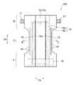
図1及び図2には、本発明の吸収性物品の一実施形態である使い捨ておむつ100(以下、単におむつ100ともいう)の基本的な構造が示されている。
おむつ100は、図1及び図2に示すように、液透過性の表面シート12、液不透過性の裏面シート13、及び両シート12,13間に配置された吸収体14を具備する。裏面シート13に関し、液不透過性とは、液難透過性も含む概念であり、裏面シート13が液を全く通さない場合の他、撥水性のシート等からなる場合等も含まれる。Hereinafter, the present invention will be described based on preferred embodiments with reference to the drawings.
1 and 2 show a basic structure of a disposable diaper 100 (hereinafter, simply referred to as a diaper 100) which is one embodiment of the absorbent article of the present invention.
As shown in FIGS. 1 and 2, the
おむつ100は、着用時に着用者の前後方向と一致する方向である物品長手方向Xaと、おむつ100を、図1に示すように平面状に広げた状態において、物品長手方向Xaと直交する物品幅方向Yaとを有している。また、おむつ100は、物品長手方向Xaに、着用時に着用者の腹側に配される腹側部A、着用時に着用者の背側に配される背側部B、及び腹側部Aと背側部Bとの間に位置する股下部Cに有している。おむつ100は、展開型の使い捨ておむつであり、背側部Bの両側縁部にファスニングテープ17が設けられており、腹側部Aの外表面に、そのファスニングテープ17を止着するランディングゾーン18が設けられている。 The
おむつ100における吸収体14は、吸収性コア14aと該吸収性コア14aを包むコアラップシート14bとを備えている。吸収性コア14aは、例えばパルプ繊維等の吸液性繊維の積繊体や、吸液性繊維と吸水性ポリマーとの混合積繊体から構成することができる。吸液性繊維としては、例えば、パルプ繊維、レーヨン繊維、コットン繊維、酢酸セルロース等のセルロース系の親水性繊維が挙げられる。セルロース系の親水性繊維以外に、ポリオレフィン、ポリエステル、ポリアミド等の合成樹脂からなる繊維を界面活性剤等により親水化したものを用いることもできる。コアラップシート14bとしては、例えば、ティッシュペーパーや透水性の不織布が用いられる。コアラップシート14bは、1枚で吸収性コア14aの全体を包んでいても良いし、2枚以上を組み合わせて吸収性コア14aを包んでいても良い。裏面シート13としては、液不透過性又は撥水性の樹脂フィルム、樹脂フィルムと不織布とのラミネートシート等が用いられる。 The
おむつ100における物品長手方向Xaの両側には、弾性部材15aを有する立体ギャザー形成用のシート15が配されており、その弾性部材15aの収縮により、着用状態における股下部Cに、着用者の肌側に向かって起立する立体ギャザーが形成される。また、股下部Cにおける脚周りに配される部位には、レッグ部弾性部材16が伸長状態で配されており、その収縮により、着用状態における股下部Cに着用者の脚周りへのフィット性を向上させるレッグギャザーが形成される。 On both sides of the
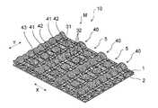
第1実施形態の使い捨ておむつ100における表面シート12は、図3に示す複合シート10から構成されている。
複合シート10は、図3に示すように、おむつ100の長手方向(物品長手方向)Xaに沿う第1方向Xと、おむつ100の幅方向(物品幅方向)Yaに沿う第2方向Yとを有している。また、複合シート10は、図3に示すように、凸部4が相互に異なるパターンで形成された中央領域M及び該中央領域Mの両側に位置する一対のサイド領域S,Sを有している。中央領域Mは、おむつ100の幅方向(物品幅方向)Yaの中央部に位置し、一対のサイド領域S,Sは、中央領域Mの第2方向Yに沿う両側縁の外方に形成されている。相互に異なるパターンで形成された凸部4を有する中央領域M及びその両側の一対のサイド領域S,Sは、おむつ100の長手方向Xaにおいて、少なくとも股下部Cに形成されていることが好ましく、股下部Cから腹側部A及び背側部Bの何れか一方若しくは双方に亘って形成されていること、又は吸収体14の全長に亘っていることが好ましく、更におむつ100の全長に亘っていることが好ましい。The
As shown in FIG. 3, the
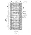
図4には、複合シート10の中央領域Mの一部を拡大して示す斜視図が示されており、図5には、複合シート10のサイド領域Sの一部を拡大して示す斜視図が示されている。サイド領域Sは、おむつ100の長手方向Xaに沿う中央線(図示せず)に対して左右対称の位置に形成されており、各サイド領域Sそれぞれに、図5に示すパターンで凹凸が形成されている。 FIG. 4 is an enlarged perspective view showing a part of a central region M of the
図4及び図5に示すように、複合シート10は、中央領域M及びサイド領域Sの何れにおいても、積層された第1シート1及び第2シート2がエンボス加工により部分的に接合されて複数の接合部が形成され、積層された第1シート及び第2シートが複数の接合部において互いに接合されている。そして、中央領域M及びサイド領域Sの何れにおいても、第1シート1が、前記の接合部以外の部位において第2シート2から離れる方向に突出して、着用者の肌側に向かって突出する凸部を形成している。複合シート10は、中央領域M及びサイド領域Sの何れにおいても、第2シート2側の面がほぼ平坦であり、第1シート1側に起伏の大きな凹凸が形成されている。 As shown in FIGS. 4 and 5, in the
第1シート1及び第2シート2は、シート材料から構成されている。シート材料としては、例えば不織布、織布及び編み地などの繊維シートや、フィルムなどを用いることができ、肌触り等の観点から繊維シートを用いることが好ましく、特に不織布を用いることが好ましい。第1シート1と第2シート2を構成するシート材料の種類は同じでもよく、あるいは異なっていてもよい。 The
第1シート1及び第2シート2を構成するシート材料として不織布を用いる場合の不織布としては、例えば、エアスルー不織布、スパンボンド不織布、スパンレース不織布、メルトブローン不織布、レジンボンド不織布、ニードルパンチ不織布などが挙げられる。これらの不織布を2種以上組み合わせた積層体や、これらの不織布とフィルム等とを組み合わせた積層体を用いることもできる。これらのなかでも、エアスルー不織布又はスパンボンド不織布を用いることが好ましい。第1シート1及び第2シート2を構成するシート材料として用いる不織布の坪量は、好ましくは10g/m2以上、より好ましくは15g/m2以上であり、また好ましくは40g/m2以下、より好ましくは35g/m2以下である。不織布の坪量は10g/m2以上40g/m2以下であることが好ましく、15g/m2以上35g/m2以下であることが更に好ましい。When a nonwoven fabric is used as the sheet material constituting the
不織布を構成する繊維としては、各種の熱可塑性樹脂からなる繊維を用いることができる。熱可塑性樹脂としては、ポリエチレンやポリプロピレンなどのポリオレフィン、ポリエチレンテレフタレートなどのポリエステル、ナイロン6やナイロン66などのポリアミド、ポリアクリル酸、ポリメタクリル酸アルキルエステル、ポリ塩化ビニル、ポリ塩化ビニリデンなどが挙げられる。これらの樹脂は1種を単独で又は2種以上のブレンド物として用いることができる。また、芯鞘型やサイド・バイ・サイド型などの複合繊維の形態で用いることができる。 As the fibers constituting the nonwoven fabric, fibers made of various thermoplastic resins can be used. Examples of the thermoplastic resin include polyolefins such as polyethylene and polypropylene; polyesters such as polyethylene terephthalate; polyamides such as nylon 6 and nylon 66; polyacrylic acid, alkyl methacrylate, polyvinyl chloride, and polyvinylidene chloride. One of these resins can be used alone or as a blend of two or more. Further, it can be used in the form of a composite fiber such as a core-sheath type or a side-by-side type.
複合シート10の中央領域Mには、図4に示されるとおり、第2方向Yに連続して延びる中央連続凸部40が、第1方向Xに一定の距離を隔てて複数本形成されている。複合シート10の中央領域Mには、第1接合部31及び第2接合部32が形成されている。
他方、複合シート10の一対のサイド領域S,Sには、図5に示されるとおり、第1シート1が、第3接合部33以外の部位において第2シート2から離れる方向に突出して形成されたサイド第1凸部41’が、平面視して散点状に形成されており、第1方向X及び第2方向Yのそれぞれに分散した状態に形成されている。
サイド第1凸部41’は、中央領域Mにおける中央連続凸部40や、該中央連続凸部40を構成する中央第1凸部41及び中央第2凸部42とは異なるパターンで形成されている。凸部のパターンが異なるという表現には、凸部の配置のみが異なる場合と、凸部の形態が異なる場合と、それらの両方が異なる場合の何れもが含まれる。凸部の配置が異なる態様には、凸部間の距離が異なる場合も含まれる。また凸部の形態が異なる態様には、凸部の平面視形状が異なる場合も含まれる。
本実施形態の複合シート10においては、中央領域Mと一対のサイド領域S,Sとで、凸部の配置及び形態が異なっている。As shown in FIG. 4, a plurality of central
On the other hand, as shown in FIG. 5, the
The side first
In the
また、サイド領域Sにおける第3接合部33のそれぞれにおいては、第1シート1及び第2シート2の一方又は双方の構成繊維の構成樹脂が溶融固化した状態となっており、また、第3接合部33のそれぞれにおいては、第1シート1及び第2シート2は、何れも他の部分(接合部以外の部分)に比して高密度化している。即ち、複合シート10における第3接合部33は、第1シート1と第2シート2とが一体的に加熱及び加圧されて形成された熱融着部であり、一方又は両方のシートの構成繊維の構成樹脂の溶融及びその後の固化により両シートが互いに結合されている。
また、中央領域Mにおける第1及び第2接合部31,32も同様であり、第1シート1及び第2シート2の一方又は双方の構成繊維の構成樹脂が溶融固化した状態となっており、また、第1及び第2接合部31,32においては、第1シート1及び第2シート2は、何れも他の部分(接合部以外の部分)に比して高密度化している。即ち、複合シート10における第1及び第2接合部31,32も、第1シート1と第2シート2とが一体的に加熱及び加圧されて形成された熱融着部であり、一方又は両方のシートの構成繊維の構成樹脂の溶融及びその後の固化により両シートが互いに結合されている。
なお、第1〜第3接合部31,32及び33のそれぞれにおいては、それぞれ、第1シート1及び第2シート2の両方が溶融固化していることが好ましい。また、中央領域Mにおける第1及び第2接合部31,32については、第1シート1と第2シート2との間が、熱融着以外の接合手段、例えばホットメルト接着剤等の接着剤によって形成されていても良い。In each of the
The same applies to the first and
In each of the first to
また、サイド領域Sにおける第3接合部33は、熱融着部であるとともに、第3接合部33のうちの一部の接合部33aが貫通孔33cを有している。貫通孔33cは、図6に示すように、接合部33aにおいて、複合シート10を厚み方向に貫通している。また、貫通孔33cは、接合部33aの中央部に形成されており、複合シート10の平面視における貫通孔33cの周囲には、第1シート1及び第2シート2の一方又は両方が溶融後固化した部分が環状に存在している。 The third joint 33 in the side region S is a heat-sealed part, and a part of the third joint 33 has a through
第1実施形態のおむつ100によれば、表面シート12を構成する複合シート10が、おむつ100の股下部Cに、凸部のパターンが異なる中央領域M及び一対のサイド領域S,Sを有しており、また、その一対のサイド領域S,Sに形成された第3接合部33の一部が、貫通孔33cを有する接合部33aであるため、股下部cにおける一対のサイド領域S,Sに形成された第3接合部33がすべて貫通孔33cを有しない場合に比べて、一対のサイド領域S,Sが、おむつ100の長手方向(物品長手方向)Xaに沿って折れ曲がり易く、おむつ100の着用時に、複合シート10のサイド領域Sが配されたおむつ100の両側部部分が、着用者の脚回りに沿って曲がり易く、着用者の脚回りに違和感を与えにくい。
また、貫通孔33cを熱融着部である第3接合部33に形成しているため、着用者の左右の大腿部等により、おむつ100の股下部Cにおける両側部に、左右から中央方向への圧縮力が加わったときに、第3接合部33の形状やサイド第1凸部41’の立体形状が比較的安定に維持される。
これにより、第1実施形態のおむつ100は、着用者の脚回りに違和感を与えにくい上に、表面シート12がサイド第1凸部41’の保形性に優れ、通気性にも優れている。なお、本実施形態の複合シート10においては、サイド第1凸部41’の形状、大きさ及び配置が、主として第3接合部33の形状、大きさ及び配置によって決まっている。According to the
In addition, since the through-
Thereby, the
第1実施形態のおむつ100の表面シート12に用いた前記複合シート10について更に説明する。
図7には、図3に示す複合シート10の中央領域Mの拡大平面図が示されている。図8(a)〜図8(c)は、図7のVa−Va線断面図、Vb−Vb線断面図及びVc−Vc線断面図である。
図3、図4及び図7に示されるとおり、複合シート10の中央領域Mには、第2方向Yに連続して延びる中央連続凸部40が、第1方向Xに一定の距離を隔てて複数本形成されている。股下部Cにおける中央領域Mに、物品幅方向Yaに沿う第2方向Yに延びる複数本の中央連続凸部40を、物品長手方向Xaに沿う第1方向Xに複数本配することで、使用中に蒸れやすい排尿部近辺の通気性を向上させることができる。The
FIG. 7 is an enlarged plan view of the central region M of the
As shown in FIGS. 3, 4, and 7, in the central region M of the
第1実施形態で用いた複合シート10においては、中央連続凸部40のそれぞれにおいては、図7及び図8(a)に示すように、第2方向Yに交互に配置された中央第1凸部41と、中央第1凸部41よりも高さの低い中央第2凸部42とが互いに連結されている。本明細書において、凸部が連結されているとは、隣り合う2個の凸部が、接合部によって隔てられておらず、一方の凸部の一部が他方の凸部の一部をなし、かつ他方の凸部の一部が一方の凸部の一部をなしていることをいう。
中央連続凸部40を構成する中央第1凸部41及び中央第2凸部42は、少なくとも中央第1凸部41の裏側に空洞が存在することが好ましく、それぞれの裏側に空洞が存在し、中央第1凸部41の裏面の空洞と中央第2凸部42の裏面の空洞とが連続して、中央連続凸部40の裏側に、第2方向Yに沿って連続して延びる連続中空部40Vが形成されていることが更に好ましい。
中央連続凸部40を構成する中央第1凸部41と中央第2凸部42は、図7に示すように、何れも平面視での形状が略円形状である。また、中央第1凸部41及び第2凸部42は、第1方向X及び第2方向Yの何れの方向での断面においても頂部を有する形状をしている。In the
The central first
As shown in FIG. 7, each of the central first
図7に示すように、複合シート10の中央領域Mには、第2方向Yに延在し、第2方向Yに連続して接合部を有しない非エンボス領域Nと、第2方向Yに延在し、接合部が規則的なパターンで形成されたエンボス領域Eとが、第1方向Xに交互に形成されている。
エンボス領域Eには、積層された第1シート1及び第2シート2が、エンボス加工により部分的に接合されて形成された接合部として、第1接合部31及び第2接合部32が形成されている。As shown in FIG. 7, in the central region M of the
In the emboss region E, a first
個々のエンボス領域Eにおいて、第1接合部31と第2接合部32とは、図7に示すように、第2方向Yにおける配置位置が異なっている。また第1接合部31と第2接合部32とは、第2方向Yに沿う長さL1,L2も異なっている。第1接合部31は何れも平面視形状が矩形であり、その矩形の各辺は第1方向X又は第2方向Yと一致している。第2接合部32は平面視形状が略正方形であり、その正方形の各辺は第1方向X又は第2方向Yと一致している。
矩形をしている第1接合部31は、その長辺を第1方向Xに一致させ、かつ第2方向Yに沿って間隔を置いて一列に配置されている。それによって、第2方向Yに沿う第1接合部列R1が形成されている。第2接合部32は、互いに直交する2辺のうちの一辺を第2方向Y、他の一辺を第1方向Xに一致させ、かつ第2方向Yに沿って間隔を置いて一列に配置されている。それによって第2方向Yに沿う第2接合部列R2が形成されている。
各第1接合部列R1においては、第2方向Yにおける第1接合部31の配置間隔は一定である。各第2接合部列R2においては、第2方向Yにおける第2接合部32の配置間隔は、2種類の間隔で有し、間隔の広い部分と間隔の狭い部分とを交互に有している。各第1接合部列R1においては、第2方向Yに沿って見たときの第1接合部31の配置位置はすべて同じになっている。各第2接合部列R2についても、第2方向Yに沿って見たときの第2接合部32の配置位置はすべて同じになっている。In each of the embossed regions E, the first
The first joining
In each first joint portion row R1, the arrangement interval of the first
個々のエンボス領域Eは、図7に示すように、1つの第1接合部列R1と第1方向Xにおいてその両側に位置する2つの第2接合部列R2とを含んでいる。
第1接合部列R1を構成する1つの第1接合部31に着目すると、2つの第2接合部列R2を構成する合計4つの第2接合部32が、その第1接合部31の周囲に、その第1接合部31の4つの角部にそれぞれの角部を対向させた状態に近接配置されている。それによって、1つの第1接合部31とその周囲に位置する4つの第2接合部32とからなる一纏りの接合部群30が形成されている。個々のエンボス領域Eにおいては、同様の接合部群30が、第2方向Yに沿って一定の間隔で複数形成されている。As shown in FIG. 7, each embossed region E includes one first joint portion row R1 and two second joint portion rows R2 located on both sides thereof in the first direction X.
Focusing on one first
複合シート10においては、第1接合部31及び第2接合部32が上述した態様で形成されていること、及び複合シート10の製造時に、第1シート1における、非エンボス領域Nに相当する部分やエンボス領域Eにおける第1接合部31どうし間の部位に相当する部分を、裏面側から押圧したり、表面側から吸引したりすること等によって、複合シート10の中央領域Mに、図7及び図8に示すような平面視形状及び断面形状の、中央第1凸部41を含む中央連続凸部40や、中央第3凸部43等が形成されている。 In the
第1実施形態に用いた複合シート10の中央領域Mの中央連続凸部40は、第2方向Yに連続して延びるとともに、第2方向Yに規則的に幅が括れた部分を有している。詳細には、図7に示すように、非エンボス領域Nを挟んで対向する一対の第1接合部31どうし間に、中央第1凸部41が形成され、非エンボス領域Nを挟んで対向する二対の第2接合部32からなる合計四個の第2接合部32に囲まれた領域に中央第2凸部42が形成されており、第1方向Xに沿う方向の長さに関し、中央第1凸部41の長さL41よりも中央第2凸部42の長さL42が短くなっている。中央連続凸部40は、その中央第2凸部42からなる部分が、中央第1凸部41からなる部分に比して幅(第1方向Xの長さ)の狭い括れ部分となっている。 The central continuous
第1実施形態に用いた複合シート10は、中央領域Mにおけるエンボス領域E上が、非エンボス領域Nを挟む両側の中央連続凸部40に比して高さの低い溝部5(図4参照)となっており、また、サイド領域Sにおける第1凸部41’間が凹部となっており、より詳細には図10に示す第3方向接合部列R5上及び第4方向接合部列R6上が、溝状の凹部5S(図9参照)となっている。そして、中央領域Mとサイド領域Sとの境界部においては、図9に示すように、中央連続凸部40どうし間の溝部5が、サイド領域Sの凸部間に形成された凹部5Sと連続している。連続するとは、溝部5内の空間と凹部5S内の空間とが複合シート10の平面方向に連通していることを意味する。
これにより、股下部C等における中央領域M上に供給された尿等の液体を、溝部5が導液路になってサイド領域Sに導き、その液体を、サイド領域Sからも吸収体14に吸収させることができ、尿等の排泄物の吸収体14の全域からの均一吸収を促進することができる。中央連続凸部40どうし間の溝部と連続する凹部5Sは、貫通孔33cを有する接合部33a上の空間を含んでいることが液の吸収性が上がってモレが防止される点から好ましい。In the
Thereby, the liquid such as urine supplied on the central region M in the crotch C and the like is guided to the side region S by the
また、第1実施形態に用いた複合シート10は、図7及び図8(c)に示すように、エンボス領域E内に、周囲を環状凹部で囲まれた非連続の中央第3凸部43を有している。中央第3凸部43は、第1方向X及び第2方向Yの何れの方向での断面においても頂部を有する形状をしている。中央第3凸部43は、高さが中央第1凸部41より低い。中央第3凸部43は、それぞれの裏側に空洞43Vを有しているが、そのような空洞43Vを有しないものであっても良い。 As shown in FIGS. 7 and 8C, the
中央第3凸部43は、図7に示すとおり、その複数個が、第2方向Yに沿って一定の距離を隔てて直線的に列状に配置されて、中央第3凸部列を構成している。中央第2凸部42も、その複数個が、第2方向Yに沿って一定の距離を隔てて直線的に列状に配置されて、中央第2凸部列を構成している。中央第2凸部42と中央第3凸部43とは、第2方向Yにおける同じ位置に形成されている。より詳細には、中央第2凸部42と中央第3凸部43とが、第1方向Xに沿って交互に、かつ直線状に配置されている。中央第3凸部43は、第1方向Xにおける配置位置が、中央第1凸部41,41どうし間に位置している。第1方向Xにおける配置位置とは、第2方向Yの位置を無視して、第1方向Xにおける位置のみを視たときの配置位置である。更に、図7に示すように、中央第2凸部42及び中央第3凸部43に加えて第4凸部44にも着目すると、これら3種類の凸部は、中央第2凸部42と第4凸部44と中央第3凸部43と第4凸部44とがこの順で、第1方向Xに沿って規則的に、かつ直線状に配置されている。
第4凸部44は、その上面が概ね平坦になっている。なお、第4凸部44は文字どおり「凸部」ではあるが、該第4凸部44は、中央連続凸部40を構成する中央第1及び第2凸部41,42の何れよりも相対的に高さが低く、かつ中央第3凸部43よりも相対的に高さが低いことから、これらの凸部から見て相対的に凹部となる。As shown in FIG. 7, a plurality of central third
The upper surface of the fourth
本実施形態に用いた複合シート10の中央領域Mは、これを構成する第1シート1に、前述した中央第1凸部41、中央第2凸部42、中央第3凸部43及び第4凸部44が形成されている。第4凸部44は、中央第1凸部41、中央第2凸部42及び中央第3凸部43の何れよりも高さが低くなっている。 The central region M of the
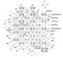
図10には、図3に示す複合シート10のサイド領域Sの拡大平面図が示されている。図11は、図10におけるVd−Vd線断面図である。図6は、図10におけるVe−Ve線断面図である。
これらの図に示されるとおり、複合シート10のサイド領域Sは、複数の第3接合部33が第1方向Xに直列した第1方向接合部列Rxを第2方向Yに複数列有しており、複数の第3接合部33が第2方向Yに直列した第2方向接合部列Ryを第1方向Xに複数列有している。FIG. 10 shows an enlarged plan view of the side region S of the
As shown in these drawings, the side region S of the
複合シート10のサイド領域Sには、第3接合部33が第1方向Xに沿って等間隔に配置された第1方向接合部列Rxが、第2方向Yに複数列形成されている。第2方向Yに複数列形成されている第1方向接合部列Rxは、第1方向Xにおける第3接合部33の配置位置が一致する隣り合う2列と、その2列とは、第1方向Xにおける第3接合部33の配置位置が異なる他の隣り合う2列とを、第2方向Yに交互に有している。
複合シート10のサイド領域Sには、第3接合部33が第2方向Yに沿って2種類の間隔La,Lbで規則的に配置された第2方向接合部列Ryが、第1方向Xに複数列形成されている。より詳細には、第2方向接合部列Ryは、第2方向Yにおける第3接合部33どうし間の間隔として、第1の間隔Laと、第1の間隔Laよりも広い第2の間隔Lbとを有しており、第2方向接合部列Ry中の複数の第3接合部33は、これら2種類の間隔を、第2方向Yに交互に有するように第2方向Yに間欠配置されている。In the side area S of the
In the side region S of the
個々の第2方向接合部列Ryを構成する複数の第3接合部33は、第1方向Xにおける長さ及び配置位置が一致しており、第1方向Xにおいて隣り合う第2方向接合部列Ry間には一定の幅Wの隙間が形成されている。また、第1方向Xに複数列形成されている第2方向接合部列Ryは、一列置きに、第2方向Yにおける第3接合部33の配置位置が一致しており、隣り合う第2方向接合部列Rどうしは、第2方向Yにおける第3接合部33の配置位置が相互に異なる。詳細には、本実施形態における複合シート10のサイド領域Sには、図10に示すように、第2方向接合部列Ryとして、第2方向Yにおける第3接合部33の配置位置が相互に異なる第2方向第1接合部列Ry1と第2方向第2接合部列Ry2とが、第1方向Xに交互に形成されており、第2方向Yにおける第3接合部33の配置位置に関しては、第2方向第1接合部列Ry1及び第2方向第2接合部列Ry2は、一方における第2の間隔Lbで隣り合う第3接合部33どうし間に、他方の接合部列Rにおける第1の間隔Laで隣り合う一対の第3接合部33が位置している。 The plurality of
そして、図10に示すように、第2方向接合部列R中において隣り合う2つの第3接合部33,33を含む合計6個の接合部33に囲まれた領域内に、前述したサイド第1凸部41’が形成されている。 Then, as shown in FIG. 10, in the region surrounded by a total of six
本実施形態の複合シート10においては、個々の第2方向接合部列Rに、第2方向Yに第1の間隔Laで近接配置された一対の第3接合部33からなる接合部対34が、第2方向Yに第1の間隔Laの2倍以上の間隔Lbで間欠配置されており、サイド第1凸部41’は、第2方向Yにおいて隣り合う接合部対34,34どうし間に形成されている。接合部対34は、第2方向接合部列R中において最も狭い間隔Laで隣り合う一対の第3接合部33からなる。 In the
複合シート10においては、第3接合部33が上述した態様で形成されていること、及び複合シート10の製造時に、第1シート1における、合計6個の第3接合部33に囲まれた領域に相当する部分を、裏面側から押圧したり、表面側から吸引したりすること等によって、複合シート10のサイド領域Sに、図10及び図11に示すような平面視形状及び断面形状のサイド第1凸部41’が多数形成されている。
In the
第1実施形態における複合シート10のサイド領域Sは、図10に示すように、前述した第1方向接合部列Rxと前述した第2方向接合部列Ryのうちの、第2方向接合部列Ryが、貫通孔33cを有する接合部33aの割合が最も高い最大割合接合部列Rymを含んでいる。
第2方向接合部列Ryが最大割合接合部列Rymを含むことで、おむつ100の幅方向(物品幅方向)に沿って折れ曲がり易く、おむつ100の着用時に、複合シート10のサイド領域Sが配されたおむつ100の両側部部分が、着用者の脚回りの湾曲形状に沿って曲がり易く脚回りへのフィット感が向上し、着用者の脚回りに違和感を与えにくい。As shown in FIG. 10, the side region S of the
Since the second direction joint row Ry includes the maximum ratio joint row Rym, it is easy to bend along the width direction (article width direction) of the
ここで、「最大割合接合部列」は、おむつ1枚の各サイド領域Sから任意に2枚ずつ切り出した第1方向の長さ20mm、第2方向の長さ100mm矩形状の測定片を観察して、以下の手順(1)〜(3)で決定する。
(1)第1方向接合部列Rxのなかから、貫通孔33cを有する接合部33aの割合が最も高い接合部列を選択して、その接合部列を第1方向最大割合接合部列Rxmとする。例えば、図10に示すように、第1方向接合部列Rxとして、貫通孔を有しない第3接合部33と貫通孔33cを有する第3接合部33aとを第1方向Xに交互に有し、その接合部列を構成する接合部の個数のうちの貫通孔33cを有する接合部33aの割合(以下、「孔付接合部割合」ともいう)が50%である第1方向第1接合部列Rx1と、その接合部列を構成する接合部の個数のうちの全てが貫通孔33cを有しない接合部33であって、前記孔付接合部割合が0%である第1方向第2接合部列Rx2とを有する場合、前記孔付接合部割合が最も高い第1方向第1接合部列Rx1が、第1方向最大割合接合部列Rxmとなる。
(2)第2方向接合部列Ryのなかから、貫通孔33cを有する接合部33aの割合が最も高い接合部列を選択して、その接合部列を第2方向最大割合接合部列Rymとする。例えば、図10に示すように、第2方向接合部列Ryとして、接合部列を構成する接合部の個数のうちの全てが貫通孔33cを有する接合部33aであり、孔付接合部割合が100%である第1の第2方向第1接合部列Ry1と、接合部列を構成する接合部の個数のうちの全てが貫通孔33cを有しない接合部33であり、前記孔付接合部割合が0%である、第2の第2方向第1接合部列Ry1及び第2方向第2接合部列Ry2とを有する場合、前記孔付接合部割合が最も高い第1の第2方向第1接合部列Ry1が、第2方向最大割合接合部列Rymとなる。図10に示す例においては、第1方向Xに3列置きに配された第1の第2方向第1接合部列Ry1が、第2方向最大割合接合部列Rymである。
(3)第1方向最大割合接合部列Rxmの孔付接合部割合と、第2方向最大割合接合部列Rymの孔付接合部割合とを比較し、孔付接合部割合がより高い方を、最大割合接合部列とする。図10に示す例では、第1方向最大割合接合部列Rxmの孔付接合部割合が50%であるのに対し、第2方向最大割合接合部列Rymの孔付接合部割合が100%であるため、孔付接合部割合が100%である、第2方向最大割合接合部列Rymが最大割合接合部列となる。Here, the "maximum ratio joint portion row" is a rectangular diaper that has a length in the first direction of 20 mm and a length in the second direction of 100 mm, which are arbitrarily cut out from each side region S of one diaper. Then, it is determined in the following procedures (1) to (3).
(1) From among the first direction joining portion rows Rx, a joining portion row having the highest ratio of the joining
(2) From the second direction joint row Ry, a joint row having the highest ratio of the joint 33a having the through
(3) The ratio of the joints with holes in the first direction maximum ratio joint row Rxm is compared with the ratio of the joints with holes in the second direction maximum ratio joint row Rym, and the higher the ratio of the joints with holes is higher. , The maximum ratio of the joint rows. In the example illustrated in FIG. 10, the joint ratio with holes in the first proportion joint row Rxm in the first direction is 50%, while the joint proportion with holes in the joint row Rym in second direction is 100%. For this reason, the maximum ratio joint row Rym in the second direction, in which the joint ratio with holes is 100%, is the maximum ratio joint row.
また、第1実施形態における複合シート10のサイド領域Sは、図10に示すように、第1方向Xに複数列有する第2方向接合部列Ryのうち、貫通孔33cを有する接合部33aの割合(前記孔付接合部割合)が最も高い第2方向最大割合接合部列Rymを第1方向Xに周期的に有している。
第2方向最大割合接合部列Rymを第1方向Xに周期的に有すると、おむつ100の幅方向(物品幅方向)に沿って規則的に折れ曲がり易く、おむつ100の着用時に、複合シート10のサイド領域Sが配されたおむつ100の両側部部分が、着用者の脚回りの湾曲形状に沿ってフィット感が更に向上し、着用者の脚回りにさらに違和感を与えにくい。
「第2方向最大割合接合部列」は、上記の手順(2)に記載の方法で決定する。Further, as shown in FIG. 10, the side region S of the
When the second direction maximum ratio joint row Rym is periodically provided in the first direction X, the
The “maximum ratio joint portion row in the second direction” is determined by the method described in the above procedure (2).
図10に示す例においては、第2方向最大割合接合部列Rymが、第1方向Xにおいて、3列置きに配されているが、1列置き、2列置き、又は4列置きに配されていても良い。また、孔付接合部割合が100%及び0%の第2方向接合部列に加えて、孔付接合部割合がそれらの0%超100%未満の第2方向接合部列を有していても良い。
なお、第2方向最大割合接合部列Rymは、孔付接合部割合が、好ましくは10%以上100%以下であり、より好ましくは15%以上100%以下である。また、第2方向最大割合接合部列Rymは、第2方向接合部列Ryのうち、孔付接合部割合が最低の接合部列Ryとの差が、好ましくは5%ポイント以上、より好ましくは10%ポイント以上、また好ましくは100%ポイント以下、より好ましくは95%ポイント以下である。
また、第1方向最大割合接合部列Rxmは、孔付接合部割合が、好ましくは10%以上100%以下であり、より好ましくは15%以上95%以下である。また、第1方向最大割合接合部列Rxmは、第1方向接合部列Rxのうち、孔付接合部割合が最低の接合部列Rxとの差が、好ましくは0%ポイント以上、より好ましくは5%ポイント以上、また好ましくは95%ポイント以下、より好ましくは90%ポイント以下である。
また、第2方向最大割合接合部列Rymと第1方向最大割合接合部列Rxmは、孔付接合部割合の差が、好ましくは5%ポイント以上、より好ましくは10%ポイント以上、また好ましくは90%ポイント以下、より好ましくは80%ポイント以下である。In the example shown in FIG. 10, the maximum proportion joint rows Rym in the second direction are arranged every three rows in the first direction X, but are arranged every other row, every two rows, or every four rows. May be. In addition, in addition to the second direction joint row having the hole-bonded joint ratio of 100% and 0%, the second direction joint row having the hole-bonded joint ratio of more than 0% and less than 100% is provided. Is also good.
In the second direction maximum ratio bonding portion row Rym, the bonding portion ratio with holes is preferably 10% or more and 100% or less, and more preferably 15% or more and 100% or less. In the second direction maximum ratio joint row Rym, the difference between the second direction maximum joint row Ry and the joint row Ry having the lowest holed joint ratio is preferably 5% or more, more preferably. It is 10% or more, preferably 100% or less, more preferably 95% or less.
Further, in the first direction maximum proportion joint row Rxm, the joint proportion with holes is preferably 10% or more and 100% or less, more preferably 15% or more and 95% or less. In the first direction maximum ratio joint portion row Rxm, the difference between the first direction joint portion row Rx and the joint portion row Rx having the lowest joint portion ratio with holes is preferably 0% point or more, and more preferably. It is 5% or more, preferably 95% or less, more preferably 90% or less.
In the second direction maximum ratio joint row Rym and the first direction maximum ratio joint row Rxm, the difference in the joint ratio with holes is preferably 5% or more, more preferably 10% or more, and more preferably It is 90% or less, more preferably 80% or less.
また、複合シート10のサイド領域Sは、サイド領域Sに含まれる接合部33のうち、貫通孔33cを有する接合部33aの割合が、おむつ100等の吸収性物品を柔らかくしつつ、応力によるサイド第1凸部41’の立体形状の変形を抑制する観点から、好ましくは5%以上、より好ましくは10%以上、更に好ましくは15%以上であり、また好ましくは80%以下、より好ましくは75%以下、更に好ましくは70%以下である。
ここでいう、「割合(%)」は、サイド領域Sから2枚ずつ切り出した第1方向Xの長さ20mm、第2方向Yの長さ100mm矩形状の測定片に含まれる、貫通孔33cを有する接合部33aの個数を、該測定片に含まれる接合部の全数で除した数値を100倍して求められる。またこれは、4サンプルの平均値とする。In the side region S of the
Here, the “ratio (%)” refers to the through
第1実施形態における複合シート10のサイド領域Sの構成について更に説明する。
図3、図5及び図10に示されるとおり、複合シート10のサイド領域Sには、サイド第1凸部41’が、複合シート10に、平面視散点状、より詳細には千鳥状に形成されている。サイド第1凸部41’は、前述した6個の第3接合部33によって囲まれている。サイド第1凸部41’を囲む6個の第3接合部33及び6個の第3接合部33における互いに隣り合う第3接合部33間の部位は、サイド第1凸部41’の中央部の周囲に環状の凹部を形成しており、サイド第1凸部41’は、複合シート10の平面方向に分散した状態に形成されている。
より詳細には、図10に示すように、平面視した複合シート10に、互いに平行な複数本の第1の仮想直線L3と、第1仮想直線L3との間に角度θ(図10参照)を有する互いに平行な複数本の第2の仮想直線L4とを想定したときに、第1仮想直線L3と第2仮想直線L4との各交点に、サイド第1凸部41’が位置している。
サイド第1凸部41’を格子の交点に配置することで、股下部C等における中央領域M上に供給された液体は、第2方向Yに沿って配置された溝部5が導液路になってサイド領域Sに導かれ、サイド領域Sに格子状に配置されたサイド第1凸部41’が障壁となり第1方向Xへの拡散も促進し、尿等の排泄物の吸収体14の全域からの均一吸収をさらに促進することができる。
第1の仮想直線L3と第2の仮想直線L4とのなす角度θ(図10参照)は、30°以上165°以下が好ましく、45°以上150°以下が更に好ましい。なお、図10に示す例においては、第1の仮想直線L3及び第2の仮想直線L4は、いずれも、第1方向X及び第2方向Yに対して傾斜しているが、第1の仮想直線L3又は第2の仮想直線L4の何れか一方又は双方を、第1方向X又は第2方向Yと平行としても良い。The configuration of the side region S of the
As shown in FIGS. 3, 5, and 10, in the side region S of the
More specifically, as shown in FIG. 10, an angle θ is formed between a plurality of first virtual straight lines L3 parallel to each other and the first virtual straight line L3 on the
By arranging the side first
The angle θ between the first virtual straight line L3 and the second virtual straight line L4 (see FIG. 10) is preferably 30 ° or more and 165 ° or less, and more preferably 45 ° or more and 150 ° or less. In the example shown in FIG. 10, the first virtual straight line L3 and the second virtual straight line L4 are both inclined with respect to the first direction X and the second direction Y, One or both of the straight line L3 and the second virtual straight line L4 may be parallel to the first direction X or the second direction Y.
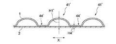
複合シート10のサイド領域Sにおいては、複数のサイド第1凸部41’が、一定の間隔で、第1の仮想直線L3に沿って直列した複数本の第3方向凸部列と、複数のサイド第1凸部41’が、一定の間隔で、第2の仮想直線L4に沿って直列した複数本の第4方向凸部列とが形成されている。また、隣り合う第3方向凸部列どうし間には、複数の接合部対34が、一定の間隔で直列した第3方向接合部列R5が形成され、隣り合う第4方向凸部列どうし間には、複数の接合部対34が、一定の間隔で直列した第4方向接合部列R6が形成されている。個々の接合部対34を構成する一対の第3接合部間及びサイド第1凸部41’の周囲において互いに隣り合う接合部対34どうし間は、微小凸部44’となっているが、微小凸部44’は、第3接合部33の上面より僅かに突出する程度の高さであり、通常、その高さH4’は、サイド第1凸部41’の1/3以下である。
そのため、第3方向凸部列どうし間及び第4方向凸部列どうし間は、空気が流通し易い通気路となり、優れた通気性が得られる。In the side region S of the
Therefore, between the third-direction convex portion rows and the fourth-direction convex portion rows, an air passage through which air easily flows is provided, and excellent air permeability is obtained.
上述した一又は二以上の効果が一層確実に奏されるようにする観点から、複合シートの凸部は、以下の構成を有することが好ましい。
また中央領域Mに形成する高さが最大の凸部である、中央連続凸部40又は該中央連続凸部40の高さが最も高い部分を構成する中央第1凸部41の高さH1〔図8(a)参照〕は、好ましくは0.5mm以上、更に好ましくは1.0mm以上であり、また好ましくは5.0mm以下、更に好ましくは4.0mm以下であり、また好ましくは0.5mm以上5.0mm以下、更に好ましくは1.0mm以上4.0mm以下である。
またサイド領域Sに形成する高さが最大の凸部であるサイド第1凸部41’の高さH1’は、好ましくは0.3mm以上、更に好ましくは0.6mm以上であり、また好ましくは4.0mm以下、更に好ましくは3.0mm以下であり、また好ましくは0.3mm以上4.0mm以下、更に好ましくは0.6mm以上3.0mm以下である。From the viewpoint of more reliably achieving one or more of the effects described above, it is preferable that the protrusions of the composite sheet have the following configuration.
Also, the height H1 of the central continuous
The height H1 'of the side first convex portion 41', which is the largest convex portion formed in the side region S, is preferably 0.3 mm or more, more preferably 0.6 mm or more, and preferably It is 4.0 mm or less, more preferably 3.0 mm or less, preferably 0.3 mm or more and 4.0 mm or less, more preferably 0.6 mm or more and 3.0 mm or less.
複合シートの凸部4に関し、高さとは、吸収体14側に向けられる下面から凸部4の頂部までの高さである。 Regarding the
また、第1接合部31は、第1方向Xに沿う長さが、第2方向Yに沿う長さの、1.2倍以上、特に1.5倍以上であることが好ましく、また5.0倍以下、特に3.0倍以下であることが好ましく、より具体的には、1.2倍以上5.0倍以下、特に1.5倍以上3.0倍以下であることが好ましい。
また、第1接合部31は、第1方向Xに沿う長さが、第2接合部32の第1方向Xに沿う長さの、1.2倍以上、特に1.5倍以上であることが好ましく、また5.0倍以下、特に3.0倍以下であることが好ましく、より具体的には、1.2倍以上5.0倍以下、特に1.5倍以上3.0倍以下であることが好ましい。In addition, the length of the first
Further, the length of the first joining
第1接合部31の第1方向Xに沿う長さは0.5mm以上、特に1.0mm以上であることが好ましく、また10.0mm以下、特に5.0mm以下であることが好ましく、より具体的には、0.5mm以上10.0mm以下、特に1.0mm以上5.0mm以下であることが好ましい。
また第2接合部32は、第1方向Xに沿う長さが、0.1mm以上5.0mm以下、特に0.2mm以上3.0mm以下であることが好ましく、第2方向Yに沿う長さが、0.1mm以上5.0mm以下、特に0.5mm以上3.0mm以下であることが好ましい。
また、第3接合部33は、第1方向Xに沿う長さが、1.2mm以上5.0mm以下、特に1.5mm以上3.0mm以下であることが好ましく、第2方向Yに沿う長さが、1.2mm以上5.0mm以下、特に1.5mm以上3.0mm以下であることが好ましい。
また、第3接合部33についての第2方向接合部列Rは、第2方向Yにおける第3接合部33間の間隔が大きい部分の間隔Laが、間隔が狭い部分の第3接合部33間の間隔に対して、2.0倍以上、特に2.5倍以上であることが好ましく、5.0倍以下、特に4.0倍以下であることが好ましく、2.0倍以上5.0倍以下、特に2.5倍以上4.0倍以下であることが好ましい。The length of the first
Further, the length of the second joining
Further, the third joining
In the second direction joining portion row R for the third joining
各凸部41,41’,42,43,46の高さH1,H1’,H2,H3,H4は、図8及び図11に示すとおり、第2シート2の下面から、第1シート1の上面までの距離と定義される。また高さH1,H1’,H2,H3,H4は、デジタルマイクロスコープ(Keyence製)を用いて各凸部断面を観察し、第2シート2の下面と凸部頂部との最短距離を計測して得られた値とする。 The heights H1, H1 ', H2, H3, and H4 of the
前述した構成の複合シート10を製造するには、特開2015−112343号公報に記載の方法と同様にして、帯状の第1シート1を、周面が互いに噛み合い形状となっている第1ロールと第2ロールとの間に供給して、第1シート1を凹凸形状に変形させた後、第1シート1を第1ロールの周面部に沿わせて噛み合い部分から移動させた後、第2シート2を第1シート1に重ね合わせるように供給して両シート1,2を、第1ロールにおける凸部とヒートロールとの間で加熱下に挟圧して部分的に接合させる。そして、その際、第1シートの中央部と側部とで、第1ロール及び第2ロールの凹凸形状、及び第1ロールとヒートロールで形成する接合部のパターンを異ならせる。また、第1ロール又はヒートロールの周方向又は軸方向の一部を、カートリッジヒーター等の加熱手段により、他の部分よりも高温に加熱し、その加熱により高温とされた部分で挟圧した部分に、貫通孔を有する接合部が形成されるようにする。
第1ロール又はヒートロールの周方向又は軸長方向の一部を他の部分より高温にする方法に代えて、第1ロールにおける凸部の先端に更に突出するピンを設け、該ピンに強く加圧された部分に、接合部の貫通孔が形成されるようにしても良い。なお、第1ロールと第2ロールとの噛み合い部に噛み込ませて第1シート1を凹凸形状に変形させる際には、第1シートをロール内部方向に向けて吸引して、第1シート1の凹凸形状への変形を促進させることが好ましい。In order to manufacture the
Instead of a method in which a part of the first roll or the heat roll in the circumferential direction or the axial direction is heated to a higher temperature than the other part, a protruding pin is further provided at the tip of the convex part of the first roll, and the pin is strongly applied. A through hole of the joint may be formed in the pressed portion. Note that, when the
以上、本発明をその好ましい実施形態に基づき説明したが、本発明は前記実施形態に制限されない。例えば、吸収性物品の表面シートとして、前述した複合シート10の中央領域Mにおける縦長の第1接合部31及び第2接合部32は、第2方向Yにおける幅を同一として、第2方向Yに間隔を開けて交互に且つ等間隔に配置しても良い。中央連続凸部40は、第2方向Yの全長に亘って高さが一定であっても良い。また、中央領域Mの凸部は、散点状に形成されていても良い。また、貫通孔33cの平面視形状は、円形に代えて、楕円形、長円形、三角形、四角形、五角形、六角形、星形、ハート形、三角形等、任意の形状を採用し得る。また、一つの接合部33aの2個以上の貫通孔が形成されていても良いが、個々の接合部に形成する貫通孔は、好ましくは1個以上30個以下である。
また、本発明の吸収性物品は、展開型の使い捨ておむつに代えて、パンツ型(プルオンタイプ)の使い捨ておむつであっても良く、また、パンツ型又は通常の非パンツ型の生理用ナプキンであっても良く、失禁パッド、パンティライナー等であっても良い。Although the present invention has been described based on the preferred embodiments, the present invention is not limited to the above embodiments. For example, as the top sheet of the absorbent article, the vertically long first
Further, the absorbent article of the present invention may be a pants-type (pull-on type) disposable diaper, instead of a deployable disposable diaper, or a pants-type or ordinary non-pants-type sanitary napkin. Or an incontinence pad, panty liner, or the like.
上述した実施形態に関し、本発明は更に以下の吸収性物品を開示する。
<1>
複合シートからなる表面シート、裏面シート及びこれら両シート間に配置された吸収体を具備する吸収性物品であって、前記複合シートは、物品長手方向に沿う第1方向及び物品幅方向に沿う第2方向を有するとともに、積層された第1シート及び第2シートが複数の接合部において互いに接合されており、且つ前記第1シートが、前記接合部以外の部位において前記第2シートから離れる方向に突出して、着用者の肌側に向かって突出した凸部を形成しており、前記複合シートは、前記凸部が相互に異なるパターンで形成された中央領域及び該中央領域の両側に位置する一対のサイド領域を有しており、前記サイド領域Sにおける前記接合部においては、前記第1シート及び前記第2シートの一方又は双方の構成繊維を構成する合成樹脂が溶融固化した状態となっており、該サイド領域Sにおける前記接合部の全部又は一部が貫通孔を有している、吸収性物品。With respect to the above-described embodiment, the present invention further discloses the following absorbent articles.
<1>
An absorbent article comprising a top sheet, a back sheet, and an absorber disposed between these two sheets, wherein the composite sheet has a first direction along an article longitudinal direction and a first direction along an article width direction. While having two directions, the laminated first sheet and second sheet are joined to each other at a plurality of joints, and the first sheet is separated from the second sheet at a portion other than the joints. The composite sheet is protruded to form a convex portion protruding toward the skin side of the wearer, and the composite sheet has a central region in which the convex portions are formed in different patterns from each other and a pair of the convex regions located on both sides of the central region. And the synthetic resin constituting the constituent fibers of one or both of the first sheet and the second sheet is provided at the joint in the side area S. Has a melting solidified state, all or part of the joint portions in the side area S has a through-hole, the absorbent article.
<2>
前記中央領域には、前記第2方向に延びる中央連続凸部が前記第1方向に間隔を開けて複数本形成されている、前記<1>に記載の吸収性物品。
<3>
前記中央領域と前記サイド領域との境界部においては、前記中央連続凸部どうし間の溝部が、該サイド領域の凸部間に形成された凹部と連続している、前記<1>又は<2>に記載の吸収性物品。
<4>
前記サイド領域における前記凸部は、該サイド領域における前記複合シートに、互いに平行な複数本の第1仮想直線と、該第1仮想直線との間に角度を有する互いに平行な複数本の第2仮想直線とを想定したときに、前記第1仮想直線と前記第2仮想直線との各交点に位置している、前記<1>〜<3>の何れか1に記載の吸収性物品。<2>
The absorbent article according to <1>, wherein a plurality of central continuous protrusions extending in the second direction are formed in the center region at intervals in the first direction.
<3>
In the boundary portion between the central region and the side region, the groove between the central continuous convex portions is continuous with the concave portion formed between the convex portions of the side region, wherein <1> or <2> The absorbent article according to <1>.
<4>
The convex portion in the side region includes a plurality of first virtual straight lines parallel to each other and a plurality of second parallel straight lines having an angle between the first virtual straight line and the composite sheet in the side region. The absorbent article according to any one of <1> to <3>, which is located at each intersection of the first virtual straight line and the second virtual straight line when a virtual straight line is assumed.
<5>
前記サイド領域は、複数の前記接合部が前記第1方向に直列した第1方向接合部列を前記第2方向に複数列有し、複数の前記接合部が前記第2方向に直列した第2方向接合部列を前記第1方向に複数列有しており、第2方向接合部列が、前記貫通孔を有する接合部の割合が最も高い最大割合接合部列を含んでいる、前記<1>〜<4>の何れか1に記載の吸収性物品。
<6>
前記サイド領域は、複数の前記接合部が前記第2方向に直列した第2方向接合部列を前記第1方向に複数列有しており、該サイド領域は、第2方向接合部列のうち前記貫通孔を有する接合部の割合が最も高い第2方向最大割合接合部列を前記第1方向に周期的に有している、前記<1>〜<5>の何れか1に記載の吸収性物品。
<7>
前記サイド領域は、前記接合部のうち、前記貫通孔を有する接合部の割合が5%以上80%以下である、前記<1>〜<6>の何れか1に記載の吸収性物品。
<8>
前記中央領域と一対の前記サイド領域とで、前記凸部の配置及び形態が異なっている、前記<1>〜<7>の何れか1に記載の吸収性物品。
<9>
前記中央領域における第1及び第2接合部、前記サイド領域における第3接合部のそれぞれにおいては、それぞれ、第1シート及び第2シートの両方が溶融固化していることが好ましい、前記<1>〜<8>の何れか1に記載の吸収性物品。<5>
The side region includes a plurality of rows in the second direction in which the plurality of joints are arranged in the second direction in a first direction in which the plurality of joints are arranged in the first direction, and a plurality of joints in which the plurality of joints are arranged in the second direction. A plurality of directional joint rows in the first direction, wherein the second directional joint row includes a maximum ratio joint row having the highest proportion of joints having the through holes. > The absorbent article according to any one of <4>.
<6>
The side region includes a plurality of second direction joining portion rows in which the plurality of joining portions are arranged in series in the second direction in the first direction, and the side region includes a second direction joining portion row. The absorption according to any one of <1> to <5>, wherein the bonding portion having the through-hole has the highest ratio of second-direction maximum ratio bonding portion rows in the first direction periodically. Products.
<7>
The absorbent article according to any one of <1> to <6>, wherein, in the side region, a ratio of the joint having the through hole to the joint is 5% or more and 80% or less.
<8>
The absorbent article according to any one of <1> to <7>, wherein the central region and the pair of side regions have different arrangements and forms of the protrusions.
<9>
In each of the first and second joints in the central region and the third joint in the side region, it is preferable that both the first sheet and the second sheet are melted and solidified, respectively. <1> -The absorbent article according to any one of <8>.
<10>
前記貫通孔は、前記第3接合部のうちの一部の接合部の中央部に形成されており、前記複合シートの平面視における前記貫通孔の周囲には、前記第1シート及び前記第2シートの一方又は両方が溶融後固化した部分が環状に存在している、前記<1>〜<9>の何れか1に記載の吸収性物品。
<11>
前記中央領域で前記第2方向に延びる中央連続凸部のそれぞれにおいては、前記第2方向に交互に配置された中央第1凸部と、該中央第1凸部よりも高さの低い中央第2凸部とが互いに連結されている、前記<1>〜<10>の何れか1に記載の吸収性物品。
<12>
前記中央領域で前記第2方向に延びる中央連続凸部を構成する中央第1凸部及び中央第2凸部は、少なくとも前記中央第1凸部の裏側に空洞が存在することが好ましい、前記<1>〜<11>の何れか1に記載の吸収性物品。
<13>
前記中央領域で、前記第2方向に延びる中央連続凸部を構成する中央第1凸部及び中央第2凸部は、それぞれの裏側に空洞が存在し、前記中央第1凸部の裏面の空洞と前記第2凸部の裏面の空洞とが連続して、前記中央連続凸部の裏側に、前記第2方向に沿って連続して延びる連続中空部が形成されている、前記<1>〜<12>の何れか1に記載の吸収性物品。
<14>
前記複合シートの前記中央領域には、前記第2方向に延在し、該第2方向に連続して前記接合部を有しない非エンボス領域と、前記第2方向に延在し、前記接合部が規則的なパターンで形成されたエンボス領域とが、前記第1方向に交互に形成されている、前記<1>〜<13>の何れか1に記載の吸収性物品。<10>
The through-hole is formed at a central portion of a part of the third joint, and the first sheet and the second sheet are formed around the through-hole in plan view of the composite sheet. The absorbent article according to any one of the above <1> to <9>, wherein a portion where one or both of the sheets is solidified after melting exists in a ring shape.
<11>
In each of the central continuous convex portions extending in the second direction in the central region, a central first convex portion alternately arranged in the second direction and a central first convex portion having a lower height than the central first convex portion. The absorbent article according to any one of <1> to <10>, wherein the two convex portions are connected to each other.
<12>
The central first convex portion and the central second convex portion constituting the central continuous convex portion extending in the second direction in the central region preferably have a cavity at least on the back side of the central first convex portion. The absorbent article according to any one of 1> to <11>.
<13>
In the central region, the central first convex portion and the central second convex portion constituting the central continuous convex portion extending in the second direction have cavities on the back sides thereof, and cavities on the back surface of the central first convex portion. And a cavity on the back surface of the second convex portion is continuous, and a continuous hollow portion extending continuously along the second direction is formed on the back side of the central continuous convex portion. The absorbent article according to any one of <12>.
<14>
A non-embossed region extending in the second direction and continuously having no joint in the second direction, and a non-embossed region extending in the second direction in the central region of the composite sheet; The absorbent article according to any one of <1> to <13>, wherein embossed regions formed in a regular pattern are alternately formed in the first direction.
<15>
前記第2方向に延在し、前記接合部が規則的なパターンで形成された個々のエンボス領域において、前記中央領域における第1接合部と第2接合部とは、前記第2方向における配置位置が異なっており、前記第1接合部と前記第2接合部とは、前記第2方向に沿う長さL1,L2も異なっている、前記<1>〜<14>の何れか1に記載の吸収性物品。
<16>
前記中央領域で矩形をしている第1接合部は、その長辺を前記第1方向に一致させ、かつ前記第2方向に沿って間隔を置いて一列に配置されており、それによって、前記第2方向に沿う第1接合部列が形成されている、前記<1>〜<15>の何れか1に記載の吸収性物品。
<17>
前記中央領域で四角形状の第2接合部は、互いに直交する2辺のうちの一辺を前記第2方向、他の一辺を前記第1方向に一致させ、かつ前記第2方向に沿って間隔を置いて一列に配置されており、それによって、前記第2方向に沿う第2接合部列が形成されている、前記<1>〜<16>の何れか1に記載の吸収性物品。
<18>
前記中央領域の矩形をしている第1接合部は、その長辺を前記第1方向に一致させ、かつ前記第2方向に沿って間隔を置いて一列に配置され、それによって、前記第2方向に沿う第1接合部列が形成されており、
前記第1接合部列においては、前記第2方向における前記第1接合部の配置間隔は一定である、前記<1>〜<17>の何れか1に記載の吸収性物品。
<19>
前記中央領域で四角形状の第2接合部は、互いに直交する2辺のうちの一辺を前記第2方向、他の一辺を前記第1方向に一致させ、かつ前記第2方向に沿って間隔を置いて一列に配置され、それによって、前記第2方向に沿う第2接合部列が形成されており、
前記第2接合部列においては、前記第2方向における前記第2接合部の配置間隔は、2種類の間隔で有し、間隔の広い部分と間隔の狭い部分とを交互に有している、前記<1>〜<18>の何れか1に記載の吸収性物品。<15>
In each embossed region that extends in the second direction and in which the bonding portion is formed in a regular pattern, the first bonding portion and the second bonding portion in the central region are arranged at positions in the second direction. And the first joint portion and the second joint portion have different lengths L1 and L2 along the second direction, according to any one of <1> to <14>. Absorbent articles.
<16>
The first joints, which have a rectangular shape in the central region, have their long sides aligned with the first direction, and are arranged in a line at intervals along the second direction, whereby the The absorbent article according to any one of the above <1> to <15>, wherein a first joining portion row is formed along a second direction.
<17>
In the central region, the quadrangular second joint portion is configured such that one side of two sides orthogonal to each other coincides with the second direction, the other side coincides with the first direction, and an interval is formed along the second direction. The absorbent article according to any one of <1> to <16>, wherein the absorbent article is arranged in a line in a row, thereby forming a second joint section row along the second direction.
<18>
The rectangular first joints in the central region are arranged in a row with their long sides coinciding with the first direction and spaced along the second direction, whereby the second joints A first joining portion row along the direction is formed,
The absorbent article according to any one of <1> to <17>, wherein, in the first joining section row, an arrangement interval of the first joining sections in the second direction is constant.
<19>
In the central region, the quadrangular second joint portion is configured such that one side of two sides orthogonal to each other coincides with the second direction, the other side coincides with the first direction, and an interval is formed along the second direction. Placed in a row, thereby forming a second joint row along the second direction,
In the second joint row, the arrangement intervals of the second joints in the second direction have two types of intervals, and alternately have wide intervals and narrow intervals. The absorbent article according to any one of <1> to <18>.
<20>
前記第2方向に沿う第1接合部列を構成する1つの第1接合部に着目すると、前記第2方向に沿う2つの第2接合部列を構成する合計4つの第2接合部が、該第1接合部の周囲に、該第1接合部の4つの角部にそれぞれの角部を対向させた状態に近接配置されており、それによって、1つの前記第1接合部とその周囲に位置する4つの前記第2接合部とからなる一纏りの接合部群が形成され、前記接合部が規則的なパターンで形成された個々のエンボス領域においては、同様の接合部群が、前記第2方向に沿って一定の間隔で複数形成されている、前記<1>〜<19>の何れか1に記載の吸収性物品。
<21>
前記複合シートの前記中央領域の中央連続凸部は、前記第2方向に連続して延びるとともに、前記第2方向に規則的に幅が括れた部分を有している、前記<1>〜<20>の何れか1に記載の吸収性物品。
<22>
前記第2方向に連続して前記接合部を有しない非エンボス領域を挟んで対向する一対の第1接合部どうし間に、前記第2方向に交互に配置された中央第1凸部が形成され、前記非エンボス領域を挟んで対向する二対の第2接合部からなる合計四個の第2接合部に囲まれた領域に、前記中央第1凸部よりも高さの低い中央第2凸部が形成されており、前記第1方向に沿う方向の長さに関し、前記中央第1凸部の長さよりも前記中央第2凸部の長さが短くなっている、前記<1>〜<21>の何れか1に記載の吸収性物品。
<23>
前記中央領域の中央連続凸部は、中央第1凸部よりも高さの低い中央第2凸部からなる部分が、前記中央第1凸部からなる部分に比して幅(第1方向の長さ)の狭い括れ部分となっている、前記<1>〜<22>の何れか1に記載の吸収性物品。
<24>
前記接合部が規則的なパターンで形成されたエンボス領域内に、周囲を環状凹部で囲まれた非連続の中央第3凸部を有し、該中央第3凸部は、前記第2方向に交互に配置された中央第1凸部よりも高さが低い、前記<1>〜<23>の何れか1に記載の吸収性物品。<20>
Focusing on one first joining portion that forms the first joining portion row along the second direction, a total of four second joining portions that constitute two second joining portion rows along the second direction are the same. Around the first joint, the four corners of the first joint are arranged close to each other with the respective corners facing each other. A group of joints consisting of four second joints is formed, and in each embossed region where the joints are formed in a regular pattern, a similar group of joints is The absorbent article according to any one of <1> to <19>, wherein a plurality of the absorbent articles are formed at predetermined intervals along two directions.
<21>
The <1> to <<, wherein the central continuous convex portion of the central region of the composite sheet extends continuously in the second direction and has a portion whose width is regularly narrowed in the second direction. 20> The absorbent article according to any one of the above.
<22>
Central first convex portions alternately arranged in the second direction are formed between a pair of first joint portions facing each other across the non-embossed region having no joint portion continuously in the second direction. In a region surrounded by a total of four second bonding portions including two pairs of second bonding portions opposed to each other with the non-embossed region interposed therebetween, a central second convex portion lower in height than the central first convex portion is provided. Wherein the length of the central second convex portion is shorter than the length of the central first convex portion with respect to the length in the direction along the first direction. 21> The absorbent article according to any one of the above.
<23>
The central continuous convex portion of the central region has a width (in the first direction) in which a portion composed of the central second convex portion having a height lower than that of the central first convex portion is larger than a portion composed of the central first convex portion. The absorbent article according to any one of <1> to <22>, wherein the absorbent article has a narrow constricted portion having a length.
<24>
The joining portion has a discontinuous central third convex portion surrounded by an annular concave portion in an embossed region formed in a regular pattern, and the central third convex portion extends in the second direction. The absorbent article according to any one of <1> to <23>, wherein the height is lower than the central first protrusions arranged alternately.
<25>
前記複合シートの前記中央領域は、これを構成する前記第1シートに、中央第1凸部、中央第2凸部、中央第3凸部及び第4凸部が形成されており、該第4凸部は、前記中央第1凸部、前記中央第2凸部及び前記中央第3凸部の何れよりも高さが低くなっている、前記<1>〜<24>の何れか1に記載の吸収性物品。
<26>
前記複合シートの前記サイド領域には、第3接合部が前記第2方向に沿って2種類の間隔で規則的に配置された第2方向接合部列が、前記第1方向に複数列形成されている、前記<1>〜<25>の何れか1に記載の吸収性物品。
<27>
複数の前記接合部が前記第2方向に直列した第2方向接合部列は、前記第2方向における第3接合部どうし間の間隔として、第1の間隔と、該第1の間隔よりも広い第2の間隔とを有しており、前記第2方向接合部列中の複数の前記第3接合部は、これら2種類の間隔を、前記第2方向に交互に有するように該第2方向に間欠配置されている、前記<1>〜<26>の何れか1に記載の吸収性物品。
<28>
複数の前記接合部が前記第2方向に直列した第2方向接合部列のなかから、貫通孔を有する接合部の割合が最も高い第2方向最大割合接合部列は、孔付きの前記接合部の割合が、好ましくは10%以上100%以下であり、より好ましくは15%以上100%以下である、前記<1>〜<27>の何れか1に記載の吸収性物品。
<29>
複数の前記接合部が前記第2方向に直列した第2方向接合部列のなかから、貫通孔を有する接合部の割合が最も高い第2方向最大割合接合部列は、前記第2方向接合部列のうち、孔付接合部割合が最低の接合部列との差が、好ましくは5%ポイント以上、より好ましくは10%ポイント以上、また好ましくは100%ポイント以下、より好ましくは95%ポイント以下である、前記<1>〜<28>の何れか1に記載の吸収性物品。<25>
In the central region of the composite sheet, a central first convex portion, a central second convex portion, a central third convex portion, and a fourth convex portion are formed on the first sheet constituting the composite sheet. The protrusion is any one of <1> to <24>, wherein the height is lower than any of the center first protrusion, the center second protrusion, and the center third protrusion. Absorbent articles.
<26>
In the side region of the composite sheet, a plurality of rows in the first direction are formed with a plurality of rows of second direction bonding sections in which third bonding sections are regularly arranged at two types of intervals along the second direction. The absorbent article according to any one of the above <1> to <25>.
<27>
A second direction joint row in which the plurality of joints are arranged in series in the second direction has a first interval as an interval between the third joints in the second direction and is wider than the first interval. And a plurality of third joints in the second direction joint row are arranged in the second direction so as to alternately have these two types of intervals in the second direction. The absorbent article according to any one of <1> to <26>, wherein the absorbent article is intermittently arranged.
<28>
Among the plurality of joints in the second direction joint row in which the joints having the through holes are the highest in the second direction joint row having the through-holes, the second direction maximum proportion joint row is the joint with holes. Is preferably 10% or more and 100% or less, more preferably 15% or more and 100% or less, the absorbent article according to any one of the above <1> to <27>.
<29>
The second direction maximum ratio joint portion row having the highest ratio of the joint portion having the through hole from the second direction joint portion rows in which the plurality of joint portions are arranged in series in the second direction is the second direction joint portion. Of the rows, the difference from the row with the lowest joints with holes is preferably 5% or more, more preferably 10% or more, and preferably 100% or less, more preferably 95% or less. The absorbent article according to any one of the above <1> to <28>.
<30>
複数の前記接合部が前記第1方向に直列した第1方向接合部列のなかから、貫通孔を有する接合部の割合が最も高い第1方向最大割合接合部列は、孔付接合部割合が、好ましくは10%以上100%以下であり、より好ましくは15%以上95%以下である、前記<1>〜<29>の何れか1に記載の吸収性物品。
<31>
複数の前記接合部が前記第1方向に直列した第1方向接合部列のなかから、貫通孔を有する接合部の割合が最も高い第1方向最大割合接合部列は、前記第1方向接合部列のうち、孔付接合部割合が最低の接合部列との差が、好ましくは0%ポイント以上、より好ましくは5%ポイント以上、また好ましくは95%ポイント以下、より好ましくは90%ポイント以下である、前記<1>〜<30>の何れか1に記載の吸収性物品。
<32>
複数の前記接合部が前記第2方向に直列した第2方向接合部列のなかから、貫通孔を有する接合部の割合が最も高い第2方向最大割合接合部列と複数の前記接合部が前記第1方向に直列した第1方向接合部列のなかから、貫通孔を有する接合部の割合が最も高い第1方向最大割合接合部列は、孔付接合部割合の差が、好ましくは5%ポイント以上、より好ましくは10%ポイント以上、また好ましくは90%ポイント以下、より好ましくは80%ポイント以下である、前記<1>〜<31>の何れか1に記載の吸収性物品。
<33>
前記接合シートの前記サイド領域Sは、該サイド領域Sに含まれる前記接合部のうち、貫通孔を有する接合部の割合が、好ましくは5%以上、より好ましくは10%以上、更に好ましくは15%以上であり、また好ましくは80%以下、より好ましくは75%以下、更に好ましくは70%以下である、前記<1>〜<32>の何れか1に記載の吸収性物品。
<34>
前記複合シートに、互いに平行な複数本の第1の仮想直線及び該第1の仮想直線との間に角度θを有する互いに平行な複数本の第2の仮想直線を想定した時に、角度θは、30°以上165°以下が好ましく、45°以上150°以下が更に好ましい、前記<1>〜<33>の何れか1に記載の吸収性物品。<30>
Among the plurality of joints in the first direction joint row in series in the first direction, the first direction maximum proportion joint row having the highest proportion of joints having through-holes has a perforated joint proportion. The absorbent article according to any one of the above <1> to <29>, wherein the content is preferably from 10% to 100%, more preferably from 15% to 95%.
<31>
The first direction maximum ratio joint row in which the ratio of the joints having the through holes is highest among the first direction joint rows in which the plurality of joints are arranged in series in the first direction is the first direction joint. Of the rows, the difference from the row of joints having the lowest percentage of joints with holes is preferably 0% or more, more preferably 5% or more, and further preferably 95% or less, more preferably 90% or less. The absorbent article according to any one of the above <1> to <30>.
<32>
A plurality of the bonding portions are arranged in the second direction, and a second direction maximum ratio bonding portion row having the highest ratio of the bonding portion having the through-hole and the plurality of the bonding portions are arranged in the second direction bonding portion row in series in the second direction. Among the first direction joint rows arranged in series in the first direction, the first direction maximum proportion joint row having the highest proportion of the joints having through holes has a difference in the joint proportion with holes, preferably 5%. The absorbent article according to any one of the above items <1> to <31>, which has a value of not less than 10%, more preferably not less than 10%, more preferably not more than 90%, more preferably not more than 80%.
<33>
In the side region S of the bonding sheet, a ratio of a bonding portion having a through hole among the bonding portions included in the side region S is preferably 5% or more, more preferably 10% or more, and still more preferably 15% or more. % Or less, preferably 80% or less, more preferably 75% or less, and still more preferably 70% or less, the absorbent article according to any one of the above <1> to <32>.
<34>
When assuming a plurality of first virtual straight lines parallel to each other and a plurality of second virtual straight lines parallel to each other having an angle θ with the first virtual straight line, the angle θ is The absorbent article according to any one of <1> to <33>, wherein the angle is preferably 30 ° to 165 °, more preferably 45 ° to 150 °.
<35>
前記中央領域に形成する高さが最大の凸部である、中央連続凸部又は該中央連続凸部の高さが最も高い部分を構成する中央第1凸部41の高さH1は、好ましくは0.5mm以上、更に好ましくは1.0mm以上であり、また好ましくは5.0mm以下、更に好ましくは4.0mm以下である、前記<1>〜<34>の何れか1に記載の吸収性物品。
<36>
前記サイド領域に形成する高さが最大の凸部である第1凸部の高さは、好ましくは0.3mm以上、更に好ましくは0.6mm以上であり、また好ましくは4.0mm以下、更に好ましくは3.0mm以下である、前記<1>〜<35>の何れか1に記載の吸収性物品。
<37>
前記中央領域に形成される第1接合部は、前記第1方向に沿う長さが、前記第2方向に沿う長さの、1.2倍以上、特に1.5倍以上であることが好ましく、また5.0倍以下、特に3.0倍以下であることが好ましい、前記<1>〜<36>の何れか1に記載の吸収性物品。
<38>
前記中央領域に形成される第1接合部は、前記第1方向に沿う長さが、前記中央領域に形成される第2接合部の前記第1方向に沿う長さの、1.2倍以上、特に1.5倍以上であることが好ましく、また5.0倍以下、特に3.0倍以下であることが好ましい、前記<1>〜<37>の何れか1に記載の吸収性物品。
<39>
前記中央領域に形成される第1接合部の前記第1方向に沿う長さは0.5mm以上、特に1.0mm以上であることが好ましく、また10.0mm以下、特に5.0mm以下であることが好ましい、前記<1>〜<38>の何れか1に記載の吸収性物品。<35>
The height H1 of the central continuous convex portion or the central first
<36>
The height of the first convex portion, which is the largest convex portion formed in the side region, is preferably 0.3 mm or more, more preferably 0.6 mm or more, and preferably 4.0 mm or less. The absorbent article according to any one of <1> to <35>, which is preferably 3.0 mm or less.
<37>
It is preferable that the first joining portion formed in the central region has a length along the first direction at least 1.2 times, particularly at least 1.5 times, a length along the second direction. Further, the absorbent article according to any one of the above <1> to <36>, which is preferably 5.0 times or less, particularly preferably 3.0 times or less.
<38>
The first joining portion formed in the central region has a length along the first direction at least 1.2 times the length of the second joining portion formed in the central region along the first direction. The absorbent article according to any one of the above <1> to <37>, which is preferably at least 1.5 times, particularly preferably at most 5.0 times, particularly preferably at most 3.0 times. .
<39>
The length of the first joining portion formed in the central region along the first direction is preferably 0.5 mm or more, particularly preferably 1.0 mm or more, and 10.0 mm or less, particularly 5.0 mm or less. Preferably, the absorbent article according to any one of <1> to <38>.
<40>
前記中央領域に形成される第2接合部は、前記第1方向に沿う長さが、0.1mm以上5.0mm以下、特に0.2mm以上3.0mm以下であることが好ましく、前記第2方向に沿う長さが、0.1mm以上5.0mm以下、特に0.5mm以上3.0mm以下であることが好ましい、前記<1>〜<39>の何れか1に記載の吸収性物品。
<41>
前記サイド領域に形成される第3接合部は、前記第1方向に沿う長さが、1.2mm以上5.0mm以下、特に1.5mm以上3.0mm以下であることが好ましく、前記第2方向に沿う長さが、1.2mm以上5.0mm以下、特に1.5mm以上3.0mm以下であることが好ましい、前記<1>〜<40>の何れか1に記載の吸収性物品。
<42>
第3接合部についての、複数の前記接合部が前記第2方向に直列した第2方向接合部列は、前記第2方向における前記第3接合部間の間隔が大きい部分の間隔が、間隔が狭い部分の前記第3接合部間の間隔に対して、2.0倍以上、特に2.5倍以上であることが好ましく、5.0倍以下、特に4.0倍以下であることが好ましい、前記<1>〜<41>の何れか1に記載の吸収性物品。
<43>
相互に異なるパターンで形成された凸部を有する中央領域及びその両側のサイド領域は、おむつの長手方向において、少なくとも股下部に形成されていることが好ましく、股下部から腹側部及び背側部の何れか一方若しくは双方に亘って形成されていること、又は吸収体の全長に亘っていることが好ましく、更におむつの全長に亘っていることが好ましい、前記<1>〜<42>の何れか1に記載の吸収性物品。
<44>
前記複合シートは、前記中央領域及び前記サイド領域の何れにおいても、前記第2シート側の面がほぼ平坦であり、前記第1シート側に起伏の大きな凹凸が形成されている、前記<1>〜<43>の何れか1に記載の吸収性物品。<40>
The second joining portion formed in the central region preferably has a length along the first direction of 0.1 mm or more and 5.0 mm or less, particularly 0.2 mm or more and 3.0 mm or less. The absorbent article according to any one of <1> to <39>, wherein a length along a direction is preferably from 0.1 mm to 5.0 mm, particularly preferably from 0.5 mm to 3.0 mm.
<41>
The third joining portion formed in the side region preferably has a length along the first direction of 1.2 mm or more and 5.0 mm or less, particularly 1.5 mm or more and 3.0 mm or less. The absorbent article according to any one of <1> to <40>, wherein a length along a direction is preferably from 1.2 mm to 5.0 mm, particularly preferably from 1.5 mm to 3.0 mm.
<42>
In the second joint row in which the plurality of joints are arranged in series in the second direction with respect to the third joint, the interval of the portion where the interval between the third joints is large in the second direction is equal to the interval. It is preferably at least 2.0 times, more preferably at least 2.5 times, preferably at most 5.0 times, particularly preferably at most 4.0 times, the distance between the third joints in the narrow portion. The absorbent article according to any one of <1> to <41>.
<43>
The central region having the convex portions formed in mutually different patterns and the side regions on both sides thereof are preferably formed at least at the crotch portion in the longitudinal direction of the diaper, and the abdomen portion and the back portion from the crotch portion Any of the above <1> to <42>, which is preferably formed over one or both of the above, or preferably over the entire length of the absorber, and more preferably over the entire length of the diaper. 2. The absorbent article according to
<44>
In the composite sheet, in both the central region and the side region, the surface on the second sheet side is substantially flat, and the first sheet side has large unevenness. -The absorbent article according to any one of <43>.
100 使い捨ておむつ(吸収性物品)
12 表面シート
10 複合シート
1 第1シート
2 第2シート
M 中央領域
40 中央連続凸部(凸部)
31 第1接合部
32 第2接合部
S サイド領域
41’ サイド第1凸部(凸部)
33 第3接合部
13 裏面シート
14 吸収体100 disposable diapers (absorbent articles)
12
31
33 third joint 13
Claims (6)
Translated fromJapanese前記複合シートは、物品長手方向に沿う第1方向及び物品幅方向に沿う第2方向を有するとともに、積層された第1シート及び第2シートが複数の接合部において互いに接合されており、且つ前記第1シートが、前記接合部以外の部位において前記第2シートから離れる方向に突出して、着用者の肌側に向かって突出した凸部を形成しており、
前記複合シートは、前記凸部が相互に異なるパターンで形成された中央領域及び該中央領域の両側に位置する一対のサイド領域を有しており、
前記サイド領域における前記接合部においては、前記第1シート及び前記第2シートの一方又は双方の構成繊維を構成する合成樹脂が溶融固化した状態となっており、該サイド領域における前記接合部の全部又は一部が貫通孔を有しており、
前記サイド領域は、複数の前記接合部が前記第1方向に直列した第1方向接合部列を前記第2方向に複数列有し、複数の前記接合部が前記第2方向に直列した第2方向接合部列を前記第1方向に複数列有しており、前記第2方向接合部列が、前記貫通孔を有する前記接合部の割合が最も高い最大割合接合部列を含んでいる、吸収性物品。An absorbent article comprising a top sheet made of a composite sheet, a back sheet, and an absorber disposed between these two sheets,
The composite sheet has a first direction along the article longitudinal direction and a second direction along the article width direction, and the stacked first sheet and second sheet are joined to each other at a plurality of joining portions, and The first sheet protrudes in a direction away from the second sheet at a portion other than the joining portion to form a convex portion protruding toward the wearer's skin side,
The composite sheet has a central region in which the protrusions are formed in different patterns and a pair of side regions located on both sides of the central region,
At the joining portion in the side region, the synthetic resin constituting the constituent fibers of one or both of the first sheet and the second sheet is in a molten and solidified state, and all of the joining portion in the side region Or some have through holes,
The side region includes a plurality of rows in the second direction in which the plurality of joints are arranged in the second direction in a first direction in which the plurality of joints are arranged in the first direction, and a plurality of joints in which the plurality of joints are arranged in the second direction. A plurality of directional joint rows in the first direction, wherein the second directional joint row includes a maximum ratio joint row having the highest proportion of the joints having the through holes ; Products.
前記複合シートは、物品長手方向に沿う第1方向及び物品幅方向に沿う第2方向を有するとともに、積層された第1シート及び第2シートが複数の接合部において互いに接合されており、且つ前記第1シートが、前記接合部以外の部位において前記第2シートから離れる方向に突出して、着用者の肌側に向かって突出した凸部を形成しており、
前記複合シートは、前記凸部が相互に異なるパターンで形成された中央領域及び該中央領域の両側に位置する一対のサイド領域を有しており、
前記サイド領域における前記接合部においては、前記第1シート及び前記第2シートの一方又は双方の構成繊維を構成する合成樹脂が溶融固化した状態となっており、該サイド領域における前記接合部の全部又は一部が貫通孔を有しており、
前記サイド領域は、複数の前記接合部が前記第2方向に直列した第2方向接合部列を第1方向に複数列有しており、該サイド領域は、前記第2方向接合部列のうち前記貫通孔を有する前記接合部の割合が最も高い第2方向最大割合接合部列を前記第1方向に周期的に有している、吸収性物品。An absorbent article comprising a top sheet made of a composite sheet, a back sheet, and an absorber disposed between these two sheets,
The composite sheet has a first direction along the article longitudinal direction and a second direction along the article width direction, and the stacked first sheet and second sheet are joined to each other at a plurality of joining portions, and The first sheet protrudes in a direction away from the second sheet at a portion other than the joining portion to form a convex portion protruding toward the wearer's skin side,
The composite sheet has a central region in which the protrusions are formed in different patterns and a pair of side regions located on both sides of the central region,
At the joining portion in the side region, the synthetic resin constituting the constituent fibers of one or both of the first sheet and the second sheet is in a molten and solidified state, and all of the joining portion in the side region Or some have through holes,
The side region includes a plurality of second direction joining portion rows in the first direction in which the plurality of joining portions are arranged in series in the second direction, and the side region includes a plurality of second direction joining portion rows in the second direction joining portion row. An absorbent articlehaving, in the first direction, a second direction maximum ratio joint portion row in which the ratio of the joint portion having the through hole is the highest in the second direction .
Priority Applications (4)
| Application Number | Priority Date | Filing Date | Title |
|---|---|---|---|
| JP2015227785AJP6647021B2 (en) | 2015-11-20 | 2015-11-20 | Absorbent articles |
| CN201680049961.9ACN107920940B (en) | 2015-11-20 | 2016-10-28 | Absorbent articles |
| PCT/JP2016/082179WO2017086132A1 (en) | 2015-11-20 | 2016-10-28 | Absorbent article |
| TW105137381ATWI727998B (en) | 2015-11-20 | 2016-11-16 | Absorbent articles |
Applications Claiming Priority (1)
| Application Number | Priority Date | Filing Date | Title |
|---|---|---|---|
| JP2015227785AJP6647021B2 (en) | 2015-11-20 | 2015-11-20 | Absorbent articles |
Publications (2)
| Publication Number | Publication Date |
|---|---|
| JP2017093731A JP2017093731A (en) | 2017-06-01 |
| JP6647021B2true JP6647021B2 (en) | 2020-02-14 |
Family
ID=58717831
Family Applications (1)
| Application Number | Title | Priority Date | Filing Date |
|---|---|---|---|
| JP2015227785AActiveJP6647021B2 (en) | 2015-11-20 | 2015-11-20 | Absorbent articles |
Country Status (4)
| Country | Link |
|---|---|
| JP (1) | JP6647021B2 (en) |
| CN (1) | CN107920940B (en) |
| TW (1) | TWI727998B (en) |
| WO (1) | WO2017086132A1 (en) |
Families Citing this family (3)
| Publication number | Priority date | Publication date | Assignee | Title |
|---|---|---|---|---|
| HRP20210951T1 (en)* | 2017-11-08 | 2021-09-03 | Texol S.R.L. | PROCEDURE AND DEVICE FOR PRODUCTION OF MULTILAYER ABSORBENT ELEMENT FOR HYGIENE PRODUCTS |
| CN113795227B (en)* | 2019-05-10 | 2023-07-21 | 王子控股株式会社 | Method for producing absorbent article and absorbent article |
| JP7050128B2 (en) | 2020-08-25 | 2022-04-07 | 花王株式会社 | Absorbent article |
Family Cites Families (12)
| Publication number | Priority date | Publication date | Assignee | Title |
|---|---|---|---|---|
| CA2148289C (en)* | 1994-05-20 | 2006-01-10 | Ruth Lisa Levy | Perforated nonwoven fabrics |
| US6610390B1 (en)* | 1999-08-13 | 2003-08-26 | First Quality Nonwovens, Inc. | Nonwoven with non-symmetrical bonding configuration |
| CN101790606B (en)* | 2007-08-28 | 2012-09-05 | 花王株式会社 | Shaped sheet and absorbent article using the same |
| JP5084434B2 (en)* | 2007-10-10 | 2012-11-28 | 花王株式会社 | Top sheet for absorbent article and method for producing the same |
| JP5394654B2 (en)* | 2007-12-28 | 2014-01-22 | 花王株式会社 | Shaped sheet and absorbent article using the same |
| JP5243195B2 (en)* | 2008-11-17 | 2013-07-24 | 花王株式会社 | Absorbent articles |
| MY173787A (en)* | 2012-11-30 | 2020-02-21 | Zuiko Corp | Composite sheet material, disposable wearing article using the same, and production method and production apparatus for composite sheet material |
| JP6044413B2 (en)* | 2013-03-26 | 2016-12-14 | 王子ホールディングス株式会社 | Absorbent article topsheet and absorbent article using the same |
| JP5561420B1 (en)* | 2013-08-28 | 2014-07-30 | 王子ホールディングス株式会社 | Absorbent article, top sheet, and method for producing top sheet |
| JP6222631B2 (en)* | 2013-09-24 | 2017-11-01 | 花王株式会社 | Surface sheet for absorbent articles |
| JP6239965B2 (en)* | 2013-12-19 | 2017-11-29 | 花王株式会社 | Absorbent articles |
| JP5918795B2 (en)* | 2014-03-27 | 2016-05-18 | 大王製紙株式会社 | Absorbent article manufacturing method and absorbent article |
- 2015
- 2015-11-20JPJP2015227785Apatent/JP6647021B2/enactiveActive
- 2016
- 2016-10-28WOPCT/JP2016/082179patent/WO2017086132A1/ennot_activeCeased
- 2016-10-28CNCN201680049961.9Apatent/CN107920940B/enactiveActive
- 2016-11-16TWTW105137381Apatent/TWI727998B/ennot_activeIP Right Cessation
Also Published As
| Publication number | Publication date |
|---|---|
| JP2017093731A (en) | 2017-06-01 |
| WO2017086132A1 (en) | 2017-05-26 |
| CN107920940B (en) | 2024-10-08 |
| CN107920940A (en) | 2018-04-17 |
| TWI727998B (en) | 2021-05-21 |
| TW201720400A (en) | 2017-06-16 |
Similar Documents
| Publication | Publication Date | Title |
|---|---|---|
| JP5243195B2 (en) | Absorbent articles | |
| TW201720401A (en) | Absorbent article | |
| JP6262981B2 (en) | Absorbent articles | |
| JP6466162B2 (en) | Absorbent articles | |
| JP6396755B2 (en) | Absorbent articles | |
| JP6178828B2 (en) | Absorbent articles | |
| WO2015046401A1 (en) | Nonwoven fabric laminate and absorbent product having nonwoven fabric laminate | |
| JP6647021B2 (en) | Absorbent articles | |
| JP6220032B2 (en) | Absorbent articles | |
| JP7075740B2 (en) | Absorbent article | |
| US11464682B2 (en) | Absorbent article | |
| JP2015104605A (en) | Disposable pants-type diaper | |
| JP6170986B2 (en) | Absorbent articles | |
| CN108348376B (en) | absorbent articles | |
| JP6753664B2 (en) | Non-woven | |
| JP2020048852A (en) | Absorbent articles | |
| JP6899359B2 (en) | Absorbent article | |
| WO2019102948A1 (en) | Absorbent article | |
| JP7075754B2 (en) | Absorbent article | |
| WO2017094409A1 (en) | Absorbent article |
Legal Events
| Date | Code | Title | Description |
|---|---|---|---|
| RD03 | Notification of appointment of power of attorney | Free format text:JAPANESE INTERMEDIATE CODE: A7423 Effective date:20160222 | |
| RD04 | Notification of resignation of power of attorney | Free format text:JAPANESE INTERMEDIATE CODE: A7424 Effective date:20180214 | |
| A621 | Written request for application examination | Free format text:JAPANESE INTERMEDIATE CODE: A621 Effective date:20180911 | |
| A131 | Notification of reasons for refusal | Free format text:JAPANESE INTERMEDIATE CODE: A131 Effective date:20191001 | |
| A521 | Request for written amendment filed | Free format text:JAPANESE INTERMEDIATE CODE: A523 Effective date:20191119 | |
| TRDD | Decision of grant or rejection written | ||
| A01 | Written decision to grant a patent or to grant a registration (utility model) | Free format text:JAPANESE INTERMEDIATE CODE: A01 Effective date:20200107 | |
| A61 | First payment of annual fees (during grant procedure) | Free format text:JAPANESE INTERMEDIATE CODE: A61 Effective date:20200114 | |
| R151 | Written notification of patent or utility model registration | Ref document number:6647021 Country of ref document:JP Free format text:JAPANESE INTERMEDIATE CODE: R151 | |
| R250 | Receipt of annual fees | Free format text:JAPANESE INTERMEDIATE CODE: R250 | |
| R250 | Receipt of annual fees | Free format text:JAPANESE INTERMEDIATE CODE: R250 | |
| R250 | Receipt of annual fees | Free format text:JAPANESE INTERMEDIATE CODE: R250 |