JP6645608B1 - Telephone terminal, extension telephone system, computer readable program, and method of notifying incoming call from door phone with camera - Google Patents
Telephone terminal, extension telephone system, computer readable program, and method of notifying incoming call from door phone with cameraDownload PDFInfo
- Publication number
- JP6645608B1 JP6645608B1JP2019111135AJP2019111135AJP6645608B1JP 6645608 B1JP6645608 B1JP 6645608B1JP 2019111135 AJP2019111135 AJP 2019111135AJP 2019111135 AJP2019111135 AJP 2019111135AJP 6645608 B1JP6645608 B1JP 6645608B1
- Authority
- JP
- Japan
- Prior art keywords
- incoming call
- incoming
- camera
- screen data
- data
- Prior art date
- Legal status (The legal status is an assumption and is not a legal conclusion. Google has not performed a legal analysis and makes no representation as to the accuracy of the status listed.)
- Active
Links
- 238000000034methodMethods0.000titleclaimsdescription10
- 238000013500data storageMethods0.000claimsdescription50
- 230000004044responseEffects0.000claimsdescription31
- 230000005540biological transmissionEffects0.000claimsdescription9
- 230000006870functionEffects0.000claimsdescription4
- 238000010586diagramMethods0.000abstractdescription20
- 238000004891communicationMethods0.000description18
- 238000012545processingMethods0.000description12
- 238000010079rubber tappingMethods0.000description6
- 238000012986modificationMethods0.000description4
- 230000004048modificationEffects0.000description4
- 230000005236sound signalEffects0.000description3
- 238000005516engineering processMethods0.000description2
- 230000000977initiatory effectEffects0.000description1
- 239000007787solidSubstances0.000description1
Images


Landscapes
- Interconnected Communication Systems, Intercoms, And Interphones (AREA)
- Sub-Exchange Stations And Push- Button Telephones (AREA)
- Telephone Function (AREA)
Abstract
Translated fromJapaneseDescription
Translated fromJapanese本発明は、電話端末のカメラ付きドアホンからの着信通知技術に関する。 The present invention relates to a technology for notifying an incoming call from a camera door phone of a telephone terminal.
特許文献1には、主装置(構内交換機)経由で転送された着信を受けた無線電話端末(携帯端末)に発信者情報を表示することができる発信者情報表示システムが開示されている。
この発信者情報表示システムにおいて、主装置は、電話機から着信を受けると、この着信の公衆回線網上の無線電話端末への転送に先立って、インターネット経由でこの無線電話端末に発信者番号を通知する。これを受けて、無線電話端末は、通知された発信者番号を主装置の電話番号に対応付けて記憶する。それから、主装置は、電話機からの着信を、公衆回線網経由で無線電話端末に転送する。これを受けて、無線電話端末は、主装置の電話番号に対応付けられて記憶されている発信者番号を表示する。 In this caller information display system, upon receiving an incoming call from the telephone, the main device notifies the wireless telephone terminal of the caller number via the Internet before transferring the incoming call to the wireless telephone terminal on the public line network. I do. In response, the wireless telephone terminal stores the notified caller number in association with the telephone number of the main device. Then, the main device transfers the incoming call from the telephone to the wireless telephone terminal via the public line network. In response to this, the wireless telephone terminal displays the caller number stored in association with the telephone number of the main device.
近年、スマートホン、携帯電話機等の無線電話端末を主装置に帰属させることにより、この無線電話端末を内線端末として利用する技術が普及している。無線電話端末を内線端末として利用する内線電話システムに、カメラ付きドアホンを有するドアホンシステムを統合した場合、つぎのような問題が生じる。すなわち、カメラ付きドアホンに対応していない無線電話端末では、カメラ付きドアホンからの着信に応答する前に、カメラ付きドアホンの呼び出しボタンを押した訪問者の映像を確認することができない。 2. Description of the Related Art In recent years, a technique of using a wireless telephone terminal as an extension terminal by assigning a wireless telephone terminal such as a smart phone or a mobile phone to a main device has become widespread. When an intercom system having a camera intercom is integrated with an extension phone system using a wireless phone terminal as an extension terminal, the following problems occur. That is, in a wireless telephone terminal that is not compatible with the camera-equipped doorphone, the image of the visitor who pressed the call button of the camera-equipped doorphone cannot be confirmed before responding to an incoming call from the camera-equipped doorphone.
なお、特許文献1に記載の技術を適用することにより、カメラ付きドアホンからの着信応答前の無線電話端末に、その着信がカメラ付きドアホンからのものであることを示す情報(発信者情報)を表示することはできる。しかし、カメラ付きドアホンからの着信応答前に、カメラ付きドアホンの呼び出しボタンを押した訪問者の映像を確認することについて、何ら考慮されていない。 By applying the technology described in
本発明は上記事情に鑑みてなされたものであり、その目的は、カメラ付きドアホンに対応していない電話端末において、カメラ付きドアホンからの着信応答前に、カメラ付きドアホンの呼び出しボタンを押した訪問者の映像を確認できるようにすることにある。 The present invention has been made in view of the above circumstances, and it is an object of the present invention to provide a telephone terminal that does not support a camera-equipped doorphone, in which a call button of the camera-equipped doorphone is pressed before receiving a call from the camera-equipped doorphone. The purpose of the present invention is to make it possible to check the image of a person.
上記課題を解決するために、本発明において、電話端末は、カメラ付きドアホンからの着信を受信すると、このカメラ付きドアホンの呼び出しボタンを押した訪問者の映像データを取得し、取得した映像データを着信画面データとして、このカメラ付きドアホンの番号情報に対応付けて記憶する。それから、電話端末は、このカメラ付きドアホンの番号情報に対応付けて記憶している着信画面データに従い着信画面を表示して、このカメラ付きドアホンからの着信を知らせる。 In order to solve the above problems, in the present invention, upon receiving an incoming call from a camera door phone, the telephone terminal acquires video data of a visitor who pressed a call button of the camera door phone, and acquires the acquired video data. It is stored as incoming call screen data in association with the number information of the intercom with camera. Then, the telephone terminal displays the incoming call screen according to the incoming call screen data stored in association with the number information of the camera door phone, and notifies the incoming call from the camera door phone.
例えば、本発明の電話端末は、
カメラ付きドアホンを収容する主装置に収容されて、内線端末として機能する電話端末であって、
前記カメラ付きドアホンを発信元とする着信を前記主装置から受信した場合に、当該カメラ付きドアホンが撮像している訪問者の映像データを取得する映像データ取得手段と、
前記映像データ取得手段により取得された前記訪問者の映像データを、着信画面データとして、前記カメラ付きドアホンの番号情報に対応付けて記憶する着信画面データ記憶手段と、
前記主装置から着信を受信した場合に、当該着信の発信元の番号情報に対応付けられて前記着信画面データ記憶手段に記憶されている前記着信画面データを読み出し、当該読み出した前記着信画面データに従い着信画面を表示して、当該着信を知らせる着信表示手段と、を備える。For example, the telephone terminal of the present invention
A telephone terminal housed in a main device housing a door phone with a camera and functioning as an extension terminal,
When receiving an incoming call from the main apparatus with the camera doorphone as a source, video data obtaining means for obtaining video data of a visitor being imaged by the camera doorphone,
Incoming screen data storage means for storing the video data of the visitor obtained by the video data obtaining means as incoming screen data in association with the camera intercom number information,
When an incoming call is received from the main device, the incoming call screen data stored in the incoming call screen data storage means is read in association with the caller's number information of the incoming call, and according to the read out incoming call screen data. Incoming call display means for displaying an incoming call screen and notifying the incoming call.
本発明によれば、電話端末は、カメラ付きドアホンからの着信を受信した場合に、カメラ付きドアホンが撮影している訪問者の映像データを取得し、これをカメラ付きドアホンの着信画面データとする。そして、このカメラ付きドアホンの着信画面データに従い着信画面を表示して、カメラ付きドアホンからの着信を知らせる。このため、カメラ付きドアホンに対応していない電話端末でも、カメラ付きドアホンからの着信応答前に、カメラ付きドアホンの呼び出しボタンを押した訪問者の映像を確認することができる。 According to the present invention, when an incoming call is received from a camera door phone, the telephone terminal acquires video data of a visitor photographed by the camera door phone, and uses the video data as incoming screen data of the camera door phone. . Then, an incoming call screen is displayed in accordance with the incoming call screen data of the camera intercom, and an incoming call from the camera intercom is notified. Therefore, even in a telephone terminal that does not support the camera-equipped doorphone, the image of the visitor who pressed the call button of the camera-equipped doorphone can be confirmed before receiving an incoming call from the camera-equipped doorphone.
以下に、本発明の一実施の形態について説明する。 Hereinafter, an embodiment of the present invention will be described.
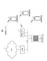
図1は、本実施の形態に係る内線電話システムの概略構成図である。 FIG. 1 is a schematic configuration diagram of an extension telephone system according to the present embodiment.
本実施の形態に係る内線電話システムは、ドアホンシステムと統合されており、図示するように、LAN(Local Area Network)5およびWAN(Wide Area Network)6に接続された主装置1と、主装置1に収容された複数の無線電話端末2−1〜2−3(以下、単に無線電話端末2とも呼ぶ)およびカメラ付きドアホン3と、を有する。 The extension telephone system according to the present embodiment is integrated with a door phone system, and as shown, a
主装置1は、無線電話端末2に内線電話サービスを提供する。また、主装置1は、カメラ付きドアホン3と連携して、訪問者の到来を無線電話端末2に知らせるドアホンサービスを提供する。 The
無線電話端末2は、無線アクセスポイント4およびLAN 5を介して主装置1に接続されており、主装置1が提供する内線電話サービスおよびドアホンサービスを享受する。 The
カメラ付きドアホン3は、呼び出しボタン、マイク、およびカメラを備えており、LAN5を介して接続された主装置1と連携して、無線電話端末2にドアホンサービスを提供する。 The intercom 3 with a camera includes a call button, a microphone, and a camera, and provides intercom service to the
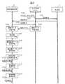
図2および図3は、本実施の形態に係る内線電話システムにおけるドアホンサービスの第一の動作例を説明するためのシーケンス図である。 FIG. 2 and FIG. 3 are sequence diagrams for describing a first operation example of the door phone service in the extension telephone system according to the present embodiment.
カメラ付きドアホン3は、呼び出しボタンが押下されると(S100)、主装置1に接続要求を送信する(S101)。これを受けて、主装置1は、カメラ付きドアホン3に割り当てられた内線番号を発信者番号とする接続要求を無線電話端末2に送信する(S102)。この際、主装置1は、発信元がカメラ付きドアホン3であることを認識し、所定の1以上の無線電話端末2に接続要求を送信してもよいし、あるいは、すべての無線電話端末2に接続要求を送信してもよい。 When the call button is pressed down (S100), camera doorphone 3 transmits a connection request to main device 1 (S101). In response to this,
つぎに、無線電話端末2は、主装置1から接続要求を受信すると、その発信者番号を確認する。そして、発信者番号がカメラ付きドアホン3であるならば、あらかじめ登録されているカメラ付きドアホン3のアドレス情報を用いてカメラ付きドアホン3に映像要求を送信する(S103)。 Next, when receiving the connection request from the
これを受けて、カメラ付きドアホン3は、カメラで撮影した訪問者の映像データ(ストリーミングデータ)の送信を開始し(S105)、無線電話端末2は、カメラ付きドアホン3から送られてくる訪問者の映像データの受信を開始する(S106)。 In response to this, the camera-equipped intercom 3 starts transmitting the video data (streaming data) of the visitor photographed by the camera (S105), and the
つぎに、無線電話端末2は、受信した訪問者の映像データから静止画データを定期的にキャプチャする処理を開始するとともに(S107)、静止画データをキャプチャする毎に、キャプチャした最新の静止画データに基づいて着信画面データを生成する処理を開始する(S108)。さらに、無線電話端末2は、着信画面データを生成する毎に、カメラ付きドアホン3の内線番号に紐付けられている電話帳データに新たに生成した着信画面データを登録・更新する処理を開始する(S109)。 Next, the
それから、無線電話端末2は、着信鳴動を開始するとともに、接続要求の発信者番号に紐付けられている電話帳データから着信画面データを定期的に読み出して、最新の着信画面データに従い着信画面を表示する(S110)。これにより、無線電話端末2には、カメラ付きドアホン3の呼び出しボタンを押下した訪問者の映像データが着信画面として定期的に自動更新されながら表示される。 Then, the
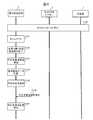
つぎに、無線電話端末2は、着信画面を表示中にタッチパネルがタップされる等、ユーザから所定の更新停止操作を受け付けると(S111)、タッチパネルに表示中の着信画面の自動更新を停止する(S112)。例えば、ユーザは、訪問者を確認しやすい映像が表示された時点で着信画面の自動更新を停止することにより、訪問者の認識精度を向上させることができる。 Next, upon receiving a predetermined update stop operation from the user, such as a tap on the touch panel while displaying the incoming call screen (S111), the
その後、無線電話端末2は、着信画面の自動更新を停止した状態においてタッチパネルが再度タップされる等、ユーザから所定の更新再開操作を受け付けると(S113)、着信画面の自動更新を再開する(S114)。 Thereafter, when the
つぎに、無線電話端末2は、ユーザから応答操作(オフフック)を受け付けると(S115)、着信鳴動および着信画面表示を終了するとともに(S116)、主装置1に接続応答を送信する(S117)。これを受けて、主装置1は、接続要求の送信元であるカメラ付きドアホン3に接続応答を送信する(S118)。これにより、主装置1を介して接続応答を送信した無線電話端末2とカメラ付きドアホン3との間に通話路が確立される(S119)。 Next, upon receiving a response operation (off-hook) from the user (S115), the
その後、カメラ付きドアホン3は、S105で開始した映像データの送信を一旦終了し(S120)。無線電話端末2は、S106で開始した映像データの受信を一旦終了するとともに、S107〜S109で開始した静止画データのキャプチャ、着信画面データの生成、および電話帳データの更新を終了する(S121)。それから、無線電話端末2とカメラ付きドアホン3との間に確立された通話路を介した通話が開始される(S122)。すなわち、無線電話端末2とカメラ付きドアホン3との間で音声データが送受信されるとともに、カメラ付きドアホン3から無線電話端末2へ訪問者の映像データ(ストリーミングデータ)が送信される。 Thereafter, the doorphone with camera 3 temporarily ends the transmission of the video data started in S105 (S120). The
つぎに、無線電話端末2は、ユーザから切断操作(オンフック)を受け付けると(S123)、主装置1に切断要求を送信する(S124)。これを受けて、主装置1は、切断要求元の無線電話端末2との間に通話路が確立されているカメラ付きドアホン3に切断要求を送信する(S125)。 Next, when receiving a disconnection operation (on-hook) from the user (S123), the
つぎに、カメラ付きドアホン3は、主装置1を介して無線電話端末2から切断要求を受信すると切断応答を返信する(S126)。この切断応答は、主装置1を介して、切断要求の送信元である無線電話端末2に送信される(S127)。これにより、無線電話端末2とカメラ付きドアホン3との間の通話路が切断され、両者間の通話が終了する(S128)。 Next, upon receiving the disconnection request from the
その後、無線電話端末2は、カメラ付きドアホン3の内線番号に紐付けられている電話帳データから着信画面データを削除する(S129)。 Thereafter, the
図4は、本実施の形態に係る内線電話システムにおけるドアホンサービスの第二の動作例を説明するためのシーケンス図である。 FIG. 4 is a sequence diagram for describing a second operation example of the door phone service in the extension telephone system according to the present embodiment.
まず、図2のS100〜S110が実施され、無線電話端末2は、着信鳴動を開始するとともに、接続要求元であるカメラ付きドアホン3の内線番号に紐付けられている電話帳データから着信画面データを定期的に読み出して、最新の着信画面データに従い着信画面を表示する(S140)。 First, S100 to S110 in FIG. 2 are performed, and the
ここで、無線電話端末2は、ユーザから応答操作(オフフック)を受け付けることなく、所定時間の経過によりタイムアウトしたものとする(S141)。これにより、無線電話端末2は、着信鳴動および着信画面表示を終了して(S142)、接続要求元であるカメラ付きドアホン3の内線番号と、この内線番号に紐付けられている電話帳データに含まれている着信画面データと、訪問日時と、を含む不応答着信履歴データを登録する(S143)。それから、無線電話端末2は、カメラ付きドアホン3の内線番号に紐付けられている電話帳データから着信画面データを削除するとともに(S144)、不応答着信メッセージを表示する等の所定の不応答着信通知を実施する(S145)。 Here, it is assumed that the
つぎに、無線電話端末2は、不応答着信メッセージを表示中にタッチパネルがタップされる等、ユーザから所定の不応答着信閲覧操作を受け付けると(S146)、登録されている不応答着信履歴データに従い不応答着信履歴を表示する(S147)。具体的には、不応答着信履歴データに含まれている着信画面データが示す訪問者の映像を、不応答着信履歴データに含まれている訪問日時とともに表示する。 Next, when receiving a predetermined unanswered incoming call browsing operation from the user, such as tapping the touch panel while displaying the unanswered incoming call message (S146), the
つぎに、本実施の形態に係る内線電話システムを構成する主装置1、無線電話端末2、およびカメラ付きドアホン3のうち、無線電話端末2の詳細について説明する。 Next, the
なお、主装置1は、既存の主装置と同様である。また、カメラ付きドアホン3は、無線電話端末2からの映像要求に従いカメラで撮像した訪問者の映像データ(ストリーミングデータ)を、主装置1を経由することなく直接、無線電話端末2に送信する点を除き、既存のカメラ付きドアホンと同様である。したがって、主装置1およびカメラ付きドアホン3の詳細な説明を省略する。 The
図5は、無線電話端末2の概略機能構成図である。 FIG. 5 is a schematic functional configuration diagram of the
図示するように、無線電話端末2は、無線インターフェース部200と、マンマシンインターフェース部201と、呼制御部202と、通話処理部203と、電話帳データ記憶部204と、不応答着信履歴データ記憶部205と、映像データ取得部206と、着信画面データ生成部207と、主制御部208と、を有する。 As shown, the
無線インターフェース部200は、無線アクセスポイント4を介してLAN 5に接続するためのインターフェースである。 The
マンマシンインターフェース部201は、ユーザが電話および各種操作を行うためのインターフェースであり、図示していないが、例えば、マイクと、スピーカと、カメラと、ダイヤルキー等の操作部を兼ねたタッチパネルディスプレイと、を備える。 The man-
呼制御部202は、SIP(Session Initiation Protocol)等の呼制御プロトコルに従い、主装置1経由で通話相手(他の無線電話端末2、カメラ付きドアホン3)と呼制御メッセージをやり取りすることにより、通話路の確立・解放を実施する。 The
通話処理部203は、RTP(Realtime Transport Protocol)等の伝送プロトコルに従い、呼制御部202によって確立された通話路を介して、通話相手と通話データを送受信する。 The
具体的には、通話相手が他の無線電話端末2の場合、マンマシンインターフェース部201を介してユーザにより入力された音声信号および映像信号を通話データに符号化し、この通話データを通話路経由で通信相手に送信するとともに、通信相手から通話路経由で通話データを受信し、この通話データを音声信号および映像信号に復号してマンマシンインターフェース部201から出力する。また、通話相手がカメラ付きドアホン3の場合、マンマシンインターフェース部201を介してユーザにより入力された音声信号を通話データに符号化し、この通話データを通話路経由で通信相手に送信するとともに、通信相手から通話路経由で通話データを受信し、この通話データを音声信号および映像信号に復号してマンマシンインターフェース部201から出力する。 Specifically, when the other party is another
電話帳データ記憶部204には、電話番号毎に電話帳データが記憶されている。 The telephone directory
図6は、電話帳データ記憶部204の登録内容を模式的に表した図である。 FIG. 6 is a diagram schematically showing the registered contents of the telephone directory
図示するように、電話帳データ記憶部204には、電話番号毎に、電話帳データのレコード2040が記憶されている。電話帳データのレコード2040は、電話番号を登録するフィールド2041と、氏名、所属等のユーザ情報を登録するフィールド2042と、着信の際に利用する着信画面データ(あるいはその格納場所)を登録するフィールド2043と、を有する。なお、電話帳データ記憶部204に記憶されている電話帳データのレコード2040の一つは、カメラ付きドアホン3に関するものであり、フィールド2041にはカメラ付きドアホン3の内線番号が登録され、フィールド2042にはカメラ付きドアホン3であることを示す情報が登録される。また、フィールド2043には、カメラ付きドアホン3から着信を受けると、その着信画面データ等が登録され(図2のS109)、カメラ付きドアホン3からの着信に不応答か、あるいはカメラ付きドアホン3との通話が終了すると、その登録内容が削除される(図3のS129、図4のS144)。 As shown, the telephone directory
不応答着信履歴データ記憶部205には、不応答の着信毎に不応答着信履歴データが記憶される。 The unanswered incoming call history
図7は、不応答着信履歴データ記憶部205の登録内容を模式的に表した図である。 FIG. 7 is a diagram schematically illustrating the registered contents of the non-response incoming call history
図示するように、不応答着信履歴データ記憶部205には、不応答の着信毎に、不応答着信履歴データのレコード2050が記憶されている。不応答着信履歴データのレコード2050は、不応答であった着信の発信元の電話番号を登録するフィールド2051と、この着信の日時を登録するフィールド2052と、不応答であった着信の発信元がカメラ付きドアホン3である場合に、その訪問者の映像データから生成された着信画面データ(あるいはその格納場所)を登録するフィールド2053と、を有する。 As shown, the unanswered incoming call history
映像データ取得部206は、主装置1からカメラ付きドアホン3を発信元とする着信を受信した場合に、カメラ付きドアホン3から訪問者の映像データ(ストリーミングデータ)を取得する。 The video
着信画面データ生成部207は、映像データ取得部206により取得された訪問者の映像データに基づいて、定期的に、カメラ付きドアホン3用の着信画面データを生成する。具体的には、訪問者の映像データ(ストリーミングデータ)から定期的に静止画データをキャプチャし、これをカメラ付きドアホン3用の着信画面データとする。 The incoming call screen
主制御部208は、無線電話端末2の各部200〜207を統括的に制御する。また、主制御部208は、電話帳データ記憶部204に記憶されている電話帳データのレコード2040の更新、および、不応答着信履歴データ記憶部205への不応答着信履歴データのレコード2050の登録を行う。さらに、主制御部208は、マンマシンインターフェース部201を介してユーザより受け付けた不応答着信閲覧操作に従い、不応答着信履歴データ記憶部205に記憶されている不応答着信履歴データのレコード2050をマンマシンインターフェース部201に表示する。 The
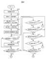
図8および図9は、無線電話端末2のドアホンサービス処理を説明するためのフロー図である。 FIG. 8 and FIG. 9 are flowcharts for explaining the intercom service processing of the
このフローは、カメラ付きドアホン3を発信元とする接続応答(着信)を主装置1から受信することにより開始される。 This flow is started when a connection response (incoming call) having the camera intercom 3 as a transmission source is received from the
まず、呼制御部202は、電話帳データ記憶部204を参照して、接続応答の発信者番号がカメラ付きドアホン3の内線番号であることを確認し、その旨を主制御部208に知らせる。これを受けて、主制御部208は、映像データ取得部206に映像データの取得開始を指示する。映像データ取得部206は、主制御部208の指示に従い、無線インターフェース部200を介してカメラ付きドアホン3に映像要求を送信し(S200)、カメラ付きドアホン3から送られてくる訪問者の映像データ(ストリーミングデータ)の受信を開始する(S201)。 First, the
映像データ取得部206による訪問者の映像データの受信が開始すると、着信画面データ生成部207は、定期的に、この訪問者の映像データから静止画データをキャプチャして、カメラ付きドアホン3用の着信画面データを生成する処理を開始する(S202)。また、着信画面データ生成部207によりカメラ付きドアホン3用の着信画面データが生成される毎に、主制御部208は、電話帳データ記憶部204から、カメラ付きドアホン3の内線番号がフィールド2041に登録されている電話帳データのレコード2040を検索し、このレコード2040のフィールド2043に、着信画面データ生成部207により生成された最新の着信画面データ(あるいはその格納場所)を登録・更新する処理を開始する(S203)。 When the reception of the video data of the visitor by the video
その後、主制御部208は、呼制御部202に着信通知を指示する。これを受けて、呼制御部202は、マンマシンインターフェース部201から着信鳴動音を出力するとともに、電話帳データ記憶部204に記憶されている、カメラ付きドアホン3の内線番号がフィールド2041に登録されている電話帳データのレコード2040に基づいて、マンマシンインターフェース部201に着信画面を表示する(S204)。 After that, the
図10は、着信画面の表示例を示す図である。 FIG. 10 is a diagram illustrating a display example of the incoming call screen.
図示するように、着信画面には、電話帳データ記憶部204に記憶されている電話帳データによりカメラ付きドアホン3の内線番号に対応付けられる着信画面データ(フィールド2041にカメラ付きドアホン3の内線番号が登録されている電話帳データのレコード2040のフィールド2043に登録されている着信画面データ、あるいは、このフィールド2043に登録されている格納場所に格納された着信画面データ)が表す訪問者の映像210が、このレコード2040のフィールド2042に登録されている、カメラ付きドアホン3であることを示すユーザ情報211とともに表示される。また、着信画面には、例えば、応答操作を受け付けるための応答ボタン212、着信拒否操作を受け付けるための拒否ボタン213が表示されている。 As shown in the figure, the incoming call screen has incoming call screen data associated with the extension number of the camera-equipped intercom 3 based on the phonebook data stored in the phonebook data storage unit 204 (the extension number of the camera-equipped intercom 3 is displayed in the field 2041). Of the visitor represented by the incoming call screen data registered in the
つぎに、呼制御部202は、電話帳データ記憶部204に記憶されている電話帳データによりカメラ付きドアホン3の内線番号に対応付けられる着信画面データが更新されると(S205でYES)、更新された着信画面データに基づいて着信画面を更新する(S206)。 Next, when the incoming call screen data associated with the extension number of the camera intercom 3 is updated by the telephone directory data stored in the telephone directory data storage unit 204 (YES in S205), the
また、呼制御部202は、着信画面内の訪問者の映像210をタップする等の所定の更新停止操作をマンマシンインターフェース部201が受け付けると(S209でYES)、着信画面内の訪問者の映像210を再度タップする等の所定の更新再開操作をマンマシンインターフェース部201が受け付けるまで(S210でYES)、電話帳データ記憶部204に記憶されている電話帳データによりカメラ付きドアホン3の内線番号に対応付けられる着信画面データの更新にかかわらず、着信画面を固定する。これにより、例えば、訪問者を確認しやすい映像が表示された時点で着信画面の自動更新を停止することにより、訪問者の認識精度を向上させることができる。 Further, when the man-
また、呼制御部202は、着信画面内の応答ボタン212をタップする等の所定の応答操作(オフフック操作)をマンマシンインターフェース部201が受け付けると(S208またはS211でYES)、マンマシンインターフェース部201に対する着信鳴動音の出力および着信画面の表示を終了するとともに(S213)、無線インターフェース部200を介して主装置1に接続応答を送信する(S214)。これにより、通話相手であるカメラ付きドアホン3との間に通話路が確立される。 When the man-
それから、呼制御部202は、カメラ付きドアホン3からの着信に応答した旨を主制御部208に知らせる。これを受けて、主制御部208は、映像データ取得部206に映像データの取得停止を指示する。これを受けて、映像データ取得部206は、カメラ付きドアホン3から送られてくる映像データの受信を終了する。これにより、着信画面データ生成部207における静止画データのキャプチャおよびカメラ付きドアホン3用の着信画面データの生成が終了する。また、主制御部208による、電話帳データ記憶部204に記憶されている電話帳データによりカメラ付きドアホン3の内線番号に対応付けられる着信画面データの更新も終了する(S215)。 Then, the
つぎに、呼制御部202は、通話処理部203に、通話相手であるカメラ付きドアホン3との間に確立された通話路を通知して通話の開始を指示する。これにより、通話処理部203は、呼制御部202より通知された通話路を介して、通話相手であるカメラ付きドアホン3との通話を開始する(S216)。 Next, the
その後、呼制御部202は、マンマシンインターフェース部201がユーザから所定の切断操作(オンフック操作)を受け付けると(S217でYES)、無線インターフェース部200を介して主装置1に切断要求を送信する。これにより、通話相手であるカメラ付きドアホン3との間の通話路が切断され、通話処理部203によるカメラ付きドアホン3との通話が終了する(S218)。 Thereafter, when man-
つぎに、主制御部208は、電話帳データ記憶部204に記憶されている電話帳データによりカメラ付きドアホン3の内線番号に対応付けられる着信画面データを削除する(S219)。 Next, the
また、呼制御部202は、応答操作、更新停止操作、および更新再開操作のいずれの操作もマンマシンインターフェース部201が受け付けることなく(S208、S209でNO、あるいはS210、S211でNO)、所定時間(例えば15秒)の経過によりタイムアウトするか、あるいは着信画面内の拒否ボタン213をタップする等の所定の着信拒否操作をマンマシンインターフェース部201が受け付けると(S207あるいはS212でYES)、マンマシンインターフェース部201に対する着信鳴動音の出力および着信画面の表示を終了する(S220)。 Further, the
それから、呼制御部202は、カメラ付きドアホン3からの着信に不応答である旨を主制御部208に知らせる。これを受けて、主制御部208は、映像データ取得部206に映像データの受信終了を指示する。この指示に従い、映像データ取得部206は、カメラ付きドアホン3から送られてくる映像データの受信を終了する。これにより、着信画面データ生成部207における静止画データのキャプチャおよびカメラ付きドアホン3用の着信画面データの生成が終了する。また、電話帳データ記憶部204に記憶されている電話帳データによりカメラ付きドアホン3の内線番号に対応付けられる着信画面データの、主制御部208による更新も終了する(S221)。 Then, the
つぎに、主制御部208は、不応答着信履歴データ記憶部205に新たな不応答着信履歴データのレコード2050を追加し、このレコード2050のフィールド2051にカメラ付きドアホン3の内線番号を登録し、フィールド2052にカメラ付きドアホン3を発信元とする接続要求の着信日時を登録し、そして、フィールド2053に、電話帳データ記憶部204に記憶されている電話帳データによりカメラ付きドアホン3の内線番号に対応付けられる着信画面データあるいはこの着信画面データの格納場所を登録する(S222)。 Next, the
それから、主制御部208は、電話帳データ記憶部204に記憶されている電話帳データによりカメラ付きドアホン3の内線番号に対応付けられる着信画面データを削除するとともに(S223)、不応答着信があることを知らせる不応答着信メッセージをマンマシンインターフェース部201に表示する(S224)。なお、この不応答着信メッセージは、S222において不応答着信履歴データ記憶部205に追加した不応答着信履歴データのレコード2050に紐付けておく。 Then, the
その後、主制御部208は、表示中の不応答着信メッセージをタップする等の所定の不応答着信閲覧操作をマンマシンインターフェース部201が受け付けると(S225でYES)、この不応答着信メッセージに紐付けられている不応答着信履歴データのレコード2050に基づいて、マンマシンインターフェース部201に不応答着信履歴を表示する(S226)。 Thereafter, when the man-
図11は、不応答着信履歴の表示例を示す図である。 FIG. 11 is a diagram illustrating a display example of the unanswered incoming call history.
図示するように、不応答着信閲覧操作された不応答着信メッセージに紐付けられている不応答着信履歴データのレコード2050のフィールド2053に登録されている着信画面データが表す訪問者の映像220が、このレコード2050のフィールド2051、2052に登録されている電話番号221および着信日時222とともに、不応答着信履歴として表示される。ただし、電話番号221がフィールド2041に登録されている電話帳データのレコード2040が電話帳データ記憶部204に記憶されている場合は、このレコード2040のフィールド2042に登録されているユーザ情報(図11の表示例では、カメラ付きドアホン3であることを示すユーザ情報)が、電話番号221の代わりに表示される。 As shown in the figure, the
以上、本発明の一実施の形態を説明した。 Hereinabove, one embodiment of the present invention has been described.
本実施の形態において、無線電話端末2は、カメラ付きドアホン3からの着信を受信すると、カメラ付きドアホン3の呼び出しボタンを押した訪問者の映像データを取得し、取得した映像データからカメラ付きドアホン3用の着信画面データを生成してカメラ付きドアホン3の内線番号に対応付けて記憶する。それから、無線電話端末2は、カメラ付きドアホン3の内線番号に対応付けられて記憶されている着信画面データに従い着信画面を表示して、カメラ付きドアホン3からの着信を知らせる。このため、本実施の形態によれば、例えばアップル社のオペレーティングシステムであるiOSのCall Kitを利用した電話アプリケーションプログラムにより実現される無線電話端末等の、カメラ付きドアホン3に対応していない無線電話端末2でも、カメラ付きドアホン3からの着信応答前に、カメラ付きドアホン3の呼び出しボタンを押した訪問者の映像を確認することができる。 In the present embodiment, when receiving an incoming call from the camera-equipped doorphone 3, the
また、本実施の形態において、無線電話端末2は、ストリーミングデータである訪問者の映像データから静止画データをキャプチャしてカメラ付きドアホン3用の着信画面データを生成し、これをカメラ付きドアホン3の内線番号に対応付けて記憶する。このため、本実施の形態によれば、ストリーミングデータである訪問者の映像データそのものをカメラ付きドアホン3の内線番号に対応付けて記憶する必要がなく、記憶領域の消費を抑制することができる。 Further, in the present embodiment, the
また、本実施の形態において、無線電話端末2は、ストリーミングデータである訪問者の映像データから定期的に静止画データをキャプチャし、キャプチャした最新の静止画データをカメラ付きドアホン3用の着信画面データとして、カメラ付きドアホン3の内線番号に対応付けて記憶している着信画面データを更新する。また、カメラ付きドアホン3の内線番号に対応付けて記憶している着信画面データが更新される毎に、更新された着信画面データを読み出して表示中の着信画面を更新する。このため、本実施の形態によれば、着信画面に表示される訪問者の映像が定期的に自動更新されるので、訪問者の認識精度を向上させることができる。 In the present embodiment, the
また、本実施の形態において、無線電話端末2は、カメラ付きドアホン3用の着信画面の表示中に、ユーザから更新停止操作を受け付けた場合、表示中の着信画面の自動更新を停止する。このため、例えば訪問者を確認しやすい映像が表示された時点で着信画面の自動更新を停止することにより、訪問者の認識精度をさらに向上させることができる。 Further, in the present embodiment, when an update stop operation is received from the user while the incoming call screen for camera intercom 3 is being displayed,
また、本実施の形態において、無線電話端末2は、カメラ付きドアホン3からの着信に応答することなく所定時間の経過によりタイムアウトした場合に、カメラ付きドアホン3の内線番号に対応付けられて記憶されている着信画面データを含む不応答着信履歴データを作成して記憶する。そして、ユーザから不応答着信閲覧操作を受け付けた場合に、不応答着信履歴データにより特定される着信画面を含む不応答着信履歴を表示する。このため、本実施の形態によれば、会議等の所用により応答できなかった訪問者を後から映像で確認することができる。 Further, in the present embodiment, when the
なお、本発明は上記の実施の形態に限定されるものではなく、その要旨の範囲内で数々の変形が可能である。 It should be noted that the present invention is not limited to the above embodiment, and various modifications can be made within the scope of the gist.
例えば、上記の実施の形態において、無線電話端末2は、ストリーミングデータである訪問者の映像データから定期的に静止画データをキャプチャして、キャプチャした最新の静止画データをカメラ付きドアホン3用の着信画面データとしている。しかし、本発明はこれに限定されない。ストリーミングデータである訪問者の映像データから定期的に静止画データをキャプチャし、静止画データをキャプチャする毎に、最新の静止画データを含むこれまでにキャプチャした複数の静止画データに基づいてカメラ付きドアホン3用の着信画面データを生成してもよい。 For example, in the above embodiment, the
図12は、着信画面の変形例を示す図である。 FIG. 12 is a diagram showing a modification of the incoming call screen.
図示するように、変形例に係る着信画面には、電話帳データ記憶部204に記憶されている電話帳データによりカメラ付きドアホン3の内線番号に対応付けられる着信画面データ(フィールド2041にカメラ付きドアホン3の内線番号が登録されている電話帳データのレコード2040のフィールド2043に登録されている着信画面データ、あるいは、このフィールド2043の登録されている格納場所に格納された着信画面データ)が表す映像210が表示されており、この映像210は、最新の静止画データを含むこれまでにキャプチャした複数の静止画データが表す訪問者の映像210−1〜210−4で構成されている。ここで、符号210−1は、最新のキャプチャされた静止画データが表す訪問者の映像であり、符号210−2は、1つ前にキャプチャされた静止画データが表す訪問者の映像であり、符号210−3は、2つ前にキャプチャされた静止画データが表す訪問者の映像であり、符号210−4は、3つ前にキャプチャされた静止画データが表す訪問者の映像である。このように、直近にキャプチャされた複数の静止画データが表す一連の映像210−1〜210−4を含む訪問者の映像210を確認できるようにすることにより、訪問者の認識精度をさらに向上させることができる。 As shown in the drawing, the incoming call screen according to the modification includes incoming call screen data associated with the extension number of the camera-equipped door phone 3 based on the phone book data stored in the phone book data storage unit 204 (the field-equipped door phone with camera The video represented by the incoming call screen data registered in the
また、上記の実施の形態において、無線電話端末2は、ストリーミングデータである訪問者の映像データから定期的に静止画データをキャプチャしているが、本発明はこれに限定されない。訪問者の映像データから一度だけキャプチャされた静止画データを継続的に着信画面データとして使用することにより、無線電話端末2における処理負荷を低減するようにしてもよい。 Further, in the above embodiment, the
また、上記の実施の形態において、無線電話端末2は、カメラ付きドアホン3を発信元とする接続要求を主装置1から受信した場合に、カメラ付きドアホン3に映像要求を送信することにより、主装置1を経由しないで、カメラ付きドアホン3から訪問者の映像データを取得している。しかしながら、本発明はこれに限定されない。無線電話端末2は、カメラ付きドアホン3で撮影された訪問者の映像データを主装置1経由で取得してもよい。 Further, in the above embodiment, when the
すなわち、主装置1は、カメラ付きドアホン3から接続要求を受信すると、カメラ付きドアホン3を発信元とする接続要求を無線電話端末2に送信するとともに、カメラ付きドアホン3に映像要求を送信し、カメラ付きドアホン3から訪問者の映像データを受信して無線電話端末2に送信する。これにより、無線電話端末2は、カメラ付きドアホン3を発信元とする接続要求を主装置1から受信すると、続けて、カメラ付きドアホン3で撮影された訪問者の映像データを主装置1から受信する。 That is, when receiving a connection request from the camera-equipped doorphone 3, the
ここで、主装置1は、カメラ付きドアホン3から受信した訪問者の映像データ(ストリーミングデータ)から静止画データをキャプチャし、これをカメラ付きドアホン3用の着信画面データとして無線電話端末2に送信してもよい。この場合、無線電話端末2において、着信画面データ生成部207は不要である。主制御部208は、映像データ取得部206により取得されたカメラ付きドアホン3用の着信画面データを、電話帳データ記憶部204の電話帳データに記憶されているカメラ付きドアホン3の内線番号に対応付けて記憶(着信画面データあるいはその格納場所を、フィールド2041にカメラ付きドアホン3の内線番号が登録されている電話帳データのレコード2040のフィールド2043に登録)する。 Here,
また、ここで、主装置1は、カメラ付きドアホン3から受信した訪問者の映像データから定期的に静止画データをキャプチャして、キャプチャされた最新の静止画データをカメラ付きドアホン3用の着信画面データとして無線電話端末2に送信してもよい。あるいは、主装置1は、カメラ付きドアホン3から受信した訪問者の映像データから定期的に静止画データをキャプチャし、静止画データをキャプチャする毎に、最新の静止画データを含むこれまでにキャプチャした複数の静止画データに基づいてカメラ付きドアホン3用の着信画面データを生成してもよい。これらの場合、映像データ取得部206がカメラ付きドアホン3用の着信画面データを受信する都度、主制御部208は、電話帳データ記憶部204に記憶されている電話帳データによりカメラ付きドアホン3の内線番号に対応付けられる着信画面データ(フィールド2041にカメラ付きドアホン3の内線番号が登録されている電話帳データのレコード2040のフィールド2043に登録されている着信画面データ、あるいは、このフィールド2043に登録されている格納場所に格納された着信画面データ)を、新たに受信したカメラ付きドアホン3用の着信画面データに更新する。 Further, here, the
また、上記の実施の形態において、図5に示す無線電話端末2の機能構成は、ASIC(Application Specific Integrated Circuit)、FPGA(Field Programmable Gate Array)などの集積ロジックICによりハード的に実現されるものでもよいし、あるいはDSP(Digital Signal Processor)などの計算機によりソフトウエア的に実現されるものでもよい。または、CPU(Central Processing Unit)と、メモリと、SSD(Solid State Drive)、フラッシュメモリ等の補助記憶装置、および無線LANアダプタ等の無線通信機を備えたスマートホン、タブレットPC(Personal Computer)等の汎用コンピュータにおいて、CPUが所定のプログラムを補助記憶装置からメモリ上にロードして実行することで実現されるものでもよい。 Further, in the above embodiment, the functional configuration of the
また、上記の実施の形態では、主装置1に収容される内線端末として無線電話端末2を例にとり説明したが、内線端末は無線電話端末に限らず、電話番号と映像データとを対応付けて登録可能なアドレス帳機能と、アドレス帳に登録された電話番号からの着信を、映像データを含む着信通知画面の表示で通知する着信通知機能とを有する通話アプリケーションがインストールされた固定端末でもよい。 Further, in the above-described embodiment, the
1:主装置 2、2−1〜2−3:無線電話端末 3:カメラ付きドアホン
4:無線アクセスポイント 5:LAN 6:WAN
200:無線インターフェース部 201:マンマシンインターフェース部
202:呼制御部 203:通話処理部 204:電話帳データ記憶部
205:不応答着信履歴データ記憶部 206:映像データ取得部
207:着信画面データ生成部 208:主制御部
1:
200: wireless interface unit 201: man-machine interface unit 202: call control unit 203: call processing unit 204: telephone directory data storage unit 205: unanswered incoming call history data storage unit 206: video data acquisition unit 207: incoming screen data generation unit 208: Main control unit
Claims (13)
Translated fromJapanese前記カメラ付きドアホンを発信元とする着信を前記主装置から受信した場合に、当該カメラ付きドアホンが撮像している訪問者の映像データを取得する映像データ取得手段と、
前記映像データ取得手段により取得された前記訪問者の映像データを、着信画面データとして、前記カメラ付きドアホンの番号情報に対応付けて記憶する着信画面データ記憶手段と、
前記主装置から着信を受信した場合に、当該着信の発信元の番号情報に対応付けられて前記着信画面データ記憶手段に記憶されている前記着信画面データを読み出し、当該読み出した前記着信画面データに従い着信画面を表示して、当該着信を知らせる着信表示手段と、を備える
ことを特徴とする電話端末。A telephone terminal housed in a main device housing a door phone with a camera and functioning as an extension terminal,
When receiving an incoming call from the main apparatus with the camera doorphone as a source, video data obtaining means for obtaining video data of a visitor being imaged by the camera doorphone,
Incoming screen data storage means for storing the video data of the visitor obtained by the video data obtaining means as incoming screen data in association with the camera intercom number information,
When an incoming call is received from the main device, the incoming call screen data stored in the incoming call screen data storage means is read in association with the caller's number information of the incoming call, and according to the read out incoming call screen data. An incoming call display means for displaying an incoming call screen and informing the user of the incoming call.
前記映像データ取得手段により取得された前記訪問者の映像データから前記着信画面データを生成する着信画面データ生成手段をさらに備え、
前記着信画面データ記憶手段は、
前記着信画面データ生成手段により生成された前記着信画面データを、前記カメラ付きドアホンの番号情報に対応付けて記憶する
ことを特徴とする電話端末。The telephone terminal according to claim 1, wherein
Further provided is an incoming screen data generating means for generating the incoming screen data from the video data of the visitor obtained by the video data obtaining means,
The incoming screen data storage means,
A telephone terminal, wherein the incoming call screen data generated by the incoming call screen data generating means is stored in association with the number information of the camera intercom.
前記訪問者の映像データは、ストリーミングデータであり、
前記着信画面データ生成手段は、
前記映像データ取得手段により取得された前記訪問者の映像データから静止画データをキャプチャして、前記着信画面データを生成する
ことを特徴とする電話端末。The telephone terminal according to claim 2, wherein
The visitor's video data is streaming data,
The incoming screen data generating means,
A telephone terminal that captures still image data from the video data of the visitor obtained by the video data obtaining unit and generates the incoming screen data.
前記着信画面データ生成手段は、
定期的に、前記映像データ取得手段により取得された前記訪問者の映像データから静止画データをキャプチャして、当該キャプチャした最新の前記静止画データを前記着信画面データとし、
前記着信画面データ記憶手段は、
前記着信画面データ生成手段によって前記着信画面データが生成される毎に、前記カメラ付きドアホンの番号情報に対応付けられて記憶されている前記着信画面データを、前記着信画面データ生成手段によって生成された最新の前記静止画データに更新し、
前記着信表示手段は、
前記主装置から着信を受信した場合に、当該着信の発信元の番号情報に対応付けられて前記着信画面データ記憶手段に記憶されている前記着信画面データが更新される毎に、当該着信画面データを読み出して表示中の前記着信画面を更新する
ことを特徴とする電話端末。The telephone terminal according to claim 3, wherein
The incoming screen data generating means,
Periodically, capture still image data from the video data of the visitor obtained by the video data obtaining means, and the latest captured still image data as the incoming screen data,
The incoming screen data storage means,
Each time the incoming screen data generating means generates the incoming screen data, the incoming screen data stored in association with the number information of the camera intercom is generated by the incoming screen data generating means. Update to the latest still image data,
The incoming call display means,
When an incoming call is received from the main unit, every time the incoming screen data stored in the incoming screen data storage unit is updated in association with the number information of the source of the incoming call, the incoming screen data is updated. And updating the incoming call screen being displayed by reading out the incoming call screen.
前記着信画面データ生成手段は、
定期的に、前記映像データ取得手段により取得された前記訪問者の映像データから静止画データをキャプチャするとともに、これまでにキャプチャした複数の前記静止画データに基づいて、前記着信画面データを生成し、
前記着信画面データ記憶手段は、
前記着信画面データ生成手段によって前記着信画面データが生成される毎に、前記カメラ付きドアホンの番号情報に対応付けられて記憶されている前記着信画面データを、前記着信画面データ生成手段によって生成された最新の前記静止画データに更新し、
前記着信表示手段は、
前記主装置から着信を受信した場合に、当該着信の発信元の番号情報に対応付けられて前記着信画面データ記憶手段に記憶されている前記着信画面データが更新される毎に、当該着信画面データを読み出して表示中の前記着信画面を更新する
ことを特徴とする電話端末。The telephone terminal according to claim 3, wherein
The incoming screen data generating means,
Periodically, while capturing still image data from the video data of the visitor obtained by the video data obtaining means, generating the incoming screen data based on the plurality of still image data captured so far. ,
The incoming screen data storage means,
Each time the incoming screen data generating means generates the incoming screen data, the incoming screen data stored in association with the number information of the camera intercom is generated by the incoming screen data generating means. Update to the latest still image data,
The incoming call display means,
When an incoming call is received from the main unit, every time the incoming screen data stored in the incoming screen data storage unit is updated in association with the number information of the source of the incoming call, the incoming screen data is updated. And updating the incoming call screen being displayed by reading out the incoming call screen.
前記着信表示手段は、
ユーザから所定の操作を受け付けた場合に、表示中の前記着信画面の更新を停止する
ことを特徴とする電話端末。The telephone terminal according to claim 4 or 5,
The incoming call display means,
A telephone terminal, which stops updating the incoming call screen being displayed when a predetermined operation is received from a user.
前記着信画面データ記憶手段は、
前記カメラ付きドアホンからの着信通知に応答して開始された前記カメラ付きドアホンとの通話が終了した場合、あるいは、前記カメラ付きドアホンからの着信通知に応答することなく所定時間を経過した場合に、前記カメラ付きドアホンの番号情報に対応付けて記憶している前記着信画面データを消去する
ことを特徴とする電話端末。The telephone terminal according to any one of claims 1 to 6, wherein
The incoming screen data storage means,
When the call with the camera intercom started in response to the incoming call notification from the camera intercom ends, or when a predetermined time has elapsed without responding to the incoming call notification from the camera intercom, A telephone terminal that deletes the incoming call screen data stored in association with the number information of the intercom with a camera.
前記カメラ付きドアホンからの着信通知に応答することなく所定時間を経過した場合に、前記カメラ付きドアホンの番号情報に対応付けられて前記着信画面データ記憶手段に記憶されている前記着信画面データを含む訪問者情報を記憶する訪問者情報記憶手段と、
ユーザから受け付けた指示に従い、前記訪問者情報記憶手段に記憶されている前記訪問者情報に含まれている前記着信画面データにより特定される前記着信画面を含む訪問者情報を表示する訪問者情報表示手段と、をさらに備える
ことを特徴とする電話端末。The telephone terminal according to claim 1, wherein:
When a predetermined time has elapsed without responding to an incoming call notification from the intercom with camera, the incoming call screen data stored in the incoming call screen data storage unit in association with the number information of the intercom with camera is included. Visitor information storage means for storing visitor information;
A visitor information display for displaying visitor information including the incoming call screen specified by the incoming call screen data included in the visitor information stored in the visitor information storage means according to an instruction received from a user. Means, further comprising:
前記電話端末およびカメラ付きドアホンを収容する主装置と、を有し、
前記主装置は、
前記カメラ付きドアホンから着信を受信した場合に、当該着信を前記電話端末に送信するドアホン着信通知手段と、
前記カメラ付きドアホンから着信を受信した場合に、当該カメラ付きドアホンから撮像中の訪問者の映像データを取得して、前記電話端末に送信するドアホン映像送信手段と、を備える
ことを特徴とする内線電話システム。A telephone terminal according to claim 1,
A main device that houses the telephone terminal and a door phone with a camera,
The main device,
When receiving an incoming call from the camera doorphone, intercom incoming notification means for transmitting the incoming call to the telephone terminal,
And an intercom image transmitting means for acquiring video data of a visitor being imaged from the intercom with camera when receiving an incoming call from the intercom with camera, and transmitting the video data to the telephone terminal. Phone system.
前記訪問者の映像データは、ストリーミングデータであり、
前記ドアホン映像送信手段は、
定期的に、前記カメラ付きドアホンから取得した前記訪問者の映像データから静止画データをキャプチャして、当該キャプチャした最新の前記静止画データを前記着信画面データとして前記電話端末に送信し、
前記映像データ取得手段は、
前記訪問者の映像データに代えて前記着信画面データを取得し、
前記着信画面データ記憶手段は、
前記映像データ取得手段によって前記着信画面データが取得される毎に、前記カメラ付きドアホンの番号情報に対応付けられて記憶されている前記着信画面データを最新の前記着信画面データに更新し、
前記着信表示手段は、
前記主装置から着信を受信した場合に、当該着信の発信元の番号情報に対応付けられて前記着信画面データ記憶手段に記憶されている前記着信画面データが更新される毎に、当該着信画面データを読み出して表示中の前記着信画面を更新する
ことを特徴とする内線電話システム。The extension telephone system according to claim 9, wherein
The visitor's video data is streaming data,
The intercom image transmission means,
Periodically, capture still image data from the video data of the visitor acquired from the camera intercom, and transmit the captured latest still image data to the telephone terminal as theincoming screen data,
The video data acquisition means,
Acquiring the incoming screen data instead of the visitor's video data,
The incoming screen data storage means,
Each time theincoming screen data is acquired by the video data acquiring means, theincoming screen data stored in association with the number information of the camera intercom is updated to the latestincoming screen data,
The incoming call display means,
When an incoming call is received from the main unit, every time the incoming screen data stored in the incoming screen data storage unit is updated in association with the number information of the source of the incoming call, the incoming screen data is updated. , And updates the incoming call screen being displayed.
前記訪問者の映像データは、ストリーミングデータであり、
前記ドアホン映像送信手段は、
定期的に、前記カメラ付きドアホンから取得した前記訪問者の映像データから静止画データをキャプチャするとともに、これまでにキャプチャした複数の前記静止画データに基づいて、前記着信画面データを生成して送信し、
前記映像データ取得手段は、
前記訪問者の映像データに代えて前記着信画面データを取得し、
前記着信画面データ記憶手段は、
前記映像データ取得手段によって前記着信画面データが取得される毎に、前記カメラ付きドアホンの番号情報に対応付けられて記憶されている前記着信画面データを、最新の前記着信画面データに更新し、
前記着信表示手段は、
前記主装置から着信を受信した場合に、当該着信の発信元の番号情報に対応付けられて前記着信画面データ記憶手段に記憶されている前記着信画面データが更新される毎に、当該着信画面データを読み出して表示中の前記着信画面を更新する
ことを特徴とする内線電話システム。The extension telephone system according to claim 9, wherein
The visitor's video data is streaming data,
The intercom image transmission means,
Periodically, capture stillimage data from thevideo data of the visitor obtained from the camera door phone, and generate and transmit theincoming screen data based on the plurality of still image data captured so far. And
The video data acquisition means,
Acquiring the incoming screen data instead of the visitor's video data,
The incoming screen data storage means,
Each time theincoming screen data is acquired by the video data acquiring means, theincoming screen data stored in association with the number information of the camera intercom is updated to the latestincoming screen data ,
The incoming call display means,
When an incoming call is received from the main unit, every time the incoming screen data stored in the incoming screen data storage unit is updated in association with the number information of the source of the incoming call, the incoming screen data is updated. , And updates the incoming call screen being displayed.
前記プログラムは、
前記コンピュータを、カメラ付きドアホンを収容する主装置に収容されて、内線端末として機能する電話端末として機能させ、
前記電話端末は、
前記主装置から前記カメラ付きドアホンを発信元とする着信を受信した場合に、当該カメラ付きドアホンが撮像している訪問者の映像データを取得する映像データ取得手段と、
前記映像データ取得手段により取得された前記訪問者の映像データを、着信画面データとして、前記カメラ付きドアホンの番号情報に対応付けて記憶する着信画面データ記憶手段と、
前記主装置から着信を受信した場合に、当該着信の発信元の番号情報に対応付けられて前記着信画面データ記憶手段に記憶されている前記着信画面データを読み出し、当該読み出した前記着信画面データに従い着信画面を表示して、当該着信を知らせる着信表示手段と、を備える
ことを特徴とするコンピュータで読み取り可能なプログラム。A computer readable program,
The program is
The computer is housed in a main device that houses a door phone with a camera, and functions as a telephone terminal that functions as an extension terminal.
The telephone terminal,
When receiving an incoming call from the main device with the camera doorphone as a source, video data obtaining means for obtaining video data of a visitor being imaged by the camera doorphone,
Incoming screen data storage means for storing the video data of the visitor obtained by the video data obtaining means as incoming screen data in association with the camera intercom number information,
When an incoming call is received from the main device, the incoming call screen data stored in the incoming call screen data storage means is read in association with the caller's number information of the incoming call, and according to the read out incoming call screen data. A computer readable program comprising: an incoming call display screen that displays an incoming call screen and notifies the user of the incoming call.
前記電話端末は、
当該電話端末および前記カメラ付きドアホンを収容する主装置から前記カメラ付きドアホンを発信元とする着信を受信した場合に、
当該カメラ付きドアホンが撮像している訪問者の映像データを取得して、当該訪問者の映像データを、着信画面データとして、前記カメラ付きドアホンの番号情報に対応付けて記憶し、
当該着信の発信元である前記カメラ付きドアホンの番号情報に対応付けられて記憶されている前記着信画面データを読み出し、当該読み出した前記着信画面データに従い着信画面を表示して、当該着信を知らせる
ことを特徴とするカメラ付きドアホンからの着信通知方法。
A method for notifying an incoming call from a camera intercom in a telephone terminal,
The telephone terminal,
When receiving an incoming call from the main unit that houses the telephone terminal and the camera door phone, the call originating from the camera door phone,
Acquiring the video data of the visitor being imaged by the camera intercom, storing the video data of the visitor as incoming screen data in association with the number information of the camera intercom,
Reading the incoming call screen data stored in association with the number information of the intercom with camera that is the source of the incoming call, displaying the incoming call screen in accordance with the read out incoming call screen data, and notifying the incoming call. A method for notifying an incoming call from a door phone with a camera.
Priority Applications (1)
| Application Number | Priority Date | Filing Date | Title |
|---|---|---|---|
| JP2019111135AJP6645608B1 (en) | 2019-06-14 | 2019-06-14 | Telephone terminal, extension telephone system, computer readable program, and method of notifying incoming call from door phone with camera |
Applications Claiming Priority (1)
| Application Number | Priority Date | Filing Date | Title |
|---|---|---|---|
| JP2019111135AJP6645608B1 (en) | 2019-06-14 | 2019-06-14 | Telephone terminal, extension telephone system, computer readable program, and method of notifying incoming call from door phone with camera |
Publications (2)
| Publication Number | Publication Date |
|---|---|
| JP6645608B1true JP6645608B1 (en) | 2020-02-14 |
| JP2020205486A JP2020205486A (en) | 2020-12-24 |
Family
ID=69568008
Family Applications (1)
| Application Number | Title | Priority Date | Filing Date |
|---|---|---|---|
| JP2019111135AActiveJP6645608B1 (en) | 2019-06-14 | 2019-06-14 | Telephone terminal, extension telephone system, computer readable program, and method of notifying incoming call from door phone with camera |
Country Status (1)
| Country | Link |
|---|---|
| JP (1) | JP6645608B1 (en) |
Families Citing this family (1)
| Publication number | Priority date | Publication date | Assignee | Title |
|---|---|---|---|---|
| JP7477222B1 (en) | 2023-03-06 | 2024-05-01 | Necプラットフォームズ株式会社 | Mobile terminal device, incoming call screen display method and program |
Family Cites Families (4)
| Publication number | Priority date | Publication date | Assignee | Title |
|---|---|---|---|---|
| JP2004201221A (en)* | 2002-12-20 | 2004-07-15 | Matsushita Electric Ind Co Ltd | Wireless communication terminal |
| JP2011135220A (en)* | 2009-12-22 | 2011-07-07 | Panasonic Electric Works Co Ltd | Intercom system |
| JP6267467B2 (en)* | 2013-09-19 | 2018-01-24 | アイホン株式会社 | Nurse call system |
| JP6941429B2 (en)* | 2016-11-29 | 2021-09-29 | アイホン株式会社 | Nurse call system |
- 2019
- 2019-06-14JPJP2019111135Apatent/JP6645608B1/enactiveActive
Also Published As
| Publication number | Publication date |
|---|---|
| JP2020205486A (en) | 2020-12-24 |
Similar Documents
| Publication | Publication Date | Title |
|---|---|---|
| CN103139370B (en) | Communication electronic device, display device and method for switching conversation between devices | |
| US8724618B2 (en) | System for connecting information processing devices associated with IP telephones | |
| US20040005915A1 (en) | Image transmission | |
| JP2001186240A (en) | Caller information display method and recording medium | |
| KR20060058589A (en) | How to set up call notification on mobile terminal | |
| WO2011143875A1 (en) | Method for user position notification and mobile terminal thereof | |
| EP1701570A1 (en) | Method and apparatus to use a telephone number stored a mobile terminal for establishing a call between two other terminals | |
| CN101521865A (en) | Method and system for multimedia individualized call | |
| EP2461611A1 (en) | System, method and terminal for forwarding incoming call | |
| CN101521702B (en) | Multimedia personalized call method and communication terminals | |
| US20040247103A1 (en) | Communication management device and communication device | |
| JP6645608B1 (en) | Telephone terminal, extension telephone system, computer readable program, and method of notifying incoming call from door phone with camera | |
| JP2014057127A (en) | Communication system, communication device and program | |
| JPH118690A (en) | Absence answering telephone system | |
| CN107864460A (en) | Call transferring method, device and equipment | |
| JP2003078652A (en) | E-mail confirmation method, e-mail system using the e-mail confirmation method, communication terminal device, Internet connection device, and e-mail server device | |
| WO2017133607A1 (en) | Audio gateway | |
| KR100780801B1 (en) | Mobile Call Control System and Method | |
| JP2013110481A (en) | Call system having data sharing function | |
| JP5632256B2 (en) | Voice call system, method, communication terminal, and program | |
| CN109120806B (en) | Co-vibration calling method, device and storage medium | |
| WO2008053836A1 (en) | Communication control method, communication system, communication controller, communication terminal, and program | |
| JP2011135220A (en) | Intercom system | |
| JP2015039217A (en) | Voice communication system, method, communication terminal, and program | |
| GB2453239A (en) | Method and apparatus for muting a sounder device |
Legal Events
| Date | Code | Title | Description |
|---|---|---|---|
| A621 | Written request for application examination | Free format text:JAPANESE INTERMEDIATE CODE: A621 Effective date:20190614 | |
| A871 | Explanation of circumstances concerning accelerated examination | Free format text:JAPANESE INTERMEDIATE CODE: A871 Effective date:20190614 | |
| A975 | Report on accelerated examination | Free format text:JAPANESE INTERMEDIATE CODE: A971005 Effective date:20190910 | |
| A977 | Report on retrieval | Free format text:JAPANESE INTERMEDIATE CODE: A971007 Effective date:20190912 | |
| A131 | Notification of reasons for refusal | Free format text:JAPANESE INTERMEDIATE CODE: A131 Effective date:20190917 | |
| A521 | Request for written amendment filed | Free format text:JAPANESE INTERMEDIATE CODE: A523 Effective date:20191025 | |
| TRDD | Decision of grant or rejection written | ||
| A01 | Written decision to grant a patent or to grant a registration (utility model) | Free format text:JAPANESE INTERMEDIATE CODE: A01 Effective date:20191210 | |
| A61 | First payment of annual fees (during grant procedure) | Free format text:JAPANESE INTERMEDIATE CODE: A61 Effective date:20191223 | |
| R150 | Certificate of patent or registration of utility model | Ref document number:6645608 Country of ref document:JP Free format text:JAPANESE INTERMEDIATE CODE: R150 | |
| R250 | Receipt of annual fees | Free format text:JAPANESE INTERMEDIATE CODE: R250 | |
| R250 | Receipt of annual fees | Free format text:JAPANESE INTERMEDIATE CODE: R250 | |
| R250 | Receipt of annual fees | Free format text:JAPANESE INTERMEDIATE CODE: R250 |