JP6643626B2 - Transmitter and receiver - Google Patents
Transmitter and receiverDownload PDFInfo
- Publication number
- JP6643626B2 JP6643626B2JP2015023581AJP2015023581AJP6643626B2JP 6643626 B2JP6643626 B2JP 6643626B2JP 2015023581 AJP2015023581 AJP 2015023581AJP 2015023581 AJP2015023581 AJP 2015023581AJP 6643626 B2JP6643626 B2JP 6643626B2
- Authority
- JP
- Japan
- Prior art keywords
- signal
- phase
- phase change
- radian
- transmission
- Prior art date
- Legal status (The legal status is an assumption and is not a legal conclusion. Google has not performed a legal analysis and makes no representation as to the accuracy of the status listed.)
- Active
Links
- 230000008859changeEffects0.000claimsdescription470
- 238000000034methodMethods0.000claimsdescription291
- 230000005540biological transmissionEffects0.000claimsdescription162
- 239000011159matrix materialSubstances0.000claimsdescription85
- 230000015572biosynthetic processEffects0.000claimsdescription62
- 238000003786synthesis reactionMethods0.000claimsdescription62
- 238000012545processingMethods0.000claimsdescription51
- 230000006870functionEffects0.000description113
- 238000012937correctionMethods0.000description60
- 238000013507mappingMethods0.000description51
- 238000006243chemical reactionMethods0.000description38
- 238000004891communicationMethods0.000description32
- 238000001514detection methodMethods0.000description31
- 238000003672processing methodMethods0.000description27
- 230000008707rearrangementEffects0.000description27
- 239000000284extractSubstances0.000description21
- 230000014509gene expressionEffects0.000description21
- 230000000694effectsEffects0.000description19
- 238000010586diagramMethods0.000description14
- 239000000969carrierSubstances0.000description12
- 230000005684electric fieldEffects0.000description11
- 230000010363phase shiftEffects0.000description11
- 230000002194synthesizing effectEffects0.000description11
- 230000003321amplificationEffects0.000description10
- 238000003199nucleic acid amplification methodMethods0.000description10
- 238000007476Maximum LikelihoodMethods0.000description7
- 239000000047productSubstances0.000description7
- 241000209094OryzaSpecies0.000description6
- 235000007164Oryza sativaNutrition0.000description6
- 235000009566riceNutrition0.000description6
- 238000005516engineering processMethods0.000description5
- 238000005562fadingMethods0.000description5
- 230000003252repetitive effectEffects0.000description4
- 238000004364calculation methodMethods0.000description3
- 230000006866deteriorationEffects0.000description3
- 230000010354integrationEffects0.000description3
- 230000008569processEffects0.000description3
- 238000004458analytical methodMethods0.000description2
- 230000008901benefitEffects0.000description2
- 238000004422calculation algorithmMethods0.000description2
- 230000015556catabolic processEffects0.000description2
- 238000000354decomposition reactionMethods0.000description2
- 238000006731degradation reactionMethods0.000description2
- 230000003287optical effectEffects0.000description2
- 238000001228spectrumMethods0.000description2
- 239000013589supplementSubstances0.000description2
- 230000006978adaptationEffects0.000description1
- 125000004122cyclic groupChemical group0.000description1
- 238000013461designMethods0.000description1
- 238000011156evaluationMethods0.000description1
- 238000009432framingMethods0.000description1
- 238000005457optimizationMethods0.000description1
- 239000004065semiconductorSubstances0.000description1
- 238000004088simulationMethods0.000description1
- URWAJWIAIPFPJE-YFMIWBNJSA-NsisomycinChemical compoundO1C[C@@](O)(C)[C@H](NC)[C@@H](O)[C@H]1O[C@@H]1[C@@H](O)[C@H](O[C@@H]2[C@@H](CC=C(CN)O2)N)[C@@H](N)C[C@H]1NURWAJWIAIPFPJE-YFMIWBNJSA-N0.000description1
- 230000009466transformationEffects0.000description1
- 238000000844transformationMethods0.000description1
Images


Classifications
- H—ELECTRICITY
- H04—ELECTRIC COMMUNICATION TECHNIQUE
- H04B—TRANSMISSION
- H04B7/00—Radio transmission systems, i.e. using radiation field
- H04B7/02—Diversity systems; Multi-antenna system, i.e. transmission or reception using multiple antennas
- H04B7/04—Diversity systems; Multi-antenna system, i.e. transmission or reception using multiple antennas using two or more spaced independent antennas
- H04B7/0413—MIMO systems
- H04B7/0456—Selection of precoding matrices or codebooks, e.g. using matrices antenna weighting
- H04B7/046—Selection of precoding matrices or codebooks, e.g. using matrices antenna weighting taking physical layer constraints into account
- H—ELECTRICITY
- H04—ELECTRIC COMMUNICATION TECHNIQUE
- H04B—TRANSMISSION
- H04B7/00—Radio transmission systems, i.e. using radiation field
- H04B7/02—Diversity systems; Multi-antenna system, i.e. transmission or reception using multiple antennas
- H04B7/04—Diversity systems; Multi-antenna system, i.e. transmission or reception using multiple antennas using two or more spaced independent antennas
- H04B7/06—Diversity systems; Multi-antenna system, i.e. transmission or reception using multiple antennas using two or more spaced independent antennas at the transmitting station
- H04B7/0613—Diversity systems; Multi-antenna system, i.e. transmission or reception using multiple antennas using two or more spaced independent antennas at the transmitting station using simultaneous transmission
- H04B7/0615—Diversity systems; Multi-antenna system, i.e. transmission or reception using multiple antennas using two or more spaced independent antennas at the transmitting station using simultaneous transmission of weighted versions of same signal
- H—ELECTRICITY
- H04—ELECTRIC COMMUNICATION TECHNIQUE
- H04B—TRANSMISSION
- H04B7/00—Radio transmission systems, i.e. using radiation field
- H04B7/02—Diversity systems; Multi-antenna system, i.e. transmission or reception using multiple antennas
- H04B7/04—Diversity systems; Multi-antenna system, i.e. transmission or reception using multiple antennas using two or more spaced independent antennas
- H04B7/06—Diversity systems; Multi-antenna system, i.e. transmission or reception using multiple antennas using two or more spaced independent antennas at the transmitting station
- H04B7/0613—Diversity systems; Multi-antenna system, i.e. transmission or reception using multiple antennas using two or more spaced independent antennas at the transmitting station using simultaneous transmission
- H04B7/0682—Diversity systems; Multi-antenna system, i.e. transmission or reception using multiple antennas using two or more spaced independent antennas at the transmitting station using simultaneous transmission using phase diversity (e.g. phase sweeping)
- H—ELECTRICITY
- H04—ELECTRIC COMMUNICATION TECHNIQUE
- H04L—TRANSMISSION OF DIGITAL INFORMATION, e.g. TELEGRAPHIC COMMUNICATION
- H04L1/00—Arrangements for detecting or preventing errors in the information received
- H04L1/004—Arrangements for detecting or preventing errors in the information received by using forward error control
- H04L1/0045—Arrangements at the receiver end
- H04L1/0047—Decoding adapted to other signal detection operation
- H04L1/005—Iterative decoding, including iteration between signal detection and decoding operation
Landscapes
- Engineering & Computer Science (AREA)
- Computer Networks & Wireless Communication (AREA)
- Signal Processing (AREA)
- Radio Transmission System (AREA)
Description
Translated fromJapanese本発明は、特にマルチアンテナを用いた通信を行う送信装置および受信装置に関する。 The present invention particularly relates to a transmitting device and a receiving device that perform communication using a multi-antenna.
従来、マルチアンテナを用いた通信方法として例えばMIMO(Multiple−Input Multiple−Output)と呼ばれる通信方法がある。MIMOに代表されるマルチアンテナ通信では、複数系列の送信データをそれぞれ変調し、各変調信号を異なるアンテナから同時に送信することで、データの通信速度を高めるようになっている。 2. Description of the Related Art Conventionally, as a communication method using a multi-antenna, for example, there is a communication method called MIMO (Multiple-Input Multiple-Output). In multi-antenna communication represented by MIMO, a plurality of streams of transmission data are respectively modulated, and each modulated signal is transmitted simultaneously from different antennas, thereby increasing the data communication speed.
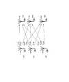
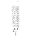
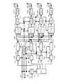
図1は、送信アンテナ数2、受信アンテナ数2、送信変調信号(送信ストリーム)数2のときの送受信装置の構成の一例を示している。送信装置では、符号化されたデータをインタリーブし、インタリーブ後のデータを変調し、周波数変換等を行い送信信号が生成され、送信信号はアンテナから送信される。このとき、送信アンテナからそれぞれ異なる変調信号が同一時刻に同一周波数に送信する方式が空間多重MIMO方式である。 FIG. 1 shows an example of the configuration of a transmission / reception apparatus when the number of transmission antennas is 2, the number of reception antennas is 2, and the number of transmission modulation signals (transmission streams) is 2. The transmitting apparatus interleaves the encoded data, modulates the interleaved data, performs frequency conversion and the like, generates a transmission signal, and transmits the transmission signal from the antenna. At this time, a method in which different modulation signals are transmitted from a transmitting antenna at the same time and at the same frequency is a spatial multiplexing MIMO method.
このとき、特許文献1では送信アンテナごとに異なるインタリーブパターンを具備する送信装置が提案されている。つまり、図1の送信装置において2つのインタリーブ(πa、πb)が互いに異なるインタリーブパターンを有していることになる。そして、受信装置において、非特許文献1、非特許文献2に示されているように、ソフト値を用いた検波方法(図1におけるMIMO detector)を、反復して行うことによって、受信品質が向上することになる。 At this time,
ところで、無線通信における実伝搬環境のモデルとして、レイリーフェージング環境で代表されるNLOS(non−line of sight)環境、ライスフェージング環境で代表されるLOS(line of sight)環境が存在する。送信装置においてシングルの変調信号を送信し、受信装置において複数のアンテナで受信した信号に対して最大比合成を行い、最大比合成後の信号に対して復調、及び復号を行う場合、LOS環境、特に、散乱波の受信電力に対する直接波の受信電力の大きさを示すライスファクタが大きい環境では、良好な受信品質を得ることができる。しかし、伝送方式(例えば、空間多重MIMO伝送方式)によっては、ライスファクタが大きくなると受信品質が劣化するという問題が発生する。(非特許文献3参照)。 By the way, as a model of an actual propagation environment in wireless communication, an NLOS (non-line of sight) environment represented by a Rayleigh fading environment and an LOS (line of sight) environment represented by a rice fading environment exist. When transmitting a single modulated signal in a transmitting device, performing maximum ratio combining on signals received by a plurality of antennas in a receiving device, and performing demodulation and decoding on a signal after the maximum ratio combining, an LOS environment; Particularly in an environment where the rice factor indicating the magnitude of the received power of the direct wave with respect to the received power of the scattered wave is large, good reception quality can be obtained. However, depending on the transmission method (for example, the spatial multiplexing MIMO transmission method), a problem occurs that the reception quality is deteriorated when the Rice factor is increased. (See Non-Patent Document 3).
図2の(A)(B)は、レイリ−フェージング環境、及びライスファクタK=3、10、16dBのライスフェージング環境において、LDPC(low−density parity−check)符号化されたデータを2×2(2アンテナ送信、2アンテナ受信)空間多重MIMO伝送した場合のBER(Bit Error Rate)特性(縦軸:BER、横軸:SNR(signal−to−noise power ratio))のシミュレーション結果の一例を示している。図2の(A)は、反復検波を行わないMax−log−APP(非特許文献1、非特許文献2参照)(APP:a posterior probability)のBER特性、図2の(B)は、反復検波を行ったMax−log−APP(非特許文献1、非特許文献2参照)(反復回数5回)のBER特性を示している。図2(A)(B)からわかるように、反復検波を行う、または行わないに関係なく、空間多重MIMOシステムでは、ライスファクタが大きくなると受信品質が劣化することが確認できる。このことから、「空間多重MIMOシステムでは、伝搬環境が安定的になると受信品質が劣化する」という従来のシングルの変調信号を送信するシステムにはない、空間多重MIMOシステム固有の課題をもつことがわかる。 FIGS. 2A and 2B show 2 × 2 LDPC (low-density parity-check) encoded data in a Rayleigh-fading environment and a Rice fading environment with a Rice factor of K = 3, 10, and 16 dB. An example of simulation results of BER (Bit Error Rate) characteristics (vertical axis: BER, horizontal axis: SNR (signal-to-noise power ratio)) in the case of (two-antenna transmission, two-antenna reception) spatial multiplexing MIMO transmission is shown. ing. FIG. 2A is a BER characteristic of Max-log-APP (APP: a posterior probability) without performing repetitive detection (APP: a posterior probability), and FIG. The BER characteristic of Max-log-APP (see
放送やマルチキャスト通信では、放送局、基地局が、多数の端末に同時に情報を伝送するため、いろいろな伝播環境に対応しなければならないサービスであり、ユーザが所持する受信機と放送局との間の電波伝搬環境はLOS環境であることは当然ありうる。前述の課題をもつ空間多重MIMOシステムを、放送やマルチキャスト通信に用いた場合、受信機において、電波の受信電界強度は高いが、受信品質の劣化によりサービスを受けることができない、という現象が発生する可能性がある。つまり、空間多重MIMOシステムを放送やマルチキャスト通信で用いるには、NLOS環境、及びLOS環境のいずれの場合においても、ある程度の受信品質が得られるMIMO伝送方式の開発が望まれる。 In broadcasting and multicast communication, broadcasting stations and base stations transmit information to a large number of terminals at the same time, so this service must cope with various propagation environments. Of course, the radio wave propagation environment of the LOS environment may be an LOS environment. When the spatial multiplexing MIMO system having the above-mentioned problem is used for broadcasting or multicast communication, a phenomenon occurs in which a receiver cannot receive a service due to deterioration of reception quality, although the electric field strength of radio waves is high. there is a possibility. In other words, in order to use the spatial multiplexing MIMO system for broadcasting and multicast communication, it is desired to develop a MIMO transmission method that can obtain a certain level of reception quality in both the NLOS environment and the LOS environment.
非特許文献4では、通信相手からのフィードバック情報からプリコーディングに用いるコードブック(プリコーディング行列(プリコーディングウェイト行列ともいう))を選択する方法について述べられているが、上記のように、放送やマルチキャスト通信のように、通信相手からのフィードバック情報が得られない状況において、プリコーディングを行う方法については全く記載されていない。
一方、非特許文献5では、フィードバック情報が無い場合にも適用することができる、時間とともに、プリコーディング行列を切り替える方法について述べられている。この文献では、プリコーディングに用いる行列として、ユニタリ行列を用いること、また、ユニタリ行列をランダムに切り替えることについて述べられているが、上記で示したLOS環境での受信品質の劣化に対する適用方法については全く記載されていなく、単にランダムに切り替えることのみが記載されている。当然であるが、LOS環境の受信品質の劣化を改善するためのプリコーディング方法、および、プリコーディング行列の構成方法に関する記述は一切されていない。 On the other hand, Non-Patent
非特許文献5に対し、特許文献2では、2つのストリームに対しプリコーディングを施し、2つのアンテナから変調信号を送信する場合において、具体的なプリコーディング行列の変更方法について説明している。 In contrast to
しかしながら、上記いずれの文献にも、3つのストリーム以上に対し、プリコーディングを施し、3つ以上のアンテナから変調信号を送信する場合において、具体的なプリコーディング行列の変更方法については記載されていない。 However, none of the above documents describes a specific method of changing a precoding matrix when precoding is performed on three or more streams and modulated signals are transmitted from three or more antennas. .
本発明は、3以上のストリームに対し、プリコーディングを施し、3つ以上のアンテナから変調信号を送信する場合に、LOS環境における受信品質の劣化を改善することができる送信装置および受信装置を提供することを目的とする。 The present invention provides a transmission device and a reception device that can improve reception quality degradation in an LOS environment when precoding is performed on three or more streams and modulated signals are transmitted from three or more antennas. The purpose is to do.
本発明に係る送信装置は、第1から第4ストリームの変調信号に対して、予め定められた固定のプリコーディング行列を用いて重み付け合成を行い、前記第1から第4ストリームの送信信号を生成する重み付け合成部と、M(Mは2以上の整数)個の位相変更値及び位相変更量ゼロから、重複を含む順列によって選択された位相変更量を用いて、位相変更対象の前記第2から前記第4ストリームの送信信号の位相をシンボル毎に変更する位相変更部と、前記第1ストリームの送信信号及び前記シンボル毎に位相変更された前記第2から前記第4ストリームの送信信号を、それぞれ、第1から第4の送信アンテナのそれぞれから送信する送信部と、を具備し、前記位相変更部は、前記位相変更対象の前記第2から前記第4ストリームの送信信号のうち、少なくとも1つの送信信号に対して、前記位相変更量ゼロを使用せず、前記M個の位相変更値のそれぞれをMシンボル連続使用して、M×M個のシンボルを連続して位相変更する、構成を採る。
The transmitting apparatus according to the present invention performs weighted synthesis on the modulated signals of the first to fourth streams using a predetermined fixed precoding matrix to generate the first to fourth stream transmission signals. A weighting synthesis unit that performs the phase change from the second phase change target using M (M is an integer of 2 or more) phase change values and a phase change amount of zero using a phase change amount selected by a permutation including overlap. A phase change unit that changes the phase of the transmission signal of the fourth stream for each symbol, and the transmission signal of the first stream and the transmission signal of the second to fourth streams whose phase is changed for each symbol, ,comprising a transmission unit from a first transmitted from each of the fourth transmitantennas, wherein the phase changing portion, the transmission signal of the fourth stream from said second of said phase change target Of these, for at least one transmission signal, the phase change amount is not used, and the M phase change values are used continuously for M symbols, and M × M symbols are continuously phase changed. Take the configuration.
本発明によれば、3以上のストリームに対し、プリコーディングを施した場合に、LOS環境における受信品質の劣化を改善することができるため、放送やマルチキャスト通信において見通し内のユーザに対して、品質の高いサービスを提供することができる。 According to the present invention, when precoding is performed on three or more streams, it is possible to improve reception quality degradation in an LOS environment. Service can be provided.
以下、本発明の実施の形態について図面を参照して詳細に説明する。 Hereinafter, embodiments of the present invention will be described in detail with reference to the drawings.
(実施の形態1)
本実施の形態の送信方法、送信装置、受信方法、受信装置について詳しく説明する。(Embodiment 1)
The transmission method, the transmission device, the reception method, and the reception device of the present embodiment will be described in detail.
本説明を行う前に、従来システムである空間多重MIMO伝送システムにおける、送信方法、復号方法の概要について説明する。 Prior to the description, an outline of a transmission method and a decoding method in a spatial multiplexing MIMO transmission system which is a conventional system will be described.
NtxNr空間多重MIMOシステムの構成を図3に示す。情報ベクトルzは、符号化およびインタリーブが施される。そして、インタリーブの出力として、符号化後ビットのベクトルu=(u1,…,uNt)が得られる。ただし、ui=(ui1,…,uiM)とする(M:シンボル当たりの送信ビット数)。送信ベクトルs=(s1,…,sNt)Tとすると送信アンテナ#iから送信信号si=map(ui)とあらわし、送信エネルギーを正規化するとE{|si|2}=Es/Ntとあらわされる(Es:チャネル当たりの総エネルギー)。そして、受信ベクトルをy=(y1,…,yNr)Tとすると、式(1)のようにあらわされる。
このとき、HNtNrはチャネル行列、n=(n1,…,nNr)Tはノイズベクトルであり、niは平均値0、分散σ2のi.i.d.複素ガウス雑音である。受信機で導入する送信シンボルと受信シンボルの関係から、受信ベクトルに関する確率は、式(2)のように多次元ガウス分布で与えることができる。
ここで、outer soft−in/soft−outデコーダとMIMO検波からなる図3のような反復復号を行う受信機を考える。図1における対数尤度比のベクトル(L−value)は式(3)−(5)のようにあらわされる。
<反復検波方法>
ここでは、NtxNr空間多重MIMOシステムにおけるMIMO信号の反復検波について述べる。<Iterative detection method>
Here, we describe MIMO signal iterative detection in N t xNr spatial multiplexing MIMO system.
xumnの対数尤度比を式(6)のように定義する。
ベイズの定理より、式(6)は、式(7)のようにあらわすことができる。
ただし、Umn,±1={u|umn=±1}とする。そして、lnΣaj〜max ln ajで近似すると式(7)は式(8)のように近似することができる。なお、上の「〜」の記号は近似を意味する。
式(8)におけるP(u|umn)とln P(u|umn)は以下の式(9)、(10)、(11)のようにあらわされる。
ところで、式(2)で定義した式の対数確率は式(12)のようにあらわされる。
したがって、式(7),(12)から、MAP、または、APP(a posteriori probability)では、事後のL−valueは、以下の式(13)ようにあらわされる。
以降では、反復APP復号と呼ぶ。また、式(8),(12)から、Max−Log近似に基づく対数尤度比(Max−Log APP)では、事後のL−valueは、以下の式(14)のようにあらわされる。
以降では、反復Max−log APP復号と呼ぶ。そして、反復復号のシステムで必要とする外部情報は、式(13)または(14)から事前入力を減算することで、求めることができる。 Hereinafter, it is referred to as iterative Max-log APP decoding. The external information required by the iterative decoding system can be obtained by subtracting the prior input from the equation (13) or (14).
<システムモデル>
図1に、以降の説明につながるシステムの基本構成を示す。ここでは、2×2空間多重MIMOシステムとし、ストリームA,Bではそれぞれにouterエンコーダがあり、2つのouterエンコーダは同一のLDPC符号のエンコーダとする(ここではouterエンコーダとしてLDPC符号のエンコーダを用いる構成を例に挙げて説明するが、outerエンコーダが用いる誤り訂正符号はLDPC符号に限ったものではなく、ターボ符号、畳み込み符号、LDPC畳み込み符号等の他の誤り訂正符号を用いても同様に実施することができる。また、outerエンコーダは、送信アンテナごとに有する構成としているがこれに限ったものではなく、送信アンテナが複数であっても、outerエンコーダは一つであってもよく、また、送信アンテナ数より多くのouterエンコーダを有していてもよい。)。そして、ストリームA,Bではそれぞれにインタリーバ(πa,πb)がある。ここでは、変調方式を2h−QAMとする(1シンボルでhビットを送信することになる。)。<System model>
FIG. 1 shows a basic configuration of a system leading to the following description. Here, a 2 × 2 spatial multiplexing MIMO system is used, and each of the streams A and B has an outer encoder. The two outer encoders are encoders of the same LDPC code (here, an encoder using an LDPC code encoder as the outer encoder). However, the error correction code used by the outer encoder is not limited to the LDPC code, and the same applies to other error correction codes such as a turbo code, a convolutional code, and an LDPC convolutional code. Further, the outer encoder has a configuration provided for each transmission antenna, but is not limited to this, and there may be a plurality of transmission antennas or a single outer encoder. With more outer encoders than antennas Even if it is.). The streams A and B have interleavers (πa , πb ), respectively. Here, the modulation scheme is 2h -QAM (h bits are transmitted in one symbol).
受信機では、上述のMIMO信号の反復検波(反復APP(またはMax−log APP)復号)を行うものとする。そして、LDPC符号の復号としては、例えば、sum−product復号を行うものとする。 The receiver performs iterative detection (iterative APP (or Max-log APP) decoding) of the MIMO signal described above. As decoding of the LDPC code, for example, sum-product decoding is performed.
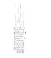
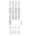
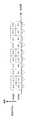
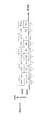
図4はフレーム構成を示しており、インタリーブ後のシンボルの順番を記載している。このとき、以下の式(16)、(17)のように(ia,ja),(ib,jb)をあらわすものとする。
このとき、ia,ib:インタリーブ後のシンボルの順番、ja,jb:変調方式におけるビット位置(ja,jb=1,・・・,h)、πa,πb:ストリームA,Bのインタリーバ、Ωaia,ja,Ωbib,jb:ストリームA,Bのインタリーブ前のデータの順番、を示している。ただし、図4では、ia=ibのときのフレーム構成を示している。At thistime,ia, ib: The order of symbols afterinterleaving,ja, jb: bit positions in the modulation scheme(j a, j b = 1 , ···, h), π a, π b: Stream a, B of theinterleaver, Ω a ia, ja, Ω b ib, jb: stream a, indicate the order of the data before interleaving B. However, FIG. 4shows a frame structure wheni a = ib.
<反復復号>
ここでは、受信機におけるLDPC符号の復号で用いるsum−product復号およびMIMO信号の反復検波のアルゴリズムについて詳しく述べる。<Iterative decoding>
Here, the algorithm of sum-product decoding and iterative detection of a MIMO signal used in decoding of an LDPC code in a receiver will be described in detail.
sum−product復号
2元MxN行列H={Hmn}を復号対象とするLDPC符号の検査行列とする。集合[1,N]={1,2,・・・,N}の部分集合A(m),B(n)を以下の式(18)、(19)のように定義する。
このとき、A(m)は検査行列Hのm行目において、1である列インデックスの集合を意味し、B(n)は検査行列Hのn行目において1である行インデックスの集合である。sum−product復号のアルゴリズムは以下のとおりである。 At this time, A (m) is a set of column indices of 1 in the m-th row of the parity check matrix H, and B (n) is a set of row indices of 1 in the n-th row of the parity check matrix H. . The algorithm of sum-product decoding is as follows.
Step A・1(初期化):Hmn=1を満たす全ての組(m,n)に対して事前値対数比βmn=0とする。ループ変数(反復回数)lsum=1とし、ループ最大回数をlsum,maxと設定する。Step A · 1 (initialization): Prior value log ratio βmn = 0 for all sets (m, n) that satisfy Hmn = 1. The loop variable (the number of iterations) lsum = 1, and the maximum number of loops is set as lsum, max .
Step A・2(行処理):m=1,2,・・・,Mの順にHmn=1を満たす全ての組(m,n)に対して、以下の更新式(20)、(21)、(22)を用いて外部値対数比αmnを更新する。
このとき、fはGallagerの関数である。そして、λnの求め方については以降で詳しく説明する。At this time, f is a function of Gallager. The method for obtaining λn will be described later in detail.
Step A・3(列処理):n=1,2,・・・,Nの順にHmn=1を満たす全ての組(m,n)に対して、以下の更新式(23)を用いて外部値対数比βmnを更新する。
Step A・4(対数尤度比の計算):n∈[1,N]について対数尤度比Lnを以下の式(24)のように求める。
Step A・5(反復回数のカウント):もしlsum<lsum,maxならばlsumをインクリメントして、step A・2に戻る。lsum=lsum,maxの場合、この回のsum−product復号は終了する。Step A · 5 (count of the number of repetitions): If lsum <lsum, max , increment lsum and return to step A · 2. If lsum = lsum, max , the current sum-product decoding ends.
以上が、1回のsum−product復号の動作である。その後、MIMO信号の反復検波が行われる。上述のsum−product復号の動作の説明で用いた変数m,n,αmn,βmn,λn,Lnにおいて、ストリームAにおける変数をma,na,αamana,βamana,λna,Lna、ストリームBにおける変数をmb,nb,αbmbnb,βbmbnb,λnb,Lnbであらわすものとする。The above is the operation of one sum-product decoding. After that, iterative detection of the MIMO signal is performed. Variable m used in the description of the operation of the aforementioned sum-productdecoding, n, α mn, β mn , at λn, Ln, the variables in the streamA m a, n a, α a mana, β a mana, λna, Lna, variablesm b in the streamB, n b, α b mbnb , β b mbnb, λ nb, shall be represented byL nb.
<MIMO信号の反復検波>
ここでは、MIMO信号の反復検波におけるλnの求め方について詳しく説明する。<Repeated detection of MIMO signal>
Here, it will be described in detail how to determine the lambdan in MIMO signal iterative detection.
式(1)から、次の式(25)が成立する。
図4のフレーム構成からと、式(16)(17)から、以下の関係式が成立する。
このとき、na,nb∈[1,N]となる。以降では、MIMO信号の反復検波の反復回数kのときのλna,Lna,λnb,Lnbをそれぞれλk,na,Lk,na,λk,nb,Lk,nbとあらわすものとする。At this time, na , nb ∈ [1, N]. Hereinafter, λna , Lna , λnb , and Lnb when the number of repetitions of the repetitive detection of the MIMO signal isk are represented as λk, na , Lk, na , λk, nb , Lk, nb , respectively. And
Step B・1(初期検波;k=0):初期検波のとき、λ0,na,λ0,nbを以下の式(28)、(29)、(30)のように求める。
反復APP復号のとき:
For iterative APP decoding:
反復Max−log APP復号のとき:
ただし、X=a,bとする。そして、MIMO信号の反復検波の反復回数をlmimo=0とし、反復回数の最大回数をlmimo,maxと設定する。Note that X = a, b. Then, the number of repetitions of the repetitive detection of the MIMO signal is set to lmimo = 0, and the maximum number of repetitions is set to lmimo, max .
Step B・2(反復検波;反復回数k):反復回数kのときのλk,na,λk,nbは、式(11)(13)−(15)(16)(17)から式(31)−(34)のようにあらわされる。ただし、(X,Y)=(a,b)(b,a)となる。Step B · 2 (iteration detection; number of repetitions k): λk, na , λk, nb at the time of the number of repetitions k is calculated from the equations (11) (13)-(15) (16) (17) from the equation (17). 31)-(34). However, (X, Y) = (a, b) (b, a).
反復APP復号のとき:
反復Max−log APP復号のとき:
Step B・3(反復回数のカウント、符号語推定):もしlmimo<lmimo,maxならばlmimoをインクリメントして、step B・2に戻る。lmimo=lmimo,maxの場合、推定符号語を以下の式(35)のようにもとめる。
ただし、X=a,bとする。 Note that X = a, b.
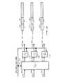
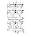
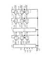
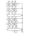
図5は、本実施の形態における送信装置の構成の一例である。符号化器502Aは、情報(データ)501A、フレーム構成信号513を入力とし、フレーム構成信号513(符号化器502Aがデータの誤り訂正符号化に使用する誤り訂正方式、符号化率、ブロック長等の情報が含まれており、フレーム構成信号513が指定した方式を用いることになる。また、誤り訂正方式は、切り替えても良い。)にしたがい、例えば、畳み込み符号、LDPC符号、ターボ符号等の誤り訂正符号化を行い、符号化後のデータ503Aを出力する。 FIG. 5 is an example of the configuration of the transmitting apparatus according to the present embodiment. The
インタリーバ504Aは、符号化後のデータ503A、フレーム構成信号513を入力とし、インタリーブ、つまり、順番の並び替えを行い、インタリーブ後のデータ505Aを出力する。(フレーム構成信号513に基づき、インタリーブの方法は、切り替えても良い。)
マッピング部506Aは、インタリーブ後のデータ505A、フレーム構成信号513を入力とし、QPSK(Quadrature Phase Shift Keying)、16QAM(16 Quadrature Amplitude Modulation)、64QAM(64 Quadrature Amplitude Modulation)等の変調を施し、ベースバンド信号507Aを出力する。(フレーム構成信号513に基づき、変調方式は、切り替えても良い。)なお、変調方式は、QPSK、16QAM、64QAMに限ったものではなく、非均一のマッピングを行ってもよい。つまり、同相I−直交Q平面において、複数の信号点が存在していればよい。 The
図7は、QPSK変調におけるベースバンド信号を構成する同相成分Iと直交成分QのIQ平面におけるマッピング方法の一例としている。例えば、図7(A)のように、入力データが「00」の場合、I=1.0、Q=1.0が出力され、以下同様に、入力データが「01」の場合、I=―1.0、Q=1.0が出力され、・・・、が出力される。図7(B)は、図7(A)とは異なるQPSK変調のIQ平面におけるマッピング方法の例であり、図7(B)が図7(A)と異なる点は、図7(A)における信号点が、原点を中心に回転させることで図7(B)の信号点を得ることができる。このようなコンスタレーションの回転方法については、非特許文献6、非特許文献7に示されており、また、非特許文献6、非特許文献7に示されているCyclic Q Delayを適用してもよい。 FIG. 7 shows an example of a mapping method of an in-phase component I and a quadrature component Q constituting a baseband signal in QPSK modulation on an IQ plane. For example, as shown in FIG. 7A, when the input data is "00", I = 1.0 and Q = 1.0 are output. Similarly, when the input data is "01", I = 1.0. −1.0, Q = 1.0 are output,... Are output. FIG. 7B is an example of a mapping method on the IQ plane of QPSK modulation different from FIG. 7A, and FIG. 7B is different from FIG. 7A in that FIG. The signal point shown in FIG. 7B can be obtained by rotating the signal point about the origin. Such a constellation rotation method is described in
図7とは別の例として、図8に16QAMのときのIQ平面における信号点配置を示しており、図7(A)に相当する例が図8(A)であり、図7(B)に相当する例が図8(B)となる。 As another example different from FIG. 7, FIG. 8 shows a signal point arrangement on the IQ plane in 16QAM, and FIG. 8 (A) shows an example corresponding to FIG. 7 (A), and FIG. FIG. 8B shows an example corresponding to.
符号化器502Bは、情報(データ)501B、フレーム構成信号513を入力とし、フレーム構成信号513(使用する誤り訂正方式、符号化率、ブロック長等の情報が含まれており、フレーム構成信号513が指定した方式を用いることになる。また、誤り訂正方式は、切り替えても良い。)にしたがい、例えば、畳み込み符号、LDPC符号、ターボ符号等の誤り訂正符号化を行い、符号化後のデータ503Bを出力する。 The
インタリーバ504Bは、符号化後のデータ503B、フレーム構成信号513を入力とし、インタリーブ、つまり、順番の並び替えを行い、インタリーブ後のデータ505Bを出力する。(フレーム構成信号513に基づき、インタリーブの方法は、切り替えても良い。)なお、変調方式は、QPSK、16QAM、64QAMに限ったものではなく、非均一のマッピングを行ってもよい。つまり、同相I−直交Q平面において、複数の信号点が存在していればよい。
マッピング部506Bは、インタリーブ後のデータ505B、フレーム構成信号513を入力とし、QPSK(Quadrature Phase Shift Keying)、16QAM(16 Quadrature Amplitude Modulation)、64QAM(64 Quadrature Amplitude Modulation)等の変調を施し、ベースバンド信号507Bを出力する。(フレーム構成信号513に基づき、変調方式は、切り替えても良い。) The
符号化器502Cは、情報(データ)501C、フレーム構成信号513を入力とし、フレーム構成信号513(使用する誤り訂正方式、符号化率、ブロック長等の情報が含まれており、フレーム構成信号513が指定した方式を用いることになる。また、誤り訂正方式は、切り替えても良い。)にしたがい、例えば、畳み込み符号、LDPC符号、ターボ符号等の誤り訂正符号化を行い、符号化後のデータ503Cを出力する。 The
インタリーバ504Cは、符号化後のデータ503C、フレーム構成信号513を入力とし、インタリーブ、つまり、順番の並び替えを行い、インタリーブ後のデータ505Cを出力する。(フレーム構成信号513に基づき、インタリーブの方法は、切り替えても良い。)なお、変調方式は、QPSK、16QAM、64QAMに限ったものではなく、非均一のマッピングを行ってもよい。つまり、同相I−直交Q平面において、複数の信号点が存在していればよい。
マッピング部506Cは、インタリーブ後のデータ505C、フレーム構成信号513を入力とし、QPSK(Quadrature Phase Shift Keying)、16QAM(16 Quadrature Amplitude Modulation)、64QAM(64 Quadrature Amplitude Modulation)等の変調を施し、ベースバンド信号507Cを出力する。(フレーム構成信号513に基づき、変調方式は、切り替えても良い。) The
信号処理方法情報生成部514は、フレーム構成信号513を入力とし、フレーム構成信号513に基づいた信号処理方法に関する情報515を出力する。なお、信号処理方法に関する情報515は、どのプリコーディング行列を固定的に用いるのかを指定する情報と、位相を変更する位相変更パターンの情報を含む。 The signal processing method
重み付け合成部508Aは、ベースバンド信号507A、ベースバンド信号507B、ベースバンド信号507C、信号処理方法に関する情報515を入力とし、信号処理方法に関する情報515に基づいて、ベースバンド信号507Aおよびベースバンド信号507Bおよびベースバンド信号507Cに対し重み付け合成を施し、重み付け合成後の信号516Aを出力する。なお、重み付け合成の方法の詳細については、後で詳しく説明する。 The
位相変更部517Aは、重み付け合成後の信号516A及び信号処理方法に関する情報515を入力とし、当該信号516Aの位相を規則的に変更して出力する。規則的に変更するとは、予め定められた周期(例えば、n個のシンボル毎(nは1以上の整数)あるいは予め定められた時間毎、あるいは予め定められた周波数毎)で、予め定められた位相変更パターンに従って位相を変更する。位相変更パターンの詳細については、後で説明する。(なお、位相変更を行わなくてもよい。) The
無線部510Aは、位相変更後の信号509Aを入力とし、直交変調、帯域制限、周波数変換、増幅等の処理を施し、送信信号511Aを出力し、送信信号511Aは、アンテナ512Aから電波として出力される。
重み付け合成部508Bは、ベースバンド信号507A、ベースバンド信号507B、ベースバンド信号507C、信号処理方法に関する情報515を入力とし、信号処理方法に関する情報515に基づいて、ベースバンド信号507Aおよびベースバンド信号507Bおよびベースバンド信号507Cに対し重み付け合成を施し、重み付け合成後の信号512Bを出力する。なお、重み付け合成の方法の詳細については、後で詳しく説明する。 The weighting /
位相変更部517Bは、重み付け合成後の信号516B及び信号処理方法に関する情報515を入力とし、当該信号516Bの位相を規則的に変更して出力する。規則的に変更するとは、予め定められた周期(例えば、n個のシンボル毎(nは1以上の整数)あるいは予め定められた時間毎)で、予め定められた位相変更パターンに従って位相を変更する。位相変更パターンの詳細については、後で説明する。(なお、位相変更を行わなくてもよい。) The
無線部510Bは、位相変更後の信号509Bを入力とし、直交変調、帯域制限、周波数変換、増幅等の処理を施し、送信信号511Bを出力し、送信信号511Bは、アンテナ512Bから電波として出力される。
重み付け合成部508Cは、ベースバンド信号507A、ベースバンド信号507B、ベースバンド信号507C、信号処理方法に関する情報515を入力とし、信号処理方法に関する情報515に基づいて、ベースバンド信号507Aおよびベースバンド信号507Bおよびベースバンド信号507Cに対し重み付け合成を施し、重み付け合成後の信号512Cを出力する。なお、重み付け合成の方法の詳細については、後で詳しく説明する。 The weighting synthesis unit 508C receives the
位相変更部517Cは、重み付け合成後の信号516C及び信号処理方法に関する情報515を入力とし、当該信号516Cの位相を規則的に変更して出力する。規則的に変更するとは、予め定められた周期(例えば、n個のシンボル毎(nは1以上の整数)あるいは予め定められた時間毎)で、予め定められた位相変更パターンに従って位相を変更する。位相変更パターンの詳細については、後で説明する。(なお、位相変更を行わなくてもよい。) The
無線部510Cは、位相変更後の信号509Cを入力とし、直交変調、帯域制限、周波数変換、増幅等の処理を施し、送信信号511Cを出力し、送信信号511Cは、アンテナ512Cから電波として出力される。
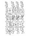
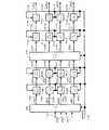
図9に重み付け合成部(508A、508B、508C)および位相変更部(517A、517B、517C)の構成を示す。図9において点線で囲まれる領域が重み付け合成部となり、重み付け合成部の後段が位相変更部となる。なお、図9の重み付け合成部は、図5の重み付け合成部508A、重み付け合成部508B、重み付け合成部508Cをあわせて記載している。そして、図9の位相変更部は、図5の位相変更部517A、位相変更部517B、位相変更部517Cをあわせて記載している。 FIG. 9 shows the configurations of the weighting synthesis units (508A, 508B, 508C) and the phase change units (517A, 517B, 517C). In FIG. 9, a region surrounded by a dotted line is a weighting synthesis unit, and a stage subsequent to the weighting synthesis unit is a phase changing unit. Note that the weighting / synthesizing unit in FIG. 9 includes the weighting /
ベースバンド信号507Aはw11と乗算し、w11×s1(t)が生成され、ベースバンド信号507Aはw21と乗算し、w21×s1(t)が生成され、ベースバンド信号507Aはw31と乗算し、w31×s1(t)が生成される。The
同様に、ベースバンド信号507Bはw12と乗算し、w12×s2(t)が生成され、ベースバンド信号507Bはw22と乗算し、w22×s2(t)が生成され、ベースバンド信号507Bはw32と乗算し、w32×s2(t)が生成される。Similarly, the
同様に、ベースバンド信号507Cはw13と乗算し、w13×s3(t)が生成され、ベースバンド信号507Cはw23と乗算し、w23×s3(t)が生成され、ベースバンド信号507Cはw33と乗算し、w33×s3(t)が生成される。Similarly, the
このとき、s1(t)およびs2(t)およびs3(t)は、上記の説明からわかるように、BPSK(Binary Phase Shift Keying)、QPSK、8PSK(8 Phase Shift Keying)、16QAM、32QAM(32 Quadrature Amplitude Modulation)、64QAM、256QAM、16APSK(16 Amplitude Phase Shift Keying)等の変調方式のベースバンド信号(マッピング後のベースバンド信号)となる。At this time, s1 (t), s2 (t), and s3 (t) are BPSK (Binary Phase Shift Keying), QPSK, 8PSK (8 Phase Shift Keying), 16QAM, A baseband signal (baseband signal after mapping) of a modulation method such as 32QAM (32 Quadrature Amplitude Modulation), 64QAM, 256QAM, and 16APSK (16 Amplitude Phase Shift Keying).
ここで、重み付け合成部は、例えば、固定のプリコーディング行列を用いて重み付けを実行するものとする。このとき、プリコーディング行列は、以下の式(36)のようにあらわすものとする。
ただし、a11は複素数であり(実数でもよい)、a12は複素数であり(実数でもよい)、a13は複素数であり(実数でもよい)、a21は複素数であり(実数でもよい)、a22は複素数であり(実数でもよい)、a23は複素数であり(実数でもよい)、a31は複素数であり(実数でもよい)、a32は複素数であり(実数でもよい)、a33は複素数である(実数でもよい)。したがって、axy=Axyejδxyとあらわされることになる。(ただし、jは虚数単位であり、Axyは0以上の実数、δxyは偏角 (argument)となる。また、xは1、2、3のいずれの値でもよく、yは1、2、3のいずれの値でもよい。)Here, a11 is a complex number (may be a real number), a12 is a complex number (may be a real number), a13 is a complex number (may be a real number), a21 is a complex number (may be a real number), a22 is a complex number (may be a real number), a23 is a complex number (may be a real number), a31 is a complex number (may be a real number), a32 is a complex number (may be a real number), and a33 Is a complex number (it may be a real number).Therefore, it would be represented asaxy = A xye jδxy. (Where j is an imaginary unit, Axy is a real number equal to or greater than 0, δxy is an argument. X may be any value of 1, 2, or 3, and y may be 1 or 2. , Any of 3)
そして、a11、a12、a13のすべてが0(ゼロ)となることはなく、a21、a22、a23のすべてが0(ゼロ)となることはなく、a31、a32、a33のすべてが0(ゼロ)となることはない。また、a11、a21、a31のすべてが0(ゼロ)となることはなく、a12、a22、a32のすべてが0(ゼロ)となることはなく、a13、a23、a33のすべてが0(ゼロ)となることはない。Then, all of a11 , a12 , and a13 do not become 0 (zero), all of a21 , a22 , and a23 do not become 0 (zero), and a31 , a32 , Not all of a33 become 0 (zero). Further, all of a11 , a21 , and a31 do not become 0 (zero), all of a12 , a22 , and a32 do not become 0 (zero), and a13 , a23 , Not all of a33 become 0 (zero).
したがって、図9において、重み付け合成後(プリコーディング後)の信号をz1’(t)(図5の516Aに相当)、z2’(t)(図5の516Bに相当)、z3’(t)(図5の516Cに相当)としたとき、次式(37)が成立する。
なお、プリコーディング行列は、変調方式(または、変調方式のセット(図5の場合、3つの変調方式のセット))、誤り訂正符号化方式(例えば、使用する誤り訂正符号、誤り訂正符号の符号長(ブロック長)、誤り訂正符号の符号化率)などにより、プリコーディング行列を切り替えてもよい。 The precoding matrix includes a modulation scheme (or a set of modulation schemes (in FIG. 5, a set of three modulation schemes)) and an error correction coding scheme (for example, an error correction code to be used, a code of an error correction code, The precoding matrix may be switched depending on the length (block length), the coding rate of the error correction code, and the like.
また、上述の例では、プリコーディング行列を固定のプリコーディング行列を例に説明したが、これに限ったものではなく、プリコーディング行列を例えば時間によって、切り替えてもよい。このとき、プリコーディング行列は、次式(38)であらわされる。
ただし、a11(t)は複素数であり(実数でもよい)、a12(t)は複素数であり(実数でもよい)、a13(t)は複素数であり(実数でもよい)、a21(t)は複素数であり(実数でもよい)、a22(t)は複素数であり(実数でもよい)、a23(t)は複素数であり(実数でもよい)、a31(t)は複素数であり(実数でもよい)、a32(t)は複素数であり(実数でもよい)、a33(t)は複素数である(実数でもよい)。したがって、axy(t)=Axy(t)ejδxy(t)とあらわされることになる。(ただし、jは虚数単位であり、Axy(t)は0以上の実数、δxy(t)は偏角 (argument)となる。また、xは1、2、3のいずれの値でもよく、yは1、2、3のいずれの値でもよい。)Here, a11 (t) is a complex number (it may be a real number), a12 (t) is a complex number (it may be a real number), a13 (t) is a complex number (it may be a real number), and a21 ( t) is a complex number (may be a real number), a22 (t) is a complex number (may be a real number), a23 (t) is a complex number (may be a real number), and a31 (t) is a complex number. Yes (may be a real number), a32 (t) is a complex number (may be a real number), and a33 (t) is a complex number (may be a real number). Therefore, it is expressed as axy (t) = Axy (t) ejδxy (t) . (Where j is an imaginary unit, Axy (t) is a real number equal to or greater than 0, δxy (t) is an argument. X may be any value of 1, 2, or 3. , Y may be any value of 1, 2, and 3.)
そして、a11(t)、a12(t)、a13(t)のすべてが0(ゼロ)となることはなく、a21(t)、a22(t)、a23(t)のすべてが0(ゼロ)となることはなく、a31(t)、a32(t)、a33(t)のすべてが0(ゼロ)となることはない。また、a11(t)、a21(t)、a31(t)のすべてが0(ゼロ)となることはなく、a12(t)、a22(t)、a32(t)のすべてが0(ゼロ)となることはなく、a13(t)、a23(t)、a33(t)のすべてが0(ゼロ)となることはない。Then, all of a11 (t), a12 (t), and a13 (t) do not become 0 (zero), and a21 (t), a22 (t), and a23 (t) Not all become 0 (zero), and all of a31 (t), a32 (t), and a33 (t) do not become 0 (zero). Further, all of a11 (t), a21 (t), and a31 (t) do not become 0 (zero), and a12 (t), a22 (t), and a32 (t) All of them do not become 0 (zero), and all of a13 (t), a23 (t), and a33 (t) do not become 0 (zero).
なお、式(38)では、時間tの関数としているが、これに限ったものではなく、周波数(キャリア)fの関数であってもよいし、時間tおよび周波数(キャリア)fの両者の関数であってもよい。(これらに限ったものではない。) In equation (38), the function of the time t is used. However, the function is not limited to this, and may be a function of the frequency (carrier) f, or a function of both the time t and the frequency (carrier) f. It may be. (Not limited to these.)
図9に示すように、重み付け合成後(プリコーディング後)の信号z1’(t)(図5の516Aに相当)、は位相変更が行われ、位相変更後の信号(図5の509Aに相当)z1(t)を得ることになる。このとき、位相変更値をy1(t)とすると、位相変更後の信号(図5の509Aに相当)z1(t)は次式(39)であらわされる。
このとき、y1(t)はB1×ejθ1(t)、または、ejθ1(t)とあらわすものとする。B1は0以上の実数であり、θ1(t)は偏角 (argument)となり、時間tの関数であるものとする。ただし、θ1は時間tの関数に限ったものではなく、周波数(キャリア)fの関数であってもよいし、時間tおよび周波数(キャリア)fの関数であってもよい。(これに限ったものではない。)At this time, y1 (t) is represented by B1 × ejθ1 (t) or ejθ1 (t) . B1 is a real number equal to or greater than 0, and θ1 (t) is an argument and is a function of time t. However, θ1 is not limited to the function of the time t, and may be a function of the frequency (carrier) f or a function of the time t and the frequency (carrier) f. (Not limited to this.)
y1(t)は、規則的に変更することになる。なお、規則的に変更するとは、予め定められた周期(例えば、n個のシンボル毎(nは1以上の整数)あるいは予め定められた時間毎)で、予め定められた位相変更パターンに従って位相を変更する。位相変更パターンの詳細については、後で説明する。(なお、位相変更を行わなくてもよい。)y1 (t) will be changed regularly. It should be noted that to change regularly means that the phase is changed in accordance with a predetermined phase change pattern at a predetermined cycle (for example, at every n symbols (n is an integer of 1 or more) or at a predetermined time). change. Details of the phase change pattern will be described later. (Note that it is not necessary to change the phase.)
図9に示すように、重み付け合成後(プリコーディング後)の信号z2’(t)(図5の516Bに相当)、は位相変更が行われ、位相変更後の信号(図5の509Bに相当)z2(t)を得ることになる。このとき、位相変更値をy2(t)とすると、位相変更後の信号(図5の509Bに相当)z2(t)は次式(40)であらわされる。
このとき、y2(t)はB2×ejθ2(t)、または、ejθ2(t)とあらわすものとする。、B2は0以上の実数であり、θ2(t)は偏角 (argument)となり、時間tの関数であるものとする。ただし、θ2は時間tの関数に限ったものではなく、周波数(キャリア)fの関数であってもよいし、時間tおよび周波数(キャリア)fの関数であってもよい。(これに限ったものではない。)At this time, y2 (t) is represented as B2 ×ejθ2 (t) orejθ2 (t) . , B2 are real numbers greater than or equal to 0, and θ2 (t) is an argument and is a function of time t. However, theta2 is not limited to the function of time t, it may be a function of frequency (carrier) f, may be a function of time t and frequency (carrier) f. (Not limited to this.)
y2(t)は、規則的に変更することになる。なお、規則的に変更するとは、予め定められた周期(例えば、n個のシンボル毎(nは1以上の整数)あるいは予め定められた時間毎)で、予め定められた位相変更パターンに従って位相を変更する。位相変更パターンの詳細については、後で説明する。(なお、位相変更を行わなくてもよい。)y2 (t) will change regularly. It should be noted that to change regularly means that the phase is changed in accordance with a predetermined phase change pattern at a predetermined cycle (for example, at every n symbols (n is an integer of 1 or more) or at a predetermined time). change. Details of the phase change pattern will be described later. (Note that it is not necessary to change the phase.)
図9に示すように、重み付け合成後(プリコーディング後)の信号z3’(t)(図5の516Cに相当)、は位相変更が行われ、位相変更後の信号(図5の509Cに相当)z3(t)を得ることになる。このとき、位相変更値をy3(t)とすると、位相変更後の信号(図5の509Cに相当)z3(t)は次式(41)であらわされる。
このとき、y3(t)はB3×ejθ3(t)、または、ejθ3(t)とあらわすものとする。B3は0以上の実数であり、θ3(t)は偏角 (argument)となり、時間tの関数であるものとする。ただし、θ3は時間tの関数に限ったものではなく、周波数(キャリア)fの関数であってもよいし、時間tおよび周波数(キャリア)fの関数であってもよい。(これに限ったものではない。)At this time, y3 (t) is represented by B3 × ejθ3 (t) or ejθ3 (t) . B3 is a real number equal to or greater than 0, and θ3 (t) is an argument and is a function of time t. However, theta3 is not limited to the function of time t, it may be a function of frequency (carrier) f, may be a function of time t and frequency (carrier) f. (Not limited to this.)
y3(t)は、規則的に変更することになる。なお、規則的に変更するとは、予め定められた周期(例えば、n個のシンボル毎(nは1以上の整数)あるいは予め定められた時間毎)で、予め定められた位相変更パターンに従って位相を変更する。位相変更パターンの詳細については、後で説明する。(なお、位相変更を行わなくてもよい。)y3 (t) will be changed regularly. It should be noted that to change regularly means that the phase is changed in accordance with a predetermined phase change pattern at a predetermined cycle (for example, at every n symbols (n is an integer of 1 or more) or at a predetermined time). change. Details of the phase change pattern will be described later. (Note that it is not necessary to change the phase.)
図6は、図5とは異なる送信装置の構成の例を示している。図6において、図5と異なる部分について説明する。 FIG. 6 illustrates an example of a configuration of a transmission device different from that of FIG. In FIG. 6, parts different from FIG. 5 will be described.
符号化器602は、情報(データ)601、フレーム構成信号513を入力とし、フレーム構成信号513に基づき、誤り訂正符号化を行い、符号化後のデータ603を出力する。
分配部604は符号化後のデータ603を入力とし、分配し、データ605Aおよびデータ605Bおよびデータ605Cを出力する。なお、図6では、符号化器が一つの場合を記載したが、これに限ったものではなく、符号化器をm(mは1以上の整数)とし、各符号化器で作成された符号化データを分配部が、3系統のデータにわけて出力する場合についても、本発明は同様に実施することができる。 The
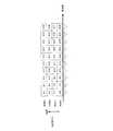
図10は、本実施の形態における送信装置の時間軸におけるフレーム構成の一例を示している。シンボル1000_1は、受信装置に、送信方法を通知するためのシンボルであり、例えば、データシンボルを伝送するために用いる誤り訂正方式、その符号化率の情報、データシンボルを伝送するために用いる変調方式の情報等を伝送する。 FIG. 10 shows an example of a frame configuration on the time axis of the transmitting apparatus according to the present embodiment. The symbol 1000_1 is a symbol for notifying the receiving apparatus of a transmission method, for example, an error correction scheme used for transmitting a data symbol, information on its coding rate, a modulation scheme used for transmitting a data symbol. And the like.
シンボル1001_1は、送信装置が送信する変調信号z1(t){ただし、tは時間}のチャネル変動を推定するためのシンボルである。シンボル1002_1は変調信号z1(t)が(時間軸における)シンボル番号uに送信するデータシンボル、シンボル1003_1は変調信号z1(t)がシンボル番号u+1に送信するデータシンボルである。Symbol 1001_1 is a symbol for estimating channel fluctuation in modulated signal z1 (t) {where, t is time} transmitted by the transmission device. Symbol 1002_1 is a data symbol modulated signalz 1 (t) is a data symbol to be sent to the symbol number u (in the time axis), the symbol
シンボル1001_2は、送信装置が送信する変調信号z2(t){ただし、tは時間}のチャネル変動を推定するためのシンボルである。シンボル1002_2は変調信号z2(t)がシンボル番号uに送信するデータシンボル、シンボル1003_2は変調信号z2(t)がシンボル番号u+1に送信するデータシンボルである。The symbol 1001_2 is a symbol for estimating a channel variation in a modulated signal z2 (t) {where, t is a time} transmitted by the transmitting apparatus. Symbol 1002_2 is a data symbol transmitted by modulated signal z2 (t) at symbol number u, and symbol 1003_2 is a data symbol transmitted by modulated signal z2 (t) at symbol
シンボル1001_3は、送信装置が送信する変調信号z3(t){ただし、tは時間}のチャネル変動を推定するためのシンボルである。シンボル1002_3は変調信号z3(t)がシンボル番号uに送信するデータシンボル、シンボル1003_3は変調信号z3(t)がシンボル番号u+1に送信するデータシンボルである。Symbol 1001_3 is a symbol for estimating a channel variation in modulated signal z3 (t) {where, t is time} transmitted by the transmitting apparatus. Symbol 1002_3 is a data symbol transmitted by modulated signal z3 (t) at symbol number u, and symbol 1003_3 is a data symbol transmitted by modulated signal z3 (t) at symbol
このとき、z1(t)におけるシンボルおよびz2(t)におけるシンボルおよびz3(t)におけるシンボルにおいて、同一時刻(同一時間)のシンボルは、同一(共通)の周波数を用いて、送信アンテナから送信されることになる。At this time, in the symbol at z1 (t), the symbol at z2 (t), and the symbol at z3 (t), the symbol at the same time (same time) uses the same (common) frequency and uses the transmission antenna. Will be sent from
送信装置が送信する変調信号z1(t)および変調信号z2(t)および変調信号z3(t)、及び、受信装置における受信信号r1(t)、r2(t)、r3(t)の関係について説明する。Modulated signal z1 (t) and modulated signal z2 (t) and modulated signal z3 (t) transmitted by the transmitting device, and received signals r1 (t), r2 (t), and r3 at the receiving device The relationship of (t) will be described.
図11において、1101#1、1101#2、1101#3は送信装置における送信アンテナ、1102#1、1102#2、1102#3は受信装置における受信アンテナを示しており、送信装置は、変調信号z1(t)に相当する信号を送信アンテナ1101#1、変調信号z2(t)に相当する信号を送信アンテナ1101#2、変調信号z3(t)に相当する信号を送信アンテナ1101#3から送信する。このとき、変調信号z1(t)および変調信号z2(t)および変調信号z3(t)は、同一(共通の)周波数(帯域)を占有しているものとする。In FIG. 11,
送信装置の各送信アンテナと受信装置の各アンテナのチャネル変動をそれぞれh11(t)、h12(t)、h13(t)、h21(t)、h22(t)、h23(t)、h31(t)、h32(t)、h33(t)とし、受信装置の受信アンテナ1102#1が受信した受信信号をr1(t)、受信装置の受信アンテナ1102#2が受信した受信信号をr2(t)、受信装置の受信アンテナ1102#3が受信した受信信号をr3(t)とすると、以下の関係式(42)が成立する。
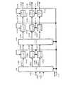
図12は、本実施の形態における重み付け方法(プリコーディング(Precoding)方法)及び位相変更方法に関連する図であり、重み付け合成部1200は、図5の重み付け合成部508A、508B、508Cを統合した重み付け合成部である。 FIG. 12 is a diagram related to the weighting method (Precoding method) and the phase changing method in the present embodiment, and
図12に示すように、ストリームs1(t)およびストリームs2(t)およびストリームs3(t)は、図5のベースバンド信号507Aおよび507Bおよび507Cに相当する、つまり、QPSK、16QAM、64QAMなどの変調方式のマッピングにしたがったベースバンド信号の同相I成分、直交Q成分となる。As shown in FIG. 12, stream s1 (t) and stream s2 (t) and stream s3 (t) correspond to baseband
そして、図12のフレーム構成のようにストリームs1(t)は、シンボル番号uの信号をs1(u)、シンボル番号u+1の信号をs1(u+1)、・・・とあらわす。同様に、ストリームs2(t)は、シンボル番号uの信号をs2(u)、シンボル番号u+1の信号をs2(u+1)、・・・とあらわす。また、ストリームs3(t)は、シンボル番号uの信号をs3(u)、シンボル番号u+1の信号をs3(u+1)、・・・とあらわす。12, the stream s1 (t) represents the signal of the symbol number u as s1 (u), the signal of the symbol number u + 1 as s1 (u + 1), and so on. Similarly, in the stream s2 (t), the signal of the symbol number u is represented as s2 (u), the signal of the symbol number u + 1 is represented as s2 (u + 1),. In the stream s3 (t), the signal of the symbol number u is represented as s3 (u), the signal of the symbol number u + 1 is represented as s3 (u + 1),.
そして、重み付け合成部1200は、図5におけるベースバンド信号507A(s1(t))および507B(s2(t))および507C(s3(t))、信号処理方法に関する情報515を入力とし、信号処理方法に関する情報515にしたがった重み付けを施し、図5の重み付け合成後の信号516A(z1’(t))、516B(z2’(t))、516C(z3’(t))を出力する。Then,
位相変更部517Aは、重み付けされた信号516A(z1’(t))の位相を変更し、位相変更後の信号509A(z1(t))を出力する。
位相変更部517Bは、重み付けされた信号516B(z2’(t))の位相を変更し、位相変更後の信号509B(z2(t))を出力する。The
位相変更部517Cは、重み付けされた信号516C(z3’(t))の位相を変更し、位相変更後の信号509C(z3(t))を出力する。The
このとき、z1(t)は、固定のプリコーディング行列Fにおける第1行のベクトルをW1=(w11,w12,w13)とし、S(t)=(s1(t),s2(t),s3(t))T、位相変更部による位相変更式をy1(t)とすると、次式(43)が成立する。
ただし、行列(またはベクトル)Aの転置行列をATとあらわすものとする。Here, the transposed matrix of the matrix (or vector) A is represented asAT .
z2(t)は、固定のプリコーディング行列Fにおける第2行のベクトルをW2=(w21,w22,w23)とし、位相変更部による位相変更式をy2(t)とすると、次式(44)が成立する。
z3(t)は、固定のプリコーディング行列Fにおける第3行のベクトルをW3=(w31,w32,w33)とし、位相変更部による位相変更式をy3(t)とすると、次式(45)が成立する。
なお、位相変更方法については、後で説明する。 The phase changing method will be described later.
図13は、本実施の形態における受信装置の構成の一例を示している。無線部1303_Xは、アンテナ1301_Xで受信された受信信号1302_Xを入力とし、周波数変換、直交復調等の処理を施し、ベースバンド信号1304_Xを出力する。 FIG. 13 shows an example of the configuration of the receiving apparatus according to the present embodiment. Radio section 1303_X receives, as input, received signal 1302_X received by antenna 1301_X, performs processing such as frequency conversion and quadrature demodulation, and outputs baseband signal 1304_X.
送信装置で送信された変調信号z1、変調信号z2、変調信号z3におけるチャネル変動推定部1305は、ベースバンド信号1304_Xを入力とし、図12におけるチャネル推定用のリファレンスシンボル1201_1を抽出し、式(42)のh11に相当する値を推定し、チャネル推定信号1306_1を出力する。Channel
また、送信装置で送信された変調信号z1、変調信号z2、変調信号z3におけるチャネル変動推定部1305は、ベースバンド信号1304_Xを入力とし、図12におけるチャネル推定用のリファレンスシンボル1201_2を抽出し、式(42)のh12に相当する値を推定し、チャネル推定信号1306_2を出力する。Further, channel
そして、送信装置で送信された変調信号z1、変調信号z2、変調信号z3におけるチャネル変動推定部1305は、ベースバンド信号1304_Xを入力とし、図12におけるチャネル推定用のリファレンスシンボル1201_3を抽出し、式(42)のh13に相当する値を推定し、チャネル推定信号1306_3を出力する。Then, channel
無線部1303_Yは、アンテナ1301_Yで受信された受信信号1302_Yを入力とし、周波数変換、直交復調等の処理を施し、ベースバンド信号1304_Yを出力する。 Radio section 1303_Y receives received signal 1302_Y received by antenna 1301_Y, performs processing such as frequency conversion and quadrature demodulation, and outputs baseband signal 1304_Y.
送信装置で送信された変調信号z1、変調信号z2、変調信号z3におけるチャネル変動推定部1307は、ベースバンド信号1304_Yを入力とし、図12におけるチャネル推定用のリファレンスシンボル1201_1を抽出し、式(42)のh21に相当する値を推定し、チャネル推定信号1308_1を出力する。Channel
また、送信装置で送信された変調信号z1、変調信号z2、変調信号z3におけるチャネル変動推定部1307は、ベースバンド信号1304_Yを入力とし、図12におけるチャネル推定用のリファレンスシンボル1201_2を抽出し、式(42)のh22に相当する値を推定し、チャネル推定信号1308_2を出力する。Further, channel
そして、送信装置で送信された変調信号z1、変調信号z2、変調信号z3におけるチャネル変動推定部1307は、ベースバンド信号1304_Yを入力とし、図12におけるチャネル推定用のリファレンスシンボル1201_3を抽出し、式(42)のh23に相当する値を推定し、チャネル推定信号1308_3を出力する。Then, channel
無線部1303_Zは、アンテナ1301_Zで受信された受信信号1302_Zを入力とし、周波数変換、直交復調等の処理を施し、ベースバンド信号1304_Zを出力する。 Radio section 1303_Z receives received signal 1302_Z received at antenna 1301_Z, performs frequency conversion, quadrature demodulation, and the like, and outputs baseband signal 1304_Z.
送信装置で送信された変調信号z1、変調信号z2、変調信号z3におけるチャネル変動推定部1309は、ベースバンド信号1304_Zを入力とし、図12におけるチャネル推定用のリファレンスシンボル1201_1を抽出し、式(42)のh31に相当する値を推定し、チャネル推定信号1310_1を出力する。Channel
また、送信装置で送信された変調信号z1、変調信号z2、変調信号z3におけるチャネル変動推定部1309は、ベースバンド信号1304_Zを入力とし、図12におけるチャネル推定用のリファレンスシンボル1201_2を抽出し、式(42)のh32に相当する値を推定し、チャネル推定信号1310_2を出力する。Further, channel
そして、送信装置で送信された変調信号z1、変調信号z2、変調信号z3におけるチャネル変動推定部1309は、ベースバンド信号1304_Zを入力とし、図12におけるチャネル推定用のリファレンスシンボル1201_3を抽出し、式(42)のh33に相当する値を推定し、チャネル推定信号1310_3を出力する。Then, channel
制御情報復号部1311は、ベースバンド信号1304_Xおよび1304_Yおよび1304_Zを入力とし、図10の送信方法を通知するためのシンボル1000_1を検出し、送信装置が通知した送信方法の情報に関する信号1312を出力する。 Control
信号処理部1313は、ベースバンド信号1304_X、1304_Y、1304_Z、チャネル推定信号1306_1、1306_2、1306_3、1308_1、1308_2、1308_3、1310_1、1310_2、1310_3及び、送信装置が通知した送信方法の情報に関する信号1312を入力とし、例えば、ML(Maximum Likelihood)検波、(誤り訂正)復号を行い、受信データ1314_1および/または1314_2および/または1314_3を出力する。 The
図13の信号処理部1313の動作について補足する。信号処理部1313は、非特許文献8、非特許文献9、非特許文献10に記載されている、例えば、MLD(Maximum Likelihood Detection)の処理を施すものとする。 The operation of the
本実施の形態における伝送方式は、時間とともに信号の位相を規則的に変更し、かつ、プリコーディング行列が使用されているMIMO伝送方式である。 The transmission method in the present embodiment is a MIMO transmission method in which the phase of a signal is regularly changed with time and a precoding matrix is used.
式(42)における(チャネル)行列をH(t)、プリコーディングウェイト行列をF、図12の位相変更部による位相変更式の行列をY(t)(ここでY(t)はtによって変化する)、受信ベクトルをR(t)=(r1(t),r2(t),r3(t))T、ストリームベクトルS(t)=(s1(t),s2(t),s3(t))Tとすると以下の関係式(46)が成立する。
このとき、受信装置は、H(t)×Y(t)×Fを得ることで、受信ベクトルR(t)に対して、例えば、MLDの検波を施すことができる。 At this time, the receiving apparatus obtains H (t) × Y (t) × F, so that the reception vector R (t) can be subjected to, for example, MLD detection.
以下では、MLDの動作について説明する。なお、以下では、変調信号(ストリーム)s1の変調方式、変調信号(ストリーム)s2の変調方式、変調信号(ストリーム)s3の変調方式がQPSKとして説明する。Hereinafter, the operation of the MLD will be described. In the following, the modulation signal (stream)s 1 modulation scheme, the modulation scheme modulated signal (stream)s 2, the modulation scheme of modulated signal (stream)s 3 is described as QPSK.
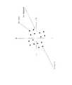
まず、チャネル推定信号1306_1、1306_2、1306_3から、ベースバンド信号1304_Xに対応する(26=64個の)候補信号点を求める。そのときの様子の例を図14に示す。図14において、●(黒丸)は、同相I―直交Q平面における候補信号点であり、QPSK3系統のため、候補信号点は64個存在する。ここで、変調信号s1で伝送する2ビットをb0、b1、変調信号s2で伝送する2ビットをb2、b3、変調信号s3で伝送する2ビットをb4、b5、とすると、図14において(b0,b1,b2,b3,b4,b5)に対応する候補信号点が存在することになる。First, (26 = 64) candidate signal points corresponding to the baseband signal 1304_X are obtained from the channel estimation signals 1306_1, 1306_2, and 1306_3. FIG. 14 shows an example of the situation at that time. In FIG. 14, ● (black circles) indicate candidate signal points on the in-phase I-quadrature Q plane, and there are 64 candidate signal points due to three QPSK systems. Here, the modulated signals 1 b0 two bits transmitted in, b1, modulated signals 2 two bits transmitted in b2, b3, modulated signals 3 in the 2 bits to be transmitted b4, b5, and when, FIG. 14 In, there is a candidate signal point corresponding to (b0, b1, b2, b3, b4, b5).
そして、受信信号点1401(ベースバンド信号1304_Xに相当する。)と候補信号点それぞれとの2乗ユークリッド距離を求める。そして、それぞれの2乗ユークリッド距離をノイズの分散σ2で除算する。したがって、(b0,b1,b2,b3,b4,b5)に対応する候補信号点と受信信号点2乗ユークリッド距離をノイズの分散で除算した値をEX(b0,b1,b2,b3,b4,b5)が求まることになる、つまり、EX(0,0,0,0,0,0)からEX(1,1,1,1,1,1)が求まることになる。なお、各ベースバンド信号、変調信号s1、s2、s3は、複素信号である。Then, the square Euclidean distance between the received signal point 1401 (corresponding to the baseband signal 1304_X) and each of the candidate signal points is obtained. Then, each squared Euclidean distance is divided by the noise variance σ2 . Therefore, (b0, b1, b2, b3, b4, b5) a value obtained by dividing candidate signal points and a received signal point square Euclidean distance variance of the noise corresponding to theE X (b0, b1, b2 , b3, b4 , b5) so that is obtained,i.e., so thatthe E X from E X (0,0,0,0,0,0) (1,1,1,1,1,1) is obtained. Note that each baseband signal and modulated signals s1 , s2 , and s3 are complex signals.
同様に、チャネル推定信号1308_1、1308_2、1308_3から、ベースバンド信号1304_Yに対応する(26=64個の)候補信号点を求める。そのときの様子の例を図14に示す。図14において、●(黒丸)は、同相I―直交Q平面における候補信号点であり、QPSK3系統のため、候補信号点は64個存在する。ここで、変調信号s1で伝送する2ビットをb0、b1、変調信号s2で伝送する2ビットをb2、b3、変調信号s3で伝送する2ビットをb4、b5、とすると、図14において(b0,b1,b2,b3,b4,b5)に対応する候補信号点が存在することになる。(ただし、図14はあくまでも説明するための例である。)Similarly, (26 = 64) candidate signal points corresponding to the baseband signal 1304_Y are obtained from the channel estimation signals 1308_1, 1308_2, and 1308_3. FIG. 14 shows an example of the situation at that time. In FIG. 14, ● (black circles) indicate candidate signal points on the in-phase I-quadrature Q plane, and there are 64 candidate signal points due to three QPSK systems. Here, the modulated signals 1 b0 two bits transmitted in, b1, modulated signals 2 two bits transmitted in b2, b3, modulated signals 3 in the 2 bits to be transmitted b4, b5, and when, FIG. 14 In, there is a candidate signal point corresponding to (b0, b1, b2, b3, b4, b5). (However, FIG. 14 is merely an example for explanation.)
そして、受信信号点1401(ベースバンド信号1304_Yに相当する。)と候補信号点それぞれとの2乗ユークリッド距離を求める。そして、それぞれの2乗ユークリッド距離をノイズの分散σ2で除算する。したがって、(b0,b1,b2,b3,b4,b5)に対応する候補信号点と受信信号点2乗ユークリッド距離をノイズの分散で除算した値をEY(b0,b1,b2,b3,b4,b5)が求まることになる、つまり、EY(0,0,0,0,0,0)からEY(1,1,1,1,1,1)が求まることになる。なお、各ベースバンド信号、変調信号s1、s2、s3は、複素信号である。Then, the square Euclidean distance between the received signal point 1401 (corresponding to the baseband signal 1304_Y) and each of the candidate signal points is obtained. Then, each squared Euclidean distance is divided by the noise variance σ2 . Therefore, the value obtained by dividing the square Euclidean distance between the candidate signal point corresponding to (b0, b1, b2, b3, b4, b5) and the received signal point by the variance of noise is EY (b0, b1, b2, b3, b4). , b5) so that is obtained,i.e., theE Y (0,0,0,0,0,0) E Y ( 1,1,1,1,1,1) that is obtained from. Note that each baseband signal and modulated signals s1 , s2 , and s3 are complex signals.
さらに、チャネル推定信号1310_1、1310_2、1310_3から、ベースバンド信号1304_Zに対応する(26=64個の)候補信号点を求める。そのときの様子の例を図14に示す。図14において、●(黒丸)は、同相I―直交Q平面における候補信号点であり、QPSK3系統のため、候補信号点は64個存在する。ここで、変調信号s1で伝送する2ビットをb0、b1、変調信号s2で伝送する2ビットをb2、b3、変調信号s3で伝送する2ビットをb4、b5、とすると、図14において(b0,b1,b2,b3,b4,b5)に対応する候補信号点が存在することになる。(ただし、図14はあくまでも説明するための例である。)Further, (26 = 64) candidate signal points corresponding to the baseband signal 1304_Z are obtained from the channel estimation signals 1310_1, 1310_2, and 1310_3. FIG. 14 shows an example of the situation at that time. In FIG. 14, ● (black circles) indicate candidate signal points on the in-phase I-quadrature Q plane, and there are 64 candidate signal points due to three QPSK systems. Here, the modulated signals 1 b0 two bits transmitted in, b1, modulated signals 2 two bits transmitted in b2, b3, modulated signals 3 in the 2 bits to be transmitted b4, b5, and when, FIG. 14 In, there is a candidate signal point corresponding to (b0, b1, b2, b3, b4, b5). (However, FIG. 14 is merely an example for explanation.)
そして、受信信号点1401(ベースバンド信号1304_Zに相当する。)と候補信号点それぞれとの2乗ユークリッド距離を求める。そして、それぞれの2乗ユークリッド距離をノイズの分散σ2で除算する。したがって、(b0,b1,b2,b3,b4,b5)に対応する候補信号点と受信信号点2乗ユークリッド距離をノイズの分散で除算した値をEZ(b0,b1,b2,b3,b4,b5)が求まることになる、つまり、EZ(0,0,0,0,0,0)からEZ(1,1,1,1,1,1)が求まることになる。なお、各ベースバンド信号、変調信号s1、s2、s3は、複素信号である。Then, the square Euclidean distance between the received signal point 1401 (corresponding to the baseband signal 1304_Z) and each of the candidate signal points is obtained. Then, each squared Euclidean distance is divided by the noise variance σ2 . Therefore, the value obtained by dividing the squared Euclidean distance between the candidate signal point corresponding to (b0, b1, b2, b3, b4, b5) and the received signal point by the noise variance isEZ (b0, b1, b2, b3, b4). , b5) so that is obtained,i.e., so thatthe E Z from E Z (0,0,0,0,0,0) (1,1,1,1,1,1) is obtained. Note that each baseband signal and modulated signals s1 , s2 , and s3 are complex signals.
そして、EX(b0,b1,b2,b3,b4,b5)+EY(b0,b1,b2,b3,b4,b5)+EZ(b0,b1,b2,b3,b4,b5)=E(b0,b1,b2,b3,b4,b5)を求める。Then, E X (b0, b1, b2, b3, b4, b5) + E Y (b0, b1, b2, b3, b4, b5) + E Z (b0, b1, b2, b3, b4, b5) = E ( b0, b1, b2, b3, b4, b5).
((b0,b1,b2,b3,b4,b5)=(0,0,0,0,0,0)のときの値がEX(0,0,0,0,0,0)+EY(0,0,0,0,0,0)+EZ(0,0,0,0,0,0)=E(0,0,0,0,0,0)となり、
(b0,b1,b2,b3,b4,b5)=(0,0,0,0,0,1)のときの値がEX(0,0,0,0,0,1)+EY(0,0,0,0,0,1)+EZ(0,0,0,0,0,1)=E(0,0,0,0,0,1)となり、
・・・
(b0,b1,b2,b3,b4,b5)=(1,1,1,1,1,1)のときの値がEX(1,1,1,1,1,1)+EY(1,1,1,1,1,1)+EZ(1,1,1,1,1,1)=E(1,1,1,1,1,1)となる。)((B0, b1, b2, b3, b4, b5) = ( value ofE X (0,0,0,0,0,0 when the 0,0,0,0,0,0)) +E Y (0,0,0,0,0,0) + EZ (0,0,0,0,0,0) = E (0,0,0,0,0,0),
(B0, b1, b2, b3 , b4, b5) = valueE X (0,0,0,0,0,1) when the (0,0,0,0,0,1)+ E Y ( 0,0,0,0,0,1) + EZ (0,0,0,0,0,1) = E (0,0,0,0,0,1),
...
(B0, b1, b2, b3 , b4, b5) = valueE X (1,1,1,1,1,1) when the (1,1,1,1,1,1)+ E Y ( (1,1,1,1,1,1) + EZ (1,1,1,1,1,1) = E (1,1,1,1,1,1). )
そして、E(b0,b1,b2,b3,b4,b5)から、例えば、各ビットの対数尤度比を求め、対数尤度比の並び替え(インタリーブ)を行い、並び替え後の対数尤度比を用いて、誤り訂正復号を行い、受信データ1314_1および/または1314_2および/または1314_3を出力する。 Then, for example, the log likelihood ratio of each bit is obtained from E (b0, b1, b2, b3, b4, b5), the log likelihood ratio is rearranged (interleaved), and the log likelihood after the rearrangement is performed. Error correction decoding is performed using the ratio to output received data 1314_1 and / or 1314_2 and / or 1314_3.
次に、本発明の課題について説明する。 Next, an object of the present invention will be described.
説明を簡単にするために、ベースバンド信号(マッピング後の信号)s3(t)がないものとして考える。このとき、ベースバンド信号(マッピング後の信号)s1(t)とベースバンド信号(マッピング後の信号)s2(t)が存在することになる。For simplicity, it is assumed that there is no baseband signal (mapped signal) s3 (t). At this time, a baseband signal (a signal after mapping) s1 (t) and a baseband signal (a signal after mapping) s2 (t) exist.
この状態で、図13の受信装置が受信した場合を考える。なお、前に説明したように、s1(t)の変調方式をQPSK方式とし、ビットb0、b1を伝送しているものとする。そして、s2(t)の変調方式をQPSK方式とし、ビットb2、b3を伝送しているものとする。In this state, consider the case where the receiving apparatus of FIG. 13 receives the signal. As described above, it is assumed that the modulation scheme of s1 (t) is the QPSK scheme and bits b0 and b1 are transmitted. Then, it is assumed that the modulation scheme of s2 (t) is the QPSK scheme and bits b2 and b3 are transmitted.
図15に、図13の信号処理部1313における、同相I−直交Q平面の受信状態の一例(候補信号点の状態)を示している。図15において、●(黒丸)は、IQ平面における候補信号点であり、s1(t)でb0、b1、s2(t)でb2、b3を伝送しているため、理想的には、図15のように、16個の候補信号点((b0,b1,b2,b3)が(0,0,0,0)から(1,1,1,1)に対応する候補信号点が存在する。)が存在する。FIG. 15 shows an example of the reception state (state of candidate signal points) in the in-phase I-quadrature Q plane in the
図16に、図13の信号処理部1313における、同相I−直交平面の受信状態の一例(候補信号点の状態)を示している。図16において、●(黒丸)は、IQ平面における候補信号点である。 FIG. 16 shows an example of the reception state of the in-phase I-quadrature plane (state of candidate signal points) in
候補信号点1602は、(b0,b1,b2,b3)が(0,0,0,0)に対応する候補信号点である。 The candidate signal point 1602 is a candidate signal point in which (b0, b1, b2, b3) corresponds to (0, 0, 0, 0).
候補信号点1603は、(b0,b1,b2,b3)が(0,0,0,1)(0,1,0,0)に対応する候補信号点である。 The candidate signal point 1603 is a candidate signal point in which (b0, b1, b2, b3) corresponds to (0, 0, 0, 1) (0, 1, 0, 0).
候補信号点1604は、(b0,b1,b2,b3)が(0,1,0,1)に対応する候補信号点である。 The candidate signal point 1604 is a candidate signal point in which (b0, b1, b2, b3) corresponds to (0, 1, 0, 1).
候補信号点1605は、(b0,b1,b2,b3)が(1,1,0,1)(0,1,1,1)に対応する候補信号点である。 The candidate signal point 1605 is a candidate signal point where (b0, b1, b2, b3) corresponds to (1, 1, 0, 1) (0, 1, 1, 1).
候補信号点1606は、(b0,b1,b2,b3)が(1,1,1,1)に対応する候補信号点である。 The candidate signal point 1606 is a candidate signal point in which (b0, b1, b2, b3) corresponds to (1, 1, 1, 1).
候補信号点1607は、(b0,b1,b2,b3)が(1,1,1,0)(1,0,1,1)に対応する候補信号点である。 The candidate signal point 1607 is a candidate signal point in which (b0, b1, b2, b3) corresponds to (1, 1, 1, 0) (1, 0, 1, 1).
候補信号点1608は、(b0,b1,b2,b3)が(1,0,1,0)に対応する候補信号点である。 The candidate signal point 1608 is a candidate signal point in which (b0, b1, b2, b3) corresponds to (1, 0, 1, 0).
候補信号点1609は、(b0,b1,b2,b3)が(1,0,0,0)(0,0,1,0)に対応する候補信号点である。 The candidate signal point 1609 is a candidate signal point in which (b0, b1, b2, b3) corresponds to (1, 0, 0, 0) (0, 0, 1, 0).
候補信号点1610は、(b0,b1,b2,b3)が(0,0,1,1)(0,1,1,0)(1,1,0,0)(1,0,0,1)に対応する候補信号点である。 The candidate signal point 1610 is such that (b0, b1, b2, b3) is (0, 0, 1, 1) (0, 1, 1, 0) (1, 1, 0, 0) (1, 0, 0, This is a candidate signal point corresponding to 1).
このように、図16では、図15のような理想的な状態と比較すると、候補信号点の数が少なっている。受信装置は図16のような状態で受信した場合、受信データ品質の低下を招くことになる。特に、直接波の支配的な環境では、直接波の影響が強いため、伝播環境が定常的であり、これにより、低いデータの受信品質の状態が長時間続く現象に陥る可能性がある。なお、図16では、候補信号点が重なっているときを例に説明しているが、例えば、16個の候補信号点の最小ユークリッド距離が小さくなっているときについても同様に、データの受信品質の低下を招くことになる(特に、直接波の支配的な環境で、データの受信品質の低下が発生する可能性が高い。) Thus, in FIG. 16, the number of candidate signal points is smaller than in the ideal state as shown in FIG. When the receiving apparatus receives data in the state as shown in FIG. 16, the received data quality is degraded. In particular, in an environment where a direct wave is dominant, the influence of the direct wave is strong, so that the propagation environment is stationary, which may lead to a phenomenon in which the state of low data reception quality continues for a long time. Although FIG. 16 illustrates an example in which candidate signal points overlap, for example, when the minimum Euclidean distance of 16 candidate signal points is small, the reception quality of data is similarly reduced. (Particularly, in a dominant environment of direct waves, there is a high possibility that the data reception quality will decrease).
このような候補信号点が重なる現象は、3つのベースバンド信号、つまり、s1(t)、s2(t)、s3(t)が存在するときについても同様に発生する。そして、「特に、直接波の支配的な環境では、直接波の影響が強いため、伝播環境が定常的であり、これにより、低いデータの受信品質の状態が長時間続く現象に陥る可能性がある」という課題に対し、データの受信品質を改善する方法について、以下で説明する。Such a phenomenon that candidate signal points overlap also occurs when three baseband signals exist, that is, s1 (t), s2 (t), and s3 (t). "Especially, in the environment where the direct wave is dominant, the propagation environment is steady due to the strong influence of the direct wave, which may lead to the phenomenon that the state of low data reception quality lasts for a long time. A method for improving the data reception quality with respect to the problem of "there is" will be described below.
図17は、図5、図6の送信装置の位相変更部517A、位相変更部517B、位相変更部517Cにおける位相変更値の具体的な例を示している。なお、上述で説明したように、位相変更部517Aの位相変更値をy1(t)、位相変更部517Bの位相変更値をy2(t)、位相変更部517Cの位相変更値をy3(t)とする。図17において、tは時間であり(ただし、ここでは、y1(t)、y2(t)、y3(t)のように時間の関数としているが、前述のように、周波数、周波数および時間の関数であってもよい。)、「0」と記載しているが、0ラジアンであることを意味し、「a」と記載しているが、aラジアンであることを意味し、「b」と記載しているが、bラジアンであることを意味している。なお、aは0≦a<2πとし、bは0≦b<2πとし、a≠0、b≠0、a≠bであるものとする。FIG. 17 illustrates a specific example of the phase change values in the
図17に示したように、
・時刻t=0において、y1(0)=0(ラジアン)、y2(0)=0(ラジアン)、y3(0)=0(ラジアン)
・時刻t=1において、y1(1)=0(ラジアン)、y2(1)=a(ラジアン)、y3(1)=0(ラジアン)
・時刻t=2において、y1(2)=0(ラジアン)、y2(2)=b(ラジアン)、y3(2)=0(ラジアン)
・時刻t=3において、y1(3)=0(ラジアン)、y2(3)=0(ラジアン)、y3(3)=0(ラジアン)
・時刻t=4において、y1(4)=0(ラジアン)、y2(4)=a(ラジアン)、y3(4)=0(ラジアン)
・時刻t=5において、y1(5)=0(ラジアン)、y2(5)=b(ラジアン)、y3(5)=0(ラジアン)
・・・
であるものとする。As shown in FIG.
At time t = 0, y1 (0) = 0 (radian), y2 (0) = 0 (radian), y3 (0) = 0 (radian)
At time t = 1, y1 (1) = 0 (radian), y2 (1) = a (radian), y3 (1) = 0 (radian)
At time t = 2, y1 (2) = 0 (radian), y2 (2) = b (radian), y3 (2) = 0 (radian)
At time t = 3, y1 (3) = 0 (radian), y2 (3) = 0 (radian), y3 (3) = 0 (radian)
At time t = 4, y1 (4) = 0 (radian), y2 (4) = a (radian), y3 (4) = 0 (radian)
At time t = 5, y1 (5) = 0 (radian), y2 (5) = b (radian), y3 (5) = 0 (radian)
...
It is assumed that
図17では、位相変更に関する周期は3であるものとする。したがって、
・時刻t=3kにおいて、y1(3k)=0(ラジアン)、y2(3k)=0(ラジアン)、y3(3k)=0(ラジアン)
・時刻t=3k+1において、y1(3k+1)=0(ラジアン)、y2(3k+1)=a(ラジアン)、y3(3k+1)=0(ラジアン)
・時刻t=3k+2において、y1(3k+2)=0(ラジアン)、y2(3k+2)=b(ラジアン)、y3(3k+2)=0(ラジアン)
となる。なお、例えば、kは0以上の整数とする。In FIG. 17, it is assumed that the cycle related to the phase change is 3. Therefore,
At time t = 3k, y1 (3k) = 0 (radian), y2 (3k) = 0 (radian), y3 (3k) = 0 (radian)
At time t = 3k + 1, y1 (3k + 1) = 0 (radian), y2 (3k + 1) = a (radian), y3 (3k + 1) = 0 (radian)
At time t = 3k + 2, y1 (3k + 2) = 0 (radian), y2 (3k + 2) = b (radian), y3 (3k + 2) = 0 (radian)
Becomes For example, k is an integer of 0 or more.
図17のような位相変更を行ったときの課題について説明する。 A problem when the phase is changed as shown in FIG. 17 will be described.
図13の受信装置が、図5、図6の送信装置が送信した変調信号を受信する際、例えば、アンテナ512Bから送信される変調信号の受信電界強度が、図13の受信装置で低い場合を考える。なお、以下では、上述と同様、、変調信号(ストリーム)s1の変調方式、変調信号(ストリーム)s2の変調方式、変調信号(ストリーム)s3の変調方式がQPSKとする。したがって、MLDを施す際、候補信号点の重なりが発生しなければ、同相I−直交Q平面において、64個の候補信号点が出現することになる。When the receiving apparatus of FIG. 13 receives the modulated signal transmitted by the transmitting apparatus of FIGS. 5 and 6, for example, the reception field strength of the modulated signal transmitted from the
ここで、上述に記載したように、「アンテナ512Bから送信される変調信号の受信電界強度が、図13の受信装置で低い」場合を考える。そして、直接波が支配的な環境下で、かつ、MLDを施した際、64個の候補信号点において、最小ユークリッド距離が短く、データの受信品質が劣悪な環境に陥っている場合を考える。このような環境下で、図17のような位相変更を行っている場合を考える。 Here, as described above, the case where “the received electric field strength of the modulated signal transmitted from the
このとき、図13の受信装置にとって、受信状態に影響を与える信号は、図5、図6の送信装置のアンテナ512Aから送信された変調信号およびアンテナ512Cから送信された変調信号となる。 At this time, for the receiving device in FIG. 13, the signals that affect the reception state are the modulated signal transmitted from
図17に示した位相変更を行った場合、図5、図6の送信装置のアンテナ512Aから送信された変調信号に対して位相変更を行っておらず、また、図5、図6の送信装置のアンテナ512Cから送信された変調信号に対しても位相変更を行っていない。したがって、図13における、同相I−直交Q平面における候補信号点の状態は、時間tに対して、大きな変化を起こさない可能性が高い。(候補信号点の最小ユークリッド距離が大きく変化しない可能性が高い。)よって、図13の受信装置において、データの受信品質が低下している場合、その状態が保持される可能性が高い。 When the phase change shown in FIG. 17 is performed, the phase change is not performed on the modulated signal transmitted from the
この課題を克服するための位相変更の方法の一例が図18である。 FIG. 18 shows an example of a phase changing method for overcoming this problem.
図18は、図5、図6の送信装置の位相変更部517A、位相変更部517B、位相変更部517Cにおける位相変更値の具体的な例を示している。なお、上述で説明したように、位相変更部517Aの位相変更値をy1(t)、位相変更部517Bの位相変更値をy2(t)、位相変更部517Cの位相変更値をy3(t)とする。図17において、tは時間であり(ただし、ここでは、y1(t)、y2(t)、y3(t)のように時間の関数としているが、前述のように、周波数、周波数および時間の関数であってもよい。)、「0」と記載しているが、0ラジアンであることを意味し、「a」と記載しているが、aラジアンであることを意味し、「b」と記載しているが、bラジアンであることを意味している。なお、aは0≦a<2πとし、bは0≦b<2πとし、a≠0、b≠0、a≠bであるものとする。FIG. 18 illustrates a specific example of the phase change values in the
図18に示したように、
・時刻t=0において、y1(0)=0(ラジアン)、y2(0)=0(ラジアン)、y3(0)=0(ラジアン)
・時刻t=1において、y1(1)=0(ラジアン)、y2(1)=a(ラジアン)、y3(1)=0(ラジアン)
・時刻t=2において、y1(2)=0(ラジアン)、y2(2)=b(ラジアン)、y3(2)=0(ラジアン)
・時刻t=3において、y1(3)=0(ラジアン)、y2(3)=0(ラジアン)、y3(3)=a(ラジアン)
・時刻t=4において、y1(4)=0(ラジアン)、y2(4)=0(ラジアン)、y3(4)=b(ラジアン)
・時刻t=5において、y1(5)=0(ラジアン)、y2(5)=a(ラジアン)、y3(5)=a(ラジアン)
・時刻t=6において、y1(6)=0(ラジアン)、y2(6)=a(ラジアン)、y3(6)=b(ラジアン)
・時刻t=7において、y1(7)=0(ラジアン)、y2(7)=b(ラジアン)、y3(7)=a(ラジアン)
・時刻t=8において、y1(8)=0(ラジアン)、y2(8)=b(ラジアン)、y3(8)=b(ラジアン)
・・・
であるものとする。As shown in FIG.
At time t = 0, y1 (0) = 0 (radian), y2 (0) = 0 (radian), y3 (0) = 0 (radian)
At time t = 1, y1 (1) = 0 (radian), y2 (1) = a (radian), y3 (1) = 0 (radian)
At time t = 2, y1 (2) = 0 (radian), y2 (2) = b (radian), y3 (2) = 0 (radian)
At time t = 3, y1 (3) = 0 (radian), y2 (3) = 0 (radian), y3 (3) = a (radian)
At time t = 4, y1 (4) = 0 (radian), y2 (4) = 0 (radian), y3 (4) = b (radian)
At time t = 5, y1 (5) = 0 (radian), y2 (5) = a (radian), y3 (5) = a (radian)
At time t = 6, y1 (6) = 0 (radian), y2 (6) = a (radian), y3 (6) = b (radian)
At time t = 7, y1 (7) = 0 (radian), y2 (7) = b (radian), y3 (7) = a (radian)
At time t = 8, y1 (8) = 0 (radian), y2 (8) = b (radian), y3 (8) = b (radian)
...
It is assumed that
図18では、位相変更に関する周期は9であるものとする。したがって、
・時刻t=9kにおいて、y1(9k)=0(ラジアン)、y2(9k)=0(ラジアン)、y3(9k)=0(ラジアン)
・時刻t=9k+1において、y1(9k+1)=0(ラジアン)、y2(9k+1)=a(ラジアン)、y3(9k+1)=0(ラジアン)
・時刻t=9k+2において、y1(9k+2)=0(ラジアン)、y2(9k+2)=b(ラジアン)、y3(9k+2)=0(ラジアン)
・時刻t=9k+3において、y1(9k+3)=0(ラジアン)、y2(9k+3)=0(ラジアン)、y3(9k+3)=a(ラジアン)
・時刻t=9k+4において、y1(9k+4)=0(ラジアン)、y2(9k+4)=0(ラジアン)、y3(9k+4)=b(ラジアン)
・時刻t=9k+5において、y1(9k+5)=0(ラジアン)、y2(9k+5)=a(ラジアン)、y3(9k+5)=a(ラジアン)
・時刻t=9k+6において、y1(9k+6)=0(ラジアン)、y2(9k+6)=a(ラジアン)、y3(9k+6)=b(ラジアン)
・時刻t=9k+7において、y1(9k+7)=0(ラジアン)、y2(9k+7)=b(ラジアン)、y3(9k+7)=a(ラジアン)
・時刻t=9k+8において、y1(9k+8)=0(ラジアン)、y2(9k+8)=b(ラジアン)、y3(9k+8)=b(ラジアン)
となる。なお、例えば、kは0以上の整数とする。In FIG. 18, it is assumed that the cycle related to the phase change is 9. Therefore,
At time t = 9k, y1 (9k) = 0 (radian), y2 (9k) = 0 (radian), y3 (9k) = 0 (radian)
At time t = 9k + 1, y1 (9k + 1) = 0 (radian), y2 (9k + 1) = a (radian), y3 (9k + 1) = 0 (radian)
At time t = 9k + 2, y1 (9k + 2) = 0 (radian), y2 (9k + 2) = b (radian), y3 (9k + 2) = 0 (radian)
At time t = 9k + 3, y1 (9k + 3) = 0 (radian), y2 (9k + 3) = 0 (radian), y3 (9k + 3) = a (radian)
At time t = 9k + 4, y1 (9k + 4) = 0 (radian), y2 (9k + 4) = 0 (radian), y3 (9k + 4) = b (radian)
At time t = 9k + 5, y1 (9k + 5) = 0 (radian), y2 (9k + 5) = a (radian), y3 (9k + 5) = a (radian)
At time t = 9k + 6, y1 (9k + 6) = 0 (radian), y2 (9k + 6) = a (radian), y3 (9k + 6) = b (radian)
At time t = 9k + 7, y1 (9k + 7) = 0 (radian), y2 (9k + 7) = b (radian), y3 (9k + 7) = a (radian)
At time t = 9k + 8, y1 (9k + 8) = 0 (radian), y2 (9k + 8) = b (radian), y3 (9k + 8) = b (radian)
Becomes For example, k is an integer of 0 or more.
図18のような位相変更を行ったときの利点について説明する。 Advantages when the phase change as shown in FIG. 18 is performed will be described.
図17について説明したときと同様に、図13の受信装置が、図5、図6の送信装置が送信した変調信号を受信する際、例えば、アンテナ512Bから送信される変調信号の受信電界強度が、図13の受信装置で低い場合を考える。なお、以下では、上述と同様、変調信号(ストリーム)s1の変調方式、変調信号(ストリーム)s2の変調方式、変調信号(ストリーム)s3の変調方式がQPSKとする。したがって、MLDを施す際、候補信号点の重なりが発生しなければ、同相I−直交Q平面において、64個の候補信号点が出現することになる。Similarly to the case described with reference to FIG. 17, when the receiving apparatus of FIG. 13 receives the modulated signal transmitted by the transmitting apparatus of FIGS. 5 and 6, for example, the reception electric field strength of the modulated signal transmitted from the
ここで、上述に記載したように、「アンテナ512Bから送信される変調信号の受信電界強度が、図13の受信装置で低い」場合を考える。そして、直接波が支配的な環境下で、かつ、MLDを施した際、64個の候補信号点において、最小ユークリッド距離が短く、データの受信品質が劣悪な環境に陥っている場合を考える。このような環境下で、図18のような位相変更を行っている場合を考える。 Here, as described above, the case where “the received electric field strength of the modulated signal transmitted from the
このとき、図13の受信装置にとって、受信状態に影響を与える信号は、図5、図6の送信装置のアンテナ512Aから送信された変調信号およびアンテナ512Cから送信された変調信号となる。 At this time, for the receiving device in FIG. 13, the signals that affect the reception state are the modulated signal transmitted from
図18に示した位相変更を行った場合、t=0、t=1、t=2において、図5、図6の送信装置のアンテナ512Aから送信された変調信号に対して位相変更を行っておらず、また、図5、図6の送信装置のアンテナ512Cから送信された変調信号に対しても位相変更を行っていない。したがって、図13における、同相I−直交Q平面における候補信号点の状態は、時間t=0、t=1、t=2では、大きな変化を起こさない可能性が高い。(候補信号点の最小ユークリッド距離が大きく変化しない可能性が高い。)
しかし、t=3からt=8において、図5、図6の送信装置のアンテナ512Cから送信された変調信号において、0(ゼロ)ラジアン以外の位相を与えているため、この区間で、同相I−直交Q平面におる候補信号点の状態が改善(候補信号点の最小ユークリッド距離が大きくなる)している可能性がある。When the phase change shown in FIG. 18 is performed, at t = 0, t = 1, and t = 2, the phase change is performed on the modulated signal transmitted from the
However, from t = 3 to t = 8, the modulated signal transmitted from the
よって、図17のときと比較し、候補信号点の状態が良好(候補信号点の最小ユークリッド距離が大きい)な時間が増加し、誤り訂正符号の適用により、受信品質が改善される可能性が高くなるという効果を得ることができる。 Therefore, as compared with the case of FIG. 17, the time during which the state of the candidate signal point is good (the minimum Euclidean distance of the candidate signal point is large) increases, and there is a possibility that the reception quality is improved by applying the error correction code. The effect of increasing the height can be obtained.
次に、「アンテナ512Cから送信される変調信号の受信電界強度が、図13の受信装置で低い」場合を考える。そして、直接波が支配的な環境下で、かつ、MLDを施した際、64個の候補信号点において、最小ユークリッド距離が短く、データの受信品質が劣悪な環境に陥っている場合を考える。このような環境下で、図18のような位相変更を行っている場合を考える。 Next, consider the case where “the received electric field strength of the modulated signal transmitted from
このとき、図13の受信装置にとって、受信状態に影響を与える信号は、図5、図6の送信装置のアンテナ512Aから送信された変調信号およびアンテナ512Bから送信された変調信号となる。 At this time, for the receiving apparatus in FIG. 13, the signals that affect the receiving state are the modulated signal transmitted from
図18に示した位相変更を行った場合、t=0、t=3、t=4において、図5、図6の送信装置のアンテナ512Aから送信された変調信号に対して位相変更を行っておらず、また、図5、図6の送信装置のアンテナ512Bから送信された変調信号に対しても位相変更を行っていない。したがって、図13における、同相I−直交Q平面における候補信号点の状態は、時間t=0、t=3、t=4では、大きな変化を起こさない可能性が高い。(候補信号点の最小ユークリッド距離が大きく変化しない可能性が高い。) When the phase change shown in FIG. 18 is performed, at t = 0, t = 3, and t = 4, the phase change is performed on the modulated signal transmitted from the
しかし、t=1,t=2,t=5,t=6,t=7,t=8おいて、図5、図6の送信装置のアンテナ512Bから送信された変調信号において、0(ゼロ)ラジアン以外の位相を与えているため、これらの時間で、同相I−直交Q平面におる候補信号点の状態が改善(候補信号点の最小ユークリッド距離が大きくなる)している可能性がある。 However, at t = 1, t = 2, t = 5, t = 6, t = 7, and t = 8, in the modulated signal transmitted from the
よって、図17のときと比較し、候補信号点の状態が良好(候補信号点の最小ユークリッド距離が大きい)な時間が増加し、誤り訂正符号の適用により、受信品質が改善される可能性が高くなるという効果を得ることができる。 Therefore, as compared with the case of FIG. 17, the time during which the state of the candidate signal point is good (the minimum Euclidean distance of the candidate signal point is large) increases, and there is a possibility that the reception quality is improved by applying the error correction code. The effect of increasing the height can be obtained.
次に、「アンテナ512Aから送信される変調信号の受信電界強度が、図13の受信装置で低い」場合を考える。そして、直接波が支配的な環境下で、かつ、MLDを施した際、64個の候補信号点において、最小ユークリッド距離が短く、データの受信品質が劣悪な環境に陥っている場合を考える。このような環境下で、図18のような位相変更を行っている場合を考える。 Next, a case where “the received electric field strength of the modulated signal transmitted from the
このとき、図13の受信装置にとって、受信状態に影響を与える信号は、図5、図6の送信装置のアンテナ512Bから送信された変調信号およびアンテナ512Cから送信された変調信号となる。 At this time, for the receiving apparatus of FIG. 13, the signals that affect the reception state are the modulated signal transmitted from
図18に示した位相変更を行った場合、t=0、t=5、t=8において、図5、図6の送信装置のアンテナ512Bから送信された変調信号と図5、図6の送信装置のアンテナ512Cから送信された変調信号の相対的な位相関係は変わらない。(図5、図6の送信装置のアンテナ512Bから送信された変調信号の位相と図5、図6の送信装置のアンテナ512Cから送信された変調信号の位相差は、t=0、t=5、t=8と同一の値となる。)したがって、図13における、同相I−直交Q平面における候補信号点の状態は、時間t=0、t=5、t=8では、大きな変化を起こさない可能性が高い。(候補信号点の最小ユークリッド距離が大きく変化しない可能性が高い。)(相対的な位相関係が変わらない場合、候補信号点の状態は変化しない。) When the phase change shown in FIG. 18 is performed, at t = 0, t = 5, and t = 8, the modulated signal transmitted from the
しかし、t=1,t=2,t=3,t=4,t=6,t=7おいて、図5、図6の送信装置のアンテナ512Bから送信された変調信号と図5、図6の送信装置のアンテナ512Cから送信された変調信号の相対的な位相関係が変化しており、図5、図6の送信装置のアンテナ512Bから送信された変調信号において、複数の位相を与えており、また、図5、図6の送信装置のアンテナ512Cから送信された変調信号において、複数の位相を与えているため、これらの時間で、同相I−直交Q平面におる候補信号点の状態が改善(候補信号点の最小ユークリッド距離が大きくなる)している可能性がある。 However, at t = 1, t = 2, t = 3, t = 4, t = 6, t = 7, the modulated signal transmitted from the
よって、図17のときと比較し、候補信号点の状態が良好(候補信号点の最小ユークリッド距離が大きい)な時間が増加し、誤り訂正符号の適用により、受信品質が改善される可能性が高くなるという効果を得ることができる。 Therefore, as compared with the case of FIG. 17, the time during which the state of the candidate signal point is good (the minimum Euclidean distance of the candidate signal point is large) increases, and there is a possibility that the reception quality is improved by applying the error correction code. The effect of increasing the height can be obtained.
以上より、図5、図6の送信アンテナ512A、512B、512Cのいずれの状態が劣悪になっても、データの受信品質が劣悪な状態に陥る可能性が低くなるという効果を得ることができる。 As described above, even if any of the
上述では、位相変更の例、および、図18のように位相変更を行ったときの効果を説明した。以下では、同様の効果を得るための位相変更方法の別の例について説明する。 In the above, the example of the phase change and the effect when the phase is changed as shown in FIG. 18 have been described. Hereinafter, another example of the phase changing method for obtaining the same effect will be described.
図5、図6の位相変更部517Aの位相変更値y1(t)がとりうる値をa1のみであるものとする。5, the value
そして、図5、図6の位相変更部517Bの位相変更値y2(t)がとりうる値はm種類であり(mは2以上の整数とする。)、その値をbi(ラジアン)とあらわすものとする(なお、iは1以上m以下の整数とする。また、0≦bi<2πとする)。ただし、iおよびjは1以上m以下の整数であり、かつ、i≠jであり、これを満たす、すべてのi、jにおいて、bi≠bjを満たすものとする。There are m possible values of the phase change value y2 (t) of the
また、図5、図6の位相変更部517Cの位相変更値y3(t)がとりうる値はn種類であり(nは2以上の整数とする。)、その値をci(ラジアン)とあらわすものとする(なお、iは1以上n以下の整数とする。また、0≦ci<2πとする)。ただし、iおよびjは1以上n以下の整数であり、かつ、i≠jであり、これを満たす、すべてのi、jにおいて、ci≠cjを満たすものとする。Further, FIG. 5, the value
このとき、シンボル番号u(ただし、uは0以上の整数とする。)における(y1(u)、y2(u)、y3(u))のセットがとる値を(a1、bi、cj)とすると、以下の条件を満たすことになる。At this time, the values of the set of (y1 (u), y2 (u), y3 (u)) in the symbol number u (where u is an integer equal to or greater than 0) are (a1 , b)i , cj ), the following condition is satisfied.
(条件1)
i=β(βは1以上m以下の整数とする。)とする。このとき、(y1(u)、y2(u)、y3(u))=(a1、bβ、cj)とあらわす((y1(u)、y2(u)、y3(u))=(a1、bβ、cj)とは、y1(u)=a1、y2(u)=bβ、y3(u)=cjであることを意味する。)。そして、uが0以上の整数において、i=βを満たしたとき、cjにおいて、jは1以上n以下の整数すべての値をとる。(Condition 1)
i = β (β is an integer of 1 or more and m or less). At this time, (y1 (u), y2 (u), y3 (u)) = (a1 , bβ , cj ) ((y1 (u), y2 (u), y3 (u)) = (a1 , bβ , cj ) means that y1 (u) = a1 , y2 (u) = bβ , and y3 (u) = cj. I do.) Then, when u satisfies i = β in an integer of 0 or more, in cj , j takes all values of an integer of 1 or more and n or less.
(条件2)
そして、1以上m以下の整数すべてのβにおいて、「uが0以上の整数において、i=βを満たしたとき、cjにおいて、jは0以上n以下の整数すべての値をとる」の条件を満たす。(Condition 2)
Then, for all βs of 1 or more and m or less, a condition that “when u satisfies i = β in an integer of 0 or more, in cj , j takes values of all integers of 0 or more and n or less” Meet.
(条件1)および(条件2)を満たすことにより、図18のように位相変更を行ったときの効果を得ることができる。なお、(条件1)および(条件2)を満たすための位相変更の周期の最低の値はm×nとなるが、位相変更の周期はm×n以上であってもよい。(この場合、同一の位相変更のセットが2度以上用いられ、その条件下で、位相変更の周期が設定されることになる。) By satisfying (Condition 1) and (Condition 2), the effect when the phase is changed as shown in FIG. 18 can be obtained. The minimum value of the phase change cycle for satisfying (condition 1) and (condition 2) is m × n, but the phase change cycle may be m × n or more. (In this case, the same set of phase changes is used twice or more, and under that condition, the phase change cycle is set.)
図18、および、上述の例では、図5、図6の位相変更部517Aの位相変更値y1(t)を一定値とした場合の位相変更方法について説明した。以下では、図5、図6の位相変更部517Aの位相変更値y1(t)を時間(周波数)(周波数および時間)により変更する場合の位相変更方法の例を説明する。In FIG. 18 and the above-described example, the phase changing method when the phase changing value y1 (t) of the
図5、図6の位相変更部517Aの位相変更値y1(t)がとりうる値はp種類であり(pは2以上の整数とする。)、その値をai(ラジアン)とあらわすものとする(なお、iは1以上p以下の整数とする。また、0≦ai<2πとする)。ただし、iおよびjは1以上p以下の整数であり、かつ、i≠jであり、これを満たす、すべてのi、jにおいて、ai≠ajを満たすものとする。The possible values of the phase change value y1 (t) of the
そして、図5、図6の位相変更部517Bの位相変更値y2(t)がとりうる値はm種類であり(mは2以上の整数とする。)、その値をbi(ラジアン)とあらわすものとする(なお、iは1以上m以下の整数とする。また、0≦bi<2πとする)。ただし、iおよびjは1以上m以下の整数であり、かつ、i≠jであり、これを満たす、すべてのi、jにおいて、bi≠bjを満たすものとする。There are m possible values of the phase change value y2 (t) of the
また、図5、図6の位相変更部517Cの位相変更値y3(t)がとりうる値はn種類であり(nは2以上の整数とする。)、その値をci(ラジアン)とあらわすものとする(なお、iは1以上n以下の整数とする。また、0≦ci<2πとする)。ただし、iおよびjは1以上n以下の整数であり、かつ、i≠jであり、これを満たす、すべてのi、jにおいて、ci≠cjを満たすものとする。Further, FIG. 5, the value
このとき、シンボル番号u(ただし、uは0以上の整数とする。)における(y1(u)、y2(u)、y3(u))のセットがとる値を(ai、bj、ck)とすると、以下の条件を満たすことになる。At this time, the values taken by the set of (y1 (u), y2 (u), y3 (u)) in the symbol number u (where u is an integer equal to or greater than 0) are (ai , bj ,ck ), the following condition is satisfied.
(条件3)
i=β(βは1以上p以下の整数とする。)とする。このとき、(y1(u)、y2(u)、y3(u))=(aβ、bj、ck)とあらわす((y1(u)、y2(u)、y3(u))=(aβ、bj、ck)とは、y1(u)=aβ、y2(u)=bj、y3(u)=ckであることを意味する。)。そして、uが0以上の整数において、i=βを満たしたとき、(aβ、bj、ck)において、jは0以上m以下の整数、kは0以上n以下の整数とし、(j,k)のとりえるすべての(j,k)セットが存在する。(Condition 3)
i = β (β is an integer of 1 or more and p or less). At this time, (y1 (u), y2 (u), y3 (u)) = (aβ , bj ,ck ) is expressed as ((y1 (u), y2 (u), y3 (u)) = (a β, b j, means that ack), which isy 1 (u) = a β , y 2 (u) = b j, y 3 (u) = c k I do.) When u is an integer of 0 or more and i = β is satisfied, in (aβ , bj ,ck ), j is an integer of 0 or more and m or less, k is an integer of 0 or more and n or less, and ( There are all possible (j, k) sets of (j, k).
(条件4)
そして、1以上p以下の整数すべてのβにおいて、「uが0以上の整数において、i=βを満たしたとき、(aβ、bj、ck)において、jは0以上m以下の整数、kは0以上n以下の整数とし、(j,k)のとりえるすべての(j,k)セットが存在する。」の条件を満たす。(Condition 4)
Then, for all the integers of 1 or more and p or less, when “u is an integer of 0 or more and i = β, j is an integer of 0 or more and m or less in (aβ , bj ,ck ). , K are integers from 0 to n, and there are all possible (j, k) sets of (j, k). "
(条件3)および(条件4)を満たすことにより、図18のように位相変更を行ったときの効果を得ることができる。なお、(条件3)および(条件4)を満たすための位相変更の周期の最低の値はp×m×nとなるが、位相変更の周期はp×m×n以上であってもよい。(この場合、同一の位相変更のセットが2度以上用いられ、その条件下で、位相変更の周期が設定されることになる。) By satisfying (Condition 3) and (Condition 4), the effect when the phase is changed as shown in FIG. 18 can be obtained. The minimum value of the phase change cycle for satisfying (condition 3) and (condition 4) is p × m × n, but the phase change cycle may be p × m × n or more. (In this case, the same set of phase changes is used twice or more, and under that condition, the phase change cycle is set.)
なお、受信装置において、H(t)×Y(t)×Fを得、MLDを行う場合を例に説明したが、非特許文献9に示されているようにQR分解を用いて、検波を実行してもよい。 In the receiving apparatus, H (t) × Y (t) × F is obtained and MLD is performed as an example. However, as described in
また、非特許文献11に示されているように、H(t)×Y(t)×Fに基づき、MMSE(Minimum Mean Square Error)、ZF(Zero Forcing)の線形演算を行い、検波を行ってもよい。 Further, as shown in
本実施の形態では、シングルキャリア方式を例に説明したが、これに限ったものではなく、マルチキャリア伝送を行った場合でも同様に実施することができる。したがって、例えば、スペクトル拡散通信方式、OFDM(Orthogonal Frequency−Division Multiplexing)方式、SC−FDMA(Single Carrier Frequency Division Multiple Access)、SC−OFDM(Single Carrier Orthogonal Frequency−Division Multiplexing)方式、非特許文献12等で示されているウェーブレットOFDM方式等を用いた場合についても同様に実施することができる。また、本実施の形態では、データシンボル以外のシンボル、例えば、パイロットシンボル(プリアンブル、ユニークワード等)、制御情報の伝送用のシンボルなどが、フレームにどのように配置されていてもよい。 In the present embodiment, the single-carrier scheme has been described as an example, but the present invention is not limited to this, and the present invention can be similarly implemented when multi-carrier transmission is performed. Therefore, for example, spread spectrum communication system, OFDM (Orthogonal Frequency-Division Multiplexing) system, SC-FDMA (Single Carrier Frequency Division Multiple Multiple Access System, etc.), SC-OFDM The same can be applied to the case where the wavelet OFDM method or the like shown in FIG. Further, in the present embodiment, symbols other than data symbols, for example, pilot symbols (preamble, unique word, etc.), symbols for transmitting control information, and the like may be arranged in any manner in a frame.
以下では、マルチキャリア方式の一例として、OFDM方式を用いたときの例を説明する。 Hereinafter, an example in which the OFDM method is used will be described as an example of the multicarrier method.
図19、図20は、OFDM方式を用いたときの送信装置の構成を示している。図19において、図5、図6と同様に動作するものについては、同一符号を付した。 FIG. 19 and FIG. 20 show the configuration of the transmission device when the OFDM method is used. In FIG. 19, components that operate in the same manner as in FIGS. 5 and 6 are denoted by the same reference numerals.
OFDM方式関連処理部1901Aは、位相変更後の信号509Aを入力とし、OFDM方式関連の処理を施し、送信信号1902Aを出力する。同様に、OFDM方式関連処理部1901Bは、位相変更後の信号509Bを入力とし、送信信号1902Bを出力し、OFDM方式関連処理部1901Cは、位相変更後の信号509Cを入力とし、送信信号1902Cを出力する。 The OFDM system-related
図21は、図19、図20のOFDM方式関連処理部1901A、1901B、1901C以降の構成の一例を示しており、図19、図20の1901Aから512Aに関連する部分が、2101Aから2110Aであり、1901Bから512Bに関連する部分が、2101Bから2110Bであり、1901Cから512Cに関連する部分が、2101Cから2110Cである。 FIG. 21 shows an example of the configuration of the OFDM system-related
シリアルパラレル変換部2102Aは、重み付け後の信号2101A(図19、図20の重み付け後の信号509Aに相当する)シリアルパラレル変換を行い、パラレル信号2103Aを出力する。 The serial /
並び換え部2104Aは、パラレル信号2103Aを入力とし、並び換えを行い、並び換え後の信号2105Aを出力する。なお、並び換えについては、後で詳しく述べる。
逆高速フーリエ変換部2106Aは、並び換え後の信号2105Aを入力とし、逆高速フーリエ変換を施し、逆フーリエ変換後の信号2107Aを出力する。 The inverse fast
無線部2108Aは、逆フーリエ変換後の信号2107Aを入力とし、周波数変換、増幅等の処理を行い、変調信号2109Aを出力し、変調信号2109Aはアンテナ2110Aから電波として出力される。
シリアルパラレル変換部2102Bは、重み付け後の信号2101B(図19、図20の重み付け後の信号509Bに相当する)シリアルパラレル変換を行い、パラレル信号2103Bを出力する。 The serial /
並び換え部2104Bは、パラレル信号2103Bを入力とし、並び換えを行い、並び換え後の信号2105Bを出力する。なお、並び換えについては、後で詳しく述べる。
逆高速フーリエ変換部2106Bは、並び換え後の信号2105Bを入力とし、逆高速フーリエ変換を施し、逆フーリエ変換後の信号2107Bを出力する。 The inverse fast
無線部2108Bは、逆フーリエ変換後の信号2107Bを入力とし、周波数変換、増幅等の処理を行い、変調信号2109Bを出力し、変調信号2109Bはアンテナ2110Bから電波として出力される。
シリアルパラレル変換部2102Cは、重み付け後の信号2101C(図19、図20の重み付け後の信号509Cに相当する)シリアルパラレル変換を行い、パラレル信号2103Cを出力する。 The serial /
並び換え部2104Cは、パラレル信号2103Cを入力とし、並び換えを行い、並び換え後の信号2105Cを出力する。なお、並び換えについては、後で詳しく述べる。
逆高速フーリエ変換部2106Cは、並び換え後の信号2105Cを入力とし、逆高速フーリエ変換を施し、逆フーリエ変換後の信号2107Cを出力する。 Inverse fast
無線部2108Cは、逆フーリエ変換後の信号2107Cを入力とし、周波数変換、増幅等の処理を行い、変調信号2109Cを出力し、変調信号2109Cはアンテナ2110Cから電波として出力される。
図5、図6の送信装置では、マルチキャリアを用いた伝送方式でないため、位相変更後のシンボルを時間軸方向に配置している。図19、図20に示すようなOFDM方式のようなマルチキャリア伝送方式を用いている場合、当然、図5、図6のようにプリコーディングし、位相を変更した後のシンボルを時間軸方向に配置し、それを各(サブ)キャリアごとに行う方式が考えられるが、マルチキャリア伝送方式の場合、周波数軸方向、または、周波数軸・時間軸両者を用いて配置する方法が考えられる。以降では、この点について説明する。 In the transmitting apparatuses shown in FIGS. 5 and 6, the symbols after the phase change are arranged in the time axis direction because the transmission method does not use the multicarrier. When a multi-carrier transmission scheme such as the OFDM scheme as shown in FIGS. 19 and 20 is used, naturally, the symbols after precoding and phase change as shown in FIGS. A method of arranging and arranging for each (sub) carrier is conceivable. In the case of a multi-carrier transmission system, a method of arranging using the frequency axis direction or both the frequency axis and the time axis is conceivable. Hereinafter, this point will be described.
図22は、横軸周波数、縦軸時間における、図21の並び替え部2101A、21301B、2103Cにおけるシンボルの並び替え方法の一例を示しており、周波数軸は、(サブ)キャリア0から(サブ)キャリア9で構成されており、変調信号z1とz2とz3は、同一時刻(時間)に同一の周波数帯域を使用しており、図22Aは変調信号z1のシンボルの並び替え方法、図22Bは変調信号z2のシンボルの並び替え方法、図22Cは変調信号z3のシンボルの並び替え方法を示している。シリアルパラレル変換部2102Aが入力とする重み付けされ位相が変更された後の信号2101Aのシンボルに対し、順番に、#0、#1、#2、#3、・・・と番号をふる。 FIG. 22 illustrates an example of a method of rearranging symbols in the rearranging
このとき、図22Aのように、シンボル#0、#1、#2、#3、・・・をキャリア0から順番に配置し、シンボル#0から#9を時刻$1に配置し、その後、シンボル#10から#19を時刻$2に配置するというように規則的に配置するものとする。なお、変調信号z1とz2とz3は、複素信号である。 At this time, as shown in FIG. 22A,
同様に、シリアルパラレル変換部2102Bが入力とする重み付けされ位相が変更された後の信号2101Bのシンボルに対し、順番に、#0、#1、#2、#3、・・・と番号をふる。 Similarly, the symbols of the weighted and phase-changed
このとき、図22Bのように、シンボル#0、#1、#2、#3、・・・をキャリア0から順番に配置し、シンボル#0から#9を時刻$1に配置し、その後、シンボル#10から#19を時刻$2に配置するというように規則的に配置するものとする。 At this time, as shown in FIG. 22B,
同様に、シリアルパラレル変換部2102Cが入力とする重み付けされ位相が変更された後の信号2101Cのシンボルに対し、順番に、#0、#1、#2、#3、・・・と番号をふる。 Similarly, the symbols of the weighted and phase-changed
このとき、図22Cのように、シンボル#0、#1、#2、#3、・・・をキャリア0から順番に配置し、シンボル#0から#9を時刻$1に配置し、その後、シンボル#10から#19を時刻$2に配置するというように規則的に配置するものとする。 At this time, as shown in FIG. 22C,
このように、OFDM方式などのマルチキャリア伝送方式を用いた場合、シングルキャリア伝送のときとは異なり、シンボルを周波数軸方向に並べることができるという特徴を持つことになる。そして、シンボルの並べ方については、図22のような並べ方に限ったものではない。他の例について、図23、図24を用いて説明する。 As described above, when a multi-carrier transmission scheme such as the OFDM scheme is used, unlike the case of single-carrier transmission, symbols have a feature that symbols can be arranged in the frequency axis direction. The arrangement of the symbols is not limited to the arrangement shown in FIG. Another example will be described with reference to FIGS.
図23は、図22とは異なる、横軸周波数、縦軸時間における、図21の並び替え部2101A、2101B、2101Cにおけるシンボルの並び替え方法の一例を示しており、図23Aは変調信号z1のシンボルの並び替え方法、図23Bは変調信号z2のシンボルの並び替え方法、図23Cは変調信号z3のシンボルの並び替え方法を示している。図23が図22と異なる点は、変調信号z1のシンボルの並び替え方法と変調信号z2のシンボルの並び替え方法と変調信号z3のシンボルの並び替え方法が異なることがある点であり、図23Bでは、シンボル#0から#5をキャリア4からキャリア9に配置し、シンボル#6から#9をキャリア0から3に配置し、その後、同様の規則で、シンボル#10から#19を各キャリアに配置する。図23Cでは、シンボル#0から#5をキャリア4からキャリア9に配置し、シンボル#6から#9をキャリア0から3に配置し、その後、同様の規則で、シンボル#10から#19を各キャリアに配置する。 FIG. 23 illustrates an example of a method of rearranging symbols in the rearranging
図24は、図22と異なる、横軸周波数、縦軸時間における、図21の並び替え部2101A、2101B、2101Cにおけるシンボルの並び替え方法の一例を示しており、図24Aは変調信号z1のシンボルの並び替え方法、図24Bは変調信号z2のシンボルの並び替え方法、図24Cは変調信号z3のシンボルの並び替え方法を示している。図24が図22と異なる点は、図22では、シンボルをキャリアに順々に配置しているのに対し、図24では、シンボルをキャリアに順々に配置していない点である。当然であるが、図24において、図23と同様に、変調信号z1のシンボルの並び替え方法と変調信号z2の並び替え方法と変調信号z3の並び替え方法を異なることがあるとしてもよい。 FIG. 24 illustrates an example of a method of rearranging symbols in the rearranging
図25は、図22〜24とは異なる、横軸周波数、縦軸時間における、図21の並び替え部2101A、2101B、2101Cにおけるシンボルの並び替え方法の一例を示しており、図25Aは変調信号z1のシンボルの並び替え方法、図25Bは変調信号z2のシンボルの並び替え方法、図25Cは変調信号z3のシンボルの並び替え方法を示している。図22〜24では、シンボルを周波数軸方向に並べているが、図25ではシンボルを周波数、時間軸の両者を利用して配置している。 FIG. 25 shows an example of a method of rearranging symbols in the rearranging
図26は、図25とは異なる、横軸周波数、縦軸時間における、図21の並び替え部2101A、2101B、2101Cにおけるシンボルの並び替え方法の一例を示しており、図26Aは変調信号z1のシンボルの並び替え方法、図26Bは変調信号z2のシンボルの並び替え方法、図26Cは変調信号z3のシンボルの並び替え方法を示している。図26は、図25と同様、シンボルを周波数、時間軸の両者を利用して配置しているが、図25と異なる点は、図25では、周波数方向を優先し、その後、時間軸方向にシンボルを配置しているのに対し、図26では、時間軸方向を優先し、その後、時間軸方向にシンボルを配置している点である。 FIG. 26 shows an example of a method of rearranging symbols in the rearranging
以上のようにいくつかの図で、シンボルの配置方法に説明したが、上述の例に限ったものではなく、シンボルを時間―周波数軸において、ランダムに配置してもよいし、ある規則にしたがって配置してもよい。 As described above, in some figures, the method of arranging the symbols has been described. However, the symbols are not limited to the above example, and the symbols may be randomly arranged on the time-frequency axis, or according to a certain rule. It may be arranged.
以上のように本実施の形態を実施することで、データの受信品質が改善する可能性が高く、また、特に、直接波が支配的なLOS環境において、データの受信品質が大きく改善する可能性が高い、という効果を得ることができる。 By implementing the present embodiment as described above, there is a high possibility that the data reception quality is improved, and especially in a LOS environment where direct waves are dominant, the data reception quality may be greatly improved. Is high.
なお、例えば、3つのストリームの変調方式のセットが切り替わると、プリコーディング行列を切り替えてもよい。また、3つのストリームの変調方式のセットが切り替わると、位相変更の方法を切り替えてもよい。そして、3つのストリームの変調方式のセットが切り替わると、プリコーディング行列および位相変更の方法を切り替えてもよい(3つのストリームの変調方式のセットが切り替わっても、プリコーディング行列および位相変更を切り替えないとしてもよい。)。 Note that, for example, when the set of modulation schemes for three streams is switched, the precoding matrix may be switched. Further, when the set of modulation schemes of the three streams is switched, the method of changing the phase may be switched. Then, when the modulation scheme set of the three streams is switched, the precoding matrix and the phase change method may be switched (even when the modulation scheme set of the three streams is switched, the precoding matrix and the phase change are not switched). May be used.)
また、インタリーバについては、データの並び替えを行わないとしてもよい。 Further, the interleaver may not perform the data rearrangement.
(実施の形態2)
実施の形態1では、3つのストリームを3つのアンテナを用いて送信する場合の送信方法、受信方法、送信装置、受信装置について説明した。(Embodiment 2)
The first embodiment has described the transmission method, the reception method, the transmission device, and the reception device when three streams are transmitted using three antennas.
本実施の形態では、実施の形態1と同様の効果を得ることができる4つのストリームを4つのアンテナを用いて送信する場合の送信方法、受信方法、送信装置、受信装置について説明する。 In the present embodiment, a description will be given of a transmission method, a reception method, a transmission device, and a reception device in a case where four streams capable of obtaining the same effect as in
図27は、本実施の形態における送信装置の構成の一例である。図27において、図5と同様に動作するものについては、同一番号を付した。図27が図5と異なる点は、第4の符号化後のデータが存在する点であり、これに伴う、部分についての動作のみ説明する。(その他の部分についての動作は、実施の形態1の図5での説明と同様である。) FIG. 27 shows an example of the configuration of the transmitting apparatus according to the present embodiment. In FIG. 27, components that operate in the same manner as in FIG. 5 are given the same numbers. FIG. 27 differs from FIG. 5 in that data after the fourth encoding is present, and only the operation related to this will be described. (The operation of the other parts is the same as that described with reference to FIG. 5 of the first embodiment.)
符号化器502Dは、情報(データ)501D、フレーム構成信号513を入力とし、フレーム構成信号513(符号化器502Dがデータの誤り訂正符号化に使用する誤り訂正方式、符号化率、ブロック長等の情報が含まれており、フレーム構成信号513が指定した方式を用いることになる。また、誤り訂正方式は、切り替えても良い。)にしたがい、例えば、畳み込み符号、LDPC符号、ターボ符号等の誤り訂正符号化を行い、符号化後のデータ503Dを出力する。 The
インタリーバ504Dは、符号化後のデータ503D、フレーム構成信号513を入力とし、インタリーブ、つまり、順番の並び替えを行い、インタリーブ後のデータ505Dを出力する。(フレーム構成信号513に基づき、インタリーブの方法は、切り替えても良い。)
マッピング部506Dは、インタリーブ後のデータ505D、フレーム構成信号513を入力とし、QPSK(Quadrature Phase Shift Keying)、16QAM(16 Quadrature Amplitude Modulation)、64QAM(64 Quadrature Amplitude Modulation)等の変調を施し、ベースバンド信号507Dを出力する。(フレーム構成信号513に基づき、変調方式は、切り替えても良い。)なお、変調方式は、QPSK、16QAM、64QAMに限ったものではなく、非均一のマッピングを行ってもよい。つまり、同相I−直交Q平面において、複数の信号点が存在していればよい。 The
重み付け合成部508Aは、ベースバンド信号507A、ベースバンド信号507B、ベースバンド信号507C、ベースバンド信号507D、信号処理方法に関する情報515を入力とし、信号処理方法に関する情報515に基づいて、ベースバンド信号507Aおよびベースバンド信号507Bおよびベースバンド信号507Cおよびベースバンド信号507Dに対し重み付け合成を施し、重み付け合成後の信号516Aを出力する。なお、重み付け合成の方法の詳細については、後で詳しく説明する。 The
重み付け合成部508Bは、ベースバンド信号507A、ベースバンド信号507B、ベースバンド信号507C、ベースバンド信号507D、信号処理方法に関する情報515を入力とし、信号処理方法に関する情報515に基づいて、ベースバンド信号307Aおよびベースバンド信号307Bおよびベースバンド信号507Cおよびベースバンド信号507Dに対し重み付け合成を施し、重み付け合成後の信号512Bを出力する。なお、重み付け合成の方法の詳細については、後で詳しく説明する。 The weighting and combining
重み付け合成部508Cは、ベースバンド信号507A、ベースバンド信号507B、ベースバンド信号507C、ベースバンド信号507D、信号処理方法に関する情報515を入力とし、信号処理方法に関する情報515に基づいて、ベースバンド信号507Aおよびベースバンド信号507Bおよびベースバンド信号507Cおよびベースバンド信号507Dに対し重み付け合成を施し、重み付け合成後の信号512Cを出力する。なお、重み付け合成の方法の詳細については、後で詳しく説明する。 The weighting / synthesizing unit 508C receives the
重み付け合成部508Dは、ベースバンド信号507A、ベースバンド信号507B、ベースバンド信号507C、ベースバンド信号507D、信号処理方法に関する情報515を入力とし、信号処理方法に関する情報515に基づいて、ベースバンド信号307Aおよびベースバンド信号307Bおよびベースバンド信号507Cおよびベースバンド信号507Dに対し重み付け合成を施し、重み付け合成後の信号512Dを出力する。なお、重み付け合成の方法の詳細については、後で詳しく説明する。 The
位相変更部517Dは、重み付け合成後の信号516D及び信号処理方法に関する情報515を入力とし、当該信号516Dの位相を規則的に変更して出力する。規則的に変更するとは、予め定められた周期(例えば、n個のシンボル毎(nは1以上の整数)あるいは予め定められた時間毎)で、予め定められた位相変更パターンに従って位相を変更する。位相変更パターンの詳細については、後で説明する。(なお、位相変更を行わなくてもよい。)
図29に重み付け合成部(508A、508B、508C、508D)および位相変更部(517A、517B、517C、517D)の構成を示す。図29において点線で囲まれる領域が重み付け合成部となり、重み付け合成部の後段が位相変更部となる。なお、図29の重み付け合成部は、図27の重み付け合成部508A、重み付け合成部508B、重み付け合成部508C、重み付け合成部508Dをあわせて記載している。そして、図29の位相変更部は、図27の位相変更部517A、位相変更部517B、位相変更部517C、位相変更部517Dをあわせて記載している。The
FIG. 29 shows the configurations of the weighting synthesis units (508A, 508B, 508C, 508D) and the phase change units (517A, 517B, 517C, 517D). In FIG. 29, a region surrounded by a dotted line is a weighting synthesis unit, and a stage subsequent to the weighting synthesis unit is a phase changing unit. Note that the weighting and combining unit in FIG. 29 includes the weighting and combining
ベースバンド信号507Aはw11と乗算し、w11×s1(t)が生成され、ベースバンド信号507Aはw21と乗算し、w21×s1(t)が生成され、ベースバンド信号507Aはw31と乗算し、w31×s1(t)が生成され、ベースバンド信号507Aはw41と乗算し、w41×s1(t)が生成される。The
同様に、ベースバンド信号507Bはw12と乗算し、w12×s2(t)が生成され、ベースバンド信号507Bはw22と乗算し、w22×s2(t)が生成され、ベースバンド信号507Bはw32と乗算し、w32×s2(t)が生成され、ベースバンド信号507Bはw42と乗算し、w42×s2(t)が生成される。Similarly, the
同様に、ベースバンド信号507Cはw13と乗算し、w13×s3(t)が生成され、ベースバンド信号507Cはw23と乗算し、w23×s3(t)が生成され、ベースバンド信号507Cはw33と乗算し、w33×s3(t)が生成され、ベースバンド信号507Cはw43と乗算し、w43×s3(t)が生成される。Similarly, the
同様に、ベースバンド信号507Dはw14と乗算し、w14×s4(t)が生成され、ベースバンド信号507Dはw24と乗算し、w24×s4(t)が生成され、ベースバンド信号507Dはw34と乗算し、w34×s4(t)が生成され、ベースバンド信号507Dはw44と乗算し、w44×s4(t)が生成される。Similarly, the
このとき、s1(t)およびs2(t)およびs3(t)およびs4(t)は、上記の説明からわかるように、BPSK(Binary Phase Shift Keying)、QPSK、8PSK(8 Phase Shift Keying)、16QAM、32QAM(32 Quadrature Amplitude Modulation)、64QAM、256QAM、16APSK(16 Amplitude Phase Shift Keying)等の変調方式のベースバンド信号(マッピング後のベースバンド信号)となる。At this time, s1 (t), s2 (t), s3 (t), and s4 (t) are, as understood from the above description, BPSK (Binary Phase Shift Keying), QPSK, 8PSK (8 Phase). The baseband signal is a baseband signal (baseband signal after mapping) of a modulation method such as Shift Keying, 16QAM, 32QAM (32 Quadrature Amplitude Modulation), 64QAM, 256QAM, and 16APSK (16 Amplitude Phase Shift Keying).
ここで、重み付け合成部は、例えば、固定のプリコーディング行列を用いて重み付けを実行するものとする。このとき、プリコーディング行列は、以下の式(47)のようにあらわすものとする。
ただし、a11は複素数であり(実数でもよい)、a12は複素数であり(実数でもよい)、a13は複素数であり(実数でもよい)、a14は複素数であり(実数でもよい)、a21は複素数であり(実数でもよい)、a22は複素数であり(実数でもよい)、a23は複素数であり(実数でもよい)、a24は複素数であり(実数でもよい)、a31は複素数であり(実数でもよい)、a32は複素数であり(実数でもよい)、a33は複素数であり(実数でもよい)、a34は複素数であり(実数でもよい)、a41は複素数であり(実数でもよい)、a42は複素数であり(実数でもよい)、a43は複素数であり(実数でもよい)、a44は複素数である(実数でもよい)。したがって、axy=Axyejδxyとあらわされることになる。(ただし、jは虚数単位であり、Axyは0以上の実数、δxyは偏角 (argument)となる。また、xは1、2、3、4のいずれの値でもよく、yは1、2、3、4のいずれの値でもよい。)Here, a11 is a complex number (may be a real number), a12 is a complex number (may be a real number), a13 is a complex number (may be a real number), a14 is a complex number (may be a real number), a21 is a complex number (may be a real number), a22 is a complex number (may be a real number), a23 is a complex number (may be a real number), a24 is a complex number (may be a real number), and a31 Is a complex number (may be a real number), a32 is a complex number (may be a real number), a33 is a complex number (may be a real number), a34 is a complex number (may be a real number), and a41 is a complex number. (May be a real number), a42 is a complex number (may be a real number), a43 is a complex number (may be a real number), and a44 is a complex number (may be a real number).Therefore, it would be represented asaxy = A xye jδxy. (Where j is an imaginary unit, Axy is a real number equal to or greater than 0, δxy is an argument. X may be any value of 1, 2, 3, and 4, and y may be 1 , 2, 3, or 4)
そして、a11、a12、a13、a14のすべてが0(ゼロ)となることはなく、a21、a22、a23、a24のすべてが0(ゼロ)となることはなく、a31、a32、a33、a34のすべてが0(ゼロ)となることはなく、a41、a42、a43、a44のすべてが0(ゼロ)となることはない。また、a11、a21、a31、a41のすべてが0(ゼロ)となることはなく、a12、a22、a32、a42のすべてが0(ゼロ)となることはなく、a13、a23、a33、a43のすべてが0(ゼロ)となることはなく、a14、a24、a34、a44のすべてが0(ゼロ)となることはない。Then, all of a11 , a12 , a13 , and a14 do not become 0 (zero), and all of a21 , a22 , a23 , and a24 do not become 0 (zero). All of a31 , a32 , a33 , and a34 do not become 0 (zero), and all of a41 , a42 , a43 , and a44 do not become 0 (zero). Further, all of a11 , a21 , a31 , and a41 do not become 0 (zero), and all of a12 , a22 , a32 , and a42 do not become 0 (zero). All of a13 , a23 , a33 , and a43 do not become 0 (zero), and all of a14 , a24 , a34 , and a44 do not become 0 (zero).
したがって、図27において、重み付け合成後(プリコーディング後)の信号をz1’(t)(図27の516Aに相当)、z2’(t)(図27の516Bに相当)、z3’(t)(図27の516Cに相当)、z4’(t)(図27の516Dに相当)としたとき、次式(48)が成立する。
なお、プリコーディング行列は、変調方式(または、変調方式のセット(図27の場合、4つの変調方式のセット))、誤り訂正符号化方式(例えば、使用する誤り訂正符号、誤り訂正符号の符号長(ブロック長)、誤り訂正符号の符号化率)などにより、プリコーディング行列を切り替えてもよい。 The precoding matrix includes a modulation scheme (or a set of modulation schemes (in FIG. 27, a set of four modulation schemes)) and an error correction coding scheme (for example, an error correction code to be used, a code of an error correction code, The precoding matrix may be switched depending on the length (block length), the coding rate of the error correction code, and the like.
また、上述の例では、プリコーディング行列を固定のプリコーディング行列を例に説明したが、これに限ったものではなく、プリコーディング行列を例えば時間によって、切り替えてもよい。このとき、プリコーディング行列は、次式(49)であらわされる。
ただし、a11(t)は複素数であり(実数でもよい)、a12(t)は複素数であり(実数でもよい)、a13(t)は複素数であり(実数でもよい)、a14(t)は複素数であり(実数でもよい)、a21(t)は複素数であり(実数でもよい)、a22(t)は複素数であり(実数でもよい)、a23(t)は複素数であり(実数でもよい)、a24(t)は複素数であり(実数でもよい)、a31(t)は複素数であり(実数でもよい)、a32(t)は複素数であり(実数でもよい)、a33(t)は複素数であり(実数でもよい)、a34(t)は複素数であり(実数でもよい)、a41(t)は複素数であり(実数でもよい)、a42(t)は複素数であり(実数でもよい)、a43(t)は複素数であり(実数でもよい)、a44(t)は複素数である(実数でもよい)。したがって、axy(t)=Axy(t)ejδxy(t)とあらわされることになる。(ただし、jは虚数単位であり、Axy(t)は0以上の実数、δxy(t)は偏角 (argument)となる。また、xは1、2、3、4のいずれの値でもよく、yは1、2、3、4のいずれの値でもよい。)Here, a11 (t) is a complex number (it may be a real number), a12 (t) is a complex number (it may be a real number), a13 (t) is a complex number (it may be a real number), and a14 ( t) is a complex number (may be a real number), a21 (t) is a complex number (may be a real number), a22 (t) is a complex number (may be a real number), and a23 (t) is a complex number. A (t may be a real number), a24 (t) is a complex number (it may be a real number), a31 (t) is a complex number (it may be a real number), and a32 (t) is a complex number (it may be a real number). ), A33 (t) is a complex number (may be a real number), a34 (t) is a complex number (may be a real number), a41 (t) is a complex number (may be a real number), and a42 ( t) is a complex number (which may be a realnumber), a 43(t) is a complex number Ri (or a realnumber), a 44 (t) is a complex number (or a real number). Therefore, it is expressed as axy (t) = Axy (t) ejδxy (t) . (Where j is an imaginary unit, Axy (t) is a real number equal to or greater than 0, δxy (t) is an argument. X is any value of 1, 2, 3, and 4. And y may be any value of 1, 2, 3, and 4.)
そして、a11(t)、a12(t)、a13(t)、a14(t)のすべてが0(ゼロ)となることはなく、a21(t)、a22(t)、a23(t)、a24(t)のすべてが0(ゼロ)となることはなく、a31(t)、a32(t)、a33(t)、a34(t)のすべてが0(ゼロ)となることはなく、a41(t)、a42(t)、a43(t)、a44(t)のすべてが0(ゼロ)となることはない。また、a11(t)、a21(t)、a31(t)、a41(t)のすべてが0(ゼロ)となることはなく、a12(t)、a22(t)、a32(t)、a42(t)のすべてが0(ゼロ)となることはなく、a13(t)、a23(t)、a33(t)、a43(t)のすべてが0(ゼロ)となることはなく、a14(t)、a24(t)、a34(t)、a44(t)のすべてが0(ゼロ)となることはない。Then, all of a11 (t), a12 (t), a13 (t), and a14 (t) do not become 0 (zero), and a21 (t), a22 (t), All of a23 (t) and a24 (t) do not become 0 (zero), and all of a31 (t), a32 (t), a33 (t), and a34 (t) It does not become 0 (zero), and all of a41 (t), a42 (t), a43 (t), and a44 (t) do not become 0 (zero). Further, all of a11 (t), a21 (t), a31 (t), and a41 (t) do not become 0 (zero), and a12 (t), a22 (t), All of a32 (t) and a42 (t) do not become 0 (zero), and all of a13 (t), a23 (t), a33 (t), and a43 (t) It does not become 0 (zero), and all of a14 (t), a24 (t), a34 (t), and a44 (t) do not become 0 (zero).
なお、式(49)では、時間tの関数としているが、これに限ったものではなく、周波数(キャリア)fの関数であってもよいし、時間tおよび周波数(キャリア)fの両者の関数であってもよい。(これらに限ったものではない。) In the equation (49), the function of the time t is used. However, the function is not limited to this, and may be a function of the frequency (carrier) f, or a function of both the time t and the frequency (carrier) f. It may be. (Not limited to these.)
図29に示すように、重み付け合成後(プリコーディング後)の信号z1’(t)(図27の516Aに相当)、は位相変更が行われ、位相変更後の信号(図27の509Aに相当)z1(t)を得ることになる。このとき、位相変更値をy1(t)とすると、位相変更後の信号(図27の509Aに相当)z1(t)は次式(50)であらわされる。
このとき、y1(t)はB1×ejθ1(t)、または、ejθ1(t)とあらわすものとする。、B1は0以上の実数であり、θ1(t)は偏角 (argument)となり、時間tの関数であるものとする。ただし、θ1は時間tの関数に限ったものではなく、周波数(キャリア)fの関数であってもよいし、時間tおよび周波数(キャリア)fの関数であってもよい。(これに限ったものではない。)At this time, y1 (t) is represented by B1 × ejθ1 (t) or ejθ1 (t) . , B1 are real numbers greater than or equal to 0, and θ1 (t) is an argument and is a function of time t. However, θ1 is not limited to the function of the time t, and may be a function of the frequency (carrier) f or a function of the time t and the frequency (carrier) f. (Not limited to this.)
y1(t)は、規則的に変更することになる。なお、規則的に変更するとは、予め定められた周期(例えば、n個のシンボル毎(nは1以上の整数)あるいは予め定められた時間毎)で、予め定められた位相変更パターンに従って位相を変更する。位相変更パターンの詳細については、後で説明する。(なお、位相変更を行わなくてもよい。)y1 (t) will be changed regularly. It should be noted that to change regularly means that the phase is changed in accordance with a predetermined phase change pattern at a predetermined cycle (for example, at every n symbols (n is an integer of 1 or more) or at a predetermined time). change. Details of the phase change pattern will be described later. (Note that it is not necessary to change the phase.)
図29に示すように、重み付け合成後(プリコーディング後)の信号z2’(t)(図27の516Bに相当)、は位相変更が行われ、位相変更後の信号(図27の509Bに相当)z2(t)を得ることになる。このとき、位相変更値をy2(t)とすると、位相変更後の信号(図27の509Bに相当)z2(t)は次式(51)であらわされる。
このとき、y2(t)はB2×ejθ2(t)、または、ejθ2(t)とあらわすものとする。B2は0以上の実数であり、θ2(t)は偏角 (argument)となり、時間tの関数であるものとする。ただし、θ2は時間tの関数に限ったものではなく、周波数(キャリア)fの関数であってもよいし、時間tおよび周波数(キャリア)fの関数であってもよい。(これに限ったものではない。)At this time, y2 (t) is represented as B2 ×ejθ2 (t) orejθ2 (t) . B2 is a real number equal to or greater than 0, and θ2 (t) is an argument and is a function of time t. However, theta2 is not limited to the function of time t, it may be a function of frequency (carrier) f, may be a function of time t and frequency (carrier) f. (Not limited to this.)
y2(t)は、規則的に変更することになる。なお、規則的に変更するとは、予め定められた周期(例えば、n個のシンボル毎(nは1以上の整数)あるいは予め定められた時間毎)で、予め定められた位相変更パターンに従って位相を変更する。位相変更パターンの詳細については、後で説明する。(なお、位相変更を行わなくてもよい。)y2 (t) will change regularly. It should be noted that to change regularly means that the phase is changed in accordance with a predetermined phase change pattern at a predetermined cycle (for example, at every n symbols (n is an integer of 1 or more) or at a predetermined time). change. Details of the phase change pattern will be described later. (Note that it is not necessary to change the phase.)
図29に示すように、重み付け合成後(プリコーディング後)の信号z3’(t)(図27の516Cに相当)、は位相変更が行われ、位相変更後の信号(図27の509Cに相当)z3(t)を得ることになる。このとき、位相変更値をy3(t)とすると、位相変更後の信号(図27の509Cに相当)z3(t)は次式(52)であらわされる。
このとき、y3(t)はB3×ejθ3(t)、または、ejθ3(t)とあらわすものとする。、B3は0以上の実数であり、θ3(t)は偏角 (argument)となり、時間tの関数であるものとする。ただし、θ3は時間tの関数に限ったものではなく、周波数(キャリア)fの関数であってもよいし、時間tおよび周波数(キャリア)fの関数であってもよい。(これに限ったものではない。)At this time, y3 (t) is represented by B3 × ejθ3 (t) or ejθ3 (t) . , B3 are real numbers greater than or equal to 0, and θ3 (t) is an argument and is a function of time t. However, theta3 is not limited to the function of time t, it may be a function of frequency (carrier) f, may be a function of time t and frequency (carrier) f. (Not limited to this.)
y3(t)は、規則的に変更することになる。なお、規則的に変更するとは、予め定められた周期(例えば、n個のシンボル毎(nは1以上の整数)あるいは予め定められた時間毎)で、予め定められた位相変更パターンに従って位相を変更する。位相変更パターンの詳細については、後で説明する。(なお、位相変更を行わなくてもよい。)y3 (t) will be changed regularly. It should be noted that to change regularly means that the phase is changed in accordance with a predetermined phase change pattern at a predetermined cycle (for example, at every n symbols (n is an integer of 1 or more) or at a predetermined time). change. Details of the phase change pattern will be described later. (Note that it is not necessary to change the phase.)
図29に示すように、重み付け合成後(プリコーディング後)の信号z4’(t)(図27の516Dに相当)、は位相変更が行われ、位相変更後の信号(図27の509Dに相当)z4(t)を得ることになる。このとき、位相変更値をy4(t)とすると、位相変更後の信号(図27の509Dに相当)z4(t)は次式(53)であらわされる。
このとき、y4(t)はB4×ejθ4(t)、または、ejθ4(t)とあらわすものとする。、B4は0以上の実数であり、θ4(t)は偏角 (argument)となり、時間tの関数であるものとする。ただし、θ4は時間tの関数に限ったものではなく、周波数(キャリア)fの関数であってもよいし、時間tおよび周波数(キャリア)fの関数であってもよい。(これに限ったものではない。)At this time, y4 (t) is represented as B4 × ejθ4 (t) or ejθ4 (t) . , B4 are real numbers greater than or equal to 0, and θ4 (t) is an argument and is a function of time t. However, theta4 is not limited to the function of time t, it may be a function of frequency (carrier) f, may be a function of time t and frequency (carrier) f. (Not limited to this.)
y4(t)は、規則的に変更することになる。なお、規則的に変更するとは、予め定められた周期(例えば、n個のシンボル毎(nは1以上の整数)あるいは予め定められた時間毎)で、予め定められた位相変更パターンに従って位相を変更する。位相変更パターンの詳細については、後で説明する。(なお、位相変更を行わなくてもよい。)y4 (t) will be changed regularly. It should be noted that to change regularly means that the phase is changed in accordance with a predetermined phase change pattern at a predetermined cycle (for example, at every n symbols (n is an integer of 1 or more) or at a predetermined time). change. Details of the phase change pattern will be described later. (Note that it is not necessary to change the phase.)
図28は、図27とは異なる送信装置の構成の例を示している。図28において、図27と異なる部分について説明する。 FIG. 28 illustrates an example of a configuration of a transmission device different from that of FIG. 27. 28, a portion different from FIG. 27 will be described.
符号化器602は、情報(データ)601、フレーム構成信号513を入力とし、フレーム構成信号513に基づき、誤り訂正符号化を行い、符号化後のデータ603を出力する。
分配部604は符号化後のデータ603を入力とし、分配し、データ605Aおよびデータ605Bおよびデータ605Cおよびデータ605Dを出力する。
例えば、64800ビットの符号化後のデータであった場合、64800ビットを4分割し、グループAの16200ビット、グループBの16200ビット、グループCの16200ビット、グループDの16200ビットを得るものとする。そして、データ605AとしてグループAの16200ビット、データ605BとしてグループBの16200ビット、データ605CとしてグループCの16200ビット、データ605DとしてグループDの16200ビットと割り当てる方法が考えられる。(なお、64800ビットをどのように分割してもよい。よって、グループAのビット数、グループBのビット数、グループCのビット数、グループDのビット数が異なる値であってもよい。)(これについては、実施の形態1の図6についても同様に実施することができる。)
For example, if the data is 64,800 bits after encoding, 64,800 bits are divided into four to obtain 16200 bits of group A, 16200 bits of group B, 16200 bits of group C, and 16200 bits of group D. . Then, a method of allocating 16200 bits of group A as
なお、図28では、符号化器が一つの場合を記載したが、これに限ったものではなく、符号化器をm(mは1以上の整数)とし、各符号化器で作成された符号化データを分配部が、4系統のデータにわけて出力する場合についても、本発明は同様に実施することができる。 In FIG. 28, the case where the number of encoders is one is described. However, the present invention is not limited to this, and the number of encoders is m (m is an integer of 1 or more), and the code generated by each encoder is The present invention can be implemented in the same manner even in a case where the distribution unit outputs divided data into four systems of data.
図30は、本実施の形態における送信装置の時間軸におけるフレーム構成の一例を示している。シンボル1000_1は、受信装置に、送信方法を通知するためのシンボルであり、例えば、データシンボルを伝送するために用いる誤り訂正方式、その符号化率の情報、データシンボルを伝送するために用いる変調方式の情報等を伝送する。 FIG. 30 shows an example of a frame configuration on the time axis of the transmitting apparatus according to the present embodiment. The symbol 1000_1 is a symbol for notifying the receiving apparatus of a transmission method. For example, an error correction scheme used for transmitting a data symbol, information on its coding rate, a modulation scheme used for transmitting a data symbol And the like.
シンボル1001_1は、送信装置が送信する変調信号z1(t){ただし、tは時間}のチャネル変動を推定するためのシンボルである。シンボル1002_1は変調信号z1(t)が(時間軸における)シンボル番号uに送信するデータシンボル、シンボル1003_1は変調信号z1(t)がシンボル番号u+1に送信するデータシンボルである。Symbol 1001_1 is a symbol for estimating channel fluctuation in modulated signal z1 (t) {where, t is time} transmitted by the transmission device. Symbol 1002_1 is a data symbol modulated signalz 1 (t) is a data symbol to be sent to the symbol number u (in the time axis), the symbol
シンボル1001_2は、送信装置が送信する変調信号z2(t){ただし、tは時間}のチャネル変動を推定するためのシンボルである。シンボル1002_2は変調信号z2(t)がシンボル番号uに送信するデータシンボル、シンボル1003_2は変調信号z2(t)がシンボル番号u+1に送信するデータシンボルである。The symbol 1001_2 is a symbol for estimating a channel variation in a modulated signal z2 (t) {where, t is a time} transmitted by the transmitting apparatus. Symbol 1002_2 is a data symbol transmitted by modulated signal z2 (t) at symbol number u, and symbol 1003_2 is a data symbol transmitted by modulated signal z2 (t) at symbol
シンボル1001_3は、送信装置が送信する変調信号z3(t){ただし、tは時間}のチャネル変動を推定するためのシンボルである。シンボル1002_3は変調信号z3(t)がシンボル番号uに送信するデータシンボル、シンボル1003_3は変調信号z3(t)がシンボル番号u+1に送信するデータシンボルである。Symbol 1001_3 is a symbol for estimating a channel variation in modulated signal z3 (t) {where, t is time} transmitted by the transmitting apparatus. Symbol 1002_3 is a data symbol transmitted by modulated signal z3 (t) at symbol number u, and symbol 1003_3 is a data symbol transmitted by modulated signal z3 (t) at symbol
シンボル1001_4は、送信装置が送信する変調信号z4(t){ただし、tは時間}のチャネル変動を推定するためのシンボルである。シンボル1002_4は変調信号z4(t)がシンボル番号uに送信するデータシンボル、シンボル1003_4は変調信号z4(t)がシンボル番号u+1に送信するデータシンボルである。Symbol 1001_4 is a symbol for estimating channel fluctuation in modulated signal z4 (t) transmitted by the transmitting apparatus, where t is time. Symbol 1002_4 is a data symbol transmitted by modulated signal z4 (t) at symbol number u, and symbol 1003_4 is a data symbol transmitted by modulated signal z4 (t) at symbol
このとき、z1(t)におけるシンボルおよびz2(t)におけるシンボルおよびz3(t)におけるシンボルおよびz4(t)におけるシンボルにおいて、同一時刻(同一時間)のシンボルは、同一(共通)の周波数を用いて、送信アンテナから送信されることになる。At this time, in the symbol at z1 (t), the symbol at z2 (t), the symbol at z3 (t) and the symbol at z4 (t), the symbol at the same time (same time) is the same (common) Is transmitted from the transmitting antenna using the frequency of
送信装置が送信する変調信号z1(t)および変調信号z2(t)および変調信号z3(t)および変調信号z4(t)、及び、受信装置における受信信号r1(t)、r2(t)、r3(t)、r4(t)の関係について説明する。Modulation signal z1 (t) and modulation signal z2 (t) and modulation signal z3 (t) and modulation signal z4 (t) transmitted by the transmission device, and reception signal r1 (t) in the reception device, The relationship between r2 (t), r3 (t), and r4 (t) will be described.
図31において、1101#1、1101#2、1101#3、1101#4は送信装置における送信アンテナ、1102#1、1102#2、1102#3、1102#4は受信装置における受信アンテナを示しており、送信装置は、変調信号z1(t)に相当する信号を送信アンテナ1101#1、変調信号z2(t)に相当する信号を送信アンテナ1101#2、変調信号z3(t)に相当する信号を送信アンテナ1101#3、変調信号z4(t)に相当する信号を送信アンテナ1101#4から送信する。このとき、変調信号z1(t)および変調信号z2(t)および変調信号z3(t)および変調信号z4(t)は、同一(共通の)周波数(帯域)を占有しているものとする。In FIG. 31, 1101 # 1, 1101 # 2, 1101 # 3, and 1101 # 4 indicate transmitting antennas in the transmitting apparatus, 1102 # 1, 1102 # 2, 1102 # 3, and 1102 # 4 indicate receiving antennas in the receiving apparatus. The transmitting apparatus transmits a signal corresponding to the modulated signal z1 (t) to the transmitting
送信装置の各送信アンテナと受信装置の各アンテナのチャネル変動をそれぞれh11(t)、h12(t)、h13(t)、h14(t)、h21(t)、h22(t)、h23(t)、h24(t)、h31(t)、h32(t)、h33(t)、h34(t)、h41(t)、h42(t)、h43(t)、h44(t)とし、The channel fluctuations of each transmitting antenna of the transmitting device and each antenna of the receiving device are respectively represented by h11 (t), h12 (t), h13 (t), h14 (t), h21 (t), h22 (t), h 23 (t) , h 24 (t), h 31 (t), h 32 (t), h 33 (t), h 34 (t), h 41 (t), h 42 (t), h 43 (t), h 44 and (t), the
受信装置の受信アンテナ1102#1が受信した受信信号をr1(t)、受信装置の受信アンテナ1102#2が受信した受信信号をr2(t)、受信装置の受信アンテナ1102#3が受信した受信信号をr3(t)、受信装置の受信アンテナ1102#4が受信した受信信号をr4(t)とすると、以下の関係式(54)が成立する。
図32は、本実施の形態における重み付け方法(プリコーディング(Precoding)方法)及び位相変更方法に関連する図であり、重み付け合成部1200は、図27の重み付け合成部508A、508B、508C、508Dを統合した重み付け合成部である。 FIG. 32 is a diagram related to the weighting method (Precoding method) and the phase changing method in the present embodiment.
図32に示すように、ストリームs1(t)およびストリームs2(t)およびストリームs3(t)およびストリームs4(t)は、図27のベースバンド信号507Aおよび507Bおよび507Cおよび507Dに相当する、つまり、QPSK、16QAM、64QAMなどの変調方式のマッピングにしたがったベースバンド信号の同相I成分、直交Q成分となる。As shown in FIG. 32, stream s1 (t) and stream s2 (t) and stream s3 (t) and stream s4 (t) are added to
そして、図32のフレーム構成のようにストリームs1(t)は、シンボル番号uの信号をs1(u)、シンボル番号u+1の信号をs1(u+1)、・・・とあらわす。同様に、ストリームs2(t)は、シンボル番号uの信号をs2(u)、シンボル番号u+1の信号をs2(u+1)、・・・とあらわす。また、ストリームs3(t)は、シンボル番号uの信号をs3(u)、シンボル番号u+1の信号をs3(u+1)、・・・とあらわす。また、ストリームs4(t)は、シンボル番号uの信号をs4(u)、シンボル番号u+1の信号をs4(u+1)、・・・とあらわす。32, the stream s1 (t) represents the signal of symbol number u as s1 (u), the signal of symbol number u + 1 as s1 (u + 1), and so on. Similarly, in the stream s2 (t), the signal of the symbol number u is represented as s2 (u), the signal of the symbol number u + 1 is represented as s2 (u + 1),. In the stream s3 (t), the signal of the symbol number u is represented as s3 (u), the signal of the symbol number u + 1 is represented as s3 (u + 1),. In the stream s4 (t), the signal of the symbol number u is represented as s4 (u), the signal of the symbol number u + 1 is represented as s4 (u + 1),.
そして、重み付け合成部1200は、図27におけるベースバンド信号507A(s1(t))および507B(s2(t))および507C(s3(t))および507D(s4(t))、信号処理方法に関する情報515を入力とし、信号処理方法に関する情報515にしたがった重み付けを施し、図27の重み付け合成後の信号516A(z1’(t))、516B(z2’(t))、516C(z3’(t))、516D(z4’(t))を出力する。The
位相変更部517Aは、重み付けされた信号516A(z1’(t))の位相を変更し、位相変更後の信号509A(z1(t))を出力する。
位相変更部517Bは、重み付けされた信号516B(z2’(t))の位相を変更し、位相変更後の信号509B(z2(t))を出力する。The
位相変更部517Cは、重み付けされた信号516C(z3’(t))の位相を変更し、位相変更後の信号509C(z3(t))を出力する。The
位相変更部517Dは、重み付けされた信号516D(z4’(t))の位相を変更し、位相変更後の信号509D(z4(t))を出力する。The
このとき、z1(t)は、固定のプリコーディング行列Fにおける第1行のベクトルをW1=(w11,w12,w13,w14)とし、S(t)=(s1(t),s2(t),s3(t),s4(t))T、位相変更部による位相変更式をy1(t)とすると、次式(55)が成立する。
ただし、行列(またはベクトル)Aの転置行列をATとあらわすものとする。Here, the transposed matrix of the matrix (or vector) A is represented asAT .
z2(t)は、固定のプリコーディング行列Fにおける第2行のベクトルをW2=(w21,w22,w23,w24)とし、位相変更部による位相変更式をy2(t)とすると、次式(56)が成立する。
z3(t)は、固定のプリコーディング行列Fにおける第3行のベクトルをW3=(w31,w32,w33,w34)とし、位相変更部による位相変更式をy3(t)とすると、次式(57)が成立する。
z4(t)は、固定のプリコーディング行列Fにおける第4行のベクトルをW3=(w41,w42,w43,w44)とし、位相変更部による位相変更式をy4(t)とすると、次式(58)が成立する。
なお、位相変更方法については、後で説明する。 The phase changing method will be described later.
図33は、本実施の形態における受信装置の構成の一例を示している。無線部1303_Xは、アンテナ1301_Xで受信された受信信号1302_Xを入力とし、周波数変換、直交復調等の処理を施し、ベースバンド信号1304_Xを出力する。 FIG. 33 illustrates an example of a configuration of a reception device in this embodiment. Radio section 1303_X receives, as input, received signal 1302_X received by antenna 1301_X, performs processing such as frequency conversion and quadrature demodulation, and outputs baseband signal 1304_X.
送信装置で送信された変調信号z1、変調信号z2、変調信号z3、変調信号z4におけるチャネル変動推定部1305は、ベースバンド信号1304_Xを入力とし、図32におけるチャネル推定用のリファレンスシンボル1201_1を抽出し、式(53)のh11に相当する値を推定し、チャネル推定信号1306_1を出力する。Channel
また、送信装置で送信された変調信号z1、変調信号z2、変調信号z3、変調信号z4におけるチャネル変動推定部1305は、ベースバンド信号1304_Xを入力とし、図32におけるチャネル推定用のリファレンスシンボル1201_2を抽出し、式(53)のh12に相当する値を推定し、チャネル推定信号1306_2を出力する。Further, channel
そして、送信装置で送信された変調信号z1、変調信号z2、変調信号z3、変調信号z4におけるチャネル変動推定部1305は、ベースバンド信号1304_Xを入力とし、図32におけるチャネル推定用のリファレンスシンボル1201_3を抽出し、(53)のh13に相当する値を推定し、チャネル推定信号1306_3を出力する。Then, channel
そして、送信装置で送信された変調信号z1、変調信号z2、変調信号z3、変調信号z4におけるチャネル変動推定部1305は、ベースバンド信号1304_Xを入力とし、図32におけるチャネル推定用のリファレンスシンボル1201_4を抽出し、(53)のh14に相当する値を推定し、チャネル推定信号1306_4を出力する。Then, channel
無線部1303_Yは、アンテナ1301_Yで受信された受信信号1302_Yを入力とし、周波数変換、直交復調等の処理を施し、ベースバンド信号1304_Yを出力する。 Radio section 1303_Y receives received signal 1302_Y received by antenna 1301_Y, performs processing such as frequency conversion and quadrature demodulation, and outputs baseband signal 1304_Y.
送信装置で送信された変調信号z1、変調信号z2、変調信号z3、変調信号z4におけるチャネル変動推定部1307は、ベースバンド信号1304_Yを入力とし、図32におけるチャネル推定用のリファレンスシンボル1201_1を抽出し、式(53)のh21に相当する値を推定し、チャネル推定信号1308_1を出力する。Channel
また、送信装置で送信された変調信号z1、変調信号z2、変調信号z3、変調信号z4におけるチャネル変動推定部1307は、ベースバンド信号1304_Yを入力とし、図32におけるチャネル推定用のリファレンスシンボル1201_2を抽出し、式(53)のh22に相当する値を推定し、チャネル推定信号1308_2を出力する。In addition, channel
そして、送信装置で送信された変調信号z1、変調信号z2、変調信号z3、変調信号z4におけるチャネル変動推定部1307は、ベースバンド信号1304_Yを入力とし、図32におけるチャネル推定用のリファレンスシンボル1201_3を抽出し、式(53)のh23に相当する値を推定し、チャネル推定信号1308_3を出力する。Then, channel
そして、送信装置で送信された変調信号z1、変調信号z2、変調信号z3、変調信号z4におけるチャネル変動推定部1307は、ベースバンド信号1304_Yを入力とし、図32におけるチャネル推定用のリファレンスシンボル1201_4を抽出し、式(53)のh24に相当する値を推定し、チャネル推定信号1308_4を出力する。Then, channel
無線部1303_Zは、アンテナ1301_Zで受信された受信信号1302_Zを入力とし、周波数変換、直交復調等の処理を施し、ベースバンド信号1304_Zを出力する。 Radio section 1303_Z receives received signal 1302_Z received at antenna 1301_Z, performs frequency conversion, quadrature demodulation, and the like, and outputs baseband signal 1304_Z.
送信装置で送信された変調信号z1、変調信号z2、変調信号z3、変調信号z4におけるチャネル変動推定部1309は、ベースバンド信号1304_Zを入力とし、図32におけるチャネル推定用のリファレンスシンボル1201_1を抽出し、式(53)のh31に相当する値を推定し、チャネル推定信号1310_1を出力する。Channel
また、送信装置で送信された変調信号z1、変調信号z2、変調信号z3、変調信号z4におけるチャネル変動推定部1309は、ベースバンド信号1304_Zを入力とし、図32におけるチャネル推定用のリファレンスシンボル1201_2を抽出し、式(53)のh32に相当する値を推定し、チャネル推定信号1310_2を出力する。In addition, channel
そして、送信装置で送信された変調信号z1、変調信号z2、変調信号z3、変調信号z4におけるチャネル変動推定部1309は、ベースバンド信号1304_Zを入力とし、図32におけるチャネル推定用のリファレンスシンボル1201_3を抽出し、式(53)のh33に相当する値を推定し、チャネル推定信号1310_3を出力する。Then, channel
そして、送信装置で送信された変調信号z1、変調信号z2、変調信号z3、変調信号z4におけるチャネル変動推定部1309は、ベースバンド信号1304_Zを入力とし、図32におけるチャネル推定用のリファレンスシンボル1201_4を抽出し、式(53)のh34に相当する値を推定し、チャネル推定信号1310_4を出力する。Then, channel
無線部1303_Hは、アンテナ1301_Hで受信された受信信号1302_Hを入力とし、周波数変換、直交復調等の処理を施し、ベースバンド信号1304_Hを出力する。 Radio section 1303_H receives signal 1302_H received at antenna 1301_H as input, performs processing such as frequency conversion and quadrature demodulation, and outputs baseband signal 1304_H.
送信装置で送信された変調信号z1、変調信号z2、変調信号z3、変調信号z4におけるチャネル変動推定部3301は、ベースバンド信号1304_Hを入力とし、図32におけるチャネル推定用のリファレンスシンボル1201_1を抽出し、式(53)のh41に相当する値を推定し、チャネル推定信号3302_1を出力する。Channel fluctuation estimating section 3301 for modulated signal z1 , modulated signal z2 , modulated signal z3 , and modulated signal z4 transmitted by the transmitting apparatus receives baseband signal 1304_H as input, and reference symbols for channel estimation in FIG. 32. extracting 1201_1 to estimate a value corresponding toh 41 of formula (53), and outputs a channel estimation signal 3302_1.
また、送信装置で送信された変調信号z1、変調信号z2、変調信号z3、変調信号z4におけるチャネル変動推定部3301は、ベースバンド信号1304_Hを入力とし、図32におけるチャネル推定用のリファレンスシンボル1201_2を抽出し、式(53)のh42に相当する値を推定し、チャネル推定信号3302_2を出力する。Further, channel fluctuation estimating section 3301 for modulated signal z1 , modulated signal z2 , modulated signal z3 , and modulated signal z4 transmitted by the transmitting apparatus receives baseband signal 1304_H as input, and performs channel estimation for channel estimation in FIG. extracts reference symbols 1201_2 to estimate a value corresponding toh 42 of formula (53), and outputs a channel estimation signal 3302_2.
そして、送信装置で送信された変調信号z1、変調信号z2、変調信号z3、変調信号z4におけるチャネル変動推定部3301は、ベースバンド信号1304_Hを入力とし、図32におけるチャネル推定用のリファレンスシンボル1201_3を抽出し、式(53)のh43に相当する値を推定し、チャネル推定信号3302_3を出力する。Then, channel fluctuation estimating section 3301 for modulated signal z1 , modulated signal z2 , modulated signal z3 , and modulated signal z4 transmitted by the transmitting apparatus receives baseband signal 1304_H as input, and performs channel estimation for channel estimation in FIG. extracts reference symbols 1201_3 to estimate a value corresponding toh 43 of formula (53), and outputs a channel estimation signal 3302_3.
そして、送信装置で送信された変調信号z1、変調信号z2、変調信号z3、変調信号z4におけるチャネル変動推定部3301は、ベースバンド信号1304_Hを入力とし、図32におけるチャネル推定用のリファレンスシンボル1201_4を抽出し、式(53)のh44に相当する値を推定し、チャネル推定信号3302_4を出力する。Then, channel fluctuation estimating section 3301 for modulated signal z1 , modulated signal z2 , modulated signal z3 , and modulated signal z4 transmitted by the transmitting apparatus receives baseband signal 1304_H as input, and performs channel estimation for channel estimation in FIG. extracts reference symbols 1201_4 to estimate a value corresponding toh 44 of formula (53), and outputs a channel estimation signal 3302_4.
制御情報復号部1311は、ベースバンド信号1304_Xおよび1304_Yおよび1304_Zおよび1304_Hを入力とし、図30の送信方法を通知するためのシンボル1000_1を検出し、送信装置が通知した送信方法の情報に関する信号1312を出力する。 Control
信号処理部1313は、ベースバンド信号1304_X、1304_Y、1304_Z、1304_H、チャネル推定信号1306_1、1306_2、1306_3、1306_4、1308_1、1308_2、1308_3、1308_4、1310_1、1310_2、1310_3、1310_4、3302_1、3302_2、3302_3、1310_4及び、送信装置が通知した送信方法の情報に関する信号1312を入力とし、例えば、ML(Maximum Likelihood)検波、(誤り訂正)復号を行い、受信データ1314_1および/または1314_2および/または1314_3および/または1314_4を出力する。 The
図33の信号処理部1313の動作について補足する。信号処理部1313は、非特許文献8、非特許文献9、非特許文献10に記載されている、例えば、MLD(Maximum Likelihood Detection)の処理を施すものとする。 The operation of the
本実施の形態における伝送方式は、時間とともに信号の位相を規則的に変更し、かつ、プリコーディング行列が使用されているMIMO伝送方式である。 The transmission method in the present embodiment is a MIMO transmission method in which the phase of a signal is regularly changed with time and a precoding matrix is used.
式(53)における(チャネル)行列をH(t)、プリコーディングウェイト行列をF、図32の位相変更部による位相変更式の行列をY(t)(ここでY(t)はtによって変化する)、受信ベクトルをR(t)=(r1(t),r2(t),r3(t),r4(t))T、ストリームベクトルS(t)=(s1(t),s2(t),s3(t),s4(t))Tとすると以下の関係式(59)が成立する。
このとき、受信装置は、H(t)×Y(t)×Fを得ることで、受信ベクトルR(t)に対して、例えば、MLDの検波を施すことができる。 At this time, the receiving apparatus obtains H (t) × Y (t) × F, so that the reception vector R (t) can be subjected to, for example, MLD detection.
以下では、MLDの動作について説明する。なお、以下では、変調信号(ストリーム)s1の変調方式、変調信号(ストリーム)s2の変調方式、変調信号(ストリーム)s3の変調方式、変調信号(ストリーム)s4の変調方式がBPSKとして説明する。Hereinafter, the operation of the MLD will be described. In the following, the modulation signal (stream)s 1 modulation scheme, the modulation scheme modulated signal (stream)s 2, the modulation scheme of modulated signal (stream)s 3, the modulation method is BPSK modulation signal (stream)s 4 It will be described as.
まず、チャネル推定信号1306_1、1306_2、1306_3、1306_4から、ベースバンド信号1304_Xに対応する(24=16個の)候補信号点を求める。そのときの様子の例を図34に示す。図34において、●(黒丸)は、同相I―直交Q平面における候補信号点であり、BPSK4系統のため、候補信号点は16個存在する。ここで、変調信号s1で伝送する1ビットをb0、変調信号s2で伝送する1ビットをb1、変調信号s3で伝送する1ビットをb2、変調信号s4で伝送する1ビットをb3、とすると、図34において(b0,b1,b2,b3)に対応する候補信号点が存在することになる。First, (24 = 16) candidate signal points corresponding to the baseband signal 1304_X are obtained from the channel estimation signals 1306_1, 1306_2, 1306_3, and 1306_4. FIG. 34 shows an example of the situation at that time. In FIG. 34, ● (black circles) are candidate signal points on the in-phase I-quadrature Q plane, and there are 16 candidate signal points due to four BPSK systems. Here, the 1 bits transmitted in modulated signals 1 b0, modulated signals 2 to 1 bits to be transmitted in b1, the
そして、受信信号点3401(ベースバンド信号1304_Xに相当する。)と候補信号点それぞれとの2乗ユークリッド距離を求める。そして、それぞれの2乗ユークリッド距離をノイズの分散σ2で除算する。したがって、(b0,b1,b2,b3)に対応する候補信号点と受信信号点2乗ユークリッド距離をノイズの分散で除算した値をEX(b0,b1,b2,b3)が求まることになる、つまり、EX(0,0,0,0)からEX(1,1,1,1)が求まることになる。なお、各ベースバンド信号、変調信号s1、s2、s3、s4は、複素信号である。Then, the square Euclidean distance between the received signal point 3401 (corresponding to the baseband signal 1304_X) and each of the candidate signal points is obtained. Then, each squared Euclidean distance is divided by the noise variance σ2 . Therefore, the obtained is (b0, b1, b2, b3 ) the value obtained by dividing candidate signal points and a received signal point square Euclidean distance variance of the noise corresponding to theE X (b0, b1, b2 , b3) ,i.e., theE X (1,1,1,1) that is obtained from E X (0,0,0,0). Note that each baseband signal and modulation signals s1 , s2 , s3 , and s4 are complex signals.
同様に、チャネル推定信号1308_1、1308_2、1308_3、1308_4から、ベースバンド信号1304_Yに対応する(24=16個の)候補信号点を求める。そのときの様子の例を図34に示す。図34において、●(黒丸)は、同相I―直交Q平面における候補信号点であり、BPSK4系統のため、候補信号点は16個存在する。ここで、変調信号s1で伝送する1ビットをb0、変調信号s2で伝送する1ビットをb1、変調信号s3で伝送する1ビットをb2、変調信号s4で伝送する1ビットをb3、とすると、図34において(b0,b1,b2,b3)に対応する候補信号点が存在することになる。(ただし、図34はあくまでも説明するための例である。)Similarly, (24 = 16) candidate signal points corresponding to the baseband signal 1304_Y are obtained from the channel estimation signals 1308_1, 1308_2, 1308_3, and 1308_4. FIG. 34 shows an example of the situation at that time. In FIG. 34, ● (black circles) are candidate signal points on the in-phase I-quadrature Q plane, and there are 16 candidate signal points due to four BPSK systems. Here, the 1 bits transmitted in modulated signals 1 b0, modulated signals 2 to 1 bits to be transmitted in b1, the
そして、受信信号点3401(ベースバンド信号1304_Yに相当する。)と候補信号点それぞれとの2乗ユークリッド距離を求める。そして、それぞれの2乗ユークリッド距離をノイズの分散σ2で除算する。したがって、(b0,b1,b2,b3)に対応する候補信号点と受信信号点2乗ユークリッド距離をノイズの分散で除算した値をEY(b0,b1,b2,b3)が求まることになる、つまり、EY(0,0,0,0)からEY(1,1,1,1)が求まることになる。なお、各ベースバンド信号、変調信号s1、s2、s3、s4は、複素信号である。Then, the square Euclidean distance between the received signal point 3401 (corresponding to the baseband signal 1304_Y) and each of the candidate signal points is obtained. Then, each squared Euclidean distance is divided by the noise variance σ2 . Therefore, EY (b0, b1, b2, b3) is obtained by dividing the square Euclidean distance between the candidate signal point corresponding to (b0, b1, b2, b3) and the received signal point by the noise variance. That is, EY (1,1,1,1) is obtained from EY (0,0,0,0). Note that each baseband signal and modulation signals s1 , s2 , s3 , and s4 are complex signals.
さらに、チャネル推定信号1310_1、1310_2、1310_3、1310_4から、ベースバンド信号1304_Zに対応する(24=16個の)候補信号点を求める。そのときの様子の例を図34に示す。図34において、●(黒丸)は、同相I―直交Q平面における候補信号点であり、BPSK4系統のため、候補信号点は16個存在する。ここで、変調信号s1で伝送する1ビットをb0、変調信号s2で伝送する1ビットをb1、変調信号s3で伝送する1ビットをb2、変調信号s4で伝送する1ビットをb3、とすると、図34において(b0,b1,b2,b3)に対応する候補信号点が存在することになる。(ただし、図34はあくまでも説明するための例である。)Further, (24 = 16) candidate signal points corresponding to the baseband signal 1304_Z are obtained from the channel estimation signals 1310_1, 1310_2, 1310_3, and 1310_4. FIG. 34 shows an example of the situation at that time. In FIG. 34, ● (black circles) are candidate signal points on the in-phase I-quadrature Q plane, and there are 16 candidate signal points due to four BPSK systems. Here, the 1 bits transmitted in modulated signals 1 b0, modulated signals 2 to 1 bits to be transmitted in b1, the
そして、受信信号点3401(ベースバンド信号1304_Zに相当する。)と候補信号点それぞれとの2乗ユークリッド距離を求める。そして、それぞれの2乗ユークリッド距離をノイズの分散σ2で除算する。したがって、(b0,b1,b2,b3)に対応する候補信号点と受信信号点2乗ユークリッド距離をノイズの分散で除算した値をEZ(b0,b1,b2,b3)が求まることになる、つまり、EZ(0,0,0,0)からEZ(1,1,1,1)が求まることになる。なお、各ベースバンド信号、変調信号s1、s2、s3、s4は、複素信号である。Then, the square Euclidean distance between the received signal point 3401 (corresponding to the baseband signal 1304_Z) and each of the candidate signal points is obtained. Then, each squared Euclidean distance is divided by the noise variance σ2 . Therefore,EZ (b0, b1, b2, b3) is obtained by dividing the square Euclidean distance between the candidate signal point corresponding to (b0, b1, b2, b3) and the received signal point by the noise variance. , thatis,the E Z from E Z (0,0,0,0) (1,1,1,1) is obtained. Note that each baseband signal and modulation signals s1 , s2 , s3 , and s4 are complex signals.
さらに、チャネル推定信号3302_1、3302_2、3302_3、3302_4から、ベースバンド信号1304_Hに対応する(24=16個の)候補信号点を求める。そのときの様子の例を図34に示す。図34において、●(黒丸)は、同相I―直交Q平面における候補信号点であり、BPSK4系統のため、候補信号点は16個存在する。ここで、変調信号s1で伝送する1ビットをb0、変調信号s2で伝送する1ビットをb1、変調信号s3で伝送する1ビットをb2、変調信号s4で伝送する1ビットをb3、とすると、図34において(b0,b1,b2,b3)に対応する候補信号点が存在することになる。(ただし、図34はあくまでも説明するための例である。)Further, (24 = 16) candidate signal points corresponding to the baseband signal 1304_H are obtained from the channel estimation signals 3302_1, 3302_2, 3302_3, and 3302_4. FIG. 34 shows an example of the situation at that time. In FIG. 34, ● (black circles) are candidate signal points on the in-phase I-quadrature Q plane, and there are 16 candidate signal points due to four BPSK systems. Here, the 1 bits transmitted in modulated signals 1 b0, modulated signals 2 to 1 bits to be transmitted in b1, the
そして、受信信号点3401(ベースバンド信号1304_Hに相当する。)と候補信号点それぞれとの2乗ユークリッド距離を求める。そして、それぞれの2乗ユークリッド距離をノイズの分散σ2で除算する。したがって、(b0,b1,b2,b3)に対応する候補信号点と受信信号点2乗ユークリッド距離をノイズの分散で除算した値をEH(b0,b1,b2,b3)が求まることになる、つまり、EH(0,0,0,0)からEH(1,1,1,1)が求まることになる。なお、各ベースバンド信号、変調信号s1、s2、s3、s4は、複素信号である。Then, the square Euclidean distance between the received signal point 3401 (corresponding to the baseband signal 1304_H) and each of the candidate signal points is obtained. Then, each squared Euclidean distance is divided by the noise variance σ2 . Accordingly, EH (
そして、EX(b0,b1,b2,b3)+EY(b0,b1,b2,b3)+EZ(b0,b1,b2,b3)+EH(b0,b1,b2,b3)=E(b0,b1,b2,b3)を求める。
((b0,b1,b2,b3)=(0,0,0,0)のときの値がEX(0,0,0,0)+EY(0,0,0,0)+EZ(0,0,0,0)+EH(0,0,0,0)=E(0,0,0,0)となり、
(b0,b1,b2,b3)=(0,0,0,1)のときの値がEX(0,0,0,1)+EY(0,0,0,1)+EZ(0,0,0,1)+EH(0,0,0,1)=E(0,0,0,1)となり、
・・・
(b0,b1,b2,b3)=(1,1,1,1)のときの値がEX(1,1,1,1)+EY(1,1,1,1)+EZ(1,1,1,1)+EH(1,1,1,1)=E(1,1,1,1)となる。)Then, E X (b0, b1, b2, b3) + E Y (b0, b1, b2, b3) + E Z (b0, b1, b2, b3) + E H (b0, b1, b2, b3) = E (b0 , B1, b2, b3).
((B0, b1, b2, b3) = ( value ofE X(0,0,0,0 when the 0,0,0,0)) + E Y (0,0,0,0 ) + E Z ( 0,0,0,0) + EH (0,0,0,0) = E (0,0,0,0),
(B0, b1, b2, b3 ) = valueE X(0,0,0,1) when the (0,0,0,1) + E Y (0,0,0,1 ) + E Z (0 , 0,0,1) + EH (0,0,0,1) = E (0,0,0,1),
...
(B0, b1, b2, b3 ) = valueE X(1,1,1,1) when the (1,1,1,1) + E Y (1,1,1,1 ) + E Z (1 , 1,1,1) + EH (1,1,1,1) = E (1,1,1,1). )
そして、E(b0,b1,b2,b3)から、例えば、各ビットの対数尤度比を求め、対数尤度比の並び替え(インタリーブ)を行い、並び替え後の対数尤度比を用いて、誤り訂正復号を行い、受信データ1314_1および/または1314_2および/または1314_3および/または1314_4を出力する。 Then, for example, the log likelihood ratio of each bit is obtained from E (b0, b1, b2, b3), the log likelihood ratio is rearranged (interleaved), and the log likelihood ratio after rearrangement is used. , Performs error correction decoding, and outputs received data 1314_1 and / or 1314_2 and / or 1314_3 and / or 1314_4.
次に、本発明の課題について説明する。図33の受信装置が受信した場合を考える。図35に、図33の信号処理部1313における、同相I−直交Q平面の受信状態の一例(候補信号点の状態)を示している。図35において、●(黒丸)は、IQ平面における候補信号点であり、s1(t)でb0、s2(t)でb1、s3(t)でb2、s4(t)でb3を伝送しているため、理想的には、図35のように、16個の候補信号点((b0,b1,b2,b3)が(0,0,0,0)から(1,1,1,1)に対応する候補信号点が存在する。)が存在する。Next, an object of the present invention will be described. Consider the case where the receiving apparatus of FIG. 33 receives the signal. FIG. 35 illustrates an example of the reception state (state of candidate signal points) in the in-phase I-quadrature Q plane in the
図36に、図33の信号処理部1313における、同相I−直交平面の受信状態の一例(候補信号点の状態)を示している。図36において、●(黒丸)は、IQ平面における候補信号点である。 FIG. 36 shows an example of the reception state of the in-phase I-quadrature plane (state of candidate signal points) in
候補信号点3602は、(b0,b1,b2,b3)が(0,0,0,0)に対応する候補信号点である。 The candidate signal point 3602 is a candidate signal point where (b0, b1, b2, b3) corresponds to (0, 0, 0, 0).
候補信号点3603は、(b0,b1,b2,b3)が(0,0,0,1)(0,1,0,0)に対応する候補信号点である。 Candidate signal point 3603 is a candidate signal point in which (b0, b1, b2, b3) corresponds to (0, 0, 0, 1) (0, 1, 0, 0).
候補信号点3604は、(b0,b1,b2,b3)が(0,1,0,1)に対応する候補信号点である。 The candidate signal point 3604 is a candidate signal point where (b0, b1, b2, b3) corresponds to (0, 1, 0, 1).
候補信号点3605は、(b0,b1,b2,b3)が(1,1,0,1)(0,1,1,1)に対応する候補信号点である。 The candidate signal point 3605 is a candidate signal point in which (b0, b1, b2, b3) corresponds to (1, 1, 0, 1) (0, 1, 1, 1).
候補信号点3606は、(b0,b1,b2,b3)が(1,1,1,1)に対応する候補信号点である。 The candidate signal point 3606 is a candidate signal point in which (b0, b1, b2, b3) corresponds to (1, 1, 1, 1).
候補信号点3607は、(b0,b1,b2,b3)が(1,1,1,0)(1,0,1,1)に対応する候補信号点である。 The candidate signal point 3607 is a candidate signal point in which (b0, b1, b2, b3) corresponds to (1, 1, 1, 0) (1, 0, 1, 1).
候補信号点3608は、(b0,b1,b2,b3)が(1,0,1,0)に対応する候補信号点である。 The candidate signal point 3608 is a candidate signal point in which (b0, b1, b2, b3) corresponds to (1, 0, 1, 0).
候補信号点3609は、(b0,b1,b2,b3)が(1,0,0,0)(0,0,1,0)に対応する候補信号点である。 The candidate signal point 3609 is a candidate signal point in which (b0, b1, b2, b3) corresponds to (1, 0, 0, 0) (0, 0, 1, 0).
候補信号点3610は、(b0,b1,b2,b3)が(0,0,1,1)(0,1,1,0)(1,1,0,0)(1,0,0,1)に対応する候補信号点である。 Candidate signal point 3610 is such that (b0, b1, b2, b3) is (0, 0, 1, 1) (0, 1, 1, 0) (1, 1, 0, 0) (1, 0, 0, This is a candidate signal point corresponding to 1).
このように、図36では、図35のような理想的な状態と比較すると、候補信号点の数が少なっている。受信装置は図36のような状態で受信した場合、受信データ品質の低下を招くことになる。特に、直接波の支配的な環境では、直接波の影響が強いため、伝播環境が定常的であり、これにより、低いデータの受信品質の状態が長時間続く現象に陥る可能性がある。なお、図36では、候補信号点が重なっているときを例に説明しているが、例えば、16個の候補信号点の最小ユークリッド距離が小さくなっているときについても同様に、データの受信品質の低下を招くことになる。(特に、直接波の支配的な環境で、データの受信品質の低下が発生する可能性が高い。) Thus, in FIG. 36, the number of candidate signal points is smaller than in the ideal state as shown in FIG. When the receiving apparatus receives data in the state as shown in FIG. 36, the received data quality is reduced. In particular, in an environment where a direct wave is dominant, the influence of the direct wave is strong, so that the propagation environment is stationary, which may lead to a phenomenon in which the state of low data reception quality continues for a long time. In FIG. 36, the case where candidate signal points overlap is described as an example. However, for example, when the minimum Euclidean distance of 16 candidate signal points is small, the data reception quality is similarly reduced. Will be reduced. (Especially, there is a high possibility that the data reception quality will deteriorate in the environment where direct waves are dominant.)
このような候補信号点が重なる現象は、4つのベースバンド信号、つまり、s1(t)、s2(t)、s3(t)が存在するときについても同様に発生する。そして、「特に、直接波の支配的な環境では、直接波の影響が強いため、伝播環境が定常的であり、これにより、低いデータの受信品質の状態が長時間続く現象に陥る可能性がある」という課題に対し、データの受信品質を改善する方法について、以下で説明する。Such a phenomenon in which candidate signal points overlap also occurs when four baseband signals exist, that is, s1 (t), s2 (t), and s3 (t). "Especially, in the environment where the direct wave is dominant, the propagation environment is steady due to the strong influence of the direct wave, which may lead to the phenomenon that the state of low data reception quality lasts for a long time. A method for improving the data reception quality with respect to the problem of "there is" will be described below.
図37は、図27、図28の送信装置の位相変更部517A、位相変更部517B、位相変更部517C、位相変更部517Dにおける位相変更値の具体的な例を示している。なお、上述で説明したように、位相変更部517Aの位相変更値をy1(t)、位相変更部517Bの位相変更値をy2(t)、位相変更部517Cの位相変更値をy3(t)、位相変更部517Dの位相変更値をy4(t)とする。図37において、tは時間であり(ただし、ここでは、y1(t)、y2(t)、y3(t)、y4(t)のように時間の関数としているが、前述のように、周波数、周波数および時間の関数であってもよい。)、「0」と記載しているが、0ラジアンであることを意味し、「a」と記載しているが、aラジアンであることを意味し、「b」と記載しているが、bラジアンであることを意味している。なお、aは0≦a<2πとし、bは0≦b<2πとし、a≠0、b≠0、a≠bであるものとする。FIG. 37 illustrates a specific example of the phase change values in the
図37に示したように、
・時刻t=0において、y1(0)=0(ラジアン)、y2(0)=0(ラジアン)、y3(0)=0(ラジアン)、y4(0)=0(ラジアン)
・時刻t=1において、y1(1)=0(ラジアン)、y2(1)=a(ラジアン)、y3(1)=0(ラジアン)、y4(0)=0(ラジアン)
・時刻t=2において、y1(2)=0(ラジアン)、y2(2)=b(ラジアン)、y3(2)=0(ラジアン)、y4(0)=0(ラジアン)
・時刻t=3において、y1(3)=0(ラジアン)、y2(3)=0(ラジアン)、y3(3)=0(ラジアン)、y4(0)=0(ラジアン)
・時刻t=4において、y1(4)=0(ラジアン)、y2(4)=a(ラジアン)、y3(4)=0(ラジアン)、y4(0)=0(ラジアン)
・時刻t=5において、y1(5)=0(ラジアン)、y2(5)=b(ラジアン)、y3(5)=0(ラジアン)、y4(0)=0(ラジアン)
・・・
であるものとする。As shown in FIG.
At time t = 0, y1 (0) = 0 (radian), y2 (0) = 0 (radian), y3 (0) = 0 (radian), y4 (0) = 0 (radian)
At time t = 1, y1 (1) = 0 (radian), y2 (1) = a (radian), y3 (1) = 0 (radian), y4 (0) = 0 (radian)
At time t = 2, y1 (2) = 0 (radian), y2 (2) = b (radian), y3 (2) = 0 (radian), y4 (0) = 0 (radian)
At time t = 3, y1 (3) = 0 (radian), y2 (3) = 0 (radian), y3 (3) = 0 (radian), y4 (0) = 0 (radian)
At time t = 4, y1 (4) = 0 (radian), y2 (4) = a (radian), y3 (4) = 0 (radian), y4 (0) = 0 (radian)
At time t = 5, y1 (5) = 0 (radian), y2 (5) = b (radian), y3 (5) = 0 (radian), y4 (0) = 0 (radian)
...
It is assumed that
図37では、位相変更に関する周期は3であるものとする。したがって、
・時刻t=3kにおいて、y1(3k)=0(ラジアン)、y2(3k)=0(ラジアン)、y3(3k)=0(ラジアン)、y4(3k)=0(ラジアン)
・時刻t=3k+1において、y1(3k+1)=0(ラジアン)、y2(3k+1)=a(ラジアン)、y3(3k+1)=0(ラジアン)、y4(3k+1)=0(ラジアン)
・時刻t=3k+2において、y1(3k+2)=0(ラジアン)、y2(3k+2)=b(ラジアン)、y3(3k+2)=0(ラジアン)、y4(3k+2)=0(ラジアン)
となる。なお、例えば、kは0以上の整数とする。In FIG. 37, it is assumed that the cycle related to the phase change is 3. Therefore,
At time t = 3k, y1 (3k) = 0 (radian), y2 (3k) = 0 (radian), y3 (3k) = 0 (radian), y4 (3k) = 0 (radian)
At time t = 3k + 1, y1 (3k + 1) = 0 (radian), y2 (3k + 1) = a (radian), y3 (3k + 1) = 0 (radian), y4 (3k + 1) = 0 (radian)
At time t = 3k + 2, y1 (3k + 2) = 0 (radian), y2 (3k + 2) = b (radian), y3 (3k + 2) = 0 (radian), y4 (3k + 2) = 0 (radian)
Becomes For example, k is an integer of 0 or more.
図37のような位相変更を行ったときの課題について説明する。 A problem when the phase is changed as shown in FIG. 37 will be described.
図33の受信装置が、図27、図28の送信装置が送信した変調信号を受信する際、例えば、アンテナ512Bから送信される変調信号の受信電界強度が、図33の受信装置で低い場合を考える。なお、以下では、上述と同様、、変調信号(ストリーム)s1の変調方式、変調信号(ストリーム)s2の変調方式、変調信号(ストリーム)s3の変調方式、変調信号(ストリーム)s4の変調方式がBPSKとする。したがって、MLDを施す際、候補信号点の重なりが発生しなければ、同相I−直交Q平面において、16個の候補信号点が出現することになる。When the receiving apparatus of FIG. 33 receives the modulated signal transmitted by the transmitting apparatus of FIGS. 27 and 28, for example, it is assumed that the received signal strength of the modulated signal transmitted from the
ここで、上述に記載したように、「アンテナ512Bから送信される変調信号の受信電界強度が、図33の受信装置で低い」場合を考える。そして、直接波が支配的な環境下で、かつ、MLDを施した際、16個の候補信号点において、最小ユークリッド距離が短く、データの受信品質が劣悪な環境に陥っている場合を考える。このような環境下で、図37のような位相変更を行っている場合を考える。 Here, as described above, a case where “the received electric field strength of the modulated signal transmitted from the
このとき、図33の受信装置にとって、受信状態に影響を与える信号は、図27、図28の送信装置のアンテナ512Aから送信された変調信号およびアンテナ512Cから送信された変調信号およびアンテナ512Dから送信された変調信号となる。 At this time, for the receiving apparatus of FIG. 33, the signals affecting the receiving state are the modulated signal transmitted from
図37に示した位相変更を行った場合、図27、図28の送信装置のアンテナ512Aから送信された変調信号に対して位相変更を行っておらず、また、図27、図28の送信装置のアンテナ512Cから送信された変調信号に対しても位相変更を行っていない。そして、図27、図28の送信装置のアンテナ512Dから送信された変調信号に対しても位相変更を行っていない。したがって、図33における、同相I−直交Q平面における候補信号点の状態は、時間tに対して、大きな変化を起こさない可能性が高い。(候補信号点の最小ユークリッド距離が大きく変化しない可能性が高い。)よって、図33の受信装置において、データの受信品質が低下している場合、その状態が保持される可能性が高い。 When the phase change shown in FIG. 37 is performed, the phase change is not performed on the modulated signal transmitted from the
この課題を克服するための位相変更の方法の一例が図38である。図38は、図27、図28の送信装置の位相変更部517A、位相変更部517B、位相変更部517C、位相変更部517Dにおける位相変更値の具体的な例を示している。なお、上述で説明したように、位相変更部517Aの位相変更値をy1(t)、位相変更部517Bの位相変更値をy2(t)、位相変更部517Cの位相変更値をy3(t)、位相変更部517Dの位相変更値をy4(t)とする。図37において、tは時間であり(ただし、ここでは、y1(t)、y2(t)、y3(t)、y4(t)のように時間の関数としているが、前述のように、周波数、周波数および時間の関数であってもよい。)、「0」と記載しているが、0ラジアンであることを意味し、「a」と記載しているが、aラジアンであることを意味し、「b」と記載しているが、bラジアンであることを意味している。なお、aは0≦a<2πとし、bは0≦b<2πとし、a≠0、b≠0、a≠bであるものとする。FIG. 38 shows an example of a phase change method for overcoming this problem. FIG. 38 illustrates a specific example of the phase change values in the
図18に示したように、
・時刻t=0において、y1(0)=0(ラジアン)、y2(0)=0(ラジアン)、y3(0)=0(ラジアン)、y4(0)=0(ラジアン)
・時刻t=1において、y1(1)=0(ラジアン)、y2(1)=a(ラジアン)、y3(1)=0(ラジアン)、y4(1)=0(ラジアン)
・時刻t=2において、y1(2)=0(ラジアン)、y2(2)=b(ラジアン)、y3(2)=0(ラジアン)、y4(2)=0(ラジアン)
・時刻t=3において、y1(3)=0(ラジアン)、y2(3)=0(ラジアン)、y3(3)=a(ラジアン)、y4(3)=0(ラジアン)
・時刻t=4において、y1(4)=0(ラジアン)、y2(4)=0(ラジアン)、y3(4)=b(ラジアン)、y4(4)=0(ラジアン)
・時刻t=5において、y1(5)=0(ラジアン)、y2(5)=0(ラジアン)、y3(5)=0(ラジアン)、y4(5)=a(ラジアン)
・時刻t=6において、y1(6)=0(ラジアン)、y2(6)=0(ラジアン)、y3(6)=0(ラジアン)、y4(6)=b(ラジアン)
・時刻t=7において、y1(7)=0(ラジアン)、y2(7)=a(ラジアン)、y3(7)=0(ラジアン)、y4(7)=a(ラジアン)
・時刻t=8において、y1(8)=0(ラジアン)、y2(8)=a(ラジアン)、y3(8)=0(ラジアン)、y4(8)=b(ラジアン)
・時刻t=9において、y1(9)=0(ラジアン)、y2(9)=b(ラジアン)、y3(9)=0(ラジアン)、y4(9)=a(ラジアン)
・時刻t=10において、y1(10)=0(ラジアン)、y2(10)=b(ラジアン)、y3(10)=0(ラジアン)、y4(10)=b(ラジアン)
・時刻t=11において、y1(11)=0(ラジアン)、y2(11)=0(ラジアン)、y3(11)=a(ラジアン)、y4(11)=a(ラジアン)
・時刻t=12において、y1(12)=0(ラジアン)、y2(12)=0(ラジアン)、y3(12)=a(ラジアン)、y4(12)=b(ラジアン)
・時刻t=13において、y1(13)=0(ラジアン)、y2(13)=0(ラジアン)、y3(13)=b(ラジアン)、y4(13)=a(ラジアン)
・時刻t=14において、y1(14)=0(ラジアン)、y2(14)=0(ラジアン)、y3(14)=b(ラジアン)、y4(14)=b(ラジアン)
・時刻t=15において、y1(15)=0(ラジアン)、y2(15)=a(ラジアン)、y3(15)=a(ラジアン)、y4(15)=0(ラジアン)
・時刻t=16において、y1(16)=0(ラジアン)、y2(16)=a(ラジアン)、y3(16)=b(ラジアン)、y4(16)=0(ラジアン)
・時刻t=17において、y1(17)=0(ラジアン)、y2(17)=a(ラジアン)、y3(17)=a(ラジアン)、y4(17)=a(ラジアン)
・時刻t=18において、y1(18)=0(ラジアン)、y2(18)=a(ラジアン)、y3(18)=a(ラジアン)、y4(18)=b(ラジアン)
・時刻t=19において、y1(19)=0(ラジアン)、y2(19)=a(ラジアン)、y3(19)=b(ラジアン)、y4(19)=a(ラジアン)
・時刻t=20において、y1(20)=0(ラジアン)、y2(20)=a(ラジアン)、y3(20)=b(ラジアン)、y4(20)=b(ラジアン)
・時刻t=21において、y1(21)=0(ラジアン)、y2(21)=b(ラジアン)、y3(21)=a(ラジアン)、y4(21)=0(ラジアン)
・時刻t=22において、y1(22)=0(ラジアン)、y2(22)=b(ラジアン)、y3(22)=b(ラジアン)、y4(22)=0(ラジアン)
・時刻t=23において、y1(23)=0(ラジアン)、y2(23)=b(ラジアン)、y3(23)=a(ラジアン)、y4(23)=a(ラジアン)
・時刻t=24において、y1(24)=0(ラジアン)、y2(24)=b(ラジアン)、y3(24)=a(ラジアン)、y4(24)=b(ラジアン)
・時刻t=25において、y1(25)=0(ラジアン)、y2(25)=b(ラジアン)、y3(25)=b(ラジアン)、y4(25)=a(ラジアン)
・時刻t=26において、y1(26)=0(ラジアン)、y2(26)=b(ラジアン)、y3(26)=b(ラジアン)、y4(26)=b(ラジアン)
・時刻t=27において、y1(27)=0(ラジアン)、y2(27)=0(ラジアン)、y3(27)=0(ラジアン)、y4(27)=0(ラジアン)
・・・
であるものとする。As shown in FIG.
At time t = 0, y1 (0) = 0 (radian), y2 (0) = 0 (radian), y3 (0) = 0 (radian), y4 (0) = 0 (radian)
At time t = 1, y1 (1) = 0 (radian), y2 (1) = a (radian), y3 (1) = 0 (radian), y4 (1) = 0 (radian)
At time t = 2, y1 (2) = 0 (radian), y2 (2) = b (radian), y3 (2) = 0 (radian), y4 (2) = 0 (radian)
At time t = 3, y1 (3) = 0 (radian), y2 (3) = 0 (radian), y3 (3) = a (radian), y4 (3) = 0 (radian)
At time t = 4, y1 (4) = 0 (radian), y2 (4) = 0 (radian), y3 (4) = b (radian), y4 (4) = 0 (radian)
At time t = 5, y1 (5) = 0 (radian), y2 (5) = 0 (radian), y3 (5) = 0 (radian), y4 (5) = a (radian)
At time t = 6, y1 (6) = 0 (radian), y2 (6) = 0 (radian), y3 (6) = 0 (radian), y4 (6) = b (radian)
At time t = 7, y1 (7) = 0 (radian), y2 (7) = a (radian), y3 (7) = 0 (radian), y4 (7) = a (radian)
At time t = 8, y1 (8) = 0 (radian), y2 (8) = a (radian), y3 (8) = 0 (radian), y4 (8) = b (radian)
At time t = 9, y1 (9) = 0 (radian), y2 (9) = b (radian), y3 (9) = 0 (radian), y4 (9) = a (radian)
At time t = 10, y1 (10) = 0 (radian), y2 (10) = b (radian), y3 (10) = 0 (radian), y4 (10) = b (radian)
At time t = 11, y1 (11) = 0 (radian), y2 (11) = 0 (radian), y3 (11) = a (radian), y4 (11) = a (radian)
At time t = 12, y1 (12) = 0 (radian), y2 (12) = 0 (radian), y3 (12) = a (radian), y4 (12) = b (radian)
At time t = 13, y1 (13) = 0 (radian), y2 (13) = 0 (radian), y3 (13) = b (radian), y4 (13) = a (radian)
At time t = 14, y1 (14) = 0 (radian), y2 (14) = 0 (radian), y3 (14) = b (radian), y4 (14) = b (radian)
At time t = 15, y1 (15) = 0 (radian), y2 (15) = a (radian), y3 (15) = a (radian), y4 (15) = 0 (radian)
At time t = 16, y1 (16) = 0 (radian), y2 (16) = a (radian), y3 (16) = b (radian), y4 (16) = 0 (radian)
At time t = 17, y1 (17) = 0 (radian), y2 (17) = a (radian), y3 (17) = a (radian), y4 (17) = a (radian)
At time t = 18, y1 (18) = 0 (radian), y2 (18) = a (radian), y3 (18) = a (radian), y4 (18) = b (radian)
At time t = 19, y1 (19) = 0 (radian), y2 (19) = a (radian), y3 (19) = b (radian), y4 (19) = a (radian)
At time t = 20, y1 (20) = 0 (radian), y2 (20) = a (radian), y3 (20) = b (radian), y4 (20) = b (radian)
At time t = 21, y1 (21) = 0 (radian), y2 (21) = b (radian), y3 (21) = a (radian), y4 (21) = 0 (radian)
At time t = 22, y1 (22) = 0 (radian), y2 (22) = b (radian), y3 (22) = b (radian), y4 (22) = 0 (radian)
At time t = 23, y1 (23) = 0 (radian), y2 (23) = b (radian), y3 (23) = a (radian), y4 (23) = a (radian)
At time t = 24, y1 (24) = 0 (radian), y2 (24) = b (radian), y3 (24) = a (radian), y4 (24) = b (radian)
At time t = 25, y1 (25) = 0 (radian), y2 (25) = b (radian), y3 (25) = b (radian), y4 (25) = a (radian)
At time t = 26, y1 (26) = 0 (radian), y2 (26) = b (radian), y3 (26) = b (radian), y4 (26) = b (radian)
At time t = 27, y1 (27) = 0 (radian), y2 (27) = 0 (radian), y3 (27) = 0 (radian), y4 (27) = 0 (radian)
...
It is assumed that
図38では、位相変更に関する周期は27であるものとする。したがって、
・時刻t=27×kにおいて、y1(27×k)=0(ラジアン)、y2(27×k)=0(ラジアン)、y3(27×k)=0(ラジアン)、y4(27×k)=0(ラジアン)
・時刻t=27×k+1において、y1(27×k+1)=0(ラジアン)、y2(27×k+1)=a(ラジアン)、y3(27×k+1)=0(ラジアン)、y4(27×k+1)=0(ラジアン)
・時刻t=27×k+2において、y1(27×k+2)=0(ラジアン)、y2(27×k+2)=b(ラジアン)、y3(27×k+2)=0(ラジアン)、y4(27×k+2)=0(ラジアン)
・時刻t=27×k+3において、y1(27×k+3)=0(ラジアン)、y2(27×k+3)=0(ラジアン)、y3(27×k+3)=a(ラジアン)、y4(27×k+3)=0(ラジアン)
・時刻t=27×k+4において、y1(27×k+4)=0(ラジアン)、y2(27×k+4)=0(ラジアン)、y3(27×k+4)=b(ラジアン)、y4(27×k+4)=0(ラジアン)
・時刻t=27×k+5において、y1(27×k+5)=0(ラジアン)、y2(27×k+5)=0(ラジアン)、y3(27×k+5)=0(ラジアン)、y4(27×k+5)=a(ラジアン)
・時刻t=27×k+6において、y1(27×k+6)=0(ラジアン)、y2(27×k+6)=0(ラジアン)、y3(27×k+6)=0(ラジアン)、y4(27×k+6)=b(ラジアン)
・時刻t=27×k+7において、y1(27×k+7)=0(ラジアン)、y2(27×k+7)=a(ラジアン)、y3(27×k+7)=0(ラジアン)、y4(27×k+7)=a(ラジアン)
・時刻t=27×k+8において、y1(27×k+8)=0(ラジアン)、y2(27×k+8)=a(ラジアン)、y3(27×k+8)=0(ラジアン)、y4(27×k+8)=b(ラジアン)
・時刻t=27×k+9において、y1(27×k+9)=0(ラジアン)、y2(27×k+9)=b(ラジアン)、y3(27×k+9)=0(ラジアン)、y4(27×k+9)=a(ラジアン)
・時刻t=27×k+10において、y1(27×k+10)=0(ラジアン)、y2(27×k+10)=b(ラジアン)、y3(27×k+10)=0(ラジアン)、y4(27×k+10)=b(ラジアン)
・時刻t=27×k+11において、y1(27×k+11)=0(ラジアン)、y2(27×k+11)=0(ラジアン)、y3(27×k+11)=a(ラジアン)、y4(27×k+11)=a(ラジアン)
・時刻t=27×k+12において、y1(27×k+12)=0(ラジアン)、y2(27×k+12)=0(ラジアン)、y3(27×k+12)=a(ラジアン)、y4(27×k+12)=b(ラジアン)
・時刻t=27×k+13において、y1(27×k+13)=0(ラジアン)、y2(27×k+13)=0(ラジアン)、y3(27×k+13)=b(ラジアン)、y4(27×k+13)=a(ラジアン)
・時刻t=27×k+14において、y1(27×k+14)=0(ラジアン)、y2(27×k+14)=0(ラジアン)、y3(27×k+14)=b(ラジアン)、y4(27×k+14)=b(ラジアン)
・時刻t=27×k+15において、y1(27×k+15)=0(ラジアン)、y2(27×k+15)=a(ラジアン)、y3(27×k+15)=a(ラジアン)、y4(27×k+15)=0(ラジアン)
・時刻t=27×k+16において、y1(27×k+16)=0(ラジアン)、y2(27×k+16)=a(ラジアン)、y3(27×k+16)=b(ラジアン)、y4(27×k+16)=0(ラジアン)
・時刻t=27×k+17において、y1(27×k+17)=0(ラジアン)、y2(27×k+17)=a(ラジアン)、y3(27×k+17)=a(ラジアン)、y4(27×k+17)=a(ラジアン)
・時刻t=27×k+18において、y1(27×k+18)=0(ラジアン)、y2(27×k+18)=a(ラジアン)、y3(27×k+18)=a(ラジアン)、y4(27×k+18)=b(ラジアン)
・時刻t=27×k+19において、y1(27×k+19)=0(ラジアン)、y2(27×k+19)=a(ラジアン)、y3(27×k+19)=b(ラジアン)、y4(27×k+19)=a(ラジアン)
・時刻t=27×k+20において、y1(27×k+20)=0(ラジアン)、y2(27×k+20)=a(ラジアン)、y3(27×k+20)=b(ラジアン)、y4(27×k+20)=b(ラジアン)
・時刻t=27×k+21において、y1(27×k+21)=0(ラジアン)、y2(27×k+21)=b(ラジアン)、y3(27×k+21)=a(ラジアン)、y4(27×k+21)=0(ラジアン)
・時刻t=27×k+22において、y1(27×k+22)=0(ラジアン)、y2(27×k+22)=b(ラジアン)、y3(27×k+22)=b(ラジアン)、y4(27×k+22)=0(ラジアン)
・時刻t=27×k+23において、y1(27×k+23)=0(ラジアン)、y2(27×k+23)=b(ラジアン)、y3(27×k+23)=a(ラジアン)、y4(27×k+23)=a(ラジアン)
・時刻t=27×k+24において、y1(27×k+24)=0(ラジアン)、y2(27×k+24)=b(ラジアン)、y3(27×k+24)=a(ラジアン)、y4(27×k+24)=b(ラジアン)
・時刻t=27×k+25において、y1(27×k+25)=0(ラジアン)、y2(27×k+25)=b(ラジアン)、y3(27×k+25)=b(ラジアン)、y4(27×k+25)=a(ラジアン)
・時刻t=27×k+26において、y1(27×k+26)=0(ラジアン)、y2(27×k+26)=b(ラジアン)、y3(27×k+26)=b(ラジアン)、y4(27×k+26)=b(ラジアン)
となる。なお、例えば、kは0以上の整数とする。In FIG. 38, it is assumed that the cycle related to the phase change is 27. Therefore,
At time t = 27 × k, y1 (27 × k) = 0 (radian), y2 (27 × k) = 0 (radian), y3 (27 × k) = 0 (radian), y4 (27 × k) = 0 (radian)
At time t = 27 × k + 1, y1 (27 × k + 1) = 0 (radian), y2 (27 × k + 1) = a (radian), y3 (27 × k + 1) = 0 (radian), y4 (27 × k + 1) = 0 (radian)
At time t = 27 × k + 2, y1 (27 × k + 2) = 0 (radian), y2 (27 × k + 2) = b (radian), y3 (27 × k + 2) = 0 (radian), y4 (27 × k + 2) = 0 (radian)
At time t = 27 × k + 3, y1 (27 × k + 3) = 0 (radian), y2 (27 × k + 3) = 0 (radian), y3 (27 × k + 3) = a (radian), y4 (27 × k + 3) = 0 (radian)
At time t = 27 × k + 4, y1 (27 × k + 4) = 0 (radian), y2 (27 × k + 4) = 0 (radian), y3 (27 × k + 4) = b (radian), y4 (27 × k + 4) = 0 (radian)
At time t = 27 × k + 5, y1 (27 × k + 5) = 0 (radian), y2 (27 × k + 5) = 0 (radian), y3 (27 × k + 5) = 0 (radian), y4 (27 × k + 5) = a (radian)
At time t = 27 × k + 6, y1 (27 × k + 6) = 0 (radian), y2 (27 × k + 6) = 0 (radian), y3 (27 × k + 6) = 0 (radian), y4 (27 × k + 6) = b (radian)
At time t = 27 × k + 7, y1 (27 × k + 7) = 0 (radian), y2 (27 × k + 7) = a (radian), y3 (27 × k + 7) = 0 (radian), y4 (27 × k + 7) = a (radian)
At time t = 27 × k + 8, y1 (27 × k + 8) = 0 (radian), y2 (27 × k + 8) = a (radian), y3 (27 × k + 8) = 0 (radian), y4 (27 × k + 8) = b (radian)
At time t = 27 × k + 9, y1 (27 × k + 9) = 0 (radian), y2 (27 × k + 9) = b (radian), y3 (27 × k + 9) = 0 (radian), y4 (27 × k + 9) = a (radian)
At time t = 27 × k + 10, y1 (27 × k + 10) = 0 (radian), y2 (27 × k + 10) = b (radian), y3 (27 × k + 10) = 0 (radian), y4 (27 × k + 10) = b (radian)
At time t = 27 × k + 11, y1 (27 × k + 11) = 0 (radian), y2 (27 × k + 11) = 0 (radian), y3 (27 × k + 11) = a (radian), y4 (27 × k + 11) = a (radian)
At time t = 27 × k + 12, y1 (27 × k + 12) = 0 (radian), y2 (27 × k + 12) = 0 (radian), y3 (27 × k + 12) = a (radian), y4 (27 × k + 12) = b (radian)
At time t = 27 × k + 13, y1 (27 × k + 13) = 0 (radian), y2 (27 × k + 13) = 0 (radian), y3 (27 × k + 13) = b (radian), y4 (27 × k + 13) = a (radian)
At time t = 27 × k + 14, y1 (27 × k + 14) = 0 (radian), y2 (27 × k + 14) = 0 (radian), y3 (27 × k + 14) = b (radian), y4 (27 × k + 14) = b (radian)
At time t = 27 × k + 15, y1 (27 × k + 15) = 0 (radian), y2 (27 × k + 15) = a (radian), y3 (27 × k + 15) = a (radian), y4 (27 × k + 15) = 0 (radian)
At time t = 27 × k + 16, y1 (27 × k + 16) = 0 (radian), y2 (27 × k + 16) = a (radian), y3 (27 × k + 16) = b (radian), y4 (27 × k + 16) = 0 (radian)
At time t = 27 × k + 17, y1 (27 × k + 17) = 0 (radian), y2 (27 × k + 17) = a (radian), y3 (27 × k + 17) = a (radian), y4 (27 × k + 17) = a (radian)
At time t = 27 × k + 18, y1 (27 × k + 18) = 0 (radian), y2 (27 × k + 18) = a (radian), y3 (27 × k + 18) = a (radian), y4 (27 × k + 18) = b (radian)
At time t = 27 × k + 19, y1 (27 × k + 19) = 0 (radian), y2 (27 × k + 19) = a (radian), y3 (27 × k + 19) = b (radian), y4 (27 × k + 19) = a (radian)
At time t = 27 × k + 20, y1 (27 × k + 20) = 0 (radian), y2 (27 × k + 20) = a (radian), y3 (27 × k + 20) = b (radian), y4 (27 × k + 20) = b (radian)
At time t = 27 × k + 21, y1 (27 × k + 21) = 0 (radian), y2 (27 × k + 21) = b (radian), y3 (27 × k + 21) = a (radian), y4 (27 × k + 21) = 0 (radian)
At time t = 27 × k + 22, y1 (27 × k + 22) = 0 (radian), y2 (27 × k + 22) = b (radian), y3 (27 × k + 22) = b (radian), y4 (27 × k + 22) = 0 (radian)
At time t = 27 × k + 23, y1 (27 × k + 23) = 0 (radian), y2 (27 × k + 23) = b (radian), y3 (27 × k + 23) = a (radian), y4 (27 × k + 23) = a (radian)
At time t = 27 × k + 24, y1 (27 × k + 24) = 0 (radian), y2 (27 × k + 24) = b (radian), y3 (27 × k + 24) = a (radian), y4 (27 × k + 24) = b (radian)
At time t = 27 × k + 25, y1 (27 × k + 25) = 0 (radian), y2 (27 × k + 25) = b (radian), y3 (27 × k + 25) = b (radian), y4 (27 × k + 25) = a (radian)
At time t = 27 × k + 26, y1 (27 × k + 26) = 0 (radian), y2 (27 × k + 26) = b (radian), y3 (27 × k + 26) = b (radian), y4 (27 × k + 26) = b (radian)
Becomes For example, k is an integer of 0 or more.
図38のような位相変更を行ったときの利点について説明する。 An advantage obtained when the phase is changed as shown in FIG. 38 will be described.
図37について説明したときと同様に、図33の受信装置が、図27、図28の送信装置が送信した変調信号を受信する際、例えば、アンテナ512Bから送信される変調信号の受信電界強度が、図33の受信装置で低い場合を考える。なお、以下では、上述と同様、、変調信号(ストリーム)s1の変調方式、変調信号(ストリーム)s2の変調方式、変調信号(ストリーム)s3の変調方式、変調信号(ストリーム)s4の変調方式がBPSKとする。したがって、MLDを施す際、候補信号点の重なりが発生しなければ、同相I−直交Q平面において、16個の候補信号点が出現することになる。Similarly to the case described with reference to FIG. 37, when the receiving apparatus of FIG. 33 receives the modulated signal transmitted by the transmitting apparatus of FIGS. 33 is considered low. In the following, in the same manner as described above ,, modulated signal (stream)s 1 modulation scheme, the modulation scheme modulated signal (stream)s 2, modulated signal (stream)s 3 modulation method, the modulation signal (stream)s 4 Is BPSK. Therefore, when candidate signal points do not overlap when performing MLD, 16 candidate signal points appear on the in-phase I-quadrature Q plane.
ここで、上述に記載したように、「アンテナ512Bから送信される変調信号の受信電界強度が、図33の受信装置で低い」場合を考える。そして、直接波が支配的な環境下で、かつ、MLDを施した際、16個の候補信号点において、最小ユークリッド距離が短く、データの受信品質が劣悪な環境に陥っている場合を考える。このような環境下で、図38のような位相変更を行っている場合を考える。 Here, as described above, a case where “the received electric field strength of the modulated signal transmitted from the
このとき、図33の受信装置にとって、受信状態に影響を与える信号は、図27、図28の送信装置のアンテナ512Aから送信された変調信号およびアンテナ512Cから送信された変調信号およびアンテナ512Dから送信された変調信号となる。 At this time, for the receiving apparatus of FIG. 33, the signals affecting the receiving state are the modulated signal transmitted from
図38に示した位相変更を行った場合、t=0、t=1、t=2において、図27、図28の送信装置のアンテナ512Aから送信された変調信号に対して位相変更を行っておらず、また、図27、図28の送信装置のアンテナ512Cから送信された変調信号に対しても位相変更を行っていない。そして、図27、図28の送信装置のアンテナ512Dから送信された変調信号に対しても位相変更を行っていない。 When the phase change shown in FIG. 38 is performed, at t = 0, t = 1, and t = 2, the phase change is performed on the modulated signal transmitted from the
したがって、図33における、同相I−直交Q平面における候補信号点の状態は、時間t=0、t=1、t=2では、大きな変化を起こさない可能性が高い。(候補信号点の最小ユークリッド距離が大きく変化しない可能性が高い。) Therefore, there is a high possibility that the state of the candidate signal point on the in-phase I-quadrature Q plane in FIG. 33 does not significantly change at times t = 0, t = 1, and t = 2. (It is highly possible that the minimum Euclidean distance of the candidate signal point does not change significantly.)
しかし、t=3からt=26において、図27、図28の送信装置のアンテナ512Cから送信された変調信号において、0(ゼロ)ラジアン以外の位相を与え、アンテナ512Dから送信された変調信号において、0(ゼロ)ラジアン以外の位相を与えているため、この区間で、同相I−直交Q平面におる候補信号点の状態が改善(候補信号点の最小ユークリッド距離が大きくなる)している可能性がある。 However, from t = 3 to t = 26, a phase other than 0 (zero) radian is given to the modulated signal transmitted from
よって、図37のときと比較し、候補信号点の状態が良好(候補信号点の最小ユークリッド距離が大きい)な時間が増加し、誤り訂正符号の適用により、受信品質が改善される可能性が高くなるという効果を得ることができる。 Therefore, as compared with the case of FIG. 37, the time during which the state of the candidate signal point is good (the minimum Euclidean distance of the candidate signal point is large) increases, and the reception quality may be improved by applying the error correction code. The effect of increasing the height can be obtained.
次に、「アンテナ512Cから送信される変調信号の受信電界強度が、図33の受信装置で低い」場合を考える。そして、直接波が支配的な環境下で、かつ、MLDを施した際、16個の候補信号点において、最小ユークリッド距離が短く、データの受信品質が劣悪な環境に陥っている場合を考える。このような環境下で、図38のような位相変更を行っている場合を考える。 Next, a case where “the received electric field strength of the modulated signal transmitted from the
このとき、図33の受信装置にとって、受信状態に影響を与える信号は、図27、図28の送信装置のアンテナ512Aから送信された変調信号およびアンテナ512Bから送信された変調信号およびアンテナ512Dから送信された変調信号となる。 At this time, for the receiving apparatus of FIG. 33, the signals affecting the receiving state are the modulated signal transmitted from
図38に示した位相変更を行った場合、t=0、t=3、t=4において、図27、図28の送信装置のアンテナ512Aから送信された変調信号に対して位相変更を行っておらず、また、図27、図28の送信装置のアンテナ512Bから送信された変調信号に対しても位相変更を行っていない。そして、図27、図28の送信装置のアンテナ512Dから送信された変調信号に対しても位相変更を行っていない。 When the phase change shown in FIG. 38 is performed, at t = 0, t = 3, and t = 4, the phase change is performed on the modulated signal transmitted from the
したがって、図33における、同相I−直交Q平面における候補信号点の状態は、時間t=0、t=3、t=4では、大きな変化を起こさない可能性が高い。(候補信号点の最小ユークリッド距離が大きく変化しない可能性が高い。) Therefore, there is a high possibility that the state of the candidate signal point on the in-phase I-quadrature Q plane in FIG. 33 does not significantly change at times t = 0, t = 3, and t = 4. (It is highly possible that the minimum Euclidean distance of the candidate signal point does not change significantly.)
しかし、t=1,t=2,t=5からt=26おいて、図27、図28の送信装置のアンテナ512Bから送信された変調信号において、0(ゼロ)ラジアン以外の位相を与え、アンテナ512Dから送信された変調信号において、0(ゼロ)ラジアン以外の位相を与えているため、これらの時間で、同相I−直交Q平面におる候補信号点の状態が改善(候補信号点の最小ユークリッド距離が大きくなる)している可能性がある。 However, at t = 1, t = 2, t = 5 to t = 26, a phase other than 0 (zero) radian is given to the modulated signal transmitted from the
よって、図37のときと比較し、候補信号点の状態が良好(候補信号点の最小ユークリッド距離が大きい)な時間が増加し、誤り訂正符号の適用により、受信品質が改善される可能性が高くなるという効果を得ることができる。 Therefore, as compared with the case of FIG. 37, the time during which the state of the candidate signal point is good (the minimum Euclidean distance of the candidate signal point is large) increases, and the reception quality may be improved by applying the error correction code. The effect of increasing the height can be obtained.
次に、「アンテナ512Dから送信される変調信号の受信電界強度が、図33の受信装置で低い」場合を考える。そして、直接波が支配的な環境下で、かつ、MLDを施した際、16個の候補信号点において、最小ユークリッド距離が短く、データの受信品質が劣悪な環境に陥っている場合を考える。このような環境下で、図38のような位相変更を行っている場合を考える。 Next, consider a case where “the received electric field strength of the modulated signal transmitted from
このとき、図33の受信装置にとって、受信状態に影響を与える信号は、図27、図28の送信装置のアンテナ512Aから送信された変調信号およびアンテナ512Bから送信された変調信号およびアンテナ512Cから送信された変調信号となる。 At this time, for the receiving apparatus of FIG. 33, the signals affecting the reception state are the modulated signal transmitted from
図38に示した位相変更を行った場合、t=0、t=5、t=6において、図27、図28の送信装置のアンテナ512Aから送信された変調信号に対して位相変更を行っておらず、また、図27、図28の送信装置のアンテナ512Bから送信された変調信号に対しても位相変更を行っていない。そして、図27、図28の送信装置のアンテナ512Cから送信された変調信号に対しても位相変更を行っていない。 When the phase change shown in FIG. 38 is performed, at t = 0, t = 5, and t = 6, the phase change is performed on the modulated signal transmitted from the
したがって、図33における、同相I−直交Q平面における候補信号点の状態は、時間t=0、t=5、t=6では、大きな変化を起こさない可能性が高い。(候補信号点の最小ユークリッド距離が大きく変化しない可能性が高い。) Therefore, there is a high possibility that the state of the candidate signal point on the in-phase I-quadrature Q plane in FIG. 33 does not significantly change at times t = 0, t = 5, and t = 6. (It is highly possible that the minimum Euclidean distance of the candidate signal point does not change significantly.)
しかし、t=1からt=4,t=7からt=26おいて、図27、図28の送信装置のアンテナ512Bから送信された変調信号において、0(ゼロ)ラジアン以外の位相を与え、アンテナ512Cから送信された変調信号において、0(ゼロ)ラジアン以外の位相を与えているため、これらの時間で、同相I−直交Q平面におる候補信号点の状態が改善(候補信号点の最小ユークリッド距離が大きくなる)している可能性がある。 However, at t = 1 to t = 4, t = 7 to t = 26, a phase other than 0 (zero) radian is given to the modulated signal transmitted from the
よって、図37のときと比較し、候補信号点の状態が良好(候補信号点の最小ユークリッド距離が大きい)な時間が増加し、誤り訂正符号の適用により、受信品質が改善される可能性が高くなるという効果を得ることができる。 Therefore, as compared with the case of FIG. 37, the time during which the state of the candidate signal point is good (the minimum Euclidean distance of the candidate signal point is large) increases, and the reception quality may be improved by applying the error correction code. The effect of increasing the height can be obtained.
次に、「アンテナ512Aから送信される変調信号の受信電界強度が、図33の受信装置で低い」場合を考える。そして、直接波が支配的な環境下で、かつ、MLDを施した際、16個の候補信号点において、最小ユークリッド距離が短く、データの受信品質が劣悪な環境に陥っている場合を考える。このような環境下で、図38のような位相変更を行っている場合を考える。 Next, consider the case where “the received electric field strength of the modulated signal transmitted from
このとき、図33の受信装置にとって、受信状態に影響を与える信号は、図27、図28の送信装置のアンテナ512Bから送信された変調信号およびアンテナ512Cから送信された変調信号およびアンテナ512Dから送信された変調信号となる。 At this time, for the receiving apparatus of FIG. 33, the signals affecting the reception state are the modulated signal transmitted from
図38に示した位相変更を行った場合、t=0、t=17、t=26において、図27、図28の送信装置のアンテナ512Bから送信された変調信号と図27、図28の送信装置のアンテナ512Cから送信された変調信号と図27、図28の送信装置のアンテナ512Dから送信された変調信号の相対的な位相関係は変わらない。(図27、図28の送信装置のアンテナ512Bから送信された変調信号の位相と図27、図28の送信装置のアンテナ512Cから送信された変調信号の位相差は、t=0、t=17、t=26と同一の値となる。そして、図27、図28の送信装置のアンテナ512Bから送信された変調信号の位相と図27、図28の送信装置のアンテナ512Dから送信された変調信号の位相差は、t=0、t=17、t=26と同一の値となる。図27、図28の送信装置のアンテナ512Cから送信された変調信号の位相と図27、図28の送信装置のアンテナ512Dから送信された変調信号の位相差は、t=0、t=17、t=26と同一の値となる。)したがって、図33における、同相I−直交Q平面における候補信号点の状態は、時間t=0、t=17、t=26では、大きな変化を起こさない可能性が高い。(候補信号点の最小ユークリッド距離が大きく変化しない可能性が高い。)(相対的な位相関係が変わらない場合、候補信号点の状態は変化しない。) When the phase change shown in FIG. 38 is performed, at t = 0, t = 17, and t = 26, the modulated signal transmitted from the
しかし、t=1からt=16,t=18からt=25おいて、図27、図28の送信装置のアンテナ512Bから送信された変調信号と図27、図28の送信装置のアンテナ512Cから送信された変調信号と図27、図28の送信装置のアンテナ512Dから送信された変調信号の相対的な位相関係が変化しており、図27、図28の送信装置のアンテナ512Bから送信された変調信号において、複数の位相を与えおり、また、図27、図28の送信装置のアンテナ512Cから送信された変調信号において、複数の位相を与えおり、また、図27、図28の送信装置のアンテナ512Dから送信された変調信号において、複数の位相を与えているため、これらの時間で、同相I−直交Q平面におる候補信号点の状態が改善(候補信号点の最小ユークリッド距離が大きくなる)している可能性がある。 However, at t = 1 to t = 16 and t = 18 to t = 25, the modulated signal transmitted from the
よって、図37のときと比較し、候補信号点の状態が良好(候補信号点の最小ユークリッド距離が大きい)な時間が増加し、誤り訂正符号の適用により、受信品質が改善される可能性が高くなるという効果を得ることができる。 Therefore, as compared with the case of FIG. 37, the time during which the state of the candidate signal point is good (the minimum Euclidean distance of the candidate signal point is large) increases, and the reception quality may be improved by applying the error correction code. The effect of increasing the height can be obtained.
以上より、図27、図28の送信アンテナ512A、512B、512C、512Dのいずれの状態が劣悪になっても、データの受信品質が劣悪な状態に陥る可能性が低くなるという効果を得ることができる。 As described above, it is possible to obtain an effect that the possibility that the reception quality of data becomes poor is reduced even if any of the transmitting
上述では、位相変更の例、および、図38のように位相変更を行ったときの効果を説明した。以下では、同様の効果を得るための位相変更方法の別の例について説明する。 In the above, the example of the phase change and the effect when the phase is changed as shown in FIG. 38 have been described. Hereinafter, another example of the phase changing method for obtaining the same effect will be described.
図27、図28の位相変更部517Aの位相変更値y1(t)がとりうる値をa1のみであるものとする。27, the value
そして、図27、図28の位相変更部517Bの位相変更値y2(t)がとりうる値はm種類であり(mは2以上の整数とする。)、その値をbi(ラジアン)とあらわすものとする(なお、iは1以上m以下の整数とする。また、0≦bi<2πとする)。ただし、iおよびjは1以上m以下の整数であり、かつ、i≠jであり、これを満たす、すべてのi、jにおいて、bi≠bjを満たすものとする。27 and 28, there are m possible values of the phase change value y2 (t) of the
また、図27、図28の位相変更部517Cの位相変更値y3(t)がとりうる値はn種類であり(nは2以上の整数とする。)、その値をci(ラジアン)とあらわすものとする(なお、iは1以上n以下の整数とする。また、0≦ci<2πとする)。ただし、iおよびjは1以上n以下の整数であり、かつ、i≠jであり、これを満たす、すべてのi、jにおいて、ci≠cjを満たすものとする。Further, FIG. 27, the value
また、図27、図28の位相変更部517Dの位相変更値y4(t)がとりうる値はq種類であり(qは2以上の整数とする。)、その値をdi(ラジアン)とあらわすものとする(なお、iは1以上q以下の整数とする。また、0≦di<2πとする)。ただし、iおよびjは1以上q以下の整数であり、かつ、i≠jであり、これを満たす、すべてのi、jにおいて、di≠djを満たすものとする。Further, FIG. 27, the value
このとき、シンボル番号u(ただし、uは0以上の整数とする。)における(y1(u)、y2(u)、y3(u)、y4(u))のセットがとる値を(a1、bi、cj、dk)とすると、以下の条件を満たすことになる。At this time, a value taken by a set of (y1 (u), y2 (u), y3 (u), y4 (u)) in the symbol number u (where u is an integer of 0 or more) Is (a1 , bi , cj , dk ), the following condition is satisfied.
(条件5)
i=β(βは1以上m以下の整数とする。)、j=γ(γは1以上n以下の整数とする。)とする。このとき、(y1(u)、y2(u)、y3(u)、y4(u))=(a1、bβ、cγ、dk)とあらわす((y1(u)、y2(u)、y3(u)、y4(u))=(a1、bβ、cγ、dk)とは、y1(u)=a1、y2(u)=bβ、y3(u)=cγ、y4(u)=dkであることを意味する。)。そして、uが0以上の整数において、i=β、j=γを満たしたとき、dkにおいて、kは0以上q以下の整数すべての値をとる。(Condition 5)
i = β (β is an integer of 1 or more and m or less), and j = γ (γ is an integer of 1 or more and n or less). At this time, (y1 (u), y2 (u), y3 (u), y4 (u)) = (a1 , bβ , cγ , dk ) (((y1 (u) ), Y2 (u), y3 (u), y4 (u)) = (a1 , bβ , cγ , dk ), where y1 (u) = a1 , y2 (u)) = b β, y 3 ( u) = c γ, it means that ay 4 (u) = d k .). Then, when u satisfies i = β and j = γ in an integer of 0 or more, k takes all values of an integer of 0 or more and q or less in dk .
(条件6)
そして、1以上m以下の整数すべてのβ、1以上n以下の整数すべてのγにおいて、「uが0以上の整数において、i=β、j=γを満たしたとき、dkにおいて、kは0以上q以下の整数すべての値をとる」の条件を満たす。(Condition 6)
In all the integers β of 1 or more and m or less, γ of all the integers of 1 or more and n or less, “When u satisfies i = β and j = γ in an integer of 0 or more, in dk , k is Taking values of all integers from 0 to q ”.
(条件7)
i=β(βは1以上m以下の整数とする。)、k=δ(δは1以上q以下の整数とする。)とする。このとき、(y1(u)、y2(u)、y3(u)、y4(u))=(a1、bβ、cj、dδ)とあらわす((y1(u)、y2(u)、y3(u)、y4(u))=(a1、bβ、cj、dδ)とは、y1(u)=a1、y2(u)=bβ、y3(u)=cj、y4(u)=dδであることを意味する。)。そして、uが0以上の整数において、i=β、k=δを満たしたとき、cjにおいて、jは0以上n以下の整数すべての値をとる。(Condition 7)
i = β (β is an integer of 1 or more and m or less), and k = δ (δ is an integer of 1 or more and q or less). At this time, (y1 (u), y2 (u), y3 (u), y4 (u)) = (a1 , bβ , cj , dδ ) (((y1 (u) ), Y2 (u), y3 (u), y4 (u)) = (a1 , bβ , cj , dδ ), where y1 (u) = a1 , y2 (u)) = b β, y 3 ( u) = c j, which means that they 4 (u) = d δ .). When u satisfies i = β and k = δ in an integer of 0 or more, j takes all values of an integer of 0 to n in cj .
(条件8)
そして、1以上m以下の整数すべてのβ、1以上q以下の整数すべてのδにおいて、「uが0以上の整数において、i=β、k=δを満たしたとき、cjにおいて、jは0以上n以下の整数すべての値をとる」の条件を満たす。(Condition 8)
Then, in all β of
(条件9)
j=γ(γは1以上n以下の整数とする。)、k=δ(δは1以上q以下の整数とする。)とする。このとき、(y1(u)、y2(u)、y3(u)、y4(u))=(a1、bi、cγ、dδ)とあらわす((y1(u)、y2(u)、y3(u)、y4(u))=(a1、bi、cγ、dδ)とは、y1(u)=a1、y2(u)=bi、y3(u)=cγ、y4(u)=dδであることを意味する。)。そして、uが0以上の整数において、j=γ、k=δを満たしたとき、biにおいて、iは0以上m以下の整数すべての値をとる。(Condition 9)
j = γ (γ is an integer of 1 to n) and k = δ (δ is an integer of 1 to q). At this time, (y1 (u), y2 (u), y3 (u), y4 (u)) = (a1 , bi , cγ , dδ ) (((y1 (u) ), Y2 (u), y3 (u), y4 (u)) = (a1 , bi , cγ , dδ ), where y1 (u) = a1 , y2 (u) ) = Bi , meaning y3 (u) = cγ , y4 (u) = dδ ). Then, the u is an integer of 0 or more, j = gamma, when filled with k = [delta], in bi, i takes the following integer all
(条件10)
そして、1以上n以下の整数すべてのγ、1以上q以下の整数すべてのδにおいて、「uが0以上の整数において、j=γ、k=δを満たしたとき、biにおいて、iは0以上m以下の整数すべての値をとる」の条件を満たす。(Condition 10)
Then, an integer from 1 to n all gamma, in one or more q an integer all [delta], in the integer "u is 0 or more, when filled with j = γ, k = δ, the bi, i is Taking values of all integers from 0 to m ".
(条件1)から(条件10)を満たすことにより、図38のように位相変更を行ったときの効果を得ることができる。なお、(条件1)から(条件10)を満たすための位相変更の周期の最低の値はm×n×qとなるが、位相変更の周期はm×n×q以上であってもよい。(この場合、同一の位相変更のセットが2度以上用いられ、その条件下で、位相変更の周期が設定されることになる。) By satisfying (Condition 1) to (Condition 10), the effect when the phase is changed as shown in FIG. 38 can be obtained. Note that the minimum value of the phase change cycle for satisfying (Condition 1) to (Condition 10) is m × n × q, but the phase change cycle may be m × n × q or more. (In this case, the same set of phase changes is used twice or more, and under that condition, the phase change cycle is set.)
図38、および、上述の例では、図27、図28の位相変更部517Aの位相変更値y1(t)を一定値とした場合の位相変更方法について説明した。以下では、図27、図28の位相変更部517Aの位相変更値y1(t)を時間(周波数)(周波数および時間)により変更する場合の位相変更方法の例を説明する。In FIG. 38 and the above-described example, the phase changing method when the phase changing value y1 (t) of the
図27、図28の位相変更部517Aの位相変更値y1(t)がとりうる値はp種類であり(pは2以上の整数とする。)、その値をai(ラジアン)とあらわすものとする(なお、iは1以上p以下の整数とする。また、0≦ai<2πとする)。ただし、iおよびjは1以上p以下の整数であり、かつ、i≠jであり、これを満たす、すべてのi、jにおいて、ai≠ajを満たすものとする。27 and 28, there are p possible values of the phase change value y1 (t) of the
そして、図27、図28の位相変更部517Bの位相変更値y2(t)がとりうる値はm種類であり(mは2以上の整数とする。)、その値をbi(ラジアン)とあらわすものとする(なお、iは1以上m以下の整数とする。また、0≦bi<2πとする)。ただし、iおよびjは1以上m以下の整数であり、かつ、i≠jであり、これを満たす、すべてのi、jにおいて、bi≠bjを満たすものとする。27 and 28, there are m possible values of the phase change value y2 (t) of the
また、図27、図28の位相変更部517Cの位相変更値y3(t)がとりうる値はn種類であり(nは2以上の整数とする。)、その値をci(ラジアン)とあらわすものとする(なお、iは1以上n以下の整数とする。また、0≦ci<2πとする)。ただし、iおよびjは1以上n以下の整数であり、かつ、i≠jであり、これを満たす、すべてのi、jにおいて、ci≠cjを満たすものとする。Further, FIG. 27, the value
また、図27、図28の位相変更部517Dの位相変更値y4(t)がとりうる値はq種類であり(qは2以上の整数とする。)、その値をdi(ラジアン)とあらわすものとする(なお、iは1以上q以下の整数とする。また、0≦di<2πとする)。ただし、iおよびjは1以上q以下の整数であり、かつ、i≠jであり、これを満たす、すべてのi、jにおいて、di≠djを満たすものとする。Further, FIG. 27, the value
このとき、シンボル番号u(ただし、uは0以上の整数とする。)における(y1(u)、y2(u)、y3(u)、y4(u))のセットがとる値を(ai、bj、ck、dh)とすると、以下の条件を満たすことになる。At this time, a value taken by a set of (y1 (u), y2 (u), y3 (u), y4 (u)) in the symbol number u (where u is an integer of 0 or more) the(a i, b j, c k, d h) When, so that the following conditions are satisfied.
(条件11)
i=β(βは1以上p以下の整数とする。)とする。このとき、(y1(u)、y2(u)、y3(u)、y4(u)=(aβ、bj、ck、dh)とあらわす((y1(u)、y2(u)、y3(u)、y4(u)=(aβ、bj、ck、dh)とは、y1(u)=aβ、y2(u)=bj、y3(u)=ck、y4(u)=dhであることを意味する。)。そして、uが0以上の整数において、i=βを満たしたとき、(aβ、bj、ck、dh)において、jは0以上m以下の整数、kは0以上n以下の整数、hは0以上q以下の整数とし、(j,k,h)のとりえるすべての(j,k,h)セットが存在する。(Condition 11)
i = β (β is an integer of 1 or more and p or less). In thiscase, (y 1 (u), y 2 (u), y 3 (u), y 4 (u) = (a β, b j, c k, expressed asd h) ((y 1 ( u), y 2 (u), y 3 (u), y 4 (u) = (a β, b j, c k, d h)a, y 1 (u) = a β, y 2 (u) =b j, y 3 (u) = c k, which means that they 4 (u) = d h .). Then, the u is an integer of 0 or more, when filled with i =β, (a β , Bj , ck , and dh ), j is an integer of 0 or more and m or less, k is an integer of 0 or more and n or less, h is an integer of 0 or more and q or less, and (j, k, h) can be (j, k, h). There are all (j, k, h) sets.
(条件12)
そして、1以上p以下の整数すべてのβにおいて、「uが0以上の整数において、i=βを満たしたとき、(aβ、bj、ck、dh)において、jは0以上m以下の整数、kは0以上n以下の整数、hは0以上q以下の整数とし、(j,k,h)のとりえるすべての(j,k,h)セットが存在する。」の条件を満たす。(Condition 12)
Then, in one or more p an integer all beta in the integer "u is 0 or more, when filled withi = β, (a β, b j, c k, d h) in, j is 0 or m The following integers, k is an integer of 0 or more and n or less, h is an integer of 0 or more and q or less, and all (j, k, h) sets that (j, k, h) can take exist. " Meet.
(条件11)および(条件12)を満たすことにより、図38のように位相変更を行ったときの効果を得ることができる。なお、(条件11)および(条件12)を満たすための位相変更の周期の最低の値はp×q×m×nとなるが、位相変更の周期はp×q×m×n以上であってもよい。(この場合、同一の位相変更のセットが2度以上用いられ、その条件下で、位相変更の周期が設定されることになる。) By satisfying (Condition 11) and (Condition 12), the effect when the phase is changed as shown in FIG. 38 can be obtained. The minimum value of the cycle of the phase change for satisfying (Condition 11) and (Condition 12) is p × q × m × n, but the cycle of the phase change is p × q × m × n or more. You may. (In this case, the same set of phase changes is used twice or more, and under that condition, the phase change cycle is set.)
なお、受信装置において、H(t)×Y(t)×Fを得、MLDを行う場合を例に説明したが、非特許文献9に示されているようにQR分解を用いて、検波を実行してもよい。 In the receiving apparatus, H (t) × Y (t) × F is obtained and MLD is performed as an example. However, as described in
また、非特許文献11に示されているように、H(t)×Y(t)×Fに基づき、MMSE(Minimum Mean Square Error)、ZF(Zero Forcing)の線形演算を行い、検波を行ってもよい。 Further, as shown in
本実施の形態では、シングルキャリア方式を例に説明したが、これに限ったものではなく、マルチキャリア伝送を行った場合でも同様に実施することができる。したがって、例えば、スペクトル拡散通信方式、OFDM(Orthogonal Frequency−Division Multiplexing)方式、SC−FDMA(Single Carrier Frequency Division Multiple Access)、SC−OFDM(Single Carrier Orthogonal Frequency−Division Multiplexing)方式、非特許文献12等で示されているウェーブレットOFDM方式等を用いた場合についても同様に実施することができる。また、本実施の形態では、データシンボル以外のシンボル、例えば、パイロットシンボル(プリアンブル、ユニークワード等)、制御情報の伝送用のシンボルなどが、フレームにどのように配置されていてもよい。 In the present embodiment, the single-carrier scheme has been described as an example, but the present invention is not limited to this, and the present invention can be similarly implemented when multi-carrier transmission is performed. Therefore, for example, spread spectrum communication system, OFDM (Orthogonal Frequency-Division Multiplexing) system, SC-FDMA (Single Carrier Frequency Division Multiple Multiple Access System, etc.), SC-OFDM The same can be applied to the case where the wavelet OFDM method or the like shown in FIG. Further, in the present embodiment, symbols other than data symbols, for example, pilot symbols (preamble, unique word, etc.), symbols for transmitting control information, and the like may be arranged in any manner in a frame.
以下では、マルチキャリア方式の一例として、OFDM方式を用いたときの例を説明する。 Hereinafter, an example in which the OFDM method is used will be described as an example of the multicarrier method.
図39、図40は、OFDM方式を用いたときの送信装置の構成を示している。図39において、図27、図28と同様に動作するものについては、同一符号を付した。 FIG. 39 and FIG. 40 show the configuration of the transmission device when the OFDM method is used. In FIG. 39, components that operate in the same manner as in FIGS. 27 and 28 are given the same reference numerals.
OFDM方式関連処理部3901Aは、位相変更後の信号509Aを入力とし、OFDM方式関連の処理を施し、送信信号3902Aを出力する。同様に、OFDM方式関連処理部3901Bは、位相変更後の信号509Bを入力とし、送信信号3902Bを出力し、OFDM方式関連処理部3901Cは、位相変更後の信号509Cを入力とし、送信信号3902Cを出力し、OFDM方式関連処理部3901Dは、位相変更後の信号509Dを入力とし、送信信号3902Dを出力する。 The OFDM system-related
図41は、図39、図40のOFDM方式関連処理部3901A、3901B、3901C、3901D以降の構成の一例を示しており、図39、図40の3901Aから512Aに関連する部分が、2101Aから2110Aであり、3901Bから512Bに関連する部分が、2101Bから2110Bであり、1901Cから512Cに関連する部分が、2101Cから2110Cであり、1901Dから512Dに関連する部分が、2101Dから2110Dである。 FIG. 41 shows an example of the configuration of the OFDM system-related
シリアルパラレル変換部2102Aは、重み付け後の信号2101A(図39、図40の重み付け後の信号509Aに相当する)シリアルパラレル変換を行い、パラレル信号2103Aを出力する。 The serial /
並び換え部2104Aは、パラレル信号2103Aを入力とし、並び換えを行い、並び換え後の信号2105Aを出力する。なお、並び換えについては、後で詳しく述べる。
逆高速フーリエ変換部2106Aは、並び換え後の信号2105Aを入力とし、逆高速フーリエ変換を施し、逆フーリエ変換後の信号2107Aを出力する。 The inverse fast
無線部2108Aは、逆フーリエ変換後の信号2107Aを入力とし、周波数変換、増幅等の処理を行い、変調信号2109Aを出力し、変調信号2109Aはアンテナ2110Aから電波として出力される。
シリアルパラレル変換部2102Bは、重み付け後の信号2101B(図39、図40の重み付け後の信号509Bに相当する)シリアルパラレル変換を行い、パラレル信号2103Bを出力する。 The serial /
並び換え部2104Bは、パラレル信号2103Bを入力とし、並び換えを行い、並び換え後の信号2105Bを出力する。なお、並び換えについては、後で詳しく述べる。
逆高速フーリエ変換部2106Bは、並び換え後の信号2105Bを入力とし、逆高速フーリエ変換を施し、逆フーリエ変換後の信号2107Bを出力する。 The inverse fast
無線部2108Bは、逆フーリエ変換後の信号2107Bを入力とし、周波数変換、増幅等の処理を行い、変調信号2109Bを出力し、変調信号2109Bはアンテナ2110Bから電波として出力される。
シリアルパラレル変換部2102Cは、重み付け後の信号2101C(図39、図40の重み付け後の信号509Cに相当する)シリアルパラレル変換を行い、パラレル信号2103Cを出力する。 The serial /
並び換え部2104Cは、パラレル信号2103Cを入力とし、並び換えを行い、並び換え後の信号2105Cを出力する。なお、並び換えについては、後で詳しく述べる。
逆高速フーリエ変換部2106Cは、並び換え後の信号2105Cを入力とし、逆高速フーリエ変換を施し、逆フーリエ変換後の信号2107Cを出力する。 Inverse fast
無線部2108Cは、逆フーリエ変換後の信号2107Cを入力とし、周波数変換、増幅等の処理を行い、変調信号2109Cを出力し、変調信号2109Cはアンテナ2110Cから電波として出力される。
シリアルパラレル変換部2102Dは、重み付け後の信号2101D(図39、図40の重み付け後の信号509Dに相当する)シリアルパラレル変換を行い、パラレル信号2103Dを出力する。 The serial /
並び換え部2104Dは、パラレル信号2103Dを入力とし、並び換えを行い、並び換え後の信号2105Dを出力する。なお、並び換えについては、後で詳しく述べる。
逆高速フーリエ変換部2106Dは、並び換え後の信号2105Dを入力とし、逆高速フーリエ変換を施し、逆フーリエ変換後の信号2107Dを出力する。 Inverse fast
無線部2108Dは、逆フーリエ変換後の信号2107Dを入力とし、周波数変換、増幅等の処理を行い、変調信号2109Dを出力し、変調信号2109Dはアンテナ2110Dから電波として出力される。
図27、図28の送信装置では、マルチキャリアを用いた伝送方式でないため、位相変更後のシンボルを時間軸方向に配置している。図39、図40に示すようなOFDM方式のようなマルチキャリア伝送方式を用いている場合、当然、図27、図28のようにプリコーディングし、位相を変更した後のシンボルを時間軸方向に配置し、それを各(サブ)キャリアごとに行う方式が考えられるが、マルチキャリア伝送方式の場合、周波数軸方向、または、周波数軸・時間軸両者を用いて配置する方法が考えられる。以降では、この点について説明する。 27 and 28, the symbols after the phase change are arranged in the time axis direction because the transmission method does not use the multicarrier. When a multi-carrier transmission scheme such as the OFDM scheme as shown in FIGS. 39 and 40 is used, naturally, the symbols after precoding and phase change as shown in FIGS. A method of arranging and arranging for each (sub) carrier is conceivable. In the case of a multi-carrier transmission system, a method of arranging using the frequency axis direction or both the frequency axis and the time axis is conceivable. Hereinafter, this point will be described.
図42は、横軸周波数、縦軸時間における、図41の並び替え部2101A、21301B、2103C、2103Dにおけるシンボルの並び替え方法の一例を示しており、周波数軸は、(サブ)キャリア0から(サブ)キャリア9で構成されており、変調信号z1とz2とz3とz4は、同一時刻(時間)に同一の周波数帯域を使用しており、図42Aは変調信号z1のシンボルの並び替え方法、図42Bは変調信号z2のシンボルの並び替え方法、図42Cは変調信号z3のシンボルの並び替え方法、図42Dは変調信号z4のシンボルの並び替え方法を示している。 FIG. 42 illustrates an example of a method of rearranging symbols in the
シリアルパラレル変換部2102Aが入力とする重み付けされ位相が変更された後の信号2101Aのシンボルに対し、順番に、#0、#1、#2、#3、・・・と番号をふる。 Symbols of # 0, # 1, # 2, # 3,... Are sequentially assigned to the weighted and phase-changed
このとき、図42Aのように、シンボル#0、#1、#2、#3、・・・をキャリア0から順番に配置し、シンボル#0から#9を時刻$1に配置し、その後、シンボル#10から#19を時刻$2に配置するというように規則的に配置するものとする。なお、変調信号z1とz2とz3とz4は、複素信号である。 At this time, as shown in FIG. 42A,
同様に、シリアルパラレル変換部2102Bが入力とする重み付けされ位相が変更された後の信号2101Bのシンボルに対し、順番に、#0、#1、#2、#3、・・・と番号をふる。 Similarly, the symbols of the weighted and phase-changed
このとき、図42Bのように、シンボル#0、#1、#2、#3、・・・をキャリア0から順番に配置し、シンボル#0から#9を時刻$1に配置し、その後、シンボル#10から#19を時刻$2に配置するというように規則的に配置するものとする。 At this time, as shown in FIG. 42B,
同様に、シリアルパラレル変換部2102Cが入力とする重み付けされ位相が変更された後の信号2101Cのシンボルに対し、順番に、#0、#1、#2、#3、・・・と番号をふる。 Similarly, the symbols of the weighted and phase-changed
このとき、図42Cのように、シンボル#0、#1、#2、#3、・・・をキャリア0から順番に配置し、シンボル#0から#9を時刻$1に配置し、その後、シンボル#10から#19を時刻$2に配置するというように規則的に配置するものとする。 At this time, as shown in FIG. 42C,
同様に、シリアルパラレル変換部2102Dが入力とする重み付けされ位相が変更された後の信号2101Dのシンボルに対し、順番に、#0、#1、#2、#3、・・・と番号をふる。 Similarly, the symbols of the weighted and phase-changed
このとき、図42Dのように、シンボル#0、#1、#2、#3、・・・をキャリア0から順番に配置し、シンボル#0から#9を時刻$1に配置し、その後、シンボル#10から#19を時刻$2に配置するというように規則的に配置するものとする。 At this time, as shown in FIG. 42D,
このように、OFDM方式などのマルチキャリア伝送方式を用いた場合、シングルキャリア伝送のときとは異なり、シンボルを周波数軸方向に並べることができるという特徴を持つことになる。そして、シンボルの並べ方については、図42のような並べ方に限ったものではない。他の例について、図43、図44を用いて説明する。 As described above, when a multi-carrier transmission scheme such as the OFDM scheme is used, unlike the case of single-carrier transmission, symbols have a feature that symbols can be arranged in the frequency axis direction. The arrangement of the symbols is not limited to the arrangement shown in FIG. Another example will be described with reference to FIGS. 43 and 44.
図43は、図42とは異なる、横軸周波数、縦軸時間における、図41の並び替え部2101A、2101B、2101C、2101Dにおけるシンボルの並び替え方法の一例を示しており、図43Aは変調信号z1のシンボルの並び替え方法、図43Bは変調信号z2のシンボルの並び替え方法、図43Cは変調信号z3のシンボルの並び替え方法、図43Dは変調信号z4のシンボルの並び替え方法を示している。図43が図42と異なる点は、変調信号z1のシンボルの並び替え方法と変調信号z2のシンボルの並び替え方法と変調信号z3のシンボルの並び替え方法と変調信号z4のシンボルの並び替え方法が異なるときがある点であり、図43Bでは、シンボル#0から#5をキャリア4からキャリア9に配置し、シンボル#6から#9をキャリア0から3に配置し、その後、同様の規則で、シンボル#10から#19を各キャリアに配置する。図43Dでは、シンボル#0から#5をキャリア4からキャリア9に配置し、シンボル#6から#9をキャリア0から3に配置し、その後、同様の規則で、シンボル#10から#19を各キャリアに配置する。 FIG. 43 shows an example of a method of rearranging symbols in the rearranging
図44は、図42と異なる、横軸周波数、縦軸時間における、図41の並び替え部2101A、2101B、2101C、2101Dにおけるシンボルの並び替え方法の一例を示しており、図44Aは変調信号z1のシンボルの並び替え方法、図44Bは変調信号z2のシンボルの並び替え方法、図44Cは変調信号z3のシンボルの並び替え方法、図44Dは変調信号z4のシンボルの並び替え方法を示している。図44が図42と異なる点は、図42では、シンボルをキャリアに順々に配置しているのに対し、図44では、シンボルをキャリアに順々に配置していない点である。当然であるが、図44において、図43と同様に、変調信号z1のシンボルの並び替え方法と変調信号z2の並び替え方法と変調信号z3の並び替え方法と変調信号z4の並び替え方法を異なるようにすることがあるとしてもよい。 FIG. 44 illustrates an example of a method of rearranging symbols in the rearranging
図45は、図42〜44とは異なる、横軸周波数、縦軸時間における、図41の並び替え部2101A、2101B、2101C、2101Dにおけるシンボルの並び替え方法の一例を示しており、図45Aは変調信号z1のシンボルの並び替え方法、図45Bは変調信号z2のシンボルの並び替え方法、図45Cは変調信号z3のシンボルの並び替え方法、図45Dは変調信号z4のシンボルの並び替え方法を示している。図42〜44では、シンボルを周波数軸方向に並べているが、図45ではシンボルを周波数、時間軸の両者を利用して配置している。 FIG. 45 illustrates an example of a method of rearranging symbols in the rearranging
図46は、図45とは異なる、横軸周波数、縦軸時間における、図41の並び替え部2101A、2101B、2101C、2101Dにおけるシンボルの並び替え方法の一例を示しており、図46Aは変調信号z1のシンボルの並び替え方法、図46Bは変調信号z2のシンボルの並び替え方法、図46Cは変調信号z3のシンボルの並び替え方法、図46Dは変調信号z4のシンボルの並び替え方法を示している。図46は、図45と同様、シンボルを周波数、時間軸の両者を利用して配置しているが、図45と異なる点は、図45では、周波数方向を優先し、その後、時間軸方向にシンボルを配置しているのに対し、図46では、時間軸方向を優先し、その後、時間軸方向にシンボルを配置している点である。 FIG. 46 shows an example of a method of rearranging the symbols in the rearranging
以上のようにいくつかの図で、シンボルの配置方法に説明したが、上述の例に限ったものではなく、シンボルを時間―周波数軸において、ランダムに配置してもよいし、ある規則にしたがって配置してもよい。 As described above, in some figures, the method of arranging the symbols has been described. However, the symbols are not limited to the above example, and the symbols may be randomly arranged on the time-frequency axis, or according to a certain rule. It may be arranged.
以上のように本実施の形態を実施することで、データの受信品質が改善する可能性が高く、また、特に、直接波が支配的なLOS環境において、データの受信品質が大きく改善する可能性が高い、という効果を得ることができる。 By implementing the present embodiment as described above, there is a high possibility that the data reception quality is improved, and especially in a LOS environment where direct waves are dominant, the data reception quality may be greatly improved. Is high.
なお、例えば、4つのストリームの変調方式のセットが切り替わると、プリコーディング行列を切り替えてもよい。また、4つのストリームの変調方式のセットが切り替わると、位相変更の方法を切り替えてもよい。そして、4つのストリームの変調方式のセットが切り替わると、プリコーディング行列および位相変更の方法を切り替えてもよい(4つのストリームの変調方式のセットが切り替わっても、プリコーディング行列および位相変更を切り替えないとしてもよい。)。 Note that, for example, when the modulation scheme set of four streams is switched, the precoding matrix may be switched. Further, when the set of modulation schemes of the four streams is switched, the method of changing the phase may be switched. Then, when the modulation scheme set of the four streams is switched, the precoding matrix and the phase change method may be switched (even when the modulation scheme set of the four streams is switched, the precoding matrix and the phase change are not switched) May be used.)
また、インタリーバについては、データの並び替えを行わないとしてもよい。 Further, the interleaver may not perform the data rearrangement.
(実施の形態3)
実施の形態1、実施の形態2において、図5、図6、図19、図20、図27、図28、図39、図40に示したように、マッピング、重み付け合成、位相変更の順に処理を行う場合について説明した。本実施の形態は、これらの処理に加え、さらに位相変更を行う部分を追加したり、パワー変更を行う部分を追加したりする変形例について説明する。なお、重み付け合成の後段で行う位相変更に関する方法については、実施の形態1、実施の形態2の説明と同様に動作すればよい。(Embodiment 3)
In the first and second embodiments, as shown in FIGS. 5, 6, 19, 20, 27, 28, 39, and 40, processing is performed in the order of mapping, weighting synthesis, and phase change. Has been described. In the present embodiment, in addition to these processes, a description will be given of a modified example in which a part for changing the phase is added or a part for changing the power is added. Note that a method related to the phase change performed at a later stage of the weighting combination may be similar to that described in the first and second embodiments.
本実施の形態では、4つのストリームを4つのアンテナを用いて送信する場合について説明する。図27、図28、図39、図40において、マッピング部506Aから位相変更部517A、マッピング部506Bから位相変更部517B、マッピング部506Cから位相変更部517C、マッピング部506Dから位相変更部517Dの部分を図47、図48、図49、図50、図51、図52に置き換えてもよい。以下では、各図の動作について説明する。 In the present embodiment, a case will be described where four streams are transmitted using four antennas. 27, 28, 39, and 40, the
図47、図48は、4つの送信信号の送信平均電力が異なるときのプリコーディング方法を実現するための構成に関する例の図である。 FIG. 47 and FIG. 48 are diagrams of examples relating to a configuration for realizing a precoding method when transmission average powers of four transmission signals are different.
図47において、マッピング部4704は、データ4703、制御信号4714を入力とする。そして、制御信号4714が、伝送方式として、4つのストリームを送信することを指定したものとする。加えて、制御信号4714が4つのストリームの各変調方式として、変調方式αと変調方式βと変調方式γと変調方式δを指定したものとする。なお、変調方式αはpビットのデータを変調する変調方式、変調方式βはqビットのデータを変調する変調方式、変調方式γはrビットのデータを変調する変調方式、変調方式δはsビットのデータを変調する変調方式とする。(例えば16QAMの場合、4ビットのデータを変調する変調方式であり、64QAMの場合、6ビットのデータを変調する変調方式である。) In FIG. 47, a
すると、マッピング部4704は、p+q+r+sビットのデータのうちのpビットのデータに対し、変調方式αで変調し、ベースバンド信号s1(t)(4705A)を生成、出力する。また、qビットのデータに対し、変調方式βで変調し、ベースバンド信号s2(t)(4705B)を出力する。また、rビットのデータに対し、変調方式γで変調し、ベースバンド信号s3(t)(4705C)を出力する。また、sビットのデータに対し、変調方式δで変調し、ベースバンド信号s4(t)(4705D)を出力する。
(なお、図47では、マッピング部を一つとしているが、これとは別の構成として、s1(t)を生成するためのマッピング部とs2(t)を生成するためのマッピング部が別々に存在していてもよい。このとき、符号化後のデータ4703は、s1(t)を生成するためのマッピング部とs2(t)を生成するためのマッピング部とs3(t)を生成するためのマッピング部とs4(t)を生成するためのマッピング部に振り分けられることになる。例えば、図47に示すように、マッピング部4704は、データ4703、4703B、4703C、4703Dを入力とし、データ4703に対しマッピングを行いベースバンド信号s1(t)(4705A)を生成、出力する。そして、データ4703Bに対しマッピングを行いベースバンド信号s2(t)(4705B)を生成、出力する。データ4703Cに対しマッピングを行いベースバンド信号s3(t)(4705C)を生成、出力する。データ4703Dに対しマッピングを行いベースバンド信号s4(t)(4705D)を生成、出力する。)Then,
(In FIG. 47, one mapping unit is used. However, as another configuration, a mapping unit for generating s1 (t) and a mapping unit for generating s2 (t) are different. At this time, the encoded
なお、s1(t)およびs2(t)およびs3(t)およびs4(t)は複素数で表現され(ただし、複素数、実数、いずれであってもよい)、また、tは時間である。なお、OFDM(Orthogonal Frequency Division Multiplexing)等のマルチキャリアを用いた伝送方式を用いている場合、s1およびs2およびs3およびs4は、s1(f)およびs2(f)およびs3(f)およびs4(f)のように周波数fの関数、または、s1(t,f)およびs2(t,f)およびs3(t,f)およびs4(t,f)のように時間t、周波数fの関数と考えることもできる。Note that s1 (t), s2 (t), s3 (t), and s4 (t) are represented by complex numbers (however, they may be complex numbers or real numbers), and t is time. It is. When a transmission method using a multicarrier such as OFDM (Orthogonal Frequency Division Multiplexing) is used, s1 and s2 and s3 and s4 are s1 (f), s2 (f), and s3 (f) and s4 (f) as a function of frequency f, or s1 (t, f) and s2 (t, f) and s3 (t, f) and s4 (t, f) ) Can be considered as a function of time t and frequency f.
以降、および、本明細書全体において、ベースバンド信号、プリコーディング行列、位相変更等を時間tの関数として説明しているが、周波数fの関数、時間tおよび周波数fの関数と考えてもよい。 Hereinafter, and throughout this specification, the baseband signal, the precoding matrix, the phase change, and the like are described as functions of the time t, but may be considered as functions of the frequency f and functions of the time t and the frequency f. .
したがって、ベースバンド信号、プリコーディング行列、位相変更等をシンボル番号iの関数として説明を進めている場合もあるが、この場合、時間tの関数、周波数fの関数、時間tおよび周波数fの関数と考えればよい。つまり、シンボル、ベースバンド信号を、時間軸方向で生成し、配置してもよいし、周波数軸方向で生成し、配置してもよい。また、シンボル、ベースバンド信号を、時間軸方向および周波数軸方向で生成し、配置してもよい。 Therefore, the baseband signal, precoding matrix, phase change, etc. may be described as a function of the symbol number i. In this case, a function of the time t, a function of the frequency f, and a function of the time t and the frequency f I think. That is, the symbol and the baseband signal may be generated and arranged in the time axis direction, or may be generated and arranged in the frequency axis direction. Further, symbols and baseband signals may be generated and arranged in the time axis direction and the frequency axis direction.
パワー変更部4706A(パワー調整部4706A)は、ベースバンド信号s1(t)(4705A)、および、制御信号4714を入力とし、制御信号4714に基づき、実数P1を設定し、P1×s1(t)をパワー変更後の信号4707Aとして出力する。(なお、P1を実数としているが、複素数であってもよい。)The
同様に、パワー変更部4706B(パワー調整部4706B)は、ベースバンド信号s2(t)(4705B)、および、制御信号4714を入力とし、実数P2を設定し、P2×s2(t)をパワー変更後の信号4707Bとして出力する。(なお、P2を実数としているが、複素数であってもよい。)Similarly,
同様に、パワー変更部4706C(パワー調整部4706C)は、ベースバンド信号s3(t)(4705C)、および、制御信号4714を入力とし、実数P3を設定し、P3×s3(t)をパワー変更後の信号4707Cとして出力する。(なお、P3を実数としているが、複素数であってもよい。)Similarly,
同様に、パワー変更部4706D(パワー調整部4706D)は、ベースバンド信号s4(t)(4705D)、および、制御信号4714を入力とし、実数P4を設定し、P4×s4(t)をパワー変更後の信号4707Dとして出力する。(なお、P4を実数としているが、複素数であってもよい。)Similarly,
重み付け合成部4708は、パワー変更後の信号4707A、パワー変更後の信号4707B、パワー変更後の信号4707C、パワー変更後の信号4707D、および、制御信号4714を入力とし、制御信号4714に基づき、プリコーディング行列F(またはF(i))を設定する。スロット番号(シンボル番号)をiとすると、重み付け合成部4708は、以下の式(60)の演算を行う。
なお、プリコーディング行列Fについては、実施の形態2の式(48)、式(49)を用いて説明しているとおりである。なお、プリコーディング行列はiの関数であってもよいし、iの関数でなくてもよい。そして、プリコーディング行列がiの関数のとき、プリコーディング行列がスロット番号(シンボル番号)により切り替わることになる。 Note that the precoding matrix F is as described using equations (48) and (49) in the second embodiment. Note that the precoding matrix may or may not be a function of i. When the precoding matrix is a function of i, the precoding matrix is switched according to the slot number (symbol number).
そして、重み付け合成部4708は、式(60)におけるu1(i)を重み付け合成後の信号4709Aとして出力し、式(60)におけるu2(i)を重み付け合成後の信号4709Bとして出力し、式(60)におけるu3(i)を重み付け合成後の信号4709Cとして出力し、式(60)におけるu4(i)を重み付け合成後の信号4709Dとして出力する。Then, the weighting /
パワー変更部4710Aは、重み付け合成後の信号4709A(u1(i))、および、制御信号4714を入力とし、制御信号4714に基づき、実数Q1を設定し、Q1×u1(i)をパワー変更後の信号4711Aとして出力する。(なお、Q1を実数としているが、複素数であってもよい。)The
同様に、パワー変更部4710Bは、重み付け合成後の信号4709B(u2(i))、および、制御信号4714を入力とし、制御信号4714に基づき、実数Q2を設定し、Q2×u2(i)をパワー変更後の信号4711Bとして出力する。(なお、Q2を実数としているが、複素数であってもよい。)Similarly,
同様に、パワー変更部4710Cは、重み付け合成後の信号4709C(u3(i))、および、制御信号4714を入力とし、制御信号4714に基づき、実数Q3を設定し、Q3×u3(i)をパワー変更後の信号4711Cとして出力する。(なお、Q3を実数としているが、複素数であってもよい。)Similarly, the
同様に、パワー変更部4710Dは、重み付け合成後の信号4709D(u4(i))、および、制御信号4714を入力とし、制御信号4714に基づき、実数Q4を設定し、Q4×u4(i)をパワー変更後の信号4711Dとして出力する。(なお、Q4を実数としているが、複素数であってもよい。)Similarly,
位相変更部4712Aは、Q1×u1(i)のパワー変更後の信号4711Aおよび制御信号4714を入力とし、制御信号4714に基づき、Q1×u1(i)のパワー変更後の信号4711Aの位相を変更する。したがって、Q1×u1(i)のパワー変更後の信号4711Aの位相を変更後の信号は、B1×ejθ1(i)×Q1×u1(i)とあらわされ、B1×ejθ1(i)×Q1×u1(i)を位相変更後の信号4713Aとして、位相変更部4712Aは、出力する(jは虚数単位。B1は1.00であってもよいし、0以上の実数であってもよい。)。なお、変更する位相の値は、θ1(i)のようにiの関数であることが特徴的な部分となる。そして、θ1(i)の与え方については、実施の形態2で説明したとおりである。The
位相変更部4712Bは、Q2×u2(i)のパワー変更後の信号4711Bおよび制御信号4714を入力とし、制御信号4714に基づき、Q2×u2(i)のパワー変更後の信号4711Bの位相を変更する。したがって、Q2×u2(i)のパワー変更後の信号4711Bの位相を変更後の信号は、B2×ejθ2(i)×Q2×u2(i)とあらわされ、B2×ejθ2(i)×Q2×u2(i)を位相変更後の信号4713Bとして、位相変更部4712Bは、出力する(jは虚数単位。B2は1.00であってもよいし、0以上の実数であってもよい。)。なお、変更する位相の値は、θ2(i)のようにiの関数であることが特徴的な部分となる。そして、θ2(i)の与え方については、実施の形態2で説明したとおりである。The
位相変更部4712Cは、Q3×u3(i)のパワー変更後の信号4711Cおよび制御信号4714を入力とし、制御信号4714に基づき、Q3×u3(i)のパワー変更後の信号4711Cの位相を変更する。したがって、Q3×u3(i)のパワー変更後の信号4711Cの位相を変更後の信号は、B3×ejθ3(i)×Q3×u3(i)とあらわされ、B3×ejθ3(i)×Q3×u3(i)を位相変更後の信号4713Cとして、位相変更部4712Cは、出力する(jは虚数単位。B3は1.00であってもよいし、0以上の実数であってもよい。)。なお、変更する位相の値は、θ3(i)のようにiの関数であることが特徴的な部分となる。そして、θ3(i)の与え方については、実施の形態2で説明したとおりである。The
位相変更部4712Dは、Q4×u4(i)のパワー変更後の信号4711Dおよび制御信号4714を入力とし、制御信号4714に基づき、Q4×u4(i)のパワー変更後の信号4711Dの位相を変更する。したがって、Q4×u4(i)のパワー変更後の信号4711Dの位相を変更後の信号は、B4×ejθ4(i)×Q4×u4(i)とあらわされ、B4×ejθ4(i)×Q4×u4(i)を位相変更後の信号4713Dとして、位相変更部4712Dは、出力する(jは虚数単位。B4は1.00であってもよいし、0以上の実数であってもよい。)。なお、変更する位相の値は、θ4(i)のようにiの関数であることが特徴的な部分となる。そして、θ4(i)の与え方については、実施の形態2で説明したとおりである。The
したがって、以下の式(61)が成立する。
図48は式(61)を実現するための、図47とは異なる構成図であり、図48において、図47と同様に動作するものについては、同一符号を付している。 FIG. 48 is a configuration diagram different from FIG. 47 for realizing the expression (61). In FIG. 48, components that operate in the same manner as in FIG. 47 are denoted by the same reference numerals.
図48が図47と異なる点は、重み付け合成部4708より後段にある位相変更部とパワー変更部の位置関係が異なる点である。したがって、図48では、位相変更部4712Aの後段にパワー変更部4710Aが存在し、同様に、位相変更部4712Bの後段にパワー変更部4710Bが存在し、位相変更部4712Cの後段にパワー変更部4710Cが存在し、位相変更部4712Dの後段にパワー変更部4710Dが存在する。 FIG. 48 differs from FIG. 47 in that the positional relationship between the phase changing unit and the power changing unit downstream of the weighting and combining
図48の各部分は、図47の各部分と機能的には同様に動作するため、以下の式(62)が成立する。
なお、式(61)のz1(i)と式(62)のz1(i)は等しく、また、式(61)のz2(i)と式(62)のz2(i)も等しく、式(61)のz3(i)と式(62)のz3(i)も等しく、式(61)のz4(i)と式(62)のz4(i)も等しい。Note that z1 (i) in equation (61) is equal to z1 (i) in equation (62), and z2 (i) in equation (61) and z2 (i) in equation (62) are also equal. equally,z 3 (i) equally ofz 3 (i) and formula (62) in equation (61),z 4 (i) are equal inz 4 (i) and of formula (61) (62).
なお、図47、図48において、パワー変更の値P1、P2、P3、P4、および、Q1、Q2、Q3、Q4の値については、s1(i)の変調方式、s2(i)の変調方式、s3(i)の変調方式、s4(i)の変調方式のセットにより、P1、P2、P3、P4の値、および/または、Q1、Q2、Q3、Q4の値を切り替えてもよい(当然、切り替えなくてもよい)。また、誤り訂正符号化方法(例えば、符号長(ブロック長)、符号化率など)によって、P1、P2、P3、P4の値、および/または、Q1、Q2、Q3、Q4の値を切り替えてもよい(当然、切り替えなくてもよい)。47 and 48, the power change values P1 , P2 , P3 , P4 , and Q1 , Q2 , Q3 , Q4 are modulated by s1 (i). Depending on the set of the modulation scheme, the modulation scheme of s2 (i), the modulation scheme of s3 (i), and the modulation scheme of s4 (i), the values of P1 , P2 , P3 , P4 and / or The values of Q1 , Q2 , Q3 , and Q4 may be switched (naturally, it is not necessary to switch). Also, depending on the error correction coding method (for example, code length (block length), coding rate, etc.), the values of P1 , P2 , P3 , P4 and / or Q1 , Q2 , Q3 , it may switch the value of Q4 (of course, may or may not switching).
同様に、図47、図48において、位相変更方法については、s1(i)の変調方式、s2(i)の変調方式、s3(i)の変調方式、s4(i)の変調方式のセットにより、位相変更方法を切り替えてもよい(当然、切り替えなくてもよい)。また、誤り訂正符号化方法(例えば、符号長(ブロック長)、符号化率など)によって、位相変更方法を切り替えてもよい(当然、切り替えなくてもよい)。Similarly, in FIGS. 47 and 48, regarding the phase changing method, the modulation method of s1 (i), the modulation method of s2 (i), the modulation method of s3 (i), and the modulation method of s4 (i) The phase change method may be switched according to the set of methods (of course, it is not necessary to switch). Further, the phase change method may be switched depending on the error correction encoding method (for example, code length (block length), coding rate, etc.) (of course, it is not necessary to switch).
次に、図49、図50、図51、図52について説明する。図49、図50、図51、図52は、4つの送信信号の平均電力が異なり、かつ、新たに位相変更部を追加したときのプリコーディング方法を実現するための構成に関する例の図である。 Next, FIGS. 49, 50, 51, and 52 will be described. FIGS. 49, 50, 51, and 52 are diagrams illustrating examples of a configuration for realizing a precoding method when the average power of four transmission signals is different and a phase change unit is newly added. .
図49において、図47と同様に動作するものについては、同一符号を付している。図49が図47と異なる点は、位相変更部4901A、4901B、4901C、4901Dを追加している点である。 In FIG. 49, components that operate in the same manner as in FIG. 47 are given the same reference numerals. FIG. 49 differs from FIG. 47 in that
位相変更部4901Aは、ベースバンド信号s1(i)(4705A)、および、制御信号4714を入力とし、制御信号4714に基づき、ベースバンド信号s1(i)(4705A)の位相を変更する。したがって、ベースバンド信号s1(i)(4705A)の位相変更後の信号は、C1×ejω1(i)×s1(i)とあらわされ、C1×ejω1(i)×s1(t)を位相変更後の信号4902Aとして、位相変更部4901Aは、出力する(jは虚数単位。C1は1.00であってもよいし、0以上の実数であってもよい。)。なお、変更する位相の値は、ω1(i)のようにiの関数であってもよいし、iの関数ではなく、固定値であってもよい。The
同様に、位相変更部4901Bは、ベースバンド信号s2(i)(4705B)、および、制御信号4714を入力とし、制御信号4714に基づき、ベースバンド信号s2(i)(4705B)の位相を変更する。したがって、ベースバンド信号s2(i)(4705B)の位相変更後の信号は、C2×ejω2(i)×s2(i)とあらわされ、C2×ejω2(i)×s2(i)を位相変更後の信号4902Bとして、位相変更部4901Bは、出力する(jは虚数単位。C2は1.00であってもよいし、0以上の実数であってもよい。)。なお、変更する位相の値は、ω2(i)のようにiの関数であってもよいし、iの関数ではなく、固定値であってもよい。Similarly, the
同様に、位相変更部4901Cは、ベースバンド信号s3(i)(4705C)、および、制御信号4714を入力とし、制御信号4714に基づき、ベースバンド信号s3(i)(4705C)の位相を変更する。したがって、ベースバンド信号s3(i)(4705C)の位相変更後の信号は、C3×ejω3(i)×s3(i)とあらわされ、C3×ejω3(i)×s3(i)を位相変更後の信号4902Cとして、位相変更部4901Cは、出力する(jは虚数単位。C3は1.00であってもよいし、0以上の実数であってもよい。)。なお、変更する位相の値は、ω3(i)のようにiの関数であってもよいし、iの関数ではなく、固定値であってもよい。Similarly,
同様に、位相変更部4901Dは、ベースバンド信号s4(i)(4705D)、および、制御信号4714を入力とし、制御信号4714に基づき、ベースバンド信号s4(i)(4705D)の位相を変更する。したがって、ベースバンド信号s4(i)(4705D)の位相変更後の信号は、C4×ejω4(i)×s4(i)とあらわされ、C4×ejω4(i)×s4(i)を位相変更後の信号4902Dとして、位相変更部4901Dは、出力する(jは虚数単位。C4は1.00であってもよいし、0以上の実数であってもよい。)。なお、変更する位相の値は、ω4(i)のようにiの関数であってもよいし、iの関数ではなく、固定値であってもよい。Similarly, the
位相変更部4901A、4901B、4901C、4901D以降の部分については、図47の各部と機能的に同様の動作を行うことになる。したがって、図49における位相変更部4712A、位相変更部4712B、位相変更部4712C、位相変更部4712Dのそれぞれの出力となるz1(i)、z2(i)、z3(i)、z4(i)は、以下の式(63)ようにあらわされる。
図50は式(63)を実現するための、図49とは異なる構成図であり、図50において、図49と同様に動作するものについては、同一符号を付している。 FIG. 50 is a configuration diagram different from FIG. 49 for realizing the equation (63). In FIG. 50, components that operate in the same manner as in FIG. 49 are denoted by the same reference numerals.
図50が図49と異なる点は、重み付け合成4708より前段にある位相変更部とパワー変更部の位置関係が異なる点である。したがって、図50では、パワー変更部4705Aの後段に位相変更部4901Aが存在し、パワー変更部4705Bの後段に位相変更部4901Bが存在し、パワー変更部4705Cの後段に位相変更部4901Cが存在し、パワー変更部4705Dの後段に位相変更部4901Dが存在する。 FIG. 50 differs from FIG. 49 in that the positional relationship between the phase change unit and the power change unit in the stage prior to the
図50の各部分は、図49の各部分と機能的には同様に動作するため、以下の式(64)が成立する。
なお、式(63)のz1(i)と式(64)のz1(i)は等しく、また、式(63)のz2(i)と式(64)のz2(i)も等しく、式(63)のz3(i)と式(64)のz3(i)も等しく、式(63)のz4(i)と式(64)のz4(i)も等しい。Note that z1 (i) in equation (63) is equal to z1 (i) in equation (64), and z2 (i) in equation (63) and z2 (i) in equation (64) are also equal. equally,z 3 (i) equally ofz 3 of the formula (63) (i) and formula (64),z 4 (i) are equal inz 4 (i) and of formula (63) (64).
なお、図49、図50において、パワー変更の値P1、P2、P3、P4、および、Q1、Q2、Q3、Q4の値については、s1(i)の変調方式、s2(i)の変調方式、s3(i)の変調方式、s4(i)の変調方式のセットにより、P1、P2、P3、P4の値、および/または、Q1、Q2、Q3、Q4の値を切り替えてもよい(当然、切り替えなくてもよい)。また、誤り訂正符号化方法(例えば、符号長(ブロック長)、符号化率など)によって、P1、P2、P3、P4の値、および/または、Q1、Q2、Q3、Q4の値を切り替えてもよい(当然、切り替えなくてもよい)。In FIGS. 49 and 50, the power change values P1 , P2 , P3 , P4 , and Q1 , Q2 , Q3 , Q4 are the modulations of s1 (i) Depending on the set of the modulation scheme, the modulation scheme of s2 (i), the modulation scheme of s3 (i), and the modulation scheme of s4 (i), the values of P1 , P2 , P3 , P4 and / or The values of Q1 , Q2 , Q3 , and Q4 may be switched (naturally, it is not necessary to switch). Also, depending on the error correction coding method (for example, code length (block length), coding rate, etc.), the values of P1 , P2 , P3 , P4 and / or Q1 , Q2 , Q3 , it may switch the value of Q4 (of course, may or may not switching).
同様に、図49、図50において、重み付け合成部4708の前段および後段の両者の位相変更方法については、s1(i)の変調方式、s2(i)の変調方式、s3(i)の変調方式、s4(i)の変調方式のセットにより、位相変更方法を切り替えてもよい(当然、切り替えなくてもよい)。また、誤り訂正符号化方法(例えば、符号長(ブロック長)、符号化率など)によって、位相変更方法を切り替えてもよい(当然、切り替えなくてもよい)。Similarly, in FIG. 49 and FIG. 50, regarding the phase changing method of both the preceding stage and the succeeding stage of the weighting /
図51において、図48と同様に動作するものについては、同一符号を付している。図51が図48と異なる点は、位相変更部4901A、4901B、4901C、4901Dを追加している点である。 In FIG. 51, components that operate in the same manner as in FIG. 48 are given the same reference numerals. FIG. 51 differs from FIG. 48 in that
位相変更部4901Aは、ベースバンド信号s1(i)(4705A)、および、制御信号4714を入力とし、制御信号4714に基づき、ベースバンド信号s1(i)(4705A)の位相を変更する。したがって、ベースバンド信号s1(i)(4705A)の位相変更後の信号は、C1×ejω1(i)×s1(i)とあらわされ、C1×ejω1(i)×s1(t)を位相変更後の信号4902Aとして、位相変更部4901Aは、出力する(jは虚数単位。C1は1.00であってもよいし、0以上の実数であってもよい。)。なお、変更する位相の値は、ω1(i)のようにiの関数であってもよいし、iの関数ではなく、固定値であってもよい。The
同様に、位相変更部4901Bは、ベースバンド信号s2(i)(4705B)、および、制御信号4714を入力とし、制御信号4714に基づき、ベースバンド信号s2(i)(4705B)の位相を変更する。したがって、ベースバンド信号s2(i)(4705B)の位相変更後の信号は、C2×ejω2(i)×s2(i)とあらわされ、C2×ejω2(i)×s2(i)を位相変更後の信号4902Bとして、位相変更部4901Bは、出力する(jは虚数単位。C2は1.00であってもよいし、0以上の実数であってもよい。)。なお、変更する位相の値は、ω2(i)のようにiの関数であってもよいし、iの関数ではなく、固定値であってもよい。Similarly, the
同様に、位相変更部4901Cは、ベースバンド信号s3(i)(4705C)、および、制御信号4714を入力とし、制御信号4714に基づき、ベースバンド信号s3(i)(4705C)の位相を変更する。したがって、ベースバンド信号s3(i)(4705C)の位相変更後の信号は、C3×ejω3(i)×s3(i)とあらわされ、C3×ejω3(i)×s3(i)を位相変更後の信号4902Cとして、位相変更部4901Cは、出力する(jは虚数単位。C3は1.00であってもよいし、0以上の実数であってもよい。)。なお、変更する位相の値は、ω3(i)のようにiの関数であってもよいし、iの関数ではなく、固定値であってもよい。Similarly,
同様に、位相変更部4901Dは、ベースバンド信号s4(i)(4705D)、および、制御信号4714を入力とし、制御信号4714に基づき、ベースバンド信号s4(i)(4705D)の位相を変更する。したがって、ベースバンド信号s4(i)(4705D)の位相変更後の信号は、C4×ejω4(i)×s4(i)とあらわされ、C4×ejω4(i)×s4(i)を位相変更後の信号4902Dとして、位相変更部4901Dは、出力する(jは虚数単位。C4は1.00であってもよいし、0以上の実数であってもよい。)。なお、変更する位相の値は、ω4(i)のようにiの関数であってもよいし、iの関数ではなく、固定値であってもよい。Similarly, the
位相変更部4901A、4901B、4901C、4901D以降の部分については、図48の各部と機能的に同様の動作を行うことになる。したがって、図51における位相変更部4712A、位相変更部4712B、位相変更部4712C、位相変更部4712Dのそれぞれの出力となるz1(i)、z2(i)、z3(i)、z4(i)は、以下の式(65)のようにあらわされる。
図52は式(65)を実現するための、図51とは異なる構成図であり、図52において、図51と同様に動作するものについては、同一符号を付している。 FIG. 52 is a configuration diagram different from FIG. 51 for realizing the equation (65). In FIG. 52, components that operate in the same manner as in FIG. 51 are denoted by the same reference numerals.
図52が図51と異なる点は、重み付け合成部4708より前段にある位相変更部とパワー変更部の位置関係が異なる点である。したがって、図52では、パワー変更部4705Aの後段に位相変更部4901Aが存在し、パワー変更部4705Bの後段に位相変更部4901Bが存在し、パワー変更部4705Cの後段に位相変更部4901Cが存在し、パワー変更部4705Dの後段に位相変更部4901Dが存在する。 FIG. 52 differs from FIG. 51 in that the positional relationship between the phase changing unit and the power changing unit located before the weighting and combining
図52の各部分は、図51の各部分と機能的には同様に動作するため、以下の式(66)が成立する。
なお、式(63)のz1(i)と式(64)のz1(i)と式(65)のz1(i)と式(66)のz1(i)は等しく、また、式(63)のz2(i)と式(64)のz2(i)と式(65)のz2(i)と式(66)のz2(i)も等しく、式(63)のz3(i)と式(64)のz3(i)と式(65)のz3(i)と式(66)のz3(i)も等しく、式(63)のz4(i)と式(64)のz4(i)と式(65)のz4(i)と式(66)のz4(i)も等しい。Incidentally,z 1 (i) of thez 1 (i) andz 1 (i) and formulaz 1 (i) and formula (65) in equation (64) (66) of the formula (63) are equal, also, whereinz 2 (i) and formula (64)z 2 (i) andz 2 (i) of formula (65)z 2 (i) equally of formula (66) in (63), formula (63) ofz 3 (i) and formula (64)z 3 (i) andz 3 of thez 3 (i) and formula (66) in equation (65): (i) equally,z 4 of the formula (63) ( i) and formula (64z 4z 4 of (i) andz 4 of the formula (65) (i) and formula (66) (i)) of even equal.
なお、図51、図52において、パワー変更の値P1、P2、P3、P4、および、Q1、Q2、Q3、Q4の値については、s1(i)の変調方式、s2(i)の変調方式、s3(i)の変調方式、s4(i)の変調方式のセットにより、P1、P2、P3、P4の値、および/または、Q1、Q2、Q3、Q4の値を切り替えてもよい(当然、切り替えなくてもよい)。また、誤り訂正符号化方法(例えば、符号長(ブロック長)、符号化率など)によって、P1、P2、P3、P4の値、および/または、Q1、Q2、Q3、Q4の値を切り替えてもよい(当然、切り替えなくてもよい)。In FIGS. 51 and 52, the power change values P1 , P2 , P3 , P4 , and Q1 , Q2 , Q3 , Q4 are modulated by s1 (i). Depending on the set of the modulation scheme, the modulation scheme of s2 (i), the modulation scheme of s3 (i), and the modulation scheme of s4 (i), the values of P1 , P2 , P3 , P4 and / or The values of Q1 , Q2 , Q3 , and Q4 may be switched (naturally, it is not necessary to switch). Also, depending on the error correction coding method (for example, code length (block length), coding rate, etc.), the values of P1 , P2 , P3 , P4 and / or Q1 , Q2 , Q3 , it may switch the value of Q4 (of course, may or may not switching).
同様に、図51、図52において、位相変更方法については、s1(i)の変調方式、s2(i)の変調方式、s3(i)の変調方式、s4(i)の変調方式のセットにより、位相変更方法を切り替えてもよい(当然、切り替えなくてもよい)。また、誤り訂正符号化方法(例えば、符号長(ブロック長)、符号化率など)によって、位相変更方法を切り替えてもよい(当然、切り替えなくてもよい)。Similarly, in FIGS. 51 and 52, regarding the phase changing method, the modulation method of s1 (i), the modulation method of s2 (i), the modulation method of s3 (i), and the modulation of s4 (i) The phase change method may be switched according to the set of methods (of course, it is not necessary to switch). Further, the phase change method may be switched depending on the error correction encoding method (for example, code length (block length), coding rate, etc.) (of course, it is not necessary to switch).
以上のように本実施の形態を実施することで、データの受信品質が改善する可能性が高く、また、特に、直接波が支配的なLOS環境において、データの受信品質が大きく改善する可能性が高い、という効果を得ることができる。 By implementing the present embodiment as described above, there is a high possibility that the data reception quality is improved, and especially in a LOS environment where direct waves are dominant, the data reception quality may be greatly improved. Is high.
なお、例えば、4つのストリームの変調方式のセットが切り替わると、プリコーディング行列を切り替えてもよい。また、4つのストリームの変調方式のセットが切り替わると、位相変更の方法を切り替えてもよい。そして、4つのストリームの変調方式のセットが切り替わると、プリコーディング行列および位相変更の方法を切り替えてもよい(4つのストリームの変調方式のセットが切り替わっても、プリコーディング行列および位相変更を切り替えないとしてもよい。)。 Note that, for example, when the modulation scheme set of four streams is switched, the precoding matrix may be switched. Further, when the set of modulation schemes of the four streams is switched, the method of changing the phase may be switched. Then, when the modulation scheme set of the four streams is switched, the precoding matrix and the phase change method may be switched (even when the modulation scheme set of the four streams is switched, the precoding matrix and the phase change are not switched) May be used.)
(実施の形態4)
実施の形態1、実施の形態2において、図5、図6、図19、図20、図27、図28、図39、図40に示したように、マッピング、重み付け合成、位相変更の順に処理を行う場合について説明した。本実施の形態は、これらの処理に加え、さらに位相変更を行う部分を追加したり、パワー変更を行う部分を追加したりする変形例について説明する。なお、重み付け合成の後段で行う位相変更に関する方法については、実施の形態1、実施の形態2の説明と同様に動作すればよい。(Embodiment 4)
In the first and second embodiments, as shown in FIGS. 5, 6, 19, 20, 27, 28, 39, and 40, processing is performed in the order of mapping, weighting synthesis, and phase change. Has been described. In the present embodiment, in addition to these processes, a description will be given of a modified example in which a part for changing the phase is added or a part for changing the power is added. Note that a method related to the phase change performed at a later stage of the weighting combination may be similar to that described in the first and second embodiments.
本実施の形態では、3つのストリームを3つのアンテナを用いて送信する場合について説明する。図5、図6、図19、図20において、マッピング部506Aから位相変更部517A、マッピング部506Bから位相変更部517B、マッピング部506Cから位相変更部517Cの部分を図53、図54、図55、図56、図57、図58に置き換えてもよい。以下では、各図の動作について説明する。 In this embodiment, a case will be described where three streams are transmitted using three antennas. In FIGS. 5, 6, 19, and 20, the
図53、図54は、3つの送信信号の送信平均電力が異なるときのプリコーディング方法を実現するための構成に関する例の図である。 FIG. 53 and FIG. 54 are diagrams of examples relating to a configuration for realizing a precoding method when transmission average powers of three transmission signals are different.
図53において、マッピング部4704は、データ4703、制御信号4714を入力とする。そして、制御信号4714が、伝送方式として、3つのストリームを送信することを指定したものとする。加えて、制御信号20412が3つのストリームの各変調方式として、変調方式αと変調方式βと変調方式γを指定したものとする。なお、変調方式αはpビットのデータを変調する変調方式、変調方式βはqビットのデータを変調する変調方式、変調方式γはrビットのデータを変調する変調方式とする。(例えば16QAMの場合、4ビットのデータを変調する変調方式であり、64QAMの場合、6ビットのデータを変調する変調方式である。) In FIG. 53, a
すると、マッピング部4704は、p+q+rビットのデータのうちのpビットのデータに対し、変調方式αで変調し、ベースバンド信号s1(t)(4705A)を生成、出力する。また、qビットのデータに対し、変調方式βで変調し、ベースバンド信号s2(t)(4705B)を出力する。また、rビットのデータに対し、変調方式γで変調し、ベースバンド信号s3(t)(4705C)を出力する。Then,
なお、図53では、マッピング部を一つとしているが、これとは別の構成として、s1(t)を生成するためのマッピング部とs2(t)を生成するためのマッピング部が別々に存在していてもよい。このとき、符号化後のデータ4703は、s1(t)を生成するためのマッピング部とs2(t)を生成するためのマッピング部とs3(t)を生成するためのマッピング部に振り分けられることになる。例えば、図53に示すように、マッピング部4704は、データ4703、4703B、4703Cを入力とし、データ4703に対しマッピングを行いベースバンド信号s1(t)(4705A)を生成、出力する。そして、データ4703Bに対しマッピングを行いベースバンド信号s2(t)(4705B)を生成、出力する。データ4703Cに対しマッピングを行いベースバンド信号s3(t)(4705C)を生成、出力する。In FIG. 53, one mapping unit is used. However, as another configuration, a mapping unit for generating s1 (t) and a mapping unit for generating s2 (t) are separately provided. May be present. At this time, the encoded
なお、s1(t)およびs2(t)およびs3(t)は複素数で表現され(ただし、複素数、実数、いずれであってもよい)、また、tは時間である。なお、OFDM(Orthogonal Frequency Division Multiplexing)等のマルチキャリアを用いた伝送方式を用いている場合、s1およびs2およびs3は、s1(f)およびs2(f)およびs3(f)のように周波数fの関数、または、s1(t,f)およびs2(t,f)およびs3(t,f)のように時間t、周波数fの関数と考えることもできる。Note that s1 (t), s2 (t), and s3 (t) are represented by complex numbers (however, they may be complex numbers or real numbers), and t is time. When a transmission method using a multicarrier such as OFDM (Orthogonal Frequency Division Multiplexing) is used, s1, s2, and s3 are s1 (f), s2 (f), and s3 (f ) Or a function of time t and frequency f, such as s1 (t, f), s2 (t, f) and s3 (t, f).
以降、および、本明細書全体において、ベースバンド信号、プリコーディング行列、位相変更等を時間tの関数として説明しているが、周波数fの関数、時間tおよび周波数fの関数と考えてもよい。 Hereinafter, and throughout this specification, the baseband signal, the precoding matrix, the phase change, and the like are described as functions of the time t, but may be considered as functions of the frequency f and functions of the time t and the frequency f. .
したがって、ベースバンド信号、プリコーディング行列、位相変更等をシンボル番号iの関数として説明を進めている場合もあるが、この場合、時間tの関数、周波数fの関数、時間tおよび周波数fの関数と考えればよい。つまり、シンボル、ベースバンド信号を、時間軸方向で生成し、配置してもよいし、周波数軸方向で生成し、配置してもよい。また、シンボル、ベースバンド信号を、時間軸方向および周波数軸方向で生成し、配置してもよい。 Therefore, the baseband signal, precoding matrix, phase change, etc. may be described as a function of the symbol number i. In this case, a function of the time t, a function of the frequency f, and a function of the time t and the frequency f I think. That is, the symbol and the baseband signal may be generated and arranged in the time axis direction, or may be generated and arranged in the frequency axis direction. Further, symbols and baseband signals may be generated and arranged in the time axis direction and the frequency axis direction.
パワー変更部4706A(パワー調整部4706A)は、ベースバンド信号s1(t)(4705A)、および、制御信号4714を入力とし、制御信号4714に基づき、実数P1を設定し、P1×s1(t)をパワー変更後の信号4707Aとして出力する。(なお、P1を実数としているが、複素数であってもよい。)The
同様に、パワー変更部4706B(パワー調整部4706B)は、ベースバンド信号s2(t)(4705B)、および、制御信号4714を入力とし、実数P2を設定し、P2×s2(t)をパワー変更後の信号4707Bとして出力する。(なお、P2を実数としているが、複素数であってもよい。)Similarly,
同様に、パワー変更部4706C(パワー調整部4706C)は、ベースバンド信号s3(t)(4705C)、および、制御信号4714を入力とし、実数P3を設定し、P3×s3(t)をパワー変更後の信号4707Cとして出力する。(なお、P3を実数としているが、複素数であってもよい。)Similarly,
重み付け合成部4708は、パワー変更後の信号4707A、パワー変更後の信号4707B、パワー変更後の信号4707C、および、制御信号4714を入力とし、制御信号4714に基づき、プリコーディング行列F(またはF(i))を設定する。スロット番号(シンボル番号)をiとすると、重み付け合成部4708は、以下の式(67)の演算を行う。
なお、プリコーディング行列Fについては、実施の形態1の式(37)、式(38)を用いて説明しているとおりである。なお、プリコーディング行列はiの関数であってもよいし、iの関数でなくてもよい。そして、プリコーディング行列がiの関数のとき、プリコーディング行列がスロット番号(シンボル番号)により切り替わることになる。 Note that the precoding matrix F is as described using equations (37) and (38) in the first embodiment. Note that the precoding matrix may or may not be a function of i. When the precoding matrix is a function of i, the precoding matrix is switched according to the slot number (symbol number).
そして、重み付け合成部4708は、式(67)におけるu1(i)を重み付け合成後の信号4709Aとして出力し、式(67)におけるu2(i)を重み付け合成後の信号4709Bとして出力し、式(67)におけるu3(i)を重み付け合成後の信号4709Cとして出力する。Then, the weighting /
パワー変更部4710Aは、重み付け合成後の信号4709A(u1(i))、および、制御信号4714を入力とし、制御信号4714に基づき、実数Q1を設定し、Q1×u1(i)をパワー変更後の信号4711Aとして出力する。(なお、Q1を実数としているが、複素数であってもよい。)The
同様に、パワー変更部4710Bは、重み付け合成後の信号4709B(u2(i))、および、制御信号4714を入力とし、制御信号4714に基づき、実数Q2を設定し、Q2×u2(i)をパワー変更後の信号4711Bとして出力する。(なお、Q2を実数としているが、複素数であってもよい。)Similarly,
同様に、パワー変更部4710Cは、重み付け合成後の信号4709C(u3(i))、および、制御信号4714を入力とし、制御信号4714に基づき、実数Q3を設定し、Q3×u3(i)をパワー変更後の信号4711Cとして出力する。(なお、Q3を実数としているが、複素数であってもよい。)Similarly, the
位相変更部4712Aは、Q1×u1(i)のパワー変更後の信号4711Aおよび制御信号4714を入力とし、制御信号4714に基づき、Q1×u1(i)のパワー変更後の信号4711Aの位相を変更する。したがって、Q1×u1(i)のパワー変更後の信号4711Aの位相を変更後の信号は、B1×ejθ1(i)×Q1×u1(i)とあらわされ、B1×ejθ1(i)×Q1×u1(i)を位相変更後の信号4713Aとして、位相変更部4712Aは、出力する(jは虚数単位。B1は1.00であってもよいし、0以上の実数であってもよい。)。なお、変更する位相の値は、θ1(i)のようにiの関数であることが特徴的な部分となる。そして、θ1(i)の与え方については、実施の形態1で説明したとおりである。The
位相変更部4712Bは、Q2×u2(i)のパワー変更後の信号4711Bおよび制御信号4714を入力とし、制御信号4714に基づき、Q2×u2(i)のパワー変更後の信号4711Bの位相を変更する。したがって、Q2×u2(i)のパワー変更後の信号4711Bの位相を変更後の信号は、B2×ejθ2(i)×Q2×u2(i)とあらわされ、B2×ejθ2(i)×Q2×u2(i)を位相変更後の信号4713Bとして、位相変更部4712Bは、出力する(jは虚数単位。B2は1.00であってもよいし、0以上の実数であってもよい。)。なお、変更する位相の値は、θ2(i)のようにiの関数であることが特徴的な部分となる。そして、θ2(i)の与え方については、実施の形態1で説明したとおりである。The
位相変更部4712Cは、Q3×u3(i)のパワー変更後の信号4711Cおよび制御信号4714を入力とし、制御信号4714に基づき、Q3×u3(i)のパワー変更後の信号4711Cの位相を変更する。したがって、Q3×u3(i)のパワー変更後の信号4711Cの位相を変更後の信号は、B3×ejθ3(i)×Q3×u3(i)とあらわされ、B3×ejθ3(i)×Q3×u3(i)を位相変更後の信号4713Cとして、位相変更部4712Cは、出力する(jは虚数単位。B3は1.00であってもよいし、0以上の実数であってもよい。)。なお、変更する位相の値は、θ3(i)のようにiの関数であることが特徴的な部分となる。そして、θ3(i)の与え方については、実施の形態1で説明したとおりである。The
したがって、以下の式(68)が成立する。
図54は式(68)を実現するための、図53とは異なる構成図であり、図54において、図53と同様に動作するものについては、同一符号を付している。 FIG. 54 is a block diagram different from FIG. 53 for realizing the expression (68). In FIG. 54, components operating in the same manner as in FIG. 53 are denoted by the same reference numerals.
図54が図53と異なる点は、重み付け合成部4708より後段にある位相変更部とパワー変更部の位置関係が異なる点である。したがって、図54では、位相変更部4712Aの後段にパワー変更部4710Aが存在し、同様に、位相変更部4712Bの後段にパワー変更部4710Bが存在し、位相変更部4712Cの後段にパワー変更部4710Cが存在する。 FIG. 54 differs from FIG. 53 in that the positional relationship between the phase change unit and the power change unit downstream of the weighting and combining
図54の各部分は、図53の各部分と機能的には同様に動作するため、以下の式(69)が成立する。
なお、式(68)のz1(i)と式(69)のz1(i)は等しく、また、式(68)のz2(i)と式(69)のz2(i)も等しく、式(68)のz3(i)と式(69)のz3(i)も等しい。Note that z1 (i) in equation (68) is equal to z1 (i) in equation (69), and z2 (i) in equation (68) and z2 (i) in equation (69) are also equal. equally,z 3 (i) are equal inz 3 (i) and of formula (68) (69).
なお、図53、図54において、パワー変更の値P1、P2、P3、および、Q1、Q2、Q3の値については、s1(i)の変調方式、s2(i)の変調方式、s3(i)の変調方式のセットにより、P1、P2、P3の値、および/または、Q1、Q2、Q3の値を切り替えてもよい(当然、切り替えなくてもよい)。また、誤り訂正符号化方法(例えば、符号長(ブロック長)、符号化率など)によって、P1、P2、P3の値、および/または、Q1、Q2、Q3の値を切り替えてもよい(当然、切り替えなくてもよい)。53 and 54, the power change values P1 , P2 , P3 and the values of Q1 , Q2 , Q3 are the modulation scheme of s1 (i), s2 (i ), And the value of P1 , P2 , P3 and / or the value of Q1 , Q2 , Q3 may be switched according to the set of the modulation method of s3 (i) (of course, No need to switch). Further, depending on the error correction coding method (for example, code length (block length), coding rate, etc.), the values of P1 , P2 , P3 and / or the values of Q1 , Q2 , Q3 are changed. It may be switched (of course, it is not necessary to switch).
同様に、図53、図54において、位相変更方法については、s1(i)の変調方式、s2(i)の変調方式、s3(i)の変調方式のセットにより、位相変更方法を切り替えてもよい(当然、切り替えなくてもよい)。また、誤り訂正符号化方法(例えば、符号長(ブロック長)、符号化率など)によって、位相変更方法を切り替えてもよい(当然、切り替えなくてもよい)。Similarly, in FIG. 53 and FIG. 54, the phase change method is set according to the set of the modulation method of s1 (i), the modulation method of s2 (i), and the modulation method of s3 (i). It may be switched (of course, it is not necessary to switch). Further, the phase change method may be switched depending on the error correction encoding method (for example, code length (block length), coding rate, etc.) (of course, it is not necessary to switch).
次に、図55、図56、図57、図58について説明する。図55、図56、図57、図58は、3つの送信信号の平均電力が異なり、かつ、新たに位相変更部を追加したときのプリコーディング方法を実現するための構成に関する例の図である。 Next, FIGS. 55, 56, 57, and 58 will be described. 55, 56, 57, and 58 are diagrams illustrating examples of a configuration for implementing a precoding method when the average powers of three transmission signals are different and a new phase changing unit is added. .
図55において、図53と同様に動作するものについては、同一符号を付している。図55が図53と異なる点は、位相変更部4901A、4901B、4901Cを追加している点である。 55, components that operate in the same manner as in FIG. 53 are given the same reference numerals. FIG. 55 differs from FIG. 53 in that
位相変更部4901Aは、ベースバンド信号s1(i)(4705A)、および、制御信号4714を入力とし、制御信号4714に基づき、ベースバンド信号s1(i)(4705A)の位相を変更する。したがって、ベースバンド信号s1(i)(4705A)の位相変更後の信号は、C1×ejω1(i)×s1(i)とあらわされ、C1×ejω1(i)×s1(t)を位相変更後の信号4902Aとして、位相変更部4901Aは、出力する(jは虚数単位。C1は1.00であってもよいし、0以上の実数であってもよい。)。なお、変更する位相の値は、ω1(i)のようにiの関数であってもよいし、iの関数ではなく、固定値であってもよい。The
同様に、位相変更部4901Bは、ベースバンド信号s2(i)(4705B)、および、制御信号4714を入力とし、制御信号4714に基づき、ベースバンド信号s2(i)(4705B)の位相を変更する。したがって、ベースバンド信号s2(i)(4705B)の位相変更後の信号は、C2×ejω2(i)×s2(i)とあらわされ、C2×ejω2(i)×s2(i)を位相変更後の信号4902Bとして、位相変更部4901Bは、出力する(jは虚数単位。C2は1.00であってもよいし、0以上の実数であってもよい。)。なお、変更する位相の値は、ω2(i)のようにiの関数であってもよいし、iの関数ではなく、固定値であってもよい。Similarly, the
同様に、位相変更部4901Cは、ベースバンド信号s3(i)(4705C)、および、制御信号4714を入力とし、制御信号4714に基づき、ベースバンド信号s3(i)(4705C)の位相を変更する。したがって、ベースバンド信号s3(i)(4705C)の位相変更後の信号は、C3×ejω3(i)×s3(i)とあらわされ、C3×ejω3(i)×s3(i)を位相変更後の信号4902Cとして、位相変更部4901Cは、出力する(jは虚数単位。C3は1.00であってもよいし、0以上の実数であってもよい。)。なお、変更する位相の値は、ω3(i)のようにiの関数であってもよいし、iの関数ではなく、固定値であってもよい。Similarly,
位相変更部4901A、4901B、4901C以降の部分については、図53の各部と機能的に同様の動作を行うことになる。したがって、図55における位相変更部4712A、位相変更部4712B、位相変更部4712Cのそれぞれの出力となるz1(i)、z2(i)、z3(i)は、以下の式(70)のようにあらわされる。
図56は式(70)を実現するための、図55とは異なる構成図であり、図56において、図55と同様に動作するものについては、同一符号を付している。 FIG. 56 is a block diagram different from FIG. 55 for realizing the expression (70). In FIG. 56, components that operate in the same manner as in FIG. 55 are denoted by the same reference numerals.
図56が図55と異なる点は、重み付け合成4708より前段にある位相変更部とパワー変更部の位置関係が異なる点である。したがって、図56では、パワー変更部4705Aの後段に位相変更部4901Aが存在し、パワー変更部4705Bの後段に位相変更部4901Bが存在し、パワー変更部4705Cの後段に位相変更部4901Cが存在する。 FIG. 56 differs from FIG. 55 in that the positional relationship between the phase changing unit and the power changing unit located before the
図56の各部分は、図50の各部分と機能的には同様に動作するため、以下の式(71)が成立する。
なお、式(70)のz1(i)と式(71)のz1(i)は等しく、また、式(70)のz2(i)と式(71)のz2(i)も等しく、式(70)のz3(i)と式(71)のz3(i)も等しい。Note that z1 (i) in equation (70) is equal to z1 (i) in equation (71), and z2 (i) in equation (70) and z2 (i) in equation (71) are also equal. equally,z 3 (i) are equal inz 3 (i) and of formula (70) (71).
なお、図55、図56において、パワー変更の値P1、P2、P3、および、Q1、Q2、Q3の値については、s1(i)の変調方式、s2(i)の変調方式、s3(i)の変調方式のセットにより、P1、P2、P3の値、および/または、Q1、Q2、Q3の値を切り替えてもよい(当然、切り替えなくてもよい)。また、誤り訂正符号化方法(例えば、符号長(ブロック長)、符号化率など)によって、P1、P2、P3の値、および/または、Q1、Q2、Q3の値を切り替えてもよい(当然、切り替えなくてもよい)。In FIGS. 55 and 56, the power change values P1 , P2 , P3 and Q1 , Q2 , Q3 are represented by the modulation scheme of s1 (i), s2 (i ), And the value of P1 , P2 , P3 and / or the value of Q1 , Q2 , Q3 may be switched according to the set of the modulation method of s3 (i) (of course, No need to switch). Further, depending on the error correction coding method (for example, code length (block length), coding rate, etc.), the values of P1 , P2 , P3 and / or the values of Q1 , Q2 , Q3 are changed. It may be switched (of course, it is not necessary to switch).
同様に、図55、図56において、重み付け合成部4708の前段および後段の両者の位相変更方法については、s1(i)の変調方式、s2(i)の変調方式、s3(i)の変調方式のセットにより、位相変更方法を切り替えてもよい(当然、切り替えなくてもよい)。また、誤り訂正符号化方法(例えば、符号長(ブロック長)、符号化率など)によって、位相変更方法を切り替えてもよい(当然、切り替えなくてもよい)。Similarly, in FIG. 55 and FIG. 56, regarding the phase changing method of both the preceding stage and the succeeding stage of the
図57において、図54と同様に動作するものについては、同一符号を付している。図57が図54と異なる点は、位相変更部4901A、4901B、4901Cを追加している点である。 In FIG. 57, components that operate in the same manner as in FIG. 54 are given the same reference numerals. FIG. 57 differs from FIG. 54 in that
位相変更部4901Aは、ベースバンド信号s1(i)(4705A)、および、制御信号4714を入力とし、制御信号4714に基づき、ベースバンド信号s1(i)(4705A)の位相を変更する。したがって、ベースバンド信号s1(i)(4705A)の位相変更後の信号は、C1×ejω1(i)×s1(i)とあらわされ、C1×ejω1(i)×s1(t)を位相変更後の信号4902Aとして、位相変更部4901Aは、出力する(jは虚数単位。C1は1.00であってもよいし、0以上の実数であってもよい。)。なお、変更する位相の値は、ω1(i)のようにiの関数であってもよいし、iの関数ではなく、固定値であってもよい。The
同様に、位相変更部4901Bは、ベースバンド信号s2(i)(4705B)、および、制御信号4714を入力とし、制御信号4714に基づき、ベースバンド信号s2(i)(4705B)の位相を変更する。したがって、ベースバンド信号s2(i)(4705B)の位相変更後の信号は、C2×ejω2(i)×s2(i)とあらわされ、C2×ejω2(i)×s2(i)を位相変更後の信号4902Bとして、位相変更部4901Bは、出力する(jは虚数単位。C2は1.00であってもよいし、0以上の実数であってもよい。)。なお、変更する位相の値は、ω2(i)のようにiの関数であってもよいし、iの関数ではなく、固定値であってもよい。Similarly, the
同様に、位相変更部4901Cは、ベースバンド信号s3(i)(4705C)、および、制御信号4714を入力とし、制御信号4714に基づき、ベースバンド信号s3(i)(4705C)の位相を変更する。したがって、ベースバンド信号s3(i)(4705C)の位相変更後の信号は、C3×ejω3(i)×s3(i)とあらわされ、C3×ejω3(i)×s3(i)を位相変更後の信号4902Cとして、位相変更部4901Cは、出力する(jは虚数単位。C3は1.00であってもよいし、0以上の実数であってもよい。)。なお、変更する位相の値は、ω3(i)のようにiの関数であってもよいし、iの関数ではなく、固定値であってもよい。Similarly,
位相変更部4901A、4901B、4901C以降の部分については、図54の各部と機能的に同様の動作を行うことになる。したがって、図57における位相変更部4712A、位相変更部4712B、位相変更部4712Cのそれぞれの出力となるz1(i)、z2(i)、z3(i)は、以下の式(72)のようにあらわされる。
図58は式(72)を実現するための、図57とは異なる構成図であり、図58において、図57と同様に動作するものについては、同一符号を付している。 FIG. 58 is a configuration diagram different from FIG. 57 for realizing the expression (72). In FIG. 58, components that operate in the same manner as in FIG. 57 are denoted by the same reference numerals.
図58が図57と異なる点は、重み付け合成4708より前段にある位相変更部とパワー変更部の位置関係が異なる点である。したがって、図58では、パワー変更部4705Aの後段に位相変更部4901Aが存在し、パワー変更部4705Bの後段に位相変更部4901Bが存在し、パワー変更部4705Cの後段に位相変更部4901Cが存在する。 FIG. 58 differs from FIG. 57 in that the positional relationship between the phase changing unit and the power changing unit in the stage prior to the
図58の各部分は、図57の各部分と機能的には同様に動作するため、以下の式(73)が成立する。
なお、式(70)のz1(i)と式(71)のz1(i)と式(72)のz1(i)と式(73)のz1(i)は等しく、また、式(70)のz2(i)と式(71)のz2(i)と式(72)のz2(i)と式(73)のz2(i)も等しく、式(70)のz3(i)と式(71)のz3(i)と式(72)のz3(i)と式(73)のz3(i)も等しい。Incidentally,z 1 ofz 1 (i) and formula (73) ofz 1 (i) and formula (72) ofz 1 of the formula (70) (i) and Formula (71) (i) are equal, also, formula andz 2 (i) (70) equation (71)z 2 (i) andz 2 (i) equally ofz 2 (i) and formula (73) in equation (72), formula (70)z 3 ofz 3 ofz 3 of thez 3 (i) and formula (71) (i) and formula (72) (i) and formula (73) (i) are equal.
なお、図57、図58において、パワー変更の値P1、P2、P3、および、Q1、Q2、Q3の値については、s1(i)の変調方式、s2(i)の変調方式、s3(i)の変調方式のセットにより、P1、P2、P3の値、および/または、Q1、Q2、Q3の値を切り替えてもよい(当然、切り替えなくてもよい)。また、誤り訂正符号化方法(例えば、符号長(ブロック長)、符号化率など)によって、P1、P2、P3の値、および/または、Q1、Q2、Q3の値を切り替えてもよい(当然、切り替えなくてもよい)。57 and 58, the power change values P1 , P2 , P3 and the values of Q1 , Q2 , Q3 are the modulation scheme of s1 (i), s2 (i ), And the values of P1 , P2 , P3 and / or the values of Q1 , Q2 , Q3 may be switched depending on the set of the modulation method of s3 (i) (of course, No need to switch). Further, depending on the error correction coding method (for example, code length (block length), coding rate, etc.), the values of P1 , P2 , P3 and / or the values of Q1 , Q2 , Q3 are changed. It may be switched (of course, it is not necessary to switch).
同様に、図57、図58において、位相変更方法については、s1(i)の変調方式、s2(i)の変調方式、s3(i)の変調方式のセットにより、位相変更方法を切り替えてもよい(当然、切り替えなくてもよい)。また、誤り訂正符号化方法(例えば、符号長(ブロック長)、符号化率など)によって、位相変更方法を切り替えてもよい(当然、切り替えなくてもよい)。Similarly, in FIG. 57 and FIG. 58, the phase change method is set according to the set of the modulation method of s1 (i), the modulation method of s2 (i), and the modulation method of s3 (i). It may be switched (of course, it is not necessary to switch). Further, the phase change method may be switched depending on the error correction encoding method (for example, code length (block length), coding rate, etc.) (of course, it is not necessary to switch).
以上のように本実施の形態を実施することで、データの受信品質が改善する可能性が高く、また、特に、直接波が支配的なLOS環境において、データの受信品質が大きく改善する可能性が高い、という効果を得ることができる。 By implementing the present embodiment as described above, there is a high possibility that the data reception quality is improved, and especially in a LOS environment where direct waves are dominant, the data reception quality may be greatly improved. Is high.
なお、例えば、3つのストリームの変調方式のセットが切り替わると、プリコーディング行列を切り替えてもよい。また、3つのストリームの変調方式のセットが切り替わると、位相変更の方法を切り替えてもよい。そして、3つのストリームの変調方式のセットが切り替わると、プリコーディング行列および位相変更の方法を切り替えてもよい(3つのストリームの変調方式のセットが切り替わっても、プリコーディング行列および位相変更を切り替えないとしてもよい。)。 Note that, for example, when the set of modulation schemes for three streams is switched, the precoding matrix may be switched. Further, when the set of modulation schemes of the three streams is switched, the method of changing the phase may be switched. Then, when the modulation scheme set of the three streams is switched, the precoding matrix and the phase change method may be switched (even when the modulation scheme set of the three streams is switched, the precoding matrix and the phase change are not switched). May be used.)
(補足1)
当然であるが、本明細書において説明した実施の形態、その他の内容を複数組み合わせて、実施してもよい。(Supplement 1)
As a matter of course, the embodiments described in this specification and other contents may be implemented in combination.
また、各実施の形態、その他の内容については、あくまでも例であり、例えば、「変調方式、誤り訂正符号化方式(使用する誤り訂正符号、符号長、符号化率等)、制御情報など」を例示していても、別の「変調方式、誤り訂正符号化方式(使用する誤り訂正符号、符号長、符号化率等)、制御情報など」を適用した場合でも同様の構成で実施することが可能である。 Further, each embodiment and other contents are merely examples. For example, “modulation method, error correction coding method (error correction code to be used, code length, coding rate, etc.), control information, etc.” Even if it is exemplified, even if another “modulation method, error correction coding method (error correction code to be used, code length, coding rate, etc.), control information, etc.” is applied, the same configuration can be used. It is possible.
変調方式については、本明細書で記載している変調方式以外の変調方式を使用しても、本明細書において説明した実施の形態、その他の内容を実施することが可能である。例えば、APSK(Amplitude Phase Shift Keying)(例えば、16APSK, 64APSK, 128APSK, 256APSK, 1024APSK, 4096APSKなど)、PAM(Pulse Amplitude Modulation)(例えば、4PAM, 8PAM, 16PAM, 64PAM, 128PAM, 256PAM, 1024PAM, 4096PAMなど)、PSK(Phase Shift Keying)(例えば、BPSK, QPSK, 8PSK, 16PSK, 64PSK, 128PSK, 256PSK, 1024PSK, 4096PSKなど)、QAM(Quadrature Amplitude Modulation)(例えば、4QAM, 8QAM, 16QAM, 64QAM, 128QAM, 256QAM, 1024QAM, 4096QAMなど)などを適用してもよいし、各変調方式において、均一マッピング、非均一マッピングとしてもよい。 As for the modulation method, the embodiment described in this specification and other contents can be implemented even if a modulation method other than the modulation method described in this specification is used. For example, APSK (Amplitude Phase Shift Keying) (for example, 16APSK, 64APSK, 128APSK, 256APSK, 1024APSK, 4096APSK, etc.), PAM (Pulse Amplitude Modulation) (for example, 4PAM, 8PAM, 16PAM, 64PAM, 128PAM, 256PAM, 1024PAM, 4096PAM) ), PSK (Phase Shift Keying) (for example, BPSK, QPSK, 8PSK, 16PSK, 64PSK, 128PSK, 256PSK, 1024PSK, 4096PSK, etc.), QAM (Quadrature Amplitude Modulation) (for example, 4QAM, 8QAM, 16QAM, 64QAM, 128QAM) , 256QAM, 1024QAM, 4096QAM, etc.), or uniform mapping or non-uniform mapping in each modulation scheme.
また、I−Q平面における2個、4個、8個、16個、64個、128個、256個、1024個等の信号点の配置方法(2個、4個、8個、16個、64個、128個、256個、1024個等の信号点をもつ変調方式)は、本明細書で示した変調方式の信号点配置方法に限ったものではない。したがって、複数のビットに基づき同相成分と直交成分を出力するという機能がマッピング部での機能となり、その後、プリコーディングおよび位相変更を施すことが本発明の一つの有効な機能となる。 Also, a method of arranging signal points such as 2, 4, 8, 16, 64, 128, 256, 1024 in the IQ plane (2, 4, 8, 16, The modulation scheme having 64, 128, 256, 1024 signal points, etc.) is not limited to the signal point arrangement method of the modulation scheme described in this specification. Therefore, the function of outputting an in-phase component and a quadrature component based on a plurality of bits is a function of the mapping unit, and then performing precoding and phase change is one effective function of the present invention.
そして、本明細書において、「∀」「∃」が存在する場合、「∀」は全称記号(universal quantifier)をあらわしており、「∃」は存在記号(existential quantifier)をあらわしている。 In this specification, when “∀” and “∃” exist, “∀” represents a universal quantifier, and “∃” represents an existing quantifier.
また、本明細書において、複素平面がある場合、例えば、偏角のような、位相の単位は、「ラジアン(radian)」としている。 Further, in the present specification, when there is a complex plane, a unit of phase such as a declination is “radian”.
複素平面を利用すると、複素数の極座標による表示として極形式で表示できる。複素数z = a + jb (a、bはともに実数であり、jは虚数単位である)に、複素平面上の点(a, b) を対応させたとき、この点が極座標で[r, θ] とあらわされるなら、a=r×cosθ、b=r×sinθ
本実施の形態では、送信装置が、規則的にプリコーディング行列を切り替える方法に関する直接の情報を送信せずに、受信装置が、送信装置が用いた「規則的にプリコーディング行列を切り替える方法」のプリコーディングに関する情報を推定する方法について、説明した。これにより、送信装置は、規則的にプリコーディング行列を切り替える方法に関する直接の情報を送信しないので、その分、データの伝送効率が向上するという効果を得ることができる。 In the present embodiment, the transmitting apparatus does not transmit direct information on the method of regularly switching the precoding matrix, and the receiving apparatus uses the “method of regularly switching the precoding matrix” used by the transmitting apparatus. A method for estimating information about precoding has been described. By this means, the transmitting apparatus does not transmit direct information on the method of regularly switching the precoding matrix, so that the effect of improving data transmission efficiency can be obtained.
なお、本実施の形態において、時間軸におけるプリコーディングウェイト変更するときの実施の形態を説明したが、実施の形態1で説明したように、OFDM伝送等のマルチキャリア伝送方式を用いたときでも本実施の形態は同様に実施することができる。 In this embodiment, the embodiment in which the precoding weight is changed on the time axis has been described. However, as described in
また、特に、プリコーディング切り替え方法が、送信信号数のみによって変更されているとき、受信装置は、送信装置が送信する送信信号数の情報を得ることで、プリコーディング切り替え方法をしることができる。 In particular, when the precoding switching method is changed only by the number of transmission signals, the receiving apparatus can perform the precoding switching method by obtaining information on the number of transmission signals transmitted by the transmitting apparatus. .
本明細書において、端末の受信装置とアンテナが別々となっている構成であってもよい。例えば、アンテナで受信した信号、または、アンテナで受信した信号に対し、周波数変換を施した信号を、ケーブルを通して、入力するインターフェースを受信装置が具備し、受信装置はその後の処理を行うことになる。また、受信装置が得たデータ・情報は、その後、映像や音に変換され、ディスプレイ(モニタ)に表示されたり、スピーカから音が出力されたりする。さらに、受信装置が得たデータ・情報は、映像や音に関する信号処理が施され(信号処理を施さなくてもよい)、受信装置が具備するRCA端子(映像端子、音用端子)、USB(Universal Serial Bus)、HDMI(登録商標)(High-Definition Multimedia Interface)、デジタル用端子等から出力されてもよい。 In this specification, a configuration in which the receiving device of the terminal and the antenna are separate may be used. For example, the receiving device includes an interface for inputting a signal received by an antenna or a signal obtained by performing frequency conversion on a signal received by the antenna through a cable, and the receiving device performs subsequent processing. . The data and information obtained by the receiving device are then converted into video and sound, displayed on a display (monitor), and sound is output from a speaker. Further, the data and information obtained by the receiving device are subjected to signal processing relating to video and sound (the signal processing does not need to be performed), and RCA terminals (video terminal, sound terminal), USB ( Universal Serial Bus), HDMI (registered trademark) (High-Definition Multimedia Interface), a digital terminal, or the like.
本明細書において、送信装置を具備しているのは、例えば、放送局、基地局、アクセスポイント、端末、携帯電話(mobile phone)等の通信・放送機器であることが考えられ、このとき、受信装置を具備しているのは、テレビ、ラジオ、端末、パーソナルコンピュータ、携帯電話、アクセスポイント、基地局等の通信機器であることが考えられる。また、本発明における送信装置、受信装置は、通信機能を有している機器であって、その機器が、テレビ、ラジオ、パーソナルコンピュータ、携帯電話等のアプリケーションを実行するための装置に何らかのインターフェースを解して接続できるような形態であることも考えられる。 In this specification, it is conceivable that the transmission device includes, for example, communication / broadcasting equipment such as a broadcasting station, a base station, an access point, a terminal, and a mobile phone. The communication device such as a television, a radio, a terminal, a personal computer, a mobile phone, an access point, a base station, or the like may be provided with the receiving device. Further, the transmitting device and the receiving device according to the present invention are devices having a communication function, and the device provides some interface to a device for executing an application such as a television, a radio, a personal computer, and a mobile phone. It is also conceivable that the connection can be made after connection.
また、本実施の形態では、データシンボル以外のシンボル、例えば、パイロットシンボル(プリアンブル、ユニークワード、ポストアンブル、リファレンスシンボル等)、制御情報用のシンボルなどが、フレームにどのように配置されていてもよい。そして、ここでは、パイロットシンボル、制御情報用のシンボルと名付けているが、どのような名付け方を行ってもよく、機能自身が重要となっている。 Further, in the present embodiment, symbols other than data symbols, for example, pilot symbols (preamble, unique word, postamble, reference symbol, etc.), symbols for control information, and the like are arranged in any frame. Good. Although the pilot symbols and control information symbols are named here, any naming method may be used, and the function itself is important.
パイロットシンボルは、例えば、送受信機において、PSK変調を用いて変調した既知のシンボル(または、受信機が同期をとることによって、受信機は、送信機が送信したシンボルを知ることができてもよい。)であればよく、受信機は、このシンボルを用いて、周波数同期、時間同期、(各変調信号の)チャネル推定(CSI(Channel State Information)の推定)、信号の検出等を行うことになる。 The pilot symbol may be, for example, a known symbol modulated using PSK modulation in the transceiver (or the receiver may be able to know the symbol transmitted by the transmitter by synchronizing the receiver). ), The receiver uses the symbols to perform frequency synchronization, time synchronization, channel estimation (for each modulated signal) (estimation of CSI (Channel State Information)), signal detection, and the like. Become.
また、制御情報用のシンボルは、(アプリケーション等の)データ以外の通信を実現するための、通信相手に伝送する必要がある情報(例えば、通信に用いている変調方式・誤り訂正符号化方式・誤り訂正符号化方式の符号化率、上位レイヤーでの設定情報等)を伝送するためのシンボルである。 In addition, the control information symbol is used to transmit information other than data (such as an application) to information to be transmitted to a communication partner (for example, a modulation method, an error correction coding method, This is a symbol for transmitting the coding rate of the error correction coding scheme, setting information in an upper layer, and the like.
なお、本発明は各実施の形態に限定されず、種々変更して実施することが可能である。例えば、各実施の形態では、通信装置として行う場合について説明しているが、これに限られるものではなく、この通信方法をソフトウェアとして行うことも可能である。 The present invention is not limited to each embodiment, and can be implemented with various changes. For example, in each embodiment, the case where the communication is performed as a communication device is described. However, the present invention is not limited to this, and the communication method may be performed as software.
また、上記では、2つの変調信号を2つのアンテナから送信する方法におけるプリコーディング切り替え方法について説明したが、これに限ったものではなく、4つのマッピング後の信号に対し、プリコーディングを行い、4つの変調信号を生成し、4つのアンテナから送信する方法、つまり、N個のマッピング後の信号に対し、プリコーディングを行い、N個の変調信号を生成し、N個のアンテナから送信する方法においても同様にプリコーディングウェイト(行列)を変更する、プリコーディング切り替え方法としても同様に実施することができる。 In the above description, the precoding switching method in the method of transmitting two modulated signals from two antennas has been described. However, the present invention is not limited to this, and precoding is performed on four mapped signals, and 4 In a method of generating two modulated signals and transmitting from four antennas, that is, a method of performing precoding on N mapped signals, generating N modulated signals, and transmitting from N antennas Similarly, a precoding switching method for changing a precoding weight (matrix) can be similarly implemented.
本明細書では、「プリコーディング」「プリコーディングウェイト」等の用語を用いているが、呼び方自身は、どのようなものでもよく、本発明では、その信号処理自身が重要となる。 In this specification, terms such as "precoding" and "precoding weight" are used, but the terminology may be anything, and in the present invention, the signal processing itself is important.
ストリームs1(t)、s2(t)により、異なるデータを伝送してもよいし、同一のデータを伝送してもよい。 Different data may be transmitted or the same data may be transmitted by the streams s1 (t) and s2 (t).
送信装置の送信アンテナ、受信装置の受信アンテナ、共に、図面で記載されている1つのアンテナは、複数のアンテナにより構成されていても良い。 One antenna illustrated in the drawings, both the transmitting antenna of the transmitting device and the receiving antenna of the receiving device, may be configured by a plurality of antennas.
送信装置は、受信装置に対し、送信方法(MIMO、SISO、時空間ブロック符号、インタリーブ方式)、変調方式、誤り訂正符号化方式を通知する必要があるが、実施の形態によってはこの点について省略されている。送信装置が送信するフレームに通知信号が存在する。受信装置はこの通知信号を得ることで、動作を変更することになる。 The transmitting apparatus needs to notify the receiving apparatus of the transmission method (MIMO, SISO, space-time block code, interleave scheme), modulation scheme, and error correction coding scheme, but this point is omitted in some embodiments. Have been. A notification signal exists in a frame transmitted by the transmitting device. The receiving device changes the operation by obtaining the notification signal.
なお、例えば、上記通信方法を実行するプログラムを予めROM(Read Only Memory)に格納しておき、そのプログラムをCPU(Central Processor Unit)によって動作させるようにしても良い。 Note that, for example, a program for executing the above communication method may be stored in a ROM (Read Only Memory) in advance, and the program may be operated by a CPU (Central Processor Unit).
また、上記通信方法を実行するプログラムをコンピュータで読み取り可能な記憶媒体に格納し、記憶媒体に格納されたプログラムをコンピュータのRAM(Random Access Memory)に記録して、コンピュータをそのプログラムにしたがって動作させるようにしても良い。 Further, a program for executing the above-mentioned communication method is stored in a computer-readable storage medium, and the program stored in the storage medium is recorded in a RAM (Random Access Memory) of the computer, and the computer is operated according to the program. You may do it.
そして、上記の各実施の形態などの各構成は、典型的には集積回路であるLSI(Large Scale Integration)として実現されてもよい。これらは、個別に1チップ化されてもよいし、各実施の形態の全ての構成または一部の構成を含むように1チップ化されてもよい。ここでは、LSIとしたが、集積度の違いにより、IC(Integrated Circuit)、システムLSI、スーパーLSI、ウルトラLSIと呼称されることもある。また、集積回路化の手法はLSIに限られるものではなく、専用回路または汎用プロセッサで実現しても良い。LSI製造後に、プログラムすることが可能なFPGA(Field Programmable Gate Array)や、LSI内部の回路セルの接続や設定を再構成可能なリコンフィギュラブル・プロセッサを利用しても良い。 Each configuration such as each of the above embodiments may be typically implemented as an LSI (Large Scale Integration) which is an integrated circuit. These may be individually formed into one chip, or may be formed into one chip so as to include all or a part of the configuration of each embodiment. Although an LSI is used here, it may be called an IC (Integrated Circuit), a system LSI, a super LSI, or an ultra LSI depending on the degree of integration. Further, the method of circuit integration is not limited to LSI, and may be realized by a dedicated circuit or a general-purpose processor. After the LSI is manufactured, a field programmable gate array (FPGA) that can be programmed or a reconfigurable processor that can reconfigure the connection and setting of circuit cells inside the LSI may be used.
さらに、半導体技術の進歩又は派生する別技術によりLSIに置き換わる集積回路化の技術が登場すれば、当然、その技術を用いて機能ブロックの集積化を行っても良い。バイオ技術の適応等が可能性としてあり得る。 Further, if an integrated circuit technology that replaces the LSI appears due to the progress of the semiconductor technology or another derivative technology, the functional blocks may be naturally integrated using the technology. Adaptation of biotechnology is possible.
(補足2)
実施の形態1、実施の形態2、実施の形態3、実施の形態4において、主に、プリコーディング後に、位相変更を行う場合について説明した。ここでは、その変形例について説明する。(Supplement 2)
In the first, second, third, and fourth embodiments, the case where the phase is changed after precoding has been mainly described. Here, a modified example thereof will be described.
実施の形態3の式(60)において、パワー変更値P1、P2、P3、P4を、「時間」、または、「周波数」、または、「時間および周波数」の関数する、つまり、P1、P2、P3、P4を、「時間」、または、「周波数」、または、「時間および周波数」により値を切り替えてもよい。In Equation (60) of the third embodiment, the power change values P1 , P2 , P3 , and P4 are functions of “time” or “frequency” or “time and frequency”, that is, The values of P1 , P2 , P3 , and P4 may be switched according to “time”, “frequency”, or “time and frequency”.
そして、実施の形態3における式(61)におけるパワー変更値P1、P2、P3、P4、式(62)におけるパワー変更値P1、P2、P3、P4、式(63)におけるパワー変更値P1、P2、P3、P4、式(64)におけるパワー変更値P1、P2、P3、P4、式(65)におけるパワー変更値P1、P2、P3、P4、式(66)におけるパワー変更値P1、P2、P3、P4を、「時間」、または、「周波数」、または、「時間および周波数」の関数する、つまり、「時間」、または、「周波数」、または、「時間および周波数」により値を切り替えてもよい。Then, the
また、実施の形態3における式(61)におけるパワー変更値Q1、Q2、Q3、Q4、式(62)におけるパワー変更値Q1、Q2、Q3、Q4、式(63)におけるパワー変更値Q1、Q2、Q3、Q4、式(64)におけるパワー変更値Q1、Q2、Q3、Q4、式(65)におけるパワー変更値Q1、Q2、Q3、Q4、式(66)におけるパワー変更値Q1、Q2、Q3、Q4を、「時間」、または、「周波数」、または、「時間および周波数」の関数する、つまり、「時間」、または、「周波数」、または、「時間および周波数」により値を切り替えてもよい。The
実施の形態4の式(67)において、パワー変更値P1、P2、P3を、「時間」、または、「周波数」、または、「時間および周波数」の関数する、つまり、P1、P2、P3を、「時間」、または、「周波数」、または、「時間および周波数」により値を切り替えてもよい。In the equation (67) of the fourth embodiment, the power change values P1 , P2 , and P3 are functions of “time” or “frequency” or “time and frequency”, that is, P1 , The values of P2 and P3 may be switched according to “time”, “frequency”, or “time and frequency”.
そして、実施の形態4における式(68)におけるパワー変更値P1、P2、P3、式(69)におけるパワー変更値P1、P2、P3、式(70)におけるパワー変更値P1、P2、P3、式(71)におけるパワー変更値P1、P2、P3、式(72)におけるパワー変更値P1、P2、P3、式(73)におけるパワー変更値P1、P2、P3を、「時間」、または、「周波数」、または、「時間および周波数」の関数する、つまり、「時間」、または、「周波数」、または、「時間および周波数」により値を切り替えてもよい。Then, the
また、実施の形態4における式(68)におけるパワー変更値Q1、Q2、Q3、式(69)におけるパワー変更値Q1、Q2、Q3、式(70)におけるパワー変更値Q1、Q2、Q3、式(71)におけるパワー変更値Q1、Q2、Q3、式(72)におけるパワー変更値Q1、Q2、Q3、式(73)におけるパワー変更値Q1、Q2、Q3を、「時間」、または、「周波数」、または、「時間および周波数」の関数する、つまり、「時間」、または、「周波数」、または、「時間および周波数」により値を切り替えてもよい。The
本発明は、複数のアンテナからそれぞれ異なる変調信号を送信する無線システムに広く適用できる。また、複数の送信箇所を持つ有線通信システム(例えば、PLC(Power Line Communication)システム、光通信システム、DSL(Digital Subscriber Line:デジタル加入者線)システム)において、MIMO伝送を行う場合についても適用することができる。 INDUSTRIAL APPLICABILITY The present invention can be widely applied to wireless systems that transmit different modulated signals from a plurality of antennas. Further, the present invention is also applied to a case where MIMO transmission is performed in a wired communication system having a plurality of transmission points (for example, a PLC (Power Line Communication) system, an optical communication system, a DSL (Digital Subscriber Line: digital subscriber line) system). be able to.
本発明は、複数のアンテナからそれぞれ異なる変調信号を送信する無線システムに広く適用でき、例えばOFDM−MIMO通信システムに適用して好適である。また、複数の送信箇所を持つ有線通信システム(例えば、PLC(Power Line Communication)システム、光通信システム、DSL(Digital Subscriber Line:デジタル加入者線)システム)において、MIMO伝送を行う場合についても適用することができ、このとき、複数の送信箇所を用いて、本発明で説明したような複数の変調信号を送信することになる。また、変調信号は、複数の送信箇所から送信されてもよい。 INDUSTRIAL APPLICABILITY The present invention can be widely applied to a wireless system that transmits different modulated signals from a plurality of antennas, and is suitably applied to, for example, an OFDM-MIMO communication system. Further, the present invention is also applied to a case where MIMO transmission is performed in a wired communication system having a plurality of transmission points (for example, a PLC (Power Line Communication) system, an optical communication system, a DSL (Digital Subscriber Line: digital subscriber line) system). At this time, a plurality of modulated signals as described in the present invention are transmitted using a plurality of transmission points. Further, the modulated signal may be transmitted from a plurality of transmission locations.
302A,302B 符号化器
304A,304B インタリーバ
306A,306B マッピング部
314 信号処理方法情報生成部
308A,308B 重み付け合成部
310A,310B 無線部
312A,312B アンテナ
317A,317B 位相変更部
402 符号化器
404 分配部
504#1,504#2 送信アンテナ
505#1,505#2 受信アンテナ
600 重み付け合成部
701_X,701_Y アンテナ
703_X,703_Y 無線部
705_1 チャネル変動推定部
705_2 チャネル変動推定部
707_1 チャネル変動推定部
707_2 チャネル変動推定部
709 制御情報復号部
711 信号処理部
803 INNER MIMO検波部
805A,805B 対数尤度算出部
807A,807B デインタリーバ
809A,809B 対数尤度比算出部
811A,811B Soft−in/soft−outデコーダ
813A,813B インタリーバ
815 記憶部
819 係数生成部
901 Soft−in/soft−outデコーダ
903 分配部
1201A,1201B OFDM方式関連処理部
1302A,1302A シリアルパラレル変換部
1304A,1304B 並び換え部
1306A,1306B 逆高速フーリエ変換部
1308A,1308B 無線部302A, 302B Encoder 304A, 304B Interleaver 306A, 306B Mapping unit 314 Signal processing method information generation unit 308A, 308B Weighting synthesis unit 310A, 310B Wireless unit 312A, 312B Antenna 317A, 317B Phase change unit 402 Encoder 404 Distribution unit 504 # 1, 504 # 2 Transmit antenna 505 # 1, 505 # 2 Receive antenna 600 Weighting / combining unit 701_X, 701_Y Antenna 703_X, 703_Y Wireless unit 705_1 Channel fluctuation estimating unit 705_2 Channel fluctuation estimating unit 707_1 Channel fluctuation estimating unit 707_2 Channel fluctuation estimating Section 709 control information decoding section 711 signal processing section 803 INNER MIMO detection section 805A, 805B log likelihood calculation section 807A, 807B deinterleaving 809A, 809B Log likelihood ratio calculation unit 811A, 811B Soft-in / soft-out decoder 813A, 813B Interleaver 815 Storage unit 819 Coefficient generation unit 901 Soft-in / soft-out decoder 903 Distribution unit 1120FA 1201A120 Processing unit 1302A, 1302A Serial / parallel conversion unit 1304A, 1304B Rearrangement unit 1306A, 1306B Inverse fast Fourier transform unit 1308A, 1308B Wireless unit
Claims (8)
Translated fromJapaneseM(Mは2以上の整数)個の位相変更値及び位相変更量ゼロから、重複を含む順列によって選択された位相変更量を用いて、位相変更対象の前記第2から前記第4ストリームの送信信号の位相をシンボル毎に変更する位相変更部と、
前記第1ストリームの送信信号及び前記シンボル毎に位相変更された前記第2から前記第4ストリームの送信信号を、それぞれ、第1から第4の送信アンテナのそれぞれから送信する送信部と、
を具備し、
前記位相変更部は、
前記位相変更対象の前記第2から前記第4ストリームの送信信号のうち、少なくとも1つの送信信号に対して、前記位相変更量ゼロを使用せず、前記M個の位相変更値のそれぞれをMシンボル連続使用して、M×M個のシンボルを連続して位相変更する、
送信装置。A weighted combining unit that performs weighted combining on the modulated signals of the first to fourth streams using a predetermined fixed precoding matrix, and generates transmission signals of the first to fourth streams;
From the M (M is an integer of 2 or more) phase change values and a phase change amount of zero, transmission of the second to fourth streams to be phase changed using a phase change amount selected by a permutation including overlap. A phase change unit that changes the phase of the signal for each symbol;
A transmission unit that transmits the transmission signal of the first stream and the transmission signal of the second to fourth streams whose phases have been changed for each symbol, from each of the first to fourth transmission antennas;
Equippedwith,
The phase change unit,
For at least one of the transmission signals of the second to fourth streams to be phase-changed, each of the M phase change values is M symbols without using the phase change amount of zero. Continuous use, continuously changing the phase of M × M symbols,
Transmission device.
請求項1記載の送信装置。At least two transmission signals of the transmission signals of the second to fourth streams include at a predetermined time a symbol whose phase has been changed using the same phase change value.
The transmission device according to claim 1.
M(Mは2以上の整数)個の位相変更値及び位相変更量ゼロから、重複を含む順列によって選択された位相変更量を用いて、位相変更対象の前記第2から前記第4ストリームの送信信号の位相をシンボル毎に変更し、
前記第1ストリームの送信信号及び前記シンボル毎に位相変更された前記第2から前記第4ストリームの送信信号を、それぞれ、第1から第4のアンテナ部のそれぞれから送信し、
前記位相変更対象の前記第2から前記第4ストリームの送信信号のうち、少なくとも1つの送信信号に対して、前記位相変更量ゼロを使用せず、前記M個の位相変更値のそれぞれをMシンボル連続使用して、M×M個のシンボルを連続して位相変更する、
送信方法。For the modulated signals of the first to fourth streams, weighted synthesis is performed using a predetermined fixed precoding matrix to generate the transmission signals of the first to fourth streams,
From the M (M is an integer of 2 or more) phase change values and a phase change amount of zero, transmission of the second to fourth streams to be phase changed using a phase change amount selected by a permutation including overlap. Change the signal phase for each symbol,
Transmitting the transmission signal of the first stream and the transmission signal of the second to fourth streams whose phase has been changed for each symbol, from each of the first to fourth antenna units,
For at least one of the transmission signals of the second to fourth streams to be phase-changed, each of the M phase change values is M symbols without using the phase change amount of zero. Continuous use, continuously changing the phase of M × M symbols,
Transmission method.
請求項3記載の送信方法。For at least two transmission signals of the second to fourth streams to be phase-changed, each of the M phase-change values is used continuously for M symbols, and M × M symbols are phase-shifted. change,
The transmission method according to claim3 .
前記4つの受信信号のそれぞれに対して、チャネル推定を行うことによって、複数のチャネル推定信号を生成するチャネル推定部と、
前記複数のチャネル推定信号を用いて、前記4つの受信信号を前記第1から前記第4ストリームの送信信号に分離する信号処理部と、
を具備し、
前記第1から前記第4ストリームの送信信号は、第1から第4ストリームの変調信号に対して、予め定められた固定のプリコーディング行列を用いて重み付け合成を行うことによって生成され、
M(Mは2以上の整数)個の位相変更値及び位相変更量ゼロから、重複を含む順列によって選択された位相変更量を用いて、位相変更対象の前記第2から前記第4ストリームの送信信号の位相は、シンボル毎に変更され、
前記第1ストリームの送信信号及び前記シンボル毎に位相変更された前記第2から前記第4ストリームの送信信号は、それぞれ、第1から第4の送信アンテナのそれぞれから送信され、
前記位相変更対象の前記第2から前記第4ストリームのうち、少なくとも1つの送信信号は、前記位相変更量ゼロを使用せず、前記M個の位相変更値のそれぞれをMシンボル連続使用することによって位相変更されたM×M個のシンボルを含む、
受信装置。A receiving unit that receives four signals obtained by multiplexing the transmission signals of the first to fourth streams with four reception antennas, respectively;
A channel estimator configured to generate a plurality of channel estimation signals by performing channel estimation on each of the four received signals;
A signal processing unit that separates the four received signals into transmission signals of the first to fourth streams, using the plurality of channel estimation signals;
With
The transmission signals of the first to fourth streams are generated by performing weighted synthesis on the modulated signals of the first to fourth streams using a predetermined fixed precoding matrix,
From the M (M is an integer of 2 or more) phase change values and a phase change amount of zero, transmission of the second to fourth streams to be phase changed using a phase change amount selected by a permutation including overlap. The phase of the signal changes for each symbol,
The transmission signal of the first stream and the transmission signal of the second to fourth streams whose phase has been changed for each symbol are transmitted from each of the first to fourth transmission antennas, respectively.
At least one transmission signal of the second to fourth streams to be phase-changed does not use the phase change amount of zero, but continuously uses each of the M phase change values by M symbols. Including M × M symbols with phase changed,
Receiver.
請求項5記載の受信装置。At least two transmission signals of the transmission signals of the second to fourth streams subject to the phase change include, at a predetermined time, a symbol whose phase has been changed using the same phase change value.
The receiving device according to claim5 .
前記4つの受信信号のそれぞれに対して、チャネル推定を行うことによって、複数のチャネル推定信号を生成し、
前記複数のチャネル推定信号と前記4つの受信信号とを用いて、前記第1から前記第4ストリームの送信信号を分離し、
前記第1から前記第4ストリームの送信信号は、第1から第4ストリームの変調信号に対して、予め定められた固定のプリコーディング行列を用いて重み付け合成を行うことによって生成され、
M(Mは2以上の整数)個の位相変更値及び位相変更量ゼロから、重複を含む順列によって選択された位相変更量を用いて、位相変更対象の前記第2から前記第4ストリームの送信信号の位相は、シンボル毎に変更され、
前記第1ストリームの送信信号及び前記シンボル毎に位相変更された前記第2から前記第4ストリームの送信信号は、それぞれ、第1から第4の送信アンテナのそれぞれから送信され、
前記位相変更対象の前記第2から前記第4ストリームのうち、少なくとも1つの送信信号は、前記位相変更量ゼロを使用せず、前記M個の位相変更値のそれぞれをMシンボル連続使用することによって位相変更されたM×M個のシンボルを含む、
受信方法。Four signals obtained by multiplexing the transmission signals of the first to fourth streams are respectively received by four reception antennas,
By performing channel estimation for each of the four received signals, a plurality of channel estimation signals are generated,
Using the plurality of channel estimation signals and the four reception signals, separating the transmission signals of the first to fourth streams,
The transmission signals of the first to fourth streams are generated by performing weighted synthesis on the modulated signals of the first to fourth streams using a predetermined fixed precoding matrix,
From the M (M is an integer of 2 or more) phase change values and a phase change amount of zero, transmission of the second to fourth streams to be phase changed using a phase change amount selected by a permutation including overlap. The phase of the signal changes for each symbol,
The transmission signal of the first stream and the transmission signal of the second to fourth streams whose phase has been changed for each symbol are transmitted from each of the first to fourth transmission antennas, respectively.
At least one transmission signal of the second to fourth streams to be phase-changed does not use the phase change amount of zero, but continuously uses each of the M phase change values by M symbols. Including M × M symbols with phase changed,
Receiving method.
請求項7記載の受信方法。At least two transmission signals of the transmission signals of the second to fourth streams subject to the phase change include, at a predetermined time, a symbol whose phase has been changed using the same phase change value.
The receiving method according to claim7 .
Priority Applications (7)
| Application Number | Priority Date | Filing Date | Title |
|---|---|---|---|
| JP2015023581AJP6643626B2 (en) | 2015-02-09 | 2015-02-09 | Transmitter and receiver |
| US15/011,706US9628159B2 (en) | 2015-02-09 | 2016-02-01 | Transmission device and transmission method |
| US15/450,396US10033445B2 (en) | 2015-02-09 | 2017-03-06 | Transmission device and transmission method |
| US16/015,578US10205496B2 (en) | 2015-02-09 | 2018-06-22 | Transmission device and transmission method |
| US16/267,884US10476566B2 (en) | 2015-02-09 | 2019-02-05 | Transmission device and transmission method |
| US16/591,114US10784933B2 (en) | 2015-02-09 | 2019-10-02 | Transmission device and transmission method |
| US16/998,431US11018733B2 (en) | 2015-02-09 | 2020-08-20 | Transmission device and transmission method |
Applications Claiming Priority (1)
| Application Number | Priority Date | Filing Date | Title |
|---|---|---|---|
| JP2015023581AJP6643626B2 (en) | 2015-02-09 | 2015-02-09 | Transmitter and receiver |
Publications (2)
| Publication Number | Publication Date |
|---|---|
| JP2016146603A JP2016146603A (en) | 2016-08-12 |
| JP6643626B2true JP6643626B2 (en) | 2020-02-12 |
Family
ID=56567170
Family Applications (1)
| Application Number | Title | Priority Date | Filing Date |
|---|---|---|---|
| JP2015023581AActiveJP6643626B2 (en) | 2015-02-09 | 2015-02-09 | Transmitter and receiver |
Country Status (2)
| Country | Link |
|---|---|
| US (6) | US9628159B2 (en) |
| JP (1) | JP6643626B2 (en) |
Cited By (1)
| Publication number | Priority date | Publication date | Assignee | Title |
|---|---|---|---|---|
| US11789857B2 (en) | 2021-08-11 | 2023-10-17 | International Business Machines Corporation | Data transfer with continuous weighted PPM duration signal |
Families Citing this family (2)
| Publication number | Priority date | Publication date | Assignee | Title |
|---|---|---|---|---|
| CN108880637B (en)* | 2018-07-27 | 2020-11-13 | 电子科技大学 | Codebook-based multi-symbol joint rotation THP precoding method |
| CN110838859B (en)* | 2019-11-15 | 2021-02-09 | 东南大学 | Energy-efficient and robust precoding method for multi-beam satellite communication systems |
Family Cites Families (5)
| Publication number | Priority date | Publication date | Assignee | Title |
|---|---|---|---|---|
| EP1684454A4 (en) | 2003-11-21 | 2013-07-03 | Panasonic Corp | METHOD, DEVICE, TRANSMISSION APPARATUS AND MULTI-ANTENNA COMMUNICATION SYSTEM |
| JP5512458B2 (en) | 2010-06-17 | 2014-06-04 | パナソニック株式会社 | Precoding method, precoding device, transmission method, transmission device, reception method, and reception device |
| JP5578619B2 (en)* | 2010-12-10 | 2014-08-27 | パナソニック インテレクチュアル プロパティ コーポレーション オブ アメリカ | Transmitter and receiver |
| KR20200085931A (en)* | 2011-02-18 | 2020-07-15 | 선 페이턴트 트러스트 | Method of signal generation and signal generating device |
| JP5578637B2 (en) | 2011-06-24 | 2014-08-27 | パナソニック インテレクチュアル プロパティ コーポレーション オブ アメリカ | Transmitting apparatus, transmitting method, receiving apparatus, and receiving method |
- 2015
- 2015-02-09JPJP2015023581Apatent/JP6643626B2/enactiveActive
- 2016
- 2016-02-01USUS15/011,706patent/US9628159B2/enactiveActive
- 2017
- 2017-03-06USUS15/450,396patent/US10033445B2/enactiveActive
- 2018
- 2018-06-22USUS16/015,578patent/US10205496B2/enactiveActive
- 2019
- 2019-02-05USUS16/267,884patent/US10476566B2/enactiveActive
- 2019-10-02USUS16/591,114patent/US10784933B2/enactiveActive
- 2020
- 2020-08-20USUS16/998,431patent/US11018733B2/enactiveActive
Cited By (2)
| Publication number | Priority date | Publication date | Assignee | Title |
|---|---|---|---|---|
| US11789857B2 (en) | 2021-08-11 | 2023-10-17 | International Business Machines Corporation | Data transfer with continuous weighted PPM duration signal |
| TWI820686B (en)* | 2021-08-11 | 2023-11-01 | 美商萬國商業機器公司 | Computer-implemented method, computer program product, signal processing system, array structure for data transferring with continuous weighted ppm duration signal, and method for constructing array structure |
Also Published As
| Publication number | Publication date |
|---|---|
| US10205496B2 (en) | 2019-02-12 |
| US20190173536A1 (en) | 2019-06-06 |
| US20170180022A1 (en) | 2017-06-22 |
| US20180302133A1 (en) | 2018-10-18 |
| JP2016146603A (en) | 2016-08-12 |
| US9628159B2 (en) | 2017-04-18 |
| US20200382179A1 (en) | 2020-12-03 |
| US20160233928A1 (en) | 2016-08-11 |
| US20200036415A1 (en) | 2020-01-30 |
| US10033445B2 (en) | 2018-07-24 |
| US10476566B2 (en) | 2019-11-12 |
| US11018733B2 (en) | 2021-05-25 |
| US10784933B2 (en) | 2020-09-22 |
Similar Documents
| Publication | Publication Date | Title |
|---|---|---|
| CN105577326B (en) | Transmission method, transmission device, reception method, and reception device | |
| KR102662441B1 (en) | Transmission method, transmitter, reception method and receiver | |
| CN102986155B (en) | Precoding method and sending device | |
| JP6544668B2 (en) | Precoding method, precoding apparatus | |
| CN106850019B (en) | Transmission method, transmission device, reception method, and reception device | |
| US20150349868A1 (en) | Wireless communication system, wireless communication device, and wireless communication method | |
| JP7261991B2 (en) | Precoding method, precoding device, transmission method, transmission device, reception method and reception device | |
| JP7159266B2 (en) | Transmission method and transmission system | |
| CN103004118A (en) | Precoding method and sending device | |
| US11018733B2 (en) | Transmission device and transmission method | |
| JP6544670B2 (en) | Precoding method, transmitter |
Legal Events
| Date | Code | Title | Description |
|---|---|---|---|
| A711 | Notification of change in applicant | Free format text:JAPANESE INTERMEDIATE CODE: A711 Effective date:20160215 | |
| A521 | Request for written amendment filed | Free format text:JAPANESE INTERMEDIATE CODE: A821 Effective date:20160215 | |
| A711 | Notification of change in applicant | Free format text:JAPANESE INTERMEDIATE CODE: A711 Effective date:20160609 | |
| A521 | Request for written amendment filed | Free format text:JAPANESE INTERMEDIATE CODE: A821 Effective date:20160610 | |
| A621 | Written request for application examination | Free format text:JAPANESE INTERMEDIATE CODE: A621 Effective date:20170921 | |
| A131 | Notification of reasons for refusal | Free format text:JAPANESE INTERMEDIATE CODE: A131 Effective date:20181127 | |
| A521 | Request for written amendment filed | Free format text:JAPANESE INTERMEDIATE CODE: A523 Effective date:20190225 | |
| A131 | Notification of reasons for refusal | Free format text:JAPANESE INTERMEDIATE CODE: A131 Effective date:20190618 | |
| RD02 | Notification of acceptance of power of attorney | Free format text:JAPANESE INTERMEDIATE CODE: A7422 Effective date:20190717 | |
| A521 | Request for written amendment filed | Free format text:JAPANESE INTERMEDIATE CODE: A523 Effective date:20190911 | |
| RD04 | Notification of resignation of power of attorney | Free format text:JAPANESE INTERMEDIATE CODE: A7424 Effective date:20191114 | |
| TRDD | Decision of grant or rejection written | ||
| A01 | Written decision to grant a patent or to grant a registration (utility model) | Free format text:JAPANESE INTERMEDIATE CODE: A01 Effective date:20191203 | |
| A61 | First payment of annual fees (during grant procedure) | Free format text:JAPANESE INTERMEDIATE CODE: A61 Effective date:20191210 | |
| R150 | Certificate of patent or registration of utility model | Ref document number:6643626 Country of ref document:JP Free format text:JAPANESE INTERMEDIATE CODE: R150 | |
| R250 | Receipt of annual fees | Free format text:JAPANESE INTERMEDIATE CODE: R250 |