JP6643449B2 - Radiation imaging apparatus, radiation imaging system, control method of radiation imaging apparatus, and program - Google Patents
Radiation imaging apparatus, radiation imaging system, control method of radiation imaging apparatus, and programDownload PDFInfo
- Publication number
- JP6643449B2 JP6643449B2JP2018220634AJP2018220634AJP6643449B2JP 6643449 B2JP6643449 B2JP 6643449B2JP 2018220634 AJP2018220634 AJP 2018220634AJP 2018220634 AJP2018220634 AJP 2018220634AJP 6643449 B2JP6643449 B2JP 6643449B2
- Authority
- JP
- Japan
- Prior art keywords
- scan
- radiation
- scanning
- reset
- irradiation
- Prior art date
- Legal status (The legal status is an assumption and is not a legal conclusion. Google has not performed a legal analysis and makes no representation as to the accuracy of the status listed.)
- Active
Links
Images


Landscapes
- Measurement Of Radiation (AREA)
- Apparatus For Radiation Diagnosis (AREA)
- Transforming Light Signals Into Electric Signals (AREA)
Description
Translated fromJapanese本発明は、放射線撮像装置、放射線撮像システム、放射線撮像装置の制御方法およびプログラムに関するものである。 The present invention relates to a radiation imaging apparatus, a radiation imaging system, a method for controlling a radiation imaging apparatus, and a program.
放射線を被写体に照射する放射線発生装置と、放射線の強度分布である放射線画像をディジタル化した放射線画像に画像処理を施し、鮮明な放射線画像を生成する放射線撮像装置と、画像処理装置とを用いた放射線画像撮像システムが製品化されている。このような放射線画像撮像システムでは、放射線照射装置が放射線を被写体に照射し、放射線撮像装置が取得した放射線画像データを、画像処理や保存のために制御コンピュータなどの画像処理装置に転送する。画像処理装置はディスプレイなどの表示装置に画像処理済みの画像を表示させる。 A radiation generating device that irradiates radiation to a subject, a radiation imaging device that performs image processing on a radiation image obtained by digitizing a radiation image, which is a radiation intensity distribution, and generates a clear radiation image, and an image processing device are used. A radiation image capturing system has been commercialized. In such a radiation image capturing system, the radiation irradiating device irradiates the subject with radiation, and transfers the radiation image data acquired by the radiation image capturing device to an image processing device such as a control computer for image processing and storage. The image processing apparatus causes a display device such as a display to display an image on which image processing has been performed.
放射線撮像装置は、放射線を画像信号電荷(電気信号)に変換する変換素子と電気信号を外部に転送するTFTなどのスイッチ素子とで構成される画素を、二次元に配列したセンサアレイが用いられる。TFTなどのスイッチ素子を用いたマトリクス駆動を行うことで、変換素子で変換された信号電荷を読出し画像処理装置へ転送し、読み出した電荷量から画像を形成する。 2. Description of the Related Art A radiation imaging apparatus uses a sensor array in which pixels composed of a conversion element that converts radiation into image signal charges (electric signals) and a switching element such as a TFT that transfers electric signals to the outside are two-dimensionally arranged. . By performing matrix driving using a switch element such as a TFT, the signal charge converted by the conversion element is read and transferred to an image processing apparatus, and an image is formed from the read charge amount.
センサアレイ上の各変換素子は、放射線を照射されると、直接または間接的に信号を発生する。間接的に信号を発生する方式のセンサでは、各画素の変換素子が直接に放射線を検出するのではなく、蛍光体により放射線から変換された可視光を検出する。直接・間接いずれの方式のセンサも、各画素は、放射線の照射がまったくない状態であっても、ある程度の信号を発生し、蓄積してしまう。この信号をここでは暗電荷と呼ぶ。 Each conversion element on the sensor array generates a signal, directly or indirectly, when irradiated with radiation. In a sensor that generates a signal indirectly, the conversion element of each pixel does not directly detect radiation, but detects visible light converted from radiation by a phosphor. In both the direct and indirect type sensors, each pixel generates and accumulates a certain amount of signal even when no radiation is applied. This signal is referred to herein as dark charge.
暗電荷はアレイ上の各画素において異なる特性を持っており、暗電荷が放射線照射による画像信号電荷(電気信号)画像信号電荷に重畳すると、画像に不均一なオフセットを加算するかたちで画質を低下させる。これを防ぐために、定期的に、および/または放射線照射の直前に各画素のスイッチ素子をONにし、蓄積された暗電荷の放出(リセット)を実施することが、一般的に行われている。 Dark charge has different characteristics for each pixel on the array, and when dark charge is superimposed on image signal charge (electric signal) due to radiation irradiation, image quality deteriorates by adding a non-uniform offset to the image Let it. In order to prevent this, it is common practice to periodically and / or immediately turn on the switching element of each pixel to release (reset) the accumulated dark charges.
暗電荷のリセットの際、画像信号がこれに重畳していると、これらを分離して暗電荷のみを引き抜くことはできない。暗電荷のリセットは、放射線の照射に重なったり、放射線の照射後から画像信号読み出しまでの間に実行すると、画像信号を失う結果となる。そのため、暗電荷のリセットと放射線の照射とを排他的に実施する必要があり、その目的で放射線撮像装置と放射線照射装置の同期をとる機構が設けられる。このような機構を有する放射線撮像システムは、特許文献1に記載されている。 At the time of resetting the dark charge, if the image signal is superimposed on this, it is not possible to separate them and extract only the dark charge. If the reset of the dark charge overlaps with the irradiation of the radiation or is performed between the irradiation of the radiation and the reading of the image signal, the image signal is lost. Therefore, it is necessary to exclusively perform the reset of the dark charge and the irradiation of the radiation, and for that purpose, a mechanism for synchronizing the radiation imaging apparatus and the radiation irradiation apparatus is provided. A radiation imaging system having such a mechanism is described in
センサアレイ上の画素に放射線の照射が開始されると内部で電荷が発生し、各画素に接続されているバイアス線に電荷が流れ出して、バイアス線の電流量が急激に増加する。この電流量の変化を検知することで放射線の開始等を検知する放射線撮像装置が、例えば特許文献2で提案されている。 When the irradiation of the radiation on the pixels on the sensor array is started, charges are generated internally, the charges flow out to the bias lines connected to the respective pixels, and the current amount of the bias lines rapidly increases. A radiation imaging apparatus that detects the start of radiation or the like by detecting a change in the amount of current has been proposed in, for example,
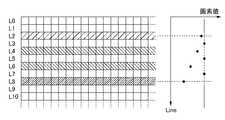
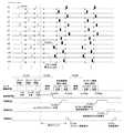
また、前述したように、センサアレイ上には常に暗電荷が発生するため、定期的に暗電荷のリセット動作を行う必要がある。そのため、図1のようにセンサアレイ上の各行(L0〜L10・・・)を順次駆動してスイッチ素子をONにし、対象行に接続される各画素の電荷をリセットするリセット走査(TC101)を行いながらバイアス線の電流量の変化を検出する。放射線の開始を検知した場合、その瞬間にリセット走査を実施していた行でリセット走査を停止し(TC102)、スイッチ素子をOFFにすることで、センサ駆動状態は放射線による画像信号電荷の蓄積動作状態となる(TC103)。この状態で、センサアレイにより放射線が検知される。 Further, as described above, since dark charges are always generated on the sensor array, it is necessary to periodically perform a dark charge reset operation. Therefore, as shown in FIG. 1, reset scanning (TC101) for sequentially driving each row (L0 to L10...) Of the sensor array to turn on the switch element and reset the electric charge of each pixel connected to the target row. The change in the amount of current of the bias line is detected while performing. When the start of radiation is detected, the reset scan is stopped at the line where the reset scan was performed at that moment (TC102), and the switch element is turned off. State (TC103). In this state, radiation is detected by the sensor array.
放射線の照射の完了後、再度センサアレイ上の各行を順次駆動してスイッチ素子をONにして、センサ駆動状態を画像信号電荷の出力動作状態として、各画素に蓄積された放射線画像信号の電荷の読み出し動作を行う(TC104)。 After the irradiation of the radiation is completed, each row on the sensor array is sequentially driven again to turn on the switch element, and the sensor driving state is set to the output operation state of the image signal charge, and the charge of the radiation image signal accumulated in each pixel is set. A read operation is performed (TC104).
この際、放射線の照射開始を検出した時点(TC102)でリセット動作をしていた行の各画素は、スイッチ素子がON状態のため、放射線の照射により発生した有用な画像信号電荷の一部が流出してしまう。 At this time, each pixel of the row that has performed the reset operation at the time when the start of radiation irradiation is detected (TC102) has a portion of useful image signal charges generated by the radiation irradiation because a switch element is in an ON state. Will leak out.
また、放射線照射装置において、放射線の照射を開始した時点では放射線の線量が瞬時に立ち上がらず、線量の立上がりが緩やかな場合には、放射線撮像装置での照射開始の検知が遅れる場合がある。この場合、実際に照射開始した時点から、放射線撮像装置が照射開始を検知した時点の行までの、複数の行(図1の場合はL2〜L7)をリセット走査してしまうため、複数行にわたり放射線照射により蓄積された有用な画像信号電荷の一部を流出してしまう。 Further, in the radiation irradiating apparatus, when the radiation irradiation is started, the radiation dose does not rise instantaneously, and when the rise of the dose is gentle, the detection of the irradiation start by the radiation imaging apparatus may be delayed. In this case, a plurality of rows (L2 to L7 in FIG. 1) from the time when the irradiation is actually started to the time when the radiation imaging apparatus detects the irradiation start are reset-scanned. Some of the useful image signal charges accumulated by the irradiation of the radiation are leaked.
図2のように、有用な電荷を流出した行(L2〜L7)の画素値は、前後の行(L0、L1、L8〜L10・・・)の画素値よりも電荷量が少なく、信頼のおけないものとなるため、データの補間を行う等の補正処理を行う必要がある。例えば、特許文献3では、前述のリセット走査を図3のように物理的に隣接しない行に関して順次リセット走査(TC301)を行いながら、放射線の照射開始の検出を待つように構成している。これにより、放射線検知時のデータが欠損する行(L2、L4、L6、L8)を、図4のように連続的に発生させないようにし、欠損行のデータを前後の正常な行のデータから補間することで、画像データの補正処理精度を向上させる方法が提案されている。例えば、欠損行がL2の場合は、前後の正常な行(L1、L3)を用いて補間処理を行うことが提案されている。 As shown in FIG. 2, the pixel values of the rows (L2 to L7) from which the useful charges flow out have smaller charge amounts than the pixel values of the preceding and following rows (L0, L1, L8 to L10,. Therefore, it is necessary to perform correction processing such as data interpolation. For example,
また、放射線撮像システムにおいては、撮像が正常にできたかどうか(再撮像が必要か否か)を早く判断するために、撮像実施後すぐに撮像画像が表示できることが求められる。しかしながら、撮像画像は、画像のオフセット成分を補正するオフセット補正処理等の各種画像補正処理や、表示装置まで画像を転送する転送時間が必要になるため、撮像から画像表示までの遅延時間(表示ディレイ時間)が発生する。 In addition, in the radiation imaging system, in order to quickly determine whether imaging has been performed normally (whether re-imaging is necessary), it is required that a captured image can be displayed immediately after imaging is performed. However, the captured image requires various image correction processes such as an offset correction process for correcting an offset component of the image, and a transfer time for transferring the image to the display device. Time) occurs.
この表示ディレイ時間を低減するため、オフセット補正をした後に、プレビュー画像を表示装置に転送する方法が、例えば特許文献4に記載されている。 A method of transferring a preview image to a display device after offset correction in order to reduce the display delay time is described in, for example,
特許文献2や特許文献3のように、放射線の照射開始を放射線撮像装置自体で検知する構成の場合、前述のように放射線の照射開始を検知した時点のリセット行、およびその付近の行において、放射線検知時のデータが欠損するため画像データが劣化してしまう。取得画像を縮小する等して、先行してプレビュー画像として表示する際に、放射線検知時の画像劣化が表示されると、撮像が正常に撮像できたか、操作者は判断できず、再撮像となる恐れがある。 In the case of a configuration in which the start of radiation irradiation is detected by the radiation imaging apparatus itself as in
そのため、画像データの劣化を修正するためには画像補正処理を行う必要があるが、プレビュー画像に対しても画像補正を行うと、補正処理のための時間ロスが発生し、高速に画像を表示することができないという課題がある。 Therefore, it is necessary to perform an image correction process to correct the deterioration of the image data. However, if the image correction is also performed on the preview image, a time loss for the correction process occurs, and the image is displayed at high speed. There is a problem that cannot be done.
かかる課題を解決するため、本発明は、画像の表示ディレイを低減し、かつ放射線検知時の画像劣化の補正処理を行うことなく、画像の表示が可能な放射線撮像技術を提供する。 In order to solve such a problem, the present invention provides a radiation imaging technique capable of reducing an image display delay and displaying an image without performing a process of correcting image deterioration during radiation detection.
本発明の一つの態様に係る放射線撮像装置は、各々が放射線の照射に応じた電荷を蓄積する複数の画素が2次元アレイ状に配置された放射線検出アレイと、
各々が前記複数の画素のうちの一部と接続された複数の走査ラインと、
前記複数の画素に蓄積された電荷を放出させるために、前記複数の走査ラインを順次選択するリセット走査を行わせるリセット走査手段と、
前記放射線の照射開始の検知を行うための照射検知手段と、
前記検知に応じて前記リセット走査を停止させ、かつ、前記複数の画素から前記放射線の照射に応じた電荷に基づく画像信号を得る制御を行う制御手段と、
前記画像信号に基づいて画像データを生成する生成手段と、
を有する放射線撮像装置であって、
前記複数の走査ラインは、複数の走査ライン群に分割され、前記複数の走査ライン群の各々は、互いに隣接しない複数の走査ラインで構成され、
前記リセット走査手段は、1回の走査で、前記複数の走査ライン群のうちの1つの走査ライン群を構成する走査ラインを順次選択し、複数回走査することにより、前記複数の走査ライン群に含まれる全ての走査ラインが選択されるように前記リセット走査を行わせ、
前記生成手段は、前記複数の走査ライン群のうちの前記リセット走査が停止されたときに選択されていた走査ラインを含む第一の走査ライン群を構成する走査ラインに接続された画素からの画像信号を用いることなく、該第一の走査ライン群を構成する走査ライン以外の走査ラインに接続された画素からの画像信号に基づいてプレビュー用画像データを生成し、前記第一の走査ライン群を構成する走査ラインに接続された画素からの画像信号を含む画像信号に基づいて本画像用画像データを生成することを特徴とする。
One of the radiation imaging apparatus according to the embodiment of the present invention, a radiation detector arrayin which a plurality of pixelsareplaced in atwo-dimensional array for storing chargescorresponding toeachof the radiation,
A plurality of scan lines each connected to a part of the plurality of pixels;
To outrelease the charge accumulated in theplurality ofpixels, and the resetscanning means for causing the reset scanfor sequentially selecting the plurality of scanning lines,
And irradiation detection meansfor performing detectionof the start of irradiation of said radiation,
Stopping the reset scan according to priordangerous knowledge,and a rowintends control means control for obtaining an image signalbased on the electriccharges corresponding to the irradiation of the radiationfrom said plurality of pixels,
Generating means for generating image data based on the image signal;
A radiation imaging devicehaving,
The plurality of scan lines are divided into a plurality of scan line groups, each of the plurality of scan line groups isconfigured by aplurality of scan linesthatare not adjacent toeach other ,
The resetscanning means, a single scan, sequentially selects the scanning linesconstituting one scan line groupsof the plurality of scan line groups, by scanning a plurality of times, tothe plurality of scanning line groupsall the scan lines includedso thatperformthe reset scan to be selectively,
Said generating means,the image fromthefirstpixel connected to the scan lines constituting the scan line group including a scanning line that is selected when the reset scanof the plurality of scanning line groupsis stoppedWithout using a signal, generate image data for preview based on image signalsfrom pixels connected toscan lines other than thescan linesconstitutingthe first scan linegroup , and generatethe first scan linegroup. The image data forthe main image is generated based onanimage signal including an image signal from a pixel connected toa scanning line to beconfigured .
本発明によれば、画像の表示ディレイを低減し、かつ放射線検知時の画像劣化を補正する処理を行うことなく、画像の表示が可能になる。 According to the present invention, it is possible to display an image without reducing a display delay of the image and without performing a process of correcting image deterioration at the time of radiation detection.
以下、図面を参照して、本発明の実施形態を例示的に詳しく説明する。ただし、実施形態に記載されている構成要素はあくまで例示であり、本発明の技術的範囲は、特許請求の範囲によって確定されるのであって、以下の個別の実施形態によって限定されるわけではない。 Hereinafter, embodiments of the present invention will be illustratively described in detail with reference to the drawings. However, the components described in the embodiments are merely examples, and the technical scope of the present invention is determined by the claims, and is not limited by the following individual embodiments. .
(第1実施形態)
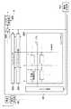
図5は本発明の実施形態にかかる放射線撮像システムの構成例を図示している。放射線撮像システムは放射線撮像装置1と、放射線撮像装置1を制御するコンソール3(情報処理装置)と、表示部4と、放射線を被写体に照射する放射線発生部500と、を有する。また、放射線撮像装置1は、放射線を検出し画像データを生成する放射線検出部2、放射線の照射開始や終了を検知する照射検知部101、撮像動作を制御する撮像制御部102を有する。(1st Embodiment)
FIG. 5 illustrates a configuration example of the radiation imaging system according to the embodiment of the present invention. The radiation imaging system includes a
撮像制御部102は、放射線検出部2の走査駆動を制御する駆動制御部103と、放射線検出部2からの画像データの取得制御を行う画像取得制御部107と、オフセット補正やプレビュー用画像生成等の信号処理を行う画像処理部108と、を有する。また、撮像制御部102は、放射線検出部2から取得した取得画像を記憶する記憶部111と、取得画像を外部のコンソール3に転送する等、コンソール3と間のデータ通信を制御する通信制御部114と、を有する。通信制御部114による放射線撮像装置1とコンソール3間のデータ通信は、例えば、無線LAN通信を用いることができる。尚、データ通信は無線LAN通信に限定されるものではなく、別の方式による無線通信や、ケーブルによる有線通信でも構わない。 The
駆動制御部103は、放射線検出部2を定期的、または任意のタイミングで、蓄積された暗電荷の放出(リセット)動作を行うためのリセット走査制御部105を有する。また、駆動制御部103は、放射線検出部2から画像を読み出すための駆動制御を行う読出し走査制御部106と、放射線の照射が開始された時点でリセット走査していた行番号等、照射検知時の情報を記憶するための照射検知時情報記憶部104を有する。 The
コンソール3は、放射線撮像装置1から転送される撮像画像を受信する等、放射線撮像装置1とコンソール3との間でのデータ通信を制御する通信制御部301を有する。また、コンソール3は、放射線撮像装置1から転送され受信した受信画像を記憶する記憶部302と、受信画像を補正するための画像処理部303とを有する。 The
撮像制御部102は、例えば、記憶部111に保存されているプログラム等を読み出し、これに基づいて放射線撮像装置1の全体的な制御を行う。放射線撮像装置1の制御は、例えば、ASIC等による制御信号発生回路(制御回路)により装置制御を行っても良いし、プログラムと制御回路との両方により放射線撮像装置1の全体的な制御が実現されても良い。 The
放射線検出部2は、放射線を電荷に変換する複数の変換素子が行方向の走査ラインに沿って配置され、複数の走査ラインが列方向に配置されている。例えば、TFTのようなスイッチ素子及び光電変換素子(放射線検知素子)を1つの画素として、この画素を2次元アレイ状に配置することにより構成されている。各画素上には、例えば、蛍光体が設けられて形成される。この場合、放射線検出部2に入射した放射線は蛍光体で可視光に変換され、変換された可視光が各画素の光電変換素子に入射し、各光電変換素子において、可視光に応じた電荷が生成される。なお、本実施形態では、上述した蛍光体、及び光電変換素子によって入射した放射線を電荷に変換する「変換素子」を構成例として説明する。ただし、本発明の趣旨は、この構成例に限定されるものではなく、例えば、蛍光体を設けずに、入射した放射線を直接電荷に変換する、いわゆる直接変換型の変換素子を用いることも可能である。放射線検出部2は、TFTのONとOFFの切替により、電荷の蓄積と電荷の読み出しを実施し、放射線画像を取得することができるものである。 In the
図6は放射線検出部2の構成例を示す図である。放射線検出部2の2次元センサアレイ上の行上の各画素は、ドライブ回路201により同時にアドレシングされ、行上の各画素の電荷はサンプルホールド回路202に保持される。その後、サンプルホールド回路202で保持された各画素の電荷(画素出力)はマルチプレクサ203を介して順次読出され、アンプ205により増幅された後、A/D変換器206によりディジタル値の画像データに変換される。各行の走査が終了する毎に、ドライブ回路201が2次元センサアレイ上の次の各行をドライブして順次走査を行い、最終的に全ての画素出力の電荷がディジタル値に変換される。これにより放射線画像データを読み出すことができる。この際、行上の各画素と接続する各列信号線に印加する電圧を特定値に固定しながら走査し、取得した電荷を読み捨てることにより、暗電荷が吐き出され、各画素に蓄積された暗電荷の放出(リセット)が行われる。これらの検出部の駆動、読出し動作等の制御は、駆動制御部103により行われる。 FIG. 6 is a diagram illustrating a configuration example of the
A/D変換器206によりディジタル値に変換された画像データが放射線照射により得られた放射線画像データである場合、放射線画像データは図5における撮像画像用メモリ112に格納される。また、放射線照射を行わず、各画素の暗電荷成分のみから取得したオフセット画像データ(オフセットデータ)の場合、オフセット画像データ(オフセットデータ)は図5におけるオフセット画像用メモリ113に格納される。 When the image data converted into digital values by the A /
画像処理部108に含まれるオフセット補正部110は、放射線画像データからオフセット画像データの成分を減算するオフセット補正を行うことで、不要な暗電荷成分を除去した撮像画像を取得することができる。 The offset
また、放射線の照射開始や終了を検知する照射検知部101は、画像を取得する放射線検出部2以外に、独立した放射線検出用のセンサを備えることも可能である。例えば、放射線検出部2のリセット走査中に吐き出される暗電流の量を監視することで、放射線検出部2自体で照射開始・終了検出を実現することが可能である。 In addition, the
オフセット画像データは、例えば、放射線撮像の後に取得し、オフセット補正部110オフセット補正を行う。尚、オフセット画像データの取得のタイミングは、放射線撮像の後に限定されるものではない。例えば、放射線撮像の前に、オフセット画像データを取得しても良いし、暗電荷成分の変動が少なければ、予め用意した1つのオフセット画像をオフセット補正処理に繰り返し用いても良い。 The offset image data is acquired, for example, after radiation imaging, and performs offset correction of the offset
また、放射線撮像装置1内の画像処理部108は、不要な暗電荷成分を除去した撮像画像を縮小する等して、プレビュー用画像を生成するプレビュー画像生成部109を持つ。例えば、プレビュー画像生成部は、放射線撮像画像を取得した後、オフセット補正前の撮像画像から先行してプレビュー画像を生成する。そして、プレビュー画像生成部109は、通信制御部114の制御の下、先行して生成したプレビュー画像をコンソール3に転送することで、先行して生成したプレビュー画像をコンソール3と接続する表示部4に表示可能とする。その後、オフセット補正部110でオフセット補正が実施された縮小しない撮像画像が、通信制御部114の制御の下、コンソール3に転送される。コンソール3と接続する表示部4は転送された撮像画像を本画像として表示する。 The
コンソール3の通信制御部301は放射線撮像装置1とのデータ送受信の制御を行い、例えばコンピュータ等に組み込まれたソフトウェアを操作することにより撮像制御部102とのデータ送受信を制御して、撮像部位や撮像条件等のパラメータを設定する。また、コンソール3の画像処理部303は放射線撮像装置1から受信した撮像画像を診断に適した形にするための画像処理を行う。また、コンソール3の記憶部302は放射線撮像装置1から受信した撮像画像を記憶する。表示部4は、コンソール3に送信された撮像画像データに基づいて、放射線検出部2から読み出された電荷に基づく放射線撮像画像や、操作UI等を表示する。 The
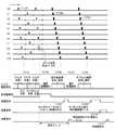
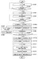
図7は本実施形態に係る放射線撮像システムにおける撮像シーケンスを示すタイミングチャートである。また、図8は、放射線撮像システムの撮像シーケンスの流れを説明するフローチャートである。図7、8を参照して放射線撮像システムの動作を説明する。 FIG. 7 is a timing chart showing an imaging sequence in the radiation imaging system according to the present embodiment. FIG. 8 is a flowchart illustrating a flow of an imaging sequence of the radiation imaging system. The operation of the radiation imaging system will be described with reference to FIGS.
放射線撮像装置が起動され、撮像待機状態になると、駆動制御部103のリセット走査制御部105は、放射線検出部2を構成する2次元センサアレイへの暗電荷の蓄積を防ぐために、定期的にリセット走査を実施する(図7のTC701、図8のS801)。この際、リセット走査制御部105は、2次元状のセンサアレイ上で物理的に隣接しない行(走査ライン)の変換素子を順次リセット走査(TC701)するようにリセット走査の対象となる走査ラインを選択し、選択した走査ラインの変換素子を順次駆動する。例えば、第一の部分リセット走査では2×n番目の行(n=0から1ずつ増加)を順次選択して走査し(L0、L2、L4・・)、第二の部分リセット走査では2×n+1番目の行(n=0から1ずつ増加)を順次選択して走査を行う(L1、L3、L5、・・)。そして、これら第一の部分リセット走査と第二の部分リセット走査を繰り返し、暗電荷の吐き出しを行いながら放射線の照射を待つ。尚、リセット走査の選択順は例示的なものであり、第二の部分リセット走査を先に行い、第二の部分リセット走査の後に、第一の部分リセット走査を行ってもよい。 When the radiation imaging apparatus is activated and enters an imaging standby state, the reset
また、本実施形態では、隣接しない行(走査ライン)として、1行ずつ順に飛ばして走査する例を示しているが、本発明の趣旨は、この例に限定するものではない。隣接しない行(走査ライン)として、例えば、2行ずつ順に飛ばして走査する場合、第一の部分リセット走査では3×n番目の行を走査し、第二の部分リセット走査では3×n+1番目の行を走査し、第三の部分リセット走査では3×n+2番目の行を走査する。 Further, in the present embodiment, an example in which scanning is performed by skipping one line at a time as a non-adjacent line (scanning line) is shown, but the gist of the present invention is not limited to this example. For example, when scanning is performed by skipping two rows in order as non-adjacent rows (scanning lines), the first partial reset scan scans the 3 × n-th row, and the second partial reset scan scans the 3 × n + 1-th row. The row is scanned, and the third partial reset scan scans the 3 × n + 2 row.
また、3行ずつ順に飛ばして走査する場合、第一の部分リセット走査では4×n番目の行を走査し、第二の部分リセット走査では4×n+1番目の行を走査し、第三の部分リセット走査では4×n+2番目の行を走査する。そして、第四の部分リセット走査では4×n+3番目の行を走査する。このように、任意の(m−1:mは2以上の整数)行ずつ飛ばしての走査を行い、第mの部分リセット走査までを繰り返しても良い。 In the case of scanning by skipping three rows in order, the first partial reset scan scans the 4 × n-th row, the second partial reset scan scans the 4 × n + 1-th row, and the third partial reset scan. In the reset scan, the 4 × n + 2th row is scanned. In the fourth partial reset scan, the (4 × n + 3) th row is scanned. In this manner, scanning may be performed by skipping an arbitrary (m−1: m is an integer of 2 or more) lines at a time, and the scanning up to the m-th partial reset scanning may be repeated.
また、隣接しない行であれば、一度に複数の行を選択してリセット走査を行ってもよい。例えば、3行ずつ順に飛ばして走査する場合において、第一の部分リセット走査と、第三の部分リセット走査と、を同時に選択してリセット走査を行ってもよい。また、第二の部分リセット走査と、第四の部分リセット走査と、を同時に選択してリセット走査を行ってもよい。 If the rows are not adjacent to each other, a plurality of rows may be selected at a time and reset scanning may be performed. For example, in a case where scanning is performed while skipping three lines at a time, the first partial reset scanning and the third partial reset scanning may be simultaneously selected to perform the reset scanning. Further, the reset scan may be performed by simultaneously selecting the second partial reset scan and the fourth partial reset scan.
ステップS802において、照射検知部101は、放射線発生部500から放射線の照射が開始されたか否かを判定する。照射検知部101が放射線の照射開始を検知しない場合(S802−No)、リセット走査が繰り返し実行される(S801)。 In step S802, the
ユーザの操作入力により放射線発生部500から放射線の照射が行われると、照射検知部101がこれを検知する。照射検知部101が放射線の照射開始を検知すると(S802−Yes)、リセット走査制御部105はリセット走査を停止させる(TC702、S803)。読出し走査制御部106は、2次元センサアレイ上の全てのTFTスイッチをOFFにして、2次元センサアレイ上の全ての画素を電荷蓄積状態にする(TC703、S804)。リセット走査停止により、センサ駆動状態は電荷蓄積動作状態となる。 When radiation is irradiated from the
このとき、駆動制御部103は、リセット走査停止時の2次元センサアレイの情報を照射検知時情報記憶部104に記憶する。すなわち、駆動制御部103は、リセット走査を停止させた際の行番号や、停止した際の部分リセット走査の種類、照射を検知した際の出力値の情報等を、照射検知時情報記憶部104に記憶する。図7において、リセット走査停止時の行番号は、8行目(L8)となる。ここで、部分リセット走査の種類とは、例えば、1行ずつ順に飛ばして走査、2行ずつ順に飛ばして走査、3行ずつ順に飛ばして走査など、リセット走査を行う際に隣接しない行(走査ライン)を選択するための情報をいう。 At this time, the
ステップS805において、照射検知部101は放射線の照射が終了したか否かを判定する。放射線の照射が終了していない場合(S805−No)、電荷蓄積動作(TC703、S804)を継続する。 In step S805, the
照射検知部101が放射線の照射の終了を検知すると(S805−Yes)、読出し走査制御部106は、2次元センサアレイ上の全てのTFTスイッチをONにして、2次元センサアレイ上の全ての画素を電荷出力状態にする。そして、放射線照射により蓄積された電荷を読み出すため、読出し走査制御部106は、2次元センサアレイ上の行を順次走査する読出し走査制御(TC704)を行い、放射線撮像された放射線画像データを取得する(S806)。ここで取得された放射線画像データは、撮像画像用メモリ112に記憶される。 When the
放射線画像データにおいては、背景技術で述べたように、実際の放射線の照射開始と照射検知部101の照射開始の検知までの検知遅れにより、一部の行の放射線画像データに劣化が発生し得る。プレビュー画像の表示において、画像データの劣化の影響を低減するため、読出し走査制御部106は、照射検知時情報記憶部104に記憶されているリセット走査停止時の2次元センサアレイの情報を取得する。そして、読出し走査制御部106は、放射線画像データのうち欠損が発生している画像データを特定する。 In the radiation image data, as described in the background art, deterioration may occur in the radiation image data of some rows due to a detection delay between the start of actual radiation irradiation and the detection of the irradiation start of the
図7においては、照射検知部101は、2×n番目の行の部分リセット走査中に放射線の照射開始を検知している。このため、図4に示すようにリセット走査停止時のリセット行(L8)および、それ以前の2×n番目の行(L2、L4、L6)の放射線画像データに欠損が発生していることになる。 In FIG. 7, the
なお、放射線の照射終了タイミングに関しては、照射検知部101により終了を検知しても良いし、撮像制御部102が特定の固定時間を待機することで照射終了とみなし、読み出し動作を開始しても良い。また、2次元センサアレイ自体で照射終了を検知する場合は、例えば、照射開始時にリセット走査していた行はTFTスイッチをOFFにせず、ONにしたままバイアス線に流れる電流量の監視を続けることで、照射終了を検知することが可能である。 Regarding the irradiation end timing of the radiation, the
次に、画像処理部108のプレビュー画像生成部109は、プレビュー画像の生成に用いる画像データを決定する。放射線照射開始時にリセット走査を行っていなかった第二の部分リセット走査で選択される行(2×n+1番目の行)の画像データに関しては、リセットによる有用な電荷の流出が無いため、画像劣化が発生していない。画像処理部108のプレビュー画像生成部109は照射開始検知時に実施していた部分リセット走査での選択行以外の行の画像データをプレビュー画像の生成に用いる画像データとして決定し、画像データからプレビュー画像を生成する(TC705、S807)。そして、通信制御部114は、プレビュー画像生成部109で生成されたプレビュー画像を診断用の本画像よりも先にコンソール3に転送する(TC705、S807)。 Next, the preview
コンソール3に転送されたプレビュー画像は、照射検知時の画像劣化がないため、劣化の画像補正処理が不要であり、表示部4に即時に表示することが可能である(TC706、S808)。 Since the preview image transferred to the
ここで、画像処理部108のプレビュー画像生成部109によるプレビュー画像生成時において、照射検知時の部分リセット走査での選択行以外のデータ(行(2×n+1番目の行)の画像データ)から、さらに間引き縮小してプレビュー画像を生成しても良い。プレビュー画像生成部109は、間引き縮小画像データを生成する際、例えば、図9に示すように画素を間引くことで、撮像画像を縮小した縮小プレビュー画像を生成してからコンソール3に転送することができる。図9において、例えば、L1行において、ハッチングを付した画素901は縮小プレビュー画像の生成(サンプリング)に用いられ、白抜きの画素902〜905は間引きの対象となる。 Here, when a preview image is generated by the preview
図9のように、物理的に連続する画素からサンプリングすることで、被写体における散乱放射線を除去するためのグリッドの配置に対応した周期信号(グリッド縞)のような、特定周波数ノイズの影響を間引きにより低減することができる。尚、プレビュー画像生成部109による縮小プレビュー画像の生成方法に関しては、図9に示す例に限定されるものではなく、別の間引き方法を用いることができる。例えば、縮小プレビュー画像の生成に用いる画素間については、補間処理を用いて縮小プレビュー画像を生成してもよい。縮小プレビュー画像の生成に用いる画素の画素値と補間処理とを組み合わせて縮小プレビュー画像を生成することも可能である。尚、間引きの割合は、図9に例示したものに限定されるものではなく、種々の割合を設定することが可能である。 As shown in FIG. 9, by sampling from physically continuous pixels, the influence of a specific frequency noise such as a periodic signal (grid stripe) corresponding to a grid arrangement for removing scattered radiation in a subject is thinned out. Can be reduced. Note that the method of generating the reduced preview image by the preview
放射線画像データの読み出し動作の完了後(S806)、読出し走査制御部106は2次元センサアレイ上の全ての画素のTFTスイッチを再びOFFにし、電荷蓄積状態にする(TC707、S809)。本ステップの処理は、先に説明したプレビュー画像の生成、転送処理(TC705、S807)、プレビュー画像の表示処理(TC706、S808)と並列に実行される。このように並列処理を行うことにより、プレビュー画像の生成、表示から、後に説明する診断用の本画像の生成、表示までの時間を短縮することが可能になる。 After the completion of the readout operation of the radiation image data (S806), the readout
ステップS810において、読出し走査制御部106は、放射線照射時の蓄積時間(TC703、S804)と同じ待機時間が経過したか判定する(待機時間経過)。この待機時間が経過していない場合(S810−No)、電荷蓄積動作を継続する。これにより暗電荷の蓄積が継続される。読出し走査制御部106は、放射線照射時の蓄積時間と同じ時間が経過したと判定すると(S810−Yes)、読出し走査制御部106は、2次元センサアレイ上の全てのTFTスイッチをONにして、2次元センサアレイ上の全ての画素を電荷出力状態にする。そして、読出し走査制御部106は、読み出し動作を実施し、暗電荷成分のみのオフセット画像データを取得する(TC708、S811)。 In step S810, the readout
その後、オフセット補正部110は、撮像画像用メモリ112に記憶されている放射線画像データの全データと、取得されたオフセット画像データとを用いてオフセット補正を行う(S812)。オフセット補正部110は、放射線画像データからオフセット画像データの成分を減算するオフセット補正により暗電荷成分を除去した撮像画像を取得する。 Thereafter, the offset
通信制御部114は、オフセット補正部110によりオフセット補正が施された撮像画像を本画像としてコンソール3に転送する(TC709、S813)。 The
プレビュー画像と異なり、撮像画像には照射検知時のリセット行付近のデータに劣化が発生するため、これを補正する必要がある。そこで、駆動制御部103は照射検知時情報記憶部104からリセット走査停止時の2次元センサアレイの情報(照射検知時の情報)を読み出し、通信制御部114は駆動制御部103により読み出された照射検知時の情報をコンソール3に転送する。 Unlike the preview image, the captured image deteriorates in the data near the reset line at the time of detecting the irradiation, and thus needs to be corrected. Therefore, the
コンソール3の画像処理部303は、照射検知時の情報から、リセット走査を停止させた際の行番号や、停止した際の部分リセット走査の種類(隣接しない行(走査ライン)の選択方法)、照射を検知した際の出力値の情報等を特定する。画像処理部303は、特定した情報を用いて、受信した撮像画像の欠損を補間するような画像補正し、各種診断に適した画像処理を施す(TC710、S814)。表示部4は、画像処理部303により画像処理が施された撮像画像を表示する(TC711、S815:本画像表示)。 The
なお、本実施形態では照射検知時の画像欠損の補正処理をコンソール3の画像処理部303にて実施しているが、これに限ったものではなく、放射線撮像装置1内の画像処理部108にて実施しても良い。この場合、照射検知時の情報をコンソール3に転送する必要はなく、画像処理部108がこの情報を使用して補正処理を行えばよい。 In the present embodiment, the correction processing of the image loss at the time of detecting the irradiation is performed by the
放射線の照射開始検知時のリセット行が、部分リセット走査により選択される行の先頭行付近だった場合、照射開始検知の遅れによる画像劣化が、その1つ前に実施していた部分リセット走査の最終行付近にも跨っている場合も生じ得る。図10に示すように、照射開始検知時のリセット行が第一の部分リセット走査時の先頭行(L0)の場合、その前に実施していた第二の部分リセット走査の最終行付近(L2(n−2)+1、L2(n−1)+1、L2n+1))にも跨っている場合が生じ得る。この場合、欠損が生じなければ、各画素は画素値1001を示す。第一の部分リセット走査時の先頭行(L0)が照射開始検知時のリセット行となる場合、先頭行(L0)の画素値1002は基準となる画素値1001に対して大きく低下する。第二の部分リセット走査の最終行付近のL2(n−2)+1行の画素値1003、L2(n−1)+1の画素値1004、L2n+1の画素値1005は、基準となる画素値1001に対して、次第に低くなっていき、先頭行(L0)の画素値1002に近づく。 If the reset row at the time of detecting the start of irradiation is near the first row of the row selected by the partial reset scan, image deterioration due to the delay of the detection of the start of irradiation may cause deterioration in the image of the partial reset scan performed immediately before that. There may be a case where it also straddles near the last line. As shown in FIG. 10, when the reset row at the time of detecting the start of irradiation is the first row (L0) at the time of the first partial reset scan, the vicinity of the last row (L2) of the second partial reset scan performed before that is performed. (N−2) +1, L2 (n−1) +1, L2n + 1)). In this case, if no loss occurs, each pixel has a pixel value of 1001. When the first row (L0) at the time of the first partial reset scan is the reset row at the time of detecting the start of irradiation, the
ただし、この場合でも、照射検知時にリセット走査を行っていなかった、第二の部分リセット走査で選択される行(2×n+1番目の行)の画像データからプレビュー画像を生成する。画像劣化として最も目立つのは、図2のように、列方向の画素値の変化が最も大きく、段差が発生するリセット停止時の行である(例えば、図2のL7)。図10の場合、プレビュー画像として使用する2×n+1番目の行の画像データにも、画像劣化が発生しているが、これらは段差として見えることはなく、端部に緩やかなグラデーションとして見えるため、プレビュー画像の表示に対する影響は軽微である。 However, also in this case, the preview image is generated from the image data of the row (2 × n + 1-th row) selected by the second partial reset scan, in which the reset scan was not performed when the irradiation was detected. The most noticeable image deterioration is a row at the time of reset stop where the step value occurs with the largest change in the pixel value in the column direction as shown in FIG. 2 (for example, L7 in FIG. 2). In the case of FIG. 10, image degradation also occurs in the image data of the 2 × n + 1th row used as the preview image, but these do not appear as steps, but appear as gentle gradations at the ends. The effect on the display of the preview image is insignificant.
本実施形態にかかる放射線撮像装置は、放射線を検出して電荷を蓄積する画素が2次元的に複数配置された放射線検出アレイ204と、該画素に蓄積された電荷をライン単位で順次放出させるための複数の走査ラインとを備える放射線検出部2を有する。 The radiation imaging apparatus according to the present embodiment has a
放射線撮像装置のリセット制御部として機能するリセット走査制御部105は、隣接しない走査ラインを順次選択してリセット走査を行わせる。照射検知部101は、リセット走査により放出された電荷に基づいて放射線の照射開始を検知する。 The reset
撮像制御部102は、照射開始の検知に応じてリセット走査を停止させ、かつ放射線の照射により放射線検出アレイ204の画素に蓄積された電荷を読み出し画像信号を得る制御を行う。 The
放射線撮像装置の生成部として機能するプレビュー画像生成部109は、放射線の照射中にリセット走査が行われた走査ラインからの画像信号を除いた画像信号に基づいて画像データを生成する。 また、放射線撮像装置の出力部として機能する通信制御部114は、画像データを外部の装置に出力する。 A preview
撮像制御部102は、画像信号を得る電荷の読み出しを、リセット走査が停止された走査ラインから開始する。 The
リセット走査制御部105は、所定の順序に従い走査ラインを順次選択し、撮像制御部102は、画像信号を得る電荷の読み出しを、リセット走査が停止された走査ラインから開始して所定の順序に従って読み出しを行なう。プレビュー画像生成部109は、画像信号が得られる総ライン数をNとしたとき、読み出しが開始された走査ラインから数えてN/2番目に読み出される走査ラインまでの画像信号に基づき画像データを生成する。 The reset
通信制御部114は、プレビュー画像生成部109により生成された画像データを出力した後に、放射線の照射中にリセット走査が行われた走査ラインからの画像信号を含むもう一つの画像データを外部の装置に出力する。 After outputting the image data generated by the preview
リセット走査制御部105は、リセット走査を偶数ラインと奇数ラインに分けて所定の順序で行なう。プレビュー画像生成部109は、リセット走査が停止したラインが偶数ラインである場合には奇数ラインの画像信号に基づいて画像データを生成し、リセット走査が停止したラインが奇数ラインである場合には偶数ラインの画像信号に基づいて画像データを生成する。 The reset
また、本実施形態にかかる放射線撮像装置は、放射線を検出して電荷を蓄積する画素が2次元的に複数配置された放射線検出アレイ204と、該画素に蓄積された電荷を放出させるための複数の走査ラインとを備える放射線検出部を有する放射線撮像装置である。 Further, the radiation imaging apparatus according to the present embodiment includes a
放射線撮像装置のリセット制御部として機能するリセット走査制御部105は、放射線検出アレイ204の画素に蓄積された電荷を順次放出させるリセット走査を行わせる。照射検知部101は、 リセット走査により放出された電荷に基づいて放射線の照射開始を検知する。撮像制御部102は、照射開始の検知に応じてリセット走査を停止させ、かつ放射線の照射により放射線検出アレイ204の画素に蓄積された電荷を読み出し画像信号を得る制御を行う。 A reset
放射線撮像装置の生成部として機能するプレビュー画像生成部109は、放射線の照射中にリセット走査が行われた画素からの画像信号を除いた画像信号に基づいて画像データを生成する。また、放射線撮像装置の出力部として機能する通信制御部114は、画像データを外部の装置に出力する。 A preview
(第2実施形態)
次に、本発明の第2実施形態にかかる放射線撮像システムについて説明する。本実施形態における放射線撮像システムの構成は、前述した第1実施形態の放射線撮像システムの構成と同様であるので、それぞれの構成要素の説明は省略する。(2nd Embodiment)
Next, a radiation imaging system according to a second embodiment of the present invention will be described. The configuration of the radiation imaging system according to the present embodiment is the same as the configuration of the radiation imaging system according to the above-described first embodiment, and a description of each component will be omitted.
図11、図12は、本実施形態に係る放射線撮像システムにおける撮像シーケンスを示すタイミングチャートである。図11、図12を参照して放射線撮像システムの動作を説明する。本実施形態においても、駆動制御部103のリセット走査制御部105は、放射線検出部2を構成する2次元センサアレイへの暗電荷の蓄積を防ぐために、定期的にリセット走査を実施する。リセット走査制御部105は、2次元センサアレイ上で物理的に隣接しない行(走査ライン)を順次リセット走査するようにリセット走査の対象となる走査ラインを選択し、選択した走査ラインの変換素子を順次駆動する(TC1101、S1201)。 FIGS. 11 and 12 are timing charts showing an imaging sequence in the radiation imaging system according to the present embodiment. The operation of the radiation imaging system will be described with reference to FIGS. Also in the present embodiment, the reset
ステップS1202において、照射検知部101が放射線の照射開始を検知しない場合(S1202−No)、リセット走査が繰り返し実行される(S1201)。照射検知部101が放射線の照射開始を検知すると(S1202−Yes)、リセット走査制御部105はリセット走査を停止させる(TC1102、S1203)。読出し走査制御部106は、2次元センサアレイ上の全てのTFTスイッチをOFFにして、2次元センサアレイ上の全ての画素を電荷蓄積状態にする(TC1103、S1204)。図11の例では、2n番目の行をリセット走査するリセット走査1の途中でリセット走査停止となっている。駆動制御部103は、リセット走査を停止させた際の行番号や、停止した際の部分リセット走査の種類、照射を検知した際の出力値の情報等を、照射検知時情報記憶部104に記憶する。ここで記憶された情報は、放射線画像データの読出しに使用される。 In step S1202, when the
ステップS1205において、照射検知部101は放射線の照射が終了したか否かを判定する。放射線の照射が終了していない場合(S1205−No)、電荷蓄積動作(TC1203、S1204)を継続する。 In step S1205, the
照射検知部101が放射線の照射の終了を検知すると(S1205−Yes)、読出し走査制御部106は、2次元センサアレイ上の全てのTFTスイッチをONにして、2次元センサアレイ上の全ての画素を電荷出力状態にする。そして、放射線照射により蓄積された電荷を読み出すため、読出し走査制御部106は、2次元センサアレイ上の行を順次走査する読出し走査制御(TC1104a、1104b)を行い、放射線撮像された放射線画像データを取得する(S1206)。 When the
撮像画像の読み出し走査を実施する際、照射検知時の部分リセット走査で選択する行(例えば、2n番目の行)以外の行のみ(例えば、2n+1番目の行)を選択し、先に読出し走査を実施する。 When performing a read scan of a captured image, only rows (for example, the 2n + 1th row) other than the row (for example, the 2nth row) selected by the partial reset scan at the time of irradiation detection are selected, and the read scan is performed first. carry out.
例えば、図10の場合には、2×n番目の行を順次リセット走査する第一の部分リセット走査時に照射開始が検知されている。読み出し走査時には、2n番目の行以外の行である2×n+1番目の行から先に放射線画像データを順次読み出す、部分読出し走査を行う(TC1104a、S1206a:第一の部分読出し走査)。 For example, in the case of FIG. 10, the irradiation start is detected at the time of the first partial reset scanning in which the 2 × n-th row is sequentially reset scanned. At the time of readout scanning, partial readout scan is performed in which radiation image data is sequentially read out first from the 2 × n + 1th row other than the 2nth row (TC1104a, S1206a: first partial readout scan).
2×n+1番目の行からの放射線画像データの読出しの終了後、2×n番目の行から放射線画像データを順次読み出す、部分読出し走査を行う(TC1104b、S1206b:第二の部分読出し走査)。ここで、第一の部分読出し走査(TC1104a、S1206a)で得られる放射線画像データには、照射検知時の放射線画像データに劣化は存在しない。そこで、第一の部分読出し走査(TC1104a、S1206a)の終了後、第二の部分読出し走査との並列処理により、プレビュー画像生成部109は第一の部分読出し走査で得た放射線画像データからプレビュー画像を生成する(TC1105、S1207)。そして、通信制御部114はプレビュー画像生成部109で生成されたプレビュー画像を診断用の本画像よりも先にコンソール3に転送する(TC1105、S1207)。 After the reading of the radiation image data from the 2 × n + 1-th row is completed, a partial reading scan is performed to sequentially read the radiation image data from the 2 × n-th row (TC1104b, S1206b: second partial reading scan). Here, the radiation image data obtained by the first partial readout scan (TC1104a, S1206a) has no deterioration in the radiation image data at the time of irradiation detection. Therefore, after the first partial reading scan (TC1104a, S1206a) is completed, the preview
コンソール3に転送されたプレビュー画像は、照射検知時の画像劣化がないため、劣化の画像補正処理が不要であり、表示部4に即時に表示することが可能である(TC1106、S1208)。これにより、センサアレイ全行の読み出し完了を待つことなく、先行してプレビュー画像を転送することが可能になる。第1実施形態に比べ、プレビュー画像表示までのディレイ時間をより低減することが可能になる。 Since the preview image transferred to the
2×n番目の行からの放射線画像データの読み出し動作の完了後(TC1104b、S1206b)、読出し走査制御部106は2次元センサアレイ上の全ての画素のTFTスイッチを再びOFFにし、電荷蓄積状態にする(TC1107、S1209)。 After the completion of the reading operation of the radiation image data from the 2 × n-th row (TC1104b, S1206b), the reading
ステップS1210において、読出し走査制御部106は、放射線照射時の蓄積時間(TC1103、S1204)と同じ時間が経過したか判定する(待機時間経過)。この待機時間が経過していない場合(S1210−No)、電荷蓄積動作を継続する。これにより暗電荷の蓄積が継続される。読出し走査制御部106は放射線照射時の蓄積時間と同じ時間が経過したと判定すると(S1210−Yes)、読出し走査制御部106は2次元センサアレイ上の全てのTFTスイッチをONにして、2次元センサアレイ上の全ての画素を電荷出力状態にする。そして、読出し走査制御部106は、読み出し動作を実施し、暗電荷成分のみのオフセット画像データを取得する。 In step S1210, the readout
読み出し走査時において、読出し走査制御部106は、2n番目の行以外の行である2×n+1番目の行から先にオフセット画像データを順次読み出す(TC1108a、S1211a)。 At the time of read scanning, the read
2×n+1番目の行からのオフセット画像データの読出しの終了後、読出し走査制御部106は、2×n番目の行からオフセット画像データを順次読み出す(TC1108b、S1211b)。 After the reading of the offset image data from the (2 × n + 1) th row is completed, the readout
オフセット補正部110は、撮像画像用メモリ112に記憶されている放射線画像データの全データと取得したオフセット画像データとを用いてオフセット補正を行う(S1212)。オフセット補正部110は、放射線画像データからオフセット画像データの成分を減算するオフセット補正により暗電荷成分を除去した撮像画像を取得する。通信制御部114は、オフセット補正部110によりオフセット補正が施された撮像画像を本画像としてコンソール3に転送する(TC1109、S1213)。 The offset
駆動制御部103は照射検知時情報記憶部104から照射検知時の情報を読み出し、通信制御部114は駆動制御部103により読み出された照射検知時の情報をコンソール3に転送する。 The
コンソール3の画像処理部303は、照射検知時の情報から、リセット走査を停止させた際の行番号や、停止した際の部分リセット走査の種類(隣接しない行(走査ライン)の選択方法)、照射を検知した際の出力値の情報等を特定する。画像処理部303は、特定した情報を用いて受信した撮像画像の欠損を補間するような画像補正し、各種診断に適した画像処理を施す(TC1110、S1214)。表示部4は、画像処理部303により画像処理が施された撮像画像を表示する(TC1111、S1215:本画像表示)。 The
上述の各実施形態によれば、プレビュー画像の表示ディレイを低減し、かつ放射線検知時の画像劣化を補正する処理を行うことなく、プレビュー画像の表示が可能になる。 According to each of the above-described embodiments, the preview image can be displayed without reducing the display delay of the preview image and without performing the process of correcting the image deterioration at the time of radiation detection.
放射線の照射開始を待機する際のリセット走査を2次元センサアレイ上で隣接しない行で順次実施する。放射線照射開始の検知時に部分リセット走査していた行の画像データのみに欠損が発生し、照射開始時のリセット走査で選択されていない行の画像データには欠損が発生しない。 The reset scan when waiting for the start of radiation irradiation is sequentially performed on non-adjacent rows on the two-dimensional sensor array. Loss occurs only in the image data of the row that has been subjected to the partial reset scan at the time of detection of the start of irradiation, and no loss occurs in the image data of the row that is not selected in the reset scan at the start of irradiation.
これを利用し、欠損が発生していない行から得られる画像データのみを使用してプレビュー画像を生成し、表示部に転送することで、プレビュー画像に対して画像劣化の補正処理を行うことなくプレビュー画像を表示することが可能になる。これにより、プレビュー画像の表示までの遅延時間(表示ディレイ)を低減でき、画素値の欠損の影響が含まれないプレビュー画像を表示することが可能になる。 By utilizing this, a preview image is generated using only image data obtained from a line where no loss has occurred, and transferred to the display unit, without performing image deterioration correction processing on the preview image. A preview image can be displayed. As a result, the delay time (display delay) until the display of the preview image can be reduced, and it is possible to display the preview image that is not affected by the loss of the pixel value.
(第3実施形態)
次に、第3実施形態にかかる放射線撮像装置について説明する。放射線撮像装置は、放射線を電荷に変換する複数の変換素子が2次元に配置された放射線検出アレイと、変換素子を選択するための複数の走査ラインを備える放射線検出部を有する。(Third embodiment)
Next, a radiation imaging apparatus according to a third embodiment will be described. The radiation imaging apparatus has a radiation detection array in which a plurality of conversion elements for converting radiation into electric charges are two-dimensionally arranged, and a radiation detection unit including a plurality of scanning lines for selecting the conversion elements.
リセット走査制御部は、隣接しない走査ラインを順次選択することにより走査ラインに対応する変換素子に蓄積された電荷を放出するリセット走査を行うリセット走査制御を行う。照射検知部は、リセット走査中の放射線の照射開始を検知する。読出し制御部は、照射検知部による照射開始の検知に応じてリセット走査を停止させるとともに、放射線の照射により変換素子に蓄積された電荷を読出し、電荷に基づく画像データを取得する。プレビュー画像生成部109(生成部)は、放射線の照射中にリセット走査が行われていない走査ラインに対応する画像データに基づいてプレビュー画像を生成する。通信制御部(出力部)は、プレビュー画像生成部(生成部)により生成されたプレビュー画像を外部の装置に出力する。 The reset scanning control section performs reset scanning control for sequentially selecting non-adjacent scanning lines to perform reset scanning for releasing charges accumulated in the conversion elements corresponding to the scanning lines. The irradiation detection unit detects the start of irradiation of radiation during reset scanning. The reading control unit stops the reset scanning in response to the detection of the irradiation start by the irradiation detecting unit, reads out the electric charge accumulated in the conversion element by the irradiation of the radiation, and obtains image data based on the electric charge. The preview image generation unit 109 (generation unit) generates a preview image based on image data corresponding to a scan line on which reset scanning has not been performed during irradiation of radiation. The communication control unit (output unit) outputs the preview image generated by the preview image generation unit (generation unit) to an external device.
プレビュー画像生成部は、読出し制御部により読み出された画像データから、放射線の照射開始から放射線の照射検知までの間にリセット走査が行われていた走査ラインに対応する画像データを除いた画像データに基づいてプレビュー画像を生成する。 The preview image generation unit is configured to remove, from the image data read by the read control unit, image data corresponding to a scan line on which reset scanning has been performed from the start of radiation irradiation to the detection of radiation irradiation. A preview image is generated based on.
リセット走査制御部および読出し制御部は、複数の走査ラインを互いに隣接しない複数の走査ライン群に分け、複数の走査ライン群のうちの一のライン群の走査を実行した後に他のライン群についての走査を実行する。 The reset scan control unit and the read control unit divide the plurality of scan lines into a plurality of scan line groups that are not adjacent to each other, and perform a scan of one of the plurality of scan line groups, and then execute the scan for another line group. Perform a scan.
読出し制御部は、放射線の照射が検知された際にリセット走査が行われていた走査ライン群以外の走査ラインの変換素子に蓄積された電荷を先行して読出す。プレビュー画像生成部(生成部)は、先行して読み出された、走査ラインの変換素子に蓄積された電荷に対応する画像データに基づいて、プレビュー画像を生成する。 The readout control unit reads out the charge accumulated in the conversion elements of the scan lines other than the scan line group on which the reset scan was performed when the irradiation of the radiation was detected. The preview image generation unit (generation unit) generates a preview image based on the image data corresponding to the electric charge stored in the conversion element of the scan line, which is read in advance.
複数の走査ライン群は、放射線検出アレイの配置として偶数番目に配置されている走査ラインを含む第一のライン群と、奇数番目に配置されている走査ラインを含む第二のライン群と、を含む。通信制御部(出力部)は、例えば、プレビュー画像生成部(生成部)により生成されたプレビュー画像を無線で送信する無線通信回路を有する。尚、プレビュー画像の送信は、無線通信に限定されるものではなく、ケーブルによる有線通信でも構わない。 The plurality of scan line groups include a first line group including scan lines arranged in even numbers as an arrangement of the radiation detection array, and a second line group including scan lines arranged in odd numbers. Including. The communication control unit (output unit) includes, for example, a wireless communication circuit that wirelessly transmits the preview image generated by the preview image generation unit (generation unit). The transmission of the preview image is not limited to the wireless communication, but may be a wired communication using a cable.
(第4実施形態)
図13を参照しながら第4実施形態を説明する。先述の実施形態とは、駆動のされ方が異なるもので、駆動の制御主体や駆動される対象は先述の実施形態と同様であるので説明を省略する。この実施形態では、蓄積動作(TC1303)に入った後、放射線画像読み出し動作を、蓄積動作の直前に走査していた行の次の行から行う。図13に示す例では、L8行をリセット走査した後にL9行から放射線画像読み出し動作を開始し、2n+1行走査、2n行走査が行われる。(Fourth embodiment)
A fourth embodiment will be described with reference to FIG. The driving method is different from that of the above-described embodiment, and the control subject of the driving and the driven object are the same as those of the above-described embodiment, and the description thereof will be omitted. In this embodiment, after entering the accumulation operation (TC1303), the radiation image reading operation is performed from the row following the row scanned immediately before the accumulation operation. In the example illustrated in FIG. 13, the radiation image reading operation is started from the L9 row after the reset scanning of the L8 row, and the 2n + 1-row scanning and the 2n-row scanning are performed.
また、図11の例に比べ、2n行と2n+1行の間のラインごとの蓄積時間の差を小さくできるため、よりノイズの少ない画像を得ることができる。 Further, as compared with the example of FIG. 11, the difference in the accumulation time between the 2n-th row and the 2n + 1-th row can be reduced, so that an image with less noise can be obtained.
その後、2n+1行を最後まで走査すると、初めに戻り残りの2n+1行を走査する(停止行の−1まで)。L9、L11・・・と走査し、その後L1、L3、L5、L7を走査する。これにより、2n+1行走査が完了する。かかる2n+1行走査により得られる画像信号は、先述の実施例と同様に外部の装置に転送される。もちろん、蓄積動作前に最後にリセット走査された行が2n+1行(偶数行)であれば、放射線画像読み出し動作は2n行から行われる。 After that, when the 2n + 1 rows are scanned to the end, the process returns to the beginning and scans the remaining 2n + 1 rows (up to the -1 stop row). .., And then scan L1, L3, L5, L7. This completes the 2n + 1 row scanning. The image signal obtained by the 2n + 1 row scanning is transferred to an external device in the same manner as in the above-described embodiment. Of course, if the last row subjected to the reset scan before the accumulation operation is 2n + 1 rows (even rows), the radiation image reading operation is performed from 2n rows.
放射線画像読み出し動作後の蓄積動作(TC1307)が行われた後、オフセット画像読み出し動作も、上述の放射線画像読み出し動作と同様に行われる。これにより、放射線画像とオフセット画像とで蓄積時間を近づけ、放射線画像のダーク成分を適切に補正することができる。 After the accumulation operation (TC1307) after the radiation image reading operation is performed, the offset image reading operation is also performed in the same manner as the above-described radiation image reading operation. As a result, the accumulation time between the radiation image and the offset image can be reduced, and the dark component of the radiation image can be appropriately corrected.
なお、放射線画像読み出し動作と蓄積動作(TC1307)の間に、リセット走査(TC1301)のうち蓄積動作の直前に行われた2n+1行走査と2n行走査の途中までの走査を行うこととすれば、各行の蓄積時間はより放射線画像のそれに近づく。 Note that, between the radiation image reading operation and the accumulation operation (TC1307), if the 2n + 1-line scanning and the 2n-line scanning performed immediately before the accumulation operation in the reset scanning (TC1301) are to be performed, The storage time of each row is closer to that of the radiographic image.
またさらに、放射線画像読み出し動作と蓄積動作(TC1307)の間に、画素に逆バイアスをかけた上でのリセット走査を行い、かつリセット時と同様の順バイアスをかけた上でのリセット走査を行う(リフレッシュ動作)を行う。これによれば、特にMIS型のセンサにおいてX線検出により低下するダイナミックレンジを回復させ、良好なオフセット画像を得ることができる。 Further, between the radiation image reading operation and the accumulation operation (TC1307), reset scanning is performed after applying a reverse bias to the pixel, and reset scanning is performed after applying the same forward bias as at the time of resetting. (Refresh operation). According to this, it is possible to recover a dynamic range reduced by X-ray detection, particularly in a MIS sensor, and obtain a good offset image.
また、蓄積動作前に最後にリセット走査されたL8行の次の行から読み出しを開始しなくとも、例えばL11行やL13行から読み出しを開始するとしてもよく。必ずしもL8行の次の行から読み出しを開始しなくてもよい。 Further, the reading may not be started from the row next to the L8 row that was last reset-scanned before the accumulation operation, but may be started from the L11 row or the L13 row, for example. It is not always necessary to start reading from the row following the L8 row.
(第5実施形態)
図14を参照しながら第5実施形態を説明する。先述の実施形態とは、駆動のされ方が異なるもので、駆動の制御主体や駆動される対象は先述の実施形態と同様であるので説明を省略する。この実施形態では、リセット走査において複数の行を同時に走査する。図14に示す例では、L0、L2、L4、L6の計4つの行の行選択線に接続するTFTを同時にオンする。駆動回路をシフトレジスタで構成する場合には、L0、L2、L4、L6までの操作を可能な限り短い時間で走査し、L0、L2、L4、L6が同時にON状態となるように走査する。この場合、各行の走査タイミングは若干ずれることとなるが、バイアス線に流れる電流は厳密に同時ONした場合と実質的に同じように増やすことができるので、検出感度の向上に寄与する。ここで、検出感度とは、X線照射が実際に開始されてから検知されるまでの間の時間で例えば定義される。また、別の観点では、所定の時間内に検知できるX線の強さの最低値で定義される。ここでいう強さとは例えば単位時間当たりの線量である。(Fifth embodiment)
A fifth embodiment will be described with reference to FIG. The driving method is different from that of the above-described embodiment, and the control subject of the driving and the driven object are the same as those of the above-described embodiment, and the description thereof will be omitted. In this embodiment, a plurality of rows are simultaneously scanned in the reset scan. In the example shown in FIG. 14, the TFTs connected to a total of four row selection lines L0, L2, L4, and L6 are simultaneously turned on. When the drive circuit is formed by a shift register, the operation up to L0, L2, L4, and L6 is scanned in the shortest possible time, and scanning is performed so that L0, L2, L4, and L6 are simultaneously turned on. In this case, although the scanning timing of each row is slightly shifted, the current flowing through the bias line can be increased substantially in the same manner as in the case of strictly simultaneous ON, thereby contributing to improvement in detection sensitivity. Here, the detection sensitivity is defined, for example, as the time from when X-ray irradiation is actually started to when it is detected. From another viewpoint, it is defined by the minimum value of the X-ray intensity that can be detected within a predetermined time. Here, the intensity is, for example, a dose per unit time.
また、この実施形態では、放射線画像読み出し動作に置いて、2n+1行走査と2n行走査との間に待機時間を設け、その間に2n+1行走査により得られた画像信号を外部に転送する。かかる待機時間は、2n+1行操作により得られる画像信号の転送が完了するまで、つまり転送先からのACK信号が受信されるか、転送に関するタイムアウト時間を経過するかが判定されることに応じて終了するよう制御される。かかる判定が行われる事に応じて2n行の走査が開始されることとなる。かかる待機時間t_waitの情報はメモリに記憶される。 Further, in this embodiment, in the radiation image reading operation, a standby time is provided between the 2n + 1th row scanning and the 2nth row scanning, and during that time, the image signal obtained by the 2n + 1th row scanning is transferred to the outside. The standby time ends until the transfer of the image signal obtained by the 2n + 1-row operation is completed, that is, when it is determined whether the ACK signal is received from the transfer destination or the timeout period for the transfer has elapsed. Is controlled. Scanning of 2n rows is started in response to such determination. Information on the waiting time t_wait is stored in the memory.
このように、放射線画像読み出し動作と画像転送とを同じタイミングでは行わないようにすることで、読み出される画像信号に重畳する通信ノイズを減らすことができる。かかる駆動は無線で画像転送を行う場合にはより効果が大きい。また2n+1行走査と2n行走査との間に画像転送を行うことで、通信ノイズの影響を低減しつつ結果的にはプレビュー画像の表示をより迅速に行わせることができる。 As described above, by not performing the radiation image reading operation and the image transfer at the same timing, it is possible to reduce communication noise superimposed on the read image signal. Such driving is more effective when wirelessly transferring images. Further, by performing the image transfer between the 2n + 1-row scanning and the 2n-row scanning, the preview image can be displayed more quickly while reducing the influence of the communication noise.
そのほか、オフセット画像読み出し動作時にも、メモリに記憶されたt_waitだけ、2n+1行走査と2n行走査の間に待機時間を設けることとする。2n+1行走査が終了後、t_waitだけ経過した後に2n行走査を開始するように制御する。 In addition, at the time of the offset image reading operation, a waiting time is provided between 2n + 1-row scanning and 2n-row scanning by t_wait stored in the memory. After the scanning of 2n + 1 rows is completed, control is performed so that scanning of 2n rows is started after elapse of t_wait.
なお、上述の実施形態は適宜組み合わせることとしてもよい。例えば別の実施形態で、図13のように蓄積動作前に最後にリセット走査された行の次の行から放射線画像読み出し動作を開始する場合であっても、図14のように放射線画像読み出し動作の2n+1行走査と2n行走査との間に待機時間を設定する。そして、2n+1行走査により得られる画像信号の転送中に走査乃至走査により得られる画像信号アンプによる増幅、AD変換などの読み出しが行われないようにする。 Note that the above embodiments may be appropriately combined. For example, in another embodiment, even when the radiation image reading operation is started from the row next to the row that was last reset scanned before the accumulation operation as shown in FIG. 13, the radiation image reading operation is started as shown in FIG. A standby time is set between 2n + 1 row scanning and 2n row scanning. Then, during transfer of the image signal obtained by the 2n + 1-row scanning, scanning or amplification by the image signal amplifier obtained by the scanning, and reading such as AD conversion are not performed.
その他の実施形態では図14のように複数行を同時に走査する場合であっても、放射線画像読み出し動作と転送とを並行して行うようにタイミング制御する。そのほか、適宜組み合わせが可能である。 In other embodiments, even when a plurality of rows are simultaneously scanned as shown in FIG. 14, the timing is controlled so that the radiation image reading operation and the transfer are performed in parallel. In addition, appropriate combinations are possible.
(その他の実施形態)
また、本発明は、以下の処理を実行することによっても実現される。即ち、上述した実施形態の機能を実現するソフトウェア(プログラム)を、ネットワーク又は各種記憶媒体を介してシステム或いは装置に供給し、そのシステム或いは装置のコンピュータ(またはCPUやMPU等)がプログラムを読み出して実行する処理である。(Other embodiments)
The present invention is also realized by executing the following processing. That is, software (program) for realizing the functions of the above-described embodiments is supplied to a system or apparatus via a network or various storage media, and a computer (or CPU, MPU, or the like) of the system or apparatus reads the program and reads the program. This is the process to be performed.
2:放射線検出部、101:照射検知部、102:撮像制御部、103:駆動制御部、108:画像処理部 2: radiation detection unit, 101: irradiation detection unit, 102: imaging control unit, 103: drive control unit, 108: image processing unit
Claims (14)
Translated fromJapanese各々が前記複数の画素のうちの一部と接続された複数の走査ラインと、
前記複数の画素に蓄積された電荷を放出させるために、前記複数の走査ラインを順次選択するリセット走査を行わせるリセット走査手段と、
前記放射線の照射開始の検知を行うための照射検知手段と、
前記検知に応じて前記リセット走査を停止させ、かつ、前記複数の画素から前記放射線の照射に応じた電荷に基づく画像信号を得る制御を行う制御手段と、
前記画像信号に基づいて画像データを生成する生成手段と、
を有する放射線撮像装置であって、
前記複数の走査ラインは、複数の走査ライン群に分割され、前記複数の走査ライン群の各々は、互いに隣接しない複数の走査ラインで構成され、
前記リセット走査手段は、1回の走査で、前記複数の走査ライン群のうちの1つの走査ライン群を構成する走査ラインを順次選択し、複数回走査することにより、前記複数の走査ライン群に含まれる全ての走査ラインが選択されるように前記リセット走査を行わせ、
前記生成手段は、前記複数の走査ライン群のうちの前記リセット走査が停止されたときに選択されていた走査ラインを含む第一の走査ライン群を構成する走査ラインに接続された画素からの画像信号を用いることなく、該第一の走査ライン群を構成する走査ライン以外の走査ラインに接続された画素からの画像信号に基づいてプレビュー用画像データを生成し、前記第一の走査ライン群を構成する走査ラインに接続された画素からの画像信号を含む画像信号に基づいて本画像用画像データを生成することを特徴とする放射線撮像装置。And the radiation detecting arrayin which a plurality of pixelsareplaced in atwo-dimensional array for storingcharge, eachcorresponding to the irradiation of radiation,
A plurality of scan lines each connected to a part of the plurality of pixels;
To outrelease the charge accumulated in theplurality ofpixels, and the resetscanning means for causing the reset scanfor sequentially selecting the plurality of scanning lines,
And irradiation detection meansfor performing detectionof the start of irradiation of said radiation,
Stopping the reset scan according to priordangerous knowledge,and a rowintends control means control for obtaining an image signalbased on the electriccharges corresponding to the irradiation of the radiationfrom said plurality of pixels,
Generating means for generating image data based on the image signal;
A radiation imaging devicehaving,
The plurality of scan lines are divided into a plurality of scan line groups, each of the plurality of scan line groups isconfigured by aplurality of scan linesthatare not adjacent toeach other ,
The resetscanning means, a single scan, sequentially selects the scanning linesconstituting one scan line groupsof the plurality of scan line groups, by scanning a plurality of times, tothe plurality of scanning line groupsall the scan lines includedso thatperformthe reset scan to be selectively,
Said generating means,the image fromthefirstpixel connected to the scan lines constituting the scan line group including a scanning line that is selected when the reset scanof the plurality of scanning line groupsis stoppedWithout using a signal, generates image data for preview based on image signalsfrom pixels connected toscan lines other than thescan linesconstitutingthe first scan linegroup , and generatesthe first scan linegroup. A radiation imaging apparatus, whereinmain image data is generated based onanimage signal including an image signal from a pixel connected toa scanning line to beconfigured .
各々が前記複数の画素のうちの一部と接続された複数の走査ラインと、
前記複数の画素に蓄積された電荷を放出させるために、前記複数の走査ラインを順次選択するリセット走査を行わせるリセット走査手段と、
前記放射線の照射開始の検知を行うための照射検知手段と、
前記検知に応じて前記リセット走査を停止させ、かつ、前記複数の画素から前記放射線の照射に応じた電荷に基づく画像信号を得る制御を行う制御手段と、
前記画像信号に基づいて画像データを生成する生成手段と、
を有する放射線撮像装置であって、
前記複数の走査ラインは、複数の走査ライン群に分割され、前記複数の走査ライン群の各々は、互いに隣接しない複数の走査ラインで構成され、
前記リセット走査手段は、1回の走査で、前記複数の走査ライン群のうちの1つの走査ライン群を構成する走査ラインを順次選択し、複数回走査することにより、前記複数の走査ライン群に含まれる全ての走査ラインが選択されるように前記リセット走査を行わせ、
前記生成手段は、前記複数の走査ライン群のうち、放射線が照射されている間に選択されていた走査ラインを含む第二の走査ライン群を構成する走査ラインに接続された画素からの画像信号を用いることなく、該第二の走査ライン群を構成する走査ライン以外の走査ラインに接続された画素からの画像信号に基づいてプレビュー用画像データを生成し、前記第二の走査ライン群を構成する走査ラインに接続された画素からの画像信号を含む画像信号に基づいて本画像用画像データを生成することを特徴とする放射線撮像装置。And the radiation detecting arrayin which a plurality of pixelsareplaced in atwo-dimensional array for storingcharge, eachcorresponding to the irradiation of radiation,
A plurality of scan lines each connected to a part of the plurality of pixels;
To outrelease the charge accumulated in theplurality ofpixels, and the resetscanning means for causing the reset scanfor sequentially selecting the plurality of scanning lines,
And irradiation detection meansfor performing detectionof the start of irradiation of said radiation,
Stopping the reset scan according to priordangerous knowledge,and a rowintends control means control for obtaining an image signalbased on the electriccharges corresponding to the irradiation ofthe radiationfrom saidplurality of pixels,
Generating means for generating image data based on the image signal;
A radiation imaging devicehaving,
The plurality of scan lines are divided into a plurality of scan line groups, each of the plurality of scan line groups isconfigured by aplurality of scan linesthatare not adjacent toeach other,
The resetscanning means, a single scan, sequentially selects the scanning linesconstituting one scan line groupsof the plurality of scan line groups, by scanning a plurality of times, tothe plurality of scanning line groupsall the scan lines includedso thatperformthe reset scan to be selectively,
It said generating means,said plurality of scan line groups, an image signal fromthe second pixel connected to the scan linesconstituting the scan line group including a scan line that has been selected while the radiation is irradiatedWithout using , generating image data for previewbased on image signals from pixels connected to scan lines other than the scan linesconstitutingthe second scan linegroup,the second scan linegroup A radiation imaging apparatus that generates main image databased on an image signal including an image signal from a pixel connected toa scan line to be scanned .
前記生成手段は、前記リセット走査が停止したラインが偶数ラインである場合には奇数ラインの画像信号に基づいて、前記プレビュー用画像データを生成し、前記リセット走査が停止したラインが奇数ラインである場合には偶数ラインの画像信号に基づいて、前記プレビュー用画像データを生成することを特徴とする請求項1又は2に記載の放射線撮像装置。The scan line group includes a scan line group consisting of even lines and a scan line group consisting of odd lines,
The generation unit generates the preview image data based on an image signal of an odd line when the line at which the reset scan is stopped is an even line, and the line at which the reset scan is stopped is an odd line. 3. The radiation imaging apparatus according to claim 1, wherein in the case, the preview image data is generated based on an image signal of an even-numbered line. 4.
前記複数の画素に蓄積された電荷を放出させるために前記複数の走査ラインを順次選択するリセット走査を行う工程と、
前記放射線の照射開始を検知する工程と、
前記照射開始の検知に応じて前記リセット走査を停止させる工程と、
前記複数の画素から前記放射線の照射に応じた電荷に基づく画像信号を得る工程と、
前記画像信号に基づいて画像データを生成する工程と、を有し、
前記リセット走査を行う工程では、1回の走査で、前記複数の走査ライン群のうちの1つの走査ライン群を構成する走査ラインを順次選択し、複数回走査することにより、前記複数の走査ライン群に含まれる全ての走査ラインが選択されるように前記リセット走査を行い、
前記画像データを生成する工程では、前記複数の走査ライン群のうちの前記リセット走査が停止されたときに選択されていた走査ラインを含む第一の走査ライン群を構成する走査ラインに接続された画素からの画素信号を用いることなく、該第一の走査ライン群を構成する走査ライン以外の走査ラインに接続された画素からの画像信号に基づいてプレビュー用画像データを生成し、前記第一の走査ライン群を構成する走査ラインに接続された画素からの画像信号を含む画像信号に基づいて本画像用画像データを生成することを特徴とする放射線撮像装置の制御方法。And the radiation detecting arrayin which a plurality of pixelsareplaced in atwo-dimensional array for storingcharge, eachcorresponding to the irradiation of radiation,and a plurality of scan lines each connected with a portion of the plurality of pixels Wherein the plurality of scan lines are divided into a plurality of scan line groups, and each of the plurality of scan line groups is constituted by a plurality of scan lines that are not adjacent to each other. ,
And lineCormorant step reset scanfor sequentially selecting the plurality of scanning lines in order to outrelease the charge accumulated in theplurality of pixels,
Detecting the start of irradiation of the radiation,
Stopping the reset scan in response to detection of the irradiation start;
Obtainingan image signalbased onthe chargecorresponding to the irradiation of the radiationfrom the plurality of pixels ;
Anda step of generating image data based on the image signal,
In the reset scan linecormorants step, by a single scan, sequentially selects the scanning linesconstituting one scan line groupsof the plurality of scanning line groups is scanned a plurality of times,said plurality of scanningperformsthe reset scanning so thatall the scanning lines are selected to be included in the line group,
In the step of generating the image data, the reset scanof the plurality of scanning line groupsare connected to the scan line constituting the first scan line group including a scan line that was selectedwhen stoppedwithout using the pixel signals from the pixels, and generates the image data for preview on the basis of the image signals from the pixels connected to the otherscan linesrun査linesconstitutingsaid first scan line groups, thefirst A method for controlling a radiation imaging apparatus, comprising: generatingmain image data based onanimage signal including an image signal from a pixel connected toa scan line included ina scan line group .
前記複数の画素に蓄積された電荷を放出させるために前記複数の走査ラインを順次選択するリセット走査を行う工程と、
前記放射線の照射開始を検知する工程と、
前記照射開始の検知に応じて前記リセット走査を停止させる工程と、
前記複数の画素から前記放射線の照射に応じた電荷に基づく画像信号を得る工程と、
前記画像信号に基づいて画像データを生成する工程と、を有し、
前記リセット走査を行う工程では、1回の走査で、前記複数の走査ライン群のうちの1つの走査ライン群を構成する走査ラインを順次選択し、複数回走査することにより、前記複数の走査ライン群に含まれる全ての走査ラインが選択されるように前記リセット走査を行い、
前記画像データを生成する工程では、前記複数の走査ライン群のうち、放射線が照射されている間に選択されていた走査ラインを含む第二の走査ライン群を構成する走査ラインに接続された画素からの画素信号を用いることなく、該第二の走査ライン群を構成する走査ライン以外の走査ラインに接続された画素からの画像信号に基づいてプレビュー用画像データを生成し、前記第二の走査ライン群を構成する走査ラインに接続された画素からの画像信号を含む画像信号に基づいて本画像用画像データを生成することを特徴とする放射線撮像装置の制御方法。And the radiation detecting arrayin which a plurality of pixelsareplaced in atwo-dimensional array for storingcharge, eachcorresponding to the irradiation of radiation,and a plurality of scan lines each connected with a portion of the plurality of pixels Wherein the plurality of scan lines are divided into a plurality of scan line groups, and each of the plurality of scan line groups isconstituted by aplurality of scan linesthatare not adjacent toeach other. ,
And lineCormorant step reset scanfor sequentially selecting the plurality of scanning lines in order to outrelease the charge accumulated in theplurality of pixels,
Detecting the start of irradiation of the radiation,
Stopping the reset scan in response to detection of the irradiation start;
Obtainingan image signalbased onthe chargecorresponding to the irradiation of the radiationfrom the plurality of pixels ;
Anda step of generating image data based on the image signal,
In the reset scan linecormorants step, by a single scan, sequentially selects the scanning linesconstituting one scan line groupsof the plurality of scanning line groups is scanned a plurality of times,said plurality of scanningperformsthe reset scanning so thatall the scanning lines are selected to be included in the line group,
In the step of generating the image data, of theplurality of scan line groups, pixels connected to scan lines constituting a second scan line group including a scan line selected during irradiation with radiation without using the pixel signals from, and generating image data for preview on the basis of the image signal from the pixel connected to the scanlineother thanrun査linesconstituting said second scan line groups,the first A method for controlling a radiation imaging apparatus, comprising: generating image data fora main image based onanimage signal including an image signal from a pixel connected toa scan line included intwo scan line groups .
前記放射線撮像装置から送信されたデータを処理する情報処理装置と、を有する放射線撮像システムであって、
前記情報処理装置は、出力された画像データを表示する表示手段を有することを特徴とする放射線撮像システム。A radiation imaging apparatus according to claim 1 or 2,
An information processing apparatus that processes data transmitted from the radiation imaging apparatus,
The information processing apparatus includes a display unit that displays output image data.
Applications Claiming Priority (2)
| Application Number | Priority Date | Filing Date | Title |
|---|---|---|---|
| JP2013040037 | 2013-02-28 | ||
| JP2013040037 | 2013-02-28 |
Related Parent Applications (1)
| Application Number | Title | Priority Date | Filing Date |
|---|---|---|---|
| JP2014021705ADivisionJP6442144B2 (en) | 2013-02-28 | 2014-02-06 | Radiation imaging apparatus, radiation imaging system, radiation imaging method and program |
Publications (2)
| Publication Number | Publication Date |
|---|---|
| JP2019042534A JP2019042534A (en) | 2019-03-22 |
| JP6643449B2true JP6643449B2 (en) | 2020-02-12 |
Family
ID=65813367
Family Applications (1)
| Application Number | Title | Priority Date | Filing Date |
|---|---|---|---|
| JP2018220634AActiveJP6643449B2 (en) | 2013-02-28 | 2018-11-26 | Radiation imaging apparatus, radiation imaging system, control method of radiation imaging apparatus, and program |
Country Status (1)
| Country | Link |
|---|---|
| JP (1) | JP6643449B2 (en) |
Family Cites Families (5)
| Publication number | Priority date | Publication date | Assignee | Title |
|---|---|---|---|---|
| JP2002374405A (en)* | 2001-06-13 | 2002-12-26 | Nikon Corp | Image reading apparatus, image reading system, and control program for image reading apparatus |
| JP5544152B2 (en)* | 2009-01-28 | 2014-07-09 | 富士フイルム株式会社 | Radiation tomographic image generator |
| JP5233831B2 (en)* | 2009-05-14 | 2013-07-10 | コニカミノルタエムジー株式会社 | Radiographic imaging apparatus and radiographic imaging system |
| JP5459066B2 (en)* | 2010-05-24 | 2014-04-02 | コニカミノルタ株式会社 | Radiation imaging equipment |
| JP2013038475A (en)* | 2011-08-04 | 2013-02-21 | Konica Minolta Medical & Graphic Inc | Radiation image photography device and radiation image photography system |
- 2018
- 2018-11-26JPJP2018220634Apatent/JP6643449B2/enactiveActive
Also Published As
| Publication number | Publication date |
|---|---|
| JP2019042534A (en) | 2019-03-22 |
Similar Documents
| Publication | Publication Date | Title |
|---|---|---|
| JP6442144B2 (en) | Radiation imaging apparatus, radiation imaging system, radiation imaging method and program | |
| JP5665901B2 (en) | Radiation imaging system, radiation imaging apparatus and control method thereof | |
| JP6391388B2 (en) | Radiation imaging device | |
| JP6238577B2 (en) | Radiation imaging apparatus and radiation imaging system | |
| US8934037B2 (en) | Imaging device employing rolling shutter system | |
| JP4868021B2 (en) | Solid-state imaging device and drive control method | |
| JP2000165747A (en) | X-ray imaging device | |
| JP5096946B2 (en) | Solid-state imaging device | |
| US7705898B2 (en) | Solid-state imaging apparatus | |
| KR102470500B1 (en) | Solid-state imaging device, x-ray imaging system, and solid-state imaging device driving method | |
| JP2009254736A (en) | Endoscope control unit and endoscope system | |
| JP5091695B2 (en) | Solid-state imaging device | |
| JP6643449B2 (en) | Radiation imaging apparatus, radiation imaging system, control method of radiation imaging apparatus, and program | |
| US9962137B2 (en) | Control apparatus, radiation imaging apparatus, radiation imaging system, and control method of radiation imaging apparatus, controlling a state of a radiation sensor based on first and second times from an initialization operation | |
| JP2022051408A5 (en) | ||
| KR102392314B1 (en) | Solid-state imaging device, radiation imaging system, and control method of solid-state imaging device | |
| JP4972569B2 (en) | Solid-state imaging device | |
| JP5436639B2 (en) | Solid-state imaging device | |
| JP5725288B2 (en) | Imaging apparatus, imaging display system, and imaging signal acquisition method | |
| JP2018153447A (en) | Radiation imaging apparatus and control method thereof | |
| JP2018068758A (en) | Radiation imaging apparatus and control method thereof | |
| JP2022123827A (en) | Radiation imaging system | |
| JP2015201797A (en) | Radiation imaging apparatus and control method thereof | |
| JP2019005634A (en) | Solid-state image pickup device | |
| WO2015059870A1 (en) | Radiographic imaging device, radiographic imaging system, method for controlling radiographic imaging device, and program |
Legal Events
| Date | Code | Title | Description |
|---|---|---|---|
| A521 | Request for written amendment filed | Free format text:JAPANESE INTERMEDIATE CODE: A523 Effective date:20181225 | |
| A621 | Written request for application examination | Free format text:JAPANESE INTERMEDIATE CODE: A621 Effective date:20181225 | |
| A977 | Report on retrieval | Free format text:JAPANESE INTERMEDIATE CODE: A971007 Effective date:20191119 | |
| TRDD | Decision of grant or rejection written | ||
| A01 | Written decision to grant a patent or to grant a registration (utility model) | Free format text:JAPANESE INTERMEDIATE CODE: A01 Effective date:20191206 | |
| A61 | First payment of annual fees (during grant procedure) | Free format text:JAPANESE INTERMEDIATE CODE: A61 Effective date:20200106 | |
| R151 | Written notification of patent or utility model registration | Ref document number:6643449 Country of ref document:JP Free format text:JAPANESE INTERMEDIATE CODE: R151 |