JP6640926B2 - Device for treating GERD - Google Patents
Device for treating GERDDownload PDFInfo
- Publication number
- JP6640926B2 JP6640926B2JP2018121892AJP2018121892AJP6640926B2JP 6640926 B2JP6640926 B2JP 6640926B2JP 2018121892 AJP2018121892 AJP 2018121892AJP 2018121892 AJP2018121892 AJP 2018121892AJP 6640926 B2JP6640926 B2JP 6640926B2
- Authority
- JP
- Japan
- Prior art keywords
- patient
- wall
- movement restriction
- stomach
- energy
- Prior art date
- Legal status (The legal status is an assumption and is not a legal conclusion. Google has not performed a legal analysis and makes no representation as to the accuracy of the status listed.)
- Active
Links
- 0CCC=C*(CC1)CCC1[C@@]1(C)CC(C)[C@](C)(CCC2=*=C2)C(C)CCCC1Chemical compoundCCC=C*(CC1)CCC1[C@@]1(C)CC(C)[C@](C)(CCC2=*=C2)C(C)CCCC10.000description2
- XDTMQSROBMDMFD-UHFFFAOYSA-NC1CCCCC1Chemical compoundC1CCCCC1XDTMQSROBMDMFD-UHFFFAOYSA-N0.000description1
Images


Classifications
- A—HUMAN NECESSITIES
- A61—MEDICAL OR VETERINARY SCIENCE; HYGIENE
- A61F—FILTERS IMPLANTABLE INTO BLOOD VESSELS; PROSTHESES; DEVICES PROVIDING PATENCY TO, OR PREVENTING COLLAPSING OF, TUBULAR STRUCTURES OF THE BODY, e.g. STENTS; ORTHOPAEDIC, NURSING OR CONTRACEPTIVE DEVICES; FOMENTATION; TREATMENT OR PROTECTION OF EYES OR EARS; BANDAGES, DRESSINGS OR ABSORBENT PADS; FIRST-AID KITS
- A61F5/00—Orthopaedic methods or devices for non-surgical treatment of bones or joints; Nursing devices ; Anti-rape devices
- A61F5/0003—Apparatus for the treatment of obesity; Anti-eating devices
- A61F5/0013—Implantable devices or invasive measures
- A61F5/0083—Reducing the size of the stomach, e.g. gastroplasty
- A—HUMAN NECESSITIES
- A61—MEDICAL OR VETERINARY SCIENCE; HYGIENE
- A61F—FILTERS IMPLANTABLE INTO BLOOD VESSELS; PROSTHESES; DEVICES PROVIDING PATENCY TO, OR PREVENTING COLLAPSING OF, TUBULAR STRUCTURES OF THE BODY, e.g. STENTS; ORTHOPAEDIC, NURSING OR CONTRACEPTIVE DEVICES; FOMENTATION; TREATMENT OR PROTECTION OF EYES OR EARS; BANDAGES, DRESSINGS OR ABSORBENT PADS; FIRST-AID KITS
- A61F5/00—Orthopaedic methods or devices for non-surgical treatment of bones or joints; Nursing devices ; Anti-rape devices
- A61F5/0003—Apparatus for the treatment of obesity; Anti-eating devices
- A61F5/0013—Implantable devices or invasive measures
- A61F5/003—Implantable devices or invasive measures inflatable
- A—HUMAN NECESSITIES
- A61—MEDICAL OR VETERINARY SCIENCE; HYGIENE
- A61B—DIAGNOSIS; SURGERY; IDENTIFICATION
- A61B1/00—Instruments for performing medical examinations of the interior of cavities or tubes of the body by visual or photographical inspection, e.g. endoscopes; Illuminating arrangements therefor
- A61B1/32—Devices for opening or enlarging the visual field, e.g. of a tube of the body
- A—HUMAN NECESSITIES
- A61—MEDICAL OR VETERINARY SCIENCE; HYGIENE
- A61B—DIAGNOSIS; SURGERY; IDENTIFICATION
- A61B17/00—Surgical instruments, devices or methods
- A61B17/00234—Surgical instruments, devices or methods for minimally invasive surgery
- A—HUMAN NECESSITIES
- A61—MEDICAL OR VETERINARY SCIENCE; HYGIENE
- A61B—DIAGNOSIS; SURGERY; IDENTIFICATION
- A61B17/00—Surgical instruments, devices or methods
- A61B17/04—Surgical instruments, devices or methods for suturing wounds; Holders or packages for needles or suture materials
- A61B17/0469—Suturing instruments for use in minimally invasive surgery, e.g. endoscopic surgery
- A—HUMAN NECESSITIES
- A61—MEDICAL OR VETERINARY SCIENCE; HYGIENE
- A61B—DIAGNOSIS; SURGERY; IDENTIFICATION
- A61B17/00—Surgical instruments, devices or methods
- A61B17/068—Surgical staplers, e.g. containing multiple staples or clamps
- A—HUMAN NECESSITIES
- A61—MEDICAL OR VETERINARY SCIENCE; HYGIENE
- A61F—FILTERS IMPLANTABLE INTO BLOOD VESSELS; PROSTHESES; DEVICES PROVIDING PATENCY TO, OR PREVENTING COLLAPSING OF, TUBULAR STRUCTURES OF THE BODY, e.g. STENTS; ORTHOPAEDIC, NURSING OR CONTRACEPTIVE DEVICES; FOMENTATION; TREATMENT OR PROTECTION OF EYES OR EARS; BANDAGES, DRESSINGS OR ABSORBENT PADS; FIRST-AID KITS
- A61F2/00—Filters implantable into blood vessels; Prostheses, i.e. artificial substitutes or replacements for parts of the body; Appliances for connecting them with the body; Devices providing patency to, or preventing collapsing of, tubular structures of the body, e.g. stents
- A61F2/02—Prostheses implantable into the body
- A61F2/04—Hollow or tubular parts of organs, e.g. bladders, tracheae, bronchi or bile ducts
- A—HUMAN NECESSITIES
- A61—MEDICAL OR VETERINARY SCIENCE; HYGIENE
- A61F—FILTERS IMPLANTABLE INTO BLOOD VESSELS; PROSTHESES; DEVICES PROVIDING PATENCY TO, OR PREVENTING COLLAPSING OF, TUBULAR STRUCTURES OF THE BODY, e.g. STENTS; ORTHOPAEDIC, NURSING OR CONTRACEPTIVE DEVICES; FOMENTATION; TREATMENT OR PROTECTION OF EYES OR EARS; BANDAGES, DRESSINGS OR ABSORBENT PADS; FIRST-AID KITS
- A61F5/00—Orthopaedic methods or devices for non-surgical treatment of bones or joints; Nursing devices ; Anti-rape devices
- A61F5/0003—Apparatus for the treatment of obesity; Anti-eating devices
- A61F5/0013—Implantable devices or invasive measures
- A61F5/0026—Anti-eating devices using electrical stimulation
- A—HUMAN NECESSITIES
- A61—MEDICAL OR VETERINARY SCIENCE; HYGIENE
- A61F—FILTERS IMPLANTABLE INTO BLOOD VESSELS; PROSTHESES; DEVICES PROVIDING PATENCY TO, OR PREVENTING COLLAPSING OF, TUBULAR STRUCTURES OF THE BODY, e.g. STENTS; ORTHOPAEDIC, NURSING OR CONTRACEPTIVE DEVICES; FOMENTATION; TREATMENT OR PROTECTION OF EYES OR EARS; BANDAGES, DRESSINGS OR ABSORBENT PADS; FIRST-AID KITS
- A61F5/00—Orthopaedic methods or devices for non-surgical treatment of bones or joints; Nursing devices ; Anti-rape devices
- A61F5/0003—Apparatus for the treatment of obesity; Anti-eating devices
- A61F5/0013—Implantable devices or invasive measures
- A61F5/003—Implantable devices or invasive measures inflatable
- A61F5/0033—Implantable devices or invasive measures inflatable with more than one chamber
- A—HUMAN NECESSITIES
- A61—MEDICAL OR VETERINARY SCIENCE; HYGIENE
- A61F—FILTERS IMPLANTABLE INTO BLOOD VESSELS; PROSTHESES; DEVICES PROVIDING PATENCY TO, OR PREVENTING COLLAPSING OF, TUBULAR STRUCTURES OF THE BODY, e.g. STENTS; ORTHOPAEDIC, NURSING OR CONTRACEPTIVE DEVICES; FOMENTATION; TREATMENT OR PROTECTION OF EYES OR EARS; BANDAGES, DRESSINGS OR ABSORBENT PADS; FIRST-AID KITS
- A61F5/00—Orthopaedic methods or devices for non-surgical treatment of bones or joints; Nursing devices ; Anti-rape devices
- A61F5/0003—Apparatus for the treatment of obesity; Anti-eating devices
- A61F5/0013—Implantable devices or invasive measures
- A61F5/0036—Intragastrical devices
- A61F5/004—Intragastrical devices remotely adjustable
- A61F5/0043—Intragastrical devices remotely adjustable using injection ports
- A—HUMAN NECESSITIES
- A61—MEDICAL OR VETERINARY SCIENCE; HYGIENE
- A61F—FILTERS IMPLANTABLE INTO BLOOD VESSELS; PROSTHESES; DEVICES PROVIDING PATENCY TO, OR PREVENTING COLLAPSING OF, TUBULAR STRUCTURES OF THE BODY, e.g. STENTS; ORTHOPAEDIC, NURSING OR CONTRACEPTIVE DEVICES; FOMENTATION; TREATMENT OR PROTECTION OF EYES OR EARS; BANDAGES, DRESSINGS OR ABSORBENT PADS; FIRST-AID KITS
- A61F5/00—Orthopaedic methods or devices for non-surgical treatment of bones or joints; Nursing devices ; Anti-rape devices
- A61F5/0003—Apparatus for the treatment of obesity; Anti-eating devices
- A61F5/0013—Implantable devices or invasive measures
- A61F5/0036—Intragastrical devices
- A61F5/004—Intragastrical devices remotely adjustable
- A61F5/0046—Intragastrical devices remotely adjustable with wireless means
- A—HUMAN NECESSITIES
- A61—MEDICAL OR VETERINARY SCIENCE; HYGIENE
- A61F—FILTERS IMPLANTABLE INTO BLOOD VESSELS; PROSTHESES; DEVICES PROVIDING PATENCY TO, OR PREVENTING COLLAPSING OF, TUBULAR STRUCTURES OF THE BODY, e.g. STENTS; ORTHOPAEDIC, NURSING OR CONTRACEPTIVE DEVICES; FOMENTATION; TREATMENT OR PROTECTION OF EYES OR EARS; BANDAGES, DRESSINGS OR ABSORBENT PADS; FIRST-AID KITS
- A61F5/00—Orthopaedic methods or devices for non-surgical treatment of bones or joints; Nursing devices ; Anti-rape devices
- A61F5/0003—Apparatus for the treatment of obesity; Anti-eating devices
- A61F5/0013—Implantable devices or invasive measures
- A61F5/005—Gastric bands
- A61F5/0063—Gastric bands wrapping the stomach
- A—HUMAN NECESSITIES
- A61—MEDICAL OR VETERINARY SCIENCE; HYGIENE
- A61F—FILTERS IMPLANTABLE INTO BLOOD VESSELS; PROSTHESES; DEVICES PROVIDING PATENCY TO, OR PREVENTING COLLAPSING OF, TUBULAR STRUCTURES OF THE BODY, e.g. STENTS; ORTHOPAEDIC, NURSING OR CONTRACEPTIVE DEVICES; FOMENTATION; TREATMENT OR PROTECTION OF EYES OR EARS; BANDAGES, DRESSINGS OR ABSORBENT PADS; FIRST-AID KITS
- A61F5/00—Orthopaedic methods or devices for non-surgical treatment of bones or joints; Nursing devices ; Anti-rape devices
- A61F5/0003—Apparatus for the treatment of obesity; Anti-eating devices
- A61F5/0013—Implantable devices or invasive measures
- A61F5/0069—Implantable devices or invasive measures in the wall of the stomach
- A—HUMAN NECESSITIES
- A61—MEDICAL OR VETERINARY SCIENCE; HYGIENE
- A61F—FILTERS IMPLANTABLE INTO BLOOD VESSELS; PROSTHESES; DEVICES PROVIDING PATENCY TO, OR PREVENTING COLLAPSING OF, TUBULAR STRUCTURES OF THE BODY, e.g. STENTS; ORTHOPAEDIC, NURSING OR CONTRACEPTIVE DEVICES; FOMENTATION; TREATMENT OR PROTECTION OF EYES OR EARS; BANDAGES, DRESSINGS OR ABSORBENT PADS; FIRST-AID KITS
- A61F5/00—Orthopaedic methods or devices for non-surgical treatment of bones or joints; Nursing devices ; Anti-rape devices
- A61F5/0003—Apparatus for the treatment of obesity; Anti-eating devices
- A61F5/0013—Implantable devices or invasive measures
- A61F5/0073—Implantable devices or invasive measures in the abdominal cavity, e.g. not attached to the stomach
- A—HUMAN NECESSITIES
- A61—MEDICAL OR VETERINARY SCIENCE; HYGIENE
- A61F—FILTERS IMPLANTABLE INTO BLOOD VESSELS; PROSTHESES; DEVICES PROVIDING PATENCY TO, OR PREVENTING COLLAPSING OF, TUBULAR STRUCTURES OF THE BODY, e.g. STENTS; ORTHOPAEDIC, NURSING OR CONTRACEPTIVE DEVICES; FOMENTATION; TREATMENT OR PROTECTION OF EYES OR EARS; BANDAGES, DRESSINGS OR ABSORBENT PADS; FIRST-AID KITS
- A61F5/00—Orthopaedic methods or devices for non-surgical treatment of bones or joints; Nursing devices ; Anti-rape devices
- A61F5/0003—Apparatus for the treatment of obesity; Anti-eating devices
- A61F5/0013—Implantable devices or invasive measures
- A61F5/0076—Implantable devices or invasive measures preventing normal digestion, e.g. Bariatric or gastric sleeves
- A61F5/0079—Pyloric or esophageal obstructions
- A—HUMAN NECESSITIES
- A61—MEDICAL OR VETERINARY SCIENCE; HYGIENE
- A61F—FILTERS IMPLANTABLE INTO BLOOD VESSELS; PROSTHESES; DEVICES PROVIDING PATENCY TO, OR PREVENTING COLLAPSING OF, TUBULAR STRUCTURES OF THE BODY, e.g. STENTS; ORTHOPAEDIC, NURSING OR CONTRACEPTIVE DEVICES; FOMENTATION; TREATMENT OR PROTECTION OF EYES OR EARS; BANDAGES, DRESSINGS OR ABSORBENT PADS; FIRST-AID KITS
- A61F5/00—Orthopaedic methods or devices for non-surgical treatment of bones or joints; Nursing devices ; Anti-rape devices
- A61F5/0003—Apparatus for the treatment of obesity; Anti-eating devices
- A61F5/0013—Implantable devices or invasive measures
- A61F5/0083—Reducing the size of the stomach, e.g. gastroplasty
- A61F5/0086—Reducing the size of the stomach, e.g. gastroplasty using clamps, folding means or the like
- A—HUMAN NECESSITIES
- A61—MEDICAL OR VETERINARY SCIENCE; HYGIENE
- A61F—FILTERS IMPLANTABLE INTO BLOOD VESSELS; PROSTHESES; DEVICES PROVIDING PATENCY TO, OR PREVENTING COLLAPSING OF, TUBULAR STRUCTURES OF THE BODY, e.g. STENTS; ORTHOPAEDIC, NURSING OR CONTRACEPTIVE DEVICES; FOMENTATION; TREATMENT OR PROTECTION OF EYES OR EARS; BANDAGES, DRESSINGS OR ABSORBENT PADS; FIRST-AID KITS
- A61F5/00—Orthopaedic methods or devices for non-surgical treatment of bones or joints; Nursing devices ; Anti-rape devices
- A61F5/0003—Apparatus for the treatment of obesity; Anti-eating devices
- A61F5/0089—Instruments for placement or removal
- A—HUMAN NECESSITIES
- A61—MEDICAL OR VETERINARY SCIENCE; HYGIENE
- A61N—ELECTROTHERAPY; MAGNETOTHERAPY; RADIATION THERAPY; ULTRASOUND THERAPY
- A61N1/00—Electrotherapy; Circuits therefor
- A61N1/18—Applying electric currents by contact electrodes
- A61N1/32—Applying electric currents by contact electrodes alternating or intermittent currents
- A61N1/36—Applying electric currents by contact electrodes alternating or intermittent currents for stimulation
- A61N1/36007—Applying electric currents by contact electrodes alternating or intermittent currents for stimulation of urogenital or gastrointestinal organs, e.g. for incontinence control
- A—HUMAN NECESSITIES
- A61—MEDICAL OR VETERINARY SCIENCE; HYGIENE
- A61B—DIAGNOSIS; SURGERY; IDENTIFICATION
- A61B1/00—Instruments for performing medical examinations of the interior of cavities or tubes of the body by visual or photographical inspection, e.g. endoscopes; Illuminating arrangements therefor
- A61B1/04—Instruments for performing medical examinations of the interior of cavities or tubes of the body by visual or photographical inspection, e.g. endoscopes; Illuminating arrangements therefor combined with photographic or television appliances
- A—HUMAN NECESSITIES
- A61—MEDICAL OR VETERINARY SCIENCE; HYGIENE
- A61B—DIAGNOSIS; SURGERY; IDENTIFICATION
- A61B1/00—Instruments for performing medical examinations of the interior of cavities or tubes of the body by visual or photographical inspection, e.g. endoscopes; Illuminating arrangements therefor
- A61B1/06—Instruments for performing medical examinations of the interior of cavities or tubes of the body by visual or photographical inspection, e.g. endoscopes; Illuminating arrangements therefor with illuminating arrangements
- A—HUMAN NECESSITIES
- A61—MEDICAL OR VETERINARY SCIENCE; HYGIENE
- A61B—DIAGNOSIS; SURGERY; IDENTIFICATION
- A61B1/00—Instruments for performing medical examinations of the interior of cavities or tubes of the body by visual or photographical inspection, e.g. endoscopes; Illuminating arrangements therefor
- A61B1/273—Instruments for performing medical examinations of the interior of cavities or tubes of the body by visual or photographical inspection, e.g. endoscopes; Illuminating arrangements therefor for the upper alimentary canal, e.g. oesophagoscopes, gastroscopes
- A61B1/2736—Gastroscopes
- A—HUMAN NECESSITIES
- A61—MEDICAL OR VETERINARY SCIENCE; HYGIENE
- A61B—DIAGNOSIS; SURGERY; IDENTIFICATION
- A61B1/00—Instruments for performing medical examinations of the interior of cavities or tubes of the body by visual or photographical inspection, e.g. endoscopes; Illuminating arrangements therefor
- A61B1/313—Instruments for performing medical examinations of the interior of cavities or tubes of the body by visual or photographical inspection, e.g. endoscopes; Illuminating arrangements therefor for introducing through surgical openings, e.g. laparoscopes
- A61B1/3132—Instruments for performing medical examinations of the interior of cavities or tubes of the body by visual or photographical inspection, e.g. endoscopes; Illuminating arrangements therefor for introducing through surgical openings, e.g. laparoscopes for laparoscopy
- A—HUMAN NECESSITIES
- A61—MEDICAL OR VETERINARY SCIENCE; HYGIENE
- A61B—DIAGNOSIS; SURGERY; IDENTIFICATION
- A61B17/00—Surgical instruments, devices or methods
- A—HUMAN NECESSITIES
- A61—MEDICAL OR VETERINARY SCIENCE; HYGIENE
- A61B—DIAGNOSIS; SURGERY; IDENTIFICATION
- A61B17/00—Surgical instruments, devices or methods
- A61B17/064—Surgical staples, i.e. penetrating the tissue
- A—HUMAN NECESSITIES
- A61—MEDICAL OR VETERINARY SCIENCE; HYGIENE
- A61B—DIAGNOSIS; SURGERY; IDENTIFICATION
- A61B17/00—Surgical instruments, devices or methods
- A61B17/068—Surgical staplers, e.g. containing multiple staples or clamps
- A61B17/0682—Surgical staplers, e.g. containing multiple staples or clamps for applying U-shaped staples or clamps, e.g. without a forming anvil
- A—HUMAN NECESSITIES
- A61—MEDICAL OR VETERINARY SCIENCE; HYGIENE
- A61B—DIAGNOSIS; SURGERY; IDENTIFICATION
- A61B17/00—Surgical instruments, devices or methods
- A61B17/08—Wound clamps or clips, i.e. not or only partly penetrating the tissue ; Devices for bringing together the edges of a wound
- A—HUMAN NECESSITIES
- A61—MEDICAL OR VETERINARY SCIENCE; HYGIENE
- A61B—DIAGNOSIS; SURGERY; IDENTIFICATION
- A61B17/00—Surgical instruments, devices or methods
- A61B17/30—Surgical pincettes, i.e. surgical tweezers without pivotal connections
- A—HUMAN NECESSITIES
- A61—MEDICAL OR VETERINARY SCIENCE; HYGIENE
- A61B—DIAGNOSIS; SURGERY; IDENTIFICATION
- A61B17/00—Surgical instruments, devices or methods
- A61B17/32—Surgical cutting instruments
- A61B17/320016—Endoscopic cutting instruments, e.g. arthroscopes, resectoscopes
- A—HUMAN NECESSITIES
- A61—MEDICAL OR VETERINARY SCIENCE; HYGIENE
- A61B—DIAGNOSIS; SURGERY; IDENTIFICATION
- A61B17/00—Surgical instruments, devices or methods
- A61B17/34—Trocars; Puncturing needles
- A61B17/3417—Details of tips or shafts, e.g. grooves, expandable, bendable; Multiple coaxial sliding cannulas, e.g. for dilating
- A61B17/3421—Cannulas
- A61B17/3423—Access ports, e.g. toroid shape introducers for instruments or hands
- A—HUMAN NECESSITIES
- A61—MEDICAL OR VETERINARY SCIENCE; HYGIENE
- A61B—DIAGNOSIS; SURGERY; IDENTIFICATION
- A61B17/00—Surgical instruments, devices or methods
- A61B17/34—Trocars; Puncturing needles
- A61B17/3474—Insufflating needles, e.g. Veress needles
- A—HUMAN NECESSITIES
- A61—MEDICAL OR VETERINARY SCIENCE; HYGIENE
- A61B—DIAGNOSIS; SURGERY; IDENTIFICATION
- A61B17/00—Surgical instruments, devices or methods
- A61B17/34—Trocars; Puncturing needles
- A61B17/3478—Endoscopic needles, e.g. for infusion
- A—HUMAN NECESSITIES
- A61—MEDICAL OR VETERINARY SCIENCE; HYGIENE
- A61B—DIAGNOSIS; SURGERY; IDENTIFICATION
- A61B17/00—Surgical instruments, devices or methods
- A61B17/00234—Surgical instruments, devices or methods for minimally invasive surgery
- A61B2017/00238—Type of minimally invasive operation
- A61B2017/00278—Transorgan operations, e.g. transgastric
- A—HUMAN NECESSITIES
- A61—MEDICAL OR VETERINARY SCIENCE; HYGIENE
- A61B—DIAGNOSIS; SURGERY; IDENTIFICATION
- A61B17/00—Surgical instruments, devices or methods
- A61B2017/00535—Surgical instruments, devices or methods pneumatically or hydraulically operated
- A61B2017/00561—Surgical instruments, devices or methods pneumatically or hydraulically operated creating a vacuum
- A—HUMAN NECESSITIES
- A61—MEDICAL OR VETERINARY SCIENCE; HYGIENE
- A61B—DIAGNOSIS; SURGERY; IDENTIFICATION
- A61B17/00—Surgical instruments, devices or methods
- A61B2017/00743—Type of operation; Specification of treatment sites
- A61B2017/00818—Treatment of the gastro-intestinal system
- A—HUMAN NECESSITIES
- A61—MEDICAL OR VETERINARY SCIENCE; HYGIENE
- A61B—DIAGNOSIS; SURGERY; IDENTIFICATION
- A61B17/00—Surgical instruments, devices or methods
- A61B2017/00743—Type of operation; Specification of treatment sites
- A61B2017/00818—Treatment of the gastro-intestinal system
- A61B2017/00827—Treatment of gastro-esophageal reflux
- A—HUMAN NECESSITIES
- A61—MEDICAL OR VETERINARY SCIENCE; HYGIENE
- A61B—DIAGNOSIS; SURGERY; IDENTIFICATION
- A61B17/00—Surgical instruments, devices or methods
- A61B17/08—Wound clamps or clips, i.e. not or only partly penetrating the tissue ; Devices for bringing together the edges of a wound
- A61B2017/081—Tissue approximator
- A—HUMAN NECESSITIES
- A61—MEDICAL OR VETERINARY SCIENCE; HYGIENE
- A61B—DIAGNOSIS; SURGERY; IDENTIFICATION
- A61B17/00—Surgical instruments, devices or methods
- A61B17/30—Surgical pincettes, i.e. surgical tweezers without pivotal connections
- A61B2017/306—Surgical pincettes, i.e. surgical tweezers without pivotal connections holding by means of suction
- A61B2017/308—Surgical pincettes, i.e. surgical tweezers without pivotal connections holding by means of suction with suction cups
- A—HUMAN NECESSITIES
- A61—MEDICAL OR VETERINARY SCIENCE; HYGIENE
- A61F—FILTERS IMPLANTABLE INTO BLOOD VESSELS; PROSTHESES; DEVICES PROVIDING PATENCY TO, OR PREVENTING COLLAPSING OF, TUBULAR STRUCTURES OF THE BODY, e.g. STENTS; ORTHOPAEDIC, NURSING OR CONTRACEPTIVE DEVICES; FOMENTATION; TREATMENT OR PROTECTION OF EYES OR EARS; BANDAGES, DRESSINGS OR ABSORBENT PADS; FIRST-AID KITS
- A61F2/00—Filters implantable into blood vessels; Prostheses, i.e. artificial substitutes or replacements for parts of the body; Appliances for connecting them with the body; Devices providing patency to, or preventing collapsing of, tubular structures of the body, e.g. stents
- A61F2/02—Prostheses implantable into the body
- A61F2/04—Hollow or tubular parts of organs, e.g. bladders, tracheae, bronchi or bile ducts
- A61F2002/044—Oesophagi or esophagi or gullets
- A—HUMAN NECESSITIES
- A61—MEDICAL OR VETERINARY SCIENCE; HYGIENE
- A61F—FILTERS IMPLANTABLE INTO BLOOD VESSELS; PROSTHESES; DEVICES PROVIDING PATENCY TO, OR PREVENTING COLLAPSING OF, TUBULAR STRUCTURES OF THE BODY, e.g. STENTS; ORTHOPAEDIC, NURSING OR CONTRACEPTIVE DEVICES; FOMENTATION; TREATMENT OR PROTECTION OF EYES OR EARS; BANDAGES, DRESSINGS OR ABSORBENT PADS; FIRST-AID KITS
- A61F2/00—Filters implantable into blood vessels; Prostheses, i.e. artificial substitutes or replacements for parts of the body; Appliances for connecting them with the body; Devices providing patency to, or preventing collapsing of, tubular structures of the body, e.g. stents
- A61F2/02—Prostheses implantable into the body
- A61F2/04—Hollow or tubular parts of organs, e.g. bladders, tracheae, bronchi or bile ducts
- A61F2002/045—Stomach, intestines
- A—HUMAN NECESSITIES
- A61—MEDICAL OR VETERINARY SCIENCE; HYGIENE
- A61F—FILTERS IMPLANTABLE INTO BLOOD VESSELS; PROSTHESES; DEVICES PROVIDING PATENCY TO, OR PREVENTING COLLAPSING OF, TUBULAR STRUCTURES OF THE BODY, e.g. STENTS; ORTHOPAEDIC, NURSING OR CONTRACEPTIVE DEVICES; FOMENTATION; TREATMENT OR PROTECTION OF EYES OR EARS; BANDAGES, DRESSINGS OR ABSORBENT PADS; FIRST-AID KITS
- A61F5/00—Orthopaedic methods or devices for non-surgical treatment of bones or joints; Nursing devices ; Anti-rape devices
- A61F5/0003—Apparatus for the treatment of obesity; Anti-eating devices
- A61F5/0013—Implantable devices or invasive measures
- A61F2005/0016—Implantable devices or invasive measures comprising measuring means
- A61F2005/002—Implantable devices or invasive measures comprising measuring means for sensing mechanical parameters
- A—HUMAN NECESSITIES
- A61—MEDICAL OR VETERINARY SCIENCE; HYGIENE
- A61F—FILTERS IMPLANTABLE INTO BLOOD VESSELS; PROSTHESES; DEVICES PROVIDING PATENCY TO, OR PREVENTING COLLAPSING OF, TUBULAR STRUCTURES OF THE BODY, e.g. STENTS; ORTHOPAEDIC, NURSING OR CONTRACEPTIVE DEVICES; FOMENTATION; TREATMENT OR PROTECTION OF EYES OR EARS; BANDAGES, DRESSINGS OR ABSORBENT PADS; FIRST-AID KITS
- A61F5/00—Orthopaedic methods or devices for non-surgical treatment of bones or joints; Nursing devices ; Anti-rape devices
- A61F5/0003—Apparatus for the treatment of obesity; Anti-eating devices
- A61F5/0013—Implantable devices or invasive measures
- A61F2005/0016—Implantable devices or invasive measures comprising measuring means
- A61F2005/0023—Implantable devices or invasive measures comprising measuring means for sensing chemical parameters
- A—HUMAN NECESSITIES
- A61—MEDICAL OR VETERINARY SCIENCE; HYGIENE
- A61F—FILTERS IMPLANTABLE INTO BLOOD VESSELS; PROSTHESES; DEVICES PROVIDING PATENCY TO, OR PREVENTING COLLAPSING OF, TUBULAR STRUCTURES OF THE BODY, e.g. STENTS; ORTHOPAEDIC, NURSING OR CONTRACEPTIVE DEVICES; FOMENTATION; TREATMENT OR PROTECTION OF EYES OR EARS; BANDAGES, DRESSINGS OR ABSORBENT PADS; FIRST-AID KITS
- A61F2250/00—Special features of prostheses classified in groups A61F2/00 - A61F2/26 or A61F2/82 or A61F9/00 or A61F11/00 or subgroups thereof
- A61F2250/0001—Means for transferring electromagnetic energy to implants
- A—HUMAN NECESSITIES
- A61—MEDICAL OR VETERINARY SCIENCE; HYGIENE
- A61F—FILTERS IMPLANTABLE INTO BLOOD VESSELS; PROSTHESES; DEVICES PROVIDING PATENCY TO, OR PREVENTING COLLAPSING OF, TUBULAR STRUCTURES OF THE BODY, e.g. STENTS; ORTHOPAEDIC, NURSING OR CONTRACEPTIVE DEVICES; FOMENTATION; TREATMENT OR PROTECTION OF EYES OR EARS; BANDAGES, DRESSINGS OR ABSORBENT PADS; FIRST-AID KITS
- A61F2250/00—Special features of prostheses classified in groups A61F2/00 - A61F2/26 or A61F2/82 or A61F9/00 or A61F11/00 or subgroups thereof
- A61F2250/0004—Special features of prostheses classified in groups A61F2/00 - A61F2/26 or A61F2/82 or A61F9/00 or A61F11/00 or subgroups thereof adjustable
- A—HUMAN NECESSITIES
- A61—MEDICAL OR VETERINARY SCIENCE; HYGIENE
- A61F—FILTERS IMPLANTABLE INTO BLOOD VESSELS; PROSTHESES; DEVICES PROVIDING PATENCY TO, OR PREVENTING COLLAPSING OF, TUBULAR STRUCTURES OF THE BODY, e.g. STENTS; ORTHOPAEDIC, NURSING OR CONTRACEPTIVE DEVICES; FOMENTATION; TREATMENT OR PROTECTION OF EYES OR EARS; BANDAGES, DRESSINGS OR ABSORBENT PADS; FIRST-AID KITS
- A61F5/00—Orthopaedic methods or devices for non-surgical treatment of bones or joints; Nursing devices ; Anti-rape devices
- A61F5/0003—Apparatus for the treatment of obesity; Anti-eating devices
- A61F5/0013—Implantable devices or invasive measures
- A61F5/0076—Implantable devices or invasive measures preventing normal digestion, e.g. Bariatric or gastric sleeves
Landscapes
- Health & Medical Sciences (AREA)
- Life Sciences & Earth Sciences (AREA)
- Engineering & Computer Science (AREA)
- Veterinary Medicine (AREA)
- Public Health (AREA)
- General Health & Medical Sciences (AREA)
- Animal Behavior & Ethology (AREA)
- Biomedical Technology (AREA)
- Heart & Thoracic Surgery (AREA)
- Vascular Medicine (AREA)
- Surgery (AREA)
- Orthopedic Medicine & Surgery (AREA)
- Obesity (AREA)
- Nursing (AREA)
- Child & Adolescent Psychology (AREA)
- Nuclear Medicine, Radiotherapy & Molecular Imaging (AREA)
- Molecular Biology (AREA)
- Medical Informatics (AREA)
- Gastroenterology & Hepatology (AREA)
- Radiology & Medical Imaging (AREA)
- Pathology (AREA)
- Physics & Mathematics (AREA)
- Biophysics (AREA)
- Optics & Photonics (AREA)
- Pulmonology (AREA)
- Cardiology (AREA)
- Oral & Maxillofacial Surgery (AREA)
- Transplantation (AREA)
- Computer Networks & Wireless Communication (AREA)
- Surgical Instruments (AREA)
- Prostheses (AREA)
- Media Introduction/Drainage Providing Device (AREA)
- Percussion Or Vibration Massage (AREA)
- Massaging Devices (AREA)
- Medicines Containing Plant Substances (AREA)
- Cereal-Derived Products (AREA)
- Chemical Treatment Of Metals (AREA)
- Orthopedics, Nursing, And Contraception (AREA)
- Formation And Processing Of Food Products (AREA)
- Finger-Pressure Massage (AREA)
Description
Translated fromJapanese本発明は、逆流性食道炎(GERD)を治療するための装置に関する。 The present invention relates to a device for treating reflux esophagitis (GERD).
逆流性食道炎(GERD)、つまり、胃酸逆流疾病は、結果として、食道内に胃酸逆流が繰り返し再発することで食道の粘膜障害をもたらす慢性症状である。これは、一般に、食道と胃との間の関門に一時的または永久的な変化が生じることによるものである。これは、下部食道括約筋(LES)の不全、一時的LES緩和、食道からの胃液逆流放出障害、または裂孔ヘルニアによる場合もある。 Reflux esophagitis (GERD), a gastric acid reflux disease, is a chronic condition that results in repeated relapse of gastric acid reflux in the esophagus, resulting in esophageal mucosal damage. This is generally due to temporary or permanent changes in the barrier between the esophagus and the stomach. This may be due to lower esophageal sphincter (LES) failure, transient LES relief, impaired gastric reflux regurgitation from the esophagus, or a hiatal hernia.
逆流性食道炎は、多くの異なる方法で治療することができる。治療には、限定はしないが、薬物治療と外科治療の両方がある。ときには薬物の長期使用よりも好まれる標準的な外科治療は、Nissen胃底皺襞形成外科手術であり、括約筋を強化して胃酸逆流を防ぎ、裂孔ヘルニアを修復するために胃の上側湾曲(底)がLESの周りに包み込まれる。手順は、腹腔鏡操作で行われることが多い。 Reflux esophagitis can be treated in many different ways. Treatment includes, but is not limited to, both drug treatment and surgery. The standard surgical treatment that is sometimes preferred over long-term use of the drug is Nissen's fundoplication surgery, where the upper curvature of the stomach (bottom) to strengthen the sphincter to prevent acid reflux and repair the hiatal hernia Is wrapped around the LES. The procedure is often performed by laparoscopic operation.
使用されたことのある他の外科治療としては、馬蹄状に形成されたデバイスを噴門の上の食道の周りに留置するAnglechik補綴がある。意図された効果は、噴門がたまあたま胸腔内に入り込むのを防ぐことである。しかし、このデバイスは、食道内を移動すること、および食道を損傷することを含む、多くの合併症を伴う。 Another surgical treatment that has been used is the Anglechik prosthesis, which places a horseshoe-shaped device around the esophagus above the cardia. The intended effect is to prevent the cardia from occasionally entering the thoracic cavity. However, this device is associated with many complications, including moving through the esophagus and damaging the esophagus.
医療デバイスの埋め込みの経験から、埋め込まれたデバイスとヒト組織との間の縫合は長期間持続しないことが知られている。デバイスの長期間埋め込みのために、デバイスを適所に保持する可能な策は2つある。第1の解決策は、ヒト組織をヒト組織に縫合し、それにより、デバイスを適所に保持するものであった。第2のアプローチは、短期間にデバイスを適所に保持する縫合糸を用意し、ヒト組織をデバイス内に成長侵入させてデバイスを長期間にわたって適所に保持するものであった。 From the experience of implanting medical devices, it is known that the suture between the implanted device and human tissue does not last long. There are two possible ways to hold the device in place for long term implantation of the device. The first solution has been to suture human tissue to human tissue, thereby holding the device in place. A second approach has been to provide a suture that holds the device in place for a short period of time and allows human tissue to grow into the device and hold the device in place for an extended period of time.
食道に関連する埋め込み可能なデバイスを形成するうえでの問題点として、食道の外面が食道筋肉組織のみからなり、非常に傷つきやすい、あるいは移動しやすいことが挙げられる。これが、おそらく、上述のAnglechik補綴が結果として移動などの多くの合併症を引き起こした1つの理由である。 A problem in forming an implantable device associated with the esophagus is that the outer surface of the esophagus consists solely of the esophageal muscle tissue and is very vulnerable or mobile. This is probably one reason that the Anglechik prosthesis described above resulted in many complications such as migration.
その一方で、胃は、その外側に漿膜を有し、これにより、縫合に対しかなり強い膜をなす。したがって、デバイスを胃壁に直接縫合することは、埋め込まれたデバイスを食道に縫合するのと比べてよい結果をもたらす。 On the other hand, the stomach has a serosa on its outside, which makes it a fairly strong membrane for suturing. Thus, suturing the device directly to the stomach wall has better results than suturing the implanted device to the esophagus.
今日では、従来の治療法に比べてより効果的であり、結果として重症合併症を引き起こさないGERDの長期治療が求められている。 Today, there is a need for long-term treatment of GERD that is more effective than conventional treatments and does not result in severe complications.
本発明の一目的は、逆流性食道炎(GERD)の既存の外科治療に関連する問題のいくつかを克服するか、または少なくとも軽減することである。 It is an object of the present invention to overcome or at least reduce some of the problems associated with existing surgical treatments for reflux esophagitis (GERD).
本発明の別の目的は、逆流性食道炎を治療するための装置を実現することである。 Another object of the present invention is to provide a device for treating reflux esophagitis.
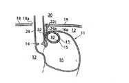
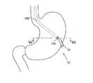
これらの目的および他の目的は、添付の特許請求の範囲において説明されている装置によって達成される。したがって、生体適合性材料を含む外面を有する埋め込み可能な移動制限デバイスを含む胃酸逆流性疾患の治療用の装置を提供し、その際に、患者の横隔膜と胃底壁との間のある位置で、外面の少なくとも一部が患者の胃底壁に当たる形で置かれるように移動制限デバイスを構成し、患者の横隔膜に向かう患者の胃の噴門切痕の移動が制限されるようにすることによって、逆流性疾患を治療するための装置が得られる。移動制限デバイスは、少なくとも125mm3サイズ、および少なくとも15mmの外周長を有し、患者の胃の噴門切痕が患者の横隔膜に向かって移動するのを制限し、それにより、噴門が滑脱(スライド)して患者の横隔膜開口部を通り患者の胸腔内に入るのを防ぎ、患者の噴門括約筋に対する患者の腹部から加えられる支持圧力を維持する。固定デバイスは、移動制限デバイスを前記位置に固定するように構成される。These and other objects are achieved by the device described in the appended claims. Accordingly, there is provided an apparatus for the treatment of gastric acid reflux disease, comprising an implantable movement restriction device having an outer surface comprising a biocompatible material, wherein at some point between the patient's diaphragm and the fundus wall. By configuring the movement restriction device such that at least a portion of the outer surface is placed against the patient's fundus wall, such that movement of the patient's stomach cardia notch toward the patient's diaphragm is restricted. An apparatus for treating reflux disease is provided. Movement restriction device comprises at least 125 mm3 size, and at least 15mm outer peripheral length of a cardiac notch of the patient's stomach to restrict the movement towards the diaphragm of the patient, thereby cardia is slipped (slide) To prevent entry through the patient's diaphragm opening into the patient's thoracic cavity and maintain the supporting pressure applied from the patient's abdomen to the patient's cardia sphincter. The fixation device is configured to fix the movement restriction device in the position.
胃底は食道に比べて傷つきやすいため、埋め込まれた移動制限デバイスの外面を胃底壁に当接するように構成することによって、組織への損傷の移動などの合併症のリスクを最小限度に抑えられる。 Because the fundus is more vulnerable than the esophagus, configuring the implanted mobility-restricting device against the fundus wall minimizes the risk of complications, such as transferring damage to tissue. Can be
本発明の第1の実施形態では、固定デバイスは、移動制限デバイスを前記位置に固定するために移動制限デバイスを取り囲む胃底壁の部分をつなぎ合わせる縫合糸またはステープラ(ホチキス針)を含む。つまり、移動制限デバイスは、少なくとも部分的には、陥入空間内に留置される。したがって、埋め込み可能な移動制限デバイスをこの方法で間接的に固定することによって、移動制限デバイスと組織との間の縫合は不要になり、延いては、合併症のリスクもさらに低減する。移動制限デバイスをこの方法で適所に保持する結果、長期間特性が改善された弾性支持が得られた。 In a first embodiment of the present invention, the fixation device includes a suture or stapler that ties the portion of the fundus wall surrounding the movement restriction device to secure the movement restriction device in said position. That is, the movement restriction device is at least partially retained within the invaginated space. Thus, indirectly securing the implantable movement restriction device in this manner eliminates the need for suturing between the movement restriction device and the tissue, thus further reducing the risk of complications. Holding the movement restriction device in place in this manner resulted in a resilient support with improved properties over time.
縫合糸またはステープラなどの固定デバイスは、移動制限デバイスを患者の胃壁の内側または外側から実質的にまたは完全に陥入するように胃底壁の部分をつなぎ合わせることができる。移動制限デバイスが、患者の胃壁の外側に留置される場合、移動制限デバイスは、移動制限デバイスの体積を実質的に超える体積だけ、胃腔が実質的に減少するように胃底壁によって陥入される。 An anchoring device, such as a suture or stapler, can join portions of the fundus wall such that the movement restriction device is substantially or completely invaginated from the inside or outside of the patient's stomach wall. If the movement restriction device is placed outside the patient's stomach wall, the movement restriction device is invaginated by the fundus wall such that the gastric cavity is substantially reduced by a volume substantially greater than the volume of the movement restriction device. Is done.
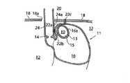
本発明の第2の実施形態では、固定デバイスは、前記位置にある移動制限デバイスを胃底壁に取り付ける埋め込み可能な第1の固定デバイス、間接的にまたは直接的に、移動制限デバイスを患者のHis角の近くで食道に固定する第2の固定デバイス、および間接的にまたは直接的に、移動制限デバイスを患者の横隔膜筋肉または関連する筋肉に固定する第3の固定デバイスを含む。第1、第2、および第3の固定デバイスのうちのいずれも、複数の縫合糸またはステープラで構成されうる。第1の固定デバイスは、移動制限デバイスを胃壁に長期間取り付けておくための組織成長促進構造を備えることができる。組織成長促進構造は、比較的広い接触表面が胃に向くようにして胃壁に縫合することができる。ネットなどの構造の比較的広い表面があれば、長期間にわたって移動制限デバイスを適所に保持するためにヒト組織の成長侵入を行わせることができる。組織成長促進構造は、ネット状構造を胃底壁に取り付ける縫合糸またはステープラを含むことができる。 In a second embodiment of the present invention, the fixation device is an implantable first fixation device that attaches the movement restriction device in said position to the fundic wall, indirectly or directly, the movement restriction device of the patient. A second fixation device that secures to the esophagus near the His angle and a third fixation device that indirectly or directly secures the movement restriction device to the diaphragm muscle or related muscles of the patient. Any of the first, second, and third fixation devices may be comprised of a plurality of sutures or staplers. The first fixation device can include a tissue growth promoting structure for keeping the movement restriction device on the stomach wall for an extended period of time. The tissue growth promoting structure can be sutured to the stomach wall with a relatively large contact surface facing the stomach. The relatively large surface of the structure, such as a net, can allow for growth invasion of human tissue to hold the movement restriction device in place for extended periods of time. The tissue growth promoting structure can include a suture or stapler that attaches the net-like structure to the fundus wall.
本発明の第1の実施形態に従って移動制限デバイスを陥入することに加えて、第2の固定デバイスは、間接的にまたは直接的に、移動制限デバイスを患者のHis角に近い食道に固定するために使用することができ、また第3の固定デバイスは、間接的にまたは直接的に、移動制限デバイスを患者の横隔膜筋肉または関連する筋肉に固定するために使用することができる。 In addition to invading the movement restriction device according to the first embodiment of the present invention, the second fixation device indirectly or directly secures the movement restriction device to the esophagus near the His angle of the patient. And the third fixation device can be used to indirectly or directly fix the movement restriction device to the diaphragm muscle or related muscles of the patient.
移動制限デバイスの少なくとも一部は、胃酸によって破壊可能である、または破壊可能でない材料から作ることができる。 At least a portion of the movement restriction device can be made from a material that is or is not breakable by gastric acid.
移動制限デバイスは、ゲルまたは流体で膨張可能であり、また膨張するように構成されうる。移動制限デバイスを膨張させるために流体を収容するための流体またはゲル収容部材を備えることができる。 The movement restriction device is expandable with a gel or fluid and may be configured to expand. A fluid or gel containing member for containing a fluid to inflate the movement restriction device can be provided.
移動制限デバイスは、均質材料を含むことができ、また固形体とすることもできる。 The movement restriction device can include a homogeneous material and can be solid.
移動制限デバイスは、室を画定する囲い壁を備えることができる。 The movement restriction device can include an enclosure that defines the room.
移動制限デバイスは、剛性のある、弾性的な、または柔軟な外壁を有することができる。外壁が剛体である場合、胃運動によって生じる力を受けても変形しない状態を保持する十分な剛性を有する。上述の第1の実施形態により、移動制限デバイスが陥入される場合、移動制限デバイスは、好ましくは、患者の胃底壁によって少なくとも部分的に陥入されるように構成され、生体適合性材料を含む外面を有する本体を備える。本体の外面の実質的部分は、患者の横隔膜と陥入胃底壁の下部の部分との間で前記位置において胃壁に当接するように構成される。適宜、本体は、ショア硬度25または15より柔らかい材料で作られる。 The movement restriction device can have a rigid, elastic, or flexible outer wall. When the outer wall is rigid, the outer wall has sufficient rigidity to maintain a state in which the outer wall is not deformed even under the force generated by the stomach movement. According to the first embodiment described above, when the movement restriction device is invaginated, the movement restriction device is preferably configured to be at least partially invaginated by the patient's fundus wall, and the biocompatible material A body having an outer surface that includes: A substantial portion of the outer surface of the body is configured to abut the stomach wall at said location between the patient's diaphragm and the lower portion of the invaginated fundus wall. Optionally, the body is made of a material softer than a Shore hardness of 25 or 15.
本体の第1の全体的設計によれば、本体は、本体を通る軸に垂直な平面内で見たときに最大の外周長を持つ。前記軸に垂直な他の平面内で見たときの本体の外周長は、最大外周長に等しいか、または最大外周長からの方向で前記軸にそって見たときに減少する。例えば、本体は、実質的に卵形、球形、意図された中央部を持つ実質的に卵に似た形状、または曲がった卵に似た形状とすることができる。 According to a first general design of the body, the body has a maximum perimeter when viewed in a plane perpendicular to the axis through the body. The perimeter of the body when viewed in another plane perpendicular to the axis is equal to or less than the maximum perimeter when viewed along the axis in a direction from the maximum perimeter. For example, the body can be substantially ovoid, spherical, substantially egg-shaped with an intended central portion, or curved egg-like.
本体の第2の全体的設計によれば、本体を通る軸に垂直な平面内で見たときの本体の外周長は、平面が前記軸にそってずれたときに少なくとも2倍に増大し減少するか、または平面が前記軸にそってずれたときに少なくとも1倍に減少し増大する。例えば、本体は、実質的に腎臓に似た形状であってもよい。 According to a second general design of the body, the perimeter of the body when viewed in a plane perpendicular to the axis passing through the body increases and decreases by at least a factor of two when the plane is displaced along said axis. Or decreases and increases at least one-fold when the plane is displaced along said axis. For example, the body may be substantially shaped like a kidney.
好ましくは、本体は、胃からの腸出口より大きなサイズで寸法が決められる。本体は、30または40mm以上の最小外径を有することができ、また150、110、90、70、50、または30mmの最小外周長を有することができる。 Preferably, the body is sized and sized larger than the intestinal outlet from the stomach. The body can have a minimum outer diameter of 30 or 40 mm or more, and can have a minimum circumference of 150, 110, 90, 70, 50, or 30 mm.
適宜、本体は、患者の胃壁を傷つけてしまう鋭すぎる縁のない丸い輪郭を有し、また胃底壁に寄りかかるための概して滑らかな外面を有する。 Optionally, the body has a rounded profile without edges that are too sharp to damage the patient's stomach wall and has a generally smooth outer surface to lean against the fundus wall.
本体は、患者の胃の内側または外側に埋め込み可能であり、外科手術によって患者の胃壁に取り付けられるように構成される。本体は、腹腔鏡検査に使用するためのトロカールの直径と比べて小さい直径を有する細身の形態を取るように変更可能であり、これにより、本体は、前記細身の形態に変えたときに、トロカールに押し通すか、または引き通すことができる。本体は、ゲルなどの流体を充填される室を画定する柔軟な外壁を備えることができ、これにより、本体をそのようなトロカールに通すことができる。あるいは、本体は、弾性圧縮性材料で構成することができ、これにより、本体をトロカールに通すことができる。 The body is implantable inside or outside the patient's stomach and is configured to be surgically attached to the patient's stomach wall. The body can be modified to take the form of a slender body having a smaller diameter compared to the diameter of the trocar for use in laparoscopy, such that the body, when changed to said slender form, is trocar-like. Can be pushed through or pulled through. The body can have a flexible outer wall defining a chamber filled with a fluid such as a gel, which allows the body to pass through such a trocar. Alternatively, the body can be comprised of an elastically compressible material, which allows the body to pass through a trocar.
本体は、中空であってもよく、このような中空の本体内に挿入され得るように、且つつなぎ合わせて本体の内側で1つの一体ピースを形成するようにされた少なくとも2つの個別ピースを備えることができ、これにより、腹腔鏡検査に使用するため本体をトロカールに通すことができる。あるいは、本体は、患者の体内に挿入した後に流体またはゲルで充填するための、外壁および中空圧縮内部を備えることができる。 The body may be hollow and comprise at least two individual pieces adapted to be inserted into such a hollow body and joined together to form one integral piece inside the body. The body can be passed through the trocar for use in laparoscopic examination. Alternatively, the body can include an outer wall and a hollow compression interior for filling with a fluid or gel after insertion into a patient.
本体は、注入口を持つ室を備えることができ、本体の室は、その注入口を通して流体を充填される。 The body can include a chamber having an inlet, and the chamber of the body is filled with fluid through the inlet.
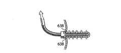
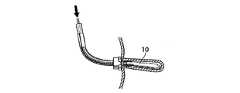
本体は、腹腔鏡検査用にトロカールに本体を押し通すか、または引き通すために使用されるように構成された少なくとも1つの保持デバイスを備えることができる。保持デバイスは、手術器具によって保持されるように構成された本体の延長部を保持するように構成されている。より具体的には、保持デバイスは、保持デバイスに通して挿入された糸またはバンドを保持するように構成される。本体が外壁を備える場合、保持デバイスは、少なくとも部分的には本体の外壁の内側に留置される。 The body can include at least one retention device configured to be used to push or pull the body through a trocar for laparoscopy. The retaining device is configured to retain an extension of the body configured to be retained by the surgical instrument. More specifically, the holding device is configured to hold a thread or band inserted through the holding device. If the body comprises an outer wall, the retaining device is at least partially deployed inside the outer wall of the body.
有利な一実施形態では、本体は、サイズが調節可能であり、患者の胃底壁内に陥入される。その結果、本体は、そのサイズが大きくなったときに患者の胃底壁を引き伸ばし、これにより、肥満を患っている患者も満腹させる。患者の胃壁の異なる部分を引き伸ばすために少なくとも2つの埋め込み可能な調節可能引き伸ばしデバイスを備え、これにより、患者の食欲に効率的に影響を及ぼすことによって肥満を治療することができる。2つの引き伸ばしデバイスは、患者の体外から適切に調節され、これにより、第1の引き伸ばしデバイスは、患者の胃壁の第1の部分を引き伸ばすように初回に調節され、第2の引き伸ばしデバイスは、患者の胃壁の第2の部分を引き伸ばすように2回目に調節される。 In an advantageous embodiment, the body is adjustable in size and is invaginated into the patient's fundus wall. As a result, the body stretches the patient's fundus wall as it increases in size, thereby filling the patient suffering from obesity. It comprises at least two implantable adjustable stretching devices for stretching different parts of the patient's stomach wall, which can treat obesity by efficiently affecting the patient's appetite. The two stretching devices are properly adjusted from outside the patient, whereby the first stretching device is initially adjusted to stretch a first portion of the patient's stomach wall, and the second stretching device is adjusted to the patient. A second time to stretch the second portion of the stomach wall.
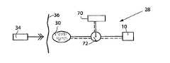
引き伸ばしデバイスは、液圧で調節することもできる。この場合、液圧式調節引き伸ばしデバイスに接続された皮下埋め込み可能液圧タンクを備え、これにより、液圧式調節引き伸ばしデバイスは、液圧タンクを手で圧すことによって非侵襲的に調節される。さらに、移動制限デバイスは、適宜、膨張可能な本体を備え、ポンプおよび本体と流体接触している室が備えられ、ポンプは、本体から室へ流体または空気を送り込むことによって液圧タンクを調節する。 The stretching device can also be adjusted hydraulically. In this case, there is a subcutaneously implantable hydraulic tank connected to the hydraulic adjusting and stretching device, whereby the hydraulic adjusting and stretching device is adjusted non-invasively by manually pressing the hydraulic tank. Further, the movement restriction device optionally includes an inflatable body, and is provided with a pump and a chamber in fluid contact with the body, the pump adjusting the hydraulic tank by pumping fluid or air from the body into the chamber. .
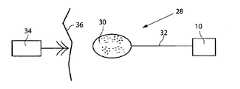
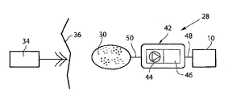
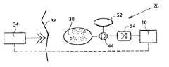
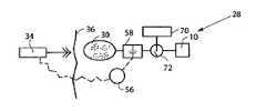
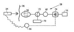
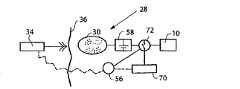
装置は、刺激パルスを噴門筋に送出して噴門筋を刺激し、これにより噴門をさらに閉じて逆流疾病を付加的に予防する埋め込み可能刺激デバイスを備えることができる。刺激デバイスは、少なくとも1つの導体と、刺激パルスを受け取り、それらを噴門筋に印加し、それによって噴門筋を刺激する少なくとも1つの電極とで構成される。少なくとも1つの電極は、胃食道縫合または胃壁内の陥入によって適所に保持することもできる。刺激パルスは、パルス列として送出することができ、このパルス列は、間にタイムブレイクを入れて繰り返され、ブレイクはパルス列内のそれぞれのパルスの間のブレイクを延ばす。刺激デバイスは、電子回路およびエネルギー源、好ましくはそれらを一体的に組み込んだ構成としたものを備えることができる。一実施形態では、刺激デバイスによる噴門の刺激は、括約筋緊張を高めて噴門を完全に閉じるためにエネルギー・パルスを使用して行われ、刺激デバイスを制御するための制御デバイスは、刺激デバイスを動作させるために患者によって操作可能であり、その動作状態において、刺激デバイスは、噴門括約筋が前記エネルギー・パルスで刺激される運転モードと噴門が刺激されない静止モードとの間で患者が嚥下しないときに連続的に交互動作する。 The apparatus can include an implantable stimulation device that delivers a stimulation pulse to the cardiac muscle to stimulate the cardiac muscle, thereby further closing the cardia and additionally preventing reflux disease. The stimulation device is comprised of at least one conductor and at least one electrode that receives stimulation pulses and applies them to the cardiac muscle, thereby stimulating the cardiac muscle. The at least one electrode may also be held in place by a gastroesophageal suture or invagination in the stomach wall. The stimulation pulses can be delivered as a pulse train, which is repeated with a time break in between, the breaks extending the break between each pulse in the pulse train. The stimulation device may include an electronic circuit and an energy source, preferably one that incorporates them. In one embodiment, stimulation of the cardia by the stimulation device is performed using an energy pulse to increase sphincter tone and completely close the cardia, and the control device for controlling the stimulation device operates the stimulation device. Operable by the patient to cause the stimulation device to operate continuously when the patient does not swallow between a driving mode in which the cardinal sphincter is stimulated with the energy pulse and a stationary mode in which the cardia is not stimulated. Work alternately.
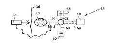
刺激デバイスは、好ましくは、患者の身体パラメータまたは移動制限デバイスの機能パラメータを感知するための少なくとも1つのセンサ、および刺激デバイスを制御するための内部制御ユニットを備える。 The stimulation device preferably comprises at least one sensor for sensing a physical parameter of the patient or a functional parameter of the movement restriction device, and an internal control unit for controlling the stimulation device.
通常は、内部制御ユニットは、センサからの情報に応答して刺激デバイスを制御する。 Typically, an internal control unit controls the stimulation device in response to information from the sensors.
食道の収縮波、または食物摂取に相関する任意の他のパラメータを感知するセンサは、情報を内部制御ユニットに送信し、次いで、内部制御ユニットは、センサからのそのような情報に応答して刺激を停止する。 A sensor that senses the esophageal contraction wave, or any other parameter that correlates with food intake, sends information to an internal control unit, which then stimulates in response to such information from the sensor. To stop.
刺激デバイスは、いつでも、患者によって制御することができる。 The stimulation device can be controlled by the patient at any time.
本発明は、逆流疾病を治療する腹部外科治療法にさらに関する。 The present invention further relates to abdominal surgery for treating reflux disease.
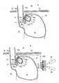
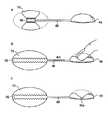
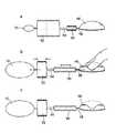
第1の方法によれば、患者の逆流疾病は、患者に埋め込まれたときに、横隔膜筋肉に関する胃切痕の移動を制限し、噴門が上に滑脱して横隔膜裂孔開口部を通るのを防ぐ移動制限デバイスを埋め込むことによって治療される。この方法は、針またはチューブ状器具を患者の身体の腹部に挿入するステップと、針またはチューブ状器具を使用して患者の腹部にガスを充填するステップと、少なくとも2つの腹腔鏡検査トロカールを患者の体内に留置するステップと、カメラを腹腔鏡検査トロカールの1つに通して患者の腹部に挿入し、少なくとも1つの切開具を前記少なくとも2つの腹腔鏡検査トロカールのうちの1つに通して挿入するステップと、胃の一領域を切開するステップと、デバイスを腹腔内に導入するステップと、デバイスを胃底壁の外側に置くステップと、デバイス用に胃底壁内に袋を形成するステップと、胃底壁に縫合糸またはステープラを施すことによってデバイスをこの袋内に陥入し、これにより、噴門が滑脱して患者の横隔膜開口部を通り患者の胸腔内に入るのを防ぎ、患者の噴門括約筋を支持する患者の腹部からの圧力支持を維持するステップとを含む。 According to the first method, the reflux disease of the patient, when implanted in the patient, limits the movement of the gastric notch with respect to the diaphragm muscle and prevents the cardia from slipping up and past the diaphragm hiatus opening Treated by implanting a movement restriction device. The method includes inserting a needle or tubular device into the abdomen of the patient's body, filling the abdomen of the patient with the gas using the needle or tubular device, and providing at least two laparoscopic trocars to the patient. Placing the camera through one of the laparoscopic trocars and into the patient's abdomen, and inserting at least one dissecting instrument through one of the at least two laparoscopic trocars Incising an area of the stomach, introducing the device into the abdominal cavity, placing the device outside the fundus wall, and forming a bag in the fundus wall for the device. The device is recessed into the bag by applying sutures or staplers to the fundus wall, which causes the cardia to slip and pass through the patient's diaphragm opening. Prevented from entering into the thoracic cavity, and a step of maintaining the pressure support from the abdomen of the patient to support the cardiac sphincter of the patient.
第1の方法と同じ目的のために逆流疾病を治療する第2の腹部治療法では、初期ステップを使用し、これは、胃底壁内に穴を形成することと、移動制限デバイスを腹腔内に導入することと、デバイスを穴に通し、胃内に導入することと、デバイスを胃底壁の内側に置くことと、胃底壁の内側に留置されているデバイス用に胃腔の外側に袋を形成することと、胃底壁に縫合糸またはステープラを施すことによってデバイスをこの袋内に陥入し、噴門が滑脱して患者の横隔膜開口部を通り患者の胸腔内に入るのを防ぎ、患者の噴門括約筋を支持する患者の腹部からの支持圧力を維持することとを含む。 A second abdominal treatment method for treating reflux disease for the same purpose as the first method uses an initial step, which involves forming a hole in the fundus wall and adding a movement restriction device to the intraperitoneal cavity. Introducing the device through the hole and into the stomach; placing the device inside the fundus wall; and outside the gastric cavity for the device placed inside the fundus wall. Forming the bag and applying sutures or staplers to the fundus wall invades the device into the bag, preventing the cardia from slipping through the patient's diaphragm opening and into the patient's thoracic cavity And maintaining support pressure from the patient's abdomen supporting the patient's cardiac sphincter.
患者の逆流疾病を治療する第3の腹部治療法は、すでに開示されている方法と同じ目的のために移動制限デバイスを埋め込むことを含み、また患者の腹壁を外科的に切開して開口部を形成するステップと、患者の胃の一領域を切開するステップと、移動制限デバイスを腹腔切開部に通して導入するステップと、胃底壁にデバイスを取り付け、これにより、噴門が滑脱して患者の横隔膜開口部を通り患者の胸腔内に入るのを防ぎ、患者の噴門括約筋を支持する患者の腹部からの支持圧力を維持するステップとを含む。第1の代替形態によれば、この方法は、デバイスを胃底壁の外側に置くことと、デバイス用に胃底壁内に袋を形成することと、胃底壁に縫合糸またはステープラを施すことによってデバイスをこの袋内に陥入し、これにより、噴門が滑脱して患者の横隔膜開口部を通り患者の胸腔内に入るのを防ぎ、患者の噴門括約筋を支持する患者の腹部からの支持圧力を維持することとを含む。第2の代替形態によれば、この方法は、胃底壁内に穴を形成することと、移動制限デバイスを穴に通し、胃内に導入することと、デバイスを胃底壁の内側に置くことと、デバイス用に胃底壁に袋を形成することと、胃底壁に縫合糸またはステープラを施すことによってデバイスをこの袋内に陥入し、噴門が滑脱して患者の横隔膜開口部を通り患者の胸腔内に入るのを防ぎ、患者の噴門括約筋を支持する患者の腹部からの支持圧力を維持することとを含む。 A third abdominal treatment for treating a patient's reflux disease involves implanting a movement restriction device for the same purpose as previously disclosed, and also surgically incising the patient's abdominal wall to form an opening. Forming, incising an area of the patient's stomach, introducing the movement restriction device through the abdominal incision, and attaching the device to the fundus wall, whereby the cardia slides out of the patient, Preventing entry into the patient's thoracic cavity through the diaphragm opening and maintaining supporting pressure from the patient's abdomen supporting the patient's cardia sphincter. According to a first alternative, the method includes placing the device outside the fundus wall, forming a bag in the fundus wall for the device, and applying a suture or stapler to the fundus wall. The device into the bag, thereby preventing the cardia from slipping and passing through the patient's diaphragm opening into the patient's thoracic cavity and providing support from the patient's abdomen to support the patient's cardinal sphincter Maintaining pressure. According to a second alternative, the method comprises forming a hole in the fundus wall, passing the movement restriction device through the hole and introducing into the stomach, and placing the device inside the fundus wall Forming a bag in the fundus wall for the device and applying a suture or stapler to the fundus wall to inset the device into the bag, and the cardia slips off to open the patient's diaphragm opening. And maintaining support pressure from the patient's abdomen supporting the patient's cardiac sphincter.
この方法は、縫合糸またはステープラを施すことによってデバイスを胃底壁に固定すること、および/または縫合糸またはステープラを施すことによって胃底壁を患者の食道の下部に固定すること、および/または胃底壁を患者の横隔膜筋または関連する筋肉に固定することをさらに含む。この方法は、患者の体外から逆流治療デバイスを調節するための装置を備えることと、前記装置を動作させて逆流治療デバイスを調節することとをさらに含むことができる。逆流治療デバイスの調節は、埋め込まれたときに充填体の体積を変えることを含むことができる。この目的のために、これらの方法は、埋め込まれた充填体内に注入するための流体を入れた噴射型注射器を備えることと、一定体積の流体を充填体に注入することとを含むことができる。好ましくは、これらの方法は、デバイスを袋に封入することを含む。一実施形態では、この方法では、袋を少なくとも部分的に開いておき、これにより、袋が開口部を1つだけ示すか、袋が2つの開口部を示し、胃の周りに非円周的に延在するようにできる。一般的に、袋の容積は15ミリリットル超であることが好ましい。 The method includes securing the device to the fundus wall by applying a suture or stapler, and / or securing the fundus wall to the lower portion of the patient's esophagus by applying a suture or stapler, and / or The method further includes securing the fundus wall to the patient's diaphragm muscle or related muscles. The method can further include providing an apparatus for adjusting the reflux treatment device from outside the patient, and operating the apparatus to adjust the reflux treatment device. Adjusting the reflux treatment device can include changing the volume of the fill when implanted. To this end, these methods can include providing an injection syringe with fluid for infusion into the implanted fill, and injecting a volume of fluid into the fill. . Preferably, these methods include encapsulating the device in a bag. In one embodiment, the method leaves the bag at least partially open, such that the bag shows only one opening or the bag shows two openings and a non-circumferential around the stomach. Can be extended. Generally, it is preferred that the volume of the bag be greater than 15 milliliters.
逆流疾病を治療する他の腹腔鏡検査腹部治療法は、針またはチューブ状器具を患者の身体の腹部に挿入することと、針またはチューブ状器具を使用して患者の腹部にガスを充填することと、少なくとも2つの腹腔鏡検査トロカールを患者の体内に留置することと、カメラを腹腔鏡検査トロカールの1つに通して患者の腹部に挿入することと、少なくとも1つの切開具を前記少なくとも2つの腹腔鏡検査トロカールのうちの1つに通して挿入することと、胃の一領域を切開することと、デバイス用に胃底壁から袋を形成することと、縫合糸およびステープラを施すことによって袋を閉じることと、注入可能充填材料を含む注入部材を導入することと、充填材料を袋の中に注入し、これにより、患者が立位にあるときに患者の噴門の近く、および上にある患者の腹部内の容積を充填する充填体を形成し、噴門が滑脱して患者の横隔膜開口部を通り患者の胸腔内に入るのを防ぎ、患者の噴門括約筋を支持する患者の腹部内の圧力を維持することとを含む。 Other laparoscopic abdominal treatments to treat reflux disease include inserting a needle or tubular device into the abdomen of the patient's body and using the needle or tubular device to fill the patient's abdomen with gas. Placing at least two laparoscopic trocars in a patient's body, inserting a camera through one of the laparoscopic trocars into the patient's abdomen, and attaching at least one dissector to the at least two trocars. Bag by inserting through one of the laparoscopic trocars, incising an area of the stomach, forming a bag from the fundus wall for the device, and applying sutures and stapler Closing and introducing an injection member containing an injectable filling material, and injecting the filling material into the bag, thereby near the patient's cardia when the patient is in the upright position, and In the patient's abdomen to form a filling that fills the volume in the patient's abdomen, prevent the cardia from slipping through the patient's diaphragm opening and into the patient's thoracic cavity, and support the patient's cardia sphincter And maintaining the pressure.
逆流疾病を治療する他の外科腹部治療法は、患者の腹部内に入るように皮膚を切って開口部を形成し胃の一領域を切開することと、デバイス用に胃底壁から袋を形成することと、縫合糸およびステープラを施すことによって袋を閉じることと、注入可能充填材料を含む注入部材を導入することと、充填材料を袋の中に注入し、これにより、患者が立位にあるときに患者の噴門の近く、および上にある患者の腹部内の容積を充填する充填体を形成し、噴門が滑脱して患者の横隔膜開口部を通り患者の胸腔内に入るのを防ぎ、患者の噴門括約筋を支持する患者の腹部内の圧力を維持することとを含む。 Other surgical abdominal treatments for treating reflux disease include cutting the skin into the patient's abdomen to form an opening and incising an area of the stomach and forming a bag from the fundus wall for the device Closing the bag by applying sutures and staplers, introducing an injection member containing an injectable filler material, and injecting the filler material into the bag, thereby allowing the patient to stand upright. Forming a filling that fills the volume in the patient's abdomen near and above the patient's cardia at one time, preventing the cardia from slipping through the patient's diaphragm opening and into the patient's chest cavity; Maintaining pressure within the patient's abdomen that supports the patient's cardiac sphincter.
説明されている他の方法は、胃底壁の外側に袋を形成し、充填体が胃底壁の内側に当たるように留置することを含むことができるか、あるいは、これらの方法は、胃底壁内に穴を形成することを含み、袋は、胃底壁の内側に形成され、充填体が胃底壁の外側に当たるように留置される。説明されている他の方法は、好ましくは、縫合糸またはステープラを施すことによって胃底壁を患者の食道の下部に固定すること、および/または胃底壁を患者の横隔膜筋または関連する筋肉に固定することも含む。また、一般的に、袋の容積は15ミリリットル超であることが好ましい。充填材料は、好ましくは、流体材料から半固体または固体材料への硬化プロセスを受けることができる。このような硬化プロセスは、好ましくは、周囲温度から体温までの温度上昇によって誘発される。当業者によく知られている、好適なこのような材料は、(架橋剤および触媒の存在下で)熱の影響の下で架橋反応を受けうる熱硬化性ポリシロキサンである。 Other methods that have been described can include forming a bag outside the fundus wall and placing the fill so that it hits the inside of the fundus wall, or these methods can Including forming a hole in the wall, the bag is formed on the inside of the fundus wall and is placed so that the filling is on the outside of the fundus wall. Other methods described include securing the fundus wall to the patient's lower esophagus, preferably by applying sutures or staplers, and / or attaching the fundus wall to the patient's diaphragm muscle or related muscles. Including fixing. Also, it is generally preferred that the volume of the bag be greater than 15 milliliters. The filler material can preferably undergo a curing process from a fluid material to a semi-solid or solid material. Such a curing process is preferably triggered by an increase in temperature from ambient to body temperature. Suitable such materials, well known to those skilled in the art, are thermoset polysiloxanes that can undergo a crosslinking reaction under the influence of heat (in the presence of a crosslinking agent and a catalyst).
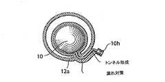
患者に埋め込まれたときに、横隔膜筋肉に関する胃切痕の移動を制限し、噴門が上に滑脱して横隔膜裂孔開口部を通るのを防ぐ移動制限デバイスを埋め込むことによって患者の逆流疾病を治療するさらに他の腹腔鏡検査腹部治療法は、針またはチューブ状器具を患者の身体の腹部に挿入するステップと、針またはチューブ状器具を使用して患者の腹部にガスを充填するステップと、少なくとも2つの腹腔鏡検査トロカールを患者の体内に留置するステップと、カメラを腹腔鏡検査トロカールの1つに通して患者の腹部に挿入するステップと、少なくとも1つの切開具を前記少なくとも2つの腹腔鏡検査トロカールのうちの1つに通して挿入するステップと、胃の一領域を切開するステップと、胃底壁内に穴を形成するステップと、移動制限デバイスを腹腔内に導入するステップと、デバイスを穴に通し、胃内に導入するステップと、デバイスを胃底壁の外側に置くステップと、胃底壁の外側に留置されるデバイスを固定するステップと、噴門が滑脱して患者の横隔膜開口部を通り患者の胸腔内に入るのを防ぎ、患者の噴門括約筋を支持する患者の腹部からの支持圧力を維持するステップとを含む。この方法は、縫合糸またはステープラを施すことによってデバイスを胃底壁に固定するステップをさらに含むことができる。 Treat the patient's reflux disease by implanting a movement-restricting device that, when implanted in the patient, restricts the movement of the gastric notch with respect to the diaphragm muscles and prevents the cardia from sliding up and through the diaphragm hiatus opening Still other laparoscopic abdominal treatments include inserting a needle or tubular device into the abdomen of the patient's body, filling the abdomen of the patient with the needle or tubular device using at least two steps. Placing two laparoscopic trocars in a patient's body, inserting a camera through one of the laparoscopic trocars into the patient's abdomen, and inserting at least one dissector into said at least two laparoscopic trocars Inserting through one of the stomach, incising an area of the stomach, forming a hole in the fundus wall, and restricting movement. Introducing the chair into the abdominal cavity, passing the device through the hole and into the stomach, placing the device outside the fundus wall, and securing the device to be placed outside the fundus wall Preventing the cardia from slipping through the patient's diaphragm opening and into the patient's thoracic cavity, and maintaining supporting pressure from the patient's abdomen supporting the patient's cardinal sphincter. The method can further include securing the device to the fundus wall by applying a suture or stapler.
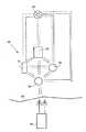
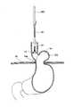
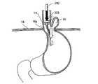
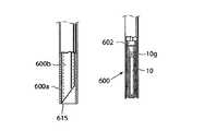
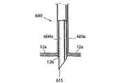
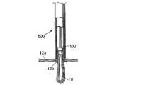
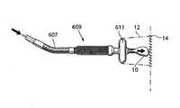
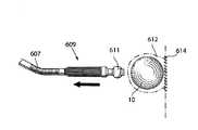
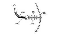
本発明は、前述の腹腔鏡検査法のいずれかとともに使用するのに適している、逆流疾病を治療するためにヒト患者の胃底壁内に陥入すべき移動制限デバイスを備えるための腹腔鏡器具にも関係する。この腹腔鏡器具は、全体的に、腹腔鏡下手術時に患者の腹部内に導入される腹腔鏡検査トロカールの直径に比べて小さい直径を有する、近位端および遠位端を有する細長い部材と、胃底壁を押すための押しデバイスであって、胃底壁の、胃腔内へと突き出るチューブ形状部分を形成するためのものであり、且つそのチューブ形状部分内に陥入されるべき移動制限デバイスを含んでいる、押しデバイスとを備える。この胃押しデバイスには、それと一緒になって腹腔鏡器具が胃底壁のチューブ形状部分を形成するのを補助するために胃底を吸引する真空吸引デバイスをも備える。真空吸引デバイスは、腹腔鏡器具の近位端から遠位端に至り、腹腔鏡器具の端部のところにある真空通路を備え、その端部には押しデバイスがある。真空通路は、押しデバイスに付着するように胃壁部分を吸引しチューブ状胃壁部分をさらに形成するように構成された複数の小さな開口部に分けられる。腹腔鏡器具は、移動制限デバイスをチューブ状形状胃部分内に導入するように構成された挿入デバイスをさらに備える。腹腔鏡器具は、前記開口部内での胃間クランプによって、実質的に閉じられているチューブ状部分の開口部を保持するための少なくとも1つの締め付けデバイスをさらに備えることができ、この腹腔鏡器具は、開口部を後から縫合できるような形で少なくとも1つの締め付けデバイスを開口部のところに配置するように構成される。腹腔鏡器具は、縫合の前または後に移動制限デバイスを膨張させるための膨張デバイスをさらに備えることができる。腹腔鏡器具は、移動制限デバイスを取り囲む少なくとも部分的に閉じられた空間を形成するために胃間縫合糸でチューブ状部分の開口部を縫合するように構成された縫合デバイスをさらに備えることができ、この腹腔鏡器具は、胃底壁内に少なくとも部分的に陥入された移動制限デバイスを残して撤去されるように構成される。縫合デバイスは、その遠位端のところで胃内に配置される細長い部材上に設けられた第1および第2の縫合糸位置決め部材を備えることができる。腹腔鏡器具は、胃壁がカップ状部分の開放端の両側にある状態で第1および第2の縫合糸位置決め部材が互いの前にある位置において第1および第2の縫合部材を調整するように構成され、また一列の胃間縫合糸で胃底壁のカップ状部分の開放端を縫合するように構成された操作デバイスをさらに備える。縫合デバイスは、好ましくは、患者の身体の外側から縫合糸を再装填可能であり、前記一列の胃間縫合糸で胃底壁のカップ状部分の開放端を縫合するように構成されている、操作可能再装填可能多重縫合デバイスを備え、この一列の縫合糸は同時に縫合される2つまたはそれ以上の縫合糸またはステープラを含む。縫合デバイスは、2つまたはそれ以上の縫合糸を同時に縫合するために複数の縫合糸を備えることもできる。 The present invention relates to a laparoscope for providing a movement restriction device that is suitable for use with any of the foregoing laparoscopic methods to move into the fundus wall of a human patient to treat reflux disease. It also relates to equipment. The laparoscopic instrument generally includes an elongated member having a proximal end and a distal end having a diameter smaller than a diameter of a laparoscopic trocar introduced into the patient's abdomen during laparoscopic surgery; A push device for pushing the fundus wall, for forming a tube-shaped portion of the fundus wall protruding into the gastric cavity, and a movement restriction to be invaded into the tube-shaped portion And a push device including the device. The gastric pushing device also includes a vacuum suction device with which the fundus is aspirated to assist the laparoscopic instrument in forming a tube-shaped portion of the fundus wall. The vacuum suction device includes a vacuum passage from the proximal end to the distal end of the laparoscopic instrument at the end of the laparoscopic instrument, at which end there is a pushing device. The vacuum passage is divided into a plurality of small openings configured to aspirate the gastric wall portion to adhere to the pushing device and further form a tubular gastric wall portion. The laparoscopic instrument further comprises an insertion device configured to introduce the movement restriction device into the tubular shaped gastric portion. The laparoscopic instrument may further comprise at least one clamping device for retaining the opening of the substantially closed tubular portion by an intergastric clamp in the opening, the laparoscopic instrument comprising: Is configured to place at least one fastening device at the opening such that the opening can be sutured later. The laparoscopic instrument can further comprise an inflation device for inflating the movement restriction device before or after suturing. The laparoscopic instrument can further comprise a suturing device configured to suture the opening of the tubular portion with an intergastric suture to form an at least partially enclosed space surrounding the movement restriction device. The laparoscopic instrument is configured to be removed leaving a movement restriction device at least partially invaginated within the fundus wall. The suturing device can include first and second suture positioning members provided on an elongate member disposed in the stomach at its distal end. The laparoscopic instrument is configured to adjust the first and second suture members in a position where the first and second suture positioning members are in front of each other with the stomach wall on either side of the open end of the cup-shaped portion. The device further comprises an operating device configured and configured to suture the open end of the cup-shaped portion of the fundus wall with a row of intergastric sutures. The suturing device is preferably reloadable with suture from outside the patient's body and configured to suture the open end of the cup-shaped portion of the fundus wall with said row of intergastric sutures. An operable reloadable multiple suturing device is provided, wherein the row of sutures includes two or more sutures or staplers to be sewn simultaneously. The suturing device can also include multiple sutures for suturing two or more sutures simultaneously.
本発明は、患者に埋め込まれたときに、横隔膜筋に関する胃切痕の移動を制限し、噴門が上に滑脱して横隔膜裂孔開口部を通るのを防ぐ埋め込み可能移動制限デバイスを備えるデバイスを埋め込むことによって患者の逆流疾病を治療する腔内治療法にも関する。この方法は、患者の食道内に、また胃の中に胃内視鏡を導入するステップと、前記胃内視鏡内に組み込まれている、または前記胃内視鏡とは独立した、器具を患者の食道内に、また胃の中に導入するステップと、デバイスを収容するために、前記器具を使って、胃底壁から袋を形成するステップと、胃底壁に縫合糸またはステープラを施すことでデバイスを袋内に陥入し、これにより噴門が滑脱して患者の横隔膜開口部を通り患者の胸腔内に入るのを防ぎ、患者の腹部から加えられる患者の噴門括約筋に対する支持圧力を維持するステップとを含む。第1の代替形態では、この方法は、器具を使ってデバイスを胃内に導入するステップと、前記器具を使用して、デバイスを胃底壁の内側に置くステップと、デバイスを胃底壁の内側に当たるように留置し、前記器具を使って胃腔の外側の胃底壁の一部の中に袋を形成するステップと、縫合糸またはステープラを胃底壁に施すことで袋の中にデバイスを陥入するステップとを含む。第2の代替形態では、この方法は、前記器具を使って、胃底壁の一部の袋を形成するステップと、器具を使ってデバイスを袋の中に導入するステップと、縫合糸またはステープラを胃底壁に施すことでデバイスを陥入するステップとを含む。この代替形態によれば、この方法は、好ましくは充填流体をデバイス内に注入して充填体積が得られるようにすることによってデバイスをその充填体積になるまで膨張させることを含む。したがって、充填流体は、前述の熱硬化性ポリシロキサンなどの、前のほうで説明されている特性を持つ硬化性流体とすることができる。第3の代替形態によれば、この方法は、胃底壁内に穴を形成するステップと、器具を使ってデバイスを胃の中に導入するステップと、デバイスを穴の中に通して、デバイスを胃底壁の外側に置くステップと、デバイスを胃底壁の外側に当たるように留置して、前記器具を使って胃腔の内側の胃底壁の一部の袋を形成するステップと、縫合糸またはステープラを胃底壁に施すことで袋の中にデバイスを陥入するステップと、縫合糸またはステープラで穴を封止するステップとを含む。第4の代替形態によれば、この方法は、胃底壁内に穴を形成するステップと、前記器具を使って、胃腔の内側の胃底壁の一部の袋を形成するステップと、器具を使ってデバイスを胃の中に導入するステップと、デバイスを穴の中に通して、デバイスを胃底壁の外側に置くステップと、器具を使ってデバイスを袋の中に導入するステップと、縫合糸またはステープラを胃底壁に施すことでデバイスを陥入するステップと、縫合糸またはステープラで穴を封止するステップとを含む。また、この方法は、好ましくは充填流体をデバイス内に注入して充填体積が得られるようにすることによってデバイスをその充填体積になるまで膨張させることを含むことができる。充填流体は、前述のすべての特性を持つことが可能である。この方法は、縫合糸またはステープラを施すことによってデバイスを胃底壁に固定すること、および/または縫合糸もしくはステープラを施すことによって胃底壁を患者の食道の下部に固定すること、および/または胃底壁を患者の横隔膜筋または関連する筋肉に固定することも含む。この方法は、患者の体外から逆流治療デバイスを調節するための装置を備えることと、前記装置を動作させて逆流治療デバイスを調節することとを含むこともできる。逆流治療デバイスの調節は、好ましくは、埋め込まれたときに充填体の体積を変えることを含む。この目的のために、この方法は、埋め込まれた充填体内に注入するための流体を入れた噴射型注射器を備えることと、一定体積の流体を充填体に注入することとを含むことができる。充填流体は、前の節で説明されているような性質を持つ硬化性流体とすることができる。この方法で形成された袋は、移動制限デバイスを取り囲みうるか、または少なくとも部分的に開いているものとしてもよく、一例では、開口部を1つだけ有し、他の例では、2つの開口部があり、胃の周りに非円周的に延在する。好ましくは、袋の容積は15ミリリットル超である。この方法では、一般的に、胃内視鏡および器具が一体化されているのが好ましい。この方法は、ガスで胃を膨張させることをさらに含むことができる。この方法の特別な一実施形態では、胃底壁から袋を形成したときに器具が真空状態を発生する。 The present invention implants a device with an implantable movement restriction device that, when implanted in a patient, limits the movement of the gastric notch with respect to the diaphragm muscles and prevents the cardia from sliding up and through the diaphragm hiatus opening. It also relates to endoluminal treatments for treating reflux disease in patients. The method includes the steps of introducing a gastroscope into the patient's esophagus and into the stomach, and providing an instrument integrated within or independent of the gastroscope. Introducing into the patient's esophagus and into the stomach, forming a bag from the fundus wall using the device to house the device, and applying a suture or stapler to the fundus wall This retracts the device into the bag, preventing the cardia from slipping through the patient's diaphragm opening and into the patient's thoracic cavity, maintaining support pressure on the patient's cardia sphincter applied from the patient's abdomen Performing the steps. In a first alternative, the method comprises introducing the device into the stomach using an instrument, placing the device inside the fundus wall using the instrument, and placing the device in the fundus wall. Placing the device inside the device and using the device to form a bag in a portion of the fundus wall outside the gastric cavity, and applying a suture or stapler to the fundus wall to allow the device to be placed in the bag. Invading. In a second alternative, the method includes forming a bag of a portion of the fundus wall using the device, introducing the device into the bag using the device, and a suture or stapler. Invading the device by applying to the fundus wall. According to this alternative, the method comprises inflating the device to its fill volume, preferably by injecting a fill fluid into the device to obtain a fill volume. Thus, the fill fluid can be a curable fluid having the properties described earlier, such as the thermoset polysiloxane described above. According to a third alternative, the method comprises the steps of forming a hole in the fundus wall, introducing the device into the stomach using an instrument, passing the device through the hole, Placing the device outside of the fundus wall; placing the device against the outside of the fundus wall to form a bag of the fundus wall inside the gastric cavity using the device; Invading the device into the bag by applying a thread or stapler to the fundus wall and sealing the hole with a suture or stapler. According to a fourth alternative, the method comprises the steps of forming a hole in the fundus wall, and forming a bag of a portion of the fundus wall inside the gastric cavity using the device. Introducing the device into the stomach with the instrument, passing the device through the hole and placing the device outside the fundus wall, and introducing the device into the bag with the instrument. Invading the device by applying a suture or stapler to the fundus wall, and sealing the hole with the suture or stapler. The method can also include expanding the device to its fill volume, preferably by injecting a fill fluid into the device to provide a fill volume. The filling fluid can have all of the aforementioned properties. The method includes securing the device to the fundus wall by applying a suture or stapler, and / or securing the fundus wall to the lower part of the patient's esophagus by applying a suture or stapler, and / or It also includes securing the fundus wall to the patient's diaphragm muscle or related muscles. The method can also include providing an apparatus for adjusting the reflux treatment device from outside the patient's body, and operating the apparatus to adjust the reflux treatment device. Adjusting the reflux treatment device preferably involves changing the volume of the fill when implanted. To this end, the method can include providing an injection syringe with a fluid for injection into the implanted fill, and injecting a volume of fluid into the fill. The filling fluid can be a curable fluid having properties as described in the previous section. A bag formed in this way may surround or at least partially open the movement restriction device, in one example having only one opening, in another example two openings And extend non-circumferentially around the stomach. Preferably, the volume of the bag is greater than 15 milliliters. In this method, it is generally preferred that the gastroscope and instrument be integrated. The method can further include inflating the stomach with the gas. In one particular embodiment of the method, the device creates a vacuum when the bag is formed from the fundus wall.
本発明は、逆流疾病を患っている患者の噴門および胃底の配置を復元する方法にも関し、これは、少なくとも1つの柔軟な部分を有する細長い器具を患者の食道内に導入することと、器具によって保持デバイスを活性化し、前記活性化された保持デバイスが前記器具より広い断面積を有することと、遠位にある食道または胃を前記保持デバイスで保持することと、器具を遠位方向に移動して押すことで、横隔膜の上に不正に配置されていた噴門および胃壁、または胃底の一部を滑脱させて横隔膜、またはその関連する筋肉の下の適切な位置に戻すこととを含む。第1の代替形態において、この方法は、保持デバイスを食道の噴門の上、半径方向に拡大することと、このデバイスを使用して、噴門および胃壁または胃底の一部を横隔膜またはその関連する筋肉の下に押し込むこととを含む。第2の代替形態において、この方法は、胃の下部内の器具の近位端のところでバルーン部材を解放することと、この部材を使用して、噴門および胃底または胃底の一部が横隔膜またはその関連する筋肉の下に滑脱するように胃の下側壁部分に器具を押し当てることとを含む。第3の代替形態において、この方法は、器具の遠位端を横隔膜またはその関連する筋肉のレベルに配置することと、部材を半径方向に拡大することと、部材を胃壁に取り付けることと、噴門および胃壁または胃底の一部が横隔膜またはその関連する筋肉の下にスライドするように器具を遠位方向に押すこととを含む。すべての説明されている代替形態による方法は、食道および胃壁を器具に固定するために縫合糸またはステープラまたは他の侵襲的機械的部材を備えることができる器具の遠位部分で保持デバイスの一部として固定部材を使用することを含むことが可能であり、好ましくは、この方法は、前記噴門の上の食道の下部に胃底壁を縫合するために縫合糸またはステープラを備えることができる器具の遠位部分で縫合部材を使用することを含む。 The invention also relates to a method for restoring the placement of the cardia and fundus of a patient suffering from reflux disease, comprising introducing an elongated device having at least one flexible portion into the patient's esophagus; Activating the retention device with the instrument, wherein the activated retention device has a larger cross-sectional area than the instrument, retaining a distal esophagus or stomach with the retention device, and displacing the instrument in a distal direction. Moving and pushing to slip a portion of the cardia and stomach wall, or fundus, that had been incorrectly placed over the diaphragm and return it to the proper position beneath the diaphragm or its associated muscles. . In a first alternative, the method includes radially expanding a retention device over the esophageal cardia, and using the device to urge the cardia and a portion of the stomach wall or fundus to the diaphragm or its associated. Pushing below the muscles. In a second alternative, the method comprises releasing the balloon member at the proximal end of the device in the lower part of the stomach and using the member to remove the cardia and fundus or a portion of the fundus diaphragm. Or pressing the device against the lower wall portion of the stomach to slip beneath its associated muscles. In a third alternative, the method includes placing the distal end of the device at the level of the diaphragm or its associated muscle, radially expanding the member, attaching the member to the stomach wall, And pushing the instrument distally such that a portion of the stomach wall or fundus slides under the diaphragm or its associated muscles. The method according to all described alternatives is a method for securing the esophagus and stomach wall to the instrument, which is a portion of the retention device at the distal portion of the instrument that can include a suture or stapler or other invasive mechanical member. Preferably, the method comprises using a suture or stapler to suture the fundus wall below the esophagus above the cardia. Including using a suturing member at the distal portion.
本発明は、裂孔ヘルニアを患っている患者を治療するための外科用胃内視鏡器具も対象とし、その場合、患者の胃の一部分が、患者の噴門が胸腔内の横隔膜筋の上に留置されている横隔膜筋の裂孔を通る。器具は、(i)近位端と遠位端とを有する細長い部材であって、前記細長い部材は患者の食道の直径よりも小さい直径を有し、柔軟であり、これにより、柔軟な細長い部材を、その遠位端を先頭にして、喉から食道内に導入することができる細長い部材と、(ii)保持デバイスであって、細長い部材に固定され、患者の食道または胃に係合し保持するように保持デバイスが構成されている、活性化状態と食道または胃から解放されるように保持デバイスが構成されている、非活性化状態との間で操作可能である保持デバイスと、(iii)患者の体外から前記活性化状態と非活性化状態とを切り換えるように保持デバイスを動作させるための操作デバイスと、(iv)細長い部材を遠位に移動するために手で押さえられるように細長い部材にその近位端のところで接続されているハンドルとを備え、保持デバイスは、その活性化状態で操作デバイスによって作動されたときに、細長い部材が、手で移動すると、噴門を遠位方向に移動して戻し横隔膜筋の下の適切な位置に再導入できる十分な強さで食道または胃と係合し、保持するように構成されている。器具の操作可能保持デバイスは、好ましくは、細長い部材に関して前記非活性化状態から前記活性化状態に半径方向に拡大し、前記保持デバイスが、半径方向に拡大されたときに、力と摩擦によって胃または食道と係合し、保持するように構成される。あるいは、操作可能保持デバイスは、保持デバイスがその活性化状態にあるときに、食道または胃に保持デバイスを固定するため胃または食道の壁の中に侵襲的に導入するように構成された少なくとも1つの導入部材を備える。両方の代替形態において、操作可能保持デバイスは、噴門の近位で、または噴門のところで食道と係合し保持するように、または噴門が横隔膜筋の上にあるときに、裂孔もしくはその遠位の位置で胃と係合し、保持するように構成される。他の代替形態によれば、保持デバイスが食道または胃を保持する活性化状態にある場合に食道内に留置されている第1の縫合糸位置決め部材と、細長い部材の遠位端にある第2の縫合糸位置決め部材とを備える。器具の操作デバイスは、胃切痕の周りの柔軟な細長い部材を曲げて、胃底壁および食道壁が第1および第2の縫合糸位置決め部材によって一緒に移動される、第1の縫合糸位置決め部材が噴門の上にあり、第1および第2の縫合糸位置決め部材が互いの前に来る位置に配置するように構成される。器具は、一列の縫合糸で噴門の近位にある患者の食道を胃底壁と一緒に縫合するための再装填可能多重縫合デバイスをさらに備え、胃底壁および食道壁は、第1および第2の縫合糸位置決め部材によって一緒に移動され、前記一列の縫合糸は多重縫合デバイスによって同時に縫合される2つまたはそれ以上の縫合糸を含む。 The present invention is also directed to a surgical gastroscopic instrument for treating a patient suffering from a hiatal hernia, wherein a portion of the patient's stomach is placed with the patient's cardia over the diaphragm muscle in the thoracic cavity. Through the hiatus of the diaphragm muscle. The device is (i) an elongate member having a proximal end and a distal end, the elongate member having a diameter smaller than the diameter of the patient's esophagus, and being flexible, whereby the flexible elongate member is An elongated member capable of being introduced into the esophagus from the throat, with its distal end leading, and (ii) a retention device secured to the elongated member for engaging and retaining the patient's esophagus or stomach. A holding device operable between an activated state and a non-activated state, wherein the holding device is configured to be released from the esophagus or stomach; (iii) A) an operating device for operating the holding device to switch between the activated state and the deactivated state from outside the patient, and (iv) an elongate member that can be manually pressed to move the elongate member distally. Element A handle connected at its proximal end, wherein the retention device moves the cardia distally when the elongate member is manually moved when activated by the operating device in its activated state. It is configured to engage and hold the esophagus or stomach with sufficient strength to allow it to be reintroduced and re-introduced to the appropriate location below the diaphragm muscle. The operable retention device of the instrument preferably radially expands from the deactivated state to the activated state with respect to the elongate member, such that when the retention device is radially expanded, the gastric force is exerted by friction and force. Alternatively, it is configured to engage and hold the esophagus. Alternatively, the operable retention device comprises at least one invasive introduction into the wall of the stomach or esophagus to secure the retention device to the esophagus or stomach when the retention device is in its activated state. And two introduction members. In both alternatives, the steerable retention device is adapted to engage and retain the esophagus proximal to or at the cardia, or when the cardia is above the diaphragm muscle, at the hiatus or distal thereof. The position is configured to engage and hold the stomach. According to another alternative, a first suture positioning member is deployed in the esophagus when the retention device is in an activated state to hold the esophagus or stomach, and a second suture positioning member at the distal end of the elongate member. And a suture positioning member. An operating device of the instrument bends a flexible elongate member about the gastric notch such that the fundus wall and the esophagus wall are moved together by the first and second suture positioning members. The member is above the cardia and is configured to place the first and second suture locating members in a position in front of each other. The instrument further comprises a reloadable multiple suturing device for suturing the patient's esophagus proximal to the cardia with a fundus wall with a row of sutures, wherein the fundus wall and the esophagus wall are first and second. Moved together by two suture positioning members, the row of sutures includes two or more sutures that are sewn simultaneously by a multiple suturing device.
本発明は、裂孔ヘルニアを患っているヒト患者を治療するための外科用胃内視鏡器具の他の実施形態をさらに含む。この器具は、(i)近位端と遠位端とを有する細長い部材であって、前記細長い部材は患者の食道の直径よりも小さい直径を有し、柔軟であり、これにより、柔軟な細長い部材を、その遠位端を先頭にして、患者の喉から食道内に導入することができる細長い部材と、(ii)細長い部材の遠位端が胃内に留置される形で細長い部材が食道内に導入されたときに噴門の近位にある食道内に置かれるように細長い部材上に備えられた第1の縫合糸位置決め部材と、(iii)細長い部材上にその遠位端のところで設けられた第2の縫合糸位置決め部材と、(iv)胃切痕の周りの柔軟な細長い部材を曲げて、胃底壁および食道壁が第1および第2の縫合糸位置決め部材によって一緒に移動される第1および第2の縫合糸位置決め部材が互いの前に来る位置に配置するように構成された操作デバイスと、(v)一列の縫合糸によって噴門の近位にある患者の食道を胃底壁と一緒に縫合するための再装填可能多重縫合デバイスとを備え、胃底壁および食道壁は、第1および第2の縫合糸位置決め部材によって一緒に移動され、多重縫合デバイスは第1の列の縫合糸の前および後にさらに数列の縫合糸を施すために体外から縫合糸を再装填可能であり、前記一列の縫合糸は多重縫合デバイスによって同時に縫合される2つまたはそれ以上の縫合糸を含む。器具は、細長い部材に固定された保持デバイスをさらに備え、この保持デバイスは、患者の食道または胃と係合し保持するように保持デバイスが構成されている、活性化状態と食道または胃から解放されるように保持デバイスが構成されている、非活性化状態との間で操作可能である。保持デバイスは、患者の体外から前記活性化状態と非活性化状態とを切り換える操作デバイスと、細長い部材を遠位に移動するために手で押さえられるように細長い部材にその近位端のところで接続されるハンドルとによって操作可能であり、保持デバイスは、前記活性化状態で操作デバイスによって作動されたときに、細長い部材が、手で移動すると、噴門を遠位方向に移動して戻し横隔膜筋の下の適切な位置に再導入できる十分な強さで食道または胃と係合し、保持するように構成されている。一実施形態では、操作可能保持デバイスは、細長い部材に関して前記非活性化状態から前記活性化状態に半径方向に拡大し、保持デバイスが、半径方向に拡大されたときに、力と摩擦によって胃または食道と係合し、保持するように構成される。他の代替形態では、操作可能保持デバイスは、保持デバイスがその活性化状態にあるときに、食道または胃に保持デバイスを固定するため胃または食道の壁の中に侵襲的に導入するように構成された少なくとも1つの導入部材を備える。両方の代替形態において、操作可能保持デバイスは、噴門の近位で、または噴門のところで食道と係合し保持するように、または噴門が横隔膜筋の上にあるときに、裂孔もしくはその遠位の位置で胃と係合し、保持するように構成される。 The invention further includes other embodiments of a surgical gastroscopic instrument for treating a human patient suffering from a hiatal hernia. The device includes: (i) an elongate member having a proximal end and a distal end, the elongate member having a diameter smaller than the diameter of a patient's esophagus, and being flexible, thereby providing a flexible elongate member. An elongate member that can be introduced into the esophagus from the patient's throat, beginning at its distal end; and (ii) the elongate member has the distal end of the elongate member placed in the stomach. A first suture positioning member provided on the elongate member for placement in the esophagus proximal to the cardia when introduced therein; and (iii) provided on the elongate member at a distal end thereof. And the second and third suture locating members are moved together by the first and second suture locating members, and (iv) bending the flexible elongated member around the gastric notch. The first and second suture positioning members are in front of each other. An operating device configured to be positioned in an on-coming position; and (v) a reloadable multiple suturing device for suturing a patient's esophagus proximal to the cardia with a fundus wall by a row of sutures. The fundus wall and the esophagus wall are moved together by first and second suture positioning members, and the multiple suturing device is used to apply a few more rows of suture before and after the first row of sutures. The suture can be reloaded from outside the body, wherein the row of sutures comprises two or more sutures that are simultaneously sewn by a multiple suturing device. The apparatus further comprises a retention device secured to the elongate member, the retention device being activated and released from the esophagus or stomach, wherein the retention device is configured to engage and retain the patient's esophagus or stomach. The holding device is configured to be operable between a deactivated state. A retention device is connected to the elongate member at its proximal end so that it can be manually pressed to move the elongate member distally, and a manipulation device for switching the activated and deactivated states from outside the patient's body. The handle is operable with the handle to be moved, and when activated by the operating device in the activated state, the elongate member moves the cardia distally back upon manual movement to return the diaphragm muscle. It is configured to engage and hold the esophagus or stomach with sufficient strength to re-introduce it to the appropriate location below. In one embodiment, the steerable retention device radially expands from the non-activated state to the activated state with respect to the elongate member, such that when the retention device is radially expanded, the stomach or the stomach is forced by friction and force. It is configured to engage and hold the esophagus. In another alternative, the steerable retention device is configured to invasively introduce the retention device into the esophagus or stomach into the wall of the stomach or esophagus when the retention device is in its activated state. At least one introduction member. In both alternatives, the steerable retention device is adapted to engage and retain the esophagus proximal to or at the cardia, or when the cardia is above the diaphragm muscle, at the hiatus or distal thereof. The position is configured to engage and hold the stomach.
本発明は、逆流疾病を治療するためにヒト患者の胃底壁内に陥入すべき移動制限デバイスを備えるための外科用胃内視鏡器具のさらに他の実施形態をさらに備える。器具は、(i)近位端と遠位端とを有する細長い部材であって、細長い部材は患者の食道の直径よりも小さい直径を有し、柔軟であり、これにより、柔軟な細長い部材が、その遠位端を先頭にして、患者の喉、食道を通り、胃に入り、胃底壁に導入されるようにすることができる細長い部材と、(ii)細長い部材を穴に通して導入できるように、胃底壁を貫通して胃底壁に穴を形成するために細長い部材がその遠位端のところに備えられる操作可能胃貫通デバイスと、(iii)前記胃壁を貫通するときに、細長い部材を、その細長い部材が胃底壁を通って延在し、穴を通り近位方向に進むことが妨げられる位置に保持するために貫通デバイスの近位の細長い部材上に設けられた、細長い部材に対し実質的に垂直で少なくとも半径方向に拡大可能であり胃底壁にその外側で当接する拡大可能部材を備える操作可能な特殊保持デバイスと、(iv)胃底壁内に陥入されるように移動制限デバイスを胃底壁の穴に挿入してその外へ出すための挿入デバイスとを備える。器具は、胃底壁にその内側で当接するように特殊保持デバイスの近位の細長い部材に設けられた形成デバイスをさらに備えることができる。形成デバイスは、特殊保持デバイスと併せて、胃底壁をカップ状形状に形状するように構成され、これにより、特殊保持デバイスは、形成デバイスに関して引き込み可能であり、胃壁を引っ張って形成デバイスに当て、胃の前記カップ状形状部分を形成する。器具は、胃間縫合糸で胃底壁のカップ状部分の開放端を縫合し、胃底壁の一部分によって少なくとも部分的に囲まれている空間を形成するように構成された縫合デバイスをさらに備えることができる。縫合デバイスは、好ましくは、2つまたはそれ以上の縫合糸を同時に縫合するために複数の縫合糸を備える。縫合デバイスは、移動制限デバイスが挿入デバイスによって胃底壁の穴に通して挿入される前に胃底壁のカップ状部分の開放端を縫合するように構成される。器具は、挿入デバイスによって胃底壁の穴に通して導入された後に移動制限デバイスを膨張させるか、または胃底壁の穴に通して導入された移動制限デバイスによって導入された後に移動制限デバイスを膨張させるための膨張デバイスをさらに備えることができる。縫合デバイスは、患者の身体の外側から縫合糸を再装填可能であり、一列の胃間縫合糸で胃底壁のカップ状部分の開放端を縫合するように構成されている、操作可能再装填可能多重縫合デバイスを備えることができ、この一列の縫合糸は同時に縫合される2つまたはそれ以上の縫合糸またはステープラを含む。他の代替形態では、器具は、膨張可能な移動制限デバイスを備え、貫通デバイスは、胃底壁の穴を通して導入され、少なくとも腹壁まで送られるか、またはそこに通されるように構成されたワイヤを備える。ワイヤは、移動制限デバイスが挿入デバイスによって胃底壁の穴に通して挿入されたときに、膨張可能な移動制限デバイスに接続され、膨張可能な移動制限デバイスに流体を充填し、またその量を調節するために皮下留置される注入口に接続可能である、液圧チューブ用のガイドとして機能する。 The present invention further comprises still another embodiment of a surgical gastroscopic instrument for providing a movement restriction device to be recessed into the fundus wall of a human patient to treat reflux disease. The device is (i) an elongate member having a proximal end and a distal end, wherein the elongate member has a diameter smaller than the diameter of the patient's esophagus and is flexible, such that the flexible elongate member is An elongated member capable of entering the stomach, through the patient's throat, esophagus, and leading to the fundus wall, with its distal end first, and (ii) introducing the elongated member through a hole. An operable gastric penetrating device having an elongate member at its distal end to penetrate the fundic wall to form a hole in the gastric wall, and (iii) when penetrating the gastric wall. Provided on the proximal elongate member of the penetrating device to hold the elongate member in a position where the elongate member extends through the fundus wall and is prevented from proceeding proximally through the hole. Extending at least radially substantially perpendicular to the elongate member. An operable special holding device comprising an expandable member capable of abutting the fundus wall on the outside thereof, and (iv) inserting the movement restriction device into a hole in the fundus wall to be invaginated in the fundus wall. And an insertion device for taking it out. The instrument can further comprise a forming device provided on the elongate member proximal to the specialty retention device so as to abut the gastric fundus wall therein. The shaping device is configured to shape the fundus wall into a cup-like shape in conjunction with the specialty holding device, such that the specialty holding device is retractable with respect to the shaping device and pulls the gastric wall against the shaping device. , Forming the cup-shaped portion of the stomach. The device further comprises a suturing device configured to suture the open end of the cup-shaped portion of the fundus wall with an intergastric suture to form a space at least partially surrounded by a portion of the fundus wall. be able to. The suturing device preferably comprises a plurality of sutures for suturing two or more sutures simultaneously. The suturing device is configured to suture the open end of the cup-shaped portion of the fundus wall before the movement restriction device is inserted through the hole in the fundus wall by the insertion device. The instrument may inflate the movement restriction device after being introduced through the hole in the fundus wall by the insertion device, or may inflate the movement restriction device after being introduced by the movement restriction device introduced through the hole in the fundus wall. An inflation device for inflation may be further provided. The suturing device is reloadable with suture from outside the patient's body and is configured to suture the open end of the cup-shaped portion of the fundus wall with a row of intergastric sutures. Possible multiple suturing devices can be provided, the row of sutures comprising two or more sutures or staplers to be sewn simultaneously. In another alternative, the device comprises an inflatable movement restriction device, and the penetrating device is introduced through a hole in the fundus wall and is configured to be routed at least to the abdominal wall or to be passed therethrough Is provided. The wire is connected to the inflatable movement-restricting device when the movement-restricting device is inserted through the hole in the fundus wall by the insertion device, fills the inflatable movement-restricting device with fluid, and controls the amount of the fluid. Serves as a guide for hydraulic tubing, which can be connected to an inlet that is placed subcutaneously for adjustment.
本発明は、逆流疾病を治療するためにヒト患者の胃底壁内に陥入すべき膨張可能な移動制限デバイスを備えるための外科用胃内視鏡器具のさらに他の実施形態をさらに備える。器具は、(i)近位端と遠位端とを有する細長い部材であって、細長い部材は患者の食道の直径よりも小さい直径を有し、柔軟であり、これにより、柔軟な細長い部材が、その遠位端を先頭にして、患者の喉、食道を通り、胃に入り、胃底壁に導入されるようにすることができる細長い部材と、(ii)細長い部材を穴に通して導入できるように、胃底壁を貫通して胃底壁に穴を形成するために細長い部材がその遠位端のところに備えられる操作可能胃貫通デバイスとを備え、貫通デバイスは、胃底壁の穴を通して導入され、少なくとも腹壁まで送られるか、またはそこに通されるワイヤを備え、前記ワイヤは、膨張可能な移動制限デバイスに接続され、膨張可能な移動制限デバイスに流体を充填し、またその量を調節するために皮下留置される注入口に接続可能である、液圧チューブ用のガイドとして機能し、ワイヤおよびチューブの少なくとも一方を引っ張って、流体で膨張させられた移動制限デバイスが胃底壁の方へ移動し胃底壁の内側に留置され、そこで移動制限デバイスが胃底壁に陥入されるようにすることができる。好ましくは、ワイヤとチューブの少なくとも一方が、膨張した移動制限デバイスを胃底壁の方へ移動するように引っ張られたときに、胃底壁の一部が移動して通常の胃腔から突き出る胃のカップ状形状部分を形成するようにできる。器具は、胃のカップ状形状部分を形成するためにカップ状形状を有する操作可能形成デバイスをさらに備えることができる。器具は、胃間縫合糸で胃底壁のカップ状部分の開放端を縫合し、胃底壁の一部分によって少なくとも部分的に囲まれている空間を形成するように構成された縫合デバイスをさらに備えることができる。縫合デバイスは、2つまたはそれ以上の縫合糸を同時に縫合するために複数の縫合糸を備えることができる。縫合デバイスは、移動制限デバイスが胃底壁の穴に通して挿入される前に胃底壁のカップ状部分の開放端を縫合するように構成されうる。移動制限デバイスは、好ましくは、膨張可能であり、胃底壁の穴に通して導入された後に移動制限デバイスを膨張させるための膨張デバイスをさらに備える。器具は、胃内に留置された細長い部材上のその遠位端のところに設けられた第1および第2の縫合糸位置決め部材、および胃壁がカップ状部分の開放端の両側にある状態で第1および第2の縫合糸位置決め部材が互いの前にある位置において第1および第2の縫合部材を調整するように構成され、また一列の胃間縫合糸で胃底壁のカップ状部分の開放端を縫合するように構成された操作デバイスをさらに備えることができる。縫合デバイスは、患者の身体の外側から縫合糸を再装填可能であり、前記一列の胃間縫合糸で胃底壁のカップ状部分の開放端を縫合するように構成されている、操作可能再装填可能多重縫合デバイスを備えることができ、この一列の縫合糸は同時に縫合される2つまたはそれ以上の縫合糸またはステープラを含む。
本発明は、逆流疾病を治療するためにヒト患者の胃底壁内に陥入すべき移動制限デバイスを備える外科用胃内視鏡器具のさらに他の実施形態をさらに備える。器具は、(i)近位端と遠位端とを有する細長い部材であって、柔軟な細長い部材が、その遠位端を先頭にして、患者の喉、食道を通り、胃に入り、胃底壁に導入されることが許されるように、細長い部材は患者の食道の直径よりも小さい直径を有し、柔軟である細長い部材と、(ii)通常の胃腔から外へ突き出る胃底壁のカップ状形状部分を形成するように胃底壁を押すための、胃底壁によってそのカップ状形状部分内に陥入されるべき移動制限デバイスを含む、操作可能な胃押しデバイスと、(iii)胃間縫合糸で胃底壁のカップ状形状部分の開口部を縫合して移動制限デバイスを少なくとも一部は取り囲むように構成された縫合デバイスとを備える。器具は、胃底壁をその内側で引っ張るように押しデバイスの近位の細長い部材に設けられた形成デバイスをさらに備えることができる。形成デバイスは、押しデバイスと併せて、最適なカップ状形状に胃底壁を形成するように構成され、押しデバイスは、胃の前記カップ状形状部分を形成するように押される。器具は、胃内に留置された細長い部材上のその遠位端のところに設けられた第1および第2の縫合糸位置決め部材、および胃壁がカップ状部分の開放端の両側にある状態で前記第1および第2の縫合糸位置決め部材が互いの前にある位置において第1および第2の縫合部材を調整するように構成され、また一列の胃間縫合糸で胃底壁のカップ状部分の開放端を縫合するように構成された操作デバイスをさらに備えることができる。縫合デバイスは、患者の身体の外側から縫合糸を再装填可能であり、前記一列の胃間縫合糸で胃底壁のカップ状部分の開放端を縫合するように構成されている、操作可能再装填可能多重縫合デバイスを備えることができ、この一列の縫合糸は同時に縫合される2つまたはそれ以上の縫合糸またはステープラを含む。縫合デバイスは、2つまたはそれ以上の縫合糸を同時に縫合するために複数の縫合糸を備えることもできる。器具は、縫合の後に移動制限デバイスを膨張させるための膨張デバイスをさらに備えることができる。形成デバイスは、好ましくは、器具が押しデバイスと一緒になって胃底壁のカップ状形状部分を形成するのを補助するために胃底を吸引する真空吸引デバイスを備えることができる。前の節で説明されているように実現された胃内視鏡器具は、食道または胃の内側を調べるための光学デバイスを備えることができる。この目的のために、器具は、細長い部材にそって延伸する電線をさらに備えることができ、また光学デバイスは、細長い部材上の遠位に配置され、それらの電線に接続されたカメラを備え、これらの電線はカメラからの画像の外部露光のため患者の身体から外へ出ている。器具は、食道または胃の内側を照らすために細長い部材上の遠位に留置された光源をさらに備えることができる。光学デバイスは、細長い部材にそって敷設され、食道または胃の内側を外部から調べるために患者の身体から外へ出ている光ファイバを適宜備えることができる。
本発明は、逆流疾病および肥満を治療するための装置にさらに関する。この装置は、移動制限デバイスおよび固定デバイス、調整デバイス、無線遠隔制御機能、無線エネルギー伝送装置、および逆流疾病を治療するための装置とともに前の方で説明されているような他の機能を備える。それに加えて、逆流疾病の併用治療用の装置は、患者の体内に埋め込まれたときに、患者の胃壁の一部を引き伸ばし、それにより、患者の食欲に影響を及ぼして肥満を治療する少なくとも1つの操作可能な引き伸ばしデバイスと、埋め込まれたときに胃壁部分を引き伸ばして満腹させるように引き伸ばしデバイスを操作するための操作デバイスとを備える。引き伸ばしデバイスが胃壁を引き伸ばすことができる位置で、胃間縫合糸またはステープラによって引き伸ばしデバイスを胃壁と接触させたままにすることができる。特に、引き伸ばしデバイスは、胃間縫合糸またはステープラを使って胃壁により陥入されうる。引き伸ばしデバイスは、胃腔内に留置されるように構成することができる。この目的のために、引き伸ばしデバイスは、胃内視鏡または腔内器具を介して胃腔内に挿入されるように、また外科手術によって胃壁に取り付けられるように構成されうる。あるいは、引き伸ばしデバイスは、胃の外側に配置されるように構成することができる。一実施形態では、引き伸ばしデバイスは、胃壁の第1の部分と係合するように構成された第1の係合部材および第1の胃部分に近いが、間隔が開けられている胃壁の第2の部分と係合するように構成された第2の係合部材を備える。操作デバイスは、満腹するように胃の第1の部分と第2の部分との間の胃壁部分を引き伸ばすために第1および第2の係合部材を操作して互いから離れるように構成される。第1および第2の係合部材の少なくとも一方は、係合部材を適所に保持する胃間縫合糸またはステープラによって胃壁により少なくとも一部は陥入されるように構成することができる。それに加えて、第1および第2の係合部材の少なくとも一方は、係合部材と胃壁との間で縫合糸またはステープラによって適所に保たれるように構成することができる。第1および第2の係合部材の少なくとも一方は、引き伸ばしデバイスを胃壁に確実に長期間取り付けたままにするため胃壁と接触するように構成された、組織成長促進構造、好ましくは、ネット状構造を備えるのが適している。他の実施形態では、引き伸ばしデバイスは、患者の胃壁の一部分によって陥入されるように構成された少なくとも1つの拡大可能な本体を備え、操作デバイスは、本体の室と流体的に連通する流体タンクを備える。操作デバイスは、流体タンクから流体を本体の室へ分配し、本体が陥入されたときに、本体を拡大して胃壁部分が引き伸ばされるようにする非侵襲的な動作が可能である。流体タンクは、手で圧すことによって操作することができる。操作デバイスは、逆転サーボを備えることができ、流体タンク内の少量の流体が大きな力で圧縮され、本体の室は、単位体積当たりの小さい力で大きな総体積の移動を生じさせる。流体タンクは、皮下留置または腹部内に留置することができ、例えば、モータによってタンクの壁を移動することで調節することができる。あるいは、タンクから本体の室へ流体または空気を送り込むためのポンプを備えることができる。「逆転サーボ手段」という用語は、より大きな力で制御されるデバイスの定義を包含しており、小さなストローク、つまり、例えば、大きな力で少量の流体を移動することにより、非常に小さな力を使って移動するより大きな量の流体を制御するが、代替として、またはそれに加えて、短いストロークを有する移動要素に作用する強い力を長いストロークを有する他の移動要素に作用する小さな力に転換するメカニズムの定義を包含することができる。逆転サーボ手段は、好ましくは、傷のない皮膚を通したデバイスの手動制御が可能な場合に使用される。他の実施形態では、逆流疾病および肥満を治療するための装置は、1つまたは複数のより小さな室と接触している大きな室を備える。これらの室は、室と室との間に分配される流体または空気と連通するように構成される。室と室との間に流体を分配するために逆転サーボを備えることができ、これにより、大きな室内の少量の流体が大きな力で圧縮され、より小さな室が、単位体積当たりの力を減らしてより大きな総体積の移動を引き起こす。大きな室は、患者の横隔膜筋に向かう噴門切痕の移動を制限することによって逆流疾病も治療するために、患者の胃底壁内に陥入されるように構成されうるが、小さな室は、肥満を治療するための引き伸ばしデバイスとして機能する。大きな室は、流体または空気を小さな室に分配して、小さな室を拡大し、胃底壁を引き伸ばすことができる。
他の実施形態では、引き伸ばしデバイスは、機械式引き伸ばしデバイスを備え、この引き伸ばしデバイスを機械的に調節するためにモータを備えることができる。機械的に調節される引き伸ばしデバイスは、胃壁の第1の部分および胃の第2の部分と係合するように構成することができ、機械的に調節される引き伸ばしデバイスは、操作デバイスによって移動されるように構成された継手メカニズムを備える。あるいは、引き伸ばしデバイスは、胃壁の第1の部分と係合するように構成された第1の係合部材および第1の胃部分に近いが、間隔が開けられている胃壁の第2の部分と係合するように構成された第2の係合部材を備えることができ、機械式引き伸ばしデバイスは、胃壁の第1の部分と第2の部分との間の距離を調節する。代替として、流体または空気の液圧分配によってそのような機械式引き伸ばしデバイスを調節するために上述の液圧式手段を使用することができる。引き伸ばしデバイスは、手術後に非侵襲的に調節可能であるものとしてもよい。引き伸ばしデバイスを操作するための操作デバイスは、その最も単純な形態において、引き伸ばしデバイスの操作のためスイッチを手で圧すことによって非侵襲的に操作されるように構成された皮下スイッチを備えることができる。胃壁の少なくとも2つの異なる部分を引き伸ばすように構成された少なくとも2つの操作可能な引き伸ばしデバイスを備えることができ、装置は手術後に、また非侵襲的に調節されるように構成されている。特に、装置は、初回に引き伸ばしデバイスの一方が胃壁の部分のうちの1つを引き伸ばし、2回目に引き伸ばしデバイスの他方が胃壁の他の部分を引き伸ばすようにときどき調節してもよい。他の実施形態では、引き伸ばしデバイスは、胃の壁部分によって画定された容積を埋めるように構成された本体を備える。本体は、適宜、患者の胃壁を傷つけてしまう鋭すぎる縁のない丸い輪郭を有する。本体が陥入される場合、これは、うまく患者の胃壁部分によって適所に陥入されたままとなるように可変外周長を有することができる。本体は、卵形または腎臓に似た形状を持つものとしてもよい。一般に、任意の種類の機械的構造を使用できる。機械的にまたは液圧で駆動される任意の機械的構造または任意の空気圧式構造を使用することができる。任意のモータまたは任意のポンプまたは電力の供給を受けたときに形態を変える移動材料を使用して、胃壁の少なくとも2つの部分を互いから離すことによって胃壁の一部を引き伸ばすという単純な目標を達成することができる。任意の種類の液圧式操作を使用できる。液圧式操作の代わりに、空気圧式操作を使用することもでき、作動液の代わりに空気がタンクと引き伸ばしデバイスによって形成される室との間で移動することは理解されるであろう。好ましくは、タンクは、患者が取り扱う場合に所望の位置に保持するためのロッキング位置を有する。タンクを圧縮するために、これは、好ましくは、圧縮されたままであり、再び圧した後に解放される。引き伸ばしデバイスに対して、任意の種類の作動液を使用できる。作動液は、機械式に、任意のモータまたはポンプによる動力を用いて、さらには手動でも駆動できる。もちろん、胃の陥入部分を拡大するだけでも、胃壁は引き伸ばされ、この操作は、機械式、液圧式、空気圧式で、およびモータまたはポンプによる動力を用いて、または手の力で行うことができる。The present invention further comprises still another embodiment of a surgical gastroscopic instrument for providing an inflatable movement restriction device to be invaginated into the fundus wall of a human patient to treat reflux disease. The device is (i) an elongate member having a proximal end and a distal end, wherein the elongate member has a diameter smaller than the diameter of the patient's esophagus and is flexible, such that the flexible elongate member is An elongated member capable of entering the stomach, through the patient's throat, esophagus, and leading to the fundus wall, with its distal end first, and (ii) introducing the elongated member through a hole. An operable gastric penetrating device wherein an elongate member is provided at its distal end to penetrate the fundic wall to form a hole in the fundic wall, the penetrating device comprising A wire introduced through the hole and routed to or passed through at least the abdominal wall, said wire being connected to an inflatable movement restriction device, filling the inflatable movement restriction device with a fluid, and Placed subcutaneously to adjust volume Acting as a guide for a hydraulic tube, connectable to an inlet, which pulls at least one of the wire and the tube to cause the fluid-inflated movement restriction device to move toward the fundus wall and move toward the fundus wall. In which the movement restriction device is invaginated into the fundus wall. Preferably, when at least one of the wire and the tube is pulled to move the inflated movement restriction device toward the fundus wall, a portion of the fundus wall moves and protrudes from the normal gastric cavity. Can be formed. The apparatus can further comprise an operable forming device having a cup-shaped configuration to form a cup-shaped portion of the stomach. The device further comprises a suturing device configured to suture the open end of the cup-shaped portion of the fundus wall with an intergastric suture to form a space at least partially surrounded by a portion of the fundus wall. be able to. The suturing device can include a plurality of sutures for suturing two or more sutures simultaneously. The suturing device can be configured to suture the open end of the cup-shaped portion of the fundus wall before the movement restriction device is inserted through the hole in the fundus wall. The movement restriction device is preferably inflatable and further comprises an inflation device for inflating the movement restriction device after being introduced through a hole in the fundus wall. The instrument includes first and second suture positioning members provided at its distal end on an elongate member indwelled in the stomach, and the first and second suture positioning members with the stomach wall on either side of the open end of the cup-shaped portion. The first and second suture positioning members are configured to adjust the first and second suture members in a position in front of each other, and the opening of the cup-shaped portion of the fundus wall with a row of intergastric sutures An operating device configured to sew the end may further be provided. The suturing device is reloadable with suture from outside the patient's body and is configured to suture the open end of the cup-shaped portion of the fundus wall with the row of intergastric sutures. A loadable multiple suturing device can be provided, where the row of sutures includes two or more sutures or staplers that are sewn simultaneously.
The present invention further comprises still another embodiment of a surgical gastroscopic instrument comprising a movement restriction device to be invaginated into the fundus wall of a human patient to treat reflux disease. The device is (i) an elongate member having a proximal end and a distal end, wherein the flexible elongate member enters the stomach through the patient's throat, esophagus, and distal end thereof, The elongate member has a diameter smaller than the diameter of the patient's esophagus so as to be allowed to be introduced into the base wall, and the elongate member is flexible, and (ii) the fundus wall protruding out of the normal gastric cavity. An operable gastro-push device, including a movement-restricting device to be invaginated by the fundus wall into the cup-shaped part, for pressing the gastric wall to form a cup-shaped part of the (iii) A) a suture device configured to suture the opening of the cup-shaped portion of the fundus wall with an intergastric suture to at least partially surround the movement restriction device. The instrument may further comprise a forming device provided on the elongate member proximal to the pushing device to pull the fundus wall therein. The shaping device is configured to form the fundus wall in an optimal cup shape in conjunction with the pushing device, and the pushing device is pushed to form the cup-shaped portion of the stomach. The device comprises a first and second suture positioning member provided at its distal end on an elongate member indwelled in the stomach, and the stomach wall being on opposite sides of the open end of the cup-shaped portion. The first and second suture locating members are configured to adjust the first and second suture members in a position in front of each other, and a single row of intergastric sutures is provided for the cup-shaped portion of the fundus wall. An operating device configured to suture the open end may further be provided. The suturing device is reloadable with suture from outside the patient's body and is configured to suture the open end of the cup-shaped portion of the fundus wall with the row of intergastric sutures. A loadable multiple suturing device can be provided, where the row of sutures includes two or more sutures or staplers that are sewn simultaneously. The suturing device can also include multiple sutures for suturing two or more sutures simultaneously. The instrument may further comprise an inflation device for inflating the movement restriction device after suturing. The shaping device may preferably comprise a vacuum suction device for aspirating the fundus to assist the instrument together with the pushing device to form a cup-shaped portion of the fundus wall. Gastroscopic instruments implemented as described in the previous section can include an optical device for examining the esophagus or the inside of the stomach. To this end, the apparatus can further comprise wires extending along the elongate member, and the optical device comprises a camera disposed distally on the elongate member and connected to those wires; These wires exit the patient's body for external exposure of images from the camera. The device can further comprise a light source positioned distally on the elongate member to illuminate the inside of the esophagus or stomach. The optical device may optionally include an optical fiber laid along the elongate member and exiting the patient's body to externally examine the interior of the esophagus or stomach.
The invention further relates to a device for treating reflux disease and obesity. The device includes mobility-restricting and stationary devices, coordinating devices, wireless remote control features, wireless energy transmission devices, and other features as described earlier with devices for treating reflux disease. In addition, a device for the combined treatment of reflux disease, when implanted in a patient's body, stretches a portion of the patient's stomach wall, thereby affecting the patient's appetite and treating at least one of obesity. One operable stretching device and an operating device for operating the stretching device to stretch and fill the stomach wall when implanted. Where the stretching device can stretch the stomach wall, the stretching device can be kept in contact with the stomach wall by an intergastric suture or stapler. In particular, the stretching device can be invaginated by the stomach wall using an intergastric suture or stapler. The stretching device can be configured to be deployed in the gastric cavity. To this end, the stretching device may be configured to be inserted into the gastric cavity via a gastroscope or endoluminal instrument and to be surgically attached to the stomach wall. Alternatively, the stretching device can be configured to be located outside the stomach. In one embodiment, the stretching device comprises a first engagement member configured to engage a first portion of the stomach wall and a second engagement portion of the stomach wall proximate but spaced from the first stomach portion. And a second engagement member configured to engage with the portion. The operating device is configured to operate the first and second engagement members to move away from each other to stretch a stomach wall portion between the first and second portions of the stomach to be full. . At least one of the first and second engagement members may be configured to be at least partially invaginated by the stomach wall by an intergastric suture or stapler holding the engagement members in place. Additionally, at least one of the first and second engagement members can be configured to be held in place by a suture or stapler between the engagement member and the stomach wall. At least one of the first and second engagement members is a tissue growth promoting structure, preferably a net-like structure, configured to contact the stomach wall to ensure that the stretching device remains attached to the stomach wall for an extended period of time. Is suitable. In another embodiment, the stretching device comprises at least one expandable body configured to be invaginated by a portion of the patient's stomach wall, and the manipulating device comprises a fluid tank in fluid communication with a chamber of the body. Is provided. The operating device is capable of non-invasive operation of distributing fluid from the fluid reservoir to the chamber of the body and expanding the body so that the stomach wall portion is stretched when the body is invaginated. The fluid tank can be operated by hand pressing. The operating device can be equipped with a reversing servo, where a small amount of fluid in the fluid tank is compressed with a large force and the chamber of the body causes a large total volume movement with a small force per unit volume. The fluid tank can be placed subcutaneously or in the abdomen, and can be adjusted, for example, by moving the tank wall with a motor. Alternatively, a pump can be provided to pump fluid or air from the tank to the chamber of the body. The term "reversing servo means" encompasses the definition of a device controlled by a larger force, using a small stroke, i.e., using a very small force by moving a small amount of fluid with a large force. A mechanism that controls a larger amount of fluid to move, but alternatively or additionally, converts a strong force acting on a moving element having a short stroke into a smaller force acting on another moving element having a long stroke. Can be included. The reversing servo means is preferably used where manual control of the device through intact skin is possible. In another embodiment, an apparatus for treating reflux disease and obesity comprises a large chamber in contact with one or more smaller chambers. These chambers are configured to communicate with fluid or air distributed between the chambers. A reversing servo can be provided to distribute fluid between the chambers, whereby a small amount of fluid in a large chamber is compressed with a large force and a smaller chamber reduces the force per unit volume. Causes a greater total volume transfer. The large chamber can be configured to be invaginated into the patient's fundus wall to treat reflux disease by limiting the movement of the cardia notch toward the patient's diaphragm muscle, while the small chamber is Acts as a stretching device to treat obesity. The large chamber can distribute fluid or air to the small chamber, enlarging the small chamber and stretching the fundus wall.
In other embodiments, the stretching device comprises a mechanical stretching device and may comprise a motor to mechanically adjust the stretching device. The mechanically adjusted stretching device can be configured to engage the first portion of the stomach wall and the second portion of the stomach, and the mechanically adjusted stretching device is moved by the operating device. And a coupling mechanism configured to: Alternatively, the stretching device includes a first engagement member configured to engage a first portion of the stomach wall and a second portion of the stomach wall proximate but spaced from the first stomach portion. A second engagement member configured to engage may be provided, wherein the mechanical stretching device adjusts a distance between the first and second portions of the stomach wall. Alternatively, the above-described hydraulic means can be used to adjust such a mechanical stretching device by hydraulic distribution of fluid or air. The stretching device may be non-invasively adjustable after surgery. An operating device for operating the stretching device may, in its simplest form, comprise a subcutaneous switch configured to be operated non-invasively by manually pressing the switch to operate the stretching device. . There may be provided at least two operable stretching devices configured to stretch at least two different portions of the stomach wall, wherein the device is configured to be adjusted post-operatively and non-invasively. In particular, the device may be adjusted from time to time, such that one of the stretching devices first stretches one of the portions of the stomach wall and a second stretch device stretches the other portion of the stomach wall. In another embodiment, the stretching device comprises a body configured to fill a volume defined by a wall portion of the stomach. The body optionally has a rounded profile without too sharp edges that could damage the stomach wall of the patient. When the body is invaginated, it may have a variable perimeter to remain well in place by the patient's stomach wall portion. The body may have an oval or kidney-like shape. In general, any kind of mechanical structure can be used. Any mechanical or hydraulically driven mechanical structure or any pneumatic structure can be used. Achieve the simple goal of stretching a portion of the stomach wall by moving at least two portions of the stomach wall apart from each other using any motor or any pump or moving material that changes shape when supplied with power can do. Any type of hydraulic operation can be used. It will be appreciated that, instead of hydraulic operation, pneumatic operation may be used, and that instead of hydraulic fluid, air moves between the tank and the chamber formed by the stretching device. Preferably, the tank has a locking position for holding it in a desired position for handling by the patient. In order to compress the tank, it preferably remains compressed and is released after pressing again. Any type of hydraulic fluid can be used for the stretching device. The hydraulic fluid can be driven mechanically, using power from any motor or pump, or even manually. Of course, just by enlarging the invaginated part of the stomach, the stomach wall is stretched, and this operation can be performed mechanically, hydraulically, pneumatically, and with the power of a motor or pump, or by hand. it can.
本発明は、逆流疾病の併用治療のためのシステムおよび上述のような肥満を治療するための装置を備える肥満治療システムも実現する。システムは、肥満を治療するための装置の機能を手動で、非侵襲的に制御するように構成された皮下電気スイッチを備えることができる。システムは、液圧タンクを有する液圧式デバイスを備えることができ、肥満を治療するための装置は、液圧タンクを手で圧すことによって非侵襲的に調節されるように構成されている。システムは、装置の機能を制御するための無線遠隔制御装置を備えることができる。無線遠隔制御装置は、少なくとも1つの外部信号送信機を備え、内部信号受信機を用意して患者の体内に埋め込むことができる。無線遠隔制御装置は、装置を制御するために少なくとも1つの無線制御信号を送信するように構成される。無線制御信号は、周波数変調信号、振幅変調信号、もしくは位相変調信号、またはこれらの組み合わせ、およびアナログ信号もしくはデジタル信号、またはアナログ信号とデジタル信号の組み合わせを含みうる。あるいは、無線制御信号は、電界もしくは磁界、または複合電磁界を含む。遠隔制御装置は、無線制御信号を搬送するための搬送波信号を送信することができる。搬送波信号は、デジタル信号、アナログ信号、またはデジタル信号とアナログ信号の組み合わせを含むことができる。遠隔制御装置は、デジタルまたはアナログ制御信号を搬送するための電磁搬送波信号を送信することができる。システムは、無線エネルギーを使って装置に非侵襲的に電力を供給するための無線エネルギー伝送装置を備えることができる。エネルギー伝送装置は、少なくとも1つの無線エネルギー信号によってエネルギーを伝送する。無線エネルギー信号は、音波信号、超音波信号、電磁波信号、赤外線信号、可視光信号、紫外光信号、レーザー光信号、マイクロ波信号、電波信号、X線信号、およびガンマ線信号のうちから選択される波信号を含むことができる。あるいは、無線エネルギー信号は、電界もしくは磁界、または複合電磁界を含む。無線エネルギー伝送装置は、無線エネルギー信号を搬送するための搬送波信号を送信することができる。搬送波信号は、デジタル信号、アナログ信号、またはデジタル信号とアナログ信号の組み合わせを含むことができる。システムは、第1の形態の無線エネルギーを第2の形態のエネルギーに変換するためのエネルギー変換デバイスを備えることができる。エネルギー変換デバイスは、直接的に、エネルギー伝達時に第2の形態のエネルギーで装置を動作させることができる。第2の形態のエネルギーは、直流もしくは脈動直流、または直流と脈動直流の組み合わせを含むことができる。第2の形態のエネルギーは、交流または直流と交流の組み合わせを含むことができる。アキュムレータが備えられる場合があり、第2の形態のエネルギーは、少なくとも一部はアキュムレータを充電するために使用される。第1または第2の形態のエネルギーとしては、磁気エネルギー、運動エネルギー、音響エネルギー、化学エネルギー、放射エネルギー、電磁エネルギー、光エネルギー、原子力エネルギー、または熱エネルギーが挙げられる。第1の形態のエネルギーと第2の形態のエネルギーのうちの一方は、非磁気エネルギー、非運動エネルギー、非化学エネルギー、非音響エネルギー、非原子力エネルギー、または非熱エネルギーとしてもよい。システムは、装置に電力を供給するように構成されたエネルギー源を備えることができる。エネルギー源は、無線モードでエネルギーを伝送する外部エネルギー源からエネルギーを受けるように構成された内部エネルギー源を含むことができる。内部エネルギー源は、無線モードでのエネルギーによってチャージされる。 The present invention also provides a system for combined treatment of reflux disease and an obesity treatment system comprising a device for treating obesity as described above. The system can include a subcutaneous electrical switch configured to manually, non-invasively control the function of the device for treating obesity. The system can include a hydraulic device having a hydraulic tank, and the apparatus for treating obesity is configured to be non-invasively adjusted by manually pressing the hydraulic tank. The system can include a wireless remote control for controlling the functions of the device. The wireless remote control comprises at least one external signal transmitter, and an internal signal receiver can be provided and implanted in the patient. The wireless remote control device is configured to transmit at least one wireless control signal to control the device. The radio control signal may include a frequency modulated signal, an amplitude modulated signal, or a phase modulated signal, or a combination thereof, and an analog signal or a digital signal, or a combination of an analog signal and a digital signal. Alternatively, the wireless control signal includes an electric or magnetic field, or a composite electromagnetic field. The remote control can transmit a carrier signal for carrying a wireless control signal. The carrier signal can include a digital signal, an analog signal, or a combination of digital and analog signals. The remote control can transmit an electromagnetic carrier signal for carrying digital or analog control signals. The system can include a wireless energy transmission device for non-invasively powering the device using wireless energy. The energy transmission device transmits energy by at least one wireless energy signal. The wireless energy signal is selected from a sound wave signal, an ultrasonic signal, an electromagnetic wave signal, an infrared signal, a visible light signal, an ultraviolet light signal, a laser light signal, a microwave signal, a radio wave signal, an X-ray signal, and a gamma ray signal. Wave signals can be included. Alternatively, the wireless energy signal includes an electric or magnetic field, or a composite electromagnetic field. The wireless energy transmission device can transmit a carrier signal for carrying the wireless energy signal. The carrier signal can include a digital signal, an analog signal, or a combination of digital and analog signals. The system can include an energy conversion device for converting the first form of wireless energy to the second form of energy. The energy conversion device can directly operate the device with the second form of energy during energy transfer. The second form of energy may include DC or pulsating DC, or a combination of DC and pulsating DC. The second form of energy may include AC or a combination of DC and AC. An accumulator may be provided and the second form of energy is used at least in part to charge the accumulator. The first or second form of energy includes magnetic energy, kinetic energy, acoustic energy, chemical energy, radiant energy, electromagnetic energy, light energy, nuclear energy, or thermal energy. One of the first form of energy and the second form of energy may be non-magnetic, non-kinetic, non-chemical, non-acoustic, non-nuclear, or non-thermal. The system can include an energy source configured to power the device. The energy source can include an internal energy source configured to receive energy from an external energy source that transmits energy in a wireless mode. The internal energy source is charged by the energy in wireless mode.
システムは、機能パラメータに関係するフィードバック情報を与えるために患者の体内から体外に情報を送信するためのフィードバック・デバイスを備えることができる。システムは、内部エネルギー源をチャージするためのエネルギー伝達に相関する、システムの機能パラメータなどの、パラメータを感知するセンサを備えることができる。機能パラメータを感知するセンサに対する応答として装置の操作デバイスを制御するために内部制御ユニットを備えることができる。あるいは、センサは、患者の身体パラメータを感知する。身体パラメータは、体温、血圧、血流、心拍、および呼吸のうちの1つとすることができる。身体パラメータ・センサには、圧力もしくは運動性センサ、または測定量、曲がり、伸び、もしくは食物摂取を感知するセンサがある。内部制御ユニットは、身体パラメータを感知するセンサに対する応答として操作デバイスを制御することができる。センサから情報を受け取るために、内部制御ユニットを備えることができる。装置の操作デバイスは、モータまたはポンプを備えることができる。特に、操作デバイスは、電気モータを備えることができる。操作デバイスは、電力の供給を受けるか、または液圧式操作デバイスであるか、または空気圧式操作デバイスであるものとしてよい。直接的に無線形態で伝送されるエネルギーは、操作デバイスに影響を及ぼし、エネルギー伝達時に装置の引き伸ばしデバイスを操作するための運動エネルギーを発生することができる。システムは、機能パラメータに関係するフィードバック情報を与えるために患者の体内から体外に情報を送信するためのフィードバック・デバイスを備えることができる。システムは、外部データ通信装置および外部データ通信装置と通信する埋め込み可能内部データ通信装置を備えることができ、内部通信装置は、肥満を治療するための装置または患者に関係するデータを外部データ通信装置にフィードバックするように構成されているか、または外部データ通信装置が内部データ通信装置にデータを供給する。システムは、少なくとも1つの電圧レベル保護装置および/または少なくとも1つの定電流保護装置を備える埋め込み可能電気コンポーネントを具備することができる。 The system can include a feedback device for transmitting information from inside the patient to outside the body to provide feedback information related to the functional parameters. The system can include a sensor that senses a parameter, such as a functional parameter of the system, that correlates to energy transfer to charge an internal energy source. An internal control unit can be provided to control the operating device of the device in response to a sensor that senses the function parameter. Alternatively, the sensor senses a physical parameter of the patient. The physical parameter can be one of body temperature, blood pressure, blood flow, heart rate, and respiration. Physical parameter sensors include pressure or motility sensors or sensors that sense a measurand, bend, stretch, or eat food. The internal control unit can control the operating device in response to a sensor that senses a body parameter. An internal control unit can be provided for receiving information from the sensors. The operating device of the device can comprise a motor or a pump. In particular, the operating device can comprise an electric motor. The operating device may be powered or a hydraulic operating device or a pneumatic operating device. The energy transmitted directly in wireless form affects the operating device and can generate kinetic energy for operating the stretching device of the device during energy transfer. The system can include a feedback device for transmitting information from inside the patient to outside the body to provide feedback information related to the functional parameters. The system may comprise an external data communication device and an implantable internal data communication device in communication with the external data communication device, wherein the internal communication device comprises a device for treating obesity or data relating to a patient. Or an external data communication device provides data to the internal data communication device. The system can include an implantable electrical component that includes at least one voltage level protection device and / or at least one constant current protection device.
本発明は、逆流疾病および肥満の両方を患っている患者を治療する方法も提供する。これらの方法は、逆流疾病を治療する前の方で説明されている腹部または腔内治療法と併せて、または連携して実行されうる。本発明では、以下に示す方法を提示する。 The present invention also provides a method of treating a patient suffering from both reflux disease and obesity. These methods may be performed in conjunction with or in conjunction with the abdominal or intracavitary treatments described earlier in treating reflux disease. In the present invention, the following method is presented.
a)肥満患者を外科手術で治療するための方法であって、
患者の腹壁内に開口部を切開するステップと、
胃の周りに一領域を切開するステップと、
肥満を治療するための装置を上述のように留置し、患者の胃壁と係合するステップと、
胃壁を縫合するステップとを含む方法。a) A method for treating an obese patient by surgery, comprising:
Incising an opening in the patient's abdominal wall;
Incising an area around the stomach;
Deploying a device for treating obesity as described above and engaging a patient's stomach wall;
Suturing the stomach wall.
この方法は、
手術後に引き伸ばしデバイスを調節し、患者の食欲に影響を及ぼすように胃壁の一部を引き伸ばす追加ステップをさらに含むことができ、引き伸ばしデバイスを調節するステップは、患者の体外から制御される。This method
The method may further include the additional step of adjusting the stretching device after surgery and stretching a portion of the stomach wall to affect the patient's appetite, wherein the adjusting the stretching device is controlled from outside the patient.
この方法は、
肥満を治療するための追加装置を上述のように留置し、患者の胃壁と係合する追加ステップと、
肥満を治療するための装置を使って胃壁の第1の部分を引き伸ばす追加ステップと、
肥満を治療するための追加装置を使って胃壁の第2の部分を引き伸ばす追加ステップとをさらに含むことができる。This method
Placing an additional device for treating obesity as described above and engaging the patient's stomach wall;
An additional step of stretching a first portion of the stomach wall using a device for treating obesity;
The additional step of stretching the second portion of the stomach wall with an additional device for treating obesity.
b)腹腔鏡検査腹部アプローチを介して患者の肥満を治療するための装置を外科的に留置するための方法であって、
針またはチューブ状器具を患者身体の腹部内に挿入し、針またはチューブ状器具を使用して患者の腹部にガスを充填し、それにより、患者の腹腔を拡大するステップと、
少なくとも2つの腹腔鏡検査トロカールを患者の体内に留置するステップと、
カメラを腹腔鏡検査トロカールの1つに通して患者の腹部に挿入するステップと、
少なくとも1つの切開具を少なくとも2つの腹腔鏡検査トロカールのうちの1つに通して挿入し、患者の意図された留置領域を切開するステップと、
肥満を治療するための装置を上述のように留置し、胃壁と係合するステップとを含む方法。b) A method for surgically deploying a device for treating obesity in a patient via a laparoscopic abdominal approach,
Inserting a needle or tubular device into the abdomen of the patient's body and filling the patient's abdomen with the needle or tubular device, thereby enlarging the patient's abdominal cavity;
Placing at least two laparoscopic trocars in the patient;
Inserting the camera through one of the laparoscopic trocars into the patient's abdomen;
Inserting at least one dissector through one of the at least two laparoscopic trocars to incise the intended indwelling area of the patient;
Deploying a device for treating obesity as described above and engaging the stomach wall.
c)上述のように肥満を治療するためのシステムを使用する方法であって、引き伸ばしデバイスを手術後に調節し、患者の食欲に影響を及ぼすように胃壁の一部を引き伸ばすステップであって、引き伸ばしデバイスを調節するステップが非侵襲的に実行される、ステップを含む方法。引き伸ばしデバイスは、機械式または液圧式引き伸ばしデバイスを備える。液圧式引き伸ばしデバイスは、ゲルまたはガスまたは流体を引き伸ばしデバイスに、または引き伸ばしデバイスから移動するために、タンクを備えることができる。タンクは、流体を手動で引き伸ばしデバイスに移動し、または引き伸ばしデバイスから移動するために、患者の手の届く形で皮下留置されうる。引き伸ばしデバイスは、引き伸ばしデバイスを引き伸ばしたり、または解放するために内部エネルギー源による動力を受けることができ、制御デバイスを使って、内部制御ユニットから、または患者の体外からの電力を制御する。無線エネルギー伝達用の無線エネルギー伝送装置が、操作デバイスに電力を供給し、これにより引き伸ばしデバイスがエネルギー伝達時に直接、引き伸ばしデバイスに胃壁を引き伸ばさせる。無線エネルギー伝達用の無線エネルギー伝送装置は、内部エネルギー源をチャージする。逆転サーボを備えることができ、閉じた液圧式システム内で少量の流体を移動すると、第2のより大きな閉じた液圧式システム内で生じる流体の移動が大きくなり、大きな体積に比べて単位面積当たりの高い力で少量の流体が移動される。患者の胃底壁内に陥入された引き伸ばしデバイスは、調節可能であるように構成され、胃底壁内に陥入留置された引き伸ばしデバイスは、調節され、胃底壁を引き伸ばしそれにより満腹させるように構成される。 c) A method of using the system for treating obesity as described above, wherein the stretching device is adjusted post-operatively and a portion of the stomach wall is stretched to affect the patient's appetite, the method comprising: A method comprising the step of adjusting the device is performed non-invasively. The stretching device comprises a mechanical or hydraulic stretching device. The hydraulic stretching device may include a tank for transferring gel or gas or fluid to or from the stretching device. The tank may be placed subcutaneously in a patient's reach to manually transfer fluid to or from the stretching device. The stretching device can be powered by an internal energy source to stretch or release the stretching device, and uses a control device to control power from an internal control unit or from outside the patient's body. A wireless energy transfer device for wireless energy transfer supplies power to the operating device, which causes the stretching device to stretch the stomach wall directly during energy transfer. A wireless energy transmission device for wireless energy transfer charges an internal energy source. A reverse servo can be provided, and moving a small amount of fluid in a closed hydraulic system increases the fluid movement that occurs in a second, larger closed hydraulic system, per unit area compared to a larger volume. A small amount of fluid is moved with high force. The stretching device invaginated in the patient's fundus wall is configured to be adjustable, and the stretching device invaginated in the fundus wall is adjusted to stretch and thereby fill the fundus wall It is configured as follows.
方法は、デバイスの機能パラメータに関係するフィードバックを与えるために体内から体外にフィードバック情報を送信することをさらに含むことができる。あるいは、この方法は、患者の身体パラメータに関係するフィードバックを与えるために体内から体外にフィードバック情報を送信することをさらに含むことができる。デバイスの機能パラメータは、内部エネルギー源をチャージするためのエネルギー伝達と相関するものとしてよい。
デバイスは、患者の体外からプログラム可能である。The method may further include transmitting feedback information from within the body to outside the body to provide feedback related to the functional parameters of the device. Alternatively, the method can further include transmitting feedback information from within the body to outside the body to provide feedback related to the patient's physical parameters. The functional parameters of the device may correlate with energy transfer for charging an internal energy source.
The device is programmable from outside the patient.
この方法は、
患者の身体パラメータまたはデバイスの機能パラメータを感知するステップと、
引き伸ばしデバイスを調節するように構成された制御ユニットに感知情報を送信するステップとをさらに含むことができる。This method
Sensing a physical parameter of the patient or a functional parameter of the device;
Transmitting the sensing information to a control unit configured to adjust the stretching device.
この方法は、
患者の身体パラメータまたはデバイスの機能パラメータを感知するステップと、
内部エネルギー源のチャージを調節するように構成された制御ユニットに感知情報を送信するステップとをさらに含むことができる。This method
Sensing a physical parameter of the patient or a functional parameter of the device;
Transmitting sensing information to a control unit configured to regulate the charge of the internal energy source.
方法は、小さな制御タンクを有する逆転サーボを皮下留置することと、単位面積当たりより高い力で制御タンクから少量を移動し、単位面積当たりより小さい力で引き伸ばしデバイスのより大きな移動を発生させることとをさらに含むことができる。 The method includes subcutaneously placing a reversing servo with a small control tank, moving a small amount from the control tank with a higher force per unit area, and causing a larger movement of the stretching device with a smaller force per unit area. May be further included.
方法は、手で皮下スイッチを圧すことによって非侵襲的調節を実行することをさらに含むことができる。 The method can further include performing a non-invasive adjustment by manually pressing the subcutaneous switch.
方法は、無線遠隔制御装置によって非侵襲的調節を実行することをさらに含むことができる。 The method can further include performing a non-invasive adjustment with the wireless remote control.
方法は、無線エネルギー伝送装置によって非侵襲的調節を実行することをさらに含むことができる。 The method may further include performing a non-invasive adjustment with the wireless energy transmission device.
方法は、内部エネルギー源によって肥満を治療するための装置に電力を供給することをさらに含むことができる。 The method can further include powering the device for treating obesity with an internal energy source.
方法は、無線エネルギーを伝送する外部エネルギー源によって肥満を治療するための装置に電力を供給することをさらに含むことができ、エネルギー源は、無線エネルギーを伝送する外部エネルギー源を備える。 The method can further include powering the device for treating obesity with an external energy source transmitting wireless energy, wherein the energy source comprises an external energy source transmitting wireless energy.
方法は、外部エネルギー源から無線エネルギーを伝送し、再充電可能内部エネルギー源をチャージすることをさらに含むことができる。 The method can further include transmitting wireless energy from an external energy source and charging a rechargeable internal energy source.
d)上述のような装置を使用する方法であって、引き伸ばしデバイスは、胃壁を引き伸ばすように構成された1つまたは複数のより小さなタンク/室と接触する大きな室を備える本体を備え、これらの室は、室と室との間で移動される流体または空気と連通するように構成される方法。 d) A method of using an apparatus as described above, wherein the stretching device comprises a body with a large chamber in contact with one or more smaller tanks / chambers configured to stretch the stomach wall. The method wherein the chamber is configured to communicate with a fluid or air moved between the chambers.
e)上述のような装置を使用する方法であって、大きな室は、その主体積とともに、引き伸ばしデバイスの最も重要な体積となるように構成され、小さな室は、肥満を治療するために胃壁を引き伸ばす引き伸ばしデバイスとしてのものであり、主室は、小さな室に流体またはゲルで連通し、胃底壁内に引き伸ばし効果をもたらして肥満を治療する方法。 e) A method of using an apparatus as described above, wherein the large chamber, together with its main volume, is configured to be the most important volume of the stretching device, and the small chamber stomach wall to treat obesity. A method of treating obesity, wherein the main chamber is in fluid or gel communication with a small chamber to provide a stretching effect in the fundic wall, as a stretching device for stretching.
f)上述のような装置を使用する方法であって、大きな室をその主体積とともに胃底壁内に陥入し、患者の横隔膜筋に向かう胃切痕の移動を制限することによって逆流疾病を治療することと、小さな室を使用して胃底壁を引き伸ばし、大きな室から小さな室へ流体または空気で連通し、胃底壁内に引き伸ばし効果を引き起こして肥満を治療することとを含む方法。 f) A method of using a device as described above, wherein the large chamber is invaded into the fundus wall along with its main volume, thereby limiting reflux disease by limiting the movement of the gastric notch towards the patient's diaphragm muscle. A method comprising treating and stretching the fundus wall using a small chamber, communicating with fluid or air from the large chamber to the small chamber, and causing a stretching effect in the fundus wall to treat obesity.
他の態様では、本発明は、食物腔を伴う胃を有する患者の逆流疾病および/または肥満を治療するための装置に関係する。装置は、全体的に、患者の胃壁部分によって少なくとも実質的に陥入されるように構成された少なくとも1つの容積充填デバイスを備え、容積充填デバイスは、胃壁の外側に留置されるように構成され、これにより、食物腔の容積が容積充填デバイスの容積を実質的に超える容積だけサイズが縮小され、容積充填デバイスの表面は、生体適合性材料を含み、容積充填デバイスの表面の実質的部分は、胃壁の外側に当接するように構成され、容積充填デバイスは、少なくとも30ミリメートルの最大外周長を有する。装置は、好ましくは、拡大状態まで拡大可能な膨張可能デバイスを備える容積充填デバイスを備える。膨張可能デバイスは、好ましくは、流体またはゲル用の入口を有し、胃内視鏡器具に接続されるように構成される。入口は、好ましくは、容積充填デバイスおよび胃内視鏡器具を相互接続するように構成された流体接続部を備える。容積充填デバイスは、細長い形状を有する。あるいは、容積充填デバイスは、丸い形状、または曲がった、もしくは湾曲した形状を有する。容積充填デバイスは、好ましくは、弾性材料を含む。容積充填デバイスは、好ましくは、生体適合性材料を含む。好ましくは、容積充填デバイスは、シリコーンを含む。容積充填デバイスは、パリレン・コーティング、ポリテトラフルオロエチレン・コーティング、またはポリウレタン・コーティングなどの、1つまたは複数の層からなるコーティングを施すことができる。容積充填デバイスは、固体状態または固定形態に転換されるように構成される流体を含む。一実施例では、流体は、液体ポリウレタンである。他の実施例では、流体は、等張性を有する。他の実施例では、流体は、拡散を防ぐために巨大分子を含む。他の実施例では、流体は、ヨード分子を含む。容積充填デバイスは、均質材料を含む。容積充填デバイスは、固形物とすることができ、室を画定する囲い壁を備えることができ、堅い外面を備えることができ、弾性外面を備えることができ、柔軟な外面を備えることができる。容積充填デバイスは、好ましくは、少なくとも50ミリメートルの最大外周長を有し、より好ましくは、少なくとも80ミリメートルの外周長を有する。容積充填デバイスは、好ましくは、0.00001から0.001m3までの容積、より好ましくは、0.00001から0.0002m3の容積を有する。好ましくは、容積充填デバイスは、腹腔鏡検査トロカールに挿入するために、最大直径に合わせて変形可能である。容積充填デバイスは、胃間縫合糸またはステープラで適所に保持され、デバイスを胃壁に陥入するように構成される。胃間縫合糸またはステープラは、ヒト組織の成長侵入を促進するために胃壁と接触するように構成された構造を持つ固定部分を備え、胃壁に取り付けられた容積充填デバイスの長期間留置を確実なものとする。この構造は、好ましくは、ネット状構造を含む。容積充填デバイスは、手術後に非侵襲的に調節可能であるように構成される。一実施形態では、容積充填デバイスは、患者の胃壁内の適所に陥入されたままとなるようにうまく構成される可変外周長を有する。これによる装置は、胃壁の外側に留置され、胃壁の一部を引き伸ばすように構成された引き伸ばしデバイスをさらに備え、これにより、患者の食欲に影響を及ぼすことができ、装置は引き伸ばしデバイスおよび容積充填デバイスを相互接続する流体接続部をさらに備える。一実施形態では、容積充填デバイスは、胃内視鏡器具を介して胃壁の外側に留置されるように構成される。一実施形態では、容積充填デバイスは、少なくとも2つの相互接続可能部分を備え、容積充填デバイスは、別々の部分として胃壁の外側に留置されるように構成される。一実施形態では、容積充填デバイスの外面層は、ポリウレタン、Teflon(登録商標)、もしくはPTFE、またはこれらの組み合わせを含む。一実施形態では、容積充填デバイスは、酸、好ましくは、塩酸によって破壊されるように構成される。一実施形態では、容積充填デバイスは、ゲルを備え、好ましくは、ゲルは、15未満のショア値を有する。一実施形態では、容積充填デバイスは、把持器具と連携するように構成されたアタッチメント・デバイスを備える。一実施形態では、容積充填デバイスは、患者の胃壁によって完全に陥入されるように構成される。装置は、容積充填デバイスが埋め込まれたときに容積充填デバイスを適所に保持するために食物摂取低減デバイスを胃壁に固定するように構成された固定デバイスをさらに備えることができる。容積充填デバイスは、0.0002m3の容積を有し、好ましくは、0.0001から0.001m3までの容積を有する。一実施形態では、容積充填デバイスは、酸、好ましくは、塩酸によって破壊されないように構成される。好ましくは、容積充填デバイスは、少なくとも120mm、より好ましくは少なくとも150mm、さらに好ましくは少なくとも180mm、なおいっそう好ましくは少なくとも220mmの外周長を有する。容積充填デバイスは、好ましくは、柔軟な非弾性材料を含む。装置は、好ましくは、デバイスの胃壁への固定に関わるように構成された固定デバイスを備える容積充填デバイスを具備する。一実施形態では、容積充填デバイスは、デバイスの胃壁への固定に関わるように構成された2つまたはそれ以上の固定デバイスを備える。一実施形態では、容積充填デバイスは、器具によって保持され、デバイスの埋め込みを簡素化することができるように構成された保持デバイスを備える。一実施形態では、容積充填デバイスは、器具によって保持され、デバイスの埋め込みを簡素化することができるように構成された2つまたはそれ以上の保持デバイスを備える。一実施形態では、容積充填デバイスは、デバイスに接続された少なくとも1つのチューブを備える。一実施形態では、容積充填デバイスは、前記チューブに接続するための注入口を備える。In another aspect, the invention relates to an apparatus for treating reflux disease and / or obesity in a patient having a stomach with a food cavity. The apparatus generally comprises at least one volume filling device configured to be at least substantially invaginated by a patient's stomach wall portion, wherein the volume filling device is configured to be deployed outside the stomach wall. Thereby, the volume of the food cavity is reduced in size by substantially the volume of the volume filling device, the surface of the volume filling device comprises a biocompatible material, and a substantial portion of the surface of the volume filling device is , Configured to abut the outside of the stomach wall, wherein the volume filling device has a maximum perimeter of at least 30 millimeters. The apparatus preferably comprises a volume filling device comprising an inflatable device expandable to an expanded state. The inflatable device preferably has an inlet for a fluid or gel and is configured to be connected to a gastroscopic instrument. The inlet preferably comprises a fluid connection configured to interconnect the volume filling device and the gastroscopic instrument. The volume filling device has an elongated shape. Alternatively, the volume filling device has a round shape, or a bent or curved shape. The volume filling device preferably comprises an elastic material. The volume filling device preferably comprises a biocompatible material. Preferably, the volume filling device comprises silicone. The volume filling device can be provided with a coating consisting of one or more layers, such as a parylene coating, a polytetrafluoroethylene coating, or a polyurethane coating. Volume filling devices include a fluid that is configured to be converted to a solid state or fixed form. In one embodiment, the fluid is a liquid polyurethane. In another embodiment, the fluid is isotonic. In another embodiment, the fluid contains macromolecules to prevent diffusion. In another embodiment, the fluid comprises iodine molecules. The volume filling device comprises a homogeneous material. The volume filling device can be solid, can have an enclosure defining a chamber, can have a rigid outer surface, can have an elastic outer surface, and can have a flexible outer surface. The volume filling device preferably has a maximum circumference of at least 50 millimeters, and more preferably has a circumference of at least 80 millimeters. Volume filling device, preferably, the volume from 0.00001 to 0.001 m3, more preferably has a volume of 0.0002 m3 0.00001. Preferably, the volume filling device is deformable to a maximum diameter for insertion into a laparoscopic trocar. The volume filling device is held in place with a gastric suture or stapler and is configured to indent the device into the stomach wall. The intergastric suture or stapler includes an anchoring portion having a structure configured to contact the stomach wall to promote the growth and invasion of human tissue, ensuring long-term placement of a volume filling device attached to the stomach wall. Shall be. This structure preferably comprises a net-like structure. The volume filling device is configured to be non-invasively adjustable after surgery. In one embodiment, the volume filling device has a variable peripheral length that is well configured to remain in place in the stomach wall of the patient. The apparatus thereby further comprises a stretching device that is placed outside the stomach wall and is configured to stretch a portion of the stomach wall, which can affect the patient's appetite, wherein the stretching device and the volume filling The device further comprises a fluid connection interconnecting the devices. In one embodiment, the volume filling device is configured to be deployed outside the stomach wall via a gastroscopic instrument. In one embodiment, the volume filling device comprises at least two interconnectable portions, wherein the volume filling device is configured to be deployed outside the stomach wall as separate portions. In one embodiment, the outer layer of the volume filling device comprises polyurethane, Teflon®, or PTFE, or a combination thereof. In one embodiment, the volume filling device is configured to be broken by an acid, preferably hydrochloric acid. In one embodiment, the volume filling device comprises a gel, preferably the gel has a Shore value of less than 15. In one embodiment, the volume filling device comprises an attachment device configured to cooperate with the gripping device. In one embodiment, the volume filling device is configured to be completely invaginated by the patient's stomach wall. The apparatus can further comprise a fixation device configured to secure the food intake reduction device to the stomach wall to hold the volume fill device in place when the volume fill device is implanted. Volume filling device has a volume of 0.0002 m3, preferably has a volume of from 0.0001 to 0.001 m3. In one embodiment, the volume filling device is configured so that it is not destroyed by an acid, preferably hydrochloric acid. Preferably, the volume filling device has a perimeter of at least 120 mm, more preferably at least 150 mm, even more preferably at least 180 mm, even more preferably at least 220 mm. The volume filling device preferably comprises a soft, inelastic material. The apparatus preferably comprises a volume filling device comprising a fixation device configured to engage the fixation of the device to the stomach wall. In one embodiment, the volume filling device comprises two or more fixation devices configured to engage the fixation of the device to the stomach wall. In one embodiment, the volume filling device comprises a retaining device that is retained by the instrument and configured to allow for easy implantation of the device. In one embodiment, the volume filling device comprises two or more retaining devices that are retained by the instrument and configured to allow for easy implantation of the device. In one embodiment, the volume filling device comprises at least one tube connected to the device. In one embodiment, the volume filling device comprises an inlet for connecting to the tube.
少なくとも1つの容積充填デバイスを備える患者の逆流デバイスおよび/または肥満を治療するためのこうして説明された装置は、限定はしないが、引き伸ばし噴門刺激デバイスなどの、前の節で開示されている機能と組み合わせることができる。少なくとも1つの容積充填デバイスを備える患者の逆流疾病および/または肥満を治療するためのこうして説明された装置は、本明細書の前の節で概要が述べられているような腹部または腔内治療法を一般的には使用することによって埋め込まれうること、および前の方で説明されている移動制限デバイスの好適な機能を容積充填デバイスとともに使用できることも考えられる。 A device as described above for treating a reflux device and / or obesity in a patient with at least one volume filling device and / or for treating obesity, such as, but not limited to, a stretch cardia stimulating device and features disclosed in the previous section. Can be combined. An apparatus as described above for treating reflux disease and / or obesity in a patient with at least one volume filling device, comprising abdominal or endoluminal treatment as outlined in the previous section of this specification It is also envisioned that may be implanted by the general use of and that the preferred features of the movement restriction device described earlier can be used with a volume filling device.
本明細書で説明されている任意の実施形態または実施形態の一部または機能または方法または関連するシステムまたはシステムの一部は、任意の組み合わせで組み合わせることができることに留意されたい。 It should be noted that any embodiment or part of embodiment or function or method or related system or part of system described herein can be combined in any combination.
次に、本発明は、限定しない実施例により、また付属の図面を参照しつつさらに詳しく説明される。 The invention will now be described in more detail by way of non-limiting examples and with reference to the accompanying drawings.
図1Aは、ヒト患者の体内に埋め込まれた、本発明による、逆流疾病を治療するための、生体適合性材料の移動制限デバイス10を含む、装置11を示す概略図である。図1Aでは、デバイス10は、胃底内に陥入させられている。デバイス10は、患者の横隔膜18と陥入された胃底壁16の下部の少なくとも一部との間の位置で、胃底壁16の外壁16aの一部に当接するのに適している外面15を有する本体13を備える。したがって、デバイス10がこの方法で陥入された場合、患者の横隔膜に向かう患者の胃の噴門切痕の移動が制限され、これにより、噴門が滑脱して患者の横隔膜開口部を通り患者の胸腔20内に入るのが防止され、患者の噴門括約筋に対する患者の腹部から加えられる支持圧力が維持される。 FIG. 1A is a schematic diagram illustrating an
本体13は、ゲルまたは流体で膨張可能であり、また膨張するように構成される。前記移動制限デバイスを膨張させるために流体を収容するための流体またはゲル収容部材を備えることができる。あるいは、本体13は、均質材料を含み、また固形体とすることもできる。あるいは、本体13は、室を画定する囲い壁の形態の外壁を備える。外壁は、剛性、弾性、または柔軟性を持つものとすることができる。外壁が剛体である場合、胃運動によって生じる力を受けても変形しない状態を保持する十分な剛性を有する。 The
移動制限デバイス10の本体13は、さまざまな多数の方法で胃底16の壁16aに固定することができる。図1Aに示されている実施形態では、デバイス10は、胃の外から胃底壁内に陥入される。陥入後、多数の胃間縫合糸またはステープラ22aからなる第1の固定デバイスを用いて、短時間の間、陥入部を無傷に保つ。これにより、ヒト組織を成長させて、長期間にわたって陥入部を無傷に保つことができる。 The
適宜、デバイス10を患者の横隔膜18と陥入された胃底壁16aの下部の少なくとも一部との間の前記位置に保持するために胃底16の壁16aと食道24の壁24aとの間に設けられた多数の縫合糸またはステープラ22bからなる第2の固定デバイスがあるものとしてもよい。したがって、デバイス10は、この第2の固定装置によってこの位置に固定される。横隔膜筋18または関連する筋肉にデバイス10を直接的に、または間接的に固定することができる。代替として、食道Hisにデバイス10を直接的に、または間接的に固定することができる。あるいは、またはそれに加えて、デバイス10を前記位置に保持するために胃底16の壁16aと横隔膜18との間に設けられた縫合糸またはステープラ22cの形態の第3の固定デバイスがあってもよい。 Optionally, between the
図1Bは、図1Aに示されているのと実質的に類似する一実施形態を示している。図1Bでは、本体13および陥入部は、固定部22に加えて、逆流本体13と横隔膜18との間で縫合糸および/またはステープラ22cを使って固定され、デバイスを噴門14の上の位置に保持している。 FIG. 1B shows one embodiment that is substantially similar to that shown in FIG. 1A. In FIG. 1B, the
図1Cは、図1Aに示されているのと実質的に類似する他の実施形態を示している。図1Cでは、逆流治療デバイスが、胃底16の壁16aを胃底16の壁16aに接続する胃間縫合糸またはステープラ22aによって適所に保持される。それに加えて、逆流治療デバイス10は、胃底16aの壁16から食道24aの壁に、縫合糸22bまたはステープラによって適所に保持され、また胃底16aの壁から横隔膜に、縫合糸またはステープラによって適所に保持される。 FIG. 1C shows another embodiment that is substantially similar to that shown in FIG. 1A. In FIG. 1C, the reflux treatment device is held in place by an intergastric suture or
本発明による逆流疾病の治療のための装置17の代替実施形態が図2Aに示されている。この実施形態は、多くの態様において、図1A〜Cを参照しつつ上で説明されているものに類似している。したがって、移動制限デバイス10は、ヒト患者に埋め込まれ、また胃底に陥入させられている。しかし、図2Aに示されている実施形態では、デバイス10は、図1A〜Cのように、胃の外側からではなく、胃の内側から陥入させられている。移動制限デバイス10は、患者の横隔膜18と陥入された胃底壁16の下部の少なくとも一部との間の位置で、胃底壁16の内壁の一部に当接するように構成されている本体13を備える。この実施形態では、本体13は、立位のヒトまたは哺乳類の動物の患者の噴門領域14の上に留置されている。デバイス10の本体13は、胃底16の壁16aに当接する形状を有し、さらに、この胃底壁に当接するのに適した外面15を有する。したがって、デバイス10が図1Aに関して上で説明されているようにこの方法で陥入された場合、患者の横隔膜に向かう患者の胃の噴門切痕の移動が制限され、これにより、噴門が滑脱(スライド)して患者の横隔膜開口部を通り患者の胸腔20内に入るのが防止され、患者の噴門括約筋に対する患者の腹部から加えられる支持圧力が維持される。 An alternative embodiment of the
陥入後、第1の固定デバイスを含む多数の胃間縫合糸またはステープラ33aが、短時間の間、陥入部を無傷に保つために胃16の内側から施される。これにより、ヒト組織を成長させて、長期間にわたって陥入部を無傷に保つことができる。デバイス10を前記位置に保持するために、第2の固定デバイスを含む追加の縫合糸またはステープラ22bを、デバイス10の陥入部の一部を形成する胃底16の壁部分16bと食道24の壁24aとの間に備えることができる。同様に、デバイス10を前記位置に保持するために、縫合糸またはステープラ22cの形態の第3の固定デバイスを、デバイス10の陥入部の一部を形成する胃底16の他の壁部分16cと横隔膜18との間に備えることができる。 After invagination, a number of intergastric sutures or
代替実施形態が、図2Bに示されている。この実施形態は、多くの態様において、図2Aを参照しつつ説明されているものに類似している。しかし、ここでは、縫合糸およびステープラ22b、33aは、すべて、逆流治療デバイス10の固定具に接続される。この実施形態は、胃−横隔膜間縫合糸またはステープラを欠いている。 An alternative embodiment is shown in FIG. 2B. This embodiment is in many aspects similar to that described with reference to FIG. 2A. However, here, the sutures and
逆流疾病の治療のための装置19の代替形態が図3Aに示されている。この代替形態は、多くの態様において、図1A〜Cおよび2A〜Bを参照しつつ上で説明されているものに類似している。したがって、移動制限デバイス10は、ヒト患者に埋め込まれているように示されている。デバイス10は、患者の横隔膜18と胃底壁16との間の位置で、胃底壁16の一部に当接するように構成されている本体13を備える。しかし、この代替形態では、デバイス10は、胃16内に陥入されない。その代わりに、デバイス10の固定部は、胃壁に取り付けられた逆流治療デバイスの長期間留置を確実なものとするために胃底壁16aと接触しヒト組織の成長を促進するように構成されている、アタッチメント構造10a、好ましくは、ネット状構造を備える。アタッチメント構造10aを適所に保持するために、短時間の間だけ、縫合糸またはステープラ44aの形態の第1の固定デバイスを、アタッチメント構造10aと胃底壁16aとの間に設けることができる。 An alternative form of the
アタッチメント構造10aは、デバイス10を患者の横隔膜18と胃底壁16との間の前記位置に保持するために胃底16の壁16aと食道24の壁24aとの間に設けられた縫合糸またはステープラ44bの形態の第2の固定デバイスに合わせて構成することができる。同様に、アタッチメント構造10aは、ここでもまたデバイス10を前記位置に保持するために、胃底16の壁16aと横隔膜18との間に設けられた縫合糸またはステープラ44cの形態の第3の固定デバイスに合わせて構成することができる。 The
代替実施形態が、図3Bに示されている。この実施形態は、多くの態様において、図3Aを参照しつつ説明されているものに類似している。この実施形態では、逆流治療デバイス10は、図2A〜Bのように、胃の内側から陥入される。アタッチメント構造10aは、逆流治療デバイス10によって形成される陥入部の上、および周りの胃底16の壁16a上に位置決めされる。 An alternative embodiment is shown in FIG. 3B. This embodiment is similar in many aspects to that described with reference to FIG. 3A. In this embodiment, the
本発明による逆流疾病の治療のための装置21の代替実施形態が図4Aに示されている。この実施形態は、多くの態様において、図1A〜Cを参照しつつ上で説明されているものに類似している。図4Aでは、本発明による逆流疾病の治療のためのデバイス10の図面は、ヒト患者への埋め込みであるように示されている。図4Aでは、移動制限デバイス10は、ここでもまた、胃底16内に陥入される。デバイス10は、患者の横隔膜18と陥入された胃底壁16の下部の少なくとも一部との間の位置で胃底壁16の外壁16aの一部に当接するのに適している外面15を有する本体13を備える。本体13は、胃底16の外壁16aに当接するように整形されている。したがって、デバイス10がこの方法で陥入された場合、患者の横隔膜に向かう患者の胃の噴門切痕の移動が制限され、これにより、噴門が滑脱して患者の横隔膜開口部を通り患者の胸腔20内に入るのが防止され、患者の噴門括約筋に対する患者の腹部から加えられる支持圧力が維持される。 An alternative embodiment of the
図4Aの実施形態では、図1Aの実施形態と同様に、デバイス10を胃底16内に陥入した後、多数の胃間縫合糸またはステープラ22aからなる第1の固定デバイスを用いて、短時間の間、陥入部を無傷に保つ。患者の横隔膜18と陥入された胃底壁16の下部の少なくとも一部との間の前記位置でデバイス10を前記位置に保持するために、多数の縫合糸またはステープラ22bからなる第2の固定デバイスが備えられる。それに加えて、ここでもまたデバイス10を前記位置に保持するために、胃底16の壁16aと横隔膜18との間に、縫合糸またはステープラ22cの形態の第3の固定デバイスを備えることができる。 In the embodiment of FIG. 4A, similar to the embodiment of FIG. 1A, after the
図4Aに示されている実施形態では、移動制限デバイス10のサイズは、埋め込まれている間に調節することができる。デバイス10は、リード52bによってデバイス10に接続されている液圧タンク52に結合され、これにより、タンク52を手で圧して非侵襲的調節を実行できる。次いで、デバイス10が、1つまたは複数のより小さな室10bに接続される。 In the embodiment shown in FIG. 4A, the size of the
さらに、上記の実施形態は、代替として肥満を治療するためにも使用できる。装置は、この実施形態では、移動制限本体13の容積を使用して流体を収納し、さらに、流体が充填されるポンプとともに本体13に接続されている1つまたは複数のより小さな室10bを使用して胃底壁を引き伸ばして満腹させることによって、肥満を治療するように構成されうる。小さな室10bは、胃底壁内に陥入されるようにも構成され、流体を充填されたときに、拡大が生じ、その結果、満腹をもたらすヒトセンサのフィードバックが得られる。小さな液圧タンク/ポンプを患者に皮下留置することによって、患者は、要求後、作動液をポンプで送って小さな室を満たし満腹感を覚えるようにできる。 Further, the above embodiments may alternatively be used to treat obesity. The device, in this embodiment, uses the volume of the movement-restricting
代替実施形態が、図4Bに示されている。この実施形態は、図4Aに示されているものと実質的に類似しているが、逆流治療デバイス10と室10bの制御の仕方が異なる。ここでは、室10bは、皮下ポンプでは制御されず、動力を受けた内部制御ユニット56によって制御される。内部制御ユニット56は、逆流および/または肥満の治療に関してデバイス10をどのように使用するかを患者側で制御するための手段を備える。デバイスに動力を供給する手段も備えることができる。 An alternative embodiment is shown in FIG. 4B. This embodiment is substantially similar to that shown in FIG. 4A, but differs in how the
内部制御ユニット56は、電池70、電気スイッチ72、モータ/ポンプ44、タンク52、注入口1001を備えることができる。遠隔制御装置付きのエネルギー伝送デバイス34は、デバイスを制御し、デバイスに動力を伝えるように構成される。これらの項目は、状況に応じて、例えば、デバイスが電気式、液圧式、空気圧式、または機械式であるかどうかに応じて選択される。 The
制御ユニットは、センサ76、特に圧力センサから入力を受け取ることができる。任意の種類のセンサをも備えることができる。内部制御ユニット56は、好ましくは、FPGAまたはMCUまたはASICまたは他の任意の回路、コンポーネントまたはメモリの形態の情報処理機能を備える(さらに詳細な説明については、以下の「システム」の節を参照のこと)。 The control unit may receive input from a
図4Cは、4Aのような2つの小さな室の代わりに1つの小さな室10bがあるという違いはあるが、図4Aと本質的に同じである。図4Cは、空の状態の小さな室10bを示しているが、図4Dは、充填され、満腹するように拡大されたときの小さな室10bを示している。 FIG. 4C is essentially the same as FIG. 4A, with the difference that there is one
本発明による逆流疾病の治療のための装置23のさらに別の代替実施形態が、図5Aに示されている。この実施形態は、ここでもまた、多くの態様において、図1A〜Cを参照しつつ上で説明されているものに類似している。したがって、図1Aの実施形態の場合のように、胃底内に陥入される、移動制限デバイス10は、患者の横隔膜18と陥入された胃底壁16の下部の少なくとも一部との間の位置で胃底壁16の外壁16aの一部に当接するのに適している外面15を有する本体13からなる。デバイス10の本体13は、胃底16の外壁16aに当接する形状を有し、この胃底壁に当接するのに適した全体的に滑らかな外面15を有する。および、デバイス10を胃底16内に陥入した後、多数の胃間縫合糸またはステープラ22aからなる第1の固定デバイスを用いて、短時間の間、陥入部を無傷に保つ。デバイス10を前記位置に保持するために、胃底16の壁16aと食道24の壁24aとの間に施される多数の縫合糸またはステープラ22bからなる第2の固定デバイスが備えられる。 Yet another alternative embodiment of the
図5Aに示されている代替実施形態では、装置23は、噴門筋を刺激して噴門をさらに閉じて逆流疾病をさらに予防するように構成された刺激パルスを送出するための刺激デバイス26をさらに備える。装置23は、少なくとも1つの導線26aと、刺激パルスを受け取るように構成された少なくとも1つの電極26bとを備える。 In the alternative embodiment shown in FIG. 5A, the
刺激デバイス26は、好ましくは、電子回路およびエネルギー源を備え、これは、好ましい実施形態では、デバイス10内に備えられている。 The
刺激デバイス26は、好ましくは、刺激パルスをパルス列として送出し、このパルス列は、間にタイムブレイクを入れて繰り返され、ブレイクがパルス列内のそれぞれのパルスの間のブレイクを延ばすように、構成されている。 The
図5Bは、図5Aのものと本質的に同じ実施形態を示しているが、ただし、内部制御ユニット56、遠隔制御装置28、および外部エネルギー伝送デバイス34が加えられている。内部制御ユニット56は、電源リード56bで刺激デバイスに接続されている。内部制御ユニット57は、バッテリ70、電気スイッチ72、および以下の「システム」の節で説明されている他のコンポーネントを備えることができる。 FIG. 5B shows essentially the same embodiment as that of FIG. 5A, except that an
逆流疾病治療デバイス10は、本発明の一実施形態により、図6Aに示されているように、全体的に卵形の本体として形成されうる。逆流疾病治療デバイス10は、本発明の他の実施形態により、図6Bに示されているように、真ん中に凹みを持つ卵形または球形の本体として形成することもできる。逆流疾病治療デバイス10は、本発明のさらに他の実施形態により、図6Cに示されているように、わずかに曲がった卵形の本体としてさらに形成されうる。 The reflux
逆流疾病治療デバイス10は、本発明の他の実施形態により、図6Dに示されているように、全体的に球状の本体として形成されうる。 The reflux
上述のように、逆流治療デバイス10は、立位の患者の食道の上にある位置に固定される。これを可能にするために、図7に示されている逆流治療の一実施形態は、例えば、縫合糸またはステープラの取り付け点として使用される固定具10dを備える。固定具は、ループ、または穴のある、または穴のない畝であるか、または逆流治療デバイス10を固定するのに適するようにする他の形状を有することができる。 As described above, the
図8は、液圧式手段によって調節可能である逆流治療デバイス10の一実施形態を示しており、10eは、デバイスを拡大するために作動液を入れることができる注入口である。あるいは、一実施形態では、逆流治療デバイス10は、デバイスが、例えば、腹腔鏡検査の最初に小さなサイズであることが有利な場合に、外科手術のときに小さなサイズから大きなサイズに膨張させることができる。このような一実施形態では、固体、液体、または気体の充填材料を注入口10eに注入し、逆流治療デバイス10がその最終形状を取るようにすることができる。 FIG. 8 shows one embodiment of a
図9は、逆流治療デバイス10が、手術道具で保持されるように構成された凹んだ畝10fを有する一実施形態を示している。これは、例えば、逆流治療デバイスが埋め込まれたときに外科手術の際に使用される。 FIG. 9 shows one embodiment in which the
逆流疾病治療デバイス10が、全体的に球状である場合、これにより、食道を全体として、または部分的に包含するように形成することができ、逆流疾病治療デバイス10の内径Dは、好ましくは、デバイスが埋め込まれたときに食道の壁に直接当接しないように食道および胃底の少なくとも一部を包含する内径である。 If the reflux
移動制限デバイス10は、患者の横隔膜に向かう患者の胃の噴門切痕の移動が制限され、これにより、噴門が滑脱して患者の横隔膜開口部を通り患者の胸腔内に入るのが防止され、患者の噴門括約筋に対する患者の腹部から加えられる支持圧力が維持される位置にデバイス10を留置させることができる形態を取りうる。 The
システム 次に、本発明による装置に組み込まれる、全般的に28と指定されている、エネルギーおよび操作システムについて、図10〜27を参照しつつ説明する。System The energy and operating system, generally designated 28, incorporated into the device according to the invention will now be described with reference to FIGS.
図10に示されているシステム28は、逆流疾病治療装置のエネルギー消費コンポーネントに電力サプライ・ライン32を介してエネルギーを供給するように構成された埋め込まれたエネルギー変換デバイス30の形態の内部エネルギー源を備える。外部エネルギー伝送デバイス34は、埋め込まれたエネルギー変換デバイス30に組み込むことができる、または独立したものとすることができる信号受信機によって受信される、無線信号を伝送する無線遠隔制御装置を備える。埋め込まれたエネルギー変換デバイス30は、信号からのエネルギーを電気エネルギーに変換し、これを電力サプライ・ライン32を介して供給する。 The
図10のシステム28は、図11のより全般化されたブロック図形態で示されており、そこでは、垂直線によって全般的に示されている、患者の皮膚36は、線の右にある患者29の内部を線の左にある外部から隔てている。 The
図11は、移動制限デバイス10、電力サプライ・ライン32を介してデバイス10に動力を供給するエネルギー変換デバイス30、および外部エネルギー伝送デバイス34を示す簡素化されたブロック図を示している。 FIG. 11 shows a simplified block diagram illustrating the
図12は、分極エネルギー(polarized energy)によっても操作可能な電気スイッチ38の形態の逆転デバイスが、デバイス10を逆転するために患者29の体内に埋め込まれている点を除き、図11のものと同じ本発明の一実施形態を示している。外部エネルギー伝送デバイス34の無線遠隔制御装置は、分極エネルギーを伝送する無線信号を送信し、埋め込まれたエネルギー変換デバイス30は、無線分極エネルギーを電気スイッチ38を操作するための分極電流に変換する。電流の極性が、埋め込まれているエネルギー変換デバイス30によって切り換えられた場合、電気スイッチ38は、デバイス10によって実行される機能を逆転する。 FIG. 12 differs from that of FIG. 11 except that a reversing device in the form of an
図13は、逆流疾病治療デバイス10を調節するために患者の体内に埋め込まれている操作デバイス40が、埋め込まれたエネルギー変換デバイス30とデバイス10との間に備えられている点を除き、図11のものと同じ本発明の一実施形態を示している。この操作デバイスは、電気サーボモータなどのモータ40の形態のものとすることができる。モータ40は、埋め込まれたエネルギー変換デバイス30からエネルギーの供給を受けるが、その際に、外部エネルギー伝送デバイス34の遠隔制御装置が、無線信号を埋め込まれたエネルギー変換デバイス30の受信機に送信する。 FIG. 13 is a diagram except that an operating
図14は、操作デバイスも備え、モータ/ポンプ・ユニット78を備えるアセンブリ42の形態を取り、流体タンク46が患者の体内に埋め込まれている点を除き、図11のものと同じ本発明の一実施形態を示している。この場合、デバイス10は、液圧式で動作する、つまり、モータ/ポンプ・ユニット44によって作動液が流体タンク46から導管48を通りデバイス10に送り込まれてデバイスが動作し、モータ/ポンプ・ユニット44によって作動液がデバイス10から流体タンク46に送られ、デバイス10が開始位置に戻る。埋め込まれたエネルギー変換デバイス30は、無線エネルギーを電流、例えば、分極電流に変換し、電力サプライ・ライン50を介してモータ/ポンプ・ユニット44に動力を供給する。 FIG. 14 takes the form of an
液圧式で動作する移動制限デバイス10の代わりに、操作デバイスが空気圧式操作デバイスを備えることも企図される。この場合、調節のために圧縮空気が使用可能であり、流体タンクは空気室で置き換えられ、流体は空気で置き換えられる。 Instead of the hydraulically operated
これらの実施形態のすべてにおいて、エネルギー変換デバイス30は、無線エネルギーによってチャージされるバッテリまたはキャパシタのような再充電可能なアキュムレータを備えることができ、装置のエネルギー消費部分用のエネルギーを供給する。 In all of these embodiments, the
外部エネルギー伝送デバイス34は、好ましくは無線デバイスであり、ヒトの体外からデバイス10を制御するための遠隔制御式制御デバイスを備えることができる。 External
このような制御デバイスは、無線遠隔制御装置だけでなく、患者の手によって、たぶん間接的に、例えば、皮膚の下に留置されたボタンと接触する任意の埋め込まれた部分の手動制御装置を備えることができる。 Such a control device comprises not only a wireless remote control but also a manual control of any implanted part, possibly indirectly by the patient's hand, for example in contact with a button placed under the skin be able to.
図15は、無線遠隔制御装置を伴う外部エネルギー伝送デバイス34、この場合には液圧式で動作するデバイス10、および埋め込まれたエネルギー変換デバイス30を備え、また作動液タンク52、モータ/ポンプ・ユニット44、および液圧弁切り換えデバイス54の形態の逆転デバイスをさらに備え、これらはすべて患者の体内に埋め込まれる、本発明の一実施形態を示している。もちろん、液圧式操作は、ポンプ運転方向を変えるだけで容易に実行され、したがって、液圧弁は、省くことができる。遠隔制御装置は、外部エネルギー伝送とは独立したデバイスであるか、またはそれに組み込まれたデバイスとすることができる。モータ/ポンプ・ユニット44のモータは、電気モータである。外部エネルギー伝送デバイス34の無線遠隔制御装置からの制御信号に対する応答として、埋め込まれたエネルギー変換デバイス30は、制御信号によって搬送されるエネルギーからのエネルギーを動力としてモータ/ポンプ・ユニット44に供給し、これにより、モータ/ポンプ・ユニット44は、作動液を作動液タンク52とデバイス10との間に分配する。外部エネルギー伝送デバイス34の遠隔制御装置は、液圧弁切り換えデバイス54を制御して、流体がデバイス10を操作するためにモータ/ポンプ・ユニット44によって作動液タンク52からデバイス10に送り込まれる一方の方向と流体がデバイス10を開始位置に戻すためにモータ/ポンプ・ユニット44によってデバイス10から作動液タンク52に戻される別の反対方向との間で作動液の流れ方向を切り換える。 FIG. 15 shows an external
図16は、外部エネルギー伝送デバイス34、アキュムレータ58、およびキャパシタ60の無線遠隔制御装置によって制御される内部制御ユニット56も患者の体内に埋め込まれている点を除き、図15のものと同じ本発明の一実施形態を示している。内部制御ユニット56は、エネルギーをデバイス10に供給する、アキュムレータ58内の埋め込まれたエネルギー変換デバイス30から受け取った電気エネルギーの貯蔵を処理する。外部エネルギー伝送デバイス34の無線遠隔制御装置からの制御信号に対する応答として、内部制御ユニット56は、アキュムレータ58から電気エネルギーを放出し、パワー・ライン62および64を介して放出されたエネルギーを変換するか、またはパワー・ライン66、電流を安定化するキャパシタ60、パワー・ライン68、およびパワー・ライン64を介して埋め込まれたエネルギー変換デバイス30からの電気エネルギーを直接変換して、デバイス10を操作する。 FIG. 16 shows the same invention as in FIG. 15, except that the
内部制御ユニットは、好ましくは患者の体外からプログラム可能である。好ましい一実施形態では、事前プログラムされたタイム・スケジュールまたは患者の可能な身体パラメータもしくはデバイスの機能パラメータを感知する任意のセンサからの入力に従って胃を引き伸ばすようにデバイス10を調節するプログラミングが内部制御ユニットに行われる。 The internal control unit is preferably programmable from outside the patient. In a preferred embodiment, the programming that adjusts the
代替形態によれば、図16の実施形態ではキャパシタ60を省くことができる。他の代替形態によれば、この実施形態ではアキュムレータ58を省くことができる。 According to an alternative, the
図17は、デバイス10の操作用にエネルギーを供給するためのバッテリ70およびデバイス10の動作をスイッチングするための電気スイッチ72も患者の体内に埋め込まれている点を除き、図10のものと同じ本発明の一実施形態を示している。電気スイッチ72は、埋め込まれたエネルギー変換デバイス30によって供給されるエネルギーによって操作され、バッテリ70が使用中でない、オフ・モードから、デバイス10の操作のためバッテリ70がエネルギーを供給する、オン・モードに切り換えられる。 FIG. 17 is the same as that of FIG. 10 except that a
図18は、外部エネルギー伝送デバイス34の無線遠隔制御装置によって制御可能な内部制御ユニット56も患者の体内に埋め込まれている点を除き、図16のものと同じ本発明の一実施形態を示している。この場合、電気スイッチ72は、埋め込まれたエネルギー変換デバイス30によって供給されるエネルギーによって操作され、無線遠隔制御装置が内部制御ユニット56を制御することを妨げられている、バッテリが使用中でない、オフ・モードから、遠隔制御装置が内部制御ユニット56を制御してデバイス10の操作のためバッテリ70から電気エネルギーを放出することを許される、スタンバイ・モードに切り換えられる。 FIG. 18 shows an embodiment of the present invention that is the same as that of FIG. 16, except that an
図19は、アキュムレータ58がバッテリ70の代わりに使用され、埋め込まれたコンポーネントが異なる仕方で相互接続されている点を除き、図17のものと同じ本発明の一実施形態を示している。この場合、アキュムレータ58は、埋め込まれたエネルギー変換デバイス30からのエネルギーを貯蔵する。外部エネルギー伝送デバイス34の無線遠隔制御装置からの制御信号に対する応答として、内部制御ユニット56は、電気スイッチ72を制御して、アキュムレータ58が使用中でない、オフ・モードから、アキュムレータ58がデバイス10の操作のためエネルギーを供給する、オン・モードに切り換える。 FIG. 19 shows an embodiment of the invention that is the same as that of FIG. 17, except that the
図20は、バッテリ70も患者の体内に埋め込まれ、埋め込まれたコンポーネントが異なる仕方で相互接続されている点を除き、図18のものと同じ本発明の一実施形態を示している。外部エネルギー伝送デバイス34の無線遠隔制御装置からの制御信号に対する応答として、内部制御ユニット56は、電気スイッチ72の操作用にエネルギーを送出するアキュムレータ58を制御して、バッテリ70が使用中でない、オフ・モードから、バッテリ70がデバイス10の操作のため電気エネルギーを供給する、オン・モードに切り換える。 FIG. 20 shows an embodiment of the present invention that is the same as that of FIG. 18, except that the
あるいは、電気スイッチ72は、アキュムレータ58によって供給されるエネルギーによって操作され、無線遠隔制御装置が電気エネルギーを供給するバッテリ70を制御することを妨げられており、使用中でない、オフ・モードから、無線遠隔制御装置がデバイス10の操作のため電気エネルギーを供給するバッテリ70を制御することを許される、スタンバイ・モードに切り換えることができる。 Alternatively, the
スイッチは、最も範囲の広い実施形態において解釈されるべきであることは理解されるであろう。このことは、FPGAもしくはDAコンバータまたは他の電子コンポーネントもしくは回路が電源をオン/オフすることができ、好ましくはこれは患者の体外から、または内部制御ユニットによって制御されうることを意味する。 It will be appreciated that switches are to be interpreted in the broadest embodiment. This means that the FPGA or DA converter or other electronic components or circuits can be turned on / off, preferably this can be controlled from outside the patient's body or by an internal control unit.
図21は、モータ40、ギア・ボックス74の形態の機械式逆転デバイス、およびギア・ボックス74を制御するための内部制御ユニット56も患者の体内に埋め込まれるという点を除き、図17のものと同じ本発明の一実施形態を示している。内部制御ユニット56は、ギア・ボックス74を制御して、デバイス10によって実行される機能を逆転する(機械式操作)。モータの方向を電子的に切り換えるのがなおいっそう簡単である。 FIG. 21 differs from that of FIG. 17 except that the
図22は、埋め込まれたコンポーネントが異なる仕方で相互接続されている点を除き、図20のものと同じ本発明の一実施形態を示している。したがって、この場合、内部制御ユニット56は、アキュムレータ58、適宜、キャパシタが電気スイッチ72を作動させてオン・モードに切り換えるときにバッテリ70から電力を供給される。電気スイッチ72が、オン・モードにある場合、内部制御ユニット56は、デバイス10の操作のためにエネルギーを供給するよう、または供給しないようバッテリ70を制御することが許される。 FIG. 22 shows the same embodiment of the invention as that of FIG. 20, except that the embedded components are interconnected differently. Thus, in this case, the
図23は、さまざまな通信オプションを実現するための装置の埋め込まれたコンポーネントの企図されうる組み合わせの概略を示している。基本的に、デバイス10、内部制御ユニット56、モータもしくはポンプ・ユニット44、および外部無線遠隔制御装置を含む外部エネルギー伝送デバイス34がある。上ですでに説明されているように、無線遠隔制御装置は制御信号を送信し、内部制御ユニット56はこの信号を受信して、装置のさまざまな埋め込まれたコンポーネントを制御する。 FIG. 23 shows a schematic of possible combinations of embedded components of the device for implementing various communication options. Basically, there is an external
患者が食事中であることを知らせる食道内の収縮波などの、患者の身体パラメータを感知するために、フィードバックデバイス、好ましくはセンサ76の形態のものを患者の体内に埋め込むことができる。内部制御ユニット56、あるいは外部エネルギー伝送デバイス34の外部無線遠隔制御装置は、センサ76からの信号に対する応答としてデバイス10を制御することができる。トランシーバをセンサ76と組み合わせることで、感知された身体パラメータに関する情報を外部無線遠隔制御装置に送信することができる。無線遠隔制御装置は、信号送信機またはトランシーバを備えることができ、内部制御ユニット56は、信号受信機またはトランシーバを備えることができる。あるいは、無線遠隔制御装置は、信号受信機またはトランシーバを備えることができ、内部制御ユニット56は、信号送信機またはトランシーバを備えることができる。上記のトランシーバ、送信機、および受信機は、患者の体内から患者の体外へデバイス10に関係する情報またはデータを送信するために使用されうる。 A feedback device, preferably in the form of a
あるいは、デバイス10の機能パラメータを感知するように、センサ76を配置することもできる。 Alternatively, the
モータ/ポンプ・ユニット44およびモータ/ポンプ・ユニット44に電力を供給するためのバッテリ70が、埋め込まれる場合、バッテリ70は、バッテリ70の状態に関する情報を送信するためのトランシーバを装備することができる。より正確に言うと、バッテリまたはアキュムレータにエネルギーをチャージすると、前記チャージ・プロセスに関係するフィードバック情報が送信され、エネルギー供給がそれに応じて切り換えられる。 If the motor /
図24は、デバイス10が、患者の体外から調節される代替実施形態を示している。システム28は、皮下スイッチ80を介してバッテリ70に接続された移動制限デバイス10を備える。したがって、デバイス10の調節は、皮下スイッチを手で圧すことによって非侵襲的に実行され、これにより、デバイス10の操作がオン、オフされる。示されている実施形態は、簡素化したものであること、および内部制御ユニットまたは本出願で開示されている他のパーツなどの追加のコンポーネントをシステムに追加することができることは理解されるであろう。 FIG. 24 shows an alternative embodiment in which the
図25は、システム28が、作動液タンク52と流体で連通する移動制限デバイス10を備える代替実施形態を示している。非侵襲的調節は、デバイス10に接続された液圧タンクを手で圧接することによって実行される。 FIG. 25 illustrates an alternative embodiment in which the
本発明による装置に組み込まれるシステムの他の実施形態は、患者の体内から情報を患者の体外に送信し、移動制限デバイスもしくは装置の少なくとも1つの機能パラメータまたは患者の身体パラメータに関係するフィードバック情報を供給し、これにより装置の性能を最適化するためのフィードバック・デバイスを備える。 Another embodiment of a system incorporated in an apparatus according to the present invention transmits information from within the patient's body to the outside of the patient and provides feedback information relating to at least one functional parameter of the movement restriction device or apparatus or the patient's physical parameters. And a feedback device for optimizing the performance of the apparatus.
デバイスの1つの好ましい機能パラメータは、内部エネルギー源をチャージするためのエネルギー伝達と相関するものである。 One preferred functional parameter of the device is that which correlates with the energy transfer to charge the internal energy source.
図26には、正確な量のエネルギーを、皮膚36が垂直線で示されている、患者の体内に埋め込まれているシステム28に供給するための配置構成の概略が示されている。移動制限デバイス10は、患者の体内に同様に配置される、好ましくは患者の皮膚36の真下に配置される、埋め込まれたエネルギー変換デバイス30に接続される。一般的に言って、埋め込まれたエネルギー変換デバイス30は、腹部内、胸腔内、筋膜内(例えば、腹壁内)、皮下、またはいずれかの他の好適な場所に留置することができる。埋め込まれたエネルギー変換デバイス30は、埋め込まれたエネルギー変換デバイス30の付近の患者の皮膚36の外側に配置されている外部エネルギー伝送デバイス34内に備えられている外部エネルギー源34aから伝送される無線エネルギーEを受け取るように構成されている。 FIG. 26 shows a schematic of an arrangement for delivering the correct amount of energy to a
当技術分野でよく知られているように、無線エネルギーEは、一般的に、外部エネルギー源34a内に配置された一次コイルおよび埋め込まれたエネルギー変換デバイス30内に配置された隣接する二次コイルを備えるデバイスなどの、任意の好適な経皮エネルギー伝達(TET)デバイスを使って伝達されうる。電流が一次コイルに送り込まれると、例えば、バッテリもしくはキャパシタなどのエネルギー貯蔵デバイスもしくはアキュムレータ内に入ってくるエネルギーを貯蔵した後、エネルギーが電圧の形態で、移動制限デバイスを操作するために使用されうる二次コイル内に誘導される。しかし、本発明は、全般的に、特定のエネルギー伝達技術に何ら限定されず、TETデバイスもしくはエネルギー貯蔵デバイス、および任意の種類の無線エネルギーが使用されうる。 As is well known in the art, wireless energy E generally comprises a primary coil located in an external energy source 34a and an adjacent secondary coil located in an embedded
デバイスに対する本体の内側で受け取ったエネルギーの量をデバイスによって使用されるエネルギーと比較することができる。そこで、デバイスで使用される用語は、デバイスによって貯蔵されるエネルギーをも含むと理解される。伝達されたエネルギーの量は、上述のように、決定されたエネルギー収支に基づいて外部エネルギー源34aを制御する外部制御ユニット34bを使って調節されうる。適正量のエネルギーを伝達するために、逆流疾病治療デバイス10に接続されている内部制御ユニット56を使ってエネルギー収支および必要なエネルギー量を決定することができる。したがって、内部制御ユニット56は、r10のいくつかの特性を測定する、ともかくも、デバイス10の適切な操作に要求されるエネルギーの必要量を反映する、図示されていない、好適なセンサまたは同様のものによって得られるさまざまな測定結果を受け取るように構成されうる。さらに、患者の現在状態も、好適な測定デバイスまたはセンサを使って検知することができ、これにより、患者の症状を反映するパラメータが得られる。したがって、そのような特性および/またはパラメータは、消費電力、運転モード、および温度などの、デバイス10の現在状態、さらには例えば、体温、血圧、心拍、および呼吸によって反映される患者の容体に関係するものとすることができる。 The amount of energy received inside the body for the device can be compared to the energy used by the device. Thus, the terms used in the device are understood to also include the energy stored by the device. The amount of energy transferred can be adjusted using an external control unit 34b that controls the external energy source 34a based on the determined energy balance, as described above. To transfer the proper amount of energy, the
さらに、エネルギー貯蔵デバイスまたはアキュムレータ58は、受け取ったエネルギーを蓄積しておきデバイス10において後から使用するために、埋め込まれたエネルギー変換デバイス30に適宜接続することができる。代替として、またはそれに加えて、必要なエネルギー量を反映する、そのようなアキュムレータの特性も同様に測定することができる。アキュムレータは、バッテリで置き換えることができ、測定された特性は、電圧、温度などのバッテリの現在状態に関係するものとすることができる。十分な電圧および電流をデバイス10に供給するために、また過熱を避けるためにも、埋め込まれたエネルギー変換デバイス30から適正量のエネルギーを受け取ることによって最適なチャージをすべきである、つまり、チャージ量は少なすぎたり多すぎたりしてはならないということははっきりと理解される。アキュムレータは、対応する特性を持つキャパシタであってもよい。 In addition, an energy storage device or
例えば、バッテリ特性を定期的に測定して、バッテリの現在状態を調べ、次いでその結果を内部制御ユニット56内の適切な貯蔵手段に状態情報として格納してもよい。したがって、新しい測定が行われた場合には、必ず、それに応じて格納されているバッテリ状態情報を更新することができる。このようにして、バッテリの状態は、適正量のエネルギーを伝達することによって「較正する」ことができ、それにより、バッテリを最適な状態に保つ。 For example, battery characteristics may be measured periodically to determine the current state of the battery, and the results may then be stored as state information in appropriate storage within
こうして、内部制御ユニット56は、逆流疾病治療デバイス10上の上述のセンサまたは測定デバイス、または患者、または使用されている場合にはエネルギー貯蔵デバイス、またはこれらの任意の組み合わせによってなされた測定結果に基づいてエネルギー収支および/または現在必要とされているエネルギー量(単位時間当たりのエネルギーまたは蓄積されたエネルギー)を決定するように構成される。内部制御ユニット56は、内部信号送信機82にさらに接続され、決定された必要エネルギー量を反映する制御信号を、外部制御ユニット34bに接続されている外部信号受信機34cに送信するように構成されている。次いで、外部エネルギー源34aから伝送されるエネルギーの量が、受信された制御信号に対する応答として調節されうる。 Thus, the
あるいは、センサ測定結果を外部制御ユニット34bに直接送信することができ、その場合、エネルギー収支および/または現在必要とされているエネルギー量は、外部制御ユニット34bによって決定することができ、したがって、内部制御ユニット56の上述の機能が外部制御ユニット34b内に統合されている。その場合、内部制御ユニット56は、省くことができ、センサ測定結果は、測定結果を外部信号受信機34cおよび外部制御ユニット34bに送信する内部信号送信機82に直接供給される。次いで、エネルギー収支および現在必要とされているエネルギー量が、これらのセンサ測定結果に基づいて外部制御ユニット34bによって決定されうる。 Alternatively, the sensor measurements can be sent directly to the external control unit 34b, in which case the energy balance and / or the amount of energy currently required can be determined by the external control unit 34b, The above-described functions of the
したがって、本発明の解決策は、例えば、エネルギー量、エネルギー差、またはデバイス10によって使用されるエネルギー比率と比較したエネルギー受け取り率に関して、受け取ったエネルギーと比較したエネルギーの実際の使用に基づいているため、以前の解決策に比べて効率がよい、必要なエネルギーを示す情報のフィードバックを採用している。デバイス10は、受け取ったエネルギーを消費に使用するか、またはエネルギー貯蔵デバイスまたは同様のものへのエネルギーの貯蔵に使用することができる。したがって、上述の異なるパラメータは、関連する場合、また必要な場合に使用され、次いで、実際のエネルギー収支を決定するための道具として使用される。 Thus, the solution of the present invention is based on the actual use of energy compared to the received energy, for example, with respect to the amount of energy, the energy difference, or the energy receiving rate compared to the energy ratio used by the
しかし、このようなパラメータは、デバイスを特に操作するために内部的に実行されるアクションに対し本質的に必要になることもある。 However, such parameters may be essentially needed for actions performed internally to specifically operate the device.
内部信号送信機82および外部信号受信機34cは、ラジオ信号、IR(赤外線)信号、または超音波信号などの好適な信号伝達手段を使用して独立したユニットとして実装されうる。あるいは、内部信号送信機82および外部信号受信機34cは、基本的に同じ伝送技術を使用して、エネルギー伝達に関して逆方向に制御信号を伝達するために、それぞれ、埋め込まれたエネルギー変換デバイス30および外部エネルギー源34a内に一体化することができる。制御信号は、周波数、位相、または振幅に関して変調されうる。 The
結論を言うと、図26に示されているエネルギー供給配置構成は、基本的に以下のようにして動作しうる。エネルギー収支が、まず最初に、内部制御ユニット56によって決定される。必要エネルギー量を反映する制御信号も、内部制御ユニット56によって生成され、制御信号は、内部信号送信機82から外部信号受信機34cに送信される。あるいは、エネルギー収支は、上述のように、その代わりに実装に応じて外部制御ユニット34bによって決定されうる。その場合、制御信号は、さまざまなセンサから測定結果を搬送することができる。次いで、外部エネルギー源34aから放射されるエネルギーの量が、例えば、受信された制御信号に対する応答として、決定されたエネルギー収支に基づいて、外部制御ユニット34bによって調節されうる。このプロセスは、エネルギー伝達の進行中に特定の間隔で間歇的に繰り返されうるか、またはエネルギー伝達中に多少連続的に実行されうる。 In conclusion, the energy supply arrangement shown in FIG. 26 can operate basically as follows. The energy balance is first determined by the
伝達されるエネルギーの量は、一般的には、電圧、電流、振幅、波の周波数、およびパルス特性などの外部エネルギー源34aにおけるさまざまな伝送パラメータを調整することによって調節することができる。 The amount of energy transferred can generally be adjusted by adjusting various transmission parameters at the external energy source 34a, such as voltage, current, amplitude, wave frequency, and pulse characteristics.
そこで、患者の体内に埋め込まれた電気的に操作可能な逆流疾病治療デバイスに供給される無線エネルギーの伝送を制御するための方法が提供される。無線エネルギーEは、患者の体外に配置されている外部エネルギー源から伝送され、これを患者の体内に配置されている内部エネルギー受信機が受け取るが、外部エネルギー受信機は受け取ったエネルギーを直接的または間接的に供給するためにデバイス10に接続されている。内部エネルギー受信機が受け取ったエネルギーとデバイス10によって使用されるエネルギーとの間のエネルギー収支が決定される。次いで、外部エネルギー源からの無線エネルギーEの伝送が、決定されたエネルギー収支に基づいて制御される。 Thus, a method is provided for controlling the transmission of wireless energy provided to an electrically operable reflux disease treatment device implanted in a patient's body. Wireless energy E is transmitted from an external energy source located outside the patient's body and received by an internal energy receiver located inside the patient's body, which receives the energy directly or directly. Connected to
患者の体内に埋め込まれた電気的に操作可能な移動制限デバイス10に供給される無線エネルギーの伝送を制御するためのシステムが提供される。システムは、患者の体外に配置されている外部エネルギー源から、患者の体内に配置されている埋め込まれたエネルギー変換デバイスが受け取る無線エネルギーEを伝送するように構成され、埋め込まれたエネルギー変換デバイスは受け取ったエネルギーを直接的または間接的に供給するためにデバイス10に接続されている。システムは、埋め込まれたエネルギー変換デバイスが受け取るエネルギーとデバイス10に使用されるエネルギーとの間のエネルギー収支を決定し、決定されたエネルギー収支に基づいて、外部エネルギー源からの無線エネルギーEの伝送を制御するようにさらに構成される。 A system is provided for controlling the transmission of wireless energy provided to an electrically operable
デバイスの機能パラメータは、内部エネルギー源をチャージするためのエネルギー伝達と相関する。 The functional parameters of the device correlate with the energy transfer to charge the internal energy source.
さらに他の代替実施形態では、外部エネルギー源は、患者の体外から制御され、電磁無線エネルギーを放出し、放出される電磁無線エネルギーは、デバイス10の操作に使用される。 In yet another alternative embodiment, the external energy source is controlled from outside the patient and emits electromagnetic wireless energy, and the emitted electromagnetic wireless energy is used to operate the
他の実施形態では、外部エネルギー源は、患者の体外から制御され、非磁気エネルギーを放出し、放出される非磁気無線エネルギーは、デバイス10の操作に使用される。 In other embodiments, the external energy source is controlled from outside the patient and emits non-magnetic energy, and the emitted non-magnetic wireless energy is used to operate the
当業者であれば、図14〜26による上記のさまざまな実施形態は多くのさまざまな方法で組み合わせることが可能であることに気づくであろう。例えば、分極エネルギーで操作される電気スイッチ38は、図12、15〜21の実施形態のどれかに組み込むことが可能であり、液圧弁切り換えデバイス54は、図24の実施形態に組み込むことが可能であり、ギア・ボックス74は、図33の実施形態に組み込むことが可能である。スイッチは、単に、電子回路もしくはコンポーネントを意味しうるだけであることに留意されたい。 Those skilled in the art will recognize that the various embodiments described above according to FIGS. 14-26 can be combined in many different ways. For example, an
非侵襲的手術を可能にする、移動制限デバイス10を操作するための無線エネルギー伝達について説明してきた。デバイス10は、無線束縛エネルギーでも操作できることは理解されるであろう。このような一例が図26に示されているが、外部スイッチ84は、パワー・ライン86および88を使って、外部エネルギー源34aと、デバイス10を調節する電気モータなどの操作デバイスとの間に相互接続されている。外部制御ユニット34bは、外部スイッチの動作を制御しデバイス10の適切な操作を行う。 Wireless energy transfer for operating the
液圧または空気圧動力 図28〜31は、本発明による移動制限デバイスに液圧または空気圧動力を供給する4つの異なる方法のより詳細なブロック図を示している。Hydraulic or Pneumatic Power FIGS. 28-31 show more detailed block diagrams of four different ways of supplying hydraulic or pneumatic power to a movement restriction device according to the present invention.
図28は、上で説明したように逆流疾病を治療するためのシステムを示している。システムは、デバイス10を備え、独立した調節タンク46、一方通行ポンプ44、および代替弁54をさらに備える。 FIG. 28 shows a system for treating reflux disease as described above. The system comprises the
図29は、デバイス10および流体タンク46を示す。調節タンクの壁を移動するか、または調節タンクのサイズを他の異なる方法で変更することによって、弁なしでデバイスの調節を実行することができ、タンク壁を移動することでいつでも流体を全く自由に通せる。 FIG. 29 shows the
図30は、デバイス10、双方向ポンプ44、および調節タンク46を示す。 FIG. 30 shows the
図31は、第2の閉鎖システムを制御する第1の閉鎖システムを備える逆転サーボ・システムのブロック図を示している。サーボ・システムは、調節タンク46およびサーボ・タンク90を備える。サーボ・タンク90は、機械的相互接続部94を介して移動制限デバイス10を機械式制御する。デバイス10は、拡大可能/接触可能な空洞を有する。この空洞は、好ましくは、デバイス10と流体で連通するより大きな調節可能なタンク92から作動液を供給することによって拡大または収縮する。あるいは、空洞に、サーボ・タンク90の制御の下で圧縮および拡大が可能な圧縮性ガスを詰める。 FIG. 31 shows a block diagram of a reversing servo system with a first closing system controlling a second closing system. The servo system includes an
サーボ・タンク90は、デバイスそれ自体の一部であってもよい。
一実施形態では、調節タンクは、患者の皮膚の皮下に留置され、指を使ってその外面を圧接することによって操作される。この逆流疾病治療システムは、図32cに示されている。図31では、柔軟な皮下調節タンク46が、導管48を使って膨らんだ形状を有するサーボ・タンク90に接続されているように示されている。このベロウ形状のサーボ・タンク90は、柔軟な移動制限デバイス10内に含まれる。図32に示されている状態では、サーボ・タンク90は、最小限度の流体を収納し、大半の流体は調節タンク46内に入っている。サーボ・タンク90とデバイス10との間の機械的相互接続により、デバイス10の外面が収縮する、つまり、最大容積に満たない容積を占有する。この最大容積は、図中、破線で示されている。 In one embodiment, the conditioning tank is placed under the skin of the patient's skin and is operated by pressing its outer surface with a finger. This reflux disease treatment system is shown in FIG. 32c. In FIG. 31, a flexible
図32は、デバイスが埋め込まれている患者などの使用者が調節タンク46を圧接して中に入っている流体を導管48に通してサーボ・タンク90に流し込み、サーボ・タンク90がそのベロウ形状により長手方向に拡大する状態を示している。次いで、この拡大によりデバイス10が、最大容積を占有し、これによりデバイスが接触している胃壁(図示されていない)が引き伸ばされるように拡大する。 FIG. 32 illustrates that a user, such as a patient having the device implanted therein, presses against the
調節タンク46は、好ましくは、圧縮後もその形状を保つための手段46aを備える。図に概略が示されている、この手段は、こうして、使用者が調節タンクを解放したときも引き伸ばされた位置にデバイス10を保持することになる。このようにして、調節タンクは、本質的に、逆流疾病治療システム用のオン/オフ・スイッチとして動作する。
次に、液圧または空気圧式操作の代替実施形態について、図33および34を参照しつつ説明することにする。図33に示されているブロック図は、第2の閉鎖システムを制御する第1の閉鎖システムを含んでいる。第1のシステムは、調節タンク46およびサーボ・タンク90を備える。サーボ・タンク90は、機械的相互接続部94を介してより大きな調節可能なタンク92を機械式制御する。次に、拡大可能/収縮可能な空洞を有する移動制限デバイス10は、デバイス10と流体で連通するより大きな調節可能なタンク92から作動液を供給することによってより大きな調節可能なタンク92で制御される。 Next, an alternative embodiment of hydraulic or pneumatic operation will be described with reference to FIGS. The block diagram shown in FIG. 33 includes a first closure system that controls a second closure system. The first system includes a
次に、この実施形態の一例について、図34を参照しつつ説明することにする。前の実施形態のように、調節タンクは、患者の皮膚の皮下に留置され、指を使ってその外面を圧接することによって操作される。調節タンク46は、導管48を使って膨らんだ形状を有するサーボ・タンク90に流体で連通している。図32aに示されている第1の閉鎖システム46、48、90では、サーボ・タンク90が、最小限度の流体を収納し、大半の流体は調節タンク46内に入っている。 Next, an example of this embodiment will be described with reference to FIG. As in the previous embodiment, the conditioning tank is placed subcutaneously under the patient's skin and is operated by pressing the outer surface with a finger. The
サーボ・タンク90は、この例では、ベロウ形状を有するが、直径がサーボ・タンク90よりも大きくなっている、より大きな調節可能なタンク92に機械的に接続される。より大きな調節可能なタンク92は、デバイス10と流体で連通する。このことは、使用者が調節タンク46を圧接し、それにより、流体が調節タンク46からサーボ・タンク90に押し出されたときに、サーボ・タンク90の拡大によって、より大きな体積の流体がより大きな調節可能なタンク92からデバイス10に送り出されることを意味する。言い換えると、この逆転サーボでは、調節タンク内の少量がより大きな力で圧縮され、単位体積当たりの力を減らしてより大きな総面積の移動を引き起こす。 The
図32a〜cを参照しつつ上で説明されている前の実施形態の場合のように、調節タンク46は、好ましくは、圧縮後もその形状を保つための手段46aを備える。図に概略が示されている、この手段は、こうして、使用者が調節タンクを解放したときも引き伸ばされた位置にデバイス10を保持することになる。このようにして、調節タンクは、本質的に、逆流疾病治療システム用のオン/オフ・スイッチとして動作する。 As in the case of the previous embodiment described above with reference to FIGS. 32a-c, the regulating
図35は、本発明によるデバイスを埋め込むときに実行されるステップのフローチャートを示す。最初にステップ102で、腹壁を切開して開口部を形成する。次に、ステップ104で、胃の周りの一領域を切開する。その後、ステップ106で、本発明による少なくとも1つの移動制限デバイスが、胃壁、特に胃底壁と接触するように留置される。次いで、ステップ108で胃壁を縫合する。 FIG. 35 shows a flowchart of the steps performed when embedding a device according to the present invention. First, in
噴門および胃底の配置を復元するための方法 図36は、少なくとも1つの柔軟な部分201を有する器具200が裂孔ヘルニア202を患っている患者の食道24内にどのように導入されるかを示しており、この場合、横隔膜18の下に配置されることが想定されている食道24および胃底16の一部が裂孔18aを通って横隔膜18の上のある位置へ移動している。 Method for Restoring Cardiac and Fundus Placement FIG. 36 shows how a
図37には、その後のステップにおいて、前記器具200より広い断面積を有する部材203が器具200からどのように解放されるかが示されている。部材203は、噴門14の開口部より大きな断面積を有するように構成される。これは、部材203を半径方向に拡大することによって行うことができる。次いで、器具200を遠位方向に押して、横隔膜18の上に正しく位置していない、噴門14および胃底16、または胃底16の一部が滑脱して裂孔18aを通り横隔膜18の下の正しい位置に戻るようにする。 FIG. 37 shows how a
図38は、本発明の一実施形態である図37に示されている方法の代替の方法を示している。多くの態様において、この図は図37に類似している。図38では、器具200は、胃206の下部にある器具200の端部205のところでバルーン部材204を解放し、バルーン部材204を使用して器具200を胃207の下側壁部分に押し当てることで噴門14および胃底16または胃底16の一部が滑脱して裂孔18aを通り横隔膜18の下のある位置に来るように構成される。 FIG. 38 shows an alternative to the method shown in FIG. 37, which is one embodiment of the present invention. In many aspects, this view is similar to FIG. In FIG. 38, the
図39は、本発明の一実施形態であるさらに他の代替方法を示す。ここでもまた、この図は、多くの態様において、図37に類似している。しかし、図39では、この方法は、固定具208によって部材203を胃207の壁に取り付けることを伴う。次いで、上述のように、噴門14および胃壁16または胃底16の一部がスライドして横隔膜18の下に入るように器具を遠位方向に押す。 FIG. 39 illustrates yet another alternative method that is one embodiment of the present invention. Again, this figure is similar in many respects to FIG. However, in FIG. 39, the method involves attaching the
図40は、胃底16および噴門14が、器具200によって裂孔18aに押し通された後に横隔膜18の下のある位置にどのように配置されるかを示している。 FIG. 40 illustrates how the
図41は、この方法のその後のステップを示している。胃底16および噴門14が横隔膜18の下の正しい位置に押し込まれた後、胃底16aの壁が食道24の下部に固定される。これは、縫合糸またはステープラ210を備えることができる器具200の近位部分205で部材209を使用することによって実行される。固定具は、横隔膜18の上の位置への噴門14および胃底16の移動を妨げる。 FIG. 41 illustrates the subsequent steps in the method. After the
本発明の他の方法について以下で簡単に説明する。 Another method of the present invention is briefly described below.
患者の逆流疾病を治療する方法は、患者の体内に本発明による逆流疾病治療システムを埋め込むステップを含む。 A method for treating a reflux disease in a patient includes implanting a reflux disease treatment system according to the present invention in a patient.
本発明による逆流疾病を治療するためのシステムを使用する方法は、手術後に逆流を防止するようにデバイスを調節するステップを含む。 A method of using the system for treating reflux disease according to the present invention includes adjusting the device to prevent reflux after surgery.
本発明による移動制限デバイスを患者の体内に外科的に留置するための方法は、患者の腹壁を切開して開口部を形成するステップと、胃の周りの領域を切開するステップと、胃壁に取り付けられる移動制限デバイスを留置するステップと、胃壁を縫合するステップとを含む。 A method for surgically placing a movement restriction device according to the present invention in a patient includes the steps of incising a patient's abdominal wall to form an opening, incising an area around the stomach, and attaching to the stomach wall. Deploying the restricted movement device and suturing the stomach wall.
手術後に体外から制御される逆流疾病治療システムを使用し、デバイスを調節する方法は、胃壁の一部に取り付けられている容積を充満するステップと、患者の体外からデバイスを調節して患者の逆流に影響を及ぼすステップとを含む。 A method of adjusting a device using a reflux disease treatment system that is externally controlled after surgery includes filling a volume attached to a portion of the stomach wall and adjusting the device from outside the patient to reflux the patient. And the step of affecting
移動制限デバイスを使用する方法は、デバイスの第1の部分を留置することによって胃壁の第1の部分の容積を充満するステップと、デバイスの第2の部分を留置することによって胃壁の第2の部分の容積を充満するステップと、患者の体外からデバイスを調節して患者の逆流に影響を及ぼすステップとを含む。 A method of using the movement restriction device includes filling a volume of a first portion of the stomach wall by placing a first portion of the device, and filling a second portion of the stomach wall by placing a second portion of the device. Filling the volume of the portion and adjusting the device from outside the patient to affect patient reflux.
患者の逆流疾病を治療する方法は、針またはチューブ状器具を患者の身体の腹部に挿入するステップと、針またはチューブ状器具を使用して患者の腹部にガスを充填し、これにより腹腔を拡大するステップと、少なくとも2つの腹腔鏡検査トロカールを患者の体内に留置するステップと、カメラを腹腔鏡検査トロカールの1つに通して患者の腹部に挿入するステップと、少なくとも1つの切開具を前記少なくとも2つの腹腔鏡検査トロカールのうちの1つに通して挿入し、患者の胃の少なくとも一部の意図された留置領域を切開するステップと、本発明による移動制限デバイスを胃底壁上に留置するステップと、デバイスを胃底壁内に陥入するステップと、胃壁をそれ自身に縫合してデバイスを適所に保持するステップと、胃底を食道の下部に向かう方向に縫合するステップと、噴門が滑脱して横隔膜を通り胸腔内に入り込むのを防止するステップとを含む。本明細書で説明されているような方法およびデバイスを使用することで、非常に効果的であり、組織の損傷および非組織の組織内への望ましくない移動などの合併症を引き起こさない、逆流性食道炎の治療法が実現される。 A method for treating a patient's reflux disease involves inserting a needle or tubular device into the abdomen of the patient's body and filling the patient's abdomen with gas using the needle or tubular device, thereby enlarging the abdominal cavity. , Placing at least two laparoscopic trocars in the patient's body, inserting a camera through one of the laparoscopic trocars and into the patient's abdomen; Inserting through one of two laparoscopic trocars to cut through the intended placement area of at least a portion of the patient's stomach, and placing the movement restriction device according to the present invention on the fundus wall Invading the device into the fundus wall; suturing the gastric wall to itself to hold the device in place; Comprising the steps of stitching in a direction, and a step of cardia is prevented from entering the slipping to the through thoracic cavity the diaphragm. Using the methods and devices as described herein is highly effective and does not cause complications such as tissue damage and unwanted migration of non-tissue into tissue, A treatment for esophagitis is realized.
デバイスの充填体は、押すか、引いて腹腔鏡検査用途のトロカールに通すように構成することができ、そこでは、トロカールは、本体の緩められたときの直径より小さい直径を有する。充填体は、外壁と、トロカールに本体を通せる中空のガス充填内部とを備えることができる。あるいは、充填体は、外壁と、トロカールに本体を通せる中空の流体充填内部とを備えることができる。この後者の場合、流体はゲルであってもよい。充填体は、トロカール内に挿入することができ、また患者の体内で1つの一体ピースにまとめることができる複数の部分をさらに含むことができ、これにより、充填体をトロカールに通すことができる。充填体は、外壁と患者の体内に挿入した後に流体またはゲルで充填される中空圧縮内部を備えることができる。これは、注入口を通じて患者の体内に挿入した後に流体を充填体に充填するために使用できる注入口をさらに備えることができる。 The device filler can be configured to be pushed or pulled through a trocar for laparoscopic applications, where the trocar has a smaller diameter than the relaxed diameter of the body. The packing may include an outer wall and a hollow gas-filled interior that allows the body to pass through the trocar. Alternatively, the fill may include an outer wall and a hollow fluid-filled interior that allows the body to pass through the trocar. In this latter case, the fluid may be a gel. The fill may further include a plurality of portions that may be inserted into the trocar and may be combined into a single piece within the patient's body, thereby permitting the fill to pass through the trocar. The fill may have an outer wall and a hollow compressed interior that is filled with a fluid or gel after insertion into the patient. This can further comprise an inlet that can be used to fill the fill with fluid after insertion into the patient's body through the inlet.
デバイスの充填体は、弾性圧縮性材料を含み、これにより、充填体をトロカールに通すことができる。充填体は、ショア硬度25より、さらにはショア硬度15アより柔らかい材料で作ることができる。 The packing of the device comprises an elastically compressible material, which allows the packing to pass through the trocar. The filling can be made of a material softer than a Shore hardness of 25 and even a Shore hardness of 15 A.
充填体は、ボール状の形状を実質的に取る外壁を備えることもできる。充填体は、腹腔鏡検査用にトロカールに充填体を押し通すか、または引き通すために使用されるように構成された少なくとも1つの保持デバイスを備えることもできる。保持デバイスは、手術器具によって保持されるように構成されたデバイスの延長部を保持するように構成されうる。保持デバイスは、保持デバイスに通して挿入された糸またはバンドも保持することができる。保持デバイスは、充填体の外壁の内側に少なくとも部分的に配設されることもできる。デバイスの充填体は、好ましくは、ボールが合併症として胃の中に入る場合に腸閉塞を回避するために胃からの腸出口より大きいサイズを有することができる。好ましくは、本体は、30mmから40mm以上の間の最小外径を有する。好ましくは、本体は、30mmから150mmまでの間の最小外周長を有する。 The packing can also have an outer wall that takes a substantially ball-like shape. The fill may also include at least one retention device configured to be used to push or pull the fill through a trocar for laparoscopy. The holding device may be configured to hold an extension of the device configured to be held by the surgical instrument. The holding device can also hold a thread or band inserted through the holding device. The holding device can also be arranged at least partially inside the outer wall of the filling. The filling of the device can preferably have a size larger than the intestinal exit from the stomach to avoid bowel obstruction if the ball enters the stomach as a complication. Preferably, the body has a minimum outer diameter between 30 mm and 40 mm or more. Preferably, the body has a minimum circumference of between 30 mm and 150 mm.
逆流疾病を治療するためのデバイス、逆流疾病を治療するためのデバイスを備えるシステム、および本発明による方法の好ましい実施形態について説明した。当業者であれば、これらは添付の特許請求の範囲の範囲内で変えることが可能であることに気づく。そこで、特定の実施形態において異なる特徴が説明されているが、これらは、適宜異なる構成で組み合わせることができることは理解されるであろう。例えば、液圧式制御については図4A〜Bのデバイス構成に関連して説明されているが、これは、図2A〜Bおよび3A〜Bのデバイス構成にも適用されうる。 A preferred embodiment of a device for treating reflux disease, a system comprising a device for treating reflux disease, and a method according to the invention has been described. Those skilled in the art will recognize that these can be varied within the scope of the appended claims. Thus, although different features have been described in particular embodiments, it will be understood that they may be combined in different configurations as appropriate. For example, while hydraulic control has been described in connection with the device configurations of FIGS. 4A-B, it may be applied to the device configurations of FIGS. 2A-B and 3A-B.
埋め込まれた逆流治療デバイスは、それが陥入される胃壁内の適所にしっかり保たれることが重要である。この目的のために、逆流治療デバイスは、陥入部の固定に使用される縫合糸またはステープラを受け入れるように構成された1つまたは複数のスルー・ホールを備えることができる。このような一実施形態は、図42に示されており、そこでは、逆流治療デバイス10が、逆流治療デバイス上の突き出ているフランジ状突起部に設けられた一列の穴10iを備えている。この実施形態では、一列の穴は、逆流治療デバイスの長手方向軸にそって延在する。 It is important that the implanted reflux treatment device be held securely in place within the stomach wall where it is invaded. To this end, the reflux treatment device may include one or more through-holes configured to receive a suture or stapler used to secure the invagination. One such embodiment is shown in FIG. 42, where the
図43は、胃壁12aと穴10iに通されるように縫合糸314がどのように備えられているかを示している。この方法で、逆流治療デバイスは、胃壁から形成された袋内の適所に固定され、したがって、滑脱しなくなる。 FIG. 43 shows how the
図42では複数の穴が示されているが、逆流治療デバイス10の固定を改善するために穴が1つあれば十分であることは理解されるであろう。 Although multiple holes are shown in FIG. 42, it will be understood that one hole is sufficient to improve the fixation of the
図44は、入口10hを備える逆流治療デバイスを示している。逆流治療デバイスは、胃壁内に陥入され、入口10hは、患者の腹部からチューブまたは同様のものに接続するために利用可能である。 FIG. 44 shows a reflux treatment device with an
図45は、陥入された逆流治療デバイスを示しており、そこでは、入口の代わりに、固定されたチューブ10gが、患者の腹部内に延在する。 FIG. 45 shows an invaginated reflux treatment device, wherein instead of an inlet, a fixed
図46は、図44に類似しているが、入口10hと逆流治療デバイス10との間の胃壁内に接続チューブ10gをトンネル状に形成することも示している。 FIG. 46 is similar to FIG. 44 but also shows that a connecting
逆流治療デバイスの形状は、さまざまな形態を取りうることが示されている。逆流治療デバイスの材料も、いろいろなものを使用することができることは理解されるであろう。
逆流治療デバイスは、パリレン・コーティング、ポリテトラフルオロエチレン(PTFE)コーティング、ポリウレタン・コーティング、またはそのようなコーティングの組み合わせ、つまり、多層コーティングなどのコーティングを施されることが好ましい。コーティングまたは多層コーティングは、耐摩耗性などの逆流治療デバイスの特性を改善する。It has been shown that the shape of the reflux treatment device can take various forms. It will be appreciated that a variety of materials may be used for the reflux treatment device.
The reflux treatment device is preferably provided with a coating, such as a parylene coating, a polytetrafluoroethylene (PTFE) coating, a polyurethane coating, or a combination of such coatings, ie, a multilayer coating. The coating or multilayer coating improves the properties of the reflux treatment device, such as abrasion resistance.
一実施形態では、逆流治療デバイスは、拡大状態まで拡大可能な膨張可能デバイスを備える。この場合、膨張可能デバイスは、流体用の入口を備え、胃内視鏡器具に接続されるように構成される。次に、図47a〜47dを参照しつつ、この実施形態について詳しく説明する。 In one embodiment, the reflux treatment device comprises an inflatable device that is expandable to an expanded state. In this case, the inflatable device comprises a fluid inlet and is configured to be connected to a gastroscopic instrument. Next, this embodiment will be described in detail with reference to FIGS. 47a to 47d.
非拡大状態の膨張可能逆流治療デバイスが図47aに示されている。これは、本質的にバルーン状の、入口10hを有する収縮したデバイス10である。この状態では、膨張可能デバイスは、高々数ミリメートルの直径を有し、したがって、このデバイスを、図47bに示されている、胃内視鏡チューブ状器具600を使って患者の食道を通して胃の中に挿入することができる。器具は、外側スリーブ600aおよび外側スリーブに関して縦方向にずらすことができる内側スリーブ600bを備える。内側スリーブは、その遠位端のところで刃先615の形態のカッターを備える。この刃先は、以下で詳しく説明するように、胃壁を切開して穴をあけるために使用することができる。 The inflatable reflux treatment device in the unexpanded state is shown in FIG. 47a. This is an essentially balloon-shaped, deflated
器具が胃壁に到達したときに(図47cを参照)、内側スリーブは、外側スリーブ内の位置から前方に移動され、胃壁12aと接触する。次いで、内側スリーブの刃先615は、胃壁を切って穴をあけ、その後に逆流治療デバイス10をこの穴の中に挿入し通すことができる(図47dを参照)。逆流治療デバイスをこの穴に押し通すために、器具にピストン602を備えることができる。したがって、器具は、図47bに示されている内側スリーブの位置から図47dに示されている内側スリーブの外側の位置へ収縮した状態の逆流治療デバイス10を押し出すように構成されたピストン602をさらに備える。 When the device reaches the stomach wall (see FIG. 47c), the inner sleeve is moved forward from a position in the outer sleeve and contacts the
内側スリーブの刃先615から収縮した状態の逆流治療デバイス10を保護するために、逆流治療デバイスの周りにさらに保護スリーブ(図示されていない)を備えることができる。 A further protective sleeve (not shown) may be provided around the reflux treatment device to protect the contracted
次に胃壁12aの外側に逆流治療デバイス10を陥入させる腔内法について、図48a〜iを参照しつつ説明する。最初に、器具600、好ましくは胃内視鏡器具を患者の口の中に挿入する(図48aを参照)。器具は、流体またはデバイスのいずれかを患者の胃の中に注入するための注入デバイス601、602を備える。器具600は、器具の動作を制御するように構成された制御ユニット606をさらに備える。この目的のために、制御ユニット606は、1つまたは複数の操縦デバイスを備え、図に示されている実施形態では2つのジョイスティック603と2つの制御ボタン604の形態を取っている。細長い部材607の外側端部に配置されたカメラ(図示されていない)によって撮られた画像を表示するためのディスプレイ605が備えられる(図48e〜iを参照)。カメラは、光源(図示されていない)によって補助されてもよい。 Next, an intracavity method for invading the
器具は、患者の食道内に、また患者の胃の中にさらに挿入される(図48bを参照)。器具600を使って、胃12の壁に穴12bをあける。この目的のために、器具は、例えば、図47a〜dを参照しつつ上で説明されている方法により、その遠位端のところに1つまたは複数のカッター615を備える。これらのカッターは、もちろん、チューブ状器具の中心軸を中心として回転する歯付きドラム・カッターなどさまざまな方法で設計されうる。器具600は中空であり、収縮した状態の逆流治療デバイス10用に空間をもたらす。 The device is further inserted into the patient's esophagus and into the patient's stomach (see Figure 48b). A
胃壁を切って穴をあけた後、器具600の遠位端を、胃壁12aの外側で終わるように穴12b内に挿入して通す。これは、胃12の側面図を示す、図48cに示されており、また線Vd−Vdにそって切断された図48cの胃を通る断面図である図48dに示されている。次いで、収縮した逆流治療デバイス10を腹部に挿入する。 After cutting and piercing the stomach wall, the distal end of the
器具600は、胃壁内の穴12bの周りの胃12の外側に「ポケット」または「袋」を形成するように構成される。次に、袋を形成するこのような器具および方法について説明する。 The
図48e〜iは、逆流治療デバイスが留置される胃壁12aの材料の袋を形成することによって患者の胃壁12a内に逆流治療デバイス10を陥入するための胃内視鏡または腹腔鏡器具を示している。全般的に600と示され、図47a〜dを参照しつつ上で説明されている特徴を備えることができる器具は、近位端と遠位端とを有する細長い部材607を備え、この細長い部材607は患者の食道の直径よりも小さい直径を有し、柔軟であり、これにより、柔軟な細長い部材607が、その遠位端を先頭にして、患者の喉、食道を通り、胃12に入り、胃壁12aに導入されるようにすることができる。 48e-i illustrate a gastroscopic or laparoscopic instrument for invading a
胃貫通デバイスまたはカッター615は、細長い部材607を穴に通して導入できるように、胃壁12aを貫通して胃壁12aに穴を形成するために細長い部材607上の遠位端のところに設けられる。胃貫通デバイス615は、体内で組織をさらに傷つけないために、胃底壁12aが貫通された後に、前記胃貫通デバイス615を引っ込める操作が可能であるように構成することが可能である。器具は、貫通デバイス615の近位側にある細長い部材607上に設けられた特殊保持デバイス609をさらに備える。 A gastric penetrating device or
細長い部材は、細長い部材が胃壁12aを貫通した後に拡大するように構成された拡大可能部材611をさらに備え、これにより、逆流治療デバイス610を保持するように構成された空洞または袋の形成が補助される。拡大可能部材611は、柔軟な細長い部材607の遠位端部分の周上に設けられた膨張可能円形バルーンを備えることができる。 The elongate member further comprises an
次に、逆流治療デバイスを陥入するときの方法ステップについて詳しく説明する。器具600を胃12に挿入した後、胃貫通デバイス615を胃壁12aに接触させる(図48eを参照)。次いで、胃貫通デバイスまたはカッター615を持ってきて、胃壁内に穴12bを形成し、この後、少なくとも拡大可能部材611を胃壁の穴12bに通す。特殊保持デバイス609は、このステップで、保持状態にされ、そこで、半径方向に拡大して、胃壁12aに対する本質的に円形当接表面を形成する(図48fを参照)。このようにして、胃貫通デバイス615および拡大可能部材611を胃壁の穴12aに挿入することは、図48fに示されている位置に限定される。 Next, the method steps when invading the reflux therapy device will be described in detail. After insertion of the
その後、拡大可能部材611が拡大される。この場合、拡大可能部材は、バルーンまたは同様のものを含み、空気、または他の流体がその中に注入される。 Thereafter, the
次いで、図48gにおいて矢印で示されているように、拡大可能部材611を備える細長い部材607の部分が近位方向に引っ込められると、特殊保持デバイス609によって形成されるバスケット状構造内に胃壁612を引き込む。 The
縫合またはステープラ留めデバイス608が、細長い部材607に接続されるデバイスとして、または独立した器具としてさらに備えられる。縫合またはステープラ留め部材は、胃間縫合糸またはステープラ14を使って空洞または袋を閉じるように構成された縫合またはステープラ留め端部613を備える。 A suturing or
図48hに示されている、他のステップでは、膨張可能逆流治療デバイス10が、バスケット状構造内に収縮状態で留置される。次いで、逆流治療デバイス10が、その膨張または拡大状態まで膨張する(図48iを参照)。逆流治療デバイス10のこのような膨張は、流体またはゲルを収縮した逆流治療デバイス内に注入することによって行うことができる。これは、硬化させることができる材料を注入し、それにより堅いデバイス10を形成することでも行える。したがって、図48hおよび48iに示されている逆流治療デバイス10は、流体またはゲル、あるいは胃壁12aによって形成されるバスケット状構造に単に注入される材料をその後充填するバルーン状デバイスを示しうる。 In another step, shown in FIG. 48h, the inflatable
逆流治療デバイス10を充填するために使用される流体は、食塩水などの、膨張可能デバイス10を充填するのに適している適当な流体とすることが可能である。他の実施形態では、この流体が固体状態に転換されるようになされている流体である場合、流体は、液体ポリウレタンとすることも可能である。 The fluid used to fill the
漏れを最小限に抑えるか、または完全になくすために、流体は等張性である、つまり、人間の体液と同じオスモル濃度を有する。拡散を防止する他の方法は、ヨウ素分子などの巨大分子を含む流体を用意することである。 To minimize or eliminate leakage, the fluid is isotonic, ie, has the same osmolarity as human body fluids. Another way to prevent diffusion is to provide a fluid containing macromolecules, such as iodine molecules.
胃間縫合糸またはステープラは、好ましくは、ヒト組織の成長侵入を促進するために胃壁と接触するように構成された、ネット状構造などの構造を持つ固定部分を備え、胃壁に取り付けられた逆流治療デバイスの長期間留置を確実なものとする。 The intergastric suture or stapler preferably includes a fixation portion having a structure, such as a net-like structure, configured to contact the stomach wall to promote growth and invasion of human tissue, and a reflux attached to the stomach wall Ensure long-term placement of the treatment device.
膨張可能デバイス10が、部分的にまたは完全に、膨張した後、逆流治療デバイス10の入口10b(図48hと48iには示されていない)を封止し、器具600を穴12bから引っ込め、穴はその後器具600を使うなど、好適な方法で閉じられる。次いで、胃600から器具が取り出され、胃壁の外側の患者の胃壁部分によって膨張または拡大状態の膨張可能デバイス10が陥入される。上述のステップの1つまたは複数では、好ましくは胃内視鏡器具を使って、ガスで胃を膨張させることができる。 After the
図48a〜iを参照しつつ上で説明されている逆流治療デバイス10は、膨張可能逆流治療デバイスとして説明されている。それは、胃内視鏡器具内に挿入できるように圧縮を行える弾性を持つ、器具から出た後に拡大状態にまで拡大する弾性逆流治療デバイスとすることもできることは理解されよう。 The
逆流を治療するための装置は、肥満を治療する追加機能を備えることができる。このような一実施形態では、逆流治療デバイスは、胃の容積を充填し、それにより満腹させる容積充填デバイスとすることができる。この機能を持つ一実施形態が図49に示されており、そこでは、患者が立位にあるときに、組み合わされた逆流治療デバイスと肥満治療デバイス310が、患者の噴門14の近く、および少なくとも部分的にはその上のところで胃壁内に陥入され、また縫合糸またはステープラ22などの固定具によって噴門領域14cの上の位置に固定される。例えば、横隔膜筋または関連する筋肉に直接的に、または間接的に固定することもできる。代替として、His角の上および近くで食道に直接的に、または間接的に固定することもできる。この代替実施形態では、組み合わせデバイス310が、埋め込まれたときに胃底の胃壁に当たる位置に置かれ、また、噴門が滑って胸腔内に入り込まないように噴門と横隔膜筋との間の噴門領域14cの上の容積を満たし、これにより、逆流疾病が防止される。 Devices for treating reflux can have additional features for treating obesity. In one such embodiment, the reflux treatment device may be a volume filling device that fills and thereby fills the stomach. One embodiment with this functionality is shown in FIG. 49, where the combined reflux and
このような組み合わせデバイス310を、電子回路および/またはエネルギー源および/または作動液を保持するために使用することができる。デバイスからの作動液がいくつかのより小さな膨張可能なデバイス領域に分配され、これにより、ときどき引き伸ばし領域を変化させ、胃壁のより永久的な引き伸ばし効果が発生する可能性を回避することができる。機械的であってもいくつかの引き伸ばし領域を使用することができる。 Such a
逆流治療デバイス−引き伸ばしデバイスの組み合わせ 図50に示されている、代替実施形態では、膨張可能逆流治療デバイス310の容積は、1つまたは複数の好ましくはより小さな膨張可能なデバイスまたは室10bと流体で連通することができる。これらの室は、室と室との間で移動する流体または空気と連通するように構成される。 Reflux Treatment Device-Stretcher Device Combination In an alternative embodiment, shown in FIG. 50, the volume of inflatable
したがって、大きな室310は、逆流治療デバイスとなるその主要容積とともに、食物腔のサイズを縮小し、逆流疾病を治療するように構成され、1つまたは複数の小さな室は、肥満を治療するための膨張可能なデバイスとして機能するように構成され、主室は、小さな室へ流体または空気と連通し、胃壁に引き伸ばし効果を引き起こし、それにより肥満をさらに治療するように構成される。 Thus, the
図51は、胃の中央部または下部に陥入されている容積充填デバイスと患者の胃の上部または胃底内に陥入されている引き伸ばしデバイスとの組み合わせを使用する一実施形態を示している。これら2つのデバイスは、肥満を治療する働きがある。 FIG. 51 illustrates one embodiment that uses a combination of a volume filling device invaginated in the middle or lower part of the stomach and a stretching device invaginated in the upper or fundus of the patient's stomach. . These two devices serve to treat obesity.
容積充填デバイス399は、胃の容積を充填して、満腹させる。引き伸ばしデバイスが、胃の壁を引き伸ばす。これは、組織を引き伸ばし、満腹を生じさせる内因性シグナル伝達を誘発する。これは、胃を食物で満たす引き伸ばし効果を模倣したものである。したがって、図51には、患者の胃312の胃壁内に陥入されている、調節可能な容積充填デバイス399が示されている。それに加えて、前述の機能を備える調節可能な引き伸ばしデバイス350は、患者の胃底壁内に陥入される。容積充填デバイス399は、引き伸ばしデバイス350よりも実質的に大きいことが好ましい。
容積充填デバイス399および引き伸ばしデバイス350は、逆流を治療するように構成することができる。一実施形態では、容積充填デバイスおよび引き伸ばしデバイスは、噴門14が滑って上方に移動し裂孔18aの開口部を通って横隔膜18の上の位置に来るのを防ぐように位置決めされる。
容積充填デバイス399および引き伸ばしデバイス350は、ポンプ354が備えられている、第1の流体チューブ352を介して互いに流体で連通する。ポンプ354は、電力サプライ・ライン356を介してポンプ350にエネルギーを供給するように構成されているエネルギー変換デバイス330からの制御下にある。エネルギー変換デバイス330は、食物摂取が検出できるように患者の食道内に設けられたセンサ319にも接続されている。 The
逆流治療デバイス10および引き伸ばしデバイス350も、好ましくは、第1の流体チューブ352より小さな断面積を有する、第2の流体チューブ358を介して互いに流体で連通する。 The
この装置構成の動作は、以下のとおりである。容積充填デバイス399が、上述の実施形態のように機能する、つまり、患者の胃12の食物腔のサイズを縮小する。それに加えて、引き伸ばしデバイス350が、ポンプ354を使って容積充填デバイス10から流体を引き伸ばしデバイス350に送ることによって拡大されると、胃底壁が引き伸ばされ、患者の満腹感が生じる。そこで、例えば、食物摂取がセンサ319を使って検知された場合、流体がポンプで引き伸ばしデバイス350に自動的に送り込まれて、満腹感を高め、それにより、食物摂取を制限する。 The operation of this device configuration is as follows. The
流体が引き伸ばしデバイス350内に注入された場合、その中の内部圧力は、逆流治療デバイス399内の内部圧力よりも高い。この圧力差が、引き伸ばしデバイス350から逆流治療デバイス399への第2の、好ましくはより細いチューブ358内の流体の流れを引き起こす。流量は、とりわけ、圧力差と第2のチューブ358の断面積とによって決定される。第2のチューブの寸法は、容積充填デバイス399と引き伸ばしデバイス350内の圧力が流体を引き伸ばしデバイス350内に注入してから3時間後に平衡状態に戻り満腹感を生じさせるように決められることが好ましい。 When fluid is injected into the stretching
この実施形態では、第2のチューブ358の機能は、引き伸ばしデバイス350から容積充填デバイス399に流体を戻すことである。この機能は、第1のチューブ352内のポンプ354でも実行できること、および次いで、第2のチューブ358を省くことができることは理解されるであろう。 In this embodiment, the function of the
逆流治療デバイスを胃壁の内側に留置するための方法: 以下では、逆流治療デバイスを胃壁の内側に留置するための方法および器具について説明する。Methods for placing a reflux treatment device inside a stomach wall: The following describes methods and instruments for placing a reflux treatment device inside a stomach wall.
全般的に630と示されている、図52a〜lで説明されている陥入器具は、図48a〜iを参照しつつ上で説明されている細長い部材607に類似している細長いチューブ部材632を備える。そこで、これは、制御ユニット606に接続することができる(図48aを参照)。陥入器具630は、好ましくは細長い、穿孔された吸引部分634をさらに備える。吸引部分634は、複数の小さな孔636を備え、この中に、チューブ部材632内の吸引を行うことによって空気が吸い込まれる。この吸引効果は、全般的に12aと示されている、胃壁の一部の中に「ポケット」または「袋」を形成するために利用される。 52a-l, generally indicated as 630, an
言い換えると、吸引部分634の先端を胃壁12aに圧接すると(図52aを参照)、その中に小さな陥凹部が形成される。吸引部分634を胃壁12aにさらに圧接すると(図52bを参照)、より大きな陥凹部が形成される。陥凹部を形成する胃壁12aの部分は、吸引効果のせいで、陥入器具630の吸引部分634に付着する。吸引部分634を胃壁12aにさらに圧接すると(図52cを参照)、より深い陥凹部が形成され、最後には吸引部分634全体が陥凹部内に埋まる(図18dを参照)。 In other words, when the tip of the
陥凹部のリムは、この段階で、固定要素638を使って固定され、吸引部分は、器具から外される(図52eを参照)。その後、圧縮された弾性逆流治療デバイス10は、例えば、図47dを参照しつつ上で説明されている方法により、陥凹部内に挿入される(図52fを参照)。次いで、この圧縮された逆流治療デバイスが最終形状になるまで拡大され(図52gを参照)、その後、固定要素を使って縫合またはステープラ留めによって袋が封止される(図52hを参照)。 The recessed rim is now secured using the securing
図1〜51を参照しつつ上で説明されているすべての代替形態は、図52a〜lを参照しつつ説明されている実施形態、つまり、逆流治療デバイスが胃壁の内側に陥入される実施形態にも適用可能である。 All of the alternatives described above with reference to FIGS. 1 to 51 are the embodiments described with reference to FIGS. 52a to 52, ie, those in which the reflux treatment device is invaginated inside the stomach wall. It is also applicable to the form.
図53a〜cは、逆流治療デバイスが胃の壁の内側または外側に留置されるかどうかに応じて、胃の壁の外側に、または胃の壁の内側に留置できる胃の壁の陥入部を形成するための器具を示している。器具は、真空を利用して、胃の壁の一部を器具のカップ内に吸引する。 FIGS. 53a-c show gastric wall indentations that can be placed outside the stomach wall or inside the stomach wall, depending on whether the reflux treatment device is placed inside or outside the stomach wall. Figure 2 shows an instrument for forming. The device utilizes a vacuum to aspirate a portion of the stomach wall into the cup of the device.
胃内視鏡器具を使って逆流治療デバイス10が胃壁内にどのように陥入されるかが説明されている。胃内視鏡器具を使用して、逆流治療デバイスを図1Aに示されているように胃の壁の外側に、または図2Aに示されているように胃の内側に留置することができる。
後者の場合、器具は、胃の内側から胃の壁を切開するために使用される。It is described how the
In the latter case, the device is used to cut through the stomach wall from inside the stomach.
腹部手術法も使用できることは理解されるであろう。次に、図54〜55を参照しつつ、このような方法について説明する。図54には、患者の腹部に切開部380を形成することにより胃にどのように接近するかが示されている。図55には、患者の腹部に器具381をどのように挿入するかが示されている。説明されている器具および方法はどれも、この目的に合わせて選択し、構成することができる。したがって、例えば、逆流治療デバイスを図1Aに示されているように胃の外側に、または図2Aに示されているように胃の内側に留置することができる。後者の場合には、胃の壁を切開する。 It will be appreciated that abdominal surgery can also be used. Next, such a method will be described with reference to FIGS. FIG. 54 shows how the stomach is approached by making an
10 移動制限デバイス
13 本体
15 外面
16 胃底壁
16a 外壁
18 横隔膜
20 胸腔
22a、22b、22c 縫合糸またはステープラ。10
Claims (28)
Translated fromJapanese患者の胃底壁に完全に陥入されるよう適合され、生体適合材料を含む外面を有する患者体内に埋め込み可能な移動制限デバイスを備え、
前記移動制限デバイスが移植されて機能している時には、前記胃壁に陥入された移動制限デバイスは、食道で食物の通過を制限することがないよう前記患者の横隔膜と前記陥入された胃底壁の下部の少なくとも一部との間の位置に、固定部(22)によって、保持され、
前記移動制限デバイスが移植されて機能している時、前記移動制限デバイスのサイズは少なくとも125mm3の容積と少なくとも15mmの外周を有しており、前記機能中の移動制限デバイスは患者の胃底壁に完全に陥入されている、
ことを特徴とする装置。An apparatus for treating reflux disease in a human, said apparatus comprising:
A movement restriction device adapted to be completely invaginated into the patient's fundus wall and implantable within the patient having an outer surface comprising a biocompatible material;
When the movement-restricting device is implanted and functioning,the movement-restricted deviceinvaginated in the stomach wall may prevent the patient's diaphragm and the invaginated fundus from restricting the passage of food through the esophagus. At a position between at least a part of the lower part of the walland held by a fixing part (22) ;
When the movement restriction device is implanted and functioning, the size of the movement restriction device has a volume of at least 125 mm3 and an outer circumference of at least 15 mm, and the functioning movement restriction device is the patient's fundus wall. Completely invaded by
An apparatus characterized in that:
Applications Claiming Priority (4)
| Application Number | Priority Date | Filing Date | Title |
|---|---|---|---|
| US671908P | 2008-01-29 | 2008-01-29 | |
| US61/006,719 | 2008-01-29 | ||
| SE0802138 | 2008-10-10 | ||
| SE0802138-8 | 2008-10-10 |
Related Parent Applications (1)
| Application Number | Title | Priority Date | Filing Date |
|---|---|---|---|
| JP2017045076ADivisionJP6527186B2 (en) | 2008-01-29 | 2017-03-09 | Device for treating GERD |
Related Child Applications (1)
| Application Number | Title | Priority Date | Filing Date |
|---|---|---|---|
| JP2019236162ADivisionJP7036790B2 (en) | 2008-01-29 | 2019-12-26 | A device for treating GERD |
Publications (2)
| Publication Number | Publication Date |
|---|---|
| JP2018164743A JP2018164743A (en) | 2018-10-25 |
| JP6640926B2true JP6640926B2 (en) | 2020-02-05 |
Family
ID=40913034
Family Applications (13)
| Application Number | Title | Priority Date | Filing Date |
|---|---|---|---|
| JP2010544923APendingJP2011510740A (en) | 2008-01-29 | 2009-01-29 | Device for treating GERD |
| JP2011531000APendingJP2012505023A (en) | 2008-10-10 | 2009-10-12 | Device for treating GERD |
| JP2015138733AActiveJP6110441B2 (en) | 2008-01-29 | 2015-07-10 | Device for treating GERD |
| JP2016002903AActiveJP6403698B2 (en) | 2008-10-10 | 2016-01-08 | Device for treating GERD |
| JP2017045076AActiveJP6527186B2 (en) | 2008-01-29 | 2017-03-09 | Device for treating GERD |
| JP2018121892AActiveJP6640926B2 (en) | 2008-01-29 | 2018-06-27 | Device for treating GERD |
| JP2019236162AActiveJP7036790B2 (en) | 2008-01-29 | 2019-12-26 | A device for treating GERD |
| JP2022001443APendingJP2022033345A (en) | 2008-10-10 | 2022-01-07 | System for treating GERD |
| JP2022032339AActiveJP7343636B2 (en) | 2008-01-29 | 2022-03-03 | Device for treating GERD |
| JP2023132274APendingJP2023154053A (en) | 2008-10-10 | 2023-08-15 | System for treating GERD |
| JP2023140816AActiveJP7597879B2 (en) | 2008-01-29 | 2023-08-31 | Device for treating GERD |
| JP2024206987APendingJP2025023063A (en) | 2008-01-29 | 2024-11-28 | Device for treating GERD |
| JP2025061934APendingJP2025102952A (en) | 2008-10-10 | 2025-04-03 | System for Treating GERD |
Family Applications Before (5)
| Application Number | Title | Priority Date | Filing Date |
|---|---|---|---|
| JP2010544923APendingJP2011510740A (en) | 2008-01-29 | 2009-01-29 | Device for treating GERD |
| JP2011531000APendingJP2012505023A (en) | 2008-10-10 | 2009-10-12 | Device for treating GERD |
| JP2015138733AActiveJP6110441B2 (en) | 2008-01-29 | 2015-07-10 | Device for treating GERD |
| JP2016002903AActiveJP6403698B2 (en) | 2008-10-10 | 2016-01-08 | Device for treating GERD |
| JP2017045076AActiveJP6527186B2 (en) | 2008-01-29 | 2017-03-09 | Device for treating GERD |
Family Applications After (7)
| Application Number | Title | Priority Date | Filing Date |
|---|---|---|---|
| JP2019236162AActiveJP7036790B2 (en) | 2008-01-29 | 2019-12-26 | A device for treating GERD |
| JP2022001443APendingJP2022033345A (en) | 2008-10-10 | 2022-01-07 | System for treating GERD |
| JP2022032339AActiveJP7343636B2 (en) | 2008-01-29 | 2022-03-03 | Device for treating GERD |
| JP2023132274APendingJP2023154053A (en) | 2008-10-10 | 2023-08-15 | System for treating GERD |
| JP2023140816AActiveJP7597879B2 (en) | 2008-01-29 | 2023-08-31 | Device for treating GERD |
| JP2024206987APendingJP2025023063A (en) | 2008-01-29 | 2024-11-28 | Device for treating GERD |
| JP2025061934APendingJP2025102952A (en) | 2008-10-10 | 2025-04-03 | System for Treating GERD |
Country Status (21)
| Country | Link |
|---|---|
| US (90) | US8636809B2 (en) |
| EP (45) | EP2240127B8 (en) |
| JP (13) | JP2011510740A (en) |
| CN (6) | CN101980673B (en) |
| AU (11) | AU2009209524B2 (en) |
| BR (1) | BRPI0906748B8 (en) |
| CA (12) | CA3240372A1 (en) |
| CY (7) | CY1120620T1 (en) |
| DK (8) | DK2240137T3 (en) |
| ES (15) | ES2896278T3 (en) |
| HR (7) | HRP20210905T1 (en) |
| HU (7) | HUE055034T2 (en) |
| LT (7) | LT2240131T (en) |
| MX (9) | MX2010008003A (en) |
| PL (7) | PL2240135T3 (en) |
| PT (5) | PT3072480T (en) |
| RU (1) | RU2011114564A (en) |
| SE (4) | SE0900997A2 (en) |
| SI (7) | SI2240135T1 (en) |
| SM (1) | SMT202100110T1 (en) |
| WO (22) | WO2009096869A1 (en) |
Families Citing this family (488)
| Publication number | Priority date | Publication date | Assignee | Title |
|---|---|---|---|---|
| EP0929259B1 (en)* | 1996-03-20 | 2006-12-06 | General Surgical Innovations, Inc. | Apparatus for combined dissection and retraction |
| US6464628B1 (en) | 1999-08-12 | 2002-10-15 | Obtech Medical Ag | Mechanical anal incontinence |
| US6482145B1 (en) | 2000-02-14 | 2002-11-19 | Obtech Medical Ag | Hydraulic anal incontinence treatment |
| US6450173B1 (en) | 1999-08-12 | 2002-09-17 | Obtech Medical Ag | Heartburn and reflux disease treatment with controlled wireless energy supply |
| US6471635B1 (en) | 2000-02-10 | 2002-10-29 | Obtech Medical Ag | Anal incontinence disease treatment with controlled wireless energy supply |
| CA2635435C (en)* | 2000-02-10 | 2010-05-25 | Potencia Medical Ag | Controlled urinary incontinence treatment |
| ATE391468T1 (en) | 2000-02-10 | 2008-04-15 | Potencia Medical Ag | MECHANICAL DEVICE FOR IMPOTENCY TREATMENT |
| AU764705B2 (en) | 2000-02-10 | 2003-08-28 | Implantica Patent Ltd. | Urinary incontinence treatment with wireless energy supply |
| ATE416743T1 (en) | 2000-02-11 | 2008-12-15 | Potentica Ag | DEVICE WITH ENERGY CONVERSION MEANS FOR TREATING IMPOTENCY |
| CA2396224C (en) | 2000-02-11 | 2011-07-12 | Potencia Medical Ag | Controlled impotence treatment |
| US20030100929A1 (en)* | 2000-02-14 | 2003-05-29 | Peter Forsell | Controlled penile prosthesis |
| US7442165B2 (en) | 2000-02-14 | 2008-10-28 | Obtech Medical Ag | Penile prosthesis |
| WO2001047440A2 (en) | 2000-02-14 | 2001-07-05 | Potencia Medical Ag | Male impotence prosthesis apparatus with wireless energy supply |
| US9060770B2 (en) | 2003-05-20 | 2015-06-23 | Ethicon Endo-Surgery, Inc. | Robotically-driven surgical instrument with E-beam driver |
| US20070084897A1 (en) | 2003-05-20 | 2007-04-19 | Shelton Frederick E Iv | Articulating surgical stapling instrument incorporating a two-piece e-beam firing mechanism |
| US7632287B2 (en) | 2004-02-20 | 2009-12-15 | Endogastric Solutions, Inc. | Tissue fixation devices and assemblies for deploying the same |
| US20050187565A1 (en) | 2004-02-20 | 2005-08-25 | Baker Steve G. | Tissue fixation devices and a transoral endoscopic gastroesophageal flap valve restoration device and assembly using same |
| US9072535B2 (en) | 2011-05-27 | 2015-07-07 | Ethicon Endo-Surgery, Inc. | Surgical stapling instruments with rotatable staple deployment arrangements |
| US11890012B2 (en) | 2004-07-28 | 2024-02-06 | Cilag Gmbh International | Staple cartridge comprising cartridge body and attached support |
| US8215531B2 (en) | 2004-07-28 | 2012-07-10 | Ethicon Endo-Surgery, Inc. | Surgical stapling instrument having a medical substance dispenser |
| US11998198B2 (en) | 2004-07-28 | 2024-06-04 | Cilag Gmbh International | Surgical stapling instrument incorporating a two-piece E-beam firing mechanism |
| US20060116697A1 (en) | 2004-11-30 | 2006-06-01 | Esophyx, Inc. | Flexible transoral endoscopic gastroesophageal flap valve restoration device and method |
| US20060167481A1 (en) | 2005-01-25 | 2006-07-27 | Esophyx, Inc. | Slitted tissue fixation devices and assemblies for deploying the same |
| US20070005082A1 (en) | 2005-06-29 | 2007-01-04 | Esophyx, Inc. | Apparatus and method for manipulating stomach tissue and treating gastroesophageal reflux disease |
| US20070038232A1 (en) | 2005-08-12 | 2007-02-15 | Kraemer Stefan J M | Apparatus and method for securing the stomach to the diaphragm for use, for example, in treating hiatal hernias and gastroesophageal reflux disease |
| US11246590B2 (en) | 2005-08-31 | 2022-02-15 | Cilag Gmbh International | Staple cartridge including staple drivers having different unfired heights |
| US7669746B2 (en) | 2005-08-31 | 2010-03-02 | Ethicon Endo-Surgery, Inc. | Staple cartridges for forming staples having differing formed staple heights |
| US10159482B2 (en) | 2005-08-31 | 2018-12-25 | Ethicon Llc | Fastener cartridge assembly comprising a fixed anvil and different staple heights |
| US7934630B2 (en) | 2005-08-31 | 2011-05-03 | Ethicon Endo-Surgery, Inc. | Staple cartridges for forming staples having differing formed staple heights |
| US9237891B2 (en) | 2005-08-31 | 2016-01-19 | Ethicon Endo-Surgery, Inc. | Robotically-controlled surgical stapling devices that produce formed staples having different lengths |
| US11484312B2 (en) | 2005-08-31 | 2022-11-01 | Cilag Gmbh International | Staple cartridge comprising a staple driver arrangement |
| US20070088373A1 (en) | 2005-10-18 | 2007-04-19 | Endogastric Solutions, Inc. | Invaginator for gastroesophageal flap valve restoration device |
| US20070106317A1 (en) | 2005-11-09 | 2007-05-10 | Shelton Frederick E Iv | Hydraulically and electrically actuated articulation joints for surgical instruments |
| US9161754B2 (en) | 2012-12-14 | 2015-10-20 | Endogastric Solutions, Inc. | Apparatus and method for concurrently forming a gastroesophageal valve and tightening the lower esophageal sphincter |
| US11793518B2 (en) | 2006-01-31 | 2023-10-24 | Cilag Gmbh International | Powered surgical instruments with firing system lockout arrangements |
| US11224427B2 (en) | 2006-01-31 | 2022-01-18 | Cilag Gmbh International | Surgical stapling system including a console and retraction assembly |
| US20110295295A1 (en) | 2006-01-31 | 2011-12-01 | Ethicon Endo-Surgery, Inc. | Robotically-controlled surgical instrument having recording capabilities |
| US7845537B2 (en) | 2006-01-31 | 2010-12-07 | Ethicon Endo-Surgery, Inc. | Surgical instrument having recording capabilities |
| US7753904B2 (en) | 2006-01-31 | 2010-07-13 | Ethicon Endo-Surgery, Inc. | Endoscopic surgical instrument with a handle that can articulate with respect to the shaft |
| US8186555B2 (en) | 2006-01-31 | 2012-05-29 | Ethicon Endo-Surgery, Inc. | Motor-driven surgical cutting and fastening instrument with mechanical closure system |
| US8820603B2 (en) | 2006-01-31 | 2014-09-02 | Ethicon Endo-Surgery, Inc. | Accessing data stored in a memory of a surgical instrument |
| US8708213B2 (en) | 2006-01-31 | 2014-04-29 | Ethicon Endo-Surgery, Inc. | Surgical instrument having a feedback system |
| US11278279B2 (en) | 2006-01-31 | 2022-03-22 | Cilag Gmbh International | Surgical instrument assembly |
| US20120292367A1 (en) | 2006-01-31 | 2012-11-22 | Ethicon Endo-Surgery, Inc. | Robotically-controlled end effector |
| US8992422B2 (en) | 2006-03-23 | 2015-03-31 | Ethicon Endo-Surgery, Inc. | Robotically-controlled endoscopic accessory channel |
| US20110172767A1 (en)* | 2006-04-19 | 2011-07-14 | Pankaj Rathi | Minimally invasive, direct delivery methods for implanting obesity treatment devices |
| US20090287227A1 (en)* | 2006-04-19 | 2009-11-19 | Newell Matthew B | Minimally invasive ,methods for implanting obesity treatment devices |
| US20090281498A1 (en)* | 2006-04-19 | 2009-11-12 | Acosta Pablo G | Devices, system and methods for minimally invasive abdominal surgical procedures |
| US20090275972A1 (en)* | 2006-04-19 | 2009-11-05 | Shuji Uemura | Minimally-invasive methods for implanting obesity treatment devices |
| US7976554B2 (en)* | 2006-04-19 | 2011-07-12 | Vibrynt, Inc. | Devices, tools and methods for performing minimally invasive abdominal surgical procedures |
| US20090281386A1 (en)* | 2006-04-19 | 2009-11-12 | Acosta Pablo G | Devices, system and methods for minimally invasive abdominal surgical procedures |
| US20090281500A1 (en)* | 2006-04-19 | 2009-11-12 | Acosta Pablo G | Devices, system and methods for minimally invasive abdominal surgical procedures |
| US20090281376A1 (en)* | 2006-04-19 | 2009-11-12 | Acosta Pablo G | Devices, system and methods for minimally invasive abdominal surgical procedures |
| US20090272388A1 (en)* | 2006-04-19 | 2009-11-05 | Shuji Uemura | Minimally-invasive methods for implanting obesity treatment devices |
| US8585733B2 (en) | 2006-04-19 | 2013-11-19 | Vibrynt, Inc | Devices, tools and methods for performing minimally invasive abdominal surgical procedures |
| US20070288033A1 (en) | 2006-06-09 | 2007-12-13 | Allergan, Inc. | Intragastric balloon retrieval mechanisms |
| US8322455B2 (en) | 2006-06-27 | 2012-12-04 | Ethicon Endo-Surgery, Inc. | Manually driven surgical cutting and fastening instrument |
| US9326877B2 (en) | 2006-09-29 | 2016-05-03 | Apollo Endosurgery, Inc. | Apparatus and method for intragastric balloon with in situ adjustment means |
| US10568652B2 (en) | 2006-09-29 | 2020-02-25 | Ethicon Llc | Surgical staples having attached drivers of different heights and stapling instruments for deploying the same |
| US11980366B2 (en) | 2006-10-03 | 2024-05-14 | Cilag Gmbh International | Surgical instrument |
| WO2008085994A2 (en) | 2007-01-08 | 2008-07-17 | Endogastric Solutions | Connected fasteners, delivery device and method |
| US8632535B2 (en) | 2007-01-10 | 2014-01-21 | Ethicon Endo-Surgery, Inc. | Interlock and surgical instrument including same |
| US11291441B2 (en) | 2007-01-10 | 2022-04-05 | Cilag Gmbh International | Surgical instrument with wireless communication between control unit and remote sensor |
| US8684253B2 (en) | 2007-01-10 | 2014-04-01 | Ethicon Endo-Surgery, Inc. | Surgical instrument with wireless communication between a control unit of a robotic system and remote sensor |
| US20080169333A1 (en) | 2007-01-11 | 2008-07-17 | Shelton Frederick E | Surgical stapler end effector with tapered distal end |
| US8920305B2 (en) | 2007-01-19 | 2014-12-30 | Advanced Bariatric Technology, Llc | Vertically oriented band for stomach |
| US7673782B2 (en) | 2007-03-15 | 2010-03-09 | Ethicon Endo-Surgery, Inc. | Surgical stapling instrument having a releasable buttress material |
| US20080255601A1 (en) | 2007-04-13 | 2008-10-16 | Allergan, Inc. | Apparatus and method for remote deflation of intragastric balloon |
| US8931682B2 (en) | 2007-06-04 | 2015-01-13 | Ethicon Endo-Surgery, Inc. | Robotically-controlled shaft based rotary drive systems for surgical instruments |
| US11564682B2 (en) | 2007-06-04 | 2023-01-31 | Cilag Gmbh International | Surgical stapler device |
| US7753245B2 (en) | 2007-06-22 | 2010-07-13 | Ethicon Endo-Surgery, Inc. | Surgical stapling instruments |
| US11849941B2 (en) | 2007-06-29 | 2023-12-26 | Cilag Gmbh International | Staple cartridge having staple cavities extending at a transverse angle relative to a longitudinal cartridge axis |
| WO2009096851A1 (en) | 2008-01-28 | 2009-08-06 | Milux Holding Sa | A drainage device comprising a filter cleaning device |
| MX2010008003A (en)* | 2008-01-29 | 2010-09-24 | Milux Holding Sa | Apparatus for treating obesity. |
| WO2010087773A1 (en)* | 2009-01-29 | 2010-08-05 | Milux Holding S.A. | An apparatus for treating gerd |
| US7866527B2 (en) | 2008-02-14 | 2011-01-11 | Ethicon Endo-Surgery, Inc. | Surgical stapling apparatus with interlockable firing system |
| US9179912B2 (en) | 2008-02-14 | 2015-11-10 | Ethicon Endo-Surgery, Inc. | Robotically-controlled motorized surgical cutting and fastening instrument |
| US7819298B2 (en) | 2008-02-14 | 2010-10-26 | Ethicon Endo-Surgery, Inc. | Surgical stapling apparatus with control features operable with one hand |
| JP5410110B2 (en) | 2008-02-14 | 2014-02-05 | エシコン・エンド−サージェリィ・インコーポレイテッド | Surgical cutting / fixing instrument with RF electrode |
| US8636736B2 (en) | 2008-02-14 | 2014-01-28 | Ethicon Endo-Surgery, Inc. | Motorized surgical cutting and fastening instrument |
| US8573465B2 (en) | 2008-02-14 | 2013-11-05 | Ethicon Endo-Surgery, Inc. | Robotically-controlled surgical end effector system with rotary actuated closure systems |
| US11986183B2 (en) | 2008-02-14 | 2024-05-21 | Cilag Gmbh International | Surgical cutting and fastening instrument comprising a plurality of sensors to measure an electrical parameter |
| US9585657B2 (en) | 2008-02-15 | 2017-03-07 | Ethicon Endo-Surgery, Llc | Actuator for releasing a layer of material from a surgical end effector |
| US8034065B2 (en)* | 2008-02-26 | 2011-10-11 | Ethicon Endo-Surgery, Inc. | Controlling pressure in adjustable restriction devices |
| US8210411B2 (en) | 2008-09-23 | 2012-07-03 | Ethicon Endo-Surgery, Inc. | Motor-driven surgical cutting instrument |
| US11648005B2 (en) | 2008-09-23 | 2023-05-16 | Cilag Gmbh International | Robotically-controlled motorized surgical instrument with an end effector |
| US9005230B2 (en) | 2008-09-23 | 2015-04-14 | Ethicon Endo-Surgery, Inc. | Motorized surgical instrument |
| US9386983B2 (en) | 2008-09-23 | 2016-07-12 | Ethicon Endo-Surgery, Llc | Robotically-controlled motorized surgical instrument |
| EP3851076A1 (en) | 2008-10-10 | 2021-07-21 | MedicalTree Patent Ltd. | An improved artificial valve |
| PL2349134T3 (en)* | 2008-10-10 | 2022-09-12 | Implantica Patent Ltd. | DEVICE FOR THE TREATMENT OF OBESITY |
| WO2010042011A1 (en) | 2008-10-10 | 2010-04-15 | Milux Holding Sa | Heart help device, system, and method |
| US8608045B2 (en) | 2008-10-10 | 2013-12-17 | Ethicon Endo-Sugery, Inc. | Powered surgical cutting and stapling apparatus with manually retractable firing system |
| US8874215B2 (en) | 2008-10-10 | 2014-10-28 | Peter Forsell | System, an apparatus, and a method for treating a sexual dysfunctional female patient |
| BRPI0920512A2 (en)* | 2008-10-10 | 2019-09-24 | Milux Holding Sa | apparatus for treating gastroesophageal reflux disease |
| WO2010042046A1 (en) | 2008-10-10 | 2010-04-15 | Milux Holding S.A. | Apparatus, system and operation method for the treatment of female sexual dysfunction |
| ES3000761T3 (en)* | 2008-10-10 | 2025-03-03 | Implantica Patent Ltd | Artificial stomach |
| WO2010042018A1 (en) | 2008-10-10 | 2010-04-15 | Milux Holding S.A. | Heart help device, system and method |
| AU2009302955B2 (en) | 2008-10-10 | 2017-01-05 | Implantica Patent Ltd. | Fastening means for implantable medical control assembly |
| US20210378811A1 (en)* | 2008-10-10 | 2021-12-09 | Peter Forsell | Fastening means for implantable medical control assembly |
| US20100114125A1 (en)* | 2008-10-30 | 2010-05-06 | Albrecht Thomas E | Method of remotely adjusting a satiation and satiety-inducing implanted device |
| US20230138097A1 (en)* | 2009-01-29 | 2023-05-04 | Peter Forsell | Stomach instrument and method |
| EP3960130B1 (en)* | 2009-01-29 | 2025-08-06 | Implantica Patent Ltd. | An apparatus for treating gerd |
| BRPI1007498B1 (en)* | 2009-01-29 | 2021-06-29 | Implantica Patent Ltd | OBESITY TREATMENT |
| MX357949B (en)* | 2009-01-29 | 2018-07-31 | Implantica Patent Ltd | An apparatus for treating gerd. |
| HRP20211671T1 (en) | 2009-01-29 | 2022-03-04 | Implantica Patent Ltd. | Obesity treatment |
| US10925764B2 (en) | 2009-01-29 | 2021-02-23 | Peter Forsell | Obesity treatment |
| US8517239B2 (en) | 2009-02-05 | 2013-08-27 | Ethicon Endo-Surgery, Inc. | Surgical stapling instrument comprising a magnetic element driver |
| US8906037B2 (en) | 2009-03-18 | 2014-12-09 | Endogastric Solutions, Inc. | Methods and devices for forming a tissue fold |
| US8100932B2 (en)* | 2009-03-31 | 2012-01-24 | Onciomed, Inc. | Method and apparatus for treating obesity and controlling weight gain using self-expanding intragastric devices |
| FR2944920B1 (en)* | 2009-04-23 | 2011-09-02 | Pierre Sabin | SUBCUTANEOUS PERCUTANEOUS ELECTRICAL CONNECTION DEVICE |
| FR2944919B1 (en) | 2009-04-23 | 2011-07-29 | Pierre Sabin | IMPLANTABLE ELECTRICAL CONNECTION DEVICE IN THE HUMAN BODY |
| US9949812B2 (en) | 2009-07-17 | 2018-04-24 | Peter Forsell | Vaginal operation method for the treatment of anal incontinence in women |
| US10952836B2 (en) | 2009-07-17 | 2021-03-23 | Peter Forsell | Vaginal operation method for the treatment of urinary incontinence in women |
| US9532892B2 (en) | 2009-10-21 | 2017-01-03 | Apollo Endosurgery, Inc. | Bariatric device and method for weight loss |
| US8220688B2 (en) | 2009-12-24 | 2012-07-17 | Ethicon Endo-Surgery, Inc. | Motor-driven surgical cutting instrument with electric actuator directional control assembly |
| US8851354B2 (en) | 2009-12-24 | 2014-10-07 | Ethicon Endo-Surgery, Inc. | Surgical cutting instrument that analyzes tissue thickness |
| WO2011094700A1 (en) | 2010-01-29 | 2011-08-04 | Advanced Bariatric Technology, Llc | Surgical clamp and surgical clamp installation tool |
| CA2793367C (en) | 2010-03-15 | 2018-01-02 | Allergan, Inc. | Bariatric device and method for weight loss |
| WO2011130721A2 (en)* | 2010-04-15 | 2011-10-20 | Waldrep Donald J | Gastric implant and method for use of same |
| US20110270025A1 (en) | 2010-04-30 | 2011-11-03 | Allergan, Inc. | Remotely powered remotely adjustable gastric band system |
| US8876761B2 (en)* | 2010-05-26 | 2014-11-04 | Ethicon Endo-Surgery, Inc. | Intestinal brake inducing intraluminal therapeutic substance eluting devices and methods |
| US20110295178A1 (en)* | 2010-05-26 | 2011-12-01 | Albrecht Thomas E | Intestinal Brake Inducing Intraluminal Therapeutic Substance Eluting Devices and Methods |
| US8783543B2 (en) | 2010-07-30 | 2014-07-22 | Ethicon Endo-Surgery, Inc. | Tissue acquisition arrangements and methods for surgical stapling devices |
| US9386988B2 (en) | 2010-09-30 | 2016-07-12 | Ethicon End-Surgery, LLC | Retainer assembly including a tissue thickness compensator |
| US11298125B2 (en) | 2010-09-30 | 2022-04-12 | Cilag Gmbh International | Tissue stapler having a thickness compensator |
| US11925354B2 (en) | 2010-09-30 | 2024-03-12 | Cilag Gmbh International | Staple cartridge comprising staples positioned within a compressible portion thereof |
| US12213666B2 (en) | 2010-09-30 | 2025-02-04 | Cilag Gmbh International | Tissue thickness compensator comprising layers |
| US9629814B2 (en) | 2010-09-30 | 2017-04-25 | Ethicon Endo-Surgery, Llc | Tissue thickness compensator configured to redistribute compressive forces |
| US10945731B2 (en) | 2010-09-30 | 2021-03-16 | Ethicon Llc | Tissue thickness compensator comprising controlled release and expansion |
| US11812965B2 (en) | 2010-09-30 | 2023-11-14 | Cilag Gmbh International | Layer of material for a surgical end effector |
| US9016542B2 (en) | 2010-09-30 | 2015-04-28 | Ethicon Endo-Surgery, Inc. | Staple cartridge comprising compressible distortion resistant components |
| US9351730B2 (en) | 2011-04-29 | 2016-05-31 | Ethicon Endo-Surgery, Llc | Tissue thickness compensator comprising channels |
| US9788834B2 (en) | 2010-09-30 | 2017-10-17 | Ethicon Llc | Layer comprising deployable attachment members |
| US8695866B2 (en) | 2010-10-01 | 2014-04-15 | Ethicon Endo-Surgery, Inc. | Surgical instrument having a power control circuit |
| CA2814502C (en)* | 2010-10-11 | 2018-07-24 | Allergan, Inc. | Re-shaping intragastric implants |
| US20120089170A1 (en)* | 2010-10-11 | 2012-04-12 | Allergan, Inc. | Intragastric balloon geometries |
| US8870966B2 (en) | 2010-10-18 | 2014-10-28 | Apollo Endosurgery, Inc. | Intragastric balloon for treating obesity |
| ES2565348T3 (en) | 2010-10-18 | 2016-04-04 | Apollo Endosurgery, Inc. | Intragastric implant reagent devices |
| US9233016B2 (en) | 2010-10-18 | 2016-01-12 | Apollo Endosurgery, Inc. | Elevating stomach stimulation device |
| ES2566498T3 (en) | 2010-10-18 | 2016-04-13 | Apollo Endosurgery, Inc. | Intragastric implants with duodenal anchors |
| US9463107B2 (en) | 2010-10-18 | 2016-10-11 | Apollo Endosurgery, Inc. | Variable size intragastric implant devices |
| US9498365B2 (en) | 2010-10-19 | 2016-11-22 | Apollo Endosurgery, Inc. | Intragastric implants with multiple fluid chambers |
| US20140309687A1 (en) | 2010-10-19 | 2014-10-16 | Innovative Trauma Care Inc. | Wound clamp |
| WO2012054522A2 (en) | 2010-10-19 | 2012-04-26 | Allergan, Inc. | Anchored non-piercing duodenal sleeve and delivery systems |
| US9095405B2 (en) | 2010-10-19 | 2015-08-04 | Apollo Endosurgery, Inc. | Space-filling intragastric implants with fluid flow |
| US8920447B2 (en) | 2010-10-19 | 2014-12-30 | Apollo Endosurgery, Inc. | Articulated gastric implant clip |
| US9198790B2 (en) | 2010-10-19 | 2015-12-01 | Apollo Endosurgery, Inc. | Upper stomach gastric implants |
| US8864840B2 (en) | 2010-10-19 | 2014-10-21 | Apollo Endosurgery, Inc. | Intragastric implants with collapsible frames |
| US9398969B2 (en) | 2010-10-19 | 2016-07-26 | Apollo Endosurgery, Inc. | Upper stomach gastric implants |
| DE102010062072A1 (en)* | 2010-11-26 | 2012-05-31 | Et Elastomer Technik Gmbh | Implantation aid for an implantable reservoir, implantation unit and method for producing an implantation unit with implantable reservoir |
| US8696616B2 (en) | 2010-12-29 | 2014-04-15 | Ethicon Endo-Surgery, Inc. | Obesity therapy and heart rate variability |
| US8888732B2 (en) | 2011-03-11 | 2014-11-18 | Apollo Endosurgery, Inc. | Intraluminal sleeve with active agents |
| WO2012135728A1 (en) | 2011-03-30 | 2012-10-04 | University Of Louisville Research Foundation, Inc. | Catalytic isomerisation of linear olefinic hydrocarbons |
| AU2012250197B2 (en) | 2011-04-29 | 2017-08-10 | Ethicon Endo-Surgery, Inc. | Staple cartridge comprising staples positioned within a compressible portion thereof |
| US9126122B2 (en) | 2011-05-17 | 2015-09-08 | Zugworks, Inc | Doll companion integrating child self-directed execution of applications with cell phone communication, education, entertainment, alert and monitoring systems |
| US11207064B2 (en) | 2011-05-27 | 2021-12-28 | Cilag Gmbh International | Automated end effector component reloading system for use with a robotic system |
| CA2841577C (en) | 2011-07-11 | 2018-12-04 | Indi Molecular, Inc. | Akt-specific capture agents, compositions, and methods of using and making |
| US8972027B2 (en)* | 2011-07-19 | 2015-03-03 | Shalom MANOVA | Implantable medical device including electrode element, anchoring element and elastic element |
| US20130066338A1 (en)* | 2011-09-09 | 2013-03-14 | Richard Romley | Methods and devices for manipulating and fastening tissue |
| US9572571B2 (en) | 2011-09-09 | 2017-02-21 | Endogastric Solutions, Inc. | Methods and devices for manipulating and fastening tissue |
| US9955957B2 (en) | 2011-09-09 | 2018-05-01 | Endogastric Solutions, Inc. | Methods and devices for manipulating and fastening tissue |
| US8382775B1 (en) | 2012-01-08 | 2013-02-26 | Vibrynt, Inc. | Methods, instruments and devices for extragastric reduction of stomach volume |
| US9314362B2 (en) | 2012-01-08 | 2016-04-19 | Vibrynt, Inc. | Methods, instruments and devices for extragastric reduction of stomach volume |
| US20130197562A1 (en)* | 2012-01-27 | 2013-08-01 | Medtronic, Inc. | Gastric Stretch Devices, and Methods for Treatment of Obesity |
| US8986337B2 (en)* | 2012-02-24 | 2015-03-24 | Elwha Llc | Devices, systems, and methods to control stomach volume |
| BR112014024098B1 (en) | 2012-03-28 | 2021-05-25 | Ethicon Endo-Surgery, Inc. | staple cartridge |
| MX358135B (en) | 2012-03-28 | 2018-08-06 | Ethicon Endo Surgery Inc | Tissue thickness compensator comprising a plurality of layers. |
| WO2013143612A1 (en)* | 2012-03-30 | 2013-10-03 | Ethicon Endo-Surgery, Inc. | Devices and methods for the treatment of metabolic disorders |
| US9186053B2 (en) | 2012-05-03 | 2015-11-17 | Covidien Lp | Methods of using light to repair hernia defects |
| US9456916B2 (en) | 2013-03-12 | 2016-10-04 | Medibotics Llc | Device for selectively reducing absorption of unhealthy food |
| US9101358B2 (en) | 2012-06-15 | 2015-08-11 | Ethicon Endo-Surgery, Inc. | Articulatable surgical instrument comprising a firing drive |
| EP2863987B1 (en)* | 2012-06-21 | 2023-08-02 | Lungpacer Medical Inc. | Transvascular diaphragm pacing systems |
| US12383267B2 (en) | 2012-06-28 | 2025-08-12 | Cilag Gmbh International | Robotically powered surgical device with manually-actuatable reversing system |
| BR112014032776B1 (en) | 2012-06-28 | 2021-09-08 | Ethicon Endo-Surgery, Inc | SURGICAL INSTRUMENT SYSTEM AND SURGICAL KIT FOR USE WITH A SURGICAL INSTRUMENT SYSTEM |
| US9289256B2 (en) | 2012-06-28 | 2016-03-22 | Ethicon Endo-Surgery, Llc | Surgical end effectors having angled tissue-contacting surfaces |
| US9282974B2 (en) | 2012-06-28 | 2016-03-15 | Ethicon Endo-Surgery, Llc | Empty clip cartridge lockout |
| US20140001231A1 (en) | 2012-06-28 | 2014-01-02 | Ethicon Endo-Surgery, Inc. | Firing system lockout arrangements for surgical instruments |
| US11278284B2 (en) | 2012-06-28 | 2022-03-22 | Cilag Gmbh International | Rotary drive arrangements for surgical instruments |
| US9408606B2 (en) | 2012-06-28 | 2016-08-09 | Ethicon Endo-Surgery, Llc | Robotically powered surgical device with manually-actuatable reversing system |
| JP6290201B2 (en) | 2012-06-28 | 2018-03-07 | エシコン・エンド−サージェリィ・インコーポレイテッドEthicon Endo−Surgery,Inc. | Lockout for empty clip cartridge |
| US10130346B2 (en)* | 2012-07-24 | 2018-11-20 | Omrix Biopharmaceuticals Ltd. | Device and method for the application of a curable fluid composition to a bodily organ |
| EP2882354B1 (en) | 2012-08-09 | 2020-09-23 | Advanced Bariatric Technology, LLC | Polymer overmolded bariatric clamp |
| US9623238B2 (en)* | 2012-08-23 | 2017-04-18 | Endostim, Inc. | Device and implantation system for electrical stimulation of biological systems |
| US10137023B2 (en) | 2012-09-14 | 2018-11-27 | Medibotics Llc | Colonnade (TM) expandable intragastric food flow lumen device |
| JP5611493B1 (en) | 2012-12-03 | 2014-10-22 | 富士電機株式会社 | Particle beam forming equipment |
| US9375235B2 (en)* | 2012-12-12 | 2016-06-28 | Boston Scientific Scimed, Inc. | Method and system for transhiatal esophagectomy |
| US20140169400A1 (en)* | 2012-12-19 | 2014-06-19 | Access Business Group International Llc | System and method of approximating caloric energy intake and/or macronutrient composition |
| BR112015021082B1 (en) | 2013-03-01 | 2022-05-10 | Ethicon Endo-Surgery, Inc | surgical instrument |
| RU2672520C2 (en) | 2013-03-01 | 2018-11-15 | Этикон Эндо-Серджери, Инк. | Hingedly turnable surgical instruments with conducting ways for signal transfer |
| US9067070B2 (en) | 2013-03-12 | 2015-06-30 | Medibotics Llc | Dysgeusia-inducing neurostimulation for modifying consumption of a selected nutrient type |
| US9011365B2 (en) | 2013-03-12 | 2015-04-21 | Medibotics Llc | Adjustable gastrointestinal bifurcation (AGB) for reduced absorption of unhealthy food |
| US9168000B2 (en) | 2013-03-13 | 2015-10-27 | Ethicon Endo-Surgery, Inc. | Meal detection devices and methods |
| US9629629B2 (en) | 2013-03-14 | 2017-04-25 | Ethicon Endo-Surgey, LLC | Control systems for surgical instruments |
| EP2967818B1 (en) | 2013-03-15 | 2018-05-16 | Ez Off Weightloss, LLC | System for gastric restriction and malabsorption |
| US9833350B2 (en) | 2013-03-15 | 2017-12-05 | Ez-Off Weightloss, Llc | Anchorable size-varying gastric balloons for weight loss |
| JP6521872B2 (en)* | 2013-03-15 | 2019-05-29 | インプランティカ・パテント・リミテッド | Restraint device |
| US9826976B2 (en) | 2013-04-16 | 2017-11-28 | Ethicon Llc | Motor driven surgical instruments with lockable dual drive shafts |
| BR112015026109B1 (en) | 2013-04-16 | 2022-02-22 | Ethicon Endo-Surgery, Inc | surgical instrument |
| EP3030307B1 (en) | 2013-08-05 | 2019-12-11 | Endo-Tagss, LLC | Transabdominal gastric surgery system |
| ITRM20130460A1 (en)* | 2013-08-05 | 2015-02-06 | Urbano Barbabella | DEVICE FOR EXPLORABLE GASTRIC BYPASS |
| US10219799B2 (en) | 2013-08-05 | 2019-03-05 | Endo-Tagss, Llc | Transabdominal gastric device and method |
| US9775609B2 (en) | 2013-08-23 | 2017-10-03 | Ethicon Llc | Tamper proof circuit for surgical instrument battery pack |
| MX369362B (en) | 2013-08-23 | 2019-11-06 | Ethicon Endo Surgery Llc | Firing member retraction devices for powered surgical instruments. |
| US20140014704A1 (en)* | 2013-09-16 | 2014-01-16 | Ethicon Endo-Surgery, Inc. | Medical Device Having An Improved Coating |
| US10376399B2 (en) | 2013-09-29 | 2019-08-13 | Institut Hospitalo-Universitaire De Chirurgie Mini-Invasive Guidee Par L'image | Implantable device to treat obesity |
| MX2016007236A (en)* | 2013-12-04 | 2016-08-04 | Obalon Therapeutics Inc | Systems and methods for locating and/or characterizing intragastric devices. |
| CA2928887C (en)* | 2013-12-13 | 2021-07-06 | Vac Stent Medtec Ag | Suction stent, stent system, and method for sealing a leakage |
| CN103767812B (en)* | 2013-12-16 | 2016-04-20 | 周新全 | The using method of method of weight-reducing and device and device |
| US10013049B2 (en) | 2014-03-26 | 2018-07-03 | Ethicon Llc | Power management through sleep options of segmented circuit and wake up control |
| US20150272580A1 (en) | 2014-03-26 | 2015-10-01 | Ethicon Endo-Surgery, Inc. | Verification of number of battery exchanges/procedure count |
| BR112016021943B1 (en) | 2014-03-26 | 2022-06-14 | Ethicon Endo-Surgery, Llc | SURGICAL INSTRUMENT FOR USE BY AN OPERATOR IN A SURGICAL PROCEDURE |
| US12232723B2 (en) | 2014-03-26 | 2025-02-25 | Cilag Gmbh International | Systems and methods for controlling a segmented circuit |
| BR112016023825B1 (en) | 2014-04-16 | 2022-08-02 | Ethicon Endo-Surgery, Llc | STAPLE CARTRIDGE FOR USE WITH A SURGICAL STAPLER AND STAPLE CARTRIDGE FOR USE WITH A SURGICAL INSTRUMENT |
| CN106456176B (en) | 2014-04-16 | 2019-06-28 | 伊西康内外科有限责任公司 | Fastener Cartridge Including Extensions With Different Configurations |
| US20150297225A1 (en) | 2014-04-16 | 2015-10-22 | Ethicon Endo-Surgery, Inc. | Fastener cartridges including extensions having different configurations |
| US10327764B2 (en) | 2014-09-26 | 2019-06-25 | Ethicon Llc | Method for creating a flexible staple line |
| CN106456159B (en) | 2014-04-16 | 2019-03-08 | 伊西康内外科有限责任公司 | Fastener Cartridge Assembly and Nail Retainer Cover Arrangement |
| MY206744A (en) | 2014-08-26 | 2025-01-03 | Advanced Bariatric Tech Llc | Bariatric clamp with suture portions, magnetic inserts, and curvature |
| US11311294B2 (en) | 2014-09-05 | 2022-04-26 | Cilag Gmbh International | Powered medical device including measurement of closure state of jaws |
| US10135242B2 (en) | 2014-09-05 | 2018-11-20 | Ethicon Llc | Smart cartridge wake up operation and data retention |
| BR112017004361B1 (en) | 2014-09-05 | 2023-04-11 | Ethicon Llc | ELECTRONIC SYSTEM FOR A SURGICAL INSTRUMENT |
| US10105142B2 (en) | 2014-09-18 | 2018-10-23 | Ethicon Llc | Surgical stapler with plurality of cutting elements |
| US11523821B2 (en) | 2014-09-26 | 2022-12-13 | Cilag Gmbh International | Method for creating a flexible staple line |
| CN107427300B (en) | 2014-09-26 | 2020-12-04 | 伊西康有限责任公司 | Surgical suture buttresses and auxiliary materials |
| BR112017006558A2 (en)* | 2014-09-30 | 2018-04-10 | sambusseti Antonio | orthotopic artificial bladder stent graft |
| JP6438574B2 (en)* | 2014-09-30 | 2018-12-12 | アントニオ・サンブッセティAntonio SAMBUSSETI | Orthotopic artificial endovesical prosthesis |
| US9924944B2 (en) | 2014-10-16 | 2018-03-27 | Ethicon Llc | Staple cartridge comprising an adjunct material |
| US11141153B2 (en) | 2014-10-29 | 2021-10-12 | Cilag Gmbh International | Staple cartridges comprising driver arrangements |
| US10517594B2 (en) | 2014-10-29 | 2019-12-31 | Ethicon Llc | Cartridge assemblies for surgical staplers |
| US9844376B2 (en) | 2014-11-06 | 2017-12-19 | Ethicon Llc | Staple cartridge comprising a releasable adjunct material |
| EP3223898B1 (en)* | 2014-11-26 | 2020-05-27 | EZ-OFF Weightloss, LLC | Anchorable size-varying gastric balloons for weight loss |
| US10736636B2 (en) | 2014-12-10 | 2020-08-11 | Ethicon Llc | Articulatable surgical instrument system |
| US9943309B2 (en) | 2014-12-18 | 2018-04-17 | Ethicon Llc | Surgical instruments with articulatable end effectors and movable firing beam support arrangements |
| US9987000B2 (en) | 2014-12-18 | 2018-06-05 | Ethicon Llc | Surgical instrument assembly comprising a flexible articulation system |
| US9844374B2 (en) | 2014-12-18 | 2017-12-19 | Ethicon Llc | Surgical instrument systems comprising an articulatable end effector and means for adjusting the firing stroke of a firing member |
| US10085748B2 (en) | 2014-12-18 | 2018-10-02 | Ethicon Llc | Locking arrangements for detachable shaft assemblies with articulatable surgical end effectors |
| US9844375B2 (en) | 2014-12-18 | 2017-12-19 | Ethicon Llc | Drive arrangements for articulatable surgical instruments |
| MX389118B (en) | 2014-12-18 | 2025-03-20 | Ethicon Llc | SURGICAL INSTRUMENT WITH AN ANVIL THAT CAN BE SELECTIVELY MOVED ON A DISCRETE, NON-MOBILE AXIS RELATIVE TO A STAPLE CARTRIDGE. |
| US11154301B2 (en) | 2015-02-27 | 2021-10-26 | Cilag Gmbh International | Modular stapling assembly |
| US9993248B2 (en) | 2015-03-06 | 2018-06-12 | Ethicon Endo-Surgery, Llc | Smart sensors with local signal processing |
| US10548504B2 (en) | 2015-03-06 | 2020-02-04 | Ethicon Llc | Overlaid multi sensor radio frequency (RF) electrode system to measure tissue compression |
| US10441279B2 (en) | 2015-03-06 | 2019-10-15 | Ethicon Llc | Multiple level thresholds to modify operation of powered surgical instruments |
| JP2020121162A (en) | 2015-03-06 | 2020-08-13 | エシコン エルエルシーEthicon LLC | Time dependent evaluation of sensor data to determine stability element, creep element and viscoelastic element of measurement |
| US10433844B2 (en) | 2015-03-31 | 2019-10-08 | Ethicon Llc | Surgical instrument with selectively disengageable threaded drive systems |
| US10543017B2 (en)* | 2015-06-30 | 2020-01-28 | Livac IP Co. Pty. Ltd. | Surgical device |
| US10238386B2 (en) | 2015-09-23 | 2019-03-26 | Ethicon Llc | Surgical stapler having motor control based on an electrical parameter related to a motor current |
| US10105139B2 (en) | 2015-09-23 | 2018-10-23 | Ethicon Llc | Surgical stapler having downstream current-based motor control |
| US10299878B2 (en) | 2015-09-25 | 2019-05-28 | Ethicon Llc | Implantable adjunct systems for determining adjunct skew |
| US10433846B2 (en) | 2015-09-30 | 2019-10-08 | Ethicon Llc | Compressible adjunct with crossing spacer fibers |
| US10478188B2 (en) | 2015-09-30 | 2019-11-19 | Ethicon Llc | Implantable layer comprising a constricted configuration |
| US11890015B2 (en) | 2015-09-30 | 2024-02-06 | Cilag Gmbh International | Compressible adjunct with crossing spacer fibers |
| CN105374267B (en)* | 2015-12-09 | 2025-01-07 | 天津天堰科技股份有限公司 | Infant fontanelle simulator |
| US10292704B2 (en) | 2015-12-30 | 2019-05-21 | Ethicon Llc | Mechanisms for compensating for battery pack failure in powered surgical instruments |
| US10265068B2 (en) | 2015-12-30 | 2019-04-23 | Ethicon Llc | Surgical instruments with separable motors and motor control circuits |
| US11213293B2 (en) | 2016-02-09 | 2022-01-04 | Cilag Gmbh International | Articulatable surgical instruments with single articulation link arrangements |
| BR112018016098B1 (en) | 2016-02-09 | 2023-02-23 | Ethicon Llc | SURGICAL INSTRUMENT |
| US10448948B2 (en) | 2016-02-12 | 2019-10-22 | Ethicon Llc | Mechanisms for compensating for drivetrain failure in powered surgical instruments |
| US11224426B2 (en) | 2016-02-12 | 2022-01-18 | Cilag Gmbh International | Mechanisms for compensating for drivetrain failure in powered surgical instruments |
| US10151606B1 (en) | 2016-02-24 | 2018-12-11 | Ommo Technologies, Inc. | Tracking position and movement using a magnetic field |
| US10350100B2 (en)* | 2016-04-12 | 2019-07-16 | Obalon Therapeutics, Inc. | System for detecting an intragastric balloon |
| US10426467B2 (en) | 2016-04-15 | 2019-10-01 | Ethicon Llc | Surgical instrument with detection sensors |
| US10357247B2 (en) | 2016-04-15 | 2019-07-23 | Ethicon Llc | Surgical instrument with multiple program responses during a firing motion |
| US11179150B2 (en) | 2016-04-15 | 2021-11-23 | Cilag Gmbh International | Systems and methods for controlling a surgical stapling and cutting instrument |
| US10456137B2 (en) | 2016-04-15 | 2019-10-29 | Ethicon Llc | Staple formation detection mechanisms |
| US10492783B2 (en) | 2016-04-15 | 2019-12-03 | Ethicon, Llc | Surgical instrument with improved stop/start control during a firing motion |
| US11607239B2 (en) | 2016-04-15 | 2023-03-21 | Cilag Gmbh International | Systems and methods for controlling a surgical stapling and cutting instrument |
| US10828028B2 (en) | 2016-04-15 | 2020-11-10 | Ethicon Llc | Surgical instrument with multiple program responses during a firing motion |
| US10363037B2 (en) | 2016-04-18 | 2019-07-30 | Ethicon Llc | Surgical instrument system comprising a magnetic lockout |
| US20170296173A1 (en) | 2016-04-18 | 2017-10-19 | Ethicon Endo-Surgery, Llc | Method for operating a surgical instrument |
| US11317917B2 (en) | 2016-04-18 | 2022-05-03 | Cilag Gmbh International | Surgical stapling system comprising a lockable firing assembly |
| US10052215B2 (en)* | 2016-06-29 | 2018-08-21 | Globus Medical, Inc. | Expandable fusion device and method of installation thereof |
| WO2018009669A1 (en) | 2016-07-07 | 2018-01-11 | Advanced Bariatric Technology, Llc | Inflatable bariatric clamp |
| WO2018013734A1 (en)* | 2016-07-13 | 2018-01-18 | Intuitive Surgical Operations, Inc. | Surgical instrument guide with insufflation channels |
| CN106137494B (en)* | 2016-07-30 | 2018-12-07 | 陈晓阳 | A kind of anti-sacculus that backflows of positioning in vivo |
| US10500000B2 (en) | 2016-08-16 | 2019-12-10 | Ethicon Llc | Surgical tool with manual control of end effector jaws |
| KR20230096148A (en) | 2016-08-31 | 2023-06-29 | 아우리스 헬스, 인코포레이티드 | Length conservative surgical instrument |
| WO2018067690A1 (en) | 2016-10-04 | 2018-04-12 | Ez-Off Weight Loss, Llc | Sleeve-anchorable gastric balloon for weight loss |
| CN110087565A (en) | 2016-12-21 | 2019-08-02 | 爱惜康有限责任公司 | Surgical stapling system |
| US10542982B2 (en) | 2016-12-21 | 2020-01-28 | Ethicon Llc | Shaft assembly comprising first and second articulation lockouts |
| JP7010956B2 (en) | 2016-12-21 | 2022-01-26 | エシコン エルエルシー | How to staple tissue |
| MX2019007295A (en) | 2016-12-21 | 2019-10-15 | Ethicon Llc | Surgical instrument system comprising an end effector lockout and a firing assembly lockout. |
| US10973516B2 (en) | 2016-12-21 | 2021-04-13 | Ethicon Llc | Surgical end effectors and adaptable firing members therefor |
| US20180168625A1 (en) | 2016-12-21 | 2018-06-21 | Ethicon Endo-Surgery, Llc | Surgical stapling instruments with smart staple cartridges |
| US10980536B2 (en) | 2016-12-21 | 2021-04-20 | Ethicon Llc | No-cartridge and spent cartridge lockout arrangements for surgical staplers |
| US10582928B2 (en) | 2016-12-21 | 2020-03-10 | Ethicon Llc | Articulation lock arrangements for locking an end effector in an articulated position in response to actuation of a jaw closure system |
| JP2020501815A (en) | 2016-12-21 | 2020-01-23 | エシコン エルエルシーEthicon LLC | Surgical stapling system |
| US11090048B2 (en) | 2016-12-21 | 2021-08-17 | Cilag Gmbh International | Method for resetting a fuse of a surgical instrument shaft |
| JP6983893B2 (en) | 2016-12-21 | 2021-12-17 | エシコン エルエルシーEthicon LLC | Lockout configuration for surgical end effectors and replaceable tool assemblies |
| JP7010957B2 (en) | 2016-12-21 | 2022-01-26 | エシコン エルエルシー | Shaft assembly with lockout |
| US10813638B2 (en) | 2016-12-21 | 2020-10-27 | Ethicon Llc | Surgical end effectors with expandable tissue stop arrangements |
| US20180168615A1 (en) | 2016-12-21 | 2018-06-21 | Ethicon Endo-Surgery, Llc | Method of deforming staples from two different types of staple cartridges with the same surgical stapling instrument |
| US11419606B2 (en) | 2016-12-21 | 2022-08-23 | Cilag Gmbh International | Shaft assembly comprising a clutch configured to adapt the output of a rotary firing member to two different systems |
| EP3558162A4 (en)* | 2016-12-23 | 2020-08-05 | Ganz, Alexander S. | Obesity treatment devices, systems, and methods |
| US11464660B2 (en) | 2016-12-23 | 2022-10-11 | Ganz Brake, Llc | Obesity treatment devices, systems, and methods |
| US20180256365A1 (en)* | 2017-03-13 | 2018-09-13 | Edward J. McCarron | Stimulus Transmission and Remote Sensing System |
| US11382638B2 (en) | 2017-06-20 | 2022-07-12 | Cilag Gmbh International | Closed loop feedback control of motor velocity of a surgical stapling and cutting instrument based on measured time over a specified displacement distance |
| US11517325B2 (en) | 2017-06-20 | 2022-12-06 | Cilag Gmbh International | Closed loop feedback control of motor velocity of a surgical stapling and cutting instrument based on measured displacement distance traveled over a specified time interval |
| US11653914B2 (en) | 2017-06-20 | 2023-05-23 | Cilag Gmbh International | Systems and methods for controlling motor velocity of a surgical stapling and cutting instrument according to articulation angle of end effector |
| US10881399B2 (en) | 2017-06-20 | 2021-01-05 | Ethicon Llc | Techniques for adaptive control of motor velocity of a surgical stapling and cutting instrument |
| US10779820B2 (en) | 2017-06-20 | 2020-09-22 | Ethicon Llc | Systems and methods for controlling motor speed according to user input for a surgical instrument |
| US10307170B2 (en) | 2017-06-20 | 2019-06-04 | Ethicon Llc | Method for closed loop control of motor velocity of a surgical stapling and cutting instrument |
| US11324503B2 (en) | 2017-06-27 | 2022-05-10 | Cilag Gmbh International | Surgical firing member arrangements |
| US10993716B2 (en) | 2017-06-27 | 2021-05-04 | Ethicon Llc | Surgical anvil arrangements |
| US11266405B2 (en) | 2017-06-27 | 2022-03-08 | Cilag Gmbh International | Surgical anvil manufacturing methods |
| US11090049B2 (en) | 2017-06-27 | 2021-08-17 | Cilag Gmbh International | Staple forming pocket arrangements |
| US11564686B2 (en) | 2017-06-28 | 2023-01-31 | Cilag Gmbh International | Surgical shaft assemblies with flexible interfaces |
| US10758232B2 (en) | 2017-06-28 | 2020-09-01 | Ethicon Llc | Surgical instrument with positive jaw opening features |
| EP3420947B1 (en) | 2017-06-28 | 2022-05-25 | Cilag GmbH International | Surgical instrument comprising selectively actuatable rotatable couplers |
| US11484310B2 (en) | 2017-06-28 | 2022-11-01 | Cilag Gmbh International | Surgical instrument comprising a shaft including a closure tube profile |
| US10765427B2 (en) | 2017-06-28 | 2020-09-08 | Ethicon Llc | Method for articulating a surgical instrument |
| US11246592B2 (en) | 2017-06-28 | 2022-02-15 | Cilag Gmbh International | Surgical instrument comprising an articulation system lockable to a frame |
| USD906355S1 (en) | 2017-06-28 | 2020-12-29 | Ethicon Llc | Display screen or portion thereof with a graphical user interface for a surgical instrument |
| US10932772B2 (en) | 2017-06-29 | 2021-03-02 | Ethicon Llc | Methods for closed loop velocity control for robotic surgical instrument |
| US10932938B2 (en)* | 2017-07-24 | 2021-03-02 | Advanced Bariatric Technology, Llc | Clamp installation tool |
| WO2019022946A1 (en)* | 2017-07-24 | 2019-01-31 | Obalon Therapeutics, Inc. | Systems and methods for locating and/or characterizing intragastric devices |
| US11974742B2 (en) | 2017-08-03 | 2024-05-07 | Cilag Gmbh International | Surgical system comprising an articulation bailout |
| US11304695B2 (en) | 2017-08-03 | 2022-04-19 | Cilag Gmbh International | Surgical system shaft interconnection |
| US11471155B2 (en) | 2017-08-03 | 2022-10-18 | Cilag Gmbh International | Surgical system bailout |
| US11944300B2 (en) | 2017-08-03 | 2024-04-02 | Cilag Gmbh International | Method for operating a surgical system bailout |
| SE541401C2 (en)* | 2017-08-16 | 2019-09-17 | Implantica Patent Ltd | Abdominal instrument |
| US10743872B2 (en) | 2017-09-29 | 2020-08-18 | Ethicon Llc | System and methods for controlling a display of a surgical instrument |
| US11399829B2 (en) | 2017-09-29 | 2022-08-02 | Cilag Gmbh International | Systems and methods of initiating a power shutdown mode for a surgical instrument |
| US11134944B2 (en) | 2017-10-30 | 2021-10-05 | Cilag Gmbh International | Surgical stapler knife motion controls |
| US10842490B2 (en) | 2017-10-31 | 2020-11-24 | Ethicon Llc | Cartridge body design with force reduction based on firing completion |
| US10779826B2 (en) | 2017-12-15 | 2020-09-22 | Ethicon Llc | Methods of operating surgical end effectors |
| US10835330B2 (en) | 2017-12-19 | 2020-11-17 | Ethicon Llc | Method for determining the position of a rotatable jaw of a surgical instrument attachment assembly |
| US11311290B2 (en) | 2017-12-21 | 2022-04-26 | Cilag Gmbh International | Surgical instrument comprising an end effector dampener |
| US12336705B2 (en) | 2017-12-21 | 2025-06-24 | Cilag Gmbh International | Continuous use self-propelled stapling instrument |
| US11179151B2 (en) | 2017-12-21 | 2021-11-23 | Cilag Gmbh International | Surgical instrument comprising a display |
| CN108543165B (en)* | 2018-02-27 | 2021-06-18 | 宁波胜杰康生物科技有限公司 | Carrier-based muscle function auxiliary device |
| US20200054321A1 (en) | 2018-08-20 | 2020-02-20 | Ethicon Llc | Surgical instruments with progressive jaw closure arrangements |
| US11324501B2 (en) | 2018-08-20 | 2022-05-10 | Cilag Gmbh International | Surgical stapling devices with improved closure members |
| US11207065B2 (en) | 2018-08-20 | 2021-12-28 | Cilag Gmbh International | Method for fabricating surgical stapler anvils |
| US11291440B2 (en) | 2018-08-20 | 2022-04-05 | Cilag Gmbh International | Method for operating a powered articulatable surgical instrument |
| US20200113570A1 (en)* | 2018-10-11 | 2020-04-16 | Moises Jacobs | Gastroesophageal reflux treatment system, method, and device |
| US11951308B2 (en)* | 2018-10-26 | 2024-04-09 | Daniel H. Kim | Apparatus and method for transoral minimally invasive treatment of gastrointestinal diseases |
| KR102163651B1 (en)* | 2018-12-24 | 2020-10-08 | 박용희 | using buoy system for dirt |
| US20220079791A1 (en)* | 2019-01-03 | 2022-03-17 | Alexander BUTZ | Gastrointestinal implant and positioning apparatus therefor |
| CN109998518B (en)* | 2019-03-05 | 2020-08-07 | 深圳先进技术研究院 | Diaphragm movement auxiliary device and diaphragm movement auxiliary system |
| US11696761B2 (en) | 2019-03-25 | 2023-07-11 | Cilag Gmbh International | Firing drive arrangements for surgical systems |
| US11172929B2 (en) | 2019-03-25 | 2021-11-16 | Cilag Gmbh International | Articulation drive arrangements for surgical systems |
| US11147553B2 (en) | 2019-03-25 | 2021-10-19 | Cilag Gmbh International | Firing drive arrangements for surgical systems |
| US11648009B2 (en) | 2019-04-30 | 2023-05-16 | Cilag Gmbh International | Rotatable jaw tip for a surgical instrument |
| US11903581B2 (en) | 2019-04-30 | 2024-02-20 | Cilag Gmbh International | Methods for stapling tissue using a surgical instrument |
| US11426251B2 (en) | 2019-04-30 | 2022-08-30 | Cilag Gmbh International | Articulation directional lights on a surgical instrument |
| US11432816B2 (en) | 2019-04-30 | 2022-09-06 | Cilag Gmbh International | Articulation pin for a surgical instrument |
| US11253254B2 (en) | 2019-04-30 | 2022-02-22 | Cilag Gmbh International | Shaft rotation actuator on a surgical instrument |
| US11471157B2 (en) | 2019-04-30 | 2022-10-18 | Cilag Gmbh International | Articulation control mapping for a surgical instrument |
| US11452528B2 (en) | 2019-04-30 | 2022-09-27 | Cilag Gmbh International | Articulation actuators for a surgical instrument |
| CN110013374A (en)* | 2019-05-02 | 2019-07-16 | 刘洪锋 | A kind of intelligence You Shou robot |
| US12226200B2 (en) | 2019-05-30 | 2025-02-18 | Olympus Corporation | Method for diagnosing gastro esophageal reflux disease |
| US11576800B2 (en)* | 2019-06-14 | 2023-02-14 | Nassar Ismail | Low risk, reversible, weight loss procedure |
| BR112021026109A2 (en)* | 2019-06-27 | 2022-03-22 | Dow Global Technologies Llc | Method for producing a homogeneous mixture in a mixing device, homogeneous mixing, and moisture curable polyethylene formulation |
| US11684434B2 (en) | 2019-06-28 | 2023-06-27 | Cilag Gmbh International | Surgical RFID assemblies for instrument operational setting control |
| US11464601B2 (en) | 2019-06-28 | 2022-10-11 | Cilag Gmbh International | Surgical instrument comprising an RFID system for tracking a movable component |
| US11399837B2 (en) | 2019-06-28 | 2022-08-02 | Cilag Gmbh International | Mechanisms for motor control adjustments of a motorized surgical instrument |
| US11627959B2 (en) | 2019-06-28 | 2023-04-18 | Cilag Gmbh International | Surgical instruments including manual and powered system lockouts |
| US11241235B2 (en) | 2019-06-28 | 2022-02-08 | Cilag Gmbh International | Method of using multiple RFID chips with a surgical assembly |
| US12004740B2 (en) | 2019-06-28 | 2024-06-11 | Cilag Gmbh International | Surgical stapling system having an information decryption protocol |
| US11638587B2 (en) | 2019-06-28 | 2023-05-02 | Cilag Gmbh International | RFID identification systems for surgical instruments |
| US11553971B2 (en) | 2019-06-28 | 2023-01-17 | Cilag Gmbh International | Surgical RFID assemblies for display and communication |
| US11361176B2 (en) | 2019-06-28 | 2022-06-14 | Cilag Gmbh International | Surgical RFID assemblies for compatibility detection |
| US11523822B2 (en) | 2019-06-28 | 2022-12-13 | Cilag Gmbh International | Battery pack including a circuit interrupter |
| US11426167B2 (en) | 2019-06-28 | 2022-08-30 | Cilag Gmbh International | Mechanisms for proper anvil attachment surgical stapling head assembly |
| US11291451B2 (en) | 2019-06-28 | 2022-04-05 | Cilag Gmbh International | Surgical instrument with battery compatibility verification functionality |
| US11224497B2 (en) | 2019-06-28 | 2022-01-18 | Cilag Gmbh International | Surgical systems with multiple RFID tags |
| US11853835B2 (en) | 2019-06-28 | 2023-12-26 | Cilag Gmbh International | RFID identification systems for surgical instruments |
| US11246678B2 (en) | 2019-06-28 | 2022-02-15 | Cilag Gmbh International | Surgical stapling system having a frangible RFID tag |
| US11660163B2 (en) | 2019-06-28 | 2023-05-30 | Cilag Gmbh International | Surgical system with RFID tags for updating motor assembly parameters |
| US11259803B2 (en) | 2019-06-28 | 2022-03-01 | Cilag Gmbh International | Surgical stapling system having an information encryption protocol |
| US11298132B2 (en) | 2019-06-28 | 2022-04-12 | Cilag GmbH Inlernational | Staple cartridge including a honeycomb extension |
| US11376098B2 (en) | 2019-06-28 | 2022-07-05 | Cilag Gmbh International | Surgical instrument system comprising an RFID system |
| US11478241B2 (en) | 2019-06-28 | 2022-10-25 | Cilag Gmbh International | Staple cartridge including projections |
| US11771419B2 (en) | 2019-06-28 | 2023-10-03 | Cilag Gmbh International | Packaging for a replaceable component of a surgical stapling system |
| US11497492B2 (en) | 2019-06-28 | 2022-11-15 | Cilag Gmbh International | Surgical instrument including an articulation lock |
| US11298127B2 (en) | 2019-06-28 | 2022-04-12 | Cilag GmbH Interational | Surgical stapling system having a lockout mechanism for an incompatible cartridge |
| US11844520B2 (en) | 2019-12-19 | 2023-12-19 | Cilag Gmbh International | Staple cartridge comprising driver retention members |
| US11446029B2 (en) | 2019-12-19 | 2022-09-20 | Cilag Gmbh International | Staple cartridge comprising projections extending from a curved deck surface |
| US11559304B2 (en) | 2019-12-19 | 2023-01-24 | Cilag Gmbh International | Surgical instrument comprising a rapid closure mechanism |
| US11576672B2 (en) | 2019-12-19 | 2023-02-14 | Cilag Gmbh International | Surgical instrument comprising a closure system including a closure member and an opening member driven by a drive screw |
| US11464512B2 (en) | 2019-12-19 | 2022-10-11 | Cilag Gmbh International | Staple cartridge comprising a curved deck surface |
| US11931033B2 (en) | 2019-12-19 | 2024-03-19 | Cilag Gmbh International | Staple cartridge comprising a latch lockout |
| US11529139B2 (en) | 2019-12-19 | 2022-12-20 | Cilag Gmbh International | Motor driven surgical instrument |
| US11291447B2 (en) | 2019-12-19 | 2022-04-05 | Cilag Gmbh International | Stapling instrument comprising independent jaw closing and staple firing systems |
| US11504122B2 (en) | 2019-12-19 | 2022-11-22 | Cilag Gmbh International | Surgical instrument comprising a nested firing member |
| US11304696B2 (en) | 2019-12-19 | 2022-04-19 | Cilag Gmbh International | Surgical instrument comprising a powered articulation system |
| US11529137B2 (en) | 2019-12-19 | 2022-12-20 | Cilag Gmbh International | Staple cartridge comprising driver retention members |
| US11607219B2 (en) | 2019-12-19 | 2023-03-21 | Cilag Gmbh International | Staple cartridge comprising a detachable tissue cutting knife |
| US12035913B2 (en) | 2019-12-19 | 2024-07-16 | Cilag Gmbh International | Staple cartridge comprising a deployable knife |
| US11701111B2 (en) | 2019-12-19 | 2023-07-18 | Cilag Gmbh International | Method for operating a surgical stapling instrument |
| US11911032B2 (en) | 2019-12-19 | 2024-02-27 | Cilag Gmbh International | Staple cartridge comprising a seating cam |
| US11234698B2 (en) | 2019-12-19 | 2022-02-01 | Cilag Gmbh International | Stapling system comprising a clamp lockout and a firing lockout |
| CN119596440A (en) | 2020-03-13 | 2025-03-11 | 三菱化学株式会社 | Light guide plate and AR display |
| USD976401S1 (en) | 2020-06-02 | 2023-01-24 | Cilag Gmbh International | Staple cartridge |
| USD975851S1 (en) | 2020-06-02 | 2023-01-17 | Cilag Gmbh International | Staple cartridge |
| USD974560S1 (en) | 2020-06-02 | 2023-01-03 | Cilag Gmbh International | Staple cartridge |
| USD966512S1 (en) | 2020-06-02 | 2022-10-11 | Cilag Gmbh International | Staple cartridge |
| USD975278S1 (en) | 2020-06-02 | 2023-01-10 | Cilag Gmbh International | Staple cartridge |
| USD975850S1 (en) | 2020-06-02 | 2023-01-17 | Cilag Gmbh International | Staple cartridge |
| USD967421S1 (en) | 2020-06-02 | 2022-10-18 | Cilag Gmbh International | Staple cartridge |
| CN111671479B (en)* | 2020-06-12 | 2022-02-11 | 妙思医疗科技(上海)有限公司 | Rigid segment of endoscopic stapling device for performing fundoplication |
| US11871925B2 (en) | 2020-07-28 | 2024-01-16 | Cilag Gmbh International | Surgical instruments with dual spherical articulation joint arrangements |
| AU2021331530A1 (en) | 2020-08-31 | 2023-05-11 | Implantica Patent Ltd | Methods and devices for secure communication with and operation of an implant |
| CN112138280B (en)* | 2020-09-19 | 2023-06-02 | 西安交通大学医学院第一附属医院 | Therapeutic apparatus with infinite electric stimulation function for resisting gastroesophageal reflux disease |
| US11896217B2 (en) | 2020-10-29 | 2024-02-13 | Cilag Gmbh International | Surgical instrument comprising an articulation lock |
| US11617577B2 (en) | 2020-10-29 | 2023-04-04 | Cilag Gmbh International | Surgical instrument comprising a sensor configured to sense whether an articulation drive of the surgical instrument is actuatable |
| US11534259B2 (en) | 2020-10-29 | 2022-12-27 | Cilag Gmbh International | Surgical instrument comprising an articulation indicator |
| US11844518B2 (en) | 2020-10-29 | 2023-12-19 | Cilag Gmbh International | Method for operating a surgical instrument |
| US11452526B2 (en) | 2020-10-29 | 2022-09-27 | Cilag Gmbh International | Surgical instrument comprising a staged voltage regulation start-up system |
| US11717289B2 (en) | 2020-10-29 | 2023-08-08 | Cilag Gmbh International | Surgical instrument comprising an indicator which indicates that an articulation drive is actuatable |
| USD1013170S1 (en) | 2020-10-29 | 2024-01-30 | Cilag Gmbh International | Surgical instrument assembly |
| USD980425S1 (en) | 2020-10-29 | 2023-03-07 | Cilag Gmbh International | Surgical instrument assembly |
| US11517390B2 (en) | 2020-10-29 | 2022-12-06 | Cilag Gmbh International | Surgical instrument comprising a limited travel switch |
| US11779330B2 (en) | 2020-10-29 | 2023-10-10 | Cilag Gmbh International | Surgical instrument comprising a jaw alignment system |
| US11931025B2 (en) | 2020-10-29 | 2024-03-19 | Cilag Gmbh International | Surgical instrument comprising a releasable closure drive lock |
| US12053175B2 (en) | 2020-10-29 | 2024-08-06 | Cilag Gmbh International | Surgical instrument comprising a stowed closure actuator stop |
| KR102539371B1 (en)* | 2020-11-09 | 2023-06-08 | 아주대학교산학협력단 | Assistance apparatus for sleeve gastrectomy |
| US11627960B2 (en) | 2020-12-02 | 2023-04-18 | Cilag Gmbh International | Powered surgical instruments with smart reload with separately attachable exteriorly mounted wiring connections |
| US11944296B2 (en) | 2020-12-02 | 2024-04-02 | Cilag Gmbh International | Powered surgical instruments with external connectors |
| US11678882B2 (en) | 2020-12-02 | 2023-06-20 | Cilag Gmbh International | Surgical instruments with interactive features to remedy incidental sled movements |
| US11890010B2 (en) | 2020-12-02 | 2024-02-06 | Cllag GmbH International | Dual-sided reinforced reload for surgical instruments |
| US11744581B2 (en) | 2020-12-02 | 2023-09-05 | Cilag Gmbh International | Powered surgical instruments with multi-phase tissue treatment |
| US11653915B2 (en) | 2020-12-02 | 2023-05-23 | Cilag Gmbh International | Surgical instruments with sled location detection and adjustment features |
| US11849943B2 (en) | 2020-12-02 | 2023-12-26 | Cilag Gmbh International | Surgical instrument with cartridge release mechanisms |
| US11653920B2 (en) | 2020-12-02 | 2023-05-23 | Cilag Gmbh International | Powered surgical instruments with communication interfaces through sterile barrier |
| US11737751B2 (en) | 2020-12-02 | 2023-08-29 | Cilag Gmbh International | Devices and methods of managing energy dissipated within sterile barriers of surgical instrument housings |
| US11751869B2 (en) | 2021-02-26 | 2023-09-12 | Cilag Gmbh International | Monitoring of multiple sensors over time to detect moving characteristics of tissue |
| US11730473B2 (en) | 2021-02-26 | 2023-08-22 | Cilag Gmbh International | Monitoring of manufacturing life-cycle |
| US11793514B2 (en) | 2021-02-26 | 2023-10-24 | Cilag Gmbh International | Staple cartridge comprising sensor array which may be embedded in cartridge body |
| US11749877B2 (en) | 2021-02-26 | 2023-09-05 | Cilag Gmbh International | Stapling instrument comprising a signal antenna |
| US11696757B2 (en) | 2021-02-26 | 2023-07-11 | Cilag Gmbh International | Monitoring of internal systems to detect and track cartridge motion status |
| US11701113B2 (en) | 2021-02-26 | 2023-07-18 | Cilag Gmbh International | Stapling instrument comprising a separate power antenna and a data transfer antenna |
| US11925349B2 (en) | 2021-02-26 | 2024-03-12 | Cilag Gmbh International | Adjustment to transfer parameters to improve available power |
| US11950777B2 (en) | 2021-02-26 | 2024-04-09 | Cilag Gmbh International | Staple cartridge comprising an information access control system |
| US12108951B2 (en) | 2021-02-26 | 2024-10-08 | Cilag Gmbh International | Staple cartridge comprising a sensing array and a temperature control system |
| US11723657B2 (en) | 2021-02-26 | 2023-08-15 | Cilag Gmbh International | Adjustable communication based on available bandwidth and power capacity |
| US11980362B2 (en) | 2021-02-26 | 2024-05-14 | Cilag Gmbh International | Surgical instrument system comprising a power transfer coil |
| US11812964B2 (en) | 2021-02-26 | 2023-11-14 | Cilag Gmbh International | Staple cartridge comprising a power management circuit |
| US11950779B2 (en) | 2021-02-26 | 2024-04-09 | Cilag Gmbh International | Method of powering and communicating with a staple cartridge |
| US12324580B2 (en) | 2021-02-26 | 2025-06-10 | Cilag Gmbh International | Method of powering and communicating with a staple cartridge |
| US11744583B2 (en) | 2021-02-26 | 2023-09-05 | Cilag Gmbh International | Distal communication array to tune frequency of RF systems |
| US11826012B2 (en) | 2021-03-22 | 2023-11-28 | Cilag Gmbh International | Stapling instrument comprising a pulsed motor-driven firing rack |
| US11806011B2 (en) | 2021-03-22 | 2023-11-07 | Cilag Gmbh International | Stapling instrument comprising tissue compression systems |
| US11717291B2 (en) | 2021-03-22 | 2023-08-08 | Cilag Gmbh International | Staple cartridge comprising staples configured to apply different tissue compression |
| US11737749B2 (en) | 2021-03-22 | 2023-08-29 | Cilag Gmbh International | Surgical stapling instrument comprising a retraction system |
| US11826042B2 (en) | 2021-03-22 | 2023-11-28 | Cilag Gmbh International | Surgical instrument comprising a firing drive including a selectable leverage mechanism |
| US11759202B2 (en) | 2021-03-22 | 2023-09-19 | Cilag Gmbh International | Staple cartridge comprising an implantable layer |
| US11723658B2 (en) | 2021-03-22 | 2023-08-15 | Cilag Gmbh International | Staple cartridge comprising a firing lockout |
| US11849944B2 (en) | 2021-03-24 | 2023-12-26 | Cilag Gmbh International | Drivers for fastener cartridge assemblies having rotary drive screws |
| US11896219B2 (en) | 2021-03-24 | 2024-02-13 | Cilag Gmbh International | Mating features between drivers and underside of a cartridge deck |
| US11849945B2 (en) | 2021-03-24 | 2023-12-26 | Cilag Gmbh International | Rotary-driven surgical stapling assembly comprising eccentrically driven firing member |
| US12102323B2 (en) | 2021-03-24 | 2024-10-01 | Cilag Gmbh International | Rotary-driven surgical stapling assembly comprising a floatable component |
| US11857183B2 (en) | 2021-03-24 | 2024-01-02 | Cilag Gmbh International | Stapling assembly components having metal substrates and plastic bodies |
| US11786243B2 (en) | 2021-03-24 | 2023-10-17 | Cilag Gmbh International | Firing members having flexible portions for adapting to a load during a surgical firing stroke |
| US11832816B2 (en) | 2021-03-24 | 2023-12-05 | Cilag Gmbh International | Surgical stapling assembly comprising nonplanar staples and planar staples |
| US11786239B2 (en) | 2021-03-24 | 2023-10-17 | Cilag Gmbh International | Surgical instrument articulation joint arrangements comprising multiple moving linkage features |
| US11944336B2 (en) | 2021-03-24 | 2024-04-02 | Cilag Gmbh International | Joint arrangements for multi-planar alignment and support of operational drive shafts in articulatable surgical instruments |
| US11744603B2 (en) | 2021-03-24 | 2023-09-05 | Cilag Gmbh International | Multi-axis pivot joints for surgical instruments and methods for manufacturing same |
| US11903582B2 (en) | 2021-03-24 | 2024-02-20 | Cilag Gmbh International | Leveraging surfaces for cartridge installation |
| US11793516B2 (en) | 2021-03-24 | 2023-10-24 | Cilag Gmbh International | Surgical staple cartridge comprising longitudinal support beam |
| US11896218B2 (en) | 2021-03-24 | 2024-02-13 | Cilag Gmbh International | Method of using a powered stapling device |
| US11826047B2 (en) | 2021-05-28 | 2023-11-28 | Cilag Gmbh International | Stapling instrument comprising jaw mounts |
| WO2023280860A1 (en)* | 2021-07-06 | 2023-01-12 | Implantica Patent Ltd | Treatment of gerd |
| US20240226581A1 (en)* | 2021-07-06 | 2024-07-11 | Peter Forsell | Treatment of gerd |
| CN113499148B (en)* | 2021-07-08 | 2022-12-09 | 吉林大学 | Patient's oral cavity fixing device who uses in digestion scope inspection process |
| WO2023156516A1 (en) | 2022-02-18 | 2023-08-24 | Implantica Patent Ltd | Methods and devices for secure communication with and operation of an implant |
| US12295870B2 (en)* | 2021-08-30 | 2025-05-13 | Peter Forsell | Treatment of GERD |
| WO2023031047A1 (en) | 2021-08-30 | 2023-03-09 | Implantica Patent Ltd | A device for secure communication with and operation of an implant |
| US20230062862A1 (en)* | 2021-08-30 | 2023-03-02 | Peter Forsell | Treatment of gerd |
| US12239317B2 (en) | 2021-10-18 | 2025-03-04 | Cilag Gmbh International | Anvil comprising an arrangement of forming pockets proximal to tissue stop |
| US11980363B2 (en) | 2021-10-18 | 2024-05-14 | Cilag Gmbh International | Row-to-row staple array variations |
| US11957337B2 (en) | 2021-10-18 | 2024-04-16 | Cilag Gmbh International | Surgical stapling assembly with offset ramped drive surfaces |
| US11877745B2 (en) | 2021-10-18 | 2024-01-23 | Cilag Gmbh International | Surgical stapling assembly having longitudinally-repeating staple leg clusters |
| US12432790B2 (en) | 2021-10-28 | 2025-09-30 | Cilag Gmbh International | Method and device for transmitting UART communications over a security short range wireless communication |
| US11937816B2 (en) | 2021-10-28 | 2024-03-26 | Cilag Gmbh International | Electrical lead arrangements for surgical instruments |
| US12089841B2 (en) | 2021-10-28 | 2024-09-17 | Cilag CmbH International | Staple cartridge identification systems |
| CN114145814B (en)* | 2021-12-07 | 2023-08-04 | 贵州医科大学附属医院 | Multifunctional auxiliary device for surgical operation |
| US20230190288A1 (en)* | 2021-12-16 | 2023-06-22 | Cilag Gmbh International | Implantable sphincter assistance device with bimodal circumferential restriction force threshold |
| KR102681983B1 (en)* | 2021-12-28 | 2024-07-08 | 연세대학교 산학협력단 | Artificial bladder system having dual space divided by partition and wireless, non-powered urine fullness sensor using RFID technology |
| KR102676851B1 (en)* | 2021-12-29 | 2024-06-21 | 영남대학교 산학협력단 | Artificial bladder system comprising hand actuator and control valve for urination |
| AU2023221535A1 (en)* | 2022-02-18 | 2024-10-03 | Peter Forsell | Stretching device |
| CN114598942B (en)* | 2022-05-10 | 2022-07-08 | 南京南业电子科技有限公司 | Embedded industrial switch |
| WO2024003715A1 (en)* | 2022-07-01 | 2024-01-04 | Cochlear Limited | Methods and apparatuses for inhibiting movement of implanted magnetic devices |
| SE2450195A1 (en)* | 2022-08-26 | 2024-08-17 | Implantica Patent Ltd | Stretching device |
| WO2024133974A1 (en)* | 2022-12-23 | 2024-06-27 | Implantica Patent Ltd | Treatment of gerd |
| AU2024205436A1 (en)* | 2022-12-23 | 2025-07-31 | Implantica Patent Ltd | Surgical kit for performing a surgical procedure for treating reflux disease |
| WO2024170748A1 (en) | 2023-02-16 | 2024-08-22 | Implantica Patent Ltd | Methods and devices for secure communication with and operation of an implant |
| WO2025172330A1 (en)* | 2024-02-16 | 2025-08-21 | Implantica Patent Ltd | Vibration device |
Family Cites Families (782)
| Publication number | Priority date | Publication date | Assignee | Title |
|---|---|---|---|---|
| US393816A (en)* | 1888-12-04 | Puzzle | ||
| US245533A (en)* | 1881-08-09 | Eeuben mccheskey | ||
| US1471943A (en)* | 1923-01-03 | 1923-10-23 | Chambers Marcus Stanley | Puzzle |
| US1546024A (en)* | 1924-12-05 | 1925-07-14 | Henry J Reichenbach | Puzzle |
| US2041030A (en)* | 1933-05-04 | 1936-05-19 | Edwin B Strutton | Puzzle |
| US2048712A (en)* | 1933-06-20 | 1936-07-28 | Adolf P C Schramm | Electric vibrator |
| US2060913A (en) | 1934-07-07 | 1936-11-17 | Western Electric Co | Electrical conductor |
| US2201724A (en)* | 1937-07-07 | 1940-05-21 | Charles E Gable | Toy block and puzzle |
| US2574158A (en)* | 1949-07-12 | 1951-11-06 | John W Sullivan | Puzzle game |
| US2795641A (en) | 1953-12-03 | 1957-06-11 | Rowell Ross Fredrick | Cord supporting coil |
| GB885674A (en) | 1959-07-20 | 1961-12-28 | Interscience Res Corp | Improvements in or relating to mechanical hearts |
| US3209081A (en) | 1961-10-02 | 1965-09-28 | Behrman A Ducote | Subcutaneously implanted electronic device |
| US3303604A (en)* | 1963-12-11 | 1967-02-14 | Robert G Mote | Building toy |
| US3372936A (en)* | 1965-08-27 | 1968-03-12 | Robert E. Sanson | Interlocking bar puzzle comprising helically notched bars |
| US3461574A (en)* | 1967-07-10 | 1969-08-19 | Intrinsics Inc | Educational toy |
| GB1194358A (en) | 1967-11-22 | 1970-06-10 | Dana Christopher Mears | Fluid Flow Control Valve. |
| DE1772572A1 (en)* | 1968-06-04 | 1971-05-13 | Hefendehl Hans Friedrich | Kit for building bodies assembled from partial bodies |
| US3546792A (en)* | 1968-06-10 | 1970-12-15 | Raymond Sherman | Interlocking modular design blocks |
| US3565442A (en)* | 1969-03-14 | 1971-02-23 | Burton L Klein | Pyramid puzzle |
| US3662758A (en) | 1969-06-30 | 1972-05-16 | Mentor Corp | Stimulator apparatus for muscular organs with external transmitter and implantable receiver |
| US3598287A (en) | 1969-08-01 | 1971-08-10 | Heiko T De Man | Liquid dispenser with level control |
| US3705575A (en) | 1969-09-26 | 1972-12-12 | Lynn Euryl Edwards | Incontinence device for female use |
| US3721448A (en)* | 1970-05-04 | 1973-03-20 | S Coffin | Assembly puzzle |
| US3731681A (en) | 1970-05-18 | 1973-05-08 | Univ Minnesota | Implantable indusion pump |
| US3731679A (en) | 1970-10-19 | 1973-05-08 | Sherwood Medical Ind Inc | Infusion system |
| US3750194A (en) | 1971-03-16 | 1973-08-07 | Fairchild Industries | Apparatus and method for reversibly closing a natural or implanted body passage |
| US3692027A (en) | 1971-04-23 | 1972-09-19 | Everett H Ellinwood Jr | Implanted medication dispensing device and method |
| FR2138333B1 (en) | 1971-05-24 | 1974-03-08 | Rhone Poulenc Sa | |
| US3840234A (en)* | 1971-09-08 | 1974-10-08 | J Felsten | Amusement device |
| US3817237A (en) | 1972-08-24 | 1974-06-18 | Medtronic Inc | Regulatory apparatus |
| US3863622A (en) | 1973-01-09 | 1975-02-04 | Robert Enno Buuck | Incontinence system and methods of implanting and using same |
| IL42057A (en)* | 1973-04-18 | 1974-01-14 | Yarden Eng Ltd | A quick-acting water-tap |
| US3885794A (en)* | 1973-05-18 | 1975-05-27 | Stewart T Coffin | Puzzle |
| US3875928A (en) | 1973-08-16 | 1975-04-08 | Angelchik Jean P | Method for maintaining the reduction of a sliding esophageal hiatal hernia |
| US3906674A (en) | 1973-12-13 | 1975-09-23 | Lowell D Stone | Valve cleaner |
| US3923060A (en) | 1974-04-23 | 1975-12-02 | Jr Everett H Ellinwood | Apparatus and method for implanted self-powered medication dispensing having timing and evaluator means |
| US4003379A (en) | 1974-04-23 | 1977-01-18 | Ellinwood Jr Everett H | Apparatus and method for implanted self-powered medication dispensing |
| US3954102A (en) | 1974-07-19 | 1976-05-04 | American Medical Systems, Inc. | Penile erection system and methods of implanting and using same |
| US4026305A (en) | 1975-06-26 | 1977-05-31 | Research Corporation | Low current telemetry system for cardiac pacers |
| FR2347030A1 (en) | 1975-08-04 | 1977-11-04 | Guiset Jacques | PROTHETIC BLADDER |
| US4009711A (en) | 1976-03-17 | 1977-03-01 | Uson Aurelio C | Penile prosthesis for the management of erectile impotence |
| US4121831A (en)* | 1977-05-12 | 1978-10-24 | Greene E Colton | Geometrical constructions |
| US4113256A (en)* | 1977-05-31 | 1978-09-12 | David Roy Hutchings | Dual nature puzzle pieces |
| US4222377A (en)* | 1977-06-27 | 1980-09-16 | American Medical Systems, Inc. | Pressure regulated artificial sphincter systems |
| US4133538A (en)* | 1977-07-18 | 1979-01-09 | Ambrose David W | Pyramid building game |
| US4153254A (en)* | 1977-08-22 | 1979-05-08 | Clint, Inc. | Puzzle |
| US4243306A (en) | 1978-05-30 | 1981-01-06 | Bononi Walter H | Pad device |
| US4246893A (en) | 1978-07-05 | 1981-01-27 | Daniel Berson | Inflatable gastric device for treating obesity |
| US4221219A (en) | 1978-07-31 | 1980-09-09 | Metal Bellows Corporation | Implantable infusion apparatus and method |
| US4201202A (en) | 1978-09-25 | 1980-05-06 | Medical Engineering Corp. | Penile implant |
| US4235222A (en) | 1978-10-19 | 1980-11-25 | Istrate Ionescu | Heat-responsive alignment system and solar collection device |
| US4258479A (en)* | 1979-02-12 | 1981-03-31 | Roane Patricia A | Tetrahedron blocks capable of assembly into cubes and pyramids |
| US4265241A (en) | 1979-02-28 | 1981-05-05 | Andros Incorporated | Implantable infusion device |
| US4340225A (en) | 1979-04-13 | 1982-07-20 | Wilson Craig R | Game racket and apparatus for adjusting the tension in the strings of a game racket |
| US4304225A (en) | 1979-04-30 | 1981-12-08 | Lloyd And Associates | Control system for body organs |
| US4271827A (en) | 1979-09-13 | 1981-06-09 | Angelchik Jean P | Method for prevention of gastro esophageal reflux |
| AU539132B2 (en) | 1979-10-30 | 1984-09-13 | Juan Voltas Baro and Hector Ortiz Hurtado | Device to obtain continence |
| US4274407A (en) | 1979-11-13 | 1981-06-23 | Med Pump, Inc. | Fluid injection system |
| US4426893A (en)* | 1980-04-28 | 1984-01-24 | Lear Siegler, Inc. | High production serrator |
| US4318396A (en) | 1980-05-15 | 1982-03-09 | Medical Engineering Corporation | Penile prosthesis |
| US4419985A (en) | 1980-08-28 | 1983-12-13 | Medical Engineering Corporation | Apparatus for reversibly closing a body passage |
| US4342308A (en) | 1980-10-02 | 1982-08-03 | Medical Engineering Corporation | Penile erectile system |
| US4400169A (en) | 1980-10-27 | 1983-08-23 | University Of Utah Research Foundation | Subcutaneous peritoneal injection catheter |
| DK13881A (en)* | 1981-01-14 | 1982-07-15 | O G Nien | PROCEDURE AND APPARATUS FOR DEFINITION INFLUENCE AND LEAVE OF A FOREIGN SUBSTANCE IN HUMAN BAG |
| US4323245A (en)* | 1981-02-24 | 1982-04-06 | Beaman Robert D | Amusement device formed of a plurality of differently shaped interfitting modular units |
| DE3280454T2 (en) | 1981-03-18 | 1994-12-08 | Guenther Walter Otto Bramm | Magnetically mounted and driven centrifugal pump. |
| JPS57170238A (en)* | 1981-04-13 | 1982-10-20 | Pieeru Anjieruchiku Jiyan | Method and accessory tool for preventing reverse flow of stomach and esophagus |
| US4412530A (en) | 1981-09-21 | 1983-11-01 | American Medical Systems, Inc. | Dual-mode valve pressure regulating system |
| US4369771A (en) | 1981-09-24 | 1983-01-25 | Medical Engineering Corporation | Penile erectile system |
| US4424807A (en) | 1981-10-20 | 1984-01-10 | Evans Sr Alvin S | Penile implant |
| US4899747A (en) | 1981-12-10 | 1990-02-13 | Garren Lloyd R | Method and appartus for treating obesity |
| US4509947A (en) | 1982-08-02 | 1985-04-09 | Medtronic, Inc. | Self-cleaning drug delivery catheter and storage bladder |
| CA1211795A (en) | 1982-08-09 | 1986-09-23 | Medtronic, Inc. | Robotic implantable medical device and/or component restoration system |
| US4771772A (en) | 1982-08-09 | 1988-09-20 | Medtronic, Inc. | Robotic implantable medical device and/or component restoration system |
| US4628928A (en) | 1982-08-09 | 1986-12-16 | Medtronic, Inc. | Robotic implantable medical device and/or component restoration system |
| US4485805A (en)* | 1982-08-24 | 1984-12-04 | Gunther Pacific Limited Of Hong Kong | Weight loss device and method |
| US4599081A (en) | 1982-09-30 | 1986-07-08 | Cohen Fred M | Artificial heart valve |
| US4542753A (en) | 1982-12-22 | 1985-09-24 | Biosonics, Inc. | Apparatus and method for stimulating penile erectile tissue |
| IL67773A (en) | 1983-01-28 | 1985-02-28 | Antebi E | Tie for tying live tissue and an instrument for performing said tying operation |
| US4607618A (en)* | 1983-02-23 | 1986-08-26 | Angelchik Jean P | Method for treatment of morbid obesity |
| US4523584A (en)* | 1983-03-04 | 1985-06-18 | Medical Engineering Corporation | Penile erectile system |
| US4602625A (en) | 1983-03-04 | 1986-07-29 | Medical Engineering Corporation | Penile erectile system |
| US4505710A (en) | 1983-05-13 | 1985-03-19 | Collins Earl R | Implantable fluid dispensing system |
| US4491461A (en)* | 1983-05-17 | 1985-01-01 | Hoekstra Irenus A | Method of desulfurization of flue gases |
| EP0134340B1 (en) | 1983-08-22 | 1988-11-30 | The University of Utah Research Foundation | Peritoneal injection catheter apparatus |
| US4584994A (en) | 1983-09-30 | 1986-04-29 | Charles Bamberger | Electromagnetic implant |
| US4550720A (en) | 1983-11-15 | 1985-11-05 | Medical Engineering Corporation | Capacitance device for medical implant |
| FR2555056B1 (en) | 1983-11-18 | 1986-02-28 | Aerospatiale | TOTAL HEART PROSTHESIS COMPRISING TWO DECOUPLED PUMPS ASSOCIATED IN A FUNCTIONALLY INDEPENDENT UNIT, AND ELECTRICALLY CONTROLLED VALVES FOR SUCH A PROSTHESIS |
| US4563175A (en) | 1983-12-19 | 1986-01-07 | Lafond Margaret | Multiple syringe pump |
| AU4152085A (en) | 1984-03-21 | 1985-10-11 | Mclaughlin, W.F. | Method and apparatus for separation of matter from suspension |
| US4556050A (en) | 1984-05-02 | 1985-12-03 | Hodgson Darel E | Artificial sphincter including a shape memory member |
| US4559930A (en) | 1984-05-07 | 1985-12-24 | Cobiski John F | Thoracic bench |
| US4583523A (en) | 1984-07-02 | 1986-04-22 | Lloyd & Associates | Implantable heart assist device and method of implanting same |
| AU592772B2 (en) | 1984-09-05 | 1990-01-25 | Vaso Products Australia Pty. Limited | Control of blood flow |
| US4568851A (en) | 1984-09-11 | 1986-02-04 | Raychem Corporation | Piezoelectric coaxial cable having a helical inner conductor |
| US4664100A (en) | 1984-11-19 | 1987-05-12 | Rudloff David A C | Penile implant |
| US4756949A (en) | 1984-11-29 | 1988-07-12 | Kimberly-Clark Corporation | Method for producing pad structures with viscoelastic cores and article so made |
| US4602621A (en) | 1984-12-18 | 1986-07-29 | Hakky Said I | Manually actuated, self contained penile implant |
| US4828990A (en) | 1984-12-27 | 1989-05-09 | Naoki Higashi | Method for purifying an interferon |
| DE3587090T2 (en) | 1984-12-28 | 1993-06-03 | Toshiba Kawasaki Kk | REGULATED POWER SUPPLY. |
| US4610658A (en) | 1985-02-21 | 1986-09-09 | Henry Buchwald | Automated peritoneovenous shunt |
| EP0200286A3 (en) | 1985-02-28 | 1987-01-14 | Quotidian No. 100 Pty. Limited | Control of blood flow |
| US4679560A (en) | 1985-04-02 | 1987-07-14 | Board Of Trustees Of The Leland Stanford Junior University | Wide band inductive transdermal power and data link |
| US4597579A (en)* | 1985-05-01 | 1986-07-01 | Walton Dale W | Three-dimensional assembly puzzle with asymmetrical pieces that interlock interchangeably |
| US4676507A (en)* | 1985-05-06 | 1987-06-30 | Patterson Bruce D | Puzzles forming platonic solids |
| US4592339A (en) | 1985-06-12 | 1986-06-03 | Mentor Corporation | Gastric banding device |
| US4696288A (en) | 1985-08-14 | 1987-09-29 | Kuzmak Lubomyr I | Calibrating apparatus and method of using same for gastric banding surgery |
| US4694827A (en) | 1986-01-14 | 1987-09-22 | Weiner Brian C | Inflatable gastric device for treating obesity and method of using the same |
| US4803985A (en) | 1986-02-14 | 1989-02-14 | Hill Carl W | Gastroplasty method |
| DE3610419A1 (en)* | 1986-03-27 | 1987-10-01 | Pfrimmer Viggo Gmbh Co Kg | CATHETER FOR PERCUTANEOUS GASTROSTOMY |
| US4739758A (en)* | 1986-05-19 | 1988-04-26 | Criticare Systems, Inc. | Apparatus for stomach cavity reduction |
| US4711241A (en)* | 1986-09-05 | 1987-12-08 | American Cyanamid Company | Surgical filament coating |
| US4723538A (en) | 1986-10-16 | 1988-02-09 | Stewart Edward T | Penile constrictor ring |
| US4711231A (en) | 1986-11-03 | 1987-12-08 | Aaron N. Finegold | Implantable prosthesis system |
| US4771780A (en) | 1987-01-15 | 1988-09-20 | Siemens-Pacesetter, Inc. | Rate-responsive pacemaker having digital motion sensor |
| US4969902A (en)* | 1987-02-20 | 1990-11-13 | Biagio Ravo | Implantable device |
| US5098369A (en) | 1987-02-27 | 1992-03-24 | Vascor, Inc. | Biocompatible ventricular assist and arrhythmia control device including cardiac compression pad and compression assembly |
| US4925443A (en) | 1987-02-27 | 1990-05-15 | Heilman Marlin S | Biocompatible ventricular assist and arrhythmia control device |
| FR2621248B1 (en) | 1987-03-31 | 1989-08-18 | Sroussi Donald | DEVICE IMPLANTABLE IN THE ORGANISM FOR REPEATED INJECTION OF PRECISE DOSES OF LIQUID MEDICINAL SUBSTANCES |
| US4829990A (en) | 1987-06-25 | 1989-05-16 | Thueroff Joachim | Implantable hydraulic penile erector |
| NL8701644A (en) | 1987-07-13 | 1989-02-01 | Cordis Europ | DEVICE FOR DOSING IN THE BODY OF A LIQUID MATERIAL. |
| US4846794A (en) | 1987-08-13 | 1989-07-11 | The Cleveland Clinic Foundation | Coiled tubing for intravenous and intra-arterial applications |
| US5084061A (en) | 1987-09-25 | 1992-01-28 | Gau Fred C | Intragastric balloon with improved valve locating means |
| US6228116B1 (en)* | 1987-12-22 | 2001-05-08 | Walter J. Ledergerber | Tissue expander |
| US4942668A (en) | 1988-05-11 | 1990-07-24 | Zircon International, Inc. | Digital inclinometer |
| US4979955A (en) | 1988-06-06 | 1990-12-25 | Smith Robert M | Power assisted prosthetic heart valve |
| US5151082A (en) | 1988-08-05 | 1992-09-29 | Heathdyne, Inc. | Apparatus and method for kidney dialysis using plasma in lieu of blood |
| US5224926A (en) | 1988-08-05 | 1993-07-06 | Healthdyne, Inc. | Transvivo plasma extraction catheter device |
| US5152743A (en) | 1988-08-05 | 1992-10-06 | Healthdyne, Inc. | Apparatus and method for selective separation of blood cholesterol |
| US4950224A (en) | 1988-08-05 | 1990-08-21 | Healthdyne, Inc. | Apparatus and method for in vivo plasma separation |
| EP0431046B1 (en) | 1988-08-24 | 1995-05-03 | SLEPIAN, Marvin J. | Biodegradable polymeric endoluminal sealing |
| US4902279A (en) | 1988-10-05 | 1990-02-20 | Autoject Systems Inc. | Liquid medicament safety injector |
| US5123428A (en) | 1988-10-11 | 1992-06-23 | Schwarz Gerald R | Laparoscopically implanting bladder control apparatus |
| US5012822A (en) | 1988-10-11 | 1991-05-07 | Schwarz Gerald R | Method for controlling urinary incontinence |
| US4982731A (en) | 1988-10-26 | 1991-01-08 | The Regents Of The University Of California | Implantable system and method for augmenting penile erection |
| US5062416A (en) | 1988-12-01 | 1991-11-05 | Stucks Albert A | Penile erection system |
| US5002557A (en)* | 1989-04-06 | 1991-03-26 | Hasson Harrith M | Laparoscopic cannula |
| WO1991000094A1 (en) | 1989-06-28 | 1991-01-10 | Finn Tranberg | A new papaverine injection system |
| EP0412191B1 (en) | 1989-08-09 | 1993-02-03 | Siemens Aktiengesellschaft | Implantable infusion device |
| US4941461A (en) | 1989-09-05 | 1990-07-17 | Fischell Robert | Electrically actuated inflatable penile erection device |
| US5042084A (en) | 1989-09-07 | 1991-08-20 | Cochlear Pty. Limited | Three wire system for Cochlear implant processor |
| US5876425A (en) | 1989-09-22 | 1999-03-02 | Advanced Bionics Corporation | Power control loop for implantable tissue stimulator |
| US4958630A (en) | 1989-10-06 | 1990-09-25 | Advanced Surgical Intervention, Inc. | Method and apparatus for treating impotence |
| US5048511A (en) | 1989-10-06 | 1991-09-17 | Advanced Surgical Intervention, Inc. | Method and apparatus for treating impotence |
| US5139517A (en)* | 1989-11-08 | 1992-08-18 | Corral David F | Orthotopic intraventricular heart pump |
| US5057075A (en) | 1989-12-13 | 1991-10-15 | Moncrief Jack W | Method for implanting a catheter |
| US4983177A (en) | 1990-01-03 | 1991-01-08 | Wolf Gerald L | Method and apparatus for reversibly occluding a biological tube |
| US5112202A (en) | 1990-01-31 | 1992-05-12 | Ntn Corporation | Turbo pump with magnetically supported impeller |
| US5074868A (en) | 1990-08-03 | 1991-12-24 | Inamed Development Company | Reversible stoma-adjustable gastric band |
| US5006106A (en) | 1990-10-09 | 1991-04-09 | Angelchik Jean P | Apparatus and method for laparoscopic implantation of anti-reflux prosthesis |
| US5316543A (en) | 1990-11-27 | 1994-05-31 | Cook Incorporated | Medical apparatus and methods for treating sliding hiatal hernias |
| US5118111A (en)* | 1991-06-13 | 1992-06-02 | Suitor Walter | Spherical puzzle |
| US5226429A (en) | 1991-06-20 | 1993-07-13 | Inamed Development Co. | Laparoscopic gastric band and method |
| US5358474A (en) | 1991-07-02 | 1994-10-25 | Intermed, Inc. | Subcutaneous drug delivery device |
| US5167611A (en)* | 1991-07-22 | 1992-12-01 | Mentor Corporation | Penile implant with lengthening cylinder |
| US5234454A (en)* | 1991-08-05 | 1993-08-10 | Akron City Hospital | Percutaneous intragastric balloon catheter and method for controlling body weight therewith |
| US5250020A (en) | 1991-09-12 | 1993-10-05 | Mentor Corporation | Unitary inflatable penile prosthesis |
| US5160338A (en) | 1991-11-13 | 1992-11-03 | Inamed Development Co. | Device for removing implantable articles |
| US5304206A (en) | 1991-11-18 | 1994-04-19 | Cyberonics, Inc. | Activation techniques for implantable medical device |
| US5318530A (en)* | 1991-12-06 | 1994-06-07 | Bissel Medical Products, Inc. | Gastrointestinal tube with inflatable bolus |
| US5230508A (en)* | 1992-01-13 | 1993-07-27 | Tabler Charles P | Jigsaw puzzle |
| FR2688693A1 (en) | 1992-03-19 | 1993-09-24 | Ferriere Xavier | Artificial sphincter, especially urethral (urinary) sphincter |
| FR2692777A1 (en) | 1992-06-26 | 1993-12-31 | Alfieri Patrick | Remote control unit for implant esp. artificial sphincter in human body - uses oscillator, amplifier, and transmitting antenna to send energy to tuned receiving antenna on implant |
| WO1994003142A1 (en) | 1992-07-30 | 1994-02-17 | Temple University - Of The Commonwealth System Of Higher Education | Direct manual cardiac compression device and method of use thereof |
| US5397354A (en) | 1992-08-19 | 1995-03-14 | Wilk; Peter J. | Method and device for removing a toxic substance from blood |
| US5297536A (en)* | 1992-08-25 | 1994-03-29 | Wilk Peter J | Method for use in intra-abdominal surgery |
| US5345949A (en) | 1992-09-02 | 1994-09-13 | Shlain Leonard M | Methods for use in surgical gastroplastic procedure |
| US7060077B2 (en)* | 1992-09-04 | 2006-06-13 | Boston Scientific Scimed, Inc. | Suturing instruments and methods of use |
| US20030149427A1 (en) | 1992-10-28 | 2003-08-07 | Transmedica International, Inc. | Laser perforator |
| US20020095164A1 (en) | 1997-06-26 | 2002-07-18 | Andreas Bernard H. | Device and method for suturing tissue |
| US5447526A (en) | 1992-12-24 | 1995-09-05 | Karsdon; Jeffrey | Transcutaneous electric muscle/nerve controller/feedback unit |
| DE69322370C5 (en) | 1993-02-18 | 2009-01-08 | Ethicon Endo-Surgery, Inc., Cincinnati | Laparoscopic adjustable gastric band |
| US5449368A (en) | 1993-02-18 | 1995-09-12 | Kuzmak; Lubomyr I. | Laparoscopic adjustable gastric banding device and method for implantation and removal thereof |
| US5272664A (en) | 1993-04-21 | 1993-12-21 | Silicon Graphics, Inc. | High memory capacity DRAM SIMM |
| EP0621020A1 (en)* | 1993-04-21 | 1994-10-26 | SULZER Medizinaltechnik AG | Intervertebral prosthesis and method of implanting such a prosthesis |
| US5549621A (en) | 1993-05-14 | 1996-08-27 | Byron C. Sutherland | Apparatus and method for performing vertical banded gastroplasty |
| DE4317752C2 (en) | 1993-05-27 | 1997-10-16 | Peter Dr Feindt | Device for supporting cardiac function |
| US5437605A (en) | 1993-05-27 | 1995-08-01 | Helmy; Ali M. | Remote controllable penile prosthetic system |
| US5601604A (en) | 1993-05-27 | 1997-02-11 | Inamed Development Co. | Universal gastric band |
| US5505733A (en) | 1993-10-22 | 1996-04-09 | Justin; Daniel F. | Intramedullary skeletal distractor and method |
| US5997501A (en) | 1993-11-18 | 1999-12-07 | Elan Corporation, Plc | Intradermal drug delivery device |
| US5518504A (en) | 1993-12-28 | 1996-05-21 | American Medical Systems, Inc. | Implantable sphincter system utilizing lifting means |
| US5415660A (en) | 1994-01-07 | 1995-05-16 | Regents Of The University Of Minnesota | Implantable limb lengthening nail driven by a shape memory alloy |
| US5501703A (en) | 1994-01-24 | 1996-03-26 | Medtronic, Inc. | Multichannel apparatus for epidural spinal cord stimulator |
| US5504700A (en) | 1994-02-22 | 1996-04-02 | Sun Microsystems, Inc. | Method and apparatus for high density sixteen and thirty-two megabyte single in-line memory module |
| US5454840A (en) | 1994-04-05 | 1995-10-03 | Krakovsky; Alexander A. | Potency package |
| US6045496A (en) | 1994-04-15 | 2000-04-04 | Allegheny-Singer Research Institute | Occluder device and method of making |
| US5453079A (en) | 1994-06-15 | 1995-09-26 | Schwaninger; Claude L. | Blood flow valve for treatment of male sexual impotence |
| WO1995034354A1 (en)* | 1994-06-16 | 1995-12-21 | Giovanni Lavermicocca | Three-dimensional puzzles |
| EP0769928B1 (en) | 1994-07-11 | 1999-02-24 | Dacomed Corporation | Vessel occlusive apparatus |
| US5509888A (en) | 1994-07-26 | 1996-04-23 | Conceptek Corporation | Controller valve device and method |
| US5569187A (en) | 1994-08-16 | 1996-10-29 | Texas Instruments Incorporated | Method and apparatus for wireless chemical supplying |
| US5540731A (en) | 1994-09-21 | 1996-07-30 | Medtronic, Inc. | Method and apparatus for pressure detecting and treating obstructive airway disorders |
| US5571116A (en) | 1994-10-02 | 1996-11-05 | United States Surgical Corporation | Non-invasive treatment of gastroesophageal reflux disease |
| DE4435602C2 (en) | 1994-10-05 | 1998-07-16 | Gunter Preis | Method and device for supplying implanted measuring, control and regulating systems with energy and for bidirectional data transfer |
| ATE198979T1 (en)* | 1994-10-12 | 2001-02-15 | Focal Inc | TARGETED DISHES ADMINISTERED USING BIODEGRADABLE POLYMERS |
| US5824093A (en)* | 1994-10-17 | 1998-10-20 | Raymedica, Inc. | Prosthetic spinal disc nucleus |
| DE69530355D1 (en) | 1994-11-28 | 2003-05-22 | Ohio State University Columbus | Medical intervention device |
| US5591217A (en) | 1995-01-04 | 1997-01-07 | Plexus, Inc. | Implantable stimulator with replenishable, high value capacitive power source and method therefor |
| DE19511998A1 (en) | 1995-03-31 | 1996-10-02 | Eska Medical Gmbh & Co | Controller for discharge of urine from urethra |
| JPH08336069A (en) | 1995-04-13 | 1996-12-17 | Eastman Kodak Co | Electronic still camera |
| US6122541A (en)* | 1995-05-04 | 2000-09-19 | Radionics, Inc. | Head band for frameless stereotactic registration |
| US5665065A (en) | 1995-05-26 | 1997-09-09 | Minimed Inc. | Medication infusion device with blood glucose data input |
| US5518499A (en) | 1995-06-06 | 1996-05-21 | Aghr; Arif H. | Intracavernous vasoactive pharmacological pump |
| US6176240B1 (en) | 1995-06-07 | 2001-01-23 | Conceptus, Inc. | Contraceptive transcervical fallopian tube occlusion devices and their delivery |
| US5702431A (en) | 1995-06-07 | 1997-12-30 | Sulzer Intermedics Inc. | Enhanced transcutaneous recharging system for battery powered implantable medical device |
| US5775331A (en) | 1995-06-07 | 1998-07-07 | Uromed Corporation | Apparatus and method for locating a nerve |
| KR100373772B1 (en) | 1995-07-31 | 2003-09-13 | 심영택 | Treatment apparatus for erectile disorder |
| IE77523B1 (en) | 1995-09-11 | 1997-12-17 | Elan Med Tech | Medicament delivery device |
| EP0769282B1 (en) | 1995-09-22 | 2000-05-03 | Kirk Promotions Limited | Device for reducing the food intake of a patient |
| US6102922A (en) | 1995-09-22 | 2000-08-15 | Kirk Promotions Limited | Surgical method and device for reducing the food intake of patient |
| US5578069A (en) | 1995-12-06 | 1996-11-26 | Vnetritex, Inc. | Electrode deployment mechanism and method using artificial muscle |
| ZA9610374B (en) | 1995-12-11 | 1997-06-23 | Elan Med Tech | Cartridge-based drug delivery device |
| US5593337A (en)* | 1996-01-11 | 1997-01-14 | Lapointe; Brian | Flexible toy piece set for assembly into polyhedral shapes |
| WO1997027829A1 (en) | 1996-01-31 | 1997-08-07 | The Trustees Of The University Of Pennsylvania | Remote control drug delivery device |
| AU2648697A (en) | 1996-05-05 | 1997-11-26 | Influence Medical Technologies Ltd. | Implantable pump and prosthetic devices |
| US6689085B1 (en) | 1996-07-11 | 2004-02-10 | Eunoe, Inc. | Method and apparatus for treating adult-onset dementia of the Alzheimer's type |
| US6835207B2 (en) | 1996-07-22 | 2004-12-28 | Fred Zacouto | Skeletal implant |
| EP1514526A3 (en) | 1996-08-09 | 2005-11-02 | Edwards Lifesciences Corporation | Mechanical prosthetic valve and methods of its construction |
| US5814099A (en) | 1996-08-12 | 1998-09-29 | Bicer; Demetrio | Central opening curved bileaflet heart valve prosthesis |
| US5902336A (en) | 1996-10-15 | 1999-05-11 | Mirimedical, Inc. | Implantable device and method for removing fluids from the blood of a patient method for implanting such a device and method for treating a patient experiencing renal failure |
| US5756127A (en)* | 1996-10-29 | 1998-05-26 | Wright Medical Technology, Inc. | Implantable bioresorbable string of calcium sulfate beads |
| DK0846474T3 (en) | 1996-10-30 | 2003-09-22 | Nihon Kohden Corp | Urinary incontinence prevention device |
| US5845646A (en) | 1996-11-05 | 1998-12-08 | Lemelson; Jerome | System and method for treating select tissue in a living being |
| US5749909A (en) | 1996-11-07 | 1998-05-12 | Sulzer Intermedics Inc. | Transcutaneous energy coupling using piezoelectric device |
| US5716385A (en)* | 1996-11-12 | 1998-02-10 | University Of Virginia | Crural diaphragm pacemaker and method for treating esophageal reflux disease |
| FR2756485A1 (en) | 1996-11-29 | 1998-06-05 | Cusset Claude | PROSTHETIC URINARY SPHINCTER WITH EXTERNAL CONTROL |
| US5735809A (en) | 1996-12-05 | 1998-04-07 | Matria Healthcare, Inc. | Fiber assembly for in vivo plasma separation |
| US5735887A (en) | 1996-12-10 | 1998-04-07 | Exonix Corporation | Closed-loop, RF-coupled implanted medical device |
| JP3455040B2 (en) | 1996-12-16 | 2003-10-06 | 株式会社日立製作所 | Source clock synchronous memory system and memory unit |
| US5961539A (en)* | 1997-01-17 | 1999-10-05 | Segmed, Inc. | Method and apparatus for sizing, stabilizing and/or reducing the circumference of an anatomical structure |
| US5846114A (en)* | 1997-01-22 | 1998-12-08 | Foam Technology Inc. | Light-weight resilient building unit |
| US5827286A (en) | 1997-02-14 | 1998-10-27 | Incavo; Stephen J. | Incrementally adjustable tibial osteotomy fixation device and method |
| WO1998037926A1 (en) | 1997-02-26 | 1998-09-03 | Alfred E. Mann Foundation For Scientific Research | Battery-powered patient implantable device |
| US6251089B1 (en)* | 1997-03-19 | 2001-06-26 | Vital-Tech Ltd. | Body and joints massage device |
| US6022333A (en) | 1997-05-01 | 2000-02-08 | S.L.I.M. Tech, Ltd. | Method and system for removing materials from lymphatic and other fluids |
| US5938669A (en) | 1997-05-07 | 1999-08-17 | Klasamed S.A. | Adjustable gastric banding device for contracting a patient's stomach |
| US6143015A (en)* | 1997-05-19 | 2000-11-07 | Cardio Medical Solutions, Inc. | Device and method for partially occluding blood vessels using flow-through balloon |
| US6213979B1 (en) | 1997-05-29 | 2001-04-10 | Venetec International, Inc. | Medical line anchoring system |
| US5954715A (en) | 1997-06-05 | 1999-09-21 | Adiana, Inc. | Method and apparatus for tubal occlusion |
| US6003736A (en) | 1997-06-09 | 1999-12-21 | Novo Nordisk A/S | Device for controlled dispensing of a dose of a liquid contained in a cartridge |
| US6332466B1 (en) | 1997-07-08 | 2001-12-25 | Inbae Yoon | Ovarian capsules and methods of surgical contraception by ovarian encapsulation |
| DE69739334D1 (en) | 1997-07-16 | 2009-05-07 | Metacure N V | Device for controlling a smooth muscle |
| EP1021884A2 (en) | 1997-07-31 | 2000-07-26 | Stanford Syncom Inc. | Means and method for a synchronous network communications system |
| US6135945A (en) | 1997-08-04 | 2000-10-24 | Sultan; Hashem | Anti-incontinence device |
| US5971967A (en) | 1997-08-19 | 1999-10-26 | Abbeymoor Medical, Inc. | Urethral device with anchoring system |
| US5980478A (en) | 1997-10-10 | 1999-11-09 | Transvivo, Inc. | Apparatus and method for the treatment of acute and chronic renal disease by continuous passive plasma ultrafiltration |
| US6409674B1 (en) | 1998-09-24 | 2002-06-25 | Data Sciences International, Inc. | Implantable sensor with wireless communication |
| FR2769491B1 (en) | 1997-10-15 | 2000-01-07 | Patrick Sangouard | ADJUSTABLE ARTIFICIAL SPHINCTER WITH MAGNETIC CONTROL |
| US5938584A (en) | 1997-11-14 | 1999-08-17 | Cybernetic Medical Systems Corporation | Cavernous nerve stimulation device |
| US5993473A (en)* | 1997-11-19 | 1999-11-30 | Chan; Yung C. | Expandable body device for the gastric cavity and method |
| US20040236877A1 (en) | 1997-12-17 | 2004-11-25 | Lee A. Burton | Switch/network adapter port incorporating shared memory resources selectively accessible by a direct execution logic element and one or more dense logic devices in a fully buffered dual in-line memory module format (FB-DIMM) |
| US7780623B2 (en)* | 1998-01-29 | 2010-08-24 | Soltanpour David P | Implantable pump apparatuses |
| ES2255155T3 (en) | 1998-02-05 | 2006-06-16 | Biosense Webster, Inc. | DEVICE FOR THE INTRACARDIAC ADMINISTRATION OF PHARMACOS. |
| US5995874A (en) | 1998-02-09 | 1999-11-30 | Dew Engineering And Development Limited | Transcutaneous energy transfer device |
| US5997503A (en)* | 1998-02-12 | 1999-12-07 | Ballard Medical Products | Catheter with distally distending balloon |
| US7468060B2 (en) | 1998-02-19 | 2008-12-23 | Respiratory Diagnostic, Inc. | Systems and methods for treating obesity and other gastrointestinal conditions |
| ES2149091B1 (en) | 1998-03-10 | 2001-05-16 | Gil Vernet Vila Jose Maria | DEVICE FOR FIXING AND ADJUSTABLE SUPPORT AT HEIGHT OF INTERNAL ANATOMICAL ORGANS. |
| US6638303B1 (en) | 1998-03-13 | 2003-10-28 | Carbomedics, Inc. | Heart valve prosthesis |
| US6319191B1 (en) | 1998-03-26 | 2001-11-20 | Precision Medical Devices, Inc. | Implantable body fluid flow control device |
| US6095968A (en) | 1998-04-10 | 2000-08-01 | Cardio Technologies, Inc. | Reinforcement device |
| US6099460A (en) | 1998-04-28 | 2000-08-08 | Denker; Stephen | Electromagnetic heart assist technique and apparatus |
| US5910149A (en) | 1998-04-29 | 1999-06-08 | Kuzmak; Lubomyr I. | Non-slipping gastric band |
| US6544167B2 (en)* | 1998-05-01 | 2003-04-08 | Correstore, Inc. | Ventricular restoration patch |
| US6936060B2 (en) | 1998-05-13 | 2005-08-30 | Arteria Medical Sciences, Inc. | Apparatus and methods for removing emboli during a surgical procedure |
| US6740082B2 (en) | 1998-12-29 | 2004-05-25 | John H. Shadduck | Surgical instruments for treating gastro-esophageal reflux |
| US6113609A (en)* | 1998-05-26 | 2000-09-05 | Scimed Life Systems, Inc. | Implantable tissue fastener and system for treating gastroesophageal reflux disease |
| US6074341A (en) | 1998-06-09 | 2000-06-13 | Timm Medical Technologies, Inc. | Vessel occlusive apparatus and method |
| US6113574A (en) | 1998-07-27 | 2000-09-05 | Spinello; Ronald P. | Anesthetic injection apparatus and methods |
| US7935409B2 (en) | 1998-08-06 | 2011-05-03 | Kimberly-Clark Worldwide, Inc. | Tissue sheets having improved properties |
| US6102887A (en) | 1998-08-11 | 2000-08-15 | Biocardia, Inc. | Catheter drug delivery system and method for use |
| US6210347B1 (en) | 1998-08-13 | 2001-04-03 | Peter Forsell | Remote control food intake restriction device |
| US6067991A (en) | 1998-08-13 | 2000-05-30 | Forsell; Peter | Mechanical food intake restriction device |
| US6460543B1 (en) | 1998-08-13 | 2002-10-08 | Obtech Medical Ag | Non-injection port food intake restriction device |
| WO2000012152A1 (en) | 1998-08-28 | 2000-03-09 | Juan Hernandez Herrero | Apparatus aiding physiologic systolic and diastolic dynamics of cardiac cavities |
| FR2783153B1 (en) | 1998-09-14 | 2000-12-01 | Jerome Dargent | GASTRIC CONSTRICTION DEVICE |
| WO2000015140A1 (en) | 1998-09-15 | 2000-03-23 | Infinite Biomedical Technologies, Incorporated | Intraurethral continent prothesis |
| US6095521A (en)* | 1998-09-25 | 2000-08-01 | Patel; Ajay | Three-dimensional puzzle |
| US6077215A (en) | 1998-10-08 | 2000-06-20 | Implex Gmbh Spezialhorgerate | Method for coupling an electromechanical transducer of an implantable hearing aid or tinnitus masker to a middle ear ossicle |
| US6275737B1 (en) | 1998-10-14 | 2001-08-14 | Advanced Bionics Corporation | Transcutaneous transmission pouch |
| JP2000148656A (en) | 1998-11-09 | 2000-05-30 | Mitsubishi Electric Corp | Memory system |
| US6134470A (en) | 1998-11-09 | 2000-10-17 | Medtronic, Inc. | Method and apparatus for treating a tachyarrhythmic patient |
| US6964643B2 (en) | 1998-11-18 | 2005-11-15 | Nugyn, Inc. | Devices and methods for treatment of incontinence |
| US6097984A (en) | 1998-11-25 | 2000-08-01 | Medtronic, Inc. | System and method of stimulation for treating gastro-esophageal reflux disease |
| JP4559630B2 (en) | 1998-11-25 | 2010-10-13 | ユナイテッド ステイツ サージカル コーポレイション | Biopsy system |
| US6486207B2 (en) | 1998-12-10 | 2002-11-26 | Nexmed (Holdings), Inc. | Compositions and methods for amelioration of human female sexual dysfunction |
| US6309384B1 (en) | 1999-02-01 | 2001-10-30 | Adiana, Inc. | Method and apparatus for tubal occlusion |
| ES2150881B1 (en) | 1999-02-11 | 2002-02-16 | Univ Madrid Complutense | EXTERNAL MAGNETIC OPERATING VALVE FOR AN INTRAURETRAL ARTIFICIAL URINARY SPINTER. |
| US6338144B2 (en) | 1999-02-19 | 2002-01-08 | Sun Microsystems, Inc. | Computer system providing low skew clock signals to a synchronous memory unit |
| US6162238A (en) | 1999-02-24 | 2000-12-19 | Aaron V. Kaplan | Apparatus and methods for control of body lumens |
| US6464655B1 (en) | 1999-03-17 | 2002-10-15 | Environmental Robots, Inc. | Electrically-controllable multi-fingered resilient heart compression devices |
| US6338345B1 (en)* | 1999-04-07 | 2002-01-15 | Endonetics, Inc. | Submucosal prosthesis delivery device |
| ATE427074T1 (en) | 1999-04-30 | 2009-04-15 | Uromedica Inc | DEVICE HAVING AN ADJUSTABLE SLING FOR TREATING STRESS-RELATED URINARY INCONTINENCE |
| AUPQ090499A0 (en) | 1999-06-10 | 1999-07-01 | Peters, William S | Heart assist device and system |
| US6506196B1 (en)* | 1999-06-22 | 2003-01-14 | Ndo Surgical, Inc. | Device and method for correction of a painful body defect |
| US6663639B1 (en) | 1999-06-22 | 2003-12-16 | Ndo Surgical, Inc. | Methods and devices for tissue reconfiguration |
| US6821285B2 (en)* | 1999-06-22 | 2004-11-23 | Ndo Surgical, Inc. | Tissue reconfiguration |
| US6835200B2 (en)* | 1999-06-22 | 2004-12-28 | Ndo Surgical. Inc. | Method and devices for tissue reconfiguration |
| US7744613B2 (en) | 1999-06-25 | 2010-06-29 | Usgi Medical, Inc. | Apparatus and methods for forming and securing gastrointestinal tissue folds |
| US7160312B2 (en) | 1999-06-25 | 2007-01-09 | Usgi Medical, Inc. | Implantable artificial partition and methods of use |
| JP2003503119A (en)* | 1999-06-25 | 2003-01-28 | エモリ ユニバーシティ | Vagal nerve stimulation device and method |
| US20050192629A1 (en)* | 1999-06-25 | 2005-09-01 | Usgi Medical Inc. | Methods and apparatus for creating and regulating a gastric stoma |
| US7192442B2 (en)* | 1999-06-30 | 2007-03-20 | Edwards Lifesciences Ag | Method and device for treatment of mitral insufficiency |
| US6197055B1 (en) | 1999-07-06 | 2001-03-06 | Herbert L. Matthews | Single chamber mechanical heart |
| US6839393B1 (en) | 1999-07-14 | 2005-01-04 | Rambus Inc. | Apparatus and method for controlling a master/slave system via master device synchronization |
| US6516227B1 (en) | 1999-07-27 | 2003-02-04 | Advanced Bionics Corporation | Rechargeable spinal cord stimulator system |
| US6467483B1 (en)* | 1999-07-28 | 2002-10-22 | Respironics, Inc. | Respiratory mask |
| US20020022858A1 (en)* | 1999-07-30 | 2002-02-21 | Demond Jackson F. | Vascular device for emboli removal having suspension strut and methods of use |
| AUPQ202699A0 (en) | 1999-08-04 | 1999-08-26 | University Of Melbourne, The | Prosthetic device for incontinence |
| FR2797181B1 (en) | 1999-08-05 | 2002-05-03 | Richard Cancel | REMOTE GASTRIC BAND DEVICE FOR FORMING A RESTRICTED STOMA OPENING IN THE ESTOMAC |
| US20040102804A1 (en) | 1999-08-10 | 2004-05-27 | Chin Albert K. | Apparatus and methods for endoscopic surgical procedures |
| US6453907B1 (en)* | 1999-08-12 | 2002-09-24 | Obtech Medical Ag | Food intake restriction with energy transfer device |
| US6482145B1 (en) | 2000-02-14 | 2002-11-19 | Obtech Medical Ag | Hydraulic anal incontinence treatment |
| US6471635B1 (en) | 2000-02-10 | 2002-10-29 | Obtech Medical Ag | Anal incontinence disease treatment with controlled wireless energy supply |
| US6454698B1 (en)* | 1999-08-12 | 2002-09-24 | Obtech Medical Ag | Anal incontinence treatment with energy transfer device |
| US6464628B1 (en) | 1999-08-12 | 2002-10-15 | Obtech Medical Ag | Mechanical anal incontinence |
| US6450173B1 (en) | 1999-08-12 | 2002-09-17 | Obtech Medical Ag | Heartburn and reflux disease treatment with controlled wireless energy supply |
| US6454701B1 (en) | 1999-08-12 | 2002-09-24 | Obtech Medical Ag | Heartburn and reflux disease treatment apparatus with energy transfer device |
| EP1211988B1 (en) | 1999-08-12 | 2010-02-17 | Potencia Medical AG | Stoma opening forming apparatus |
| US6454699B1 (en) | 2000-02-11 | 2002-09-24 | Obtech Medical Ag | Food intake restriction with controlled wireless energy supply |
| IL147963A0 (en) | 1999-08-12 | 2002-09-12 | Potencia Medical Ag | Medical implant apparatus with wireless energy transmission |
| FR2799118B1 (en)* | 1999-10-01 | 2002-07-12 | Medical Innovation Dev | ADJUSTABLE GASTRIC IMPLANT |
| US6321282B1 (en) | 1999-10-19 | 2001-11-20 | Rambus Inc. | Apparatus and method for topography dependent signaling |
| US6601849B1 (en)* | 1999-10-27 | 2003-08-05 | Mark A. Konkle | Golf ball spherical puzzle |
| US6116193A (en) | 1999-11-05 | 2000-09-12 | Goeckner; Troy C. | Sow breeding saddle |
| DE19957594B4 (en)* | 1999-11-30 | 2004-08-26 | OCé PRINTING SYSTEMS GMBH | Method for synchronizing threads of a computer program |
| FR2802798B1 (en) | 1999-12-22 | 2002-02-01 | Promedon S A | PAD STRAP FOR THE TREATMENT OF URINARY INCONTINENCE |
| AU2736901A (en) | 1999-12-23 | 2001-07-03 | Percusurge, Inc. | Strut design for an occlusion device |
| US6502161B1 (en) | 2000-01-05 | 2002-12-31 | Rambus Inc. | Memory system including a point-to-point linked memory subsystem |
| US6764472B1 (en) | 2000-01-11 | 2004-07-20 | Bard Access Systems, Inc. | Implantable refillable infusion device |
| US6447443B1 (en) | 2001-01-13 | 2002-09-10 | Medtronic, Inc. | Method for organ positioning and stabilization |
| US6600953B2 (en) | 2000-12-11 | 2003-07-29 | Impulse Dynamics N.V. | Acute and chronic electrical signal therapy for obesity |
| US6577899B2 (en) | 2000-01-21 | 2003-06-10 | Medtronic Minimed, Inc. | Microprocessor controlled ambulatory medical apparatus with hand held communication device |
| US6491623B2 (en) | 2000-01-25 | 2002-12-10 | Harridan Medical | Device for preventing fecal incontinence |
| AU2001233098A1 (en)* | 2000-01-27 | 2001-08-07 | Sterilis, Inc. | Cavity enlarger method and apparatus |
| US20030050591A1 (en) | 2000-02-08 | 2003-03-13 | Patrick Mchale Anthony | Loading system and method for using the same |
| US6454700B1 (en) | 2000-02-09 | 2002-09-24 | Obtech Medical Ag | Heartburn and reflux disease treatment apparatus with wireless energy supply |
| US6463935B1 (en) | 2000-02-10 | 2002-10-15 | Obtech Medical Ag | Controlled heartburn and reflux disease treatment |
| EP1598030B1 (en) | 2000-02-10 | 2008-06-25 | Potencia Medical AG | Controlled urinary incontinence treatment |
| EP1582176B1 (en) | 2000-02-10 | 2008-04-09 | Potencia Medical AG | Mechanical impotence treatment apparatus |
| CA2635435C (en) | 2000-02-10 | 2010-05-25 | Potencia Medical Ag | Controlled urinary incontinence treatment |
| ATE391468T1 (en) | 2000-02-10 | 2008-04-15 | Potencia Medical Ag | MECHANICAL DEVICE FOR IMPOTENCY TREATMENT |
| AU764705B2 (en) | 2000-02-10 | 2003-08-28 | Implantica Patent Ltd. | Urinary incontinence treatment with wireless energy supply |
| CN1679453B (en) | 2000-02-10 | 2010-12-01 | 阿布多米卡股份公司 | Anal incontinence treatment apparatus |
| US6470892B1 (en) | 2000-02-10 | 2002-10-29 | Obtech Medical Ag | Mechanical heartburn and reflux treatment |
| ATE416743T1 (en) | 2000-02-11 | 2008-12-15 | Potentica Ag | DEVICE WITH ENERGY CONVERSION MEANS FOR TREATING IMPOTENCY |
| EP1259201A2 (en) | 2000-02-11 | 2002-11-27 | Obtech Medical AG | Food intake restriction apparatus with controlled wireless energy supply |
| EP1284691B1 (en) | 2000-02-11 | 2006-12-20 | Potencia Medical AG | Urinary incontinence treatment apparatus |
| EP1792583A1 (en) | 2000-02-11 | 2007-06-06 | Potencia Medical AG | Urinary incontinence treatment apparatus |
| CA2396224C (en) | 2000-02-11 | 2011-07-12 | Potencia Medical Ag | Controlled impotence treatment |
| US6450946B1 (en) | 2000-02-11 | 2002-09-17 | Obtech Medical Ag | Food intake restriction with wireless energy transfer |
| WO2001047440A2 (en) | 2000-02-14 | 2001-07-05 | Potencia Medical Ag | Male impotence prosthesis apparatus with wireless energy supply |
| US20030100929A1 (en) | 2000-02-14 | 2003-05-29 | Peter Forsell | Controlled penile prosthesis |
| US7338437B2 (en) | 2000-02-14 | 2008-03-04 | Obtech Medical Ag | Male sexual impotence treatment apparatus |
| US7442165B2 (en) | 2000-02-14 | 2008-10-28 | Obtech Medical Ag | Penile prosthesis |
| US6475136B1 (en)* | 2000-02-14 | 2002-11-05 | Obtech Medical Ag | Hydraulic heartburn and reflux treatment |
| CN1239135C (en) | 2000-02-14 | 2006-02-01 | 波滕西亚医疗公司 | Controlled penile prosthesis |
| ATE293941T1 (en) | 2000-02-14 | 2005-05-15 | Potencia Medical Ag | HYDRAULIC DEVICE FOR TREATING URINARY INCONTINENCE |
| US6471688B1 (en) | 2000-02-15 | 2002-10-29 | Microsolutions, Inc. | Osmotic pump drug delivery systems and methods |
| US6400988B1 (en) | 2000-02-18 | 2002-06-04 | Pacesetter, Inc. | Implantable cardiac device having precision RRT indication |
| FR2805986B1 (en)* | 2000-03-13 | 2002-10-11 | Districlass Madical | INTRA-GASTRIC DEVICE WITH VARIABLE VOLUME |
| JP4477280B2 (en) | 2000-03-16 | 2010-06-09 | メディガス リミテッド | Gastric fistula wall forming device |
| IL138632A (en)* | 2000-09-21 | 2008-06-05 | Minelu Zonnenschein | Multiple view endoscopes |
| US6215727B1 (en) | 2000-04-04 | 2001-04-10 | Intel Corporation | Method and apparatus for utilizing parallel memory in a serial memory system |
| US6650943B1 (en) | 2000-04-07 | 2003-11-18 | Advanced Bionics Corporation | Fully implantable neurostimulator for cavernous nerve stimulation as a therapy for erectile dysfunction and other sexual dysfunction |
| US8761903B2 (en)* | 2000-10-11 | 2014-06-24 | The Board Of Regents Of The University Of Texas | Gastrointestinal electrical stimulation |
| US6456883B1 (en) | 2000-04-26 | 2002-09-24 | Medtronic, Inc. | Apparatus and method for allowing immediate retrieval for information and identification from an implantable medical device having a depleted power source |
| US6592596B1 (en)* | 2000-05-10 | 2003-07-15 | Scimed Life Systems, Inc. | Devices and related methods for securing a tissue fold |
| US6773428B2 (en) | 2000-05-12 | 2004-08-10 | Stephen M. Zappala | Implantable delivery system and method for the pharmacologic management of erectile dysfunction |
| JP3757757B2 (en) | 2000-05-18 | 2006-03-22 | 株式会社日立製作所 | Read priority memory system |
| US6530934B1 (en)* | 2000-06-06 | 2003-03-11 | Sarcos Lc | Embolic device composed of a linear sequence of miniature beads |
| US6540789B1 (en)* | 2000-06-15 | 2003-04-01 | Scimed Life Systems, Inc. | Method for treating morbid obesity |
| US7530964B2 (en) | 2000-06-30 | 2009-05-12 | Elan Pharma International Limited | Needle device and method thereof |
| US6589229B1 (en) | 2000-07-31 | 2003-07-08 | Becton, Dickinson And Company | Wearable, self-contained drug infusion device |
| US6746461B2 (en) | 2000-08-15 | 2004-06-08 | William R. Fry | Low-profile, shape-memory surgical occluder |
| US6862479B1 (en) | 2000-08-30 | 2005-03-01 | Advanced Bionics Corporation | Spinal cord stimulation as a therapy for sexual dysfunction |
| US6592515B2 (en) | 2000-09-07 | 2003-07-15 | Ams Research Corporation | Implantable article and method |
| US6432040B1 (en) | 2000-09-14 | 2002-08-13 | Nizam N. Meah | Implantable esophageal sphincter apparatus for gastroesophageal reflux disease and method |
| US20020082621A1 (en)* | 2000-09-22 | 2002-06-27 | Schurr Marc O. | Methods and devices for folding and securing tissue |
| EP1332440B1 (en) | 2000-10-04 | 2012-04-11 | Insulet Corporation | Data collection assembly for patient infusion system |
| US7033373B2 (en) | 2000-11-03 | 2006-04-25 | Satiety, Inc. | Method and device for use in minimally invasive placement of space-occupying intragastric devices |
| US6591137B1 (en) | 2000-11-09 | 2003-07-08 | Neuropace, Inc. | Implantable neuromuscular stimulator for the treatment of gastrointestinal disorders |
| CN2444572Y (en)* | 2000-11-09 | 2001-08-29 | 郝玉萍 | Hasp type operation incision abdominal binder |
| ES2281457T3 (en) | 2000-11-09 | 2007-10-01 | Insulet Corporation | TRANSCUTANEOUS SUPPLY MEDIA. |
| US20060206160A1 (en)* | 2000-11-15 | 2006-09-14 | Transneuronix, Inc. | Process and electrostimulation device for treating obesity and/or gastroesophageal reflux disease |
| US6579301B1 (en)* | 2000-11-17 | 2003-06-17 | Syntheon, Llc | Intragastric balloon device adapted to be repeatedly varied in volume without external assistance |
| TW458771B (en) | 2000-12-13 | 2001-10-11 | Jiang R Chung | Structure of blood-propelling cavity of artificial left ventricle |
| US20020082679A1 (en)* | 2000-12-22 | 2002-06-27 | Avantec Vascular Corporation | Delivery or therapeutic capable agents |
| US6659973B2 (en) | 2001-01-04 | 2003-12-09 | Transvivo, Inc. | Apparatus and method for in-vivo plasmapheresis using periodic backflush |
| US6612977B2 (en) | 2001-01-23 | 2003-09-02 | American Medical Systems Inc. | Sling delivery system and method of use |
| EP1366716B1 (en)* | 2001-03-09 | 2005-04-27 | José Rafael Garza Alvarez | Intragastric balloon assembly |
| US20020143387A1 (en)* | 2001-03-27 | 2002-10-03 | Soetikno Roy M. | Stent repositioning and removal |
| CN1270667C (en)* | 2001-04-18 | 2006-08-23 | 超治疗股份有限公司 | Analysis of eating habits |
| US6516282B2 (en) | 2001-04-19 | 2003-02-04 | Ge Medical Systems Global Technology Company | Predictive thermal control used with a vacuum enclosed coil assembly of a magnetic resonance imaging device |
| US20050240229A1 (en) | 2001-04-26 | 2005-10-27 | Whitehurst Tood K | Methods and systems for stimulation as a therapy for erectile dysfunction |
| US6535764B2 (en)* | 2001-05-01 | 2003-03-18 | Intrapace, Inc. | Gastric treatment and diagnosis device and method |
| US7689284B2 (en)* | 2001-05-01 | 2010-03-30 | Intrapace, Inc. | Pseudounipolar lead for stimulating a digestive organ |
| US7756582B2 (en) | 2001-05-01 | 2010-07-13 | Intrapace, Inc. | Gastric stimulation anchor and method |
| US7747322B2 (en)* | 2001-05-01 | 2010-06-29 | Intrapace, Inc. | Digestive organ retention device |
| US7020531B1 (en) | 2001-05-01 | 2006-03-28 | Intrapace, Inc. | Gastric device and suction assisted method for implanting a device on a stomach wall |
| US6623507B2 (en) | 2001-05-07 | 2003-09-23 | Fathy M.A. Saleh | Vascular filtration device |
| US6537195B2 (en)* | 2001-05-07 | 2003-03-25 | Xoft, Microtube, Inc. | Combination x-ray radiation and drug delivery devices and methods for inhibiting hyperplasia |
| DE10123769C1 (en) | 2001-05-16 | 2002-12-12 | Infineon Technologies Ag | Method for adapting different signal propagation times between a controller and at least two processing units and a computer system |
| US6678561B2 (en) | 2001-05-23 | 2004-01-13 | Surgical Development Ag | Heartburn and reflux disease treatment apparatus |
| US6558400B2 (en) | 2001-05-30 | 2003-05-06 | Satiety, Inc. | Obesity treatment tools and methods |
| SE0102312D0 (en) | 2001-06-28 | 2001-06-28 | Obtech Medical Ag | Urinary dysfunction treatment apparatus |
| US6551235B2 (en) | 2001-06-28 | 2003-04-22 | Potencia Medical Ag | Implantable pump |
| SE0102313D0 (en) | 2001-06-28 | 2001-06-28 | Obtech Medical Ag | Intestine dysfunction treatment apparatus |
| US6796963B2 (en) | 2001-07-10 | 2004-09-28 | Myocardial Therapeutics, Inc. | Flexible tissue injection catheters with controlled depth penetration |
| KR100407467B1 (en) | 2001-07-12 | 2003-11-28 | 최수봉 | Insulin pump operated by remote-controller |
| US6901295B2 (en) | 2001-07-14 | 2005-05-31 | Virender K. Sharma | Method and apparatus for electrical stimulation of the lower esophageal sphincter |
| US6627206B2 (en) | 2001-07-25 | 2003-09-30 | Greg A. Lloyd | Method and apparatus for treating obesity and for delivering time-released medicaments |
| JP4883852B2 (en) | 2001-07-30 | 2012-02-22 | 日東電工株式会社 | Heat peeling method of chip cut piece from heat release type adhesive sheet |
| US6928338B1 (en) | 2001-08-10 | 2005-08-09 | Medtronic, Inc. | Decision information system for drug delivery devices |
| CN101810521B (en)* | 2001-08-27 | 2015-05-13 | 辛尼科有限责任公司 | Satiation devices and methods |
| EP1435882A1 (en)* | 2001-09-06 | 2004-07-14 | Potencia Medical AG | Electrically adjustable stoma opening |
| US6755865B2 (en)* | 2001-09-24 | 2004-06-29 | Imad Ed. Tarabishy | Joint prosthesis and method for placement |
| US20030208247A1 (en) | 2001-09-28 | 2003-11-06 | Michele Spinelli | Implantable stimulation lead with tissue in-growth anchor |
| FR2830455B1 (en) | 2001-10-09 | 2004-06-25 | Saphir Medical | CATHETER WITH RETRACTABLE PERFORATING OR STITCHING TOOL |
| AU2002335069B2 (en) | 2001-10-17 | 2008-05-29 | Transvivo, Inc. | Plasmapheresis filter device and apparatus for therapeutic apheresis |
| US7429258B2 (en) | 2001-10-26 | 2008-09-30 | Massachusetts Institute Of Technology | Microneedle transport device |
| FR2834202B1 (en)* | 2001-12-28 | 2004-03-19 | Cie Euro Etude Rech Paroscopie | MULTI-POCKET INTRA-GASTRIC BALLOON, SURGICAL EXPANSION DEVICE FOR SAID BALLOON AND MANUFACTURING METHOD THEREOF |
| DK2298370T3 (en) | 2002-02-21 | 2014-01-27 | Design Mentor Inc | fluid pump |
| US7311690B2 (en) | 2002-02-25 | 2007-12-25 | Novashunt Ag | Implantable fluid management system for the removal of excess fluid |
| US7003684B2 (en) | 2002-03-27 | 2006-02-21 | Via Technologies, Inc. | Memory control chip, control method and control circuit |
| US6960233B1 (en) | 2002-12-10 | 2005-11-01 | Torax Medical, Inc. | Methods and apparatus for improving the function of biological passages |
| US7043295B2 (en) | 2002-04-26 | 2006-05-09 | Medtronic, Inc. | Methods and apparatus for delivering a drug influencing appetite for treatment of eating disorders |
| US7695427B2 (en)* | 2002-04-26 | 2010-04-13 | Torax Medical, Inc. | Methods and apparatus for treating body tissue sphincters and the like |
| US6736823B2 (en)* | 2002-05-10 | 2004-05-18 | C.R. Bard, Inc. | Prosthetic repair fabric |
| US20050085829A1 (en) | 2002-05-17 | 2005-04-21 | Esophyx, Inc. | Transoral endoscopic gastroesophageal flap valve restoration device, assembly, system and method |
| FR2840193B1 (en) | 2002-05-31 | 2005-02-11 | Textile Hi Tec | GASTRIC BAND |
| JP3866618B2 (en) | 2002-06-13 | 2007-01-10 | エルピーダメモリ株式会社 | Memory system and control method thereof |
| US7998190B2 (en) | 2002-06-17 | 2011-08-16 | California Institute Of Technology | Intravascular miniature stent pump |
| US20050238506A1 (en) | 2002-06-21 | 2005-10-27 | The Charles Stark Draper Laboratory, Inc. | Electromagnetically-actuated microfluidic flow regulators and related applications |
| US20040024285A1 (en) | 2002-06-21 | 2004-02-05 | Helmut Muckter | Blood pump with impeller |
| AUPS322702A0 (en)* | 2002-06-28 | 2002-07-18 | Cochlear Limited | Cochlear implant electrode array |
| US6773440B2 (en) | 2002-07-02 | 2004-08-10 | Satiety, Inc. | Method and device for use in tissue approximation and fixation |
| US20040015041A1 (en) | 2002-07-18 | 2004-01-22 | The University Of Cincinnati | Protective sheath apparatus and method for use with a heart wall actuation system for the natural heart |
| CN100479875C (en) | 2002-07-22 | 2009-04-22 | 贝克顿·迪金森公司 | Patch-like infusion device |
| US20040034275A1 (en) | 2002-07-29 | 2004-02-19 | Peter Forsell | Multi-material incontinence treatment constriction device |
| US20040133219A1 (en) | 2002-07-29 | 2004-07-08 | Peter Forsell | Multi-material constriction device for forming stoma opening |
| DE60335881D1 (en) | 2002-08-02 | 2011-03-10 | Prosthesica Ag | DEVICE FOR DISTRIBUTING LIQUID IN THE BODY OF A PATIENT |
| US6746460B2 (en)* | 2002-08-07 | 2004-06-08 | Satiety, Inc. | Intra-gastric fastening devices |
| US6772011B2 (en) | 2002-08-20 | 2004-08-03 | Thoratec Corporation | Transmission of information from an implanted medical device |
| US7214233B2 (en) | 2002-08-30 | 2007-05-08 | Satiety, Inc. | Methods and devices for maintaining a space occupying device in a relatively fixed location within a stomach |
| US6981978B2 (en)* | 2002-08-30 | 2006-01-03 | Satiety, Inc. | Methods and devices for maintaining a space occupying device in a relatively fixed location within a stomach |
| AU2003270549A1 (en)* | 2002-09-09 | 2004-03-29 | Brian Kelleher | Device and method for endoluminal therapy |
| US8454628B2 (en)* | 2002-09-20 | 2013-06-04 | Syntheon, Llc | Surgical fastener aligning instrument particularly for transoral treatment of gastroesophageal reflux disease |
| EP1403519A1 (en) | 2002-09-27 | 2004-03-31 | Novo Nordisk A/S | Membrane pump with stretchable pump membrane |
| US20040064110A1 (en) | 2002-10-01 | 2004-04-01 | Peter Forsell | Injection port |
| US7103418B2 (en) | 2002-10-02 | 2006-09-05 | Medtronic, Inc. | Active fluid delivery catheter |
| US7037344B2 (en)* | 2002-11-01 | 2006-05-02 | Valentx, Inc. | Apparatus and methods for treatment of morbid obesity |
| US9060844B2 (en)* | 2002-11-01 | 2015-06-23 | Valentx, Inc. | Apparatus and methods for treatment of morbid obesity |
| US8070743B2 (en) | 2002-11-01 | 2011-12-06 | Valentx, Inc. | Devices and methods for attaching an endolumenal gastrointestinal implant |
| US7837669B2 (en) | 2002-11-01 | 2010-11-23 | Valentx, Inc. | Devices and methods for endolumenal gastrointestinal bypass |
| US7794447B2 (en)* | 2002-11-01 | 2010-09-14 | Valentx, Inc. | Gastrointestinal sleeve device and methods for treatment of morbid obesity |
| US20040098545A1 (en) | 2002-11-15 | 2004-05-20 | Pline Steven L. | Transferring data in selectable transfer modes |
| US6945985B2 (en)* | 2002-12-04 | 2005-09-20 | Tyco Healthcare Group Lp | Method for making fast absorbing sutures by hydrolysis |
| US7741067B2 (en)* | 2002-12-23 | 2010-06-22 | Promega Corporation | Luciferase-based assays |
| US7141071B2 (en) | 2002-12-23 | 2006-11-28 | Python Medical, Inc. | Implantable digestive tract organ |
| US7037343B2 (en) | 2002-12-23 | 2006-05-02 | Python, Inc. | Stomach prosthesis |
| US7500991B2 (en)* | 2002-12-31 | 2009-03-10 | Depuy Acromed, Inc. | Banana cage |
| WO2004060171A1 (en) | 2003-01-06 | 2004-07-22 | Atamjit Gill | Surgical instrument for the treatment of female urinary incontinence and methods of use |
| US7313639B2 (en) | 2003-01-13 | 2007-12-25 | Rambus Inc. | Memory system and device with serialized data transfer |
| WO2004066880A1 (en) | 2003-01-31 | 2004-08-12 | Potencia Medical Ag | Careful impotence treatment apparatus |
| US20060149124A1 (en) | 2003-01-31 | 2006-07-06 | Peter Forsell | Electrically operable impotence treatment apparatus |
| EP1587457B1 (en) | 2003-01-31 | 2007-11-14 | Potencia Medical AG | Impotence treatment apparatus with connection device |
| US20060142635A1 (en) | 2003-01-31 | 2006-06-29 | Peter Forsell | Electrically operable incontinence treatment apparatus |
| ATE378026T1 (en) | 2003-01-31 | 2007-11-15 | Potencia Medical Ag | DEVICE FOR INCONTINENCE TREATMENT WITH CONNECTION DEVICE |
| AU2003206300A1 (en) | 2003-01-31 | 2004-08-23 | Potencia Medical Ag | Careful incontinence treatment apparatus |
| US7844338B2 (en)* | 2003-02-03 | 2010-11-30 | Enteromedics Inc. | High frequency obesity treatment |
| GB0303432D0 (en) | 2003-02-14 | 2003-03-19 | Council Cent Lab Res Councils | Self-cleaning tube |
| US6981980B2 (en)* | 2003-03-19 | 2006-01-03 | Phagia Technology | Self-inflating intragastric volume-occupying device |
| US20060058829A1 (en)* | 2003-03-19 | 2006-03-16 | Sampson Douglas C | Intragastric volume-occupying device |
| JP4062143B2 (en)* | 2003-03-24 | 2008-03-19 | コニカミノルタホールディングス株式会社 | Radiation image conversion panel |
| FR2852821B1 (en)* | 2003-03-31 | 2007-06-01 | Cie Euro Etude Rech Paroscopie | PARYLENE-COATED INTRA-GASTRIC BALLOON, PROCESS FOR PRODUCING SUCH BALLOON AND USE OF PARYLENE FOR COATING INTRA-GASTRIC BALLOON |
| US7118525B2 (en) | 2003-04-23 | 2006-10-10 | Coleman Edward J | Implantable cardiac assist device |
| CA2428741A1 (en) | 2003-05-13 | 2004-11-13 | Cardianove Inc. | Dual inlet mixed-flow blood pump |
| DE112004000821B4 (en) | 2003-05-13 | 2016-12-01 | Advanced Micro Devices, Inc. | System with a host connected to multiple storage modules via a serial storage connection |
| US7217236B2 (en) | 2003-05-30 | 2007-05-15 | Innovamedica S.A. De C.V. | Universal pneumatic ventricular assist device |
| US7165153B2 (en) | 2003-06-04 | 2007-01-16 | Intel Corporation | Memory channel with unidirectional links |
| CA2528134C (en) | 2003-06-04 | 2015-05-12 | University Of South Carolina | Tissue scaffold having aligned fibrils, apparatus and method for producing the same, and artificial tissue and methods of use thereof |
| TW590007U (en) | 2003-06-06 | 2004-06-01 | Univ Tamkang | Tri-leaflet mechanical heart valve |
| US7850660B2 (en)* | 2003-12-19 | 2010-12-14 | Ethicon Endo-Surgery, Inc. | Implantable medical device with simultaneous attachment mechanism and method |
| JP4943841B2 (en)* | 2003-06-20 | 2012-05-30 | メタキュアー リミティド | Gastrointestinal methods and devices for use in treating disorders |
| US7201757B2 (en) | 2003-06-20 | 2007-04-10 | Enteromedics Inc. | Gastro-esophageal reflux disease (GERD) treatment method and apparatus |
| BR0302240B8 (en)* | 2003-06-24 | 2013-02-19 | semi-stationary balloon in the gastric antrum with anchor rod for weight loss induction in humans. | |
| EP1646332B1 (en) | 2003-07-18 | 2015-06-17 | Edwards Lifesciences AG | Remotely activated mitral annuloplasty system |
| US8792985B2 (en) | 2003-07-21 | 2014-07-29 | Metacure Limited | Gastrointestinal methods and apparatus for use in treating disorders and controlling blood sugar |
| AU2004259736A1 (en)* | 2003-07-23 | 2005-02-03 | Wyeth | Sulfonyldihydroimid- azopyridinone compounds as 5-hydroxytryptamine-6 ligands |
| US9700450B2 (en)* | 2003-07-28 | 2017-07-11 | Baronova, Inc. | Devices and methods for gastrointestinal stimulation |
| US8821521B2 (en)* | 2003-07-28 | 2014-09-02 | Baronova, Inc. | Gastro-intestinal device and method for treating addiction |
| US20050070931A1 (en)* | 2003-08-06 | 2005-03-31 | Rhodemann Li | Method and apparatus for creating a restriction in the stomach or other anatomical structure |
| JP4673305B2 (en) | 2003-08-11 | 2011-04-20 | ウィルソン−クック・メディカル・インコーポレーテッド | Surgical graft |
| US20050036059A1 (en)* | 2003-08-13 | 2005-02-17 | Benad Goldwasser | Ingestible imaging system |
| US8192455B2 (en)* | 2003-08-13 | 2012-06-05 | Board Of Supervisors Of Louisiana State University And Agricultural And Mechanical College | Compressive device for percutaneous treatment of obesity |
| USD497398S1 (en)* | 2003-08-21 | 2004-10-19 | Shih-Hung Chuang | Spherical jigsaw puzzle |
| USD490482S1 (en)* | 2003-08-21 | 2004-05-25 | Shih-Hung Chuang | Spherical jigsaw puzzle |
| US20050070937A1 (en)* | 2003-09-30 | 2005-03-31 | Jambor Kristin L. | Segmented gastric band |
| US8140168B2 (en) | 2003-10-02 | 2012-03-20 | Medtronic, Inc. | External power source for an implantable medical device having an adjustable carrier frequency and system and method related therefore |
| US20050247320A1 (en) | 2003-10-10 | 2005-11-10 | Stack Richard S | Devices and methods for retaining a gastro-esophageal implant |
| US8206456B2 (en)* | 2003-10-10 | 2012-06-26 | Barosense, Inc. | Restrictive and/or obstructive implant system for inducing weight loss |
| US20050080444A1 (en) | 2003-10-14 | 2005-04-14 | Kraemer Stefan J.M. | Transesophageal gastric reduction device, system and method |
| WO2005039458A2 (en)* | 2003-10-23 | 2005-05-06 | Proxy Biomedical Limited | “a gastric constriction device” |
| FR2861288B1 (en)* | 2003-10-23 | 2006-02-10 | Cie Euro Etude Rech Paroscopie | INTRA-GASTRIC BALLOON LESTE, USE OF AN ABSORBENT BODY AND / OR DENSED SOLID BODIES TO FORM A LEST WITHIN SUCH A BALLOON |
| AU2004235622A1 (en)* | 2003-12-17 | 2005-07-07 | Ethicon Endo-Surgery, Inc. | Mechanically adjustable gastric band |
| US20050149072A1 (en)* | 2003-12-31 | 2005-07-07 | Devries Robert B. | Devices and methods for tissue invagination |
| AU2005208583A1 (en) | 2004-01-20 | 2005-08-11 | Massachusetts General Hospital | Permanent thrombus filtering stent |
| US20050161377A1 (en) | 2004-01-23 | 2005-07-28 | Fuji Photo Film Co., Ltd. | Extraction system |
| EP1715826B1 (en) | 2004-02-02 | 2013-03-06 | Conceptus, Inc. | Enhancing tissue ingrowth for contraception |
| WO2005076901A2 (en)* | 2004-02-06 | 2005-08-25 | Lynx, Inc. | Connection for beads with locked and articulating engagement |
| CA2556228C (en)* | 2004-02-13 | 2014-05-13 | Satiety, Inc. | Methods for reducing hollow organ volume |
| US7311716B2 (en)* | 2004-02-20 | 2007-12-25 | Ethicon Endo-Surgery, Inc. | Surgically implantable adjustable band having a flat profile when implanted |
| US8052669B2 (en) | 2004-02-25 | 2011-11-08 | Femasys Inc. | Methods and devices for delivery of compositions to conduits |
| US7931693B2 (en)* | 2004-02-26 | 2011-04-26 | Endosphere, Inc. | Method and apparatus for reducing obesity |
| US8147561B2 (en)* | 2004-02-26 | 2012-04-03 | Endosphere, Inc. | Methods and devices to curb appetite and/or reduce food intake |
| US8449560B2 (en)* | 2004-03-09 | 2013-05-28 | Satiety, Inc. | Devices and methods for placement of partitions within a hollow body organ |
| US7703459B2 (en)* | 2004-03-09 | 2010-04-27 | Usgi Medical, Inc. | Apparatus and methods for mapping out endoluminal gastrointestinal surgery |
| US20080071306A1 (en)* | 2004-03-23 | 2008-03-20 | Michael Gertner | Extragastric Balloon With Attachment Tabs |
| WO2007067206A2 (en)* | 2005-05-10 | 2007-06-14 | Michael Gertner | Obesity treatment systems |
| US20070233170A1 (en) | 2004-03-23 | 2007-10-04 | Michael Gertner | Extragastric Balloon |
| US20080300618A1 (en)* | 2004-03-23 | 2008-12-04 | Michael Eric Gertner | Obesity treatment systems |
| US20060264699A1 (en)* | 2004-10-27 | 2006-11-23 | Michael Gertner | Extragastric minimally invasive methods and devices to treat obesity |
| US7255675B2 (en)* | 2004-03-23 | 2007-08-14 | Michael Gertner | Devices and methods to treat a patient |
| WO2006049725A2 (en)* | 2004-03-23 | 2006-05-11 | Minimus Surgical Systems | Surgical systems and devices to enhance gastric restriction therapies |
| US20060142790A1 (en)* | 2004-03-23 | 2006-06-29 | Michael Gertner | Methods and devices to facilitate connections between body lumens |
| US7211098B2 (en)* | 2004-03-23 | 2007-05-01 | Linvatec Corporation | Dilator for bone tunnels |
| US20080147002A1 (en)* | 2004-03-23 | 2008-06-19 | Michael Eric Gertner | Obesity treatment systems |
| US20060195139A1 (en)* | 2004-03-23 | 2006-08-31 | Michael Gertner | Extragastric devices and methods for gastroplasty |
| US20060129028A1 (en) | 2004-03-31 | 2006-06-15 | Krakousky Alexander A | Potency package |
| US7993397B2 (en) | 2004-04-05 | 2011-08-09 | Edwards Lifesciences Ag | Remotely adjustable coronary sinus implant |
| WO2005105003A1 (en)* | 2004-04-26 | 2005-11-10 | Synecor, Llc | Restrictive and/or obstructive implant for inducing weight loss |
| US20050245957A1 (en) | 2004-04-30 | 2005-11-03 | Medtronic, Inc. | Biasing stretch receptors in stomach wall to treat obesity |
| WO2005107641A2 (en) | 2004-05-03 | 2005-11-17 | Fulfillium, Inc. | Method and system for gastric volume control |
| CA2563426C (en) | 2004-05-05 | 2013-12-24 | Direct Flow Medical, Inc. | Unstented heart valve with formed in place support structure |
| US20050251176A1 (en) | 2004-05-07 | 2005-11-10 | Usgi Medical Inc. | System for treating gastroesophageal reflux disease |
| US6949067B1 (en) | 2004-05-11 | 2005-09-27 | Dann Jeffrey A | Device and method for enhancing female sexual stimulation |
| US7222224B2 (en) | 2004-05-21 | 2007-05-22 | Rambus Inc. | System and method for improving performance in computer memory systems supporting multiple memory access latencies |
| US7112186B2 (en) | 2004-05-26 | 2006-09-26 | Shah Tilak M | Gastro-occlusive device |
| US20050266042A1 (en)* | 2004-05-27 | 2005-12-01 | Medtronic Vascular, Inc. | Methods and apparatus for treatment of aneurysmal tissue |
| US7374565B2 (en) | 2004-05-28 | 2008-05-20 | Ethicon Endo-Surgery, Inc. | Bi-directional infuser pump with volume braking for hydraulically controlling an adjustable gastric band |
| US7481763B2 (en)* | 2004-05-28 | 2009-01-27 | Ethicon Endo-Surgery, Inc. | Metal bellows position feedback for hydraulic control of an adjustable gastric band |
| US7351198B2 (en)* | 2004-06-02 | 2008-04-01 | Ethicon Endo-Surgery, Inc. | Implantable adjustable sphincter system |
| US7803195B2 (en)* | 2004-06-03 | 2010-09-28 | Mayo Foundation For Medical Education And Research | Obesity treatment and device |
| US7516029B2 (en) | 2004-06-09 | 2009-04-07 | Rambus, Inc. | Communication channel calibration using feedback |
| US20060025808A1 (en)* | 2004-06-22 | 2006-02-02 | Thompson Ronald J | Vagal nerve bulking arrangement |
| CN102499729B (en)* | 2004-06-23 | 2015-07-22 | 直空间有限公司 | Device system and method for tissue displacement or separation |
| US20060024713A1 (en)* | 2004-06-30 | 2006-02-02 | Butler John H | Synthesis of oligomers in arrays |
| WO2006006169A2 (en)* | 2004-07-14 | 2006-01-19 | By-Pass, Inc. | Material delivery system |
| KR100643605B1 (en) | 2004-08-16 | 2006-11-10 | 삼성전자주식회사 | Adaptive pre-emphasis device, transmitter for data communication, transceiver for data communication and adaptive pre-emphasis method |
| US7315872B2 (en)* | 2004-08-31 | 2008-01-01 | International Business Machines Corporation | Dynamic and selective data source binding through a metawrapper |
| US8934976B2 (en) | 2004-09-23 | 2015-01-13 | Intrapace, Inc. | Feedback systems and methods to enhance obstructive and other obesity treatments, optionally using multiple sensors |
| US20070078476A1 (en)* | 2004-10-12 | 2007-04-05 | Hull Wendell C Sr | Overweight control apparatuses for insertion into the stomach |
| ZA200703006B (en)* | 2004-10-15 | 2008-09-25 | Bfkw Llc | Bariatric device and method |
| NZ554495A (en)* | 2004-10-15 | 2010-09-30 | Bfkw Llc | Bariatric device and method with lumen exerting force on eosophagus or stomach areas |
| US20110009895A1 (en)* | 2004-10-27 | 2011-01-13 | Michael Gertner | Methods and Devices to Treat Obesity |
| US20070204924A1 (en) | 2004-10-28 | 2007-09-06 | Pall Corporation | Valve |
| US7780592B2 (en)* | 2004-10-29 | 2010-08-24 | Medtronic, Inc. | Distal portion of an endoscopic delivery system |
| USD511798S1 (en)* | 2004-11-09 | 2005-11-22 | Shih-Hung Chuang | Spherical jigsaw puzzle |
| US20060106288A1 (en)* | 2004-11-17 | 2006-05-18 | Roth Alex T | Remote tissue retraction device |
| WO2006057982A2 (en)* | 2004-11-24 | 2006-06-01 | Edrich Health Technologies, Inc. | Gel based laparoscopic trocar |
| EP1669045B1 (en) | 2004-12-09 | 2012-04-11 | AMI Agency for Medical Innovations GmbH | Gastric band for the treatment of obesity |
| WO2006063593A2 (en) | 2004-12-14 | 2006-06-22 | Rune Wessel Weltlesen | A system and a method for treating of obesity by use of an intragastric balloon |
| US20060161217A1 (en)* | 2004-12-21 | 2006-07-20 | Jaax Kristen N | Methods and systems for treating obesity |
| AU2005319399B2 (en)* | 2004-12-21 | 2011-05-12 | Davol Inc. | Anastomotic outlet revision |
| US20060142486A1 (en)* | 2004-12-23 | 2006-06-29 | Derudder James L | Thermoplastic polycarbonate compositions, articles made therefrom and method of manufacture |
| US7458930B2 (en) | 2004-12-29 | 2008-12-02 | Nitinol Development Corporation | Artificial sphincter with variable viscosity fluid-filled collar |
| US20060149129A1 (en) | 2005-01-05 | 2006-07-06 | Watts H D | Catheter with multiple visual elements |
| US7601162B2 (en) | 2005-01-14 | 2009-10-13 | Ethicon Endo-Surgery, Inc. | Actuator for an implantable band |
| US7963989B2 (en) | 2005-01-24 | 2011-06-21 | Technology Advancement Group, Inc. | Implantable prosthetic device for connection to a fluid flow pathway of a patient |
| CN102525591B (en) | 2005-01-25 | 2014-12-10 | 泰科医疗集团有限合伙公司 | Structures for permanent occlusion of a hollow anatomical structure |
| US20060173238A1 (en)* | 2005-01-31 | 2006-08-03 | Starkebaum Warren L | Dynamically controlled gastric occlusion device |
| AU2006214368B2 (en) | 2005-02-15 | 2011-05-26 | Yale University | Intrauterine fallopian tube occlusion device and method for use |
| EP1880298B1 (en) | 2005-02-17 | 2016-07-13 | Metacure Limited | Charger with data transfer capabilities |
| US20060265077A1 (en)* | 2005-02-23 | 2006-11-23 | Zwirkoski Paul A | Spinal repair |
| US20080009680A1 (en) | 2005-06-24 | 2008-01-10 | Hassler William L Jr | Remote monitoring and adjustment of a food intake restriction device |
| US8016744B2 (en)* | 2005-02-24 | 2011-09-13 | Ethicon Endo-Surgery, Inc. | External pressure-based gastric band adjustment system and method |
| US7927270B2 (en)* | 2005-02-24 | 2011-04-19 | Ethicon Endo-Surgery, Inc. | External mechanical pressure sensor for gastric band pressure measurements |
| US7909754B2 (en)* | 2005-02-24 | 2011-03-22 | Ethicon Endo-Surgery, Inc. | Non-invasive measurement of fluid pressure in an adjustable gastric band |
| US7699863B2 (en)* | 2005-03-01 | 2010-04-20 | Tulip Medical Ltd. | Bioerodible self-deployable intragastric implants |
| US7267690B2 (en)* | 2005-03-09 | 2007-09-11 | Vertebral Technologies, Inc. | Interlocked modular disc nucleus prosthesis |
| WO2006102240A2 (en)* | 2005-03-18 | 2006-09-28 | Egan Thomas D | Gastric bypass prosthesis fixation system and method for treatment of obesity |
| EP2422868B1 (en)* | 2005-03-31 | 2015-12-30 | Donaldson Company, Inc. | Air cleaner assembly |
| US7955344B2 (en) | 2005-04-01 | 2011-06-07 | Nexgen Medical Systems, Inc. | Thrombus removal system and process |
| US20060257466A1 (en)* | 2005-04-06 | 2006-11-16 | Kim Perry M | Administration of macrophage targeted formulations of compounds which modulate cholesterol-metabolizing enzymes for treatment of atherosclerosis |
| US7801602B2 (en) | 2005-04-08 | 2010-09-21 | Boston Scientific Neuromodulation Corporation | Controlling stimulation parameters of implanted tissue stimulators |
| AT501281B8 (en)* | 2005-04-11 | 2007-02-15 | Wolfgang Dr Lechner | TAXABLE MAGNETIC BAND |
| US8251888B2 (en) | 2005-04-13 | 2012-08-28 | Mitchell Steven Roslin | Artificial gastric valve |
| CA2507142A1 (en) | 2005-04-25 | 2006-10-25 | Mohammad Nadeem Qadir | Apparatus, devices and methods for contraception, conception and pregnancy |
| US20060257444A1 (en)* | 2005-04-29 | 2006-11-16 | Medtronic, Inc. | Devices for augmentation of lumen walls |
| US7984717B2 (en) | 2005-04-29 | 2011-07-26 | Medtronic, Inc. | Devices for augmentation of lumen walls |
| US7310557B2 (en) | 2005-04-29 | 2007-12-18 | Maschino Steven E | Identification of electrodes for nerve stimulation in the treatment of eating disorders |
| US20060257445A1 (en)* | 2005-04-29 | 2006-11-16 | Medtronic, Inc. | Devices for augmentation of lumen walls |
| US9345604B2 (en)* | 2005-05-02 | 2016-05-24 | Almuhannad Alfrhan | Percutaneous intragastric balloon device and method |
| KR100588599B1 (en) | 2005-05-03 | 2006-06-14 | 삼성전자주식회사 | Memory modules and memory systems |
| US7727141B2 (en)* | 2005-05-04 | 2010-06-01 | Ethicon Endo-Surgery, Inc. | Magnetic resonance imaging (MRI) safe remotely adjustable artifical sphincter |
| EP1883344A2 (en)* | 2005-05-05 | 2008-02-06 | Yair Feld | Methods for reducing hydrostatic organ pressure |
| US7699833B2 (en) | 2005-05-06 | 2010-04-20 | Moberg Sheldon B | Pump assembly and method for infusion device |
| EP2409671B1 (en) | 2005-05-11 | 2014-06-11 | Board Of Regents, The University Of Texas System | Device for treating obesity |
| CN101184523B (en) | 2005-05-27 | 2011-04-13 | 奥林巴斯株式会社 | Device introduced into the subject |
| US7947317B2 (en)* | 2005-06-01 | 2011-05-24 | Kraft Foods Global Brands Llc | Interconnected confectionery products and method of making and marketing same |
| US8777967B2 (en)* | 2005-06-09 | 2014-07-15 | Xlumena, Inc. | Methods and devices for anchoring to tissue |
| DE102005027809A1 (en)* | 2005-06-15 | 2006-12-28 | Q Medial International Ag | Closing device for hollow organs |
| US20070016274A1 (en)* | 2005-06-29 | 2007-01-18 | Boveja Birinder R | Gastrointestinal (GI) ablation for GI tumors or to provide therapy for obesity, motility disorders, G.E.R.D., or to induce weight loss |
| KR100713155B1 (en)* | 2005-07-13 | 2007-05-02 | 삼성전자주식회사 | Radar system with single circularly polarized antenna |
| US8298133B2 (en)* | 2005-07-15 | 2012-10-30 | Ethicon Endo-Surgery, Inc. | Gastric band composed of different hardness materials |
| US7416528B2 (en)* | 2005-07-15 | 2008-08-26 | Ethicon Endo-Surgery, Inc. | Latching device for gastric band |
| US8182411B2 (en)* | 2005-07-15 | 2012-05-22 | Ethicon Endo-Surgery, Inc. | Gastric band with mating end profiles |
| US7618365B2 (en)* | 2005-07-15 | 2009-11-17 | Ethicon Endo-Surgery, Inc. | Method of implating a medical device using a suture tab extender |
| ES2377076T3 (en) | 2005-07-19 | 2012-03-22 | Zvi Ben Shalom | Organ Assistance System |
| US7766815B2 (en)* | 2005-07-28 | 2010-08-03 | Ethicon Endo-Surgery, Inc. | Electroactive polymer actuated gastric band |
| US20100114124A1 (en)* | 2005-08-03 | 2010-05-06 | Brian Kelleher | Method and apparatus for partioning an organ within the body |
| WO2007017880A2 (en)* | 2005-08-11 | 2007-02-15 | Stimplant Ltd. | Implantable device for obesity prevention |
| US20070038232A1 (en) | 2005-08-12 | 2007-02-15 | Kraemer Stefan J M | Apparatus and method for securing the stomach to the diaphragm for use, for example, in treating hiatal hernias and gastroesophageal reflux disease |
| JP4777017B2 (en)* | 2005-08-24 | 2011-09-21 | オリンパスメディカルシステムズ株式会社 | Intragastric balloon and balloon medium |
| US7699769B2 (en) | 2005-09-01 | 2010-04-20 | Boston Scientific Scimed, Inc. | Adjustable surgical sling |
| US7753782B2 (en)* | 2005-09-06 | 2010-07-13 | Igt | Gaming system and method for providing multiple players multiple bonus awards |
| US20080249533A1 (en) | 2005-09-09 | 2008-10-09 | Biomedix, S.A. | Medical Device and Method For Controlling Obesity |
| US7419475B2 (en)* | 2005-09-09 | 2008-09-02 | Fka Distibuting Co. | Body massager with illumination effects |
| WO2007038336A2 (en)* | 2005-09-23 | 2007-04-05 | Ellipse Technologies, Inc. | Method and apparatus for adjusting body lumens |
| US20080190989A1 (en)* | 2005-10-03 | 2008-08-14 | Crews Samuel T | Endoscopic plication device and method |
| US9055942B2 (en)* | 2005-10-03 | 2015-06-16 | Boston Scienctific Scimed, Inc. | Endoscopic plication devices and methods |
| JP2009511132A (en) | 2005-10-14 | 2009-03-19 | コンティネンス コントロール システムズ インターナショナル プロプライエタリー リミテッド | Method and apparatus for the treatment of fecal incontinence |
| US8118750B2 (en) | 2005-10-21 | 2012-02-21 | Medtronic, Inc. | Flow sensors for penile tumescence |
| US20070100369A1 (en)* | 2005-10-31 | 2007-05-03 | Cragg Andrew H | Intragastric space filler |
| ES2570503T3 (en) | 2005-10-31 | 2016-05-18 | Reshape Medical Corp | Intragastric space filling |
| US20070100367A1 (en)* | 2005-10-31 | 2007-05-03 | Quijano Rodolfo C | Intragastric space filler |
| CA2627164C (en) | 2005-11-02 | 2014-06-17 | Prosthesica Ag | Artificial valve for implantation |
| JP5072850B2 (en) | 2005-11-02 | 2012-11-14 | インジェクティカ アーゲー | Implantable injection device |
| US7879355B2 (en) | 2005-11-08 | 2011-02-01 | Plensat Llc | Method and system for treatment of eating disorders |
| US7577039B2 (en) | 2005-11-16 | 2009-08-18 | Montage Technology Group, Ltd. | Memory interface to bridge memory buses |
| US7368950B2 (en) | 2005-11-16 | 2008-05-06 | Montage Technology Group Limited | High speed transceiver with low power consumption |
| US7558124B2 (en) | 2005-11-16 | 2009-07-07 | Montage Technology Group, Ltd | Memory interface to bridge memory buses |
| US8295932B2 (en)* | 2005-12-05 | 2012-10-23 | Metacure Limited | Ingestible capsule for appetite regulation |
| AU2006330911B2 (en)* | 2005-12-22 | 2012-10-04 | Cook Medical Technologies Llc | Intragastric bag for treating obesity |
| US8043206B2 (en)* | 2006-01-04 | 2011-10-25 | Allergan, Inc. | Self-regulating gastric band with pressure data processing |
| CN101495061A (en)* | 2006-01-04 | 2009-07-29 | 阿勒根公司 | Self-interacting stomach belt |
| US7720547B2 (en) | 2006-01-04 | 2010-05-18 | Kenergy, Inc. | Extracorporeal power supply with a wireless feedback system for an implanted medical device |
| WO2007089864A2 (en)* | 2006-01-30 | 2007-08-09 | Angiotech Pharmaceuticals, Inc. | Sutures and fibrosing agents |
| US20070191870A1 (en) | 2006-02-10 | 2007-08-16 | Endogastric Solutions, Inc. | Transesophageal gastric reduction method and device for practicing same |
| US20070191871A1 (en) | 2006-02-10 | 2007-08-16 | Endogastric Solutions, Inc. | Transesophageal gastric reduction method and device for reducing the size of a previously formed gastric reduction pouch |
| US20070193632A1 (en) | 2006-02-21 | 2007-08-23 | Jianchao Shu | Artificial heart valve and rotary pressure porting mechanisms |
| US8195296B2 (en) | 2006-03-03 | 2012-06-05 | Ams Research Corporation | Apparatus for treating stress and urge incontinence |
| US20070213749A1 (en) | 2006-03-08 | 2007-09-13 | Olympus Medical Systems Corp. | Medical procedure performed inside abdominal cavity |
| WO2007107990A2 (en)* | 2006-03-20 | 2007-09-27 | Svip 2 Llc | Pyloric devices and methods |
| WO2007109759A2 (en) | 2006-03-22 | 2007-09-27 | C. R. Bard, Inc. | Female urinary incontinence treatment device and method |
| US8398668B2 (en)* | 2006-04-19 | 2013-03-19 | Vibrynt, Inc. | Devices and methods for treatment of obesity |
| US8187297B2 (en) | 2006-04-19 | 2012-05-29 | Vibsynt, Inc. | Devices and methods for treatment of obesity |
| US8556925B2 (en)* | 2007-10-11 | 2013-10-15 | Vibrynt, Inc. | Devices and methods for treatment of obesity |
| US8342183B2 (en)* | 2006-04-19 | 2013-01-01 | Vibrynt, Inc. | Devices and methods for treatment of obesity |
| US8070768B2 (en)* | 2006-04-19 | 2011-12-06 | Vibrynt, Inc. | Devices and methods for treatment of obesity |
| US20090131959A1 (en) | 2006-04-20 | 2009-05-21 | Liquidia Technologies Inc. | Biological Vessel Flow Control Devices and Methods |
| US20070265675A1 (en) | 2006-05-09 | 2007-11-15 | Ams Research Corporation | Testing Efficacy of Therapeutic Mechanical or Electrical Nerve or Muscle Stimulation |
| US8160709B2 (en) | 2006-05-18 | 2012-04-17 | Endostim, Inc. | Use of electrical stimulation of the lower esophageal sphincter to modulate lower esophageal sphincter pressure |
| US7991476B2 (en) | 2006-05-22 | 2011-08-02 | Empire Bio-Medical Devices, Inc. | Method and device for enhanced blood flow |
| US7530984B2 (en)* | 2006-06-05 | 2009-05-12 | Medigus Ltd. | Transgastric method for carrying out a partial fundoplication |
| CN101500517B (en)* | 2006-06-05 | 2012-03-07 | 乔斯·拉斐尔·加尔扎·艾尔瓦热兹 | Intragastric balloon assembly |
| US20090012372A1 (en)* | 2006-06-12 | 2009-01-08 | Novalert, Inc. | External sensing for implant rupture |
| CA2654294C (en) | 2006-06-22 | 2016-09-20 | Ams Research Corporation | Adjustable tension incontinence sling assemblies |
| US7828715B2 (en) | 2006-06-29 | 2010-11-09 | Ams Research Corporation | Method of treating anal incontinence |
| JP2009542349A (en)* | 2006-07-05 | 2009-12-03 | アスピレーション・メディカル・テクノロジー・エルエルシー | Short-circuit device to treat obesity by extracting food |
| US8075471B2 (en) | 2006-07-12 | 2011-12-13 | Allegheny-Singer Research Institute | Apical torsion device for cardiac assist |
| IL176889A0 (en)* | 2006-07-16 | 2006-10-31 | Medigus Ltd | Devices and methods for treating morbid obesity |
| WO2008013862A2 (en)* | 2006-07-26 | 2008-01-31 | Bernard Medical, Llc | Endolumenal gastric ring with suspended impeding member |
| US20080109027A1 (en) | 2006-08-01 | 2008-05-08 | Fulfillium, Inc. | Method and system for gastric volume control |
| DE602007013652D1 (en)* | 2006-08-04 | 2011-05-19 | Canon Kk | Communication device and communication control method |
| US20080058710A1 (en) | 2006-08-15 | 2008-03-06 | Wilk Peter J | Surgical kit, closure device, and associated method |
| AT504158B1 (en)* | 2006-08-21 | 2008-09-15 | Ami Gmbh | DEVICE FOR TREATING FATIBILITY |
| US7682338B2 (en) | 2006-08-23 | 2010-03-23 | Medtronic Minimed, Inc. | Infusion medium delivery system, device and method with needle inserter and needle inserter device and method |
| US20080097510A1 (en)* | 2006-09-01 | 2008-04-24 | Albrecht Thomas E | Method for inducing weight loss with a patient |
| US9314361B2 (en)* | 2006-09-15 | 2016-04-19 | Boston Scientific Scimed, Inc. | System and method for anchoring stomach implant |
| US9326877B2 (en)* | 2006-09-29 | 2016-05-03 | Apollo Endosurgery, Inc. | Apparatus and method for intragastric balloon with in situ adjustment means |
| US20080086180A1 (en) | 2006-10-05 | 2008-04-10 | Omry Ben-Ezra | Techniques for gall bladder stimulation |
| US7738961B2 (en) | 2006-10-09 | 2010-06-15 | Endostim, Inc. | Method and apparatus for treatment of the gastrointestinal tract |
| US20080319435A1 (en)* | 2006-10-12 | 2008-12-25 | Boston Scientific Scimed, Inc. | Shape-changing tissue constrictor and methods of use |
| US7749235B2 (en)* | 2006-10-20 | 2010-07-06 | Ethicon Endo-Surgery, Inc. | Stomach invagination method and apparatus |
| US8246533B2 (en) | 2006-10-20 | 2012-08-21 | Ellipse Technologies, Inc. | Implant system with resonant-driven actuator |
| US7862502B2 (en)* | 2006-10-20 | 2011-01-04 | Ellipse Technologies, Inc. | Method and apparatus for adjusting a gastrointestinal restriction device |
| US20080097249A1 (en)* | 2006-10-20 | 2008-04-24 | Ellipse Technologies, Inc. | External sensing system for gastric restriction devices |
| US20080103544A1 (en) | 2006-10-28 | 2008-05-01 | Weiner Richard L | Method of treating female sexual dysfunction |
| US20080146869A1 (en)* | 2006-10-30 | 2008-06-19 | Hector Chow | Adjustable Gastric Band Having Anti-Microbial Coatings |
| FR2908979A1 (en) | 2006-11-28 | 2008-05-30 | Saidi Abdelkader | Erectile dysfunction treating device for use during e.g. prostatectomy, has infusing unit for infusing therapeutic solution into cavernous tissue of penis of patient having erectile dysfunction in discontinuous or continuous manner |
| US7846160B2 (en) | 2006-12-21 | 2010-12-07 | Cytyc Corporation | Method and apparatus for sterilization |
| WO2008085290A2 (en) | 2006-12-28 | 2008-07-17 | Vibrynt, Inc. | Devices and methods for treatment of obesity |
| US8920305B2 (en)* | 2007-01-19 | 2014-12-30 | Advanced Bariatric Technology, Llc | Vertically oriented band for stomach |
| WO2008147476A1 (en) | 2007-01-23 | 2008-12-04 | Cvdevices, Llc | Devices, systems, and methods for endoscopic gastric magnetic restriction |
| EP2125076B1 (en)* | 2007-02-26 | 2012-06-20 | Duocure, Inc. | Spray administration of compositions including active agents such as peptides to the gastrointestinal tract |
| US8083665B2 (en)* | 2007-03-06 | 2011-12-27 | Ethicon Endo-Surgery, Inc. | Pressure sensors for gastric band and adjacent tissue |
| WO2008121409A1 (en)* | 2007-03-29 | 2008-10-09 | Jaime Vargas | Intragastric implant devices |
| US8226602B2 (en) | 2007-03-30 | 2012-07-24 | Reshape Medical, Inc. | Intragastric balloon system and therapeutic processes and products |
| US20080249635A1 (en)* | 2007-04-05 | 2008-10-09 | Barry Weitzner | Gastric filler devices for obesity therapy |
| US8469908B2 (en) | 2007-04-06 | 2013-06-25 | Wilson T. Asfora | Analgesic implant device and system |
| US9259233B2 (en) | 2007-04-06 | 2016-02-16 | Hologic, Inc. | Method and device for distending a gynecological cavity |
| US9642693B2 (en)* | 2007-04-13 | 2017-05-09 | W. L. Gore & Associates, Inc. | Medical apparatus and method of making the same |
| WO2008134064A1 (en) | 2007-04-28 | 2008-11-06 | The Board Of Trustees Of The Leland Stanford Junior University | Dynamic and adjustable support devices |
| US8075472B2 (en) | 2007-05-03 | 2011-12-13 | Leviticus-Cardio Ltd. | Permanent ventricular assist device for treating heart failure |
| WO2008139463A2 (en)* | 2007-05-09 | 2008-11-20 | Metacure Ltd. | Analysis and regulation of food intake |
| US8034062B2 (en)* | 2007-05-21 | 2011-10-11 | Ethicon Endo-Surgery, Inc. | Methods and devices for placement of an intra-abdominal or intra-thoracic appliance through a natural body orifice |
| US8481076B2 (en)* | 2007-05-25 | 2013-07-09 | Gorham Enterprises Llc | Bariatric magnetic apparatus and method of manufacturing thereof |
| WO2009005625A1 (en)* | 2007-07-03 | 2009-01-08 | Synecor, Llc | Satiation devices and methods for controlling obesity |
| US8034063B2 (en)* | 2007-07-13 | 2011-10-11 | Xlumena, Inc. | Methods and systems for treating hiatal hernias |
| GB0713864D0 (en) | 2007-07-17 | 2007-08-29 | Sheppard & Charnley Ltd | Electric motor/generator assembly |
| US8551118B2 (en)* | 2007-07-18 | 2013-10-08 | Ethicon Endo-Surgery, Inc. | Hybrid endoscopic/laparoscopic method for forming serosa to serosa plications in a gastric cavity |
| US10195325B2 (en) | 2007-10-11 | 2019-02-05 | Peter Forsell | Method for controlling flow of sperms in a uterine tube |
| US8992409B2 (en) | 2007-10-11 | 2015-03-31 | Peter Forsell | Method for controlling flow in a bodily organ |
| US20090248033A1 (en) | 2007-10-11 | 2009-10-01 | Milux Holding S.A. | Method for the treatment of gallstones |
| ES2876250T3 (en) | 2007-10-11 | 2021-11-12 | Implantica Patent Ltd | Apparatus for controlling flow in a body organ |
| US9949871B2 (en) | 2007-10-11 | 2018-04-24 | Peter Forsell | Method for controlling flow of eggs in a uterine tube |
| US8696543B2 (en) | 2007-10-11 | 2014-04-15 | Kirk Promotion Ltd. | Method for controlling flow of intestinal contents in a patient's intestines |
| US9555241B2 (en) | 2007-10-11 | 2017-01-31 | Peter Forsell | Method of obtaining male contraception |
| US8795153B2 (en) | 2007-10-11 | 2014-08-05 | Peter Forsell | Method for treating female sexual dysfunction |
| US10307597B2 (en) | 2007-10-11 | 2019-06-04 | Peter Forsell | Method for controlling flow of urine in a patient's urethra, ureter, renal pelvis or bladder |
| US8926680B2 (en)* | 2007-11-12 | 2015-01-06 | Covidien Lp | Aneurysm neck bridging processes with revascularization systems methods and products thereby |
| US7918782B2 (en)* | 2007-11-15 | 2011-04-05 | Ams Research Corporation | Prosthesis with bladder that adjusts girth |
| US20090149879A1 (en)* | 2007-12-10 | 2009-06-11 | Dillon Travis E | Dynamic volume displacement weight loss device |
| US8016851B2 (en)* | 2007-12-27 | 2011-09-13 | Cook Medical Technologies Llc | Delivery system and method of delivery for treating obesity |
| US20090171379A1 (en)* | 2007-12-27 | 2009-07-02 | Ethicon Endo-Surgery, Inc. | Fluid logic for regulating restriction devices |
| US8142452B2 (en)* | 2007-12-27 | 2012-03-27 | Ethicon Endo-Surgery, Inc. | Controlling pressure in adjustable restriction devices |
| US20090182303A1 (en)* | 2008-01-14 | 2009-07-16 | Steven Walak | Targeted Therapeutic Agent Release for Weight Loss Therapy |
| WO2009096854A1 (en) | 2008-01-28 | 2009-08-06 | Milux Holding Sa | An implantable fluid movement device |
| US20090192541A1 (en)* | 2008-01-28 | 2009-07-30 | Ethicon Endo-Surgery, Inc. | Methods and devices for predicting performance of a gastric restriction system |
| US8337389B2 (en)* | 2008-01-28 | 2012-12-25 | Ethicon Endo-Surgery, Inc. | Methods and devices for diagnosing performance of a gastric restriction system |
| US8591395B2 (en)* | 2008-01-28 | 2013-11-26 | Ethicon Endo-Surgery, Inc. | Gastric restriction device data handling devices and methods |
| WO2009096851A1 (en) | 2008-01-28 | 2009-08-06 | Milux Holding Sa | A drainage device comprising a filter cleaning device |
| US8192350B2 (en)* | 2008-01-28 | 2012-06-05 | Ethicon Endo-Surgery, Inc. | Methods and devices for measuring impedance in a gastric restriction system |
| MX2010008003A (en)* | 2008-01-29 | 2010-09-24 | Milux Holding Sa | Apparatus for treating obesity. |
| US7844342B2 (en) | 2008-02-07 | 2010-11-30 | Ethicon Endo-Surgery, Inc. | Powering implantable restriction systems using light |
| US20090209995A1 (en)* | 2008-02-14 | 2009-08-20 | Byrum Randal T | Implantable adjustable sphincter system |
| US20110087261A1 (en)* | 2008-03-11 | 2011-04-14 | Umc Utrecht Holding B.V. | Device and Method for Transseptal Puncturing |
| FI123247B (en) | 2008-03-19 | 2013-01-15 | Aalto Korkeakoulusaeaetioe | Intracorporeal bone distribution device |
| US20090259246A1 (en)* | 2008-04-14 | 2009-10-15 | Sherif Eskaros | Intragastric Volume-Occupying Device |
| US7987853B2 (en) | 2008-04-25 | 2011-08-02 | Conceptus, Inc. | Devices and methods for occluding a fallopian tube |
| US8226668B2 (en)* | 2008-05-01 | 2012-07-24 | Ethicon Endo-Surgery, Inc. | Tissue apposition method and device involving sheets with integrated tensioning system |
| US8357156B2 (en) | 2008-05-01 | 2013-01-22 | Ethicon Endo-Surgery, Inc. | Balloon tissue damage device |
| US8092479B2 (en)* | 2008-06-27 | 2012-01-10 | Ethicon Endo-Surgery, Inc. | Implantable device for the treatment of obesity |
| USD616624S1 (en)* | 2008-09-25 | 2010-05-25 | Werner Steuer Et Al. | Dual-component cremation urn structure |
| WO2010042493A1 (en)* | 2008-10-06 | 2010-04-15 | Allergan, Inc. | Mechanical gastric band with cushions |
| WO2010042018A1 (en) | 2008-10-10 | 2010-04-15 | Milux Holding S.A. | Heart help device, system and method |
| US10668196B2 (en) | 2008-10-10 | 2020-06-02 | Peter Forsell | Heart assisting device |
| AU2009302955B2 (en) | 2008-10-10 | 2017-01-05 | Implantica Patent Ltd. | Fastening means for implantable medical control assembly |
| WO2010042053A1 (en) | 2008-10-10 | 2010-04-15 | Milux Holding S.A. | Apparatus, system and operation method for the treatment of male sexual dysfunction |
| HUE055876T2 (en) | 2008-10-10 | 2021-12-28 | Medicaltree Patent Ltd | Heart help pump |
| WO2010042010A1 (en) | 2008-10-10 | 2010-04-15 | Milux Holding Sa | Variable sling for urinary incontinence |
| US8874215B2 (en) | 2008-10-10 | 2014-10-28 | Peter Forsell | System, an apparatus, and a method for treating a sexual dysfunctional female patient |
| US8475355B2 (en) | 2008-10-10 | 2013-07-02 | Milux Holding S.A. | Heart help device, system, and method |
| WO2010042046A1 (en) | 2008-10-10 | 2010-04-15 | Milux Holding S.A. | Apparatus, system and operation method for the treatment of female sexual dysfunction |
| WO2010042011A1 (en) | 2008-10-10 | 2010-04-15 | Milux Holding Sa | Heart help device, system, and method |
| EP2349076B1 (en) | 2008-10-10 | 2018-06-13 | Kirk Promotion LTD. | A system, an apparatus for treating a sexual dysfunctional female patient |
| ES2989776T3 (en) | 2008-10-10 | 2024-11-27 | Medicaltree Patent Ltd | An improved artificial valve |
| EP2346456B1 (en) | 2008-10-10 | 2021-04-07 | Implantica Patent Ltd. | An apparatus for temporary male contraception |
| HUE055585T2 (en) | 2008-10-10 | 2021-12-28 | Implantica Patent Ltd | Implantable device for internal urinary control |
| EP3851076A1 (en) | 2008-10-10 | 2021-07-21 | MedicalTree Patent Ltd. | An improved artificial valve |
| EP2349095B1 (en) | 2008-10-10 | 2023-06-07 | MedicalTree Patent Ltd. | An improved artifical valve |
| ES3000761T3 (en)* | 2008-10-10 | 2025-03-03 | Implantica Patent Ltd | Artificial stomach |
| US8162969B2 (en) | 2008-10-16 | 2012-04-24 | Obalon Therapeutics, Inc. | Intragastric device |
| US20100100115A1 (en)* | 2008-10-20 | 2010-04-22 | Wilson-Cook Medical Inc. | Foam filled intragastric balloon for treating obesity |
| US9364362B2 (en)* | 2008-10-21 | 2016-06-14 | General Electric Company | Implantable device system |
| US20100114144A1 (en)* | 2008-10-30 | 2010-05-06 | Albrecht Thomas E | Intra-gastric satiety creation device with data handling devices and methods |
| US20100114146A1 (en)* | 2008-10-30 | 2010-05-06 | Albrecht Thomas E | Methods and devices for predicting intra-gastric satiety and satiation creation device system performance |
| AU2009310439B2 (en) | 2008-10-31 | 2016-05-26 | Implantica Patent Ltd. | Device and method for bone adjustment with anchoring function |
| US20100185225A1 (en)* | 2009-01-19 | 2010-07-22 | Albrecht Thomas E | Gui for an implantable distension device and a data logger |
| HRP20211671T1 (en) | 2009-01-29 | 2022-03-04 | Implantica Patent Ltd. | Obesity treatment |
| US10925764B2 (en) | 2009-01-29 | 2021-02-23 | Peter Forsell | Obesity treatment |
| US20100249822A1 (en)* | 2009-03-31 | 2010-09-30 | Raj Nihalani | Method and apparatus for treating obesity and controlling weight gain using adjustable intragastric devices |
| CA2758118C (en) | 2009-04-07 | 2019-05-21 | Catholic Healthcare West | Uterine electrical stimulation system and method |
| WO2010118227A1 (en)* | 2009-04-08 | 2010-10-14 | Ave Advanced Vehicle Engineering, Inc. | Three-dimensional puzzle |
| US8372111B2 (en)* | 2009-04-30 | 2013-02-12 | Victor R. Reyna | System and method for applying pressure to human tissue |
| US9949812B2 (en) | 2009-07-17 | 2018-04-24 | Peter Forsell | Vaginal operation method for the treatment of anal incontinence in women |
| US10952836B2 (en) | 2009-07-17 | 2021-03-23 | Peter Forsell | Vaginal operation method for the treatment of urinary incontinence in women |
| US8740768B2 (en)* | 2009-11-28 | 2014-06-03 | Fleischer Lior | Apparatus and methods for corrective guidance of eating behavior after weight loss surgery |
| US8608642B2 (en)* | 2010-02-25 | 2013-12-17 | Ethicon Endo-Surgery, Inc. | Methods and devices for treating morbid obesity using hydrogel |
| USD645911S1 (en)* | 2010-04-01 | 2011-09-27 | Getinge Infection Control Aktiebolag | Three-dimensional puzzle |
| US20120245412A1 (en)* | 2010-06-21 | 2012-09-27 | Cavu Medical, Inc. | Method for modulating changes in intra-band pressure in a gastric band |
| US8711718B2 (en)* | 2010-07-04 | 2014-04-29 | Mediatek Inc. | Method and apparatus for reducing power consumption used in communication system having time slots |
| US9233016B2 (en)* | 2010-10-18 | 2016-01-12 | Apollo Endosurgery, Inc. | Elevating stomach stimulation device |
| US9463107B2 (en)* | 2010-10-18 | 2016-10-11 | Apollo Endosurgery, Inc. | Variable size intragastric implant devices |
| US20120245553A1 (en)* | 2011-03-25 | 2012-09-27 | Allergan, Inc. | Intragastric volume occupying device with active agents |
| US20130190557A1 (en)* | 2012-01-23 | 2013-07-25 | Allergan, Inc. | Gastric bands for reducing obstructions |
| ES2608629T3 (en)* | 2012-02-21 | 2017-04-12 | Allurion Technologies, Inc. | Devices for deployment and release of a temporary implant in the body |
| US9456916B2 (en)* | 2013-03-12 | 2016-10-04 | Medibotics Llc | Device for selectively reducing absorption of unhealthy food |
| US20140277249A1 (en)* | 2013-03-12 | 2014-09-18 | Robert A. Connor | Selectively Reducing Excess Consumption and/or Absorption of Unhealthy Food using Electrical Stimulation |
| WO2014144457A1 (en)* | 2013-03-15 | 2014-09-18 | Play From Scratch, Llc | Connector devices |
- 2009
- 2009-01-29MXMX2010008003Apatent/MX2010008003A/enactiveIP Right Grant
- 2009-01-29USUS12/864,836patent/US8636809B2/enactiveActive
- 2009-01-29HRHRP20210905TTpatent/HRP20210905T1/enunknown
- 2009-01-29WOPCT/SE2009/000054patent/WO2009096869A1/enactiveApplication Filing
- 2009-01-29CACA3240372Apatent/CA3240372A1/enactivePending
- 2009-01-29EPEP09705034.8Apatent/EP2240127B8/enactiveActive
- 2009-01-29USUS12/865,061patent/US10548752B2/enactiveActive
- 2009-01-29ESES09706283Tpatent/ES2896278T3/enactiveActive
- 2009-01-29CACA2749778Apatent/CA2749778C/enactiveActive
- 2009-01-29PTPT151823341Tpatent/PT3072480T/enunknown
- 2009-01-29EPEP24185684.8Apatent/EP4454578A3/ennot_activeWithdrawn
- 2009-01-29DKDK09706524.7Tpatent/DK2240137T3/enactive
- 2009-01-29EPEP21156924.9Apatent/EP3895670B1/enactiveActive
- 2009-01-29WOPCT/SE2009/000059patent/WO2009096874A1/enactiveApplication Filing
- 2009-01-29CNCN200980111663.8Apatent/CN101980673B/enactiveActive
- 2009-01-29WOPCT/SE2009/000050patent/WO2009096865A1/enactiveApplication Filing
- 2009-01-29ESES09706258Tpatent/ES2896299T3/enactiveActive
- 2009-01-29DKDK09705428.2Tpatent/DK2240130T3/enactive
- 2009-01-29ESES21185725Tpatent/ES2968613T3/enactiveActive
- 2009-01-29LTLTEP09705457.1Tpatent/LT2240131T/enunknown
- 2009-01-29HUHUE15182334Apatent/HUE055034T2/enunknown
- 2009-01-29BRBRPI0906748Apatent/BRPI0906748B8/enactiveIP Right Grant
- 2009-01-29USUS12/864,708patent/US9681874B2/enactiveActive
- 2009-01-29EPEP09706965.2Apatent/EP2240140B8/enactiveActive
- 2009-01-29WOPCT/SE2009/000057patent/WO2009096872A1/enactiveApplication Filing
- 2009-01-29EPEP09705427.4Apatent/EP2240129B1/enactiveActive
- 2009-01-29USUS12/865,015patent/US9526649B2/enactiveActive
- 2009-01-29CACA2749782Apatent/CA2749782C/enactiveActive
- 2009-01-29WOPCT/SE2009/000052patent/WO2009096867A1/enactiveApplication Filing
- 2009-01-29CACA3238770Apatent/CA3238770A1/enactivePending
- 2009-01-29USUS12/864,982patent/US8567409B2/enactiveActive - Reinstated
- 2009-01-29LTLTEPPCT/SE2009/000051Tpatent/LT2240135T/enunknown
- 2009-01-29ESES18182645Tpatent/ES2915677T3/enactiveActive
- 2009-01-29ESES09706524Tpatent/ES2873998T3/enactiveActive
- 2009-01-29SISI200932148Tpatent/SI2240135T1/enunknown
- 2009-01-29EPEP09706283.0Apatent/EP2240136B1/enactiveActive
- 2009-01-29HRHRP20211597TTpatent/HRP20211597T1/enunknown
- 2009-01-29PLPL09706258Tpatent/PL2240135T3/enunknown
- 2009-01-29AUAU2009209524Apatent/AU2009209524B2/enactiveActive
- 2009-01-29DKDK09705457.1Tpatent/DK2240131T3/enactive
- 2009-01-29USUS12/864,843patent/US8992629B2/enactiveActive
- 2009-01-29ESES21156924Tpatent/ES2981249T3/enactiveActive
- 2009-01-29EPEP09706010.7Apatent/EP2240133B1/enactiveActive
- 2009-01-29EPEP25170202.3Apatent/EP4574102A2/enactivePending
- 2009-01-29ESES09705457Tpatent/ES2695374T3/enactiveActive
- 2009-01-29EPEP24197818.8Apatent/EP4464267A3/enactivePending
- 2009-01-29USUS12/864,852patent/US9277920B2/enactiveActive
- 2009-01-29EPEP23200482.0Apatent/EP4342517A3/enactivePending
- 2009-01-29ESES09705633Tpatent/ES2972608T3/enactiveActive
- 2009-01-29CNCN201410478997.1Apatent/CN104323877A/enactivePending
- 2009-01-29EPEP21185725.5Apatent/EP3957284B1/enactiveActive
- 2009-01-29EPEP21170944.9Apatent/EP3900681A1/enactivePending
- 2009-01-29CNCN201610087175.XApatent/CN105997315B/enactiveActive
- 2009-01-29EPEP24219885.1Apatent/EP4501261A3/ennot_activeWithdrawn
- 2009-01-29AUAU2009209519Apatent/AU2009209519B2/enactiveActive
- 2009-01-29EPEP09706035.4Apatent/EP2240134B1/enactiveActive
- 2009-01-29LTLTEP18182645.4Tpatent/LT3476371T/enunknown
- 2009-01-29EPEP18182638.9Apatent/EP3421015A3/ennot_activeCeased
- 2009-01-29EPEP21185629.9Apatent/EP3967281A1/enactivePending
- 2009-01-29ESES22167671Tpatent/ES3011082T3/enactiveActive
- 2009-01-29USUS12/864,855patent/US20100312048A1/ennot_activeAbandoned
- 2009-01-29DKDK15182334.1Tpatent/DK3072480T3/enactive
- 2009-01-29CACA3109478Apatent/CA3109478A1/enactivePending
- 2009-01-29CACA2749792Apatent/CA2749792C/enactiveActive
- 2009-01-29WOPCT/SE2009/000048patent/WO2009096863A1/enactiveApplication Filing
- 2009-01-29LTLTEP09706524.7Tpatent/LT2240137T/enunknown
- 2009-01-29EPEP09705428.2Apatent/EP2240130B1/enactiveActive
- 2009-01-29HUHUE18182645Apatent/HUE058231T2/enunknown
- 2009-01-29LTLTEP15182334.1Tpatent/LT3072480T/enunknown
- 2009-01-29EPEP09706957.9Apatent/EP2240139B1/enactiveActive
- 2009-01-29HRHRP20220431TTpatent/HRP20220431T3/enunknown
- 2009-01-29SISI200931865Tpatent/SI2240131T1/enunknown
- 2009-01-29PTPT97054282Tpatent/PT2240130T/enunknown
- 2009-01-29USUS12/864,849patent/US11510770B2/enactiveActive
- 2009-01-29WOPCT/SE2009/000058patent/WO2009096873A1/enactiveApplication Filing
- 2009-01-29USUS12/865,044patent/US10653542B2/enactiveActive
- 2009-01-29MXMX2010008002Apatent/MX2010008002A/enactiveIP Right Grant
- 2009-01-29LTLTEPPCT/SE2009/000044Tpatent/LT2240130T/enunknown
- 2009-01-29SISI200932132Tpatent/SI3072480T1/enunknown
- 2009-01-29AUAU2009209536Apatent/AU2009209536A1/ennot_activeAbandoned
- 2009-01-29USUS12/864,718patent/US9375213B2/enactiveActive
- 2009-01-29SISI200932158Tpatent/SI3476371T1/enunknown
- 2009-01-29EPEP18182645.4Apatent/EP3476371B1/enactiveActive
- 2009-01-29HUHUE09705428Apatent/HUE056697T2/enunknown
- 2009-01-29WOPCT/SE2009/000055patent/WO2009096870A1/enactiveApplication Filing
- 2009-01-29EPEP22166503.7Apatent/EP4091584A1/enactivePending
- 2009-01-29USUS12/864,947patent/US9877859B2/enactiveActive
- 2009-01-29DKDK09706258.2Tpatent/DK2240135T3/enactive
- 2009-01-29EPEP09705958Apatent/EP2240132A4/ennot_activeCeased
- 2009-01-29WOPCT/SE2009/000049patent/WO2009096864A1/enactiveApplication Filing
- 2009-01-29WOPCT/SE2009/000046patent/WO2009096861A1/enactiveApplication Filing
- 2009-01-29PLPL09705457Tpatent/PL2240131T3/enunknown
- 2009-01-29USUS12/864,833patent/US11020258B2/enactiveActive
- 2009-01-29WOPCT/SE2009/000056patent/WO2009096871A1/enactiveApplication Filing
- 2009-01-29CACA3217296Apatent/CA3217296A1/enactivePending
- 2009-01-29PLPL18182645.4Tpatent/PL3476371T3/enunknown
- 2009-01-29EPEP21165230.0Apatent/EP3922220A1/ennot_activeWithdrawn
- 2009-01-29PLPL15182334Tpatent/PL3072480T3/enunknown
- 2009-01-29PLPL09706524Tpatent/PL2240137T3/enunknown
- 2009-01-29USUS12/864,845patent/US20110009897A1/ennot_activeAbandoned
- 2009-01-29WOPCT/SE2009/000044patent/WO2009096859A1/enactiveApplication Filing
- 2009-01-29EPEP09706810.0Apatent/EP2240138B1/enactiveActive
- 2009-01-29CACA3108927Apatent/CA3108927A1/enactivePending
- 2009-01-29EPEP18169061.1Apatent/EP3434230A1/enactivePending
- 2009-01-29PTPT97062582Tpatent/PT2240135T/enunknown
- 2009-01-29ESES09705428Tpatent/ES2894290T3/enactiveActive
- 2009-01-29SISI200932124Tpatent/SI2240137T1/enunknown
- 2009-01-29EPEP15182334.1Apatent/EP3072480B1/enactiveActive
- 2009-01-29EPEP09706524.7Apatent/EP2240137B1/enactiveActive
- 2009-01-29MXMX2010008057Apatent/MX2010008057A/enunknown
- 2009-01-29EPEP22167671.1Apatent/EP4091585B1/enactiveActive
- 2009-01-29CACA3109855Apatent/CA3109855C/enactiveActive
- 2009-01-29EPEP22160567.8Apatent/EP4091583A1/enactivePending
- 2009-01-29EPEP18182642.1Apatent/EP3470024A1/ennot_activeCeased
- 2009-01-29EPEP09705633.7Apatent/EP2249752B1/enactiveActive
- 2009-01-29USUS12/865,071patent/US9060771B2/enactiveActive
- 2009-01-29HUHUE09706258Apatent/HUE056279T2/enunknown
- 2009-01-29ESES09706810Tpatent/ES2894291T3/enactiveActive
- 2009-01-29ESES09706035Tpatent/ES3006858T3/enactiveActive
- 2009-01-29HRHRP20181111TTpatent/HRP20181111T1/enunknown
- 2009-01-29WOPCT/SE2009/000042patent/WO2009096857A1/enactiveApplication Filing
- 2009-01-29EPEP09705911.7Apatent/EP2249753B8/enactiveActive
- 2009-01-29EPEP09705457.1Apatent/EP2240131B1/enactiveActive
- 2009-01-29PLPL09705428Tpatent/PL2240130T3/enunknown
- 2009-01-29USUS12/864,943patent/US10857018B2/enactiveActive
- 2009-01-29WOPCT/SE2009/000045patent/WO2009096860A1/enactiveApplication Filing
- 2009-01-29PTPT97065247Tpatent/PT2240137T/enunknown
- 2009-01-29DKDK18182645.4Tpatent/DK3476371T3/enactive
- 2009-01-29WOPCT/SE2009/000053patent/WO2009096868A1/enactiveApplication Filing
- 2009-01-29WOPCT/SE2009/000051patent/WO2009096866A1/enactiveApplication Filing
- 2009-01-29EPEP18182639.7Apatent/EP3417837A1/enactivePending
- 2009-01-29EPEP21185342.9Apatent/EP3925580A1/enactivePending
- 2009-01-29CNCN2009801116642Apatent/CN101980674A/enactivePending
- 2009-01-29JPJP2010544923Apatent/JP2011510740A/enactivePending
- 2009-01-29EPEP21185589.5Apatent/EP3928749A1/enactivePending
- 2009-01-29WOPCT/SE2009/000043patent/WO2009096858A1/enactiveApplication Filing
- 2009-01-29USUS12/865,033patent/US10045869B2/enactiveActive
- 2009-01-29HRHRP20211663TTpatent/HRP20211663T3/enunknown
- 2009-01-29SISI200932142Tpatent/SI2240130T1/enunknown
- 2009-01-29WOPCT/SE2009/000047patent/WO2009096862A1/enactiveApplication Filing
- 2009-01-29HUHUE09706524Apatent/HUE054386T2/enunknown
- 2009-01-29EPEP24152015.4Apatent/EP4382058A2/ennot_activeWithdrawn
- 2009-01-29EPEP09706258.2Apatent/EP2240135B1/enactiveActive
- 2009-01-29EPEP09705367.2Apatent/EP2240128B1/enactiveActive
- 2009-01-29USUS12/864,952patent/US10945870B2/enactiveActive
- 2009-07-17SESE0900997Apatent/SE0900997A2/ennot_activeApplication Discontinuation
- 2009-07-17SESE0901007Apatent/SE0901007A2/ennot_activeApplication Discontinuation
- 2009-07-17SESE0901009Apatent/SE0901009A1/ennot_activeApplication Discontinuation
- 2009-07-24SESE0901027Apatent/SE0901027A2/ennot_activeApplication Discontinuation
- 2009-10-12EPEP09819515.9Apatent/EP2349132B1/enactiveActive
- 2009-10-12USUS13/123,025patent/US11707373B2/enactiveActive
- 2009-10-12HRHRP20210345TTpatent/HRP20210345T1/enunknown
- 2009-10-12AUAU2009302938Apatent/AU2009302938C1/ennot_activeCeased
- 2009-10-12EPEP20212530.8Apatent/EP3871639B1/enactiveActive
- 2009-10-12LTLTEP09819515.9Tpatent/LT2349132T/enunknown
- 2009-10-12JPJP2011531000Apatent/JP2012505023A/enactivePending
- 2009-10-12PLPL09819515Tpatent/PL2349132T3/enunknown
- 2009-10-12CACA3135644Apatent/CA3135644A1/enactivePending
- 2009-10-12HUHUE09819515Apatent/HUE053476T2/enunknown
- 2009-10-12CNCN200980149807.9Apatent/CN102245133B/enactiveActive
- 2009-10-12WOPCT/SE2009/000452patent/WO2010042015A1/enactiveApplication Filing
- 2009-10-12WOPCT/SE2009/051154patent/WO2010042061A1/enactiveApplication Filing
- 2009-10-12SISI200932115Tpatent/SI2349132T1/enunknown
- 2009-10-12CACA2776479Apatent/CA2776479A1/ennot_activeAbandoned
- 2009-10-12ESES09819469Tpatent/ES2857901T3/enactiveActive
- 2009-10-12EPEP24177137.7Apatent/EP4417149A3/ennot_activeWithdrawn
- 2009-10-12EPEP24154626.6Apatent/EP4403146A3/enactivePending
- 2009-10-12EPEP20212523.3Apatent/EP3925579A1/enactivePending
- 2009-10-12EPEP09819516Apatent/EP2349133A4/ennot_activeWithdrawn
- 2009-10-12DKDK09819515.9Tpatent/DK2349132T3/enactive
- 2009-10-12WOPCT/SE2009/051155patent/WO2010042062A1/enactiveApplication Filing
- 2009-10-12USUS13/123,019patent/US20110196411A1/ennot_activeAbandoned
- 2009-10-12CNCN201510085229.4Apatent/CN105361986B/enactiveActive
- 2009-10-12AUAU2009302908Apatent/AU2009302908B2/enactiveActive
- 2009-10-12ESES20212530Tpatent/ES2987552T3/enactiveActive
- 2009-10-12EPEP09819469.9Apatent/EP2349131B1/enactiveActive
- 2009-10-12CACA2776424Apatent/CA2776424C/enactiveActive
- 2009-10-12USUS13/123,014patent/US9561033B2/enactiveActive
- 2009-10-12RURU2011114564/14Apatent/RU2011114564A/ennot_activeApplication Discontinuation
- 2009-10-12ESES09819515Tpatent/ES2858476T3/enactiveActive
- 2009-10-12PTPT98195159Tpatent/PT2349132T/enunknown
- 2009-10-12SMSM20210110Tpatent/SMT202100110T1/enunknown
- 2009-10-12WOPCT/SE2009/051156patent/WO2010042063A1/enactiveApplication Filing
- 2009-10-12USUS13/123,261patent/US11090179B2/enactiveActive
- 2010
- 2010-01-29DKDK10736096.8Tpatent/DK2405869T3/enactive
- 2010-01-29HUHUE10736111Apatent/HUE035306T2/enunknown
- 2010-01-29USUS13/146,314patent/US10653543B2/enactiveActive
- 2010-01-29USUS13/146,753patent/US11559383B2/enactiveActive
- 2010-07-22MXMX2021009541Apatent/MX2021009541A/enunknown
- 2010-07-22MXMX2021009542Apatent/MX2021009542A/enunknown
- 2010-07-22MXMX2025010843Apatent/MX2025010843A/enunknown
- 2010-07-23MXMX2021010494Apatent/MX2021010494A/enunknown
- 2010-07-23MXMX2021010490Apatent/MX2021010490A/enunknown
- 2010-07-23MXMX2021010493Apatent/MX2021010493A/enunknown
- 2013
- 2013-10-28USUS14/065,079patent/US9687335B2/enactiveActive
- 2014
- 2014-01-27USUS14/164,728patent/US9259223B2/enactiveActive
- 2014-05-15USUS14/278,308patent/US9445815B2/enactiveActive
- 2015
- 2015-03-30USUS14/672,471patent/US9642733B2/enactiveActive
- 2015-06-18USUS14/743,126patent/US10695207B2/enactiveActive
- 2015-07-10JPJP2015138733Apatent/JP6110441B2/enactiveActive
- 2016
- 2016-01-08JPJP2016002903Apatent/JP6403698B2/enactiveActive
- 2016-02-15USUS15/043,629patent/US9956104B2/enactiveActive
- 2016-03-07USUS15/062,238patent/US20160324673A1/ennot_activeAbandoned
- 2016-06-27USUS15/193,135patent/US10744018B2/enactiveActive
- 2016-08-05AUAU2016210736Apatent/AU2016210736A1/ennot_activeAbandoned
- 2016-12-23USUS15/389,465patent/US10449076B2/enactiveActive
- 2017
- 2017-02-06USUS15/425,568patent/US10660777B2/enactiveActive
- 2017-03-09JPJP2017045076Apatent/JP6527186B2/enactiveActive
- 2017-05-08USUS15/588,765patent/US10639183B2/enactiveActive
- 2017-06-19USUS15/626,378patent/US11298253B2/enactiveActive
- 2017-06-26USUS15/632,404patent/US11744724B2/enactiveActive
- 2018
- 2018-01-26USUS15/880,577patent/US10874536B2/enactiveActive
- 2018-04-30USUS15/966,013patent/US10905580B2/enactiveActive
- 2018-06-27JPJP2018121892Apatent/JP6640926B2/enactiveActive
- 2018-07-06AUAU2018204936Apatent/AU2018204936B2/ennot_activeCeased
- 2018-07-17CYCY181100742Tpatent/CY1120620T1/enunknown
- 2018-08-01USUS16/051,534patent/US11013628B2/enactiveActive
- 2019
- 2019-03-08USUS16/296,605patent/US11419745B2/enactiveActive
- 2019-08-27USUS16/551,860patent/US11666469B2/enactiveActive
- 2019-08-27USUS16/551,852patent/US11389314B2/enactiveActive
- 2019-12-26JPJP2019236162Apatent/JP7036790B2/enactiveActive
- 2020
- 2020-02-03USUS16/779,685patent/US12226303B2/enactiveActive
- 2020-04-30USUS16/862,611patent/US12318278B2/enactiveActive
- 2020-05-18USUS16/876,266patent/US11672685B2/enactiveActive
- 2020-05-18USUS16/876,330patent/US11986412B2/enactiveActive
- 2020-05-25USUS16/882,563patent/US11523892B2/enactiveActive
- 2020-06-29USUS16/914,501patent/US12083008B2/enactiveActive
- 2020-08-17USUS16/994,771patent/US11406521B2/enactiveActive
- 2020-09-25AUAU2020239792Apatent/AU2020239792B2/ennot_activeCeased
- 2020-11-18USUS16/951,047patent/US20210137716A1/ennot_activeAbandoned
- 2020-11-20USUS16/953,454patent/US20210186729A1/ennot_activeAbandoned
- 2020-12-02USUS17/109,190patent/US11806211B2/enactiveActive
- 2020-12-07USUS17/113,188patent/US11712357B2/enactiveActive
- 2020-12-18USUS17/126,066patent/US20210186508A1/ennot_activeAbandoned
- 2020-12-23USUS17/131,876patent/US20210186732A1/ennot_activeAbandoned
- 2021
- 2021-02-11USUS17/173,232patent/US11806263B2/enactiveActive
- 2021-03-08CYCY20211100198Tpatent/CY1124020T1/enunknown
- 2021-04-06USUS17/223,119patent/US12090037B2/enactiveActive
- 2021-04-12USUS17/227,575patent/US12144717B2/enactiveActive
- 2021-04-19USUS17/233,588patent/US11141301B2/enactiveActive
- 2021-06-08CYCY20211100501Tpatent/CY1124513T1/enunknown
- 2021-07-09USUS17/371,170patent/US12239525B2/enactiveActive
- 2021-07-22HRHRP20211176TTpatent/HRP20211176T1/enunknown
- 2021-07-28CYCY20211100681Tpatent/CY1124550T1/enunknown
- 2021-10-21CYCY20211100916Tpatent/CY1124658T1/enunknown
- 2021-10-21USUS17/506,699patent/US20220039982A1/ennot_activeAbandoned
- 2021-11-04CYCY20211100951Tpatent/CY1124692T1/enunknown
- 2022
- 2022-01-07JPJP2022001443Apatent/JP2022033345A/enactivePending
- 2022-03-03JPJP2022032339Apatent/JP7343636B2/enactiveActive
- 2022-06-09CYCY20221100400Tpatent/CY1126664T1/enunknown
- 2022-06-14USUS17/839,513patent/US20230032695A1/ennot_activeAbandoned
- 2022-06-30AUAU2022204717Apatent/AU2022204717B2/enactiveActive
- 2022-10-27USUS17/974,580patent/US12268588B2/enactiveActive
- 2022-12-23USUS18/087,841patent/US11779483B2/enactiveActive
- 2023
- 2023-01-10USUS18/095,030patent/US20230233350A1/enactivePending
- 2023-05-01USUS18/141,481patent/US20240082035A1/ennot_activeAbandoned
- 2023-05-02USUS18/142,047patent/US12350141B2/enactiveActive
- 2023-06-14USUS18/209,571patent/US20230398009A1/enactivePending
- 2023-06-16USUS18/210,668patent/US20240108487A1/ennot_activeAbandoned
- 2023-07-11USUS18/220,338patent/US12370069B2/enactiveActive
- 2023-07-14USUS18/221,911patent/US12213869B2/enactiveActive
- 2023-08-15JPJP2023132274Apatent/JP2023154053A/enactivePending
- 2023-08-30USUS18/239,787patent/US12178696B2/enactiveActive
- 2023-08-31JPJP2023140816Apatent/JP7597879B2/enactiveActive
- 2023-10-24USUS18/383,053patent/US20240050256A1/enactivePending
- 2023-10-24USUS18/383,056patent/US20240050257A1/enactivePending
- 2024
- 2024-04-18USUS18/638,721patent/US20240358490A1/enactivePending
- 2024-07-02USUS18/761,440patent/US20250025280A1/enactivePending
- 2024-07-08USUS18/765,410patent/US20250000635A1/enactivePending
- 2024-08-30AUAU2024216487Apatent/AU2024216487A1/enactivePending
- 2024-09-05USUS18/824,981patent/US20250064575A1/enactivePending
- 2024-09-12USUS18/882,826patent/US20250107879A1/enactivePending
- 2024-10-07USUS18/907,794patent/US20250090299A1/enactivePending
- 2024-10-18USUS18/919,500patent/US20250107880A1/enactivePending
- 2024-11-12USUS18/944,167patent/US20250134644A1/enactivePending
- 2024-11-15USUS18/948,582patent/US20250143863A1/enactivePending
- 2024-11-28JPJP2024206987Apatent/JP2025023063A/enactivePending
- 2025
- 2025-01-06USUS19/010,301patent/US20250205068A1/enactivePending
- 2025-01-09USUS19/014,364patent/US20250221838A1/enactivePending
- 2025-01-09USUS19/014,466patent/US20250143864A1/enactivePending
- 2025-01-10AUAU2025200193Apatent/AU2025200193A1/enactivePending
- 2025-01-15USUS19/021,344patent/US20250195200A1/enactivePending
- 2025-01-15USUS19/021,288patent/US20250228686A1/enactivePending
- 2025-04-03JPJP2025061934Apatent/JP2025102952A/enactivePending
- 2025-05-07USUS19/200,949patent/US20250262076A1/enactivePending
Also Published As
Similar Documents
| Publication | Publication Date | Title |
|---|---|---|
| JP6640926B2 (en) | Device for treating GERD | |
| AU2015203004B2 (en) | An apparatus for treating gerd |
Legal Events
| Date | Code | Title | Description |
|---|---|---|---|
| A621 | Written request for application examination | Free format text:JAPANESE INTERMEDIATE CODE: A621 Effective date:20180627 | |
| A871 | Explanation of circumstances concerning accelerated examination | Free format text:JAPANESE INTERMEDIATE CODE: A871 Effective date:20180627 | |
| A975 | Report on accelerated examination | Free format text:JAPANESE INTERMEDIATE CODE: A971005 Effective date:20180822 | |
| A131 | Notification of reasons for refusal | Free format text:JAPANESE INTERMEDIATE CODE: A131 Effective date:20180911 | |
| A601 | Written request for extension of time | Free format text:JAPANESE INTERMEDIATE CODE: A601 Effective date:20181211 | |
| A601 | Written request for extension of time | Free format text:JAPANESE INTERMEDIATE CODE: A601 Effective date:20190212 | |
| A521 | Request for written amendment filed | Free format text:JAPANESE INTERMEDIATE CODE: A523 Effective date:20190311 | |
| A131 | Notification of reasons for refusal | Free format text:JAPANESE INTERMEDIATE CODE: A131 Effective date:20190416 | |
| A601 | Written request for extension of time | Free format text:JAPANESE INTERMEDIATE CODE: A601 Effective date:20190716 | |
| A601 | Written request for extension of time | Free format text:JAPANESE INTERMEDIATE CODE: A601 Effective date:20190917 | |
| A521 | Request for written amendment filed | Free format text:JAPANESE INTERMEDIATE CODE: A523 Effective date:20191016 | |
| TRDD | Decision of grant or rejection written | ||
| A01 | Written decision to grant a patent or to grant a registration (utility model) | Free format text:JAPANESE INTERMEDIATE CODE: A01 Effective date:20191126 | |
| A61 | First payment of annual fees (during grant procedure) | Free format text:JAPANESE INTERMEDIATE CODE: A61 Effective date:20191226 | |
| R150 | Certificate of patent or registration of utility model | Ref document number:6640926 Country of ref document:JP Free format text:JAPANESE INTERMEDIATE CODE: R150 | |
| R250 | Receipt of annual fees | Free format text:JAPANESE INTERMEDIATE CODE: R250 | |
| R250 | Receipt of annual fees | Free format text:JAPANESE INTERMEDIATE CODE: R250 | |
| R250 | Receipt of annual fees | Free format text:JAPANESE INTERMEDIATE CODE: R250 |