Movatterモバイル変換


[0]ホーム

URL:


JP6640830B2 - Lancet device for removing first droplet - Google Patents

Lancet device for removing first droplet
Download PDF

Info

Publication number
JP6640830B2
JP6640830B2JP2017503016AJP2017503016AJP6640830B2JP 6640830 B2JP6640830 B2JP 6640830B2JP 2017503016 AJP2017503016 AJP 2017503016AJP 2017503016 AJP2017503016 AJP 2017503016AJP 6640830 B2JP6640830 B2JP 6640830B2
Authority
JP
Japan
Prior art keywords
lancet
housing
lancet structure
lancet device
patient
Prior art date
Legal status (The legal status is an assumption and is not a legal conclusion. Google has not performed a legal analysis and makes no representation as to the accuracy of the status listed.)
Active
Application number
JP2017503016A
Other languages
Japanese (ja)
Other versions
JP2017522117A (en
Inventor
エー.ゲルファント クレイグ
エー.ゲルファント クレイグ
ディー.フレッチャー ゲイリー
ディー.フレッチャー ゲイリー
Current Assignee (The listed assignees may be inaccurate. Google has not performed a legal analysis and makes no representation or warranty as to the accuracy of the list.)
Becton Dickinson and Co
Original Assignee
Becton Dickinson and Co
Priority date (The priority date is an assumption and is not a legal conclusion. Google has not performed a legal analysis and makes no representation as to the accuracy of the date listed.)
Filing date
Publication date
Application filed by Becton Dickinson and CofiledCriticalBecton Dickinson and Co
Publication of JP2017522117ApublicationCriticalpatent/JP2017522117A/en
Application grantedgrantedCritical
Publication of JP6640830B2publicationCriticalpatent/JP6640830B2/en
Activelegal-statusCriticalCurrent
Anticipated expirationlegal-statusCritical

Links

Images

Classifications

Landscapes

Description

Translated fromJapanese

関連出願の相互参照
本出願は、2014年7月18日に出願された「Lancet Device with First−Drop Removal」という名称の米国仮特許出願第62/026,169号明細書に対する優先権を主張し、その出願の開示内容全体が参照により本明細書に組み込まれる。
CROSS-REFERENCE TO RELATED APPLICATIONS This application claims priority to US Provisional Patent Application No. 62 / 026,169, filed July 18, 2014, entitled "Lancet Device with First-Drop Removal". , The entire disclosure of which application is incorporated herein by reference.

本発明は、概して、患者から血液サンプルを採取するために用いられる、一般にランセットと呼ばれる医療用穿刺装置に関する。より詳細には、本開示は、血液の第1液滴を除去するのを補助するためにランセット装置の一部としてウィッキング(吸取り)材料を提供するランセット装置に関する。  The present invention generally relates to a medical lancing device, commonly referred to as a lancet, used to collect a blood sample from a patient. More particularly, the present disclosure relates to a lancet device that provides a wicking material as part of the lancet device to assist in removing a first drop of blood.

ランセット装置は、医療分野において、患者の皮膚を穿刺して患者から毛細血管の血液サンプルを得るために用いられる。糖尿病等のいくつかの疾患では、たとえば患者の血糖値をモニタリングするために、患者の血液を定期的に検査する必要がある。さらに、コレステロール検査キット等の検査キットは、分析用の血液サンプルを必要とすることが多い。血液採取手順は、通常、血液サンプルを得るために、指または他の好適な身体部分を刺すことを含む。一般に、こうした検査に必要な血液の量は比較的少量であり、通常、小さい穿刺傷または切開によって、これらの検査に対して十分な量の血液が提供される。  A lancet device is used in the medical field to puncture a patient's skin to obtain a capillary blood sample from the patient. In some diseases, such as diabetes, the patient's blood needs to be regularly checked, for example, to monitor the patient's blood glucose level. Furthermore, test kits such as cholesterol test kits often require a blood sample for analysis. Blood collection procedures usually involve stabbing a finger or other suitable body part to obtain a blood sample. Generally, the amount of blood required for such tests is relatively small, and usually a small puncture or incision provides a sufficient amount of blood for these tests.

病院、診療所、医院等とともに個々の消費者に対して、さまざまなランセット装置が市販されている。こうした装置は、一般に、少量の血液流出をもたらすために、患者の皮膚を迅速に切って浅い穿刺傷を付けるか、または切開を行うために用いられる針等の鋭く尖った部材、または刃等の鋭利な部材を含む。多くの人々にとって、手持ち式の針または刃で自らの指を刺すことは、生理的かつ心理的に困難であることが多い。その結果、ランセット装置は、トリガ機構の作動時に患者の皮膚を穿刺するかまたは切る自動装置に発展した。いくつかの装置では、患者からの採血を担当する医療専門家または患者自身である可能性がある使用者によってトリガされるまで、針または刃は待機位置に保持される。トリガされると、針または刃は、患者の、たとえば指の皮膚を穿刺するかまたは切る。多くの場合、患者の皮膚を穿刺するかまたは切るために必要な「自動的な」力を与えるために、装置にばねが組み込まれている。  Various lancet devices are commercially available to individual consumers as well as hospitals, clinics, clinics, and the like. Such devices generally include a sharp, pointed member, such as a needle, or a blade, used to cut a patient's skin quickly to make a small amount of blood spillage to make a shallow puncture or make an incision. Including sharp members. For many people, sticking their fingers with a hand-held needle or blade is often physiologically and psychologically difficult. As a result, lancet devices have evolved into automatic devices that puncture or cut the patient's skin when the trigger mechanism is actuated. In some devices, the needle or blade is held in a parked position until triggered by a medical professional responsible for drawing blood from the patient or a user who may be the patient himself. When triggered, the needle or blade punctures or cuts the skin of the patient, for example a finger. In many cases, the device incorporates a spring to provide the "automatic" force required to puncture or cut the patient's skin.

ランセット装置を用いて患者の皮膚を穿刺する際、患者の指が不潔であるか、または他の汚染物質に露出している場合、血液の第1液滴は、薬剤の適切な用量を決めるために十分でなくなる。たとえば、患者は、ランセット装置を用いて、適切なインシュリン投与に対して自らの血糖値を求めるために自らの血液を検査することができる。こうした血糖のセルフモニタリングは、糖尿病治療の重要な部分である。患者が、汚染された血液の第1液滴を用いる場合、血糖の信頼性の低い測定値が取得される可能性がある。これにより、インシュリン投与が不適切になる可能性がある。  When piercing a patient's skin with a lancet device, if the patient's finger is dirty or exposed to other contaminants, the first drop of blood is used to determine the appropriate dose of drug. Will not be enough. For example, a patient can use a lancet device to test his or her blood to determine his or her blood glucose level for proper insulin administration. Such self-monitoring of blood sugar is an important part of diabetes treatment. If the patient uses a first drop of contaminated blood, unreliable measurements of blood glucose may be obtained. This can make insulin administration inappropriate.

本開示は、ランセット装置等の医療用穿刺装置であって、医療用穿刺装置の一部に配置されたウィッキング要素を有する医療用穿刺装置を提供する。ウィッキング要素により、使用者は、医療用穿刺装置を用いて皮膚を穿刺する際に血液の第1液滴を除去することができる。このように、血液の後続する液滴を用いて使用者の血液を検査し、適切なインシュリン投与のために使用者の血糖値を求めることができる。  The present disclosure provides a medical puncture device, such as a lancet device, that has a wicking element disposed on a portion of the medical puncture device. The wicking element allows the user to remove the first drop of blood when piercing the skin with a medical puncture device. In this manner, the user's blood can be tested using subsequent drops of blood to determine the user's blood glucose level for proper insulin administration.

本発明の実施形態によれば、ランセット装置は、前端部および後端部を有するハウジングと、穿刺要素を有するランセット構造体であって、ハウジング内に少なくとも部分的に配置され、かつ穿刺要素がハウジング内に保持される作動前位置と、穿刺要素の少なくとも一部がハウジングの前端部を通って延在する穿刺位置との間で移動するように適合されたランセット構造体と、ランセット構造体の一部に配置されたウィッキング要素とを含む。  According to an embodiment of the present invention, a lancet device includes a housing having a front end and a rear end, and a lancet structure having a piercing element, wherein the lancet structure is at least partially disposed within the housing, and wherein the piercing element is A lancet structure adapted to move between a pre-actuated position held therein and a piercing position wherein at least a portion of the piercing element extends through a front end of the housing; And a wicking element disposed on the part.

一構成では、ウィッキング要素は、ハウジングの前端部に隣接して配置されている。別の構成では、ハウジングは空洞を画定し、およびウィッキング要素は、空洞内に少なくとも部分的に配置されている。さらに別の構成では、穿刺要素は、作動前位置から穿刺位置への遷移中にウィッキング材料の一部を貫通する。一構成では、ランセット装置は、ランセット構造体の穿刺要素を取外し可能に覆う保護カバーをさらに含む。別の構成では、保護カバーは柱部分を含み、およびウィッキング要素は、保護カバーの柱部分の一部に配置されている。  In one configuration, the wicking element is located adjacent the front end of the housing. In another configuration, the housing defines a cavity, and the wicking element is at least partially disposed within the cavity. In yet another configuration, the piercing element penetrates a portion of the wicking material during a transition from the pre-actuated position to the piercing position. In one configuration, the lancet device further includes a protective cover that removably covers the piercing element of the lancet structure. In another configuration, the protective cover includes a pillar portion, and the wicking element is disposed on a portion of the protective cover pillar portion.

本発明の別の実施形態によれば、ランセット装置は、前端部および後端部を有するハウジングと、穿刺要素を有するランセット構造体であって、ハウジング内に少なくとも部分的に配置され、かつ穿刺要素がハウジング内に保持される作動前位置と、穿刺要素の少なくとも一部がハウジングの前端部を通って延在する穿刺位置との間で移動するように適合されたランセット構造体と、ランセット装置のハウジング内に完全に配置されたウィッキング要素とを含む。  In accordance with another embodiment of the present invention, a lancet device includes a housing having a front end and a rear end, and a lancet structure having a piercing element, wherein the lancet structure is at least partially disposed within the housing and includes a piercing element. A lancet structure adapted to move between a pre-actuated position where the lancet element is retained within the housing and a puncturing position where at least a portion of the piercing element extends through the front end of the housing; and A wicking element completely disposed within the housing.

一構成では、穿刺要素は、作動前位置から穿刺位置への遷移中にウィッキング材料の一部を貫通する。別の構成では、ランセット装置は、ウィッキング要素がランセット構造体の穿刺要素によって穿刺される皮膚表面の一部と接触することができる位置まで、ウィッキング要素を移動させる作動手段をさらに含む。  In one configuration, the piercing element penetrates a portion of the wicking material during a transition from the pre-actuated position to the piercing position. In another configuration, the lancet device further includes actuation means for moving the wicking element to a position where the wicking element can contact a portion of the skin surface pierced by the piercing element of the lancet structure.

本発明の別の実施形態によれば、ランセット装置は、前端部および後端部を有するハウジングと、穿刺要素を有するランセット構造体であって、ハウジング内に少なくとも部分的に配置され、かつ穿刺要素がハウジング内に保持される作動前位置と、穿刺要素の少なくとも一部がハウジングの前端部を通って延在する穿刺位置との間で移動するように適合されたランセット構造体と、ハウジングの一部に配置されたウィッキング要素とを含む。  In accordance with another embodiment of the present invention, a lancet device includes a housing having a front end and a rear end, and a lancet structure having a piercing element, wherein the lancet structure is at least partially disposed within the housing and includes a piercing element. A lancet structure adapted to move between a pre-actuated position in which the piercing element extends through a front end of the housing, and a lancet structure wherein the lancet structure is retained within the housing. And a wicking element disposed on the part.

一構成では、ウィッキング要素は、ハウジングの後端部の一部に配置されている。別の構成では、ハウジングの後端部の一部が空洞を画定し、およびウィッキング要素は空洞内に配置されている。さらに別の構成では、ハウジングは、前端部と後端部との間に側面を含み、およびウィッキング要素は、ハウジングの側面の一部に配置されている。一構成では、ランセット装置は、ランセット構造体の穿刺要素を取外し可能に覆う保護カバーをさらに含む。別の構成では、保護カバーは柱部分を含み、およびウィッキング要素は、保護カバーの柱部分の一部に配置されている。さらに別の構成では、ランセット装置は、ハウジング内に少なくとも部分的に配置された作動部材をさらに含み、作動部材はハウジングの一部内で移動するようなサイズである。一構成では、作動部材は、ハウジングの前端部を通って延在しかつハウジングに対して移動可能であるシールドを含み、シールドは、シールド前端部およびシールド後端部を含む。別の構成では、ウィッキング要素は、シールド前端部の一部に配置されている。さらに別の構成では、ランセット装置は、ランセット構造体を穿刺位置に向かって付勢する、ハウジングの後端部とランセット構造体との間に配置された駆動ばねと、ランセット構造体と締まり嵌め係合(interference engagement)して配置されかつ作動前位置にランセット構造体を保持し、および駆動ばねの付勢に抗してランセット構造体を保持するように適合された保持要素とをさらに含み、保持要素に向かう作動部材の移動により、保持要素とランセット構造体との間の締まり嵌め係合が解除され、それにより、駆動ばねがハウジングを通して穿刺位置に向かってランセット構造体を駆動することを可能にする。  In one configuration, the wicking element is located on a portion of the rear end of the housing. In another configuration, a portion of the rear end of the housing defines a cavity, and the wicking element is disposed within the cavity. In yet another configuration, the housing includes a side between the front end and the rear end, and the wicking element is disposed on a portion of the side of the housing. In one configuration, the lancet device further includes a protective cover that removably covers the piercing element of the lancet structure. In another configuration, the protective cover includes a pillar portion, and the wicking element is disposed on a portion of the protective cover pillar portion. In yet another configuration, the lancet device further includes an actuation member at least partially disposed within the housing, the actuation member sized to move within a portion of the housing. In one configuration, the actuation member includes a shield extending through the front end of the housing and movable relative to the housing, the shield including a shield front end and a shield rear end. In another configuration, the wicking element is located on a portion of the shield front end. In yet another configuration, the lancet device includes a drive spring disposed between the rear end of the housing and the lancet structure for biasing the lancet structure toward the puncturing position, and an interference fit between the lancet structure and the lancet structure. And a retaining element arranged in an interference engagement and retaining the lancet structure in a pre-actuated position, and adapted to retain the lancet structure against the bias of a drive spring. Movement of the actuating member toward the element releases the interference fit between the retaining element and the lancet structure, thereby enabling the drive spring to drive the lancet structure through the housing toward the puncturing position. I do.

本発明の別の実施形態によれば、ランセット装置は、前端部および後端部を有するハウジングと、ハウジング内に少なくとも部分的に配置された作動部材であって、ハウジングの一部内で移動するようなサイズであり、作動部材前端部および作動部材後端部を含み、かつ作動部材前端部と作動部材後端部との間に空洞を画定する作動部材と、作動部材の空洞の一部内に配置されたウィッキング要素と、穿刺要素を有するランセット構造体であって、ハウジング内に少なくとも部分的に配置され、かつ穿刺要素がハウジング内に保持される作動前位置と、穿刺要素の少なくとも一部がハウジングの前端部を通って延在する穿刺位置との間で移動するように適合されたランセット構造体とを含む。  According to another embodiment of the present invention, a lancet device includes a housing having a front end and a rear end, and an actuating member at least partially disposed within the housing for moving within a portion of the housing. An actuating member including a actuating member front end and an actuating member rear end, and defining a cavity between the actuating member front end and the actuating member rear end, and disposed within a portion of the actuating member cavity. A lancet structure having a wicking element and a puncture element, wherein the lancet structure is at least partially disposed within the housing, and wherein the puncture element is held in the housing before actuation; and at least a portion of the puncture element. A lancet structure adapted to move to and from a puncture position extending through the front end of the housing.

一構成では、ウィッキング要素はプレス紙材料を含む。別の構成では、ウィッキング要素はプラスチック材料を含む。さらに別の構成では、ウィッキング要素は繊維材料を含む。一構成では、ウィッキング要素は、作動部材に接着剤によって固定されている。別の構成では、ランセット装置は、ランセット構造体の穿刺要素を取外し可能に覆う保護カバーを含む。さらに別の構成では、ランセット装置は、ランセット構造体を穿刺位置に向かって付勢する、ハウジングの後端部とランセット構造体との間に配置された駆動ばねと、ランセット構造体と締まり嵌め係合して配置されかつ作動前位置にランセット構造体を保持し、および駆動ばねの付勢に抗してランセット構造体を保持するように適合された保持要素とをさらに含み、保持要素に向かう作動部材の移動により、保持要素とランセット構造体との間の締まり嵌め係合が解除され、それにより、駆動ばねがハウジングを通して穿刺位置に向かってランセット構造体を駆動することを可能にする。一構成では、保持要素は、支点を中心に枢動するレバー要素を備え、レバー要素は、ランセット構造体との締まり嵌め係合を提供し、かつランセット構造体を作動前位置に保持し、および駆動ばねの付勢に抗してランセット構造体を保持するように適合され、レバー要素に向かう作動部材の移動により、レバー要素の一部が支点を中心に枢動し、それにより、ランセット構造体がハウジングの後端部に向かって移動して、駆動ばねを少なくとも部分的に圧縮し、かつレバー要素とランセット構造体との間の締まり嵌め係合を解除し、駆動ばねがハウジングを通して穿刺位置に向かってランセット構造体を駆動することを可能にする。  In one configuration, the wicking element includes a press paper material. In another configuration, the wicking element comprises a plastic material. In yet another configuration, the wicking element includes a fibrous material. In one configuration, the wicking element is secured to the actuation member by an adhesive. In another configuration, the lancet device includes a protective cover that removably covers the piercing element of the lancet structure. In yet another configuration, the lancet device includes a drive spring disposed between the rear end of the housing and the lancet structure for biasing the lancet structure toward the puncturing position, and an interference fit between the lancet structure and the lancet structure. Holding the lancet structure in a pre-actuated position and adapted to hold the lancet structure against the bias of the drive spring, further comprising: Movement of the member releases the interference fit between the retaining element and the lancet structure, thereby allowing the drive spring to drive the lancet structure through the housing toward the puncturing position. In one configuration, the retaining element comprises a lever element that pivots about a fulcrum, the lever element provides an interference fit engagement with the lancet structure, and holds the lancet structure in a pre-actuated position; and The lancet structure is adapted to hold the lancet structure against the bias of the drive spring, and movement of the actuating member toward the lever element causes a portion of the lever element to pivot about a fulcrum, whereby the lancet structure Moves toward the rear end of the housing to at least partially compress the drive spring and release the interference fit between the lever element and the lancet structure, and the drive spring is moved through the housing to the piercing position. It is possible to drive the lancet structure towards it.

添付図面とともに本開示の実施形態の以下の説明を参照することにより、本開示の上述した特徴および利点ならびに他の特徴および利点と、それを達成する方法とがより明らかとなり、本開示自体がより良く理解されるであろう。  BRIEF DESCRIPTION OF THE DRAWINGS By reference to the following description of embodiments of the present disclosure in conjunction with the accompanying drawings, the above-described and other features and advantages of the present disclosure, and the manner of achieving them, will become more apparent and the disclosure itself will become more apparent. It will be well understood.

本発明の実施形態によるランセット装置の斜視図である。1 is a perspective view of a lancet device according to an embodiment of the present invention.本発明の実施形態によるランセット装置の本体から分離された保護カバーを示す、図1のランセット装置の斜視図である。FIG. 2 is a perspective view of the lancet device of FIG. 1 showing a protective cover separated from a main body of the lancet device according to an embodiment of the present invention.本発明の実施形態による図1のランセット装置の組立分解斜視図である。FIG. 2 is an exploded perspective view of the lancet device of FIG. 1 according to an embodiment of the present invention.本発明の実施形態によるハウジングの本体の底面斜視図である。FIG. 3 is a bottom perspective view of a main body of the housing according to the embodiment of the present invention.本発明の実施形態による図4Aのハウジングの本体の上面斜視図である。FIG. 4B is a top perspective view of the body of the housing of FIG. 4A according to an embodiment of the present invention.本発明の実施形態による図4Aのハウジングの本体の上面斜視図である。FIG. 4B is a top perspective view of the body of the housing of FIG. 4A according to an embodiment of the present invention.本発明の実施形態による図4Cに示すような本体の対向する断面図である。FIG. 4C is an opposite cross-sectional view of the body as shown in FIG. 4C according to an embodiment of the present invention.本発明の実施形態による図4Cに示すような本体の対向する断面図である。FIG. 4C is an opposite cross-sectional view of the body as shown in FIG. 4C according to an embodiment of the present invention.本発明の実施形態によるハウジングの後部キャップの底面斜視図である。FIG. 4 is a bottom perspective view of a rear cap of a housing according to an embodiment of the present invention.本発明の実施形態による図5Aに示すような後部キャップの対向する断面図である。FIG. 5B is an opposite cross-sectional view of the rear cap as shown in FIG. 5A according to an embodiment of the present invention.本発明の実施形態による図5Aに示すような後部キャップの対向する断面図である。FIG. 5B is an opposite cross-sectional view of the rear cap as shown in FIG. 5A according to an embodiment of the present invention.本発明の実施形態による図5Aのハウジングの後部キャップの上面斜視図である。FIG. 5B is a top perspective view of the rear cap of the housing of FIG. 5A according to an embodiment of the present invention.本発明の実施形態による図5Dに示すような後部キャップの断面図である。FIG. 5D is a cross-sectional view of the rear cap as shown in FIG. 5D according to an embodiment of the present invention.本発明の実施形態によるシールドの底面斜視図である。FIG. 3 is a bottom perspective view of a shield according to the embodiment of the present invention.本発明の実施形態による図6Aに示すようなシールドの対向する断面図である。FIG. 6B is an opposite cross-sectional view of the shield as shown in FIG. 6A according to an embodiment of the present invention.本発明の実施形態による図6Aに示すようなシールドの対向する断面図である。FIG. 6B is an opposite cross-sectional view of the shield as shown in FIG. 6A according to an embodiment of the present invention.本発明の実施形態による図6Aのシールドの上面斜視図である。FIG. 6B is a top perspective view of the shield of FIG. 6A according to an embodiment of the present invention.本発明の実施形態による図6Dに示すようなシールドの対向する断面図である。FIG. 6D is an opposite cross-sectional view of the shield as shown in FIG. 6D according to an embodiment of the present invention.本発明の実施形態による図6Dに示すようなシールドの対向する断面図である。FIG. 6D is an opposite cross-sectional view of the shield as shown in FIG. 6D according to an embodiment of the present invention.一体成形されたカバーの柱部分を含む本発明の実施形態によるランセット構造体の上面斜視図である。FIG. 4 is a top perspective view of a lancet structure according to an embodiment of the present invention, including an integrally formed cover post.本発明の実施形態による図7Aに示すようなランセット構造体の対向する断面図である。FIG. 7B is an opposite cross-sectional view of the lancet structure as shown in FIG. 7A according to an embodiment of the present invention.本発明の実施形態による図7Aに示すようなランセット構造体の対向する断面図である。FIG. 7B is an opposite cross-sectional view of the lancet structure as shown in FIG. 7A according to an embodiment of the present invention.本発明の実施形態による図7Aのランセット構造体の底面斜視図である。FIG. 7B is a bottom perspective view of the lancet structure of FIG. 7A according to an embodiment of the present invention.本発明の実施形態による図7Dに示すようなランセット構造体の断面図である。FIG. 7C is a cross-sectional view of a lancet structure as shown in FIG. 7D according to an embodiment of the present invention.本発明の実施形態による保持ハブの上面斜視図である。1 is a top perspective view of a holding hub according to an embodiment of the present invention.本発明の実施形態による図8Aの保持ハブの底面斜視図である。FIG. 8B is a bottom perspective view of the holding hub of FIG. 8A according to an embodiment of the present invention.本発明の実施形態による図8Bに示すような保持ハブの断面図である。FIG. 9 is a cross-sectional view of a holding hub as shown in FIG. 8B according to an embodiment of the present invention.本発明の実施形態による図8Bに示すようなランセット構造体の断面図である。FIG. 8B is a cross-sectional view of a lancet structure as shown in FIG. 8B according to an embodiment of the present invention.本発明の別の実施形態による保持ハブの上面斜視図である。FIG. 9 is a top perspective view of a holding hub according to another embodiment of the present invention.本発明の実施形態によるタブ部材の底面斜視図である。FIG. 4 is a bottom perspective view of a tab member according to an embodiment of the present invention.本発明の実施形態による図9Aのタブ部材の上面斜視図である。9B is a top perspective view of the tab member of FIG. 9A according to an embodiment of the present invention.本発明の実施形態による図9Aおよび図9Bに示すようなタブ部材の対向する断面図である。FIG. 9B is an opposite cross-sectional view of a tab member as shown in FIGS. 9A and 9B according to an embodiment of the present invention.本発明の実施形態による図9Aおよび図9Bに示すようなタブ部材の対向する断面図である。FIG. 9B is an opposite cross-sectional view of a tab member as shown in FIGS. 9A and 9B according to an embodiment of the present invention.本発明の実施形態による図9Aおよび図9Bに示すようなタブ部材の対向する断面図である。FIG. 9B is an opposite cross-sectional view of a tab member as shown in FIGS. 9A and 9B according to an embodiment of the present invention.本発明の実施形態による図9Aおよび図9Bに示すようなタブ部材の対向する断面図である。FIG. 9B is an opposite cross-sectional view of a tab member as shown in FIGS. 9A and 9B according to an embodiment of the present invention.本発明の実施形態によるランセット構造体とともにシールドおよび保持ハブの組立分解斜視図である。FIG. 3 is an exploded perspective view of a shield and a holding hub together with a lancet structure according to an embodiment of the present invention.本発明の実施形態による図1のランセット装置の正面斜視図および側面斜視図である。FIG. 2 is a front perspective view and a side perspective view of the lancet device of FIG. 1 according to an embodiment of the present invention.本発明の実施形態による図1のランセット装置の正面斜視図および側面斜視図である。FIG. 2 is a front perspective view and a side perspective view of the lancet device of FIG. 1 according to an embodiment of the present invention.本発明の実施形態による図11Aの線11C−11Cに沿ったランセット装置の断面図である。FIG. 11B is a cross-sectional view of the lancet device alongline 11C-11C of FIG. 11A according to an embodiment of the present invention.本発明の実施形態による図11Bの線11D−11Dに沿ったランセット装置の断面図である。FIG. 11B is a cross-sectional view of the lancet device alongline 11D-11D of FIG. 11B according to an embodiment of the present invention.本発明の実施形態による、タブ部材が取り除かれ使用の用意ができている、図11Dに示すような線11D−11Dに沿った図11Bのランセット装置の断面図である。FIG. 11C is a cross-sectional view of the lancet device of FIG. 11B alongline 11D-11D as shown in FIG. 11D, with the tab members removed and ready for use, according to an embodiment of the present invention.本発明の実施形態による、レバーが部分的に係合している、図11Dに示すような線11D−11Dに沿った図11Bのランセット装置の断面図である。FIG. 11B is a cross-sectional view of the lancet device of FIG. 11B alongline 11D-11D as shown in FIG. 11D, with the lever partially engaged, according to an embodiment of the present invention.本発明の実施形態による、後部キャップが取り除かれた、使用中の図11Dのランセット装置の部分拡大斜視図である。FIG. 11D is a partial enlarged perspective view of the lancet device of FIG. 11D with the rear cap removed, in use, according to an embodiment of the present invention.本発明の実施形態による、後部キャップが取り除かれた、使用中の図11Dのランセット装置の部分拡大斜視図である。FIG. 11D is a partial enlarged perspective view of the lancet device of FIG. 11D with the rear cap removed and in use according to an embodiment of the present invention.本発明の実施形態による図15に示す位置での使用中のランセット装置の部分拡大切取図である。FIG. 16 is a partially enlarged cutaway view of the lancet device in use at the position shown in FIG. 15 according to an embodiment of the present invention.本発明の実施形態による、ランセット構造体が穿刺位置にある、図11Dに示すような線11D−11Dに沿った図11Bのランセット装置の断面図である。11B is a cross-sectional view of the lancet device of FIG. 11B along aline 11D-11D as shown in FIG. 11D, with the lancet structure in a puncturing position, according to an embodiment of the present invention.本発明の実施形態による、ランセット構造体が最終後退位置にある、使用後の図11Dに示すような線11D−11Dに沿った図11Bのランセット装置の断面図である。FIG. 11C is a cross-sectional view of the lancet device of FIG. 11B alongline 11D-11D as shown in FIG. 11D after use, with the lancet structure in a final retracted position, according to an embodiment of the present invention.本発明の別の実施形態によるランセット装置の断面図である。FIG. 6 is a cross-sectional view of a lancet device according to another embodiment of the present invention.本発明の実施形態によるランセット装置のさらなる実施形態の斜視図である。FIG. 7 is a perspective view of a further embodiment of a lancet device according to an embodiment of the present invention.本発明の実施形態によるランセット装置で使用される保持ハブのそれぞれ底面図、側面図および端面図である。FIG. 4 is a bottom view, a side view, and an end view of a holding hub used in the lancet device according to the embodiment of the present invention.本発明の実施形態によるランセット装置で使用される保持ハブのそれぞれ底面図、側面図および端面図である。FIG. 4 is a bottom view, a side view, and an end view of a holding hub used in the lancet device according to the embodiment of the present invention.本発明の実施形態によるランセット装置で使用される保持ハブのそれぞれ底面図、側面図および端面図である。FIG. 4 is a bottom view, a side view, and an end view of a holding hub used in the lancet device according to the embodiment of the present invention.本発明の実施形態による図21A〜図21Cに示す保持ハブの斜視図である。FIG. 22 is a perspective view of the holding hub shown in FIGS. 21A-21C according to an embodiment of the present invention.本発明の実施形態による、医療用穿刺装置の別の実施形態の縦断面図であって、作動前の装置と装置を作動させる動作ステップとを示す。FIG. 4 is a longitudinal cross-sectional view of another embodiment of a medical puncture device according to an embodiment of the present invention, showing the device before actuation and the operating steps for actuating the device.本発明の実施形態による、医療用穿刺装置の別の実施形態の縦断面図であって、作動前の装置と装置を作動させる動作ステップとを示す。FIG. 4 is a longitudinal cross-sectional view of another embodiment of a medical puncture device according to an embodiment of the present invention, showing the device before actuation and the operating steps for actuating the device.本発明の実施形態による、医療用穿刺装置の別の実施形態の縦断面図であって、作動前の装置と装置を作動させる動作ステップとを示す。FIG. 4 is a longitudinal cross-sectional view of another embodiment of a medical puncture device according to an embodiment of the present invention, showing the device before actuation and the operating steps for actuating the device.本発明の実施形態による、医療用穿刺装置の別の実施形態の縦断面図であって、作動前の装置と装置を作動させる動作ステップとを示す。FIG. 4 is a longitudinal cross-sectional view of another embodiment of a medical puncture device according to an embodiment of the present invention, showing the device before actuation and the operating steps for actuating the device.本発明の実施形態による、使用の用意ができているウィッキング材料を含むランセット装置の断面図である。FIG. 4 is a cross-sectional view of a lancet device including a wicking material ready for use, according to an embodiment of the present invention.本発明の実施形態による、ランセット構造体が穿刺位置にある、使用中のウィッキング材料を含む図24と同様のランセット装置の断面図である。FIG. 25 is a cross-sectional view of a lancet device similar to FIG. 24 including a wicking material in use, with the lancet structure in a puncturing position, according to an embodiment of the present invention.本発明の別の実施形態による、ランセット構造体が穿刺位置にある、使用中のウィッキング材料を含むランセット装置の断面図である。FIG. 4 is a cross-sectional view of a lancet device including a wicking material in use with a lancet structure in a puncturing position, according to another embodiment of the present invention.本発明の別の実施形態による、ランセット構造体が穿刺位置にある、使用中のウィッキング材料を含むランセット装置の断面図である。FIG. 4 is a cross-sectional view of a lancet device including a wicking material in use with a lancet structure in a puncturing position, according to another embodiment of the present invention.本発明の別の実施形態による使用の用意ができているウィッキング材料を含むランセット装置の断面図である。FIG. 7 is a cross-sectional view of a lancet device including a wicking material ready for use according to another embodiment of the present invention.本発明の実施形態によるランセット装置の本体から分離されたウィッキング材料を含む保護カバーを示すランセット装置の斜視図である。FIG. 4 is a perspective view of the lancet device showing a protective cover including a wicking material separated from a main body of the lancet device according to an embodiment of the present invention.本発明の別の実施形態による、ランセット構造体が穿刺位置にある、使用中のウィッキング材料を含むランセット装置の断面図である。FIG. 4 is a cross-sectional view of a lancet device including a wicking material in use with a lancet structure in a puncturing position, according to another embodiment of the present invention.本発明の別の実施形態による、ランセット構造体の穿刺端部によって穿刺された皮膚表面の一部と接触して配置されたウィッキング材料の一部を有するランセット装置の断面図である。FIG. 4 is a cross-sectional view of a lancet device having a portion of wicking material disposed in contact with a portion of the skin surface punctured by the piercing end of the lancet structure, according to another embodiment of the present invention.本発明の別の実施形態による、ランセット構造体が穿刺位置にある、使用中のウィッキング材料を含むランセット装置の断面図である。FIG. 4 is a cross-sectional view of a lancet device including a wicking material in use with a lancet structure in a puncturing position, according to another embodiment of the present invention.本発明の別の実施形態による、ランセット構造体の穿刺端部によって穿刺された皮膚表面の一部と接触して配置されたウィッキング材料の一部を有するランセット装置の断面図である。FIG. 4 is a cross-sectional view of a lancet device having a portion of wicking material disposed in contact with a portion of the skin surface punctured by the piercing end of the lancet structure, according to another embodiment of the present invention.本発明の別の実施形態による、患者の皮膚表面から血液の第1液滴を吸収し吸い取るように本開示のウィッキング材料を保持している使用者の斜視図である。FIG. 9 is a perspective view of a user holding a wicking material of the present disclosure to absorb and suck a first drop of blood from a patient's skin surface, according to another embodiment of the present invention.本発明の別の実施形態による使用の用意ができているウィッキング材料を含むランセット装置の断面図である。FIG. 7 is a cross-sectional view of a lancet device including a wicking material ready for use according to another embodiment of the present invention.本発明の別の実施形態による使用の用意ができているウィッキング材料を含むランセット装置の断面図である。FIG. 7 is a cross-sectional view of a lancet device including a wicking material ready for use according to another embodiment of the present invention.本発明の実施形態による、ランセット構造体が穿刺位置にある、使用中のウィッキング材料を含むランセット装置の断面図である。FIG. 2 is a cross-sectional view of a lancet device including a wicking material in use with a lancet structure in a puncturing position, according to an embodiment of the present invention.

以下の説明の目的で、「上」、「下」、「右」、「左」、「垂直」、「水平」、「上部」、「底部」、「横方向」、「長手方向」、「軸方向」という用語および同様の用語は、使用される場合、図面において向けられているように、本発明に関連するものとする。さらに、「先端」という用語は、穿刺端部に最も近い装置の部分を指すものとし、「基端」という用語は、先端部分と反対側の装置の部分を指すものとする。本発明は、明示的に反対の指定がある場合を除き、多くの代替的な変形形態および実施形態を想定し得ることが理解されるべきである。添付図面に示しかつ本明細書に記載する具体的な装置および実施形態は、単に本発明の例示的な実施形態であることも理解されるべきである。  For the purposes of the following description, "top," "bottom," "right," "left," "vertical," "horizontal," "top," "bottom," "lateral," "longitudinal," " The term "axial" and like terms, when used, are intended to relate to the present invention, as directed in the drawings. Further, the term "distal" shall refer to the portion of the device closest to the piercing end and the term "proximal" shall refer to the portion of the device opposite the distal portion. It is to be understood that the invention is capable of many alternative variations and embodiments, unless expressly specified to the contrary. It should also be understood that the specific devices and embodiments shown in the accompanying drawings and described herein are merely exemplary embodiments of the present invention.

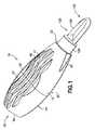
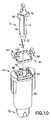
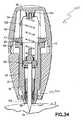
図1〜図3を参照すると、本発明の実施形態によるランセット装置10が概略的に示されている。ランセット装置10は、概して、ハウジング12と、ハウジング12に移動可能に関連付けられたシールド14と、その内部に配置されたランセット構造体70とを含む。本明細書にさらに詳細に考察するように、シールド14は、ハウジング12に同軸にかつ移動可能に関連付けられ、ハウジング12内に部分的に配置され、ハウジング12から部分的に外側に延在しており、ランセット構造体70は、シールド14内に収容され、かつシールド14を通して軸方向にまたは長手方向に移動可能である。  Referring to FIGS. 1-3, alancet device 10 according to an embodiment of the present invention is schematically illustrated. Thelancet device 10 generally includes ahousing 12, ashield 14 movably associated with thehousing 12, and alancet structure 70 disposed therein. As discussed in further detail herein, theshield 14 is coaxially and movably associated with thehousing 12, partially disposed within thehousing 12, and extends partially outwardly from thehousing 12. Thelancet structure 70 is housed within theshield 14 and is movable axially or longitudinally through theshield 14.

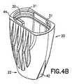
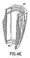
ハウジング12は、細長い本体を画定し、望ましくは、先端部分、すなわち前端部分22を画定する本体20と、基端部分、すなわち後端部分26を画定する後部キャップ24とで形成されている。本明細書においてさらに詳細に考察するように、ハウジング12の内部は、図4Cに示すように、概して開放され、内部空洞28を画定し、内部空洞28は、後部キャップ24により後端部で閉鎖され、シールド14が延在する、前端部分22を貫通する開口部30を含む。本体20および後部キャップ24は、一体形成することができる。別法として、本体20および後部キャップ24は、互いに取り付けられてハウジング12を形成する別個の要素であり、それはランセット装置10の組立てに役立つ。図4A〜図4Eおよび図5A〜図5Eは、こうした実施形態の例におけるそれぞれ本体20および後部キャップ24を示す。本体20および後部キャップ24は、適切な接着剤によって互いに取り付けることができ、または摩擦嵌めもしくはスナップフィット構造等、これらの間に機械的取付けを提供する相互係合構造を含むことができる。たとえば、本体20は、環状溝32を画定する環状リム31を含むことができ、後部キャップ24は、嵌合面に環状リップ34を有する環状突出部33を含むことができる。本体20および後部キャップ24が嵌合すると、環状突出部33は本体20の後部開放端内に延在し、環状リップ34は、本体20の環状リム31上にかつ環状溝32内にスナップフィットする。こうした要素の配置は、単に例示的なものであり、逆にされ得ることが理解されるべきであり、他の相互嵌合(inter−fitting)係合構造を用いて、本体20に後部キャップ24を取り付けられ得ることが企図される。代替的な実施形態では、本体20および後部キャップ24は、一体形成された構造体とすることができ、したがって、1つの構成要素として合わせて成形することができる。  Thehousing 12 defines an elongate body, and is desirably formed of abody 20 defining a distal orfront end portion 22 and arear cap 24 defining a proximal orrear end portion 26. As discussed in further detail herein, the interior of thehousing 12 is generally open and defines aninterior cavity 28, which is closed at the rear end by arear cap 24, as shown in FIG. 4C. And includes anopening 30 through thefront end portion 22 through which theshield 14 extends. Thebody 20 and therear cap 24 can be integrally formed. Alternatively,body 20 andrear cap 24 are separate elements that are attached to one another to formhousing 12, which aids in assemblinglancet device 10. 4A-4E and 5A-5E show thebody 20 and therear cap 24, respectively, in an example of such an embodiment. Thebody 20 and therear cap 24 can be attached to each other by a suitable adhesive, or can include an interengaging structure that provides a mechanical attachment therebetween, such as a friction or snap fit structure. For example, thebody 20 can include anannular rim 31 defining anannular groove 32, and therear cap 24 can include anannular protrusion 33 having anannular lip 34 on a mating surface. When thebody 20 and therear cap 24 are mated, theannular protrusion 33 extends into the rear open end of thebody 20 and theannular lip 34 snaps onto theannular rim 31 of thebody 20 and into theannular groove 32. . It should be understood that the arrangement of such elements is merely exemplary and can be reversed, and that therear cap 24 can be attached to thebody 20 using other inter-fitting engagement structures. It is contemplated that can be attached. In an alternative embodiment, thebody 20 and theback cap 24 can be a unitary structure and thus can be molded together as one component.

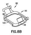
図11Bに示すように、本体20および後部キャップ24によって画定される概して長細いハウジング12は、対向する側部35、36を有し、それらは各々、つまみ用陥凹部37、38等、使用者の指に適応する面を含むことができる。ハウジング12に2つの対向するつまみ用陥凹部37、38が設けられているが、本発明によって、ハウジング本体20に形成された1つのつまみ用陥凹部37のみを設け得ることが理解されよう。つまみ用陥凹部37、38は、ハウジング12の外面の凹状窪みまたは凹部として形成され得る。さらに、後部キャップ24の上面等のハウジング12の後端部26もまた、図1および図2に示すような後部つまみ用陥凹部39等、凹状窪みまたは凹部として形成することができる使用者の指に適応する面を含むことができる。側部つまみ用陥凹部37、38および後部つまみ用陥凹部39は、使用者がランセット装置10を操作し、血液を採り、抜き取りまたは採取する処置においてランセット装置10を使用するのを補助する、実質的に使用者の指先に沿う人間工学的形状の面を提供し、使用者に複数のつまみ位置を提供することができる。図11Bに示すように、側部つまみ用陥凹部37、38は、双曲線により形成された輪郭として表すことができる。たとえば、双曲線は、主ハウジングを画定する対称面と実質的に同一平面上の位置で交差する2つの漸近線を含むことができる。さらに、図11Bに示すように、後部キャップ24は、双曲線により形成された輪郭を含むことができる。図1および図2を参照すると、ハウジング12は、ハウジング12に沿って延在しかつハウジング12と一体形成された複数の長手方向リブ40およびトラフ41等、ハウジング12と使用者の指先との間の把持を全体的に改善する構造をさらに含むことができ、それは、使用者に視覚的および触覚的手がかりを与えて指先を置く場所を使用者に教示することができる。ハウジング12は、前端部22に配置された少なくとも1つ、任意選択的に2つ以上の周縁陥凹部42をさらに含むことができる。1つの特定の実施形態では、2005年5月6日に出願され、「Contact Activated Lancet Device」という名称である、本出願と共通の譲受人に譲渡された米国特許出願公開第2006/0052809号明細書に開示された特徴に従ってランセット装置を構成することができ、上記出願の開示内容全体は参照により本明細書に明示的に組み込まれる。  As shown in FIG. 11B, the generally elongatehousing 12 defined by thebody 20 and therear cap 24 has opposingsides 35, 36, each of which may be a user recess, such as atab recess 37, 38. May be included to accommodate the finger. Although thehousing 12 is provided with two opposing knob recesses 37, 38, it will be understood that according to the present invention, only oneknob recess 37 formed in thehousing body 20 may be provided. The knob recesses 37, 38 may be formed as concave recesses or recesses on the outer surface of thehousing 12. In addition, therear end 26 of thehousing 12, such as the top surface of therear cap 24, can also be formed as a concave depression or recess, such as arear knob recess 39 as shown in FIGS. May be included. The side knob recesses 37, 38 and therear knob recess 39 are provided to assist a user in operating thelancet device 10 and using thelancet device 10 in a procedure for drawing, drawing or collecting blood. It is possible to provide an ergonomically shaped surface along the user's fingertip, and to provide the user with a plurality of knob positions. As shown in FIG. 11B, the side knob recesses 37, 38 can be represented as contours formed by hyperbolas. For example, the hyperbola may include two asymptotes that intersect at substantially co-planar locations with the plane of symmetry defining the main housing. Further, as shown in FIG. 11B, therear cap 24 may include a contour formed by a hyperbola. Referring to FIGS. 1 and 2, thehousing 12 includes a plurality oflongitudinal ribs 40 andtroughs 41 extending along and integrally formed with thehousing 12, such as between thehousing 12 and a user's fingertip. Can further include structures that improve the overall grip of the device, which can provide visual and tactile cues to the user and teach the user where to place his fingertips. Thehousing 12 can further include at least one, and optionally two or moreperipheral recesses 42 located at thefront end 22. In one particular embodiment, U.S. Patent Application Publication No. 2006/0052809, filed May 6, 2005, and assigned to a common assignee with the present application, entitled "Contact Activated Lancet Device" The lancet device can be configured according to the features disclosed herein, the entire disclosure of which is expressly incorporated herein by reference.

上述したように、シールド14は、ハウジング12の前端部を通って開口部30から外側に延在する。図6A〜図6Fに示すように、シールド14は、前端部52と後端部54との間に延在するシールド本体50を画定し、かつ内部を通して延在する内部空洞56を画定する、概して円筒状の中空構造体である。本明細書においてより詳細に考察するように、シールド本体50の前端部52は、使用者がランセット装置10を作動させると穿刺要素が延在する前方開口部60を含む前端壁58を画定する。前端壁58は、概して、先端開口部60の周囲に、穿刺要素によって穿刺されるべき使用者の身体の意図された領域に接触する小さい接触領域を画定する。シールド14に形成された複数の周縁陥凹部62を設けることによって、縮小した接触領域をより小さくする(すなわち、面積を縮小する)ことができる。より詳細に考察するように、周縁陥凹部62はまた、使用者が、概してランセット装置10の照準を定め、特にランセットの穿刺要素の照準を定める際に視覚的に補助するように、ターゲット指標も提供することができる。周縁陥凹部62は、概して、ハウジング12に設けられた周縁陥凹部42に類似している。周縁陥凹部42は、シールド14の外周部に配置され、シールド14の周囲に等間隔で配置され得る。周縁陥凹部42により、使用者は、穿刺要素の適切な吐出点の位置を視覚的に容易に特定することができ、それによりランセット装置10の照準特性が改善され、皮膚穿刺操作中に最適な血流が確保される。  As described above, theshield 14 extends outwardly from theopening 30 through the front end of thehousing 12. As shown in FIGS. 6A-6F, theshield 14 defines ashield body 50 extending between afront end 52 and arear end 54 and defines aninternal cavity 56 extending therethrough, generally. It is a cylindrical hollow structure. As will be discussed in more detail herein, thefront end 52 of theshield body 50 defines afront end wall 58 that includes afront opening 60 through which the piercing element extends when a user activates thelancet device 10. Thefront end wall 58 generally defines a small contact area around the tip opening 60 that contacts the intended area of the user's body to be punctured by the piercing element. By providing the plurality ofperipheral recesses 62 formed in theshield 14, the reduced contact area can be made smaller (that is, the area can be reduced). As will be discussed in more detail, theperipheral recess 62 also provides a target indicator to assist the user in aiming thelancet device 10 in general, and particularly in aiming the puncture element of the lancet. Can be provided.Peripheral recess 62 is generally similar toperipheral recess 42 provided inhousing 12. Theperipheral recesses 42 are arranged on the outer periphery of theshield 14 and may be arranged around theshield 14 at equal intervals. Theperipheral recess 42 allows the user to easily and visually locate the appropriate discharge point of the piercing element, thereby improving the aiming characteristics of thelancet device 10 and providing optimal puncturing during a skin piercing operation. Blood flow is secured.

上述したように、シールド14は、ハウジング12内で軸方向または長手方向に移動可能である。したがって、シールド14およびハウジング12は、ハウジング12を通してシールド14を案内するための対応する案内面を含むことができる。たとえば、シールド本体50は、シールド本体50の外面に沿って延在し、その間に案内チャネル64を形成する長手方向突出部63の対を含むことができる。ハウジング12は、案内チャネル64内に嵌まる、ハウジング12の本体20内の案内タブ44(図4B〜図4E)等の対応する構造を含むことができる。望ましくは、シールド本体50は、シールド本体50の対向する側部に沿って長手方向に延在する案内チャネル64の対を含み、ハウジング12は、案内チャネル64の各々に対応する本体20の対向する内面に案内タブ44の対を含む。案内タブおよび案内チャネルの配置を逆にすることができ、他の案内面を使用することも可能であることが企図される。案内タブ44および案内チャネル64は、シールド本体50がハウジング12内で適切に位置合せされることを確実にし、ハウジング12内でのシールド本体50の軸方向の摺動運動をもたらし、望ましくは回転運動を防止または阻止する。さらに、シールド本体50は、ハウジング12の本体20内での案内タブ44の上面と締まり嵌め係合するために、シールド本体50の後端部に棚状突起66を含むことができる。別法としてまたはそれに加えて、シールド本体50は、その前端部に向かう前方肩部69を含むことができ、ハウジング12の本体20は、前方リム面48を含むことができ(図4Dおよび図4E)、それらの間に締まり嵌め係合をもたらす。こうした締まり嵌め係合構造により、シールド本体50は、開口部30を通ってハウジング12から完全に出るように軸方向に摺動することが防止される。  As mentioned above, theshield 14 is axially or longitudinally movable within thehousing 12. Accordingly, shield 14 andhousing 12 may include corresponding guide surfaces for guidingshield 14 throughhousing 12. For example, theshield body 50 can include a pair oflongitudinal protrusions 63 extending along an outer surface of theshield body 50 and forming aguide channel 64 therebetween. Thehousing 12 may include a corresponding structure, such as a guide tab 44 (FIGS. 4B-4E) in thebody 20 of thehousing 12 that fits within theguide channel 64. Desirably, theshield body 50 includes a pair ofguide channels 64 extending longitudinally along opposing sides of theshield body 50, and thehousing 12 opposes thebody 20 corresponding to each of theguide channels 64. The inner surface includes a pair ofguide tabs 44. It is contemplated that the arrangement of the guide tabs and guide channels can be reversed, and that other guide surfaces can be used. Theguide tabs 44 and theguide channels 64 ensure that theshield body 50 is properly aligned within thehousing 12 and provide for an axial sliding movement of theshield body 50 within thehousing 12 and preferably a rotational movement. To prevent or prevent. Further,shield body 50 may include aledge 66 at the rear end ofshield body 50 for an interference fit with the upper surface ofguide tab 44 withinbody 20 ofhousing 12. Alternatively or additionally,shield body 50 may include aforward shoulder 69 toward its front end, andbody 20 ofhousing 12 may include a forward rim surface 48 (FIGS. 4D and 4E). ), Providing an interference fit between them. With such an interference fit structure, theshield body 50 is prevented from sliding in the axial direction so as to completely exit thehousing 12 through theopening 30.

ハウジング12およびシールド14は、それらの間に延在する、起動後にシールド14をハウジング12に対して固定関係で維持するロック構造をさらに含むことができる。たとえば、シールド本体50は、後端部54において、本体20または後部キャップ24との摩擦係合または相互嵌合係合する構造を含むことができる。たとえば、シールド本体50は、その後端部54に延在する、後部キャップ24の内面内のロック凹部29(図5A、図5Bおよび図5E)と相互嵌合係合するロックフィンガ59を含むことができる。  Housing 12 andshield 14 may further include a locking structure extending therebetween that maintainsshield 14 in fixed relation tohousing 12 after activation. For example, theshield body 50 may include a structure at therear end 54 that frictionally or interfits with thebody 20 or therear cap 24. For example, theshield body 50 may include a lockingfinger 59 that extends to therear end 54 and interlocks with a locking recess 29 (FIGS. 5A, 5B and 5E) in the inner surface of therear cap 24. it can.

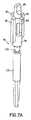
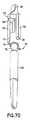
ランセット装置10は、ハウジング12内に配置されかつシールド14を通って延在するランセット構造体70をさらに含む。図7A〜図7Eに示すように、ランセット構造体70は、前端部に穿刺端部74を画定するランセット72の形態で示される穿刺要素を含む。ランセット装置10の使用に関して本明細書においてさらに考察するように、ランセット構造体70は、穿刺端部74がシールド本体50内に維持されている初期作動可能(armed)位置から、穿刺端部74がシールド本体50の前方開口部60を越えて延在する穿刺位置までの間で、シールド本体50の内部空洞56を通って軸方向または長手方向に移動するように適合される。  Lancet device 10 further includes alancet structure 70 disposed withinhousing 12 and extending throughshield 14. As shown in FIGS. 7A-7E, thelancet structure 70 includes a piercing element shown in the form of alancet 72 that defines a piercingend 74 at a front end. As discussed further herein with respect to the use oflancet device 10,lancet structure 70 allows piercingend 74 to move from an initially armed position in which piercingend 74 is maintained withinshield body 50. It is adapted to move axially or longitudinally through theinternal cavity 56 of theshield body 50 up to a puncturing position extending beyond thefront opening 60 of theshield body 50.

穿刺端部74は、患者の皮膚を穿刺するように適合され、先の尖った端部、刃先等を画定することができる。穿刺端部74は、刃の先の尖った端部が所定の向きに位置合せされる等、好ましい位置合せ向きを含むことができる。こうした実施形態では、シールド本体50および/またはハウジング12の本体20は、穿刺端部74の位置合せ向きに対応するターゲット指標を含むことができる。シールド本体50の陥凹部62および/または本体20の陥凹部42は、こうした位置合せ向きとして機能することができる。  The piercingend 74 is adapted to pierce the patient's skin and may define a pointed end, a cutting edge, or the like. The piercingend 74 may include a preferred alignment orientation, such that the pointed end of the blade is aligned in a predetermined orientation. In such embodiments, theshield body 50 and / or thebody 20 of thehousing 12 may include a target indicator corresponding to the alignment orientation of the piercingend 74. Therecess 62 in theshield body 50 and / or therecess 42 in thebody 20 can function as such an alignment orientation.

ランセット構造体70は、後端部にランセット72を支持するキャリア要素76をさらに含む。キャリア要素76およびシールド本体50は、ランセット構造体70を案内するための対応する案内面を含むことができる。たとえば、キャリア要素76は、その外面に案内タブ78を含むことができ、シールド本体50は、案内タブ78を内部に摺動可能に収容する、シールド本体59の内面に沿って長手方向に延在する対応する案内チャネル80(図6Cならびに図6Eおよび図6F)を含む。望ましくは、キャリア要素76は、その対向する側面に案内タブ78の対を含み、シールド本体50は、案内タブ78の各々に対応する、シールド本体50の対向する内面に沿って延在する案内チャネル80の対応する対を含む。案内タブおよび案内チャネルの配置を逆にすることができ、他の案内面を使用することも可能であることが企図される。案内タブ78および案内チャネル80は、ランセット構造体70がシールド本体50内で適切に位置合せされることを確実にし、シールド本体50内でのランセット構造体70の軸方向の摺動運動をもたらし、回転運動を防止または阻止することができる。案内タブ78の底面81は、案内チャネル80の底面に当接する当接面を提供して、ランセット構造体70が、前方開口部60を通ってシールド本体50から完全に出るように軸方向に移動するのを防止する。  Lancet structure 70 further includes acarrier element 76 that supports alancet 72 at a rear end. Thecarrier element 76 and theshield body 50 may include corresponding guide surfaces for guiding thelancet structure 70. For example, thecarrier element 76 can include aguide tab 78 on its outer surface, and theshield body 50 extends longitudinally along an inner surface of theshield body 59 that slidably houses theguide tab 78 therein. Corresponding guiding channels 80 (FIGS. 6C and 6E and 6F). Desirably, thecarrier element 76 includes a pair ofguide tabs 78 on opposite sides thereof, and theshield body 50 has guide channels extending along opposing inner surfaces of theshield body 50 corresponding to each of theguide tabs 78. Includes 80 corresponding pairs. It is contemplated that the arrangement of the guide tabs and guide channels can be reversed, and that other guide surfaces can be used. Theguide tab 78 and theguide channel 80 ensure that thelancet structure 70 is properly aligned within theshield body 50 and provide for an axial sliding movement of thelancet structure 70 within theshield body 50; Rotational movement can be prevented or prevented. Thebottom surface 81 of theguide tab 78 provides an abutment surface that abuts the bottom surface of theguide channel 80 such that thelancet structure 70 moves axially such that thelancet structure 70 completely exits theshield body 50 through thefront opening 60. To prevent

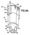
図10に示すように、シールド本体50の後端部54に示す、保持ハブ90がさらに設けられる。保持ハブ90は、望ましくは、シールド本体50の後端部54内に配置または保持される別個の構造体として設けられる。たとえば、シールド本体50は、後端部54の上面内に延在する凹部68等、保持ハブ90を収容する構造を含むことができる。このように、保持ハブ90は、凹部68内に載置される。他の実施形態では、シールド本体50は、組立てを補助するように保持ハブ90を支持しかつ位置決めするための面を含むことができる。さらに、本発明の他の実施形態では、保持ハブ90の機能要素をシールド本体50上に直接成形するか、または形成することができる。  As shown in FIG. 10, a holdinghub 90 is further provided at therear end 54 of theshield body 50. The retaininghub 90 is desirably provided as a separate structure disposed or retained within therear end 54 of theshield body 50. For example, theshield body 50 can include a structure that houses the retaininghub 90, such as arecess 68 that extends into the upper surface of therear end 54. Thus, the holdinghub 90 is placed in therecess 68. In other embodiments, theshield body 50 can include a surface for supporting and positioning the retaininghub 90 to assist in assembly. Further, in other embodiments of the present invention, the functional elements of the holdinghub 90 can be molded or formed directly on theshield body 50.

保持ハブ90は、ランセット構造体70を、ハウジング12内に後退した初期作動可能位置に保持するレバー構造体を画定する。特に、図8A〜図8Dに示すように、保持ハブ90は、上面に肩部94および接触面96を含む枢支レバー要素92を含み、その下面の肩部94と接触面96との間にピボットヒンジ98がある。例として、レバー要素92は、シーソーのように、支点または枢支点が力と荷重との間に配置されたクラス1のレバーを画定する。たとえば、レバー要素92の上面は、接触面96と対向する肩部94を含み、ピボットヒンジ98が、肩部94と接触面96との間の支点を提供する。このように、本明細書においてより詳細に記載するように、肩部94上に載置されているランセット構造体70によって表される荷重が、接触面96に加えられる力から分離され、ピボットヒンジ98の支点が力と荷重との間に配置される。  Retention hub 90 defines a lever structure that retainslancet structure 70 in a retracted, initial, operable position withinhousing 12. In particular, as shown in FIGS. 8A-8D, the retaininghub 90 includes apivot lever element 92 that includes ashoulder 94 and acontact surface 96 on the upper surface, between theshoulder 94 and thecontact surface 96 on the lower surface. There is apivot hinge 98. By way of example,lever element 92 defines aclass 1 lever with a fulcrum or pivot point positioned between force and load, such as a seesaw. For example, the upper surface oflever element 92 includes ashoulder 94opposite contact surface 96, and pivot hinge 98 provides a fulcrum betweenshoulder 94 andcontact surface 96. Thus, as described in more detail herein, the load represented by thelancet structure 70 resting on theshoulder 94 is separated from the force applied to thecontact surface 96 and the pivot hinge 98 fulcrums are located between the force and the load.

図8A〜図8Dに示すように、一実施形態において、枢支される概して楔形状の構造体として、レバー要素92を設けることができ、楔の底部の点が、レバーの枢動のためのピボットヒンジ98の支点として作用する。保持ハブ90は、環状リム100を含むことができ、少なくとも1つのレバー要素92が、ピボットヒンジ98によって環状リム100上に支持され、かつそれに枢動可能にヒンジ式に接続されている。保持ハブ90は、典型的には、環状リム100の上面のその対向する側部において枢動可能にヒンジ式に接続されたレバー要素92の対を含む。本明細書では、環状リム100は、内部開口部を画定するように周方向にまたは外周部に延在する、湾曲したコーナー接続部を有する概して矩形のリング状構造体として示す。本明細書で用いる「環状」という用語は、湾曲したコーナー接続部または角のあるコーナー接続部を含む、円形であるか、湾曲しているか、または多角形である任意のリング状構造体または帯状構造体を包含するように意図される。不連続の環状構造体を有する溝付き座金またはスリップオン座金に類似した構造体等、他の環状のただし不完全なリング状構造体または帯状構造体を用い得ることも企図される。  As shown in FIGS. 8A-8D, in one embodiment, alever element 92 can be provided as a pivotally supported, generally wedge-shaped structure, wherein the point at the bottom of the wedge provides for pivoting of the lever. Acts as a fulcrum for thepivot hinge 98. The retaininghub 90 can include anannular rim 100 with at least onelever element 92 supported on theannular rim 100 by apivot hinge 98 and pivotally hingedly connected thereto.Retention hub 90 typically includes a pair oflever elements 92 pivotally hingedly connected on opposite sides of the upper surface ofannular rim 100. Here, theannular rim 100 is shown as a generally rectangular ring-like structure having curved corner connections that extend circumferentially or circumferentially to define an internal opening. As used herein, the term "annular" refers to any ring-shaped structure or band that is round, curved, or polygonal, including curved or angular corner connections. It is intended to encompass the structure. It is also contemplated that other annular but incomplete ring or band structures may be used, such as structures similar to grooved or slip-on washers with discontinuous annular structures.

保持ハブ90およびランセット構造体70は、互いに締まり嵌め係合しており、それにより、保持ハブ90は、ランセット構造体70を、ハウジング12内に後退した初期作動可能位置に保持する。たとえば、キャリア要素76は、そこから横方向に延在するフィンガ82を含むことができ、フィンガ82の底面上に支持面83を含む(図7Dおよび図7E)。フィンガ82の支持面83は、レバー要素92の肩部94に載置され、それによりランセット構造体70と保持ハブ90との間に締まり嵌め係合がもたらされる。  The retaininghub 90 and thelancet structure 70 are in interference fit with each other, such that the retaininghub 90 retains thelancet structure 70 in thehousing 12 in the retracted, initial ready position. For example, thecarrier element 76 can include afinger 82 extending laterally therefrom and include asupport surface 83 on the bottom surface of the finger 82 (FIGS. 7D and 7E). Thesupport surface 83 of thefinger 82 rests on theshoulder 94 of thelever element 92, thereby providing an interference fit between thelancet structure 70 and the holdinghub 90.

さらに、レバー要素92の接触面96は、ハウジング12内に画定された構造体と接触係合するように適合される。たとえば、ハウジング12の後部キャップ24は、一体形成されかつ少なくとも1つ望ましくは2つの対向する内側側壁上に延在する内部接触部46等、内部に延在する構造体を含むことができる(図5B、図5Cおよび図5E)。各々の内部接触部46は、カム面を形成する、レバー要素92の接触面96との接触係合する係合面47を含む。1つの実施形態において、接触面96は、略ロッド形状部分97を含み、後部キャップ24の内面は、内壁面上にかつ内壁面の各々の対向する側部上に互いに隣接するように延在する内部接触部46の対を含む。このように、内部接触部46の対が、接触面96のロッド形状部分97の両端に係合し、それにより、レバー要素92の枢動中、ロッド形状部分97の外周部に連続的なカム状接触面が提供される。図8Eに示す代替的な実施形態では、接触面96は、上述した略ロッド形状部分とは対照的に、面取り部分を形成する角度付き面197を含むことができる。角度付き面197により形成されたこのような面取り部分は、従来の射出成形手順で保持ハブ90を形成する成形作業において特に有用である。こうした実施形態では、後部キャップ24の内部接触部46の対が、接触面96の角度付き面197により形成された面取り部分の両端に係合し、上述したようなカム状接触面を提供する。  Further, thecontact surface 96 of thelever element 92 is adapted for contacting engagement with a structure defined within thehousing 12. For example, therear cap 24 of thehousing 12 can include an internally extending structure, such as aninner contact 46 that is integrally formed and extends on at least one, and preferably two, opposing inner sidewalls (FIG. 5B, 5C and 5E). Eachinternal contact 46 includes anengagement surface 47 that forms a camming surface in contact engagement with acontact surface 96 of alever element 92. In one embodiment, thecontact surface 96 includes a generally rod-shapedportion 97 and the inner surface of therear cap 24 extends adjacent to each other on the inner wall surface and on each opposing side of the inner wall surface. Includes a pair ofinternal contacts 46. In this way, the pair ofinternal contacts 46 engage the ends of the rod-shapedportion 97 of thecontact surface 96 so that during pivoting of the lever element 92 a continuous cam is provided on the outer periphery of the rod-shapedportion 97. A contact surface is provided. In the alternative embodiment shown in FIG. 8E, thecontact surface 96 can include anangled surface 197 that forms a chamfered portion, as opposed to the generally rod-shaped portion described above. Such a chamfer formed byangled surface 197 is particularly useful in a molding operation to form retaininghub 90 in a conventional injection molding procedure. In such an embodiment, a pair ofinternal contact portions 46 of therear cap 24 engage opposite ends of the chamfer formed by theangled surface 197 of thecontact surface 96 to provide a cam-like contact surface as described above.

さらに、レバー要素92は、典型的には、ランセット装置10およびランセット構造体70の移動方向を概して画定する略長手方向軸Aに対する断面で環状リム100を切開する、図8Dにおいて面Yに示す面の一方の側に配置される。このように、レバー要素92が外側に枢動するとき、ピボットヒンジ98により画定される支点等の支点は、環状リム100の上面等の面Yの上方に低い断面二次モーメントを表し、レバー要素92、すなわちピボットヒンジ98の塑性変形を引き起こす。こうした塑性変形は、恒久的な可能性があり、それにより、レバー要素は、枢動後にその形状および位置を維持する。  Further, thelever element 92 typically cuts theannular rim 100 in a cross-section relative to a generally longitudinal axis A that generally defines the direction of movement of thelancet device 10 and thelancet structure 70, the plane shown in plane Y in FIG. 8D. Is arranged on one side. Thus, when thelever element 92 pivots outward, the fulcrum, such as the fulcrum defined by thepivot hinge 98, represents a low second moment of area above a surface Y, such as the upper surface of theannular rim 100, 92, ie, the plastic deformation of thepivot hinge 98. Such plastic deformation can be permanent, so that the lever element maintains its shape and position after pivoting.

ランセット装置10を通るランセット構造体70の移動は、駆動ばね102により与えられる付勢力によって達成される(図11C〜図18)。駆動ばね102は、ランセット構造体70に対して付勢力をかけて、ランセット構造体70を、装置を通して穿刺位置に向かわせるように適合され、ハウジング12の後端部とランセット構造体70との間に配置され得る。駆動ばね102は、ハウジング12の後端部とランセット構造体70との間に収容される別個の要素とすることができ、またはハウジング12および/もしくはランセット構造体70の一方もしくは両方と一体形成することができる。後部キャップ24は、駆動ばね102を適切な向きに位置合せしかつ/または維持する構造を含むことができる。図13において、たとえば、後部キャップ24は、駆動ばね102を収容する位置合せナブ(nub)104を含むことができる。ランセット構造体70はまた、ランセット構造体70のキャリア要素76から延在する後部ナブ86等、駆動ばね102の反対側の端部を収容する面または構造体を含むこともできる。駆動ばね102は、後部キャップ24の位置合せナブ104とキャリア要素76の後部ナブ86との間に延在する。ランセット構造体70が作動可能位置にあるとき、駆動ばね102は、ハウジング12の後端部とランセット構造体70との間等においてランセット構造体に対して力をかけ、ランセット構造体70を穿刺位置に向かって付勢する。シールド本体50およびレバー要素92は、駆動ばね102によってランセット構造体70および肩部94に対して加えられる付勢力に関わらず、レバー要素92がピボットヒンジ98の周囲に反対方向に枢動するのを防止する相互係合構造を含むことができる。たとえば、楔形状のレバー要素92から形成された底部の角度付き面99(図8C〜図8E)は、シールド本体50の後端部54における対応する角度付きナブ55(図6Dおよび図6F)と係合しかつそれに当接することができる。こうした相互係合面は、駆動ばね102から加えられるいかなる力も、反対方向、すなわち肩部94がシールド本体50の内部空洞56内に下方に枢動する方向に、レバー要素92をピボットヒンジ98の周囲で枢動させることを防止する。任意選択的にまたはそれに加えて、上述したようなピボットヒンジ98の塑性変形を恒久的なものとすることができ、それにより、レバー要素92が反対方向に自動的に枢動することが防止され、ランセット構造体70を、作動後に肩部94上に載置されている作動前状態に再設定することができる。  Movement of thelancet structure 70 through thelancet device 10 is achieved by the biasing force provided by the drive spring 102 (FIGS. 11C-18). Thedrive spring 102 is adapted to apply a biasing force on thelancet structure 70 to cause thelancet structure 70 to be directed through the device to a puncturing position, and between the rear end of thehousing 12 and thelancet structure 70. May be arranged. Thedrive spring 102 may be a separate element housed between the rear end of thehousing 12 and thelancet structure 70 or may be integrally formed with one or both of thehousing 12 and / or thelancet structure 70. be able to. Therear cap 24 can include features that align and / or maintain thedrive spring 102 in the proper orientation. In FIG. 13, for example, therear cap 24 can include analignment nub 104 that houses thedrive spring 102. Thelancet structure 70 may also include a surface or structure that houses the opposite end of thedrive spring 102, such as arear nub 86 extending from thecarrier element 76 of thelancet structure 70.Drive spring 102 extends betweenalignment nub 104 onrear cap 24 andrear nub 86 oncarrier element 76. When thelancet structure 70 is in the operable position, thedrive spring 102 exerts a force on the lancet structure, such as between the rear end of thehousing 12 and thelancet structure 70, and moves thelancet structure 70 to the puncturing position. Energize toward. Theshield body 50 and thelever element 92 allow thelever element 92 to pivot about thepivot hinge 98 in the opposite direction regardless of the biasing force exerted by thedrive spring 102 on thelancet structure 70 and theshoulder 94. Preventing interengaging structures may be included. For example, the bottom angled surface 99 (FIGS. 8C-8E) formed from the wedge-shapedlever element 92 is in contact with the corresponding angled nub 55 (FIGS. 6D and 6F) at therear end 54 of theshield body 50. It can engage and abut it. Such interengaging surfaces cause thelever element 92 to pivot about thepivot hinge 98 in the opposite direction, i.e., in the direction in which theshoulder 94 pivots downwardly into theinterior cavity 56 of theshield body 50, when any force applied by thedrive spring 102. To prevent pivoting. Optionally or additionally, the plastic deformation of thepivot hinge 98 as described above can be permanent, thereby preventing thelever element 92 from automatically pivoting in the opposite direction. , Thelancet structure 70 can be reset to a pre-actuation state resting on theshoulder 94 after actuation.

図3を参照すると、ランセット装置10の前端部に引戻しばね110をさらに設けることができ、それは、ランセット構造体70が穿刺位置に軸方向に移動した後に、ランセット構造体70をシールド本体50内に後退させる。引戻しばね110は、典型的には、ランセット構造体70のキャリア要素76の前面とシールド本体50の前端壁58内の内面との間に延在する。引戻しばね110は、典型的には圧縮ばねであり、圧縮状態にあるときにエネルギーを蓄積することができる。  Referring to FIG. 3, aretraction spring 110 may further be provided at the front end of thelancet device 10, which moves thelancet structure 70 into theshield body 50 after thelancet structure 70 has been axially moved to the puncturing position. Retreat. Theretraction spring 110 typically extends between the front surface of thecarrier element 76 of thelancet structure 70 and the inner surface within thefront end wall 58 of theshield body 50. Theretraction spring 110 is typically a compression spring and can store energy when in a compressed state.

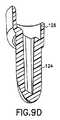
図1を参照すると、ランセット装置10は、ランセット装置10を使用前に保護するように覆う保護カバー120をさらに含むことができる。保護カバー120は、ランセット装置10の前端部に関連付けられたタブ部材122を含むことができ、シールド本体50の前端壁58の滅菌状態を維持する。図9A〜図9Fを参照すると、タブ部材122は、前方タブ部分124および垂下スカート126を含むことができる。垂下スカート126は、シールド本体50の前端部52と協働するように適合され、概して前端部52を取り囲むかまたは封入する。垂下スカート126は、ハウジング12の本体20の前端部22にも接触する。このように、タブ部材122は、本体20の前方開口部30およびシールド本体50の前方開口部60を閉鎖する。さらに、こうした構成は、本体20およびシールド本体50のそれぞれの前端部を互いに対して固定関係で維持し、それにより、ランセット装置10の時期尚早な起動を引き起こす可能性がある、それらの間の移動が防止される。  Referring to FIG. 1, thelancet device 10 may further include aprotective cover 120 for protecting thelancet device 10 before use. Theprotective cover 120 can include atab member 122 associated with the front end of thelancet device 10 to maintain the sterility of thefront end wall 58 of theshield body 50. Referring to FIGS. 9A-9F,tab member 122 may include afront tab portion 124 and a dependingskirt 126. The dependingskirt 126 is adapted to cooperate with thefront end 52 of theshield body 50 and generally surrounds or encloses thefront end 52. The dependingskirt 126 also contacts thefront end 22 of thebody 20 of thehousing 12. Thus, thetab member 122 closes thefront opening 30 of themain body 20 and thefront opening 60 of the shieldmain body 50. Further, such an arrangement maintains the respective front ends of thebody 20 and theshield body 50 in a fixed relationship with respect to each other, thereby causing premature activation of thelancet device 10 and movement between them. Is prevented.

保護カバー120の一部が、シールド本体50内に延在して、穿刺要素の少なくとも一部を取り囲むことができる。たとえば、図11Dに示すように、柱部分130が、シールド本体50の前方開口部60を通って、その内部空洞56内に延在して、穿刺要素、すなわちランセット72の少なくとも一部を保護するように包囲しかつ取り囲む。柱部分130およびタブ部材122は、一緒に取り付けられるか、または他の方法で保持される別個の要素とすることができる。たとえば、タブ部材122は、内部を通して柱部分130を収容する内部開口部を含むことができる。図7A〜図7Eを概して参照すると、柱部分130をランセット構造体70のキャリア要素76と一体形成し、ランセット72を完全に取り囲むことができ、それにより、使用前にランセット72の滅菌状態が維持される。柱部分130およびキャリア要素76は、それらの間の接合部に切欠き部分132を含むことができ、それは柱部分130を除去し、ランセット72を露出させるための破断点を提供する。別法として、剥離可能な医療グレード接着剤等を用いて、医療分野において慣例的な方法によって、柱部分130をランセット72に直接固定することができる。  A portion of theprotective cover 120 can extend into theshield body 50 and surround at least a portion of the piercing element. For example, as shown in FIG. 11D, apost portion 130 extends through thefront opening 60 of theshield body 50 and into itsinternal cavity 56 to protect at least a portion of the piercing element, ie, thelancet 72. Surround and surround.Post portion 130 andtab member 122 can be separate elements that are attached together or otherwise retained. For example,tab member 122 can include an internal opening that receivespost portion 130 therethrough. With reference generally to FIGS. 7A-7E, thepost portion 130 can be integrally formed with thecarrier element 76 of thelancet structure 70 to completely surround thelancet 72, thereby maintaining thelancet 72 in a sterile condition prior to use. Is done. Thepost portion 130 and thecarrier element 76 can include anotch 132 at the junction therebetween, which provides a break point for removing thepost portion 130 and exposing thelancet 72. Alternatively, thepost portion 130 can be secured directly to thelancet 72 using methods that are conventional in the medical arts, such as with a peelable medical grade adhesive or the like.

一実施形態では、後部キャップ24およびハウジング本体20は、嵌合する別個の構造体であり、ハウジング本体20がハウジング12の前部を形成し、後部キャップ24がハウジング12の実質的な後部を形成する。より詳細には、後部キャップ24は、ハウジングおよび後部キャップを合わせた完全な長手方向の長さによって測定したとき、ハウジング12をおよそ半分に分割する位置でハウジング本体20と嵌合する、ハウジング12のおよそ半分等のハウジング12の相当の部分を構成することができる。こうした構成により、ランセット装置10の簡略化された組立てが可能になり、それは、シールド14、ランセット構造体70、ならびに保持ハブ90、駆動ばね102、および任意選択的に引戻しばね110を含む保持要素および係合要素を含む内部構成要素を、ハウジング本体20内にその後端部から挿入することができ、挿入するために小さいサイズのハウジング本体20によって隙間を形成する必要がほとんどないためである。さらに、挿入後、ハウジング12全体に対して相対的に小さいサイズのハウジング本体20が提供する小さい隙間のために、こうした内部要素を容易に見ることができ、それによって、適切な位置合せを容易に視覚的に確保することができる。さらに、次いで、ハウジング12内の保持ハブ90の実質的に周縁の場所等の内部機能構成要素に隣接した場所において、後部キャップ24をハウジング本体20に取り付けることができる。また、ハウジング本体20および後部キャップ24は、ハウジング12の全長の実質的中間点で嵌合することができ、各々、ハウジング12の半分を実質的に画定する。このように、ハウジング本体20および後部キャップ24の嵌合により、つまみ用陥凹部37、38が実質的に分けられまたは二分される。  In one embodiment, therear cap 24 and thehousing body 20 are separate mating structures, with thehousing body 20 forming the front of thehousing 12 and therear cap 24 forming the substantial rear of thehousing 12. I do. More specifically, therear cap 24 fits into thehousing body 20 at a location that divides thehousing 12 approximately in half, as measured by the full longitudinal length of the housing and rear cap combined. A substantial portion ofhousing 12, such as approximately half, can be constructed. Such a configuration allows for a simplified assembly of thelancet device 10, which includes ashield 14, alancet structure 70, and a retaining element including a retaininghub 90, adrive spring 102, and optionally aretraction spring 110. This is because the internal components including the engagement elements can be inserted into thehousing body 20 from the rear end, and there is almost no need to form a gap with the small-sized housing body 20 for insertion. Further, after insertion, these small internal elements can be easily seen due to the small gap provided by the relatively smallsize housing body 20 relative to theentire housing 12, thereby facilitating proper alignment. It can be secured visually. Further, therear cap 24 can then be attached to thehousing body 20 at a location adjacent to an internal functional component, such as at a location substantially peripheral to the retaininghub 90 within thehousing 12. Also, thehousing body 20 and therear cap 24 can be fitted at substantially mid-points of the entire length of thehousing 12, each substantially defining one half of thehousing 12. Thus, the fitting of thehousing body 20 and therear cap 24 substantially separates or bisects the knob recesses 37 and 38.

本発明のランセット装置のそれぞれの要素はすべて、典型的には、医療グレードのプラスチック材料等の成形プラスチック材料で形成される。ランセット72は、皮膚を穿刺するように適合された任意の好適な材料から構成することができ、典型的には、ステンレス鋼等の外科グレード金属である。  All of the respective elements of the lancet device of the present invention are typically formed of a molded plastic material, such as a medical grade plastic material.Lancet 72 may be comprised of any suitable material adapted to pierce the skin, and is typically a surgical grade metal such as stainless steel.

ここで、概して図1〜図18、特に図11Dおよび図12〜図18を参照して、ランセット装置10の使用について説明する。使用前に、保護カバー120がシールド14をその前端部で覆っている状態で、図1および図11Dに示すようなランセット装置10が提供される。ランセット装置10、特にランセット構造体70は、初期作動前状態にあり、キャリア要素76のフィンガ82が、それと締まり嵌め係合しているレバー要素92の肩部94に当接し、またはその上に載置されている。このように、保持ハブ90のレバー要素92は、ハウジング12内のこの作動前位置にランセット構造体70を維持し、特に穿刺端部74をシールド本体50内に後退した状態で維持する。さらに、駆動ばね102が、ランセット構造体70とハウジング12の後部キャップ24との間に延在している。この作動前位置において、駆動ばね102は、弛緩状態である場合もあれば、完全に圧縮された状態である場合もある。より望ましくは、駆動ばね102は、この作動前位置において部分的に圧縮された状態にあり、後部キャップ24とランセット構造体70との間に付勢力をかけ、フィンガ82と肩部94との間の締まり嵌め係合が、こうした付勢力に抗してランセット構造体70を維持する。さらに、底部の角度付き面99と角度付きナブ55との間の相互係合面は、レバー要素92が、反対方向に枢動することを防止し、それによりランセット構造体70をシールド本体50内に押し通す。また、この状態において、保護カバー120が、ハウジング12に対するシールド14のあらゆる軸方向の移動を防止し、それによってランセット装置10の作動が防止される。  The use of thelancet device 10 will now be described with reference generally to FIGS. 1-18, particularly FIGS. 11D and 12-18. Prior to use, thelancet device 10 as shown in FIGS. 1 and 11D is provided with theprotective cover 120 covering theshield 14 at its front end. Thelancet device 10, and particularly thelancet structure 70, is in a pre-initial state, in which thefingers 82 of thecarrier element 76 abut or rest on theshoulders 94 of thelever element 92 in an interference fit therewith. Is placed. Thus, thelever element 92 of the retaininghub 90 maintains thelancet structure 70 in this pre-actuated position within thehousing 12, and in particular, maintains the piercingend 74 retracted within theshield body 50. Further, adrive spring 102 extends between thelancet structure 70 and therear cap 24 of thehousing 12. In this pre-actuation position, thedrive spring 102 may be in a relaxed state or in a fully compressed state. More desirably, thedrive spring 102 is in a partially compressed state in this pre-actuated position, and applies a biasing force between therear cap 24 and thelancet structure 70 to cause a force between thefinger 82 and theshoulder 94. The interference fit maintains thelancet structure 70 against such biasing forces. Further, the interengaging surface between the bottomangled surface 99 and theangled nub 55 prevents thelever element 92 from pivoting in the opposite direction, thereby moving thelancet structure 70 within theshield body 50 Through. Also, in this state, theprotective cover 120 prevents any axial movement of theshield 14 with respect to thehousing 12, thereby preventing the operation of thelancet device 10.

使用に向けてランセットアセンブリを準備するために、使用者は、ハウジング12を、対向する側部35、36において親指ともう1本の指との間等で把持し、図2に示すように前端部から保護カバー120を取り除き、それにより、ハウジング12の本体20の前端部から延在しているシールド本体50を露出させる。パドル形状の部材を含める等により、タブ部材122の前方タブ部分124を人間工学的に形成して、使用者が、タブ部材122を容易に操作しかつ必要な力またはトルクを加えて、垂下スカート126をシールド本体50の前端部52との摩擦係合から解放し、かつ切欠き132において柱部分130をキャリア要素76から破断させ、それによりランセット72から柱部分130を解放することができる。加えられる破断力は、本発明に従ったものであり、柱部分130とキャリア要素76との間の結合を破断し、垂下スカート126とシールド本体50との間の摩擦係合を解除するように適用される、個別のねじれ運動もしくは引張り運動、または組み合わされた「ねじれ」(すなわち、回転)運動および「引張り」運動とすることができる。  To prepare the lancet assembly for use, the user grips thehousing 12 at opposingsides 35, 36, such as between a thumb and another finger, and moves the front end as shown in FIG. Theprotective cover 120 is removed from the section, thereby exposing theshield body 50 extending from the front end of thebody 20 of thehousing 12. Thefront tab portion 124 of thetab member 122 is ergonomically formed, such as by including a paddle-shaped member, so that the user can easily manipulate thetab member 122 and apply the necessary force or torque to provide the hanging skirt. 126 may be released from frictional engagement with thefront end 52 of theshield body 50 and thepost 130 may be broken from thecarrier element 76 at thenotch 132, thereby releasing thepost 130 from thelancet 72. The applied breaking force is in accordance with the present invention to break the bond between thepost portion 130 and thecarrier element 76 and to release the frictional engagement between the dependingskirt 126 and theshield body 50. The applied twisting or pulling motions, or the combined “torsional” (ie, rotational) and “pulling” motions, can be applied.

次に、シールド本体50の前端壁58を、図13に示すような患者の皮膚表面S等、血流を開始させることが望まれる使用者の身体、または別人の身体の場所に接触させることができる。設けられる場合、陥凹部62のようなターゲット指標を所望の穿刺位置と位置合せすることができる。  Next, thefront end wall 58 of theshield body 50 is brought into contact with the location of the user's body or another person's body where it is desired to initiate blood flow, such as the patient's skin surface S as shown in FIG. it can. If provided, a target indicator, such as arecess 62, can be aligned with a desired puncture position.

身体に接して配置されると、使用者は、ハウジング12に下向きの力をかけ、シールド本体50を皮膚表面Sに押し付ける。特に、使用者は、後部キャップ24の後部つまみ用陥凹部39に矢印Xの方向の力を加え、それにより皮膚表面Sに力を加える。こうした力は、シールド本体50の前端壁58とハウジング12の後部キャップ24との間に対向する外部圧力を確立し、シールド本体50をハウジング12内に軸方向に移動させ、それによりシールド本体50の後端部54を後部キャップ24に向かって変位させる。案内タブ44および案内チャネル64によって提供される対応する案内面は、シールド本体50を、ハウジング12の本体20を通して軸方向に案内し、これらの間の適切な軸方向の位置合せを確実にする。  When placed in contact with the body, the user applies a downward force to thehousing 12 to press theshield body 50 against the skin surface S. In particular, the user applies a force in the direction of arrow X to therear knob recess 39 of therear cap 24, thereby applying a force to the skin surface S. These forces establish opposing external pressure between thefront end wall 58 of theshield body 50 and therear cap 24 of thehousing 12, causing theshield body 50 to move axially into thehousing 12, thereby causing theshield body 50 Therear end 54 is displaced toward therear cap 24. The corresponding guide surfaces provided by theguide tabs 44 and theguide channels 64 guide theshield body 50 axially through thebody 20 of thehousing 12 and ensure proper axial alignment therebetween.

保持ハブ90はシールド本体50の後端部54に隣接しているため、後部キャップ24の方向へのシールド本体50の後端部54のこうした変位は、後部キャップ24に向かう保持ハブ90の対応する後方移動を引き起こす。さらに、保持ハブ90のレバー要素92の肩部94とランセット構造体70のキャリア要素76のフィンガ82との間の締まり嵌め係合により、後部キャップ24に向かうランセット構造体70の対応する後方移動が引き起こされる。こうした移動により、駆動ばね102が圧縮される。初期作動前位置において駆動ばね102が弛緩状態にある実施形態では、駆動ばね102のこの圧縮によって、シールド本体50を通してランセット構造体70を穿刺位置まで軸方向前方に押し進めるのに十分な付勢力で駆動ばね102が作動状態になり、それにより、ランセット構造体70が作動可能位置になる。しかしながら、この時点で、ランセット構造体70は、フィンガ82と肩部94との間の締まり嵌め係合のために、穿刺端部74がシールド本体50内に後退するように依然として維持されている。初期作動前位置において駆動ばね102が部分的に圧縮された状態にある実施形態では、この駆動ばね102の圧縮により、シールド本体50を通してランセット構造体70を穿刺位置まで軸方向前方に完全に押し進めるのに十分な付加的な付勢ポテンシャルエネルギーで、駆動ばね102がさらに作動状態になる。この場合にも、この作動前の作動可能位置において、ランセット構造体70は、フィンガ82と肩部94との間の締まり嵌め係合に基づいて、穿刺端部74がシールド本体50内に後退するように依然として維持される。  Since the retaininghub 90 is adjacent therear end 54 of theshield body 50, such displacement of therear end 54 of theshield body 50 in the direction of therear cap 24 will correspond to a corresponding movement of the retaininghub 90 toward therear cap 24. Causes backward movement. Further, the interference fit between theshoulder 94 of thelever element 92 of the retaininghub 90 and thefinger 82 of thecarrier element 76 of thelancet structure 70 allows a corresponding rearward movement of thelancet structure 70 toward therear cap 24. Is caused. By such a movement, thedrive spring 102 is compressed. In embodiments where thedrive spring 102 is in a relaxed state in the initial pre-actuation position, this compression of thedrive spring 102 drives thelancet structure 70 with sufficient bias to push thelancet structure 70 axially forward through theshield body 50 to the puncturing position. Thespring 102 is activated, thereby bringing thelancet structure 70 into an operable position. However, at this point, thelancet structure 70 is still maintained such that the piercingend 74 is retracted into theshield body 50 due to the interference fit between thefinger 82 and theshoulder 94. In embodiments where thedrive spring 102 is partially compressed in the pre-initial position, the compression of thedrive spring 102 causes thelancet structure 70 to be pushed completely axially forward through theshield body 50 to the puncturing position. With sufficient additional biasing potential energy, thedrive spring 102 is further activated. Again, in the operable position prior to this actuation, thelancet structure 70 causes the piercingend 74 to retract into theshield body 50 due to an interference fit between thefinger 82 and theshoulder 94. So still maintained.

こうした後部キャップ24に向かうシールド本体50の軸方向または長手方向の移動中、キャリア要素76のフィンガ82がレバー要素92の肩部94上に載置された状態で、保持ハブ90も後部キャップ24に向かって後方に(すなわち基端側に)変位する。図13〜図14に示すように、こうした保持ハブ90の後方の移動により、後部キャップ24内の内部接触部46の係合面47のカム面が、ロッド形状部分97等のレバー要素92の対応する接触面96と係合し、協働する。したがって、対応するカム接触面が、ランセット装置10に対するアクチュエータ要素を提供する。レバー要素92が楔形状の輪郭であるために、こうした係合および協働により、レバー要素92が、環状リム100に対してピボットヒンジ98の周囲で枢動する。特に、肩部94が、環状リム100の概して半径方向内側に延在し、接触面96が概して環状リム100の外周部にある状態で、係合面47は、環状リム100の外周部において接触面96、特にロッド形状部分97と係合し、それにより、接触面96および肩部94を傾けることによって、レバー要素92がピボットヒンジ98の支点を中心に枢動し、ランセット構造体70を、環状リム100を通して、シールド本体50の内部空洞56内に解放する。  During such axial or longitudinal movement of theshield body 50 toward therear cap 24, the retaininghub 90 is also attached to therear cap 24 with thefinger 82 of thecarrier element 76 resting on theshoulder 94 of thelever element 92. Displaced rearward (ie, proximally). As shown in FIGS. 13 and 14, the rearward movement of the holdinghub 90 causes the cam surface of theengagement surface 47 of theinternal contact portion 46 in therear cap 24 to correspond to thelever element 92 such as the rod-shapedportion 97. And cooperate with thecorresponding contact surface 96. Accordingly, a corresponding cam contact surface provides an actuator element for thelancet device 10. Such engagement and cooperation causes thelever element 92 to pivot about thepivot hinge 98 with respect to theannular rim 100 because thelever element 92 has a wedge-shaped profile. In particular, with theshoulder 94 extending generally radially inward of theannular rim 100 and thecontact surface 96 generally at the outer periphery of theannular rim 100, theengagement surface 47 By engaging asurface 96, in particular a rod-shapedportion 97, thereby tilting thecontact surface 96 and theshoulder 94, thelever element 92 pivots about a fulcrum of apivot hinge 98, causing thelancet structure 70 to Release through theannular rim 100 into theinterior cavity 56 of theshield body 50.

こうした係合により、ランセット装置が作動する。特に、ピボットヒンジ98の周囲でレバー要素92が枢動することにより、肩部94が後部キャップ24の後端部に向かってさらに変位し、それにより駆動ばね102をさらに圧縮し、かつさらに付勢する。引き続きシールド本体50を後部キャップ24に向かって軸方向に変位させることにより、内部接触部46および接触面96の対応する面がさらに係合し、それにより、係合面47がロッド形状部分97の外周部でカム作用するか、またはその周囲に載置され、それによって、レバー要素92をさらに枢動させる。最終的に、こうした枢動により、図15および図16に示すように、肩部94とキャリア要素76のフィンガ82との間の締まり嵌め係合が解除される点まで肩部94が枢動する。この時点で、フィンガ82は肩部94から自由になり、環状リム100を貫通する内部開口部を通って軸方向に移動することができる。駆動ばね102の付勢力により、ランセット構造体70は、ハウジング12およびシールド本体50を通して軸方向に後部キャップ24から離れるように下方に押し進められる。こうした移動中、対応する案内タブ78および案内チャネル80が、シールド本体50を通してランセット構造体70を軸方向に案内する。さらに、シールド本体50は、そこを通るこうした軸方向の移動の間、ランセット構造体70のフィンガ82と位置合せされかつそれを摺動関係で収容するように適合された追加のチャネルをさらに含むことができる。  The lancet device operates by such engagement. In particular, pivoting oflever element 92 about pivot hinge 98 causesshoulder 94 to be further displaced toward the rear end ofrear cap 24, thereby further compressing and further biasingdrive spring 102. I do. Subsequent axial displacement of theshield body 50 toward therear cap 24 further engages the corresponding surfaces of theinternal contact portion 46 and thecontact surface 96 such that theengagement surface 47 of the rod-shapedportion 97 It cams at the outer periphery or rests around it, thereby further pivoting thelever element 92. Ultimately, such pivoting causes pivoting ofshoulder 94 to the point where the interference fit betweenshoulder 94 andfingers 82 ofcarrier element 76 is released, as shown in FIGS. . At this point, thefingers 82 are free from theshoulders 94 and can move axially through an internal opening through theannular rim 100. The biasing force of thedrive spring 102 urges thelancet structure 70 downwardly away from therear cap 24 axially through thehousing 12 and theshield body 50. During such movement, correspondingguide tabs 78 and guidechannels 80guide lancet structure 70 axially throughshield body 50. Further, theshield body 50 further includes additional channels that are aligned with thefingers 82 of thelancet structure 70 and are adapted to accommodate it in a sliding relationship during such axial movement therethrough. Can be.

したがって、レバー要素92の枢動をもたらす係合面47と接触面96との間の締まり嵌め係合接触またはカム係合接触によって、ランセット装置10の作動が達成される。上述したように、こうした枢動は、ランセット構造体70を作動可能状態またはさらに作動可能状態にするための駆動ばね102の圧縮と、ランセット構造体70を作動前位置、すなわち作動可能位置に維持する締まり嵌め係合の連続した解除との両方をもたらす。したがって、ランセット装置10の作動により、装置の単一の動きによって、ランセット構造体を連続的に作動可能状態にしかつそれを解放することが達成される。さらに、こうして連続的に作動可能状態にしかつ解放することには、ハウジング12と枢動するレバー要素92との間の相互係合接触面の移動のみが必要である。したがって、互いに対する相互係合面の移動のための何らかの機構が与えられる限り、軸方向に移動可能なシールドが含まれているか否かに関わらず、このように連続的に作動可能状態にしかつ解放することを達成できることが企図される。  Thus, the actuation of thelancet device 10 is achieved by an interference or camming contact between the engagingsurface 47 and thecontact surface 96 that provides pivoting of thelever element 92. As described above, such pivoting causes compression of thedrive spring 102 to render thelancet structure 70 operable or further operable, and maintains thelancet structure 70 in a pre-actuated, or operable, position. It provides both a continuous release of the interference fit. Thus, operation of thelancet device 10 achieves, by a single movement of the device, continuously activating and releasing the lancet structure. Moreover, such continuous activation and release requires only movement of the interengaging contact surface between thehousing 12 and the pivotinglever element 92. Thus, as long as some mechanism is provided for the movement of the interengaging surfaces relative to each other, regardless of whether or not an axially movable shield is included, such a continuously operable state and release It is contemplated that this can be accomplished.

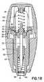
たとえば、図19は、本発明の代替実施形態におけるランセット装置10aの断面図を示す。この実施形態において、押しボタン25a等の作動要素を含むアクチュエータによって作動が達成される。特に、ハウジング12aが、本体20aおよび後部キャップ24aによって画定されている。押しボタン25aは、後部キャップ24aにおいてハウジング12aを通りその内部の内部空洞28a内に延在している。押しボタン25aをハウジング12a内に軸方向に移動させ、それによって、ハウジング12a内の押しボタン25aの前端部にある1つまたは複数の係合面47aが、レバー要素92aの対応する接触面96aに接触し、それによってレバー要素92aがピボットヒンジ98aの周囲で枢動することによって、ランセット装置10aの作動が達成される。上述した実施形態におけるように、こうした接触および枢動により、キャリア要素76aの支持面83aとレバー要素92aの肩部94aとの間の締まり嵌め係合が解除され、それにより、駆動ばね102aがハウジング12aを通してランセット72aを穿刺位置に押し進めることができる。押しボタン25a内の位置合せナブ104aによって、駆動ばね102aをキャリア要素76aと押しボタン25aとの間に維持することができる。別法として、キャリア要素とハウジングの後端部との間に駆動ばねを維持し、押しボタン要素がハウジングを通って延在して枢動作動を引き起こすことができる。  For example, FIG. 19 shows a cross-sectional view of a lancet device 10a in an alternative embodiment of the present invention. In this embodiment, actuation is achieved by an actuator that includes an actuation element such as a push button 25a. In particular,housing 12a is defined bybody 20a andrear cap 24a. The push button 25a extends through thehousing 12a at therear cap 24a and into an internal cavity 28a therein. The push button 25a is moved axially into thehousing 12a so that one ormore engagement surfaces 47a at the front end of the push button 25a in thehousing 12a are brought into contact with acorresponding contact surface 96a of the lever element 92a. Actuation of the lancet device 10a is achieved by contact and thereby pivotal movement of the lever element 92a about thepivot hinge 98a. As in the embodiment described above, such contact and pivot release the interference fit between thesupport surface 83a of the carrier element 76a and the shoulder 94a of the lever element 92a so that thedrive spring 102a The lancet 72a can be pushed to the puncturing position through 12a.Alignment nub 104a in push button 25a allowsdrive spring 102a to be maintained between carrier element 76a and push button 25a. Alternatively, a drive spring may be maintained between the carrier element and the rear end of the housing, with the pushbutton element extending through the housing to cause pivoting movement.

図17に示すような作動に戻ると、駆動ばね102の付勢力により、ランセット構造体70がシールド本体50を通して穿刺位置まで押し進められ、穿刺位置では、ランセット72の穿刺端部74は、穿刺端部74が皮膚表面Sを穿刺するのを可能にするのに十分な距離にわたり、前端壁58を通る前方開口部60を通って延在する。シールド本体50内の案内チャネル80の底面81は、このように押し進められる間、ランセット構造体70が前方開口部60を通ってシールド本体50から出るように完全に軸方向に移動するのを防止するように、案内タブ78に対する当接面を提供する。さらに、このように押し進められる間、キャリア要素76の前面88が、引戻しばね110の後端部と接触し、引戻しばね110は、シールド本体50の前端部52内に、望ましくはランセット装置の作動前状態および/または作動可能状態における弛緩された状態に保持される。駆動ばね102の付勢からの推進力により、引戻しばね110とのこうした接触がもたらされ、それにより、引戻しばね110を、ランセット構造体70の前面88とシールド本体50の前端壁58の内部との間で圧縮する。引戻しばね110の構造は、ランセット構造体70を押し進める駆動ばね102の付勢力に基づいて、ランセット72の穿刺端部74が前方開口部60を通って延在するのを可能にするように圧縮可能であるように設計される。さらに、引戻しばね110は圧縮ばねであり、したがって、このように圧縮されることが可能であるが、ランセット構造体70が穿刺位置まで伸長した後に弛緩状態に戻るのに十分な弾性を有する。したがって、駆動ばね102がランセット構造体70を穿刺位置に駆動した後、弛緩状態にあるときのシールド本体50の前端壁58とランセット構造体70との間の圧縮ばね110の付勢力は、ハウジング12の後部キャップ24とランセット構造体70の後部ナブ86との間に作用する駆動ばね102の付勢力を超える。このように、引戻しばね110は、非圧縮状態まで弛緩し、したがって、ランセット構造体70の前面88と前端壁58の内面との間に付勢力を加え、それによって、ランセット構造体70を後部キャップ24に向かって後方に押す。こうした付勢力が、ランセット72の穿刺端部74が前方開口部60を通して露出することから遮蔽される位置まで、シールド本体50内にランセット72の穿刺端部74を後退させる。さらに、駆動ばね102と引戻しばね110との間に作用する対向する力、およびそれらの構造に基づいたこうしたばねのそれぞれの力により、穿刺端部74がシールド本体50内に遮蔽された状態でランセット構造体70がハウジング12内に配置されて保持され、ランセット構造体70が穿刺位置までさらに移動するのが防止される。  Returning to the operation as shown in FIG. 17, the biasing force of thedrive spring 102 pushes thelancet structure 70 through theshield body 50 to the puncturing position. In the puncturing position, the puncturingend 74 of thelancet 72 becomes the puncturing end. 74 extends through thefront opening 60 through thefront end wall 58 for a distance sufficient to allow the puncture of the skin surface S. Thebottom surface 81 of theguide channel 80 in theshield body 50 prevents thelancet structure 70 from moving completely axially out of theshield body 50 through thefront opening 60 during such pushing. As such, an abutment surface for theguide tab 78 is provided. In addition, during such a push, thefront face 88 of thecarrier element 76 contacts the rear end of theretraction spring 110, which is located in thefront end 52 of theshield body 50, preferably prior to activation of the lancet device. The state and / or the relaxed state in the ready state is maintained. Propulsion from the bias of thedrive spring 102 causes such contact with theretraction spring 110, thereby causing theretraction spring 110 to move between thefront face 88 of thelancet structure 70 and the interior of thefront end wall 58 of theshield body 50. Compress between. The structure of theretraction spring 110 is compressible to allow the piercingend 74 of thelancet 72 to extend through thefront opening 60 based on the biasing force of thedrive spring 102 pushing thelancet structure 70. Designed to be. Further, theretraction spring 110 is a compression spring, and thus can be compressed in this way, but has sufficient elasticity to return to the relaxed state after thelancet structure 70 has been extended to the puncture position. Therefore, after thedrive spring 102 drives thelancet structure 70 to the puncturing position, the urging force of thecompression spring 110 between thefront end wall 58 of the shieldmain body 50 and thelancet structure 70 in the relaxed state is reduced by thehousing 12. Over the biasing force of thedrive spring 102 acting between therear cap 24 and therear nub 86 of thelancet structure 70. In this manner, theretraction spring 110 relaxes to an uncompressed state, thus exerting a biasing force between thefront surface 88 of thelancet structure 70 and the inner surface of thefront end wall 58, thereby causing thelancet structure 70 to Push backwards towards 24. Such biasing force retracts thepuncture end 74 of thelancet 72 into theshield body 50 to a position where thepuncture end 74 of thelancet 72 is shielded from being exposed through thefront opening 60. Further, the opposing forces acting between thedrive spring 102 and theretraction spring 110, and the respective forces of such springs based on their structure, allow thelancet 74 to be lanced with the piercingend 74 shielded within theshield body 50. Thestructure 70 is disposed and held within thehousing 12 to prevent thelancet structure 70 from further moving to the puncturing position.

さらに、ランセット装置の起動後、すなわち、穿刺位置の後にランセット構造体70がハウジング12内に後退した後、シールド本体50およびハウジング12を固定関係でロックすることができる。特に、シールド本体50が後部キャップ24に向かって軸方向に変位すると、ロックフィンガ59が偏向して、それぞれの凹部29内でロックし、それによって、シールド本体50が後部キャップ24およびハウジング12に対して後方位置でロックされ得る。したがって、ランセット装置10は、再使用されないように安全に保護され、適切な医療用ごみ容器内等に適切に廃棄され得る。  Further, after the lancet device is activated, that is, after thelancet structure 70 is retracted into thehousing 12 after the puncturing position, theshield body 50 and thehousing 12 can be locked in a fixed relationship. In particular, when theshield body 50 is axially displaced toward therear cap 24, the lockingfingers 59 deflect and lock within therespective recesses 29, thereby causing theshield body 50 to move relative to therear cap 24 and thehousing 12. And can be locked in the rearward position. Therefore, thelancet device 10 is safely protected from being reused, and can be properly disposed of in a suitable medical waste container or the like.

図20〜図22を参照すると、ランセット装置は、変更版の保持ハブ90iを含むことができる。図20は、保持ハブ90iを上述したようなランセット装置10の一部として示し、図20〜図22に示す同様の参照番号は図1〜図18と関連して説明した同様の要素を指す。保持ハブ90iは、概して、環状形状を画定し、ランセット構造体70を、本体20および後部キャップ24によって画定されるハウジング内に後退した初期作動可能位置に維持するように適合される。保持ハブ90iは、典型的には、2つの枢動するカム要素92iによって接続された2つの対向する細長い支持部材91iを含み、保持ハブ90iの環状形状を形成する。カム要素92iは各々、対向する支持部材91iと枢動可能に係合する2つの外側に延在するシャフト93iを含む。カム要素92iは各々、上面に上部接触面96iを画定する、少なくとも1つの典型的には楔形状の接触要素94iをさらに含む。カム要素92iは各々、底部側に画定された、概して中央に配置された凹部または切取り部100iをさらに画定する。凹部100iの目的について、本明細書では、ランセット装置10における保持ハブ90iの動作に関連して説明する。図21Aおよび図22に示すように、カム要素92iは、望ましくは、各々、カム要素92iの概して両端に配置された2つの接触要素94iを含み、凹部100iは、接触要素94i間のカム要素92iの底部側に画定される。  Referring to FIGS. 20-22, the lancet device may include a modified version of the holding hub 90i. FIG. 20 shows the holding hub 90i as part of thelancet device 10 as described above, and like reference numbers shown in FIGS. 20 to 22 refer to like elements described in connection with FIGS. Retention hub 90i defines a generally annular shape and is adapted to maintainlancet structure 70 in a retracted, initial, operable position within a housing defined bybody 20 andrear cap 24. Retention hub 90i typically includes two opposing elongated support members 91i connected by two pivoting cam elements 92i to form an annular shape of retention hub 90i. The cam elements 92i each include two outwardly extendingshafts 93i that pivotally engage with opposing support members 91i. The cam elements 92i each further include at least one typically wedge-shapedcontact element 94i that defines an upper contact surface 96i on a top surface. The cam elements 92i each further define a generally centrally located recess orcutout 100i defined on the bottom side. The purpose of therecess 100i will be described herein in connection with the operation of the holding hub 90i in thelancet device 10. As shown in FIGS. 21A and 22, the cam elements 92i desirably include twocontact elements 94i, each disposed generally at either end of the cam element 92i, and therecess 100i is provided between thecontact elements 94i. Is defined on the bottom side.

この実施形態のランセット装置では、保持ハブ90iおよびランセット構造体70は互いに締まり嵌め係合しており、それにより、保持ハブ90iは、ランセット構造体70を、ハウジング内に後退した初期作動可能状態で保持する。たとえば、キャリア要素76のフィンガ82は、カム要素92iの上部側に載置されることができ、それによりランセット構造体70と保持ハブ90iとの間に締まり嵌め係合をもたらす。さらに、接触要素94iの上部接触面96iは、ハウジング内の構造体と接触係合するように適合され得る。たとえば、後部キャップ24は、一体形成されかつその少なくとも1つ、望ましくは2つの対向する内部側壁に延在する内部接触部46等、内部に延在する構造体を含むことができる。保持ハブ90iは、典型的には、各カム要素92iに2つの接触要素94iを含むため、ハウジングの2つの対向する内部側壁の各々に、上述した接触部46のような2つの内部接触部を設けることができる。各内部接触部は、接触要素94iの対応する接触面96iと接触係合する上述したカム面47等の先端側係合カム面を含む。  In the lancet device of this embodiment, the retaining hub 90i and thelancet structure 70 are in an interference fit with each other, such that the retaining hub 90i moves thelancet structure 70 back into the housing in an initially operable condition. Hold. For example, thefingers 82 of thecarrier element 76 can rest on the upper side of the cam element 92i, thereby providing an interference fit between thelancet structure 70 and the holding hub 90i. Further, the upper contact surface 96i of thecontact element 94i may be adapted to contact and engage a structure within the housing. For example, therear cap 24 can include an internally extending structure, such as aninner contact 46 that is integrally formed and extends to at least one, and preferably two, opposing inner sidewalls thereof. The retaining hub 90i typically includes twocontact elements 94i on each cam element 92i, so that each of the two opposing internal side walls of the housing has two internal contacts, such ascontact 46 described above. Can be provided. Each internal contact portion includes a distal engagement cam surface, such as thecam surface 47 described above, in contact engagement with a corresponding contact surface 96i of thecontact element 94i.

図20〜図22のランセット装置の通常の動作中、後部キャップ24に向かうシールド本体50の軸方向または長手方向の移動により、キャリア要素76のフィンガ82がカム要素92i上に載置された状態で、保持ハブ90iが後部キャップ24に向かって後方に変位する。保持ハブ90iのこうした後方移動により、後部キャップ24内の内部接触部の係合カム面の接触面が、カム要素92iの接触要素94i上の対応する接触面96iと係合しかつそれと協働する。内部接触部がこのように係合し、引き続き下方または先端側に移動することにより、カム要素92iが、支持部材91iに対してシャフト93i上で枢動するか、またはシャフト93iの周囲を回転する。接触要素94iが概して楔形状の輪郭であるため、カム要素92iの枢動は、少なくともキャリア要素76の後部ナブ86が後部キャップ24の内側に接触する箇所まで、フィンガ82をさらに「持ち上げること」によって駆動ばね102をさらに圧縮する効果を有する。この時点で、シールド本体50を後部キャップ24に向かって軸方向または長手方向に移動し続けることにより、カム要素92iは、カム要素92iの底部側に画定された凹部100iがフィンガ82と概して位置合せされた位置まで回転し、その時点で、フィンガ82とカム要素92iとの間の締まり嵌め係合がこうした位置合せにより解除される位置まで枢動される。次に、駆動ばね102の付勢力により、ランセット構造体70が、後部キャップ24から離れるように、ハウジングを通して軸方向に、かつ保持ハブ90iによって画定される環状開口部を通して軸方向にシールド本体50を通して、下方に押し進められる。  During normal operation of the lancet device of FIGS. 20-22, axial or longitudinal movement of theshield body 50 toward therear cap 24 causes thefinger 82 of thecarrier element 76 to rest on the cam element 92i. The holding hub 90i is displaced rearward toward therear cap 24. This rearward movement of the retaining hub 90i causes the contact surface of the engaging cam surface of the internal contact in therear cap 24 to engage and cooperate with a corresponding contact surface 96i on thecontact element 94i of the cam element 92i. . This engagement and subsequent downward or distal movement of the internal contact causes the cam element 92i to pivot on or rotate about theshaft 93i relative to the support member 91i. . Because thecontact element 94i has a generally wedge-shaped profile, the pivoting of the cam element 92i is achieved by further "lifting" thefinger 82 at least to the point where therear nub 86 of thecarrier element 76 contacts the inside of therear cap 24. This has the effect of further compressing thedrive spring 102. At this point, by continuing to move theshield body 50 axially or longitudinally toward therear cap 24, the cam element 92i causes therecess 100i defined on the bottom side of the cam element 92i to generally align with thefinger 82. At which time the interference fit between thefinger 82 and the cam element 92i is pivoted to a position where such alignment disengages. The biasing force of thedrive spring 102 then causes thelancet structure 70 to move axially through the housing away from therear cap 24 and through theshield body 50 axially through the annular opening defined by the holding hub 90i. , Pushed down.

図23A〜図23Dを参照すると、さらなる実施形態において、ランセット装置のさらなる変形形態または変更形態が概して示されている。図23A〜図23Dの実施形態では、ランセット装置200の形態の穿刺装置が示されている。ランセット装置200は、概して、ハウジング211と、ハウジング211内に部分的に受け入れられかつハウジング211に対して軸方向に移動可能なシールド213と、ハウジング211内に配置された(上述したランセット構造体70と同様であり得る)皮膚穿刺アセンブリ215とを含む。ハウジング211は、好ましくは、先端部216および基端部218を有する概して管状の構造体であり、本体20および後部キャップ24を含む、図1〜図18に関連して上述したハウジング12と同様の構造体を含むことができる。望ましくは、ハウジング211は、先端部216および基端部218において端部が開放している。ハウジング211の基端部218を閉鎖するように、ハウジング211の基端部218にエンドキャップ240を設けることができる。別法として、ハウジング211は、エンドキャップ240の代わりに閉鎖した基端部218を有するように形成することができる。こうした実施形態において、ハウジング211の閉鎖した基端部218は、穿刺装置200のこの変形形態におけるハウジング211の本体の残りの部分と一体形成される。皮膚穿刺アセンブリ215は、キャリア部材250に接続された保護チップガード282をさらに含むことができる。チップガード282は、キャリア部材250の本体と一体形成することができ、上述した保護カバー120と同様にキャリア部材250との切欠き接続部を含むことができる。  With reference to FIGS. 23A-23D, in a further embodiment, further variations or modifications of the lancet device are generally shown. 23A to 23D, a lancing device in the form of alancet device 200 is shown. Thelancet device 200 generally includes ahousing 211, ashield 213 partially received within thehousing 211 and axially movable with respect to thehousing 211, and disposed within the housing 211 (thelancet structure 70 described above). Skin piercing assembly 215).Housing 211 is preferably a generally tubular structure having adistal end 216 and aproximal end 218, similar tohousing 12 described above in connection with FIGS. 1-18, including abody 20 and arear cap 24. Structures can be included. Desirably,housing 211 has open ends atdistal end 216 andproximal end 218. Anend cap 240 may be provided on theproximal end 218 of thehousing 211 to close theproximal end 218 of thehousing 211. Alternatively, thehousing 211 can be formed to have a closedproximal end 218 instead of theend cap 240. In such an embodiment, the closedproximal end 218 of thehousing 211 is integrally formed with the remainder of the body of thehousing 211 in this variation of thepuncture device 200.Skin puncture assembly 215 may further include aprotective tip guard 282 connected tocarrier member 250. Thetip guard 282 can be formed integrally with the main body of thecarrier member 250, and can include a notch connection with thecarrier member 250, similarly to theprotective cover 120 described above.

シールド213の基端部244上に撓み部材238が形成されるか、または設けられる。撓み部材238は、図1〜図18と関連して上述した実施形態の枢支レバー要素および保持ハブと同様に作用する、ランセット構造体をハウジング内に後退した初期作動可能位置に保持するための構造を画定する。たとえば、撓み部材238の突起部276は、皮膚穿刺アセンブリ215のキャリア部材250と係合または協働するように内側に延在する。突起部276は、キャリア部材250に画定されたまたは形成された周方向凹部210に係合するか、またはその中に延在する。この凹部210は、撓み部材238の突起部276が係合する周方向縁部212を画定する。図23A〜図23Dに示すランセット装置200の突起部276の係合縁部277は、突起部276の各々の半径方向内側に延在するタブ214によって形成または画定される。係合縁部277は、図1〜図18を参照して上述した肩部94と同様の方法で作用し、荷重は、係合縁部277に載置されている皮膚穿刺アセンブリ215によって表される。  Aflexible member 238 is formed or provided on theproximal end 244 of theshield 213. Theflexure member 238 acts similarly to the pivot lever element and retention hub of the embodiment described above in connection with FIGS. 1-18 for retaining the lancet structure in the retracted initial ready position within the housing. Define the structure. For example,protrusion 276 offlexure member 238 extends inwardly to engage or cooperate withcarrier member 250 ofskin piercing assembly 215.Protrusion 276 engages or extends intocircumferential recess 210 defined or formed incarrier member 250. Therecess 210 defines acircumferential edge 212 with which theprotrusion 276 of theflexure 238 engages. Theengagement edge 277 of theprojection 276 of thelancet device 200 shown in FIGS. 23A-23D is formed or defined by atab 214 extending radially inward of each of theprojections 276.Engagement edge 277 acts in a similar manner to shoulder 94 described above with reference to FIGS. 1-18, and the load is represented byskin piercing assembly 215 resting onengagement edge 277. You.

突起部276は、ハウジング211内へのシールド213の軸方向変位によってキャリア部材250との係合が解除されるまで、キャリア部材250、したがって皮膚穿刺アセンブリ215を後退位置に維持する。ランセット装置200の作動前状態において、駆動ばね270の付勢力は、突起部276によって、かつハウジング211の先端部216に設けられた締まり嵌め構造体とのシールド213の先端部242の係合によって抑制される。特に、シールド213はハウジング211内に軸方向または長手方向に移動可能または変位可能であるが、シールド213は、シールド213に形成された縁部217によって、ハウジング211に対して先端側に移動することが防止される。縁部217は、増大した壁厚を有するシールド213の部分219によって形成されるか、または画定される。縁部217は、ハウジング211の先端部216に形成された内部リップ220と協働または係合して、駆動ばね270の力を抑制する。リップ220との縁部217の係合により、撓み部材238がキャリア部材250を後退位置に維持し、駆動ばね270の力を抑制することができる。特に、ランセット装置200の作動前状態において、駆動ばね270の力は、突起部276を介してシールド213の本体に伝達され、それによって、シールド213の縁部217がリップ220と係合し、駆動ばね270の力を抑制する。  Theprotrusion 276 maintains thecarrier member 250, and thus theskin piercing assembly 215, in the retracted position until the axial displacement of theshield 213 into thehousing 211 disengages thecarrier member 250. In a state before the operation of thelancet device 200, the urging force of thedrive spring 270 is suppressed by theprojection 276 and the engagement of thedistal end 242 of theshield 213 with the interference fitting structure provided on thedistal end 216 of thehousing 211. Is done. In particular, theshield 213 can be moved or displaced in the axial direction or the longitudinal direction within thehousing 211, but theshield 213 is moved to the distal end side with respect to thehousing 211 by theedge 217 formed on theshield 213. Is prevented.Edge 217 is formed or defined by aportion 219 ofshield 213 having an increased wall thickness. Theedge 217 cooperates or engages with aninternal lip 220 formed at thedistal end 216 of thehousing 211 to constrain the force of thedrive spring 270. The engagement of theedge 217 with thelip 220 allows theflexure member 238 to maintain thecarrier member 250 in the retracted position and reduce the force of thedrive spring 270. In particular, before the operation of thelancet device 200, the force of thedrive spring 270 is transmitted to the main body of theshield 213 via theprotrusion 276, whereby theedge 217 of theshield 213 engages with thelip 220, The force of thespring 270 is suppressed.

撓み部材238は、(図1〜図18を参照して上述した実施形態における内部接触部46と同様の)1つまたは複数の作動部材222によって、キャリア部材250との係合が解除されるように適合される。作動部材222は、エンドキャップ240と一体形成することができ、またはエンドキャップ240とは別個に形成し、たとえば、接着剤を用いてエンドキャップ240に固定することができる。作動部材222は、穿刺装置200を作動させるために、撓み部材238のテーパ状カム面278と協働または係合するように適合された、(係合面47と同様の)テーパ状カム面224を含む。特に、図23A〜図23Dに示す穿刺装置200を作動させるために、使用者、典型的には医師は、シールド213の先端部242を、血液サンプルが採取されるべき身体部分と接触させて配置し、図23A〜図23Dの矢印226の方向に圧力を加えて、シールド213をハウジング211内に基端側に移動させる。ハウジング211内へのシールド213の移動により、撓み部材238および作動部材222上の対向するカム面278、224がそれぞれ係合しかつ相互作用する。図23Cおよび図23Dに示すように、シールド213がハウジング211内に変位または移動するに従い、対向するカム面278、224の相互作用のために、撓み部材238が半径方向外側に撓む。撓み部材238は、所定の距離、回転角度、または量だけ半径方向外側に撓むと、曲がるかまたは破断するように適合または構成され得る。たとえば、撓み部材238は、切込み線等の脆弱領域228を有するように形成され、それにより、撓み部材238は、所定の距離または所定の程度の回転だけ半径方向外側に撓むと破断する。さらに、脆弱領域228は、上述したピボットヒンジ98と同様にヒンジとして作用することができる。  Theflexure member 238 is disengaged from thecarrier member 250 by one or more actuation members 222 (similar to theinternal contact portion 46 in the embodiment described above with reference to FIGS. 1-18). Is adapted to. The actuatingmember 222 can be integrally formed with theend cap 240 or can be formed separately from theend cap 240 and secured to theend cap 240 using, for example, an adhesive. The actuatingmember 222 includes a tapered cam surface 224 (similar to the engagement surface 47) adapted to cooperate or engage with the taperedcam surface 278 of theflexible member 238 to operate the lancingdevice 200. including. In particular, to operate the lancingdevice 200 shown in FIGS. 23A-23D, a user, typically a physician, places thetip 242 of theshield 213 in contact with the body part where a blood sample is to be taken. Then, pressure is applied in the direction of thearrow 226 in FIGS. 23A to 23D to move theshield 213 into thehousing 211 in the proximal direction. Movement ofshield 213 intohousing 211 causes opposing cam surfaces 278, 224 onflexure member 238 andactuation member 222 to engage and interact, respectively. As shown in FIGS. 23C and 23D, asshield 213 is displaced or moved intohousing 211,flexure member 238 flexes radially outward due to the interaction of opposing cam surfaces 278,224.Flexure member 238 may be adapted or configured to flex or break when flexing radially outward a predetermined distance, rotation angle, or amount. For example, theflexure member 238 is formed to have a weakenedarea 228, such as a score line, such that theflexure member 238 breaks when flexing radially outward a predetermined distance or a predetermined degree of rotation. Further, the weakenedarea 228 can act as a hinge, similar to thepivot hinge 98 described above.

撓み部材238のこうした移動中、突起部276は、後部エンドキャップ240に向かって傾斜し、それにより、キャリア部材250を後部エンドキャップ240に向かって「持ち上げ」または移動させ、駆動ばね270を圧縮するかまたはさらに圧縮する。撓み部材238上の突起部276がキャリア部材250との係合から解除されると、駆動ばね270は、キャリア部材250を後退位置から穿刺位置まで自由に移動させることができる。撓み部材238がキャリア部材250との係合から解除されると、駆動ばね270は、好ましくは、皮膚穿刺要素215の鋭利な先端チップ254が人または動物の皮膚を穿刺するのに十分に蓄積されたエネルギーを有する。  During such movement of theflexure member 238, theprotrusion 276 tilts toward therear end cap 240, thereby “lifting” or moving thecarrier member 250 toward therear end cap 240 and compressing thedrive spring 270. Or further compress. When theprotrusion 276 on theflexible member 238 is released from engagement with thecarrier member 250, thedrive spring 270 can move thecarrier member 250 freely from the retracted position to the puncturing position. When theflexure member 238 is disengaged from thecarrier member 250, thedrive spring 270 preferably accumulates enough for thesharp tip 254 of theskin piercing element 215 to pierce the skin of a human or animal. Energy.

キャリア部材250が先端側に移動し、皮膚穿刺要素215の鋭利な先端チップ254が完全に露出する穿刺位置に達すると、図1〜図18を参照して上述した引戻しばね110と同様に、引戻しばね274が、キャリア部材250とシールド213の先端部242との間で圧縮される。引戻しばね274の圧縮により、キャリア部材250に作用してハウジング211においてキャリア部材250を戻り方向、基端方向、または後退方向に移動させる戻し力または引戻し力がもたらされ、それにより、皮膚穿刺要素215およびその鋭利な先端チップ254がハウジング211およびシールド213内に完全に戻るかまたは後退する。その後、引戻しばね274は、ハウジング211およびシールド213からの皮膚穿刺要素215の再出現を防止する。  When thecarrier member 250 moves distally and reaches a puncturing position where the sharpdistal tip 254 of theskin piercing element 215 is completely exposed, similar to theretraction spring 110 described above with reference to FIGS. Aspring 274 is compressed between thecarrier member 250 and thetip 242 of theshield 213. The compression of theretraction spring 274 provides a retraction or retraction force that acts on thecarrier member 250 to move thecarrier member 250 in the return, proximal, or retract directions in thehousing 211, thereby causing the skin-piercingelement 215 and itssharp tip 254 return or retract completely withinhousing 211 andshield 213. Thereafter, theretraction spring 274 prevents the re-emergence of theskin piercing element 215 from thehousing 211 and theshield 213.

図24および図25は、本開示のウィッキング材料およびランセット装置の例示的な実施形態を示す。本開示のこの実施形態は、患者から血液サンプルを得るために患者の皮膚を穿刺する、医療分野において使用されるランセット装置10Bおよびウィッキング材料300である。ランセット装置10Bは、ランセット装置10Bの一部として、血液の第1液滴の除去を補助するウィッキング材料300を含み、それにより、血液検査結果がより正確なものとなるように患者が第1液滴除プロセスに従うのに役立つ効率的な装置を提供する。図24および図25に示すランセット装置10Bは、図1〜図23Dに示すランセット装置10と同様の構成要素を含み、同様の構成要素は、ランセット装置10に関して上述したものと同じ参照番号によって示す。明確にするために、これらの同様の構成要素とランセット装置10B(図24および図25)を用いる同様のステップとについては、図24および図25に示す実施形態とともにすべては考察しない。図24〜図34の例示的な実施形態は、図1〜図23Dに示すランセット装置10と同様の構成要素を含むように示されているが、本開示のウィッキング材料システムは、患者から血液サンプルを得るために患者の皮膚を穿刺する任意のランセット装置で利用することができる。  24 and 25 illustrate exemplary embodiments of the wicking material and lancet device of the present disclosure. This embodiment of the present disclosure is alancet device 10B andwicking material 300 used in the medical field to puncture a patient's skin to obtain a blood sample from the patient. Thelancet device 10B includes, as part of thelancet device 10B, awicking material 300 that assists in the removal of the first drop of blood, thereby allowing the patient to perform the first test so that the blood test results are more accurate. Provide an efficient device that helps to follow the droplet removal process. Thelancet device 10B shown in FIGS. 24 and 25 includes components similar to those of thelancet device 10 shown in FIGS. 1 to 23D, and similar components are denoted by the same reference numerals as described above with respect to thelancet device 10. For the sake of clarity, these similar components and similar steps using thelancet device 10B (FIGS. 24 and 25) will not be considered at all with the embodiment shown in FIGS. Although the exemplary embodiment of FIGS. 24-34 is shown to include components similar to thelancet device 10 shown in FIGS. 1-23D, the wicking material system of the present disclosure provides It can be used with any lancet device that pierces the patient's skin to obtain a sample.

本開示のウィッキング材料300は、患者の皮膚Sから血液の第1液滴を吸収し吸い取ることが重要である。いくつかの実施形態では、血糖のセルフモニタリングが糖尿病治療の重要な部分である。患者は、食事、運動および薬剤に関して適切な判断を行うことができるように、患者の体内の血糖濃度を適時にかつ確実に評価するために血液サンプルを得る必要がある。患者が、除去される血液の第1液滴から血液サンプルを得て、自らの手を適切に洗浄しない場合、採取された血液サンプルの完全性に著しい誤差がもたらされる可能性がある。手洗いが行われない場合、検査されている血液の第2液滴は、血糖値に対して検査されている血液の第1液滴より正確であることが分かった。さらに、血液サンプルを採取する前に患者が果物等の食物を扱う状況では、果物からの過剰な糖分のために血液検査が不正確になる可能性がある。過剰な糖分を有する食物を扱うとき、検査されている血液の第2液滴は、血糖値に対して検査されている血液の第1液滴より正確であることが分かった。これらの理由で、本開示のランセット装置は、血液検査結果をより正確なものとするように患者が第1液滴除去プロセスに従うのに役立つ効率的な装置を提供する。  It is important that thewicking material 300 of the present disclosure absorb and absorb the first drop of blood from the patient's skin S. In some embodiments, self-monitoring of blood glucose is an important part of treating diabetes. Patients need to obtain blood samples in a timely and reliable manner to assess their blood glucose levels so that they can make appropriate decisions regarding diet, exercise and medication. If the patient obtains a blood sample from the first drop of blood to be removed and does not properly wash his or her hands, it can result in significant errors in the integrity of the collected blood sample. If hand washing was not performed, the second drop of blood being tested was found to be more accurate for blood glucose levels than the first drop of blood being tested. Further, in situations where a patient handles food such as fruits before taking a blood sample, blood tests can be inaccurate due to excessive sugar from the fruits. When dealing with food with excess sugar, the second drop of blood being tested was found to be more accurate for blood glucose levels than the first drop of blood being tested. For these reasons, the lancet device of the present disclosure provides an efficient device that helps the patient follow the first drop removal process to make blood test results more accurate.

一実施形態では、ウィッキング材料300は、ランセット構造体70の起動時に形成されたランセット傷から引き出される第1量の血液を吸収することができる材料から作製される。たとえば、ウィッキング材料300は、コットンガーゼ、ウィッキング紙、プレス紙材料、吸収繊維、およびウィッキング特性を有するさまざまなプラスチック等のさまざまな吸収材料から形成することができる。ウィッキング材料300を作製するために使用される材料の重要な特性は、ランセット構造体70の起動時に形成されたランセット傷から引き出される第1量の血液を吸収し得ることである。一実施形態では、ウィッキング材料300はまた、より詳細に後述するように、ランセット構造体70の穿刺端部74によって穿刺されることが可能な材料から作製される。  In one embodiment, the wickingmaterial 300 is made from a material capable of absorbing a first amount of blood drawn from a lancet wound formed upon activation of thelancet structure 70. For example, the wickingmaterial 300 can be formed from various absorbent materials, such as cotton gauze, wicking paper, pressed paper material, absorbent fibers, and various plastics having wicking properties. An important property of the material used to make thewicking material 300 is that it can absorb a first amount of blood drawn from a lancet wound formed upon activation of thelancet structure 70. In one embodiment, the wickingmaterial 300 is also made from a material that can be pierced by the piercingend 74 of thelancet structure 70, as described in more detail below.

図3および図24を参照すると、一実施形態では、シールド14は、ハウジング12の前端部を通って開口部30から外側に延在している。シールド14は、前端部52と後端部54との間に延在するシールド本体50を画定し、内部を通して延在する内部空洞56を画定する、概して円筒状の中空構造体である。シールド本体50の前端部52は、貫通する前方開口部60を含む前端壁58を画定し、使用者がランセット装置10を作動させると、穿刺要素がそこを通って延在する。前端壁58は、概して、先端開口部60の周囲に、穿刺要素によって穿刺されるべき使用者の身体の意図された部位と接触する小さい接触領域を画定する。シールド14に形成される複数の周縁陥凹部62を設けることによって、縮小された接触領域をより小さく、すなわち面積を縮小することができる。周縁陥凹部62はまた、使用者が、概してランセット装置10の照準を定め、特にランセットの穿刺要素の照準を定める際に視覚的に補助するターゲット指標も提供することができる。周縁陥凹部62は、概して、ハウジング12に設けられた周縁陥凹部42に類似している。周縁陥凹部42は、シールド14の外周部に配置され、シールド14の周囲に等しく間隔を空けて配置され得る。周縁陥凹部42により、使用者は、穿刺要素のおよその吐出点の位置を容易に視覚的に特定することができ、それにより、ランセット装置10の照準特性が改善され、皮膚穿刺操作中に最適な血流が確保される。  Referring to FIGS. 3 and 24, in one embodiment, theshield 14 extends outwardly from theopening 30 through the front end of thehousing 12. Theshield 14 is a generally cylindrical hollow structure defining ashield body 50 extending between afront end 52 and arear end 54 and defining aninternal cavity 56 extending therethrough. Thefront end 52 of theshield body 50 defines afront end wall 58 that includes afront opening 60 therethrough, through which the piercing element extends when the user activates thelancet device 10. Thefront end wall 58 generally defines a small contact area around the tip opening 60 that contacts the intended site of the user's body to be punctured by the piercing element. By providing the plurality ofperipheral recesses 62 formed in theshield 14, the reduced contact area can be made smaller, that is, the area can be reduced. Theperipheral recess 62 can also provide a target indicator that visually assists the user in aiming thelancet device 10 in general, and particularly in aiming the puncturing element of the lancet.Peripheral recess 62 is generally similar toperipheral recess 42 provided inhousing 12.Peripheral recesses 42 are located on the outer periphery ofshield 14 and may be equally spaced aroundshield 14. Theperipheral recess 42 allows the user to easily and visually locate the approximate point of ejection of the lancing element, thereby improving the aiming characteristics of thelancet device 10 and making it optimal during a skin lancing operation. Blood flow is secured.

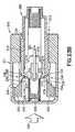
図24を参照すると、ランセット装置10Bは、シールド本体50の前端壁58等において、ランセット構造体70の開口部60の内部に配置されたウィッキング材料300を含む。ウィッキング材料300は、シールド本体50の前端壁58において開口部60内に固定可能であり、すなわち、ウィッキング材料300は、ランセット装置10Bの起動時にランセット傷から引き出される第1量の血液を吸収することができるように、シールド本体50の前端壁58の開口部60内に固定可能である。一実施形態では、シールド本体50の前端壁58の内壁61には、図24に示すように、シールド本体50の前端壁58において開口部60内にウィッキング材料300を取り付けるための接着剤がコーティングされている。このように、シールド本体50の前端壁58の内壁61に、ウィッキング材料300を押圧することができ、接着剤は、シールド本体50の前端壁58の内壁61にウィッキング材料300を取り付ける。他の実施形態では、シールド本体50の前端壁58の内壁61は、シールド本体50の前端壁58における開口部60内にウィッキング材料300を固定する他の接続機構を含むことができる。別の実施形態では、ウィッキング材料300をランセット構造体70の一部と同時に形成することができる。  With reference to FIG. 24, thelancet device 10B includes awicking material 300 disposed inside theopening 60 of thelancet structure 70, such as at thefront end wall 58 of theshield body 50. The wickingmaterial 300 is securable within theopening 60 at thefront end wall 58 of theshield body 50, ie, the wickingmaterial 300 absorbs a first amount of blood drawn from the lancet wound upon activation of thelancet device 10B. So that it can be fixed in theopening 60 of thefront end wall 58 of theshield body 50. In one embodiment, theinner wall 61 of thefront end wall 58 of theshield body 50 is coated with an adhesive to attach thewicking material 300 into theopening 60 at thefront end wall 58 of theshield body 50, as shown in FIG. Have been. In this manner, the wickingmaterial 300 can be pressed against theinner wall 61 of thefront end wall 58 of theshield body 50, and the adhesive attaches thewicking material 300 to theinner wall 61 of thefront end wall 58 of theshield body 50. In other embodiments, theinner wall 61 of thefront end wall 58 of theshield body 50 can include other connection features that secure thewicking material 300 within theopening 60 in thefront end wall 58 of theshield body 50. In another embodiment, the wickingmaterial 300 can be formed simultaneously with a portion of thelancet structure 70.

ランセット装置10Bの作動は、上述したものと同様に達成される。上述したように、使用時、ランセット構造体70は、作動前位置に維持され、すなわち、フィンガ82と肩部94との間の締まり嵌め係合のために、図24に示すように、ランセット構造体70の穿刺端部74は、シールド本体50およびハウジング12内に後退し遮蔽されて維持される。ランセット装置の作動中、ピボットヒンジ98を中心としてレバー要素92を枢動させることにより、肩部94が後部キャップ24の後端部に向かってさらに変位し、それにより、駆動ばね102をさらに圧縮しかつさらに付勢する。引き続きシールド本体50を後部キャップ24に向かって軸方向に変位させることにより、内部接触部46および接触面96の対応する面がさらに係合し、それにより、係合面47が、ロッド形状部分97の外周部でカム作用するか、またはその周囲に載置され、それによって、レバー要素92をさらに枢動させる。最終的に、こうした枢動により、図15および図16に示すように、肩部94とキャリア要素76のフィンガ82との間の締まり嵌め係合が解除される点まで肩部94が枢動する。この時点で、フィンガ82は肩部94から自由になり、環状リム100を貫通する内部開口部を通って軸方向に移動することができる。駆動ばね102の付勢力により、ランセット構造体70は、後部キャップ24から離れるように、ハウジング12およびシールド本体50ならびにウィッキング材料300を通って軸方向に下方に押し進められる。図25に示すように、ランセット構造体70の作動中、ランセット構造体70の穿刺端部74は、ウィッキング材料300を貫通し、患者から血液サンプルを得るように患者の皮膚Sを穿刺する。  The operation of thelancet device 10B is achieved in a manner similar to that described above. As described above, in use, thelancet structure 70 is maintained in the pre-actuated position, ie, because of the interference fit between thefinger 82 and theshoulder 94, as shown in FIG. Punctureend 74 ofbody 70 is retracted and shielded withinshield body 50 andhousing 12 and maintained. During operation of the lancet device, pivoting thelever element 92 about thepivot hinge 98 further displaces theshoulder 94 toward the rear end of therear cap 24, thereby further compressing thedrive spring 102. And further energize. Subsequent axial displacement of theshield body 50 toward therear cap 24 further engages the corresponding surfaces of theinner contact portion 46 and thecontact surface 96 such that theengagement surface 47 is Cammed or mounted around it, thereby further pivoting thelever element 92. Ultimately, such pivoting causes pivoting ofshoulder 94 to the point where the interference fit betweenshoulder 94 andfingers 82 ofcarrier element 76 is released, as shown in FIGS. . At this point, thefingers 82 are free from theshoulders 94 and can move axially through an internal opening through theannular rim 100. The biasing force of thedrive spring 102 urges thelancet structure 70 axially downward through thehousing 12 and theshield body 50 and thewicking material 300 away from therear cap 24. As shown in FIG. 25, during operation of thelancet structure 70, the piercingend 74 of thelancet structure 70 pierces thewicking material 300 and pierces the patient's skin S to obtain a blood sample from the patient.

図25を参照すると、ランセット構造体70の穿刺端部74が患者から血液サンプルを得るために患者の皮膚Sに穿刺している状態で、ウィッキング材料300は、ランセット構造体70の穿刺端部74によって穿刺される皮膚Sの部分と接触している。このように、ウィッキング材料300は、患者の皮膚Sから血液の第1液滴を自動的に吸収しかつ吸い取る。重要なことには、ランセット装置10Bにより、ウィッキング材料300が、いかなる追加のステップもなしに、患者の皮膚Sを穿刺するランセット装置10Bの通常動作中に、患者の皮膚Sから血液の第1液滴を自動的に吸収し吸い取ることができる。このように、本開示のランセット装置10Bは、血液検査結果をより正確なものとする第1液滴除去プロセスに患者が従うのに役立つ効率的な装置を提供する。  Referring to FIG. 25, with the piercingend 74 of thelancet structure 70 piercing the skin S of the patient to obtain a blood sample from the patient, the wickingmaterial 300 is applied to the piercing end of thelancet structure 70. 74 is in contact with the portion of skin S to be punctured. In this manner, the wickingmaterial 300 automatically absorbs and sucks the first drop of blood from the patient's skin S. Importantly, thelancet device 10B causes thewicking material 300 to cause a first drop of blood from the patient's skin S during normal operation of thelancet device 10B to puncture the patient's skin S without any additional steps. Droplets can be automatically absorbed and sucked. Thus, thelancet device 10B of the present disclosure provides an efficient device that helps the patient to follow the first drop removal process, which makes blood test results more accurate.

図26A、図26Bおよび図29A〜図30Bは、本開示のランセット装置の別の例示的な実施形態を示す。図1〜図23Dに示す実施形態と同様の本開示のこの実施形態は、患者から血液サンプルを得るために患者の皮膚を穿刺する、医療分野で使用されるランセット装置10Cである。ランセット装置10Cは、ランセット装置10Cの一部として、血液の第1液滴の除去を補助するウィッキング材料300Cを含み、それにより、血液検査結果がより正確なものとなるように患者が第1液滴除プロセスに従うのに役立つ効率的な装置を提供する。図26A、図26Bおよび図29A〜図30Bに示すランセット装置10Cは、図1〜図23Dに示すランセット装置10と同様の構成要素を含み、同様の構成要素は、ランセット装置10に関して上述したものと同じ参照番号によって示す。明確にするために、これらの同様の構成要素とランセット装置10C(図26A、図26Bおよび図29A〜図30B)を用いる同様のステップとについては、図26A、図26Bおよび図29A〜図30Bに示す実施形態とともにすべては考察しない。  26A, 26B and 29A-30B illustrate another exemplary embodiment of the lancet device of the present disclosure. This embodiment of the present disclosure, similar to the embodiment shown in FIGS. 1-23D, is a lancet device 10C used in the medical field to puncture a patient's skin to obtain a blood sample from the patient. The lancet device 10C includes, as part of the lancet device 10C, awicking material 300C that assists in the removal of the first drop of blood, thereby allowing the patient to perform the first blood test with more accurate blood test results. Provide an efficient device that helps to follow the droplet removal process. The lancet device 10C shown in FIGS. 26A, 26B, and 29A-30B includes the same components as thelancet device 10 shown in FIGS. 1-23D, wherein the similar components are the same as those described above for thelancet device 10. Indicated by the same reference number. For clarity, these similar components and similar steps using lancet device 10C (FIGS. 26A, 26B and 29A-30B) are described in FIGS. 26A, 26B and 29A-30B. Not all are discussed with the illustrated embodiments.

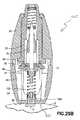
図26Aを参照すると、ランセット装置10Cは、後部キャップ24の最後部331内に凹部または空洞302を含む。一実施形態では、空洞302は、ウィッキング材料300Cを収容することができる。図26Aは、概して矩形状の空洞として空洞302を示すが、他の形状およびサイズの空洞302を用い得ることが企図される。空洞302は、ランセット構造体70の起動時に形成されたランセット傷から引き出される第1量の血液を吸収することができるウィッキング材料を格納することができる任意の形状およびサイズであり得る。別の実施形態では、後部キャップ24の最後部331は、ランセット構造体70の起動時に形成されたランセット傷から引き出される第1量の血液を吸収することができるウィッキング材料300Cから形成することができる。  Referring to FIG. 26A, the lancet device 10C includes a recess orcavity 302 in therearmost portion 331 of therear cap 24. In one embodiment,cavity 302 can containwicking material 300C. While FIG. 26A showscavity 302 as a generally rectangular cavity, it is contemplated that other shapes and sizes ofcavity 302 may be used. Thecavity 302 can be of any shape and size capable of storing a wicking material capable of absorbing a first amount of blood drawn from a lancet wound formed upon activation of thelancet structure 70. In another embodiment, therearmost portion 331 of therear cap 24 may be formed from awicking material 300C that can absorb a first amount of blood drawn from a lancet wound formed upon activation of thelancet structure 70. it can.

一実施形態では、空洞302は、ウィッキング材料300Cを収容することができる。上述したように、ウィッキング材料300Cは、ランセット構造体70の起動時に形成されたランセット傷から引き出される第1量の血液を吸収することができる材料から作製される。たとえば、ウィッキング材料300Cは、コットンガーゼ、ウィッキング紙、プレス紙材料、吸収繊維、およびウィッキング特性を有するさまざまなプラスチック等のさまざまな吸収材料から形成することができる。ウィッキング材料300Cを作製するために使用される材料の重要な特性は、ランセット構造体70の起動時に形成されたランセット傷から引き出される第1量の血液を吸収し得ることである。  In one embodiment,cavity 302 can containwicking material 300C. As described above, the wickingmaterial 300C is made from a material that can absorb a first amount of blood drawn from a lancet wound formed upon activation of thelancet structure 70. For example, wickingmaterial 300C can be formed from a variety of absorbent materials, such as cotton gauze, wicking paper, press paper material, absorbent fibers, and various plastics having wicking properties. An important property of the material used to make thewicking material 300C is that it can absorb a first amount of blood drawn from a lancet wound formed upon activation of thelancet structure 70.

図26Aを参照すると、一実施形態では、最後部331上にキャップを含めることができる。こうした実施形態では、ウィッキング材料は、こうしたキャップの内側に配置することができ、キャップが取り除かれると露出させることができる。このように、キャップは、ランセットで穿刺中にウィッキング材料を保護するのに役立つことができる。いくつかの実施形態では、図26A、図30Aおよび図32に示す本開示のドアもまた、ランセットで穿刺中にウィッキング材料を保護するのに役立つことができる。  Referring to FIG. 26A, in one embodiment, a cap can be included on therearmost portion 331. In such embodiments, the wicking material can be placed inside such a cap and can be exposed when the cap is removed. In this way, the cap can help protect the wicking material during puncturing with a lancet. In some embodiments, the doors of the present disclosure shown in FIGS. 26A, 30A and 32 can also help protect the wicking material during lancing with a lancet.

図26Bを参照すると、一実施形態では、空洞302はドア304を含むことができ、ドア304は、空洞302を閉鎖し、空洞302内にウィッキング材料300Cを封止するように使用することができる。一実施形態では、ヒンジ部分306によって後部キャップ24の最後部331にドア304を接続することができる。このように、ドア304を、閉鎖位置と図26Bに示すような開放位置との間で遷移させることができる。一実施形態では、ランセット構造体70の起動時に形成されたランセット傷から引き出される第1量の血液を吸収することができるウィッキング材料300Cから、ドア304を作製することができる。一実施形態では、ドア304を、シッパー(sipper)として使用することができる。たとえば、後方にある吸収材料に接続することができるウィッキング材料からドア304を形成することができる。このように、シッパー構成は、血液を少しずつ吸うのに役立つストローのように機能することができる。他の実施形態では、本開示のウィッキング材料およびランセット装置はドアを含まない。  Referring to FIG. 26B, in one embodiment, thecavity 302 can include adoor 304, which can be used to close thecavity 302 and seal thewicking material 300C within thecavity 302. it can. In one embodiment, hinge 304 can connectdoor 304 torearmost portion 331 ofrear cap 24. Thus, thedoor 304 can be transitioned between the closed position and the open position as shown in FIG. 26B. In one embodiment, thedoor 304 can be made from awicking material 300C that can absorb a first amount of blood drawn from a lancet wound formed upon activation of thelancet structure 70. In one embodiment, thedoor 304 can be used as a siper. For example, thedoor 304 can be formed from a wicking material that can be connected to an absorbent material at the back. In this way, the sipper arrangement can function like a straw that helps to suck blood in small increments. In other embodiments, the wicking materials and lancet devices of the present disclosure do not include a door.

ここで、図29Aおよび図29Bを参照して、ランセット構造体70の起動時に形成されたランセット傷から引き出される第1量の血液を吸収することができるウィッキング材料300Cから形成された後部キャップ24の最後部331を有するランセット装置10Cの使用について説明する。  29A and 29B, therear cap 24 formed from awicking material 300C capable of absorbing a first amount of blood drawn from a lancet wound formed upon activation of thelancet structure 70. The use of the lancet device 10C having thelast part 331 will be described.

ランセット装置の作動は、上述したものと同様の方法で達成される。ランセット構造体70は作動前位置に維持され、すなわち、フィンガ82と肩部94とが締まり嵌め係合しているため、ランセット構造体70の穿刺端部74は、図24に示すように、シールド本体50およびハウジング12内で後退し遮蔽されて維持される。ランセット装置の作動中、ピボットヒンジ98の周囲でレバー要素92を枢動させることにより、肩部94が後部キャップ24の後端部に向かってさらに変位し、それにより、駆動ばね102をさらに圧縮しかつさらに付勢する。引き続きシールド本体50を後部キャップ24に向かって軸方向に変位させることにより、内部接触部46および接触面96の対応する面がさらに係合し、それにより、係合面47が、ロッド形状部分97の外周部でカム作用するか、またはその周囲に載置され、それにより、レバー要素92をさらに枢動させる。最終的に、こうした枢動により、図15および図16に示すように、肩部94とキャリア要素76のフィンガ82との間の締まり嵌め係合が解除される点まで肩部94が枢動する。この時点で、フィンガ82は肩部94から自由になり、環状リム100を貫通する内部開口部を通って軸方向に移動することができる。駆動ばね102の付勢力により、ランセット構造体70は、後部キャップ24から離れるように、ハウジング12およびシールド本体50ならびにウィッキング材料300を通って軸方向に下方に押し進められる。図29Aに示すように、ランセット構造体70の作動中、ランセット構造体70の穿刺端部74は、患者から血液サンプルを得るために患者の皮膚Sを穿刺する。  Operation of the lancet device is achieved in a manner similar to that described above. Since thelancet structure 70 is maintained in the pre-actuated position, i.e., thefingers 82 and theshoulders 94 are in an interference fit, the piercingend 74 of thelancet structure 70 is, as shown in FIG. It is retracted and shielded in themain body 50 and thehousing 12. By pivoting thelever element 92 about thepivot hinge 98 during operation of the lancet device, theshoulder 94 is further displaced toward the rear end of therear cap 24, thereby further compressing thedrive spring 102. And further energize. Subsequent axial displacement of theshield body 50 toward therear cap 24 further engages the corresponding surfaces of theinternal contact portion 46 and thecontact surface 96 such that theengagement surface 47 moves the rod-shapedportion 97 Cammed or mounted around it, thereby further pivoting thelever element 92. Ultimately, such pivoting causes pivoting ofshoulder 94 to the point where the interference fit betweenshoulder 94 andfingers 82 ofcarrier element 76 is released, as shown in FIGS. . At this point, thefingers 82 are free from theshoulders 94 and can move axially through an internal opening through theannular rim 100. The biasing force of thedrive spring 102 urges thelancet structure 70 axially downward through thehousing 12 and theshield body 50 and thewicking material 300 away from therear cap 24. As shown in FIG. 29A, during operation of thelancet structure 70, the piercingend 74 of thelancet structure 70 pierces the patient's skin S to obtain a blood sample from the patient.

図29Bを参照すると、ランセット構造体70の穿刺端部74が、患者から血液サンプルを得るために患者の皮膚Sを穿刺した後、ランセット装置10Cは逆さにされ、ランセット装置10Cの最後部331が、ランセット構造体70の穿刺端部74によって穿刺される皮膚Sの部分と接触するように配置される。このように、ウィッキング材料300Cから形成された後部キャップ24の最後部331を有するランセット装置10Cが、図29Bに示すように、ランセット構造体70の穿刺端部74によって穿刺される皮膚Sの部分と接触して配置された状態で、ウィッキング材料300Cは、患者の皮膚Sから血液Bの第1液滴を吸収し吸い取ることができる。このように、本開示のランセット装置10Cは、血液検査結果をより正確なものとする第1液滴除去プロセスに患者が従うのに役立つ効率的な装置を提供する。いくつかの実施形態では、図29Bに示すように、ウィッキング材料300Cがランセット構造体70の穿刺端部74によって穿刺される皮膚Sの部分と接触して配置された状態で、使用者は、血液Bが傷から引き出され吸い取られるのを確実にするように、およそ1秒間〜2秒間にわたりランセット装置10Cおよびウィッキング材料300Cを適所に保持することができる。他の実施形態では、本開示のウィッキング材料を用いて、ランセット装置10Cが傷の付近から取り除かれた後に、血液Bが傷から引き出され吸い取られるのを確実にすることができる。  Referring to FIG. 29B, after the piercingend 74 of thelancet structure 70 pierces the patient's skin S to obtain a blood sample from the patient, the lancet device 10C is inverted and therearmost portion 331 of the lancet device 10C is Thelancet structure 70 is arranged so as to be in contact with the portion of the skin S punctured by the puncturingend 74 of thelancet structure 70. Thus, the lancet device 10C having therearmost portion 331 of therear cap 24 formed from the wickingmaterial 300C, as shown in FIG. 29B, the portion of the skin S pierced by the piercingend 74 of thelancet structure 70 When placed in contact with the wickingmaterial 300C, the wickingmaterial 300C can absorb and suck the first droplet of blood B from the patient's skin S. Thus, the lancet device 10C of the present disclosure provides an efficient device that helps the patient to follow the first droplet removal process that makes blood test results more accurate. In some embodiments, as shown in FIG. 29B, with the wickingmaterial 300C placed in contact with the portion of the skin S that is pierced by the piercingend 74 of thelancet structure 70, the user can: The lancet device 10C and thewicking material 300C can be held in place for approximately 1-2 seconds to ensure that blood B is drawn from the wound and drawn up. In other embodiments, the wicking material of the present disclosure can be used to ensure that blood B is drawn from the wound and sucked after the lancet device 10C has been removed near the wound.

ここで、図26Aおよび図31を参照して、ランセット構造体70の起動時に形成されたランセット傷から引き出される第1量の血液を吸収するように後部キャップ24の最後部331における空洞302内に収容されたウィッキング材料300Cを有するランセット装置10Cの使用について説明する。  Referring now to FIGS. 26A and 31, thecavity 302 in therearmost portion 331 of therear cap 24 is adapted to absorb a first amount of blood drawn from a lancet wound formed upon activation of thelancet structure 70. The use of a lancet device 10C having a containedwicking material 300C will now be described.

ランセット装置の作動は、上述したものと同様の方法で達成される。ランセット構造体70は作動前位置に維持され、すなわち、フィンガ82と肩部94とが締まり嵌め係合しているため、ランセット構造体70の穿刺端部74は、図24に示すように、シールド本体50およびハウジング12内で後退し遮蔽されて維持される。ランセット装置の作動中、ピボットヒンジ98の周囲でレバー要素92を枢動させることにより、肩部94が後部キャップ24の後端部に向かってさらに変位し、それにより、駆動ばね102をさらに圧縮しかつさらに付勢する。引き続きシールド本体50を後部キャップ24に向かって軸方向に変位させることにより、内部接触部46および接触面96の対応する面がさらに係合し、それにより、係合面47が、ロッド形状部分97の外周部でカム作用するか、またはその周囲に載置され、それにより、レバー要素92をさらに枢動させる。最終的に、こうした枢動により、図15および図16に示すように、肩部94とキャリア要素76のフィンガ82との間の締まり嵌め係合が解除される点まで肩部94が枢動する。この時点で、フィンガ82は肩部94から自由になり、環状リム100を貫通する内部開口部を通って軸方向に移動することができる。駆動ばね102の付勢力により、ランセット構造体70は、後部キャップ24から離れるように、ハウジング12およびシールド本体50ならびにウィッキング材料300を通って軸方向に下方に押し進められる。図26Aに示すように、ランセット構造体70の作動中、ランセット構造体70の穿刺端部74は、患者から血液サンプルを得るために患者の皮膚Sを穿刺する。  Operation of the lancet device is achieved in a manner similar to that described above. Since thelancet structure 70 is maintained in the pre-actuated position, i.e., thefingers 82 and theshoulders 94 are in an interference fit, the piercingend 74 of thelancet structure 70 is, as shown in FIG. It is retracted and shielded in themain body 50 and thehousing 12. By pivoting thelever element 92 about thepivot hinge 98 during operation of the lancet device, theshoulder 94 is further displaced toward the rear end of therear cap 24, thereby further compressing thedrive spring 102. And further energize. Subsequent axial displacement of theshield body 50 toward therear cap 24 further engages the corresponding surfaces of theinternal contact portion 46 and thecontact surface 96 such that theengagement surface 47 moves the rod-shapedportion 97 Cammed or mounted around it, thereby further pivoting thelever element 92. Ultimately, such pivoting causes pivoting ofshoulder 94 to the point where the interference fit betweenshoulder 94 andfingers 82 ofcarrier element 76 is released, as shown in FIGS. . At this point, thefingers 82 are free from theshoulders 94 and can move axially through an internal opening through theannular rim 100. The biasing force of thedrive spring 102 urges thelancet structure 70 axially downward through thehousing 12 and theshield body 50 and thewicking material 300 away from therear cap 24. As shown in FIG. 26A, during operation of thelancet structure 70, the piercingend 74 of thelancet structure 70 punctures the patient's skin S to obtain a blood sample from the patient.

図26Aおよび図31を参照すると、ランセット構造体70の穿刺端部74が、患者から血液サンプルを得るために患者の皮膚Sを穿刺した後、患者は、後部キャップ24の最後部331における空洞302からウィッキング材料300Cを取り除くことができ、その後、患者は、図31に示すように、ウィッキング材料300Cを用いて、患者の皮膚Sから血液Bの第1液滴を吸収し吸い取ることができる。このように、本開示のランセット装置10Cは、血液検査結果をより正確なものとする第1液滴除去プロセスに患者が従うのに役立つ効率的な装置を提供する。図31は、例示の目的でウィッキング材料300Cをより大きい縮尺で示すが、ウィッキング材料300Cは、患者から血液サンプルを得るために患者の皮膚を穿刺する任意のランセット装置と適合性がある種々の形状およびサイズで利用可能であることが企図される。  With reference to FIGS. 26A and 31, after the piercingend 74 of thelancet structure 70 pierces the patient's skin S to obtain a blood sample from the patient, the patient is forced into thecavity 302 at therearmost portion 331 of therear cap 24. The wickingmaterial 300C can then be removed from the patient, and the patient can then use thewicking material 300C to absorb and suck a first drop of blood B from the patient's skin S, as shown in FIG. . Thus, the lancet device 10C of the present disclosure provides an efficient device that helps the patient to follow the first droplet removal process that makes blood test results more accurate. FIG. 31 shows thewicking material 300C on a larger scale for illustrative purposes, but thewicking material 300C is variously compatible with any lancet device that pierces the patient's skin to obtain a blood sample from the patient. It is contemplated that it is available in shapes and sizes.

図26B、図30Aおよび図30Bを参照すると、一実施形態では、ランセット構造体70の穿刺端部74が、患者から血液サンプルを得るために患者の皮膚Sを穿刺した後、ランセット装置10Cは逆さにされ、ランセット装置10Cの最後部331におけるドア304が、ランセット構造体70の穿刺端部74によって穿刺される皮膚Sの部分と接触するように配置される。  Referring to FIGS. 26B, 30A and 30B, in one embodiment, the lancet device 10C is turned upside down after the piercingend 74 of thelancet structure 70 pierces the patient's skin S to obtain a blood sample from the patient. Then, thedoor 304 at therearmost portion 331 of the lancet device 10C is arranged so as to come into contact with the portion of the skin S punctured by the puncturingend 74 of thelancet structure 70.

このように、ウィッキング材料300Cから作製されたドア304を有するランセット装置10Cが、ランセット構造体70の穿刺端部74によって穿刺される皮膚Sの部分と接触して配置された状態で、図30Bに示すように、ドア304は、患者の皮膚Sから血液Bの第1液滴を吸収し吸い取ることができる。このように、本開示のランセット装置10Cは、血液検査結果をより正確なものとする第1液滴除去プロセスに患者が従うのに役立つ効率的な装置を提供する。  30B, with the lancet device 10C having thedoor 304 made from the wickingmaterial 300C placed in contact with the portion of the skin S pierced by the piercingend 74 of thelancet structure 70 in this manner. As shown, thedoor 304 can absorb and suck a first drop of blood B from the skin S of the patient. Thus, the lancet device 10C of the present disclosure provides an efficient device that helps the patient to follow the first droplet removal process that makes blood test results more accurate.

図27および図32は、本開示のランセット装置の別の例示的な実施形態を示す。図1〜図23Dに示す実施形態と同様の本開示のこの実施形態は、患者から血液サンプルを得るために患者の皮膚を穿刺する、医療分野において使用されるランセット装置10Dである。ランセット装置10Dは、ランセット装置10Dの一部として、血液の第1液滴の除去を補助するウィッキング材料300Dを含み、それにより、血液検査結果がより正確なものとなるように患者が第1液滴除プロセスに従うのに役立つ効率的な装置を提供する。図27および図32に示すランセット装置10Dは、図1〜図23Dに示すランセット装置10と同様の構成要素を含み、同様の構成要素は、ランセット装置10に関して上述したものと同じ参照番号によって示す。明確にするために、これらの同様の構成要素とランセット装置10D(図27および図32)を用いる同様のステップとについては、図27および図32に示す実施形態とともにすべては考察しない。  Figures 27 and 32 illustrate another exemplary embodiment of the lancet device of the present disclosure. This embodiment of the present disclosure, similar to the embodiment shown in FIGS. 1-23D, is a lancet device 10D used in the medical field to puncture a patient's skin to obtain a blood sample from the patient. The lancet device 10D includes, as part of the lancet device 10D, a wicking material 300D that assists in the removal of the first drop of blood, thereby allowing the patient to perform the first blood test so that the blood test results are more accurate. Provide an efficient device that helps to follow the droplet removal process. The lancet device 10D shown in FIGS. 27 and 32 includes similar components to thelancet device 10 shown in FIGS. 1 to 23D, and similar components are denoted by the same reference numerals as described above with respect to thelancet device 10. For the sake of clarity, these similar components and similar steps using the lancet device 10D (FIGS. 27 and 32) will not be considered at all with the embodiment shown in FIGS. 27 and 32.

図27および図32を参照すると、ランセット装置10Dは、ハウジング12の本体20の第1側部332内の第1側部空洞または凹部310を含む。一実施形態では、第1側部空洞310は、ウィッキング材料300Dを収容することができる。ランセット装置10Dはまた、ハウジング12の本体20の第2側部334内に第2側部空洞または凹部312を含むことができる。一実施形態では、第2側部空洞312は、ウィッキング材料300Dを収容することができる。他の実施形態では、ランセット装置10Dは、ハウジング12の他の領域にウィッキング材料を収容する空洞を含むことができる。たとえば、後部キャップ24の第1側部336および第2側部338は、ウィッキング材料を収容する空洞を含むことができる。図27は、概して矩形状の空洞として空洞310、312を示すが、他の形状およびサイズの空洞310、312を使用し得ることが企図される。空洞310、312は、ランセット構造体70の起動時に形成されたランセット傷から引き出される第1量の血液を吸収することができるウィッキング材料を格納することができる任意の形状であり得る。  Referring to FIGS. 27 and 32, the lancet device 10D includes a first side cavity orrecess 310 in thefirst side 332 of thebody 20 of thehousing 12. In one embodiment,first side cavity 310 may contain wicking material 300D. The lancet device 10D may also include a second side cavity orrecess 312 in thesecond side 334 of thebody 20 of thehousing 12. In one embodiment, thesecond side cavity 312 can contain the wicking material 300D. In other embodiments, the lancet device 10D can include a cavity for housing wicking material in other areas of thehousing 12. For example, thefirst side 336 and thesecond side 338 of therear cap 24 can include a cavity for containing a wicking material. While FIG. 27shows cavities 310, 312 as generally rectangular cavities, it is contemplated thatcavities 310, 312 of other shapes and sizes may be used. Thecavities 310, 312 can be any shape capable of storing a wicking material capable of absorbing a first amount of blood drawn from a lancet wound formed upon activation of thelancet structure 70.

図32を参照すると、一実施形態では、第1側部空洞310は第1ドア314を含むことができ、第1ドア314は、第1側部空洞310を閉鎖し、第1側部空洞310内にウィッキング材料300Dを封止するように使用することができる。一実施形態では、第1ヒンジ部分315によって、本体20の第1側部332に第1ドア314を接続することができる。このように、第1ドア314を閉鎖位置と開放位置との間で遷移させることができる。一実施形態では、第1ドア314は、ランセット構造体70の起動時に形成されたランセット傷から引き出される第1量の血液を吸収することができるウィッキング材料300Dから作製することができる。一実施形態では、ドア314をシッパーとして使用することができる。たとえば、後方にある吸収材料に接続することができるウィッキング材料からドア314を形成することができる。このように、シッパー構成は、血液を少しずつ吸うのに役立つストローのように機能することができる。他の実施形態では、本開示のウィッキング材料およびランセット装置はドアを含まない。  Referring to FIG. 32, in one embodiment, thefirst side cavity 310 can include afirst door 314, which closes thefirst side cavity 310 and thefirst side cavity 310 Can be used to seal the wicking material 300D therein. In one embodiment, thefirst hinge portion 315 allows thefirst door 314 to be connected to thefirst side 332 of thebody 20. Thus, thefirst door 314 can be transitioned between the closed position and the open position. In one embodiment, thefirst door 314 can be made from a wicking material 300D that can absorb a first amount of blood drawn from a lancet wound formed upon activation of thelancet structure 70. In one embodiment, thedoor 314 can be used as a shipper. For example, thedoor 314 can be formed from a wicking material that can be connected to an absorbent material at the back. In this way, the sipper arrangement can function like a straw that helps to suck blood in small increments. In other embodiments, the wicking materials and lancet devices of the present disclosure do not include a door.

図32を参照すると、一実施形態では、第2側部空洞312は第2ドア316を含むことができ、第2ドア316は、第2側部空洞312を閉鎖し、第2側部空洞312内にウィッキング材料300Dを封止するように使用することができる。一実施形態では、第2ヒンジ部分317によって、本体20の第2側部334に第2ドア316を接続することができる。このように、第2ドア316を閉鎖位置と開放位置との間で遷移させることができる。一実施形態では、第2ドア316は、ランセット構造体70の起動時に形成されたランセット傷から引き出される第1量の血液を吸収することができるウィッキング材料300Dから作製することができる。一実施形態では、ドア316をシッパーとして使用することができる。たとえば、後方にある吸収材料に接続することができるウィッキング材料からドア316を形成することができる。このように、シッパー構成は、血液を少しずつ吸うのに役立つストローのように機能することができる。他の実施形態では、本開示のウィッキング材料およびランセット装置はドアを含まない。  Referring to FIG. 32, in one embodiment, thesecond side cavity 312 can include asecond door 316, which closes thesecond side cavity 312 and thesecond side cavity 312. Can be used to seal the wicking material 300D therein. In one embodiment, thesecond hinge portion 317 allows thesecond door 316 to be connected to thesecond side 334 of thebody 20. Thus, thesecond door 316 can be transitioned between the closed position and the open position. In one embodiment, thesecond door 316 can be made from a wicking material 300D that can absorb a first amount of blood drawn from a lancet wound formed upon activation of thelancet structure 70. In one embodiment, thedoor 316 can be used as a shipper. For example, thedoor 316 can be formed from a wicking material that can be connected to an absorbent material at the back. In this way, the sipper arrangement can function like a straw that helps to suck blood in small increments. In other embodiments, the wicking materials and lancet devices of the present disclosure do not include a door.

図32は、第1側部332および第2側部334の両方に配置されたウィッキング材料を示すが、第1側部332および第2側部334の一方にのみウィッキング材料を配置し得ることが企図される。  FIG. 32 shows the wicking material disposed on both thefirst side 332 and thesecond side 334, but the wicking material may be disposed on only one of thefirst side 332 and thesecond side 334. It is contemplated.

ここで、図27および図31を参照して、ランセット構造体70の起動時に形成されたランセット傷から引き出される第1量の血液を吸収するように、ハウジング12の本体20の第1側部332およびハウジング12の本体20の第2側部334おける空洞310、312内にそれぞれ収容されたウィッキング材料300Dを有するランセット装置10Dの使用について説明する。  Referring now to FIGS. 27 and 31, thefirst side 332 of thebody 20 of thehousing 12 is adapted to absorb a first amount of blood drawn from a lancet wound formed when thelancet structure 70 is activated. And the use of a lancet device 10D having a wicking material 300D housed incavities 310, 312 in thesecond side 334 of thebody 20 of thehousing 12, respectively.

ランセット装置の作動は、上述したものと同様に達成される。ランセット構造体70は、作動前位置に維持され、すなわち、フィンガ82と肩部94との間の締まり嵌め係合のために、図24に示すように、ランセット構造体70の穿刺端部74は、シールド本体50およびハウジング12内に後退し遮蔽されて維持される。ランセット装置の作動中、ピボットヒンジ98を中心としてレバー要素92を枢動させることにより、肩部94が後部キャップ24の後端部に向かってさらに変位し、それにより、駆動ばね102をさらに圧縮しかつさらに付勢する。引き続きシールド本体50を後部キャップ24に向かって軸方向に変位させることにより、内部接触部46および接触面96の対応する面がさらに係合し、それにより、係合面47が、ロッド形状部分97の外周部でカム作用するか、またはその周囲に載置され、それによって、レバー要素92をさらに枢動させる。最終的に、こうした枢動により、図15および図16に示すように、肩部94とキャリア要素76のフィンガ82との間の締まり嵌め係合が解除される点まで肩部94が枢動する。この時点で、フィンガ82は肩部94から自由になり、環状リム100を貫通する内部開口部を通って軸方向に移動することができる。駆動ばね102の付勢力により、ランセット構造体70は、後部キャップ24から離れるように、ハウジング12およびシールド本体50ならびにウィッキング材料300を通って軸方向に下方に押し進められる。図26Aに示すように、ランセット構造体70の作動中、ランセット構造体70の穿刺端部74は、患者から血液サンプルを得るように患者の皮膚Sを穿刺する。  The operation of the lancet device is achieved in a manner similar to that described above. Thelancet structure 70 is maintained in the pre-actuated position, i.e., because of the interference fit between thefinger 82 and theshoulder 94, the piercingend 74 of thelancet structure 70 is , Are retracted and shielded in theshield body 50 and thehousing 12 and are maintained. By pivoting thelever element 92 about thepivot hinge 98 during operation of the lancet device, theshoulder 94 is further displaced toward the rear end of therear cap 24, thereby further compressing thedrive spring 102. And further energize. Subsequent axial displacement of theshield body 50 toward therear cap 24 further engages the corresponding surfaces of theinternal contact portion 46 and thecontact surface 96 such that theengagement surface 47 moves the rod-shapedportion 97 Cammed or rested around it, thereby further pivoting thelever element 92. Ultimately, such pivoting causes pivoting ofshoulder 94 to the point where the interference fit betweenshoulder 94 andfingers 82 ofcarrier element 76 is released, as shown in FIGS. . At this point, thefingers 82 are free from theshoulders 94 and can move axially through an internal opening through theannular rim 100. The biasing force of thedrive spring 102 urges thelancet structure 70 axially downward through thehousing 12 and theshield body 50 and thewicking material 300 away from therear cap 24. As shown in FIG. 26A, during operation of thelancet structure 70, the piercingend 74 of thelancet structure 70 punctures the patient's skin S to obtain a blood sample from the patient.

図27および図31を参照すると、ランセット構造体70の穿刺端部74が、患者から血液サンプルを得るために患者の皮膚Sを穿刺した後、患者は、それぞれの側部332、334における空洞310、312のいずれかからウィッキング材料300Dを取り除くことができ、その後、患者は、ウィッキング材料300Dを用いて、患者の皮膚Sから血液の第1液滴を吸収し吸い取ることができる。このように、本開示のランセット装置10Dは、血液検査結果をより正確なものとする第1液滴除去プロセスに患者が従うのに役立つ効率的な装置を提供する。  Referring to FIGS. 27 and 31, after the piercingend 74 of thelancet structure 70 pierces the patient's skin S to obtain a blood sample from the patient, the patient is exposed to thecavity 310 in eachside 332, 334. , 312 can be removed from the wicking material 300D, and the patient can then use the wicking material 300D to absorb and suck a first drop of blood from the patient's skin S. Thus, the lancet device 10D of the present disclosure provides an efficient device that helps the patient to follow the first drop removal process that makes blood test results more accurate.

図27は、ウィッキング材料300Dを収容するハウジング12の本体20の第1側部332内の第1側部空洞310と、ウィッキング材料300Dを収容するハウジング12の本体20の第2側部334内の第2側部空洞312とを有するランセット装置10Dを示すが、ランセット装置10Dは、ウィッキング材料300Dを収容する単一の側部空洞を有し得ることが企図される。ランセット装置10Dは、ランセット構造体70の起動時に形成されたランセット傷から引き出される第1量の血液を吸収するようにウィッキング材料を収容する他の数の空洞を有し得ることも企図される。  FIG. 27 shows afirst side cavity 310 in thefirst side 332 of thebody 20 of thehousing 12 containing the wicking material 300D and asecond side 334 of thebody 20 of thehousing 12 containing the wicking material 300D. Although a lancet device 10D having asecond side cavity 312 therein is shown, it is contemplated that the lancet device 10D may have a single side cavity that houses the wicking material 300D. It is also contemplated that lancet device 10D may have other numbers of cavities containing wicking material to absorb a first amount of blood drawn from a lancet wound formed upon activation oflancet structure 70. .

図28は、本開示のランセット装置の別の例示的な実施形態を示す。図1〜図23Dに示す実施形態と同様の本開示のこの実施形態は、患者から血液サンプルを得るために患者の皮膚を穿刺する、医療分野で使用されるランセット装置10Eである。ランセット装置10Eは、ランセット装置10Eの一部として、血液の第1液滴の除去を補助するウィッキング材料300Eを含み、それにより、血液検査結果がより正確なものとなるように患者が第1液滴除プロセスに従うのに役立つ効率的な装置を提供する。図28に示すランセット装置10Eは、図1〜図23Dに示すランセット装置10と同様の構成要素を含み、同様の構成要素は、ランセット装置10に関して上述したものと同じ参照番号によって示す。明確にするために、これらの同様の構成要素とランセット装置10E(図28)を用いる同様のステップとについては、図28に示す実施形態とともにすべては考察しない。  FIG. 28 illustrates another exemplary embodiment of the lancet device of the present disclosure. This embodiment of the present disclosure, similar to the embodiment shown in FIGS. 1-23D, is alancet device 10E used in the medical field to puncture a patient's skin to obtain a blood sample from the patient. Thelancet device 10E includes, as part of thelancet device 10E, a wicking material 300E that assists in the removal of the first drop of blood, thereby allowing the patient to perform the first test so that the blood test results are more accurate. Provide an efficient device that helps to follow the droplet removal process. Thelancet device 10E shown in FIG. 28 includes components similar to those of thelancet device 10 shown in FIGS. 1 to 23D, and similar components are denoted by the same reference numerals as described above with respect to thelancet device 10. For clarity, these similar components and similar steps using thelancet device 10E (FIG. 28) are not all considered with the embodiment shown in FIG.

図28を参照すると、ランセット装置10Eは、その使用前にランセット装置10Eを保護するように覆う保護カバー120を含む。保護カバー120は、シールド本体50の前端壁58の滅菌状態を維持する、ランセット装置10Eの前端部に関連付けられたタブ部材122を含むことができる。タブ部材122は、前方タブ部分124および垂下スカート126を含むことができる。垂下スカート126は、シールド本体50の前端部52と協働するように適合され、概して前端部52を取り囲むかまたは封入する。垂下スカート126は、ハウジング12の本体20の前端部22にも接触する。このように、タブ部材122は、本体20の前方開口部30およびシールド本体50の前方開口部60を閉鎖する。さらに、こうした構成は、本体20およびシールド本体50のそれぞれの前端部を互いに対して固定関係で維持し、それにより、ランセット装置10Eの時期尚早な作動を引き起こす可能性があるそれらの間の移動が防止される。一実施形態では、保護カバー120の一部が、シールド本体50内に延在して、穿刺要素の少なくとも一部を取り囲むことができる。たとえば、図11Dに示すように、柱部分130が、シールド本体50の前方開口部60を通って、その内部空洞56内に延在して、穿刺要素、すなわちランセット72の少なくとも一部を保護するように包囲しかつ取り囲む。柱部分130およびタブ部材122は、一緒に取り付けられるか、または他の方法で保持される別個の要素とすることができる。たとえば、タブ部材122は、柱部分130を収容する内部開口部を含むことができる。図7A〜図7Eを概して参照すると、柱部分130をランセット構造体70のキャリア要素76と一体形成し、ランセット72を完全に取り囲むことができ、それにより、使用前にランセット72の滅菌状態が維持される。柱部分130およびキャリア要素76は、それらの間の接合部に切欠き部分132を含むことができ、それは柱部分130を除去し、ランセット72を露出させるための破断点を提供する。別法として、剥離可能な医療グレード接着剤等を用いて、医療分野において慣例的な方法によって、柱部分130をランセット72に直接固定することができる。  Referring to FIG. 28, thelancet device 10E includes aprotective cover 120 that covers thelancet device 10E to protect it before use. Theprotective cover 120 can include atab member 122 associated with the front end of thelancet device 10E that maintains the sterility of thefront end wall 58 of theshield body 50. Thetab member 122 may include afront tab portion 124 and a dependingskirt 126. The dependingskirt 126 is adapted to cooperate with thefront end 52 of theshield body 50 and generally surrounds or encloses thefront end 52. The dependingskirt 126 also contacts thefront end 22 of thebody 20 of thehousing 12. Thus, thetab member 122 closes thefront opening 30 of themain body 20 and thefront opening 60 of the shieldmain body 50. Further, such an arrangement maintains the respective front ends of thebody 20 and theshield body 50 in a fixed relationship with respect to each other, so that movement between them which may cause premature activation of thelancet device 10E. Is prevented. In one embodiment, a portion of theprotective cover 120 can extend into theshield body 50 and surround at least a portion of the piercing element. For example, as shown in FIG. 11D, apost portion 130 extends through thefront opening 60 of theshield body 50 and into itsinternal cavity 56 to protect at least a portion of the piercing element, ie, thelancet 72. Surround and surround.Post portion 130 andtab member 122 can be separate elements that are attached together or otherwise retained. For example,tab member 122 can include an internal opening that receivespost portion 130. With reference generally to FIGS. 7A-7E, thepost portion 130 can be integrally formed with thecarrier element 76 of thelancet structure 70 to completely surround thelancet 72, thereby maintaining thelancet 72 in a sterile condition prior to use. Is done. Thepost portion 130 and thecarrier element 76 can include anotch 132 at the junction therebetween, which provides a break point for removing thepost portion 130 and exposing thelancet 72. Alternatively, thepost portion 130 can be secured directly to thelancet 72 using methods that are conventional in the medical arts, such as with a peelable medical grade adhesive or the like.

一実施形態では、保護カバー120の柱部分130を、ランセット構造体70の起動時に形成されたランセット傷から引き出される第1量の血液を吸収することができるウィッキング材料300Eから形成することができる。たとえば、ウィッキング材料300Eは、コットンガーゼ、ウィッキング紙、プレス紙材料、吸収繊維、およびウィッキング特性を有するさまざまなプラスチック等のさまざまな吸収材料から形成することができる。保護カバー120の柱部分130を作製するために使用される材料の重要な特性は、ランセット構造体70の起動時に形成されたランセット傷から引き出される第1量の血液を吸収し得ることである。一実施形態では、保護カバー120の柱部分130は、ランセット構造体70の起動時に形成されたランセット傷から引き出される第1量の血液を吸収することができる材料から作製され、柱部分130が、使用前にランセット構造体70の穿刺端部74の滅菌状態を維持するようにランセット構造体70の穿刺端部74の一部を取り囲むことができるように十分な剛性を有する材料から作製される。  In one embodiment, thepillar portion 130 of theprotective cover 120 can be formed from a wicking material 300E that can absorb a first amount of blood drawn from a lancet wound formed upon activation of thelancet structure 70. . For example, wicking material 300E can be formed from a variety of absorbent materials, such as cotton gauze, wicking paper, press paper material, absorbent fibers, and various plastics having wicking properties. An important property of the material used to make thepillar portion 130 of theprotective cover 120 is that it can absorb a first amount of blood drawn from a lancet wound formed upon activation of thelancet structure 70. In one embodiment, thepillar portion 130 of theprotective cover 120 is made of a material capable of absorbing a first amount of blood drawn from a lancet wound formed upon activation of thelancet structure 70, wherein thepillar portion 130 comprises: It is made of a material having sufficient rigidity so that it can surround a portion of the piercingend 74 of thelancet structure 70 so that the piercingend 74 of thelancet structure 70 remains sterile prior to use.

ここで、図28を参照して、ランセット構造体70の起動時に形成されたランセット傷から引き出される第1量の血液を吸収することができるウィッキング材料300Eから形成された保護カバー120の柱部分130を有するランセット装置10Eの使用について説明する。  Referring now to FIG. 28, a pillar portion of aprotective cover 120 formed from a wicking material 300E capable of absorbing a first amount of blood drawn from a lancet wound formed upon activation of thelancet structure 70. The use of thelancet device 10E having 130 will be described.

一実施形態では、使用前に保護カバー120がシールド14をその前端部で覆っている状態で、図1および図11Dに示すようなランセット装置10が提供される。使用するためにランセットアセンブリを準備するために、使用者は、ハウジング12を、対向する側部35、36において親指ともう1本の指との間等で把持し、図2に示すように前端部から保護カバー120を取り除き、それにより、ハウジング12の本体20の前端部から延在しているシールド本体50を露出させる。パドル形状の部材を含める等により、タブ部材122の前方タブ部分124を人間工学的に形成して、使用者が、タブ部材122を容易に操作しかつ必要な力またはトルクを加えて、垂下スカートをシールド本体50の前端部との摩擦係合から解放し、かつ切欠き132において柱部分130をキャリア要素76から破断させ、それによりランセット72から柱部分130を解放することができる。加えられる破断力は、柱部分130とキャリア要素76との間の結合を破断し、かつ垂下スカート126とシールド本体50との間の摩擦係合を解除するように適用される、個別のねじれ運動もしくは引張り運動、または組み合わされたねじれ(すなわち、回転)運動および引張り運動とすることができる。  In one embodiment, thelancet device 10 as shown in FIGS. 1 and 11D is provided with theprotective cover 120 covering theshield 14 at its front end before use. To prepare the lancet assembly for use, the user grips thehousing 12 at opposingsides 35, 36, such as between the thumb and another finger, and moves the front end as shown in FIG. Theprotective cover 120 is removed from the section, thereby exposing theshield body 50 extending from the front end of thebody 20 of thehousing 12. Thefront tab portion 124 of thetab member 122 is ergonomically formed, such as by including a paddle-shaped member, so that the user can easily manipulate thetab member 122 and apply the necessary force or torque to provide the hanging skirt. Can be released from frictional engagement with the front end of theshield body 50, and thepost 130 can be broken from thecarrier element 76 at thenotch 132, thereby releasing thepost 130 from thelancet 72. The applied breaking force applies a discrete torsional motion applied to break the bond between thepost portion 130 and thecarrier element 76 and disengage the frictional engagement between the dependingskirt 126 and theshield body 50. Alternatively, it can be a pulling motion, or a combined torsional (ie, rotational) and pulling motion.

次に、シールド本体50の前端壁58を、図13に示すような患者の皮膚表面S等、血流を開始させることが望まれる使用者の身体、または別人の身体の場所に接触させることができる。ランセット装置の作動は、上述したものと同様の方法で達成される。ランセット構造体70は作動前位置に維持され、すなわち、フィンガ82と肩部94とが締まり嵌め係合しているため、ランセット構造体70の穿刺端部74は、図24に示すように、シールド本体50およびハウジング12内で後退し遮蔽されて維持される。ランセット装置の作動中、ピボットヒンジ98の周囲でレバー要素92を枢動させることにより、肩部94が後部キャップ24の後端部に向かってさらに変位し、それにより、駆動ばね102をさらに圧縮しかつさらに付勢する。引き続きシールド本体50を後部キャップ24に向かって軸方向に変位させることにより、内部接触部46および接触面96の対応する面がさらに係合し、それにより、係合面47が、ロッド形状部分97の外周部でカム作用するか、またはその周囲に載置され、それにより、レバー要素92をさらに枢動させる。最終的に、こうした枢動により、図15および図16に示すように、肩部94とキャリア要素76のフィンガ82との間の締まり嵌め係合が解除される点まで肩部94が枢動する。この時点で、フィンガ82は肩部94から自由になり、環状リム100を貫通する内部開口部を通って軸方向に移動することができる。駆動ばね102の付勢力により、ランセット構造体70は、後部キャップ24から離れるように、ハウジング12およびシールド本体50ならびにウィッキング材料300を通って軸方向に下方に押し進められる。図26Aに示すように、ランセット構造体70の作動中、ランセット構造体70の穿刺端部74は、患者から血液サンプルを得るために患者の皮膚Sを穿刺する。  Next, thefront end wall 58 of theshield body 50 is brought into contact with the location of the user's body or another person's body where it is desired to initiate blood flow, such as the patient's skin surface S as shown in FIG. it can. Operation of the lancet device is achieved in a manner similar to that described above. Since thelancet structure 70 is maintained in the pre-actuated position, i.e., thefingers 82 and theshoulders 94 are in an interference fit, the piercingend 74 of thelancet structure 70 is, as shown in FIG. It is retracted and shielded in themain body 50 and thehousing 12. By pivoting thelever element 92 about thepivot hinge 98 during operation of the lancet device, theshoulder 94 is further displaced toward the rear end of therear cap 24, thereby further compressing thedrive spring 102. And further energize. Subsequent axial displacement of theshield body 50 toward therear cap 24 further engages the corresponding surfaces of theinternal contact portion 46 and thecontact surface 96 such that theengagement surface 47 moves the rod-shapedportion 97 Cammed or mounted around it, thereby further pivoting thelever element 92. Ultimately, such pivoting causes pivoting ofshoulder 94 to the point where the interference fit betweenshoulder 94 andfingers 82 ofcarrier element 76 is released, as shown in FIGS. . At this point, thefingers 82 are free from theshoulders 94 and can move axially through an internal opening through theannular rim 100. The biasing force of thedrive spring 102 urges thelancet structure 70 axially downward through thehousing 12 and theshield body 50 and thewicking material 300 away from therear cap 24. As shown in FIG. 26A, during operation of thelancet structure 70, the piercingend 74 of thelancet structure 70 punctures the patient's skin S to obtain a blood sample from the patient.

図26Aおよび図28を参照すると、ランセット構造体70の穿刺端部74が患者から血液サンプルを得るために患者の皮膚Sを穿刺した後、患者は、保護カバー120の柱部分130を、ランセット構造体70の穿刺端部74によって穿刺される皮膚Sの部分と接触するように配置することができる。このように、ウィッキング材料300Eから形成された保護カバー120の柱部分130が、ランセット構造体70の穿刺端部74によって穿刺される皮膚Sの部分と接触して配置された状態で、保護カバー120の柱部分130は、患者の皮膚Sから血液の第1液滴を吸収し吸い取ることができる。このように、本開示のランセット装置10Eは、血液検査結果をより正確なものとする第1液滴除去プロセスに患者が従うのに役立つ効率的な装置を提供する。  Referring to FIGS. 26A and 28, after the piercingend 74 of thelancet structure 70 pierces the patient's skin S to obtain a blood sample from the patient, the patient removes thepost 130 of theprotective cover 120 from the lancet structure. It can be positioned to contact the portion of skin S that is punctured by piercingend 74 ofbody 70. Thus, with thecolumn portion 130 of theprotective cover 120 formed from the wicking material 300E placed in contact with the portion of the skin S pierced by the piercingend 74 of thelancet structure 70, the protective cover Thecolumn portion 130 of 120 can absorb and suck a first drop of blood from the skin S of the patient. Thus, thelancet device 10E of the present disclosure provides an efficient device that helps the patient to follow the first drop removal process, which makes blood test results more accurate.

図33および図34は、本開示のランセット装置の別の例示的な実施形態を示す。図1〜図23Dに示す実施形態と同様の本開示のこの実施形態は、患者から血液サンプルを得るために患者の皮膚を穿刺する、医療分野で使用されるランセット装置10Fである。ランセット装置10Fは、ランセット装置10Fの一部として、血液の第1液滴の除去を補助するウィッキング材料300Fを含み、それにより、血液検査結果がより正確なものとなるように患者が第1液滴除プロセスに従うのに役立つ効率的な装置を提供する。図33および図34に示すランセット装置10Fは、図1〜図23Dに示すランセット装置10と同様の構成要素を含み、同様の構成要素は、ランセット装置10に関して上述したものと同じ参照番号によって示す。明確にするために、これらの同様の構成要素とランセット装置10F(図33および図34)を用いる同様のステップとについては、図33および図34に示す実施形態とともにすべては考察しない。  33 and 34 illustrate another exemplary embodiment of the lancet device of the present disclosure. This embodiment of the present disclosure, similar to the embodiment shown in FIGS. 1-23D, is alancet device 10F used in the medical field to puncture a patient's skin to obtain a blood sample from the patient. Thelancet device 10F includes, as part of thelancet device 10F, awicking material 300F that assists in the removal of the first drop of blood, thereby allowing the patient to perform the first test so that the blood test results are more accurate. Provide an efficient device that helps to follow the droplet removal process. Thelancet device 10F shown in FIGS. 33 and 34 includes similar components to thelancet device 10 shown in FIGS. 1 to 23D, and similar components are denoted by the same reference numerals as described above with respect to thelancet device 10. For clarity, these similar components and similar steps using thelancet device 10F (FIGS. 33 and 34) are not all discussed with the embodiment shown in FIGS. 33 and 34.

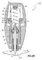
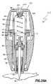
図33および図34を参照すると、ランセット装置10Fは、枢動棚340、作動手段342、ウィッキング材料300Fおよび枢動棚チャンバ348を含む。作動手段342は、ウィッキング材料300Fが、ランセット構造体70の穿刺要素74によって穿刺された患者の皮膚表面Sの一部と接触することができる位置まで、ウィッキング材料300Fを自動的に移動させることができる。一実施形態では、作動手段342は、ウィッキング材料300Fが、ランセット構造体70の穿刺要素74によって穿刺された患者の皮膚表面Sの一部と接触することができると同時に、ランセット構造体70の穿刺要素74が患者から血液サンプルを得るために患者の皮膚Sを穿刺するように駆動される位置まで、ウィッキング材料300Fを自動的に移動させることができる。一実施形態では、作動手段342はばね344を含む。  Referring to FIGS. 33 and 34, thelancet device 10F includes apivot shelf 340, an actuation means 342, awicking material 300F and apivot shelf chamber 348. The actuation means 342 automatically moves thewicking material 300F to a position where thewicking material 300F can contact a portion of the patient's skin surface S punctured by the piercingelement 74 of thelancet structure 70. be able to. In one embodiment, the actuation means 342 allows thewicking material 300F to contact a portion of the patient's skin surface S punctured by the piercingelement 74 of thelancet structure 70, while at the same time. The wickingmaterial 300F can be automatically moved to a position where the piercingelement 74 is driven to puncture the patient's skin S to obtain a blood sample from the patient. In one embodiment, actuation means 342 includes aspring 344.

ウィッキング材料300Fは、ランセット構造体70の起動時に形成されたランセット傷から引き出される第1量の血液を吸収することができる材料から作製される。たとえば、ウィッキング材料300Fは、コットンガーゼ、ウィッキング紙、プレス紙材料、吸収繊維、およびウィッキング特性を有するさまざまなプラスチック等のさまざまな吸収材料から形成することができる。ウィッキング材料300Fを作製するために使用される材料の重要な特性は、ランセット構造体70の起動時に形成されたランセット傷から引き出される第1量の血液を吸収し得ることである。  The wickingmaterial 300F is made of a material that can absorb a first amount of blood drawn from a lancet wound formed when thelancet structure 70 is activated. For example, the wickingmaterial 300F can be formed from a variety of absorbent materials, such as cotton gauze, wicking paper, pressed paper materials, absorbent fibers, and various plastics having wicking properties. An important property of the material used to make thewicking material 300F is that it can absorb a first amount of blood drawn from a lancet wound formed upon activation of thelancet structure 70.

図33を参照すると、枢動棚340は、図33に示すような拡張位置から図34に示すように後退位置まで移動することができる。一実施形態では、枢動棚340は、ヒンジ式接続部またはヒンジ部分346を介して拡張位置から後退位置まで移動することができる。枢動棚340は、図33に示すようなロック位置または拡張位置にある状態では、ウィッキング材料300Fを保持しばね344を圧縮する障壁または支持部材を提供する。枢動棚340は、図34に示すような後退位置にある状態では、枢動棚チャンバ348内に収容され、それにより、より詳細に上述したように、ランセット構造体70を、後部キャップ24から離れるように、ハウジング12およびシールド本体50ならびにウィッキング材料300Fを通って軸方向に下方に作動させることができる。図34に示すように、ランセット構造体70の作動中、ランセット構造体70の穿刺端部74は、患者から血液サンプルを得るために患者の皮膚を穿刺する。このように、ランセット装置10Fは、ウィッキング材料300Fが、ランセット構造体70の穿刺要素74によって穿刺される患者の皮膚表面Sの一部と接触することができると同時に、ランセット構造体70の穿刺要素74が、患者から血液サンプルを得るために患者の皮膚Sを穿刺するように駆動される位置まで、ウィッキング材料300Fを自動的に移動させることができる。いくつかの実施形態では、図34に示すように患者の皮膚Sと接触してウィッキング材料300Fを維持するのに役立つように、シールド本体50の前端壁58に構造体を含めることができる。  Referring to FIG. 33, thepivot shelf 340 can move from an extended position as shown in FIG. 33 to a retracted position as shown in FIG. In one embodiment,pivot shelf 340 can be moved from an extended position to a retracted position via a hinged connection orhinge portion 346. Thepivot shelf 340 provides a barrier or support member that holds thewicking material 300F and compresses thespring 344 when in the locked or expanded position as shown in FIG. Thepivot shelf 340, when in the retracted position as shown in FIG. 34, is contained within thepivot shelf chamber 348, thereby removing thelancet structure 70 from therear cap 24, as described in more detail above. Away, it can be actuated axially downward throughhousing 12 andshield body 50 andwicking material 300F. As shown in FIG. 34, during operation of thelancet structure 70, the piercingend 74 of thelancet structure 70 punctures the patient's skin to obtain a blood sample from the patient. In this manner, thelancet device 10F allows thewicking material 300F to contact a portion of the patient's skin surface S that is pierced by the piercingelement 74 of thelancet structure 70 while simultaneously puncturing thelancet structure 70. The wickingmaterial 300F can be automatically moved to a position where theelement 74 is driven to puncture the patient's skin S to obtain a blood sample from the patient. In some embodiments, a structure can be included in thefront end wall 58 of theshield body 50 to help maintain thewicking material 300F in contact with the patient's skin S, as shown in FIG.

図34に示すように、ランセット構造体70の作動中、ランセット構造体70の穿刺端部74は、ウィッキング材料300Fを貫通し、患者から血液サンプルを得るために患者の皮膚Sを穿刺する。ランセット構造体70の穿刺端部74が、患者から血液サンプルを得るために患者の皮膚Sを貫通している状態で、ウィッキング材料300Fはまた、ランセット構造体70の穿刺端部74によって穿刺される皮膚Sの部分と接触する位置まで自動的に移動する。このように、ウィッキング材料300Fは、患者の皮膚Sから血液の第1液滴を自動的に吸収し吸い取る。重要なことには、ランセット装置10Fにより、ウィッキング材料300Fは、いかなる追加のステップもなしに、患者の皮膚Sを穿刺するランセット装置の通常動作中に、患者の皮膚Sから血液の第1液滴を自動的に吸収し吸い取ることができる。このように、本開示のランセット装置10Fは、血液検査結果をより正確なものとする第1液滴除去プロセスに患者が従うのに役立つ効率的な装置を提供する。  As shown in FIG. 34, during operation of thelancet structure 70, the piercingend 74 of thelancet structure 70 penetrates thewicking material 300F and punctures the patient's skin S to obtain a blood sample from the patient.Wicking material 300F is also pierced by piercingend 74 oflancet structure 70, with piercingend 74 oflancet structure 70 penetrating skin S of the patient to obtain a blood sample from the patient. Automatically moves to a position where it comes into contact with a portion of the skin S. In this manner, the wickingmaterial 300F automatically absorbs and absorbs the first drop of blood from the patient's skin S. Importantly, with thelancet device 10F, the wickingmaterial 300F allows the first fluid of blood from the patient's skin S during normal operation of the lancet device to puncture the patient's skin S without any additional steps. Drops can be automatically absorbed and sucked. Thus, thelancet device 10F of the present disclosure provides an efficient device that helps the patient to follow the first droplet removal process that makes blood test results more accurate.

ランセット装置の具体的な実施形態について記載したが、当業者は、本発明の範囲および趣旨から逸脱することなく、変更形態および改変形態をなし得る。したがって、上述した詳細な説明は、限定するものではなく例示するものであるように意図される。本発明は、添付の特許請求の範囲によって定義され、特許請求の範囲の均等物の意味および範囲内にある本発明に対するすべての変更形態は、それらの範囲に包含されるべきである。  Although specific embodiments of the lancet device have been described, those skilled in the art can make modifications and variations without departing from the scope and spirit of the invention. Therefore, the above detailed description is intended to be illustrative, not limiting. The invention is defined by the following claims, and all modifications of the invention that come within the meaning and range of equivalents of the claims are to be embraced within their scope.

Claims (1)

Translated fromJapanese
前端部および後端部を備えるハウジングと、
穿刺要素を備えるランセット構造体であって、前記ハウジング内に少なくとも部分的に配置され、かつ前記穿刺要素が前記ハウジング内に保持される作動前位置と、前記穿刺要素の少なくとも一部が前記ハウジングの前記前端部を通って延在する穿刺位置との間で移動するように適合されたランセット構造体と、
前記ランセット構造体の前記穿刺要素を取外し可能に覆う柱部分を含む保護カバーと、
前記保護カバーの前記柱部分の一部に配置されたウィッキング要素と
を備えるランセット装置。
A housing having a front end and a rear end;
A lancet structure comprising a piercing element, wherein the lancet structure is at least partially disposed within the housing, and wherein the puncturing element is held in the housing in a pre-actuated position, and wherein at least a portion of the piercing element is located in the housing. A lancet structure adapted to move between a puncture position extending through the front end;
A protective cover including a pillar portion that removably covers the puncturing element of the lancet structure;
A wicking element disposed on a part of the pillar portion of the protective cover.
JP2017503016A2014-07-182015-07-09 Lancet device for removing first dropletActiveJP6640830B2 (en)

Applications Claiming Priority (3)

Application NumberPriority DateFiling DateTitle
US201462026169P2014-07-182014-07-18
US62/026,1692014-07-18
PCT/US2015/039721WO2016010817A1 (en)2014-07-182015-07-09Lancet device with first-drop removal

Related Child Applications (1)

Application NumberTitlePriority DateFiling Date
JP2019200971ADivisionJP7189113B2 (en)2014-07-182019-11-05 Lancet device for removing the first droplet

Publications (2)

Publication NumberPublication Date
JP2017522117A JP2017522117A (en)2017-08-10
JP6640830B2true JP6640830B2 (en)2020-02-05

Family

ID=53716595

Family Applications (3)

Application NumberTitlePriority DateFiling Date
JP2017503016AActiveJP6640830B2 (en)2014-07-182015-07-09 Lancet device for removing first droplet
JP2019200971AActiveJP7189113B2 (en)2014-07-182019-11-05 Lancet device for removing the first droplet
JP2021185740AActiveJP7268118B2 (en)2014-07-182021-11-15 Lancet device for removing the first droplet

Family Applications After (2)

Application NumberTitlePriority DateFiling Date
JP2019200971AActiveJP7189113B2 (en)2014-07-182019-11-05 Lancet device for removing the first droplet
JP2021185740AActiveJP7268118B2 (en)2014-07-182021-11-15 Lancet device for removing the first droplet

Country Status (7)

CountryLink
US (2)US9743876B2 (en)
EP (4)EP4233723A3 (en)
JP (3)JP6640830B2 (en)
CN (2)CN111419247A (en)
AU (4)AU2015290049B2 (en)
ES (3)ES2761425T3 (en)
WO (1)WO2016010817A1 (en)

Families Citing this family (13)

* Cited by examiner, † Cited by third party
Publication numberPriority datePublication dateAssigneeTitle
US9788771B2 (en)2006-10-232017-10-17Abbott Diabetes Care Inc.Variable speed sensor insertion devices and methods of use
USD762298S1 (en)2013-09-102016-07-26Theranos, Inc.Blood collection device
ES2760649T3 (en)*2015-02-242020-05-14Facet Tech Llc Single-use compression lancing device
JP7142569B2 (en)2015-09-092022-09-27ドローブリッジ ヘルス,インコーポレイテッド Systems, methods and devices for sample collection, stabilization and storage
GB2590813B (en)2017-01-102021-10-27Drawbridge Health IncDevices, systems, and methods for sample collection
US10530603B2 (en)*2017-01-112020-01-07Smartiply, Inc.Intelligent multi-modal IOT gateway
US11071478B2 (en)2017-01-232021-07-27Abbott Diabetes Care Inc.Systems, devices and methods for analyte sensor insertion
CN112423664B (en)2018-06-072025-01-21雅培糖尿病护理公司 Focused sterilization and sterilized sub-assemblies for analyte monitoring systems
GB2577869A (en)*2018-09-282020-04-15Owen Mumford LtdA blood sampling device
CN116649965A (en)*2019-08-312023-08-29深圳硅基传感科技有限公司 Pushing device with bias
USD952146S1 (en)*2020-07-072022-05-17Medivena Sp. Z O.O.Safety lancet
CA3188510A1 (en)2020-08-312022-03-03Vivek S. RAOSystems, devices, and methods for analyte sensor insertion
CN114028223B (en)*2021-12-262024-07-09广东省新黄埔中医药联合创新研究院Aseptically packaged acupuncture needle box and acupuncture needle inserting device

Family Cites Families (79)

* Cited by examiner, † Cited by third party
Publication numberPriority datePublication dateAssigneeTitle
CH500707A (en)*1968-07-261970-12-31Micromedic Systems Inc Device for performing percutaneous and digital blood sampling
CH522395A (en)*1968-07-261972-05-15Micromedic Systems Inc Test tube intended for percutaneous and digital blood sampling
CH538277A (en)1970-09-041973-06-30Micromedic Systems Inc Percutaneous blood test device
JPS5238140B2 (en)1973-05-181977-09-27
DE3011211A1 (en)1980-03-221981-10-01Clinicon Mannheim GmbH, 6800 Mannheim BLOOD PLANT DEVICE FOR TAKING BLOOD FOR DIAGNOSTIC PURPOSES
US4388925A (en)1981-03-231983-06-21Becton Dickinson And CompanyAutomatic retractable lancet assembly
US4535769A (en)1981-03-231985-08-20Becton, Dickinson And CompanyAutomatic retractable lancet assembly
US4577630A (en)1984-02-141986-03-25Becton, Dickinson And Co.Reusable breach loading target pressure activated lancet firing device
US4635633A (en)*1984-12-171987-01-13Hufnagle Douglas RCombination sterile pad support and lancet
US4627445A (en)1985-04-081986-12-09Garid, Inc.Glucose medical monitoring system
JPS61286738A (en)*1985-06-141986-12-17オ−デイオバイオニクス インコ−ポレイテツドMedical system
US4653513A (en)1985-08-091987-03-31Dombrowski Mitchell PBlood sampler
GB8618578D0 (en)1986-07-301986-09-10Turner R CLancet device
GB8710470D0 (en)1987-05-011987-06-03Mumford Ltd OwenBlood sampling devices
US4924879A (en)1988-10-071990-05-15Brien Walter J OBlood lancet device
US5108889A (en)*1988-10-121992-04-28Thorne, Smith, Astill Technologies, Inc.Assay for determining analyte using mercury release followed by detection via interaction with aluminum
GB8924937D0 (en)1989-11-041989-12-28Owen Mumford LtdImprovements relating to blood sampling devices
US4994068A (en)1989-11-241991-02-19Unidex, Inc.Combination sterile pad support and lancet containing lancet disposal element
CA2123400A1 (en)1991-11-121993-05-27Urs A. RamelLancet device
US5318583A (en)1992-05-051994-06-07Ryder International CorporationLancet actuator mechanism
PL169210B1 (en)1992-08-031996-06-28Przed Zagraniczne HtlPuncturing device
US5314441A (en)1992-10-161994-05-24International Technidyne CorporationDisposable slicing lancet assembly
JPH06238140A (en)1993-02-181994-08-30Toto LtdFilter membrane
US5540664A (en)1993-05-271996-07-30Washington Biotech CorporationReloadable automatic or manual emergency injection system
US5383885A (en)*1993-06-291995-01-24Bland; Todd A.Blood collection and testing device
US5439473A (en)1993-12-131995-08-08Modulohm A/SSafety lancet
GB9422260D0 (en)1994-11-041994-12-21Owen Mumford LtdImprovements relating to skin prickers
US5628765A (en)1994-11-291997-05-13Apls Co., Ltd.Lancet assembly
KR0135178Y1 (en)1995-06-261999-03-20김인환 Blood collection lancet
JPH09168530A (en)*1995-10-171997-06-30Dainippon Printing Co Ltd Body fluid collecting device and body fluid analyzer using the same
US5643306A (en)1996-03-221997-07-01Stat Medical Devices Inc.Disposable lancet
EP1579814A3 (en)*1996-05-172006-06-14Roche Diagnostics Operations, Inc.Methods and apparatus for sampling and analyzing body fluid
US7828749B2 (en)*1996-05-172010-11-09Roche Diagnostics Operations, Inc.Blood and interstitial fluid sampling device
US5714390A (en)*1996-10-151998-02-03Bio-Tech Imaging, Inc.Cartridge test system for the collection and testing of blood in a single step
US5984940A (en)1997-05-291999-11-16Atrion Medical Products, Inc.Lancet device
DE69822487T2 (en)1997-06-022005-03-24Paul Viranyi BRACKET OF LANZETTS TO POINT UP THE SKIN
US5871494A (en)*1997-12-041999-02-16Hewlett-Packard CompanyReproducible lancing for sampling blood
US5908434A (en)1998-02-131999-06-01Schraga; StevenLancet device
US6053930A (en)1998-05-112000-04-25Ruppert; NorbertSingle use lancet assembly
SG85117A1 (en)1999-06-182001-12-19Surgilance Pte LtdLancet assembly
US6168606B1 (en)1999-11-102001-01-02Palco Labs, Inc.Single-use lancet device
PL189108B1 (en)1999-09-062005-06-30Htl Strefa Sp Z OoPuncturing device
CA2287757A1 (en)1999-10-292001-04-29Medical Plastic Devices M.P.D. Inc.Disposable lancet
US6258112B1 (en)1999-11-022001-07-10Steven SchragaSingle use lancet assembly
US6248120B1 (en)2000-01-102001-06-19P. Z. “HTL” Spolka AkcyjnaPuncturing device
PL191428B1 (en)2000-04-062006-05-31Htl Strefa Sp Z OoPuncturing depth adjusting assembly for puncturing devices
US6514270B1 (en)2000-11-102003-02-04Steven SchragaSingle use lancet device
US6540763B2 (en)2001-02-202003-04-01Medisys Asia Pacific Pte Ltd.Lancet device with retractable sharps member
US20020188223A1 (en)*2001-06-082002-12-12Edward PerezDevices and methods for the expression of bodily fluids from an incision
US7264627B2 (en)*2001-08-292007-09-04Roche Diagnostics Operations, Inc.Wicking methods and structures for use in sampling bodily fluids
KR20030042393A (en)2001-11-222003-05-28신백식A disposal lancet
WO2003073936A2 (en)2002-03-062003-09-12'htl Strefa' Sp. Z O.O.A device for puncturing patient's skin
DE10222235A1 (en)2002-05-162003-11-27Roche Diagnostics Gmbh Blood Collection system
DE10223558A1 (en)2002-05-282003-12-11Roche Diagnostics GmbhSystem useful in withdrawing blood for diagnostic purposes, has housing, lancet guide and lancet drive provided with drive spring, cocking device, drive rotor and outputs side coupling mechanism
US6997913B2 (en)2002-06-072006-02-14Becton, Dickinson And CompanyNeedle safety device
WO2004039429A2 (en)2002-10-292004-05-13Palco Labs, Inc.Single-use lancet device
JP2005028109A (en)*2003-04-232005-02-03Matsushita Electric Ind Co Ltd Lancet device and its storage container
USD499182S1 (en)2003-06-112004-11-30Palco Labs, Inc.Single use lancet
DE10326692B3 (en)*2003-06-132005-02-17Roche Diagnostics Gmbh Blood collection system, blood analyzer and method for taking blood
JP2005177028A (en)*2003-12-172005-07-07Terumo CorpPuncture implement and body fluid collection implement
US9380975B2 (en)2004-05-072016-07-05Becton, Dickinson And CompanyContact activated lancet device
CN1968651A (en)*2004-05-072007-05-23贝克顿·迪金森公司 Cam actuated medical piercing device and method
US9066688B2 (en)*2004-05-072015-06-30Becton, Dickinson And CompanyContact activated lancet device
KR101121072B1 (en)*2004-05-072012-03-15벡톤 디킨슨 앤드 컴퍼니Contact activated lancet device
US20060100655A1 (en)*2004-10-282006-05-11Koon-Wah LeongCombined lancing and auxiliary device
PL2425776T3 (en)2005-04-072013-12-31Becton Dickinson CoLancet device
JP2007082954A (en)2005-09-262007-04-05Terumo CorpComponent measurement tip
GB0524284D0 (en)2005-11-292006-01-04Touch Emas LtdProsthesis
GB2440119A (en)*2006-07-182008-01-23Owen Mumford LtdSkin Pricking Device
TW200841856A (en)*2006-11-222008-11-01Johnson & Johnson ConsumerSkin-piercing device for treatment of acne
JP2010286738A (en)2009-06-122010-12-24Sharp Corp Display device and electronic device
BR112012004688A2 (en)*2009-09-042019-09-24Atomo Diagnostics Pty Ltd sampling device to collect a body fluid.
CA2793554C (en)*2010-03-192018-04-03Atomo Diagnostics Pty LimitedBodily fluid diagnostic system
US9040236B2 (en)*2010-08-262015-05-26Spot On Sciences, Inc.Biological fluid sampling and storage apparatus for remote use
CN104080403A (en)*2011-11-252014-10-01赛诺菲-安万特德国有限公司Apparatus for eliciting blood sample
US9526446B2 (en)*2012-06-012016-12-27Sanofi-Aventis Deutschland GmbhTesting member for eliciting a blood sample
CN102866038A (en)*2012-09-262013-01-09广东凯普生物科技股份有限公司Blood cake specimen collecting and treating method and collection card dry blood cake DNA (deoxyribose nucleic acid) extracting method thereof
CN103169483A (en)*2013-04-182013-06-26于世质Terminal blood taking device
CN203447295U (en)*2013-09-092014-02-26刘岚Micrangium amplification blood sampling instrument

Also Published As

Publication numberPublication date
AU2015290049A1 (en)2017-02-09
US9743876B2 (en)2017-08-29
ES2954498T3 (en)2023-11-22
EP3169236B1 (en)2019-09-18
AU2018220065B2 (en)2019-12-19
JP2022028801A (en)2022-02-16
WO2016010817A1 (en)2016-01-21
AU2015290049B2 (en)2018-09-06
JP7189113B2 (en)2022-12-13
EP3616617C0 (en)2023-08-30
JP7268118B2 (en)2023-05-02
EP3616617A1 (en)2020-03-04
AU2018220062A1 (en)2018-09-06
CN111419247A (en)2020-07-17
US20170319120A1 (en)2017-11-09
ES2761425T3 (en)2020-05-19
US10682085B2 (en)2020-06-16
AU2018220062B2 (en)2019-12-19
EP3598944B1 (en)2021-03-03
ES2864412T3 (en)2021-10-13
EP4233723A3 (en)2023-09-20
AU2018220064A1 (en)2018-09-06
EP3169236A1 (en)2017-05-24
JP2020072911A (en)2020-05-14
JP2017522117A (en)2017-08-10
EP4233723A2 (en)2023-08-30
CN106687040B (en)2020-06-09
US20160015305A1 (en)2016-01-21
AU2018220065A1 (en)2018-09-13
EP3598944A1 (en)2020-01-29
AU2018220064B2 (en)2019-12-19
CN106687040A (en)2017-05-17
EP3616617B1 (en)2023-08-30

Similar Documents

PublicationPublication DateTitle
JP7268118B2 (en) Lancet device for removing the first droplet
JP6511426B2 (en) Contact-operated lancet device
EP2263538B1 (en)Contact Activated Lancet Device
AU2012202665B2 (en)Contact activated lancet device

Legal Events

DateCodeTitleDescription
A621Written request for application examination

Free format text:JAPANESE INTERMEDIATE CODE: A621

Effective date:20170316

A131Notification of reasons for refusal

Free format text:JAPANESE INTERMEDIATE CODE: A131

Effective date:20180227

A977Report on retrieval

Free format text:JAPANESE INTERMEDIATE CODE: A971007

Effective date:20180223

A521Request for written amendment filed

Free format text:JAPANESE INTERMEDIATE CODE: A523

Effective date:20180528

A131Notification of reasons for refusal

Free format text:JAPANESE INTERMEDIATE CODE: A131

Effective date:20181030

A521Request for written amendment filed

Free format text:JAPANESE INTERMEDIATE CODE: A523

Effective date:20190130

A02Decision of refusal

Free format text:JAPANESE INTERMEDIATE CODE: A02

Effective date:20190702

A521Request for written amendment filed

Free format text:JAPANESE INTERMEDIATE CODE: A523

Effective date:20191105

C60Trial request (containing other claim documents, opposition documents)

Free format text:JAPANESE INTERMEDIATE CODE: C60

Effective date:20191105

A911Transfer to examiner for re-examination before appeal (zenchi)

Free format text:JAPANESE INTERMEDIATE CODE: A911

Effective date:20191112

C21Notice of transfer of a case for reconsideration by examiners before appeal proceedings

Free format text:JAPANESE INTERMEDIATE CODE: C21

Effective date:20191119

TRDDDecision of grant or rejection written
A01Written decision to grant a patent or to grant a registration (utility model)

Free format text:JAPANESE INTERMEDIATE CODE: A01

Effective date:20191203

A61First payment of annual fees (during grant procedure)

Free format text:JAPANESE INTERMEDIATE CODE: A61

Effective date:20191226

R150Certificate of patent or registration of utility model

Ref document number:6640830

Country of ref document:JP

Free format text:JAPANESE INTERMEDIATE CODE: R150

R250Receipt of annual fees

Free format text:JAPANESE INTERMEDIATE CODE: R250

R250Receipt of annual fees

Free format text:JAPANESE INTERMEDIATE CODE: R250

R250Receipt of annual fees

Free format text:JAPANESE INTERMEDIATE CODE: R250


[8]ページ先頭

©2009-2025 Movatter.jp