JP6633580B2 - Robot system and robot controller - Google Patents
Robot system and robot controllerDownload PDFInfo
- Publication number
- JP6633580B2 JP6633580B2JP2017150075AJP2017150075AJP6633580B2JP 6633580 B2JP6633580 B2JP 6633580B2JP 2017150075 AJP2017150075 AJP 2017150075AJP 2017150075 AJP2017150075 AJP 2017150075AJP 6633580 B2JP6633580 B2JP 6633580B2
- Authority
- JP
- Japan
- Prior art keywords
- robot
- sensor
- unit
- finger
- contact
- Prior art date
- Legal status (The legal status is an assumption and is not a legal conclusion. Google has not performed a legal analysis and makes no representation as to the accuracy of the status listed.)
- Active
Links
Images


Classifications
- B—PERFORMING OPERATIONS; TRANSPORTING
- B25—HAND TOOLS; PORTABLE POWER-DRIVEN TOOLS; MANIPULATORS
- B25J—MANIPULATORS; CHAMBERS PROVIDED WITH MANIPULATION DEVICES
- B25J13/00—Controls for manipulators
- B25J13/08—Controls for manipulators by means of sensing devices, e.g. viewing or touching devices
- B25J13/081—Touching devices, e.g. pressure-sensitive
- B25J13/084—Tactile sensors
- B—PERFORMING OPERATIONS; TRANSPORTING
- B25—HAND TOOLS; PORTABLE POWER-DRIVEN TOOLS; MANIPULATORS
- B25J—MANIPULATORS; CHAMBERS PROVIDED WITH MANIPULATION DEVICES
- B25J9/00—Programme-controlled manipulators
- B25J9/16—Programme controls
- B25J9/1602—Programme controls characterised by the control system, structure, architecture
- B—PERFORMING OPERATIONS; TRANSPORTING
- B25—HAND TOOLS; PORTABLE POWER-DRIVEN TOOLS; MANIPULATORS
- B25J—MANIPULATORS; CHAMBERS PROVIDED WITH MANIPULATION DEVICES
- B25J13/00—Controls for manipulators
- B25J13/08—Controls for manipulators by means of sensing devices, e.g. viewing or touching devices
- B25J13/081—Touching devices, e.g. pressure-sensitive
- B—PERFORMING OPERATIONS; TRANSPORTING
- B25—HAND TOOLS; PORTABLE POWER-DRIVEN TOOLS; MANIPULATORS
- B25J—MANIPULATORS; CHAMBERS PROVIDED WITH MANIPULATION DEVICES
- B25J13/00—Controls for manipulators
- B25J13/08—Controls for manipulators by means of sensing devices, e.g. viewing or touching devices
- B25J13/088—Controls for manipulators by means of sensing devices, e.g. viewing or touching devices with position, velocity or acceleration sensors
- B—PERFORMING OPERATIONS; TRANSPORTING
- B25—HAND TOOLS; PORTABLE POWER-DRIVEN TOOLS; MANIPULATORS
- B25J—MANIPULATORS; CHAMBERS PROVIDED WITH MANIPULATION DEVICES
- B25J9/00—Programme-controlled manipulators
- B25J9/0009—Constructional details, e.g. manipulator supports, bases
- B—PERFORMING OPERATIONS; TRANSPORTING
- B25—HAND TOOLS; PORTABLE POWER-DRIVEN TOOLS; MANIPULATORS
- B25J—MANIPULATORS; CHAMBERS PROVIDED WITH MANIPULATION DEVICES
- B25J9/00—Programme-controlled manipulators
- B25J9/0081—Programme-controlled manipulators with leader teach-in means
- B—PERFORMING OPERATIONS; TRANSPORTING
- B25—HAND TOOLS; PORTABLE POWER-DRIVEN TOOLS; MANIPULATORS
- B25J—MANIPULATORS; CHAMBERS PROVIDED WITH MANIPULATION DEVICES
- B25J9/00—Programme-controlled manipulators
- B25J9/16—Programme controls
- B25J9/1656—Programme controls characterised by programming, planning systems for manipulators
- B25J9/1664—Programme controls characterised by programming, planning systems for manipulators characterised by motion, path, trajectory planning
- G—PHYSICS
- G05—CONTROLLING; REGULATING
- G05B—CONTROL OR REGULATING SYSTEMS IN GENERAL; FUNCTIONAL ELEMENTS OF SUCH SYSTEMS; MONITORING OR TESTING ARRANGEMENTS FOR SUCH SYSTEMS OR ELEMENTS
- G05B19/00—Programme-control systems
- G05B19/02—Programme-control systems electric
- G05B19/42—Recording and playback systems, i.e. in which the programme is recorded from a cycle of operations, e.g. the cycle of operations being manually controlled, after which this record is played back on the same machine
- G05B19/425—Teaching successive positions by numerical control, i.e. commands being entered to control the positioning servo of the tool head or end effector
Landscapes
- Engineering & Computer Science (AREA)
- Robotics (AREA)
- Mechanical Engineering (AREA)
- Human Computer Interaction (AREA)
- Automation & Control Theory (AREA)
- Physics & Mathematics (AREA)
- General Physics & Mathematics (AREA)
- Manipulator (AREA)
Description
Translated fromJapanese本発明は、ロボットシステム及びロボット制御装置に関する。 The present invention relates to a robot system and a robot control device.
ロボットの動作の教示を行うための手段として、作業者が操作可能な教示操作盤が知られている。一方、他の教示手段として、作業者がロボットに力を作用させて該ロボットを移動させることによってロボットの教示を行う、いわゆるダイレクトティーチングが知られている(例えば特許文献1〜5参照)。 As a means for teaching the operation of a robot, a teaching operation panel operable by an operator is known. On the other hand, as another teaching means, a so-called direct teaching in which an operator applies a force to a robot and moves the robot to teach the robot is known (for example, see Patent Documents 1 to 5).
教示操作盤による作業は熟練を要し、不慣れな作業者では教示に時間がかかるという問題があった。一方、ダイレクトティーチングを利用した場合、作業者は直感的にロボットの移動方向を決めることができるので、教示操作盤を利用した場合よりも簡単に教示を行うことができる場合が多い。しかしダイレクトティーチングを利用するためには、作業者が把持・操作する教示用ハンドル等の専用装置をロボット(多くの場合、ハンド等のロボット先端部)に取り付ける必要があり、またその取り付け位置は容易には変更できない。 The operation using the teaching operation panel requires skill, and there is a problem that an inexperienced operator takes a long time to teach. On the other hand, when direct teaching is used, the operator can intuitively determine the moving direction of the robot, and in many cases, teaching can be performed more easily than when using the teaching operation panel. However, in order to use direct teaching, it is necessary to attach a dedicated device such as a teaching handle that is gripped and operated by the operator to the robot (in many cases, the tip of the robot such as a hand), and the attachment position is easy. Cannot be changed.
本開示の一態様は、可動部を備えたロボットと、前記可動部の表面に設けられるセンサであって、物体が前記センサに接触又は近接した状態における前記物体の3次元位置を測定するセンサと、前記物体が前記センサに接触又は近接している基準位置に到達したときに、前記ロボットを追従モードに移行させるモード切替部と、前記物体の3次元位置が前記基準位置から変化したときに、該変化の方向に応じて前記物体に前記可動部が追従する追従動作を前記ロボットに行わせる動作制御部と、を有し、前記ロボットは、前記可動部を覆うカバー部材を有し、前記センサは前記カバー部材の内側に配置される、ロボットシステムである。One aspect of the present disclosure is a robot including a movable unit, asensor provided on a surface of the movable unit, anda sensor that measures a three-dimensional position of the object in a state where the object is in contact with or in proximity to the sensor . A mode switching unit that shifts the robot to a tracking mode when the object reaches a reference position that is in contact with or in proximity to thesensor; and when the three-dimensional position of the object changes from the reference position, An operation control unit that causes the robot to perform a following operation in which the movable unit follows the object in accordance with the direction of the change, wherein the robot has a cover member that covers the movable unit, and the sensor Is a robot systemarranged inside the cover member .
本開示の他の態様は、可動部と、前記可動部の表面に設けられるセンサであって、物体が前記センサに接触又は近接した状態における前記物体の3次元位置を測定するセンサとを有するロボットの制御装置において、前記物体が前記センサに接触又は近接している基準位置に到達したときに、前記ロボットを追従モードに移行させるモード切替部と、前記物体の3次元位置が前記基準位置から変化したときに、該変化の方向に応じて前記物体に前記可動部が移動する追従動作を前記ロボットに行わせる動作制御部と、を有し、前記動作制御部は、前記センサを設けた前記可動部の部位よりも前記ロボットの先端側の可動部が、前記追従モードにおいて動作しないようにする、ロボット制御装置である。Another aspect of the present disclosureis a robot having amovable part and a sensor provided on a surface of the movable part, the sensor being configured to measure a three-dimensional position of the object when the object is in contact with or in proximity to the sensor. A control unit that switches the robot to a following mode when the object reaches a reference position where the object is in contact with or in proximity to the sensor; and a three-dimensional position of the object changes from the reference position. And an operation control unit that causes the robot to perform a following operation in which the movable unit moves on the object according to the direction of the change, wherein the operation control unit includes the sensor. A robot control device that prevents a movable part on the tip side of the robot from a part of the part from operating in the following mode .
本開示によれば、センサに接触又は近接した物体の3次元位置の変化に応じて、ロボットの可動部の追従動作を行わせることができるので、簡単な操作で直感的にロボットの教示等の動作制御を行うことができる。 According to the present disclosure, the following operation of the movable part of the robot can be performed according to a change in the three-dimensional position of the object that is in contact with or in proximity to the sensor. Operation control can be performed.
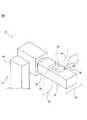
図1は、好適な実施形態に係るロボット(機構部)10及びロボット制御装置20を含むロボットシステム8の概略構成例を示す図である。ロボット10としては、ロボットアーム等の可動部を有するものであれば種々のものが使用可能であるが、図示されたロボット10は垂直多関節ロボットであり、人間と作業空間を共有して稼働する人間協調型ロボットである。ロボット10は、基部12と、基部12に設けられ、略鉛直方向軸線回りに回転可能な旋回胴14と、旋回胴14に回転可能に設けられた上腕16と、上腕16の先端に回転可能に設けられた前腕18とを有する。 FIG. 1 is a diagram illustrating a schematic configuration example of a robot system 8 including a robot (mechanical unit) 10 and a
ロボット10では、可動部(ここでは旋回胴14、上腕16及び前腕18の少なくとも1つ)を回転させることにより、ロボット10の先端位置(前腕18の先端部)を移動・制御できるようになっている。また、前腕18の先端にさらに手首軸及びハンド(図示せず)等を設け、ロボットにワークの把持や搬送等の、種々の作業を行わせることができる。 The
ロボット10の教示や動作制御は、ロボット10に接続されたロボット制御装置20によって行うことができる。ロボット制御装置20は、モード切替部22及び動作制御部24を有するが、それらの機能については後述する。またモード切替部22及び動作制御部24(又はそれらの機能)は、制御装置20が有する演算処理装置(CPU)やメモリ等によって実現することができるが、制御装置20とは別に設けられたパーソナルコンピュータ又はホストコンピュータ等の装置(図示せず)によって実現することもできる。 Teaching and operation control of the
ロボット10は、ロボット10の可動部(図示例では前腕18)の表面に設けられたセンサ26を有し、センサ26は、作業者の指等の物体28(図2参照)がセンサ26に接触又は近接した状態における物体28の3次元位置を測定するように構成されている。一例として、拡大図2に示すように、センサ26は感圧式センサであり、複数の感圧センサ要素30を有する。複数の感圧センサ要素30は、可動部(ここでは前腕18)の表面に列状(好ましくは図示例のような格子状)に配置されており、物体28がセンサ26に接触しているときに、物体28の3次元位置を測定することができる。 The
図3は、センサ26によって物体28の3次元位置を測定している状態を説明する図である。センサ26は、前腕18等の可動部の表面32に所定の間隔で整列配置された複数の感圧センサ要素30と、複数の感圧センサ要素30全体を覆うように、各感圧センサ要素30から所定の間隔dだけ離隔して配置された、アルミニウム等の金属からなる電極層34とを有する。なお以降の説明では、電極層34は比較的柔軟性のある電極膜として説明するが、電極膜よりも剛性の高い板状の電極層(電極板)等も電極層34として使用可能である。 FIG. 3 is a diagram illustrating a state where the three-dimensional position of the
作業者の指等の物体28が電極膜34に接触すると、センサ26に対する指28の押圧力に応じて電極膜34が変形し、電極膜34と各センサ要素30との距離が変化する(非接触時のdより小さくなる)。このときの距離の変化を、電気的な抵抗又は静電容量の変化等から検出することにより、センサ26は指28の3次元的な位置を測定することができる。 When an
次に、センサ26を用いたロボット10の追従機能を、ロボット制御装置20を用いてロボット10の教示を行う場合を例として説明する。先ず、図3に示したような、物体28がセンサ26に接触しているときの物体28の所定の3次元位置を、ロボット10を追従モードに移行させるための基準位置として、ロボット制御装置20のメモリ等に記憶しておく。この基準位置は任意に定めることができ、例えば複数の感圧センサ要素30のいずれか1つが、指28が電極膜34を押圧したことを検出したときに指28が基準位置に到達したと判断してもよいし、電極膜34を押圧されたことを、予め定めた特定の感圧センサ要素30が検出したときにのみ指28が基準位置に到達したと判断してもよい。或いは又はこれに加え、指28とある感圧センサ要素30との距離が、非接触時(初期)のdに対して所定の割合(例えばdの2/3、1/2又は1/3)になったときに指28が基準位置に到達したと判断してもよい。 Next, the following function of the
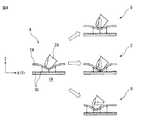
次に、指28が上述の基準位置に到達したときに、上述のモード切替部22が、ロボット10の動作モードを追従モードに切り替える。この追従モードでは、基準位置から指28がどの方向に移動したかに基づいて、ロボット10の動作(方向)を決定する。例えば、図4のA部に示す指28の3次元位置を基準位置とした場合を考える。ここでB部に示すように、指28が基準位置からZ方向に、前腕18から離れるように移動したときは、上述の動作制御部24が、指28が接触している前腕18の部位(センサ26)が指28の移動方向と概ね同方向(図2の矢印36で示す方向)に移動(すなわち追従)するようにロボット10の各軸の動作を制御する。なお本実施例では、感圧センサ要素30と電極膜34との間の距離(d)の方向(表面32に垂直な方向)をZ方向とし、Z方向に垂直でかつ互いに直交する2つの方向をそれぞれX方向及びY方向とする。 Next, when the
同様に、C部に示すように、指28が基準位置からZ方向に、前腕18を押し込むように移動したときは、動作制御部24は、指28が接触している前腕18の表面(センサ26)が指28の移動方向と概ね同方向(図2の矢印38で示す方向)に移動(すなわち追従)するようにロボット10の各軸の動作を制御する。また、D部に示すように、指28が基準位置からX方向又はY方向に、センサ26上を摺動するように移動したときも、動作制御部24は、指28が接触している前腕18の部位(センサ26)が指28の移動方向と概ね同方向(図2の矢印40で示す方向)に移動(すなわち追従)するようにロボット10の各軸の動作を制御する。 Similarly, when the
またセンサ26に対する指の押圧力や相対速度に応じて、ロボット10の可動部の移動速度が変化するようにしてもよい。例えば、図4のC部に示す場合において、作業者が指28をセンサ26に対して強く(素早く)押し込んだ場合や、図4のD部に示す場合において、作業者が指28をセンサ26に対して素早く移動させた場合は、ロボット10の可動部を指28の速度に応じて高速で移動させることができる。 Further, the moving speed of the movable part of the
なお追従モード(教示)を終了させたい場合又は他のモードに切り替えたい場合、例えば、作業者が一定速度(例えばロボットの上限動作速度)より大きい速度で指をセンサ26から離したときに、モード切替部22が追従モードの終了又は他モードへの切替えを行うようにすることができる。 If the operator wants to end the following mode (teaching) or switch to another mode, for example, when the operator releases his / her finger from the
このようにして作業者は、簡単な操作によってロボット10の移動方向を決定して動作させることができるので、教示操作盤等を使用せずとも、短時間で直感的にロボットの教示等を行うことができる。一般に感圧式センサや後述する静電容量式近接センサは、接触又は近接した物体の座標と押圧力(接離方向についての距離)の双方を高精度に検出できるという性質があり、本開示ではこの性質を、ロボット10の可動部を所望の方向に簡易に移動させるために利用することができる。またセンサ26は予めロボット10に設けられているので、教示のために別途、ハンドルやガイド等の専用機器をロボット10に取り付ける必要もない。 In this way, the worker can determine the moving direction of the
図示例ではセンサ26はロボット10の前腕18に設けられているが、これの代わりに又はこれに加え、同様のセンサを旋回胴14や上腕16等の他の可動部に設けてもよい。また動作制御部24は、センサ26を設けた部位よりもロボット先端側(基部の反対側)の構成要素が、追従モードにおいて動作(回転)しないようにすることができる。例えば、センサ26を上腕16に設けた場合、動作制御部24は追従モードにおいて、図4のような操作によって旋回胴14及び上腕16は追従動作をするが、前腕18は上腕16に対して回転しないような動作制御を行うことができる。このように本開示では、センサ26の配置位置によって、追従モードにおいて駆動(動作)させるべき要素とさせない要素とを使い分けることができる。 Although the
ロボット制御装置20は、作業者の指等の物体28が基準位置に到達したとき、すなわちロボット10が追従モードに移行した(追従動作が可能となった)ときに、その旨を表す通知信号を出力する通知部42をさらに有してもよい。通知部42は例えば、指28が基準位置に到達したことをセンサ26が検知したときに音声を出力するスピーカや、ロボット10の動作モードが追従モードに切り替わった旨を表示するディスプレイを有し、これらのスピーカ又はディスプレイは上記通知信号によって作動可能に構成される。なお上記スピーカやディスプレイは、制御装置20以外の装置として提供することもできる。また通知部42は、追従モードが終了したことを、音声や画面表示によって作業者に知らせるようにしてもよい。このようにすれば作業者は、現時点が追従モードか否かを正しく認識できるので、教示操作等を安心して行うことができる。 When the
図1又は図2に示すように、ロボット10が人間と作業領域を共有する人間協調型ロボットである場合、ロボット10が人間に衝突したときの衝撃を緩和するために、ロボット10の可動部(図示例では上腕16及び前腕18)の少なくとも一部、好ましくは全体を柔軟性のあるカバー部材44で覆うことが多い。本開示では、上腕16や前腕18等の可動部の表面にセンサ26が配置されるが、センサ26の配置形態としては、該センサの構成要素(例えば電極膜34)が外部に露出しており、指28等の物体が直接その構成要素に接触できる形態や、ロボット10がカバー部材44を有する場合に、外部に露出しないようにカバー部材44の内側(カバー部材44と前腕18等の可動部の表面との間)に配置される形態も含まれ、後者の場合、作業者は教示等を行う際、センサ26(電極膜34)にカバー部材44を介して間接的に接触することになる。但しいずれの場合も、センサ26は、センサ26に接触又は近接した物体28が上述の基準位置に達したことと、物体28が該基準位置からいずれの方向に移動したか(物体28の位置が該基準位置からいずれの方向に変化したか)を検出することができる。 As shown in FIG. 1 or FIG. 2, when the
上述の実施例では、1本の指でロボット10の追従動作を実現できる場合を説明したが、複数の指(物体)を用いて、より複雑な動作や制御を行うこともできる。例えば、上述のように1本の指で追従動作を行った後、2本の指をセンサ26に同時に接触させることを以て追従モードを終了するようにしてもよい。また、ロボット10がハンド等を有する場合、2本の指をセンサ26に接触させた状態で互いに接離させることにより、ハンドの開閉動作を行わせることもできる。 In the above-described embodiment, the case where the following operation of the
また、教示操作盤等には、常時操作者が触れていなければ教示等を行えないイネーブルスイッチ又はデッドマンスイッチが設けられる場合があるが、本開示では、特定の感圧センサ要素30をイネーブルスイッチ又はデッドマンスイッチとして設定すれば、作業者はある指で当該イネーブルスイッチ又はデッドマンスイッチに触れつつ、他の指で上述の追従動作を行わせるという操作を行うこともできる。このように、動作制御部24は、複数の物体をセンサ26に同時に接触又は近接させて行うセンサ26の操作を、予めロボットの各軸の移動(追従動作)以外の所定動作と関連付けておくことにより、該操作が行われたときに該所定動作をロボットに行わせることができる。 In addition, the teaching operation panel or the like may be provided with an enable switch or a deadman switch that cannot perform teaching or the like unless the operator constantly touches it. If the switch is set as a deadman switch, the operator can perform an operation of performing the above-described following operation with another finger while touching the enable switch or the deadman switch with one finger. As described above, the
さて上述の実施例では、センサ26が複数の感圧センサ要素30を有する感圧式センサである場合を説明したが、センサ26は静電容量式近接センサでもよく、具体的には感圧センサ要素30の代わりに、複数の静電容量式センサ要素を、感圧センサ要素30と同様に列状又は格子状に配置してもよい。静電容量式センサ要素を用いた場合のセンサ26の構成は、図3において電極膜34がないものに概ね相当し、感圧センサ要素30では電極膜34に指28の物体が接触したこと及び接触した状態での該物体の3次元位置を検出できるのに対し、静電容量式センサ要素は、指28の物体が該静電容量式センサ要素に該物体が所定距離以内に近接したこと及び該近接した状態での該物体の3次元位置を検出できる。従って静電容量式近接センサ要素を使用した場合も、感圧センサ要素を使用した場合と同様に、物体が基準位置に到達したことに伴う追従モードへの移行や、ロボットによる追従動作の実行(教示等)を行うことができる。 In the above-described embodiment, the case where the
なお多くの産業用ロボットには、人間(作業者)等によってロボットに加わった外力を検出する力センサやトルクセンサが設けられ、検出した外力が予め定めた閾値を超えた場合、安全確保のために該ロボットが停止するように構成されているが、本開示に係るセンサ26は、この力センサやトルクセンサの機能を兼ねることもできる。このようにすれば、ロボットシステムのコスト低減を図ることができる。 Many industrial robots are equipped with a force sensor or torque sensor that detects an external force applied to the robot by a human (operator) or the like. If the detected external force exceeds a predetermined threshold, safety is ensured. The
10 ロボット(機構部)
12 基部
14 旋回胴
16 上腕
18 前腕
20 ロボット制御装置
22 モード切替部
24 動作制御部
26 センサ
28 物体
30 感圧センサ要素
34 電極膜
42 通知部10 Robot (mechanical unit)
Claims (4)
Translated fromJapanese前記可動部の表面に設けられるセンサであって、物体が前記センサに接触又は近接した状態における前記物体の3次元位置を測定するセンサと、
前記物体が前記センサに接触又は近接している基準位置に到達したときに、前記ロボットを追従モードに移行させるモード切替部と、
前記物体の3次元位置が前記基準位置から変化したときに、該変化の方向に応じて前記物体に前記可動部が追従する追従動作を前記ロボットに行わせる動作制御部と、を有し、
前記ロボットは、前記可動部を覆うカバー部材を有し、前記センサは前記カバー部材の内側に配置される、ロボットシステム。A robot with moving parts,
Asensor provided on a surface of the movable portion,the sensor measuring a three-dimensional position of the object in a state where the object is in contact with or in proximity to the sensor ;
A mode switching unit that shifts the robot to a following mode when the object reaches a reference position that is in contact with or in proximity to thesensor ,
When the three-dimensional position of the object changes from the reference position, an operation control unit that causes the robot to perform a following operation in which the movable unit follows the object according to the direction of the change,
The robot system, wherein the robot has a cover member that covers the movable portion, and the sensor is disposed inside the cover member .
前記物体が前記センサに接触又は近接している基準位置に到達したときに、前記ロボットを追従モードに移行させるモード切替部と、 When the object reaches a reference position that is in contact with or in proximity to the sensor, a mode switching unit that shifts the robot to a following mode,
前記物体の3次元位置が前記基準位置から変化したときに、該変化の方向に応じて前記物体に前記可動部が移動する追従動作を前記ロボットに行わせる動作制御部と、を有し、 When the three-dimensional position of the object changes from the reference position, an operation control unit that causes the robot to perform a following operation in which the movable unit moves on the object according to the direction of the change,
前記動作制御部は、前記センサを設けた前記可動部の部位よりも前記ロボットの先端側の可動部が、前記追従モードにおいて動作しないようにする、ロボット制御装置。 The robot control device, wherein the operation control unit is configured to prevent a movable unit on the distal end side of the robot from a part of the movable unit provided with the sensor from operating in the following mode.
Priority Applications (4)
| Application Number | Priority Date | Filing Date | Title |
|---|---|---|---|
| JP2017150075AJP6633580B2 (en) | 2017-08-02 | 2017-08-02 | Robot system and robot controller |
| DE102018005902.3ADE102018005902B4 (en) | 2017-08-02 | 2018-07-26 | Robot system and robot controller |
| US16/047,003US10675767B2 (en) | 2017-08-02 | 2018-07-27 | Robot system and robot controller |
| CN201810846716.1ACN109382823B (en) | 2017-08-02 | 2018-07-27 | Robot system and robot control device |
Applications Claiming Priority (1)
| Application Number | Priority Date | Filing Date | Title |
|---|---|---|---|
| JP2017150075AJP6633580B2 (en) | 2017-08-02 | 2017-08-02 | Robot system and robot controller |
Publications (2)
| Publication Number | Publication Date |
|---|---|
| JP2019025623A JP2019025623A (en) | 2019-02-21 |
| JP6633580B2true JP6633580B2 (en) | 2020-01-22 |
Family
ID=65019844
Family Applications (1)
| Application Number | Title | Priority Date | Filing Date |
|---|---|---|---|
| JP2017150075AActiveJP6633580B2 (en) | 2017-08-02 | 2017-08-02 | Robot system and robot controller |
Country Status (4)
| Country | Link |
|---|---|
| US (1) | US10675767B2 (en) |
| JP (1) | JP6633580B2 (en) |
| CN (1) | CN109382823B (en) |
| DE (1) | DE102018005902B4 (en) |
Families Citing this family (7)
| Publication number | Priority date | Publication date | Assignee | Title |
|---|---|---|---|---|
| KR102177711B1 (en)* | 2019-07-18 | 2020-11-12 | 재단법인대구경북과학기술원 | Collision detection sensor and robot comprising the same |
| JP2021020286A (en)* | 2019-07-30 | 2021-02-18 | セイコーエプソン株式会社 | Detection method and robot |
| CN112400143B (en)* | 2019-08-02 | 2023-09-08 | 深圳市越疆科技股份有限公司 | Sensing circuit, logic circuit board, joint control board, main controller board and robot |
| JP7483420B2 (en)* | 2020-03-12 | 2024-05-15 | キヤノン株式会社 | ROBOT SYSTEM, CONTROL DEVICE, INFORMATION PROCESSING DEVICE, CONTROL METHOD, INFORMATION PROCESSING METHOD, PROGRAM, AND RECORDING MEDIUM |
| CN112518716A (en)* | 2020-11-23 | 2021-03-19 | 深圳市越疆科技有限公司 | Robot dragging teaching triggering method and device and robot |
| US12409550B2 (en) | 2022-01-12 | 2025-09-09 | Mantis Robotics, Inc. | Robot system with casing elements |
| DE102023123838A1 (en)* | 2023-09-05 | 2025-03-06 | B. Braun New Ventures GmbH | Medical robot system with displayed activation button and activation procedure |
Family Cites Families (49)
| Publication number | Priority date | Publication date | Assignee | Title |
|---|---|---|---|---|
| JPS60252911A (en)* | 1984-05-30 | 1985-12-13 | Hitachi Ltd | Robot containing operation key at its mobile part |
| US4879664A (en)* | 1985-05-23 | 1989-11-07 | Kabushiki Kaisha Toshiba | Three-dimensional position sensor and three-dimensional position setting system |
| JPH0440506A (en) | 1990-06-06 | 1992-02-10 | Murata Mach Ltd | Teaching device for robot |
| US6120433A (en)* | 1994-09-01 | 2000-09-19 | Olympus Optical Co., Ltd. | Surgical manipulator system |
| JP3465252B2 (en)* | 1995-09-14 | 2003-11-10 | 株式会社安川電機 | Robot direct teaching device |
| JP3734867B2 (en)* | 1995-11-21 | 2006-01-11 | 株式会社アマダ | Laser processing head |
| JPH11231925A (en) | 1998-02-10 | 1999-08-27 | Yaskawa Electric Corp | Hands of robot for direct teaching |
| JP4016526B2 (en)* | 1998-09-08 | 2007-12-05 | 富士ゼロックス株式会社 | 3D object identification device |
| US6347261B1 (en)* | 1999-08-04 | 2002-02-12 | Yamaha Hatsudoki Kabushiki Kaisha | User-machine interface system for enhanced interaction |
| US20010044789A1 (en)* | 2000-02-17 | 2001-11-22 | The Board Of Trustees Of The Leland Stanford Junior University | Neurointerface for human control of complex machinery |
| JP2005231010A (en)* | 2004-02-23 | 2005-09-02 | Fanuc Ltd | Display device |
| DE102004041821A1 (en)* | 2004-08-27 | 2006-03-16 | Abb Research Ltd. | Device and method for securing a machine-controlled handling device |
| JP2006123014A (en)* | 2004-10-26 | 2006-05-18 | Matsushita Electric Ind Co Ltd | Inverted two-wheeled robot |
| JP4718987B2 (en)* | 2005-12-12 | 2011-07-06 | 本田技研工業株式会社 | Interface device and mobile robot equipped with the same |
| ITTO20070779A1 (en)* | 2007-11-05 | 2009-05-06 | Fond Istituto Italiano Di T Ec | ARRANGEMENT OF TACTILE SENSORS AND CORRESPONDENT SENSORY SYSTEM |
| CN102056715B (en)* | 2009-01-09 | 2012-12-26 | 松下电器产业株式会社 | Control apparatus and control method for robot arm, robot, control program for robot arm, and integrated electronic circuit |
| JP5413773B2 (en)* | 2009-06-24 | 2014-02-12 | 国立大学法人 東京大学 | Flexible tactile sensor |
| JP5062279B2 (en)* | 2010-03-29 | 2012-10-31 | パナソニック株式会社 | Information equipment and portable information equipment |
| JP5403522B2 (en)* | 2010-10-08 | 2014-01-29 | 独立行政法人理化学研究所 | Control device, robot, control method, and program |
| JP2014142676A (en)* | 2011-05-16 | 2014-08-07 | Panasonic Corp | Input device, information terminal apparatus and input system |
| JP2013071239A (en) | 2011-09-29 | 2013-04-22 | Panasonic Corp | Control device and control method of robot arm, robot, control program of robot arm, and integrated electronic circuit |
| JP2013086234A (en)* | 2011-10-20 | 2013-05-13 | Panasonic Corp | Destination direction notification system, destination direction notification method, and destination direction notification program |
| US8965576B2 (en)* | 2012-06-21 | 2015-02-24 | Rethink Robotics, Inc. | User interfaces for robot training |
| WO2014129110A1 (en)* | 2013-02-25 | 2014-08-28 | パナソニック株式会社 | Robot, robot control device and control method, and robot control program |
| JP2014182657A (en)* | 2013-03-19 | 2014-09-29 | Sharp Corp | Information processing device and program |
| DE102013102984B4 (en)* | 2013-03-22 | 2015-01-22 | Leonhard Kurz Stiftung & Co. Kg | Foil stamping device |
| CN103600354B (en)* | 2013-11-08 | 2016-10-05 | 北京卫星环境工程研究所 | Spacecraft mechanical arm flexible follow-up control gravity compensation |
| CN103640022A (en)* | 2013-11-13 | 2014-03-19 | 北京卫星环境工程研究所 | Flexible follow-up control method for spacecraft mechanical arm |
| JP6120988B2 (en)* | 2013-12-05 | 2017-04-26 | 三菱電機株式会社 | Display control apparatus and display control method |
| JP6450960B2 (en)* | 2014-03-20 | 2019-01-16 | セイコーエプソン株式会社 | Robot, robot system and teaching method |
| JP5893666B2 (en) | 2014-04-14 | 2016-03-23 | ファナック株式会社 | Robot control device and robot system for robots that move according to force |
| US9283678B2 (en)* | 2014-07-16 | 2016-03-15 | Google Inc. | Virtual safety cages for robotic devices |
| US10518409B2 (en)* | 2014-09-02 | 2019-12-31 | Mark Oleynik | Robotic manipulation methods and systems for executing a domain-specific application in an instrumented environment with electronic minimanipulation libraries |
| US10754328B2 (en)* | 2014-09-05 | 2020-08-25 | Accenture Global Solutions Limited | Self-adaptive device intelligence as a service enterprise infrastructure for sensor-rich environments |
| JP6497021B2 (en)* | 2014-10-01 | 2019-04-10 | 株式会社デンソーウェーブ | Robot operation device, robot system, and robot operation program |
| DE102014016823B4 (en)* | 2014-11-14 | 2017-06-29 | Medineering Gmbh | A method of controlling a mechatronic assistance system coupled to a support arm |
| WO2016075241A1 (en)* | 2014-11-14 | 2016-05-19 | Medineering Gmbh | Intelligent holding arm for head surgery with touch-sensitive operation |
| JP6470024B2 (en)* | 2014-11-27 | 2019-02-13 | みこらった株式会社 | Levitating platform |
| US9804593B1 (en)* | 2014-12-12 | 2017-10-31 | X Development Llc | Methods and systems for teaching positions to components of devices |
| EP3130305B1 (en)* | 2015-08-12 | 2021-01-13 | medineering GmbH | Medical holding arm |
| WO2017033365A1 (en)* | 2015-08-25 | 2017-03-02 | 川崎重工業株式会社 | Remote control robot system |
| JP6710919B2 (en)* | 2015-09-08 | 2020-06-17 | 株式会社デンソーウェーブ | Robot operating device |
| US10213923B2 (en)* | 2015-09-09 | 2019-02-26 | Carbon Robotics, Inc. | Robotic arm system and object avoidance methods |
| JP2017091224A (en)* | 2015-11-10 | 2017-05-25 | 株式会社ジャパンディスプレイ | Display device with touch detection function |
| US20170252002A1 (en)* | 2016-03-07 | 2017-09-07 | Toshiba Medical Systems Corporation | Ultrasonic diagnostic apparatus and ultrasonic diagnosis support apparatus |
| EP3222394A3 (en)* | 2016-03-25 | 2017-10-18 | Seiko Epson Corporation | Robot and external-force detecting device |
| CN105619413B (en)* | 2016-04-01 | 2017-11-24 | 芜湖哈特机器人产业技术研究院有限公司 | A kind of automatic grabbing device and its control method of inner ring workpiece |
| CN107717981B (en)* | 2016-08-12 | 2021-01-05 | 财团法人工业技术研究院 | Control device of mechanical arm and teaching system and method thereof |
| CN107717982B (en)* | 2016-08-12 | 2020-09-25 | 财团法人工业技术研究院 | Control device and operation method of mechanical arm |
- 2017
- 2017-08-02JPJP2017150075Apatent/JP6633580B2/enactiveActive
- 2018
- 2018-07-26DEDE102018005902.3Apatent/DE102018005902B4/enactiveActive
- 2018-07-27USUS16/047,003patent/US10675767B2/enactiveActive
- 2018-07-27CNCN201810846716.1Apatent/CN109382823B/enactiveActive
Also Published As
| Publication number | Publication date |
|---|---|
| DE102018005902B4 (en) | 2020-12-17 |
| CN109382823A (en) | 2019-02-26 |
| US20190039250A1 (en) | 2019-02-07 |
| DE102018005902A1 (en) | 2019-02-07 |
| CN109382823B (en) | 2021-03-05 |
| US10675767B2 (en) | 2020-06-09 |
| JP2019025623A (en) | 2019-02-21 |
Similar Documents
| Publication | Publication Date | Title |
|---|---|---|
| JP6633580B2 (en) | Robot system and robot controller | |
| US11007651B2 (en) | Haptic controller with touch-sensitive control knob | |
| JP6642054B2 (en) | Robot operation device and robot operation program | |
| CN108789457B (en) | Industrial robot, controller and control method | |
| JP6476662B2 (en) | Robot operation device, robot system, and robot operation program | |
| JP6497021B2 (en) | Robot operation device, robot system, and robot operation program | |
| JP2002351606A5 (en) | Input device and portable electronic device | |
| US20140001888A1 (en) | method for operating a sensor system and sensor system | |
| KR20140147115A (en) | Device and method for operating an industrial robot | |
| JP2015182142A (en) | Robot, robot system, and teaching method | |
| WO2012108462A1 (en) | Electronic apparatus | |
| JP2011526385A (en) | Input device having touch-sensitive input device and rotary input device | |
| JP2008203911A (en) | Pointing device and computer | |
| KR101740898B1 (en) | Robot teaching apparatus | |
| WO2012111227A1 (en) | Touch input device, electronic apparatus, and input method | |
| JP6379902B2 (en) | Robot operation device, robot system, and robot operation program | |
| JP5147821B2 (en) | Input device | |
| US10932389B2 (en) | Frame member attached to mobile terminal, operation device for machine including frame member, and computer program for mobile terminal | |
| JP2005339306A (en) | Data input device | |
| US10589428B1 (en) | Automatic distribution of control functions between multiple knob controllers based on proximity and relative positioning of the knobs | |
| JP6710919B2 (en) | Robot operating device | |
| JP4847029B2 (en) | Input device | |
| JP6379921B2 (en) | Robot operation device, robot system, and robot operation program | |
| JP2016045812A (en) | Touchpad system and touchpad control program | |
| JP2018032123A (en) | Operation input device |
Legal Events
| Date | Code | Title | Description |
|---|---|---|---|
| A621 | Written request for application examination | Free format text:JAPANESE INTERMEDIATE CODE: A621 Effective date:20181024 | |
| A871 | Explanation of circumstances concerning accelerated examination | Free format text:JAPANESE INTERMEDIATE CODE: A871 Effective date:20190121 | |
| A975 | Report on accelerated examination | Free format text:JAPANESE INTERMEDIATE CODE: A971005 Effective date:20190225 | |
| A977 | Report on retrieval | Free format text:JAPANESE INTERMEDIATE CODE: A971007 Effective date:20190426 | |
| A131 | Notification of reasons for refusal | Free format text:JAPANESE INTERMEDIATE CODE: A131 Effective date:20190514 | |
| A521 | Request for written amendment filed | Free format text:JAPANESE INTERMEDIATE CODE: A523 Effective date:20190712 | |
| A131 | Notification of reasons for refusal | Free format text:JAPANESE INTERMEDIATE CODE: A131 Effective date:20190806 | |
| A521 | Request for written amendment filed | Free format text:JAPANESE INTERMEDIATE CODE: A523 Effective date:20191004 | |
| TRDD | Decision of grant or rejection written | ||
| A01 | Written decision to grant a patent or to grant a registration (utility model) | Free format text:JAPANESE INTERMEDIATE CODE: A01 Effective date:20191112 | |
| A61 | First payment of annual fees (during grant procedure) | Free format text:JAPANESE INTERMEDIATE CODE: A61 Effective date:20191212 | |
| R150 | Certificate of patent or registration of utility model | Ref document number:6633580 Country of ref document:JP Free format text:JAPANESE INTERMEDIATE CODE: R150 |