JP6628411B2 - Optical sensor arrangement structure for saddle type vehicle - Google Patents
Optical sensor arrangement structure for saddle type vehicleDownload PDFInfo
- Publication number
- JP6628411B2 JP6628411B2JP2016097421AJP2016097421AJP6628411B2JP 6628411 B2JP6628411 B2JP 6628411B2JP 2016097421 AJP2016097421 AJP 2016097421AJP 2016097421 AJP2016097421 AJP 2016097421AJP 6628411 B2JP6628411 B2JP 6628411B2
- Authority
- JP
- Japan
- Prior art keywords
- optical sensor
- camera
- vehicle
- guide member
- air guide
- Prior art date
- Legal status (The legal status is an assumption and is not a legal conclusion. Google has not performed a legal analysis and makes no representation as to the accuracy of the status listed.)
- Active
Links
Images


Classifications
- B—PERFORMING OPERATIONS; TRANSPORTING
- B62—LAND VEHICLES FOR TRAVELLING OTHERWISE THAN ON RAILS
- B62J—CYCLE SADDLES OR SEATS; AUXILIARY DEVICES OR ACCESSORIES SPECIALLY ADAPTED TO CYCLES AND NOT OTHERWISE PROVIDED FOR, e.g. ARTICLE CARRIERS OR CYCLE PROTECTORS
- B62J45/00—Electrical equipment arrangements specially adapted for use as accessories on cycles, not otherwise provided for
- B62J45/40—Sensor arrangements; Mounting thereof
- B62J45/42—Sensor arrangements; Mounting thereof characterised by mounting
- B—PERFORMING OPERATIONS; TRANSPORTING
- B60—VEHICLES IN GENERAL
- B60Q—ARRANGEMENT OF SIGNALLING OR LIGHTING DEVICES, THE MOUNTING OR SUPPORTING THEREOF OR CIRCUITS THEREFOR, FOR VEHICLES IN GENERAL
- B60Q1/00—Arrangement of optical signalling or lighting devices, the mounting or supporting thereof or circuits therefor
- B60Q1/0017—Devices integrating an element dedicated to another function
- B60Q1/0023—Devices integrating an element dedicated to another function the element being a sensor, e.g. distance sensor, camera
- B—PERFORMING OPERATIONS; TRANSPORTING
- B62—LAND VEHICLES FOR TRAVELLING OTHERWISE THAN ON RAILS
- B62J—CYCLE SADDLES OR SEATS; AUXILIARY DEVICES OR ACCESSORIES SPECIALLY ADAPTED TO CYCLES AND NOT OTHERWISE PROVIDED FOR, e.g. ARTICLE CARRIERS OR CYCLE PROTECTORS
- B62J17/00—Weather guards for riders; Fairings or stream-lining parts not otherwise provided for
- B62J17/02—Weather guards for riders; Fairings or stream-lining parts not otherwise provided for shielding only the rider's front
- B—PERFORMING OPERATIONS; TRANSPORTING
- B62—LAND VEHICLES FOR TRAVELLING OTHERWISE THAN ON RAILS
- B62J—CYCLE SADDLES OR SEATS; AUXILIARY DEVICES OR ACCESSORIES SPECIALLY ADAPTED TO CYCLES AND NOT OTHERWISE PROVIDED FOR, e.g. ARTICLE CARRIERS OR CYCLE PROTECTORS
- B62J45/00—Electrical equipment arrangements specially adapted for use as accessories on cycles, not otherwise provided for
- B62J45/40—Sensor arrangements; Mounting thereof
- B62J45/41—Sensor arrangements; Mounting thereof characterised by the type of sensor
- B—PERFORMING OPERATIONS; TRANSPORTING
- B62—LAND VEHICLES FOR TRAVELLING OTHERWISE THAN ON RAILS
- B62K—CYCLES; CYCLE FRAMES; CYCLE STEERING DEVICES; RIDER-OPERATED TERMINAL CONTROLS SPECIALLY ADAPTED FOR CYCLES; CYCLE AXLE SUSPENSIONS; CYCLE SIDE-CARS, FORECARS, OR THE LIKE
- B62K11/00—Motorcycles, engine-assisted cycles or motor scooters with one or two wheels
- B62K11/02—Frames
- B62K11/04—Frames characterised by the engine being between front and rear wheels
- G—PHYSICS
- G01—MEASURING; TESTING
- G01S—RADIO DIRECTION-FINDING; RADIO NAVIGATION; DETERMINING DISTANCE OR VELOCITY BY USE OF RADIO WAVES; LOCATING OR PRESENCE-DETECTING BY USE OF THE REFLECTION OR RERADIATION OF RADIO WAVES; ANALOGOUS ARRANGEMENTS USING OTHER WAVES
- G01S17/00—Systems using the reflection or reradiation of electromagnetic waves other than radio waves, e.g. lidar systems
- G01S17/88—Lidar systems specially adapted for specific applications
- G01S17/93—Lidar systems specially adapted for specific applications for anti-collision purposes
- G01S17/931—Lidar systems specially adapted for specific applications for anti-collision purposes of land vehicles
- B—PERFORMING OPERATIONS; TRANSPORTING
- B60—VEHICLES IN GENERAL
- B60W—CONJOINT CONTROL OF VEHICLE SUB-UNITS OF DIFFERENT TYPE OR DIFFERENT FUNCTION; CONTROL SYSTEMS SPECIALLY ADAPTED FOR HYBRID VEHICLES; ROAD VEHICLE DRIVE CONTROL SYSTEMS FOR PURPOSES NOT RELATED TO THE CONTROL OF A PARTICULAR SUB-UNIT
- B60W2300/00—Indexing codes relating to the type of vehicle
- B60W2300/36—Cycles; Motorcycles; Scooters
- B—PERFORMING OPERATIONS; TRANSPORTING
- B60—VEHICLES IN GENERAL
- B60Y—INDEXING SCHEME RELATING TO ASPECTS CROSS-CUTTING VEHICLE TECHNOLOGY
- B60Y2200/00—Type of vehicle
- B60Y2200/10—Road Vehicles
- B60Y2200/12—Motorcycles, Trikes; Quads; Scooters
- G—PHYSICS
- G01—MEASURING; TESTING
- G01S—RADIO DIRECTION-FINDING; RADIO NAVIGATION; DETERMINING DISTANCE OR VELOCITY BY USE OF RADIO WAVES; LOCATING OR PRESENCE-DETECTING BY USE OF THE REFLECTION OR RERADIATION OF RADIO WAVES; ANALOGOUS ARRANGEMENTS USING OTHER WAVES
- G01S13/00—Systems using the reflection or reradiation of radio waves, e.g. radar systems; Analogous systems using reflection or reradiation of waves whose nature or wavelength is irrelevant or unspecified
- G01S13/88—Radar or analogous systems specially adapted for specific applications
- G01S13/93—Radar or analogous systems specially adapted for specific applications for anti-collision purposes
- G01S13/931—Radar or analogous systems specially adapted for specific applications for anti-collision purposes of land vehicles
- G—PHYSICS
- G08—SIGNALLING
- G08G—TRAFFIC CONTROL SYSTEMS
- G08G1/00—Traffic control systems for road vehicles
- G08G1/16—Anti-collision systems
- G08G1/166—Anti-collision systems for active traffic, e.g. moving vehicles, pedestrians, bikes
Landscapes
- Engineering & Computer Science (AREA)
- Mechanical Engineering (AREA)
- Physics & Mathematics (AREA)
- Computer Networks & Wireless Communication (AREA)
- Electromagnetism (AREA)
- General Physics & Mathematics (AREA)
- Radar, Positioning & Navigation (AREA)
- Remote Sensing (AREA)
- Fittings On The Vehicle Exterior For Carrying Loads, And Devices For Holding Or Mounting Articles (AREA)
- Lighting Device Outwards From Vehicle And Optical Signal (AREA)
Description
Translated fromJapanese本発明は、鞍乗り型車両の光学センサ配置構造に関する。 The present invention relates to an optical sensor arrangement structure for a saddle-ride type vehicle.
従来、鞍乗り型車両の光学センサ配置構造において、例えば特許文献1に開示されたものがある。これは、ウインドスクリーンの中央部にカメラを設けたものである。 2. Description of the Related Art Conventionally, as an optical sensor arrangement structure of a saddle type vehicle, for example, there is one disclosed in Patent Document 1. This is provided with a camera in the center of the windscreen.
しかしながら、このような配置であると、外部からカメラが視認されやすいため、外観性を損なっていた。
一方、外観性を向上するためには、カメラを外部から視認されにくい位置に設けることが考えられる。しかしこの場合、カメラの視野が狭くなる可能性があった。However, such an arrangement impairs the appearance because the camera is easily viewed from the outside.
On the other hand, in order to improve the appearance, it is conceivable to provide the camera at a position where it is difficult to be visually recognized from the outside. However, in this case, the field of view of the camera may be narrowed.
そこで本発明は、鞍乗り型車両の光学センサ配置構造において、光学センサの検知領域を確保しつつ外観性を向上することを目的とする。 Therefore, an object of the present invention is to improve the appearance while securing the detection area of the optical sensor in the optical sensor arrangement structure of the saddle type vehicle.
上記課題の解決手段として、請求項1に記載した発明は、光学センサ(30,230)と、ヘッドパイプ(11,211)の前方に配置されかつ車体前部を覆うとともに、走行風を後方へ導く導入口(40,240)が形成された導風部材(4,204)と、を備えた鞍乗り型車両(1,201)の光学センサ配置構造(2,202)において、前記光学センサ(30,230)は、前面視で前記導入口(40,240)と重なっていることを特徴とする。
請求項2に記載した発明は、前記導風部材(4,204)との間で前記走行風を導く導風路(50,250)を形成する第二導風部材(5,205)を更に備え、前記光学センサ(30,230)は、前記導風部材(4,204)と前記第二導風部材(5,205)との境界部(6,206)に配置されたレンズ(32,232)を備えていることを特徴とする。
請求項3に記載した発明は、前記境界部(206)は、前記導風部材(204)と前記第二導風部材(205)とで形成された凹部(207)に設けられていることを特徴とする。
請求項4に記載した発明は、前記レンズ(32,232)は、側面視で前記導風部材(4,204)と重なっていることを特徴とする。
請求項5に記載した発明は、前記光学センサ(30,230)は、前記第二導風部材(5,205)の車幅方向内側に設けられていることを特徴とする。As a means for solving the above-mentioned problem, the invention described in claim 1 is arranged in front of the optical sensor (30, 230) and the head pipe (11, 211) and covers the front part of the vehicle body, and reduces the traveling wind to the rear. An optical sensor arrangement structure (2, 202) of a saddle-ride type vehicle (1, 201) including a wind guide member (4, 204) having a guide inlet (40, 240) formed therein. 30, 230) overlaps with the inlet (40, 240) when viewed from the front.
The invention according to
The invention described in
The invention described in
The invention described in
請求項1に記載した発明によれば、光学センサが前面視で導入口と重なっていることで、光学センサを正面に露呈した状態で目立ちにくい場所に配置することができる。つまり、光学センサの検知領域が狭くなることを回避するとともに、外部から光学センサが視認されにくくすることができる。したがって、光学センサの検知領域を確保しつつ外観性を向上することができる。
請求項2に記載した発明によれば、光学センサが、導風部材と第二導風部材との境界部に配置されたレンズを備えていることで、光学センサの検知領域が狭くなることを効果的に回避するとともに、外部から光学センサがより一層視認されにくくすることができる。したがって、光学センサの検知領域を効果的に確保しつつ外観性をより一層向上することができる。
請求項3に記載した発明によれば、境界部が導風部材と第二導風部材とで形成された凹部に設けられていることで、導風部材及び第二導風部材を光学センサの画角(視野角)に沿った形状とすることができる。したがって、光学センサの検知領域をより一層効果的に確保しつつ外観性をより一層向上することができる。
請求項4に記載した発明によれば、レンズが側面視で導風部材と重なっていることで、側方から光学センサが視認されにくくなるため、側方からの外観性をより一層向上することができる。
請求項5に記載した発明によれば、光学センサが第二導風部材の車幅方向内側に設けられていることで、光学センサを第二導風部材の車幅方向外側に設けた場合と比較して、車体前部が車幅方向外側に大型化することを抑制することができるため、外観性をより一層向上することができる。According to the first aspect of the present invention, since the optical sensor overlaps with the introduction port when viewed from the front, the optical sensor can be arranged in a place where the optical sensor is barely visible when exposed to the front. That is, it is possible to prevent the detection area of the optical sensor from being narrowed, and to make it difficult for the optical sensor to be visually recognized from outside. Therefore, the appearance can be improved while securing the detection area of the optical sensor.
According to the invention described in
According to the invention described in
According to the invention described in
According to the invention described in
以下、本発明の実施形態について図面を参照して説明する。なお、以下の説明における前後左右等の向きは、特に記載が無ければ以下に説明する車両における向きと同一とする。また以下の説明に用いる図中適所には、車両前方を示す矢印FR、車両左方を示す矢印LH、及び車両上方を示す矢印UPが示されている。 Hereinafter, embodiments of the present invention will be described with reference to the drawings. The directions such as front, rear, left and right in the following description are the same as those in the vehicle described below unless otherwise specified. In addition, an arrow FR indicating the front of the vehicle, an arrow LH indicating the left side of the vehicle, and an arrow UP indicating the top of the vehicle are shown at appropriate places in the drawings used in the following description.
(第一実施形態)
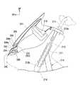
図1は、鞍乗り型車両の光学センサ配置構造の一例として、車両前方の物体等を撮影可能なカメラを備えたスポーツタイプの自動二輪車1のカメラ配置構造を示す。以下、自動二輪車1を単に「車両」ということがある。(First embodiment)
FIG. 1 shows, as an example of an optical sensor arrangement structure of a saddle-ride type vehicle, a camera arrangement structure of a sports type motorcycle 1 provided with a camera capable of photographing an object or the like in front of the vehicle. Hereinafter, the motorcycle 1 may be simply referred to as “vehicle”.
<光学センサ配置構造>
図1及び図2を併せて参照し、光学センサ配置構造2は、車体前部に配置された左右一対のカメラ30(光学センサ)と、車体フレーム10の前端のヘッドパイプ11(図2参照)の前方に配置されかつ車体前部を覆うとともに、走行風を後方へ導く導入口40が形成されたフロントカウル4(導風部材)と、フロントカウル4との間で走行風を導く導風路50を形成する吸気ダクト5(第二導風部材)と、を備えている。<Optical sensor arrangement structure>
Referring to FIGS. 1 and 2 together, the optical
<フロントカウル>
図1に示すように、フロントカウル4は、車体フレーム10の前上部を前方から左右側方にかけて覆うアッパーカウル41と、アッパーカウル41の左右両側に連なるとともに車体フレーム10の左右側方を覆う左右サイドカウル42と、を備えている。<Front cowl>
As shown in FIG. 1, the
アッパーカウル41の前部には、左右一対のヘッドライト43が配置されている。アッパーカウル41は、左右ヘッドライト43の上方を覆うアッパーセンタカウル44と、アッパーセンタカウル44の上方に延びるウインドスクリーン45と、左右サイドカウル42の上方で左右ヘッドライト43の左右側部を覆う左右アッパーサイドカウル46と、を備えている。 At the front of the
アッパーセンタカウル44には、左右一対のバックミラー12の取付座44aが形成されている。左右バックミラー12は、ミラー本体12aと、ミラー本体12aを保持する筐体12bと、筐体12bを支持するミラーステー12cと、を備えている。左右筐体12bの前部には、ウインカ12dが設けられている。左右ミラーステー12cの基端部は、アッパーセンタカウル44の取付座44aを貫通して、アッパーカウル41の内側に配置された不図示の支持ステーに締結固定されている。 The
左右アッパーサイドカウル46は、左右吸気ダクト5の左右側部を覆うように前後に延びている。左右アッパーサイドカウル46の前端部には、導入口40を形成するとともに、吸気ダクト5との間で導風路50を形成する導風壁部46aが設けられている。図1の前面視で、導風壁部46aは、車幅方向内側ほど下方に位置するように傾斜している。図3の断面視で、導風壁部46aは、車幅方向外側ほど後方に位置するように傾斜している。 The left and right
なお、図中符号14はステアリングステム13を介してヘッドパイプ11に操向可能に支持された左右フロントフォーク、図中符号15はステアリングステム13のトップブリッジ13a上に取り付けられたバータイプの操向ハンドル、図中符号13bはステアリングステム13のボトムブリッジ、図中符号16は各種計器及び情報表示部を備えたメーターユニット、図中符号17は左右カメラ30で撮影された画像等を表示可能なモニターパネルをそれぞれ示している。
<吸気ダクト>
図1及び図2を併せて参照し、車体フレーム10の左右側方には、左右一対の吸気ダクト5が配置されている。図1及び図3を併せて参照し、左右吸気ダクト5は、アッパーカウル41との間で導入口40から入り込んだ走行風を後方へ導く導風路50を形成している。左右吸気ダクト5は、前後方向に沿うように延びている。左右吸気ダクト5の後端部は、不図示のエアクリーナに接続されている。<Air intake duct>
With reference to FIGS. 1 and 2, a pair of left and
図2及び図3を併せて参照し、右側の吸気ダクト5は、車幅方向内側に配置されたダクト内壁5aと、ダクト内壁5aよりも車幅方向外側に配置されたダクト外壁5bと、を備えている。なお、左側の吸気ダクト5については、右側の吸気ダクト5と同様の構成を有するため、その詳細な説明を省略する。 2 and 3, the
図2の右側面視で、ダクト内壁5aは、右側のヘッドライト43の稜線43aと重なる位置から後下方に傾斜して延びた後に、後方に屈曲して延びている。図3の断面視で、ダクト内壁5aは、右側のカメラ30の右側部から右後方に傾斜して延びた後に、後方に向けて湾曲しつつ延びている。 When viewed from the right side in FIG. 2, the duct
図2の右側面視で、ダクト外壁5bは、右側のカメラ30よりも後方に離反した位置で上下に延びる前端縁からダクト内壁5aと重なるように後方に向けて延びている。図3の断面視で、ダクト外壁5bは、右側のアッパーサイドカウル46の内壁46b(具体的には、導風壁部46aの後端から車幅方向外方に延びる延出部)から後方に延びた後に、ダクト内壁5aと車幅方向に所定の間隔を開けるように後方に向けて湾曲しつつ延びている。 In the right side view of FIG. 2, the duct
このような構成により、フロントカウル4の導入口40から導入された走行風は、フロントカウル4と吸気ダクト5との間の導風路50を通過した後、吸気ダクト5内に導かれて(すなわち、ダクト内壁5aとダクト外壁5bとの間に入り込んで)、後方に向けて流れるようになっている。なお、図3中符号W1は、風の流れを示している。 With such a configuration, the traveling wind introduced from the
<カメラ>
図1及び図2を併せて参照し、車両は、カメラを用いた運転支援システム3を備えている。運転支援システム3は、車体左右中心線CLを挟んで左右対称位置に配置された左右一対のカメラ30を備えている。左右カメラ30は、車両前方の物体等を互いに異なる視点で撮影するステレオカメラを構成している。運転支援システム3は、左右カメラ30によって車両前方を撮影し、車両前方の物体等を検知可能になっている。<Camera>
Referring to FIG. 1 and FIG. 2 together, the vehicle includes a driving
左右カメラ30は、撮影した画像を、運転支援システム3の制御装置(不図示)における画像処理部に出力する。画像処理部は、左右カメラ30で撮影された画像をもとに、車両前方の他車を含む物体等の認識、及び対象物と車両との間の距離の演算等を行う。画像処理部は、制御装置の指令部に処理情報を出力する。指令部は、車両の衝突防止のためのブレーキ制御及び操舵制御等の運転支援、並びに乗員への各種警告等を行うための指令を車両各部に出力する。なお、運転支援システム3は、ナビゲーションシステム及びクルーズコントロールシステムと連係してもよい、左右カメラ30は、ドライブレコーダに利用してもよい。 The left and
図1に示すように、左右カメラ30は、前面視で左右フロントフォーク14よりも左右外側に配置されている。これにより、左右フロントフォーク14を挟んで左右カメラ30の車幅方向の距離を確保することができ、車両前方の対象物と自車両との距離等を精度良く計測することができる。 As shown in FIG. 1, the left and
左右カメラ30は、左右ヘッドライト43に近接して配置されている。これにより、夜間であっても車両前方を撮影しやすくなるため、車両前方の対象物の検知精度を高めることができる。 The left and
図1の前面視で、左右カメラ30は、導入口40と重なっている。図3及び図4を併せて参照し、カメラ30は、カメラ本体31と、カメラ本体31から車両前方に向けて突出するレンズ32と、を備えている。 In the front view of FIG. 1, the left and
カメラ本体31は、車幅方向外側から吸気ダクト5のダクト内壁5aで覆われている。すなわち、カメラ30は、吸気ダクト5の車幅方向内側に設けられている。図示はしないが、カメラ本体31は、ハーネスを介して制御装置及び電源ユニット等に接続されている。 The
レンズ32は、フロントカウル4と吸気ダクト5との境界部6に配置されている。図5の右側面視で、レンズ32は、フロントカウル4と重なっている。具体的に、図5の右側面視で、レンズ32は、右アッパーサイドカウル46と重なるとともに、右アッパーサイドカウル46よりも車幅方向内側に配置されている。図5の右側面視で、レンズ32は、下側ほど前方に位置するように傾斜する導風壁部46aの前端縁よりも後方に配置されている。図3に示すように、レンズ32は、導入口40よりも後方に配置されているので、目立ちにくい構造となっている。 The
レンズ32は、導入口40を通じて、車両前方に露出している。すなわち、カメラ30の前方には、カメラ30の視野を遮る部材等は配置されていない。これにより、カメラ30は、導入口40を通じて、車両前方を撮影可能となっている。 The
以上説明したように、上記実施形態は、カメラ30と、ヘッドパイプ11の前方に配置されかつ車体前部を覆うとともに、走行風を後方へ導く導入口40が形成されたフロントカウル4と、を備えた自動二輪車1の光学センサ配置構造2において、カメラ30は、前面視で導入口40と重なっているものである。
この構成によれば、カメラ30が前面視で導入口40と重なっていることで、カメラ30を正面に露呈した状態で目立ちにくい場所に配置することができる。つまり、カメラ30の検知領域(すなわち視野)が狭くなることを回避するとともに、外部からカメラ30が視認されにくくすることができる。したがって、カメラ30の検知領域を確保しつつ外観性を向上することができる。As described above, the above-described embodiment includes the
According to this configuration, since the
また、上記実施形態では、カメラ30が、フロントカウル4と吸気ダクト5との境界部6に配置されたレンズ32を備えていることで、カメラ30の検知領域が狭くなることを効果的に回避するとともに、外部からカメラ30がより一層視認されにくくすることができる。したがって、カメラ30の検知領域を効果的に確保しつつ外観性をより一層向上することができる。 Further, in the above-described embodiment, the
また、上記実施形態では、レンズ32が側面視でフロントカウル4と重なっていることで、側方からカメラ30が視認されにくくなるため、側方からの外観性をより一層向上することができる。 In addition, in the above embodiment, since the
また、上記実施形態では、カメラ30が吸気ダクト5の車幅方向内側に設けられていることで、カメラ30を吸気ダクト5の車幅方向外側に設けた場合と比較して、車体前部が車幅方向外側に大型化することを抑制することができるため、外観性をより一層向上することができる。 Further, in the above embodiment, since the
(第二実施形態)
図6〜図8に示すように、第二実施形態は、鞍乗り型車両の光学センサ配置構造の一例として、車両前方の物体等を撮影可能なカメラ230を備えたスクータタイプの自動二輪車201のカメラ配置構造を備えたものである。なお、以下の説明においては、上述した第一実施形態と同様の構成については同一の符号を付して説明を省略する。(Second embodiment)
As shown in FIGS. 6 to 8, the second embodiment is directed to a scooter-
<光学センサ配置構造>
図6及び図7を併せて参照し、光学センサ配置構造202は、車体前部に配置されたカメラ230(光学センサ)と、車体フレーム210の前端のヘッドパイプ211(図7参照)の前方に配置されかつ車体前部を覆うとともに、走行風を後方へ導く導入口240が形成されたガーニッシュ204(導風部材)と、ガーニッシュ204との間で走行風を導く導風路250を形成するメーターパネル205(第二導風部材)と、を備えている。<Optical sensor arrangement structure>
6 and 7, the optical
<ガーニッシュ>
ガーニッシュ204は、車体フレーム210の前上部を前方から左右側方にかけて覆うフロントカウル243に取り付けられている。図6の前面視で、ガーニッシュ204は、上側ほど車幅方向外方に広がるU字状をなしている。<Garnish>
The
ガーニッシュ204には、導入口240を形成するとともに、メーターパネル205との間で導風路250を形成する導風壁部204aと、外部に露出する外側部204bと、が設けられている。図8の断面視で、導風壁部204aは、後側ほど上方に位置するように傾斜している。図8の断面視で、外側部204bは、後側ほど上方に位置するように、導風壁部204aの傾斜よりも急峻に傾斜している。 The
図6及び図7を併せて参照し、ガーニッシュ204の上方には、メーターバイザー241が配置されている。ガーニッシュ204の下方には、ヘッドライト242が配置されている。図6の前面視で、ヘッドライト242は、ガーニッシュ204の下端縁に沿う上端縁を有するU字状をなしている。 Referring to FIGS. 6 and 7 together, a
なお、図中符号212は左右一対のバックミラー、図中符号214はステアリングステム213を介してヘッドパイプ211に操向可能に支持された左右フロントフォーク、図中符号215はステアリングステム213のトップブリッジ213a上に取り付けられたバータイプの操向ハンドル、図中符号213bはステアリングステム213のボトムブリッジ、図中符号216は各種計器及び情報表示部を備えたメーターユニットをそれぞれ示している。 In the figure,
<メーターパネル>
図7に示すように、メーターバイザー241の後方には、メーターパネル205が配置されている。メーターパネル205は、ガーニッシュ204との間で導入口240から入り込んだ走行風を後方へ導く導風路250を形成している。図7の断面視で、メーターパネル205は、メーターバイザー241と所定の間隔を開けつつ上側ほど後方に位置するように傾斜して延びている。<Meter panel>
As shown in FIG. 7, a
<カメラ>
車両は、カメラを用いた運転支援システム203を備えている。運転支援システム203は、図6の前面視で車体左右中心線CLと重なる位置に配置されたカメラ230を一つのみ備えている。運転支援システム203は、カメラ230によって車両前方を撮影し、車両前方の物体等を検知可能になっている。<Camera>
The vehicle includes a driving
カメラ230は、ボトムブリッジ213bよりも上方に配置されている。これにより、カメラ230に対する下方からの外乱をボトムブリッジ213bで抑制することができる。加えて、カメラ230をボトムブリッジ213bよりも下方に配置した場合と比較して、カメラ230の位置を高くすることができ、カメラ230の検知範囲における路面上方の空間が占める割合が大きくなるため、車両前方の検知精度を高めることができる。 The
カメラ230は、ヘッドライト242に近接して配置されている。これにより、夜間であっても車両前方を撮影しやすくなるため、車両前方の対象物の検知精度を高めることができる。 The
図6の前面視で、カメラ230は、導入口240と重なっている。図8に示すように、カメラ230は、カメラ本体231と、カメラ本体231から車両前方に向けて突出するレンズ232と、を備えている。 6, the
カメラ本体231は、ガーニッシュ204及びメーターパネル205で覆われている。すなわち、カメラ本体231は、外部に露出しないように設けられている。図示はしないが、カメラ本体231は、ハーネスを介して制御装置及び電源ユニット等に接続されている。 The
レンズ232は、ガーニッシュ204とメーターパネル205との境界部206に配置されている。図8の断面視で、境界部206は、後側ほど上方に位置するように傾斜する導風壁部204aの後端と、後側ほど上方に位置するように導風壁部204aの傾斜よりも急峻に傾斜するメーターパネル205の下端との間の部分である。境界部206は、ガーニッシュ204とメーターパネル205とで形成された後方に向けて窪む凹部207に設けられている。 The
レンズ232は、側面視でガーニッシュ204の外側部204bと重なっている。具体的に、図8の断面視で、レンズ232は、外側部204bと重なるとともに、外側部204b車幅方向内側に配置されている。図8の断面視で、レンズ232は、上側ほど後方に位置するように傾斜する外側204bの前端縁よりも後方に配置されている。図8に示すように、レンズ232は、導入口240よりも後方に配置されているので、目立ちにくい構造となっている。 The
メーターパネル205の下端及びメーターバイザー241の下端は、レンズ232よりも上方に位置している。ガーニッシュ204の導風壁部204aの後上端は、レンズ232よりも下方に位置している。 The lower end of the
レンズ232は、導入口240を通じて、車両前方に露出している。すなわち、カメラ230の前方には、カメラ230の視野を遮る部材等は配置されていない。これにより、カメラ230は、導入口240を通じて、車両前方を撮影可能となっている。 The
以上説明したように、上記実施形態は、カメラ230と、ヘッドパイプ211の前方に配置されかつ車体前部を覆うとともに、走行風を後方へ導く導入口240が形成されたガーニッシュ204と、を備えた自動二輪車201の光学センサ配置構造202において、カメラ230は、前面視で導入口240と重なっているものである。
この構成によれば、カメラ230が前面視で導入口240と重なっていることで、カメラ230を正面に露呈した状態で目立ちにくい場所に配置することができる。つまり、カメラ230の検知領域が狭くなることを回避するとともに、外部からカメラ230が視認されにくくすることができる。したがって、カメラ230の検知領域を確保しつつ外観性を向上することができる。As described above, the above-described embodiment includes the
According to this configuration, since the
また、上記実施形態では、カメラ230が、ガーニッシュ204とメーターパネル205との境界部206に配置されたレンズ232を備えていることで、カメラ230の検知領域が狭くなることを効果的に回避するとともに、外部からカメラ230がより一層視認されにくくすることができる。したがって、カメラ230の検知領域を効果的に確保しつつ外観性をより一層向上することができる。 In the above-described embodiment, the
また、上記実施形態では、境界部206がガーニッシュ204とメーターパネル205とで形成された凹部207に設けられていることで、ガーニッシュ204及びメーターパネル205をカメラ230の画角(視野角)に沿った形状とすることができる。したがって、カメラ230の検知領域をより一層効果的に確保しつつ外観性をより一層向上することができる。 Further, in the above-described embodiment, since the
また、上記実施形態では、レンズ232が側面視でガーニッシュ204と重なっていることで、側方からカメラ230が視認されにくくなるため、側方からの外観性をより一層向上することができる。 Further, in the above embodiment, since the
なお、本発明は上記実施形態に限られるものではなく、例えば、カメラは可視光のみならず赤外線等の不可視光を撮影するカメラであってもよい。カメラのみならず赤外線またはミリ波等を用いたレーダー等の光学センサであってもよい。左右一対ではなく単体の光学センサを用いる構成であってもよい。カメラおよびレーダーを併用する構成であってもよい。上記実施形態におけるカメラのレンズの配置は、レーダーの場合はアンテナの配置となる。
前記鞍乗り型車両には、運転者が車体を跨いで乗車する車両全般が含まれ、自動二輪車(原動機付自転車及びスクータ型車両を含む)のみならず、三輪(前一輪かつ後二輪の他に、前二輪かつ後一輪の車両も含む)又は四輪の車両も含まれる。
そして、上記実施形態における構成は本発明の一例であり、実施形態の構成要素を周知の構成要素に置き換える等、本発明の要旨を逸脱しない範囲で種々の変更が可能である。Note that the present invention is not limited to the above embodiment. For example, the camera may be a camera that captures not only visible light but also invisible light such as infrared light. Not only a camera but also an optical sensor such as a radar using infrared rays or millimeter waves may be used. A configuration using a single optical sensor instead of a pair of right and left may be used. A configuration using a camera and a radar together may be used. In the case of the radar, the arrangement of the camera lens in the above embodiment is the arrangement of the antenna.
The saddle-ride type vehicle includes all types of vehicles in which a driver rides across a vehicle body, and includes not only motorcycles (including motor-driven bicycles and scooter-type vehicles) but also three wheels (besides one front wheel and two rear wheels). , Front two-wheel and rear one-wheel vehicles) or four-wheel vehicles.
The configuration in the above embodiment is an example of the present invention, and various changes can be made without departing from the gist of the present invention, such as replacing the component of the embodiment with a known component.
1,201 自動二輪車(鞍乗り型車両)
2,202 光学センサ配置構造
4 フロントカウル(導風部材)
5 吸気ダクト(第二導風部材)
6,206 境界部
11,211 ヘッドパイプ
30,230 カメラ(光学センサ)
32,232 レンズ
40,240 導入口
50,250 導風路
204 ガーニッシュ(導風部材)
205 メーターパネル(第二導風部材)1,201 motorcycles (saddle-riding type vehicles)
2,202 Optical
5 Intake duct (second air guide member)
6,206 Boundary part 11,211 Head pipe 30,230 Camera (optical sensor)
32,232 Lens 40,240 Inlet port 50,250
205 Meter panel (second air guide member)
Claims (5)
Translated fromJapaneseヘッドパイプ(11,211)の前方に配置されかつ車体前部を覆うとともに、走行風を後方へ導く導入口(40,240)が形成された導風部材(4,204)と、を備えた鞍乗り型車両(1,201)の光学センサ配置構造(2,202)において、
前記光学センサ(30,230)は、前面視で前記導入口(40,240)と重なっていることを特徴とする鞍乗り型車両の光学センサ配置構造。An optical sensor (30, 230);
A wind guide member (4, 204) disposed in front of the head pipes (11, 211) and covering a front portion of the vehicle body, and formed with an inlet (40, 240) for guiding running wind backward. In the optical sensor arrangement structure (2,202) of the saddle type vehicle (1,201),
The optical sensor arrangement structure for a saddle-ride type vehicle, wherein the optical sensor (30, 230) overlaps the inlet (40, 240) when viewed from the front.
前記光学センサ(30,230)は、前記導風部材(4,204)と前記第二導風部材(5,205)との境界部(6,206)に配置されたレンズ(32,232)を備えていることを特徴とする請求項1に記載の鞍乗り型車両の光学センサ配置構造。A second air guide member (5, 205) for forming an air guide path (50, 250) for guiding the traveling wind with the air guide member (4, 204);
The optical sensor (30, 230) is a lens (32, 232) disposed at a boundary (6, 206) between the air guide member (4, 204) and the second air guide member (5, 205). The optical sensor arrangement structure for a saddle-ride type vehicle according to claim 1, further comprising:
Priority Applications (3)
| Application Number | Priority Date | Filing Date | Title |
|---|---|---|---|
| JP2016097421AJP6628411B2 (en) | 2016-05-13 | 2016-05-13 | Optical sensor arrangement structure for saddle type vehicle |
| US15/590,674US10166909B2 (en) | 2016-05-13 | 2017-05-09 | Optical sensor disposition structure for saddle riding vehicle |
| EP17170231.9AEP3243731B1 (en) | 2016-05-13 | 2017-05-09 | Optical sensor disposition structure for saddle riding vehicle |
Applications Claiming Priority (1)
| Application Number | Priority Date | Filing Date | Title |
|---|---|---|---|
| JP2016097421AJP6628411B2 (en) | 2016-05-13 | 2016-05-13 | Optical sensor arrangement structure for saddle type vehicle |
Publications (2)
| Publication Number | Publication Date |
|---|---|
| JP2017202810A JP2017202810A (en) | 2017-11-16 |
| JP6628411B2true JP6628411B2 (en) | 2020-01-08 |
Family
ID=58701446
Family Applications (1)
| Application Number | Title | Priority Date | Filing Date |
|---|---|---|---|
| JP2016097421AActiveJP6628411B2 (en) | 2016-05-13 | 2016-05-13 | Optical sensor arrangement structure for saddle type vehicle |
Country Status (3)
| Country | Link |
|---|---|
| US (1) | US10166909B2 (en) |
| EP (1) | EP3243731B1 (en) |
| JP (1) | JP6628411B2 (en) |
Families Citing this family (18)
| Publication number | Priority date | Publication date | Assignee | Title |
|---|---|---|---|---|
| US10144473B2 (en)* | 2013-11-15 | 2018-12-04 | Kawasaki Jukogyo Kabushiki Kaisha | Straddle-type vehicle |
| US10562477B2 (en)* | 2016-06-24 | 2020-02-18 | Honda Motor Co., Ltd. | Optical sensor supporting structure for saddled vehicle |
| JP6848312B2 (en)* | 2016-09-30 | 2021-03-24 | スズキ株式会社 | Wind guide structure for saddle-mounted vehicles |
| DE112018007340T5 (en) | 2018-03-23 | 2020-12-10 | Honda Motor Co., Ltd. | Straddle seat vehicle |
| JP6967659B2 (en)* | 2018-03-23 | 2021-11-17 | 本田技研工業株式会社 | Saddle-type vehicle |
| JP6978587B2 (en)* | 2018-03-29 | 2021-12-08 | 本田技研工業株式会社 | Saddle-type vehicle |
| CN112105551B (en) | 2018-05-23 | 2022-04-26 | 本田技研工业株式会社 | Saddle-ride type vehicle |
| JP6982173B2 (en)* | 2018-05-23 | 2021-12-17 | 本田技研工業株式会社 | Saddle-type vehicle |
| JP7198602B2 (en) | 2018-07-11 | 2023-01-04 | カワサキモータース株式会社 | motorcycle |
| JP7046783B2 (en)* | 2018-11-16 | 2022-04-04 | 本田技研工業株式会社 | Saddle-type vehicle |
| JP6865728B2 (en)* | 2018-12-21 | 2021-04-28 | 川崎重工業株式会社 | Saddle-type vehicle |
| AT522637A1 (en)* | 2019-05-29 | 2020-12-15 | Ktm Ag | Headlight with sensor |
| JP7481839B2 (en)* | 2019-12-19 | 2024-05-13 | カワサキモータース株式会社 | Saddle type vehicle |
| JP7192003B2 (en)* | 2020-03-27 | 2022-12-19 | 本田技研工業株式会社 | Body cover structure of saddle type vehicle |
| CN116685863A (en)* | 2021-02-05 | 2023-09-01 | 日立安斯泰莫株式会社 | Object detection device |
| EP4063193A1 (en)* | 2021-03-24 | 2022-09-28 | ZKW Group GmbH | Motor vehicle headlamp |
| JP7685045B2 (en)* | 2021-05-13 | 2025-05-28 | Astemo株式会社 | Mounting device and mounting method |
| WO2025100011A1 (en)* | 2023-11-06 | 2025-05-15 | 日立Astemo株式会社 | Camera arrangement structure for saddle-ridden vehicle |
Family Cites Families (13)
| Publication number | Priority date | Publication date | Assignee | Title |
|---|---|---|---|---|
| US5725709A (en)* | 1995-10-13 | 1998-03-10 | Lockheed Missiles & Space Co., Inc. | Fabrication method for an inflatable deployable control structure for aerospace vehicles |
| JP2004175126A (en)* | 2002-11-22 | 2004-06-24 | Suzuki Motor Corp | Camera device to be mounted on motorcycle |
| JP2006103600A (en) | 2004-10-07 | 2006-04-20 | Yamaha Motor Co Ltd | Forward visual confirmation device of motorcycle |
| IL165190A (en)* | 2004-11-14 | 2012-05-31 | Elbit Systems Ltd | System and method for stabilizing an image |
| JP2008189179A (en)* | 2007-02-06 | 2008-08-21 | Honda Motor Co Ltd | Cold air system for saddle-ride type vehicles |
| JP4766402B2 (en)* | 2008-10-21 | 2011-09-07 | トヨタ自動車株式会社 | Radar equipment |
| ES2356218B1 (en) | 2009-08-25 | 2012-02-29 | Julián Del Castillo Díaz | IMPROVED VISION SYSTEM FOR MOTORCYCLE COMPANIONS. |
| JP5988639B2 (en)* | 2012-03-22 | 2016-09-07 | 本田技研工業株式会社 | Wind guide structure for saddle-ride type vehicles |
| RU2582478C1 (en)* | 2012-07-27 | 2016-04-27 | Ниссан Мотор Ко., Лтд. | Vehicle-mounted camera device |
| JP5864483B2 (en) | 2013-07-10 | 2016-02-17 | 本田技研工業株式会社 | Front structure of saddle-ride type vehicle |
| US9366546B2 (en)* | 2014-02-24 | 2016-06-14 | Lockheed Martin Corporation | Projected synthetic vision |
| WO2015191512A1 (en)* | 2014-06-11 | 2015-12-17 | Trw Automotive Us Llc | Moderation of a driver assist camera environment by headliner air duct |
| GB201416016D0 (en)* | 2014-09-10 | 2014-10-22 | Hamilton Anthony C | Infomation Display Module |
- 2016
- 2016-05-13JPJP2016097421Apatent/JP6628411B2/enactiveActive
- 2017
- 2017-05-09USUS15/590,674patent/US10166909B2/ennot_activeExpired - Fee Related
- 2017-05-09EPEP17170231.9Apatent/EP3243731B1/enactiveActive
Also Published As
| Publication number | Publication date |
|---|---|
| EP3243731A1 (en) | 2017-11-15 |
| US20170327026A1 (en) | 2017-11-16 |
| US10166909B2 (en) | 2019-01-01 |
| EP3243731B1 (en) | 2018-12-12 |
| JP2017202810A (en) | 2017-11-16 |
Similar Documents
| Publication | Publication Date | Title |
|---|---|---|
| JP6628411B2 (en) | Optical sensor arrangement structure for saddle type vehicle | |
| US10562477B2 (en) | Optical sensor supporting structure for saddled vehicle | |
| JP6543823B2 (en) | Optical sensor arrangement structure of straddle type vehicle | |
| JP6550670B2 (en) | Saddle-ride type vehicle | |
| JP2009023543A (en) | Vehicle and vehicle driving support device | |
| EP2762892B1 (en) | Vehicle speed calculator | |
| EP3508406B1 (en) | Saddle-type vehicle | |
| CN113443051B (en) | Straddle-type vehicle and control device | |
| JP2018144799A (en) | Saddle-type vehicle lighting device arrangement structure and saddle-ride type vehicle | |
| JP7502479B2 (en) | Saddle-ride type vehicle, information processing device, and information processing method | |
| EP2762394B1 (en) | Motorcycle | |
| US10379343B2 (en) | Saddle riding vehicle | |
| JP7000851B2 (en) | Driving support device | |
| KR101679865B1 (en) | Support system for driving vehicle | |
| WO2025100011A1 (en) | Camera arrangement structure for saddle-ridden vehicle | |
| JP2013164926A (en) | Lamp system and vehicle lamp | |
| CN107054532B (en) | Vehicle |
Legal Events
| Date | Code | Title | Description |
|---|---|---|---|
| RD03 | Notification of appointment of power of attorney | Free format text:JAPANESE INTERMEDIATE CODE: A7423 Effective date:20181005 | |
| A621 | Written request for application examination | Free format text:JAPANESE INTERMEDIATE CODE: A621 Effective date:20181127 | |
| A977 | Report on retrieval | Free format text:JAPANESE INTERMEDIATE CODE: A971007 Effective date:20191010 | |
| TRDD | Decision of grant or rejection written | ||
| A01 | Written decision to grant a patent or to grant a registration (utility model) | Free format text:JAPANESE INTERMEDIATE CODE: A01 Effective date:20191105 | |
| A61 | First payment of annual fees (during grant procedure) | Free format text:JAPANESE INTERMEDIATE CODE: A61 Effective date:20191202 | |
| R150 | Certificate of patent or registration of utility model | Ref document number:6628411 Country of ref document:JP Free format text:JAPANESE INTERMEDIATE CODE: R150 |