JP6628189B2 - Detection device and detection method - Google Patents
Detection device and detection methodDownload PDFInfo
- Publication number
- JP6628189B2 JP6628189B2JP2016100674AJP2016100674AJP6628189B2JP 6628189 B2JP6628189 B2JP 6628189B2JP 2016100674 AJP2016100674 AJP 2016100674AJP 2016100674 AJP2016100674 AJP 2016100674AJP 6628189 B2JP6628189 B2JP 6628189B2
- Authority
- JP
- Japan
- Prior art keywords
- pedestrian crossing
- candidate position
- estimated
- unit
- vehicle
- Prior art date
- Legal status (The legal status is an assumption and is not a legal conclusion. Google has not performed a legal analysis and makes no representation as to the accuracy of the status listed.)
- Expired - Fee Related
Links
Images


Classifications
- G—PHYSICS
- G06—COMPUTING OR CALCULATING; COUNTING
- G06V—IMAGE OR VIDEO RECOGNITION OR UNDERSTANDING
- G06V20/00—Scenes; Scene-specific elements
- G06V20/50—Context or environment of the image
- G06V20/56—Context or environment of the image exterior to a vehicle by using sensors mounted on the vehicle
- G06V20/588—Recognition of the road, e.g. of lane markings; Recognition of the vehicle driving pattern in relation to the road
- G—PHYSICS
- G01—MEASURING; TESTING
- G01S—RADIO DIRECTION-FINDING; RADIO NAVIGATION; DETERMINING DISTANCE OR VELOCITY BY USE OF RADIO WAVES; LOCATING OR PRESENCE-DETECTING BY USE OF THE REFLECTION OR RERADIATION OF RADIO WAVES; ANALOGOUS ARRANGEMENTS USING OTHER WAVES
- G01S13/00—Systems using the reflection or reradiation of radio waves, e.g. radar systems; Analogous systems using reflection or reradiation of waves whose nature or wavelength is irrelevant or unspecified
- G01S13/02—Systems using reflection of radio waves, e.g. primary radar systems; Analogous systems
- G01S13/04—Systems determining presence of a target
- G—PHYSICS
- G01—MEASURING; TESTING
- G01S—RADIO DIRECTION-FINDING; RADIO NAVIGATION; DETERMINING DISTANCE OR VELOCITY BY USE OF RADIO WAVES; LOCATING OR PRESENCE-DETECTING BY USE OF THE REFLECTION OR RERADIATION OF RADIO WAVES; ANALOGOUS ARRANGEMENTS USING OTHER WAVES
- G01S13/00—Systems using the reflection or reradiation of radio waves, e.g. radar systems; Analogous systems using reflection or reradiation of waves whose nature or wavelength is irrelevant or unspecified
- G01S13/88—Radar or analogous systems specially adapted for specific applications
- G01S13/93—Radar or analogous systems specially adapted for specific applications for anti-collision purposes
- G01S13/931—Radar or analogous systems specially adapted for specific applications for anti-collision purposes of land vehicles
- G—PHYSICS
- G08—SIGNALLING
- G08G—TRAFFIC CONTROL SYSTEMS
- G08G1/00—Traffic control systems for road vehicles
- G08G1/16—Anti-collision systems
- G08G1/166—Anti-collision systems for active traffic, e.g. moving vehicles, pedestrians, bikes
- G—PHYSICS
- G01—MEASURING; TESTING
- G01S—RADIO DIRECTION-FINDING; RADIO NAVIGATION; DETERMINING DISTANCE OR VELOCITY BY USE OF RADIO WAVES; LOCATING OR PRESENCE-DETECTING BY USE OF THE REFLECTION OR RERADIATION OF RADIO WAVES; ANALOGOUS ARRANGEMENTS USING OTHER WAVES
- G01S13/00—Systems using the reflection or reradiation of radio waves, e.g. radar systems; Analogous systems using reflection or reradiation of waves whose nature or wavelength is irrelevant or unspecified
- G01S13/88—Radar or analogous systems specially adapted for specific applications
- G01S13/93—Radar or analogous systems specially adapted for specific applications for anti-collision purposes
- G01S13/931—Radar or analogous systems specially adapted for specific applications for anti-collision purposes of land vehicles
- G01S2013/9327—Sensor installation details
- G01S2013/93271—Sensor installation details in the front of the vehicles
Landscapes
- Engineering & Computer Science (AREA)
- Physics & Mathematics (AREA)
- Radar, Positioning & Navigation (AREA)
- Remote Sensing (AREA)
- General Physics & Mathematics (AREA)
- Multimedia (AREA)
- Theoretical Computer Science (AREA)
- Computer Networks & Wireless Communication (AREA)
- Electromagnetism (AREA)
- Traffic Control Systems (AREA)
- Image Analysis (AREA)
Description
Translated fromJapanese本開示は、車両に搭載され、車両が走行する路面上の横断歩道を検出する検出装置および検出方法に関する。 The present disclosure relates to a detection device and a detection method mounted on a vehicle for detecting a pedestrian crossing on a road surface on which the vehicle runs.
近年、カメラ、ソナー、レーダ(例えば、ミリ波レーダ)等を用いて車両の周辺の物体(例えば、車両又は歩行者)を検出することにより、物体への衝突を回避するために車両を減速させる自動ブレーキシステムや運転者に物体への衝突の可能性を通知する警報システムが普及している。これらのシステムの普及は、単路を走行する車両の事故防止に貢献している。 In recent years, by detecting an object (for example, a vehicle or a pedestrian) around a vehicle using a camera, a sonar, a radar (for example, a millimeter-wave radar), the vehicle is decelerated to avoid a collision with the object. 2. Description of the Related Art Automatic brake systems and alarm systems that notify a driver of a possibility of collision with an object have become widespread. The spread of these systems has contributed to the prevention of accidents in vehicles traveling on a single road.
これらのシステムでは、誤動作を低減し、性能向上を図るために、システムが動作する条件を様々なセンサを用いて限定している。 In these systems, the conditions under which the system operates are limited using various sensors in order to reduce malfunctions and improve performance.
例えば、様々なセンサを用いて路面上の横断歩道を認識し、認識した横断歩道の周辺の歩行者や自転車を検出するように動作条件を限定、または、優先することによって、システムの性能向上を図ることができる。そのため、横断歩道を精度良く検出することにより、システムの性能向上が期待できる。 For example, system performance can be improved by recognizing a pedestrian crossing on the road surface using various sensors and limiting or giving priority to operating conditions to detect pedestrians and bicycles around the recognized pedestrian crossing. Can be planned. Therefore, by accurately detecting the pedestrian crossing, the performance of the system can be expected to improve.
特許文献1には、車両に搭載された単眼カメラを用いて、横断歩道の縞(周期的に配置された白線)に対応する輝度の強弱の変化を水平方向と垂直方向とで認識することにより、横断歩道を検出する装置が開示されている。
しかしながら、特許文献1に記載の技術は、交差点に進入した車両から右左折方向に存在する横断歩道を車両に搭載されたカメラによって撮影する場合、右左折方向に存在する横断歩道の縞の間隔は狭く映ってしまうため、高解像度カメラを用いて横断歩道の縞模様に対応する輝度の強弱の変化を認識しなければならず、高負荷な信号処理を行なわなければならない。 However, in the technology described in
本開示の非限定的な実施例は、信号処理の負荷の増大を防ぎ、短時間で横断歩道の位置を検出できる検出装置および検出方法を提供する。 A non-limiting embodiment of the present disclosure provides a detection device and a detection method that can prevent an increase in signal processing load and can detect the position of a pedestrian crossing in a short time.
本開示の一態様は、方位−距離センサの出力データに基づいて、車両の進行方向における横断歩道の候補位置を推定し、前記候補位置を用いて、前記横断歩道の長さと、前記横断歩道と車道との交差角度とを推定する位置推定部と、前記推定された横断歩道の長さおよび前記推定された交差角度に基づき、前記横断歩道の白線の間隔を示す、互いに直交する2つの基底関数の周期数および幅を補正する補正部と、前記候補位置を含む画像データと前記補正した2つの基底関数とを用いて、前記横断歩道の存在の有無を検出する横断歩道検出部と、を備える検出装置である。 One embodiment of the present disclosure is based on the output data of the direction-distance sensor, estimates a candidate position of a pedestrian crossing in the traveling direction of the vehicle, and uses the candidate position to determine a length of the pedestrian crossing and the pedestrian crossing. A position estimating unit for estimating an intersection angle with a roadway, and two basis functions orthogonal to each other indicating an interval between white lines of the pedestrian crossing based on the estimated length of the pedestrian crossing and the estimated intersection angle. A correction unit that corrects the number of cycles and width of the pedestrian crossing, and a pedestrian crossing detection unit that detects the presence or absence of the pedestrian crossing using the image data including the candidate position and the corrected two basis functions. It is a detection device.
本開示の一態様は、方位−距離センサの出力データに基づいて、車両の進行方向における横断歩道の候補位置を推定し、前記候補位置を用いて、前記横断歩道の長さと、前記横断歩道と車道との交差角度とを推定し、前記推定された横断歩道の長さおよび前記推定された交差角度に基づき、前記横断歩道の白線の間隔を示す、互いに直交する2つの基底関数の周期数および幅を補正し、前記候補位置を含む画像データと前記補正した2つの基底関数とを用いて、前記横断歩道の存在の有無を検出する、検出方法である。 One embodiment of the present disclosure is based on the output data of the direction-distance sensor, estimates a candidate position of a pedestrian crossing in the traveling direction of the vehicle, and uses the candidate position to determine a length of the pedestrian crossing and the pedestrian crossing. Estimating the intersection angle with the roadway, and based on the estimated crosswalk length and the estimated intersection angle, the number of periods of two basis functions orthogonal to each other, indicating the interval between the white lines of the crosswalk, and A detection method that corrects a width and detects the presence or absence of the crosswalk using image data including the candidate position and the corrected two basis functions.
なお、これらの包括的または具体的な態様は、システム、集積回路、コンピュータプログラム、または、記録媒体で実現されてもよく、システム、装置、方法、集積回路、コンピュータプログラムおよび記録媒体の任意な組み合わせで実現されてもよい。 Note that these comprehensive or specific aspects may be realized by a system, an integrated circuit, a computer program, or a recording medium, and any combination of a system, an apparatus, a method, an integrated circuit, a computer program, and a recording medium. May be realized.
本開示の一態様によれば、信号処理の負荷の増大を防ぎ、短時間で横断歩道の位置を検出できる。 According to an aspect of the present disclosure, it is possible to prevent an increase in a load of signal processing and detect a position of a pedestrian crossing in a short time.
本開示の一態様における更なる利点および効果は、明細書および図面から明らかにされる。かかる利点および/または効果は、いくつかの実施形態並びに明細書および図面に記載された特徴によってそれぞれ提供されるが、1つまたはそれ以上の同一の特徴を得るために必ずしも全てが提供される必要はない。 Further advantages and advantages of one aspect of the present disclosure will be apparent from the description and drawings. Such advantages and / or advantages are each provided by some embodiments and by the features described in the specification and drawings, but not necessarily all to achieve one or more identical features. There is no.
(本開示に至る経緯)
まず、本開示に至る経緯について説明する。本開示は、車両に搭載され、車両が走行する路面上の横断歩道を検出する検出装置および検出方法に関する。(History leading to the present disclosure)
First, the process leading to the present disclosure will be described. The present disclosure relates to a detection device and a detection method that are mounted on a vehicle and detect a crosswalk on a road surface on which the vehicle runs.
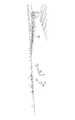
図1は、交差点における車両の前方の視界の一例を示す図である。図1には、車両の直進方向(矢印V1)に存在する横断歩道C1と車両の右折方向(矢印V2)に存在する横断歩道C2が示されている。特許文献1に記載の技術では、車両に搭載されたカメラによって図1に示すような画像を撮影し、横断歩道の縞に対応する輝度の強弱の変化を認識することによって、その画像における横断歩道の位置を検出する。 FIG. 1 is a diagram illustrating an example of a field of view ahead of a vehicle at an intersection. FIG. 1 shows a pedestrian crossing C1 existing in the vehicle straight ahead direction (arrow V1) and a pedestrian crossing C2 existing in the vehicle right turning direction (arrow V2). In the technology described in
横断歩道C1の縞の間隔は比較的広いため、図1に示す画像から横断歩道C1の縞に対応する輝度の強弱の変化を認識しやすい。 Since the intervals between the stripes of the pedestrian crossing C1 are relatively wide, it is easy to recognize a change in the intensity of the brightness corresponding to the stripes of the pedestrian crossing C1 from the image shown in FIG.
横断歩道C2は、車両の進行方向の正面ではなく、斜め前に存在するため、縞の間隔が横断歩道C1と比較して狭くなる。そのため、高解像度のカメラを用いて撮影を行なわなければ、図1に示す画像から横断歩道C2の縞に対応する輝度の強弱の変化を認識することが困難である。また、高解像度のカメラを用いると、処理すべきデータの量が増えてしまい、信号処理の負荷が増大してしまうため、横断歩道を検出するまでに時間の増加、回路規模の増加が発生してしまう。 Since the pedestrian crossing C2 exists diagonally forward rather than in front of the traveling direction of the vehicle, the interval between the stripes is narrower than that of the pedestrian crossing C1. Therefore, it is difficult to recognize a change in the intensity of the brightness corresponding to the stripes of the pedestrian crossing C2 from the image shown in FIG. 1 unless shooting is performed using a high-resolution camera. Also, if a high-resolution camera is used, the amount of data to be processed increases, and the load of signal processing increases, so that the time required to detect a pedestrian crossing and the circuit scale increase. Would.
このため、まず、レーダ装置によって、横断歩道の存在する位置及び道路形状を推定して、推定結果によって、カメラにより撮影される横断歩道の変形状態を推定することによって、カメラにより撮影された横断歩道の検出処理量を軽減する。 Therefore, first, the position and the road shape where the pedestrian crossing is located are estimated by the radar device, and the deformation state of the pedestrian crossing captured by the camera is estimated based on the estimation result. To reduce the detection processing amount.
このような事情に鑑み、まず、レーダ装置によって、横断歩道の存在する位置及び道路形状を推定して、推定結果によって、カメラにより撮影される横断歩道の変形状態を推定することによって(空間周波数を解析)、カメラにより撮影された横断歩道の検出処理量を軽減できることに着目し、本開示に至った。 In view of such circumstances, first, the position where the pedestrian crossing is located and the road shape are estimated by the radar device, and the deformation state of the pedestrian crossing photographed by the camera is estimated based on the estimation result (the spatial frequency is estimated as follows). Analysis), the present disclosure has been made by focusing on the fact that the detection processing amount of a pedestrian crossing photographed by a camera can be reduced.
以下、本開示の実施の形態について、図面を参照して詳細に説明する。なお、以下に説明する実施の形態は一例であり、本開示は以下の実施の形態により限定されるものではない。 Hereinafter, embodiments of the present disclosure will be described in detail with reference to the drawings. The embodiments described below are merely examples, and the present disclosure is not limited to the following embodiments.
(実施の形態)
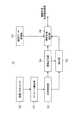
図2は、本実施の形態に係る検出装置10の構成の一例を示すブロック図である。検出装置10は、車両に搭載され、車両の周辺(例えば、前方、側方等の車両の進行方向)に存在する横断歩道を検出する。図2に示すように、検出装置10は、距離−方位センサ100、フリースペース検出部101、位置推定部102、画像データ取得部103、座標計算部104、補正部105、および、横断歩道検出部106を備える。(Embodiment)
FIG. 2 is a block diagram illustrating an example of a configuration of the
距離−方位センサ100は、車両の各方位に対して電波を送信し、車両の周辺に存在する物体によって反射された電波を反射波として受信する。そして、距離−方位センサ100は、受信した反射波に基づいて反射点を検出し、検出した反射点を示す反射点情報を、フレーム毎に生成する。フレームとは、距離−方位センサ100における処理単位である。 The distance-
例えば、距離−方位センサ100は、距離−方位センサ100からの電波の送信方向、および、距離−方位センサ100からの距離を所定の間隔で区切ったセル毎に、反射波の受信電力の代表値(以下、「反射強度」と云う)を測定する。そして、距離−方位センサ100は、所定の閾値以上の反射強度を有するセルを、反射点として検出する。そして、距離−方位センサ100は、反射点に基づき、車両から物体までの距離、物体の方向、および、車両の速度に対する物体の相対速度を検出する。距離−方位センサ100は、検出した情報を反射点情報として、フレーム毎に、フリースペース検出部101へ出力する。 For example, the distance-
フリースペース検出部101は、反射点情報を用いて、車両周辺における物体が存在しない領域との境界を、フレーム毎に検出する。車両周辺における物体が存在しない領域とは、車両が走行する領域、すなわち、車道領域である。つまり、フリースペース検出部101が検出する境界は、車道と車道外との間の境界である。 The free
具体的には、フリースペース検出部101は、距離−方位センサ100の検出範囲内の各方位において距離−方位センサ100からの距離が最も近い反射点の位置を、各方位における境界の点として、フレーム毎に検出する。 Specifically, the free
また、フリースペース検出部101は、過去のフレームにおいて検出した境界を、現フレームにおける境界へ変換する変換処理、および、過去のフレームにおいて検出した境界と、現フレームにおける境界とのスムージング処理を行う。 Further, the free
フリースペース検出部101は、変換処理およびスムージング処理を行った後の、現フレームの境界をフリースペース情報として位置推定部102へ出力する。なお、現フレームの境界は、距離−方位センサ100の検出範囲の座標平面と同一の座標平面の座標によって示される。例えば、距離−方位センサ100の検出範囲の座標平面(以下、T0座標平面)は、車両が走行する路面と略平行なX−Y平面である。 The free
なお、フリースペース検出部101の詳細については、特願2015−198675を参照されたい。 For details of the free
位置推定部102は、方位−距離センサ100の出力データに基づいて、車両の進行方向における横断歩道が存在する候補となる位置(以下、横断歩道の候補位置)を推定する。そして、位置推定部102は、推定した横断歩道の候補位置を用いて、横断歩道の長さと、横断歩道と車道との交差角度とを推定する。具体的には、位置推定部102は、フリースペース検出部101から取得する現フレームの境界に基づく複数の1次近似線を作成し、1次近似線から横断歩道が存在する候補となる位置(以下、横断歩道の候補位置)を推定し、横断歩道の候補位置を用いて、横断歩道の長さと、横断歩道と車道との交差角度と推定する。位置推定部102は、推定結果を座標計算部104および補正部105へ出力する。位置推定部102における横断歩道の候補位置を推定する方法については、後述するが、概略は、以下の通りである。 The
交差点などの複数の道路が交差する部分では、道路の縁の角が隅切り(丸く角が除去)されている。隅切りの大きさは、歩道の幅員等で決定される。隅切りの目的の1つは、運転者が大きなハンドル操作を行なわずに、スムーズに車両を右左折させるためである。また、隅切りの他の目的は、歩行者が右左折先の横断歩道を横断している場合、車両が右左折するために横断歩道の手前にて一時停止しても、直進する後続車両の妨げにならないようにするためである。つまり、交差点などの複数の道路が交差する部分において、隅切りは、右左折しようとする車両の進行方向から見て、横断歩道の手前側に設けられる。 At a portion where a plurality of roads intersect, such as an intersection, corners of road edges are cut off (rounded corners are removed). The size of the corner cut is determined by the width of the sidewalk or the like. One of the purposes of corner cutting is to make the vehicle turn right and left smoothly without a large steering wheel operation by the driver. Another purpose of corner cutting is that if a pedestrian is crossing the pedestrian crossing at the right or left turn, even if the vehicle stops right before the pedestrian crossing to make a right or left turn, This is so as not to hinder. That is, in a portion where a plurality of roads intersect, such as an intersection, the corner cut is provided on the near side of the pedestrian crossing when viewed from the traveling direction of the vehicle that is going to turn right or left.
そのため、本実施の形態における位置推定部102は、1次近似線の傾きが変化する箇所を横断歩道の手前側に設けられる隅切りの位置に対応する箇所とし、1次近似線の傾きが変化する箇所に基づいて、横断歩道の候補位置の座標P1、P3を推定する(図3A参照)。 For this reason, the
また、直角に交差する交差点の横断歩道は、歩行者が安全に車道を横断するために、車道に対して直角に設けられている。これは、歩行者の横断時間を短縮し、信号の待ち時間への配慮という目的もある。一方で、直角に交差していない交差点では、横断歩道を車道に対して直角に設けると、歩行者は横断歩道を横断するために迂回しなければならない。さらに、歩行者が迂回を避けるために横断歩道外を横断する可能性があるため、交通安全上問題がある。そのため、直角に交差していない交差点の横断歩道は、車道に直角ではなく、交差点の交差角度に応じて傾斜して設けられている。 Also, the pedestrian crossing at an intersection that crosses at right angles is provided at right angles to the road so that pedestrians can safely cross the road. This also has the purpose of reducing the pedestrian's traversing time and taking into account the waiting time for traffic lights. On the other hand, at an intersection that does not intersect at a right angle, if the pedestrian crossing is provided at right angles to the roadway, the pedestrian must detour to cross the pedestrian crossing. In addition, there is a traffic safety problem because pedestrians may cross the pedestrian crossing to avoid detours. Therefore, the pedestrian crossing at an intersection that does not intersect at a right angle is provided not at right angles to the roadway but at an angle in accordance with the intersection angle of the intersection.
そのため、位置推定部102は、1次近似線の傾きを用いて右折先の車道の交差角度θを算出することにより、横断歩道の角度を算出する。 Therefore, the
画像データ取得部103は、車両の前方に設けられ、車両の前方および前側方を撮影する単眼カメラ(図示せず)から画像データを取得する。画像データ取得部103は、画像データを横断歩道検出部106へ出力する。画像データは、例えば、単眼カメラの向きおよび画角によって予め定まる平面(以下、カメラ座標平面)におけるデータである。 The image
座標計算部104は、位置推定部102から取得する横断歩道の候補位置に対して座標変換を行う。具体的には、座標計算部104は、横断歩道検出部106における横断歩道の候補位置と画像データとを用いた処理のために、T0座標平面における横断歩道の候補位置を、カメラ座標平面における座標に変換する。なお、座標計算部104における座標変換は、周知の座標変換処理を用いて実行される。座標計算部104は、カメラ座標平面に変換した後の横断歩道の候補位置を、補正部105および横断歩道検出部106へ出力する。 The coordinate
補正部105は、横断歩道の検出における基準となる2つの基底関数を有する。2つの基底関数は、横断歩道の白線の間隔を示し、互いに直交する。補正部105は、T0座標平面における横断歩道の候補位置が示す横断歩道の長さ、角度、および、カメラ座標平面に変換した後の横断歩道の候補位置が示す横断歩道の長さ、角度に応じて2つの基底関数の周期数および幅を補正する。補正部105は、補正した後の2つの基底関数を横断歩道検出部106へ出力する。なお、補正部105における基底関数の補正処理については、後述する。 The
横断歩道検出部106は、横断歩道の候補位置を含む画像データと補正した2つの基底関数とを用いて、横断歩道の存在の有無を検出する。具体的には、横断歩道検出部106は、画像データ取得部103から取得する画像データから、座標計算部104から取得する横断歩道の候補位置に対応する範囲を部分データとして抽出する。そして、横断歩道検出部106は、抽出した部分データと、補正部105から取得する2つの基底関数それぞれとを用いて、部分データ内に、横断歩道の縞に対応する輝度の周期的な変化の存在を判定するための空間周波数解析を行う。 The pedestrian
横断歩道検出部106は、空間周波数解析として、抽出した部分データと、補正部105から取得する2つの基底関数それぞれとの内積を算出する。そして、横断歩道検出部106は、内積が所定の閾値以上の場合に、横断歩道が存在すると判定する。 The pedestrian
横断歩道検出部106は、横断歩道の位置を示す判定結果を、例えば、図示しない衝突防止装置等へ出力する。あるいは、横断歩道検出部106は、横断歩道の位置を示す判定結果を、例えば、図示しない表示部等に表示させることにより、運転者への注意を促す。なお、横断歩道検出部106における横断歩道の検出処理については、後述する。 The
次に、位置推定部102における横断歩道の候補位置を推定する方法について説明する。 Next, a method of estimating a candidate position of a pedestrian crossing in the
図3Aは、本実施の形態における横断歩道の候補位置の推定方法の一例を示す図である。図3Aは、検出装置10を備える車両Zが、図3Aの下方から交差点に進入して右折する状況における、右折する方向に存在する横断歩道を検出する例を示している。また、図3Aには、フリースペース検出部101によって検出された境界L1〜L4、および、時点T0〜T3それぞれにおける車両Zの状態が示されている。なお、境界L1〜L4の内側が車道である。 FIG. 3A is a diagram illustrating an example of a method for estimating a candidate position of a pedestrian crossing in the present embodiment. FIG. 3A illustrates an example in which a vehicle Z including the
位置推定部102は、横断歩道の候補位置として、図3Aに示す横断歩道を囲む4点の座標P1〜P4を推定する。また、位置推定部102は、横断歩道の長さW2、交差点を形成する2つの道路の交差角度θ、および、横断歩道が設けられた車道の道路幅W2’を推定する。 The
時点T0の車両Zは、直進している状態である。車両Zの運転者は、方向指示器を操作し、時点T0以降において右折を開始する。その際、検出装置10は、右折先に存在する横断歩道の位置の検出を開始する。そして、検出装置10は、時点T1までに、横断歩道の位置の検出を完了する。 The vehicle Z at the time point T0 is in a state of traveling straight. The driver of the vehicle Z operates the direction indicator, and starts turning right after time T0. At that time, the
時点T3では、車両Zは、右折先の横断歩道を通過する直前であるが、既に数km/hの速度で走行している。運転者が時点T3の位置で右折先の横断歩道上の歩行者等を発見し、車両を停止させてしまうと、対向車との事故を引き起こす可能性がある。そのため、時点T2にて、運転者は、対向車の確認と右折先の横断歩道上の歩行者等の確認を行う。したがって、時点T2よりも前、つまり、時点T1の段階で、横断歩道の位置の検出を完了する必要がある。 At the time T3, the vehicle Z is already traveling at a speed of several km / h, just before passing the pedestrian crossing at the right turn. If the driver finds a pedestrian or the like on the pedestrian crossing at the right turn at the time point T3 and stops the vehicle, an accident with an oncoming vehicle may occur. Therefore, at the time T2, the driver confirms the oncoming vehicle and confirms the pedestrian or the like on the pedestrian crossing at the right turn. Therefore, it is necessary to complete the detection of the position of the pedestrian crossing before the time point T2, that is, at the stage of the time point T1.
位置推定部102は、時点T0における車両Zの位置、より詳細には、車両Zの後輪間の中点を原点とし、車両Zが時点T0において進行する方向をY軸方向とし、車両Zが走行する路面に略平行なX−Y平面をT0座標平面と決定する。そして位置推定部102は、T0座標平面における、横断歩道の候補位置P1〜P4を推定する。 The
図3Aに示す境界L1、L2は、距離−方位センサ100が電波を送受信する際のノイズ等の影響により、不均一な長さの線分、または、点によって形成される。位置推定部102は、境界L1、L2を含む領域を、境界L1、L2に含まれる線分、または、点を囲む複数の小領域に分割する。なお、複数の小領域は、それぞれ、少なくとも1つの線分、または、少なくとも2つの点を含む。また、複数の小領域は、互いに重複している。 The boundaries L1 and L2 shown in FIG. 3A are formed by line segments or points of non-uniform length due to the influence of noise or the like when the distance-
次に、位置推定部102は、分割した複数の小領域それぞれにおいて、1次近似線を作成する。例えば、位置推定部102は、小領域に含まれる1つの線分を延長して1次近似線として生成する。また、位置推定部102は、小領域に含まれる少なくとも2つの点からの距離が最小となるように、1次近似線を作成する。 Next, the
位置推定部102が互いに重複する小領域毎に1次近似線を作成する理由は、本来の境界、つまり、車道の境界から極端に離れた点または線分が境界L1、L2に含まれていた場合に、横断歩道の検出精度が低下することを防ぐためである。 The reason that the
次に、位置推定部102は、各小領域にて生成した1次近似線のうち、Y軸に略平行な1次近似線を除き、傾きの変化が無くなる1次近似線を抽出する。1次近似線の抽出について、図3Bを参照して説明する。 Next, the
図3Bは、1次近似線の抽出方法の一例を示す図である。図3Bには、図3Aの境界L1が分割された複数の小領域S1〜S9それぞれに1次近似線が示されている。また、境界L2が分割された複数の小領域S10〜S15それぞれに1次近似線が示されている。なお、図示の便宜上、各小領域の1次近似線のうち、小領域内の線分が示されている。 FIG. 3B is a diagram illustrating an example of a method of extracting a primary approximate line. FIG. 3B shows a first-order approximation line for each of the plurality of small regions S1 to S9 obtained by dividing the boundary L1 in FIG. 3A. Also, a first-order approximation line is shown in each of the plurality of small regions S10 to S15 into which the boundary L2 is divided. In addition, for convenience of illustration, a line segment in the small area is shown among the primary approximation lines of each small area.
境界L1における小領域S1〜S4の1次近似線は、Y軸に略平行な直線である。そして、小領域S5〜S7の1次近似線は、徐々に傾きが変化する直線である。そして、小領域S7〜S9の1次近似線は、互いに傾きの変化が無い。この場合、位置推定部102は、小領域S7の1次近似線を、傾きの変化が無くなる1次近似線として抽出する。抽出した近似線L1’は、その傾きをa1(=ΔY1/ΔX1)とすると、T0座標平面において、y=a1・x+b1として表わされる。なお、・は乗算を表す。 The primary approximation lines of the small regions S1 to S4 at the boundary L1 are straight lines substantially parallel to the Y axis. The primary approximation lines of the small areas S5 to S7 are straight lines whose inclinations gradually change. The primary approximation lines of the small areas S7 to S9 do not change in inclination with each other. In this case, the
位置推定部102は、例えば、隣接する2つの小領域のそれぞれの1次近似線の傾きの差を算出し、傾きの差が所定値以下の場合に傾きの変化が無いと判定する。 For example, the
位置推定部102は、境界L2においても、境界L1と同様に、小領域S14の1次近似線を、傾きの変化が無くなる1次近似線として抽出する。境界L2において、抽出した1次近似線L2’は、その傾きをa2(=ΔY2/ΔX2)とすると、T0座標平面において、y=a2・x+b2として表わされる。 Similarly to the boundary L1, the
位置推定部102は、右折先の車道の両側の1次近似線L1’、L2’を抽出した後、傾きa1と傾きa2との差が所定の誤差以下であるか否かを判定する。位置推定部102は、傾きa1と傾きa2との差が所定の誤差以下であれば、1次近似線L1’と1次近似線L2’が類似条件を満たすと判定する。 After extracting the primary approximation lines L1 'and L2' on both sides of the right turn destination roadway, the
1次近似線L1’と1次近似線L2’が類似条件を満たす場合、位置推定部102は、傾きa1または傾きa2から、右折先の車道の交差角度θ=arctan(a1)(または、θ=arctan(a2))を算出する。また、位置推定部102は、1次近似線L1’上の所定の点(例えば、1次近似線L1’に対応する小領域S7における、小領域S7内の線分の中点)を横断歩道の候補位置の座標P3として推定する。座標P3は、1次近似線L1’上の点であり、P3=(x3,y3)として表す。同様に、位置推定部102は、1次近似線L2’上の所定の点(例えば、1次近似線L2’に対応する小領域における、小領域内の線分の中点)を横断歩道の候補位置の座標P1として推定する。座標P1は、1次近似線L2’上の点であり、P1=(x1,y1)として表す。 When the primary approximation line L1 ′ and the primary approximation line L2 ′ satisfy the similarity condition, the
ただし、位置推定部102は、座標P1〜P4の近くに横断歩道が存在することを推定するのであって、座標P1〜P4が横断歩道であると断言することは困難である。つまり、位置推定部102は、座標P1〜P4を、横断歩道位置を推定する為の候補位置として出力する。 However, the
なお、位置推定部102は、傾きa1と傾きa2との差が所定の誤差より大きい場合、1次近似線L1’と1次近似線L2’とが類似条件を満たさないと判定する。この場合、位置推定部102は、1次近似線L1’、L2’に対応する小領域に隣接する小領域のうち、車両の右折方向側に隣接する小領域の1次近似線を抽出し、その傾きが類似条件を満たすか否かを判定する。例えば、図3Bでは、位置推定部102は、小領域S7〜S9の1次近似線は、傾きの変化が無いため、小領域S7の車両の右折方向側に隣接する小領域S8の1次近似線を抽出する。 When the difference between the inclination a1 and the inclination a2 is larger than a predetermined error, the
次に、位置推定部102は、抽出した1次近似線L1’、L2’のY切片b1、b2から、横断歩道の長さW2を次式(1)のように推定する(図3B参照)。
W2=b2−b1 (1)Next, the
W2 = b2-b1 (1)
さらに、位置推定部102は、右折先の車道の道路幅W2’を次式(2)のように推定する。
W2’=W2×cosθ (2)Further, the
W2 ′ = W2 × cosθ (2)
次に、位置推定部102は、推定した座標P1、P3、交差角度θ、道路幅W2’から、座標P2、P4を推定する。 Next, the
一般的な横断歩道の白線1本あたりの長さW1(横断歩道の幅)は、道路幅に応じて決められている。例えば、大型な交差点を除くと、幹線道路では4[m]、細道路では3[m]を最小として、1[m]単位で増減する長さである。 The length W1 (width of a pedestrian crossing) per white line of a general pedestrian crossing is determined according to the road width. For example, excluding a large intersection, the length is increased or decreased in 1 [m] units, with 4 [m] being the minimum for a highway and 3 [m] being a narrow road.
位置推定部102は、道路幅と白線1本あたりの長さとの対応関係を示すテーブルを有し、推定した右折先の道路幅W2’に基づいて、白線1本あたりの長さを決定する。以下では、白線1本あたりの長さを3[m]として、座標P2、P4を推定する例について説明する。 The
位置推定部102は、推定した座標P1=(x1,y1)、P3=(x3,y3)、交差角度θ、および、白線1本あたりの長さ3mという条件から、座標P2、P4を次式(3)のように推定する。
P2={x1+(3×cosθ),y1+(3×sinθ)}
P4={x3+(3×cosθ),y3+(3×sinθ)} (3)The
P2 = {x1 + (3 × cos θ), y1 + (3 × sin θ)}
P4 = {x3 + (3 × cos θ), y3 + (3 × sin θ)} (3)
ところで、フリースペース検出部101は、図3Aにおける境界L1、L2の一部が欠如した境界をフリースペース情報として位置推定部102へ出力する場合がある。例えば、交差点内の横断歩道の近傍の位置に停車車両があった場合には、図3Aにおける境界L1、L2の一部が欠如する。 By the way, the free
この場合、位置推定部102は、境界L1、L2における一方の1次近似線を抽出することが困難な場合がある。位置推定部102は、境界L1、L2における一方の1次近似線を抽出することが困難な場合であっても、境界L1、L2における他方の抽出した1次近似線から、横断歩道の候補位置を推定する。以下、境界L1の近似線L1’:y=a1・x+b1が抽出された場合の、横断歩道の候補位置の推定方法について説明する。 In this case, it may be difficult for the
前述の通り、近似線L1’:y=a1・x+b1が抽出された場合、位置推定部102は、1次近似線上の点である座標P3=(x3,y3)を推定する。 As described above, when the approximate line L1 ': y = a1.x + b1 is extracted, the
次に、位置推定部102は、1次近似線L1’の傾きa1から、右折先の車道の交差角度θ=arctan(a1)を算出する。 Next, the
次に、位置推定部102は、右折先の横断歩道の長さW2、および、右折先の道路幅W2’を推定する。境界L1、L2における一方の1次近似線を抽出することが困難な場合、2つの近似線のY切片から、横断歩道の長さW2を推定することが困難である。このような場合、位置推定部102は、交差点における隅切りの大きさを用いて、横断歩道の長さW2を推定する。 Next, the
交差点における隅切りの大きさは、例えば、道路構造令第4条における設計車両の規定によって事前に把握できる場合は、前記規定を用いても良いし、地図データから事前に把握してもよい。 For example, when the size of the corner cut at the intersection can be grasped in advance according to the regulation of the design vehicle in
つまり、交差点を走行する主な車両が、例えば、小型車なのかセミトレーラーなのかによって、隅切りの大きさが決定される。ここで、隅切りを設ける目的の1つが、車両が左折する先の横断歩道を歩行者が横断している場合、車両が横断歩道の手前にて一時停止しても、直進する後続車両の進行を妨げないことである。この為、セミトレーラー等を想定した道幅の大きな国道では、隅切りが大きくなる。 That is, the size of the corner cut is determined depending on whether the main vehicle traveling at the intersection is, for example, a small car or a semi-trailer. Here, one of the purposes of providing a corner cut is that, when a pedestrian is crossing a pedestrian crossing where the vehicle turns left, even if the vehicle is temporarily stopped in front of the pedestrian crossing, the following vehicle traveling straight ahead will travel. It is not to hinder. For this reason, the corner cut becomes large on a national road with a large road width assuming a semi-trailer or the like.
このため、図3Aで示した隅切りの大きさD1は、道路幅W2’に比例する。隅切りの大きさD1は、P3のx座標と図3BにおけるS1領域の1次近似線のx座標との差分である。 For this reason, the size D1 of the corner cut shown in FIG. 3A is proportional to the road width W2 '. The size D1 of the corner cut is the difference between the x coordinate of P3 and the x coordinate of the primary approximation line of the S1 area in FIG. 3B.
位置推定部102は、予め、横断歩道の長さW2と隅切りの大きさD1との対応関係を示すテーブルを有し、テーブルと隅切りの大きさD1とから、横断歩道の長さW2を推定する。そして、位置推定部102は、横断歩道の長さW2および交差角度θから、上記の式(2)を用いて、右折先の道路幅W2’を推定する。 The
位置推定部102は、座標P3=(x3,y3)、横断歩道の長さW2、および、交差角度θから、次式(4)を用いて、座標P1、P2、P4を推定する。なお、式(4)において、横断歩道の幅W1(白線1本あたりの長さ)は、3[m]とした。
P1={x3,y3+W2}
P2={x3+(3×cosθ),y3+W2+(3×sinθ)}
P4={x3+(3×cosθ),y3+(3×sinθ)} (4)The
P1 = {x3, y3 + W2}
P2 = {x3 + (3 × cos θ), y3 + W2 + (3 × sin θ)}
P4 = {x3 + (3 × cos θ), y3 + (3 × sin θ)} (4)
以上のように、位置推定部102は、境界L1、L2から、横断歩道の候補位置を示す4つの座標P1〜P4、交差点の交差角度θ、横断歩道の長さW2、および、右折先の道路幅W2’を推定する。位置推定部102は、推定した各情報を座標計算部104および補正部105へ出力する。なお、補正部105は、推定した各情報を用いて、横断歩道の検出に用いる基底関数を補正する。 As described above, the
次に、補正部105における基底関数の補正処理、および、横断歩道検出部106における横断歩道の検出方法について、説明する。 Next, the correction processing of the basis function in the
図4は、交差点における画像データの一例を示す図である。図4は、図3Aに示した交差点において、時点T0にて画像データ取得部103が取得した画像データを示している。図4には、車両の直進方向に存在する横断歩道C3と車両の右折方向に存在する横断歩道C4が示されている。なお、図4における、X’軸、Y’軸は、カメラ座標平面を規定する軸である。また、R’軸は、横断歩道C4に沿って規定された軸である。 FIG. 4 is a diagram illustrating an example of image data at an intersection. FIG. 4 shows image data acquired by the image
横断歩道検出部106は、座標計算部104から、カメラ座標平面に変換した横断歩道の候補位置を示す座標P1’、P2’、P3’、P4’を取得する。また、横断歩道検出部106は、画像データ取得部103から、図4に示すような画像データを取得する。そして、横断歩道検出部106は、画像データから、横断歩道の候補位置の部分データとして、横断歩道C4の範囲を抽出する。 The
そして、横断歩道検出部106は、抽出した部分データの輝度変化に対して、空間周波数解析を行うことによって、横断歩道を検出する。図5A、図5Bは、本実施の形態における空間周波数解析の一例を示す図である。図5A、図5Bには、横断歩道の輝度変化と、輝度変化に対して空間周波数解析を行なうための偶関数の基底関数および奇関数の基底関数と、解析結果としての周波数強度が示されている。 Then, the pedestrian
図5Aは、図4における車両の直進方向に存在する横断歩道C3に対する空間周波数解析の一例である。車両の直進方向に存在する横断歩道の縞は直進方向と略平行であるため、図5Aに示すように、横断歩道C3の輝度変化は、略等間隔である。そのため、2つの基底関数の矩形の幅も、略等間隔で良い。 FIG. 5A is an example of a spatial frequency analysis for the pedestrian crossing C3 existing in the straight traveling direction of the vehicle in FIG. Since the stripes of the pedestrian crossing existing in the straight traveling direction of the vehicle are substantially parallel to the straight traveling direction, the luminance changes of the pedestrian crossing C3 are substantially equally spaced as shown in FIG. 5A. Therefore, the widths of the rectangles of the two basis functions may be substantially equally spaced.
図5Bは、図4における車両の右折方向に存在する横断歩道C4に対する空間周波数解析の一例である。横断歩道C4の縞の幅は、車両から見て奥から手前に進むにつれて、つまり、図4のR’軸の正方向に進むにつれて広くなる。そのため、図5Bに示すように、横断歩道C4の輝度変化は、車両から見て奥から手前に進むにつれて、つまり、図4のR’軸の正方向に進むにつれて、幅が広くなる。そのため、補正部105は、2つの基底関数の周期数および矩形の幅の間隔を自車の進行方向に応じて補正する。 FIG. 5B is an example of a spatial frequency analysis for the pedestrian crossing C4 existing in the right-turn direction of the vehicle in FIG. The width of the stripes of the pedestrian crossing C4 becomes wider as it goes from the back to the front as viewed from the vehicle, that is, as it goes in the positive direction of the R 'axis in FIG. Therefore, as shown in FIG. 5B, the luminance change of the pedestrian crossing C4 becomes wider as it goes from the back to the front as viewed from the vehicle, that is, as it goes in the positive direction of the R ′ axis in FIG. 4. Therefore, the
具体的に、補正部105は、道路幅と白線との対応関係を示すテーブル、位置推定部102から取得する横断歩道の長さW2に基づき、横断歩道の縞の数(白線の数)を決定し、基底関数の周期数を決定した縞の数と同じ数に設定する。そして、補正部105は、座標計算部104から取得する、座標変換後の道路幅W2’と、交差角度θから、R’軸を規定する。そして、補正部105は、カメラ座標平面における横断歩道の縞の間隔の変化を推定し、推定した縞の間隔(白線の間隔)に対応するように、基底関数の矩形の幅の間隔を補正する。 Specifically, the
横断歩道検出部106は、横断歩道C4の線r2に沿って横断歩道C4の輝度変化を取得する。線r2は、横断歩道C4の道路幅方向に沿った線である。線r2は、座標P3’と座標P4’との中点と、座標P1’と座標P2’との中点とを結ぶ線である。 The
横断歩道検出部106は、線r2に沿って取得した横断歩道C4の輝度変化と、補正した基底関数との内積を算出する。横断歩道検出部106は、算出した内積と所定の閾値とを比較し、内積が所定の閾値以上の場合、横断歩道が存在することを検出する。そして、横断歩道検出部106は、横断歩道の位置、つまり、座標P1’〜P4’を、図示しない衝突防止装置等へ出力する。 The
なお、図5Bでは、横断歩道検出部106が線r2に沿って横断歩道C4における輝度変化を取得する場合について説明したが、横断歩道検出部106は線r1、線r3に沿って横断歩道C4における輝度変化を取得してもよい。線r1は、座標P3’と座標P4’とを結ぶ直線であり、線r3は、座標P1’と座標P2’とを結ぶ線である。 Although FIG. 5B illustrates the case where the pedestrian
次に、本実施の形態における横断歩道検出処理の流れについて、図6を参照して説明する。図6は、本実施の形態における横断歩道検出処理の一例を示すフローチャートである。横断歩道検出処理は、例えば、車両の運転者が方向指示器を操作したタイミングで開始される。 Next, the flow of the pedestrian crossing detection process in the present embodiment will be described with reference to FIG. FIG. 6 is a flowchart illustrating an example of the pedestrian crossing detection process according to the present embodiment. The pedestrian crossing detection process is started, for example, at the timing when the driver of the vehicle operates the turn signal.
位置推定部102は、横断歩道検出処理を開始する際に、時点T0において基準となる座標の設定を行う(S101)。時点T0において設定した座標平面は、時点T0における車両Zの位置、より詳細には、車両Zの後輪間の中点を原点とし、車両Zが時点T0において進行する方向をY軸方向とし、車両Zが走行する路面に略平行なX−Y平面をT0座標平面と決定する。 When starting the pedestrian crossing detection process, the
次に、位置推定部102は、フリースペース検出部101から、フリースペース情報として現フレームの境界を取得し、フリースペース情報を更新する(S102)。 Next, the
次に、位置推定部102は、横断歩道の候補位置の推定を行う(S103)。S103における横断歩道の候補位置の推定処理について、図7を参照して説明する。 Next, the
図7は、本実施の形態における横断歩道の候補位置の推定処理の一例を示すフローチャートである。横断歩道の候補位置の推定処理は、S102の後に実行される。 FIG. 7 is a flowchart illustrating an example of a process of estimating a candidate position of a pedestrian crossing in the present embodiment. The process of estimating the candidate position of the pedestrian crossing is executed after S102.
位置推定部102は、フリースペース情報として取得した現フレームの境界を含む領域を複数の小領域に分割する(S201)。 The
位置推定部102は、小領域毎の1次近似線を作成する(S202)。 The
位置推定部102は、1次近似線それぞれの傾きを比較し、Y軸に略平行な1次近似線を除き、傾きの変化が無くなる1次近似線を抽出する(S203)。位置推定部102は、車両の進行方向先の車道の両側において、1次近似線を抽出する。 The
そして、位置推定部102は、車両の進行方向先の車道の両側において、1次近似線を抽出したか否かを判定する(S204)。 Then, the
両側において、1次近似線を抽出した場合(S204にてYES)、位置推定部102は、抽出した両側の1次近似線が類似条件を満たすか否かを判定する(S205)。 When the primary approximate lines are extracted on both sides (YES in S204),
両側の1次近似線が類似条件を満たさない場合(S205にてNO)、位置推定部102は、1次近似線に対応する小領域に隣接する小領域のうち、車両の進行方向側に隣接する小領域の1次近似線を抽出する(S206)。そして、再びS205の処理が実行される。 If the primary approximation lines on both sides do not satisfy the similarity condition (NO in S205),
両側の1次近似線が類似条件を満たす場合(S205にてYES)、位置推定部102は、1次近似線の傾きから、交差角度θを算出する(S207)。そして、位置推定部102は、抽出した両側の1次近似線から、横断歩道の候補位置を示す座標を推定する(S208)。位置推定部102は、座標計算部104へ横断歩道の候補位置を出力する。そして、横断歩道の候補位置の推定処理(S103)は終了し、図6のS104の処理が実行される。 If the primary approximation lines on both sides satisfy the similarity condition (YES in S205),
S204にて、両側において、1次近似線を抽出していない場合(S204にてNO)、位置推定部102は、片側の1次近似線を抽出したか否かを判定する(S209)。 In S204, when the primary approximate lines are not extracted on both sides (NO in S204),
片側の1次近似線を抽出した場合(S209にてYES)、位置推定部102は、近似線の傾きから、交差角度θを算出する(S210)。位置推定部102は、抽出した片側の近似線から、当該片側の横断歩道の候補位置を示す座標を特定する(S211)。 When the one-sided primary approximation line is extracted (YES in S209),
そして、位置推定部102は、S211にて特定した座標およびS210にて算出した交差角度θから、1次近似線を抽出した側と反対側の横断歩道の候補位置を示す座標を推定する(S212)。位置推定部102は、座標計算部104へ横断歩道の候補位置を出力する。そして、横断歩道の候補位置の推定処理(S103)は終了し、図6のS104の処理が実行される。 Then, the
S209にて、片側の1次近似線を抽出しなかった場合(S209にてNO)、位置推定部102は、図示しない衝突防止装置等に横断歩道の位置検出にエラーが発生したことを示す情報を出力する(S213)。そして、図7の横断歩道の候補位置の推定処理(S103)を含む横断歩道検出処理は、終了する(図6の終了)。 If the primary approximation line on one side has not been extracted in S209 (NO in S209), the
図6の説明に戻ると、座標計算部104は、T0座標平面にて表される横断歩道の候補位置P1〜P4の座標をカメラ座標平面へ変換する座標変換を行う(S104)。座標計算部104は、座標変換後の横断歩道の候補位置を横断歩道検出部106へ出力する。 Returning to the description of FIG. 6, the coordinate
次に、画像データ取得部103は、単眼カメラ(図示せず)から、カメラ座標平面における画像データを取得する(S105)。画像データ取得部103は、画像データを横断歩道検出部106へ出力する。 Next, the image
横断歩道検出部106は、画像データから、横断歩道の候補位置が示す範囲を部分データとして抽出する(S106)。 The
補正部105は、基底関数を補正する(S107)。 The
横断歩道検出部106は、部分データにおける横断歩道の輝度変化を抽出し、輝度変化と基底関数との内積を算出する(S108)。 The
横断歩道検出部106は、算出した内積が閾値以上か否かを判定する(S109)。 The
内積が閾値以上の場合(S109にてYES)、横断歩道検出部106は、横断歩道の候補位置に横断歩道があると判定する(S110)。横断歩道検出部106は、横断歩道の候補位置が示す横断歩道の位置を検出結果として図示しない衝突防止装置等に出力する(S111)。そして、横断歩道検出処理は終了する。 If the inner product is equal to or greater than the threshold (YES in S109),
内積が閾値以上ではない場合(S109にてNO)、横断歩道検出部106は、横断歩道の候補位置に横断歩道が無いと判定する(S112)。横断歩道検出部106は、横断歩道の候補位置に横断歩道が無いという検出結果を図示しない衝突防止装置等に出力する(S113)。そして、横断歩道検出処理は終了する。 If the inner product is not equal to or larger than the threshold (NO in S109), the
以上説明したように、本実施の形態では、位置推定部102は、方位−距離センサ100の出力データに基づいて、車両の進行方向における横断歩道の候補位置を推定し、候補位置を用いて、横断歩道の長さと、横断歩道と車道との交差角度とを推定する。そして、補正部105は、推定された横断歩道の長さおよび推定された交差角度に基づき、横断歩道の白線の間隔を示す、互いに直交する2つの基底関数の周期数および幅を補正する。横断歩道検出部106は、横断歩道の候補位置を含む画像データと補正した2つの基底関数とを用いて、横断歩道の存在の有無を検出する。横断歩道の縞に対応する輝度の周期的な変化の存在を判定する空間周波数解析として、画像データと補正した基底関数とを用いることにより、横断歩道の縞模様に対応する輝度の強弱の変化を認識する必要が無いため、信号処理の負荷の増大を防ぎつつ、短時間で横断歩道の位置を検出できる。 As described above, in the present embodiment, the
また、本実施の形態によれば、画像データと補正した基底関数との内積を算出して横断歩道の有無を判定するため、横断歩道の白線が部分的に消えている場合であっても、あるいは、横断歩道を横断中の歩行者等により部分的に輝度の変化が隠れてしまう場合であっても、検出精度の低下を抑制できる。 Further, according to the present embodiment, the inner product of the image data and the corrected basis function is calculated to determine the presence / absence of the pedestrian crossing, even if the white line of the pedestrian crossing partially disappears, Alternatively, even when a change in luminance is partially hidden by a pedestrian or the like who is crossing a pedestrian crossing, a decrease in detection accuracy can be suppressed.
また、本実施の形態によれば、横断歩道検出部106が画像データを予め横断歩道の存在する可能性のある範囲に狭めることができるため、信号処理の負荷の増大を防ぎ、短時間で横断歩道の位置を検出できる。 Further, according to the present embodiment, since the pedestrian
また、本実施の形態では、基底関数として矩形波の関数を用いた。横断歩道の輝度変化は、概ね強弱の2段階であるため、矩形波の関数を用いることにより、三角関数(正弦関数または余弦関数)を用いる場合と比較して、高次の計算を省略できる。そのため、信号処理の負荷の増大を防ぎつつ、短時間で横断歩道の位置を検出できる。 In the present embodiment, a rectangular wave function is used as a basis function. Since the luminance change of the pedestrian crossing is generally in two stages of high and low, a higher-order calculation can be omitted by using a rectangular wave function as compared with the case of using a trigonometric function (sine function or cosine function). Therefore, the position of the pedestrian crossing can be detected in a short time while preventing an increase in the signal processing load.
また、本実施の形態によれば、位置推定部102がフリースペース検出部101によって推定された境界に基づいて横断歩道の候補位置を示す4つの座標を推定する方法において、横断歩道を挟む両側のうち一方の側の境界から2つの座標を推定した場合、推定した2つの座標から他方の側の2つの座標を推定できる。この構成により、交差点内に車両が駐停車し、境界が十分に推定できない場合であっても、横断歩道の候補位置の推定が可能となるため、横断歩道の検出精度が向上する。 Further, according to the present embodiment, in the method in which the
なお、本実施の形態では、単眼カメラを用いて画像データを撮影する構成について説明したが、画像データは、ステレオカメラによって撮影されてもよい。 Note that, in the present embodiment, a configuration in which image data is captured using a monocular camera has been described, but image data may be captured using a stereo camera.
また、本実施の形態では、横断歩道の候補位置の輝度変化の強弱を1周期とした場合に、横断歩道の候補位置における周期数に合わせた周期を有する基底関数を用いる例について説明したが、本開示はこれに限定されない。例えば、補正部105が1周期分の基底関数を用いて、横断歩道の候補位置と交差角度とに基づいて、1周期分の基底関数を逐次補正して横断歩道検出部105に出力し、横断歩道検出部106が横断歩道の候補位置の輝度変化と補正した1周期分の基底関数との内積を算出してもよい。 Further, in the present embodiment, an example has been described in which the basis function having a period corresponding to the number of periods at the candidate position of the pedestrian crossing is used when the intensity of the luminance change at the candidate position of the pedestrian crossing is one period. The present disclosure is not limited to this. For example, the
以上、図面を参照しながら各種の実施の形態について説明したが、本開示はかかる例に限定されないことは言うまでもない。当業者であれば、特許請求の範囲に記載された範疇内において、各種の変更例または修正例に想到し得ることは明らかであり、それらについても当然に本開示の技術的範囲に属するものと了解される。また、開示の趣旨を逸脱しない範囲において、上記実施の形態における各構成要素を任意に組み合わせてもよい。 Although various embodiments have been described with reference to the drawings, it is needless to say that the present disclosure is not limited to such examples. It will be apparent to those skilled in the art that various changes or modifications can be made within the scope of the claims, and these naturally belong to the technical scope of the present disclosure. I understand. Further, each component in the above embodiment may be arbitrarily combined without departing from the spirit of the disclosure.
上記各実施の形態では、本開示はハードウェアを用いて構成する例にとって説明したが、本開示はハードウェアとの連携においてソフトウェアでも実現することも可能である。 In the above embodiments, the present disclosure has been described with respect to an example in which the present disclosure is configured using hardware, but the present disclosure can also be realized by software in cooperation with hardware.
また、上記各実施の形態の説明に用いた各機能ブロックは、典型的には、入力端子および出力端子を有する集積回路であるLSIとして実現される。これらは個別に1チップ化されてもよいし、一部または全てを含むように1チップ化されてもよい。ここでは、LSIとしたが、集積度の違いにより、IC、システムLSI、スーパーLSI、ウルトラLSIと呼称されることもある。 Further, each functional block used in the description of each of the above embodiments is typically realized as an LSI which is an integrated circuit having an input terminal and an output terminal. These may be individually formed into one chip, or may be formed into one chip so as to include some or all of them. The name used here is LSI, but it may also be called IC, system LSI, super LSI, or ultra LSI depending on the degree of integration.
また、集積回路化の手法はLSIに限るものではなく、専用回路または汎用プロセッサを用いて実現してもよい。LSI製造後に、プログラムすることが可能なFPGA(Fieled Programmable Gate Array)、LSI内部の回路セルの接続又は設定を再構成可能なリコンフィギュラブル プロセッサ(Reconfigurable Processor)を利用してもよい。 Further, the method of circuit integration is not limited to LSI, and may be realized using a dedicated circuit or a general-purpose processor. After the LSI is manufactured, a programmable programmable gate array (FPGA) or a reconfigurable processor that can reconfigure connection or setting of circuit cells inside the LSI may be used.
さらには、半導体技術の進歩又は派生する別技術により,LSIに置き換わる集積回路化の技術が登場すれば、当然、その技術を用いて機能ブロックを集積化してもよい。バイオ技術の適用等が可能性としてありえる。 Furthermore, if an integrated circuit technology that replaces the LSI appears due to the progress of the semiconductor technology or another technology derived therefrom, the functional blocks may be integrated using the technology. Application of biotechnology, etc. is possible.
本開示は、車両に搭載される事故防止システムに有用である。 The present disclosure is useful for an accident prevention system mounted on a vehicle.
10 検出装置
100 距離−方位センサ
101 フリースペース検出部
102 位置推定部
103 画像データ取得部
104 座標計算部
105 補正部
106 横断歩道検出部DESCRIPTION OF
Claims (8)
Translated fromJapanese前記推定された横断歩道の長さおよび前記推定された交差角度に基づき、前記横断歩道の白線の間隔を示す、互いに直交する2つの基底関数の周期数および幅を補正する補正部と、
前記候補位置を含む画像データと前記補正した2つの基底関数とを用いて、前記横断歩道の存在の有無を検出する横断歩道検出部と、
を備える検出装置。Based on the output data of the azimuth-distance sensor, a candidate position of the pedestrian crossing in the traveling direction of the vehicle is estimated, and using the candidate position, the length of the pedestrian crossing and the intersection angle between the pedestrian crossing and the road are used. A position estimating unit for estimating,
Based on the estimated crosswalk length and the estimated intersection angle, based on the estimated crosswalk white line spacing, a correction unit that corrects the cycle number and width of two mutually orthogonal basis functions,
A pedestrian crossing detector that detects the presence or absence of the pedestrian crossing using image data including the candidate position and the corrected two basis functions;
A detection device comprising:
請求項1に記載の検出装置。The position estimating unit, in an azimuth-distance plane based on the azimuth-distance sensor, divides an area including a boundary that distinguishes the inside of the roadway from the outside of the roadway into a plurality of small areas, and each of the plurality of small areas. Generating a first-order approximation line based on the boundary, and estimating the candidate position based on a change in the slope of the first-order approximation line;
The detection device according to claim 1.
前記複数の小領域のうち、隣り合う小領域のそれぞれの1次近似線の傾きの差が所定値以下の1次近似線を抽出し、前記抽出した1次近似線上の所定の点を、前記候補位置を示す座標として推定し、
前記候補位置を示す座標を用いて、前記横断歩道の長さを推定し、
前記抽出した1次近似線の傾きから、前記交差角度を推定する、
請求項2に記載の検出装置。The position estimating unit,
Among the plurality of small regions, a primary approximation line in which the difference between the gradients of the primary approximation lines of adjacent small regions is equal to or smaller than a predetermined value is extracted, and a predetermined point on the extracted primary approximation line is defined as Estimated as coordinates indicating the candidate position,
Using the coordinates indicating the candidate position, the length of the pedestrian crossing is estimated,
Estimating the intersection angle from the inclination of the extracted primary approximation line,
The detection device according to claim 2.
前記補正した基底関数の周期数は、前記横断歩道の長さによって算出される前記横断歩道の白線の数と同一である、
請求項3に記載の検出装置。The correction unit corrects the number of cycles and the width of each of the two basis functions based on the length of the crosswalk and the intersection angle,
The number of cycles of the corrected basis function is the same as the number of white lines of the crosswalk calculated by the length of the crosswalk,
The detection device according to claim 3.
を更に備える、
請求項2から4のいずれか一項に記載の検出装置。A free space detection unit that estimates the boundary in the azimuth-distance plane based on the reflected wave received by the azimuth-distance sensor, where the detection wave transmitted from the azimuth-distance sensor is reflected by an object,
Further comprising
The detection device according to claim 2.
前記横断歩道検出部は、前記候補位置を含む画像データのうち、前記撮影領域平面における前記候補位置の座標に囲まれた範囲を用いて、前記横断歩道の存在の有無を検出する、
請求項1から5のいずれか一項に記載の検出装置。The azimuth-further comprising a coordinate calculation unit for converting the coordinates of the distance plane to the coordinates of the imaging area plane of the image data including the candidate position,
The pedestrian crossing detection unit detects the presence or absence of the pedestrian crossing, using a range surrounded by the coordinates of the candidate position in the imaging region plane, of the image data including the candidate position,
The detection device according to claim 1.
請求項1から6のいずれか一項に記載の検出装置。The position estimating unit, when estimating one of the two candidate positions sandwiching the pedestrian crossing, estimates the other candidate position based on the estimated candidate position;
The detection device according to claim 1.
前記推定された横断歩道の長さおよび前記推定された交差角度に基づき、前記横断歩道の白線の間隔を示す、互いに直交する2つの基底関数の周期数および幅を補正し、
前記候補位置を含む画像データと前記補正した2つの基底関数とを用いて、前記横断歩道の存在の有無を検出する、
検出方法。Based on the output data of the azimuth-distance sensor, a candidate position of the pedestrian crossing in the traveling direction of the vehicle is estimated, and using the candidate position, the length of the pedestrian crossing and the intersection angle between the pedestrian crossing and the road are used. Presumed,
Based on the estimated crosswalk length and the estimated intersection angle, correct the period number and width of two mutually orthogonal basis functions indicating the distance between the white lines of the crosswalk,
Using the image data including the candidate position and the corrected two basis functions, detecting the presence or absence of the pedestrian crossing,
Detection method.
Priority Applications (3)
| Application Number | Priority Date | Filing Date | Title |
|---|---|---|---|
| JP2016100674AJP6628189B2 (en) | 2016-05-19 | 2016-05-19 | Detection device and detection method |
| CN201710270145.7ACN107403131B (en) | 2016-05-19 | 2017-04-24 | Detection device and detection method |
| US15/594,038US10325162B2 (en) | 2016-05-19 | 2017-05-12 | Detection device and detection method |
Applications Claiming Priority (1)
| Application Number | Priority Date | Filing Date | Title |
|---|---|---|---|
| JP2016100674AJP6628189B2 (en) | 2016-05-19 | 2016-05-19 | Detection device and detection method |
Publications (2)
| Publication Number | Publication Date |
|---|---|
| JP2017207973A JP2017207973A (en) | 2017-11-24 |
| JP6628189B2true JP6628189B2 (en) | 2020-01-08 |
Family
ID=60330891
Family Applications (1)
| Application Number | Title | Priority Date | Filing Date |
|---|---|---|---|
| JP2016100674AExpired - Fee RelatedJP6628189B2 (en) | 2016-05-19 | 2016-05-19 | Detection device and detection method |
Country Status (3)
| Country | Link |
|---|---|
| US (1) | US10325162B2 (en) |
| JP (1) | JP6628189B2 (en) |
| CN (1) | CN107403131B (en) |
Families Citing this family (13)
| Publication number | Priority date | Publication date | Assignee | Title |
|---|---|---|---|---|
| JP6996623B2 (en)* | 2018-06-04 | 2022-02-04 | 日本電信電話株式会社 | Pedestrian crossing detectors, methods and programs |
| JP7166096B2 (en)* | 2018-07-23 | 2022-11-07 | 株式会社デンソーテン | Image processing device and image processing method |
| JP7032280B2 (en)* | 2018-10-11 | 2022-03-08 | トヨタ自動車株式会社 | Pedestrian crossing marking estimation device |
| US10915762B1 (en)* | 2018-12-07 | 2021-02-09 | Waymo Llc | Sidewalk detection for pedestrian behavior modeling |
| CN114127826B (en)* | 2019-07-18 | 2023-10-31 | 三菱电机株式会社 | Lane shape recognition system and lane shape recognition method |
| EP3809316A1 (en)* | 2019-09-24 | 2021-04-21 | Elektrobit Automotive GmbH | Prediction of a road route based on radar data |
| US11668799B2 (en)* | 2020-03-20 | 2023-06-06 | Aptiv Technologies Limited | Histogram based L-shape detection of target objects |
| US11869226B2 (en)* | 2020-10-25 | 2024-01-09 | Pixart Imaging Inc. | Computer readable recording medium which can perform image pattern determining method |
| CN112488217B (en)* | 2020-12-05 | 2022-07-29 | 武汉中海庭数据技术有限公司 | Zebra crossing correction method, electronic device and storage medium |
| JP2022112897A (en) | 2021-01-22 | 2022-08-03 | トヨタ自動車株式会社 | Information processing device and information processing method |
| JP7472865B2 (en)* | 2021-06-29 | 2024-04-23 | トヨタ自動車株式会社 | Route control device and route control method |
| JP7464014B2 (en)* | 2021-07-08 | 2024-04-09 | トヨタ自動車株式会社 | Control device, control system, control method, and road surface driving device |
| JP2024101514A (en)* | 2023-01-17 | 2024-07-29 | 株式会社オーイケ | Floor board block and bridge |
Family Cites Families (20)
| Publication number | Priority date | Publication date | Assignee | Title |
|---|---|---|---|---|
| US7110570B1 (en)* | 2000-07-21 | 2006-09-19 | Trw Inc. | Application of human facial features recognition to automobile security and convenience |
| JP4134894B2 (en)* | 2003-12-09 | 2008-08-20 | 株式会社デンソー | Vehicle driving support device |
| JP4861850B2 (en)* | 2007-02-13 | 2012-01-25 | アイシン・エィ・ダブリュ株式会社 | Lane determination device and lane determination method |
| US9126533B2 (en)* | 2007-02-23 | 2015-09-08 | Aisin Aw Co., Ltd. | Driving support method and driving support device |
| CN102483881B (en)* | 2009-09-29 | 2014-05-14 | 松下电器产业株式会社 | Pedestrian-crossing marking detecting method and pedestrian-crossing marking detecting device |
| JP5360076B2 (en)* | 2011-01-14 | 2013-12-04 | 株式会社デンソー | Obstacle notification device |
| JP5716443B2 (en)* | 2011-02-16 | 2015-05-13 | 日産自動車株式会社 | Lane boundary detection device and lane boundary detection method |
| WO2013074899A1 (en)* | 2011-11-16 | 2013-05-23 | Flextronics Ap, Llc | Configurable dash display |
| JP2013186663A (en)* | 2012-03-07 | 2013-09-19 | Toyota Motor Corp | Crosswalk recognition device and crosswalk recognition method |
| CN102855386B (en)* | 2012-07-31 | 2015-03-18 | 北京市市政工程设计研究总院有限公司 | Footway and non-motorized vehicle lane evaluating method and device |
| CN103488975B (en)* | 2013-09-17 | 2016-08-17 | 北京联合大学 | A kind of method that zebra crossing based on intelligent driving detect in real time |
| JP2015166903A (en)* | 2014-03-03 | 2015-09-24 | 株式会社日本自動車部品総合研究所 | Branch road recognition apparatus |
| JP6180968B2 (en)* | 2014-03-10 | 2017-08-16 | 日立オートモティブシステムズ株式会社 | Vehicle control device |
| WO2015160564A2 (en)* | 2014-04-15 | 2015-10-22 | 3M Innovative Properties Company | Luminaire for crosswalk, method for making, and method for controlling |
| JP2016001464A (en)* | 2014-05-19 | 2016-01-07 | 株式会社リコー | Processor, processing system, processing program, and processing method |
| US9794543B2 (en)* | 2015-03-02 | 2017-10-17 | Ricoh Company, Ltd. | Information processing apparatus, image capturing apparatus, control system applicable to moveable apparatus, information processing method, and storage medium of program of method |
| SE539221C2 (en)* | 2015-06-04 | 2017-05-23 | Scania Cv Ab | Method and control unit for avoiding an accident at a crosswalk |
| US10509971B2 (en)* | 2015-08-28 | 2019-12-17 | Hitachi, Ltd. | Landmark recognition device and landmark recognition method using a database storing landmark extraction information |
| KR102433791B1 (en)* | 2015-11-20 | 2022-08-19 | 주식회사 에이치엘클레무브 | Lane Departure Warning Apparatus and Method |
| JP6347262B2 (en)* | 2016-02-12 | 2018-06-27 | マツダ株式会社 | Vehicle control device |
- 2016
- 2016-05-19JPJP2016100674Apatent/JP6628189B2/ennot_activeExpired - Fee Related
- 2017
- 2017-04-24CNCN201710270145.7Apatent/CN107403131B/ennot_activeExpired - Fee Related
- 2017-05-12USUS15/594,038patent/US10325162B2/enactiveActive
Also Published As
| Publication number | Publication date |
|---|---|
| US10325162B2 (en) | 2019-06-18 |
| CN107403131B (en) | 2022-03-01 |
| JP2017207973A (en) | 2017-11-24 |
| US20170337432A1 (en) | 2017-11-23 |
| CN107403131A (en) | 2017-11-28 |
Similar Documents
| Publication | Publication Date | Title |
|---|---|---|
| JP6628189B2 (en) | Detection device and detection method | |
| US9064418B2 (en) | Vehicle-mounted environment recognition apparatus and vehicle-mounted environment recognition system | |
| US9074906B2 (en) | Road shape recognition device | |
| US20170021863A1 (en) | System and method for verifying road position information for a motor vehicle | |
| WO2015186294A1 (en) | Vehicle-mounted image-processing device | |
| JP7380824B2 (en) | Vehicle state estimation method, vehicle state estimation device, and vehicle state estimation program | |
| CN109839636B (en) | Object recognition device | |
| US11086007B2 (en) | Target detection device | |
| KR101448506B1 (en) | Measurement Method and Apparatus for Measuring Curvature of Lane Using Behavior of Preceding Vehicle | |
| US20170300764A1 (en) | Travel Route Recognition Device, and Travel Assistance System Using Same | |
| JP7244215B2 (en) | Object detection device | |
| JP7351215B2 (en) | Intersection center detection device, intersection lane determination device, intersection center detection method, intersection lane determination method and program | |
| EP4024330B1 (en) | Object recognition method and object recognition device | |
| JP2012164275A (en) | Image recognition apparatus | |
| JP6690510B2 (en) | Object recognition device | |
| JP6185327B2 (en) | Vehicle rear side warning device, vehicle rear side warning method, and other vehicle distance detection device | |
| JP2018018215A (en) | Object feature point detector | |
| JP2017045261A (en) | Information acquisition device, information acquisition method, and information acquisition program | |
| JP2015004543A (en) | Vehicle position recognition device | |
| JP2019027995A (en) | Information processing device, program, and method for estimating vehicle position | |
| JP7683685B2 (en) | Determination device, determination method, and determination program | |
| WO2020013057A1 (en) | Crossroad estimation device | |
| JP7647818B1 (en) | Information processing device and information processing method | |
| WO2020008796A1 (en) | Impact determination device | |
| JP7571886B2 (en) | Dimension estimation device, dimension estimation method, and dimension estimation program |
Legal Events
| Date | Code | Title | Description |
|---|---|---|---|
| A621 | Written request for application examination | Free format text:JAPANESE INTERMEDIATE CODE: A621 Effective date:20181130 | |
| RD02 | Notification of acceptance of power of attorney | Free format text:JAPANESE INTERMEDIATE CODE: A7422 Effective date:20190625 | |
| RD04 | Notification of resignation of power of attorney | Free format text:JAPANESE INTERMEDIATE CODE: A7424 Effective date:20191018 | |
| TRDD | Decision of grant or rejection written | ||
| A977 | Report on retrieval | Free format text:JAPANESE INTERMEDIATE CODE: A971007 Effective date:20191030 | |
| A01 | Written decision to grant a patent or to grant a registration (utility model) | Free format text:JAPANESE INTERMEDIATE CODE: A01 Effective date:20191112 | |
| A61 | First payment of annual fees (during grant procedure) | Free format text:JAPANESE INTERMEDIATE CODE: A61 Effective date:20191122 | |
| R150 | Certificate of patent or registration of utility model | Ref document number:6628189 Country of ref document:JP Free format text:JAPANESE INTERMEDIATE CODE: R150 | |
| LAPS | Cancellation because of no payment of annual fees |