JP6624733B2 - Core for winding film - Google Patents
Core for winding filmDownload PDFInfo
- Publication number
- JP6624733B2 JP6624733B2JP2016075554AJP2016075554AJP6624733B2JP 6624733 B2JP6624733 B2JP 6624733B2JP 2016075554 AJP2016075554 AJP 2016075554AJP 2016075554 AJP2016075554 AJP 2016075554AJP 6624733 B2JP6624733 B2JP 6624733B2
- Authority
- JP
- Japan
- Prior art keywords
- core
- cylindrical
- axial direction
- film
- wound
- Prior art date
- Legal status (The legal status is an assumption and is not a legal conclusion. Google has not performed a legal analysis and makes no representation as to the accuracy of the status listed.)
- Active
Links
- 238000004804windingMethods0.000titledescription8
- 239000000463materialSubstances0.000claimsdescription22
- 230000001105regulatory effectEffects0.000claimsdescription7
- 239000002344surface layerSubstances0.000description12
- 239000004698PolyethyleneSubstances0.000description6
- 239000000853adhesiveSubstances0.000description5
- 238000000034methodMethods0.000description5
- OKTJSMMVPCPJKN-UHFFFAOYSA-NCarbonChemical compound[C]OKTJSMMVPCPJKN-UHFFFAOYSA-N0.000description4
- 229920002430Fibre-reinforced plasticPolymers0.000description4
- 230000001070adhesive effectEffects0.000description4
- 239000011151fibre-reinforced plasticSubstances0.000description4
- 239000004800polyvinyl chlorideSubstances0.000description4
- 229920000915polyvinyl chloridePolymers0.000description4
- 239000004793PolystyreneSubstances0.000description3
- XECAHXYUAAWDEL-UHFFFAOYSA-Nacrylonitrile butadiene styreneChemical compoundC=CC=C.C=CC#N.C=CC1=CC=CC=C1XECAHXYUAAWDEL-UHFFFAOYSA-N0.000description3
- 239000004676acrylonitrile butadiene styreneSubstances0.000description3
- 229920000122acrylonitrile butadiene styrenePolymers0.000description3
- 230000033228biological regulationEffects0.000description3
- 239000000123paperSubstances0.000description3
- 239000005060rubberSubstances0.000description3
- XEEYBQQBJWHFJM-UHFFFAOYSA-NIronChemical compound[Fe]XEEYBQQBJWHFJM-UHFFFAOYSA-N0.000description2
- 239000004809TeflonSubstances0.000description2
- 229920006362Teflon®Polymers0.000description2
- 229910052782aluminiumInorganic materials0.000description2
- XAGFODPZIPBFFR-UHFFFAOYSA-NaluminiumChemical compound[Al]XAGFODPZIPBFFR-UHFFFAOYSA-N0.000description2
- 229910052799carbonInorganic materials0.000description2
- 229910002804graphiteInorganic materials0.000description2
- 239000010439graphiteSubstances0.000description2
- 229920000747poly(lactic acid)Polymers0.000description2
- -1polyethylenePolymers0.000description2
- 229920000573polyethylenePolymers0.000description2
- 239000004626polylactic acidSubstances0.000description2
- 229920005989resinPolymers0.000description2
- 239000011347resinSubstances0.000description2
- 229920001187thermosetting polymerPolymers0.000description2
- ISWSIDIOOBJBQZ-UHFFFAOYSA-NPhenolChemical compoundOC1=CC=CC=C1ISWSIDIOOBJBQZ-UHFFFAOYSA-N0.000description1
- 239000000919ceramicSubstances0.000description1
- 230000007423decreaseEffects0.000description1
- 230000000694effectsEffects0.000description1
- 238000003780insertionMethods0.000description1
- 230000037431insertionEffects0.000description1
- 229910052742ironInorganic materials0.000description1
- 239000010410layerSubstances0.000description1
- 229910052751metalInorganic materials0.000description1
- 239000002184metalSubstances0.000description1
- 239000007769metal materialSubstances0.000description1
- 239000000088plastic resinSubstances0.000description1
- 229920002223polystyrenePolymers0.000description1
- 230000001681protective effectEffects0.000description1
- 229920005992thermoplastic resinPolymers0.000description1
- 230000009466transformationEffects0.000description1
- 238000003466weldingMethods0.000description1
- 230000037303wrinklesEffects0.000description1
Images


Landscapes
- Storage Of Web-Like Or Filamentary Materials (AREA)
Description
Translated fromJapanese本発明はフィルムを巻装するコアであって、表面層(表面コア)とコア本体(芯コア)が容易に脱着可能なコアに関する。 The present invention relates to a core on which a film is wound, wherein a surface layer (surface core) and a core body (core core) can be easily detached.
フィルムなどの長尺帯状の材料(以下、フィルムと称する)を巻き取るために、円筒状の芯(コア)が用いられている。コアは一般的な紙製のものの他に、PVC(ポリ塩化ビニル)やABS(アクリロニトリルブタジエンスチレン)、PS(ポリスチレン)、フェノール含浸紙、FRP(繊維強化プラスチック)、アルミ等金属材料を用いたものが知られる。これらのコアに対しては、低コスト化や再利用性が重要視されるが、特に高価なフィルムの巻取り用には、フィルムを巻き始める部分で発生する段差痕の軽減が求められる。段差痕によってフィルムが変形したり劣化したりしてしまうと、フィルムの商品価値が低下してしまうためである。 2. Description of the Related Art A cylindrical core is used to wind a long strip-shaped material such as a film (hereinafter, referred to as a film). The core is made of metal such as PVC (polyvinyl chloride), ABS (acrylonitrile butadiene styrene), PS (polystyrene), phenol impregnated paper, FRP (fiber reinforced plastic), aluminum, etc. Is known. For these cores, low cost and reusability are considered important, but particularly for winding an expensive film, it is required to reduce a step mark generated at a portion where the film starts to be wound. If the film is deformed or deteriorated due to the step marks, the commercial value of the film is reduced.
この段差痕を軽減する方法として、コアの表面に発泡PE(ポリエチレン)やゴム、紙等の低硬度の材料を被覆し、その低硬度(柔らかさ)により段差を吸収させるものが提案されている(例えば、特許文献1及び2)。 As a method of reducing the step marks, a method has been proposed in which the surface of the core is coated with a material of low hardness such as foamed PE (polyethylene), rubber, or paper, and the step is absorbed by the low hardness (softness). (For example,
一般にコアの表面が傷付いたり、変形したりすると、巻き取るフィルムに皺や痕が付く要因となるため、コアの表面層は定期的に張り替えて交換する必要がある。上記した低硬度材料を用いる場合、その柔らかさからコアの表面はより傷付きやすく、変形しやすい。また、使用回数が増えると低硬度による段差の吸収効果が低下してしまうため、表面層をより高い頻度で交換する必要がある。 In general, if the surface of the core is damaged or deformed, it causes wrinkles or marks on the film to be wound. Therefore, the surface layer of the core needs to be periodically replaced and replaced. When the above-described low hardness material is used, the surface of the core is more easily damaged and deformed due to its softness. Further, when the number of times of use increases, the effect of absorbing the step due to the low hardness decreases, so the surface layer needs to be replaced more frequently.
この表面層の交換は、特許文献2の図3に示されるようにコア本体から表面層を捲るか切れ目を入れて裂く等の剥離作業を必要とし、強固な固着を解除するために時間やコストを要してしまい、交換頻度の増大は、使用者の負担を増してしまう。通常、コア本体(表面層以外の部分)と表面層は、フィルムの巻取り回転時にコア本体から表面層が分離して空転しないように、接着剤や溶着、粘着等で十分強固に固着化されており、その剥離作業は、時間やコストを要するものとなっている。 This replacement of the surface layer requires a peeling operation such as turning the surface layer from the core body or making a cut and tearing as shown in FIG. 3 of
また、表面層を剥離した後、コア本体の表面状態によってはコア本体を再利用できない課題もある。これは剥離した表面層の一部や接着剤等がコア本体の表面に残存したり、逆に、コア本体の表面の一部が剥がれてしまったりすると、再利用できないためである。一方で近年、生産性向上のためにコアに巻き付けるフィルムは長尺化が進んでおり、フィルムの重量化に対応できるコア本体の材料として高強度なFRPが選択されることが多いが、FRPは他の材料に比べて高価であり、また処分が容易ではないため、コア本体の再利用性の向上に対する要望は年々高まっている。 There is also a problem that the core body cannot be reused after the surface layer is peeled off depending on the surface condition of the core body. This is because if a part of the peeled surface layer, an adhesive or the like remains on the surface of the core main body, or if a part of the surface of the core main body is peeled off, it cannot be reused. On the other hand, in recent years, the length of a film wound around a core has been increasing in order to improve productivity, and a high-strength FRP is often selected as a material of a core body that can cope with a weight increase of the film. Since it is more expensive than other materials and is not easy to dispose of, the demand for improving the reusability of the core body is increasing year by year.
さらに従来技術の場合、フィルムの種類や巻取り条件、保管や輸送条件によっては、逆に低硬度に起因してフィルムに折れ皺が発生することがあり(特許文献1)、縦置きに保管したり、別途保護材を巻き付けたりする必要がある。また、剥離を容易にしようとすると、表面層とコア本体に使用する材質が限られてしまうのが実情である(特許文献2)。 Further, in the case of the prior art, depending on the type of film, winding conditions, storage and transport conditions, the film may be wrinkled due to low hardness (Patent Document 1). Or separately wrapping a protective material. Further, in order to facilitate peeling, the material used for the surface layer and the core body is actually limited (Patent Document 2).
本発明は、上記した問題に着目してなされたものであり、巻き取るフィルムの変形等を抑制できると共に、コア本体の再利用性が高く、様々な材料の組合せが可能であって、低コスト化を図れるコアを提供することを目的とする。 The present invention has been made in view of the above-mentioned problems, and can suppress deformation of a film to be wound, etc., and has high reusability of a core body, can be combined with various materials, and has a low cost. It is an object of the present invention to provide a core that can be manufactured.
上記した目的を達成するために、本発明に係るコアは、円筒状の表面コアと、外径が表面コアの内径と略同一であって、表面コアの内側に挿入された円筒状の芯コアとを有し、前記表面コアは前記芯コアから軸方向に着脱して交換可能であることを特徴とする。 In order to achieve the above object, a core according to the present invention has a cylindrical surface core and an outer diameter substantially equal to the inner diameter of the surface core, and a cylindrical core core inserted inside the surface core. And the surface core is detachable and replaceable in the axial direction from the core core, and is replaceable.
上記したコアは、表面層に相当する部分が表面コア、コア本体に相当する部分が芯コアとして別々に製造され、表面コアの内側に芯コアを挿入して重ね合せることにより一体化される。表面コアと芯コアは着脱可能であり固着していないため、いずれかを交換する場合は表面コアを剥離する必要がなく、軸方向に引き抜くだけで済み、交換作業が容易に行える。また、剥離作業がないことから、芯コアの表面に表面コアの一部や接着剤等が残存したり、芯コアの表面の一部が剥がれてしまったりことはないため、芯コア(コア本体)の再利用性を向上することができる。 In the above-described core, a portion corresponding to the surface layer is separately manufactured as a surface core, and a portion corresponding to the core main body is separately manufactured as a core core, and the core is inserted into the inside of the surface core and laminated to be integrated. Since the surface core and the core core are detachable and are not fixed, there is no need to peel the surface core when exchanging either one, just pull out in the axial direction, and the exchange operation can be easily performed. In addition, since there is no peeling operation, a part of the surface core or an adhesive does not remain on the surface of the core core, and a part of the surface of the core core does not peel off. ) Can be improved.
さらに、表面コアと芯コアは別々に製造され、後工程で一体化されるため、巻き取るフィルムの特性や保管環境等の用途に応じて、様々な材料で製造された表面コアと芯コアを、選択的に組み合わせることができる。 Furthermore, since the surface core and the core core are manufactured separately and integrated in a later process, the surface core and the core core made of various materials can be used according to the characteristics of the film to be wound and the use such as the storage environment. , Can be selectively combined.
本発明によれば、巻き取るフィルムの変形等を抑制できると共に、コア本体の再利用性が高く、様々な材料の組合せが可能であって、低コスト化を図ることができるコアが得られる。 ADVANTAGE OF THE INVENTION According to this invention, while being able to suppress deformation | transformation of the film to be wound, the reusability of a core main body is high, various materials can be combined, and the core which can achieve cost reduction is obtained.
以下、図面を参照しながら本発明の実施形態について説明する。 Hereinafter, embodiments of the present invention will be described with reference to the drawings.
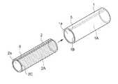
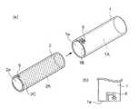
図1は、本発明の一実施形態に係る表面コアと芯コアの構成を示した全体図、図2は表面コアの内側に芯コアを挿入した状態におけるコアを示し、(a)はコアの全体図、(b)はコアの径方向の断面図である。 FIG. 1 is an overall view showing the configuration of a surface core and a core according to an embodiment of the present invention. FIG. 2 shows the core in a state where the core is inserted inside the surface core. (B) is a radial cross-sectional view of the core.
図1及び図2に示されるように、本実施形態に係るコア10は、円筒状の表面コア1と円筒状の芯コア2を有する。表面コア1の内部は円筒状の空洞1Aであって、その空洞1Aの両端は円形状の開口1aとなっている。表面コア1の表面には、長尺状のフィルムが巻き取られるため、接したフィルムに傷や痕を付けないように表面が滑らか(凹凸のない面一状)であることが好ましい。また、表面コア1の材料は特に限定されないが、巻き始め時の段差によるフィルム痕を軽減させる場合には、上述したように発泡PE(ポリエチレン)やゴム、紙、PE、PVC、ポリ乳酸、熱可塑性樹脂、熱硬化性樹脂、テフロン(登録商標)、カーボン(グラファイト)等の低硬度の材料を単独又は複合化して使用することが好ましく、特に、芯コア2よりも硬度が低い材料を用いることが好ましい。表面コア1の円筒の長さや厚みは特に限定されることはなく、巻き付けるフィルムの特性(長尺、幅、厚み、総重量等)や保管、輸送条件等に応じて、適宜選択することができる。 As shown in FIGS. 1 and 2, a
芯コア2は、外径が表面コア1の内径と略同一の円筒状であって、内部に円筒状の空洞2Aを有し、その空洞2Aの両端は円形状の開口2aとなっている。ここで表面コアの内径と芯コアの外径が略同一(略等しい)とは、芯コアを方面コアに軸方向に挿脱することができ、挿入時に両者が隙間なく密着できることを意味する。 The
芯コア2の材料は特に限定されず、紙、PVC、ABS、PS、フェノール含浸紙、FRP、PE、ポリ乳酸、熱可塑性樹脂、熱硬化性樹脂、テフロン(登録商標)、カーボン(グラファイト)、セラミックス、アルミや鉄等金属材料等、用途に応じて、様々な材料を単独又は複合化して用いることができる。芯コア2の円筒の長さは、表面コア1と略同じであるが、表面コア1の円筒の長さ以上にしても良い。芯コア2の円筒の長さが表面コア1の円筒の長さ以上になることで表面コアの着脱作業が容易となり、巻取り時や保管輸送時にフィルムの両端を保護することができる。また、芯コア2の内径や厚みは特に限定されないが、芯コア2の内部空洞2Aにはフィルム巻装装置の回転軸が挿入されるため、使用する装置に合わせて設計すれば良い。さらに、表面コア1は、芯コア2に対して着脱可能となっていれば良く、軸方向に分離したものであっても良い。例えば、芯コア2に対して、その両サイドが所定の長さ(例えば、150mm程度)分だけ引き抜いて着脱できるような構造であっても良い。 The material of the
図2(b)に示すように、図2(a)のコア10の径方向の断面において、表面コア1の内径と芯コア2の外径は略一致するように形成されており、前記芯コア2を前記表面コア1の内側に、図1の矢印のように軸方向に挿入すると、図2(a)のように重ね合せることができコア10となる。 As shown in FIG. 2B, in the radial cross section of the
コア10の使用回数が増大し、表面コア1の表面が傷付いたり、変形したりした場合には容易に交換することができる。交換時には、表面コア1から芯コア2を軸方向に引抜き、新しい表面コア1を芯コア2に挿入して重ね合せることによって交換する。従来技術のように、表面コアの剥離作業が生じないため、時間とコストを要しない。また、表面コア1の剥離作業がないことから、芯コア2の表面に、表面コア1の一部や接着剤等が残存したり、芯コア2の表面の一部が剥がれてしまったりことはないため、芯コア2の再利用性を向上することができる。 If the number of uses of the
また、表面コア1と芯コア2は別々に製造され、これらを後工程で着脱可能に重ね合せるため、各材料の組合せは、用途に応じて柔軟に選択できる。 In addition, since the
上記したように、表面コア1には、芯コア2に比べて低硬度の材料が用いられることが好ましく、その場合、表面コア1と芯コア2を重ね合せたコア10に対してフィルムの巻き取りが進むと、柔らかい表面コア1が巻き締められることによって、表面コア1は芯コア2に固定されるようになる。しかしながら、巻き始めにおいても表面コア1と芯コア2が一体的に回転するようにしたい場合や、継続的に強固な固定を保持したい場合等には、固定手段を設けることが好ましい。このような固定方法には、重ね合せた芯コアと表面コアをテープやラバー等の滑り止め材、疑似接着剤等で固定したり、芯コアと表面コアの隙間をエアー緩衝剤で埋めたり、重ね合せた芯コアと表面コアを両端部から締め付けて固定したりする方法が考えられるが、表面コア1と芯コア2に規制部を設けて固定するようにすると、コア10以外に別途固定用部材を用意する必要がないため、効率的で便利である。 As described above, it is preferable that a material having a lower hardness than the
次に図3を参照して、表面コア1と芯コア2を固定するための規制部について説明する。表面コア1の内面1Bには軸方向に延在する凸部5が形成されており、芯コア2の外面2Cには軸方向に延在する凹部6が形成されている。芯コア2を表面コア1の開口1aから挿入する際、この凸部5と凹部6の周方向の位置が一致するように差し込むと、凸部5が凹部6に係合した状態で表面コア1と芯コア2が重ね合わされる。この凸部5と凹部6の係合によって、表面コア1と芯コア2は周方向の回転が規制された状態で固定されるため、フィルムを巻取る際に、表面コア1と芯コア2が変位することなく一体的に回転可能となり、摩耗を防止することができる。 Next, with reference to FIG. 3, a regulating portion for fixing the
なお、表面コア1の内面1Bに形成される規制部が凹部で、芯コア2の外面2Cに形成される規制部が凸部であっても良く、また係合形状は凸凹に限定されず、表面コア1と芯コア2の周方向の回転を規制できる規制部が設けられており、規制部によって表面コア1と芯コア2を固定できる形態であれば良い。 The restricting portion formed on the
図4(a)(b)は、表面コア1と芯コア2の周方向の回転を規制できる規制部の別の実施形態を示す。(a)は表面コア1と芯コア2の構成を示す全体図、(b)は表面コア1の開口1a付近を上面から見た平面図である。図4(a)に示すように表面コア1の開口1a付近には、周方向と軸方向の経路が組み合わされたクランク状の溝8が形成されており、芯コア2の開口2a付近の外面2Cには突起9が形成されている。芯コア2を表面コア1の開口1aから挿入する際、この溝8と突起9の周方向の位置が一致するように差し込む。この際、図4(b)に矢印で示されるように、突起9は開口1aと繋がる溝8に沿って軸方向に進行する。次に芯コア2を時計回りに回転させると、突起9は周方向の溝8に沿って移動し、その後芯コア2を軸方向に若干引抜くと、突起9は軸方向の溝8に沿って移動し、最後に芯コアを周方向のいずれかに回転させると、突起9は溝8の終点に留まるようになる。溝8の終点においては、溝9の周方向の回転が規制されると共に、軸方向の移動も規制された状態となる。 FIGS. 4A and 4B show another embodiment of the restricting portion that can restrict the circumferential rotation of the
このようにして突起9とクランク状の溝8によって、表面コア1と芯コア2は周方向の回転が規制された状態で固定されるため、フィルムを巻取る際に、表面コア1と芯コア2が変位することなく一体的に回転可能となる。また、本実施形態においては表面コア1と芯コア2は軸方向の移動も規制された状態で固定されるため、表面コア1と芯コア2が軸方向にずれることも防止できる。回転時に表面コア1と芯コア2が軸方向にずれると、巻取ったフィルムの軸方向の両端の位置が回転と共にずれてしまう恐れがあるため、軸方向の規制も講じることによってこのような問題を防ぐことができる。 In this way, the
以上、本発明の実施形態について説明してきたが、本発明は、上記した実施形態に限定されず、その要旨を逸脱しない範囲で種々変形して実施できる。例えば、コア10は、表面コア1と芯コア2はそれぞれが複数層構造を有していても良く、用途に応じて任意に設計できる。また、表面コアと芯コアについては、用途に応じて様々な材料を組み合わせすることができる。また、規制部の形態も周方向の回転を規制できるものであれば良く、例えば、芯コアの外面と表面コアの内面の一部がネジ嵌合するような構造であったり、芯コアの外面と表面コアの内面に傾斜を形成して周方向の回転を規制したり、表面コアの一部に形成した穴に芯コアとネジ固定したりする形態であっても良い。或いは、スリーブロールのようにサイドから締め付け固定するもの、緩まないナット構造等であっても良い。 Although the embodiments of the present invention have been described above, the present invention is not limited to the above-described embodiments, and can be variously modified and implemented without departing from the gist thereof. For example, in the
1 表面コア
1A 表面コアの内部空洞
1a 表面コアの開口
1B 表面コアの内面
2 芯コア
2A 芯コアの内部空洞
2a 芯コアの開口
2C 芯コアの外面
5 凸部(規制部)
6 凹部(規制部)
8 溝(規制部)
9 突起(規制部)
10 コア
6 recess (regulator)
8 groove (regulator)
9 Projection (Regulator)
10 core
Claims (3)
Translated fromJapanese外径が表面コアの内径と略同一であって、表面コアの内側に挿入されて隙間なく密着する円筒状の芯コアとを有し、
前記円筒状に形成された表面コアは、前記芯コアに比べて低硬度材料で形成されており、前記円筒状に形成された芯コアに対して軸方向に着脱して交換可能であり、
前記表面コア及び芯コアには、表面コアを芯コアに対して固定する際、周方向の回転を規制する規制部が設けられており、
前記規制部は、前記表面コアの内面及び前記芯コアの外面に形成され、軸方向の全長に亘って延在し、芯コアに対して表面コアを軸方向に対して挿脱可能にする凹凸部であることを特徴とするコア。A surface core thatis formed into a cylindrical, smooth surface without irregularities, and a long film is wound up ,
The outer diameter is substantially the same as the inner diameter of the surface core, andhas a cylindrical core core that is inserted inside the surface core andclosely adheres without gaps ,
Surface coreformed in thecylindricalshape, theare formed of a low-hardness material than the centercore,Ri replaceable der to removable axiallyrelative to the center core formed in the cylindricalshape,
The surface core and the core core, when fixing the surface core to the core core, provided with a regulating portion that regulates the rotation in the circumferential direction,
The regulating portion is formed on the inner surface of the surface core and the outer surface of the core core, extends over the entire length in the axial direction, and allows the surface core to be inserted into and removed from the core core in the axial direction. A core characterized bybeing a part .
外径が表面コアの内径と略同一であって、表面コアの内側に挿入されて隙間なく密着する円筒状の芯コアとを有し、
前記円筒状に形成された表面コアは、前記芯コアに比べて低硬度材料で形成されており、前記円筒状に形成された芯コアに対して軸方向に着脱して交換可能であり、
前記表面コア及び芯コアには、表面コアを芯コアに対して固定する際、周方向の回転を規制する規制部が設けられており、
前記規制部は、前記表面コアの開口付近及び前記芯コアの開口付近に形成されるクランク状の溝と、クランク状の溝に差し込まれる突起であり、芯コアに対して表面コアを挿入して両者が密着した際、軸方向の移動も規制することを特徴とするコア。A surface core thatis formed into a cylindrical, smooth surface without irregularities, and a long film is wound up ,
The outer diameter is substantially the same as the inner diameter of the surface core, andhas a cylindrical core core that is inserted inside the surface core andclosely adheres without gaps ,
Surface coreformed in thecylindricalshape, theare formed of a low-hardness material than the centercore,Ri replaceable der to removable axiallyrelative to the center core formed in the cylindricalshape,
The surface core and the core core, when fixing the surface core to the core core, provided with a regulating portion that regulates the rotation in the circumferential direction,
The regulating portion is a crank-shaped groove formed near the opening of the surface core and near the opening of the core core, and a projection inserted into the crank-shaped groove. A core characterized in that when both are in close contact, axial movement is also restricted.
Priority Applications (1)
| Application Number | Priority Date | Filing Date | Title |
|---|---|---|---|
| JP2016075554AJP6624733B2 (en) | 2016-04-05 | 2016-04-05 | Core for winding film |
Applications Claiming Priority (1)
| Application Number | Priority Date | Filing Date | Title |
|---|---|---|---|
| JP2016075554AJP6624733B2 (en) | 2016-04-05 | 2016-04-05 | Core for winding film |
Publications (2)
| Publication Number | Publication Date |
|---|---|
| JP2017186120A JP2017186120A (en) | 2017-10-12 |
| JP6624733B2true JP6624733B2 (en) | 2019-12-25 |
Family
ID=60043806
Family Applications (1)
| Application Number | Title | Priority Date | Filing Date |
|---|---|---|---|
| JP2016075554AActiveJP6624733B2 (en) | 2016-04-05 | 2016-04-05 | Core for winding film |
Country Status (1)
| Country | Link |
|---|---|
| JP (1) | JP6624733B2 (en) |
Families Citing this family (1)
| Publication number | Priority date | Publication date | Assignee | Title |
|---|---|---|---|---|
| KR102155952B1 (en)* | 2019-01-21 | 2020-09-14 | 장한얼 | Method for film roll transport and cutting and Film roll core protection devices used therefor |
Family Cites Families (7)
| Publication number | Priority date | Publication date | Assignee | Title |
|---|---|---|---|---|
| JPS48102323U (en)* | 1972-03-07 | 1973-12-01 | ||
| JPH058284Y2 (en)* | 1987-04-01 | 1993-03-02 | ||
| US5236141A (en)* | 1992-03-25 | 1993-08-17 | Kewin Daniel D | Tubular core assemblies for rolls of paper or other sheet material |
| JPH06254938A (en)* | 1993-03-02 | 1994-09-13 | Tenryu Ind Co Ltd | Take-up core and manufacture thereof |
| JP3415773B2 (en)* | 1998-06-09 | 2003-06-09 | 株式会社角田ブラシ製作所 | Rotary polishing roll |
| CA2886879A1 (en)* | 2012-10-04 | 2014-04-10 | 3M Innovative Properties Company | Looped pile film roll core |
| CN205772486U (en)* | 2016-06-11 | 2016-12-07 | 苏州兆管鑫塑料科技有限公司 | Rolling machine and rolling machine core pipe |
- 2016
- 2016-04-05JPJP2016075554Apatent/JP6624733B2/enactiveActive
Also Published As
| Publication number | Publication date |
|---|---|
| JP2017186120A (en) | 2017-10-12 |
Similar Documents
| Publication | Publication Date | Title |
|---|---|---|
| US9683698B2 (en) | High pressure tank | |
| US9908656B2 (en) | Capped wrap dispenser | |
| JP2016223569A (en) | Tank manufacturing method | |
| JP6624733B2 (en) | Core for winding film | |
| US11591180B2 (en) | Wrap dispenser | |
| US20090054219A1 (en) | Spool assembly | |
| JPH09100068A (en) | Core of web | |
| US20150165703A1 (en) | Tank and method of manufacturing the same | |
| US20170036215A1 (en) | Guide Roller Of A Pair Of Feed Rollers Of A Granulating Device | |
| JP5274082B2 (en) | Fiber reinforced resin core | |
| JP6170921B2 (en) | Film roll core, film roll and film roll manufacturing method | |
| JP2002119180A (en) | Fishing rod | |
| WO2006082374A1 (en) | Web-winding core | |
| JP2015161805A5 (en) | ||
| US20090232587A1 (en) | Handgrip mounting method | |
| JP7044003B2 (en) | High pressure tank | |
| JP7022408B2 (en) | Shape holder for solder wire coil | |
| JPH09123555A (en) | Bobbin and cassette for transfer film | |
| JP5303926B2 (en) | Paper-wrapping method and paper-wrapped product on a columnar body | |
| JP2008127191A (en) | Winding core for winding sheet material | |
| JP2008184315A (en) | Ribbon branch | |
| JP2006231758A (en) | Mounting method of printing form plate to sleeve | |
| JP5033260B1 (en) | Label roll body | |
| JP2011236041A (en) | Cylindrical element for winding soft sheet | |
| JP2004174929A (en) | Cylindrical member and its manufacturing method |
Legal Events
| Date | Code | Title | Description |
|---|---|---|---|
| A621 | Written request for application examination | Free format text:JAPANESE INTERMEDIATE CODE: A621 Effective date:20181010 | |
| A977 | Report on retrieval | Free format text:JAPANESE INTERMEDIATE CODE: A971007 Effective date:20190718 | |
| A131 | Notification of reasons for refusal | Free format text:JAPANESE INTERMEDIATE CODE: A131 Effective date:20190808 | |
| A521 | Request for written amendment filed | Free format text:JAPANESE INTERMEDIATE CODE: A523 Effective date:20190920 | |
| TRDD | Decision of grant or rejection written | ||
| A01 | Written decision to grant a patent or to grant a registration (utility model) | Free format text:JAPANESE INTERMEDIATE CODE: A01 Effective date:20191121 | |
| A61 | First payment of annual fees (during grant procedure) | Free format text:JAPANESE INTERMEDIATE CODE: A61 Effective date:20191125 | |
| R150 | Certificate of patent or registration of utility model | Ref document number:6624733 Country of ref document:JP Free format text:JAPANESE INTERMEDIATE CODE: R150 | |
| R250 | Receipt of annual fees | Free format text:JAPANESE INTERMEDIATE CODE: R250 | |
| R250 | Receipt of annual fees | Free format text:JAPANESE INTERMEDIATE CODE: R250 | |
| R250 | Receipt of annual fees | Free format text:JAPANESE INTERMEDIATE CODE: R250 |