JP6622437B2 - Handheld vaporizer - Google Patents
Handheld vaporizerDownload PDFInfo
- Publication number
- JP6622437B2 JP6622437B2JP2019121123AJP2019121123AJP6622437B2JP 6622437 B2JP6622437 B2JP 6622437B2JP 2019121123 AJP2019121123 AJP 2019121123AJP 2019121123 AJP2019121123 AJP 2019121123AJP 6622437 B2JP6622437 B2JP 6622437B2
- Authority
- JP
- Japan
- Prior art keywords
- opening
- cavity
- valve
- flow
- conductive textile
- Prior art date
- Legal status (The legal status is an assumption and is not a legal conclusion. Google has not performed a legal analysis and makes no representation as to the accuracy of the status listed.)
- Active
Links
- 239000006200vaporizerSubstances0.000titleclaimsdescription27
- 238000010438heat treatmentMethods0.000claimsdescription64
- 239000007788liquidSubstances0.000claimsdescription38
- 239000004753textileSubstances0.000claimsdescription26
- 230000008016vaporizationEffects0.000claimsdescription13
- 238000009834vaporizationMethods0.000claimsdescription12
- 239000004744fabricSubstances0.000claimsdescription11
- 239000000463materialSubstances0.000claimsdescription8
- 238000000034methodMethods0.000claimsdescription8
- 229920000642polymerPolymers0.000claimsdescription8
- 230000008859changeEffects0.000claimsdescription7
- 229910052751metalInorganic materials0.000claimsdescription5
- 239000002184metalSubstances0.000claimsdescription5
- 239000011248coating agentSubstances0.000claimsdescription4
- 238000000576coating methodMethods0.000claimsdescription4
- 238000002156mixingMethods0.000claimsdescription4
- 229910001220stainless steelInorganic materials0.000claimsdescription3
- 229910052782aluminiumInorganic materials0.000claimsdescription2
- XAGFODPZIPBFFR-UHFFFAOYSA-NaluminiumChemical compound[Al]XAGFODPZIPBFFR-UHFFFAOYSA-N0.000claimsdescription2
- 239000002131composite materialSubstances0.000claimsdescription2
- 229920000728polyesterPolymers0.000claimsdescription2
- 150000001875compoundsChemical class0.000claims6
- 239000003570airSubstances0.000description16
- 239000000443aerosolSubstances0.000description14
- 239000011162core materialSubstances0.000description9
- 239000003571electronic cigaretteSubstances0.000description7
- WSFSSNUMVMOOMR-UHFFFAOYSA-NFormaldehydeChemical compoundO=CWSFSSNUMVMOOMR-UHFFFAOYSA-N0.000description6
- SNICXCGAKADSCV-JTQLQIEISA-N(-)-NicotineChemical compoundCN1CCC[C@H]1C1=CC=CN=C1SNICXCGAKADSCV-JTQLQIEISA-N0.000description5
- 230000009471actionEffects0.000description5
- 229960002715nicotineDrugs0.000description5
- SNICXCGAKADSCV-UHFFFAOYSA-NnicotineNatural productsCN1CCCC1C1=CC=CN=C1SNICXCGAKADSCV-UHFFFAOYSA-N0.000description5
- 239000000047productSubstances0.000description5
- DNIAPMSPPWPWGF-UHFFFAOYSA-NPropylene glycolChemical compoundCC(O)CODNIAPMSPPWPWGF-UHFFFAOYSA-N0.000description3
- 230000015572biosynthetic processEffects0.000description3
- 235000019504cigarettesNutrition0.000description3
- 238000001704evaporationMethods0.000description3
- 230000008020evaporationEffects0.000description3
- 238000013021overheatingMethods0.000description3
- PEDCQBHIVMGVHV-UHFFFAOYSA-NGlycerineChemical compoundOCC(O)COPEDCQBHIVMGVHV-UHFFFAOYSA-N0.000description2
- 230000000845anti-microbial effectEffects0.000description2
- 230000007613environmental effectEffects0.000description2
- 210000004072lungAnatomy0.000description2
- 239000003595mistSubstances0.000description2
- 238000012986modificationMethods0.000description2
- 230000004048modificationEffects0.000description2
- 230000003647oxidationEffects0.000description2
- 238000007254oxidation reactionMethods0.000description2
- 239000000126substanceSubstances0.000description2
- WHXSMMKQMYFTQS-UHFFFAOYSA-NLithiumChemical compound[Li]WHXSMMKQMYFTQS-UHFFFAOYSA-N0.000description1
- 238000010521absorption reactionMethods0.000description1
- 230000004913activationEffects0.000description1
- 239000012080ambient airSubstances0.000description1
- 239000004599antimicrobialSubstances0.000description1
- 238000000889atomisationMethods0.000description1
- 230000001580bacterial effectEffects0.000description1
- 239000006227byproductSubstances0.000description1
- 238000006243chemical reactionMethods0.000description1
- 235000019506cigarNutrition0.000description1
- 239000003086colorantSubstances0.000description1
- 238000004891communicationMethods0.000description1
- 230000003247decreasing effectEffects0.000description1
- 230000001627detrimental effectEffects0.000description1
- 239000000428dustSubstances0.000description1
- 238000005516engineering processMethods0.000description1
- 239000012530fluidSubstances0.000description1
- 239000006260foamSubstances0.000description1
- 239000003205fragranceSubstances0.000description1
- 235000011187glycerolNutrition0.000description1
- 230000036541healthEffects0.000description1
- 239000006193liquid solutionSubstances0.000description1
- 229910052744lithiumInorganic materials0.000description1
- 238000007726management methodMethods0.000description1
- WSFSSNUMVMOOMR-NJFSPNSNSA-NmethanoneChemical compoundO=[14CH2]WSFSSNUMVMOOMR-NJFSPNSNSA-N0.000description1
- 239000000203mixtureSubstances0.000description1
- 239000004033plasticSubstances0.000description1
- 229920001296polysiloxanePolymers0.000description1
- 230000008569processEffects0.000description1
- 230000000391smoking effectEffects0.000description1
- 235000013311vegetablesNutrition0.000description1
Images

Classifications
- A—HUMAN NECESSITIES
- A24—TOBACCO; CIGARS; CIGARETTES; SIMULATED SMOKING DEVICES; SMOKERS' REQUISITES
- A24F—SMOKERS' REQUISITES; MATCH BOXES; SIMULATED SMOKING DEVICES
- A24F40/00—Electrically operated smoking devices; Component parts thereof; Manufacture thereof; Maintenance or testing thereof; Charging means specially adapted therefor
- A24F40/50—Control or monitoring
- A24F40/51—Arrangement of sensors
- A—HUMAN NECESSITIES
- A24—TOBACCO; CIGARS; CIGARETTES; SIMULATED SMOKING DEVICES; SMOKERS' REQUISITES
- A24B—MANUFACTURE OR PREPARATION OF TOBACCO FOR SMOKING OR CHEWING; TOBACCO; SNUFF
- A24B15/00—Chemical features or treatment of tobacco; Tobacco substitutes, e.g. in liquid form
- A24B15/10—Chemical features of tobacco products or tobacco substitutes
- A24B15/16—Chemical features of tobacco products or tobacco substitutes of tobacco substitutes
- A24B15/167—Chemical features of tobacco products or tobacco substitutes of tobacco substitutes in liquid or vaporisable form, e.g. liquid compositions for electronic cigarettes
- A—HUMAN NECESSITIES
- A24—TOBACCO; CIGARS; CIGARETTES; SIMULATED SMOKING DEVICES; SMOKERS' REQUISITES
- A24F—SMOKERS' REQUISITES; MATCH BOXES; SIMULATED SMOKING DEVICES
- A24F40/00—Electrically operated smoking devices; Component parts thereof; Manufacture thereof; Maintenance or testing thereof; Charging means specially adapted therefor
- A24F40/10—Devices using liquid inhalable precursors
- A—HUMAN NECESSITIES
- A24—TOBACCO; CIGARS; CIGARETTES; SIMULATED SMOKING DEVICES; SMOKERS' REQUISITES
- A24F—SMOKERS' REQUISITES; MATCH BOXES; SIMULATED SMOKING DEVICES
- A24F40/00—Electrically operated smoking devices; Component parts thereof; Manufacture thereof; Maintenance or testing thereof; Charging means specially adapted therefor
- A24F40/40—Constructional details, e.g. connection of cartridges and battery parts
- A24F40/42—Cartridges or containers for inhalable precursors
- A—HUMAN NECESSITIES
- A24—TOBACCO; CIGARS; CIGARETTES; SIMULATED SMOKING DEVICES; SMOKERS' REQUISITES
- A24F—SMOKERS' REQUISITES; MATCH BOXES; SIMULATED SMOKING DEVICES
- A24F40/00—Electrically operated smoking devices; Component parts thereof; Manufacture thereof; Maintenance or testing thereof; Charging means specially adapted therefor
- A24F40/40—Constructional details, e.g. connection of cartridges and battery parts
- A24F40/46—Shape or structure of electric heating means
- A—HUMAN NECESSITIES
- A24—TOBACCO; CIGARS; CIGARETTES; SIMULATED SMOKING DEVICES; SMOKERS' REQUISITES
- A24F—SMOKERS' REQUISITES; MATCH BOXES; SIMULATED SMOKING DEVICES
- A24F40/00—Electrically operated smoking devices; Component parts thereof; Manufacture thereof; Maintenance or testing thereof; Charging means specially adapted therefor
- A24F40/40—Constructional details, e.g. connection of cartridges and battery parts
- A24F40/48—Fluid transfer means, e.g. pumps
- A24F40/485—Valves; Apertures
- A—HUMAN NECESSITIES
- A24—TOBACCO; CIGARS; CIGARETTES; SIMULATED SMOKING DEVICES; SMOKERS' REQUISITES
- A24F—SMOKERS' REQUISITES; MATCH BOXES; SIMULATED SMOKING DEVICES
- A24F40/00—Electrically operated smoking devices; Component parts thereof; Manufacture thereof; Maintenance or testing thereof; Charging means specially adapted therefor
- A24F40/50—Control or monitoring
- A24F40/57—Temperature control
- A—HUMAN NECESSITIES
- A61—MEDICAL OR VETERINARY SCIENCE; HYGIENE
- A61M—DEVICES FOR INTRODUCING MEDIA INTO, OR ONTO, THE BODY; DEVICES FOR TRANSDUCING BODY MEDIA OR FOR TAKING MEDIA FROM THE BODY; DEVICES FOR PRODUCING OR ENDING SLEEP OR STUPOR
- A61M11/00—Sprayers or atomisers specially adapted for therapeutic purposes
- A61M11/04—Sprayers or atomisers specially adapted for therapeutic purposes operated by the vapour pressure of the liquid to be sprayed or atomised
- A61M11/041—Sprayers or atomisers specially adapted for therapeutic purposes operated by the vapour pressure of the liquid to be sprayed or atomised using heaters
- A61M11/042—Sprayers or atomisers specially adapted for therapeutic purposes operated by the vapour pressure of the liquid to be sprayed or atomised using heaters electrical
- A61M11/044—Sprayers or atomisers specially adapted for therapeutic purposes operated by the vapour pressure of the liquid to be sprayed or atomised using heaters electrical with electrodes immersed in the liquid
- A—HUMAN NECESSITIES
- A61—MEDICAL OR VETERINARY SCIENCE; HYGIENE
- A61M—DEVICES FOR INTRODUCING MEDIA INTO, OR ONTO, THE BODY; DEVICES FOR TRANSDUCING BODY MEDIA OR FOR TAKING MEDIA FROM THE BODY; DEVICES FOR PRODUCING OR ENDING SLEEP OR STUPOR
- A61M15/00—Inhalators
- A61M15/06—Inhaling appliances shaped like cigars, cigarettes or pipes
- F—MECHANICAL ENGINEERING; LIGHTING; HEATING; WEAPONS; BLASTING
- F22—STEAM GENERATION
- F22B—METHODS OF STEAM GENERATION; STEAM BOILERS
- F22B1/00—Methods of steam generation characterised by form of heating method
- F22B1/28—Methods of steam generation characterised by form of heating method in boilers heated electrically
- F22B1/284—Methods of steam generation characterised by form of heating method in boilers heated electrically with water in reservoirs
- H—ELECTRICITY
- H05—ELECTRIC TECHNIQUES NOT OTHERWISE PROVIDED FOR
- H05B—ELECTRIC HEATING; ELECTRIC LIGHT SOURCES NOT OTHERWISE PROVIDED FOR; CIRCUIT ARRANGEMENTS FOR ELECTRIC LIGHT SOURCES, IN GENERAL
- H05B1/00—Details of electric heating devices
- H05B1/02—Automatic switching arrangements specially adapted to apparatus ; Control of heating devices
- H05B1/0227—Applications
- H05B1/0297—Heating of fluids for non specified applications
- H—ELECTRICITY
- H05—ELECTRIC TECHNIQUES NOT OTHERWISE PROVIDED FOR
- H05B—ELECTRIC HEATING; ELECTRIC LIGHT SOURCES NOT OTHERWISE PROVIDED FOR; CIRCUIT ARRANGEMENTS FOR ELECTRIC LIGHT SOURCES, IN GENERAL
- H05B3/00—Ohmic-resistance heating
- H05B3/40—Heating elements having the shape of rods or tubes
- H05B3/42—Heating elements having the shape of rods or tubes non-flexible
- H05B3/46—Heating elements having the shape of rods or tubes non-flexible heating conductor mounted on insulating base
- A—HUMAN NECESSITIES
- A24—TOBACCO; CIGARS; CIGARETTES; SIMULATED SMOKING DEVICES; SMOKERS' REQUISITES
- A24F—SMOKERS' REQUISITES; MATCH BOXES; SIMULATED SMOKING DEVICES
- A24F40/00—Electrically operated smoking devices; Component parts thereof; Manufacture thereof; Maintenance or testing thereof; Charging means specially adapted therefor
- A24F40/60—Devices with integrated user interfaces
- A—HUMAN NECESSITIES
- A61—MEDICAL OR VETERINARY SCIENCE; HYGIENE
- A61M—DEVICES FOR INTRODUCING MEDIA INTO, OR ONTO, THE BODY; DEVICES FOR TRANSDUCING BODY MEDIA OR FOR TAKING MEDIA FROM THE BODY; DEVICES FOR PRODUCING OR ENDING SLEEP OR STUPOR
- A61M16/00—Devices for influencing the respiratory system of patients by gas treatment, e.g. ventilators; Tracheal tubes
- A61M16/0003—Accessories therefor, e.g. sensors, vibrators, negative pressure
- A61M2016/0015—Accessories therefor, e.g. sensors, vibrators, negative pressure inhalation detectors
- A61M2016/0018—Accessories therefor, e.g. sensors, vibrators, negative pressure inhalation detectors electrical
- A61M2016/0024—Accessories therefor, e.g. sensors, vibrators, negative pressure inhalation detectors electrical with an on-off output signal, e.g. from a switch
- A—HUMAN NECESSITIES
- A61—MEDICAL OR VETERINARY SCIENCE; HYGIENE
- A61M—DEVICES FOR INTRODUCING MEDIA INTO, OR ONTO, THE BODY; DEVICES FOR TRANSDUCING BODY MEDIA OR FOR TAKING MEDIA FROM THE BODY; DEVICES FOR PRODUCING OR ENDING SLEEP OR STUPOR
- A61M16/00—Devices for influencing the respiratory system of patients by gas treatment, e.g. ventilators; Tracheal tubes
- A61M16/0003—Accessories therefor, e.g. sensors, vibrators, negative pressure
- A61M2016/0027—Accessories therefor, e.g. sensors, vibrators, negative pressure pressure meter
- A—HUMAN NECESSITIES
- A61—MEDICAL OR VETERINARY SCIENCE; HYGIENE
- A61M—DEVICES FOR INTRODUCING MEDIA INTO, OR ONTO, THE BODY; DEVICES FOR TRANSDUCING BODY MEDIA OR FOR TAKING MEDIA FROM THE BODY; DEVICES FOR PRODUCING OR ENDING SLEEP OR STUPOR
- A61M2205/00—General characteristics of the apparatus
- A61M2205/13—General characteristics of the apparatus with means for the detection of operative contact with patient, e.g. lip sensor
- A—HUMAN NECESSITIES
- A61—MEDICAL OR VETERINARY SCIENCE; HYGIENE
- A61M—DEVICES FOR INTRODUCING MEDIA INTO, OR ONTO, THE BODY; DEVICES FOR TRANSDUCING BODY MEDIA OR FOR TAKING MEDIA FROM THE BODY; DEVICES FOR PRODUCING OR ENDING SLEEP OR STUPOR
- A61M2205/00—General characteristics of the apparatus
- A61M2205/36—General characteristics of the apparatus related to heating or cooling
- A61M2205/3653—General characteristics of the apparatus related to heating or cooling by Joule effect, i.e. electric resistance
- A—HUMAN NECESSITIES
- A61—MEDICAL OR VETERINARY SCIENCE; HYGIENE
- A61M—DEVICES FOR INTRODUCING MEDIA INTO, OR ONTO, THE BODY; DEVICES FOR TRANSDUCING BODY MEDIA OR FOR TAKING MEDIA FROM THE BODY; DEVICES FOR PRODUCING OR ENDING SLEEP OR STUPOR
- A61M2205/00—General characteristics of the apparatus
- A61M2205/50—General characteristics of the apparatus with microprocessors or computers
- A—HUMAN NECESSITIES
- A61—MEDICAL OR VETERINARY SCIENCE; HYGIENE
- A61M—DEVICES FOR INTRODUCING MEDIA INTO, OR ONTO, THE BODY; DEVICES FOR TRANSDUCING BODY MEDIA OR FOR TAKING MEDIA FROM THE BODY; DEVICES FOR PRODUCING OR ENDING SLEEP OR STUPOR
- A61M2205/00—General characteristics of the apparatus
- A61M2205/58—Means for facilitating use, e.g. by people with impaired vision
- A61M2205/583—Means for facilitating use, e.g. by people with impaired vision by visual feedback
- A61M2205/584—Means for facilitating use, e.g. by people with impaired vision by visual feedback having a color code
- A—HUMAN NECESSITIES
- A61—MEDICAL OR VETERINARY SCIENCE; HYGIENE
- A61M—DEVICES FOR INTRODUCING MEDIA INTO, OR ONTO, THE BODY; DEVICES FOR TRANSDUCING BODY MEDIA OR FOR TAKING MEDIA FROM THE BODY; DEVICES FOR PRODUCING OR ENDING SLEEP OR STUPOR
- A61M2205/00—General characteristics of the apparatus
- A61M2205/82—Internal energy supply devices
- A61M2205/8206—Internal energy supply devices battery-operated
Landscapes
- Health & Medical Sciences (AREA)
- Engineering & Computer Science (AREA)
- Life Sciences & Earth Sciences (AREA)
- Veterinary Medicine (AREA)
- Anesthesiology (AREA)
- Public Health (AREA)
- General Health & Medical Sciences (AREA)
- Animal Behavior & Ethology (AREA)
- Hematology (AREA)
- Heart & Thoracic Surgery (AREA)
- Biomedical Technology (AREA)
- Bioinformatics & Cheminformatics (AREA)
- Pulmonology (AREA)
- Sustainable Development (AREA)
- Sustainable Energy (AREA)
- General Engineering & Computer Science (AREA)
- Mechanical Engineering (AREA)
- Thermal Sciences (AREA)
- Physics & Mathematics (AREA)
- Chemical & Material Sciences (AREA)
- Chemical Kinetics & Catalysis (AREA)
- General Chemical & Material Sciences (AREA)
- Catching Or Destruction (AREA)
- Disinfection, Sterilisation Or Deodorisation Of Air (AREA)
- Containers And Packaging Bodies Having A Special Means To Remove Contents (AREA)
- Electrostatic Spraying Apparatus (AREA)
Description
Translated fromJapanese 関連出願への相互参照
本願は、引用により本明細書に完全に組み込まれる、2014年5月22日に出願された「E−Cigarette」という名称の米国特許仮出願第62/001,972号に基づく優先権を主張するものである。CROSS REFERENCE TO RELATED APPLICATIONS This application is hereby incorporated by reference in US Provisional Application No. 62 / 001,972, entitled “E-Cigarette”, filed May 22, 2014, which is fully incorporated herein by reference. Claims priority based on.
本発明は、手持ち式蒸気化装置であって、改善された加熱要素及び温度制御、改善されたe−リキッドリザーバ、並びに装置を要求時にエアロゾルを送達する準備のできた状態にするべく加熱要素を作動させるための静電容量技術を有する装置に関する。 The present invention is a hand-held vaporizer that provides improved heating element and temperature control, improved e-liquid reservoir, and activation of the heating element to make the apparatus ready to deliver aerosol on demand. It is related with the apparatus which has the electrostatic capacitance technology for making it.
電子たばことしても知られている従来の手持ち式蒸気化装置は、バッテリ、アトマイザ、及びe−リキッドカートリッジを備えるバッテリ駆動のポータブル装置である。手持ち式蒸気化装置は、e−リキッドとして知られているリキッド溶液の蒸発によるエアロゾルを発生させることでニコチンを送達するように設計される。e−リキッドは、普通は、プロピレングリコールと、植物性グリセリンと、ニコチンと、香料との混合物を含有するが、他のものは、ニコチンを含有しない、風味のついた蒸気を放出する。 A conventional handheld vaporizer, also known as an electronic cigarette, is a battery-powered portable device that includes a battery, an atomizer, and an e-liquid cartridge. Handheld vaporizers are designed to deliver nicotine by generating an aerosol by evaporation of a liquid solution known as e-liquid. e-Liquid usually contains a mixture of propylene glycol, vegetable glycerin, nicotine and fragrance, while others release flavored vapors that do not contain nicotine.
従来の手持ち式蒸気化装置は、一般に、吸入のためのニコチンエアロゾルを発生させるのにe−リキッドを蒸気化するアトマイザとして知られている加熱要素を用いる。アトマイザは、e−リキッドの蒸気化を担当する加熱要素と、カートリッジからe−リキッドを吸い上げる芯材からなる。抵抗線の形態の加熱要素は、芯材の周りにコイル状に巻かれ、電源に接続される。e−リキッドは、毛管作用によって芯材に吸収される。装置が作動されるときに、加熱コイルが芯材によって吸収されているe−リキッドを加熱し、蒸気化し、吸入のためのエアロゾルを生み出す。 Conventional hand-held vaporizers generally use a heating element known as an atomizer that vaporizes the e-liquid to generate a nicotine aerosol for inhalation. The atomizer consists of a heating element responsible for e-liquid vaporization and a core that sucks the e-liquid from the cartridge. A heating element in the form of a resistance wire is coiled around a core and connected to a power source. The e-liquid is absorbed into the core material by capillary action. When the device is activated, a heating coil heats and vaporizes the e-liquid that is absorbed by the core, creating an aerosol for inhalation.
いくつかの従来技術の手持ち式蒸気化装置は、電源に接続される単一の構成要素に一体化されたアトマイザ及びカートリッジからなる装置である、カトマイザを用いる。従来技術のアトマイザ又はカトマイザの加熱要素は、加熱及び蒸気化の過程を正確に制御しない。芯材の周りの加熱ワイヤの巻きつけの品質及び一貫性の顕著なばらつき、ワイヤの電気抵抗の差異、並びに芯材の効率及び吸収特性の差異が、アトマイザによって発生するエアロゾルの量又は体積及びエアロゾルの知覚される品質に大いに影響する。温度制御の欠如は、結果的に加熱要素の不均一な加熱及び過熱をもたらす場合があり、これは次に、蒸気中に危険な化学物質を生成する場合がある。例えば、e−リキッドの過熱は、結果的にホルムアルデヒドを生成する場合があり、その吸入はユーザの健康に有害である。 Some prior art handheld vaporizers use a atomizer, which is an apparatus consisting of an atomizer and a cartridge integrated into a single component that is connected to a power source. The heating elements of prior art atomizers or cartomizers do not accurately control the heating and vaporization process. Significant variations in the quality and consistency of the wrapping of the heating wire around the core material, differences in the electrical resistance of the wire, and differences in the efficiency and absorption characteristics of the core material are the amount or volume of aerosol generated by the atomizer and the aerosol Greatly affects the perceived quality of. The lack of temperature control can result in uneven heating and overheating of the heating element, which in turn can produce dangerous chemicals in the steam. For example, e-liquid overheating can result in the formation of formaldehyde, which inhalation is detrimental to the user's health.
従来技術の手持ち式蒸気化装置では、ユーザが、e−リキッドを蒸気化するために装置の加熱要素を作動させるべく装置を通じて空気を吸入する必要があった。従来技術の装置が十分な蒸気を発生するようになるまでにユーザは装置を数回ふかすことになり、結果としてユーザにとって非能率的で不便な場合がある。 Prior art handheld vaporizers required the user to inhale air through the device to activate the heating element of the device to vaporize the e-liquid. The user will have to shake the device several times before the prior art device generates enough steam, which may be inefficient and inconvenient for the user.
本発明は、導電性テキスタイル加熱要素と、弾性的に変形可能な材料で作製されるe−リキッドリザーバと、ユーザが装置を通じて最初の吸入を行うのを待たずに装置上のユーザのタッチを感知すると加熱要素を作動させることによって装置を要求時にエアロゾルを送達する準備のできた状態にするための自動オン特徴を含む改善された温度・加熱制御システムとを組み込んでいる新規な手持ち式蒸気化装置を提供することによって従来技術の欠点を克服することに向けられる。本発明に係る導電性テキスタイル加熱要素は、従来技術の芯材及びコイルの霧化システムを代替し、毛管作用によってe−リキッドを吸い上げ、従来の芯材システムよりもe−リキッドのより均一な直接加熱を可能にする。 The present invention senses a user's touch on the device without waiting for the user to make the first inhalation through the device, an electrically conductive textile heating element, an e-liquid reservoir made of an elastically deformable material A new hand-held vaporizer that incorporates an improved temperature and heating control system that includes an auto-on feature to activate the heating element to make the device ready for aerosol delivery on demand. The provision is directed to overcoming the disadvantages of the prior art. The conductive textile heating element according to the present invention replaces the prior art core and coil atomization system, sucks the e-liquid by capillary action, and makes the e-liquid more uniform direct than the conventional core system. Allow heating.
本発明の一実施形態に係る手持ち式蒸気化装置をここで図1〜図3を参照して説明する。 A handheld vaporizer according to an embodiment of the present invention will now be described with reference to FIGS.
図1は、長手方向軸を有し、かつ、第1の長手方向の第1の長手方向端及び反対に配置される第2の長手方向の第2の長手方向端を備える、手持ち式蒸気化装置10を例示する。手持ち式蒸気化装置10は、マウスピース200及びメインボディ100を備える。メインボディ100は内部キャビティ110を画定する。加熱要素240、リザーバ250、制御回路270及び電源290を備える電源ユニット260、並びに電源接続要素280がキャビティ110内に順次に設けられる。 FIG. 1 shows a handheld vaporization having a longitudinal axis and comprising a first longitudinal end of a first longitudinal direction and a second longitudinal end of a second longitudinal direction arranged oppositely The
ユーザの唇の間に保持されるように適合され、第1の端200a及び第2の端200bを有するマウスピース200が、ボディ100の第1の長手方向端に接続される。好ましい実施形態では、マウスピース200は、普通のたばこのフィルタの感触を模擬するために、環状に形状設定され、例えば、金属又はプラスチックなどの硬質材料の内側シェルと、例えば、発泡体、シリコーン、又はゴムなどの柔軟な軟質材料の外側シェルを備える。マウスピース200はまた、細菌増殖を抑制するために抗菌剤コーティングを含んでもよい。例えば、Microban(http://www.microban.com/)又は別の同等の供給業者などの市販の抗菌製品が当該技術分野では公知の方法に従って用いられてもよい。 A
ユーザがマウスピース200に呼吸の吸息をするときにエアロゾルが装置10の外に吸い出されてユーザの肺に入ることを可能にするためにマウスピース200の端200aに開口部210が設けられる。好ましい実施形態では、開口部210は、直径1mm〜1.5cmの概して円形の断面を有する。他の実施形態では、開口部210は、四角形、三角形、又は任意の他の幾何学的断面形状を有してもよい。 An
ユーザが吸入するときにエアロゾルがマウスピース200に入ることを可能にするためにマウスピース200の反対端200bに開口部230が設けられる。好ましい実施形態では、開口部230は、直径1mm〜1.5cmの概して円形の断面を有する。他の実施形態では、開口部230は、四角形、三角形、又は任意の他の幾何学的断面形状を有してもよい。 An
好ましくは、開口部230を開閉するために空気入口逆止め弁220が設けられる。空気入口逆止め弁220は、例えば、Smart Products,Inc.(http://www.smartproducts.com/check_valves_series_100_cartridge.php)又は別の同等の供給業者からの市販の製品であってもよい。好ましい実施形態では、Series 100 Cartridge Check Valve(http://www.smartproducts.com/check_valves_series_100_cartridge.phpで見られる)が用いられてもよい。 Preferably, an air
逆止め弁220は、e−リキッドの蒸発及び酸化を防ぐため、及びe−リキッドの鮮度を維持するために、装置10が使用中ではないときに環境空気が開口部210及び230を通ってボディ100の内部に入るのを防ぐ。加えて、弁220は、ユーザのポケット、バッグ、財布などの中で運ばれるときにe−リキッドが装置の外に漏れるのを防ぎ、塵埃が装置の中に入らないようにする。 The
電源接続要素280は、ボディ100の第2の反対の長手方向端内に配置される。好ましい実施形態では、電源接続要素280は、ユーザが特に電子たばこ用に作製されたアダプタ又は充電器なしに装置10を充電するのにユニバーサルチャージャを使用できるようにするために、外部電源と差し込み式に接続するためのユニバーサルシリアルバス(USB)インターフェースを備える。他の実施形態では、電源接続要素280は、ミニUSBインターフェース、マイクロUSBインターフェース、又は当該技術分野では公知の任意の他の適切な通信バスを備えてもよい。 The
キャビティ110は、電源接続要素280に電気的に結合される電源要素260を含む。電源要素260は、マイクロプロセッサ制御回路270及び電源290を備える。本発明の一実施形態によれば、電源は、リチウムポリマーバッテリであってもよい。
キャビティ110は、詰め替え可能であっても又は使い捨てであってもよいe−リキッドリザーバ250を含む。リザーバ250は、当該技術分野では公知のポリマー又は金属/ポリマー複合材などの弾性的に変形可能な材料で作製されてもよい。本発明の一実施形態によれば、リザーバ250は、アルミニウムプリントされた外面を有するポリエステルで作製されてもよく、少なくとも5mlの体積であってもよい。この材料は、不活性であり、外部環境因子がリザーバの内容物のリキッドと相互作用しないようにする。弾性的に変形可能なリザーバは、ユーザが異なるタイプのe−リキッドを装置に挿入することを可能にし、かつ、e−リキッドが装置によって使い果たされることも可能にし、これはリザーバ内に残っている流体の一部が芯材に届かず使用できない剛性のリザーバを有する従来技術の装置を上回る利点を提供する。
キャビティ110は、リザーバ250に流体的に結合され、電源要素260に電気的に結合される、加熱要素240をさらに含む。本発明に係る加熱要素240は導電性テキスタイル加熱要素を含む。本発明に係る導電性テキスタイル加熱要素は、メタライズされた又は導電性コーティングを有するファブリック、織られた金属ストランドを組み込んでいるファブリック、又は当該技術分野では公知の任意の他の適切な材料で作製される加熱要素を含む。本発明の一実施形態によれば、超薄型ステンレス鋼ワイヤークロス(http://www.saati.com/bopp−wire.phpで見られる又は別の同様の供給業者からのものが用いられてもよい)が用いられてもよく、スポンジ又は多プライ電子テキスタイルクロスを形成するべく層状にされてもよい。本発明の一実施形態によれば、400スレッド/インチを有する微細メッシュ材料のBoppステンレス鋼ワイヤークロスが、e−リキッドを確実に速く均一に加熱するために用いられてもよい。
e−リキッドは、毛管作用により導電性テキスタイル加熱要素に到達し、導電性テキスタイル加熱要素の加熱作用によって蒸気化される。加熱・温度制御システムと結合される導電性テキスタイル加熱要素を設けることによって、本発明に係る電子たばこは、e−リキッドがホルムアルデヒドなどの望ましくない化学物質に変化することを最小限に抑える又はなくすために最適な蒸気化状態を絶えず一貫して維持することを可能にする。 The e-liquid reaches the conductive textile heating element by capillary action and is vaporized by the heating action of the conductive textile heating element. By providing a conductive textile heating element coupled with a heating and temperature control system, the electronic cigarette according to the present invention minimizes or eliminates the conversion of e-liquid to undesirable chemicals such as formaldehyde. Makes it possible to maintain an optimal vaporization state constantly and consistently.
空気開口部130が、ボディ100の第1の長手方向端とキャビティ110内の加熱要素240の位置に対応するボディ100の外面上の位置との間のボディ100の外面上に配置される。好ましい実施形態では、開口部130は、直径1mm〜1.5cmの概して円形の断面を有する。他の実施形態では、開口部130は、四角形、三角形、又は任意の他の幾何学的断面形状を有してもよい。他の実施形態は、複数の空気開口部130を備えてもよい。装置に入る空気が、導電性テキスタイル加熱要素の周囲領域での空気の混合を可能にするのに十分なだけ高い速度で移動するようにするために、開口部130の総断面積は、開口部230の総断面積よりも小さくすべきである。 An
好ましくは、各開口部130を開閉するために空気入口逆止め弁120が設けられる。空気入口逆止め弁120は、e−リキッドの蒸発及び/又は酸化を防ぐために、電子たばこ10が使用中ではないときに環境空気がキャビティ110に入るのを防ぐ。空気入口逆止め弁120は、例えば、Smart Products,Inc.(http://www.smartproducts.com/check_valves_series_100_cartridge.php)又は別の同等の供給業者からの市販の製品であってもよい。好ましい実施形態では、Series 100 Cartridge Check Valve(http://www.smartproducts.com/check_valves_series_100_cartridge.phpで見られる)が用いられてもよい。別の実施形態では、ボディ100に取り付けられる弾性軟質ポリマーフラップが、空気入口逆止め弁120の代わりに用いられてもよい。空気入口逆止め弁120か又は弾性軟質ポリマーフラップのいずれかを開くのに必要な開口圧力は、ユーザが無理なく吸入できるようにするために最小(例えば、0.5PSI)に減少されるべきである。 Preferably, an air
ユーザは、吸入するときにマウスピース200内に陰圧領域を生み出す。空気入口逆止め弁120か又は弾性軟質ポリマーフラップのいずれかを開くのに必要な開口圧力は、ユーザが無理なく吸入できるようにするために最小(例えば、0.5PSI)に減少されるべきである。ユーザの吸入により、装置のマウスピースに存在する圧力センサスイッチが装置をオンにし、電源要素260から電流を流すことによって加熱要素240を作動させ、これにより、e−リキッドの一部を蒸気化し、エアロゾルミストを発生させる。ユーザの吸入によって生み出された陰圧により弁120及び220が開き、これにより、外部空気が開口部130を通ってキャビティ110に入ることが可能となる。次いで、エアロゾルミストが、外部空気と合流し、マウスピース200を通過し、開口部210を通ってユーザの肺に入る。 The user creates a negative pressure area in the
LED要素140(LEDライト及びLEDドライバを備える)及び光チャネル150が、ボディ100の上方の外面上に配置され、電源要素260に電気的に接続される。本発明の別の実施形態によれば、Texas Instruments,Inc.(http://www.ti.com/lsds/ti/power−management/indicator−rgbw−overview.page)からの又は別の同様の供給業者からの組み込みLEDドライバを有する市販のマイクロプロセッサが用いられてもよい。 An LED element 140 (comprising an LED light and an LED driver) and a
本発明の一実施形態によれば、LED要素140は、光がユーザに見えるようにするために光をボディ100の上面に沿ってチャネル150を介して導く。他の実施形態によれば、LED要素140は、マウスピース200を組み込む、ボディ100の第1の端とは反対のボディ100の第2の長手方向端に組み込まれてもよい。LEDライト140は、ユーザが電子たばこから吸入するときにマイクロプロセッサ制御回路270によって作動されてもよい。LED光の強度は、当該技術分野では公知の方法に従って、マイクロプロセッサ回路によって及びマウスピースに存在する圧力センサによって制御される。圧力センサスイッチが、ユーザの吸入によって生み出される、より高い陰圧を感知すると、マイクロプロセッサ回路270が、より高いデューティサイクルをLED要素140に送ることになる。デューティサイクルは、回路がオンの時間と回路がオフの時間との比である。 According to one embodiment of the present invention, the
LEDライト140及び光チャネル150は、電子たばこ10の使用量、バッテリレベル、又は他の機能パラメータを表すために種々の色の光及び一連の光の点滅を表示してもよい。光の色又は強度は、ユーザが吸入した、従来のたばこに対するニコチンの等価な使用量を示すために、電子たばこ10の使用中に徐々に変化してもよい。例えば、一連の光は、バッテリの満充電量に関して「緑」、約半分の充電量に関して「黄」、及びバッテリが再充電を必要とするときは「赤」であってもよい。装置に残っているe−リキッドの量を示すために同様のカラースキームが使用されてもよい。 The
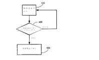
図2は、本発明に係る手持ち式蒸気化装置10の加熱要素240を制御するための「自動オン」システムの動作を例示する。手持ち式蒸気化装置10は、静電容量タッチセンサ要素190を組み込む。静電容量タッチセンサ要素190は、図1に例示されるように装置10のボディ100に組み込まれてもよい。他の実施形態によれば、静電容量タッチセンサ要素190は、装置10のマウスピース200に組み込まれてもよい。 FIG. 2 illustrates the operation of an “automatic on” system for controlling the
図2のステップ400において、マイクロプロセッサ制御回路270のソフトウェア及びハードウェアが、当該技術分野では公知の方法に従って、静電容量センサ190がアクティブであるか又は非アクティブであるかを判定する。ユーザが装置10にタッチしているために静電容量タッチセンサ要素190がアクティブのとき、ステップ420で例示されるように加熱要素240がオンにされ、加熱要素240の蒸気化作用によって蒸気が生み出され、これにより、ユーザが要求時に蒸気を楽しむことが可能となる。ユーザが装置10にタッチしていないために静電容量タッチセンサ要素190が非アクティブのとき、図2のステップ410で例示されるように加熱要素240がオフにされる。 In
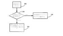
図3は、本発明に係る加熱要素240の加熱デューティサイクルを制御するための加熱・温度制御システムの動作を例示する。図3のステップ300に示すように、ユーザが装置10にタッチしているために静電容量センサ190がアクティブのとき、加熱要素240が作動され、そのデューティサイクルは、e−リキッドをe−リキッドの最適な設定蒸気化温度に加熱するようにマイクロプロセッサ制御回路270によって制御される。これは、ユーザの最初の吸入を待たずにユーザが装置にタッチするときにエアロゾルが生み出されることを可能にする。したがって、エアロゾルは、ユーザがエアロゾルの最初のドーズを生み出すべく装置を1回以上ふかす必要なしにすぐに消費することができ、これにより、本物のたばこ又はシガーの喫煙体験をより近く模擬する。ステップ310で例示されるように、加熱要素は、確実に蒸気を供給し、かつ、e−リキッドの過熱による望ましくない副生成物の生成を防ぐために、最適な設定蒸気化温度を著しく超えたり又はそれよりも下がったりしないように、当該技術分野では公知の方法によってマイクロプロセッサ制御回路270によって制御される。本発明の一実施形態によれば、加熱要素は、ホルムアルデヒドの生成を防ぐために120℃を超えないように制御されるべきである。 FIG. 3 illustrates the operation of the heating and temperature control system for controlling the heating duty cycle of the
図3のステップ320で例示されるように、加熱要素240の温度がe−リキッドの最適な設定蒸気化温度を上回る又は下回る場合、加熱要素240の温度をe−リキッドの最適な設定蒸気化温度に維持するためにマイクロプロセッサ制御回路270によって加熱要素240のデューティサイクルが増加又は減少される。 As illustrated in
上記は本発明の単なる例示的な実施形態である。当業者には本発明の精神の範囲内における改善及び修正をさらに行うことができることに留意されたく、こうした改善及び修正は、本発明の特許請求される範囲内に含まれるとみなされるべきである。 The above are merely exemplary embodiments of the invention. It should be noted that those skilled in the art can make further improvements and modifications within the spirit of the present invention, and such improvements and modifications should be considered within the scope of the claimed invention. .
Claims (18)
Translated fromJapanese第1のキャビティを画定するボディと、
前記ボディに接続され、第2のキャビティを画定するマウスピースと、
導電性テキスタイル加熱要素と、
変形可能なリザーバと、
電源要素と、
電源接続要素と、
静電容量タッチセンサ要素と、
ライト要素と、
前記ボディの壁に設けられ、前記第1のキャビティ内に直接空気のフローを供給するための、第1の開口部及び第1の弁であって、
前記第1の弁はノーマルクローズドであり、前記フローにより開かれ、
前記フローは、フローが前記第1のキャビティに入るときに空気のみを含み、
前記第1の開口部は、第1の開口部領域を含み、前記第1の開口部および前記第1の弁を通って前記第1のキャビティ内に直接通過するときの前記フローは第1の速度を有する、第1の開口部及び第1の弁と、
前記第1のキャビティと前記第2のキャビティとを接続する第2の開口部および第2の弁であって、
前記第2の弁はノーマルクローズドであり、前記フローにより開かれ、
前記フローにより前記第1の弁と前記第2の弁とが同時に開き、
前記第2の開口部は前記第1の開口部領域よりも大きい第2の開口部領域を含み、前記第2の開口部を通過した後の前記フローは第2の速度を有し、前記第1の速度は前記第2の速度より大きい、第2の開口部および第2の弁と、
前記マウスピースの壁を貫いて設けられた第3の開口部と
を含み、
前記導電性テキスタイル加熱要素、前記リザーバ、前記電源要素及び前記電源接続要素は、前記第1のキャビティの内部に設けられ、前記フローの前記第1の速度は、前記導電性テキスタイル加熱要素に近接する空間内で前記フローと蒸気とを混合するのに寄与する、
手持ち式電子蒸気化装置。A hand-held electronic vaporizer,
A body defining a first cavity;
A mouthpiece connected to the body and defining a second cavity;
A conductive textile heating element;
A deformable reservoir;
A power element;
A power connection element;
A capacitive touch sensor element;
A light element,
A first opening and a first valve provided on the wall of the body for supplying a flow of air directly into the first cavity,
The first valve is normally closed and opened by the flow;
The flow includes only air when the flow enters the first cavity;
The first opening includes a first opening region, and the flow when passing directly through the first opening and the first valve into the first cavity is the first A first opening and a first valve having a speed;
A second opening and a second valve connecting the first cavity and the second cavity,
The second valve is normally closed and opened by the flow;
The flow causes the first valve and the second valve to open simultaneously,
The second opening includes a second opening region that is larger than the first opening region, and the flow after passing through the second opening has a second velocity, A second opening and a second valve, wherein a speed of 1 is greater than the second speed;
A third opening provided through the wall of the mouthpiece,
The conductive textile heating element, said reservoir, said power element and said power connection element is provided inside of the first cavity, the first speed of theflow, adjacent theleading Kishirube conductive textile heating elements Contribute to mixing the flow and steam in a space to
Hand-held electronic vaporizer.
前記第1の開口部は、第1の開口部領域を含み、前記第1の開口部および前記第1の弁を通って前記第1のキャビティ内に直接通過するときの前記フローは第1の速度を有する、第1の開口部及び第1の弁と、
前記第1のキャビティと第2のキャビティとを接続する第2の開口部および第2の弁であって、前記第2の弁はノーマルクローズドであり、前記フローにより開かれ、前記フローにより前記第1の弁と前記第2の弁とが同時に開き、前記第2の開口部は前記第1の開口部領域よりも大きい第2の開口部領域を含み、前記第2の開口部を通過した後の前記フローは第2の速度を有し、前記第1の速度は前記第2の速度より大きい、第2の開口部および第2の弁と、
前記マウスピースの壁を貫いて設けられた第3の開口部と
を含み、
前記導電性テキスタイル加熱要素、前記リザーバ、前記電源要素及び前記電源接続要素は、前記第1のキャビティの内部に設けられ、前記フローの前記第1の速度は、前記導電性テキスタイル加熱要素に近接する空間内で前記フローと蒸気とを混合するのに寄与する、
手持ち式電子蒸気化装置から蒸気を引き出すための方法であって、
前記導電性テキスタイル加熱要素に電力を供給することと、
前記揮発性e−リキッドを設定温度に加熱することと、
前記第2のキャビティ内に陰圧の領域を形成することであって、前記陰圧により前記フローを前記ボディの外部から前記第1の開口部および前記第1の弁を通過させ、前記フローを前記導電性テキスタイル加熱要素に近接する空間内で蒸気化したe−リキッドと混合し、前記第1のキャビティから前記第2の開口部、前記第2の弁、前記第2のキャビティ、そして前記第3の開口部まで通過させる、前記第2のキャビティ内に陰圧の領域を形成することと、
を含む、
手持ち式電子蒸気化装置から蒸気を引き出すための方法。A body defining a first cavity, a mouthpiece connected to the body, a conductive textile heating element, a deformable reservoir containing a volatile e-liquid, a power element, and a power connection element; A capacitive touch sensor element, a light element, a first opening and a first valve provided on a wall of the body for supplying a flow of air directly into the first cavity, The first valve is normally closed and opened by the flow, the flow containing only air when the flow enters the first cavity;
The first opening includes a first opening region, and the flow when passing directly through the first opening and the first valve into the first cavity is the first A first opening and a first valve having a speed;
A second opening and a second valve connecting the first cavityand the second cavity, wherein the second valve is normally closed, opened by the flow, and opened by the flow; After the first valve and the second valve are opened simultaneously, the second opening includes a second opening area that is larger than the first opening area and passes through the second opening. The flow has a second velocity, the first velocity is greater than the second velocity, a second opening and a second valve;
A third opening provided through the wall of the mouthpiece,
The conductive textile heating element, said reservoir, said power element and said power connection element is provided inside of the first cavity, the first speed of the flow, adjacent theleading Kishirube conductive textile heating elements Contribute to mixing the flow and steam in a space to
A method for extracting steam from a handheld electronic vaporizer comprising:
Supplying power to the conductive textile heating element;
Heating the volatile e-liquid to a set temperature;
Forming a negative pressure region inthe second cavity, wherein the negative pressure causes the flow to pass from the outside of the body through the first opening and the first valve; Mixed with e-liquid vaporized in a space proximate to the conductive textile heating element, from the first cavity to the second opening, the second valve, the second cavity, and the second Forming an area of negative pressure inthe second cavity, passing through up to 3 openings;
including,
A method for extracting steam from a hand-held electronic vaporizer.
プロセッサ及びメモリであって、前記メモリは命令を格納し、前記プロセッサは前記圧力センサ要素から圧力信号を受信するように接続され、前記プロセッサは前記ライト要素を制御するように接続される、プロセッサ及びメモリと
をさらに含む、
請求項1に記載の手持ち式電子蒸気化装置であって、
前記ライト要素は、前記ボディの表面に設けられ、
前記プロセッサは、前記第1のキャビティの内部に設けられ、
前記命令は、前記プロセッサによって実行されると、前記手持ち式電子蒸気化装置の作動中に、前記プロセッサに、下記のことを実行させる;
前記圧力信号に基づいて化合物の送達用量を決定し、
前記送達用量を前記化合物の標準用量と比較することによって前記化合物の相対用量を決定し、
前記相対用量のレベルを示すために前記ライト要素が前記作動中に変化するように、前記相対用量に基づいて前記ライト要素を制御し、前記レベルは、前記ライト要素の強度の変化および前記ライト要素の色の変化のうちの少なくとも一つの前記ライト要素の変化によって示される、
手持ち式電子蒸気化装置。A pressure sensor element provided in the first cavity or the second cavity;
A processor and memory, wherein the memory stores instructions, the processor is connected to receive a pressure signal from the pressure sensor element, and the processor is connected to control the light element; Further including memory,
The hand-held electronic vaporizer according to claim 1,
The light element is provided on a surface of the body;
The processor is provided within the first cavity;
The instructions, when executed by the processor, cause the processor to do the following during operation of the handheld electronic vaporizer:
Determining a delivery dose of the compound based on the pressure signal;
Determining the relative dose of the compound by comparing the delivery dose to a standard dose of the compound;
Controlling the light element based on the relative dose such that the light element changes during the operation to indicate the level of the relative dose, the level comprising a change in intensity of the light element and the light element of indicated by a change in at least one of the light elements of the colorchange,
Hand-sided electronic steam apparatus.
第1のキャビティを画定するボディと、
前記ボディに接続され、第2のキャビティを画定するマウスピースと、
導電性テキスタイル加熱要素と、
変形可能なリザーバと、
電源要素と、
電源接続要素と、
前記第1のキャビティまたは前記第2のキャビティ内に設けられた圧力センサ要素と、
前記ボディの表面に設けられたライト要素と、
プロセッサ及びメモリであって、前記メモリは命令を格納し、前記プロセッサは前記圧力センサ要素から圧力信号を受信するように接続され、前記プロセッサは前記ライト要素を制御するように接続される、プロセッサ及びメモリと、
前記ボディの壁に配置された第1の開口部及び第1の弁であって、前記第1の弁はノーマルクローズドであり、前記第1の弁は前記第1の開口部及び前記第1の弁を通り前記第1のキャビティ内へと流れるフローにより開かれる、第1の開口部及び第1の弁と、
前記第1のキャビティと前記第2のキャビティとを接続する第2の開口部および第2の弁であって、前記第2の弁はノーマルクローズドであり、前記第2の弁は前記第1のキャビティから前記第2の開口部及び前記第2の弁を通って前記第2のキャビティ内へと流れるフローにより開かれ、前記フローにより前記第1の弁と前記第2の弁とが同時に開く、前記第2の開口部および第2の弁と、
前記マウスピースの壁を貫いて設けられた第3の開口部と
を含み、
前記導電性テキスタイル加熱要素、前記リザーバ、前記電源要素、前記プロセッサ、前記電源接続要素は前記第1のキャビティの内部に設けられ、前記命令は、前記プロセッサによって実行されると、前記手持ち式電子蒸気化装置の作動中に、前記プロセッサに、下記のことを実行させる;
前記圧力信号に基づいて化合物の送達用量を決定し、
前記送達用量を前記化合物の標準用量と比較することによって前記化合物の相対用量を決定し、
前記相対用量のレベルを示すために前記ライト要素が前記作動中に変化するように、前記相対用量に基づいて前記ライト要素を制御し、前記レベルは、前記ライト要素の強度の変化および前記ライト要素の色の変化のうちの少なくとも一つの前記ライト要素の変化によって示される、
手持ち式電子蒸気化装置。A hand-held electronic vaporizer,
A body defining a first cavity;
A mouthpiece connected to the body and defining a second cavity;
A conductive textile heating element;
A deformable reservoir;
A power element;
A power connection element;
A pressure sensor element provided in the first cavity or the second cavity;
A light element provided on the surface of the body;
A processor and memory, wherein the memory stores instructions, the processor is connected to receive a pressure signal from the pressure sensor element, and the processor is connected to control the light element; Memory,
A first opening and a first valve disposed on the wall of the body, wherein the first valve is normally closed, and the first valve is the first opening and the first valve; A first opening and a first valve opened by a flow flowing through the valve into the firstcavity ;
A second opening and a second valve connecting the first cavity and the second cavity, wherein the second valve is normally closed, and the second valve is the first valve Opened by a flow flowing from the cavity through the second opening and the second valve into the second cavity, and the flow causes the first valve and the second valve to open simultaneously. The second opening and the second valve;
A third opening provided through the wall of the mouthpiece,
The conductive textile heating element, the reservoir, the power supply element, the processor, and the power connection element are provided within the first cavity, and the instructions are executed by the processor when the handheld electronic vapor is Causing the processor to:
Determining a delivery dose of the compound based on the pressure signal;
Determining the relative dose of the compound by comparing the delivery dose to a standard dose of the compound;
Controlling the light element based on the relative dose such that the light element changes during the operation to indicate the level of the relative dose, the level comprising a change in intensity of the light element and the light element of indicated by a change in at least one of the light elements of the colorchange,
Hand-sided electronic steam apparatus.
前記フローは、フローが前記第1のキャビティに入るときに空気のみを含み、
前記第1の開口部は、第1の開口部領域を含み、前記第1の開口部および前記第1の弁を通って前記第1のキャビティ内に直接通過するときの前記フローは第1の速度を有し、
前記第2の開口部は前記第1の開口部領域よりも大きい第2の開口部領域を含み、前記第2の開口部を通過した後の前記フローは第2の速度を有し、前記第1の速度は前記第2の速度より大きく、
前記フローの前記第1の速度は、前記導電性テキスタイル加熱要素に近接する空間内で前記フローと蒸気とを混合するのに寄与する、
請求項17に記載の手持ち式電子蒸気化装置。A first opening and a first valve are provided in the body wall such that flow flows directly into the first cavity;
The flow includes only air when the flow enters the first cavity;
The first opening includes a first opening region, and the flow when passing directly through the first opening and the first valve into the first cavity is the first Has speed,
The second opening includes a second opening region that is larger than the first opening region, and the flow after passing through the second opening has a second velocity, The speed of 1 is greater than the second speed,
Said first speed of saidflow, contributes to mixing the flow with steam in the space close to thefront Kishirube conductive textile heating element,
The hand-held electronic vaporizer according to claim 17.
Applications Claiming Priority (2)
| Application Number | Priority Date | Filing Date | Title |
|---|---|---|---|
| US201462001972P | 2014-05-22 | 2014-05-22 | |
| US62/001,972 | 2014-05-22 |
Related Parent Applications (1)
| Application Number | Title | Priority Date | Filing Date |
|---|---|---|---|
| JP2017513611ADivisionJP6605590B2 (en) | 2014-05-22 | 2015-05-21 | Handheld vaporizer |
Publications (2)
| Publication Number | Publication Date |
|---|---|
| JP2019193654A JP2019193654A (en) | 2019-11-07 |
| JP6622437B2true JP6622437B2 (en) | 2019-12-18 |
Family
ID=54554763
Family Applications (2)
| Application Number | Title | Priority Date | Filing Date |
|---|---|---|---|
| JP2017513611AActiveJP6605590B2 (en) | 2014-05-22 | 2015-05-21 | Handheld vaporizer |
| JP2019121123AActiveJP6622437B2 (en) | 2014-05-22 | 2019-06-28 | Handheld vaporizer |
Family Applications Before (1)
| Application Number | Title | Priority Date | Filing Date |
|---|---|---|---|
| JP2017513611AActiveJP6605590B2 (en) | 2014-05-22 | 2015-05-21 | Handheld vaporizer |
Country Status (8)
| Country | Link |
|---|---|
| US (1) | US10334878B2 (en) |
| EP (1) | EP3145350B1 (en) |
| JP (2) | JP6605590B2 (en) |
| KR (1) | KR102170841B1 (en) |
| CN (1) | CN106413447B (en) |
| ES (1) | ES2833012T3 (en) |
| TW (1) | TWI666994B (en) |
| WO (1) | WO2015179641A1 (en) |
Families Citing this family (67)
| Publication number | Priority date | Publication date | Assignee | Title |
|---|---|---|---|---|
| US20160345631A1 (en) | 2005-07-19 | 2016-12-01 | James Monsees | Portable devices for generating an inhalable vapor |
| US10517530B2 (en) | 2012-08-28 | 2019-12-31 | Juul Labs, Inc. | Methods and devices for delivering and monitoring of tobacco, nicotine, or other substances |
| US10279934B2 (en) | 2013-03-15 | 2019-05-07 | Juul Labs, Inc. | Fillable vaporizer cartridge and method of filling |
| CN105263345A (en) | 2013-05-06 | 2016-01-20 | 派克斯实验公司 | Nicotine salt formulations for aerosol devices and methods thereof |
| CN105473012B (en) | 2013-06-14 | 2020-06-19 | 尤尔实验室有限公司 | Multiple heating elements with separate vaporizable materials in electronic vaporization equipment |
| USD756559S1 (en)* | 2013-09-22 | 2016-05-17 | Jianwei Li | Electronic cigarette |
| US10039321B2 (en) | 2013-11-12 | 2018-08-07 | Vmr Products Llc | Vaporizer |
| KR20240070710A (en) | 2013-12-05 | 2024-05-21 | 쥴 랩스, 인크. | Nicotine liquid formulations for aerosol devices and methods thereof |
| US9549573B2 (en) | 2013-12-23 | 2017-01-24 | Pax Labs, Inc. | Vaporization device systems and methods |
| US20160366947A1 (en) | 2013-12-23 | 2016-12-22 | James Monsees | Vaporizer apparatus |
| USD842536S1 (en) | 2016-07-28 | 2019-03-05 | Juul Labs, Inc. | Vaporizer cartridge |
| US10058129B2 (en) | 2013-12-23 | 2018-08-28 | Juul Labs, Inc. | Vaporization device systems and methods |
| US10076139B2 (en) | 2013-12-23 | 2018-09-18 | Juul Labs, Inc. | Vaporizer apparatus |
| USD825102S1 (en) | 2016-07-28 | 2018-08-07 | Juul Labs, Inc. | Vaporizer device with cartridge |
| US10159282B2 (en) | 2013-12-23 | 2018-12-25 | Juul Labs, Inc. | Cartridge for use with a vaporizer device |
| DE202014011260U1 (en) | 2013-12-23 | 2018-11-13 | Juul Labs Uk Holdco Limited | Systems for an evaporation device |
| US12295411B2 (en) | 2014-02-28 | 2025-05-13 | Ayr Ltd. | Electronic vaporizer system |
| US10588176B2 (en) | 2014-02-28 | 2020-03-10 | Ayr Ltd. | Electronic vaporiser system |
| US10136674B2 (en) | 2014-02-28 | 2018-11-27 | Beyond Twenty Ltd. | Electronic vaporiser system |
| US10472226B2 (en) | 2014-02-28 | 2019-11-12 | Ayr Ltd. | Electronic vaporiser system |
| GB201413027D0 (en) | 2014-02-28 | 2014-09-03 | Beyond Twenty Ltd | Beyond 4 |
| US10091839B2 (en) | 2014-02-28 | 2018-10-02 | Beyond Twenty Ltd. | Electronic vaporiser system |
| US11085550B2 (en) | 2014-02-28 | 2021-08-10 | Ayr Ltd. | Electronic vaporiser system |
| US10130119B2 (en) | 2014-02-28 | 2018-11-20 | Beyond Twenty Ltd. | Electronic vaporiser system |
| WO2015175979A1 (en) | 2014-05-16 | 2015-11-19 | Pax Labs, Inc. | Systems and methods for aerosolizing a smokeable material |
| US20160015083A1 (en)* | 2014-07-17 | 2016-01-21 | E-Ceramic Vaporizers Devices LLC | Custom Electric Nail Vaporizing Unit |
| CN104323428B (en)* | 2014-10-24 | 2017-10-17 | 林光榕 | Temperature control electronic cigarette and its temprature control method |
| MX394125B (en) | 2014-12-05 | 2025-03-24 | Juul Labs Inc | CALIBRATED DOSE CONTROL |
| EP3037120A1 (en)* | 2014-12-23 | 2016-06-29 | PARI Pharma GmbH | Aerosol delivery device and operating method for the aerosol delivery device |
| US10111462B2 (en)* | 2015-01-26 | 2018-10-30 | Joseph Miguel Doyle | Vaporizer protective case |
| US10383368B2 (en)* | 2015-07-06 | 2019-08-20 | Michael Raymond Larson | Atypical vaporizing apparatus |
| MX2018001418A (en) | 2015-08-07 | 2018-04-13 | Philip Morris Products Sa | An aerosol-generating system with enhanced airflow management. |
| KR102659808B1 (en) | 2015-08-07 | 2024-04-23 | 필립모리스 프로덕츠 에스.에이. | Aerosol generation system with enhanced airflow management |
| CA2997119C (en) | 2015-09-01 | 2023-10-24 | Beyond Twenty Limited | Electronic vaporiser system |
| GB2542017B (en)* | 2015-09-01 | 2020-04-29 | Ayr Ltd | Electronic vaporiser system |
| GB2544493B (en)* | 2015-11-17 | 2020-06-17 | Nerudia Ltd | A dispenser for dispensing a liquid for a substitute smoking device |
| US11291252B2 (en)* | 2015-12-18 | 2022-04-05 | Rai Strategic Holdings, Inc. | Proximity sensing for an aerosol delivery device |
| CO2018009342A2 (en) | 2016-02-11 | 2018-09-20 | Juul Labs Inc | Secure fixing cartridges for vaporizing devices |
| EP3413960B1 (en) | 2016-02-11 | 2021-03-31 | Juul Labs, Inc. | Fillable vaporizer cartridge and method of filling |
| US11412781B2 (en)* | 2016-02-12 | 2022-08-16 | Rai Strategic Holdings, Inc. | Adapters for refilling an aerosol delivery device |
| US10405582B2 (en) | 2016-03-10 | 2019-09-10 | Pax Labs, Inc. | Vaporization device with lip sensing |
| USD849996S1 (en) | 2016-06-16 | 2019-05-28 | Pax Labs, Inc. | Vaporizer cartridge |
| USD836541S1 (en) | 2016-06-23 | 2018-12-25 | Pax Labs, Inc. | Charging device |
| USD851830S1 (en) | 2016-06-23 | 2019-06-18 | Pax Labs, Inc. | Combined vaporizer tamp and pick tool |
| USD848057S1 (en) | 2016-06-23 | 2019-05-07 | Pax Labs, Inc. | Lid for a vaporizer |
| CN109414062A (en)* | 2016-06-27 | 2019-03-01 | 日本烟草产业株式会社 | Cartridge for scent inhaler and scent inhaler having cartridge for scent inhaler |
| US10034495B2 (en) | 2016-07-25 | 2018-07-31 | Fontem Holdings 1 B.V. | Device for storing and vaporizing liquid |
| US11006661B2 (en)* | 2016-08-15 | 2021-05-18 | Mamood Valadi | Cigarette-like device for administration of substances |
| US11660403B2 (en) | 2016-09-22 | 2023-05-30 | Juul Labs, Inc. | Leak-resistant vaporizer device |
| US10986873B2 (en) | 2016-10-12 | 2021-04-27 | Changzhou Patent Electronic Technology Co., LTD | Electronic cigarette |
| EP3973801A1 (en)* | 2016-10-12 | 2022-03-30 | Japan Tobacco Inc. | Flavor inhaler |
| WO2018068577A1 (en)* | 2016-10-12 | 2018-04-19 | 常州市派腾电子技术服务有限公司 | Mouth piece of electronic cigarette, e-liquid cartridge, and electronic cigarette |
| CA3039804C (en)* | 2016-10-12 | 2021-04-13 | Innovosciences Llc | Hand-held inhalable vapor producing device and method |
| US11298473B2 (en)* | 2017-03-17 | 2022-04-12 | Potbotics, Inc. | Electronic vaporizer with remote control capability |
| USD887632S1 (en) | 2017-09-14 | 2020-06-16 | Pax Labs, Inc. | Vaporizer cartridge |
| US10813384B2 (en) | 2017-12-29 | 2020-10-27 | Altria Client Services Llc | Electronic vaping device having formulation level indicator |
| KR101970103B1 (en)* | 2018-05-11 | 2019-04-17 | 박선순 | Roll type steam generator, Hybrid type steam Generator using the roll type steam generator and manufacturing method for the roll type steam generator |
| KR20250048483A (en) | 2018-10-08 | 2025-04-08 | 쥴 랩스, 인크. | Heating element |
| EP3876761A1 (en) | 2018-11-05 | 2021-09-15 | Juul Labs, Inc. | Cartridges for vaporizer devices |
| US11592793B2 (en)* | 2018-11-19 | 2023-02-28 | Rai Strategic Holdings, Inc. | Power control for an aerosol delivery device |
| CA187269S (en)* | 2019-04-25 | 2021-01-29 | Nguyen Tommy | Vape device |
| CN110339960B (en)* | 2019-08-08 | 2024-05-28 | 深圳市尚品虹科技有限公司 | Electronic atomizer |
| EP4050080A4 (en) | 2019-10-24 | 2023-11-29 | Agc Inc. | Waterproof, oilproof agent composition and method for producing same |
| EP4099856B1 (en) | 2020-02-04 | 2025-02-26 | Juul Labs, Inc. | Aerosol dispensing device with disposable container |
| US11751606B2 (en) | 2020-02-10 | 2023-09-12 | Altria Client Services Llc | Heating engine control algorithm for non-nicotine e-vapor device |
| US11793237B2 (en) | 2020-02-10 | 2023-10-24 | Altria Client Services Llc | Heating engine control algorithm for nicotine e-vapor device |
| CN113439886B (en)* | 2020-03-28 | 2023-03-14 | 常州市派腾电子技术服务有限公司 | Control method and device of electronic cigarette |
Family Cites Families (53)
| Publication number | Priority date | Publication date | Assignee | Title |
|---|---|---|---|---|
| SE429626B (en)* | 1982-01-20 | 1983-09-19 | Tetra Pak Dev | SET FOR MEDIUM CRIMPING FORMING PACKAGING CONTAINERS ALSO DEVELOPING SET |
| US4922901A (en)* | 1988-09-08 | 1990-05-08 | R. J. Reynolds Tobacco Company | Drug delivery articles utilizing electrical energy |
| DK0706352T3 (en)* | 1993-06-29 | 2002-07-15 | Ponwell Entpr Ltd | Dispenser |
| US5865186A (en)* | 1997-05-21 | 1999-02-02 | Volsey, Ii; Jack J | Simulated heated cigarette |
| US6216705B1 (en)* | 1999-06-22 | 2001-04-17 | Gricha Ossepian | Smoking article not having a solid substance |
| FI20002363A0 (en)* | 2000-10-27 | 2000-10-27 | Orion Yhtymae Oyj | powder inhaler |
| DE10201202B4 (en)* | 2002-01-14 | 2009-11-26 | Otmar Fahrion | Docking unit for servicing an aircraft or the like |
| CN100381083C (en)* | 2003-04-29 | 2008-04-16 | 韩力 | Non-combustible electronic spray cigarette |
| CN101084801A (en)* | 2003-04-29 | 2007-12-12 | 韩力 | Non-combustible electronic spraying cigarette |
| GB0320171D0 (en)* | 2003-08-28 | 2003-10-01 | Optinose As | Delivery devices |
| CN2719043Y (en)* | 2004-04-14 | 2005-08-24 | 韩力 | Atomized electronic cigarette |
| US8534280B2 (en)* | 2007-11-19 | 2013-09-17 | Aeon Research and Technolgy Inc. | Patient interface member for use in an aerosol inhalation system |
| CN201067079Y (en)* | 2006-05-16 | 2008-06-04 | 韩力 | Simulated aerosol inhaler |
| CN100522275C (en)* | 2006-08-24 | 2009-08-05 | 王志群 | Portable minitype distillation inspirator and control method thereof |
| JP3135673U (en)* | 2007-05-30 | 2007-09-27 | 東不動産株式会社 | Non-smoking bar |
| GB0823491D0 (en)* | 2008-12-23 | 2009-01-28 | Kind Consumer Ltd | A simulated cigarette device |
| CN201683029U (en)* | 2009-04-15 | 2010-12-29 | 中国科学院理化技术研究所 | Heating atomization electronic cigarette adopting capacitor for power supply |
| MX344758B (en)* | 2009-10-09 | 2017-01-05 | Philip Morris Products Sa | Aerosol generator including multi-component wick. |
| FR2955842B1 (en)* | 2010-02-04 | 2012-03-16 | Thea Lab | FLUID FOR PACKAGING A LIQUID WITH A DROP-IN DISTRIBUTION HEAD |
| US9439455B2 (en)* | 2010-04-30 | 2016-09-13 | Fontem Holdings 4 B.V. | Electronic smoking device |
| US8578942B2 (en)* | 2010-05-25 | 2013-11-12 | British American Tobacco (Investments) Limited | Aerosol generator |
| US8781307B2 (en)* | 2010-08-16 | 2014-07-15 | Michael Buzzetti | Variable voltage portable vaporizer |
| US9399110B2 (en)* | 2011-03-09 | 2016-07-26 | Chong Corporation | Medicant delivery system |
| US20120291791A1 (en)* | 2011-05-19 | 2012-11-22 | Neurofocus, Inc. | Methods and apparatus for nicotine delivery reduction |
| US8945605B2 (en)* | 2011-06-07 | 2015-02-03 | Parion Sciences, Inc. | Aerosol delivery systems, compositions and methods |
| US8528569B1 (en)* | 2011-06-28 | 2013-09-10 | Kyle D. Newton | Electronic cigarette with liquid reservoir |
| CN202122097U (en)* | 2011-07-04 | 2012-01-25 | 易侧位 | Cartridge, atomizer and electronic cigarette |
| PL2753203T5 (en)* | 2011-09-06 | 2023-05-08 | Nicoventures Trading Limited | Heating smokable material |
| UA111630C2 (en)* | 2011-10-06 | 2016-05-25 | Сіс Рісорсез Лтд. | BURNING SYSTEM |
| US20130220314A1 (en)* | 2012-02-29 | 2013-08-29 | General Electric Company | Medical vaporizer with porous vaporization element |
| US20130255702A1 (en)* | 2012-03-28 | 2013-10-03 | R.J. Reynolds Tobacco Company | Smoking article incorporating a conductive substrate |
| US9364622B2 (en)* | 2012-04-20 | 2016-06-14 | Fsc Laboratories, Inc. | Inhalation devices and systems and methods including the same |
| US10004259B2 (en)* | 2012-06-28 | 2018-06-26 | Rai Strategic Holdings, Inc. | Reservoir and heater system for controllable delivery of multiple aerosolizable materials in an electronic smoking article |
| PT2892370T (en)* | 2012-09-10 | 2017-02-10 | Ght Global Heating Tech Ag | Device for vaporizing liquid for inhalation |
| WO2014066730A1 (en)* | 2012-10-25 | 2014-05-01 | Lbs Imports, Llc. | Electronic cigarette |
| CA2890204C (en) | 2012-11-28 | 2022-04-05 | E-Nicotine Technology, Inc. | Methods and devices for compound delivery |
| US9993023B2 (en)* | 2013-02-22 | 2018-06-12 | Altria Client Services Llc | Electronic smoking article |
| US9423152B2 (en)* | 2013-03-15 | 2016-08-23 | R. J. Reynolds Tobacco Company | Heating control arrangement for an electronic smoking article and associated system and method |
| WO2014140774A1 (en)* | 2013-03-15 | 2014-09-18 | Trudell Medical International | Delivery device and kit, and method of use |
| US9635887B2 (en)* | 2013-04-02 | 2017-05-02 | Johnathan Ivey | Vapor dispenser system |
| US9918496B2 (en)* | 2013-07-24 | 2018-03-20 | Altria Client Services Llc | Electronic smoking article |
| WO2015042796A1 (en)* | 2013-09-25 | 2015-04-02 | 吉瑞高新科技股份有限公司 | Atomization assembly and electronic cigarette |
| GB201320231D0 (en)* | 2013-11-15 | 2014-01-01 | British American Tobacco Co | Aerosol generating material and devices including the same |
| CN104748750B (en)* | 2013-12-28 | 2015-12-02 | 华中科技大学 | A kind of model constrained under the Attitude estimation of Three dimensional Targets in-orbit method and system |
| BR112016015685A8 (en)* | 2014-02-10 | 2020-06-09 | Philip Morris Products Sa | fluid permeable heater assembly for an aerosol generating system and method for assembling a fluid permeable heater for an aerosol generating system, and aerosol generating system |
| US10015990B2 (en)* | 2014-02-10 | 2018-07-10 | Phillip Morris Products S.A. | Aerosol-generating system comprising a device and a cartridge, in which the device ensures electrical contact with the cartridge |
| GB2524295B (en)* | 2014-03-19 | 2018-10-24 | Kind Consumer Ltd | An inhaler |
| US9642397B2 (en)* | 2014-03-31 | 2017-05-09 | Westfield Limited (Ltd.) | Personal vaporizer with liquid supply by suction |
| CN106455696B (en)* | 2014-05-28 | 2020-01-10 | 吉瑞高新科技股份有限公司 | Electronic cigarette and air inflow adjusting method thereof |
| IL279264B (en)* | 2015-05-06 | 2022-09-01 | Altria Client Services Llc | A non-flammable smoking device and its components |
| US10226073B2 (en)* | 2015-06-09 | 2019-03-12 | Rai Strategic Holdings, Inc. | Electronic smoking article including a heating apparatus implementing a solid aerosol generating source, and associated apparatus and method |
| KR102659808B1 (en)* | 2015-08-07 | 2024-04-23 | 필립모리스 프로덕츠 에스.에이. | Aerosol generation system with enhanced airflow management |
| US10015989B2 (en)* | 2016-01-27 | 2018-07-10 | Rai Strategic Holdings, Inc. | One-way valve for refilling an aerosol delivery device |
- 2015
- 2015-05-21ESES15795447Tpatent/ES2833012T3/enactiveActive
- 2015-05-21KRKR1020167033828Apatent/KR102170841B1/enactiveActive
- 2015-05-21USUS14/718,551patent/US10334878B2/enactiveActive
- 2015-05-21CNCN201580027300.1Apatent/CN106413447B/enactiveActive
- 2015-05-21JPJP2017513611Apatent/JP6605590B2/enactiveActive
- 2015-05-21WOPCT/US2015/031978patent/WO2015179641A1/enactiveApplication Filing
- 2015-05-21EPEP15795447.0Apatent/EP3145350B1/enactiveActive
- 2015-05-22TWTW104116508Apatent/TWI666994B/enactive
- 2019
- 2019-06-28JPJP2019121123Apatent/JP6622437B2/enactiveActive
Also Published As
| Publication number | Publication date |
|---|---|
| TWI666994B (en) | 2019-08-01 |
| KR102170841B1 (en) | 2020-10-27 |
| US20150335074A1 (en) | 2015-11-26 |
| JP2017520274A (en) | 2017-07-27 |
| EP3145350A4 (en) | 2018-01-24 |
| WO2015179641A1 (en) | 2015-11-26 |
| US10334878B2 (en) | 2019-07-02 |
| CN106413447A (en) | 2017-02-15 |
| KR20170008245A (en) | 2017-01-23 |
| CN106413447B (en) | 2020-01-24 |
| ES2833012T3 (en) | 2021-06-14 |
| TW201609006A (en) | 2016-03-16 |
| EP3145350A1 (en) | 2017-03-29 |
| EP3145350B1 (en) | 2020-09-09 |
| JP2019193654A (en) | 2019-11-07 |
| JP6605590B2 (en) | 2019-11-13 |
Similar Documents
| Publication | Publication Date | Title |
|---|---|---|
| JP6622437B2 (en) | Handheld vaporizer | |
| JP7539425B2 (en) | Electronic inhalation device | |
| US20250099698A1 (en) | Aerosol devices having compartmentalized materials | |
| US9980520B2 (en) | Inhaler having a heater to selectably volatilise at least some components of a compostion | |
| CN111031817B (en) | Aerosol delivery device and related methods | |
| US20170094999A1 (en) | Inhaler | |
| EP3119222B1 (en) | An inhaler | |
| CN108289510B (en) | Electrically operated aerosol-generating system with liquid pump | |
| CN105848505A (en) | Aerosol delivery device comprising a pressure-based aerosol delivery mechanism | |
| EP3920738B1 (en) | Smoking substitute apparatus | |
| JP2023509123A (en) | aerosol generator | |
| KR102364886B1 (en) | Aerosol generator | |
| TWI819730B (en) | Nicotine inhaler | |
| JP2024539797A (en) | Aerosol Generator |
Legal Events
| Date | Code | Title | Description |
|---|---|---|---|
| A521 | Request for written amendment filed | Free format text:JAPANESE INTERMEDIATE CODE: A523 Effective date:20190628 | |
| A621 | Written request for application examination | Free format text:JAPANESE INTERMEDIATE CODE: A621 Effective date:20190628 | |
| A871 | Explanation of circumstances concerning accelerated examination | Free format text:JAPANESE INTERMEDIATE CODE: A871 Effective date:20190628 | |
| A975 | Report on accelerated examination | Free format text:JAPANESE INTERMEDIATE CODE: A971005 Effective date:20190801 | |
| A131 | Notification of reasons for refusal | Free format text:JAPANESE INTERMEDIATE CODE: A131 Effective date:20191008 | |
| A521 | Request for written amendment filed | Free format text:JAPANESE INTERMEDIATE CODE: A523 Effective date:20191009 | |
| TRDD | Decision of grant or rejection written | ||
| A01 | Written decision to grant a patent or to grant a registration (utility model) | Free format text:JAPANESE INTERMEDIATE CODE: A01 Effective date:20191029 | |
| A61 | First payment of annual fees (during grant procedure) | Free format text:JAPANESE INTERMEDIATE CODE: A61 Effective date:20191121 | |
| R150 | Certificate of patent or registration of utility model | Ref document number:6622437 Country of ref document:JP Free format text:JAPANESE INTERMEDIATE CODE: R150 | |
| R250 | Receipt of annual fees | Free format text:JAPANESE INTERMEDIATE CODE: R250 | |
| R250 | Receipt of annual fees | Free format text:JAPANESE INTERMEDIATE CODE: R250 | |
| R250 | Receipt of annual fees | Free format text:JAPANESE INTERMEDIATE CODE: R250 |