JP6621591B2 - Rod lens array unit, rod lens array unit manufacturing method, LED print head, image sensor head, image forming apparatus, and image reading apparatus - Google Patents
Rod lens array unit, rod lens array unit manufacturing method, LED print head, image sensor head, image forming apparatus, and image reading apparatusDownload PDFInfo
- Publication number
- JP6621591B2 JP6621591B2JP2015071984AJP2015071984AJP6621591B2JP 6621591 B2JP6621591 B2JP 6621591B2JP 2015071984 AJP2015071984 AJP 2015071984AJP 2015071984 AJP2015071984 AJP 2015071984AJP 6621591 B2JP6621591 B2JP 6621591B2
- Authority
- JP
- Japan
- Prior art keywords
- rod lens
- lens array
- side plate
- adhesive layer
- optical axis
- Prior art date
- Legal status (The legal status is an assumption and is not a legal conclusion. Google has not performed a legal analysis and makes no representation as to the accuracy of the status listed.)
- Expired - Fee Related
Links
- 238000004519manufacturing processMethods0.000titleclaimsdescription148
- 239000012790adhesive layerSubstances0.000claimsdescription349
- 239000000853adhesiveSubstances0.000claimsdescription221
- 230000001070adhesive effectEffects0.000claimsdescription221
- 230000003287optical effectEffects0.000claimsdescription210
- 239000010410layerSubstances0.000claimsdescription179
- 238000000034methodMethods0.000claimsdescription150
- 238000005520cutting processMethods0.000claimsdescription120
- 239000000758substrateSubstances0.000claimsdescription48
- 239000004065semiconductorSubstances0.000claimsdescription29
- 238000003491arrayMethods0.000claimsdescription28
- 239000003795chemical substances by applicationSubstances0.000claimsdescription19
- 230000000149penetrating effectEffects0.000claimsdescription10
- 230000002093peripheral effectEffects0.000claimsdescription8
- 239000000463materialSubstances0.000description69
- 238000010586diagramMethods0.000description48
- 238000001723curingMethods0.000description24
- 230000015572biosynthetic processEffects0.000description14
- 239000011521glassSubstances0.000description14
- 238000010438heat treatmentMethods0.000description10
- 239000007788liquidSubstances0.000description10
- 238000000576coating methodMethods0.000description8
- 239000004925Acrylic resinSubstances0.000description7
- 229920000178Acrylic resinPolymers0.000description7
- 239000003822epoxy resinSubstances0.000description7
- 229920000647polyepoxidePolymers0.000description7
- 239000011248coating agentSubstances0.000description6
- 239000000428dustSubstances0.000description6
- 229920003023plasticPolymers0.000description6
- 239000004033plasticSubstances0.000description6
- 239000003566sealing materialSubstances0.000description6
- 229920000122acrylonitrile butadiene styrenePolymers0.000description5
- XLYOFNOQVPJJNP-UHFFFAOYSA-NwaterSubstancesOXLYOFNOQVPJJNP-UHFFFAOYSA-N0.000description5
- JOYRKODLDBILNP-UHFFFAOYSA-NEthyl urethaneChemical compoundCCOC(N)=OJOYRKODLDBILNP-UHFFFAOYSA-N0.000description4
- 238000010521absorption reactionMethods0.000description4
- XAGFODPZIPBFFR-UHFFFAOYSA-NaluminiumChemical compound[Al]XAGFODPZIPBFFR-UHFFFAOYSA-N0.000description4
- 229910052782aluminiumInorganic materials0.000description4
- 229920006332epoxy adhesivePolymers0.000description4
- 238000005530etchingMethods0.000description4
- 229920003229poly(methyl methacrylate)Polymers0.000description4
- 239000004926polymethyl methacrylateSubstances0.000description4
- 239000013464silicone adhesiveSubstances0.000description4
- 239000005011phenolic resinSubstances0.000description3
- CERQOIWHTDAKMF-UHFFFAOYSA-MMethacrylateChemical compoundCC(=C)C([O-])=OCERQOIWHTDAKMF-UHFFFAOYSA-M0.000description2
- 239000000919ceramicSubstances0.000description2
- 239000000470constituentSubstances0.000description2
- 238000009826distributionMethods0.000description2
- 239000004744fabricSubstances0.000description2
- 239000000945fillerSubstances0.000description2
- 238000003754machiningMethods0.000description2
- 238000005498polishingMethods0.000description2
- 229920001296polysiloxanePolymers0.000description2
- 125000006850spacer groupChemical group0.000description2
- 229920002803thermoplastic polyurethanePolymers0.000description2
- 238000004140cleaningMethods0.000description1
- 239000003086colorantSubstances0.000description1
- 238000007796conventional methodMethods0.000description1
- 229920001971elastomerPolymers0.000description1
- 238000007730finishing processMethods0.000description1
- 238000013007heat curingMethods0.000description1
- 230000002452interceptive effectEffects0.000description1
- 230000001678irradiating effectEffects0.000description1
- 238000003825pressingMethods0.000description1
- 239000002904solventSubstances0.000description1
- 239000000126substanceSubstances0.000description1
Images


Classifications
- G—PHYSICS
- G02—OPTICS
- G02B—OPTICAL ELEMENTS, SYSTEMS OR APPARATUS
- G02B3/00—Simple or compound lenses
- G02B3/0006—Arrays
- G02B3/0075—Arrays characterized by non-optical structures, e.g. having integrated holding or alignment means
- G—PHYSICS
- G02—OPTICS
- G02B—OPTICAL ELEMENTS, SYSTEMS OR APPARATUS
- G02B3/00—Simple or compound lenses
- G02B3/0006—Arrays
- G02B3/0012—Arrays characterised by the manufacturing method
- G02B3/0025—Machining, e.g. grinding, polishing, diamond turning, manufacturing of mould parts
- G—PHYSICS
- G02—OPTICS
- G02B—OPTICAL ELEMENTS, SYSTEMS OR APPARATUS
- G02B3/00—Simple or compound lenses
- G02B3/0006—Arrays
- G02B3/0037—Arrays characterized by the distribution or form of lenses
- G02B3/005—Arrays characterized by the distribution or form of lenses arranged along a single direction only, e.g. lenticular sheets
- H—ELECTRICITY
- H04—ELECTRIC COMMUNICATION TECHNIQUE
- H04N—PICTORIAL COMMUNICATION, e.g. TELEVISION
- H04N1/00—Scanning, transmission or reproduction of documents or the like, e.g. facsimile transmission; Details thereof
- H04N1/024—Details of scanning heads ; Means for illuminating the original
- H04N1/02418—Details of scanning heads ; Means for illuminating the original for picture information pick up and reproduction
- H04N1/02445—Details of scanning heads ; Means for illuminating the original for picture information pick up and reproduction in the same plane
- H—ELECTRICITY
- H04—ELECTRIC COMMUNICATION TECHNIQUE
- H04N—PICTORIAL COMMUNICATION, e.g. TELEVISION
- H04N1/00—Scanning, transmission or reproduction of documents or the like, e.g. facsimile transmission; Details thereof
- H04N1/024—Details of scanning heads ; Means for illuminating the original
- H04N1/028—Details of scanning heads ; Means for illuminating the original for picture information pick-up
- H04N1/03—Details of scanning heads ; Means for illuminating the original for picture information pick-up with photodetectors arranged in a substantially linear array
- H04N1/031—Details of scanning heads ; Means for illuminating the original for picture information pick-up with photodetectors arranged in a substantially linear array the photodetectors having a one-to-one and optically positive correspondence with the scanned picture elements, e.g. linear contact sensors
- H04N1/0311—Details of scanning heads ; Means for illuminating the original for picture information pick-up with photodetectors arranged in a substantially linear array the photodetectors having a one-to-one and optically positive correspondence with the scanned picture elements, e.g. linear contact sensors using an array of elements to project the scanned image elements onto the photodetectors
- H04N1/0312—Details of scanning heads ; Means for illuminating the original for picture information pick-up with photodetectors arranged in a substantially linear array the photodetectors having a one-to-one and optically positive correspondence with the scanned picture elements, e.g. linear contact sensors using an array of elements to project the scanned image elements onto the photodetectors using an array of optical fibres or rod-lenses
- H—ELECTRICITY
- H04—ELECTRIC COMMUNICATION TECHNIQUE
- H04N—PICTORIAL COMMUNICATION, e.g. TELEVISION
- H04N2201/00—Indexing scheme relating to scanning, transmission or reproduction of documents or the like, and to details thereof
- H04N2201/0077—Types of the still picture apparatus
- H04N2201/0081—Image reader
Landscapes
- Physics & Mathematics (AREA)
- Engineering & Computer Science (AREA)
- General Physics & Mathematics (AREA)
- Optics & Photonics (AREA)
- Manufacturing & Machinery (AREA)
- Multimedia (AREA)
- Signal Processing (AREA)
- Facsimile Heads (AREA)
- Printers Or Recording Devices Using Electromagnetic And Radiation Means (AREA)
Description
Translated fromJapanese本発明は、ロッドレンズアレイを含むロッドレンズアレイユニット、このロッドレンズアレイユニットの製造方法、このロッドレンズアレイユニットを含むLEDプリントヘッド、このロッドレンズアレイユニットを含むイメージセンサヘッド、このLEDプリントヘッドを含む画像形成装置、及びこのイメージセンサヘッドを含む画像読取装置に関する。 The present invention relates to a rod lens array unit including a rod lens array, a method of manufacturing the rod lens array unit, an LED print head including the rod lens array unit, an image sensor head including the rod lens array unit, and an LED print head. The present invention relates to an image forming apparatus including the image sensor and an image reading apparatus including the image sensor head.
一般に、複数の屈折率分布型ロッドレンズ(以下、「ロッドレンズ」と称する)が所定の方向に沿って配列されたロッドレンズアレイを含むロッドレンズアレイユニットが、例えば、LED(発光ダイオード)プリンタ等の露光装置として用いられるLEDプリントヘッド、及びイメージスキャナ等の読み取り部として用いられるイメージセンサヘッドに用いられている。ロッドレンズアレイユニットは、ロッドレンズアレイに含まれる複数のロッドレンズの配列方向に沿って各々のロッドレンズの焦点距離のばらつきを低減することが求められている。また、複数のロッドレンズの各々の端面を鏡面状にすることによって、ロッドレンズアレイユニットの光学性能を良好に維持することが求められている。そのため、ロッドレンズアレイユニットの製造時において、ロッドレンズアレイを間に挟んで保持する1対の側板間にロッドレンズアレイが配置され、ロッドレンズアレイの端部を側板とともに切断することにより、複数のロッドレンズの長さを揃えるとともに、ロッドレンズアレイの端面が鏡面となるように仕上げる方法が提案されている(例えば、特許文献1参照)。 In general, a rod lens array unit including a rod lens array in which a plurality of gradient index rod lenses (hereinafter referred to as “rod lenses”) are arranged along a predetermined direction is, for example, an LED (light emitting diode) printer or the like. Are used in LED print heads used as exposure apparatuses and image sensor heads used as reading units such as image scanners. The rod lens array unit is required to reduce variations in focal length of each rod lens along the arrangement direction of the plurality of rod lenses included in the rod lens array. Also, it is required to maintain the optical performance of the rod lens array unit satisfactorily by making each end surface of the plurality of rod lenses into a mirror surface. Therefore, at the time of manufacturing the rod lens array unit, the rod lens array is disposed between a pair of side plates that are held with the rod lens array sandwiched therebetween, and an end portion of the rod lens array is cut together with the side plates, thereby A method has been proposed in which the lengths of the rod lenses are made uniform and the end surface of the rod lens array is finished to be a mirror surface (see, for example, Patent Document 1).
しかしながら、ロッドレンズアレイユニットの製造時において、例えば、1対の側板間にロッドレンズアレイを配置し、ロッドレンズアレイの端部を側板とともに切断することにより、側板の端部に切りくず等が残留することがあり、その切りくず等がロッドレンズアレイの端面に付着した場合、安定した光学性能を実現できないという問題があった。 However, at the time of manufacturing the rod lens array unit, for example, a rod lens array is disposed between a pair of side plates and the ends of the rod lens array are cut together with the side plates, so that chips and the like remain at the end portions of the side plates. In some cases, when the chips or the like adhere to the end surface of the rod lens array, stable optical performance cannot be realized.
そこで、本発明の目的は、安定した光学性能を実現することができるロッドレンズアレイユニット、このロッドレンズアレイユニットの製造方法、このロッドレンズアレイユニットを含むLEDプリントヘッド、このロッドレンズアレイユニットを含むイメージセンサヘッド、このLEDプリントヘッドを含む画像形成装置、及びこのイメージセンサヘッドを含む画像読取装置を提供することである。 Accordingly, an object of the present invention includes a rod lens array unit capable of realizing stable optical performance, a manufacturing method of the rod lens array unit, an LED print head including the rod lens array unit, and the rod lens array unit. An image sensor head, an image forming apparatus including the LED print head, and an image reading apparatus including the image sensor head are provided.
本発明の一態様に係るロッドレンズアレイユニットは、複数のロッドレンズを含むロッドレンズアレイと、前記ロッドレンズアレイを間に挟んで積層された1対の側板部と、前記ロッドレンズアレイの周囲及び前記ロッドレンズアレイと前記側板部との間に充填された接着層を含む接着部と、前記ロッドレンズアレイの光軸方向における前記ロッドレンズアレイの端面と前記接着層の一部とで形成された第1主面と、前記光軸方向における前記側板部の端面と前記接着層の他の一部とで形成された第2主面とを有し、前記ロッドレンズアレイの光軸方向における前記1対の側板部の端面は、前記光軸方向における前記ロッドレンズアレイの端面よりも、前記光軸方向において内側に位置し、前記第2主面は、前記第1主面よりも、前記光軸方向において内側に位置し、前記ロッドレンズアレイ及び前記接着層の一部は、前記第2主面よりも前記光軸方向において外側に突出した突起部を形成し、前記第1主面と前記第2主面との境界は、前記ロッドレンズアレイと前記1対の側板部の各々との間であって、前記ロッドレンズアレイの周面及び前記側板部から離れた位置の前記接着層上に直線状に形成されていることを特徴とする。
本発明の他の態様に係るロッドレンズアレイユニットは、複数のロッドレンズを含むロッドレンズアレイと、前記ロッドレンズアレイを間に挟んで積層された1対の側板部と、前記ロッドレンズアレイの周囲に充填された接着剤の層である第1の接着層と、前記第1の接着層と前記側板部との間に充填された接着剤の層である第2の接着層とを含み、前記1対の側板部の間に備えられた接着部と、前記ロッドレンズアレイの光軸方向における前記ロッドレンズアレイの端面と、前記第1の接着層と、前記第2の接着層の一部とで形成された第1主面と、前記光軸方向における前記側板部の端面と前記第2の接着層の他の一部とで形成された第2主面とを有し、前記ロッドレンズアレイの光軸方向における前記1対の側板部の端面は、前記光軸方向における前記ロッドレンズアレイの端面よりも、前記光軸方向において内側に位置し、前記第2主面は、前記第1主面よりも、前記光軸方向において内側に位置し、前記ロッドレンズアレイ及び前記接着部は、前記第2主面よりも前記光軸方向において外側に突出した突起部を形成し、前記第1主面と前記第2主面との境界は、前記第2の接着層の範囲内に位置することを特徴とする。
本発明の他の態様に係るロッドレンズアレイユニットは、複数のロッドレンズを含むロッドレンズアレイと、前記ロッドレンズアレイを間に挟んで積層された1対の側板部と、前記1対の側板部の間に備えられた接着部とを有し、前記ロッドレンズアレイの光軸方向における前記1対の側板部の端面は、前記光軸方向における前記ロッドレンズアレイの端面よりも、前記光軸方向において内側に位置し、前記ロッドレンズアレイの端面は、第1主面を形成し、前記側板部の端面は、第2主面を形成し、前記第2主面は、前記第1主面よりも、前記光軸方向において内側に位置し、前記接着部は、第1の接着層を含み、前記第1の接着層は、前記ロッドレンズアレイの周囲に第1の接着剤が充填された層であり、前記接着部は、前記第1の接着層と前記側板部との間に備えられた第2の接着層をさらに含み、前記第2の接着層は、第2の接着剤からなり、前記第2の接着剤の硬化前粘度は前記第1の接着剤の硬化前粘度よりも高いことを特徴とする。
本発明の他の態様に係るロッドレンズアレイユニットは、複数のロッドレンズを含むロッドレンズアレイと、前記ロッドレンズアレイを間に挟んで積層された1対の側板部と、前記1対の側板部の間に備えられた接着部とを有し、前記ロッドレンズアレイの光軸方向における前記1対の側板部の端面は、前記光軸方向における前記ロッドレンズアレイの端面よりも、前記光軸方向において内側に位置し、前記ロッドレンズアレイの端面は、第1主面を形成し、前記側板部の端面は、第2主面を形成し、前記第2主面は、前記第1主面よりも、前記光軸方向において内側に位置し、前記接着部は、第1の接着層を含み、前記第1の接着層は、前記ロッドレンズアレイの周囲に第1の接着剤が充填された層であり、前記側板部は、前記光軸方向における前記側板部の前記ロッドレンズアレイに面する側の端部に切り欠きを有し、前記切り欠きには、前記第1の接着層が備えられていることを特徴とする。
本発明の他の態様に係るロッドレンズアレイユニットは、複数のロッドレンズを含むロッドレンズアレイと、前記ロッドレンズアレイを間に挟んで積層された1対の側板部と、前記1対の側板部の間に備えられた接着部とを有し、前記ロッドレンズアレイの光軸方向における前記1対の側板部の端面は、前記光軸方向における前記ロッドレンズアレイの端面よりも、前記光軸方向において内側に位置し、前記ロッドレンズアレイの端面は、第1主面を形成し、前記側板部の端面は、第2主面を形成し、前記第2主面は、前記第1主面よりも、前記光軸方向において内側に位置し、前記接着部は、第1の接着層を含み、前記第1の接着層は、前記ロッドレンズアレイの周囲に第1の接着剤が充填された層であり、前記ロッドレンズアレイ及び前記接着部は、前記第2主面よりも前記光軸方向において外側に突出した突起部を形成し、前記接着部は、前記突起部の側面に備えられた第3の接着層を含むことを特徴とする。
本発明の他の態様に係るロッドレンズアレイユニットは、複数のロッドレンズを含むロッドレンズアレイと、前記ロッドレンズアレイを間に挟んで積層された1対の側板部と、前記1対の側板部の間に備えられた接着部とを有し、前記ロッドレンズアレイの光軸方向における前記1対の側板部の端面は、前記光軸方向における前記ロッドレンズアレイの端面よりも、前記光軸方向において内側に位置し、前記ロッドレンズアレイの端面は、第1主面を形成し、前記側板部の端面は、第2主面を形成し、前記第2主面は、前記第1主面よりも、前記光軸方向において内側に位置し、前記接着部は、第1の接着層を含み、前記第1の接着層は、前記ロッドレンズアレイの周囲に第1の接着剤が充填された層であり、前記ロッドレンズアレイ及び前記接着部は、前記第2主面よりも前記光軸方向において外側に突出した突起部を形成し、前記側板部は、前記光軸方向における前記側板部の前記ロッドレンズアレイに面する側の端部に切り欠きを有し、前記切り欠き及び前記突起部の側面には、第4の接着層が備えられていることを特徴とする。A rod lens array unit according to an aspect of the present invention includes a rod lens array including a plurality of rod lenses, a pair of side plates stacked with the rod lens array interposed therebetween,a periphery of the rod lens array, and An adhesive partincluding an adhesive layer filled between the rod lens array and the side plate part,an end surface of the rod lens array in the optical axis direction of the rod lens array, and a part of the adhesive layer are formed. A first main surface; a second main surface formed by an end surface of the side plate portion in the optical axis direction and another part of the adhesive layer; and the first main surface in the optical axis direction of the rod lens array. The end surfaces of the pair of side plate portions are positioned onthe inner side in the optical axis direction than the end surfaces of the rod lens array in the optical axis direction, and the second main surface is more than the optical axis than the first main surface. Direction Located inside thepart of the rod lens array and theadhesive layer than said second main surface to form a projection which projects outwardly in the optical axisdirection, the apre-Symbol first major surface a The boundary with the two principal surfaces is astraight line between the rod lens array and each of the pair of side plate portions and on the adhesive layer at a position away from the peripheral surface of the rod lens array and the side plate portions. It is formed in the shape .
A rod lens array unit according to another aspect of the present invention includes a rod lens array including a plurality of rod lenses, a pair of side plates stacked with the rod lens array interposed therebetween, and a periphery of the rod lens array A first adhesive layer that is an adhesive layer filled in the first adhesive layer, and a second adhesive layer that is an adhesive layer filled between the first adhesive layer and the side plate portion, An adhesive portion provided between a pair of side plate portions, an end surface of the rod lens array in the optical axis direction of the rod lens array, the first adhesive layer, and a part of the second adhesive layer; The rod lens array, and a second main surface formed by an end surface of the side plate portion in the optical axis direction and another part of the second adhesive layer. End faces of the pair of side plate portions in the optical axis direction of the optical axis The rod lens array is located on the inner side in the optical axis direction than the end surface of the rod lens array in the direction, and the second main surface is located on the inner side in the optical axis direction than the first main surface. And the bonding portion forms a protrusion protruding outward in the optical axis direction from the second main surface, and the boundary between the first main surface and the second main surface is the second bonding layer. It is located in the range of.
A rod lens array unit according to another aspect of the present invention includes a rod lens array including a plurality of rod lenses, a pair of side plate portions stacked with the rod lens array interposed therebetween, and the pair of side plate portions. The end surfaces of the pair of side plate portions in the optical axis direction of the rod lens array are more in the optical axis direction than the end surfaces of the rod lens array in the optical axis direction. The end surface of the rod lens array forms a first main surface, the end surface of the side plate portion forms a second main surface, and the second main surface is more than the first main surface. Is located on the inner side in the optical axis direction, the adhesive portion includes a first adhesive layer, and the first adhesive layer is a layer in which the first adhesive is filled around the rod lens array. And the bonding portion is the first bonding. And a second adhesive layer provided between the side plate portion and the side plate portion, and the second adhesive layer is made of a second adhesive, and the viscosity before curing of the second adhesive is the first adhesive. It is characterized by being higher than the viscosity before curing of the adhesive.
A rod lens array unit according to another aspect of the present invention includes a rod lens array including a plurality of rod lenses, a pair of side plate portions stacked with the rod lens array interposed therebetween, and the pair of side plate portions. The end surfaces of the pair of side plate portions in the optical axis direction of the rod lens array are more in the optical axis direction than the end surfaces of the rod lens array in the optical axis direction. The end surface of the rod lens array forms a first main surface, the end surface of the side plate portion forms a second main surface, and the second main surface is more than the first main surface. Is located on the inner side in the optical axis direction, the adhesive portion includes a first adhesive layer, and the first adhesive layer is a layer in which the first adhesive is filled around the rod lens array. And the side plate portion extends in the optical axis direction. Kicking has a notch at an end portion of the rod lens facing the array side of the side plate portions, the notch is characterized by being provided with the first adhesive layer.
A rod lens array unit according to another aspect of the present invention includes a rod lens array including a plurality of rod lenses, a pair of side plate portions stacked with the rod lens array interposed therebetween, and the pair of side plate portions. The end surfaces of the pair of side plate portions in the optical axis direction of the rod lens array are more in the optical axis direction than the end surfaces of the rod lens array in the optical axis direction. The end surface of the rod lens array forms a first main surface, the end surface of the side plate portion forms a second main surface, and the second main surface is more than the first main surface. Is located on the inner side in the optical axis direction, the adhesive portion includes a first adhesive layer, and the first adhesive layer is a layer in which the first adhesive is filled around the rod lens array. The rod lens array and the front The bonding portion forms a protruding portion protruding outward in the optical axis direction from the second main surface, and the bonding portion includes a third bonding layer provided on a side surface of the protruding portion. And
A rod lens array unit according to another aspect of the present invention includes a rod lens array including a plurality of rod lenses, a pair of side plate portions stacked with the rod lens array interposed therebetween, and the pair of side plate portions. The end surfaces of the pair of side plate portions in the optical axis direction of the rod lens array are more in the optical axis direction than the end surfaces of the rod lens array in the optical axis direction. The end surface of the rod lens array forms a first main surface, the end surface of the side plate portion forms a second main surface, and the second main surface is more than the first main surface. Is located on the inner side in the optical axis direction, the adhesive portion includes a first adhesive layer, and the first adhesive layer is a layer in which the first adhesive is filled around the rod lens array. The rod lens array and the front The bonding portion forms a protrusion that protrudes outward in the optical axis direction from the second main surface, and the side plate portion is an end of the side plate portion on the side facing the rod lens array in the optical axis direction. It has a notch in the part, and a fourth adhesive layer is provided on a side surface of the notch and the protruding part.
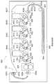
本発明のLEDプリントヘッドは、複数の半導体発光素子アレイと、前記複数の半導体発光素子アレイが配列された基板と、ロッドレンズアレイユニットと、前記ロッドレンズアレイユニットに備えられたロッドレンズアレイの焦点位置に、前記複数の半導体発光素子アレイの表面が位置するように、前記ロッドレンズアレイユニット及び前記基板を保持するフォルダとを有することを特徴とする。 The LED print head according to the present invention includes a plurality of semiconductor light emitting element arrays, a substrate on which the plurality of semiconductor light emitting element arrays are arranged, a rod lens array unit, and a focal point of the rod lens array provided in the rod lens array unit. The rod lens array unit and a folder for holding the substrate are arranged so that the surfaces of the plurality of semiconductor light emitting element arrays are located at positions.
本発明のイメージセンサヘッドは、半導体受光素子アレイと、前記複数の半導体受光素子アレイが配列された基板と、ロッドレンズアレイユニットと、前記ロッドレンズアレイユニットに備えられたロッドレンズアレイの焦点位置に、前記複数の半導体受光素子アレイの表面が位置するように、前記ロッドレンズアレイユニット及び前記基板を保持するフォルダとを有することを特徴とする。 The image sensor head of the present invention includes a semiconductor light receiving element array, a substrate on which the plurality of semiconductor light receiving element arrays are arranged, a rod lens array unit, and a focal position of the rod lens array provided in the rod lens array unit. The rod lens array unit and a folder for holding the substrate so that the surfaces of the plurality of semiconductor light receiving element arrays are positioned.
本発明の画像形成装置は、LEDプリントヘッドを有することを特徴とする。 The image forming apparatus of the present invention includes an LED print head.
本発明の画像読取装置は、イメージセンサヘッドを有することを特徴とする。 The image reading apparatus of the present invention has an image sensor head.
本発明のロッドレンズアレイユニットの製造方法は、複数のロッドレンズを含むロッドレンズアレイの第1の側面及び第2の側面に第1の側板及び第2の側板をそれぞれ接着剤で固定する工程と、前記第1の側板を貫通する第1の長溝を形成する工程と、前記第2の側板を貫通し、前記第1の長溝に重なる位置に第2の長溝を形成する工程と、前記第2の長溝内において、前記第1の長溝の幅及び前記第2の長溝の幅のいずれよりも狭い切断幅で前記第1の側板、前記第2の側板、及び前記ロッドレンズアレイを切断する工程と、を有することを特徴とする。 The method of manufacturing the rod lens array unit of the present invention includes a step of fixing the first side plate and the second side plate to the first side surface and the second side surface of the rod lens array including a plurality of rod lenses with an adhesive, respectively. Forming a first long groove penetrating through the first side plate, forming a second long groove at a position penetrating the second side plate and overlapping the first long groove, and the second Cutting the first side plate, the second side plate, and the rod lens array with a cutting width narrower than any of the width of the first long groove and the width of the second long groove. It is characterized by having.
本発明のロッドレンズアレイユニットによれば、安定した光学性能を実現することができる。 According to the rod lens array unit of the present invention, stable optical performance can be realized.
本発明のLEDプリントヘッドによれば、安定した光照射性能を実現することができる。 According to the LED print head of the present invention, stable light irradiation performance can be realized.
本発明のイメージセンサヘッドによれば、安定した受光性能を実現することができる。 According to the image sensor head of the present invention, stable light receiving performance can be realized.
本発明の画像形成装置によれば、安定した印字品質を実現することができる。 According to the image forming apparatus of the present invention, stable print quality can be realized.
本発明の画像読取装置によれば、安定した画像読取品質を実現することができる。 According to the image reading apparatus of the present invention, stable image reading quality can be realized.
本発明のロッドレンズアレイユニットの製造方法によれば、安定した光学性能を実現するロッドレンズアレイユニットの製造方法を提供することができる。 According to the method for manufacturing a rod lens array unit of the present invention, it is possible to provide a method for manufacturing a rod lens array unit that realizes stable optical performance.
《実施の形態1》
<ロッドレンズアレイユニット101の構成>
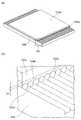
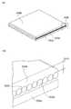
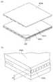
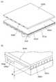
図1は、本発明の実施の形態1に係るロッドレンズアレイユニット101を示す斜視図である。図2は、図1に示されるロッドレンズアレイユニット101の一部の領域A1を示す拡大斜視図である。Embodiment 1
<Configuration of rod
FIG. 1 is a perspective view showing a rod
なお、図1及び図2に示されるロッドレンズアレイユニット101は、複数のロッドレンズ102aの各々の光軸を通る平面を対称面とする面対称の構造を有する。また、ロッドレンズアレイユニット101は、ロッドレンズアレイユニット101の短手方向(光軸方向)における両端側の構造が互いに同じであるので、一端側の構造のみを説明し他端側の構造の説明は省略する。 The rod
ロッドレンズアレイユニット101は、複数のロッドレンズ102aを含むロッドレンズアレイ102bと、ロッドレンズアレイ102bを間に挟んで積層された1対の側板部としての第1側板103a及び第2側板103bとを有する。ロッドレンズアレイ102bの光軸方向における第1側板103a及び第2側板103bの端面は、ロッドレンズアレイ102bの光軸方向におけるロッドレンズアレイ102bの端面よりも、ロッドレンズアレイ102bの光軸方向において内側に位置する。 The rod
ロッドレンズアレイ102bの端面は、第1主面102cを形成し、第1側板103a及び第2側板103bの各々の端面は、第2主面104cを形成する。第1主面102c及び第2主面104cは、ロッドレンズアレイ102bの光軸方向における両側に、それぞれ備えられており、第2主面104cは、第1主面102cよりも、光軸方向において内側に位置する。 The end surface of the
ロッドレンズアレイユニット101は、ロッドレンズアレイ102bが、第1側板103aと第2側板103bとの間において、ロッドレンズアレイ102bの側面と第1側板103a(第2側板103b)との間の距離である第1の距離D1が確保されるように、接着剤(充填接着剤)により固定された積層構造である。 The rod
ロッドレンズアレイユニット101は、第1側板103aと第2側板103bとの間に備えられ、ロッドレンズアレイ102bと第1側板103a及び第2側板103bとを固定する接着部102を有する。 The rod
接着部102は、第1の接着層としての充填接着層104を含む。充填接着層104は、ロッドレンズアレイ102bの周囲の空隙に第1の接着剤としての充填接着剤が充填された層である。充填接着層104は、第1充填接着層104a及び第2充填接着層104bを含む。 The
ロッドレンズアレイ102b及び接着部102は、第2主面104cよりも、ロッドレンズアレイ102bの光軸方向において外側に突出した突起部102dを形成する。突起部102dは、ロッドレンズアレイユニット101の短手方向における両端側にそれぞれ形成され、第1主面102cから第2主面104cまでの領域を含む。 The
図2に示されるように、第1主面102cは、ロッドレンズアレイユニット101の短手方向(ロッドレンズアレイ102bの光軸方向)における両端側において、ロッドレンズアレイ102bの端面を含む面であって、ロッドレンズアレイユニット101の長手方向に沿ってそれぞれ備えられた面である。 As shown in FIG. 2, the first
第2主面104cは、ロッドレンズアレイユニット101の短手方向における両端側において、ロッドレンズアレイユニット101の長手方向に沿ってそれぞれ備えられた面である。具体的には、第2主面104cは、ロッドレンズアレイユニット101の短手方向における充填接着層104の端面の一部と、ロッドレンズアレイユニット101の短手方向における第1側板103aの端面とを含む面である。第2主面104cは、ロッドレンズアレイユニット101の短手方向における充填接着層104の端面の一部と、ロッドレンズアレイユニット101の短手方向における第2側板103bの端面とを含む面でもある。第2主面104cの幅は、D2で示される。 The second
第1主面102cと第2主面104cとの境界は、第1の距離D1で示される範囲内に位置する。 The boundary between the first
第1主面102cと第2主面104cとの間の短手方向における距離(面間隔)は、第2の距離D3で示される。第2の距離D3が、D3>0であることにより、ロッドレンズアレイユニット101の短手方向における両側に段差部としての段差104dが形成されている。 A distance (surface interval) in the short direction between the first
ロッドレンズアレイユニット101の短手方向における両側にそれぞれ備えられた第1主面102c間の幅Z1は、ロッドレンズアレイユニット101の最終仕上がり幅である。 The width Z1 between the first
ロッドレンズアレイ102bの側面と第1側板103aとの間の距離である第1の距離D1、及びロッドレンズアレイ102bの側面と第2側板103bとの間の距離である第1の距離D1は、例えば、0.1mm≦D1≦1.0mmであることが望ましい。第2の距離D3は、例えば、0<D3≦1.0mmであることが望ましい。 A first distance D1 that is a distance between the side surface of the
複数のロッドレンズ102aが列状(アレイ状)に配列されたロッドレンズアレイ102bは、屈折率分布を有する。ロッドレンズ102aには、例えば、プラスチック素材が用いられ、メタクリレート(MMA)を含むアクリル樹脂、又はポリメチルメタクリレート(PMMA)等を用いることができる。なお、本明細書において、「列状」とは、直線状、曲線状、及び千鳥状等を含む。 The
第1側板103a及び第2側板103bには、被削性の低い材料が用いられ、例えば、ガラスクロスエポキシ樹脂、ガラス、セラミックス、フェノール樹脂、エポキシ樹脂、アクリル樹脂、及びABS樹脂(例えば、ガラスフィラーが添加されたABS樹脂)等を用いることができる。 A material having low machinability is used for the
本明細書において「被削性の低い材料」とは、ビッカース硬度が100HV以上である物質を含む材料のこという。なお、「被削性の低い材料」を「被削性の悪い材料」とも称する。 In this specification, “a material with low machinability” refers to a material containing a substance having a Vickers hardness of 100 HV or more. The “material with low machinability” is also referred to as “material with poor machinability”.
第1側板103a及び第2側板103bは、温度及び湿度による線膨張係数が小さいことが望ましい。具体的には、第1側板103a及び第2側板103bは、熱及び温度等による線膨張係数の値が、例えば、15ppm/℃以下であることが望ましい。第1側板103a及び第2側板103bは、吸水率が、例えば、0.1%以下であることが望ましい。 It is desirable that the
充填接着層104(第1充填接着層104a及び第2充填接着層104bを含む)を形成する充填接着剤には、例えば、シリコーン接着剤、エポキシ接着剤、又はウレタン接着剤等を用いることができる。本明細書において、「充填接着剤」は、第1充填接着剤及び第2充填接着剤を含む。 As the filling adhesive for forming the filling adhesive layer 104 (including the first
ただし、いずれの材料を用いた場合でも、第1の接着剤としての充填接着剤は、硬化収縮率が3%以下であることが望ましい。硬化収縮によって生じる応力によってロッドレンズアレイ102bの光学特性等の影響を低減するためである。また、第1充填接着層104a及び第2充填接着層104bは、吸水率が、例えば、0.1%以下であることが望ましい。 However, regardless of which material is used, it is desirable that the filling adhesive as the first adhesive has a cure shrinkage of 3% or less. This is to reduce the influence of the optical characteristics and the like of the
実施の形態1に係るロッドレンズアレイユニット101によれば、ロッドレンズアレイ102bの光軸方向における第1側板103a及び第2側板103bの端面は、ロッドレンズアレイ102bの光軸方向におけるロッドレンズアレイ102bの端面よりも、ロッドレンズアレイ102bの光軸方向において内側に位置することにより、ロッドレンズアレイ102bの周辺(例えば、第2主面104c)に付着した塵などがロッドレンズアレイ102bの端面に付着することを防ぎ、ロッドレンズアレイユニット101の安定した光学性能を実現することができる。 According to the rod
また、被削性の低い材料、又は温度及び湿度による線膨張係数が小さい材料を、第1側板103a及び第2側板103bに用いることにより、温度変化若しくは湿度変化などの使用環境(周辺環境)の変化、又は自己発熱による温度変化等に関わらず、寸法変動の小さいロッドレンズアレイユニット101を提供することができる。 In addition, by using a material with low machinability or a material with a low coefficient of linear expansion due to temperature and humidity for the
<ロッドレンズアレイユニット101の製造方法>
一般に、ロッドレンズアレイを構成するロッドレンズには、ガラス材料からなるレンズ、及びプラスチック材料からなるレンズがある。これらのロッドレンズを用いたロッドレンズアレイの製造工程において、所定の方向に配列された複数のロッドレンズの各々の光軸方向における先端の位置又は形状にばらつきが生じることがあるため、最終的に、ロッドレンズアレイの光軸方向におけるロッドレンズ部分の先端(端面)が一様に均されている必要がある。そのため、例えば、ガラス材料からなるロッドレンズを用いたロッドレンズアレイでは、ロッドレンズ部分の先端を研磨することにより、ロッドレンズ端面の仕上げが行われる。また、プラスチック材料からなるロッドレンズアレイでは、例えば、切削刃が備えられたリニア切削装置を用いてロッドレンズ先端を切削することにより、ロッドレンズ端面の仕上げが行われる。<Manufacturing Method of Rod
In general, the rod lenses constituting the rod lens array include a lens made of a glass material and a lens made of a plastic material. In the manufacturing process of the rod lens array using these rod lenses, the position or shape of the tip in the optical axis direction of each of the plurality of rod lenses arranged in a predetermined direction may vary. The tip (end face) of the rod lens portion in the optical axis direction of the rod lens array needs to be uniformly leveled. Therefore, for example, in a rod lens array using a rod lens made of a glass material, the end of the rod lens is finished by polishing the tip of the rod lens portion. Further, in a rod lens array made of a plastic material, for example, the end of the rod lens is finished by cutting the tip of the rod lens using a linear cutting device provided with a cutting blade.
リニア切削装置を用いてプラスチック材料のロッドレンズ先端を切削することにより行うレンズ断面の仕上げ方法は、ガラス材料のロッドレンズ部分の先端を研磨することにより行うロッドレンズ断面の仕上げ方法に比べて、製造工程を簡略化することができるため、プラスチック材料のロッドレンズを用いてロッドレンズアレイを製造することにより、ロッドレンズアレイの生産効率を高めることができる。しかしながら、リニア切削装置を用いてロッドレンズアレイのロッドレンズ先端を切削する場合、従来のロッドレンズアレイユニットの製造方法では、ロッドレンズアレイのロッドレンズ部分のみを切削することは困難であり、ロッドレンズ部分の周囲に配置された側板等も同時に切削せざるを得ない場合があった。したがって、ロッドレンズの周囲に配置される側板等は、リニア切削装置の切削刃に損傷を与えない材料で構成されていることが望まれる。 The lens cross-section finishing method performed by cutting the rod lens tip of plastic material using a linear cutting device is manufactured in comparison with the rod lens cross-section finishing method performed by polishing the tip of the rod lens portion of the glass material. Since the process can be simplified, the production efficiency of the rod lens array can be increased by manufacturing the rod lens array using a rod lens made of a plastic material. However, when the tip of the rod lens of the rod lens array is cut using a linear cutting device, it is difficult to cut only the rod lens portion of the rod lens array with the conventional method of manufacturing a rod lens array unit. In some cases, the side plates arranged around the portion have to be cut at the same time. Therefore, it is desirable that the side plate or the like disposed around the rod lens is made of a material that does not damage the cutting blade of the linear cutting device.
一方で、ロッドレンズの周囲に配置される側板には、例えば、フェノール樹脂、ABS樹脂、エポキシ樹脂、又はアクリル樹脂などの板材が用いられる。このような材料を側板に用いる場合、湿度変化又は温度変化などの使用環境の変化に伴ってロッドレンズアレイユニットの寸法変動が生じるという問題があった。 On the other hand, plate materials, such as a phenol resin, ABS resin, an epoxy resin, or an acrylic resin, are used for the side plate arrange | positioned around a rod lens, for example. When such a material is used for the side plate, there has been a problem that a dimensional variation of the rod lens array unit occurs with a change in usage environment such as a humidity change or a temperature change.
そこで、上記の<ロッドレンズアレイユニット101の構成>において説明したように、第1側板103a及び第2側板103bに、被削性の低い材料を用いることにより、湿度変化又は温度変化などの使用環境の変化に関わらず、ロッドレンズアレイユニット101の寸法変動を小さくすることが可能である。 Therefore, as described in the above <Configuration of rod
ただし、このようなロッドレンズアレイユニット101を製造する場合、リニア切削装置を用いたロッドレンズ端面の仕上げ工程において、切削刃が被削性の低い材料(例えば、ガラス材料が含まれた側板)に接触することにより損傷してしまうことを回避することが望まれる。そこで、次に、第1側板103a及び第2側板103bに、被削性の低い材料を用いた場合を考慮した、ロッドレンズアレイユニット101の製造方法について説明する。 However, when manufacturing such a rod
ロッドレンズアレイユニット101の製造方法は、複数のロッドレンズ102aを含むロッドレンズアレイ102bの第1の側面及び第2の側面と第1の側板としての第1側板103a及び第2の側板としての第2側板103bとをそれぞれ接着剤で固定する工程と、第1側板103aを貫通する第1の長溝としてのスリット107を形成する工程と、第2側板103bを貫通し、スリット107に重なる位置に第2の長溝としての他のスリット107を形成する工程と、第2の長溝としてのスリット107内において、第1の長溝の幅D6及び第2の長溝の幅D6のいずれよりも狭い切断幅D7で第1側板103a、第2側板103b、及びロッドレンズアレイ102bを切断する工程とを有する。
これらの工程について具体的に説明する。The manufacturing method of the rod
These steps will be specifically described.
<工程a1:第1充填接着剤塗布工程>
図3(a)は、実施の形態1に係るロッドレンズアレイユニット101の製造方法における第1充填接着剤塗布工程を示す図であり、図3(b)は、図3(a)に示される第1側板103a及び第1充填接着層104aの一部の領域A2を示す拡大斜視図である。<Step a1: First filling adhesive application step>
FIG. 3A is a diagram showing a first filling adhesive application step in the manufacturing method of the rod
図3(a)及び(b)に示されるように、第1側板103aの表面に第1充填接着剤を塗布して第1充填接着層104aを形成する。第1充填接着剤は、液状であることが望ましい。第1充填接着層104aの膜厚D4は、ロッドレンズアレイ102bの側面(複数のロッドレンズ102aの各々の側面)と第1側板103aとの間の距離(間隔)である第1の距離D1が確保されるように、第1の距離D1よりも厚く(長く)設定することが望ましい。また、第1充填接着層104aの膜厚D4は、ロッドレンズアレイ102bの外周面と第1側板103aとの間に空隙が発生しない程度の膜厚であることが望ましい。 As shown in FIGS. 3A and 3B, the first
<工程b1:ロッドレンズ配列工程>
図4(a)は、実施の形態1に係るロッドレンズアレイユニット101の製造方法におけるロッドレンズ配列工程を示す図であり、図4(b)は、図4(a)に示される配列基板105上に配列された複数のロッドレンズ102aの一部の領域A3を示す拡大斜視図である。<Step b1: Rod lens arrangement step>
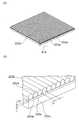
FIG. 4A is a diagram illustrating a rod lens array process in the method of manufacturing the rod
図4(a)及び(b)に示されるように、複数のロッドレンズ102aの配列ピッチPが一定となるように複数のグルーブ(溝)が形成された配列基板105上に、複数のロッドレンズ102aを並べる。配列基板105のグルーブは、例えば、アルミニウム又はガラスを主要な材料とする基板を、ロッドレンズ102aの形状及び寸法を考慮して切削、又はエッチングすることにより作製することができる。 As shown in FIGS. 4A and 4B, a plurality of rod lenses are formed on the
複数のロッドレンズ102aを、複数のロッドレンズ102aの各々の光軸方向に直交する方向に配列することにより、ロッドレンズアレイ102bを得ることができる。 The
<工程c1:ロッドレンズ接着工程>
図5(a)は、実施の形態1に係るロッドレンズアレイユニット101の製造方法におけるロッドレンズ接着工程を示す図であり、図5(b)は、図5(a)に示される第1充填接着層104aに接着された複数のロッドレンズ102aの一部の領域A3を示す拡大斜視図である。<Step c1: Rod lens bonding step>
FIG. 5A is a diagram showing a rod lens bonding step in the method of manufacturing the rod
第1側板103aにおいて第1充填接着層104aが形成された面を、配列基板105上に配列された複数のロッドレンズ102a(ロッドレンズアレイ102b)の側面(第1の側面)に密着させて、ロッドレンズアレイ102bを第1充填接着層104aに接着させる。 The surface on which the first
ロッドレンズアレイ102bを第1充填接着層104aに接着させる際、例えば、プレス機を用いて第1側板103aをプレスして、第1充填接着層104aとロッドレンズアレイ102bとをプレス接着させる。プレス接着する際、ロッドレンズアレイ102bと第1側板103aの内面との間の第1の距離D1が確保されるように、荷重コントロール及び位置決めを行い、プレス接着することが望ましい。 When the
第1充填接着層104aの粘度が、例えば、10[Pa・s]以下などの低い粘度である場合、この工程c1において、第1充填接着層104aの粘度を高めるため、又は第1充填接着層104aを硬化させるため、第1充填接着層104aを予備加熱してもよい。第1充填接着層104aの粘度を高めることにより、又は第1充填接着層104aを硬化させることにより、後の工程において第1の距離D1及びピッチPの変動を抑制することができる。 When the viscosity of the first
<工程d1:ロッドレンズ転写工程>
図6(a)は、実施の形態1に係るロッドレンズアレイユニット101の製造方法におけるロッドレンズ転写工程を示す図であり、図6(b)は、図6(a)に示される第1側板103a及び第1充填接着層104a上に固定されたロッドレンズアレイ102bの一部の領域A5を示す拡大斜視図である。<Step d1: Rod lens transfer step>
6A is a view showing a rod lens transfer step in the method of manufacturing the rod
配列基板105から、ロッドレンズアレイ102bが固定された第1側板103aを引き上げることで、配列基板105から第1充填接着層104a上にロッドレンズアレイ102bを移動(転写)させる。後の工程で第1の距離D1、又はピッチPの変動を抑制するため、この工程d1において第1充填接着層104aを予備加熱してもよい。 The
<工程e1:第2充填接着剤塗布工程>
図7(a)は、実施の形態1に係るロッドレンズアレイユニット101の製造方法における第2充填接着剤塗布工程を示す図であり、図7(b)は、図7(a)に示されるロッドレンズアレイ102b上に形成された第2充填接着層104bの一部の領域A6を示す拡大斜視図である。<Step e1: Second filling adhesive application step>
FIG. 7A is a diagram showing a second filling adhesive application step in the method of manufacturing the rod
工程d1により得られたロッドレンズアレイ102bの側面(第2の側面)に、第2充填接着剤を塗布して第2充填接着層104bを形成する。第2充填接着剤は、液状であることが望ましい。第2充填接着層104bの膜厚D5は、後工程(工程f1:第2側板接着工程)において、第2側板103bとロッドレンズアレイ102bとを固定する際、ロッドレンズアレイ102bと第2側板103bとの間の第1の距離D1が確保されるように、第1の距離D1よりも厚く(長く)設定することが望ましい。また、第2充填接着層104bの膜厚D5は、ロッドレンズアレイ102bと第2側板103bとの間に空隙が発生しない程度の膜厚であることが望ましい。 A second
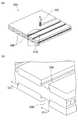
<工程f1:第2側板接着工程>
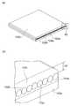
図8(a)は、実施の形態1に係るロッドレンズアレイユニット101の製造方法における第2側板接着工程を示す図であり、図8(b)は、図8(a)に示されるロッドレンズアレイシート100の一部の領域A7を示す拡大斜視図である。<Step f1: Second side plate bonding step>
FIG. 8A is a diagram showing a second side plate bonding step in the method of manufacturing the rod
工程f1では、第2充填接着層104bと第2側板103bの側面とを接着させることにより、ロッドレンズアレイシート100を作製する。 In step f1, the rod
第2側板103bと第2充填接着層104bとを接着させる際、ロッドレンズアレイ102bと第2側板103bの内面との間の第1の距離D1が確保されるように、荷重コントロール及び位置決めを行い、プレス接着することが望ましい。第2充填接着層104bの粘度が、例えば、10[Pa・s]以下などの低い粘度である場合、この工程f1において、第2充填接着層104bの粘度を高めるため、又は第2充填接着層104bを硬化させるため、第2充填接着層104bを予備加熱してもよい。第2充填接着層104bの粘度を高めることにより、第1の距離D1の変動を抑制することができる。 When bonding the
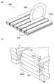
<工程g1:スリット形成工程>
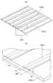
図9(a)は、実施の形態1に係るロッドレンズアレイユニット101の製造方法におけるスリット形成工程を示す図であり、図9(b)は、図9(a)に示されるロッドレンズアレイシート100の一部の領域A8を示す拡大斜視図である。<Step g1: Slit formation step>
FIG. 9A is a view showing a slit forming step in the manufacturing method of the rod
例えば、エンドミル106を用いて、ロッドレンズアレイシート100の両面(第1側板103a及び第2側板103bの表面)に、スリット幅D6、且つ、深さD2の複数のスリット107を形成する。複数のスリット107のピッチ(幅Z2)が、ロッドレンズアレイ102bの光軸方向と平行な方向に沿って一定になるように、複数のスリット107を形成する。スリット幅D6は、ロッドレンズアレイ102bの光軸方向と平行な方向における長さを示す。深さD2は、ロッドレンズアレイ102bの光軸方向と直交する方向における長さを示す。 For example, the
スリット幅D6は、後工程(工程h1:切断工程)においてロッドレンズアレイシート100を切断する際の切断幅である幅D7よりも長くなるように設定する。スリット幅D6の中心位置は、後工程(工程h1:切断工程)におけるロッドレンズアレイシート100の切断位置である。 The slit width D6 is set to be longer than the width D7, which is a cutting width when the rod
深さD2は、スリット107内において少なくとも第1側板103a及び第2側板103bを完全に切削する(貫通する)深さであり、且つ、ロッドレンズアレイ102bの表面に損傷を与えない程度の深さに設定すればよい。言い換えると、深さD2は、スリット107の底部が、第1の距離D1の範囲内に位置する深さに設定すればよい。 The depth D2 is a depth that completely cuts (penetrates) at least the
幅Z2は、後工程(工程h1:切断工程)においてロッドレンズアレイ102bの光軸方向における端面を切削仕上げするための幅D8を考慮して決定すればよい。 The width Z2 may be determined in consideration of the width D8 for cutting and finishing the end surface in the optical axis direction of the
<工程h1:切断工程>
図10(a)は、実施の形態1に係るロッドレンズアレイユニット101の製造方法における切断工程を示す図であり、図10(b)は、図10(a)に示される切断されたロッドレンズアレイシート100aの一部の領域A9を示す拡大斜視図である。<Step h1: Cutting step>
FIG. 10A is a diagram illustrating a cutting process in the method of manufacturing the rod
例えば、ダイシングソー108を用いて、工程g1で形成したスリット幅D6の中心位置において切断幅がスリット幅D6よりも狭い幅D7となるようにロッドレンズアレイシート100を切断する。ロッドレンズアレイシート100を切断することにより、ロッドレンズアレイ102bの光軸方向における両端面(断面)が形成される。幅D7は、後工程(工程i1:切削工程)においてロッドレンズアレイ102bの光軸方向における端面を幅D8だけ切削する際に、後述するカッターホイール109の先端に固定された切削刃110が、第1側板103a及び第2側板103bと接触しない幅(長さ)に設定すればよい。 For example, using the dicing saw 108, the rod
<工程i1:切削工程>
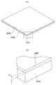
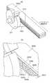
図11(a)は、実施の形態1に係るロッドレンズアレイユニット101の製造方法における切削工程を示す図であり、図11(b)は、図11(a)に示される切断されたロッドレンズアレイシート100aの一部の領域A10を示す拡大斜視図である。<Process i1: Cutting process>
FIG. 11A is a diagram showing a cutting process in the manufacturing method of the rod
工程h1で形成されたロッドレンズアレイ102bの光軸方向における両端面(断面)を、例えば、切削刃110を用いて、幅D8だけ切削してロッドレンズアレイ102bの光軸方向における両端面の鏡面仕上げを行う。ロッドレンズアレイ102bの光軸方向における両端面の鏡面仕上げを行うことにより、ロッドレンズアレイユニット101の短手方向における幅Z1が決定される。幅D8は、最終仕上がり時における幅Z1を考慮して決定すればよい。 Both end surfaces (cross-sections) in the optical axis direction of the
以上の工程により、ロッドレンズアレイユニット101が完成する。以上に説明したロッドレンズアレイユニット101の製造方法では、1つのロッドレンズアレイユニット101において複数のロッドレンズ102aを主走査方向(複数のロッドレンズ102aの各々の光軸方向と直交する方向)に1列配列する場合を例として説明したが、複数のロッドレンズ102aの列の数は1列に限定されない。 The rod
例えば、主走査方向に2列のロッドレンズアレイ102bを積層する場合は、工程a1から工程d1で説明した方法と同様に1列目として配列される複数のロッドレンズ102aを第1充填接着層104a上に接着させ、さらに、2列目として配列される複数のロッドレンズ102aを1列目の複数のロッドレンズ102a上に配列する。2列目の複数のロッドレンズ102aを1列目の複数のロッドレンズ102a上に配列する場合、1列目の複数のロッドレンズ102aと2列目の複数のロッドレンズ102aとが主走査方向において互いにP/2だけずれて配列されるように、2列目の複数のロッドレンズ102aを1列目の複数のロッドレンズ102a上に積層すればよい。 For example, when two rows of
2列目の複数のロッドレンズ102aを1列目の複数のロッドレンズ102a上に配列した後、工程e1と同様に2列目の複数のロッドレンズ102a上に第2充填接着層104bを形成し、2列目の複数のロッドレンズ102a間の空隙を第2充填接着層104bで充填する。この積層構造を硬化接着するため、第2充填接着層104bを加熱処理及び加湿処理のいずれか、又はその両方の処理をしてもよい。その後の工程は、工程f1から工程i1と同様の処理を行えばよい。 After arranging the plurality of
実施の形態1に係るロッドレンズアレイユニット101の製造方法によれば、ロッドレンズアレイ102bと第1側板103a及び第2側板103bとの間に、第1の距離D1が確保された充填接着層104を形成することにより、第1側板103a及び第2側板103bにおけるスリット加工(工程g1)の際、ロッドレンズアレイ102bの側面に損傷を与えることを抑制することができる。 According to the manufacturing method of the rod
ロッドレンズアレイユニット101に、温度及び湿度による線膨張係数の小さな材料、又は被削性の低い材料を含む第1側板103a及び第2側板103bを用いる場合であっても、ロッドレンズアレイユニット101の光軸方向における第1側板103a及び第2側板103bの各々における両端面が、その光軸方向におけるロッドレンズアレイ102bの両端面よりも、その光軸方向において内側に位置するようにスリット加工(工程g1)を行うので、ロッドレンズアレイ102bの光軸方向における両端面の鏡面仕上げ(工程i1)を行う際、切削装置(例えば、リニア切削装置)における切削刃の損傷を抑制することができる。
《実施の形態2》
<ロッドレンズアレイユニット201の構成>
図12は、本発明の実施の形態2に係るロッドレンズアレイユニット201を示す斜視図である。図13は、図12に示されるロッドレンズアレイユニット201の一部の領域A11を示す拡大斜視図である。Even when the rod
<< Embodiment 2 >>
<Configuration of rod
FIG. 12 is a perspective view showing a rod
なお、図12及び図13に示されるロッドレンズアレイユニット201は、複数のロッドレンズ202aの各々の光軸を通る平面を対称面とする面対称の構造を有する。また、ロッドレンズアレイユニット201は、ロッドレンズアレイユニット201の短手方向における両端側の構造が互いに同じであるので、一端側の構造のみを説明し他端側の構造の説明は省略する。 The rod
ロッドレンズアレイユニット201は、複数のロッドレンズ202aを含むロッドレンズアレイ202bと、ロッドレンズアレイ202bを間に挟んで積層された1対の側板部としての第1側板203a及び第2側板203bとを有する。ロッドレンズアレイ202bの光軸方向における第1側板203a及び第2側板203bの端面は、ロッドレンズアレイ202bの光軸方向におけるロッドレンズアレイ202bの端面よりも、ロッドレンズアレイ202bの光軸方向において内側に位置する。 The rod
ロッドレンズアレイ202bの端面は、第1主面202cを形成し、第1側板203a及び第2側板203bの各々の端面は、第2主面204cを形成する。第1主面202c及び第2主面204cは、ロッドレンズアレイ202bの光軸方向における両側に、それぞれ備えられており、第2主面204cは、第1主面202cよりも、ロッドレンズアレイ202bの光軸方向において内側に位置する。 The end surface of the
ロッドレンズアレイユニット201は、第2の接着層としての側面接着層205a(第1側面接着層)及び第2の接着層としての側面接着層205b(第2側面接着層)が、充填接着層204(第1充填接着層204a)と第1側板203aとの間、及び充填接着層204(第2充填接着層204b)と第2側板203bとの間においてそれぞれ積層された積層構造である。側面接着層205a及び205bは、第2の接着剤からなり、第2の接着剤の硬化前粘度は、充填接着層204を形成する第1の接着剤の硬化前粘度よりも高い。なお、図12及び図13に示される例では、ロッドレンズアレイ202bの両側面は、それぞれ側面接着層205a及び205bに接着されている。 The rod
ロッドレンズアレイユニット201は、第1側板203aと第2側板203bとの間に備えられ、ロッドレンズアレイ202bと第1側板203a及び第2側板203bとを固定する接着部202を有する。 The rod
接着部202は、第1の接着層としての充填接着層204と、第2の接着層としての側面接着層205a及び205bを含む。充填接着層204は、ロッドレンズアレイ202bの周囲の空隙に第1の接着剤としての充填接着剤が充填された層である。充填接着層204は、第1充填接着層204a及び第2充填接着層204bを含む。側面接着層205aは、充填接着層204(第1充填接着層204a)と第1側板203aとの間に備えられ、充填接着層204(第1充填接着層204a)と第1側板203aとを固定する。側面接着層205bは、充填接着層204(第2充填接着層204b)と第2側板203bとの間に備えられ、充填接着層204(第2充填接着層204b)と第2側板203bとを固定する。 The
ロッドレンズアレイ202b及び接着部202は、第2主面204cよりも、ロッドレンズアレイ202bの光軸方向において外側に突出した突起部202dを形成する。突起部202dは、ロッドレンズアレイユニット201の短手方向における両端側にそれぞれ形成され、第1主面202cから第2主面204cまでの領域を含む。 The
図13に示されるように、第1主面202cは、ロッドレンズアレイユニット201の短手方向(ロッドレンズアレイ202bの光軸方向)における両端側において、ロッドレンズアレイ202bの端面を含む面であって、ロッドレンズアレイユニット201の長手方向に沿ってそれぞれ備えられた面である。 As shown in FIG. 13, the first
第2主面204cは、ロッドレンズアレイユニット201の短手方向における両端側において、ロッドレンズアレイユニット201の長手方向に沿ってそれぞれ備えられた面である。具体的には、第2主面204cは、ロッドレンズアレイユニット201の短手方向における側面接着層205aの端面の一部と、ロッドレンズアレイユニット201の短手方向における第1側板203aの端面とを含む面である。第2主面204cは、ロッドレンズアレイユニット201の短手方向における側面接着層205bの端面の一部と、ロッドレンズアレイユニット201の短手方向における第2側板203bの端面とを含む面でもある。第2主面204cの幅は、D2で示される。 The second
第1主面202cと第2主面204cとの境界は、ロッドレンズアレイ202bの側面と第1側板203a(第2側板203b)との間の距離である第1の距離D1で示される範囲内に位置する。 The boundary between the first
第1主面202cと第2主面204cとの間の短手方向における距離(面間隔)は、第2の距離D3で示される。第2の距離D3が、D3>0であることにより、ロッドレンズアレイユニット201の短手方向における両側に段差部としての段差204dが形成されている。 A distance (surface interval) in the short direction between the first
複数のロッドレンズ202aが列状に配列されたロッドレンズアレイ202bは、屈折率分布を有する。ロッドレンズ202aには、例えば、プラスチック素材が用いられる。 A
側面接着層205a及び205bを形成する材料としては、例えば、液状若しくはドライフィルム状の、シリコーン接着剤、エポキシ接着剤、又はウレタン接着剤等を用いることができる。側面接着層205a及び205bを形成する接着剤は、充填接着層204を形成する接着剤と比較して硬化前粘度が高いことが望ましく、例えば、硬化前粘度が10[Pa・s]以上であることが望ましい。膜厚D1は、例えば、0.1mmから1.0mmの範囲の厚さにすることができる。ロッドレンズアレイユニット201における側面接着層205a及び205b以外の構成要素の材料は、実施の形態1において対応する構成要素に用いられる材料を用いることができる。 As a material for forming the side
実施の形態2に係るロッドレンズアレイユニット201によれば、ロッドレンズアレイ202bの光軸方向における第1側板203a及び第2側板203bの端面は、ロッドレンズアレイ202bの光軸方向におけるロッドレンズアレイ202bの端面よりも、ロッドレンズアレイ202bの光軸方向において内側に位置することにより、ロッドレンズアレイ202bの周辺(例えば、第2主面204c)に付着した塵などがロッドレンズアレイ202bの端面に付着することを防ぎ、ロッドレンズアレイユニット201の安定した光学性能を実現することができる。 According to the rod
また、被削性の低い材料、又は温度及び湿度による線膨張係数が小さい材料を、第1側板203a及び第2側板203bに用いることにより、温度変化若しくは湿度変化などの使用環境(周辺環境)の変化、又は自己発熱による温度変化等に関わらず、寸法変動の小さいロッドレンズアレイユニット201を提供することができる。 In addition, by using a material with low machinability or a material with a low coefficient of linear expansion due to temperature and humidity for the
<ロッドレンズアレイユニット201の製造方法>
次に、ロッドレンズアレイユニット201の製造方法について説明する。
ロッドレンズアレイユニット201の製造方法は、複数のロッドレンズ202aを含むロッドレンズアレイ202bの第1の側面及び第2の側面と第1の側板としての第1側板203a及び第2の側板としての第2側板203bとをそれぞれ接着剤で固定する工程と、第1側板203aを貫通する第1の長溝を形成する工程と、第2側板203bを貫通し、第1の長溝に重なる位置に第2の長溝を形成する工程と、第2の長溝内において、第1の長溝の幅及び第2の長溝の幅のいずれよりも狭い切断幅で第1側板203a、第2側板203b、及びロッドレンズアレイ202bを切断する工程とを有する。<Method for Manufacturing Rod
Next, a method for manufacturing the rod
The manufacturing method of the rod
ロッドレンズアレイユニット201の製造方法は、ロッドレンズアレイ202bに第1の接着剤(第1充填接着剤及び第2充填接着剤)を塗布する工程と、第1側板203a及び第2側板203bに第2の接着剤を塗布する工程とをさらに有する。
これらの工程について具体的に説明する。The manufacturing method of the rod
These steps will be specifically described.
<工程a2:第1側面接着層形成工程>
図14(a)は、実施の形態2に係るロッドレンズアレイユニット201の製造方法における第1側面接着層形成工程を示す図であり、図14(b)は、図14(a)に示される側面接着層205aが形成された第1側板203aの一部の領域A12を示す拡大斜視図である。<Step a2: First side surface adhesive layer forming step>
FIG. 14A is a diagram showing a first side surface adhesive layer forming step in the method of manufacturing the rod
図14(a)及び(b)に示されるように、第1側板203a上に、液状の接着剤(第2の接着剤)を塗布、又はドライフィルム状の接着剤(第2の接着剤)をラミネートすることにより、膜厚D1からなる側面接着層205a(第1側面接着層)を形成する。 As shown in FIGS. 14A and 14B, a liquid adhesive (second adhesive) is applied on the
<工程b2:第1充填接着剤塗布工程>
図15(a)は、実施の形態2に係るロッドレンズアレイユニット201の製造方法における第1充填接着剤塗布工程を示す図であり、図15(b)は、図15(a)に示される第1側板203a及び側面接着層205a上に形成された第1充填接着層204aの一部の領域A13を示す拡大斜視図である。<Step b2: First filling adhesive application step>
FIG. 15A is a diagram showing a first filling adhesive application step in the manufacturing method of the rod
工程a2で得られた第1側板203aにおける側面接着層205a上に、第1の接着剤としての第1充填接着剤を塗布して第1充填接着層204aを形成する。第1充填接着剤は液状であることが望ましい。第1充填接着層204aの膜厚D4は、後工程(工程d2:ロッドレンズ接着工程)においてロッドレンズアレイ202bと側面接着層205aとの間に空隙が生じない程度の膜厚であることが望ましい。 A first
<工程c2:ロッドレンズ配列工程>
図16(a)は、実施の形態2に係るロッドレンズアレイユニット201の製造方法におけるロッドレンズ配列工程を示す図であり、図16(b)は、図16(a)に示される配列基板206上に配列された複数のロッドレンズ202aの一部の領域A14を示す拡大斜視図である。<Process c2: Rod lens arrangement process>
FIG. 16A is a diagram illustrating a rod lens array process in the method of manufacturing the rod
図16(a)及び(b)に示されるように、複数のロッドレンズ202aの配列ピッチPが一定となるように複数のグルーブ(溝)が形成された配列基板206上に、複数のロッドレンズ202aを並べる。配列基板206のグルーブは、例えば、アルミニウム又はガラスを主要な材料とする基板を、ロッドレンズ202aの形状及び寸法を考慮して切削、又はエッチングすることにより作製することができる。 As shown in FIGS. 16A and 16B, a plurality of rod lenses are formed on an
<工程d2:ロッドレンズ接着工程>
図17(a)は、実施の形態2に係るロッドレンズアレイユニット201の製造方法におけるロッドレンズ接着工程を示す図であり、図17(b)は、図17(a)に示される第1充填接着層204aに接着された複数のロッドレンズ202aの一部の領域A15を示す拡大斜視図である。<Step d2: Rod lens bonding step>
FIG. 17A is a diagram showing a rod lens bonding step in the method of manufacturing the rod
第1側板203aにおいて第1充填接着層204aが形成された面を、配列基板206上に並べられた複数のロッドレンズ202a(ロッドレンズアレイ202b)に密着させて、第1充填接着剤をロッドレンズアレイ202bの周囲の空隙に充填させ、側面接着層205aとロッドレンズアレイ202bの側面(第1の側面)とが当接するようにプレス接着する。 The surface on which the first
プレス接着する際、ロッドレンズアレイ202bと第1側板203aとの間において、スペーサとしての側面接着層205aによって形成される第1の距離D1が確保されるように、荷重コントロール及び位置決めを行い、プレス接着することが望ましい。 During press bonding, load control and positioning are performed so that a first distance D1 formed by the side
第1充填接着層204aの粘度が、例えば、10[Pa・s]以下などの低い粘度である場合、この工程d2において、第1充填接着層204aの粘度を高めるため、又は第1充填接着層204aを硬化させるため、第1充填接着層204aを予備加熱してもよい。第1充填接着層204aの粘度を高めることにより、又は第1充填接着層204aを硬化させることにより、後の工程において配列ピッチPが変動してしまうことを抑制することができる。 When the viscosity of the first
<工程e2:ロッドレンズ転写工程>
図18(a)は、実施の形態2に係るロッドレンズアレイユニット201の製造方法におけるロッドレンズ転写工程を示す図であり、図18(b)は、図18(a)に示される第1側板203a及び側面接着層205a上に固定されたロッドレンズアレイ202bの一部の領域A16を示す拡大斜視図である。<Step e2: Rod lens transfer step>
FIG. 18A is a diagram illustrating a rod lens transfer process in the method of manufacturing the rod
配列基板206から、ロッドレンズアレイ202bが固定された第1側板203aを引き上げることで、配列基板206から側面接着層205a上にロッドレンズアレイ202bを移動(転写)させる。後の工程で配列ピッチPの変動を抑制するため、この工程e2において第1充填接着層204a又は側面接着層205aを予備加熱してもよい。 The
<工程f2:第2充填接着剤塗布工程>
図19(a)は、実施の形態2に係るロッドレンズアレイユニット201の製造方法における第2充填接着剤塗布工程を示す図であり、図19(b)は、図19(a)に示されるロッドレンズアレイ202b上に形成された第2充填接着層204bの一部の領域A17を示す拡大斜視図である。<Step f2: Second filling adhesive application step>
FIG. 19A is a diagram showing a second filling adhesive application step in the manufacturing method of the rod
工程e2により得られたロッドレンズアレイ202bの側面(第2の側面)に、第1の接着剤としての第2充填接着剤を塗布して第2充填接着層204bを形成する。第2充填接着剤は、液状であることが望ましい。第2充填接着層204bの塗布厚D5は、後工程(工程h2:第2側板接着工程)において第2側板203bとロッドレンズアレイ202bとを固定する際、ロッドレンズアレイ202bと側面接着層205bとの間に空隙が発生しない程度の膜厚であることが望ましい。 A second
<工程g2:第2側面接着層形成工程>
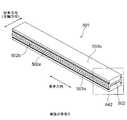
図20(a)は、実施の形態2に係るロッドレンズアレイユニット201の製造方法における第2側面接着層形成工程を示す図であり、図20(b)は、図20(a)に示される側面接着層205bが形成された第2側板203bの一部の領域A18を示す拡大斜視図である。<Step g2: Second side surface adhesive layer forming step>
FIG. 20A is a diagram showing a second side surface adhesive layer forming step in the method of manufacturing the rod
図20(a)及び(b)に示されるように、第2側板203b上に、液状の接着剤(第2の接着剤)を塗布、又はドライフィルム状の接着剤(第2の接着剤)をラミネートすることにより、膜厚D1からなる側面接着層205b(第2側面接着層)を形成する。 As shown in FIGS. 20A and 20B, a liquid adhesive (second adhesive) is applied to the
<工程h2:第2側板接着工程>
図21(a)は、実施の形態2に係るロッドレンズアレイユニット201の製造方法における第2側板接着工程を示す図であり、図21(b)は、図21(a)に示されるロッドレンズアレイシート200の一部の領域A19を示す拡大斜視図である。<Step h2: Second side plate bonding step>
FIG. 21A is a diagram showing a second side plate bonding step in the method of manufacturing the rod
工程h2では、第2充填接着層204bと、第2側板203b上の側面接着層205bとを接着させることにより、ロッドレンズアレイシート200を作製する。具体的には、工程f2により得られた第2充填接着層204bと、第2側板203bにおける側面接着層205bが備えられた面とを対向させて、側面接着層205bがロッドレンズアレイ202bに当接するように第2側板203bをプレス(プレス接着)する。プレス接着により、第1充填接着剤及び第2充填接着剤がロッドレンズアレイ202bの周囲に充填され、第1側板203a及び第2側板203bの第2の接着剤が塗布された面により、第1充填接着剤及び第2充填接着剤が充填されたロッドレンズアレイ202bを挟んで固定する。 In step h2, the rod
プレス接着する際、ロッドレンズアレイ202bと第2側板203bの内面との間において、スペーサとしての側面接着層205bによって形成される第1の距離D1が確保されるように、荷重コントロール及び位置決めを行い、プレス接着することが望ましい。工程h2を完了した後、工程h2において得られた積層構造(ロッドレンズアレイシート200)を加熱処理及び加湿処理のいずれか、又はその両方の処理をすることにより、硬化接着させる。 When press bonding, load control and positioning are performed so that a first distance D1 formed by the side surface
さらに、実施の形態1で説明した<工程g1:スリット形成工程>、<工程h1:切断工程>、及び<工程i1:切削工程>における処理と同様の処理を実施して、ロッドレンズアレイユニット201を製造することができる。 Further, the rod
なお、実施の形態1におけるスリット形成工程において、ロッドレンズアレイユニット101のスリットの深さD2は、スリット107の底部が、第1充填接着層104a又は第2充填接着層104bの範囲内に位置する深さに設定したが、実施の形態2におけるスリット形成工程では、ロッドレンズアレイユニット201に形成するスリットの深さは、スリットの底部が、側面接着層(すなわち、側面接着層205a又は205b)の範囲内に位置する深さに設定する。 In the slit forming step in the first embodiment, the slit depth D2 of the rod
以上の工程により、ロッドレンズアレイユニット201が完成する。以上に説明したロッドレンズアレイユニット201の製造方法では、1つのロッドレンズアレイユニット201において複数のロッドレンズ202aを主走査方向(複数のロッドレンズ202aの各々の光軸方向と直交する方向)に1列配列する場合を例として説明したが、複数のロッドレンズ202aの列の数は1列に限定されない。 The rod
例えば、主走査方向に2列のロッドレンズアレイ202bを積層する場合は、工程a2から工程e2で説明した方法に基づいて、1列目として配列される複数のロッドレンズ202aを側面接着層205a上に配列し、同様に、2列目として配列される複数のロッドレンズ202aを側面接着層205b上に配列する。1列目の複数のロッドレンズ202aと2列目の複数のロッドレンズ202aとが主走査方向において互いにP/2だけずれて配列されるように、側面接着層205a上のロッドレンズアレイ202bと側面接着層205b上のロッドレンズアレイ202bとを対向させて、互いのロッドレンズアレイ202bの間に充填接着剤を充填して、2列のロッドレンズアレイ202bを積層すればよい。 For example, when two rows of
実施の形態2に係るロッドレンズアレイユニット201の製造方法によれば、ロッドレンズアレイ202bと第1側板203a及び第2側板203bとの間に、第1の距離D1を確保することにより、第1側板203a及び第2側板203bにおけるスリット加工の際、ロッドレンズアレイ202bの側面に損傷を与えることを抑制することができる。 According to the manufacturing method of the rod
ロッドレンズアレイユニット201に、温度及び湿度による線膨張係数の小さな材料、又は被削性の低い材料を含む第1側板203a及び第2側板203bを用いる場合であっても、ロッドレンズアレイユニット201の光軸方向における第1側板203a及び第2側板203bの各々における両端面が、その光軸方向におけるロッドレンズアレイ202bの両端面よりも、その光軸方向において内側に位置するようにスリット加工を行うので、ロッドレンズアレイ202bの光軸方向における両端面の鏡面仕上げを行う際、切削装置(例えば、リニア切削装置)における切削刃の損傷を抑制することができる。 Even when the
第1充填接着層204aと第1側板203aとの間に、第1充填接着層204aを形成する接着剤よりも粘性(粘度)の高い接着剤を用いて側面接着層205aを形成するので、ロッドレンズアレイ202bと第1側板203aとを固定する際、第1側板203a上の第1充填接着層204a及び側面接着層205aの変動を低減し、ロッドレンズアレイ202bの配置を安定して行うことができる。 Since the side
《実施の形態3》
<ロッドレンズアレイユニット301の構成>
図22は、本発明の実施の形態3に係るロッドレンズアレイユニット301を示す斜視図である。図23は、図22に示されるロッドレンズアレイユニット301の一部の領域A20を示す拡大斜視図である。<< Embodiment 3 >>
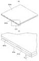
<Configuration of rod
FIG. 22 is a perspective view showing a rod
なお、図22及び図23に示されるロッドレンズアレイユニット301は、複数のロッドレンズ302aの各々の光軸を通る平面を対称面とする面対称の構造を有する。また、ロッドレンズアレイユニット301は、ロッドレンズアレイユニット301の短手方向における両端側の構造が互いに同じであるので、一端側の構造のみを説明し他端側の構造の説明は省略する。 The rod
ロッドレンズアレイユニット301は、複数のロッドレンズ302aを含むロッドレンズアレイ302bと、ロッドレンズアレイ302bを間に挟んで積層された1対の側板部としての第1側板303a及び第2側板303bとを有する。ロッドレンズアレイ302bの光軸方向における第1側板303a及び第2側板303bの端面は、ロッドレンズアレイ302bの光軸方向におけるロッドレンズアレイ302bの端面よりも、ロッドレンズアレイ302bの光軸方向において内側に位置する。 The rod
ロッドレンズアレイ302bの端面は、第1主面302cを形成し、第1側板303a及び第2側板303bの各々の端面は、第2主面304cを形成する。第1主面302c及び第2主面304cは、ロッドレンズアレイ302bの光軸方向における両側に、それぞれ備えられており、第2主面304cは、第1主面302cよりも、ロッドレンズアレイ302bの光軸方向において内側に位置する。 The end surface of the
ロッドレンズアレイユニット301は、第1側板303aと第2側板303bとの間に備えられ、ロッドレンズアレイ302bと第1側板303a及び第2側板303bとを固定する接着部302を有する。 The rod
接着部302は、第1の接着層としての充填接着層304を含む。充填接着層304は、ロッドレンズアレイ302bの周囲の空隙に第1の接着剤としての充填接着剤が充填された層である。充填接着層304は、第1充填接着層304a及び第2充填接着層304bを含む。 The
第1側板303aは、ロッドレンズアレイ302bの光軸方向における第1側板303aのロッドレンズアレイ302bに面する側の端部に切り欠き303cを有する。同様に、第2側板303bは、ロッドレンズアレイ302bの光軸方向における第2側板303bのロッドレンズアレイ302bに面する側の端部に切り欠き303cを有する。切り欠き303cは、第1側板303a及び第2側板303bの短手方向における端部において、ロッドレンズアレイユニット301の長手方向に沿って形成されている。切り欠き303cには、充填接着層304(第1充填接着層304a又は第2充填接着層304b)が備えられている。 The
ロッドレンズアレイ302b及び接着部302は、第2主面304cよりも、ロッドレンズアレイ302bの光軸方向において外側に突出した突起部302dを形成する。突起部302dは、ロッドレンズアレイユニット301の短手方向における両端側にそれぞれ形成され、第1主面302cから第2主面304cまでの領域を含む。 The
図23に示されるように、第1主面302cは、ロッドレンズアレイユニット301の短手方向(ロッドレンズアレイ302bの光軸方向)における両端側において、ロッドレンズアレイ302bの端面を含む面であって、ロッドレンズアレイユニット301の長手方向に沿ってそれぞれ備えられた面である。 As shown in FIG. 23, the first
第2主面304cは、ロッドレンズアレイユニット301の短手方向における両端側において、ロッドレンズアレイユニット301の長手方向に沿ってそれぞれ備えられた面である。具体的には、第2主面304cは、ロッドレンズアレイユニット301の短手方向における充填接着層304の端面の一部と、ロッドレンズアレイユニット301の短手方向における第1側板303aの端面とを含む面である。第2主面304cは、ロッドレンズアレイユニット301の短手方向における充填接着層304の端面の一部と、ロッドレンズアレイユニット301の短手方向における第2側板303bの端面とを含む面でもある。第2主面304cの幅は、D2で示される。 The second
第1主面302cと第2主面304cとの境界は、ロッドレンズアレイ302bの側面と第1側板303a(第2側板303b)との間の距離である第1の距離D1で示される範囲内に位置する。 The boundary between the first
第1主面302cと第2主面304cとの間の短手方向における距離(面間隔)は、第2の距離D3で示される。第2の距離D3が、D3>0であることにより、ロッドレンズアレイユニット301の短手方向における両側に段差部としての段差304dが形成されている。 A distance (surface interval) in the short direction between the first
第1側板303a及び第2側板303bにおいて、第1主面302cからの距離D5の領域に、深さD4のトレンチが形成され、そのトレンチに充填接着層304が充填されていることにより、ロッドレンズアレイ302bの側面と第2側板303b(第1側板303a)との間の距離である第1の距離D1と深さD4の関係は、D1>D4となり、第1の距離D1を確保することができる。 In the
第2主面304cの幅D2、すなわち、第1主面302cと第2主面304cとの境界位置は、第1側板303a(第2側板303b)の内面とロッドレンズアレイ302bの側面との間に位置することが望ましい。 The width D2 of the second
図23に示される例では、ロッドレンズアレイ302bの側面と第2側板303b(第1側板303a)の内面との距離D9がD9>0であるが、ロッドレンズアレイ302bの側面が第1側板303a及び第2側板303bと当接されていてもよい。すなわち、ロッドレンズアレイ302bの側面と第2側板303b(第1側板303a)の内面との距離D9がD9=0であってもよい。 In the example shown in FIG. 23, the distance D9 between the side surface of the
ロッドレンズアレイユニット301の短手方向における両側にそれぞれ備えられた第1主面302c間の幅Z1は、ロッドレンズアレイユニット301の最終仕上がり幅である。 The width Z1 between the first
ロッドレンズアレイユニット301における構成要素の材料は、実施の形態1において対応する構成要素に用いられる材料を用いることができる。 As the material of the component in the rod
実施の形態3に係るロッドレンズアレイユニット301によれば、ロッドレンズアレイ302bの光軸方向における第1側板303a及び第2側板303bの端面は、ロッドレンズアレイ302bの光軸方向におけるロッドレンズアレイ302bの端面よりも、ロッドレンズアレイ302bの光軸方向において内側に位置することにより、ロッドレンズアレイ302bの周辺(例えば、第2主面304c)に付着した塵などがロッドレンズアレイ302bの端面に付着することを防ぎ、ロッドレンズアレイユニット301の安定した光学性能を実現することができる。 According to the rod
また、被削性の低い材料、又は温度及び湿度による線膨張係数が小さい材料を、第1側板303a及び第2側板303bに用いることにより、温度変化若しくは湿度変化などの使用環境(周辺環境)の変化、又は自己発熱による温度変化等に関わらず、寸法変動の小さいロッドレンズアレイユニット301を提供することができる。 In addition, by using a material with low machinability or a material with a low coefficient of linear expansion due to temperature and humidity for the
<ロッドレンズアレイユニット301の製造方法>
次に、ロッドレンズアレイユニット301の製造方法について説明する。
ロッドレンズアレイユニット301の製造方法は、複数のロッドレンズ302aを含むロッドレンズアレイ302bの第1の側面及び第2の側面と第1の側板としての第1側板303a及び第2の側板としての第2側板303bとをそれぞれ接着剤で固定する工程と、第1側板303aを貫通する第1の長溝としてのスリット308を形成する工程と、第2側板303bを貫通し、スリット308に重なる位置に第2の長溝としての他のスリット308を形成する工程と、第2の長溝としてのスリット308内において、第1の長溝の幅D10及び第2の長溝の幅D10のいずれよりも狭い切断幅D11で第1側板303a、第2側板303b、及びロッドレンズアレイ302bを切断する工程とを有する。<Method for Manufacturing Rod
Next, a manufacturing method of the rod
The manufacturing method of the rod
ロッドレンズアレイユニット301の製造方法は、第1の側板としての第1側板303aに第3の長溝としてのトレンチ305を形成し、第2の側板としての第2側板303bに第4の長溝としての他のトレンチ305を形成する工程と、ロッドレンズアレイ302bの周囲に第1の接着剤を塗布する工程とをさらに有する。
これらの工程について具体的に説明する。In the manufacturing method of the rod
These steps will be specifically described.
<工程a3:第1及び第2側板内面トレンチ加工工程>
図24(a)は、実施の形態3に係るロッドレンズアレイユニット301の製造方法における第1及び第2側板内面トレンチ加工工程を示す図であり、図24(b)は、図24(a)に示される第1側板303aの一部の領域A21を示す拡大斜視図である。<Step a3: First and second side plate inner surface trench processing step>
FIG. 24A is a view showing first and second side plate inner surface trench processing steps in the method of manufacturing the rod
工程a3では、第1側板303a及び第2側板303bのそれぞれにトレンチ305を形成する。なお、図24(a)及び(b)には、トレンチ305が形成される第1側板303aのみが示される。 In step a3, a
図24(a)及び(b)に示されるように、第1側板303aの表面に幅D7、且つ、深さD4の複数のトレンチ305をピッチZ2で形成する。トレンチ305が形成された面は、ロッドレンズアレイユニット301における内面である。 As shown in FIGS. 24A and 24B, a plurality of
トレンチ305は、例えば、エンドミルを用いて形成することができる。トレンチ幅D7は、後述の工程(工程i3:切断工程)において形成される切断幅D11、及び後述の工程(工程j3:切削工程)において形成される切削幅D12を考慮して設定することが望ましい。なお、深さD4は、例えば、0.1mmから1.0mmの範囲とすることができる。ピッチZ2は、後述の工程(工程i3:切断工程)において形成される切断幅D11、及び後述の工程(工程j3:切削工程)において形成される切削幅D12を考慮して、最終的な仕上げ幅であるZ1よりも広い幅に設定する。 The
<工程b3:第1充填接着剤塗布工程>
図25(a)は、実施の形態3に係るロッドレンズアレイユニット301の製造方法における第1充填接着剤塗布工程を示す図であり、図25(b)は、図25(a)に示される第1側板303a及び第1充填接着層304aの一部の領域A22を示す拡大斜視図である。<Step b3: First filling adhesive application step>
FIG. 25A is a diagram showing a first filling adhesive application step in the manufacturing method of the rod
図25(a)及び(b)に示されるように、第1側板303aのトレンチ305が形成された表面にトレンチ305を埋めるように第1の接着剤としての第1充填接着剤を塗布して第1充填接着層304aを形成する。第1充填接着剤は、液状であることが望ましい。第1充填接着層304aの膜厚D8は、ロッドレンズアレイ302bの側面(複数のロッドレンズ302aの各々の側面)と第1側板303aとの間の距離D9が確保されるように、距離D9よりも厚く(長く)設定することが望ましい。また、第1充填接着層304aの膜厚D8は、ロッドレンズアレイ302bと第1側板303aとの間、及びロッドレンズアレイ302bと第1側板303aに内面に形成したトレンチ305との間のそれぞれにおいて空隙が発生しない程度の膜厚であることが望ましい。 As shown in FIGS. 25A and 25B, a first filling adhesive as a first adhesive is applied so as to fill the
<工程c3:ロッドレンズ配列工程>
図26(a)は、実施の形態3に係るロッドレンズアレイユニット301の製造方法におけるロッドレンズ配列工程を示す図であり、図26(b)は、図26(a)に示される配列基板306上に配列された複数のロッドレンズ302aの一部の領域A23を示す拡大斜視図である。<Step c3: Rod lens arrangement step>
FIG. 26A is a diagram showing a rod lens array process in the manufacturing method of the rod
図26(a)及び(b)に示されるように、複数のロッドレンズ302aの配列ピッチPが一定となるように複数のグルーブ(溝)が形成された配列基板306上に、複数のロッドレンズ302aを並べる。配列基板306のグルーブは、例えば、アルミニウム又はガラスを主要な材料とする基板を、ロッドレンズ302aの形状及び寸法を考慮して切削、又はエッチングすることにより作製することができる。 As shown in FIGS. 26A and 26B, a plurality of rod lenses are arranged on an
<工程d3:ロッドレンズ接着工程>
図27(a)は、実施の形態3に係るロッドレンズアレイユニット301の製造方法におけるロッドレンズ接着工程を示す図であり、図27(b)は、図27(a)に示される第1充填接着層304aに接着された複数のロッドレンズ302aの一部の領域A24を示す拡大斜視図である。<Step d3: Rod lens bonding step>
FIG. 27A is a diagram showing a rod lens bonding step in the method of manufacturing the rod
第1側板303aにおいて第1充填接着層304aが形成された面を、配列基板306上に配列された複数のロッドレンズ302a(ロッドレンズアレイ302b)に密着させて、ロッドレンズアレイ302bの側面(第1の側面)を第1充填接着層304a上に接着させる。 The surface of the
ロッドレンズアレイ302bを第1充填接着層304a上に接着させる際、例えば、プレス機を用いて第1側板303aをプレスして、第1充填接着層304aとロッドレンズアレイ302bとをプレス接着させる。プレス接着する際、ロッドレンズアレイ302bと第1側板303aの内面(トレンチ305が形成されている部分以外の内面)との間の距離D9が確保されるように、荷重コントロール及び位置決めを行い、プレス接着することが望ましい。 When the
第1充填接着層304aの粘度が、例えば、10[Pa・s]以下などの低い粘度である場合、この工程d3において、第1充填接着層304aの粘度を高めるため、又は第1充填接着層304aを硬化させるため、第1充填接着層304aを予備加熱してもよい。第1充填接着層304aの粘度を高めることにより、又は第1充填接着層304aを硬化させることにより、後の工程において距離D9及びピッチPの変動を抑制することができる。 When the viscosity of the first
<工程e3:ロッドレンズ転写工程>
図28(a)は、実施の形態3に係るロッドレンズアレイユニット301の製造方法におけるロッドレンズ転写工程を示す図であり、図28(b)は、図28(a)に示される第1側板303a及び第1充填接着層304a上に固定されたロッドレンズアレイ302bの一部の領域A25を示す拡大斜視図である。<Process e3: Rod lens transfer process>
FIG. 28A is a diagram showing a rod lens transfer step in the method of manufacturing the rod
配列基板306から、ロッドレンズアレイ302bが固定された第1側板303aを引き上げることで、配列基板306から第1充填接着層304a上にロッドレンズアレイ302bを移動(転写)させる。後の工程で距離D9、又は配列ピッチPの変動を抑制するため、この工程e3において第1充填接着層304aを予備加熱することもできる。 The
<工程f3:第2充填接着剤塗布工程>
図29(a)は、実施の形態3に係るロッドレンズアレイユニット301の製造方法における第2充填接着剤塗布工程を示す図であり、図29(b)は、図29(a)に示されるロッドレンズアレイ302b上に形成された第2充填接着層304bの一部の領域A26を示す拡大斜視図である。<Step f3: Second filling adhesive application step>
FIG. 29A is a diagram showing a second filling adhesive application step in the manufacturing method of the rod
工程e3により得られたロッドレンズアレイ302bの周囲(第2の側面を含む)に、第1の接着剤としての第2充填接着剤を塗布して第2充填接着層304bを形成する。第2充填接着剤は、液状であることが望ましい。第2充填接着層304bの膜厚D13は、後述の工程(工程g3:第2側板接着工程)において、第2側板303bとロッドレンズアレイ302bとを固定する際、ロッドレンズアレイ302bと第2側板303bとの間の距離D9が確保されるように、距離D9よりも厚く(長く)設定することが望ましい。また、第2充填接着層304bの膜厚D13は、ロッドレンズアレイ302bと第2側板303bとの間、及びロッドレンズアレイ302bと第2側板303bの内面に形成されたトレンチ305との間において、それぞれ空隙が発生しない程度の膜厚であることが望ましい。 A second
<工程g3:第2側板接着工程>
図30(a)は、実施の形態3に係るロッドレンズアレイユニット301の製造方法における第2側板接着工程を示す図であり、図30(b)は、図30(a)に示されるロッドレンズアレイシート300の一部の領域A27を示す拡大斜視図である。<Step g3: Second side plate bonding step>
FIG. 30 (a) is a diagram showing a second side plate bonding step in the method of manufacturing the rod
図30(a)及び(b)に示されるように、工程g3では、第2充填接着層304bと第2側板303bとを接着させることにより、ロッドレンズアレイシート300を作製する。 As shown in FIGS. 30A and 30B, in step g3, the rod filling
第2充填接着層304bと第2側板303bとを接着させる際、例えば、プレス機を用いて第2側板303bをプレスして、第2充填接着層304bとロッドレンズアレイ302bとをプレス接着させる。プレス接着することにより、第1側板303a及び第2側板303bの充填接着剤(第1充填接着剤及び第2充填接着剤)が塗布された面でロッドレンズアレイ302bを挟むようにして、第1側板303aとロッドレンズアレイ302bと第2側板303bとを重ねて固定することができる。 When bonding the second
プレス接着する際、ロッドレンズアレイ302bと第2側板303bの内面(トレンチ305が形成されている部分以外の内面)との間の距離D9が確保されるように、荷重コントロール及び位置決めを行い、プレス接着することが望ましい。第2充填接着層304bの粘度が、例えば、10[Pa・s]以下などの低い粘度である場合、この工程g3において、第2充填接着層304bの粘度を高めるため、又は第2充填接着層304bを硬化させるため、第2充填接着層304bを予備加熱してもよい。第2充填接着層304bの粘度を高めることにより、距離D9の変動を抑制することができる。 When press bonding, load control and positioning are performed so that a distance D9 is secured between the
<工程h3:スリット形成工程>
図31(a)は、実施の形態3に係るロッドレンズアレイユニット301の製造方法におけるスリット形成工程を示す図であり、図31(b)は、図31(a)に示されるロッドレンズアレイシート300の一部の領域A28を示す拡大斜視図である。<Process h3: Slit formation process>
FIG. 31 (a) is a diagram showing a slit forming step in the manufacturing method of the rod
例えば、エンドミル307を用いて、ロッドレンズアレイシート300の両面(第1側板303a及び第2側板303bの表面)に、幅D10、且つ、深さD2の複数のスリット308を形成する。複数のスリット308のピッチ(幅Z2)が、ロッドレンズアレイ302bの光軸方向と平行な方向に沿って一定になるように、複数のスリット308を形成する。第1側板303a及び第2側板303bにおいて、スリット308は、第1側板303a及び第2側板303bに形成されているトレンチ305に重なる位置に形成する。 For example, using the
スリット幅D10は、ロッドレンズアレイ302bの光軸方向と平行な方向における長さを示す。深さD2は、ロッドレンズアレイ302bの光軸方向と直交する方向における長さを示す。 The slit width D10 indicates the length in the direction parallel to the optical axis direction of the
深さD2は、スリット308内において少なくとも第1側板303a及び第2側板303bを完全に切削する(貫通する)深さであり、且つ、ロッドレンズアレイ302bの表面に損傷を与えない程度の深さに設定すればよい。言い換えると、深さD2は、スリット308の底部が、第1の距離D1の範囲内に位置する深さに設定すればよい。 The depth D2 is a depth that completely cuts (penetrates) at least the
スリット308の幅D10は、後述の工程(工程i3:切断工程)においてロッドレンズアレイシート300を切断する際の切断幅である幅D11よりも長くなるように設定する。また、スリット308の幅D10は、後述の工程(工程j3:切削工程)においてロッドレンズアレイ302bの光軸方向における端面を切削仕上げ(鏡面仕上げ)するための幅D12を考慮し、切削刃311が第1側板303a及び第2側板303bと接触しない幅となるように設定すればよい。 The width D10 of the
<工程i3:切断工程>
図32(a)は、実施の形態3に係るロッドレンズアレイユニット301の製造方法における切断工程を示す図であり、図32(b)は、図32(a)に示される切断されたロッドレンズアレイシート300aの一部の領域A29を示す拡大斜視図である。<Process i3: Cutting process>
FIG. 32A is a diagram illustrating a cutting process in the method of manufacturing the rod
図32(a)及び(b)に示されるように、例えば、ダイシングソー309を用いて、工程h3で形成したスリット308の幅D10の中心線を、スリット幅D10よりも狭い幅D11(切断幅)で切断する。 As shown in FIGS. 32A and 32B, for example, using a dicing saw 309, the center line of the width D10 of the
<工程j3:切削工程>
図33(a)は、実施の形態3に係るロッドレンズアレイユニット301の製造方法における切削工程を示す図であり、図33(b)は、図33(a)に示される切断されたロッドレンズアレイシート300aの一部の領域A30を示す拡大斜視図である。<Process j3: Cutting process>
FIG. 33 (a) is a diagram showing a cutting process in the manufacturing method of the rod
図33(a)及び(b)に示されるように、例えば、カッターホイール310の先端に固定した切削刃311を用いて、ロッドレンズアレイ302bの光軸方向における端面を、切削幅D12だけ切削することでレンズ断面の鏡面仕上げを行う。ロッドレンズアレイ302bの光軸方向における両端面の鏡面仕上げを行うことにより、ロッドレンズアレイユニット301の光軸方向における幅Z1(最終仕上げ幅)が決定される。 As shown in FIGS. 33A and 33B, for example, the end face in the optical axis direction of the
以上の工程により、ロッドレンズアレイユニット301が完成する。以上に説明したロッドレンズアレイユニット301の製造方法では、1つのロッドレンズアレイユニット301において複数のロッドレンズ302aを主走査方向(複数のロッドレンズ302aの各々の光軸方向と直交する方向)に1列配列する場合を例として説明したが、複数のロッドレンズ302aの列の数は1列に限定されない。 The rod
例えば、主走査方向に2列のロッドレンズアレイ302bを積層する場合は、工程b3から工程e3で説明した方法と同様に、1列目の複数のロッドレンズ302aと2列目の複数のロッドレンズ302aとが主走査方向において互いにP/2だけずれて配列されるように、1列目の複数のロッドレンズ302aと2列目の複数のロッドレンズ302aとを積層し、1列目の複数のロッドレンズ302aと2列目の複数のロッドレンズ302aとの間に充填接着剤を充填してプレス接着すればよい。 For example, when two rows of
実施の形態3に係るロッドレンズアレイユニット301の製造方法によれば、第1側板303a及び第2側板303bの表面にトレンチ305を形成し、トレンチ305の深さD4を調整することにより、第1の距離D1を実施の形態1に比べて長く確保することができるので、第1側板303a及び第2側板303bにおけるスリット加工(工程h3)における工程マージン(加工マージン)を確保することができ、ロッドレンズアレイ302bの側面に損傷を与えることを、実施の形態1に比べてさらに抑制することができる。 According to the method of manufacturing the rod
ロッドレンズアレイ302bの側面を第1側板303a及び第2側板303bに当接させて固定した場合であっても、ロッドレンズアレイ302bと第1側板303aとの間、及びロッドレンズアレイ302bと第2側板303bとの間に、トレンチ305を形成することにより、トレンチ305の深さD4に基づく第1の距離D1を確保することができるので、第1側板303a及び第2側板303bにおけるスリット加工(工程h3)における工程マージン(加工マージン)を確保することができ、ロッドレンズアレイ302bの側面に損傷を与えることを抑制することができる。 Even when the side surface of the
ロッドレンズアレイユニット301に、温度及び湿度による線膨張係数の小さな材料、又は被削性の低い材料を含む第1側板303a及び第2側板303bを用いる場合であっても、ロッドレンズアレイユニット301の光軸方向における第1側板303a及び第2側板303bの各々における両端面が、その光軸方向におけるロッドレンズアレイ302bの両端面よりも、その光軸方向において内側に位置するようにスリット加工(工程h3)を行うので、ロッドレンズアレイ302bの光軸方向における両端面の鏡面仕上げ(工程j3)を行う際、切削装置(例えば、リニア切削装置)における切削刃の損傷を抑制することができる。 Even if the rod
《実施の形態4》
<ロッドレンズアレイユニット401の構成>
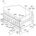
図34は、本発明の実施の形態4に係るロッドレンズアレイユニット401を示す斜視図である。図35は、図34に示されるロッドレンズアレイユニット401の一部の領域A31を示す拡大斜視図である。<< Embodiment 4 >>
<Configuration of Rod
FIG. 34 is a perspective view showing a rod
なお、図34及び図35に示されるロッドレンズアレイユニット401は、複数のロッドレンズ402aの各々の光軸を通る平面を対称面とする面対称の構造を有する。また、ロッドレンズアレイユニット401は、ロッドレンズアレイユニット401の短手方向における両端側の構造が互いに同じであるので、一端側の構造のみを説明し他端側の構造の説明は省略する。 Note that the rod
ロッドレンズアレイユニット401は、複数のロッドレンズ402aを含むロッドレンズアレイ402bと、ロッドレンズアレイ402bを間に挟んで積層された1対の側板部としての第1側板403a及び第2側板403bとを有する。ロッドレンズアレイ402bの光軸方向における第1側板403a及び第2側板403bの端面は、ロッドレンズアレイ402bの光軸方向におけるロッドレンズアレイ402bの端面よりも、ロッドレンズアレイ402bの光軸方向において内側に位置する。 The rod
ロッドレンズアレイ402bの端面は、第1主面402cを形成し、第1側板403a及び第2側板403bの各々の端面は、第2主面404cを形成する。第1主面402c及び第2主面404cは、ロッドレンズアレイ402bの光軸方向における両側に、それぞれ備えられており、第2主面404cは、第1主面402cよりも、ロッドレンズアレイ402bの光軸方向において内側に位置する。 The end surface of the
ロッドレンズアレイユニット401は、第1側板403aと第2側板403bとの間において、ロッドレンズアレイ402bの側面と第1側板403a(第2側板403b)との間の距離である第1の距離W1が確保されるように、ロッドレンズアレイ402bと、充填接着層404と、第1側壁層405a及び第2側壁層405bとが積層された積層構造である。 The rod
ロッドレンズアレイユニット401は、第1側板403aと第2側板403bとの間に備えられ、ロッドレンズアレイ402bと第1側板403a及び第2側板403bとを固定する接着部402を有する。 The rod
接着部402は、充填接着層404と、第3の接着層としての第1側壁層405a(第1充填接着層側壁層)及び第3の接着層としての第2側壁層405b(第2充填接着層側壁層)を含む。なお、第1側壁層405a及び第2側壁層405bをまとめて「側壁層」と称する。充填接着層404は、ロッドレンズアレイ402bの周囲の空隙に第1の接着剤としての充填接着剤が充填された層である。充填接着層404は、第1充填接着層404a及び第2充填接着層404bを含む。 The
ロッドレンズアレイ402b及び接着部402は、第2主面404cよりも、ロッドレンズアレイ402bの光軸方向において外側に突出した突起部402dを形成する。突起部402dは、ロッドレンズアレイユニット401の短手方向における両端側にそれぞれ形成され、第1主面402cから第2主面404cまでの領域を含む。 The
第1側壁層405a及び第2側壁層405bは、突起部402dの側面、及びに備えられる。また、図35に示されるように、第1側壁層405a及び第2側壁層405bは、接着部402の両端側であって、第1側板403a及び第2側板403bに対向する位置に備えられていてもよい。 The
図35に示されるように、第1主面402cは、ロッドレンズアレイユニット401の短手方向(ロッドレンズアレイ402bの光軸方向)における両端側において、ロッドレンズアレイ402bの端面を含む面であって、ロッドレンズアレイユニット401の長手方向に沿ってそれぞれ備えられた面である。 As shown in FIG. 35, the first
第2主面404cは、ロッドレンズアレイユニット401の短手方向における両端側において、ロッドレンズアレイユニット401の長手方向に沿ってそれぞれ備えられた面である。具体的には、第2主面404cは、ロッドレンズアレイユニット401の短手方向における第1側壁層405aの端面の一部と、ロッドレンズアレイユニット401の短手方向における第1側板403aの端面とを含む面である。第2主面404cは、ロッドレンズアレイユニット401の短手方向における第2側壁層405bの端面の一部と、ロッドレンズアレイユニット401の短手方向における第2側板403bの端面とを含む面でもある。第2主面404cの幅は、W2で示される。 The second
第1主面402cと第2主面404cとの境界は、第1の距離W1で示される範囲内に位置する。 The boundary between the first
第1主面402cと第2主面404cとの間の短手方向における距離(面間隔)は、第2の距離W3で示される。第2の距離W3が、W3>0であることにより、ロッドレンズアレイユニット401の短手方向における両側に段差部としての段差404dが形成されている。 A distance (surface interval) in the short direction between the first
第1側壁層405aは、第1側板403aと第1充填接着層404aとの間に備えられ、第1側壁層405aの膜厚はt2で示される。第2側壁層405bは、第2側板403bと第2充填接着層404bとの間に備えられ、第2側壁層405bの膜厚は第1側壁層405aと同じ(膜厚t2)である。 The
第1側壁層405a及び第2側壁層405bの短手方向における幅は、W5で示される。ロッドレンズアレイユニット401の短手方向における両側にそれぞれ備えられた第1主面402c間の幅W4は、ロッドレンズアレイユニット401の最終仕上がり幅である。 The width in the lateral direction of the
ロッドレンズ402aには、例えば、メタクリレート(MMA)を含むアクリル樹脂、又はポリメチルメタクリレート(PMMA)等を用いることができる。 For the
第1側板403a及び第2側板403bには、被削性の低い材料が用いられ、例えば、ガラスクロスエポキシ樹脂、ガラス、セラミックス、フェノール樹脂、エポキシ樹脂、アクリル樹脂、及びABS樹脂(例えば、ガラスフィラーが添加されたABS樹脂)等を用いることができる。 For the
第1側板403a及び第2側板403bは、温度及び湿度による線膨張係数が小さいことが望ましい。第1側板403a及び第2側板403bは、熱による線膨張係数の値が、例えば、15ppm/℃以下であることが望ましい。第1側板403a及び第2側板403bは、吸水率が、例えば、0.1%以下であることが望ましい。 It is desirable that the
充填接着層404(第1充填接着層404a及び第2充填接着層404bを含む)を形成する充填接着剤(第1充填接着層及び第2充填接着層を含む)には、例えば、シリコーン接着剤、エポキシ接着剤、又はウレタン接着剤等を用いることができる。ただし、いずれの材料を用いた場合でも、第1の接着剤としての充填接着剤は、硬化収縮率が3%以下であることが望ましい。硬化収縮によって生じる応力によってロッドレンズアレイ402bの光学特性等の影響を低減するためである。また、第1充填接着層404a及び第2充填接着層404bは、吸水率が、例えば、0.1%以下であることが望ましい。 Examples of the filling adhesive (including the first filling adhesive layer and the second filling adhesive layer) for forming the filling adhesive layer 404 (including the first
第1側壁層405a及び第2側壁層405bは、充填接着層404よりも引張弾性率が高いことが望ましい。第1側壁層405a及び第2側壁層405bには、例えば、エポキシ樹脂、アクリル樹脂、又はウレタン樹脂等を用いることができる。ただし、第1側壁層405a及び第2側壁層405bは、いずれの材料を用いた場合でも、硬い材料であることが望ましく、例えば、硬化後の引張弾性率が1GPa以上であることが望ましい。ロッドレンズアレイユニット401の製造時において、第1側壁層405a及び第2側壁層405bの材料を塗布した直後に、膜厚、及び幅等の形状を保つ必要があるため、第1側壁層405a及び第2側壁層405bの材料の粘度は、1[Pa・s]以上であることが望ましい。ただし、粘度が高いことにより、膜厚t2を均一に形成することが困難な場合は、材料の塗布後にスキージを用いて膜厚を均すこともできる。 The
第1の距離W1は、例えば、0.1mm≦W1≦1.0mmであることが望ましい。第1主面402cと第2主面404cとの間の短手方向における第2の距離W3(面間隔)は、例えば、0<W3≦1.0mmであることが望ましい。 The first distance W1 is preferably 0.1 mm ≦ W1 ≦ 1.0 mm, for example. The second distance W3 (surface distance) in the short direction between the first
第1側壁層405a及び第2側壁層405bの膜厚t2は、例えば、0.1mm≦t2<1.0mmであることが望ましく、ロッドレンズアレイ402bへの引張応力の影響を防ぐため、ロッドレンズアレイ402bと第1側壁層405aとは互いに接触しないことが望ましい。同様に、ロッドレンズアレイ402bと第2側壁層405bとは互いに接触しないことが望ましい。 The film thickness t2 of the first
実施の形態4に係るロッドレンズアレイユニット401によれば、ロッドレンズアレイ402bの光軸方向における第1側板403a及び第2側板403bの端面は、ロッドレンズアレイ402bの光軸方向におけるロッドレンズアレイ402bの端面よりも、ロッドレンズアレイ402bの光軸方向において内側に位置することにより、ロッドレンズアレイ402bの周辺(例えば、第2主面404c)に付着した塵などがロッドレンズアレイ402bの端面に付着することを防ぎ、ロッドレンズアレイユニット401の安定した光学性能を実現することができる。 According to the rod
ロッドレンズアレイ402bの突起部402dの側面は、引張弾性率が高い材料を含む第1側壁層405a及び第2側壁層405bにより形成され、比較的硬く、且つ破損しにくい構造を有することにより、突起部402dを外部からの衝撃等によるダメージから保護することができる。 The side surface of the
また、被削性の低い材料、又は温度及び湿度による線膨張係数が小さい材料を、第1側板403a及び第2側板403bに用いることにより、温度変化若しくは湿度変化などの使用環境(周辺環境)の変化、又は自己発熱による温度変化等に関わらず、寸法変動の小さいロッドレンズアレイユニット401を提供することができる。 In addition, by using a material with low machinability or a material with a low coefficient of linear expansion due to temperature and humidity for the
<ロッドレンズアレイユニット401の製造方法>
次に、ロッドレンズアレイユニット401の製造方法について説明する。
ロッドレンズアレイユニット401の製造方法は、複数のロッドレンズ402aを含むロッドレンズアレイ402bの第1の側面及び第2の側面と第1の側板としての第1側板403a及び第2の側板としての第2側板403bとをそれぞれ接着剤で固定する工程と、第1側板403aを貫通する第1の長溝としてのスリット408を形成する工程と、第2側板403bを貫通し、スリット408に重なる位置に第2の長溝としての他のスリット408を形成する工程と、第2の長溝としてのスリット408内において、第1の長溝の幅W7及び第2の長溝の幅W7のいずれよりも狭い切断幅W9で第1側板403a、第2側板403b、及びロッドレンズアレイ402bを切断する工程とを有する。<Method for Manufacturing Rod
Next, a method for manufacturing the rod
The manufacturing method of the rod
ロッドレンズアレイユニット401の製造方法は、第1側板403a及び第2側板403bに、第3の接着剤としての第1充填接着層側壁剤及び第3の接着剤としての第2充填接着層側壁剤をそれぞれ塗布する工程と、ロッドレンズアレイ402bの周囲に第1の接着剤を塗布する工程とをさらに有する。
これらの工程について具体的に説明する。The manufacturing method of the rod
These steps will be specifically described.
<工程a4:第1及び第2充填接着層側壁剤塗布工程>
図36(a)は、実施の形態4に係るロッドレンズアレイユニット401の製造方法における第1及び第2充填接着層側壁剤塗布工程を示す図であり、図36(b)は、図36(a)に示される第1側板403aの一部の領域A32を示す拡大斜視図である。<Step a4: first and second filling adhesive layer side wall agent coating step>
FIG. 36 (a) is a diagram showing the first and second filling adhesive layer side wall agent coating steps in the manufacturing method of the rod
工程a4では、第1側板403aに第1側壁層405aを形成し、第2側板403bに第2側壁層405bを形成する。なお、図36(a)及び(b)には、第1側壁層405aが形成される第1側板403aのみが示される。 In step a4, the first
第1側板403a上に、第3の接着剤としての第1充填接着層側壁剤を塗布して、膜厚t2、且つ、幅W6である複数の第1側壁層405a(第1充填接着層側壁層)をピッチP2で形成する。第1充填接着層側壁剤としては、例えば、エポキシ樹脂、アクリル樹脂、又はウレタン樹脂等を用いることができる。 A first filling adhesive layer sidewall agent as a third adhesive is applied onto the
第1側壁層405aの膜厚t2は後述工程(工程h4:スリット形成工程)において、第1側板403a及び第2側板403bの表面にスリット加工を行う際、膜厚t2の領域内で加工を収めるに十分な膜厚である必要がある。また、幅W6は、後述工程(工程h4:スリット形成工程)において第1側板403a及び第2側板403bの表面にスリット加工を行う際、スリット幅よりも十分広い幅である必要がある。 The film thickness t2 of the first
ただし、第1側板403aの全面に第1充填接着層側壁剤を塗布した場合、第1側壁層405aの硬化収縮による応力により、第1側板403aが応力変形を引き起こす要因となる。したがって、後工程において切削されるロッドレンズアレイ402bの端面近傍のみに第1充填接着層側壁剤を塗布することが望ましい。 However, when the first filling adhesive layer side wall agent is applied to the entire surface of the
ピッチP2は、後述工程(工程i4:切断工程)において、ロッドレンズアレイ402bを切断するピッチを考慮して設定する。第1側壁層405aは、上記のように膜厚t2及び幅W6となる形状を確保するため、1〔Pa・s〕以上の粘度であることが望ましい。膜厚t2を均一に形成することが因難な場合は、スキージを用いて膜厚を均一に形成することもできる。 The pitch P2 is set in consideration of the pitch at which the
工程a4で形成する第1側壁層405aと、後述工程(工程b4:第1充填接着剤塗布工程及び工程f4:第2充填接着剤塗布工程)において形成する第1充填接着層404a及び第2充填接着層404bの溶剤とが混ざり合わないようにするために、工程a4において第1側壁層405aを硬化させておくことが望ましい。 The first
図36(a)及び(b)では、ロッドレンズアレイユニット401のうちの1つの側壁層(第1側壁層405a)についての作製方法のみが示されているが、第1側壁層405aとは異なる第2側壁層405b(第2充填接着層側壁層)についても、第1側壁層405aの作製方法と同様の方法で作製する。第2側壁層405bは、第2側板403b上に、第3の接着剤としての第2充填接着層側壁剤を塗布して作製する。第2充填接着層側壁剤としては、第1充填接着層側壁剤と同様の材料を用いることができる。 36 (a) and 36 (b) show only a manufacturing method for one side wall layer (first
<工程b4:第1充填接着剤塗布工程>
図37(a)は、実施の形態4に係るロッドレンズアレイユニット401の製造方法における第1充填接着剤塗布工程を示す図であり、図37(b)は、図37(a)に示される第1側板403a及び第1充填接着層404aの一部の領域A33を示す拡大斜視図である。<Step b4: First filling adhesive application step>
Fig.37 (a) is a figure which shows the 1st filling adhesive application process in the manufacturing method of the rod
第1側壁層405aが形成された第1側板403aの表面上に、第1の接着剤としての第1充填接着剤を、第1充填接着層側壁剤からなる第1側壁層405aを覆うように塗布して第1充填接着層404aを形成する。第1充填接着剤としては、例えば、シリコーン接着剤、エポキシ接着剤、又はウレタン接着剤等を用いることができる。第1充填接着層404aの膜厚t3は、ロッドレンズアレイ402bを第1側板403a上に固定する際、ロッドレンズアレイ402bと第1側板403aとの間に第1の距離W1が確保でき、かつ空隙が発生しない程度の膜厚を確保する。 On the surface of the
<工程c4:ロッドレンズ配列工程>
図38(a)は、実施の形態4に係るロッドレンズアレイユニット401の製造方法におけるロッドレンズ配列工程を示す図であり、図38(b)は、図38(a)に示される配列基板406上に配列された複数のロッドレンズ402aの一部の領域A34を示す拡大斜視図である。<Process c4: Rod lens arrangement process>
FIG. 38A is a diagram showing a rod lens array process in the manufacturing method of the rod
図38(a)及び(b)に示されるように、複数のロッドレンズ402aの配列ピッチP1が一定となるように溝が形成された配列基板406上に、複数のロッドレンズ402aを並べる。複数のロッドレンズ402aを、複数のロッドレンズ402aの各々の光軸方向に直交する方向に配列することにより、ロッドレンズアレイ402bを得ることができる。As shown in FIGS. 38A and 38B, the plurality of
<工程d4:ロッドレンズ接着工程>
図39(a)は、実施の形態4に係るロッドレンズアレイユニット401の製造方法におけるロッドレンズ接着工程を示す図であり、図39(b)は、図39(a)に示される第1充填接着層404aに接着された複数のロッドレンズ402aの一部の領域A35を示す拡大斜視図である。<Step d4: Rod lens bonding step>
FIG. 39 (a) is a diagram showing a rod lens bonding step in the method of manufacturing the rod
第1側板403aにおいて第1充填接着層404aが形成された面を、配列基板406上に配列された複数のロッドレンズ402a(ロッドレンズアレイ402b)に密着させて、ロッドレンズアレイ402bの側面(第1の側面)を、硬化前の第1充填接着層404a上に接着させる。 The surface on which the first
ロッドレンズアレイ402bを第1充填接着層404a上に接着させる際、例えば、プレス機を用いて第1側板403aをプレスして、第1充填接着層404aとロッドレンズアレイ402bとをプレス接着させる。プレス接着する際、ロッドレンズアレイ402bと第1側板403aの内面との間の第1の距離W1が確保されるように、荷重コントロール及び位置決めを行い、プレス接着することが望ましい。 When the
硬化前の第1充填接着層404aの材料の粘度が、例えば、10[Pa・s]以下などの低い粘度である場合、この工程d4において、第1充填接着層404aの材料の粘度を高めるため、第1充填接着層404aを冷却してもよい。第1充填接着層404aの粘度を高めることにより、後の工程において第1の距離W1及びピッチP1の変動を抑制することができる。 When the viscosity of the material of the first
<工程e4:ロッドレンズ転写工程>
図40(a)は、実施の形態4に係るロッドレンズアレイユニット401の製造方法におけるロッドレンズ転写工程を示す図であり、図40(b)は、図40(a)に示される第1側板403a及び第1充填接着層404a上に固定されたロッドレンズアレイ402bの一部の領域A36を示す拡大斜視図である。<Process e4: Rod lens transfer process>
FIG. 40 (a) is a diagram showing a rod lens transfer process in the method of manufacturing the rod
配列基板406から、ロッドレンズアレイ402bが固定された第1側板403aを引き上げることで、配列基板406から第1充填接着層404a上にロッドレンズアレイ402bを移動(転写)させる。後の工程で第1の距離W1及びピッチP1の変動を抑制するため、この工程e4において第1充填接着層404aを半硬化、又は完全硬化させてもよい。 The
<工程f4:第2充填接着剤塗布工程>
図41(a)は、実施の形態4に係るロッドレンズアレイユニット401の製造方法における第2充填接着剤塗布工程を示す図であり、図41(b)は、図41(a)に示されるロッドレンズアレイ402b上に形成された第2充填接着層404bの一部の領域A37を示す拡大斜視図である。<Step f4: Second filling adhesive application step>
FIG. 41 (a) is a diagram showing a second filling adhesive application step in the manufacturing method of the rod
工程e4により得られたロッドレンズアレイ402bの周囲(第2の側面を含む)に、第1の接着剤としての第2充填接着剤を塗布して第2充填接着層404bを形成する。第2充填接着剤としては、第1充填接着剤と同様の接着剤を用いることができる。第2充填接着層404bの膜厚t4は、後工程(工程g4:第2側板接着工程)において、第2側板403bを第2充填接着層404bに接着させる際、ロッドレンズアレイ402bと第2側板403bとの間の第1の距離W1が確保されるように、第1の距離W1よりも厚く(長く)設定することが望ましい。また、第2充填接着層404bの膜厚t4は、ロッドレンズアレイ402bと第2側板403bとの間に空隙が発生しない程度の膜厚であることが望ましい。 A second
<工程g4:第2側板接着工程>
図42(a)は、実施の形態4に係るロッドレンズアレイユニット401の製造方法における第2側板接着工程を示す図であり、図42(b)は、図42(a)に示されるロッドレンズアレイシート400の一部の領域A38を示す拡大斜視図である。<Step g4: Second side plate bonding step>
FIG. 42 (a) is a diagram showing a second side plate bonding step in the method of manufacturing the rod
工程g4では、硬化前の第2充填接着層404bと第2側板403bとを接着させることにより、ロッドレンズアレイシート400を作製する。 In step g4, the rod
第2側板403bと第2充填接着層404bとを接着させる際、ロッドレンズアレイ402bと第2側板403bの内面との間の第1の距離W1が確保されるように、荷重コントロール及び位置決めを行い、プレス接着することが望ましい。プレス接着することにより、第1側板403a及び第2側板403bの充填接着剤(第1充填接着剤及び第2充填接着剤)が塗布された面でロッドレンズアレイ402bを挟むようにして、第1側板403aとロッドレンズアレイ402bと第2側板403bとを重ねて固定することができる。 When the
硬化前の第2充填接着層404bの粘度が、例えば、10[Pa・s]以下などの低い粘度である場合、この工程g4において、第2充填接着層404bの粘度を高めるため、第2充填接着層404bを冷却してもよい。第2充填接着層404bの粘度を高めることにより、第1の距離W1の変動を抑制することができる。 When the viscosity of the second
工程g4の処理を完了した後、工程g4により得られた積層構造(ロッドレンズアレイシート400)を硬化接着するため、加熱硬化処理及び加湿硬化処理のいずれか、又はその両方の処理を行う。 After completing the process of step g4, in order to cure and bond the laminated structure (rod lens array sheet 400) obtained in step g4, either or both of the heat curing process and the humidification curing process are performed.
<工程h4:スリット形成工程>
図43(a)は、実施の形態4に係るロッドレンズアレイユニット401の製造方法におけるスリット形成工程を示す図であり、図43(b)は、図43(a)に示されるロッドレンズアレイシート400の一部の領域A39を示す拡大斜視図である。<Process h4: Slit formation process>
43 (a) is a diagram showing a slit forming step in the method of manufacturing the rod
例えば、ルータ407を用いて、ロッドレンズアレイシート400の両面(第1側板403a及び第2側板403bの表面)に、幅W7、且つ、深さW2の複数のスリット408を形成する。複数のスリット408のピッチ(幅P2)が、ロッドレンズアレイ402bの光軸方向と平行な方向に沿って一定になるように、複数のスリット408を形成する。第1側板403aにおいて、スリット408は、第3の接着剤(第1充填接着層側壁剤)により形成されている第1側壁層405aに重なる位置に形成する。同様に、第2側板403bにおいて、スリット408は、第3の接着剤(第2充填接着層側壁剤)により形成されている第2側壁層405bに重なる位置に形成する。 For example, the
スリット幅W7は、ロッドレンズアレイ402bの光軸方向と平行な方向における長さを示す。深さW2は、ロッドレンズアレイ402bの光軸方向と直交する方向における長さを示す。深さW2は、t1<W2<t1+t2の関係を満たす。 The slit width W7 indicates the length of the
深さW2は、スリット408内において少なくとも第1側板403a及び第2側板403bを完全に切削する(貫通する)深さであり、且つ、ロッドレンズアレイ402bの表面に損傷を与えない程度の深さに設定すればよい。言い換えると、深さW2は、第1側板403a及び第2側板403bのそれぞれにおけるスリット408の底部が、それぞれ第1側壁層405a及び第2側壁層405bの膜厚t2の範囲内に位置する深さに設定すればよい。 The depth W2 is a depth that completely cuts (penetrates) at least the
スリット幅W7は、後工程(工程i4:切断工程)においてロッドレンズアレイシート400を切断する際の切断幅であるブレード幅W9よりも長くなるように設定する。スリット幅W7の中心位置は、後工程(工程i4:切断工程)におけるロッドレンズアレイシート400の切断位置である。 The slit width W7 is set to be longer than the blade width W9, which is a cutting width when the rod
また、スリット幅W7は、後工程(工程j4:切断工程)においてロッドレンズアレイ402bの光軸方向における端面を切削仕上げ(鏡面仕上げ)するための幅W11を考慮して決定すればよい。 The slit width W7 may be determined in consideration of the width W11 for finishing (mirror finishing) the end face in the optical axis direction of the
<工程i4:切断工程>
図44(a)は、実施の形態4に係るロッドレンズアレイユニット401の製造方法における切断工程を示す図であり、図44(b)は、図44(a)に示される切断されたロッドレンズアレイシート400aの一部の領域A40を示す拡大斜視図である。<Process i4: Cutting process>
FIG. 44 (a) is a diagram showing a cutting process in the manufacturing method of the rod
例えば、ブレード409を用いて、工程h4で形成したスリット幅W7の中心位置において切断幅がスリット幅W7よりも狭い幅W9となるようにロッドレンズアレイシート400を切断する。ロッドレンズアレイシート400を切断することにより、ロッドレンズアレイ402bの光軸方向における端面(断面)が形成される。 For example, using the
切断後のロッドレンズアレイ402bの光軸方向における幅W8は、後工程(工程j4:切削工程)において幅W10で示されるロッドレンズアレイ402bの端部を切削することを考慮して、最終的にロッドレンズアレイユニット401の幅W4が確保されるように設定すればよい。 The width W8 in the optical axis direction of the
<工程j4:切削工程>
図45(a)は、実施の形態4に係るロッドレンズアレイユニット401の製造方法における切削工程を示す図であり、図45(b)は、図45(a)に示される切断されたロッドレンズアレイシート400aの一部の領域A41を示す拡大斜視図である。<Process j4: Cutting process>
FIG. 45 (a) is a diagram showing a cutting process in the manufacturing method of the rod
例えば、カッターホイール410の先端に固定した切削刃411を接触させたロッドレンズアレイユニット401をリニアガイド移動方向にスライドさせて、ロッドレンズアレイ402b、第1充填接着層404a、第2充填接着層404b、第1側壁層405a、及び第2側壁層405bで形成された端面を幅W11だけ切削し、ロッドレンズアレイ402bの端面を鏡面仕上げする。 For example, the rod
ロッドレンズアレイ402bの端面を鏡面仕上げすることにより、ロッドレンズアレイユニット401の全幅W4が決定される。 By mirror-finishing the end surface of the
以上の工程により、ロッドレンズアレイユニット401が完成する。以上に説明したロッドレンズアレイユニット401の製造方法では、1つのロッドレンズアレイユニット401において複数のロッドレンズ402aを主走査方向(複数のロッドレンズ402aの各々の光軸方向と直交する方向)に1列配列する場合を例として説明したが、複数のロッドレンズ402aの列の数は1列に限定されない。 The rod
例えば、主走査方向に2列のロッドレンズアレイ402bを積層する場合は、工程a4から工程e4で説明した方法と同様に、1列目の複数のロッドレンズ402aと2列目の複数のロッドレンズ402aとが主走査方向において互いにP/2だけずれて配列されるように、1列目の複数のロッドレンズ402aと2列目の複数のロッドレンズ402aとを積層し、1列目の複数のロッドレンズ402aと2列目の複数のロッドレンズ402aとの間に充填接着剤(第1充填接着剤及び第2充填接着剤)を充填してプレス接着すればよい。 For example, when two rows of
実施の形態4に係るロッドレンズアレイユニット401の製造方法によれば、ロッドレンズアレイ402bと第1側板403aとの間、及びロッドレンズアレイ402bと第2側板403bとの間に、第1の距離W1が確保された充填接着層404及び側壁層(第1側壁層405a及び第2側壁層405b)を形成することにより、第1側板403a及び第2側板403bにおけるスリット加工(工程h4)の際、ロッドレンズアレイ402bの側面に損傷を与えることを抑制することができる。 According to the manufacturing method of the rod
ロッドレンズアレイユニット401に、温度及び湿度による線膨張係数の小さな材料、又は被削性の低い材料を含む第1側板403a及び第2側板403bを用いる場合であっても、ロッドレンズアレイユニット401の光軸方向における第1側板403a及び第2側板403bの各々における両端面が、その光軸方向におけるロッドレンズアレイ402bの両端面よりも、その光軸方向において内側に位置するようにスリット加工(工程h4)を行うので、ロッドレンズアレイ402bの光軸方向における両端面の鏡面仕上げ(工程j4)を行う際、切削装置(例えば、リニア切削装置)における切削刃の損傷を抑制することができる。 Even when the rod
引張弾性率の高い材料を含む、第1側壁層405a及び第2側壁層405bにより、ロッドレンズアレイ402bの光軸方向の両端側(突起部402d)への外力に対する強度を高めるとともに、第1側壁層405a及び第2側壁層405bの収縮応力による第1側板403a及び第2側板403bへの影響を最小限にするために、第1側壁層405a及び第2側壁層405bを、ロッドレンズアレイ402bの光軸方向の両端側(突起部402dの近傍)のみに形成することができる。 The first
ロッドレンズアレイ402bと第1側壁層405aとの間に、硬化収縮率の小さい第1充填接着層404aを形成し、ロッドレンズアレイ402bと第2側壁層405bとの間に、硬化収縮率の小さい第2充填接着層404bを形成することにより、ロッドレンズアレイ402bへの硬化収縮応力の影響を低減しながら、光学特性のばらつきの小さいロッドレンズアレイユニット401を製造することができる。 A first
《実施の形態5》
<ロッドレンズアレイユニット501の構成>
図46は、本発明の実施の形態5に係るロッドレンズアレイユニット501を示す斜視図である。図47は、図46に示されるロッドレンズアレイユニット501の一部の領域A42を示す拡大斜視図である。<< Embodiment 5 >>
<Configuration of rod
FIG. 46 is a perspective view showing a rod
なお、図46及び図47に示されるロッドレンズアレイユニット501は、複数のロッドレンズ502aの各々の光軸を通る平面を対称面とする面対称の構造を有する。また、ロッドレンズアレイユニット501は、ロッドレンズアレイユニット501の短手方向における両端側の構造が互いに同じであるので、一端側の構造のみを説明し他端側の構造の説明は省略する。 The rod
ロッドレンズアレイユニット501は、複数のロッドレンズ502aを含むロッドレンズアレイ502bと、ロッドレンズアレイ502bを間に挟んで積層された1対の側板部としての第1側板503a及び第2側板503bとを有する。ロッドレンズアレイ502bの光軸方向における第1側板503a及び第2側板503bの端面は、ロッドレンズアレイ502bの光軸方向におけるロッドレンズアレイ502bの端面よりも、ロッドレンズアレイ502bの光軸方向において内側に位置する。 The rod
ロッドレンズアレイ502bの端面は、第1主面502cを形成し、第1側板503a及び第2側板503bの各々の端面は、第2主面504cを形成する。第1主面502c及び第2主面504cは、ロッドレンズアレイ502bの光軸方向における両側に、それぞれ備えられており、第2主面504cは、第1主面502cよりも、ロッドレンズアレイ502bの光軸方向において内側に位置する。 The end surface of the
ロッドレンズアレイユニット501は、ロッドレンズアレイ502bが、第1側板503aと第2側板503bとの間において、ロッドレンズアレイ502bの側面と第1側板503a(第2側板503b)との間の距離である第1の距離W1が確保されるように、第1の接着層としての充填接着層504を形成する接着剤(第1の接着剤)と、第4の接着層としての第1側壁層505a(第2側壁層505b)を形成する接着剤(第4の接着剤)とにより固定された積層構造である。 The rod
ロッドレンズアレイユニット501は、第1側板503aと第2側板503bとの間に備えられ、ロッドレンズアレイ502bと第1側板503a及び第2側板503bとを固定する接着部502を有する。 The rod
接着部502は、第1の接着層としての充填接着層504と、第4の接着層としての第1側壁層505a(第1充填接着層側壁層)及び第4の接着層としての第2側壁層505b(第2充填接着層側壁層)を含む。なお、第1側壁層505a及び第2側壁層505bをまとめて「側壁層」と称する。充填接着層504は、ロッドレンズアレイ502bの周囲の空隙に第1の接着剤としての充填接着剤が充填された層である。充填接着層504は、第1充填接着層504a及び第2充填接着層504bを含む。 The
第1側板503aは、ロッドレンズアレイ502bの光軸方向における第1側板503aのロッドレンズアレイ502bに面する側の端部に切り欠き503cを有する。同様に、第2側板503bは、ロッドレンズアレイ502bの光軸方向における第2側板503bのロッドレンズアレイ502bに面する側の端部に切り欠き503cを有する。切り欠き503cは、第1側板503a及び第2側板503bの短手方向における端部において、ロッドレンズアレイユニット501の長手方向に沿って形成されている。 The
切り欠き503cには、充填接着層504(第1充填接着層504a又は第2充填接着層304b)及び側壁層(第1側壁層505a又は第2側壁層505b)が備えられている。 The
切り欠き503cは、後述する製造方法により、第1側板503a及び第2側板503bに深さW4のトレンチが形成されることにより、形成される。接着部502の切り欠き503cに隣接する領域において、膜厚t2で示される範囲は、第1側壁層505a(第2側壁層505b)が備えられた領域であり、深さW4のうち膜厚t2の範囲以外の領域、すなわち、W4−t2の範囲における領域は、第1充填接着層504a(第2充填接着層504b)が備えられた領域である。 The
ロッドレンズアレイ502b及び接着部502は、第2主面504cよりも、ロッドレンズアレイ502bの光軸方向において外側に突出した突起部502dを形成する。突起部502dは、ロッドレンズアレイユニット501の短手方向における両端側にそれぞれ形成され、第1主面502cから第2主面504cまでの領域を含む。 The
図47に示される例では、突起部502dの側面には、第1側壁層505a及び第2側壁層505bが備えられている。具体的には、突起部502dの側面において、第1充填接着層504a(第2充填接着層504b)が備えられ、第1充填接着層504a(第2充填接着層504b)の外側に、さらに、第1側壁層505a(第2側壁層505b)が備えられている。第1側壁層505a及び第2側壁層505bは、第1充填接着層504a及び第2充填接着層504bよりも引張弾性率が高い。 In the example shown in FIG. 47, a
図47に示されるように、第1主面502cは、ロッドレンズアレイユニット501の短手方向(ロッドレンズアレイ502bの光軸方向)における両端側において、ロッドレンズアレイ502bの端面を含む面であって、ロッドレンズアレイユニット501の長手方向に沿ってそれぞれ備えられた面である。 As shown in FIG. 47, the first
第2主面504cは、ロッドレンズアレイユニット501の短手方向における両端側において、ロッドレンズアレイユニット501の長手方向に沿ってそれぞれ備えられた面である。具体的には、第2主面504cは、ロッドレンズアレイユニット501の短手方向における第1側壁層505aの端面の一部と、ロッドレンズアレイユニット501の短手方向における第1側板503aの端面とを含む面である。第2主面504cは、ロッドレンズアレイユニット501の短手方向における第2側壁層505bの端面の一部と、ロッドレンズアレイユニット501の短手方向における第2側板503bの端面とを含む面でもある。第2主面504cの幅は、W2で示される。 The second
第1主面502cと第2主面504cとの境界は、第1の距離W1で示される範囲内に位置する。 The boundary between the first
第1主面502cと第2主面504cとの間の短手方向における距離(面間隔)は、第2の距離W5で示される。第2の距離W5が、W5>0であることにより、ロッドレンズアレイユニット501の短手方向における両側に段差部としての段差504dが形成されている。 A distance (surface interval) in the short direction between the first
第2主面504cの幅W2、すなわち、第1主面502cと第2主面504cとの境界位置は、第2側壁層505b(第1側壁層505a)の膜厚t2の範囲内に位置することが望ましい。 The width W2 of the second
図46及び図47に示される例では、ロッドレンズアレイ502bの側面は、第1側板503a及び第2側板503bと当接して接着されている。 46 and 47, the side surface of the
ロッドレンズアレイユニット501の短手方向における両側に備えられた第1主面502c間の幅W7は、ロッドレンズアレイユニット701の最終仕上がり幅(全幅)である。 A width W7 between the first
実施の形態5で説明した各構成要素の材料は、実施の形態4において対応する各構成要素と同様の材料を用いることができる。ただし、第1側壁層505a及び第2側壁層505bの材料は、硬化前の粘度が低い材料が望ましく、例えば、硬化前の粘度が1[Pa・s]以下であることが望ましい。また、第1側壁層505a及び第2側壁層505bは、充填接着層504よりも引張弾性率が高いことが望ましい。 As the material of each component described in the fifth embodiment, the same material as that of each corresponding component in the fourth embodiment can be used. However, the material of the
第1側板503a及び第2側板503bの板厚t1は、例えば、それぞれ0.5mm≦t1≦2.0mmであることが望ましい。ロッドレンズアレイ502bの側面と第2側板503b(第1側板503a)との間の第1の距離W1は、例えば、0.1mm≦W1≦1.9mmであることが望ましい。 The plate thickness t1 of the
第1主面502cと第2主面504cとの間の距離(面間隔)である第2の距離W5は、例えば、0<W5≦1.0mmであることが望ましい。 A second distance W5 that is a distance (surface interval) between the first
第1側壁層505a及び第2側壁層505bの膜厚t2は、例えば、0.1mm≦t2≦1.8mmであることが望ましく、ロッドレンズアレイ502bへの引張応力の影響を防ぐため、ロッドレンズアレイ502bと第1側壁層505aとは互いに接触しないことが望ましい。同様に、ロッドレンズアレイ502bと第2側壁層505bとは互いに接触しないことが望ましい。 The film thickness t2 of the first
実施の形態5に係るロッドレンズアレイユニット501によれば、ロッドレンズアレイ502bの光軸方向における第1側板503a及び第2側板503bの端面は、ロッドレンズアレイ502bの光軸方向におけるロッドレンズアレイ502bの端面よりも、ロッドレンズアレイ502bの光軸方向において内側に位置することにより、ロッドレンズアレイ502bの周辺(例えば、第2主面504c)に付着した塵などがロッドレンズアレイ502bの端面に付着することを防ぎ、ロッドレンズアレイユニット501の安定した光学性能を実現することができる。 According to the rod
ロッドレンズアレイ502bの突起部502dの側面は、引張弾性率が高い材料を含む第1側壁層505a及び第2側壁層505bにより形成され、比較的硬く、且つ破損しにくい構造を有することにより、突起部502dを外部からの衝撃等によるダメージから保護することができる。 The side surface of the
また、被削性の低い材料、又は温度及び湿度による線膨張係数が小さい材料を、第1側板503a及び第2側板503bに用いることにより、温度変化若しくは湿度変化などの使用環境(周辺環境)の変化、又は自己発熱による温度変化等に関わらず、寸法変動の小さいロッドレンズアレイユニット501を提供することができる。 In addition, by using a material with low machinability or a material with a low coefficient of linear expansion due to temperature and humidity for the
<ロッドレンズアレイユニット501の製造方法>
次に、ロッドレンズアレイユニット501の製造方法について説明する。
ロッドレンズアレイユニット501の製造方法は、複数のロッドレンズ502aを含むロッドレンズアレイ502bの第1の側面及び第2の側面と第1の側板としての第1側板503a及び第2の側板としての第2側板503bとをそれぞれ接着剤で固定する工程と、第1側板503aを貫通する第1の長溝としてのスリット509を形成する工程と、第2側板503bを貫通し、スリット509に重なる位置に第2の長溝としての他のスリット509を形成する工程と、第2の長溝としてのスリット509内において、第1の長溝の幅W9及び第2の長溝の幅W9のいずれよりも狭い切断幅W10で第1側板503a、第2側板503b、及びロッドレンズアレイ502bを切断する工程とを有する。<Method for Manufacturing Rod
Next, a method for manufacturing the rod
The manufacturing method of the rod
ロッドレンズアレイユニット501の製造方法は、第1側板503aに第3の長溝としてのトレンチ507を形成し、第2側板503bに第4の長溝としての他のトレンチ507を形成する工程と、第1側板503a及び第2側板503bに形成したトレンチ507に第4の接着剤を塗布する工程と、ロッドレンズアレイ502bの周囲に第1の接着剤を塗布する工程とをさらに有する。
これらの工程について具体的に説明する。The manufacturing method of the rod
These steps will be specifically described.
<工程a5:第1及び第2側板内面トレンチ形成工程>
図48(a)は、実施の形態5に係るロッドレンズアレイユニット501の製造方法における第1及び第2側板内面トレンチ形成工程を示す図であり、図48(b)は、図48(a)に示される第1側板503aの一部の領域A43を示す拡大斜視図である。<Step a5: First and second side plate inner surface trench formation step>
FIG. 48A is a diagram showing a first and second side plate inner surface trench forming step in the manufacturing method of the rod
工程a5では、第1側板503a及び第2側板503bのそれぞれにトレンチ507を形成する。なお、図48(a)及び(b)には、トレンチ507が形成される第1側板503aのみが示される。 In step a5, a
図48(a)及び(b)に示されるように、第1側板503aの表面(ロッドレンズアレイユニット501の完成時における内面)に幅W8、且つ、深さW4の複数のトレンチ507をピッチP2で形成する。トレンチ507が形成された面は、ロッドレンズアレイユニット501における内面である。 48A and 48B, a plurality of
トレンチ507は、例えば、ルータ508を用いて形成することができる。トレンチ幅W8は、後述の工程(工程j5:切断工程)において形成されるブレード幅W10(切断幅)、及び後述の工程(工程k5:切削工程)において形成される切削幅W12を考慮して設定することが望ましい。なお、トレンチ深さW4は、後工程(工程i5:スリット形成工程)において、ロッドレンズアレイ502bの端面に干渉せずに、第1側板503a及び第2側板503bの表面にスリット形成が可能なマージンを確保した深さであることが望ましい。 The
ピッチP2は、後工程(工程j5:切断工程)において形成されるブレード幅W10、及び後工程(工程k5:切削工程)における切削幅W12を考慮して、最終的な仕上げ幅であるW7よりも広い幅に設定する。 In consideration of the blade width W10 formed in the post process (process j5: cutting process) and the cutting width W12 in the post process (process k5: cutting process), the pitch P2 is larger than W7, which is the final finish width. Set to a wide width.
図48(a)及び(b)では、ロッドレンズアレイユニット501のうちの1つの側板(第1側板503a)におけるトレンチ507の形成方法のみが示されているが、第1側板503aとは異なる第2側板503bについても、第1側板503aにおけるトレンチ507の形成方法と同様の方法で作製する。 FIGS. 48A and 48B show only the method of forming the
<工程b5:第1及び第2充填接着層側壁剤塗布工程>
図49(a)は、実施の形態5に係るロッドレンズアレイユニット501の製造方法における第1及び第2充填接着層側壁剤塗布工程を示す図であり、図49(b)は、図49(a)に示される第1側壁層505aが形成された第1側板503aの一部の領域A44を示す拡大斜視図である。<Step b5: First and second filling adhesive layer side wall agent coating step>
FIG. 49A is a diagram showing the first and second filling adhesive layer side wall agent coating steps in the manufacturing method of the rod
工程b5では、第1側板503aに第1側壁層505a(第1充填接着層側壁層)を形成し、第2側板503bに第2側壁層505b(第2充填接着層側壁層)を形成する。なお、図49(a)及び(b)には、第1側壁層505aが形成される第1側板503aのみが示される。 In step b5, a
第1側板503a上に形成されたトレンチ507に、液状の接着剤(第4の接着剤)を流し入れ、膜厚t2の第1側壁層505aを形成する。第1側壁層505aを形成する接着剤は、後工程において用いられる第1充填接着層504aよりも、硬化後の引張弾性率が高いことが望ましい。第1側壁層505aの粘度が高い場合には、トレンチ507に第1側壁層505aを形成する接着剤を塗布した後、例えば、スキージで膜厚t2を均一に均してもよい。 A liquid adhesive (fourth adhesive) is poured into the
図49(a)及び(b)では、第1側板503aにおける第1側壁層505aの形成方法のみが示されているが、第1側板503aとは異なる第2側板503bについても、第1側板503aにおける第1側壁層505aの形成方法と同様の方法で第2側壁層505bを形成する。ただし、第2側壁層505bを形成する接着剤(第4の接着剤)は、後工程において用いられる第2充填接着層504bよりも、硬化後の引張弾性率が高いことが望ましい。 49A and 49B show only the method of forming the
<工程c5:第1充填接着剤塗布工程>
図50(a)は、実施の形態5に係るロッドレンズアレイユニット501の製造方法における第1充填接着剤塗布工程を示す図であり、図50(b)は、図50(a)に示される第1側板503a及び第1充填接着層504aの一部の領域A45を示す拡大斜視図である。<Step c5: First filling adhesive application step>
FIG. 50A is a diagram showing a first filling adhesive application step in the manufacturing method of the rod
図50(a)及び(b)に示されるように、第1側板503a上に第1の接着剤としての第1充填接着剤を、トレンチ507を埋めるように塗布して第1充填接着層504aを形成する。第1充填接着層504aの膜厚t3は、後工程においてロッドレンズアレイ502bと第1側板503aとを固定する際に、ロッドレンズアレイ502bと第1側板503aとの間の空隙、及びトレンチ507の内部に第1充填接着剤が十分に充填される程度の膜厚であることが望ましい。 As shown in FIGS. 50A and 50B, a first
<工程d5:ロッドレンズ配列工程>
図51(a)は、実施の形態5に係るロッドレンズアレイユニット501の製造方法におけるロッドレンズ配列工程を示す図であり、図51(b)は、図51(a)に示される配列基板506上に配列された複数のロッドレンズ502aの一部の領域A46を示す拡大斜視図である。<Step d5: Rod lens arrangement step>
FIG. 51A is a diagram illustrating a rod lens array process in the manufacturing method of the rod
図51(a)及び(b)に示されるように、複数のロッドレンズ502aの配列ピッチP1が一定となるように溝が形成された配列基板506上に、複数のロッドレンズ502aを並べる。配列基板506は、例えば、アルミニウム又はガラスを主要な材料とする基板を、ロッドレンズ502aの形状及び寸法を考慮して切削、又はエッチングすることにより作製することができる。複数のロッドレンズ502aを、複数のロッドレンズ502aの各々の光軸方向に直交する方向に配列することにより、ロッドレンズアレイ502bを得ることができる。 As shown in FIGS. 51A and 51B, a plurality of
<工程e5:ロッドレンズ接着工程>
図52(a)は、実施の形態5に係るロッドレンズアレイユニット501の製造方法におけるロッドレンズ接着工程を示す図であり、図52(b)は、図52(a)に示される第1側板503aに固定された複数のロッドレンズ502aの一部の領域A47を示す拡大斜視図である。<Step e5: Rod lens bonding step>
FIG. 52 (a) is a diagram showing a rod lens bonding step in the method of manufacturing the rod
第1側板503aにおいて第1充填接着層504aが形成された面を、配列基板506上に配列された複数のロッドレンズ502a(ロッドレンズアレイ502b)に密着させて、ロッドレンズアレイ502bの側面(第1の側面)を第1側板503aに固定させる。 The surface on which the first
ロッドレンズアレイ502bと第1側板503aとを固定する際、例えば、プレス装置(プレス機)を用いて第1側板503aをプレスして、ロッドレンズアレイ502bの側面が第1側板503aにおけるトレンチ507以外の領域と当接するように、第1側板503aとロッドレンズアレイ502bとをプレス接着させる。プレス接着する際、荷重コントロール及び位置決めを行い、プレス接着することが望ましい。 When the
硬化前の第1充填接着層504aの粘度が、例えば、10[Pa・s]以下などの低い粘度である場合、この工程e5において、第1充填接着層504aの粘度を高めるため、第1充填接着層504aを冷却してもよい。第1充填接着層504aの粘度を高めることにより、後の工程において配列ピッチP1の変動を抑制することができる。 When the viscosity of the first
<工程f5:ロッドレンズ転写工程>
図53(a)は、実施の形態5に係るロッドレンズアレイユニット501の製造方法におけるロッドレンズ転写工程を示す図であり、図53(b)は、図53(a)に示される第1側板503a上に固定されたロッドレンズアレイ502bの一部の領域A48を示す拡大斜視図である。<Process f5: Rod lens transfer process>
FIG. 53 (a) is a diagram showing a rod lens transfer step in the method of manufacturing the rod
配列基板506から、ロッドレンズアレイ502bが固定された第1側板503aを引き上げることで、配列基板506から第1側板503a上にロッドレンズアレイ502bを移動(転写)させる。後の工程において配列ピッチP1の変動を抑制するため、この工程f5において第1充填接着層504aを半硬化、又は完全硬化させてもよい。 The
<工程g5:第2充填接着剤塗布工程>
図54(a)は、実施の形態5に係るロッドレンズアレイユニット501の製造方法における第2充填接着剤塗布工程を示す図であり、図54(b)は、図54(a)に示されるロッドレンズアレイ502b上に形成された第2充填接着層504bの一部の領域A49を示す拡大斜視図である。<Step g5: Second filling adhesive application step>
FIG. 54 (a) is a diagram showing a second filling adhesive application step in the method for manufacturing the rod
工程f5により得られたロッドレンズアレイ502bの周囲(第2の側面を含む)に、第1の接着剤としての第2充填接着剤を塗布して第2充填接着層504bを形成する。第2充填接着層504bの膜厚t4は、後の工程(工程h5:第2側板接着工程)において、第2側板503bとロッドレンズアレイ502bとを固定する際に、ロッドレンズアレイ502bと第2側板503bとの間、及ロッドレンズアレイ502bと第2側壁層505bとの間のそれぞれに空隙が発生しない程度の膜厚であることが望ましい。 A second
<工程h5:第2側板接着工程>
図55(a)は、実施の形態5に係るロッドレンズアレイユニット501の製造方法における第2側板接着工程を示す図であり、図55(b)は、図55(a)に示されるロッドレンズアレイシート500の一部の領域A50を示す拡大斜視図である。<Step h5: Second side plate bonding step>
FIG. 55 (a) is a diagram showing a second side plate bonding step in the manufacturing method of the rod
図55(a)及び(b)に示されるように、工程h5では、ロッドレンズアレイ502bと第2側板503bとを固定することにより、ロッドレンズアレイシート500を作製する。 As shown in FIGS. 55A and 55B, in step h5, the rod
ロッドレンズアレイ502bと第2側板503bとを固定する際、例えば、プレス装置を用いて第2側板503bをプレスして、第2側板503bとロッドレンズアレイ502bとをプレス接着させる。プレス接着する際、ロッドレンズアレイ502bの側面が第2側板503bにおけるトレンチ507以外の領域と当接するように、第2側板503bとロッドレンズアレイ502bとをプレス接着させる。プレス接着することにより、第1側板503a及び第2側板503bの充填接着剤(第1充填接着剤及び第2充填接着剤)が塗布された面でロッドレンズアレイ502bを挟むようにして、第1側板503aとロッドレンズアレイ502bと第2側板503bとを重ねて固定することができる。 When the
プレス接着する際、荷重コントロール及び位置決めを行い、プレス接着することが望ましい。この工程h5において得られた積層構造(ロッドレンズアレイシート500)を硬化接着するため、加熱処理及び加湿処理のいずれか、又はその両方を行ってもよい。 When press bonding, it is desirable to perform load control and positioning and press bonding. In order to cure and bond the laminated structure (rod lens array sheet 500) obtained in step h5, either or both of heat treatment and humidification treatment may be performed.
<工程i5:スリット形成工程>
図56(a)は、実施の形態5に係るロッドレンズアレイユニット501の製造方法におけるスリット形成工程を示す図であり、図56(b)は、図56(a)に示されるロッドレンズアレイシート500の一部の領域A51を示す拡大斜視図である。<Step i5: slit forming step>
FIG. 56 (a) is a diagram showing a slit forming step in the manufacturing method of the rod
図56(a)及び(b)に示されるように、例えば、ルータ508を用いて、ロッドレンズアレイシート500の両面(第1側板503a及び第2側板503bの表面)に、トレンチ507の中央を中心線とした幅W9、且つ、深さW2の複数のスリット509を形成する。複数のスリット509のピッチP2が、ロッドレンズアレイ502bの光軸方向と平行な方向に沿って一定になるように、複数のスリット509を形成する。第1側板503a及び第2側板503bにおいて、スリット509は、第1側板503a及び第2側板503bに形成されているトレンチ507に重なる位置に形成する。 As shown in FIGS. 56A and 56B, for example, the center of the
スリット幅W9は、ロッドレンズアレイ502bの光軸方向と平行な方向における長さを示す。深さW2は、ロッドレンズアレイ502bの光軸方向と直交する方向における長さを示す。 The slit width W9 indicates the length in a direction parallel to the optical axis direction of the
深さW2は、スリット509内において少なくとも第1側板503a及び第2側板503bを完全に切削する(貫通する)深さであり、且つ、ロッドレンズアレイ502bの表面に損傷を与えない程度の深さに設定すればよい。言い換えると、深さW2は、第1側板503a及び第2側板503bのそれぞれにおけるスリット509の底部が、それぞれ第1側壁層505a及び第2側壁層505bの層内に位置する深さに設定すればよい。 The depth W2 is a depth that completely cuts (penetrates) at least the
スリット509の幅W9は、後の工程(工程j5:切断工程)においてロッドレンズアレイシート500を切断する際の切断幅である幅W10よりも長くなるように設定する。また、スリット509の幅W9は、後の工程(工程k5:切削工程)においてロッドレンズアレイ502bの光軸方向における端面を切削仕上げするための幅W12を考慮し、切削刃512が第1側板503a及び第2側板503bと接触しない幅となるように設定すればよい。 The width W9 of the
<工程j5:切断工程>
図57(a)は、実施の形態5に係るロッドレンズアレイユニット501の製造方法における切断工程を示す図であり、図57(b)は、図57(a)に示される切断されたロッドレンズアレイシート500aの一部の領域A52を示す拡大斜視図である。<Step j5: Cutting step>
FIG. 57 (a) is a diagram showing a cutting process in the manufacturing method of the rod
図57(a)及び(b)に示されるように、例えば、ブレード510を用いて、工程i5で形成したスリット509の中央がブレード幅W10の中心線となるようにし、切断幅がスリット幅W9よりも狭い幅W10となるように切断する。 As shown in FIGS. 57A and 57B, for example, using a
<工程k5:切削工程>
図58(a)は、実施の形態5に係るロッドレンズアレイユニット501の製造方法における切削工程を示す図であり、図58(b)は、図58(a)に示される切断されたロッドレンズアレイシート500aの一部の領域A53を示す拡大斜視図である。<Process k5: Cutting process>
FIG. 58 (a) is a diagram showing a cutting process in the manufacturing method of the rod
図58(a)及び(b)に示されるように、例えば、カッターホイール511の先端に固定した切削刃512を接触させたロッドレンズアレイユニット501をリニアガイド移動方向に移動させて、ロッドレンズアレイ502bの光軸方向における端面を、切削幅W12だけ切削することでレンズ断面の鏡面仕上げを行う。レンズ断面の鏡面仕上げを行うことにより、ロッドレンズアレイユニット501の光軸方向における全幅W7が決定される。 As shown in FIGS. 58A and 58B, for example, the rod
以上の工程により、ロッドレンズアレイユニット501が完成する。以上に説明したロッドレンズアレイユニット501の製造方法では、1つのロッドレンズアレイユニット501において複数のロッドレンズ502aを主走査方向(複数のロッドレンズ502aの各々の光軸方向と直交する方向)に1列配列する場合を例として説明したが、複数のロッドレンズ502aの列の数は1列に限定されない。 The rod
例えば、主走査方向に2列のロッドレンズアレイ502bを積層する場合は、第2側板503について工程a5から工程f5で説明した方法と同様に、1列目の複数のロッドレンズ502aと2列目の複数のロッドレンズ502aとが主走査方向において互いにP/2だけずれて配列されるように、1列目の複数のロッドレンズ502aと2列目の複数のロッドレンズ502aとを積層し、1列目の複数のロッドレンズ502aと2列目の複数のロッドレンズ502aとの間に充填接着剤を充填してプレス接着すればよい。 For example, when two rows of
実施の形態5に係るロッドレンズアレイユニット501の製造方法によれば、複数の
ロッドレンズ502aを配列する際(工程d5)、複数のロッドレンズ502aの各々の側面を第1側板503aの表面に当接させて配列することができるため、主走査方向(複数のロッドレンズ502aの各々の光軸方向と直交する方向)に直線状に配列することができる。According to the method for manufacturing the rod
第1側板503a及び第2側板503bの表面にそれぞれトレンチ507を形成し、トレンチ507の深さW4を調整することにより、第1の距離W1を長く確保することができるので、第1側板503a及び第2側板503bにおけるスリット加工(工程i5)の際、ロッドレンズアレイ502bの側面に損傷を与えることを抑制することができる。 Since the
ロッドレンズアレイユニット501に、温度及び湿度による線膨張係数の小さな材料、又は被削性の低い材料を含む第1側板503a及び第2側板503bを用いる場合であっても、ロッドレンズアレイユニット501の光軸方向における第1側板503a及び第2側板503bの各々における両端面が、その光軸方向におけるロッドレンズアレイ502bの両端面よりも、その光軸方向において内側に位置するようにスリット加工(工程i5)を行うので、ロッドレンズアレイ502bの光軸方向における両端面の鏡面仕上げ(工程k5)を行う際、切削装置(例えば、リニア切削装置)における切削刃の損傷を抑制することができる。 Even if the rod
引張弾性率の高い材料を含む、第1側壁層505a及び第2側壁層505bにより、ロッドレンズアレイ502bの光軸方向の両端側(突起部502d)への外力に対する強度を高めるとともに、第1側壁層505a及び第2側壁層505bの収縮応力による第1側板503a及び第2側板503bへの影響を最小限にするために、第1側壁層505a及び第2側壁層505bを、ロッドレンズアレイ502bの光軸方向の両端側(突起部502dの近傍)のみに形成することができる。 The first
ロッドレンズアレイ502bと第1側壁層505aとの間に、硬化収縮率の小さい第1充填接着層504aを形成し、ロッドレンズアレイ502bと第2側壁層505bとの間に、硬化収縮率の小さい第2充填接着層504bを形成することにより、ロッドレンズアレイ502bへの硬化収縮応力の影響を低減しながら、光学特性のばらつきの小さいロッドレンズアレイユニット501を製造することができる。 A first
《実施の形態6》
<LEDプリントヘッド600の構成>
図59は、本発明の実施の形態6に係るLEDプリントヘッド600を示す斜視図である。図60は、図59に示されるLEDプリントヘッド600を線分C60−C60で切る断面構造を含む、LEDプリントヘッド600の構造を示す拡大斜視図である。
LEDプリントヘッド600は、例えば、プリンタなどの画像形成装置において、感光体ドラムの表面を露光する露光装置として用いられる。<< Embodiment 6 >>
<Configuration of
FIG. 59 is a perspective view showing an
The
LEDプリントヘッド600は、複数の半導体発光素子アレイ611と、複数の半導体発光素子アレイ611がダイボンディングにより直線状に配列された基板(プリント配線基板)としてのCOB(Chip On Board)612と、ロッドレンズアレイユニット601と、ロッドレンズアレイユニット601及びCOB612を保持するフォルダ609とを有する。なお、COB612上の複数の半導体発光素子アレイ611は、直線状に配列された構成に限られず、COB612上に千鳥状に配列されていてもよい。 The
ロッドレンズアレイユニット601には、実施の形態1から5で説明したロッドレンズアレイユニット101,201,301,401,501のうちのいずれか1つが適用される。したがって、図59及び図60に示されるロッドレンズアレイユニット601のロッドレンズアレイ602は、ロッドレンズアレイユニット601に適用されるいずれか1つのロッドレンズアレイユニット101,201,301,401,501に応じて、ロッドレンズアレイ102b,202b,302b,402b,502bのいずれかに対応する。 Any one of the rod
半導体発光素子アレイ611は、LED(発光ダイオード)などの複数の半導体発光素子が配列されたチップであり、例えば、LEDアレイチップである。ロッドレンズアレイユニット601及びCOB612は、例えば、紫外線硬化型接着剤を用いてフォルダ609に接着されている。 The semiconductor light emitting
ロッドレンズアレイユニット601及びCOB612は、ロッドレンズアレイユニット601に備えられた複数のロッドレンズを含むロッドレンズアレイ602の焦点距離だけ離れた位置(焦点位置)に、複数の半導体発光素子アレイ611の各々の発光表面が位置するように、フォルダ609にそれぞれ固定されている。すなわち、ロッドレンズアレイユニット601及びCOB612は、ロッドレンズアレイ602の光軸方向における表面と複数の半導体発光素子アレイ611の各々の発光表面との間の距離L1がロッドレンズアレイ602の焦点距離と等しくなる位置にそれぞれフォルダ609に固定されている。なお、ロッドレンズアレイユニット601は、LEDプリントヘッド600がプリンタなどの画像形成装置へ組み入れられた際に、ロッドレンズアレイ602の光軸方向における表面と感光体ドラム表面との間の距離がロッドレンズアレイ602の焦点距離と等しくなるように、フォルダ609に接着されることが望ましい。 The rod
フォルダ609上面における長手方向の両端近傍の所定位置には、位置決め部としての孔610が形成されている。孔610は、例えば、プリンタなどの画像形成装置にLEDプリントヘッド600を搭載する際に、プリンタ本体構造に対するLEDプリントヘッド600の相対的位置を決定するための位置決めに用いることができる。 A
封止材613は、ロッドレンズアレイユニット601とフォルダ609との隙間、及びCOB612とフォルダ609との隙間に配置され、トナーなどの異物がフォルダ609の内部へ浸入することを防ぐ。封止材613としては、例えば、シリコーンが用いられる。 The sealing
LEDプリントヘッド600は、半導体発光素子アレイ611によって発光された光をロッドレンズアレイユニット601が集光して被照射面(例えば、感光体ドラム表面)を露光する。例えば、プリンタなどの画像形成装置にLEDプリントヘッド600が搭載された場合、LEDプリントヘッド600は、画像形成装置に入力された画像データに対応する光を照射して感光体ドラムの表面に静電潜像を形成する。 In the
実施の形態6に係るLEDプリントヘッド600によれば、ロッドレンズアレイユニット601には、実施の形態1から5で説明したロッドレンズアレイユニット101,201,301,401,501のうちのいずれか1つが適用されるので、安定した光照射性能を実現することができる。 According to the
また、被削性の低い材料、又は温度及び湿度による線膨張係数が小さい材料を、ロッドレンズアレイユニット601の側板に用いることにより、湿度変化若しくは温度変化などの使用環境の変化、又はCOB612からの自己発熱による温度変化等に関わらず、ロッドレンズアレイユニット601と半導体発光素子アレイ611との相対位置関係の変動を抑制することができる。 Further, by using a material having low machinability or a material having a low coefficient of linear expansion due to temperature and humidity for the side plate of the rod
また、周辺環境の温度変化等により、封止材613が変形した場合であっても、ロッドレンズアレイユニット601の短手方向における両側に段差部としての段差が形成されていることにより、ロッドレンズアレイ602の端面に封止材613が付着することを低減することができる。
《実施の形態7》
<コンタクトイメージセンサヘッド700の構成>
図61は、本発明の実施の形態7に係るイメージセンサヘッドとしてのコンタクトイメージセンサヘッド700を示す斜視図である。図62は、図61に示されるコンタクトイメージセンサヘッド700を線分C62−C62で切る断面構造を含む、コンタクトイメージセンサヘッド700の構造を示す拡大斜視図である。イメージセンサヘッドとしてのコンタクトイメージセンサヘッド700は、例えば、イメージスキャナなどの画像読取装置において、原稿などの媒体に対して光を照射して、媒体からの反射光を受光する読取部として用いられる。Further, even when the sealing
<< Embodiment 7 >>
<Configuration of Contact
FIG. 61 is a perspective view showing a contact
コンタクトイメージセンサヘッド700は、複数の半導体受光素子アレイ703と、複数の半導体受光素子アレイ703がダイボンディングにより直線状に配列された基板(プリント配線基板)としてのCOB(Chip On Board)704と、内部に光源が配置された導光体705と、ロッドレンズアレイユニット701と、ロッドレンズアレイユニット701及びCOB704を保持するフォルダ707とを有する。 The contact
ロッドレンズアレイユニット701には、実施の形態1から5で説明したロッドレンズアレイユニット101,201,301,401,501のうちのいずれか1つが適用される。したがって、図61及び図62に示されるロッドレンズアレイユニット701のロッドレンズアレイ702は、ロッドレンズアレイユニット701に適用されるいずれか1つのロッドレンズアレイユニット101,201,301,401,501に応じて、ロッドレンズアレイ102b,202b,302b,402b,502bのいずれかに対応する。 As the rod
半導体受光素子アレイ703は、原稿などの媒体からの反射光を感知して電気信号に変換する複数の受光素子が配列されたチップである。ロッドレンズアレイユニット701及びCOB704は、例えば、紫外線硬化型接着剤を用いてフォルダ707に接着されている。ロッドレンズアレイユニット701及びCOB704は、ロッドレンズアレイユニット701に備えられた複数のロッドレンズを含むロッドレンズアレイ702の焦点距離だけ離れた位置(焦点位置)に、複数の半導体受光素子アレイ703の各々の受光表面が位置するように、フォルダ707にそれぞれ固定されている。すなわち、ロッドレンズアレイユニット701及びCOB704は、ロッドレンズアレイ702の光軸方向における表面と複数の半導体受光素子アレイ703の各々の受光表面との間の距離L2がロッドレンズアレイ702の焦点距離と等しくなる位置にそれぞれフォルダ707に固定されている。なお、ロッドレンズアレイユニット701は、コンタクトイメージセンサヘッド700がスキャナなどの画像読取装置へ組み入れられた際に、ロッドレンズアレイ702の光軸方向における表面と原稿台に設置する原稿との間の距離がロッドレンズアレイ702の焦点距離と等しくなるように、フォルダ707に接着されることが望ましい。 The semiconductor light receiving
なお、コンタクトイメージセンサヘッド700の例は、図61及び図62に示される例に限られない。例えば、ロッドレンズアレイユニット701とフォルダ707との隙間、及びCOB704とフォルダ707との隙間に、ほこりなどの異物がフォルダ707内へ侵入することを防ぐための封止材を配置してもよい。封止材としては、例えば、シリコーンが用いられる。 Note that the example of the contact
コンタクトイメージセンサヘッド700は、スキャナなどの画像読取装置へ組み入れられた際に、導光体705の内部に配置された光源が発光して、原稿からの反射光をロッドレンズアレイユニット701が集光して半導体受光素子アレイ703が受光することにより、原稿を読み取る。 When the contact
実施の形態7に係るコンタクトイメージセンサヘッド700によれば、ロッドレンズアレイユニット701には、実施の形態1から5で説明したロッドレンズアレイユニット101,201,301,401,501のうちのいずれか1つが適用されるので、安定した受光性能を実現することができる。 According to the contact
また、被削性の低い材料、又は温度及び湿度による線膨張係数が小さい材料を、ロッドレンズアレイユニット701の側板に用いることにより、湿度変化若しくは温度変化などの使用環境の変化、又はCOB704からの自己発熱による温度変化等に関わらず、ロッドレンズアレイユニット701と半導体受光素子アレイ703との相対位置関係の変動を抑制することができる。 Further, by using a material having low machinability or a material having a low coefficient of linear expansion due to temperature and humidity for the side plate of the rod
また、ロッドレンズアレイユニット701の短手方向における両側に段差部としての段差が形成されていることにより、ロッドレンズアレイユニット701のフォルダ707への安定した固定が可能になる。 Further, the step as the step portion is formed on both sides in the short direction of the rod
《実施の形態8》
<LEDプリンタ800の構成>
図63は、本発明の実施の形態8に係る画像形成装置としてのLEDプリンタ800の構造を示す断面図である。LEDプリンタ800は、実施の形態6で説明したLEDプリントヘッド600を露光装置として適用したプリンタである。<< Embodiment 8 >>
<Configuration of
FIG. 63 is a sectional view showing the structure of an
画像形成装置としてのLEDプリンタ800は、イエロー(Y)、マゼンタ(M)、シアン(C)、及びブラック(K)の現像剤を用いて、白黒又はカラー画像を電子写真方式により形成する。LEDプリンタ800は、イエロー(Y)、マゼンタ(M)、シアン(C)、及びブラック(K)の各色に対応する4つのプロセスユニット802Y,802M,802C,802Kを有する。各プロセスユニット802Y,802M,802C,802Kは、用紙等の記録媒体804の搬送路806に沿って並列に配置されている。 The
各プロセスユニット802Y,802M,802C,802Kは、像担持体としての感光体ドラム808と、感光体ドラム808の周囲に配置されて感光体ドラム808の表面を帯電させる帯電装置810と、帯電された感光体ドラム808の表面に外部から入力された画像データに対応する光を照射して静電潜像を形成する露光装置812とを有する。露光装置812には、実施の形態6で説明したLEDプリントヘッド600が適用される。 Each of the
各プロセスユニット802Y,802M,802C,802Kは、静電潜像が形成された感光体ドラム808の表面に現像剤としてのトナーを供給する現像装置814と、感光体ドラム808の表面に残留したトナーを除去するクリーニング装置816とをさらに有する。なお、感光体ドラム808は、駆動源及びギヤ等からなる駆動機構から駆動力を受けて矢印方向に回転する。 Each of the
また、LEDプリンタ800は、用紙等の記録媒体804を収納する用紙カセット818と、記録媒体804を1枚ずつ分離して搬送するためのホッピングローラ820とをさらに有する。記録媒体804の搬送方向におけるホッピングローラ820の下流側には、ピンチローラ822a,822bと、ピンチローラ822a,822bとともに記録媒体804を挟んで、記録媒体804の斜行を修正してプロセスユニット802Y,802M,802C,802Kに向けて記録媒体804を搬送するレジストローラ824a,824bとが備えられている。ホッピングローラ820及びレジストローラ824a,824bは、モータ及びギヤ等の駆動源に連動して回転する。 The
LEDプリンタ800は、さらに、各プロセスユニット802Y,802M,802C,802Kにおける感光体ドラム808の各々に対向して配置された転写ローラ826を有する。転写ローラ826は、半導電性のゴム等から構成されている。また、LEDプリンタ800は、定着装置834と、排出ローラ828a,828b,830a,830bと、スタッカ832とを有する。 The
LEDプリンタ800において、感光体ドラム808上に形成されたトナー像を記録媒体804上に転写させるように、感光体ドラム808の電位及び転写ローラ826の電位がそれぞれ設定されている。 In the
用紙カセット818に積載された記録媒体804は、ホッピングローラ820により1枚ずつ分離されて搬送される。用紙カセット818から供給された記録媒体804は、レジストローラ824a,824b及びピンチローラ822a,822bを通過して各プロセスユニット802Y,802M,802C,802Kにおける感光体ドラム808と転写ローラ826との間を順次通過する。記録媒体804は、各プロセスユニット802Y,802M,802C,802Kにおいて、感光体ドラム808と転写ローラ826との間を通過して、各色のトナー像が順に記録媒体804に転写され、定着装置834によって加熱及び加圧されて各色のトナー像が記録媒体804に定着される。トナー像が定着された記録媒体804は、排出ローラ828a,828b,830a,830bによってスタッカ832に排出される。 The
なお、図63に示されるLEDプリンタ800の例は、記録媒体804の片面のみを印刷する場合における構成例を示しているが、記録媒体804の両面を印刷する際に記録媒体804を反転させるために用いる用紙反転装置を備えることもできる。 The example of the
実施の形態8に係るLEDプリンタ800によれば、露光装置812として、実施の形態6で説明したLEDプリントヘッド600が用いられているので、安定した印字品質を実現することができる。 According to the
《実施の形態9》
<イメージスキャナ900の構成>
図64は、実施の形態9に係る画像読取装置としてのイメージスキャナ900の外観を示す斜視図である。イメージスキャナ900は、実施の形態7で説明したコンタクトイメージセンサヘッド700を適用したフラットベッド型のコンタクトイメージスキャナである。Embodiment 9
<Configuration of
FIG. 64 is a perspective view showing an appearance of an
図64に示されるように、画像読取装置としてのイメージスキャナ900は、筐体902と、原稿を乗せる原稿台904と、原稿台904上に載置された原稿を上から押さえ付ける蓋体906(原稿台カバー)とを有する。筐体902の内部には、コンタクトイメージセンサヘッド700と、ガイド908a,908bと、ステッピングモータ910と、駆動ベルト912と、制御回路914と、フレキシブルフラットケーブル916とが配置されている。 As shown in FIG. 64, an
コンタクトイメージセンサヘッド700は、筐体902に固定されている一対のガイド908a,908bに沿って直線移動可能に支持されている。コンタクトイメージセンサヘッド700をガイド908a,908bに沿って副走査方向にスライドさせるため、コンタクトイメージセンサヘッド700は、ステッピングモータ910に連結された駆動ベルト912に連結されている。コンタクトイメージセンサヘッド700の制御を行うための制御回路914は、フレキシブルフラットケーブル916を介してコンタクトイメージセンサヘッド700と結線されている。 The contact
実施の形態9に係るイメージスキャナ900によれば、実施の形態7で説明したコンタクトイメージセンサヘッド700が用いられているので、安定した画像読取品質を実現することができる。 According to the
100,200,300,400,500 ロッドレンズアレイシート、 101,201,301,401,501,601,701 ロッドレンズアレイユニット、 102,202,302,402,502 接着部、 102a,202a,302a,402a,502a ロッドレンズ、 102b,202b,302b,402b,502b,602,702 ロッドレンズアレイ、 102c,202c,302c,402c,502c 第1主面、 102d,202d,302d,402d,502d 突起部、 103a,203a,303a,403a,503a 第1側板、 103b,203b,303b,403b,503b 第2側板、 104,204,304,404,504 充填接着層、 104a,204a,304a,404a,504a 第1充填接着層、 104b,204b,304b,404b,504b 第2充填接着層、 104c,204c,304c,404c,504c 第2主面、 104d,204d,304d,404d,504d 段差、 600 LEDプリントヘッド、 609,707 フォルダ、 611 半導体発光素子アレイ、 612,704 COB、 700 コンタクトイメージセンサヘッド、 703 半導体受光素子アレイ、 705 導光体、 800 LEDプリンタ、 900 イメージスキャナ。 100, 200, 300, 400, 500 Rod lens array sheet, 101, 201, 301, 401, 501, 601, 701 Rod lens array unit, 102, 202, 302, 402, 502 Adhesive part, 102a, 202a, 302a, 402a, 502a Rod lens, 102b, 202b, 302b, 402b, 502b, 602, 702 Rod lens array, 102c, 202c, 302c, 402c, 502c First main surface, 102d, 202d, 302d, 402d, 502d Projection, 103a , 203a, 303a, 403a, 503a First side plate, 103b, 203b, 303b, 403b, 503b Second side plate, 104, 204, 304, 404, 504 Filling adhesive layer, 104a, 204a, 3 04a, 404a, 504a First filling adhesive layer, 104b, 204b, 304b, 404b, 504b Second filling adhesive layer, 104c, 204c, 304c, 404c, 504c Second main surface, 104d, 204d, 304d, 404d, 504d , 600 LED print head, 609,707 folder, 611 semiconductor light emitting element array, 612,704 COB, 700 contact image sensor head, 703 semiconductor light receiving element array, 705 light guide, 800 LED printer, 900 image scanner.
Claims (17)
Translated fromJapanese前記ロッドレンズアレイを間に挟んで積層された1対の側板部と、
前記ロッドレンズアレイの周囲及び前記ロッドレンズアレイと前記側板部との間に充填された接着層を含む接着部と、
前記ロッドレンズアレイの光軸方向における前記ロッドレンズアレイの端面と前記接着層の一部とで形成された第1主面と、
前記光軸方向における前記側板部の端面と前記接着層の他の一部とで形成された第2主面と
を有し、
前記ロッドレンズアレイの光軸方向における前記1対の側板部の端面は、前記光軸方向における前記ロッドレンズアレイの端面よりも、前記光軸方向において内側に位置し、
前記第2主面は、前記第1主面よりも、前記光軸方向において内側に位置し、
前記ロッドレンズアレイ及び前記接着層の一部は、前記第2主面よりも前記光軸方向において外側に突出した突起部を形成し、
前記第1主面と前記第2主面との境界は、前記ロッドレンズアレイと前記1対の側板部の各々との間であって、前記ロッドレンズアレイの周面及び前記側板部から離れた位置の前記接着層上に直線状に形成されている
ことを特徴とするロッドレンズアレイユニット。A rod lens array including a plurality of rod lenses;
A pair of side plates stacked with the rod lens array in between;
An adhesive partincluding an adhesive layer filled around the rod lens array and between the rod lens array and the side plate part;
A first main surface formed by an end surface of the rod lens array in the optical axis direction of the rod lens array and a part of the adhesive layer;
A second main surface formed by an end surface of the side plate portion in the optical axis direction and another part of the adhesive layer ;
The end surfaces of the pair of side plate portions in the optical axis direction of the rod lens array are located onthe inner side in the optical axis direction than the end surfaces of the rod lens array in the optical axis direction,
The second main surface is located onthe inner side in the optical axis direction than the first main surface,
The rod lens array anda part of theadhesive layer form a protrusion protruding outward in the optical axis direction from the second main surface,
The boundary between the first main surface and the second main surface is betweenthe rod lens array and each of the pair of side plate portions, and is separated from the peripheral surface of the rod lens array and the side plate portions. A rod lens array unit, wherein the rod lens array unitis linearly formed on the adhesive layer at a position .
前記ロッドレンズアレイを間に挟んで積層された1対の側板部と、
前記ロッドレンズアレイの周囲に充填された接着剤の層である第1の接着層と、前記第1の接着層と前記側板部との間に充填された接着剤の層である第2の接着層とを含み、前記1対の側板部の間に備えられた接着部と、
前記ロッドレンズアレイの光軸方向における前記ロッドレンズアレイの端面と、前記第1の接着層と、前記第2の接着層の一部とで形成された第1主面と、
前記光軸方向における前記側板部の端面と前記第2の接着層の他の一部とで形成された第2主面と
を有し、
前記ロッドレンズアレイの光軸方向における前記1対の側板部の端面は、前記光軸方向における前記ロッドレンズアレイの端面よりも、前記光軸方向において内側に位置し、
前記第2主面は、前記第1主面よりも、前記光軸方向において内側に位置し、
前記ロッドレンズアレイ及び前記接着部は、前記第2主面よりも前記光軸方向において外側に突出した突起部を形成し、
前記第1主面と前記第2主面との境界は、前記第2の接着層の範囲内に位置する
ことを特徴とするロッドレンズアレイユニット。A rod lens array including a plurality of rod lenses;
A pair of side plates stacked with the rod lens array in between;
A first adhesive layer that is a layer of adhesive filled around the rod lens array, and a second adhesive that is a layer of adhesive filled between the first adhesive layer and the side plate portion. and a layer, an adhesive portion provided between the side plate portions of saidpair,
A first main surface formed by an end surface of the rod lens array in the optical axis direction of the rod lens array, the first adhesive layer, and a part of the second adhesive layer;
A second main surface formed by an end surface of the side plate portion in the optical axis direction and another part of the second adhesive layer ;
The end surfaces of the pair of side plate portions in the optical axis direction of the rod lens array are located onthe inner side in the optical axis direction than the end surfaces of the rod lens array in the optical axis direction,
The second main surface is located onthe inner side in the optical axis direction than the first main surface,
The rod lens array and the bonding portion form a protruding portion that protrudes outward in the optical axis direction from the second main surface,
The boundary between the first main surface and the second major surface, wherein the toCarlo head lens array unit that is located within the range of the second adhesive layer.
前記ロッドレンズアレイを間に挟んで積層された1対の側板部と、
前記1対の側板部の間に備えられた接着部と
を有し、
前記ロッドレンズアレイの光軸方向における前記1対の側板部の端面は、前記光軸方向における前記ロッドレンズアレイの端面よりも、前記光軸方向において内側に位置し、
前記ロッドレンズアレイの端面は、第1主面を形成し、
前記側板部の端面は、第2主面を形成し、
前記第2主面は、前記第1主面よりも、前記光軸方向において内側に位置し、
前記接着部は、第1の接着層を含み、
前記第1の接着層は、前記ロッドレンズアレイの周囲に第1の接着剤が充填された層であり、
前記接着部は、前記第1の接着層と前記側板部との間に備えられた第2の接着層をさらに含み、
前記第2の接着層は、第2の接着剤からなり、
前記第2の接着剤の硬化前粘度は前記第1の接着剤の硬化前粘度よりも高い
ことを特徴とするロッドレンズアレイユニット。A rod lens array including a plurality of rod lenses;
A pair of side plates stacked with the rod lens array in between;
An adhesive portion provided between the pair of side plate portions,
The end surfaces of the pair of side plate portions in the optical axis direction of the rod lens array are located on the inner side in the optical axis direction than the end surfaces of the rod lens array in the optical axis direction,
The end surface of the rod lens array forms a first main surface,
The end surface of the side plate portion forms a second main surface,
The second main surface is located on the inner side in the optical axis direction than the first main surface,
The adhesive portion includes a first adhesive layer,
The first adhesive layer is a layer in which a first adhesive is filled around the rod lens array;
The adhesive part further includes a second adhesive layer provided between the first adhesive layer and the side plate part,
The second adhesive layer comprises a second adhesive,
The rod lens array unit, wherein the viscosity before curing of the second adhesive is higher than the viscosity before curing of the first adhesive.
前記ロッドレンズアレイを間に挟んで積層された1対の側板部と、
前記1対の側板部の間に備えられた接着部と
を有し、
前記ロッドレンズアレイの光軸方向における前記1対の側板部の端面は、前記光軸方向における前記ロッドレンズアレイの端面よりも、前記光軸方向において内側に位置し、
前記ロッドレンズアレイの端面は、第1主面を形成し、
前記側板部の端面は、第2主面を形成し、
前記第2主面は、前記第1主面よりも、前記光軸方向において内側に位置し、
前記接着部は、第1の接着層を含み、
前記第1の接着層は、前記ロッドレンズアレイの周囲に第1の接着剤が充填された層であり、
前記側板部は、前記光軸方向における前記側板部の前記ロッドレンズアレイに面する側の端部に切り欠きを有し、
前記切り欠きには、前記第1の接着層が備えられている
ことを特徴とするロッドレンズアレイユニット。A rod lens array including a plurality of rod lenses;
A pair of side plates stacked with the rod lens array in between;
An adhesive portion provided between the pair of side plate portions,
The end surfaces of the pair of side plate portions in the optical axis direction of the rod lens array are located on the inner side in the optical axis direction than the end surfaces of the rod lens array in the optical axis direction,
The end surface of the rod lens array forms a first main surface,
The end surface of the side plate portion forms a second main surface,
The second main surface is located on the inner side in the optical axis direction than the first main surface,
The adhesive portion includes a first adhesive layer,
The first adhesive layer is a layer in which a first adhesive is filled around the rod lens array;
The side plate portion has a notch at an end portion of the side plate portion facing the rod lens array in the optical axis direction,
The rod lens array unit, wherein the notch is provided with the first adhesive layer.
前記ロッドレンズアレイを間に挟んで積層された1対の側板部と、
前記1対の側板部の間に備えられた接着部と
を有し、
前記ロッドレンズアレイの光軸方向における前記1対の側板部の端面は、前記光軸方向における前記ロッドレンズアレイの端面よりも、前記光軸方向において内側に位置し、
前記ロッドレンズアレイの端面は、第1主面を形成し、
前記側板部の端面は、第2主面を形成し、
前記第2主面は、前記第1主面よりも、前記光軸方向において内側に位置し、
前記接着部は、第1の接着層を含み、
前記第1の接着層は、前記ロッドレンズアレイの周囲に第1の接着剤が充填された層であり、
前記ロッドレンズアレイ及び前記接着部は、前記第2主面よりも前記光軸方向において外側に突出した突起部を形成し、
前記接着部は、前記突起部の側面に備えられた第3の接着層を含むことを特徴とするロッドレンズアレイユニット。A rod lens array including a plurality of rod lenses;
A pair of side plates stacked with the rod lens array in between;
An adhesive portion provided between the pair of side plate portions,
The end surfaces of the pair of side plate portions in the optical axis direction of the rod lens array are located on the inner side in the optical axis direction than the end surfaces of the rod lens array in the optical axis direction,
The end surface of the rod lens array forms a first main surface,
The end surface of the side plate portion forms a second main surface,
The second main surface is located on the inner side in the optical axis direction than the first main surface,
The adhesive portion includes a first adhesive layer,
The first adhesive layer is a layer in which a first adhesive is filled around the rod lens array;
The rod lens array and the bonding portion form a protruding portion that protrudes outward in the optical axis direction from the second main surface,
The rod lens array unit according to claim 1, wherein the adhesive portion includes a third adhesive layer provided on a side surface of the protrusion.
前記ロッドレンズアレイを間に挟んで積層された1対の側板部と、
前記1対の側板部の間に備えられた接着部と
を有し、
前記ロッドレンズアレイの光軸方向における前記1対の側板部の端面は、前記光軸方向における前記ロッドレンズアレイの端面よりも、前記光軸方向において内側に位置し、
前記ロッドレンズアレイの端面は、第1主面を形成し、
前記側板部の端面は、第2主面を形成し、
前記第2主面は、前記第1主面よりも、前記光軸方向において内側に位置し、
前記接着部は、第1の接着層を含み、
前記第1の接着層は、前記ロッドレンズアレイの周囲に第1の接着剤が充填された層であり、
前記ロッドレンズアレイ及び前記接着部は、前記第2主面よりも前記光軸方向において外側に突出した突起部を形成し、
前記側板部は、前記光軸方向における前記側板部の前記ロッドレンズアレイに面する側の端部に切り欠きを有し、
前記切り欠き及び前記突起部の側面には、第4の接着層が備えられている
ことを特徴とするロッドレンズアレイユニット。A rod lens array including a plurality of rod lenses;
A pair of side plates stacked with the rod lens array in between;
An adhesive portion provided between the pair of side plate portions,
The end surfaces of the pair of side plate portions in the optical axis direction of the rod lens array are located on the inner side in the optical axis direction than the end surfaces of the rod lens array in the optical axis direction,
The end surface of the rod lens array forms a first main surface,
The end surface of the side plate portion forms a second main surface,
The second main surface is located on the inner side in the optical axis direction than the first main surface,
The adhesive portion includes a first adhesive layer,
The first adhesive layer is a layer in which a first adhesive is filled around the rod lens array;
The rod lens array and the bonding portion form a protruding portion that protrudes outward in the optical axis direction from the second main surface,
The side plate portion has a notch at an end portion of the side plate portion facing the rod lens array in the optical axis direction,
A rod lens array unit, wherein a side surface of the notch and the protrusion is provided with a fourth adhesive layer.
前記複数の半導体発光素子アレイが配列された基板と、
請求項1から8のいずれか1項に記載のロッドレンズアレイユニットと、
前記ロッドレンズアレイユニットに備えられた前記ロッドレンズアレイの焦点位置に、前記複数の半導体発光素子アレイの表面が位置するように、前記ロッドレンズアレイユニット及び前記基板を保持するフォルダと
を有することを特徴とするLEDプリントヘッド。A plurality of semiconductor light emitting element arrays;
A substrate on which the plurality of semiconductor light emitting element arrays are arranged;
The rod lens array unit according to any one of claims 1 to 8,
A folder for holding the rod lens array unit and the substrate so that surfaces of the plurality of semiconductor light emitting element arrays are positioned at a focal position of the rod lens array provided in the rod lens array unit. Characteristic LED print head.
前記複数の半導体受光素子アレイが配列された基板と、
請求項1から8のいずれか1項に記載のロッドレンズアレイユニットと、
前記ロッドレンズアレイユニットに備えられた前記ロッドレンズアレイの焦点位置に、前記複数の半導体受光素子アレイの表面が位置するように、前記ロッドレンズアレイユニット及び前記基板を保持するフォルダと
を有することを特徴とするイメージセンサヘッド。A plurality of semiconductor light receiving element arrays;
A substrate on which the plurality of semiconductor light receiving element arrays are arranged;
The rod lens array unit according to any one of claims 1 to 8,
A folder for holding the rod lens array unit and the substrate so that the surfaces of the plurality of semiconductor light receiving element arrays are positioned at a focal position of the rod lens array provided in the rod lens array unit. A featured image sensor head.
前記第1の側板を貫通する第1の長溝を形成する工程と、
前記第2の側板を貫通し、前記第1の長溝に重なる位置に第2の長溝を形成する工程と、
前記第2の長溝内において、前記第1の長溝の幅及び前記第2の長溝の幅のいずれよりも狭い切断幅で前記第1の側板、前記第2の側板、及び前記ロッドレンズアレイを切断する工程と、
を有することを特徴とするロッドレンズアレイユニットの製造方法。Fixing a first side surface and a second side surface of the rod lens array including a plurality of rod lenses, a first side plate, and a second side plate with an adhesive, respectively;
Forming a first long groove penetrating the first side plate;
Forming a second long groove at a position penetrating the second side plate and overlapping the first long groove;
In the second long groove, the first side plate, the second side plate, and the rod lens array are cut with a cutting width narrower than both the width of the first long groove and the width of the second long groove. And a process of
A method for manufacturing a rod lens array unit, comprising:
前記第1の側板及び前記第2の側板に前記接着剤としての第2の接着剤を塗布する工程と、
をさらに有し、
前記第1の側板及び第2の側板をそれぞれ接着剤で固定する工程は、前記第1の側板及び前記第2の側板の前記第2の接着剤が塗布された面により、前記第1の接着剤が充填された前記ロッドレンズアレイを挟んで固定する工程を含む
ことを特徴とする請求項13に記載のロッドレンズアレイユニットの製造方法。Applying a first adhesive to the rod lens array;
Applying a second adhesive as the adhesive to the first side plate and the second side plate;
Further comprising
The step of fixing each of the first side plate and the second side plate with an adhesive includes the first bonding of the first side plate and the second side plate on the surface to which the second adhesive is applied. The method for manufacturing a rod lens array unit according to claim 13, further comprising a step of fixing the rod lens array filled with an agent by sandwiching the rod lens array.
前記ロッドレンズアレイの周囲に前記接着剤としての第1の接着剤を塗布する工程と、
をさらに有し、
前記第1の側板及び第2の側板をそれぞれ接着剤で固定する工程は、前記第1の側板及び前記第2の側板で前記ロッドレンズアレイを挟むように、前記第1の側板と前記ロッドレンズアレイと前記第2の側板とを重ねる工程を含み、
前記第1の長溝を形成する工程は、前記第3の長溝に重なる位置に前記第1の長溝を形成する工程を含み、
前記第2の長溝を形成する工程は、前記第4の長溝に重なる位置に前記第2の長溝を形成する工程を含む
ことを特徴とする請求項13に記載のロッドレンズアレイユニットの製造方法。Forming a third long groove in the first side plate and forming a fourth long groove in the second side plate;
Applying a first adhesive as the adhesive around the rod lens array;
Further comprising
In the step of fixing the first side plate and the second side plate with an adhesive, respectively, the first side plate and the rod lens are arranged so that the rod lens array is sandwiched between the first side plate and the second side plate. Overlaying the array and the second side plate,
The step of forming the first long groove includes the step of forming the first long groove at a position overlapping the third long groove,
The method of manufacturing a rod lens array unit according to claim 13, wherein the step of forming the second long groove includes the step of forming the second long groove at a position overlapping the fourth long groove.
前記ロッドレンズアレイの周囲に前記接着剤としての第1の接着剤を塗布する工程と、
をさらに有し、
前記第1の側板及び第2の側板をそれぞれ接着剤で固定する工程は、前記第1の側板及び前記第2の側板で前記ロッドレンズアレイを挟むように、前記第1の側板と前記ロッドレンズアレイと前記第2の側板とを重ねる工程を含み、
前記第1の長溝を形成する工程は、前記第1の側板に塗布された前記第3の接着剤に重なる位置に前記第1の長溝を形成する工程を含み、
前記第2の長溝を形成する工程は、前記第2の側板に塗布された前記第3の接着剤に重なる位置に前記第2の長溝を形成する工程を含む
ことを特徴とする請求項13に記載のロッドレンズアレイユニットの製造方法。Applying a third adhesive to the first side plate and the second side plate;
Applying a first adhesive as the adhesive around the rod lens array;
Further comprising
In the step of fixing the first side plate and the second side plate with an adhesive, respectively, the first side plate and the rod lens are arranged so that the rod lens array is sandwiched between the first side plate and the second side plate. Overlaying the array and the second side plate,
Forming the first long groove includes forming the first long groove at a position overlapping the third adhesive applied to the first side plate;
The step of forming the second long groove includes the step of forming the second long groove at a position overlapping the third adhesive applied to the second side plate. The manufacturing method of the rod lens array unit of description.
前記第3の長溝及び前記第4の長溝に第4の接着剤を塗布する工程と、
前記ロッドレンズアレイの周囲に前記接着剤としての第1の接着剤を塗布する工程と、
をさらに有し、
前記第1の側板及び第2の側板をそれぞれ接着剤で固定する工程は、前記第1の側板及び前記第2の側板で前記ロッドレンズアレイを挟むように、前記第1の側板と前記ロッドレンズアレイと前記第2の側板とを重ねる工程を含み、
前記第1の長溝を形成する工程は、前記第3の長溝に重なる位置に前記第1の長溝を形成する工程を含み、
前記第2の長溝を形成する工程は、前記第4の長溝に重なる位置に前記第2の長溝を形成する工程を含む
ことを特徴とする請求項13に記載のロッドレンズアレイユニットの製造方法。Forming a third long groove in the first side plate and forming a fourth long groove in the second side plate;
Applying a fourth adhesive to the third long groove and the fourth long groove;
Applying a first adhesive as the adhesive around the rod lens array;
Further comprising
In the step of fixing the first side plate and the second side plate with an adhesive, respectively, the first side plate and the rod lens are arranged so that the rod lens array is sandwiched between the first side plate and the second side plate. Overlaying the array and the second side plate,
The step of forming the first long groove includes the step of forming the first long groove at a position overlapping the third long groove,
The method of manufacturing a rod lens array unit according to claim 13, wherein the step of forming the second long groove includes the step of forming the second long groove at a position overlapping the fourth long groove.
Priority Applications (2)
| Application Number | Priority Date | Filing Date | Title |
|---|---|---|---|
| JP2015071984AJP6621591B2 (en) | 2015-03-31 | 2015-03-31 | Rod lens array unit, rod lens array unit manufacturing method, LED print head, image sensor head, image forming apparatus, and image reading apparatus |
| US15/048,327US9810816B2 (en) | 2015-03-31 | 2016-02-19 | Rod lens array unit, production method of rod lens array unit, LED print head, image sensor head, image forming apparatus, and image reader |
Applications Claiming Priority (1)
| Application Number | Priority Date | Filing Date | Title |
|---|---|---|---|
| JP2015071984AJP6621591B2 (en) | 2015-03-31 | 2015-03-31 | Rod lens array unit, rod lens array unit manufacturing method, LED print head, image sensor head, image forming apparatus, and image reading apparatus |
Publications (2)
| Publication Number | Publication Date |
|---|---|
| JP2016191833A JP2016191833A (en) | 2016-11-10 |
| JP6621591B2true JP6621591B2 (en) | 2019-12-18 |
Family
ID=57015187
Family Applications (1)
| Application Number | Title | Priority Date | Filing Date |
|---|---|---|---|
| JP2015071984AExpired - Fee RelatedJP6621591B2 (en) | 2015-03-31 | 2015-03-31 | Rod lens array unit, rod lens array unit manufacturing method, LED print head, image sensor head, image forming apparatus, and image reading apparatus |
Country Status (2)
| Country | Link |
|---|---|
| US (1) | US9810816B2 (en) |
| JP (1) | JP6621591B2 (en) |
Families Citing this family (2)
| Publication number | Priority date | Publication date | Assignee | Title |
|---|---|---|---|---|
| JP6621591B2 (en)* | 2015-03-31 | 2019-12-18 | 株式会社沖データ | Rod lens array unit, rod lens array unit manufacturing method, LED print head, image sensor head, image forming apparatus, and image reading apparatus |
| JP6407811B2 (en)* | 2015-07-08 | 2018-10-17 | 富士フイルム株式会社 | Imaging apparatus and method |
Family Cites Families (22)
| Publication number | Priority date | Publication date | Assignee | Title |
|---|---|---|---|---|
| JPS63226619A (en)* | 1987-03-17 | 1988-09-21 | Canon Inc | Manufacturing method of lens array |
| JP2885427B2 (en)* | 1989-08-02 | 1999-04-26 | 株式会社東芝 | Contact type sensor |
| JPH09277595A (en)* | 1996-02-13 | 1997-10-28 | Oki Data:Kk | Photoprinting head |
| JP3728032B2 (en)* | 1996-10-31 | 2005-12-21 | 三菱レイヨン株式会社 | Low chromatic aberration rod lens array and unit thereof, and image scanner using them |
| KR20010100868A (en)* | 2000-04-06 | 2001-11-14 | 이주하라 요죠우 | Optical write head, and method of assembling the same |
| JP2005181949A (en) | 2003-01-29 | 2005-07-07 | Mitsubishi Rayon Co Ltd | Rod lens array manufacturing method and array jig used therefor, original plate cutting device, and end face cutting device |
| JP4441250B2 (en)* | 2003-01-29 | 2010-03-31 | 三菱レイヨン株式会社 | Rod lens array manufacturing apparatus and manufacturing method |
| JP4326889B2 (en)* | 2003-09-11 | 2009-09-09 | 株式会社沖データ | Semiconductor device, LED print head, image forming apparatus, and manufacturing method of semiconductor device |
| US7408566B2 (en)* | 2003-10-22 | 2008-08-05 | Oki Data Corporation | Semiconductor device, LED print head and image-forming apparatus using same, and method of manufacturing semiconductor device |
| JP4066960B2 (en)* | 2004-01-28 | 2008-03-26 | 三菱電機株式会社 | Image sensor |
| US7359123B1 (en)* | 2005-04-21 | 2008-04-15 | Wavefront Research, Inc. | Optical field flatteners and converters |
| JP4922759B2 (en)* | 2005-07-22 | 2012-04-25 | 三菱レイヨン株式会社 | Plastic rod lens, rod lens array, rod lens plate, image sensor and printer |
| JP5432100B2 (en)* | 2010-09-15 | 2014-03-05 | 株式会社沖データ | Exposure apparatus and image forming apparatus |
| TW201300844A (en)* | 2011-01-06 | 2013-01-01 | Mitsubishi Rayon Co | Plastic rod lens, plastic rod lens array and color image sensing head and LED print head |
| JP5417554B1 (en)* | 2012-03-30 | 2014-02-19 | 三菱レイヨン株式会社 | Rod lens array and image sensor head using the same |
| TW201432320A (en)* | 2012-12-17 | 2014-08-16 | Mitsubishi Rayon Co | Rod lens array and fabricating method thereof |
| JP5999120B2 (en)* | 2014-02-17 | 2016-09-28 | コニカミノルタ株式会社 | Optical writing apparatus and image forming apparatus |
| US20150285961A1 (en)* | 2014-04-04 | 2015-10-08 | Mitsubishi Rayon Co., Ltd. | Rod lens array and method of manufacturing same |
| JP6296902B2 (en)* | 2014-05-29 | 2018-03-20 | 株式会社沖データ | Semiconductor device, image forming apparatus using the semiconductor device, and image reading apparatus |
| JP6374739B2 (en)* | 2014-09-19 | 2018-08-15 | 株式会社沖データ | Exposure apparatus and image forming apparatus |
| JP6525562B2 (en)* | 2014-11-27 | 2019-06-05 | 株式会社沖データ | Rod lens array, LED print head, contact image sensor head, image forming apparatus, and image reading apparatus |
| JP6621591B2 (en)* | 2015-03-31 | 2019-12-18 | 株式会社沖データ | Rod lens array unit, rod lens array unit manufacturing method, LED print head, image sensor head, image forming apparatus, and image reading apparatus |
- 2015
- 2015-03-31JPJP2015071984Apatent/JP6621591B2/ennot_activeExpired - Fee Related
- 2016
- 2016-02-19USUS15/048,327patent/US9810816B2/ennot_activeExpired - Fee Related
Also Published As
| Publication number | Publication date |
|---|---|
| JP2016191833A (en) | 2016-11-10 |
| US9810816B2 (en) | 2017-11-07 |
| US20160291215A1 (en) | 2016-10-06 |
Similar Documents
| Publication | Publication Date | Title |
|---|---|---|
| KR100724002B1 (en) | Image forming apparatus | |
| JP6621591B2 (en) | Rod lens array unit, rod lens array unit manufacturing method, LED print head, image sensor head, image forming apparatus, and image reading apparatus | |
| US20160309053A1 (en) | Optical scanning apparatus and image forming apparatus including the same | |
| WO2014098085A1 (en) | Rod lens array, and manufacturing method therefor | |
| US9855766B2 (en) | Rod lens array, LED print head, contact image sensor head, image forming apparatus, and image reading apparatus | |
| US20160293816A1 (en) | Semiconductor device, semiconductor device array, and image formation apparatus | |
| US8253767B2 (en) | Line head and image forming apparatus | |
| KR20110111229A (en) | Exposure head and manufacturing method thereof, cartridge, and image forming apparatus | |
| JP6296902B2 (en) | Semiconductor device, image forming apparatus using the semiconductor device, and image reading apparatus | |
| JP2010042633A (en) | Line head, lens array for line head, and method for producing its mold | |
| JP2010060970A (en) | Line head, lens array for line head and method for manufacturing the same | |
| JP2017119374A (en) | Exposure device, image formation device, and image reading device | |
| JP5463894B2 (en) | Manufacturing method of light source device | |
| US20160254315A1 (en) | Semiconductor device, led head, and image forming apparatus | |
| US10372059B2 (en) | Lens unit, optical head and image formation apparatus | |
| JP2016102856A (en) | Rod lens array, led print head, image sensor head, image forming apparatus, and image reading device | |
| JP7408368B2 (en) | Lens array unit, image sensor unit, image reading device, image forming device, and method for manufacturing lens array unit | |
| JP5167872B2 (en) | Light emitting element array chip, light emitting element array chip manufacturing method, light emitting element head, and image forming apparatus | |
| JP4830332B2 (en) | Electro-optical device, image printing device, and image reading device | |
| CN104516031B (en) | Optical component, the manufacture method of optical component, exposure device, the manufacture method of exposure device and image processing system | |
| CN108535977B (en) | Optical writing device and image forming apparatus | |
| US10642184B2 (en) | Optical writing device and image forming apparatus | |
| JP3807494B2 (en) | Light source and image reading apparatus using the light source | |
| JP6678089B2 (en) | Exposure device, image forming device, light receiving device, and image reading device | |
| JP4689906B2 (en) | Optical scanning apparatus and image forming apparatus for image forming apparatus |
Legal Events
| Date | Code | Title | Description |
|---|---|---|---|
| A621 | Written request for application examination | Free format text:JAPANESE INTERMEDIATE CODE: A621 Effective date:20171120 | |
| A977 | Report on retrieval | Free format text:JAPANESE INTERMEDIATE CODE: A971007 Effective date:20180726 | |
| A131 | Notification of reasons for refusal | Free format text:JAPANESE INTERMEDIATE CODE: A131 Effective date:20180911 | |
| A521 | Request for written amendment filed | Free format text:JAPANESE INTERMEDIATE CODE: A523 Effective date:20181108 | |
| A131 | Notification of reasons for refusal | Free format text:JAPANESE INTERMEDIATE CODE: A131 Effective date:20190423 | |
| A521 | Request for written amendment filed | Free format text:JAPANESE INTERMEDIATE CODE: A523 Effective date:20190624 | |
| TRDD | Decision of grant or rejection written | ||
| A01 | Written decision to grant a patent or to grant a registration (utility model) | Free format text:JAPANESE INTERMEDIATE CODE: A01 Effective date:20191029 | |
| A61 | First payment of annual fees (during grant procedure) | Free format text:JAPANESE INTERMEDIATE CODE: A61 Effective date:20191120 | |
| R150 | Certificate of patent or registration of utility model | Ref document number:6621591 Country of ref document:JP Free format text:JAPANESE INTERMEDIATE CODE: R150 | |
| LAPS | Cancellation because of no payment of annual fees |