JP6620172B2 - System and method for handling image data - Google Patents
System and method for handling image dataDownload PDFInfo
- Publication number
- JP6620172B2 JP6620172B2JP2017566113AJP2017566113AJP6620172B2JP 6620172 B2JP6620172 B2JP 6620172B2JP 2017566113 AJP2017566113 AJP 2017566113AJP 2017566113 AJP2017566113 AJP 2017566113AJP 6620172 B2JP6620172 B2JP 6620172B2
- Authority
- JP
- Japan
- Prior art keywords
- region
- interest
- roi2
- target image
- contour
- Prior art date
- Legal status (The legal status is an assumption and is not a legal conclusion. Google has not performed a legal analysis and makes no representation as to the accuracy of the status listed.)
- Active
Links
Images


Classifications
- G—PHYSICS
- G06—COMPUTING OR CALCULATING; COUNTING
- G06T—IMAGE DATA PROCESSING OR GENERATION, IN GENERAL
- G06T7/00—Image analysis
- G06T7/10—Segmentation; Edge detection
- G06T7/174—Segmentation; Edge detection involving the use of two or more images
- G—PHYSICS
- G06—COMPUTING OR CALCULATING; COUNTING
- G06T—IMAGE DATA PROCESSING OR GENERATION, IN GENERAL
- G06T15/00—3D [Three Dimensional] image rendering
- G06T15/08—Volume rendering
- G—PHYSICS
- G06—COMPUTING OR CALCULATING; COUNTING
- G06T—IMAGE DATA PROCESSING OR GENERATION, IN GENERAL
- G06T3/00—Geometric image transformations in the plane of the image
- G06T3/14—Transformations for image registration, e.g. adjusting or mapping for alignment of images
- G06T3/153—Transformations for image registration, e.g. adjusting or mapping for alignment of images using elastic snapping
- G—PHYSICS
- G06—COMPUTING OR CALCULATING; COUNTING
- G06T—IMAGE DATA PROCESSING OR GENERATION, IN GENERAL
- G06T7/00—Image analysis
- G06T7/0002—Inspection of images, e.g. flaw detection
- G06T7/0012—Biomedical image inspection
- G—PHYSICS
- G06—COMPUTING OR CALCULATING; COUNTING
- G06T—IMAGE DATA PROCESSING OR GENERATION, IN GENERAL
- G06T7/00—Image analysis
- G06T7/10—Segmentation; Edge detection
- G06T7/12—Edge-based segmentation
- G—PHYSICS
- G06—COMPUTING OR CALCULATING; COUNTING
- G06T—IMAGE DATA PROCESSING OR GENERATION, IN GENERAL
- G06T2200/00—Indexing scheme for image data processing or generation, in general
- G06T2200/04—Indexing scheme for image data processing or generation, in general involving 3D image data
- G—PHYSICS
- G06—COMPUTING OR CALCULATING; COUNTING
- G06T—IMAGE DATA PROCESSING OR GENERATION, IN GENERAL
- G06T2207/00—Indexing scheme for image analysis or image enhancement
- G06T2207/10—Image acquisition modality
- G06T2207/10072—Tomographic images
- G—PHYSICS
- G06—COMPUTING OR CALCULATING; COUNTING
- G06T—IMAGE DATA PROCESSING OR GENERATION, IN GENERAL
- G06T2207/00—Indexing scheme for image analysis or image enhancement
- G06T2207/20—Special algorithmic details
- G06T2207/20036—Morphological image processing
- G06T2207/20041—Distance transform
- G—PHYSICS
- G06—COMPUTING OR CALCULATING; COUNTING
- G06T—IMAGE DATA PROCESSING OR GENERATION, IN GENERAL
- G06T2207/00—Indexing scheme for image analysis or image enhancement
- G06T2207/20—Special algorithmic details
- G06T2207/20092—Interactive image processing based on input by user
- G06T2207/20096—Interactive definition of curve of interest
- G—PHYSICS
- G06—COMPUTING OR CALCULATING; COUNTING
- G06T—IMAGE DATA PROCESSING OR GENERATION, IN GENERAL
- G06T2207/00—Indexing scheme for image analysis or image enhancement
- G06T2207/20—Special algorithmic details
- G06T2207/20092—Interactive image processing based on input by user
- G06T2207/20104—Interactive definition of region of interest [ROI]
- G—PHYSICS
- G06—COMPUTING OR CALCULATING; COUNTING
- G06T—IMAGE DATA PROCESSING OR GENERATION, IN GENERAL
- G06T2207/00—Indexing scheme for image analysis or image enhancement
- G06T2207/30—Subject of image; Context of image processing
- G06T2207/30004—Biomedical image processing
- G06T2207/30056—Liver; Hepatic
Landscapes
- Engineering & Computer Science (AREA)
- Theoretical Computer Science (AREA)
- General Physics & Mathematics (AREA)
- Physics & Mathematics (AREA)
- Computer Vision & Pattern Recognition (AREA)
- Nuclear Medicine, Radiotherapy & Molecular Imaging (AREA)
- Quality & Reliability (AREA)
- Radiology & Medical Imaging (AREA)
- Health & Medical Sciences (AREA)
- Medical Informatics (AREA)
- General Health & Medical Sciences (AREA)
- Computer Graphics (AREA)
- Apparatus For Radiation Diagnosis (AREA)
- Measuring And Recording Apparatus For Diagnosis (AREA)
- Image Analysis (AREA)
- Magnetic Resonance Imaging Apparatus (AREA)
Description
Translated fromJapanese本発明は、一般に、三次元3D画像の処理に関する。より具体的には、本発明は、請求項1のプリアンブルに係る画像ハンドリングシステム及び対応する方法に関する。本発明はまた、コンピュータプログラム製品及びプロセッサ可読媒体に関する。 The present invention generally relates to processing of three-dimensional 3D images. More specifically, the invention relates to an image handling system and a corresponding method according to the preamble of claim 1. The invention also relates to a computer program product and a processor readable medium.
或るタイプの3Dイメージングでは、特に医療分野では、物体/被検者の第1の画像、第2の画像、及び任意のその後の画像のすべてにおける1つ又は複数の特定のアイテムを識別できることが重要である。例えば、放射線治療セッションを行う前に登録された第1のコンピュータ断層撮影CT画像において患者の肝臓が定義される場合がある。次いで、医師は治療の効果を確かめることに関心をもつ。この目的のために、治療セッション後に登録された第2の画像において肝臓を適切に識別できることが重要である。第2の画像において、肝臓は第1の画像とは異なる形状を有する場合がある。治療されるべき腫瘍組織が肝臓にあると仮定すると、照射がそのように器官を若干変形させたかもしれない。しかしながら、胃の内容物が異なること、患者が僅かに異なる位置をとること、及び/又は第2の画像を登録するときに異なるイメージング機器が用いられたことだけでも変形がなぜ生じたかの説明となり得る。いずれにしても、対応する第1の画像においてなされた識別に基づいて第2の画像における器官、例えば肝臓のボリューム境界を識別することは、普通は決して容易なことではない。データセットは3Dであるため、器官又は構造体の識別は、しばしば手動のプロセスであり、オペレータは、関心あるボリューム全体を通るセグメントごとに、それぞれの像平面内の該当する境界を定義しなければならない。 With certain types of 3D imaging, particularly in the medical field, one or more specific items in all of the first image, second image, and any subsequent images of the object / subject can be identified. is important. For example, a patient's liver may be defined in a first computed tomography CT image registered prior to performing a radiotherapy session. The physician is then interested in ascertaining the effectiveness of the treatment. For this purpose, it is important to be able to properly identify the liver in the second image registered after the treatment session. In the second image, the liver may have a different shape than the first image. Assuming that the tumor tissue to be treated is in the liver, irradiation may have caused some deformation of the organ. However, the different contents of the stomach, the patient taking a slightly different position, and / or the use of a different imaging device when registering the second image could explain why the deformation occurred. . In any case, it is usually not always easy to identify organs in the second image, such as the volume boundary of the liver, based on the identification made in the corresponding first image. Since the data set is 3D, organ or structure identification is often a manual process, and the operator must define the appropriate boundaries in each image plane for each segment through the entire volume of interest. Don't be.
WO2012/069965は、画像診断装置から第1のプランニング画像の組を受信し、自動セグメント化ツール又は手動セグメント化ツールと放射線治療プランニングシステムを用いて第1の放射線治療計画を生成するプランニングモジュールを含む、放射線治療プランニングシステムを説明する。第1の放射線治療計画が1つ又は複数の治療セッションに適用された後で、第2のプランニング画像の組が生成される。プランニングモジュールが、変形し得る画像の登録アルゴリズムを用いてプランニング画像の組を登録し、対応する変形マップを生成し、該変形マップが、セグメント化された第1のプランニング画像の組のセグメント化された関心物体(objects of interest)OOIに適用されることにより、該関心物体が第2のプランニング画像の組上に伝搬される。変形マップは、伝搬されたOOI位置と実際のOOI位置との偏差に従って以下の2ステップで補正される。1)関心領域輪郭補正及び/又は関心位置のランドマーク点などの伝搬されたOOIの手動補正及び/又は自動補正が行われる、2)これらの局所OOI補正から補正された全体変形マップが生成される。補正された変形マップは、第1の放射線治療計画に適用され、累積放射線マップが、第1の放射線治療計画で実施された治療セッション中に各OOIに累積した放射線を描画する。 WO2012 / 069965 includes a planning module that receives a first set of planning images from an imaging apparatus and generates a first radiation treatment plan using an automatic segmentation tool or a manual segmentation tool and a radiation treatment planning system. A radiation therapy planning system will be described. After the first radiation treatment plan is applied to one or more treatment sessions, a second set of planning images is generated. A planning module registers a set of planning images using a deformable image registration algorithm and generates a corresponding deformation map, which is segmented into a segmented first set of planning images. By applying to the objects of interest OOI, the object of interest is propagated onto the second set of planning images. The deformation map is corrected in the following two steps according to the deviation between the propagated OOI position and the actual OOI position. 1) Manual and / or automatic correction of propagated OOI, such as region of interest contour correction and / or landmark point of interest location, is performed 2) A corrected global deformation map is generated from these local OOI corrections The The corrected deformation map is applied to the first radiation treatment plan, and the cumulative radiation map renders the radiation accumulated in each OOI during the treatment session performed in the first radiation treatment plan.
前述のソリューションは、高品質の最終結果を提供し得るが、適用される戦略は、第1の画像から第2の画像へのOOIの変換を記述する変形マップ、すなわち、ベクトルフィールドを得るために完全な3Dボリュームが手動で定義されなければならないので、比較的非能率的であり、時間がかかる。 The above solution can provide high quality end results, but the applied strategy is to obtain a deformation map, ie vector field, describing the transformation of the OOI from the first image to the second image Since a complete 3D volume has to be manually defined, it is relatively inefficient and time consuming.
したがって、本発明の目的は、上記の問題を改善すること、つまり、改良された画像ハンドリングソリューションを提供することである。 The object of the present invention is therefore to ameliorate the above problems, i.e. to provide an improved image handling solution.
本発明の一態様によれば、目的は、前述の画像ハンドリングシステムによって達成され、この場合、データ処理ユニットは、ユーザコマンドに応答して、ターゲット画像を通る第1の平面内の第1の輪郭を定義するようにさらに構成される。ここで、このようなユーザコマンドは、第1の輪郭がターゲット画像におけるターゲット画像要素の辺縁の少なくとも一部と位置合わせされるように入力されると仮定する。さらにまた、ターゲット画像要素は、リファレンス画像におけるリファレンス画像要素に対応すると仮定する。加えて、データ処理ユニットは、ターゲット画像における第2のボリュームを定義する第2の関心領域を決定するようにさらに構成される。第2の関心領域は、第1の輪郭、ターゲット画像、及び第1の関心領域に基づいてデータ処理ユニットによって決定される。 According to one aspect of the invention, the object is achieved by the aforementioned image handling system, wherein the data processing unit is responsive to a user command for a first contour in a first plane through the target image. Is further configured to define Here, it is assumed that such a user command is input such that the first contour is aligned with at least a part of the edge of the target image element in the target image. Furthermore, it is assumed that the target image element corresponds to the reference image element in the reference image. In addition, the data processing unit is further configured to determine a second region of interest that defines a second volume in the target image. The second region of interest is determined by the data processing unit based on the first contour, the target image, and the first region of interest.
この画像ハンドリングシステムは、ターゲット画像における関心領域の3Dの完全な手動登録を必要としないことから有利である。実際には、多くの場合、ユーザは、第1の平面内のターゲット画像要素の辺縁の一部に沿った第1の輪郭を定義するだけで十分である。 This image handling system is advantageous because it does not require 3D complete manual registration of the region of interest in the target image. In practice, it is often sufficient for the user to define a first contour along a portion of the edge of the target image element in the first plane.
本発明のこの態様の1つの好ましい実施形態によれば、データ処理ユニットは、第1の関心領域と第2の関心領域との関係性を記述するベクトルフィールドを計算するようにさらに構成される。ベクトルフィールドは、ベクトルフィールドを介して第1の関心領域を変換することによって第2の関心領域を得ることができるような特性を有する。これは、適切な関係性が見出されていることの便利な再確認を可能にするので有利である。すなわち、第1の関心領域をとりあげ、ベクトルフィールドを介してこれを変換する場合、結果的にターゲット画像における第2のボリュームと一致する第2の領域が得られるであろう。したがって、オペレータは、第1の関心領域の変換されたバージョンをターゲット画像の画像データと比較することによってデータ品質を視覚的に調べることができる。 According to one preferred embodiment of this aspect of the invention, the data processing unit is further configured to calculate a vector field describing the relationship between the first region of interest and the second region of interest. The vector field has such characteristics that a second region of interest can be obtained by transforming the first region of interest via the vector field. This is advantageous because it allows a convenient reconfirmation that an appropriate relationship has been found. That is, taking the first region of interest and transforming it via a vector field will result in a second region that matches the second volume in the target image. Thus, the operator can visually examine the data quality by comparing the transformed version of the first region of interest with the image data of the target image.
その結果、本発明のこの態様の別の好ましい実施形態によれば、データ処理ユニットは、第1の関心領域及びベクトルフィールドに基づいて第2の関心領域を生成するようにさらに構成される。データ処理ユニットはまた、ディスプレイユニット上に提示するためのグラフィックデータを生成するように構成され、グラフィックデータは、ターゲット画像上にオーバーレイされた第2の関心領域を反映する。このようにして、ベクトルフィールドの品質と、これにより第2の関心領域に関連したデータ品質も直接的に確認することになる。 As a result, according to another preferred embodiment of this aspect of the invention, the data processing unit is further configured to generate a second region of interest based on the first region of interest and the vector field. The data processing unit is also configured to generate graphic data for presentation on the display unit, the graphic data reflecting a second region of interest overlaid on the target image. In this way, the quality of the vector field and thereby the data quality associated with the second region of interest will be directly confirmed.
本発明のこの態様のまた別の好ましい実施形態によれば、データ処理ユニットは、さらなるユーザコマンドを受信し、これに応答して、ターゲット画像を通る第2の平面内の第2の輪郭を定義するようにさらに構成される。上記と同様に、第2の輪郭も、ターゲット画像におけるターゲット画像要素の辺縁の少なくとも一部と位置合わせされると仮定する。次いで、第2の輪郭にさらに基づいて、データ処理ユニットは、第2の関心領域を決定するように構成される。したがって、ユーザは、元のベクトルフィールドのどのような短所も非常に直観的に調整することができる。 According to yet another preferred embodiment of this aspect of the invention, the data processing unit receives a further user command and in response defines a second contour in a second plane through the target image. Further configured to. As above, it is assumed that the second contour is also aligned with at least a portion of the edge of the target image element in the target image. Then, further based on the second contour, the data processing unit is configured to determine a second region of interest. Thus, the user can adjust any cons of the original vector field very intuitively.
本発明のこの態様のさらに別の好ましい実施形態によれば、データ処理ユニットは、第1の輪郭に適用された非線形最適化アルゴリズム及び第2の関心領域と第1の平面との交点(intersection)に基づいて第2の関心領域を決定するように構成される。非線形最適化アルゴリズムは、第1の輪郭からの第2の関心領域の偏差にペナルティを課すように構成される。これにより、第2の関心領域を効率よく高精度に生成することができる。 According to yet another preferred embodiment of this aspect of the invention, the data processing unit includes a non-linear optimization algorithm applied to the first contour and an intersection of the second region of interest and the first plane. Based on the second region of interest. The non-linear optimization algorithm is configured to penalize the deviation of the second region of interest from the first contour. Thereby, the second region of interest can be efficiently generated with high accuracy.
本発明のこの態様のさらに好ましい実施形態によれば、第2の関心領域は三角形メッシュによって表されると仮定する。ここで、非線形最適化アルゴリズムは、第2の関心領域と第1の平面との交点の組を計算することを含み、交点の組における各交点は、平均値座標を用いて交点の近傍に存在する8つのボクセル中心の凸結合によって計算される。非線形最適化アルゴリズムは、各計算された交点と第1の輪郭との間のユークリッド距離に二次元距離変換を適用することを含む。したがって、アルゴリズムは、第1の平面内のユーザにより定義される輪郭の3Dの態様を考慮に入れている。これは、提案されたシステムの効率及び正確度をさらに向上し得る。 According to a further preferred embodiment of this aspect of the invention, it is assumed that the second region of interest is represented by a triangular mesh. Here, the non-linear optimization algorithm includes calculating a set of intersections between the second region of interest and the first plane, and each intersection in the set of intersections exists in the vicinity of the intersection using the mean value coordinates. Is calculated by the convex combination of the eight voxel centers. The nonlinear optimization algorithm includes applying a two-dimensional distance transform to the Euclidean distance between each calculated intersection and the first contour. The algorithm therefore takes into account the 3D aspect of the contour defined by the user in the first plane. This can further improve the efficiency and accuracy of the proposed system.
本発明のこの態様の別の好ましい実施形態によれば、第2の関心領域も三角形メッシュによって表されると仮定し、非線形最適化アルゴリズムは、第2の関心領域と第1の平面との交点の組を計算することを含む。ここで、しかしながら、交点の組における各交点に関して、第2の関心領域から第1の平面への法線投影が決定される。法線投影は、所定の長さのインターバル内で延びる。所定の長さ内で法線が第1の輪郭と接触点(juncture)で交わる場合、当該接触点は、更新された第2の関心領域の仮の限界点(tentative delimitation point)として含まれる。決定するステップは、次いで、ストップ基準が満たされるまで、更新された第2の関心領域に基づいて繰り返される。その結果、アルゴリズムはまた、しかし本発明の前述の実施形態とは異なる様態で、第1の平面内のユーザにより定義される輪郭の3D態様を考慮に入れている。 According to another preferred embodiment of this aspect of the invention, assuming that the second region of interest is also represented by a triangular mesh, the nonlinear optimization algorithm is the intersection of the second region of interest and the first plane. Including calculating a set of Here, however, a normal projection from the second region of interest to the first plane is determined for each intersection in the set of intersections. The normal projection extends within an interval of a predetermined length. When the normal intersects with the first contour at a contact point within a predetermined length, the contact point is included as a temporary delimitation point of the updated second region of interest. The determining step is then repeated based on the updated second region of interest until a stop criterion is met. As a result, the algorithm also takes into account the 3D aspect of the contour defined by the user in the first plane, but in a manner different from the previous embodiment of the invention.
本発明の別の態様によれば、目的は、前述の方法によって達成され、該方法は、ユーザコマンドに応答して、ターゲット画像を通る第1の平面内の第1の輪郭を定義することを含む。ここで、ユーザコマンドは、第1の輪郭がターゲット画像におけるターゲット画像要素の辺縁の少なくとも一部と位置合わせされるように入力されると仮定する。ターゲット画像要素は、リファレンス画像におけるリファレンス画像要素に対応する。この方法は、ターゲット画像における第2のボリュームを定義する第2の関心領域を決定することをさらに含む。第2の関心領域は、第1の輪郭、ターゲット画像、及び第1の関心領域に基づいて決定される。この方法の利点並びにその好ましい実施形態は、提案されたシステムに関連した上記の説明から明らかである。 According to another aspect of the invention, the object is achieved by the method described above, wherein the method is responsive to a user command to define a first contour in a first plane through the target image. Including. Here, it is assumed that the user command is input so that the first contour is aligned with at least a part of the edge of the target image element in the target image. The target image element corresponds to the reference image element in the reference image. The method further includes determining a second region of interest that defines a second volume in the target image. The second region of interest is determined based on the first contour, the target image, and the first region of interest. The advantages of this method as well as its preferred embodiments are apparent from the above description relating to the proposed system.
本発明のさらなる態様によれば、目的は、コンピュータ上で実行されるときに上記の提案された方法のステップを行うためのソフトウェアを含む、コンピュータのメモリにロード可能なコンピュータプログラム製品によって達成される。 According to a further aspect of the invention, the object is achieved by a computer program product that can be loaded into the memory of a computer, including software for performing the steps of the proposed method described above when executed on a computer. .
本発明の別の態様によれば、目的は、少なくとも1つのプロセッサによって実行されるときに少なくとも1つのプロセッサに提案された方法を行わせる命令を格納しているプロセッサ可読媒体によって達成される。 In accordance with another aspect of the present invention, the object is achieved by a processor readable medium storing instructions that, when executed by at least one processor, cause at least one processor to perform a proposed method.
本発明のさらなる利点、有益な特徴、及び用途は、以下の説明及び従属請求項から明らかとなる。 Further advantages, beneficial features and uses of the invention will become apparent from the following description and the dependent claims.
ここで本発明を、添付の図面を参照しながら、例として開示される好ましい実施形態によってより綿密に説明する。 The present invention will now be described more closely by means of preferred embodiments disclosed by way of example with reference to the accompanying drawings.
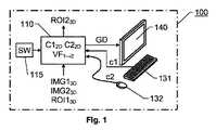
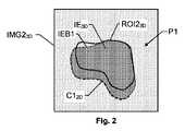
最初に、本発明の一実施形態に係る画像ハンドリングシステム100のブロック図を示す図1と、ターゲット画像における第1の平面内の第1の輪郭の第1の例を画像要素の辺縁及び第1の輪郭の例と共に示す図2を参照する。 First, FIG. 1 showing a block diagram of an
提案される画像ハンドリングシステム100は、データ処理ユニット110と、少なくとも1つのデータ入力ユニット131及び132と、ディスプレイユニット140を含む。 The proposed
データ処理ユニット110は、例えば、患者の器官又は身体構造体を表す変形し得る物理エンティティのリファレンス画像IMG13Dを受信するように構成される。リファレンス画像IMG13Dは、通常、X線コンピュータ断層撮影装置、磁気共鳴装置(例えば、磁気共鳴画像法MRI、核磁気共鳴画像法NMRI、又は磁気共鳴断層撮影法MRTを用いる)、超音波カメラ、又はコーンビームコンピュータ断層撮影法CBCTスキャナによって登録され得る比較的多数のボクセルを含んでいる3Dデータセットである。The
データ処理ユニット110はまた、物理エンティティのターゲット画像IMG23Dを受信するように構成され、ターゲット画像IMG23Dは、同様に、しかし必ずしもリファレンス画像IMG13Dを生成するのに用いたのと同じ装置又は同じタイプの装置ではないが、通常は、例えば、X線コンピュータ断層撮影装置、磁気共鳴装置(例えば、磁気共鳴画像法MRI、核磁気共鳴画像法NMRI、又は磁気共鳴断層撮影法MRTを用いる)、又は超音波カメラによって登録された比較的多数のボクセルを含んでいる3Dデータセットである。
加えて、データ処理ユニット110は、リファレンス画像IMG13Dにおける第1のボリュームを定義する第1の関心領域(region of interest)ROI13Dを受信するように構成される。第1の関心領域ROI13Dは、例えば、患者の個々の器官、器官系、組織、又はいくつかの他の身体構造体の限界境界に対応するリファレンス画像IMG13D上の特定の領域を定義するリファレンス画像要素を表す。リファレンス画像IMG13D及びターゲット画像IMG23Dと同様に、第1の関心領域ROI13Dは、ボクセルによって表され得る3Dデータセットである。しかしながら、第1の関心領域ROI13Dは、普通は、人間オペレータ、例えば、放射線科医によって手動で定義されているデータセットである。特定の由来に関係なく、第1の関心領域ROI13D、リファレンス画像IMG13D、及びターゲット画像IMG23Dは、1つ又は複数のデータインターフェースを介してデータ処理ユニット110に送られる。In addition, the
ディスプレイユニット140は、リファレンス画像IMG13D、ターゲット画像IMG23D、及び第1の関心領域ROI13Dを反映するグラフィックデータGDを提示するように構成される。したがって、ユーザ、例えば放射線科医は、コンピュータへのユーザコマンドを生成するための任意の公知の入力部材、例えば、キーボード131及び/又はコンピュータマウス132によって表され得る少なくとも1つのデータ入力ユニット131及び132を介してコマンドを入力することによって、好ましくは選択されたビューから見られる場合に対話形式で、画像データを視覚的に検査することができる。The
少なくとも1つのデータ入力ユニット131及び132は、それぞれユーザコマンドc1及びc2を受信するように構成される。ユーザコマンドc1及び/又はc2に応答して、データ処理ユニット110は、好ましくはディスプレイユニット140上に提示されたターゲット画像IMG23Dのビューに対応するターゲット画像IMG23Dを通る第1の平面内の第1の輪郭(contour)C12Dを定義するように構成される。ここで、ユーザコマンドc1及び/又はc2は、第1の輪郭C12Dがターゲット画像IMG23Dにおけるターゲット画像要素(image element)IE3Dの第1の辺縁(border)IEB1(例えば、特定の器官のアウトライン)の少なくとも一部と位置合わせされるように生成されると仮定する。いずれにしても、ターゲット画像要素IE3Dは、リファレンス画像IMG13Dにおけるリファレンス画像要素に対応する。At least one
データ処理ユニット110は、ターゲット画像IMG23Dにおける第2のボリュームを定義する第2の関心領域ROI23Dを決定するようにさらに構成される。本発明によれば、第2の関心領域ROI23Dは、第1の輪郭C12D、ターゲット画像IMG23D、及び第1の関心領域ROI13Dに基づいて決定される。The
図3a及び図3bは、リファレンス画像ROI13Dにおける第1の関心領域ROI13Dからターゲット画像IMG23Dにおける第2の関心領域ROI23Dがどのようにして得られるかを例示する。3a and 3b illustrate how a second region of interestROI23D from the first region of interestROI13D in the reference imageROI13D in the target imageIMG23D is how the obtained.
本発明の一実施形態によれば、データ処理ユニット110は、第1の関心領域ROI13Dと第2の関心領域ROI23Dとの関係性を記述するベクトルフィールドVF1→2を計算するようにさらに構成される。ベクトルフィールドVF1→2は、ベクトルフィールドVF1→2を介して第1の関心領域ROI13Dを変換することによって第2の関心領域ROI23Dを得ることができるような特性を有する。言い換えれば、第2の関心領域ROI23Dは、例えば、第1の関心領域ROI13DにベクトルフィールドVF1→2をかけることによって生成することができる。According to one embodiment of the present invention, the
さらに好ましくは、データ処理ユニット110は、第1の関心領域ROI13D及びベクトルフィールドVF1→2に基づいて第2の関心領域ROI23Dを生成するように構成される。次いで、データ処理ユニット110は、好ましくは、グラフィックデータGPがターゲット画像IMG23D上にオーバーレイされた第2の関心領域ROI23Dを反映するように、ディスプレイユニット140上に提示するためのグラフィックデータGPを生成するように構成される。その結果、ユーザは、ベクトルフィールドVF1→2(したがって第2の関心領域ROI23Dも)がターゲット画像IMG23Dにおける器官、器官系、組織、身体構造体などの十分に正確な定義であるか否かを再確認することができる。ベクトルフィールドVF1→2が容認できないほど不正確であることが判明するならば、ユーザがデータ品質を改善する手段を有することが望ましい。More preferably, the
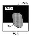
この目的のために、本発明の一実施形態によれば、データ処理ユニット110は、少なくとも1つのデータ入力ユニット131及び/又は132のそれぞれを介してさらなるユーザコマンドc1及び/又はc2を受信するようにさらに構成される。これに応答して、データ処理ユニット110は、図4に例示されるようにターゲット画像IMG23Dを通る第2の平面P2内の第2の輪郭C22Dを定義するように構成される。また、ユーザコマンドc1/c2は、第2の輪郭C22Dがターゲット画像IMG23Dにおけるターゲット画像要素IE3Dの第2の辺縁IEB2の少なくとも一部と位置合わせされるように生成されると仮定する。その後、データ処理ユニット110は、第2の輪郭C22Dにさらに基づいて第2の関心領域ROI23Dを決定するように構成される。図5は、元の第2の関心領域ROI23Dを更新された第2の関心領域ROI2’3Dへ調整する例を示す。For this purpose, according to one embodiment of the invention, the
第2の関心領域ROI23Dを前述のように補正/調整するときに、データ処理ユニット110は、図6、図7a、及び図7bを参照して後述する戦略のうちの1つ又は複数を適用することができる。When correcting / adjusting the second region of interestROI23D as described above, the
図6は、本発明の一実施形態に従って8つのボクセル中心V1、V2、V3、V4、V5、V6、V7、及びV8の凸結合に基づいて第2の関心領域ROI23Dと第1の平面P1又は第2の平面P2との交点V0がどのようにして計算されるかを例示する。図6では、交点V0の周りの内側ボックスは、ここでは、その内部でのデータ値が1及び同一であり、且つグラフィックデータGPがディスプレイユニット140上の特定の強度及び/又は色相によって表され得るボリュームを表す。FIG. 6 shows a second region of interestROI23D and a first plane P1 based on the convex combination of eight voxel centers V1, V2, V3, V4, V5, V6, V7, and V8 according to an embodiment of the present invention. Or it illustrates how the intersection V0 with the second plane P2 is calculated. In FIG. 6, the inner box around the intersection point V 0 here has a data value 1 and the same inside it, and the graphic data GP can be represented by a specific intensity and / or hue on the
コンピュータグラフィックス並びに医療データのコンピュータ支援画像処理では一般的な慣習であるように、第2の関心領域ROI23Dは三角形メッシュによって表されると仮定する。好ましくは、これは第1の関心領域ROI13Dにも当てはまる。もちろん、上記の第1の平面又は第2の平面がどのように配向されるかに関係なく、第2の関心領域ROI23Dと第1の平面又は第2の平面との交点の多くは、三角形メッシュ表現での三角形の角のうちの1つとは異なる点に生じるであろう。言い換えれば、交わりラインは、第2の関心領域ROI23Dを記述するベクトルフィールドの多数のボクセル中心を通らないであろう。したがって、特定の交点が計算されなければならない。As is common practice in computer graphics as well as computer-aided image processing of medical data, assume that the second region of interestROI23D is represented by a triangular mesh. Preferably this also applies to the first region of interestROI13D . Of course, regardless of how the first plane or the second plane is oriented, many of the intersections of the second region of interestROI23D and the first plane or the second plane are triangular. It will occur at a point different from one of the triangle corners in the mesh representation. In other words, the intersection line will not pass through the voxel centers of the vector field describing the second region of interestROI23D . Therefore, a specific intersection must be calculated.
本発明の一実施形態によれば、この計算は、輪郭(すなわちC12D又はC22D)からの偏差にペナルティを課す項を含んでいる非線形最適化問題として公式化される。ここで、二次元距離変換が以下のように用いられる。According to one embodiment of the present invention, this calculation is formulated as a nonlinear optimization problem that includes a term that penalizes deviation from the contour (ie,C12D orC22D ). Here, two-dimensional distance transformation is used as follows.
三角形メッシュによって表される第2の関心領域ROI23Dに関する平面P1又はP2内の輪郭C12D又はC22Dが定義されており、第2の関心領域ROI23Dは三角形メッシュによって表され、平面P1又はP2は第2の関心領域ROI23Dと交わるものとする。第2の関心領域ROI23Dの縁の組を定義し、この場合、交点はEとして生じる。A contourC12D orC22D in the plane P1 or P2 with respect to the second region of interestROI23D represented by the triangular mesh is defined, and the second region of interestROI23D is represented by the triangular mesh and is represented by the plane P1 or P2Shall intersect the second region of interestROI23D . Define a set of edges of the second region of interestROI23D , where the intersection occurs as E.
Eにおける各縁に関して、平面P1又はP2との交点を計算する。前述のように、結果的に得られる交点の組は、ベクトルフィールドのボクセル中心に通常は存在しない。交点をベクトルフィールドの観点で表すために、各交点V0は、平均値座標を用いて交点V0の近傍に存在する8つのボクセル中心V1、V2、V3、V4、V5、V6、V7、及びV8の凸結合によって計算される。このような点を仮想点viと呼び、ここで、
距離変換D(x)が、輪郭上でD(x)=0であり、他では>0であるように、平面P1又はP2内の輪郭C12D又はC22Dに関して計算される。これにより、D(x)は、ユークリッド距離を輪郭C12D又はC22Dへ近づける。A distance transform D (x) is calculated for the contourC12D orC22D in the plane P1 or P2 such that D (x) = 0 on the contour and> 0 otherwise. Thus, D (x) is closer to the Euclidean distance to the contourC12D orC22D.
輪郭C12D又はC22Dからの偏差にペナルティを課す非線形項は、次のように書くことができる。
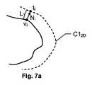
図7a及び図7bは、第1の平面P1又は第2の平面P2と第2の関心領域ROI23Dとの交点がそれに従って計算され得る、代替的な、すなわち、輪郭C12D又はC22Dに対する外部反復並びに内部反復を実行する反復プロセスによる戦略を例示する。7a and 7b show an alternative, i.e. external to the contourC12D orC22D , where the intersection of the first plane P1 or the second plane P2 and the second region of interestROI23D can be calculated accordingly Illustrates an iterative process strategy that performs iterations as well as internal iterations.
この場合も、第2の関心領域ROI23Dは三角形メッシュによって表される。ここで、輪郭C12D又はC22Dに起因する目的関数の非線形項は、主反復中は不変であり、主反復間で更新される。前述の戦略からの用語を用いると、違いは、輪郭C12D又はC22Dと平面P1又はP2との各交点viに関して、法線Niが縁の角での頂点法線の補間によって計算されることである。Again , the second region of interestROI23D is represented by a triangular mesh. Here, the nonlinear term of the objective function resulting from the contourC12D orC22D is invariant during the main iteration and is updated between the main iterations. Using the terminology of the above strategy, the differences, for each intersectionvi of the contourC12D orC22D the plane P1 or P2, the normalNi is calculated by interpolation of the vertex normals at the corner edge Is Rukoto.
次いで、法線Niが、平面P1又はP2上に投影され、長さLのインターバルの投影された法線に沿ってサーチが行われる。輪郭C12D又はC22Dとの交点tiが見つかる場合、これは非線形関数に加えられる:
ここで、重みwiは、1である場合があり、又は重みwiは、ほぼ直角な交わりが比較的高い重みをもたらし、ほぼ平行な交わりが比較的低い重みをもたらすような様態で、輪郭C12D又はC22Dと交わる角度に依存する場合がある。Here, the weightwi may be 1, or the weightwi is contoured in such a way that a substantially perpendicular intersection will result in a relatively high weight and a substantially parallel intersection will result in a relatively low weight.It may depend on the angle that intersectsC12D orC22D .
図7a及び図7bは、反復iの長さLのインターバル内で交点tiが見つかる状況の例を示し、したがって、対応する交点vi+1が、手順のその後の反復における輪郭C12Dに含まれる。7a and 7b show an example of a situation where an intersection pointti is found within an interval i of length i of iteration i, so that the corresponding intersection pointvi + 1 is included in the contourC12D in a subsequent iteration of the procedure.
反復に関するストップ基準が定義され、ストップ基準は、好ましくは発見的方法から選択される。例えば、ストップ基準は、新しい交点tiの数が減少する(すなわち、その後の反復i+1においてより低くなる)場合に、及び/又は交点tiの数が1つの反復から別の反復にかけてほぼ同じままであり始める場合に、満たされると考えられ得る。A stop criterion for the iteration is defined, and the stop criterion is preferably selected from a heuristic method. For example, the stop criterion may remain approximately the same when the number of new intersectionsti decreases (ie, becomes lower in subsequent iterations i + 1) and / or the number of intersection pointsti from one iteration to another. Can be considered to be satisfied if it begins to be.
データ処理ユニット110は、好ましくは、コンピュータプログラム製品SWが少なくとも1つのプロセッサ上で実行されるときにデータ処理ユニット110における少なくとも1つのプロセッサに前述のアクションを実行させるためのソフトウェアを含むコンピュータプログラム製品SWを記憶しているメモリユニット115を含む又はこれと通信接続する。 The
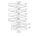
要約するために、図8の流れ図を参照して、画像データ及びユーザコマンドを処理するときに本発明に係るデータ処理ユニット110において実行される一般的方法をここで説明する。 To summarize, the general method performed in the
第1のステップ810は、変形し得る物理エンティティのリファレンス画像IMG13Dが受信されているかをチェックし、受信されている場合、ステップ820が後続する。受信されていない場合、手順はループバックし、ステップ810にとどまる。リファレンス画像IMG13Dは、例えば、コンピュータ断層撮影装置又は類似の装置によって登録された比較的多数のボクセルによって表される3Dデータセットである。A
ステップ820は、変形し得る物理エンティティのターゲット画像IMG23D、すなわち、リファレンス画像IMG13Dによって表される同じ物体/被検者の別の画像が受信されているかをチェックする。ステップ820においてターゲット画像IMG23Dが受信される場合、ステップ830が後続する。受信されない場合、手順はループバックし、ステップ820にとどまる。ターゲット画像IMG23Dは、例えば、コンピュータ断層撮影装置又は類似の装置によって登録された比較的多数のボクセルによって表される3Dデータセットである。Step 820checks whether a target imageIMG23D of the physical entity that can be deformed, ie another image of the same object / subject represented by the reference imageIMG13D , has been received. If the target imageIMG23D is received at
ステップ830は、1つ又は複数のデータ入力ユニット(例えば、コンピュータマウス及び/又はキーボード)を介してユーザコマンドが受信されているかをチェックし、該ユーザコマンドは、ターゲット画像IMG23Dを通る第1の平面内の第1の輪郭C12Dを定義することを目的として入力されると仮定される。このようなユーザコマンドが受信される場合、ステップ840が後続する。受信されない場合、手順はループバックし、ステップ830にとどまる。Step 830 checks whether a user command is received via one or more data input units (eg, a computer mouse and / or keyboard), and the user command passes through the target imageIMG23D. It is assumed that the input is intended to define a first contourC12D in the plane. If such a user command is received,
ステップは、第1の関心領域ROI13Dが受信されているかをチェックし、受信されている場合、ステップ850が後続する。受信されていない場合、手順はループバックし、ステップ840にとどまる。第1の関心領域ROI13Dは、リファレンス画像IMG13Dにおける第1のボリュームを定義し、第1のボリュームは、リファレンス画像要素、例えば患者の特定の器官/構造体を表す。第1の関心領域ROI13Dは、好ましくは、オペレータによって手動で定義され得るボクセルによって表される3Dデータセットである。The step checks whether the first region of interestROI13D has been received and if so,
ステップ810〜840の正確な順序は重要ではなく、ユーザコマンドがターゲット画像IMG23Dの後に受信されるという条件で本発明に従って変化し得ることに留意されたい。すなわち、ユーザコマンドは、ターゲット画像IMG23Dに基づいて入力される。Note that the exact order of steps 810-840 is not important and may vary according to the present invention provided that user commands are received after the target imageIMG23D . That is, the user command is input based on the target imageIMG23D .
ステップ850において、ユーザコマンドに応答して、ターゲット画像IMG23Dを通る第1の平面内の第1の輪郭C12Dが定義される。第1の輪郭C12Dは、ターゲット画像IMG23Dにおけるターゲット画像要素IE3Dの辺縁IEB1又はIEB2の少なくとも一部と位置合わせされると仮定される。ターゲット画像要素IE3Dは、リファレンス画像IMG13Dにおけるリファレンス画像要素に対応する。In
その後、ステップ860において、ターゲット画像IMG23Dにおける第2のボリュームを定義する第2の関心領域ROI23Dが決定される。第2の関心領域ROI23Dは、第1の輪郭C12D、ターゲット画像IMG23D、及び第1の関心領域ROI13Dに基づいて決定される。好ましくは、第2の関心領域ROI23Dを決定することに関連して、グラフィックデータGDがディスプレイユニット上に提示され、グラフィックデータGDは、ターゲット画像IMG23D及び第2の関心領域ROI23Dを反映する。Thereafter, in
その後、手順が終了する。しかしながら、本発明の好ましい実施形態によれば、例えば、ターゲット画像IMG23Dを通る第2の平面P2内の第2の輪郭C22Dを定義することによって、ターゲット画像IMG23Dにおける第2の関心領域ROI23Dと変形し得る物理エンティティとの間の何らかの不一致を調整するためのさらなるコマンドをユーザが入力することができる入力インターフェースがユーザに提供される。Thereafter, the procedure ends. However, according to a preferred embodiment of the present invention, for example, by defining a second contourC22D in the second plane P2 passing through the target imageIMG23D, second region of interest in the target imageIMG23DROI2An input interface is provided to the user that allows the user to enter further commands to adjust for any discrepancy between the3D and the deformable physical entity.
図8を参照して前述したプロセスステップ並びに任意のその後のステップのすべては、プログラムされたコンピュータ装置によって制御されてよい。さらに、図面を参照して前述した本発明の実施形態は、コンピュータ装置及びコンピュータ装置で行われるプロセスを含むが、本発明はまた、本発明を実現するように適合されたコンピュータプログラム、特に、キャリア上の又はキャリア内のコンピュータプログラムに拡張される。プログラムは、ソースコード、オブジェクトコード、部分的にコンパイルされた形態などのソースコードとオブジェクトコードの中間のコードの形態、又は本発明に係るプロセスの実施に用いるのに適した任意の他の形態であり得る。プログラムは、オペレーティングシステムの一部であってよく、又は別個のアプリケーションであってよい。キャリアは、プログラムを搬送することができる任意のエンティティ又はデバイスであり得る。例えば、キャリアは、フラッシュメモリ、ROM(読出し専用メモリ)、例えば、DVD(デジタルビデオ/バーサタイルディスク)、CD(コンパクトディスク)、又は半導体ROM、EPROM(消去可能プログラム可能読出し専用メモリ)、EEPROM(電気的消去可能プログラム可能読出し専用メモリ)、又は磁気記録媒体、例えば、フロッピーディスク又はハードディスクなどの記憶媒体を含む場合がある。さらに、キャリアは、無線によって又は他の手段によって電気ケーブル又は光学ケーブルを介して伝達され得る電気又は光信号などの伝送可能キャリアであり得る。プログラムが、ケーブル又は他のデバイス又は手段によって直接伝達され得る信号で具体化されるときに、キャリアは、このようなケーブル又はデバイス又は手段によって構成され得る。代替的に、キャリアは、プログラムが組み込まれる集積回路であってよく、集積回路は、該当するプロセスを実行する又は実行に用いるように適合される。 All of the process steps described above with reference to FIG. 8 as well as any subsequent steps may be controlled by a programmed computer device. Furthermore, although the embodiments of the present invention described above with reference to the drawings include a computer apparatus and processes performed on the computer apparatus, the present invention also includes a computer program, particularly a carrier, adapted to implement the present invention. Extends to computer programs on or in the carrier. The program may be in the form of source code, object code, partially compiled form of code such as source code and object code, or any other form suitable for use in performing the process according to the invention. possible. The program may be part of the operating system or may be a separate application. A carrier can be any entity or device capable of carrying a program. For example, the carrier may be flash memory, ROM (read only memory), eg, DVD (digital video / versatile disc), CD (compact disc), or semiconductor ROM, EPROM (erasable programmable read only memory), EEPROM (electric Erasable programmable read-only memory), or magnetic recording media, eg, storage media such as floppy disks or hard disks. Further, the carrier can be a transmissible carrier such as an electrical or optical signal that can be transmitted wirelessly or by other means via electrical or optical cables. When the program is embodied in a signal that can be transmitted directly by a cable or other device or means, the carrier may be constituted by such a cable or device or means. Alternatively, the carrier may be an integrated circuit in which the program is embedded, and the integrated circuit is adapted to perform or be used to perform the appropriate process.
本明細書で用いられるときの「備える、含む(comprises/comprising)」という用語は、表記された特徴、整数、ステップ、又はコンポーネントの存在を明記するために採用される。しかしながら、この用語は、1つ又は複数のさらなる特徴、整数、ステップ、又はコンポーネント、又はそのグループの存在又は追加を排除しない。 As used herein, the term “comprises / comprising” is employed to specify the presence of a stated feature, integer, step, or component. However, this term does not exclude the presence or addition of one or more additional features, integers, steps, or components, or groups thereof.
本発明は、図面で説明された実施形態に限られるものではなく、請求項の範囲内で自由に変化し得る。
The invention is not limited to the embodiments described in the drawings, but can vary freely within the scope of the claims.
Claims (14)
Translated fromJapanese変形し得る物理エンティティのリファレンス画像(IMG13D)、前記物理エンティティのターゲット画像(IMG23D)、および前記リファレンス画像(IMG13D)の第1のボリュームを定義する第1の関心領域(ROI13D)を受信するように構成されたデータ処理ユニット(110)であって、前記第1のボリュームは、リファレンス画像要素を示し、前記リファレンス画像(IMG13D)、前記ターゲット画像(IMG23D)、および前記第1の関心領域(ROI13D)が、各々それぞれの三次元データセットを含む、データ処理ユニット(110)と、
ユーザコマンド(c1;c2)を受信するように構成された少なくとも1つのデータ入力ユニット(131、132)と、
前記リファレンス画像(IMG13D)、前記ターゲット画像(IMG23D)、および前記第1の関心領域(ROI13D)を反映するグラフィックデータ(GD)を提示するように構成されたディスプレイユニット(140)、
を備え、
さらに前記データ処理ユニット(110)が、
前記ユーザコマンド(c1;c2)に応答して、前記ターゲット画像(IMG23D)を介して第1の平面(P1)内の第1の輪郭(C12D)を定義するように構成され、前記第1の輪郭(C12D)は、前記ターゲット画像(IMG23D)のターゲット画像要素(IE3D)の第1の辺縁(IEB1)の少なくとも一部と位置合わせされ、前記ターゲット画像要素(IE3D)は、前記リファレンス画像(IMG13D)の前記リファレンス画像要素に対応し、前記ターゲット画像要素(IE3D)の前記第1の辺縁(IEB1)が特定の器官のアウトラインを示し、
前記ターゲット画像(IMG23D)の第2のボリュームを定義する第2の関心領域(ROI23D)を決定するように構成され、前記第2の関心領域(ROI23D)は、前記第1の輪郭(C12D)、前記ターゲット画像(IMG23D)、及び前記第1の関心領域(ROI13D)に基づいて決定され、かつ
前記第1の関心領域(ROI13D)と前記第2の関心領域(ROI23D)との関係性を記述するベクトルフィールド(VF1→2)を計算するように構成され、前記ベクトルフィールド(VF1→2)を介して前記第1の関心領域(ROI13D)を変換することによって前記第2の関心領域(ROI23D)を得ることができる、
画像ハンドリングシステム(100)。An image handling system (100) comprising:
A reference image (IMG13D ) of a physical entity that can be transformed, a target image (IMG23D ) of the physical entity, and a first region of interest (ROI13D ) that defines a first volume of the reference image (IMG13D ). A data processing unit (110) configured to receive, wherein the first volume indicates a reference image element, the reference image (IMG13D ), the target image (IMG23D ), and the first volume A data processing unit (110), wherein each region of interest (ROI13D ) includes a respective three-dimensional dataset;
At least one data input unit (131, 132) configured to receive a user command (c1; c2);
A display unit (140) configured to present graphic data (GD) reflecting the reference image (IMG13D ), the target image (IMG23D ), and the first region of interest (ROI13D );
With
Further, the data processing unit (110) is
Responsive to the user command (c1; c2), configured to define a first contour (C12D ) in a first plane (P1) via the target image (IMG23D ); 1 contour (C12D ) is aligned with at least part of the first edge (IEB1) of the target image element (IE3D ) of the target image (IMG23D ), and the target image element (IE3D ) Corresponds to the reference image element of the reference image (IMG13D ), the first edge (IEB1) of the target image element (IE3D ) shows an outline of a particular organ,
The second region of interest (ROI23D ) is configured to determine a second region of interest (ROI23D ) that defines a second volume of the target image (IMG23D ), the second region of interest (ROI23D ) C12D), the target image (IMG23D), and the first is determined based on the region of interest (ROI13D), and the first region of interest (ROI13D) and the second region of interest (ROI23D ) To calculate a vector field (VF1 → 2 ) describing the relationship with the first region of interest (ROI13D ) via the vector field (VF1 → 2 ) To obtain the second region of interest (ROI23D ),
Image handling system (100).
前記第1の関心領域(ROI13D)及び前記ベクトルフィールド(VF1→2)に基づいて前記第2の関心領域(ROI23D)を生成するように構成され、かつ
前記ディスプレイユニット(140)上に提示するためのグラフィックデータ(GP)を生成するように構成され、前記グラフィックデータ(GP)は、前記ターゲット画像(IMG23D)上にオーバーレイされた前記第2の関心領域(ROI23D)を反映する、
請求項1に記載の画像ハンドリングシステム(100)。The data processing unit (110) is further configured to generate the second region of interest (ROI23D ) based on thefirst region of interest (ROI13D ) and the vector field (VF1 → 2 ). The graphic data (GP) for presentation on the display unit (140), the graphic data (GP) being overlaid on the target image (IMG23D ) Reflecting the region of interest (ROI23D ),
The image handling system (100) of claim 1.
さらなるユーザコマンド(c1;c2)を受信し、これに応答して、前記ターゲット画像(IMG23D)を介して第2の平面(P2)内の第2の輪郭(C22D)を定義し、前記第2の輪郭(C22D)は、前記ターゲット画像(IMG23D)の前記ターゲット画像要素(IE3D)の第2の辺縁(IEB2)の少なくとも一部と位置合わせされ、前記ターゲット画像要素(IE3D)の前記第2の辺縁(IEB2)が、特定の器官のアウトラインを示し、かつ
前記第2の輪郭(C22D)に基づいて前記第2の関心領域(ROI23D)を決定する、
ようにさらに構成される、
請求項2に記載の画像ハンドリングシステム(100)。The data processing unit (110) is
Receiving a further user command (c1; c2) and in response defining a second contour (C22D ) in a second plane (P2) via the target image (IMG23D ), A second contour (C22D ) is aligned with at least a portion of a second edge (IEB2) of the target image element (IE3D ) of the target image (IMG23D ), and the target image element (IE3D ) the second edge (IEB2) indicates the outline of a particular organ and determines the second region of interest (ROI23D ) based on the second contour (C22D ),
Further configured as
The image handling system (100) of claim2 .
請求項1〜3のいずれか一項に記載の画像ハンドリングシステム(100)。The data processing unit (110) has a nonlinear optimization algorithm applied to the first contour (C12D ) and an intersection of the second region of interest (ROI23D ) and the first plane (P1). based on the second is configured to determine a region of interest (ROI23D), wherein said nonlinear optimization algorithm, the first contour and the second region of interest (ROI23D from(C1 2D) ) Configured to penalize deviations,
The image handling system (100) according to any one of claims 1 to 3.
前記非線形最適化アルゴリズムが、
前記第2の関心領域(ROI23D)と前記第1の平面(P1)との交点の組を計算し、前記交点の組における各交点(V0)は、平均値座標を用いて前記交点(V0)の近傍に存在する8つのボクセル中心(V1、V2、V3、V4、V5、V6、V7、V8)の凸結合によって計算され、かつ
各計算された交点と前記第1の輪郭(C12D)との間のユークリッド距離に二次元距離変換を適用する、
ように構成される、
請求項4に記載の画像ハンドリングシステム(100)。The second region of interest (ROI23D ) is represented by a triangular mesh;
The nonlinear optimization algorithm is
A set of intersections between the second region of interest (ROI23D ) and the first plane (P1) is calculated, and each intersection (V0) in the set of intersections is calculated using the average coordinate. ) Calculated by the convex combination of eight voxel centers (V1, V2, V3, V4, V5, V6, V7, V8) inthe vicinity of each calculated intersection point and the first contour (C12D ) Apply a two-dimensional distance transformation to the Euclidean distance between and
Configured as
The image handling system (100) of claim 4.
前記非線形最適化アルゴリズムが、
前記第2の関心領域(ROI23D)と前記第1の平面(P1)との交点の組を計算し、かつ前記交点の組における各交点に関して、
前記第2の関心領域(ROI23D)から前記第1の平面(P1)への法線投影を決定し、前記法線投影は所定の長さのインターバル内で延び、前記所定の長さ内で前記法線が前記第1の輪郭(C12D)と接触点で交わる場合、前記接触点は、更新された第2の関心領域の仮の限界点として含まれ、かつ
ストップ基準が満たされるまで、前記更新された第2の関心領域に基づいて前記決定するステップを繰り返す、
ように構成される、
請求項4に記載の画像ハンドリングシステム(100)。The second region of interest (ROI23D ) is represented by a triangular mesh;
The nonlinear optimization algorithm is
Calculating a set of intersections of the second region of interest (ROI23D ) and the first plane (P1), and for each intersection in the set of intersections,
Determining a normal projection from the second region of interest (ROI23D ) to the first plane (P1), the normal projection extending within a predetermined length interval, and within the predetermined length; If the normal intersects the first contour (C12D ) at the contact point, the contact point is included as a temporary limit point of the updated second region of interest and until a stop criterion is satisfied, Repeating the determining step based on the updated second region of interest;
Configured as
The image handling system (100) of claim 4.
変形し得る物理エンティティのリファレンス画像(IMG13D)を受信するステップと、
前記物理エンティティのターゲット画像(IMG23D)を受信するステップと、
前記リファレンス画像(IMG13D)における第1のボリュームを定義する第1の関心領域(ROI13D)を受信するステップであって、前記第1のボリュームは、リファレンス画像要素を示し、前記リファレンス画像(IMG13D)、前記ターゲット画像(IMG23D)、および前記第1の関心領域(ROI13D)が、各々それぞれの三次元データセットを含む、ステップと、
少なくとも1つのデータ入力ユニット(131、132)を介してユーザコマンド(c1;c2)を受信するステップと、
ディスプレイユニット(140)上にグラフィックデータ(GD)を提示するステップであって、前記グラフィックデータ(GD)は、前記リファレンス画像(IMG13D)、前記ターゲット画像(IMG23D)、及び前記第1の関心領域(ROI13D)を反映する、ステップ
を含み、
さらに前記方法が、
前記ユーザコマンド(c1;c2)に応答して、前記ターゲット画像(IMG23D)を通る第1の平面(P1)内の第1の輪郭(C12D)を定義するステップであって、前記第1の輪郭(C12D)は、前記ターゲット画像(IMG23D)におけるターゲット画像要素(IE3D)の第1の辺縁(IEB1)の少なくとも一部と位置合わせされ、前記ターゲット画像要素(IE3D)は、前記リファレンス画像(IMG13D)における前記リファレンス画像要素に対応し、前記ターゲット画像要素(IE3D)の前記第1の辺縁(IEB1)が、特定の器官のアウトラインを示す、ステップと、
前記ターゲット画像(IMG23D)における第2のボリュームを定義する第2の関心領域(ROI23D)を決定するステップであって、前記第2の関心領域(ROI23D)は、前記第1の輪郭(C12D)、前記ターゲット画像(IMG23D)、及び前記第1の関心領域(ROI13D)に基づいて決定される、ステップと、および
前記第1の関心領域(ROI13D)と前記第2の関心領域(ROI23D)との関係性を記述するベクトルフィールド(VF1→2)を計算するステップであって、前記ベクトルフィールド(VF1→2)を介して前記第1の関心領域(ROI13D)を変換することによって前記第2の関心領域(ROI23D)を得ることができるステップ
をさらに含む、
方法。A method of handling images,
Receiving a reference image (IMG13D ) of a deformable physical entity;
Receiving a target image (IMG23D ) of the physical entity;
Receiving a first region of interest (ROI13D ) defining a first volume in the reference image (IMG13D ), wherein the first volume indicates a reference image element and the reference image (IMG13D ), the target image (IMG23D ), and the first region of interest (ROI13D ) each comprise a respective three-dimensional data set;
Receiving a user command (c1; c2) via at least one data input unit (131, 132);
Presenting graphic data (GD) on a display unit (140), the graphic data (GD) comprising the reference image (IMG13D ), the target image (IMG23D ), and the first interest; Reflecting the region (ROI13D ),
The method further comprises:
In response to the user command (c1; c2), defining a first contour (C12D ) in a first plane (P1) passing through the target image (IMG23D ), the first contour(C1 2D), said at least a portion with the alignment of the target image element in the target image (IMG23D) first edge of(IE 3D) (IEB1), the target image element(IE 3D) is Corresponding to the reference image element in the reference image (IMG13D ), wherein the first edge (IEB1) of the target image element (IE3D ) indicates an outline of a particular organ;
Determining a second region of interest (ROI23D ) that defines a second volume in the target image (IMG23D ), wherein the second region of interest (ROI23D ) is the first contour ( C12D ), the target image (IMG23D ), and the first region of interest (ROI13D ), and the first region of interest (ROI13D ) and the second region of interest Calculating a vector field (VF1 → 2 ) describing the relationship with the region (ROI23D ), the first region of interest (ROI13D ) via the vector field (VF1 → 2 ) Further comprising obtaining the second region of interest (ROI23D ) by transforming
Method.
前記ディスプレイユニット(140)上に提示するためのグラフィックデータ(GP)を生成するステップであって、前記グラフィックデータ(GP)は、前記ターゲット画像(IMG23D)上にオーバーレイされた前記第2の関心領域(ROI23D)を反映する、ステップ
をさらに含む、
請求項7に記載の方法。Generating the second region of interest (ROI23D ) based on thefirst region of interest (ROI13D ) and the vector field (VF1 → 2 );
Generating graphic data (GP) for presentation on the display unit (140), wherein the graphic data (GP) is overlaid on the target image (IMG23D ) Reflecting the region (ROI23D ), further comprising:
The method of claim 7.
前記第2の輪郭(C22D)にさらに基づいて前記第2の関心領域(ROI23D)を決定するステップであって、前記ターゲット画像要素(IE3D)の前記第2の辺縁(IEB2)が、特定の器官のアウトラインを示す、ステップ、
をさらに含む、
請求項7または請求項8に記載の方法。Receiving a further user command (c1; c2), in response, defining a second contour (C22D ) in a second plane (P2) through the target image (IMG23D ) The second contour (C22D ) is aligned with at least a portion of a second edge (IEB2) of the target image element (IE3D ) in the target image (IMG23D ), And determining the second region of interest (ROI23D ) further based on the second contour (C22D ), the second edge of the target image element (IE3D ) (IEB2) shows the outline of a particular organ, step,
Further including
9. A method according to claim 7 or claim 8.
をさらに含む、
請求項7〜請求項9のいずれか一項に記載の方法。Based on the non-linear optimization algorithm applied to the first contour (C12D ) and the intersection of the second region of interest (ROI23D ) and the first plane (P1), the second region of interest ( ROI23D ), wherein the nonlinear optimization algorithm is configured to penalize a deviation of the second region of interest (ROI23D ) from the first contour (C12D ) , Steps,
Further including
The method according to any one of claims 7 to 9.
前記方法が、
前記第2の関心領域(ROI23D)と前記第1の平面(P1)との交点の組を計算するステップであって、前記交点の組における各交点(V0)は、平均値座標を用いて前記交点(V0)の近傍に存在する8つのボクセル中心(V1、V2、V3、V4、V5、V6、V7、V8)の凸結合によって計算されるステップと、および
各計算された交点と前記第1の輪郭(C12D)との間のユークリッド距離に二次元距離変換を適用するステップ、
を含む、
請求項10に記載の方法。The second region of interest (ROI23D ) is represented by a triangular mesh, and the method comprises:
Calculating a set of intersections between the second region of interest (ROI23D ) and the first plane (P1), wherein each intersection (V0) in the set of intersections is calculated using an average value coordinate A step calculated by a convex combination of eight voxel centers (V1, V2, V3, V4, V5, V6, V7, V8) existing inthe vicinity of the intersection (V0), and each calculated intersection and the first Applying a two-dimensional distance transformation to the Euclidean distance to one contour (C12D );
including,
The method of claim 10.
前記方法が、
前記第2の関心領域(ROI23D)と前記第1の平面(P1)との交点の組を計算するステップと、
前記交点の組における各交点に関して、
前記第2の関心領域(ROI23D)から前記第1の平面(P1)への法線投影を決定するステップであって、前記法線投影は所定の長さのインターバル内で延び、前記所定の長さ内で前記法線が前記第1の輪郭(C12D)と接触点で交わる場合、前記接触点は、更新された第2の関心領域の仮の限界点として含まれる、ステップと、
ストップ基準が満たされるまで、前記更新された第2の関心領域に基づいて前記決定するステップを繰り返すステップ、
を含む、
請求項10に記載の方法。The second region of interest (ROI23D ) is represented by a triangular mesh;
The method comprises
Calculating a set of intersection points of the second region of interest (ROI23D ) and the first plane (P1);
For each intersection in the intersection set,
Determining a normal projection from the second region of interest (ROI23D ) onto the first plane (P1), the normal projection extending within a predetermined length interval, If the normal intersects the first contour (C12D ) at a contact point within a length, the contact point is included as a temporary limit point of the updated second region of interest;
Repeating the determining step based on the updated second region of interest until a stop criterion is satisfied;
including,
The method of claim 10.
Applications Claiming Priority (3)
| Application Number | Priority Date | Filing Date | Title |
|---|---|---|---|
| EPEP15173679.0 | 2015-06-24 | ||
| EP15173679.0AEP3109824B1 (en) | 2015-06-24 | 2015-06-24 | System and method for handling image data |
| PCT/EP2016/064516WO2016207271A1 (en) | 2015-06-24 | 2016-06-23 | System and method for handling image data |
Publications (3)
| Publication Number | Publication Date |
|---|---|
| JP2018538010A JP2018538010A (en) | 2018-12-27 |
| JP2018538010A5 JP2018538010A5 (en) | 2019-11-14 |
| JP6620172B2true JP6620172B2 (en) | 2019-12-11 |
Family
ID=53488246
Family Applications (1)
| Application Number | Title | Priority Date | Filing Date |
|---|---|---|---|
| JP2017566113AActiveJP6620172B2 (en) | 2015-06-24 | 2016-06-23 | System and method for handling image data |
Country Status (5)
| Country | Link |
|---|---|
| US (1) | US10467761B2 (en) |
| EP (1) | EP3109824B1 (en) |
| JP (1) | JP6620172B2 (en) |
| CN (1) | CN107924565B (en) |
| WO (1) | WO2016207271A1 (en) |
Families Citing this family (2)
| Publication number | Priority date | Publication date | Assignee | Title |
|---|---|---|---|---|
| EP3441936B1 (en)* | 2017-08-11 | 2021-04-21 | Siemens Healthcare GmbH | Method for evaluating image data of a patient after a minimally invasive procedure, evaluation device, computer program and electronically readable data carrier |
| EP3756728A1 (en)* | 2019-06-24 | 2020-12-30 | Vision RT Limited | Patient motion tracking system configured for automatic roi generation |
Family Cites Families (28)
| Publication number | Priority date | Publication date | Assignee | Title |
|---|---|---|---|---|
| US7903857B2 (en)* | 2006-04-17 | 2011-03-08 | Siemens Medical Solutions Usa, Inc. | Robust click-point linking with geometric configuration context: interactive localized registration approach |
| EP2036037B1 (en)* | 2006-05-18 | 2013-04-17 | Resonant Medical Inc. | Methods and systems for segmentation using boundary reparameterization |
| EP2081494B1 (en)* | 2006-11-16 | 2018-07-11 | Vanderbilt University | System and method of compensating for organ deformation |
| JP2011504115A (en)* | 2007-10-18 | 2011-02-03 | ザ ユニバーシティ オブ ノース カロライナ アット チャペル ヒル | Method, system and computer-readable medium for mapping a region of a model of an object containing anatomical structures from a single image data to an image used for diagnostic or therapeutic intervention |
| US9767573B2 (en)* | 2010-01-22 | 2017-09-19 | Vanderbilt University | System and method for correcting data for deformations during image-guided surgical procedures |
| US8805035B2 (en)* | 2010-05-03 | 2014-08-12 | Mim Software, Inc. | Systems and methods for contouring a set of medical images |
| US9996929B2 (en)* | 2010-10-27 | 2018-06-12 | Varian Medical Systems International Ag | Visualization of deformations using color overlays |
| WO2012069965A1 (en) | 2010-11-23 | 2012-05-31 | Koninklijke Philips Electronics N.V. | Interactive deformation map corrections |
| WO2012080949A1 (en)* | 2010-12-15 | 2012-06-21 | Koninklijke Philips Electronics N.V. | Contour guided deformable image registration |
| US9430831B2 (en)* | 2011-03-15 | 2016-08-30 | Koninklijke Philips N.V. | Correlated image mapping pointer |
| US8520923B2 (en)* | 2011-08-06 | 2013-08-27 | Carestream Health, Inc. | Reporting organ volume for a medical digital image |
| CN102629391A (en)* | 2012-02-28 | 2012-08-08 | 华北水利水电学院 | Three-dimensional space structure graph cutting and slicing method based on digital graph medium |
| US8824733B2 (en)* | 2012-03-26 | 2014-09-02 | Tk Holdings Inc. | Range-cued object segmentation system and method |
| CN103356218B (en)* | 2012-03-31 | 2015-06-24 | 上海西门子医疗器械有限公司 | Method and system for X-ray computed tomography |
| ES2627108T3 (en)* | 2012-04-03 | 2017-07-26 | Intrasense | ROI remapping method preserving the topology between medical images |
| WO2013155300A1 (en)* | 2012-04-11 | 2013-10-17 | The Trustees Of Columbia University In The City Of New York | Techniques for segmentation of organs and tumors and objects |
| US10354377B2 (en)* | 2012-04-11 | 2019-07-16 | The Trustees Of Columbia University In The City Of New York | Techniques for segmentation of lymph nodes, lung lesions and other solid or part-solid objects |
| WO2014025783A1 (en)* | 2012-08-06 | 2014-02-13 | Vanderbilt University | Enhanced method for correcting data for deformations during image guided procedures |
| CN102968822A (en)* | 2012-08-23 | 2013-03-13 | 华南理工大学 | Three-dimensional medical image segmentation method based on graph theory |
| KR102123061B1 (en)* | 2012-11-27 | 2020-06-16 | 삼성전자주식회사 | Boundary segmentation apparatus and method based on user interaction |
| CN103236058B (en)* | 2013-04-25 | 2016-04-13 | 内蒙古科技大学 | Obtain the method for volume of interest of four-dimensional heart image |
| JP6182045B2 (en)* | 2013-10-11 | 2017-08-16 | キヤノン株式会社 | Image processing apparatus and method |
| JP6489800B2 (en)* | 2014-01-16 | 2019-03-27 | キヤノン株式会社 | Image processing apparatus, image diagnostic system, image processing method, and program |
| CN104490413A (en)* | 2014-12-05 | 2015-04-08 | 杭州市肿瘤医院 | In-vitro locator beacon and location registration method using locator beacon |
| CN104408734B (en)* | 2014-12-11 | 2017-10-27 | 山东师范大学 | Joint image splits the adaptive targets Zone switching method with deformable registration technology |
| CN104599268A (en)* | 2015-01-06 | 2015-05-06 | 广州医科大学附属肿瘤医院 | Local area accurate deformation registration algorithm combining point registration |
| CN104637056B (en)* | 2015-02-02 | 2018-02-23 | 复旦大学 | Medicine CT image adrenal tumor dividing method based on rarefaction representation |
| US11449208B2 (en)* | 2017-07-06 | 2022-09-20 | Varian Medical Systems International Ag | Interactive and intuitive method to shape 3D dose distribution during optimization of IMRT plans |
- 2015
- 2015-06-24EPEP15173679.0Apatent/EP3109824B1/enactiveActive
- 2016
- 2016-06-23USUS15/738,891patent/US10467761B2/enactiveActive
- 2016-06-23CNCN201680037212.4Apatent/CN107924565B/enactiveActive
- 2016-06-23WOPCT/EP2016/064516patent/WO2016207271A1/ennot_activeCeased
- 2016-06-23JPJP2017566113Apatent/JP6620172B2/enactiveActive
Also Published As
| Publication number | Publication date |
|---|---|
| CN107924565B (en) | 2021-09-14 |
| US20180182106A1 (en) | 2018-06-28 |
| JP2018538010A (en) | 2018-12-27 |
| US10467761B2 (en) | 2019-11-05 |
| EP3109824A1 (en) | 2016-12-28 |
| WO2016207271A1 (en) | 2016-12-29 |
| EP3109824B1 (en) | 2019-03-20 |
| CN107924565A (en) | 2018-04-17 |
Similar Documents
| Publication | Publication Date | Title |
|---|---|---|
| US9710880B2 (en) | User-guided shape morphing in bone segmentation for medical imaging | |
| CN102667857B (en) | Bone in X-ray photographs suppresses | |
| US9697600B2 (en) | Multi-modal segmentatin of image data | |
| CN107851337B (en) | Interactive grid editing | |
| US7773786B2 (en) | Method and apparatus for three-dimensional interactive tools for semi-automatic segmentation and editing of image objects | |
| EP2877980B1 (en) | Dose deformation error calculation method and system | |
| JP6005359B2 (en) | Device that determines the size change of an object | |
| US9547906B2 (en) | System and method for data driven editing of rib unfolding | |
| US20180064409A1 (en) | Simultaneously displaying medical images | |
| US11565129B2 (en) | Binary tracking of an anatomical tracking structure on medical images | |
| US9836891B2 (en) | Shape data generation method and apparatus | |
| US10922853B2 (en) | Reformatting while taking the anatomy of an object to be examined into consideration | |
| US12131525B2 (en) | Multi-task deep learning method for a neural network for automatic pathology detection | |
| JP6620172B2 (en) | System and method for handling image data | |
| CN101802877A (en) | Path approximation rendering | |
| CN102138159B (en) | Simultaneous model-based segmentation of objects satisfying pre-defined spatial relationships | |
| EP4128145B1 (en) | Combining angiographic information with fluoroscopic images | |
| JP2025514331A (en) | Method for quantifying patient setup errors in radiation therapy - Patents.com | |
| Samavati et al. | A hybrid biomechanical intensity based deformable image registration of lung 4DCT |
Legal Events
| Date | Code | Title | Description |
|---|---|---|---|
| A621 | Written request for application examination | Free format text:JAPANESE INTERMEDIATE CODE: A621 Effective date:20190304 | |
| A871 | Explanation of circumstances concerning accelerated examination | Free format text:JAPANESE INTERMEDIATE CODE: A871 Effective date:20190304 | |
| A521 | Request for written amendment filed | Free format text:JAPANESE INTERMEDIATE CODE: A523 Effective date:20190305 | |
| A975 | Report on accelerated examination | Free format text:JAPANESE INTERMEDIATE CODE: A971005 Effective date:20190405 | |
| A131 | Notification of reasons for refusal | Free format text:JAPANESE INTERMEDIATE CODE: A131 Effective date:20190416 | |
| A521 | Request for written amendment filed | Free format text:JAPANESE INTERMEDIATE CODE: A523 Effective date:20190712 | |
| A131 | Notification of reasons for refusal | Free format text:JAPANESE INTERMEDIATE CODE: A131 Effective date:20190910 | |
| A524 | Written submission of copy of amendment under article 19 pct | Free format text:JAPANESE INTERMEDIATE CODE: A524 Effective date:20191001 | |
| TRDD | Decision of grant or rejection written | ||
| A01 | Written decision to grant a patent or to grant a registration (utility model) | Free format text:JAPANESE INTERMEDIATE CODE: A01 Effective date:20191021 | |
| A61 | First payment of annual fees (during grant procedure) | Free format text:JAPANESE INTERMEDIATE CODE: A61 Effective date:20191118 | |
| R150 | Certificate of patent or registration of utility model | Ref document number:6620172 Country of ref document:JP Free format text:JAPANESE INTERMEDIATE CODE: R150 | |
| R250 | Receipt of annual fees | Free format text:JAPANESE INTERMEDIATE CODE: R250 | |
| R250 | Receipt of annual fees | Free format text:JAPANESE INTERMEDIATE CODE: R250 | |
| R250 | Receipt of annual fees | Free format text:JAPANESE INTERMEDIATE CODE: R250 |